EP2364046A2 - A method of updating channel information by a mobile station that is in power saving mode - Google Patents
A method of updating channel information by a mobile station that is in power saving mode Download PDFInfo
- Publication number
- EP2364046A2 EP2364046A2 EP11004513A EP11004513A EP2364046A2 EP 2364046 A2 EP2364046 A2 EP 2364046A2 EP 11004513 A EP11004513 A EP 11004513A EP 11004513 A EP11004513 A EP 11004513A EP 2364046 A2 EP2364046 A2 EP 2364046A2
- Authority
- EP
- European Patent Office
- Prior art keywords
- channel descriptor
- message
- paging
- dcd
- field
- Prior art date
- Legal status (The legal status is an assumption and is not a legal conclusion. Google has not performed a legal analysis and makes no representation as to the accuracy of the status listed.)
- Withdrawn
Links
Images


Classifications
-
- H—ELECTRICITY
- H04—ELECTRIC COMMUNICATION TECHNIQUE
- H04W—WIRELESS COMMUNICATION NETWORKS
- H04W52/00—Power management, e.g. TPC [Transmission Power Control], power saving or power classes
- H04W52/02—Power saving arrangements
- H04W52/0209—Power saving arrangements in terminal devices
- H04W52/0212—Power saving arrangements in terminal devices managed by the network, e.g. network or access point is master and terminal is slave
- H04W52/0216—Power saving arrangements in terminal devices managed by the network, e.g. network or access point is master and terminal is slave using a pre-established activity schedule, e.g. traffic indication frame
-
- H—ELECTRICITY
- H04—ELECTRIC COMMUNICATION TECHNIQUE
- H04W—WIRELESS COMMUNICATION NETWORKS
- H04W48/00—Access restriction; Network selection; Access point selection
- H04W48/16—Discovering, processing access restriction or access information
-
- H—ELECTRICITY
- H04—ELECTRIC COMMUNICATION TECHNIQUE
- H04W—WIRELESS COMMUNICATION NETWORKS
- H04W68/00—User notification, e.g. alerting and paging, for incoming communication, change of service or the like
- H04W68/005—Transmission of information for alerting of incoming communication
-
- Y—GENERAL TAGGING OF NEW TECHNOLOGICAL DEVELOPMENTS; GENERAL TAGGING OF CROSS-SECTIONAL TECHNOLOGIES SPANNING OVER SEVERAL SECTIONS OF THE IPC; TECHNICAL SUBJECTS COVERED BY FORMER USPC CROSS-REFERENCE ART COLLECTIONS [XRACs] AND DIGESTS
- Y02—TECHNOLOGIES OR APPLICATIONS FOR MITIGATION OR ADAPTATION AGAINST CLIMATE CHANGE
- Y02D—CLIMATE CHANGE MITIGATION TECHNOLOGIES IN INFORMATION AND COMMUNICATION TECHNOLOGIES [ICT], I.E. INFORMATION AND COMMUNICATION TECHNOLOGIES AIMING AT THE REDUCTION OF THEIR OWN ENERGY USE
- Y02D30/00—Reducing energy consumption in communication networks
- Y02D30/70—Reducing energy consumption in communication networks in wireless communication networks
Definitions
- the present invention relates to a method of updating channel information, and more particularly, to a method of updating channel information by a mobile station that is in power saving mode.
- a paging zone refers to all the paging areas covered by a plurality of base stations.
- all the base stations in the same paging zone share a same paging cycle (i.e., Paging_Cycle) and a same paging offset (i.e., Paging_Offset).
- a mobile station can request to enter a power saving mode from the base station (BS).
- the BS can then permit the MS to enter the power saving mode by transmitting its paging group identification (i.e, Paging_Group_ID) and the paging cycle and the paging offset, both corresponding to the paging group ID.
- Paging_Group_ID paging group identification
- the MS can then enter the power saving mode.
- the MS receives a broadcast message in a form of a paging broadcast message (i.e., MOB-PAG-ADV) from the BS at specified paging cycle. From the paging broadcast message, the MS can determine whether to maintain or terminate the power saving mode.
- a broadcast message in a form of a paging broadcast message (i.e., MOB-PAG-ADV) from the BS at specified paging cycle. From the paging broadcast message, the MS can determine whether to maintain or terminate the power saving mode.
- the MS can terminate the power saving mode anytime. Conversely, if a situation arises where the MS, which is in the power saving mode, has to receive downlink traffic from the BS, the BS sends the paging broadcast message to instruct the MS to terminate the power saving mode.
- the MS which is in a power saving mode fails to receive the paging broadcast message at the specified time as a result of moving to another paging zone or by failure to synchronize, then the MS has to terminate the power saving mode.
- the present invention is directed to a method of updating channel information by a mobile station that is in power saving mode that substantially obviates one or more problems due to limitations and disadvantages of the related art.
- An object of the present invention is to provide a method of updating channel information by a mobile station that is in power saving mode.
- Another object of the present invention is to provide a method of providing channel information by a base station to a mobile station that is in power saving mode.
- a further object of the present invention is to provide an apparatus for updating channel information by a mobile station that is in power saving mode.
- a method of updating channel information by a mobile station (MS) that is in power saving mode includes the MS which receives status information of a first channel descriptor and a transmission frame information which includes when the first channel descriptor is to be transmitted. Furthermore, the MS compares status information of the first channel descriptor with status information of a second channel descriptor. Here, the second channel descriptor is stored in the MS. Lastly, if the compared status information are different, the MS receives the first channel descriptor according to the transmission frame information.
- a method of providing channel information by a base station (BS) to a mobile station (MS) that is in power saving mode includes the BS which transmits status information of a first channel descriptor and transmission frame information which includes when the first channel descriptor is to be transmitted. Moreover, the BS transmits the first channel descriptor according to the transmission frame information.
- an apparatus for updating channel information where the apparatus is in power saving mode.
- the apparatus includes a receiver for receiving status information of a first channel descriptor and a transmission frame information which includes when the first channel descriptor is to be transmitted.
- the apparatus includes a comparator for comparing status information of the first channel descriptor with status information of a second channel descriptor.
- the second channel descriptor is stored in a memory of the MS.
- the receiver is used to receive the first channel descriptor according to the transmission frame information, if the compared status information from the comparator are different
- Another aspect of the present invention includes a method of updating channel information by a mobile station (MS) that is in power saving mode.
- the MS receives status information of a channel descriptor and a transmission frame information which includes when the channel descriptor is to be transmitted. Furthermore, the MS recognizes a change in the status information of the channel descriptor since a last decoded status information. Lastly, the MS receives the channel descriptor according to the transmission frame information.
- a method of updating channel information by a mobile station (MS) that is in power saving mode includes the MS which receives a transmission frame information which includes a specified frame at which a channel descriptor is to be transmitted. Moreover, the MS recognizes the specified frame for receiving the channel descriptor which contains information different from channel descriptor information stored in the MS. Lastly, the MS receives the channel descriptor at the specified frame.
- MS mobile station
- the MS in a power saving mode receives a paging broadcast message (i.e., MOB_PAG_ADV), which is transmitted according to a paging cycle, from the BS in the paging zone.
- a paging broadcast message i.e., MOB_PAG_ADV
- the power saving mode can be an idle mode or a sleep mode.
- Table 1 represents an example of a Paging-Group-Action message for forming a paging zone.
- the base stations can transmit messages between each other via a wired connection (e.g., a cable).
- the target BS is the BS that receives the message from another BS.
- the sender BS is the BS that transmits the message from another BS.
- a paging-group-action message can include information on a plurality of paging groups.
- the base stations can gain access to the paging cycle and the paging offset of each paging zone from the paging-group-action, which is shared by base stations.
- Table 2 is an example of a deregistration request message (i.e., DREG_REQ), which is a message by the MS to request to enter a power saving mode.
- the MS can set a De-Registration Request Code of the DREG_REQ message to '0x01,' and request for deregistration from a serving BS. That is, the MS requests the BS for permission to enter a power saving mode.
- the serving BS refers to the BS which sends paging information to mobile stations in its coverage area.
- the MS can send its preferred paging cycle in the DREG_REQ message.
- Table 3 is an example of a deregistration command message (i.e., DREG_CMD).
- DREG_CMD deregistration command message
- the MS wait or cease the requests to enter the power saving mode
- Table 4 is an example of action codes of a deregistration command (i.e., DREG_CMD) message.
- Action Code Action 0x00 SS shall leave the current channel and attempt to access another channel 0x01 SS shall listen to the current channel but shall not transmit until an RES-CMD message or DREG_CMD with Action Code 0x00 is received
- 0x02 SS shall listen to the current channel but only transmit on the Basic, Primary Management and Secondary Management Connections.
- 0x03 SS shall return to normal operation and may transmit on any of its active connections.
- 0x04 SS shall terminate current Normal Operation with the BS; the BS shall transmit this action code only in response to any SS DREG-REQ 0x05 required MSS de-registration from Serving BS and request initiation of MSS Idle Mode 0x06
- the MSS may retransmit the DREG-REQ message after the time duration (REQ-duration) given by 0x07
- the MSS shall not retransmit the DREG-REQ message and shall wait the DREG_CMD message 0x08-0xFF Reserved
- a paging group ID, a paging cycle, and a paging offset can be transmitted to the MS.
- the paging group ID, the paging cycle, and the paging offset must be kept (unchanged) while the corresponding MS is in the power saving mode.
- the MS receives a paging broadcast (i.e., MOB-PAG-ADV) message at specified paging cycle(s) and at specified paging offset. Based on the paging broadcast message, the MS can remain in or terminate the power saving mode.
- a paging broadcast i.e., MOB-PAG-ADV
- Table 5 represents an example of a paging broadcast (i.e., MOB-PAG-ADV) message.
- the MS has to receive a Downlink Channel Descriptor/Uplink Channel Descriptor (DCD/UCD) for network entry when the MS turns on power and for network re-entry in performing operations such as handover.
- DCD/UCD Downlink Channel Descriptor/Uplink Channel Descriptor
- Table 6 is an example of a Downlink Channel Descriptor (DCD).
- Table 7 is an example of an Uplink Channel Descriptor (UCD).
- the DCD/UCD messages are physical layers parameters which apply to each allocated burst intervals for downlink and uplink. Moreover, the DCD/UCD messages include information on a modulation scheme and a Forward Error Correction (FEC) code type. Furthermore, using the DCD/UCD messages, necessary parameters (e.g., K and R values of a RS code) are provided according to various FEC code types. These types of parameters can be provided via Burst Profile. Here, the Burst Profile is provided for each Uplink Interval Usage Code (UIUC) and Downlink Interval Usage Code (DIUC) from the UCD and the DCD.
- UIUC Uplink Interval Usage Code
- DIUC Downlink Interval Usage Code
- the status information or the parameters and setting that can be included in the DCD/UCD messages can vary depending on the physical layers. As such, the parameters or settings provided in Tables 8 and 9 can be included in a 'TLV Encoded Information for the overall channel' field of each message.
- Table 8 is an example of parameters included in a 'TLV Encoded Information for the overall channel' field of the DCD message in an Orthogonal Frequency Division Multiple Access (OFDMA).
- Name Type (byte) Length Value (variable length) PHY scope Downlink_Burst_Profile 1 May appear more once. The length is the number of bytes in the overall object, including embedded TLV items All BS EIRPS 2 2 Signed in units of 1 dBM All Frame Duration 3 4 The number of PSs contained in a Burst FDD or TDD frame.
- SC SCa Channel Number 6 1 Downlink channel number as defined in 8.5. Used for license-exempt operation only.
- SCa OFDM, OFDMA TTG 7 1 TTG (in PSs) SCa, OFDM, OFDMA RTG 8 1 RTG (in PSs) SCa, OFDM, OFDMA RSS IR_max 9 2 Initial Ranging Max. Received Signal Strength at BS Signal in units of 1 dBm All Channel Switch Frame Number 10 3 Channel switch frame number as defined in 6. 3. 15.
- OFDM Used for lisense-exempt operation only SCa, OFDM, OFDMA Frequency 12 4 Downlink center frequency(kHz) All BS ID 13 6 Base Station ID SCa, OFDM, OFDMA Frame Duration Code 14 1 The duration of the frame.
- the frame duration code values are specified in Table 230.
- OFDM Frame Number 15 3 The number of the frame containing the DCD message.
- OFDM Table 9 is an example of settings or parameters included in a 'TLV Encoded Information for the overall channel' field of the UCD message in an Orthogonal Frequency Division Multiple Access (OFDMA).
- OFDM Table 9 is an example of settings or parameters included in a 'TLV Encoded Information for the overall channel' field of the UCD message in an Orthogonal Frequency Division Multiple Access (OFDMA).
- ID Type (byte) Length Value Initial ranging codes 150 1 Number of initial ranging CDMA codes. Possible values are 0-225.
- Periodic ranging codes 151 1 Number of periodic ranging CDMA codes. Possible values are 0-225.
- Bandwidth request codes 152 1 Number of bandwidth request codes. Possible values are 0-225.
- Periodic ranging backoff start 153 1 Initial backoff window size for periodic ranging contention, expressed as a power of 2. Range:0-15(the highest order bits shall be unused and set to 0).
- Periodic ranging backoff end 154 1 Final backoff window size for periodic ranging contention, expressed as a power of 2. (the highest order bits shall be unused and set to 0).
- Start of ranging codes group 155 1 Indicates the starting number, S, of the group of codes used for this uplink. All the ranging codes used on this uplink will be between S and ((S+N+M+L)mod256).
- N is the number of initial-ranging codes
- M is the number of periodic-ranging codes
- L is the number of bandwidth-request codes
- the range of value is 0 ⁇ S ⁇ 255
- Permutation base 156 1 Determine the UL_IDcell parameter for the subcarrier permutation to be used on this uplink channel.
- UL allocated sub-channels bitmap 157 9 This is a bitmap describing the sub-channels allocated to the segment in the UL, when using uplink PUSC permutation.
- the LSB of the first byte shall correspond to subchannel 0. For amy bit that is not set, the corresponding subchannel shall not be used by the SS on that segment.
- the DCD/UCD messages are not limited to settings or parameters contained in Tables 8 and 9. In other words, the DCD/UCD messages can include other information besides the information listed in Tables 8 and 9.
- the DCD/UCD message contains large volumes of information. As such, it would be inefficient for the MS to decode every DCD/UCD messages received.
- the DCD/UCD message of Tables 6 and 7 includes Configuration Change Count parameter.
- the Configuration Change Counter can increase by increments of one (1) if the value(s) contained in the current DCD/UCD message is (are) different from the value(s) contained in a previous DCD/UCD message.
- the Configuration Change Counter increases by a specified increment.
- the settings or parameters can also be referred to as status information.
- the DCD/UCD messages are not only long but information contained in the DCD/UCD messages are relatively constant. That is, the DCD/UCD messages generally do not change often. Therefore, the DCD/UCD messages are not transmitted in every frame, and more realistically, the DCD/UCD messages are transmitted periodically with a maximum period of 10 seconds, for example.
- the BS transmits the DCD/UCD message containing a new status information (or new values) after waiting a specified time period so that all mobile stations in its cell coverage area can receive the DCD/UCD message.
- the Configuration Change Counter included in the DCD/UCD message increases by an increment of 1).
- the BS applies the updated or changed status information of the DCD/UCD to the burst profile of the uplink/downlink frame(s).
- the updated status information can be provided to the MS by using a DL-MAP message and a 'DCD/UCD Count' field included in an UL-MAP message. Since the DL-MAP message and the UL-MAP message are encoded with predefined values of the physical layer, the MS can decode the changed status information in the DCD message and the UCD message.
- Table 10 is an example of a DL-MAP.
- Table 11 is an example of an UL-MAP.
- the MS After the MS receives an updated DL-MAP/UL-MAP having status information different from that of the previous status information, the MS uses the status information (or values) included in the last received DCD/UCD message to decode the bursts included in the corresponding DL-MAP/UL-MAP.
- Figure 1 is a diagram illustrating an example of an operation of a power saving mode according to updated status information of a DCD/UCD.
- the MS in the power saving mode can still receive the paging broadcast message even if no DCD/UCD message is received.
- the MS in the power saving mode does not receive a DCD/UCD message, and the BS changes (or updates) the coding and modulation schemes, the MS has to terminate the power saving mode since the MS is unable to decode the paging broadcast message.
- the MS belongs to the same paging group but moves to a cell using different coding and modulation schemes, the MS has to terminate the power saving mode since the MS cannot decode the paging broadcast message.
- the re-entry to the network by the MS can take additional time since the MS has to receive the DCD/UCD message in order to receive the current coding and modulation schemes. As such, it seems necessary and practical for the MS in the power saving mode to be able to receive the DCD/UCD messages.
- the MS is configured to receive the DCD/UCD messages while in the power saving mode, the MS in the power saving mode can decode the downlink frame during a specified cycle. Furthermore, if the DCD/UCD status information (or values) are updated or changed during a Paging Unavailable Interval or if the MS has moved to another cell within the same paging group, the MS has to continuously receive and decode all subsequent downlink frames until the new DCD/UCD message with updated or changed status information is received.
- the Paging Unavailable Interval is an interval or a period in which the MS does not receive and decode any downlink frames in order to conserve power.
- the DCD/UCD message contains a Configuration Change Counter which is independently managed by each BS.
- a first BS and a second BS belong to the same paging group.
- the Configuration Change Counters independent of each other BS, the Counter of the first BS could be indicating 2 while the Counter of the second BS could be indicating 5.
- the transmission cycle of the DCD/UCD message can be long (e.g., up to 10 seconds per cycle), the power consumption of the MS in the power saving mode can be significant.
- Table 12 is an example of a paging broadcast message (i.e., MOB-PAG-ADV).
- the paging broadcast message of Table 12 is different from the paging broadcast message of Table 5 in that the paging broadcast message of Table 12 includes a DCD/UCD Transmission Indication to determine whether transmission of the DCD/UCD message is scheduled during the Paging Unavailable Interval.
- DCD/UCD Transmission Indication is set at '1,' a DCD/UCD Transmission Offset can be provided in a form of TLV in the paging broadcast message, as shown in Table 13.
- Table 13 Name Type Length Value
- DCD/UCD Transmission offset TBD 16 bits This value may be included in MOB_PAG-ADV message when DCD Transmission Indication in the message is set to 1, and indicates the number of frames left for the next transmission of DCD message.
- UCD Transmission offset TBD 16 bits This value may be included in MOB_PAG-ADV message when UCD Transmission Indication in the message is set to 1, and indicates the number of frames left for the next transmission of UCD message.
- the DCD/UCD Transmission Indication of the paging broadcasts message of Table 12 and the DCD/UCD Transmission Offset of Table 13 can be in a form of a common downlink notification information element (i.e., Common_DL_Notification_IE) DL-MAP message as provided in Table 14.
- the common downlink notification information element can be included in a DL-MAP IE which is transmitted during the paging cycle.
- the DCD/UCD transmission offset bitmap is used to identify whether the offset is for the DCD or UCD.
- Table 14 is an example of a common downlink notification DL-MAP message.
- DCD Transmission offset 16 bits This value may be included when DCD Transmission Indication set to 1, and indicates the number of frames left for the next transmission of DCD message.
- UCD Transmission offset 16 bits This value may be included when UCD Transmission Indication set to 1, and indicates the number of frames left for the next transmission of UCD message.
- Figure 2 illustrates an example of a transmission operation of a paging broadcast message of Table 12 or a common downlink notification DL-MAP IE of Table 14.
- the MS that is in the power saving mode identifies a change in the Configuration Change Counter included in the DCD/UCD message from the paging broadcast message received during the paging listening interval. Once the change is identified, the MS that is in the power saving mode has to obtain the DCD/UCD transmission indication parameters of the paging broadcast message which is received during the paging listening interval.
- the MS If the DCD/UCD transmission identification parameter is ⁇ 0,' the MS knows that no DCD/UCD message transmitted during the next paging unavailable interval. Then the MS maintains normal power saving mode instead of waiting to receive the UCD/DCD message until the next paging listening interval.
- the DCD/UCD transmission identification parameter set to '1' signifies that the DCD/UCD message is to be transmitted during the next paging unavailable interval.
- the MS does not return to paging unavailable interval even after expiration of the listening interval until the MS receives the DCD/UCD message. In other words, the MS stays awake (maintains listening interval) until the DCD/UCD message is received. Upon receipt, the MS returns to the paging unavailable interval.
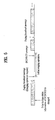
- Figure 3 is a diagram illustrating an example of an operation of a DCD/UCD transmission offset of Tables 13 and 14.
- the paging broadcast message can indicate an exact time (or frame) of when the DCD/UCD message is to be included in the transmission of the paging broadcast message. Therefore, the corresponding mobile stations can receive the DCD/UCD messages during the paging unavailable interval.
- a DCD/UCD transmission offset can be used, instead of the DCD/UCD transmission indication to indicate whether the DCD/UCD message is transmitted during the paging unavailable interval.
- the DCD/UCD transmission indication of Table 12 is removed or not used in the paging broadcast message.
- the DCD/UCD transmission offset TLV parameter can be included in the paging broadcast message, and the MS stays awake or enter paging unavailable interval until the paging broadcast message containing the DCD/UCD message is received, even after expiration of the listening interval.
- the MS maintains normal power saving operation mode without staying awake.
- Figure 4 is a diagram illustrating an example of a paging cycle synchronized to a DCD/UCD transmission cycle.
- the paging cycle of the power saving mode and the DCD/UCD message transmission cycle i.e., DCD/UCD interval
- all mobile stations in the paging listening interval of the power saving mode can receive the DCD/UCD messages during every paging listening interval.
- the features of the embodiments of the present invention can be realized without the proposed operations presented in the embodiments of the present invention.
- Figure 5 is a diagram illustrating an example of an initial ranging operation by the MS according to coding scheme and modulation schemes changes in the BS.
- the DCD/UCD message has to be received by the MS.
- the BS can transmit the DCD/UCD message to the MS that is in the power saving mode.
- the MS After the MS receives the ranging request message via the paging broadcast message, the MS performs following ranging operation. First, the MS receives the DCD/UCD message, followed by transmitting a ranging request (i.e., RNG-REQ) message, and thereafter receives a ranging response (i.e., RNG-RSP) message. After the ranging response message is received, the MS maintains the power saving mode. That is, if the MS receives and successfully decodes the DCD message and the UCD message and also receives the ranging response message, then the MS enters the paging unavailable interval to maintain the power saving mode.
- a ranging request i.e., RNG-REQ
- RNG-RSP ranging response
- Figure 6 is diagram illustrating an example of an operation using a frame number instead of the DCD/UCD transmission offset of Table 14.
- a frame to transmit the DCD/UCD can be indicated, thus able to decrease the size of the transmission message.
- Table 15 is an example of using a frame number in a TLV format in the paging broadcast message.
- Table 15 is an example of using a frame number in a TLV format in the paging broadcast message.
- Table 15 is an example of using a frame number in a TLV format in the paging broadcast message.
- Table 15 Name Type Length Value
- DCD/UCD Transmission frame TBD 8 bits This value may be included in MOB_PAG-ADV message when DCD Transmission Indication in the message is set to 1, and indicates the least significant eight bits of the frame number of the next DCD transmission.
- UCD Transmission frame TBD 8 bits This value may be included in MOB_PAG-ADV message when UCD Transmission Indication in the message is set to 1, indicates the least significant eight bits of the frame number of the next UCD transmission.
- Table 16 illustrates another example of the common downlink notification (i.e., Common_DL_Notification_IE) DL-MAP IE to the example of Table 14.
- Table 17 is an example of a Broadcasts Control Pointer IE included in the DL-MAP message if the frame number is used instead of the DCD/UCD transmission offset.
- DCD_UCD Configuration Change Counter 4 bits A composite configuration change counter incremented for each change in either DCD or UCD.
- the MS receives and decodes the DCD/UCD message transmitted from the BS even after the MS has entered the paging unavailable interval.
- the DCD/UCD message can be received by synchronizing the downlink frame with the transmission frame indicated in the Broadcast Control Pointer IE. That is, the MS awakes up or exits the paging unavailable interval during the frame. After the UCD/DCD messages are received, the MS returns to or enters the paging unavailable interval for maintaining the power saving mode.
- the MS fails to successfully decode the DCD/UCD message and if the BS does not transmit the DCD message or the UCD message at the specified transmission frame, the MS has to receive and decode all subsequent downlink frames to receive the DCD message or the UCD message with updated or changed status information or parameters. After the UCD/DCD messages are received, the MS returns to or enters the paging unavailable interval for maintaining the power saving mode.
- the BS can transmit information which includes that the message is to be transmitted via either the paging broadcast message, the DCD/UCD transmission indication of the common downlink notification DL-MAP IE, or the DCD/UCD transmission offset bitmap during the next paging unavailable interval.
- the BS can indicate the lower 8 bits of the frame number, through which actual transmission is to take place, using the DCD transmission frame and the UCD transmission frame.
- the MS can receive the DCD/UCD message transmitted to the corresponding frame even during the paging unavailable interval.
- the DCD transmission indication, the UCD transmission indication, and the DCD/UCD transmission offset bitmap has a length of 1 bit, 1 bit, and 2 bits, respectively.
- information contained in the DCD transmission indication, the UCD transmission indication, and the DCD/UCD transmission offset bitmap can be represented by using a flag, which has a length of 2 bits.
- Table 18 is an example illustrating a flag.
- a flag can be used to indicate whether the DCD/UCD is scheduled during the paging unavailable interval. For example, if the flag value or parameter is '00,' this indicates that there is no DCD/UCD transmission scheduled during the next paging unavailable interval. If the parameter of the flag is '01,' this indicates that only the DCD is scheduled for transmission. Moreover, if the flag parameter is 10,' this indicates that only the UCD is scheduled for transmission. Lastly, if the flag parameter is ' 11,' then this indicates that both the DCD and the UCD is scheduled for transmission.
- an operation of updating channel information can be performed by an apparatus in a power saving mode.
- Figure 7 is an example of an apparatus in a power saving mode which is used to update channel information.
- the apparatus includes a receiver 10 which receives status information, such as the DCD message and/or the UCD message, of a first channel descriptor and transmission frame information which includes when the first channel descriptor is scheduled to be transmitted.
- the apparatus further includes a comparator 20 which is used to compare status information of the first channel descriptor with status information of a second channel descriptor.
- the second channel descriptor is stored in a memory 30 of the MS.
- the receiver 10 also receives the first channel descriptor according to the transmission frame information if the compared status information from the comparator 20 are different.
Abstract
Description
- The present invention relates to a method of updating channel information, and more particularly, to a method of updating channel information by a mobile station that is in power saving mode.
- In a Broadband Wireless Access System, an operation of a power saving mode is as follows. A paging zone refers to all the paging areas covered by a plurality of base stations. Here, all the base stations in the same paging zone share a same paging cycle (i.e., Paging_Cycle) and a same paging offset (i.e., Paging_Offset).
- In the system, a mobile station (MS) can request to enter a power saving mode from the base station (BS). The BS can then permit the MS to enter the power saving mode by transmitting its paging group identification (i.e, Paging_Group_ID) and the paging cycle and the paging offset, both corresponding to the paging group ID. Upon receiving the paging group ID, the corresponding paging cycle, and the corresponding paging offset, the MS can then enter the power saving mode.
- During the power saving mode, the MS receives a broadcast message in a form of a paging broadcast message (i.e., MOB-PAG-ADV) from the BS at specified paging cycle. From the paging broadcast message, the MS can determine whether to maintain or terminate the power saving mode.
- If a situation arises where the MS has to send uplink traffic to the BS, the MS can terminate the power saving mode anytime. Conversely, if a situation arises where the MS, which is in the power saving mode, has to receive downlink traffic from the BS, the BS sends the paging broadcast message to instruct the MS to terminate the power saving mode.
- Alternatively, if the MS, which is in a power saving mode fails to receive the paging broadcast message at the specified time as a result of moving to another paging zone or by failure to synchronize, then the MS has to terminate the power saving mode.
- Accordingly, the present invention is directed to a method of updating channel information by a mobile station that is in power saving mode that substantially obviates one or more problems due to limitations and disadvantages of the related art.
- An object of the present invention is to provide a method of updating channel information by a mobile station that is in power saving mode.
- Another object of the present invention is to provide a method of providing channel information by a base station to a mobile station that is in power saving mode.
- A further object of the present invention is to provide an apparatus for updating channel information by a mobile station that is in power saving mode.
- Additional advantages, objects, and features of the invention will be set forth in part in the description which follows and in part will become apparent to those having ordinary skill in the art upon examination of the following or may be learned from practice of the invention. The objectives and other advantages of the invention may be realized and attained by the structure particularly pointed out in the written description and claims hereof as well as the appended drawings.
- To achieve these objects and other advantages and in accordance with the purpose of the invention, as embodied and broadly described herein, a method of updating channel information by a mobile station (MS) that is in power saving mode includes the MS which receives status information of a first channel descriptor and a transmission frame information which includes when the first channel descriptor is to be transmitted. Furthermore, the MS compares status information of the first channel descriptor with status information of a second channel descriptor. Here, the second channel descriptor is stored in the MS. Lastly, if the compared status information are different, the MS receives the first channel descriptor according to the transmission frame information.
- In another aspect of the present invention, a method of providing channel information by a base station (BS) to a mobile station (MS) that is in power saving mode, includes the BS which transmits status information of a first channel descriptor and transmission frame information which includes when the first channel descriptor is to be transmitted. Moreover, the BS transmits the first channel descriptor according to the transmission frame information.
- Yet, in another aspect of the present invention, an apparatus for updating channel information where the apparatus is in power saving mode. The apparatus includes a receiver for receiving status information of a first channel descriptor and a transmission frame information which includes when the first channel descriptor is to be transmitted. In addition, the apparatus includes a comparator for comparing status information of the first channel descriptor with status information of a second channel descriptor. Here, the second channel descriptor is stored in a memory of the MS. Lastly, the receiver is used to receive the first channel descriptor according to the transmission frame information, if the compared status information from the comparator are different
- Another aspect of the present invention includes a method of updating channel information by a mobile station (MS) that is in power saving mode. In the method, the MS receives status information of a channel descriptor and a transmission frame information which includes when the channel descriptor is to be transmitted. Furthermore, the MS recognizes a change in the status information of the channel descriptor since a last decoded status information. Lastly, the MS receives the channel descriptor according to the transmission frame information.
- In another aspect of the present invention, a method of updating channel information by a mobile station (MS) that is in power saving mode includes the MS which receives a transmission frame information which includes a specified frame at which a channel descriptor is to be transmitted. Moreover, the MS recognizes the specified frame for receiving the channel descriptor which contains information different from channel descriptor information stored in the MS. Lastly, the MS receives the channel descriptor at the specified frame.
- It is to be understood that both the foregoing general description and the following detailed description of the present invention are exemplary and explanatory and are intended to provide further explanation of the invention as claimed.
- The accompanying drawings, which are included to provide a further understanding of the invention and are incorporated in and constitute a part of this application, illustrate embodiment(s) of the invention and together with the description serve to explain the principle of the invention. In the drawings;
-
FIG. 1 is a diagram illustrating an example of an operation of a power saving mode according to updated status information of a DCD/UCD; -
FIG. 2 illustrates an example of a transmission operation of a paging broadcast message or a common downlink notification DL-MAP IE; -
FIG. 3 is a diagram illustrating an example of an operation of a DCD/UCD transmission offset; -
FIG. 4 illustrates is a diagram illustrating an example of a paging cycle synchronized to a DCD/UCD transmission cycle; -
FIG. 5 is a diagram illustrating an example of an initial ranging operation by the MS according to coding scheme and modulation schemes changes in the BS; and -
FIG. 6 is diagram illustrating an example of an operation using a frame number instead of a DCD/UCD transmission offset. -
FIG. 7 is a diagram illustrating an example of an apparatus in a power saving mode which updates channel information. - Reference will now be made in detail to the preferred embodiments of the present invention, examples of which are illustrated in the accompanying drawings. Wherever possible, the same reference numbers will be used throughout the drawings to refer to the same or like parts.
- In connection with the present invention, a more detailed description of a power saving mode as well as a Downlink Channel Descriptor (DCD) and an Uplink Channel Descriptor (UCD) is provided in an IEEE 802.16e specification document.
- As described above, the MS in a power saving mode receives a paging broadcast message (i.e., MOB_PAG_ADV), which is transmitted according to a paging cycle, from the BS in the paging zone. Here, the power saving mode can be an idle mode or a sleep mode.
- Table 1 represents an example of a Paging-Group-Action message for forming a paging zone. Here, the base stations can transmit messages between each other via a wired connection (e.g., a cable).
[Table 1] Field Size Notes Paging-group-action Message Format () { Message Type 8 bits Sender BS-ID 48 bits Base station unique identifier(Same number as that broadcasted on the DL-MAP message) Target BS-ID 48 bits Base station unique identifier(Same number as that broadcasted on the DL-MPA message) Time Stamp 32 bits Number of millisecond since midnight GMT (set to 0xffffffff on the DL-MAP message) Action 4 bits 0-Assign target BS to paging group
1-Remove target BS from paging group
2-Query (to which paging group target BS belongs?)
3-Information (to which paging group sender BS belongs?)NumRecord 4 bits Number of paging group-ID records For(j=0; j<Num Record; j++) { Paging-group-ID 16 bits Paging-group-ID PAGING_CYCLE 16 bits Cycle in which the paging message in transmitted within the paging group PAGING_OFFSET 8 bits MSS PAGING OFFSET parameter } Security field TBD A mean to authenticate this message CRC field 32 bits IEEE CRC-32 } - The messages transmitted between the base stations can be used for following four purposes based on the indication of action bits. That is, if an action field indicates that Action = 0, then the message can include a command to assign a target BS to a specified paging group. Here, the target BS is the BS that receives the message from another BS. On the contrary, if the action field indicates that Action = 1, then the message can include a command to remove or exclude the target BS from a specified paging group. Furthermore, if the action field indicates that Action = 2, then the message can include a query as to which paging group the target BS belongs. Lastly, if the action field indicates that Action = 3, then the message can include information as to which paging group a sender BS belongs. Here, the sender BS is the BS that transmits the message from another BS.
- Because one BS can belong to more than one paging group, a paging-group-action message can include information on a plurality of paging groups. In addition, the base stations can gain access to the paging cycle and the paging offset of each paging zone from the paging-group-action, which is shared by base stations.
- Table 2 is an example of a deregistration request message (i.e., DREG_REQ), which is a message by the MS to request to enter a power saving mode.
[Table 2] Syntax Size Notes DREG-REQ_Message_Format () { Management Message Type=29 8 bits 0x00=SS de-registration request from BS and network
0x01=request for MS deregistration from Serving BS invitation of MS paging
Availability Mode
0x02-0xFF=reservedDe-registration Request Code 8 bits Only valid if De-Registration Request
Code=0x01Paging Cycle Request 16 bits TLV encoded parameter variable } - According to Table 2, the MS can set a De-Registration Request Code of the DREG_REQ message to '0x01,' and request for deregistration from a serving BS. That is, the MS requests the BS for permission to enter a power saving mode. Here, the serving BS refers to the BS which sends paging information to mobile stations in its coverage area. In addition, the MS can send its preferred paging cycle in the DREG_REQ message.
- Table 3 is an example of a deregistration command message (i.e., DREG_CMD).
[Table 3] Syntax Size Notes DREG-REQ_Message_Format () { Management Message Type=29 8 bits Action Code 8 bits TLV encoded parameter variable } - Using an 'Action Code' of the DREG_CMD message, the BS can permit the MS to enter a power saving mode (e.g., Action Code = 0x05), have the MS request again the request to enter a power saving mode (e.g., Action Code = 0x06), or have the MS wait (or cease the requests to enter the power saving mode) until the BS transmits the DREG_CMD message (e.g., Action Code = 0x07).
- Table 4 is an example of action codes of a deregistration command (i.e., DREG_CMD) message.
[Table 4] Action Code Action 0x00 SS shall leave the current channel and attempt to access another channel 0x01 SS shall listen to the current channel but shall not transmit until an RES-CMD message or DREG_CMD with Action Code 0x00 is received 0x02 SS shall listen to the current channel but only transmit on the Basic, Primary Management and Secondary Management Connections. 0x03 SS shall return to normal operation and may transmit on any of its active connections. 0x04 SS shall terminate current Normal Operation with the BS; the BS shall transmit this action code only in response to any SS DREG-REQ 0x05 required MSS de-registration from Serving BS and request initiation of MSS Idle Mode 0x06 The MSS may retransmit the DREG-REQ message after the time duration (REQ-duration) given by 0x07 The MSS shall not retransmit the DREG-REQ message and shall wait the DREG_CMD message 0x08-0xFF Reserved - By using a type-length-field (TLV) parameters, which can be selectively included in the DREG_CMD message, a paging group ID, a paging cycle, and a paging offset can be transmitted to the MS. The paging group ID, the paging cycle, and the paging offset must be kept (unchanged) while the corresponding MS is in the power saving mode. After the MS enters the power saving mode, the MS receives a paging broadcast (i.e., MOB-PAG-ADV) message at specified paging cycle(s) and at specified paging offset. Based on the paging broadcast message, the MS can remain in or terminate the power saving mode.
- Table 5 represents an example of a paging broadcast (i.e., MOB-PAG-ADV) message.
[Table 5] Syntax Size Notes MOB_PAG_ADV_Message_Format () { Management Message Type =62 8 bits Num_Paging Group IDs 8 bits Number of Paging Group IDs in this message For(i=0; i<Num_Pagin_GroupIDs; i++){ Paging Group ID 8 bits } For(j=0; j<Num_MACs; j++) { Number of MSS MAC Addresses in message can be determined from the length of the message(found in the generic MSS MAC Address hash 24 bits Action Code 2 bits Paging action instruction to MSS
00=No Action Required
01=Performing Ranging to establish location and acknowledge message
10=Enter Network
11=reservedReserved 6 bits } - In the Broadband Wireless Access System, the MS has to receive a Downlink Channel Descriptor/Uplink Channel Descriptor (DCD/UCD) for network entry when the MS turns on power and for network re-entry in performing operations such as handover.
- Table 6 is an example of a Downlink Channel Descriptor (DCD).
[Table 6] Syntax Size Notes DCD_Manage_Format () { Management Message Type= 1 8 bits Downlink Channel ID 8 bits Configuration Change Count 8 bits TLV Encoded information for the overall channel variable TLV specific Begin PHY Specification Section { for(i=1; i<=n; i++) { For each downlink burst profile 1 to nDownlink_Burst_Profile PHY specific } } } - Table 7 is an example of an Uplink Channel Descriptor (UCD).
[Table 7] Syntax Size Notes UCD_Manage_Format () { Management Message Type=0 8 bits Configuration Change Count 8 bits Ranging Backoff Start 8 bits Ranging Backoff End Ranging Backoff Start Ranging Backoff End TLV Encoded information for the overall channel variable TLV specific Begin PHY Specification Section{ for(i=1; i<=n; i++){ For each downlink burst profile 1 to nUplink_Burst_Profile PHY specific } } } - The DCD/UCD messages are physical layers parameters which apply to each allocated burst intervals for downlink and uplink. Moreover, the DCD/UCD messages include information on a modulation scheme and a Forward Error Correction (FEC) code type. Furthermore, using the DCD/UCD messages, necessary parameters (e.g., K and R values of a RS code) are provided according to various FEC code types. These types of parameters can be provided via Burst Profile. Here, the Burst Profile is provided for each Uplink Interval Usage Code (UIUC) and Downlink Interval Usage Code (DIUC) from the UCD and the DCD.
- The status information or the parameters and setting that can be included in the DCD/UCD messages can vary depending on the physical layers. As such, the parameters or settings provided in Tables 8 and 9 can be included in a 'TLV Encoded Information for the overall channel' field of each message.
- Table 8 is an example of parameters included in a 'TLV Encoded Information for the overall channel' field of the DCD message in an Orthogonal Frequency Division Multiple Access (OFDMA).
[Table 8] Name Type (byte) Length Value (variable length) PHY scope Downlink_Burst_Profile 1 May appear more once. The length is the number of bytes in the overall object, including embedded TLV items All BS EIRPS 2 2 Signed in units of 1 dBM All Frame Duration 3 4 The number of PSs contained in a Burst FDD or TDD frame.
Required only for frame downlinkssc PHY Type 4 1 The PHY Type to be used sc Power adjustment rule 5 1 0=Preserve Peak Power
1=Preserve Mean Power
Describe the power adjustment rule when performing a transition from one burst profile to another.SC, SCa Channel Number 6 1 Downlink channel number as defined in 8.5. Used for license-exempt operation only. SCa, OFDM, OFDMA TTG 7 1 TTG (in PSs) SCa, OFDM, OFDMA RTG 8 1 RTG (in PSs) SCa, OFDM, OFDMA RSSIR_max 9 2 Initial Ranging Max. Received Signal Strength at BS Signal in units of 1 dBm All Channel Switch
Frame Number 10 3 Channel switch frame number as defined in 6. 3.
15. 7, Used for lisense-exempt operation onlySCa, OFDM, OFDMA Frequency 12 4 Downlink center frequency(kHz) All BS ID 13 6 Base Station ID SCa, OFDM, OFDMA Frame Duration Code 14 1 The duration of the frame. The frame duration code values are specified in Table 230. OFDM Frame Number 15 3 The number of the frame containing the DCD message. OFDM [Table 9] Name Type (byte) Length Value Initial ranging codes 150 1 Number of initial ranging CDMA codes. Possible values are 0-225. Periodic ranging codes 151 1 Number of periodic ranging CDMA codes. Possible values are 0-225. Bandwidth request codes 152 1 Number of bandwidth request codes. Possible values are 0-225. Periodic ranging backoff start 153 1 Initial backoff window size for periodic ranging contention, expressed as a power of 2. Range:0-15(the highest order bits shall be unused and set to 0). Periodic ranging backoff end 154 1 Final backoff window size for periodic ranging contention, expressed as a power of 2. (the highest order bits shall be unused and set to 0). Start of ranging codes group 155 1 Indicates the starting number, S, of the group of codes used for this uplink. All the ranging codes used on this uplink will be between S and ((S+N+M+L)mod256). Where, N is the number of initial-ranging codes M is the number of periodic-ranging codes L is the number of bandwidth-request codes The range of value is 0≤S≤255 Permutation base 156 1 Determine the UL_IDcell parameter for the subcarrier permutation to be used on this uplink channel. UL allocated sub-channels bitmap 157 9 This is a bitmap describing the sub-channels allocated to the segment in the UL, when using uplink PUSC permutation. The LSB of the first byte shall correspond to subchannel 0. For amy bit that is not set, the corresponding subchannel shall not be used by the SS on that segment. - In the system, the DCD/UCD messages are not limited to settings or parameters contained in Tables 8 and 9. In other words, the DCD/UCD messages can include other information besides the information listed in Tables 8 and 9.
- As shown in Table 6 - Table 9, the DCD/UCD message contains large volumes of information. As such, it would be inefficient for the MS to decode every DCD/UCD messages received. Furthermore, the DCD/UCD message of Tables 6 and 7 includes Configuration Change Count parameter. Here, the Configuration Change Counter can increase by increments of one (1) if the value(s) contained in the current DCD/UCD message is (are) different from the value(s) contained in a previous DCD/UCD message. In other words, if the MS recognizes that there is change in status information of a received DCC/UCD from status information of the DCD/UCD stored in the MS, then the Configuration Change Counter increases by a specified increment. The settings or parameters can also be referred to as status information.
- As discussed above, lengths of the DCD/UCD messages are not only long but information contained in the DCD/UCD messages are relatively constant. That is, the DCD/UCD messages generally do not change often. Therefore, the DCD/UCD messages are not transmitted in every frame, and more realistically, the DCD/UCD messages are transmitted periodically with a maximum period of 10 seconds, for example.
- As for the BS, the BS transmits the DCD/UCD message containing a new status information (or new values) after waiting a specified time period so that all mobile stations in its cell coverage area can receive the DCD/UCD message. Here, the Configuration Change Counter included in the DCD/UCD message increases by an increment of 1). Thereafter, the BS applies the updated or changed status information of the DCD/UCD to the burst profile of the uplink/downlink frame(s).
- As shown in Table 10 and Table 11, the updated status information can be provided to the MS by using a DL-MAP message and a 'DCD/UCD Count' field included in an UL-MAP message. Since the DL-MAP message and the UL-MAP message are encoded with predefined values of the physical layer, the MS can decode the changed status information in the DCD message and the UCD message.
- Table 10 is an example of a DL-MAP.
[Table 10] Syntax Size Notes DL-MAP_Message_Format () { Management Message Type=2 8 bits PHY Synchronization Field variable See appropriate PHY specification DCD Count 8 bits Base Station ID 48 bits Begin PHY Specific Section { See applicable PHY section for(i=1; j<=n; i++) { For each DL- MAP element 1 to nDL-MAP_IE () variable See corresponding PHY specification } } if! (byte boundary) { Padding Nibble 4 bits Padding to reach byte boundary } } - Table 11 is an example of an UL-MAP.
[Table 11] Syntax Size Notes UL-MAP _Message_Format () { Management Message Type=3 8 bits Uplink Channel ID 8 bits UCD Count 8 bits Allocation Start Time 32 bits Begin PHY Specific Section{ See applicable PHY section for(i=1, i<=n, i++) { For each US- MAP element 1 to nUL-MAP_IE () variable See corresponding PHY specification } Padding to reach byte boundary } if! (byte boundary) { Padding Nibble } } - After the MS receives an updated DL-MAP/UL-MAP having status information different from that of the previous status information, the MS uses the status information (or values) included in the last received DCD/UCD message to decode the bursts included in the corresponding DL-MAP/UL-MAP.
-
Figure 1 is a diagram illustrating an example of an operation of a power saving mode according to updated status information of a DCD/UCD. - If the paging broadcast message is configured to be transmitted using a predetermined coding and modulation schemes, then the MS in the power saving mode can still receive the paging broadcast message even if no DCD/UCD message is received.
- However, if the predetermined coding and modulation schemes are not used, the MS in the power saving mode does not receive a DCD/UCD message, and the BS changes (or updates) the coding and modulation schemes, the MS has to terminate the power saving mode since the MS is unable to decode the paging broadcast message. Alternatively, if the MS belongs to the same paging group but moves to a cell using different coding and modulation schemes, the MS has to terminate the power saving mode since the MS cannot decode the paging broadcast message. Alternatively, if the MS in the power saving mode does not receive any DCD/UCD messages, the re-entry to the network by the MS can take additional time since the MS has to receive the DCD/UCD message in order to receive the current coding and modulation schemes. As such, it seems necessary and practical for the MS in the power saving mode to be able to receive the DCD/UCD messages.
- If the MS is configured to receive the DCD/UCD messages while in the power saving mode, the MS in the power saving mode can decode the downlink frame during a specified cycle. Furthermore, if the DCD/UCD status information (or values) are updated or changed during a Paging Unavailable Interval or if the MS has moved to another cell within the same paging group, the MS has to continuously receive and decode all subsequent downlink frames until the new DCD/UCD message with updated or changed status information is received. Here, the Paging Unavailable Interval is an interval or a period in which the MS does not receive and decode any downlink frames in order to conserve power. Moreover, as discussed above, the DCD/UCD message contains a Configuration Change Counter which is independently managed by each BS. For example, a first BS and a second BS belong to the same paging group. However, since the Configuration Change Counters independent of each other BS, the Counter of the first BS could be indicating 2 while the Counter of the second BS could be indicating 5. In addition, since the transmission cycle of the DCD/UCD message can be long (e.g., up to 10 seconds per cycle), the power consumption of the MS in the power saving mode can be significant.
- Table 12 is an example of a paging broadcast message (i.e., MOB-PAG-ADV).
[Table 12] Syntax Size Notes MOB_PAG-ADV_Message_Format () { Management Message Type =?? 8 bits Num_Paging Group IDs 8 bits Number of Paging Group IDs in this message For(i=0; i<Num_Paging_Group_IDs; i++) { Paging Group ID 8 bits } For(j=0; j<Num_MACs; j++) { MSS MAC Address hash 24 bits Action Code 2 bits Paging action instruction to MSS
00=No Action Required
01=Perform Ranging to establish location and acknowledge message
10=Enter Network
11=reservedReserved 6 bits } DCD Transmission Indicator 1 bit Indicates whether DCD message is included in the next Paging Unavailable Interval or not.
0=Not included
1=IncludedDCD Transmission Indicator 1 bit Indicates whether UCD message is included in the next Paging Unavailable Interval or not.
0=Not included
1=IncludedTLV Encoded Information variable TLV Specific Reserved Padding bits to ensure octet aligned. } - The paging broadcast message of Table 12 is different from the paging broadcast message of Table 5 in that the paging broadcast message of Table 12 includes a DCD/UCD Transmission Indication to determine whether transmission of the DCD/UCD message is scheduled during the Paging Unavailable Interval.
- If the DCD/UCD Transmission Indication is set at '1,' a DCD/UCD Transmission Offset can be provided in a form of TLV in the paging broadcast message, as shown in Table 13.
[Table 13] Name Type Length Value DCD/UCD Transmission offset TBD 16 bits This value may be included in MOB_PAG-ADV message when DCD Transmission Indication in the message is set to 1, and indicates the number of frames left for the next transmission of DCD message. UCD Transmission offset TBD 16 bits This value may be included in MOB_PAG-ADV message when UCD Transmission Indication in the message is set to 1, and indicates the number of frames left for the next transmission of UCD message. - The DCD/UCD Transmission Indication of the paging broadcasts message of Table 12 and the DCD/UCD Transmission Offset of Table 13 can be in a form of a common downlink notification information element (i.e., Common_DL_Notification_IE) DL-MAP message as provided in Table 14. The common downlink notification information element can be included in a DL-MAP IE which is transmitted during the paging cycle. The DCD/UCD transmission offset bitmap is used to identify whether the offset is for the DCD or UCD.
- Table 14 is an example of a common downlink notification DL-MAP message.
[Table 14] Syntax Size Notes Common_DL_Notification_IE () { Extended UIUC 4 bits Length 4 bits Length in Bytes DCD Transmission Indication 1 bit Indicates if DCD message is included in the next Paging Unavailable Interval or not.
0=Not included
1=IncludedUCD Transmission Indication 1 bit Indicates if UCD message is included in the next Paging Unavailable Interval or not.
0=Not included
1=IncludedDCD/UCD Transmission offset bitmap 2 bits This bitmap indicates;
00: No DCD/UCD offset is included,
01: DCD offset is included.
10: UCD offset is included.
11: DCD/UCD offsets are included.reserved 4 bits Padding for byte alignment DCD Transmission offset 16 bits This value may be included when DCD Transmission Indication set to 1, and indicates the number of frames left for the next transmission of DCD message. UCD Transmission offset 16 bits This value may be included when UCD Transmission Indication set to 1, and indicates the number of frames left for the next transmission of UCD message. } -
Figure 2 illustrates an example of a transmission operation of a paging broadcast message of Table 12 or a common downlink notification DL-MAP IE of Table 14. Referring toFigure 2 , the MS that is in the power saving mode identifies a change in the Configuration Change Counter included in the DCD/UCD message from the paging broadcast message received during the paging listening interval. Once the change is identified, the MS that is in the power saving mode has to obtain the DCD/UCD transmission indication parameters of the paging broadcast message which is received during the paging listening interval. - If the DCD/UCD transmission identification parameter is `0,' the MS knows that no DCD/UCD message transmitted during the next paging unavailable interval. Then the MS maintains normal power saving mode instead of waiting to receive the UCD/DCD message until the next paging listening interval.
- On the contrary, the DCD/UCD transmission identification parameter set to '1' signifies that the DCD/UCD message is to be transmitted during the next paging unavailable interval. As such, the MS does not return to paging unavailable interval even after expiration of the listening interval until the MS receives the DCD/UCD message. In other words, the MS stays awake (maintains listening interval) until the DCD/UCD message is received. Upon receipt, the MS returns to the paging unavailable interval.
-
Figure 3 is a diagram illustrating an example of an operation of a DCD/UCD transmission offset of Tables 13 and 14. InFigure 3 , the paging broadcast message can indicate an exact time (or frame) of when the DCD/UCD message is to be included in the transmission of the paging broadcast message. Therefore, the corresponding mobile stations can receive the DCD/UCD messages during the paging unavailable interval. - As another embodiment of the present invention, a DCD/UCD transmission offset can be used, instead of the DCD/UCD transmission indication to indicate whether the DCD/UCD message is transmitted during the paging unavailable interval. Here, the DCD/UCD transmission indication of Table 12 is removed or not used in the paging broadcast message. However, if the situation calls for the BS to transmit a DCD/UCD message during the paging unavailable interval, the DCD/UCD transmission offset TLV parameter can be included in the paging broadcast message, and the MS stays awake or enter paging unavailable interval until the paging broadcast message containing the DCD/UCD message is received, even after expiration of the listening interval. Alternatively, if the BS does not transmit the DCD/UCD message during the next paging unavailable interval, the DCD/UCD transmission offset TLV parameter is not included in the paging broadcast message. After the MS receives this paging broadcast message absent the DCD/UCD transmission offset TLV parameter and recognizes that the DCD/UCD message is not expected to be transmitted during the next paging unavailable interval. Therefore, the MS maintains normal power saving operation mode without staying awake.
-
Figure 4 is a diagram illustrating an example of a paging cycle synchronized to a DCD/UCD transmission cycle. As illustrated inFigure 4 , if the paging cycle of the power saving mode and the DCD/UCD message transmission cycle (i.e., DCD/UCD interval) are synchronized, all mobile stations in the paging listening interval of the power saving mode can receive the DCD/UCD messages during every paging listening interval. As such, the features of the embodiments of the present invention can be realized without the proposed operations presented in the embodiments of the present invention. -
Figure 5 is a diagram illustrating an example of an initial ranging operation by the MS according to coding scheme and modulation schemes changes in the BS. First, to perform initial ranging operation, the DCD/UCD message has to be received by the MS. Thereafter, if the MS is directed to perform initial ranging operation, then the BS can transmit the DCD/UCD message to the MS that is in the power saving mode. - After the MS receives the ranging request message via the paging broadcast message, the MS performs following ranging operation. First, the MS receives the DCD/UCD message, followed by transmitting a ranging request (i.e., RNG-REQ) message, and thereafter receives a ranging response (i.e., RNG-RSP) message. After the ranging response message is received, the MS maintains the power saving mode. That is, if the MS receives and successfully decodes the DCD message and the UCD message and also receives the ranging response message, then the MS enters the paging unavailable interval to maintain the power saving mode.
-
Figure 6 is diagram illustrating an example of an operation using a frame number instead of the DCD/UCD transmission offset of Table 14. If the DCD/UCD transmission offset is used, the transmission offset has to be 16 bits considering a 16-bit maximum paging cycle of the power saving mode and a 10-second maximum DCD/UCD transmission cycle (e.g., 2000 frames where 1 frame = 5milliseconds). As for using the frame number, even if lower 8 bits are used, a frame to transmit the DCD/UCD can be indicated, thus able to decrease the size of the transmission message. - If the frame number is used instead of the DCD/UCD transmission offset, information listed in Table 15 can be additionally included to the paging broadcast message of Table 5 in a TLV format. Table 15 is an example of using a frame number in a TLV format in the paging broadcast message.
[Table 15] Name Type Length Value DCD/UCD Transmission frame TBD 8 bits This value may be included in MOB_PAG-ADV message when DCD Transmission Indication in the message is set to 1, and indicates the least significant eight bits of the frame number of the next DCD transmission. UCD Transmission frame TBD 8 bits This value may be included in MOB_PAG-ADV message when UCD Transmission Indication in the message is set to 1, indicates the least significant eight bits of the frame number of the next UCD transmission. - As described above, if the frame number is used instead of the DCD/UCD transmission offset, Table 16 illustrates another example of the common downlink notification (i.e., Common_DL_Notification_IE) DL-MAP IE to the example of Table 14.
[Table 16] Syntax Size Notes Common_DL_Notification_IE () { Extended UIUC 4 bits Length 4 bits Length of Bytes DCD Transmission Indication 1 bit Indicates if DCD message is included in the next Paging Unavailable Interval or not.
0=Not included
1=IncludedUCD Transmission Indication 1 bit Indicates if UCD message is included in the next Paging Unavailable Interval or not.
0=Not included
1=IncludedDCD/UCD Transmission offset bitmap 2 bits This bitmap indicates;
00: No DCD/UCD offset is included.
01: DCD offset is included.
10: UCD offset is included.
11: DCD/UCD offsets are included.reserved 4 bits Padding for byte alignment DCD Transmission frame 8 bits This value may be included when DCD Transmission Indication in the message is set to 1, and indicates the least significant eight bits of the frame number of the next DCD transmission. UCD Transmission flame 8 bits This value may be included when UCD Transmission Indication in the message is set to 1, indicates the least significant eight bits of the frame number of the next UCD transmission. } - Table 17 is an example of a Broadcasts Control Pointer IE included in the DL-MAP message if the frame number is used instead of the DCD/UCD transmission offset.
[Table 17] Syntax Size Notes Broadcast Control Pointer IE () { Extended UIUC 4 bits 0x0A Length 4 bits Length of Bytes DCD_UCD Configuration Change Counter 4 bits A composite configuration change counter incremented for each change in either DCD or UCD. DCD_UCD Transmission Frame 8 bits The least significant eight bits of the frame number of the next DCD and/or UCD transmission reserved 4 bits Shall be set to zero } - If a DCD_UCD Configuration Change Counter setting or parameter of the Broadcast Control Pointer IE of Table 17 is different from a DCD_UCD Configuration Change Counter setting or parameter stored in the MS, the MS receives and decodes the DCD/UCD message transmitted from the BS even after the MS has entered the paging unavailable interval. Here, the DCD/UCD message can be received by synchronizing the downlink frame with the transmission frame indicated in the Broadcast Control Pointer IE. That is, the MS awakes up or exits the paging unavailable interval during the frame. After the UCD/DCD messages are received, the MS returns to or enters the paging unavailable interval for maintaining the power saving mode.
- However, if the MS fails to successfully decode the DCD/UCD message and if the BS does not transmit the DCD message or the UCD message at the specified transmission frame, the MS has to receive and decode all subsequent downlink frames to receive the DCD message or the UCD message with updated or changed status information or parameters. After the UCD/DCD messages are received, the MS returns to or enters the paging unavailable interval for maintaining the power saving mode.
- As illustrated in
Figure 6 , if the DCD/UCD message is scheduled to be transmitted during the next paging unavailable interval (e.g., at frame A), the BS can transmit information which includes that the message is to be transmitted via either the paging broadcast message, the DCD/UCD transmission indication of the common downlink notification DL-MAP IE, or the DCD/UCD transmission offset bitmap during the next paging unavailable interval. - Furthermore, the BS can indicate the lower 8 bits of the frame number, through which actual transmission is to take place, using the DCD transmission frame and the UCD transmission frame. Using this scheme, the MS can receive the DCD/UCD message transmitted to the corresponding frame even during the paging unavailable interval.
- As indicated in Table 14 and Table 16, the DCD transmission indication, the UCD transmission indication, and the DCD/UCD transmission offset bitmap has a length of 1 bit, 1 bit, and 2 bits, respectively. Here, information contained in the DCD transmission indication, the UCD transmission indication, and the DCD/UCD transmission offset bitmap can be represented by using a flag, which has a length of 2 bits.
- Table 18 is an example illustrating a flag.
[Table 18] DCD/UCD transmission indication flag 2 bits For each bit location, a value of indicates that DCD and UCD transmission is scheduled during next Paging Unavailable Interval.
Bit 0: DCD transmission during next Paging Unavailable Interval.
Bit 1: UCD transmission during next Paging Unavailable Interval. - As shown in Table 18, a flag can be used to indicate whether the DCD/UCD is scheduled during the paging unavailable interval. For example, if the flag value or parameter is '00,' this indicates that there is no DCD/UCD transmission scheduled during the next paging unavailable interval. If the parameter of the flag is '01,' this indicates that only the DCD is scheduled for transmission. Moreover, if the flag parameter is 10,' this indicates that only the UCD is scheduled for transmission. Lastly, if the flag parameter is ' 11,' then this indicates that both the DCD and the UCD is scheduled for transmission.
- In another embodiment of the present invention, an operation of updating channel information can be performed by an apparatus in a power saving mode.
Figure 7 is an example of an apparatus in a power saving mode which is used to update channel information. InFigure 7 , the apparatus includes areceiver 10 which receives status information, such as the DCD message and/or the UCD message, of a first channel descriptor and transmission frame information which includes when the first channel descriptor is scheduled to be transmitted. The apparatus further includes acomparator 20 which is used to compare status information of the first channel descriptor with status information of a second channel descriptor. Here, the second channel descriptor is stored in amemory 30 of the MS. Furthermore, thereceiver 10 also receives the first channel descriptor according to the transmission frame information if the compared status information from thecomparator 20 are different. - It will be apparent to those skilled in the art that various modifications and variations can be made in the present invention without departing from the spirit or scope of the inventions. Thus, it is intended that the present invention covers the modifications and variations of this invention provided they come within the scope of the appended claims and their equivalents.
-
- 1. A method of updating channel information by a mobile station (MS) that is in power saving mode, the method comprising:
- receiving status information of a first channel descriptor and a transmission frame information which includes when the first channel descriptor is scheduled to be transmitted;
- comparing status information of the first channel descriptor with status information of a second channel descriptor, wherein the second channel descriptor is stored in the MS; and
- if the compared status information are different, receiving the first channel descriptor according to the transmission frame information.
- 2. The method of
embodiment 1, further comprising maintaining power saving mode operation before receiving the first channel descriptor. - 3. The method of
embodiment 1, further comprising maintaining power saving mode operation after receiving the first channel descriptor. - 4. The method of
embodiment 1, further comprising if the compared status information are the same, maintain power saving mode operation without receiving the first channel descriptor. - 5. The method of
embodiment 1, further comprising receiving an indication which indicates whether the first channel descriptor is scheduled to be transmitted in a subsequent paging unavailable interval. - 6. The method of embodiment 5, wherein the idle interval is an interval in which communication between the MS that is in power saving mode and a base station (BS) is unavailable.
- 7. The method of
embodiment 1, wherein the status information of the first channel descriptor and the transmission frame information are received in a paging interval. - 8. The method of embodiment 7, wherein the paging interval is an interval in which a communication is established between the MS that is in power saving mode and a base station (BS).
- 9. The method of
embodiment 1, wherein the first channel descriptor is at least one of an Uplink Channel Descriptor (UCD) and a Downlink Channel Descriptor (DCD). - 10. The method of embodiment 9, wherein the at least one of the UCD and the DCD is a broadcast message.
- 11. The method of
embodiment 1, wherein the second channel descriptor is at least one of an Uplink Channel Descriptor (UCD) and a Downlink Channel Descriptor (DCD). - 12. The method of embodiment 11, wherein the at least one of the UCD and the DCD is a broadcast message.
- 13. The method of
embodiment 1, wherein the first channel descriptor is a broadcast message. - 14. The method of
embodiment 1, wherein the power saving mode is an idle mode. - 15. The method of
embodiment 1, wherein the power saving mode is a sleep mode. - 16. The method of
embodiment 1, wherein the transmission frame information indicates a frame number. - 17. The method of
embodiment 1, further comprising:- receiving and decoding every subsequent frames until the first channel descriptor is successfully decoded if the MS unsuccessfully decodes the first channel descriptor at a transmission frame, wherein the transmission frame corresponds to the frame number provided by the transmission frame information; and
- returning to power saving mode immediately after the successful decoding of the first channel descriptor.
- 18. The method of
embodiment 1, further comprising:- receiving every subsequent frames until the first channel descriptor is successfully received if no first channel descriptor was received by the MS at a transmission frame; and
- returning to power saving mode immediately after the MS successfully receives the first channel descriptor.
- 19. A method of providing channel information by a base station (BS) to a mobile station (MS) that is in power saving mode, the method comprising:
- transmitting status information of a first channel descriptor and transmission frame information which includes when the first channel descriptor is scheduled to be transmitted; and
- transmitting the first channel descriptor according to the transmission frame information.
- 20. The method of embodiment 19, further comprising transmitting an indication which indicates whether the first channel descriptor is scheduled to be transmitted in a subsequent idle interval.
- 21. The method of
embodiment 20, wherein the idle interval is an interval in which communication between the MS that is in power saving mode and the BS is unavailable. - 22. The method of embodiment 19, wherein the status information of the first channel descriptor and the transmission frame information are transmitted in a paging interval.
- 23. The method of embodiment 22, wherein the paging interval is an interval in which a communication is established between the MS that is in power saving mode and the BS.
- 24. The method of embodiment 19, wherein the first channel descriptor is at least one of an Uplink Channel Descriptor (UCD) and a Downlink Channel Descriptor (DCD).
- 25. The method of embodiment 24, wherein the at least one of the UCD and the DCD is a broadcast message.
- 26. The method of embodiment 19, wherein the first channel descriptor is a broadcast message.
- 27. The method of embodiment 19, wherein the status information of the first channel descriptor and the transmission frame information is transmitted if the status information of the first channel descriptor is different from status information of a second channel descriptor, wherein the second channel descriptor is a previously transmitted channel descriptor.
- 28. The method of embodiment 27, wherein the second channel descriptor is at least one of an Uplink Channel Descriptor (UCD) and a Downlink Channel Descriptor (DCD).
- 29. The method of embodiment 28, wherein the at least one of the UCD and the DCD is a broadcast message.
- 30. An apparatus for updating channel information wherein the apparatus is in a power saving mode, the apparatus comprising:
- a receiver for:
- receiving status information of a first channel descriptor and transmission frame information which includes when the first channel descriptor is scheduled to be transmitted, and
- receiving the first channel descriptor according to the transmission frame information, if the compared status information from a comparator are different; and
- comparator for comparing the status information of the first channel descriptor with status information of a second channel descriptor, wherein the second channel descriptor is stored in a memory of the MS.
- a receiver for:
- 31. The apparatus of
embodiment 30, wherein the first channel descriptor is at least one of an Uplink Channel Descriptor (UCD) and a Downlink Channel Descriptor (DCD). - 32. The apparatus of
embodiment 30, wherein the second channel descriptor is at least one of an Uplink Channel Descriptor (UCD) and a Downlink Channel Descriptor (DCD). - 33. A method of updating channel information by a mobile station (MS) that is in power saving mode, the method comprising:
- receiving status information of a channel descriptor and a transmission frame information which includes when the channel descriptor is scheduled to be transmitted;
- recognizing a change in the status information of the channel descriptor since a last decoded status information; and
- receiving the channel descriptor according to the transmission frame information.
- 34. The method of embodiment 33, wherein the transmission frame information indicates a frame number.
- 35. A method of updating channel information by a mobile station (MS) that is in power saving mode, the method comprising:
- receiving a transmission frame information which includes a specified frame at which a channel descriptor is to be transmitted;
- recognizing the specified frame for receiving the channel descriptor which contains information different from channel descriptor information stored in the MS; and
- receiving the channel descriptor at the specified frame.
Claims (14)
- A method for updating channel information of a mobile station, hereinafter called MS, which is in an idle mode, comprising:receiving, by the MS from a base station, hereinafter called BS, a first channel descriptor comprising a configuration change count field, hereinafter called CCC field;receiving, by the MS, a MAP massage comprising a channel descriptor count field and an information element, wherein the information element comprises a transmission frame field indicating a frame in which a second channel descriptor will be transmitted; andreceiving, by the MS, the second channel descriptor by awakening at the frame indicated by the transmission frame field even if the MS is scheduled to be in a paging unavailable interval when a value of the channel descriptor count. field is different from a value of the CCC field which the MS stores.
- A method for updating channel information of a mobile station, hereinafter called MS, which is in an idle mode, comprising:transmitting, by a base station, hereinafter called BS, to the MS, a first channel descriptor comprising a configuration change count field, hereinafter called CCC field;transmitting, by the BS, a MAP massage comprising a channel descriptor count field and an information element, wherein the information element comprises a transmission frame field indicating a frame in which a second channel descriptor will be transmitted; andtransmitting, by the BS, the second channel descriptor at the frame indicated by the transmission frame field even if the MS is scheduled to be in a paging unavailable interval when a value of the channel descriptor count field is different from a value of the CCC field which the MS stores.
- The method according to claims 1 or 2, wherein the paging unavailable interval is an interval during which the MS in the idle mode cannot communicate with the BS.
- The method according to any one claims 1 to 3, wherein the MAP message is transmitted during a paging listening interval which is an interval during which the MS in the idle mode communicates with the BS.
- The method according to any one claims 1 to 4, wherein each of the first channel descriptor and the second channel descriptor is an uplink channel descriptor message and the MAP message is an uplink MAP massage.
- The method according to any one claims 1 to 4, wherein each of the first channel descriptor and the second channel descriptor is a downlink channel descriptor message, and the MAP message is a downlink MAP massage.
- The method according to any one claims 1 to 6, wherein the information element is a broadcast control pointer information element.
- The method according to any one claims 1 to 7, wherein upon successful completion of decoding of the second channel descriptor, the MS immediately returns to the idle mode.
- The method according to any one claims 1 to 8, wherein the information element further comprising a transmission indication field indicating whether the second channel descriptor is scheduled to be transmitted during a next paging unavailable interval.
- An apparatus for supporting of updating channel information in an idle mode, comprising:a receiver (10); anda memory (30),wherein the apparatus receives a first channel descriptor comprising a configuration change count, hereinafter called CCC, field by using the receiver and stores a value of the CCC field using the memory;wherein the apparatus receives a MAP massage comprising a channel descriptor count field and information element which comprises a transmission frame field indicating a frame in which a second channel descriptor is transmitted, by using the receiver during a paging listening interval; andwherein the apparatus receives the second channel descriptor by awakening at the frame indicated by the transmission frame field even if the apparatus is scheduled to be in a paging unavailable interval when a value of the channel descriptor counter field is different from the value of the CCC field stored in the memory.
- An apparatus for supporting of updating channel information, wherein the apparatus is configured to:transmit a first channel descriptor comprising a configuration change count field, hereinafter called CCC field;transmit a MAP massage comprising a channel descriptor count field and an information element during a paging listening interval, wherein the information element comprises a transmission frame field indicating a frame in which a second channel descriptor will be transmitted ; andtransmit the second channel descriptor at the frame indicated by the transmission frame field even if a mobile station, hereinafter called MS, is scheduled to be in a paging unavailable interval when a value of the channel descriptor count field is different from a value of the CCC field which the MS stores.
- The apparatus according to any one claims 10 to 11, wherein each of the first channel descriptor and the second channel descriptor is an uplink channel descriptor message and the MAP message is an uplink MAP massage.
- The apparatus according to any one claims 10 to 11, wherein each of the first channel descriptor and the second channel descriptor is a downlink channel descriptor message, and the MAP message is a downlink MAP massage.
- The apparatus according to any one claims 10 to 13, wherein the information element further comprising a transmission indication field indicating whether the second channel descriptor is scheduled to be transmitted during a next paging unavailable interval.
Applications Claiming Priority (4)
| Application Number | Priority Date | Filing Date | Title |
|---|---|---|---|
| KR20040117275 | 2004-12-30 | ||
| KR20050019841 | 2005-03-09 | ||
| KR1020050131043A KR100885442B1 (en) | 2004-12-30 | 2005-12-27 | Method for updating channel information in Broadband Wireless Access System |
| EP20050823652 EP1832143B1 (en) | 2004-12-30 | 2005-12-30 | Method and apparatus of updating channel information by a mobile station that is in a paging unavailable interval |
Related Parent Applications (2)
| Application Number | Title | Priority Date | Filing Date |
|---|---|---|---|
| EP05823652.2 Division | 2005-12-30 | ||
| EP20050823652 Division-Into EP1832143B1 (en) | 2004-12-30 | 2005-12-30 | Method and apparatus of updating channel information by a mobile station that is in a paging unavailable interval |
Publications (2)
| Publication Number | Publication Date |
|---|---|
| EP2364046A2 true EP2364046A2 (en) | 2011-09-07 |
| EP2364046A3 EP2364046A3 (en) | 2012-02-22 |
Family
ID=36615174
Family Applications (2)
| Application Number | Title | Priority Date | Filing Date |
|---|---|---|---|
| EP20050823652 Not-in-force EP1832143B1 (en) | 2004-12-30 | 2005-12-30 | Method and apparatus of updating channel information by a mobile station that is in a paging unavailable interval |
| EP11004513A Withdrawn EP2364046A3 (en) | 2004-12-30 | 2005-12-30 | A method of updating channel information by a mobile station that is in power saving mode |
Family Applications Before (1)
| Application Number | Title | Priority Date | Filing Date |
|---|---|---|---|
| EP20050823652 Not-in-force EP1832143B1 (en) | 2004-12-30 | 2005-12-30 | Method and apparatus of updating channel information by a mobile station that is in a paging unavailable interval |
Country Status (5)
| Country | Link |
|---|---|
| US (7) | US7630740B2 (en) |
| EP (2) | EP1832143B1 (en) |
| AU (1) | AU2005320380B2 (en) |
| CA (1) | CA2585153C (en) |
| WO (1) | WO2006071096A1 (en) |
Families Citing this family (81)
| Publication number | Priority date | Publication date | Assignee | Title |
|---|---|---|---|---|
| US9020854B2 (en) | 2004-03-08 | 2015-04-28 | Proxense, Llc | Linked account system using personal digital key (PDK-LAS) |
| RU2007127725A (en) | 2004-12-20 | 2009-01-27 | ПРОКСЕНС, ЭлЭлСи (US) | PERSONAL DATA (PDK) AUTHENTICATION BY BIOMETRIC KEY |
| KR101080970B1 (en) * | 2004-12-27 | 2011-11-09 | 엘지전자 주식회사 | Method for Transmitting Decode Information in Broadband Wireless Access System |
| CA2585153C (en) * | 2004-12-30 | 2014-07-08 | Lg Electronics Inc. | A method of updating channel information by a mobile station that is in power saving mode |
| US9113464B2 (en) | 2006-01-06 | 2015-08-18 | Proxense, Llc | Dynamic cell size variation via wireless link parameter adjustment |
| US11206664B2 (en) | 2006-01-06 | 2021-12-21 | Proxense, Llc | Wireless network synchronization of cells and client devices on a network |
| US8428048B2 (en) * | 2006-02-21 | 2013-04-23 | Qualcomm Incorporated | Multi-program viewing in a wireless apparatus |
| US8330866B2 (en) * | 2006-02-21 | 2012-12-11 | Qualcomm Incorporated | Multi-program viewing in a wireless apparatus |
| US7826419B2 (en) | 2006-04-27 | 2010-11-02 | Motorola Mobility, Inc. | Method and system to improve transmission and receipt of channel descriptors |
| US7904718B2 (en) | 2006-05-05 | 2011-03-08 | Proxense, Llc | Personal digital key differentiation for secure transactions |
| US7471942B2 (en) * | 2006-05-18 | 2008-12-30 | Motorola, Inc. | System and method for increased battery saving during idle mode in a wireless communication system |
| WO2008004845A1 (en) * | 2006-07-07 | 2008-01-10 | Samsung Electronics Co., Ltd. | Apparatus and method for reducing volume of resource allocation information message in a broadband wireless communication system |
| US8155674B2 (en) | 2006-08-22 | 2012-04-10 | Research In Motion Limited | Apparatus, and associated method, for dynamically configuring a page message used to page an access terminal in a radio communication system |
| US8284707B2 (en) | 2006-11-07 | 2012-10-09 | Qualcomm Incorporated | Hybrid power-saving mechanism for VoIP services |
| US9269221B2 (en) | 2006-11-13 | 2016-02-23 | John J. Gobbi | Configuration of interfaces for a location detection system and application |
| US20080137632A1 (en) * | 2006-12-06 | 2008-06-12 | Electronics And Telecommunications Research Institute | Apparatus and method of controlling power of terminal in mobile communication system |
| WO2008094017A2 (en) * | 2007-02-02 | 2008-08-07 | Lg Electronics Inc. | Method of transmitting and receiving a message associated with power saving mode in a wireles communication system |
| KR101405936B1 (en) | 2007-02-02 | 2014-06-17 | 엘지전자 주식회사 | method of transmitting and receiving a message regarding a power saving mode in broadband wireless access system |
| JP5128663B2 (en) * | 2007-05-30 | 2013-01-23 | 韓國電子通信研究院 | Radio resource reassignment method in fixed assignment method |
| US8379596B2 (en) * | 2007-07-11 | 2013-02-19 | Intel Corporation | Requesting MAC context information from neighbor base stations |
| US20090017821A1 (en) * | 2007-07-11 | 2009-01-15 | Hyunjeong Hannah Lee | Hard handover protocol to ensure the ucd/dcd availability in advance |
| WO2009022367A1 (en) * | 2007-08-10 | 2009-02-19 | Fujitsu Limited | Mobile station in radio communication system and radio base station end device |
| WO2009054673A2 (en) * | 2007-10-23 | 2009-04-30 | Lg Electronics Inc. | Method of transmitting broadcasting information |
| WO2009062194A1 (en) | 2007-11-09 | 2009-05-14 | Proxense, Llc | Proximity-sensor supporting multiple application services |
| US8171528B1 (en) | 2007-12-06 | 2012-05-01 | Proxense, Llc | Hybrid device having a personal digital key and receiver-decoder circuit and methods of use |
| US9251332B2 (en) | 2007-12-19 | 2016-02-02 | Proxense, Llc | Security system and method for controlling access to computing resources |
| KR101516430B1 (en) * | 2008-01-17 | 2015-05-06 | 삼성전자주식회사 | System and method to provide an emergency service in a communication system |
| WO2009102979A2 (en) | 2008-02-14 | 2009-08-20 | Proxense, Llc | Proximity-based healthcare management system with automatic access to private information |
| KR20090095434A (en) * | 2008-03-03 | 2009-09-09 | 삼성전자주식회사 | System and method for transmitting and receiving a signal using multiple frequency in a wireless communication system |
| US8311030B2 (en) * | 2008-03-10 | 2012-11-13 | Telefonaktiebolaget Lm Ericsson (Publ) | Enhanced cell scanning |
| CN103369628B (en) | 2008-03-10 | 2016-12-28 | 苹果公司 | Method for the control signaling of wireless system |
| US20090247087A1 (en) * | 2008-03-26 | 2009-10-01 | Qualcomm Incorporated | Methods and apparatus for measuring round-trip delay at a mobile station |
| WO2009126732A2 (en) | 2008-04-08 | 2009-10-15 | Proxense, Llc | Automated service-based order processing |
| EP2269395B1 (en) * | 2008-04-25 | 2018-11-14 | Samsung Electronics Co., Ltd. | Apparatuses and methods for providing emergency service in a wireless communication system |
| US8498607B2 (en) * | 2008-06-12 | 2013-07-30 | Qualcomm Incorporated | Methods and systems for power savings using a message indication header |
| KR20100024332A (en) * | 2008-08-25 | 2010-03-05 | 엘지전자 주식회사 | Method of transmitting and receiving paging information |
| US8917695B2 (en) * | 2008-09-17 | 2014-12-23 | Qualcomm Incorporated | Methods and systems for parallel acquisition of system information from multiple base stations |
| US8185138B2 (en) * | 2008-10-13 | 2012-05-22 | Qualcomm Incorporated | Paging messages for power saving in a mobile WiMAX system |
| US20100118797A1 (en) * | 2008-11-13 | 2010-05-13 | Qualcomm Incorporated | Methods and systems using fast dl / ul synchronization for mobile systems |
| US8611933B2 (en) | 2009-02-11 | 2013-12-17 | Qualcomm Incorporated | Methods and systems for idle operation in multi-mode mobile stations |
| US8351362B2 (en) * | 2009-02-13 | 2013-01-08 | Qualcomm Incorporated | Methods and systems for broadcasting alert and synchronization |
| US8429236B2 (en) * | 2009-04-08 | 2013-04-23 | Research In Motion Limited | Transmission of status updates responsive to status of recipient application |
| US8363595B2 (en) | 2009-04-17 | 2013-01-29 | Qualcomm Incorporated | Methods and systems using efficient transmission of DCD/UCD messages in a WIMAX system |
| KR101597092B1 (en) * | 2009-06-24 | 2016-02-25 | 삼성전자주식회사 | Method and apparatus for transmitting paging control information in wireless communicaion system |
| JP5686806B2 (en) | 2009-08-12 | 2015-03-18 | アップル インコーポレイテッド | Receiving messages that identify neighboring cells |
| US20110044238A1 (en) * | 2009-08-18 | 2011-02-24 | Qualcomm Incorporated | Methods and systems for updating channel descriptor information in wimax networks |
| PL2505028T3 (en) * | 2009-11-27 | 2020-11-16 | Nokia Solutions And Networks Oy | Device-to-device communication |
| KR101646521B1 (en) * | 2010-03-12 | 2016-08-08 | 삼성전자주식회사 | Apparatus and method for multiple paging in broadband wireless communication system |
| US9418205B2 (en) | 2010-03-15 | 2016-08-16 | Proxense, Llc | Proximity-based system for automatic application or data access and item tracking |
| US8472992B1 (en) * | 2010-05-18 | 2013-06-25 | Sprint Spectrum L.P. | Power control setpoint based on virtual termination target |
| US9077386B1 (en) | 2010-05-20 | 2015-07-07 | Kandou Labs, S.A. | Methods and systems for selection of unions of vector signaling codes for power and pin efficient chip-to-chip communication |
| US9288082B1 (en) | 2010-05-20 | 2016-03-15 | Kandou Labs, S.A. | Circuits for efficient detection of vector signaling codes for chip-to-chip communication using sums of differences |
| US8396512B1 (en) * | 2010-06-14 | 2013-03-12 | Sprint Spectrum L.P. | Enhanced virtual termination target mechanism |
| JP2012004881A (en) * | 2010-06-17 | 2012-01-05 | Ricoh Co Ltd | Radio communication device and method thereof |
| US8705385B1 (en) | 2010-06-17 | 2014-04-22 | Sprint Spectrum L.P. | Dynamic virtual termination target based on RF conditions |
| US8918854B1 (en) | 2010-07-15 | 2014-12-23 | Proxense, Llc | Proximity-based system for automatic application initialization |
| US8472382B1 (en) | 2010-11-10 | 2013-06-25 | Sprint Spectrum L.P. | Adaptive virtual termination target |
| US9113433B2 (en) | 2010-11-25 | 2015-08-18 | Lg Electronics Inc. | Method and apparatus for distributing random access in a wireless access system |
| JP5589810B2 (en) * | 2010-12-06 | 2014-09-17 | カシオ計算機株式会社 | Electronic clock |
| US8797933B2 (en) * | 2010-12-27 | 2014-08-05 | Via Telecom Co., Ltd. | Apparatuses and methods for saving power in paging operations |
| CN102625390B (en) * | 2011-02-01 | 2016-03-09 | 华为技术有限公司 | Method, terminal and serving BS that a kind of terminal switch and indicating terminal switch |
| CN102076042B (en) * | 2011-02-01 | 2013-08-07 | 华为技术有限公司 | Method for switching terminal, and terminal |
| US9265450B1 (en) | 2011-02-21 | 2016-02-23 | Proxense, Llc | Proximity-based system for object tracking and automatic application initialization |
| US9204473B2 (en) | 2012-01-11 | 2015-12-01 | Interdigital Patent Holdings, Inc. | Method and apparatus for accelerated link setup |
| WO2014183106A2 (en) | 2013-05-10 | 2014-11-13 | Proxense, Llc | Secure element as a digital pocket |
| EP3408935B1 (en) | 2016-01-25 | 2023-09-27 | Kandou Labs S.A. | Voltage sampler driver with enhanced high-frequency gain |
| US10003454B2 (en) | 2016-04-22 | 2018-06-19 | Kandou Labs, S.A. | Sampler with low input kickback |
| US10242749B2 (en) | 2016-04-22 | 2019-03-26 | Kandou Labs, S.A. | Calibration apparatus and method for sampler with adjustable high frequency gain |
| US10200218B2 (en) | 2016-10-24 | 2019-02-05 | Kandou Labs, S.A. | Multi-stage sampler with increased gain |
| US10225802B2 (en) | 2016-11-29 | 2019-03-05 | At&T Mobility Ii Llc | Managing negotiation of power saving mode parameters between a user equipment and a core network device |
| US10231281B2 (en) | 2016-11-29 | 2019-03-12 | At&T Mobility Ii Llc | Managing negotiation of extended idle mode discontinuous reception parameters between a user equipment and a core network device |
| EP3808044A1 (en) | 2018-06-12 | 2021-04-21 | Kandou Labs, S.A. | Passive multi-input comparator for orthogonal codes on a multi-wire bus |
| US10931249B2 (en) | 2018-06-12 | 2021-02-23 | Kandou Labs, S.A. | Amplifier with adjustable high-frequency gain using varactor diodes |
| KR102579595B1 (en) | 2018-09-10 | 2023-09-18 | 칸도우 랩스 에스에이 | Programmable continuous-time linear equalizer with stabilized high-frequency peaking to control the operating current of the slicer |
| US10721106B1 (en) | 2019-04-08 | 2020-07-21 | Kandou Labs, S.A. | Adaptive continuous time linear equalization and channel bandwidth control |
| US10608849B1 (en) | 2019-04-08 | 2020-03-31 | Kandou Labs, S.A. | Variable gain amplifier and sampler offset calibration without clock recovery |
| US10680634B1 (en) | 2019-04-08 | 2020-06-09 | Kandou Labs, S.A. | Dynamic integration time adjustment of a clocked data sampler using a static analog calibration circuit |
| US10574487B1 (en) | 2019-04-08 | 2020-02-25 | Kandou Labs, S.A. | Sampler offset calibration during operation |
| US11303484B1 (en) | 2021-04-02 | 2022-04-12 | Kandou Labs SA | Continuous time linear equalization and bandwidth adaptation using asynchronous sampling |
| US11374800B1 (en) | 2021-04-14 | 2022-06-28 | Kandou Labs SA | Continuous time linear equalization and bandwidth adaptation using peak detector |
| US11456708B1 (en) | 2021-04-30 | 2022-09-27 | Kandou Labs SA | Reference generation circuit for maintaining temperature-tracked linearity in amplifier with adjustable high-frequency gain |
Family Cites Families (34)
| Publication number | Priority date | Publication date | Assignee | Title |
|---|---|---|---|---|
| US4009347A (en) * | 1974-12-30 | 1977-02-22 | International Business Machines Corporation | Modular branch exchange and nodal access units for multiple access systems |
| US4903321A (en) | 1987-08-14 | 1990-02-20 | General Electric Company | Radio trunking fault detection system |
| US5148148A (en) * | 1989-12-28 | 1992-09-15 | Hochiki Kabushiki Kaisha | Radio alarm system |
| US5603081A (en) * | 1993-11-01 | 1997-02-11 | Telefonaktiebolaget Lm Ericsson | Method for communicating in a wireless communication system |
| US5845215A (en) * | 1995-10-18 | 1998-12-01 | Telefonaktiebolaget Lm Ericsson | Operating mobile stations of wireless communication systems in multiple modes by external control |
| SE515588C2 (en) * | 1996-01-25 | 2001-09-03 | Ericsson Telefon Ab L M | Mini cells with variable for size of payload in a mobile phone network |
| DE69838063T2 (en) | 1997-05-30 | 2008-03-13 | Qualcomm Inc., San Diego | Method and device for the indirect paging of a cordless terminal with less coded paging information. |
| US6111865A (en) * | 1997-05-30 | 2000-08-29 | Qualcomm Incorporated | Dual channel slotted paging |
| US6484027B1 (en) * | 1998-06-15 | 2002-11-19 | Sbc Technology Resources, Inc. | Enhanced wireless handset, including direct handset-to-handset communication mode |
| US6389474B1 (en) * | 1998-09-04 | 2002-05-14 | At&T Corp. | Method and apparatus for accessing a shared channel in a wireless network using a time slot allocation technique based on detecting the usage of the channel during a round trip interval |
| US6952408B2 (en) | 1998-10-15 | 2005-10-04 | Airnet Communications Corporation | Method of baseband frequency hopping utilizing time division multiplexed mapping between a radio transceiver and digital signal processing resources |
| EP1121770A1 (en) * | 1998-10-15 | 2001-08-08 | Airnet Communications Corporation | Baseband frequency hopping utilizing time division multiplexed mapping between a radio transceiver and digital signal processing resources |
| US6498936B1 (en) * | 1999-01-22 | 2002-12-24 | Ericsson Inc. | Methods and systems for coding of broadcast messages |
| US6628946B1 (en) * | 1999-05-20 | 2003-09-30 | Telefonaktiebolaget Lm Ericsson (Publ) | Method and apparatus for broadcasting system information in a cellular communications network |
| US6771660B1 (en) * | 1999-10-29 | 2004-08-03 | Ensemble Communication, Inc. | Method and apparatus for synchronization between MAC and physical layers in a wireless communication system when transporting ATM cells |
| US6728300B1 (en) * | 2000-02-11 | 2004-04-27 | Qualcomm Incorporated | Method and apparatus for maximizing standby time in remote stations configured to receive broadcast databurst messages |
| US6477382B1 (en) * | 2000-06-12 | 2002-11-05 | Intel Corporation | Flexible paging for packet data |
| US6879573B1 (en) * | 2000-09-15 | 2005-04-12 | Lucent Technologies Inc. | Channel sharing by diverse multiframes in a wireless communications network |
| US6889055B1 (en) * | 2000-10-16 | 2005-05-03 | Qualcomm Inc. | Technique for reducing average power consumption in a wireless communications device |
| US6693887B2 (en) * | 2001-02-15 | 2004-02-17 | Ensemble Communications, Inc. | Method for allocating fractional bandwidth in a fixed-frame communication system |
| WO2003005608A1 (en) * | 2001-07-02 | 2003-01-16 | Nokia Corporation | A frequency hopping control channel in a radio communication system |
| US6980820B2 (en) | 2001-08-20 | 2005-12-27 | Qualcomm Inc. | Method and system for signaling in broadcast communication system |
| US7184425B2 (en) * | 2002-02-28 | 2007-02-27 | Ericsson Inc. | Enhanced mobile station positioning in a wireless communication network |
| KR100878803B1 (en) | 2002-03-13 | 2009-01-14 | 엘지전자 주식회사 | Handoff method |
| WO2004064434A2 (en) * | 2003-01-08 | 2004-07-29 | Nortel Networks Limited | Method and apparatus for updating locations of dormant mobile stations |
| JP2004247801A (en) | 2003-02-12 | 2004-09-02 | Toshiba Corp | Mobile communication system, mobile switching station for the system, and mobile station for the system |
| US7107080B2 (en) * | 2003-06-16 | 2006-09-12 | Broadcom Corporation | System and method to conduct idle mode paging channel monitoring within a cellular wireless network |
| EP2209344B1 (en) * | 2004-03-04 | 2021-02-17 | Samsung Electronics Co., Ltd. | System and method for controlling an operational mode of a Mac layer in a broadband wireless access communication system |
| US7590421B2 (en) | 2004-06-07 | 2009-09-15 | Lg Electronics Inc. | Supporting idle mode of mobile station in wireless access system |
| US7796547B2 (en) | 2004-08-06 | 2010-09-14 | Nextel Communications Inc. | Method and apparatus for providing information to mobile stations in inactive states |
| KR101080539B1 (en) | 2004-08-09 | 2011-11-04 | 엘지전자 주식회사 | Message transmission method for idle mode mobile terminal of broadband wireless access system |
| CA2585153C (en) | 2004-12-30 | 2014-07-08 | Lg Electronics Inc. | A method of updating channel information by a mobile station that is in power saving mode |
| US7522941B2 (en) * | 2005-05-23 | 2009-04-21 | Broadcom Corporation | Method and apparatus for reducing standby power consumption of a handheld communication system |
| KR101019484B1 (en) * | 2008-01-15 | 2011-03-07 | 엘지전자 주식회사 | Method for transmitting and updating system information |
-
2005
- 2005-12-30 CA CA2585153A patent/CA2585153C/en not_active Expired - Fee Related
- 2005-12-30 EP EP20050823652 patent/EP1832143B1/en not_active Not-in-force
- 2005-12-30 EP EP11004513A patent/EP2364046A3/en not_active Withdrawn
- 2005-12-30 US US11/325,871 patent/US7630740B2/en not_active Expired - Fee Related
- 2005-12-30 WO PCT/KR2005/004671 patent/WO2006071096A1/en active Application Filing
- 2005-12-30 AU AU2005320380A patent/AU2005320380B2/en not_active Ceased
-
2007
- 2007-03-29 US US11/693,361 patent/US7684812B2/en not_active Expired - Fee Related
-
2009
- 2009-03-27 US US12/413,364 patent/US7822429B2/en not_active Expired - Fee Related
- 2009-03-27 US US12/413,415 patent/US7630729B2/en not_active Expired - Fee Related
- 2009-03-27 US US12/413,400 patent/US7734304B2/en not_active Expired - Fee Related
- 2009-03-27 US US12/413,425 patent/US7711379B2/en not_active Expired - Fee Related
-
2010
- 2010-09-13 US US12/881,081 patent/US7937100B2/en not_active Expired - Fee Related
Non-Patent Citations (1)
| Title |
|---|
| None |
Also Published As
| Publication number | Publication date |
|---|---|
| US7822429B2 (en) | 2010-10-26 |
| US20090185519A1 (en) | 2009-07-23 |
| US7937100B2 (en) | 2011-05-03 |
| US20090191908A1 (en) | 2009-07-30 |
| US20070168577A1 (en) | 2007-07-19 |
| US7684812B2 (en) | 2010-03-23 |
| AU2005320380B2 (en) | 2009-10-01 |
| US20110009144A1 (en) | 2011-01-13 |
| US20090191909A1 (en) | 2009-07-30 |
| CA2585153A1 (en) | 2006-07-06 |
| US7630729B2 (en) | 2009-12-08 |
| EP2364046A3 (en) | 2012-02-22 |
| AU2005320380A1 (en) | 2006-07-06 |
| WO2006071096A1 (en) | 2006-07-06 |
| EP1832143A4 (en) | 2011-03-09 |
| US7630740B2 (en) | 2009-12-08 |
| EP1832143B1 (en) | 2015-04-29 |
| CA2585153C (en) | 2014-07-08 |
| EP1832143A1 (en) | 2007-09-12 |
| US7711379B2 (en) | 2010-05-04 |
| US20060194598A1 (en) | 2006-08-31 |
| US7734304B2 (en) | 2010-06-08 |
| US20090197601A1 (en) | 2009-08-06 |
Similar Documents
| Publication | Publication Date | Title |
|---|---|---|
| US7937100B2 (en) | Method of updating channel information by a mobile station that is in power saving mode | |
| KR100885442B1 (en) | Method for updating channel information in Broadband Wireless Access System | |
| JP4477059B2 (en) | System and method for periodic ranging in sleep mode of a broadband wireless access communication system | |
| KR101682971B1 (en) | Apparatus and method for controlling synchronization of sleep cycle in wireless communication system | |
| AU2005273149B2 (en) | System and method for updating a sleep ID of a mobile station in a BWA communication system | |
| KR101632558B1 (en) | Method and apparatus for supporting idle mode of mobile station in wireless communication system | |
| EP1776839B1 (en) | Method of transmitting network information in broadband wireless access system | |
| US20050250474A1 (en) | System and method for controlling idle mode location in a broadband wireless access communication system | |
| US8848542B2 (en) | Method for efficiently performing coverage loss operation during sleep mode in a broadband wireless access system | |
| AU2006204210A1 (en) | System and method for controlling idle mode in a broadband wireless access communication system | |
| CN102754363B (en) | During sleep pattern, method and the mobile station apparatus of coverage loss operation is effectively performed in BWA |
Legal Events
| Date | Code | Title | Description |
|---|---|---|---|
| PUAI | Public reference made under article 153(3) epc to a published international application that has entered the european phase |
Free format text: ORIGINAL CODE: 0009012 |
|
| AC | Divisional application: reference to earlier application |
Ref document number: 1832143 Country of ref document: EP Kind code of ref document: P |
|
| AK | Designated contracting states |
Kind code of ref document: A2 Designated state(s): AT BE BG CH CY CZ DE DK EE ES FI FR GB GR HU IE IS IT LI LT LU LV MC NL PL PT RO SE SI SK TR |
|
| PUAL | Search report despatched |
Free format text: ORIGINAL CODE: 0009013 |
|
| AK | Designated contracting states |
Kind code of ref document: A3 Designated state(s): AT BE BG CH CY CZ DE DK EE ES FI FR GB GR HU IE IS IT LI LT LU LV MC NL PL PT RO SE SI SK TR |
|
| RIC1 | Information provided on ipc code assigned before grant |
Ipc: H04W 48/16 20090101AFI20120113BHEP |
|
| 17P | Request for examination filed |
Effective date: 20120822 |
|
| 17Q | First examination report despatched |
Effective date: 20150415 |
|
| STAA | Information on the status of an ep patent application or granted ep patent |
Free format text: STATUS: EXAMINATION IS IN PROGRESS |
|
| STAA | Information on the status of an ep patent application or granted ep patent |
Free format text: STATUS: THE APPLICATION IS DEEMED TO BE WITHDRAWN |
|
| 18D | Application deemed to be withdrawn |
Effective date: 20180424 |