EP2364184B1 - System for hifu treatment of thyroid and parathyroid - Google Patents
System for hifu treatment of thyroid and parathyroid Download PDFInfo
- Publication number
- EP2364184B1 EP2364184B1 EP09736912.8A EP09736912A EP2364184B1 EP 2364184 B1 EP2364184 B1 EP 2364184B1 EP 09736912 A EP09736912 A EP 09736912A EP 2364184 B1 EP2364184 B1 EP 2364184B1
- Authority
- EP
- European Patent Office
- Prior art keywords
- sensor
- hifu
- parathyroid
- treatment
- tissue
- Prior art date
- Legal status (The legal status is an assumption and is not a legal conclusion. Google has not performed a legal analysis and makes no representation as to the accuracy of the status listed.)
- Active
Links
- 238000011282 treatment Methods 0.000 title claims description 102
- 230000000849 parathyroid Effects 0.000 title claims description 60
- 210000001685 thyroid gland Anatomy 0.000 title claims description 48
- 238000002604 ultrasonography Methods 0.000 claims description 42
- 230000009747 swallowing Effects 0.000 claims description 20
- 230000001225 therapeutic effect Effects 0.000 claims description 18
- 238000003384 imaging method Methods 0.000 claims description 16
- 230000008859 change Effects 0.000 claims description 8
- 210000000867 larynx Anatomy 0.000 claims description 7
- 238000012800 visualization Methods 0.000 claims description 6
- 230000017531 blood circulation Effects 0.000 claims description 5
- 238000009552 doppler ultrasonography Methods 0.000 claims description 4
- 238000002567 electromyography Methods 0.000 claims description 4
- 238000012285 ultrasound imaging Methods 0.000 claims description 3
- 238000000034 method Methods 0.000 description 34
- 230000001276 controlling effect Effects 0.000 description 22
- 102000003982 Parathyroid hormone Human genes 0.000 description 13
- 108090000445 Parathyroid hormone Proteins 0.000 description 13
- 210000002990 parathyroid gland Anatomy 0.000 description 13
- 239000000199 parathyroid hormone Substances 0.000 description 13
- 229960001319 parathyroid hormone Drugs 0.000 description 13
- 230000036765 blood level Effects 0.000 description 12
- 238000002560 therapeutic procedure Methods 0.000 description 12
- 206010020707 Hyperparathyroidism primary Diseases 0.000 description 9
- 201000000981 Primary Hyperparathyroidism Diseases 0.000 description 9
- 230000008901 benefit Effects 0.000 description 9
- OYPRJOBELJOOCE-UHFFFAOYSA-N Calcium Chemical compound [Ca] OYPRJOBELJOOCE-UHFFFAOYSA-N 0.000 description 8
- 239000011575 calcium Substances 0.000 description 8
- 229910052791 calcium Inorganic materials 0.000 description 8
- 208000037265 diseases, disorders, signs and symptoms Diseases 0.000 description 8
- 208000035475 disorder Diseases 0.000 description 8
- 206010028980 Neoplasm Diseases 0.000 description 7
- 208000009453 Thyroid Nodule Diseases 0.000 description 7
- 208000005770 Secondary Hyperparathyroidism Diseases 0.000 description 6
- 208000024770 Thyroid neoplasm Diseases 0.000 description 6
- 230000008569 process Effects 0.000 description 6
- 239000000523 sample Substances 0.000 description 6
- 230000036962 time dependent Effects 0.000 description 6
- 201000002980 Hyperparathyroidism Diseases 0.000 description 5
- 208000000821 Parathyroid Neoplasms Diseases 0.000 description 5
- 230000003902 lesion Effects 0.000 description 5
- 238000001356 surgical procedure Methods 0.000 description 5
- 206010020850 Hyperthyroidism Diseases 0.000 description 4
- OAICVXFJPJFONN-UHFFFAOYSA-N Phosphorus Chemical compound [P] OAICVXFJPJFONN-UHFFFAOYSA-N 0.000 description 4
- 238000010521 absorption reaction Methods 0.000 description 4
- 230000000694 effects Effects 0.000 description 4
- 239000012530 fluid Substances 0.000 description 4
- 238000002595 magnetic resonance imaging Methods 0.000 description 4
- 208000026045 malignant tumor of parathyroid gland Diseases 0.000 description 4
- 239000011574 phosphorus Substances 0.000 description 4
- 229910052698 phosphorus Inorganic materials 0.000 description 4
- 201000002510 thyroid cancer Diseases 0.000 description 4
- 210000003437 trachea Anatomy 0.000 description 4
- 206010033963 Parathyroid tumour Diseases 0.000 description 3
- 239000008280 blood Substances 0.000 description 3
- 210000004369 blood Anatomy 0.000 description 3
- 201000011510 cancer Diseases 0.000 description 3
- 230000006378 damage Effects 0.000 description 3
- 230000007423 decrease Effects 0.000 description 3
- 230000001965 increasing effect Effects 0.000 description 3
- 238000012986 modification Methods 0.000 description 3
- 230000004048 modification Effects 0.000 description 3
- 238000012544 monitoring process Methods 0.000 description 3
- 208000017997 tumor of parathyroid gland Diseases 0.000 description 3
- 208000003200 Adenoma Diseases 0.000 description 2
- 206010001233 Adenoma benign Diseases 0.000 description 2
- 208000037147 Hypercalcaemia Diseases 0.000 description 2
- XUIIKFGFIJCVMT-LBPRGKRZSA-N L-thyroxine Chemical compound IC1=CC(C[C@H]([NH3+])C([O-])=O)=CC(I)=C1OC1=CC(I)=C(O)C(I)=C1 XUIIKFGFIJCVMT-LBPRGKRZSA-N 0.000 description 2
- 206010054107 Nodule Diseases 0.000 description 2
- 229910019142 PO4 Inorganic materials 0.000 description 2
- 208000013612 Parathyroid disease Diseases 0.000 description 2
- 206010037211 Psychomotor hyperactivity Diseases 0.000 description 2
- 238000009534 blood test Methods 0.000 description 2
- 238000010276 construction Methods 0.000 description 2
- 238000001816 cooling Methods 0.000 description 2
- 230000008021 deposition Effects 0.000 description 2
- 238000001514 detection method Methods 0.000 description 2
- 238000003745 diagnosis Methods 0.000 description 2
- 210000004907 gland Anatomy 0.000 description 2
- 230000036541 health Effects 0.000 description 2
- 238000010438 heat treatment Methods 0.000 description 2
- 229940088597 hormone Drugs 0.000 description 2
- 239000005556 hormone Substances 0.000 description 2
- 230000000148 hypercalcaemia Effects 0.000 description 2
- 208000030915 hypercalcemia disease Diseases 0.000 description 2
- 208000015181 infectious disease Diseases 0.000 description 2
- 229950008325 levothyroxine Drugs 0.000 description 2
- 210000004072 lung Anatomy 0.000 description 2
- 238000005259 measurement Methods 0.000 description 2
- 230000017074 necrotic cell death Effects 0.000 description 2
- NBIIXXVUZAFLBC-UHFFFAOYSA-K phosphate Chemical compound [O-]P([O-])([O-])=O NBIIXXVUZAFLBC-UHFFFAOYSA-K 0.000 description 2
- 239000010452 phosphate Substances 0.000 description 2
- 235000013855 polyvinylpyrrolidone Nutrition 0.000 description 2
- 229920000036 polyvinylpyrrolidone Polymers 0.000 description 2
- 239000001267 polyvinylpyrrolidone Substances 0.000 description 2
- 230000004044 response Effects 0.000 description 2
- 231100000075 skin burn Toxicity 0.000 description 2
- 230000008685 targeting Effects 0.000 description 2
- 238000009210 therapy by ultrasound Methods 0.000 description 2
- 208000013076 thyroid tumor Diseases 0.000 description 2
- XUIIKFGFIJCVMT-UHFFFAOYSA-N thyroxine-binding globulin Natural products IC1=CC(CC([NH3+])C([O-])=O)=CC(I)=C1OC1=CC(I)=C(O)C(I)=C1 XUIIKFGFIJCVMT-UHFFFAOYSA-N 0.000 description 2
- 230000001960 triggered effect Effects 0.000 description 2
- XLYOFNOQVPJJNP-UHFFFAOYSA-N water Substances O XLYOFNOQVPJJNP-UHFFFAOYSA-N 0.000 description 2
- RBTBFTRPCNLSDE-UHFFFAOYSA-N 3,7-bis(dimethylamino)phenothiazin-5-ium Chemical compound C1=CC(N(C)C)=CC2=[S+]C3=CC(N(C)C)=CC=C3N=C21 RBTBFTRPCNLSDE-UHFFFAOYSA-N 0.000 description 1
- 206010002953 Aphonia Diseases 0.000 description 1
- 208000001976 Endocrine Gland Neoplasms Diseases 0.000 description 1
- 241000167880 Hirundinidae Species 0.000 description 1
- 208000013038 Hypocalcemia Diseases 0.000 description 1
- 208000026350 Inborn Genetic disease Diseases 0.000 description 1
- 240000007049 Juglans regia Species 0.000 description 1
- 235000009496 Juglans regia Nutrition 0.000 description 1
- 206010033964 Parathyroid tumour benign Diseases 0.000 description 1
- 208000024799 Thyroid disease Diseases 0.000 description 1
- 102000011923 Thyrotropin Human genes 0.000 description 1
- 108010061174 Thyrotropin Proteins 0.000 description 1
- 208000027418 Wounds and injury Diseases 0.000 description 1
- 238000002679 ablation Methods 0.000 description 1
- 230000009471 action Effects 0.000 description 1
- 230000006978 adaptation Effects 0.000 description 1
- 230000004075 alteration Effects 0.000 description 1
- 238000009835 boiling Methods 0.000 description 1
- 238000006243 chemical reaction Methods 0.000 description 1
- 229940044683 chemotherapy drug Drugs 0.000 description 1
- 208000020832 chronic kidney disease Diseases 0.000 description 1
- 208000022831 chronic renal failure syndrome Diseases 0.000 description 1
- 230000015271 coagulation Effects 0.000 description 1
- 238000005345 coagulation Methods 0.000 description 1
- ZPUCINDJVBIVPJ-LJISPDSOSA-N cocaine Chemical compound O([C@H]1C[C@@H]2CC[C@@H](N2C)[C@H]1C(=O)OC)C(=O)C1=CC=CC=C1 ZPUCINDJVBIVPJ-LJISPDSOSA-N 0.000 description 1
- 230000007812 deficiency Effects 0.000 description 1
- 238000010586 diagram Methods 0.000 description 1
- 238000006073 displacement reaction Methods 0.000 description 1
- 229940079593 drug Drugs 0.000 description 1
- 239000003814 drug Substances 0.000 description 1
- 238000002651 drug therapy Methods 0.000 description 1
- 230000009977 dual effect Effects 0.000 description 1
- 230000007340 echolocation Effects 0.000 description 1
- 230000001700 effect on tissue Effects 0.000 description 1
- 201000011523 endocrine gland cancer Diseases 0.000 description 1
- 238000005516 engineering process Methods 0.000 description 1
- 238000010304 firing Methods 0.000 description 1
- 238000002695 general anesthesia Methods 0.000 description 1
- 208000016361 genetic disease Diseases 0.000 description 1
- 230000003581 hormone blood level Effects 0.000 description 1
- BHEPBYXIRTUNPN-UHFFFAOYSA-N hydridophosphorus(.) (triplet) Chemical compound [PH] BHEPBYXIRTUNPN-UHFFFAOYSA-N 0.000 description 1
- 206010020718 hyperplasia Diseases 0.000 description 1
- 230000000705 hypocalcaemia Effects 0.000 description 1
- 230000006872 improvement Effects 0.000 description 1
- 230000001939 inductive effect Effects 0.000 description 1
- 208000014674 injury Diseases 0.000 description 1
- 238000011835 investigation Methods 0.000 description 1
- 210000003801 laryngeal nerve Anatomy 0.000 description 1
- 239000007788 liquid Substances 0.000 description 1
- 239000003589 local anesthetic agent Substances 0.000 description 1
- 230000007774 longterm Effects 0.000 description 1
- 210000002540 macrophage Anatomy 0.000 description 1
- 230000003211 malignant effect Effects 0.000 description 1
- 238000004519 manufacturing process Methods 0.000 description 1
- 239000000463 material Substances 0.000 description 1
- 229960000907 methylthioninium chloride Drugs 0.000 description 1
- 230000001338 necrotic effect Effects 0.000 description 1
- 201000003686 parathyroid adenoma Diseases 0.000 description 1
- 208000014643 parathyroid gland adenoma Diseases 0.000 description 1
- 208000017954 parathyroid gland carcinoma Diseases 0.000 description 1
- 230000007170 pathology Effects 0.000 description 1
- 238000003127 radioimmunoassay Methods 0.000 description 1
- 210000002416 recurrent laryngeal nerve Anatomy 0.000 description 1
- 230000001105 regulatory effect Effects 0.000 description 1
- 230000003252 repetitive effect Effects 0.000 description 1
- 230000000241 respiratory effect Effects 0.000 description 1
- 239000002210 silicon-based material Substances 0.000 description 1
- 238000011255 standard chemotherapy Methods 0.000 description 1
- 208000024891 symptom Diseases 0.000 description 1
- 230000001360 synchronised effect Effects 0.000 description 1
- 230000002195 synergetic effect Effects 0.000 description 1
- 230000009897 systematic effect Effects 0.000 description 1
- 229960000874 thyrotropin Drugs 0.000 description 1
- 230000001748 thyrotropin Effects 0.000 description 1
- 230000001131 transforming effect Effects 0.000 description 1
- 235000020234 walnut Nutrition 0.000 description 1
Images


Classifications
-
- A—HUMAN NECESSITIES
- A61—MEDICAL OR VETERINARY SCIENCE; HYGIENE
- A61N—ELECTROTHERAPY; MAGNETOTHERAPY; RADIATION THERAPY; ULTRASOUND THERAPY
- A61N7/00—Ultrasound therapy
- A61N7/02—Localised ultrasound hyperthermia
-
- A—HUMAN NECESSITIES
- A61—MEDICAL OR VETERINARY SCIENCE; HYGIENE
- A61B—DIAGNOSIS; SURGERY; IDENTIFICATION
- A61B5/00—Measuring for diagnostic purposes; Identification of persons
- A61B5/42—Detecting, measuring or recording for evaluating the gastrointestinal, the endocrine or the exocrine systems
- A61B5/4205—Evaluating swallowing
-
- A—HUMAN NECESSITIES
- A61—MEDICAL OR VETERINARY SCIENCE; HYGIENE
- A61B—DIAGNOSIS; SURGERY; IDENTIFICATION
- A61B18/00—Surgical instruments, devices or methods for transferring non-mechanical forms of energy to or from the body
- A61B2018/00005—Cooling or heating of the probe or tissue immediately surrounding the probe
- A61B2018/00011—Cooling or heating of the probe or tissue immediately surrounding the probe with fluids
- A61B2018/00023—Cooling or heating of the probe or tissue immediately surrounding the probe with fluids closed, i.e. without wound contact by the fluid
-
- A—HUMAN NECESSITIES
- A61—MEDICAL OR VETERINARY SCIENCE; HYGIENE
- A61B—DIAGNOSIS; SURGERY; IDENTIFICATION
- A61B18/00—Surgical instruments, devices or methods for transferring non-mechanical forms of energy to or from the body
- A61B2018/00636—Sensing and controlling the application of energy
- A61B2018/00642—Sensing and controlling the application of energy with feedback, i.e. closed loop control
-
- A—HUMAN NECESSITIES
- A61—MEDICAL OR VETERINARY SCIENCE; HYGIENE
- A61B—DIAGNOSIS; SURGERY; IDENTIFICATION
- A61B90/00—Instruments, implements or accessories specially adapted for surgery or diagnosis and not covered by any of the groups A61B1/00 - A61B50/00, e.g. for luxation treatment or for protecting wound edges
- A61B90/06—Measuring instruments not otherwise provided for
- A61B2090/061—Measuring instruments not otherwise provided for for measuring dimensions, e.g. length
-
- A—HUMAN NECESSITIES
- A61—MEDICAL OR VETERINARY SCIENCE; HYGIENE
- A61B—DIAGNOSIS; SURGERY; IDENTIFICATION
- A61B90/00—Instruments, implements or accessories specially adapted for surgery or diagnosis and not covered by any of the groups A61B1/00 - A61B50/00, e.g. for luxation treatment or for protecting wound edges
- A61B90/06—Measuring instruments not otherwise provided for
- A61B2090/064—Measuring instruments not otherwise provided for for measuring force, pressure or mechanical tension
-
- A—HUMAN NECESSITIES
- A61—MEDICAL OR VETERINARY SCIENCE; HYGIENE
- A61B—DIAGNOSIS; SURGERY; IDENTIFICATION
- A61B90/00—Instruments, implements or accessories specially adapted for surgery or diagnosis and not covered by any of the groups A61B1/00 - A61B50/00, e.g. for luxation treatment or for protecting wound edges
- A61B90/36—Image-producing devices or illumination devices not otherwise provided for
- A61B90/37—Surgical systems with images on a monitor during operation
- A61B2090/374—NMR or MRI
-
- A—HUMAN NECESSITIES
- A61—MEDICAL OR VETERINARY SCIENCE; HYGIENE
- A61B—DIAGNOSIS; SURGERY; IDENTIFICATION
- A61B90/00—Instruments, implements or accessories specially adapted for surgery or diagnosis and not covered by any of the groups A61B1/00 - A61B50/00, e.g. for luxation treatment or for protecting wound edges
- A61B90/36—Image-producing devices or illumination devices not otherwise provided for
- A61B90/37—Surgical systems with images on a monitor during operation
- A61B2090/376—Surgical systems with images on a monitor during operation using X-rays, e.g. fluoroscopy
-
- A—HUMAN NECESSITIES
- A61—MEDICAL OR VETERINARY SCIENCE; HYGIENE
- A61B—DIAGNOSIS; SURGERY; IDENTIFICATION
- A61B90/00—Instruments, implements or accessories specially adapted for surgery or diagnosis and not covered by any of the groups A61B1/00 - A61B50/00, e.g. for luxation treatment or for protecting wound edges
- A61B90/36—Image-producing devices or illumination devices not otherwise provided for
- A61B90/37—Surgical systems with images on a monitor during operation
- A61B2090/378—Surgical systems with images on a monitor during operation using ultrasound
-
- A—HUMAN NECESSITIES
- A61—MEDICAL OR VETERINARY SCIENCE; HYGIENE
- A61B—DIAGNOSIS; SURGERY; IDENTIFICATION
- A61B90/00—Instruments, implements or accessories specially adapted for surgery or diagnosis and not covered by any of the groups A61B1/00 - A61B50/00, e.g. for luxation treatment or for protecting wound edges
- A61B90/36—Image-producing devices or illumination devices not otherwise provided for
Definitions
- the present invention is generally directed to devices for synchronizing High Intensity Focused Ultrasound (HIFU) pulse delivery with movements of a patient undergoing treatment directed to thyroid and parathyroid tissue. Such movements include swallowing.
- HIFU High Intensity Focused Ultrasound
- HIFU high intensity focused ultrasound
- HIFU therapy over certain traditional therapies is that HIFU is less invasive. Further advantages include reduced blood loss, reduced risk of infection, shorter hospital stays, and lower health care costs.
- HIFU has the potential to provide an additional treatment methodology consistent with this trend by offering a method of non-invasive surgery. For example, HIFU enables transcutaneous tumor treatment without making a single incision, thus avoiding blood loss and the risk of infection and with few side effects.
- HIFU therapy may be performed without the need for general anesthesia, thereby reducing surgical complications and cost. Most importantly, these treatments may be performed on an outpatient basis, further reducing health care cost, while increasing patient comfort.
- HIFU HIFU
- benign and malignant tumors are currently a relatively new direction in the field.
- Patients with thyroid and parathyroid tumors benefit significantly from relatively non-invasive nature of HIFU.
- thyroid nodules are frequently discovered during routine physical examination or during investigations for other purposes.
- systematic ultrasonographic exploration of a French large adult cohort indicated that 14.5% of subjects had nodular thyroid structures ( Valeix et al. (2001), Ann Endocrinol (Paris) 62(6):499-506 .)
- 40% of the female population aged 50 or older feature thyroid nodules at ultrasonography, and the prevalence of thyroid nodules increases throughout life.
- HIFU is a promising non-invasive procedure for treatment of the disorders of the neck tissue.
- enduring problems of HIFU application remain in accurately assessing, targeting and monitoring ablated tissues during the therapeutic treatment.
- application of HIFU to the wrong tissue in the neck of a patient can lead to a lower treatment efficacy and to various side effects, such as for example loss of voice, due to damaging the laryngeal nerves.
- devices were developed to attempt synchronization of HIFU energy with the movements of patients.
- US 5720286 teaches a method of applying focused ultrasound to the thyroid of a patient.
- the method includes monitoring the movement of the patient during the focused ultrasound treatment, particularly at the trachea. Echo location is used to determine the position of a portion of the patient's body to identify a treatment zone. If a change in position is detected, an alarm signal is triggered and the position of the therapy device is changed. Thereby, the therapy on the thyroid is continued as the focused ultrasound is kept targeted on the thyroid.
- US572086 fails to disclose, teach or suggest movements in relation to swallowing, nor is it understood to disclose, teach or suggest a separate sensor for the detection of movement of the larynx. Moreover, US5720286 also fails to disclose, teach or suggest the stoppage of a signal from the focused ultrasound therapy device in response to swallowing.
- U.S. Patent No. 6,076,005 discloses gating of therapeutic energy including sonic energy based on the respiratory cycle of the patient. The patient's lungs are monitored to provide quasi-continuous measurements of the actions of the patient's lungs.
- U.S. Patent No. 6,076,005 fails to disclose, teach or suggest movements in relation to swallowing, nor does it teach a separate sensor for the detection of movement of the larynx. Further, U.S. 6,076,005 also fails to disclose, teach or suggest the stoppage of a signal from the focused ultrasound therapy device in response to swallowing.
- HIFU devices capable to deliver therapeutic energy to the correct tissue i.e. the thyroid or parathyroid, despite the movement of the tissue of the neck due to patient's swallowing or other movement during treatment.
- the invention provides an ultrasound therapeutic treatment device comprising a first sensor for detecting a swallowing motion in a subject; a second sensor for detecting a thyroid and/or parathyroid in the subject, a high intensity focused ultrasound (HIFU) pulse generator and controlling means for controlling the HIFU pulse generator based on signals from at least one of the first sensor and the second sensor.
- a first sensor for detecting a swallowing motion in a subject
- a second sensor for detecting a thyroid and/or parathyroid in the subject
- HIFU high intensity focused ultrasound
- the treatment device may comprise a controlling means for controlling various aspects of the method and/or system/device, such means may include a micro processor or the equivalent thereof.
- the controlling means stops pulse generation from the HIFU pulse generator.
- the first sensor is positioned on the larynx of the patient.
- the controlling means adjusts the HIFU generator such that at least one HIFU pulse is focused on the tissue in the second position.
- the tissue is parathyroid and/or thyroid tissue.
- the second sensor is an ultrasonic scanning probe.
- the first sensor is selected from the group consisting of a strain gauge, a laser to measure distance, an electromyography sensor, an MRI sensor, a scintigraphy sensor, a scan or pet-scan sensor, an X-ray sensor and a combination of any of the foregoing.
- a method for treating disorders of thyroid and/or parathyroid with HIFU in a subject in need thereof may comprise the steps of positioning a first sensor to detect at least one of neck motion, throat motion and swallowing motion in the subject; positioning a second sensor to detect a position of a thyroid and/or parathyroid in the subject; positioning a HIFU pulse generator to provide at least one HIFU pulse to the subject; and controlling the HIFU pulse generator to cease HIFU pulses upon the first sensor detecting motion.
- the second sensor is positioned sagitally i.e. parallel to the neck of the patient.
- the method may further comprise the step of providing at least one of controlling means for controlling the HIFU pulse generator and synchronizing means for synchronizing a signal from at least one of the first sensor and the second sensor with the HIFU pulse generator.
- the aforementioned method may further comprise the step of detecting a change in position of the parathyroid and/or thyroid from a first position to a second position and adjusting the HIFU generator such that at least one HIFU pulse is focused on the parathyroid and/or thyroid in the second position.
- the method may further comprise the step of selecting the first sensor from the group consisting of a strain gauge, a laser to measure distance, an electromyography sensor, an MRI sensor, a scintigraphy sensor, a scan or pet-scan sensor, an X-ray sensor and a combination of any of the foregoing.
- the method relates to the disorders of the thyroid and parathyroid selected form the group consisting of thyroid nodules, hyperthyroidism, primary or secondary hyperparathyroidism, thyroid cancer, parathyroid cancer and any combination of the foregoing.
- the system comprises a first sensor for detecting at least one of neck motion, throat motion and swallowing motion in a subject; a second sensor for detecting a thyroid and/or parathyroid in the subject; a high intensity focused ultrasound pulse (HIFU) generator; a micro processor for controlling the HIFU pulse generator based on signals from at least one of the first sensor and the second sensor.
- the controlling means stops pulse generation from the HIFU pulse generator.
- the second sensor may be used to detect a change in position of the parathyroid and/or thyroid from a first position to a second position.
- the control-ling means adjusts the HIFU generator such that a HIFU pulse is focused on the parathyroid and/or thyroid in the second position.
- a method for treating disorders of thyroid and/or parathyroid with HIFU in a subject may include the steps of positioning a first sensor to detect at least one of neck motion, throat motion and swallowing motion in the subject; positioning a second sensor to detect a position of a thyroid and/or parathyroid in the subject; providing a HIFU pulse generator to provide at least one HIFU pulse to the subject. Furthermore, at least one of controlling means for controlling the HIFU pulse generator and synchronizing means for synchronizing a signal from at least one of the first sensor and the second sensor with the HIFU pulse generator are provided which in turn control the HIFU pulse generator to cease HIFU pulses upon the first sensor detecting a swallowing motion.
- the method may relate to detecting a change in position of the parathyroid and/or thyroid from a first position to a second position and adjusting the HIFU generator such that at least one HIFU pulse is focused on the parathyroid and/or thyroid in the second position.
- the method may relate to disorders of the thyroid and parathyroid selected form the group consisting of thyroid nodules, hyperthyroidism, primary or secondary hyperparathyroidism, thyroid cancer, parathyroid cancer and any combination of the foregoing.
- Methods disclosed herein may be used to treat and/or alleviate the symptoms of thyroid nodules, hyperthyroidism, primary or secondary hyperparathyroidism, thyroid cancer or parathyroid cancer and other known thyroid and parathyroid disorders.
- Parathyroid glands are four pea-sized glands located just behind the thyroid gland in the front of the neck. Hyperparathyroidism is an overactivity of one of the four parathyroid glands resulting in excess production of parathyroid hormone (PTH), also called parathyroid hormone.
- PTH parathyroid hormone
- the parathyroid hormone regulates calcium and phosphate levels and helps to maintain these levels. Overactivity of one or more of the parathyroid glands causes high calcium levels (hypercalcemia) and low levels of phosphate in the blood.
- Primary hyperparathyroidism also called Parathyroid-related hypercalcemia, results from a hyperfunction of the parathyroid glands themselves. There is oversecretion of PTH due to adenoma, hyperplasia or, rarely, carcinoma of the parathyroid glands.
- Diagnosis of hyperparathyroidism most often is made when a blood test (radioimmunoassay) reveals high levels of parathyroid hormone and calcium and low or variable phosphorous levels. A blood test that specifically measures the amount of parathyroid hormone has made diagnosis simpler.
- Methods disclosed herein may be used to treat primary or secondary hyperparathyroidism, comprising the steps of identifying a treatment zone to which ultrasonic energy should be applied and directing high intensity focused ultrasound energy towards the treatment zone.
- either one or more of the parathyroid glands can be treated.
- High Intensity Focused Ultrasound is a process that allows the delivery of a large amount of heat energy to a confined space.
- the width of focus (6dB) at 3 MHz could be 0.84 x 0.42 x 1.5 mm (cross x cross x along axis).
- HIFU High Intensity Focused Ultrasound
- Parathyroids are usually located deeper from the skin than for example the thyroid. Typically they are located in a tissue depth of 15-35 mm. However most parathyroids can be reached with the focus being arranged in a distance of for example 24.5 mm from the rim of the treatment unit.
- the treatment area may be located precisely with an external ultrasound applicator.
- Ultrasound imaging provides high resolution imaging of parathyroid and is better in that respect than MRI or Scanner.
- Parathyroids are usually hypoechoic and located behind the thyroid.
- isotope scans or fine needle aspiration can be used to confirm parathyroid status.
- Sensitive structures are also visible by ultrasound.
- the image array for example a 7.5 MHz - 12 MHz 128 element imaging linear array, is located in the centre of the treatment transducer, thus allowing constant, real-time imaging of the tissue being treated.
- the treatment unit may have an external diameter of 60 mm, an active diameter of 56 mm, and a width of inactive area of 14.5 mm.
- the fixed position of the array with respect to the firing transducer ensures that the acoustic energy is delivered in a precise, predictable position.
- the ultrasound images accurately image the tissue to be treated.
- the energy deposition of the device hence directly corresponds to the areas identified on those ultrasound images.
- VTU combined visualization and treatment unit
- VTU is rotatable on its axis and thus is able to display two planes of imaging, providing the operator with a 3D representation of the target and its surroundings.
- a representation of the acoustic HIFU cone is overlaid on the ultrasonic image, thus indicating the exact position of the focus.
- the tissue under treatment is preferably continuously monitored by ultrasound.
- the ultrasonic image of the tissue taken during the targeting phase may be displayed for reference.
- the outlines of the target, skin, carotid and trachea are overlaid over the actual image by the operator.
- the HIFU energy is adjusted to each individual patient using an algorithm whereby starting from a low level, the VTU being in a fixed position pointing to the centre of the parathyroid, the pulse energy is gradually increased until hyperechoic marks appear on the ultrasonic real time image.
- the patient advantageously lies on a treatment couch in supine position, the neck in hyperextension to facilitate access to the target. This position should be kept during the estimated duration of the procedure, about 30 minutes.
- the operator covers the patient skin with a thin layer of an ultrasonic gel over the treatment area.
- the operator places the VTU so that the center of the target, especially the enlarged parathyroid gland, is approximately centered laterally, and moves the VTU up or down to place marks indicating the focus on the image of the target. By rotating the VTU on itself, the centering is performed both transversally and longitudinally.
- the focal point is centered on the outlined target.
- the pulse acoustic energy applied to the treatment area is the product of acoustic power by the duration of the pulse.
- the acoustic power is the electric power to the transducer time the electro-acoustic efficiency of the transducer. In practice the maximum acoustic power is 70 W.
- the reference power being the acoustic power that reaches the focus when the VTU is in water is for example set at 15.3 W by default.
- the reference pulse duration is set at 6 s by default.
- the reference pulse energy is thus 92 J.
- the first pulse is delivered to the tissue using the reference energy corrected for depth.
- the residual energy that has not been absorbed by the tissues is of 92 joules.
- the reference pulse energy is limited to 281 J/pulse.
- HIFU energy may produce cavitation bubbles near the focus. This, in turn, enhances the absorption of the tissue medium and helps transforming the incident ultrasonic energy into heat. This phenomenon is also responsible for the position of the lesion ahead of the focal point (i.e. towards the transducer).
- the focal zone the temperature rises, because the acoustic waves produce heat by acoustic absorption of the tissue. Each pulse creates a small "lesion" of coagulation.
- the tissue may reach boiling temperature. The heat builds up at the focus where the energy is concentrated. Where the energy is not concentrated (i.e. before and after focus), the temperature is regulated by blood flow and there is no residual effect on tissue.
- HIFU treatment especially the treatment of parathyroidism, consists of repeated pulses, placed adjacent to one another in order to cover the whole target.
- the number of pulses varies between 5 and several hundred.
- the motion pattern is for example an outward spiral from centre.
- the spacing between the lesions in the motion pattern is for example 1.2 mm.
- the pause between two pulses must be long enough so as to let the skin cool before the next pulse is emitted.
- the VTU is preferably covered by a thin balloon made of silicon material, effectively creating a liquid-filled chamber in front of the transducer.
- the fluid is for example water with 10 grams Polyvinylpyrrolidone (PVP) per 1 litre and methylene blue, which helps the operator to check that the cooling circuit is properly filled.
- the fluid may be originally stored in a pouch inserted in the cooler located in the Electronics Cabinet. Preferably, the fluid is circulated in a closed circuit between the pouch and the VTU by the pumps.
- Two temperature sensors located in the VTU ensure that the fluid in the VTU is properly cooled to 10°C and a pressure sensor, also located in the VTU, ensures that the pressure of the balloon is constant over the patient skin.
- pauses between the HIFU pulses preferably are chosen such as to allow for that tissue to return to normal temperature.
- pauses between the pulses are instrumental in eliminating the risk of skin burns. Accordingly, the pulse repetition is limited by the capacity of the skin to withstand repetitive high acoustic power pulses. It has been determined experimentally that the average intensity should not exceed 2.5 W/cm 2 at 3 MHz.
- toff F . AcousticPower ⁇ ton SkinTol ⁇ TxdArea ⁇ TissueDepth FocusToRim 2 - ton
- treatment can be performed again if necessary.
- treatment is repeated at least twice, at least one week apart, focussed either at the same tissue site or at tissue sites separated by 1 mm to 1 cm from the previously treated treatment zone.
- the method of treating hyperparathyroidism further comprises the step of measuring the blood levels of parathyroid hormone and/or calcium and/or phosphorus. By monitoring the values of at least one blood level, the effect of the treatment may be controlled.
- the blood levels of TSH, T3 and/or T4 hormones may be monitored.
- a repeat course of treatment is applied depending on values of the blood level and/or on the course of the blood levels of parathyroid hormone and/or calcium and or phosphorus. For example, no further treatment is necessary if a certain blood level decreases or increases beyond a predetermined value or if a certain blood level decreases or increases by more than a predetermined amount or percentage after a predetermined time interval.
- Methods disclosed herein may be used for ablating a parathyroid, comprising the steps of identifying a treatment zone to which ultrasonic energy should be applied, said treatment zone including at least a part of the parathyroid, and directing high intensity focused ultrasound energy towards the treatment zone.
- the steps of identifying and applying energy to the treatment zone may further include: a) identifying the feeding vessel bundle of the parathyroid, for example using Doppler ultrasonography, b) applying ultrasonic energy to only the part of the parathyroid where the vessel bundle is attached to the parathyroid, that part representing for example 1/3 of the gland volume, and c) verifying that the blood flow in the bundle has been interrupted, for example using Doppler Ultrasonography.
- the ultrasound therapeutic device comprises a sensor for detecting a parathyroid in the subject and a high intensity focused ultrasound (HIFU) pulse generator, wherein said high intensity focused ultrasound (HIFU) pulse generator is operable such that it provides a focal zone being located in a treatment zone including at least a part of the parathyroid.
- the device may comprise means for controlling the treatment zone.
- the device for controlling may be a separate device or may comprise the sensor for detecting the parathyroid.
- the device for controlling the treatment zone may for example be a device for Doppler Ultrasonography to identify feeding vessels and/or to verify that blood flow has been interrupted after the treatment.
- HIFU pulse generator refers to a HIFU transducer that is capable of being energized to produce ultrasonic waves that are much more energetic than the ultrasonic pulses produced by an imaging transducer, and which can be focused or directed onto a discrete location, such as a treatment site in a target area.
- HIFU treatment refers to a treatment comprising (i) identifying a treatment zone to which ultrasonic energy should be applied, said treatment zone including at least a part of the parathyroid, and (ii) directing high intensity focused ultrasound energy towards said treatment zone, wherein a HIFU pulse generator provides at least one HIFU pulse to the subject.
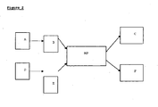
- the first sensor and the second sensor can be incorporated in a treatment device as shown diagrammatically in Figure 1 .
- the sensors “L” and “US” are associated with a plurality of elements such as, for example, a power generator “G” for powering the treatment means, a displacement controller “C” for displacing the head, an ultrasound scanner “S” connected to the probe, a display screen “D”, and a computer “PC” to manage the device. All of the elements of the device including sensors “L” and “US” are connected to the "PC”.
- the elements "US", “G”, “C”, “PC” "D” and others are described in detail in related applications WO 2006/129047 and WO 2006/129045 .
- the first sensor may be a non contact distance measuring toot “L”, such as for example a laser. This is depicted on the left side of the Figure 1 .
- the way the tool "L” detects motion may be as follows: “L” emits a laser beam which is directed towards the throat of the patient. In other embodiments, the first sensor is placed directly on the patient's larynx.
- the light reflected by the patient skin is focused by a lens onto a linear detector (the light follows the dashed lines as shown in Figure 1 ). Depending on the position of the focused light on the linear detector, the distance to the skin is calculated.
- “L” can be a commercial device, such as Model OADM 20I4471/S14C from Baumer Electric.
- the OADM laser distance sensor may be a self-contained unit designed to accurately measure the distance to a target based on triangulation and output the measurement either through an analog and/or a digital interface.
- the sensors preferably incorporate microprocessor technology to further optimize the dual analog output.
- the OADM 20 laser distance sensors may utilize a fast microcontroller that enables flexible adaptation of different parameters to the user's requirements.
- Laser light is available in either a laser beam or a laser beam line configuration depending on the target's surface. These sensors may be equipped with a 90° connector for quick and easy adaptability to the application environment:
- the first sensor may be a strain gauge and/or may be or include an electromyography sensor.
- the second sensor is mostly used to track the motion of the tissues, such as for example thyroid and/or parathyroid with ultrasound imaging.
- the imaging means may be an ultrasonic imaging probe, in another embodiment, the imaging means may be an X-ray probe, and in yet another embodiment, the imaging means may be a Magnetic Resonance Imaging (MRI) device.
- the second sensor is an ultrasonic scanning probe.
- the imaging means achieve representation of the tissue motion in space or in a plane. It is advantageous that the ultrasound array is disposed sagittally to the patient, i.e. parallel to the neck.
- the preferred imaging means is the ultrasonic probe designated by "US". This element of the therapeutic device is shown in Figure 1 and is described in detail in the related applications WO 2006/129045 and WO 2006/129047 .
- the synchronizing electronics may be embedded in a computer "PC" shown in Figure 1 .
- the synchronizing electronics may combine the signals from the swallowing sensor with HIFU pulse triggering, such that if swallowing is detected, no pulse is triggered; and/or the applicator of HIFU energy is directed to follow the appropriate tissue when the patient moves.
- Methods for administering HIFU therapy to treat disorders of thyroid and parathyroid tissue include treatment of the benign and malignant thyroid and parathyroid disorders such as for example thyroid nodules, hyperthyroidism, primary and secondary hyperparathyroidism, thyroid and parathyroid cancer and others.
- the treatment of the thyroid and parathyroid tissue with HIFU devices takes 10 to 30 minutes in an outpatient clinic.
- a local anesthetic is administered prior to treatment.
- the ultrasound energy may be gradually increased until more than 70% of the targeted thyroid or parathyroid tissue is destroyed.
- the tumor may be treated in several sessions, with sufficient time between each session for the macrophages in the patient's body to clear away the necrotic tissue resulting from the previous treatment session, thus effectively debriding the treatment side and exposing remaining tumor tissue for the next HIFU therapy session.
- Several HIFU therapy sessions may be needed to completely eradicate the tumor.
- HIFU thyrotropin
- LT4 suppressive levothyroxine
- standard chemotherapy drugs may yield synergistic results, particularly by beginning the HIFU therapy after the maximum benefit of the drug therapy on the tumor and/or nodule has been realized.
- the subject receiving the treatment when performing the treatment according to the instant method, periodically swallows (A). Accordingly, the first sensor placed directly on the larynx may be used to detect such movement (e.g., swallowing) of the subject (B) and then may transmit a signal to the microprocessor (MP) regarding such detected motion. The microprocessor may then signal for the HIFU generator to stop generating pulses during the period of the motion, thereby preventing injury to the subject receiving treatment (C). Concurrently, the subject receiving treatment periodically moves the neck region of the subject undergoing treatment (D).
- the first sensor placed directly on the larynx may be used to detect such movement (e.g., swallowing) of the subject (B) and then may transmit a signal to the microprocessor (MP) regarding such detected motion. The microprocessor may then signal for the HIFU generator to stop generating pulses during the period of the motion, thereby preventing injury to the subject receiving treatment (C).
- the subject receiving treatment periodically moves the neck region of the subject undergoing treatment (D).
- the second sensor may be used to detect such movement of the subject with the use of imaging means, from a first position to a second position (E), and then transmits a signal regarding this movement to the microprocessor (MP).
- the microprocessor may then signal the controller (e.g., a microprocessor) of the HIFU generator to reposition the generator to keep the HIFU pulses focused on the thyroid and/or parathyroid of the subject in the second position (F).
- the controller e.g., a microprocessor
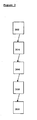
- the flow chart shown in Figure 3 is a diagram outlining various steps of the method for treating disorders of thyroid and/or parathyroid with HIFU in a subject.
- the first sensor is positioned to detect at least one of a neck motion, a throat motion and a swallowing motion. In some cases, the first sensor is placed directly on the larynx.
- the second sensor is positioned to detect position of a thyroid and/or parathyroid in the subject. In some cases, the second sensor is positioned directly on thyroid and/or parathyroid tissue.
- the HIFU pulse generator is provided to generate at least one HIFU pulse to the subject.
- the controlling means for controlling the HIFU pulse generator are provided.
- synchronizing means for synchronizing a signal from at least one of the first sensor and the second sensor with the HIFU pulse generator are provided. Finally at 310 the controlling HIFU generator ceases the HIFU pulses when the first sensor detects motion.
- the synchronizing means may comprise a microprocessor and/or other electronic circuits or software run on the microprocessor (e.g. computer), and may be combined with a microprocessor/computer which comprises the controlling means.
- the MP unit controls and, in some embodiments also synchronizes, a signal from at least one of the first sensor and the second senor with the HIFU pulse generator.
- first sensor detects at least one of neck motion, throat motion and swallowing motion, it sends a signal to the MP which processes information and in turn sends a signal to HIFU generator to cease HIFU pulses.
- second sensor detects the change in position of the thyroid and parathyroid from first position to a second position, it sends a signal to the MP which processes information and in turn sends a signal to the HIFU pulse generator to adjust accordingly, such that for example at least one HIFU pulse is focused on the parathyroid or thyroid in the second position.
- the procedure begins by placing the first sensor to the neck area to detect at least one motion of the neck, throat and/or a swallowing motion. If any motion is detected by the first sensor, the signal is sent to the MP unit which processes the received information, and further sends the signal to the HIFU generator to cease HIFU pulse. If the first sensor does not detect any motion in the neck area, the signal is sent to the MP unit which processes information and further sends the signal to the HIFU generator to continue generating at least one pulse.
- the signal is sent to the MP which processes the information and further sends the signal to the HIFU generator to cease pulse until the position is adjusted, such that the HIFU generator is focused on the thyroid or parathyroid tissue.
- the signal is sent to the MP which further sends the signal to the HIFU generator to continue generating at least one pulse.
- the signal received from the first sensor and the second sensor is sent to the MP and is further synchronized with the HIFU pulse generator.
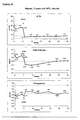
- Figures 5a and 5b are examples of time dependent courses of blood levels after HIFU treatments for two different patients. Dashed lines show the boundaries of the target values for the respective levels.
- Figure 5a relates to a 71 years old woman with primary hyperparathyroidism in the left side.
- the figure shows the time dependent course of the parathyroid hormone blood level in pmol/l
- the time dependent course of the calcium level in mmol/l in a second plotting the time dependent course of the calcium level in mmol/l
- a third plotting the time dependent course of the phosporus level in mmol/l is presented.
- Figure 5b is an analogue presentation of second patient, a 73 years old woman with primary hyperparathyroidism in the left sidle.
- Fig. 6 and 7 schematically show the geometry of a visualization and treatment unit VTU and a schematic arrangement of the VTU on the skin of a patient.
- the VTU includes an ultrasound treatment transducer, a linear imaging array, sensors and electronics (not shown in detail).
- the transducer for generating ultrasound has a concave shape with a certain radius of curvature in order to focus ultrasound.
- the radius of curvature and thus the focal point is selected so as to reach a treatment area including the parathyroid.
Description
- The present invention is generally directed to devices for synchronizing High Intensity Focused Ultrasound (HIFU) pulse delivery with movements of a patient undergoing treatment directed to thyroid and parathyroid tissue. Such movements include swallowing.
- The use of ultrasound, including high intensity focused ultrasound (HIFU) for therapeutic purposes has received significant attention in the medical community. During treatment, a portion of the mechanical energy from these high intensity sound waves is converted at the targeted location into thermal energy. The amount of thermal energy converted can be sufficiently intense to cauterize tissue, or to cause tissue necrosis (by inducing a temperature rise to beyond 70° C). Importantly, the focal point of this energy deposition can be tightly controlled so as to obtain tissue necrosis in a small target area without damaging adjoining tissue. Thus, both benign and malignant tumors can be destroyed with HIFU without surgical exposure to the tumor site.
- A particular advantage of HIFU therapy over certain traditional therapies is that HIFU is less invasive. Further advantages include reduced blood loss, reduced risk of infection, shorter hospital stays, and lower health care costs. HIFU has the potential to provide an additional treatment methodology consistent with this trend by offering a method of non-invasive surgery. For example, HIFU enables transcutaneous tumor treatment without making a single incision, thus avoiding blood loss and the risk of infection and with few side effects. Furthermore, HIFU therapy may be performed without the need for general anesthesia, thereby reducing surgical complications and cost. Most importantly, these treatments may be performed on an outpatient basis, further reducing health care cost, while increasing patient comfort.
- The application of HIFU for the destruction of benign and malignant tumors in the neck area presents a relatively new direction in the field. Patients with thyroid and parathyroid tumors benefit significantly from relatively non-invasive nature of HIFU. Further, among benign conditions of the neck area, thyroid nodules are frequently discovered during routine physical examination or during investigations for other purposes. Recently, systematic ultrasonographic exploration of a French large adult cohort indicated that 14.5% of subjects had nodular thyroid structures (Valeix et al. (2001), Ann Endocrinol (Paris) 62(6):499-506.) In the United States, 40% of the female population aged 50 or older feature thyroid nodules at ultrasonography, and the prevalence of thyroid nodules increases throughout life. Patients having such benign nodules are subject to long follow-up procedures, and the best therapeutic strategy after the discovery of such nodules is still a matter of debate. Often, the goal of the physician becomes avoiding surgery and choosing among minimally invasive treatments which may be done in ambulatory settings and result in fewer side effects compared to surgery.
- HIFU is a promising non-invasive procedure for treatment of the disorders of the neck tissue. However, enduring problems of HIFU application remain in accurately assessing, targeting and monitoring ablated tissues during the therapeutic treatment. Specifically, application of HIFU to the wrong tissue in the neck of a patient can lead to a lower treatment efficacy and to various side effects, such as for example loss of voice, due to damaging the laryngeal nerves. Thus, in an attempt to circumvent the deficiencies in the art, devices were developed to attempt synchronization of HIFU energy with the movements of patients.
-
US 5720286 teaches a method of applying focused ultrasound to the thyroid of a patient. The method includes monitoring the movement of the patient during the focused ultrasound treatment, particularly at the trachea. Echo location is used to determine the position of a portion of the patient's body to identify a treatment zone. If a change in position is detected, an alarm signal is triggered and the position of the therapy device is changed. Thereby, the therapy on the thyroid is continued as the focused ultrasound is kept targeted on the thyroid. -
US572086 fails to disclose, teach or suggest movements in relation to swallowing, nor is it understood to disclose, teach or suggest a separate sensor for the detection of movement of the larynx. Moreover,US5720286 also fails to disclose, teach or suggest the stoppage of a signal from the focused ultrasound therapy device in response to swallowing. -
U.S. Patent No. 6,076,005 discloses gating of therapeutic energy including sonic energy based on the respiratory cycle of the patient. The patient's lungs are monitored to provide quasi-continuous measurements of the actions of the patient's lungs. However,U.S. Patent No. 6,076,005 fails to disclose, teach or suggest movements in relation to swallowing, nor does it teach a separate sensor for the detection of movement of the larynx. Further,U.S. 6,076,005 also fails to disclose, teach or suggest the stoppage of a signal from the focused ultrasound therapy device in response to swallowing. - Thus, there is a general need in the art to provide HIFU devices capable to deliver therapeutic energy to the correct tissue i.e. the thyroid or parathyroid, despite the movement of the tissue of the neck due to patient's swallowing or other movement during treatment.
- The invention is defined in the appended claims. Methods disclosed herein do not form part of the invention. The foregoing and other features, aspects, and advantages of the present invention will be more apparent from the following detailed description, which illustrates exemplary embodiments of the present invention.
- The features and advantages of the invention will be set forth in the description which follows, and in part will be apparent from the description, or may be learned by the practice of the invention without undue experimentation. The features and advantages of the invention may be realized and obtained by means of the instruments and combinations particularly pointed out in the drawings, subsequent detailed description and appended claims. The invention provides an ultrasound therapeutic treatment device comprising a first sensor for detecting a swallowing motion in a subject; a second sensor for detecting a thyroid and/or parathyroid in the subject, a high intensity focused ultrasound (HIFU) pulse generator and controlling means for controlling the HIFU pulse generator based on signals from at least one of the first sensor and the second sensor.
- In some embodiments, the treatment device may comprise a controlling means for controlling various aspects of the method and/or system/device, such means may include a micro processor or the equivalent thereof. In some embodiments, when the first sensor detects movement of a patient, the controlling means stops pulse generation from the HIFU pulse generator. Preferably, the first sensor is positioned on the larynx of the patient. In some embodiments, when the second sensor detects a change in position of a tissue in the patient from a first position to a second position, the controlling means adjusts the HIFU generator such that at least one HIFU pulse is focused on the tissue in the second position. Preferably, the tissue is parathyroid and/or thyroid tissue. Optionally the second sensor is an ultrasonic scanning probe.
- The first sensor is selected from the group consisting of a strain gauge, a laser to measure distance, an electromyography sensor, an MRI sensor, a scintigraphy sensor, a scan or pet-scan sensor, an X-ray sensor and a combination of any of the foregoing.
- A method for treating disorders of thyroid and/or parathyroid with HIFU in a subject in need thereof is provided and may comprise the steps of positioning a first sensor to detect at least one of neck motion, throat motion and swallowing motion in the subject; positioning a second sensor to detect a position of a thyroid and/or parathyroid in the subject; positioning a HIFU pulse generator to provide at least one HIFU pulse to the subject; and controlling the HIFU pulse generator to cease HIFU pulses upon the first sensor detecting motion. Preferably, the second sensor is positioned sagitally i.e. parallel to the neck of the patient.
- The method may further comprise the step of providing at least one of controlling means for controlling the HIFU pulse generator and synchronizing means for synchronizing a signal from at least one of the first sensor and the second sensor with the HIFU pulse generator.
- The aforementioned method may further comprise the step of detecting a change in position of the parathyroid and/or thyroid from a first position to a second position and adjusting the HIFU generator such that at least one HIFU pulse is focused on the parathyroid and/or thyroid in the second position.
- The method may further comprise the step of selecting the first sensor from the group consisting of a strain gauge, a laser to measure distance, an electromyography sensor, an MRI sensor, a scintigraphy sensor, a scan or pet-scan sensor, an X-ray sensor and a combination of any of the foregoing.
- The method relates to the disorders of the thyroid and parathyroid selected form the group consisting of thyroid nodules, hyperthyroidism, primary or secondary hyperparathyroidism, thyroid cancer, parathyroid cancer and any combination of the foregoing.
- The system according to the invention comprises a first sensor for detecting at least one of neck motion, throat motion and swallowing motion in a subject; a second sensor for detecting a thyroid and/or parathyroid in the subject; a high intensity focused ultrasound pulse (HIFU) generator; a micro processor for controlling the HIFU pulse generator based on signals from at least one of the first sensor and the second sensor. According to this embodiment, when the first sensor detects a swallowing motion, the controlling means stops pulse generation from the HIFU pulse generator.
- The second sensor may be used to detect a change in position of the parathyroid and/or thyroid from a first position to a second position. In such embodiments, the control-ling means adjusts the HIFU generator such that a HIFU pulse is focused on the parathyroid and/or thyroid in the second position.
- A method for treating disorders of thyroid and/or parathyroid with HIFU in a subject is provided and may include the steps of positioning a first sensor to detect at least one of neck motion, throat motion and swallowing motion in the subject; positioning a second sensor to detect a position of a thyroid and/or parathyroid in the subject; providing a HIFU pulse generator to provide at least one HIFU pulse to the subject. Furthermore, at least one of controlling means for controlling the HIFU pulse generator and synchronizing means for synchronizing a signal from at least one of the first sensor and the second sensor with the HIFU pulse generator are provided which in turn control the HIFU pulse generator to cease HIFU pulses upon the first sensor detecting a swallowing motion.
- The method may relate to detecting a change in position of the parathyroid and/or thyroid from a first position to a second position and adjusting the HIFU generator such that at least one HIFU pulse is focused on the parathyroid and/or thyroid in the second position.
- Moreover, the method may relate to disorders of the thyroid and parathyroid selected form the group consisting of thyroid nodules, hyperthyroidism, primary or secondary hyperparathyroidism, thyroid cancer, parathyroid cancer and any combination of the foregoing.
- Methods disclosed herein may be used to treat and/or alleviate the symptoms of thyroid nodules, hyperthyroidism, primary or secondary hyperparathyroidism, thyroid cancer or parathyroid cancer and other known thyroid and parathyroid disorders.
- Parathyroid glands are four pea-sized glands located just behind the thyroid gland in the front of the neck. Hyperparathyroidism is an overactivity of one of the four parathyroid glands resulting in excess production of parathyroid hormone (PTH), also called parathyroid hormone. The parathyroid hormone regulates calcium and phosphate levels and helps to maintain these levels. Overactivity of one or more of the parathyroid glands causes high calcium levels (hypercalcemia) and low levels of phosphate in the blood. Primary hyperparathyroidism, also called Parathyroid-related hypercalcemia, results from a hyperfunction of the parathyroid glands themselves. There is oversecretion of PTH due to adenoma, hyperplasia or, rarely, carcinoma of the parathyroid glands. About 90 percent of all cases of hyperparathyroidism are caused by an adenoma. The tumors seldom are cancerous. They will grow to a much larger size than the parathyroid glands, often to the size of a walnut. Genetic disorders or multiple endocrine tumors also can cause a parathyroid gland to enlarge and oversecrete hormone. In 10 percent or fewer of patients with primary hyperparathyroidism, there is enlargement of all four parathyroid glands. Usually, only one of the four parathyroid glands is affected. Secondary hyperparathyroidism is the reaction of the parathyroid glands to a hypocalcemia caused by something other than a parathyroid pathology, e.g. chronic renal failure.
- So far symptomatic patients usually are sent for surgery to remove the parathyroid tumor (parathyroid adenoma). Most experts believe that almost all patients with hyperparathyroidism should be evaluated for surgery.
- Diagnosis of hyperparathyroidism most often is made when a blood test (radioimmunoassay) reveals high levels of parathyroid hormone and calcium and low or variable phosphorous levels. A blood test that specifically measures the amount of parathyroid hormone has made diagnosis simpler.
- Methods disclosed herein may be used to treat primary or secondary hyperparathyroidism, comprising the steps of identifying a treatment zone to which ultrasonic energy should be applied and directing high intensity focused ultrasound energy towards the treatment zone.
- During the treatment, either one or more of the parathyroid glands can be treated.
- High Intensity Focused Ultrasound (HIFU) is a process that allows the delivery of a large amount of heat energy to a confined space. For example, the width of focus (6dB) at 3 MHz could be 0.84 x 0.42 x 1.5 mm (cross x cross x along axis). Thus, applying High Intensity Focused Ultrasound (HIFU) is especially appropriate for small structures such as parathyroid glands. This holds even more since parathyroids are located very close to sensitive structures, such as the trachea and the recurrent laryngeal nerve.
- Parathyroids are usually located deeper from the skin than for example the thyroid. Typically they are located in a tissue depth of 15-35 mm. However most parathyroids can be reached with the focus being arranged in a distance of for example 24.5 mm from the rim of the treatment unit.
- The treatment area may be located precisely with an external ultrasound applicator. Ultrasound imaging provides high resolution imaging of parathyroid and is better in that respect than MRI or Scanner. Parathyroids are usually hypoechoic and located behind the thyroid. Alternatively, isotope scans or fine needle aspiration can be used to confirm parathyroid status. Sensitive structures (trachea, vessels) are also visible by ultrasound.
- The image array, for example a 7.5 MHz - 12 MHz 128 element imaging linear array, is located in the centre of the treatment transducer, thus allowing constant, real-time imaging of the tissue being treated. The treatment unit may have an external diameter of 60 mm, an active diameter of 56 mm, and a width of inactive area of 14.5 mm.
- The fixed position of the array with respect to the firing transducer ensures that the acoustic energy is delivered in a precise, predictable position. The ultrasound images accurately image the tissue to be treated. The energy deposition of the device hence directly corresponds to the areas identified on those ultrasound images.
- Preferably the combined visualization and treatment unit (VTU) is rotatable on its axis and thus is able to display two planes of imaging, providing the operator with a 3D representation of the target and its surroundings.
- In a preferable embodiment of the invention, a representation of the acoustic HIFU cone is overlaid on the ultrasonic image, thus indicating the exact position of the focus. During treatment, the tissue under treatment is preferably continuously monitored by ultrasound.
- Furthermore, the ultrasonic image of the tissue taken during the targeting phase may be displayed for reference. The outlines of the target, skin, carotid and trachea are overlaid over the actual image by the operator. These two features allow the operator to continuously verify that position of the visualization and treatment unit is correct. Should there be an offset, the operator can easily reposition the visualization and treatment unit to the correct position.
- The HIFU energy is adjusted to each individual patient using an algorithm whereby starting from a low level, the VTU being in a fixed position pointing to the centre of the parathyroid, the pulse energy is gradually increased until hyperechoic marks appear on the ultrasonic real time image.
- During treatment, especially during treatment ofhyperparathyroidism, the patient advantageously lies on a treatment couch in supine position, the neck in hyperextension to facilitate access to the target. This position should be kept during the estimated duration of the procedure, about 30 minutes.
- The operator covers the patient skin with a thin layer of an ultrasonic gel over the treatment area. The operator places the VTU so that the center of the target, especially the enlarged parathyroid gland, is approximately centered laterally, and moves the VTU up or down to place marks indicating the focus on the image of the target. By rotating the VTU on itself, the centering is performed both transversally and longitudinally.
- The focal point is centered on the outlined target.
- The pulse acoustic energy applied to the treatment area is the product of acoustic power by the duration of the pulse. The acoustic power is the electric power to the transducer time the electro-acoustic efficiency of the transducer. In practice the maximum acoustic power is 70 W.
- The reference power being the acoustic power that reaches the focus when the VTU is in water is for example set at 15.3 W by default. The reference pulse duration is set at 6 s by default. The reference pulse energy is thus 92 J.
- The first pulse is delivered to the tissue using the reference energy corrected for depth. The emitted power P is corrected as a function of a target depth to take into account a part of the ultrasonic absorption of the tissue superficial to the focal zone, according to the formula:

Where: - Pref : reference power in Watts; for example 15.3 Watt by default but adjustable by the operator;
- The term exp() takes into account some of the acoustic power lost by the beam in the superficial tissues before reaching the focus;
- F: Ultrasound frequency expressed in MHz (fixed value set to 3 MHz);
- D: Target depth, i.e. distance between the skin to the focal point, expressed in cm;
- µ: Tissue acoustical absorption expressed in Neper/cm/MHz. The exact value is unknown as it depends on the tissue type of each individual. A low value of 0.07 Neper/cm/MHz was chosen to minimize risk of over-exposing the target.
- For example if the depth is 20 mm, which is a typical distance of a parathyroid to the skin, the total acoustic energy of the pulse will be of: 6 s x 35.45 W = 213 J. And at the lesion depth, the residual energy that has not been absorbed by the tissues is of 92 joules. For safety reasons, the reference pulse energy is limited to 281 J/pulse.
- Depending on the acoustic intensity of the transducer, there are two phenomena leading to tissue destruction, respectively to an ablation of parathyroid, with HIFU. At intermediate intensities greater than 500 Watt/cm2 and less than 3000 Watt/cm2, HIFU energy may produce cavitation bubbles near the focus. This, in turn, enhances the absorption of the tissue medium and helps transforming the incident ultrasonic energy into heat. This phenomenon is also responsible for the position of the lesion ahead of the focal point (i.e. towards the transducer). In the focal zone, the temperature rises, because the acoustic waves produce heat by acoustic absorption of the tissue. Each pulse creates a small "lesion" of coagulation. The tissue may reach boiling temperature.The heat builds up at the focus where the energy is concentrated. Where the energy is not concentrated (i.e. before and after focus), the temperature is regulated by blood flow and there is no residual effect on tissue.
- HIFU treatment, especially the treatment of parathyroidism, consists of repeated pulses, placed adjacent to one another in order to cover the whole target. The number of pulses varies between 5 and several hundred. The motion pattern is for example an outward spiral from centre. The spacing between the lesions in the motion pattern is for example 1.2 mm. The pause between two pulses must be long enough so as to let the skin cool before the next pulse is emitted.
- As some heat is deposited in the tissue located before the focal point ("pre-focal heating"), the tissue, especially the skin tissue, should be kept at normal temperature. Therefore, cooling may be provided by the VTU. In operation, the VTU is preferably covered by a thin balloon made of silicon material, effectively creating a liquid-filled chamber in front of the transducer. The fluid is for example water with 10 grams Polyvinylpyrrolidone (PVP) per 1 litre and methylene blue, which helps the operator to check that the cooling circuit is properly filled. The fluid may be originally stored in a pouch inserted in the cooler located in the Electronics Cabinet. Preferably, the fluid is circulated in a closed circuit between the pouch and the VTU by the pumps. Two temperature sensors located in the VTU ensure that the fluid in the VTU is properly cooled to 10°C and a pressure sensor, also located in the VTU, ensures that the pressure of the balloon is constant over the patient skin.
- To reduce prefocal heating or skin burn, pauses between the HIFU pulses preferably are chosen such as to allow for that tissue to return to normal temperature. In the treatment of the parathyroid gland, pauses between the pulses are instrumental in eliminating the risk of skin burns. Accordingly, the pulse repetition is limited by the capacity of the skin to withstand repetitive high acoustic power pulses. It has been determined experimentally that the average intensity should not exceed 2.5 W/cm2 at 3 MHz.
- The pauses toff can be determined according to the following formula:

Where: - ton = pulse duration in seconds;
- F: acoustic frequency in MHz;
- Acoustic power= 3 MHz acoustic power that is delivered by the transducer during the HIFU pulse. Value expressed in Watts.
- TissueDepth: Thickness of tissues to go through, from the skin to the focal point over the lesion to be treated. Value expressed in mm.
- FocustoRim: This is the distance from the focal point to the border of the active surface of the transducer projected over the ultrasound axis. This value is expressed in mm.
- TxdArea: This is the cross section area of the transducer projection on the skin. This value is expressed in cm2.
- SkinTol: This is the allowable average acoustic intensity through the skin. This value is expressed in WxMHz/cm2. The value has been determined experimentally (see above) to 2.5 W/cm2 at 3 MHz. If the acoustic frequency is 1 MHz, then Iskin should not exceed 7.5 W/cm2.
- The treatment can be performed again if necessary. Preferably, treatment is repeated at least twice, at least one week apart, focussed either at the same tissue site or at tissue sites separated by 1 mm to 1 cm from the previously treated treatment zone.
- Preferably, the method of treating hyperparathyroidism further comprises the step of measuring the blood levels of parathyroid hormone and/or calcium and/or phosphorus. By monitoring the values of at least one blood level, the effect of the treatment may be controlled.
- Additionally or alternatively, the blood levels of TSH, T3 and/or T4 hormones may be monitored.
- Preferably, a repeat course of treatment is applied depending on values of the blood level and/or on the course of the blood levels of parathyroid hormone and/or calcium and or phosphorus. For example, no further treatment is necessary if a certain blood level decreases or increases beyond a predetermined value or if a certain blood level decreases or increases by more than a predetermined amount or percentage after a predetermined time interval.
- Methods disclosed herein may be used for ablating a parathyroid, comprising the steps of identifying a treatment zone to which ultrasonic energy should be applied, said treatment zone including at least a part of the parathyroid, and directing high intensity focused ultrasound energy towards the treatment zone.
- The steps of identifying and applying energy to the treatment zone may further include: a) identifying the feeding vessel bundle of the parathyroid, for example using Doppler ultrasonography, b) applying ultrasonic energy to only the part of the parathyroid where the vessel bundle is attached to the parathyroid, that part representing for example 1/3 of the gland volume, and c) verifying that the blood flow in the bundle has been interrupted, for example using Doppler Ultrasonography.
- The ultrasound therapeutic device is provided which comprises a sensor for detecting a parathyroid in the subject and a high intensity focused ultrasound (HIFU) pulse generator, wherein said high intensity focused ultrasound (HIFU) pulse generator is operable such that it provides a focal zone being located in a treatment zone including at least a part of the parathyroid. The device may comprise means for controlling the treatment zone. The device for controlling may be a separate device or may comprise the sensor for detecting the parathyroid.
- The device for controlling the treatment zone may for example be a device for Doppler Ultrasonography to identify feeding vessels and/or to verify that blood flow has been interrupted after the treatment.
- Other objectives and advantages of the present invention will become obvious to the reader, and it is intended that these objectives and advantages are within the scope of the present invention.
- To accomplish the above and related objectives, this invention may be carried out in the form illustrated in the accompanying drawings. The drawings are illustrative only, changes may be made in the specific construction illustrated.
- For a better understanding of the present invention, reference is made to the following description, taken in conjunction with the accompanying drawings, in which like reference characters refer to like parts throughout the specification, and in which:
-
Figure 1 is an overall diagrammatic view of a complete treatment device that is suitable for incorporating the first and the second sensors of the invention according to some embodiments. -
Figure 2 andFigure 3 are flow charts showing various steps of a method for treating disorders of thyroid and/or parathyroid with HIFU in a subject. -
Figure 4 is a flow chart illustrating steps (for some methods of the present disclosure) followed during use of some apparatus/system embodiments disclosed herein. -
Figures 5a and5b are examples of time dependent courses of blood levels after HIFU treatments. -
Figure 6 and7 schematically show a visualization and treatment unit (VTU) according to the present invention. - It is noted that in this disclosure and particularly in the claims and/or paragraphs, terms such as "comprises," "comprised," "comprising," and the like can have the meaning attributed to it in U.S. patent law; that is, they can mean "includes," "included," "including," and the like, and allow for elements not explicitly recited. These and other embodiments are disclosed or are apparent from and encompassed by the following description.
- The terms "HIFU pulse generator," as used herein and in the claims that follow all refer to a HIFU transducer that is capable of being energized to produce ultrasonic waves that are much more energetic than the ultrasonic pulses produced by an imaging transducer, and which can be focused or directed onto a discrete location, such as a treatment site in a target area.
- The term "HIFU treatment" as used herein refers to a treatment comprising (i) identifying a treatment zone to which ultrasonic energy should be applied, said treatment zone including at least a part of the parathyroid, and (ii) directing high intensity focused ultrasound energy towards said treatment zone, wherein a HIFU pulse generator provides at least one HIFU pulse to the subject.
- It is to be understood that the invention is not limited in its application to the details of construction and to the arrangements of the components set forth in the following description or illustrated in the drawings. The invention is capable of other embodiments and of being practiced and carried out in various ways, where particular configurations, process steps, and materials disclosed herein may vary. In addition, it is to be understood that the phraseology and terminology employed herein are for the purpose of the description and should not be regarded as limiting. Furthermore, as will be apparent to those skilled in the art, the present invention may be embodied in other specific forms without departing from the essential characteristics thereof.
- For purposes of the description of the drawings and the embodiments of the present invention, as mentioned for the drawing,
Figure 1 may not be drawn to scale. Some areas drawn may be larger and/or simpler in order to clearly portray the improvement to what has already been established. It will nevertheless be understood that no limitation of the scope of the invention is thereby intended. Any alterations and further modifications of the inventive features illustrated herein, and any additional applications of the principles of the invention as illustrated herein, which would normally occur to one skilled in the relevant art and having possession of this disclosure, are to be considered within the scope of the invention claimed. It is also to be understood that the terminology employed herein is used for the purpose of describing particular embodiments only and is not intended to be limiting since the scope of the present invention will be limited only by the appended claims. - Referring now in detail to the drawing, the first sensor and the second sensor according to some embodiments of the present invention can be incorporated in a treatment device as shown diagrammatically in
Figure 1 . According to this device, the sensors "L" and "US" are associated with a plurality of elements such as, for example, a power generator "G" for powering the treatment means, a displacement controller "C" for displacing the head, an ultrasound scanner "S" connected to the probe, a display screen "D", and a computer "PC" to manage the device. All of the elements of the device including sensors "L" and "US" are connected to the "PC". The elements "US", "G", "C", "PC" "D" and others are described in detail in related applicationsWO 2006/129047 andWO 2006/129045 . - The first sensor may be a non contact distance measuring toot "L", such as for example a laser. This is depicted on the left side of the
Figure 1 . The way the tool "L" detects motion may be as follows: "L" emits a laser beam which is directed towards the throat of the patient. In other embodiments, the first sensor is placed directly on the patient's larynx. - The light reflected by the patient skin is focused by a lens onto a linear detector (the light follows the dashed lines as shown in
Figure 1 ). Depending on the position of the focused light on the linear detector, the distance to the skin is calculated. "L" can be a commercial device, such as Model OADM 20I4471/S14C from Baumer Electric. - The OADM laser distance sensor may be a self-contained unit designed to accurately measure the distance to a target based on triangulation and output the measurement either through an analog and/or a digital interface. The sensors preferably incorporate microprocessor technology to further optimize the dual analog output. The
OADM 20 laser distance sensors may utilize a fast microcontroller that enables flexible adaptation of different parameters to the user's requirements. Laser light is available in either a laser beam or a laser beam line configuration depending on the target's surface. These sensors may be equipped with a 90° connector for quick and easy adaptability to the application environment: - In some embodiments, the first sensor may be a strain gauge and/or may be or include an electromyography sensor.
- The second sensor is mostly used to track the motion of the tissues, such as for example thyroid and/or parathyroid with ultrasound imaging. In one embodiment, the imaging means may be an ultrasonic imaging probe, in another embodiment, the imaging means may be an X-ray probe, and in yet another embodiment, the imaging means may be a Magnetic Resonance Imaging (MRI) device. In another embodiment, the second sensor is an ultrasonic scanning probe. The imaging means achieve representation of the tissue motion in space or in a plane. It is advantageous that the ultrasound array is disposed sagittally to the patient, i.e. parallel to the neck.
- The preferred imaging means is the ultrasonic probe designated by "US". This element of the therapeutic device is shown in
Figure 1 and is described in detail in the related applicationsWO 2006/129045 andWO 2006/129047 . - In some embodiments, the synchronizing electronics may be embedded in a computer "PC" shown in
Figure 1 . The synchronizing electronics may combine the signals from the swallowing sensor with HIFU pulse triggering, such that if swallowing is detected, no pulse is triggered; and/or the applicator of HIFU energy is directed to follow the appropriate tissue when the patient moves. - Methods for administering HIFU therapy to treat disorders of thyroid and parathyroid tissue include treatment of the benign and malignant thyroid and parathyroid disorders such as for example thyroid nodules, hyperthyroidism, primary and secondary hyperparathyroidism, thyroid and parathyroid cancer and others.
- In general, the treatment of the thyroid and parathyroid tissue with HIFU devices takes 10 to 30 minutes in an outpatient clinic. A local anesthetic is administered prior to treatment. The ultrasound energy may be gradually increased until more than 70% of the targeted thyroid or parathyroid tissue is destroyed.
- It has been observed that a complete thyroid and/or parathyroid tumor treatment (100% shrinkage) may be obtained. Alternatively, the tumor may be treated in several sessions, with sufficient time between each session for the macrophages in the patient's body to clear away the necrotic tissue resulting from the previous treatment session, thus effectively debriding the treatment side and exposing remaining tumor tissue for the next HIFU therapy session. Several HIFU therapy sessions may be needed to completely eradicate the tumor. Further, the treatment of a benign and/or malignant tumor using a combination of HIFU and drugs, such as for example thyrotropin (TSH) suppressive levothyroxine (LT4) and/or standard chemotherapy drugs, may yield synergistic results, particularly by beginning the HIFU therapy after the maximum benefit of the drug therapy on the tumor and/or nodule has been realized.
- As shown in
Figure 2 , when performing the treatment according to the instant method, the subject receiving the treatment periodically swallows (A). Accordingly, the first sensor placed directly on the larynx may be used to detect such movement (e.g., swallowing) of the subject (B) and then may transmit a signal to the microprocessor (MP) regarding such detected motion. The microprocessor may then signal for the HIFU generator to stop generating pulses during the period of the motion, thereby preventing injury to the subject receiving treatment (C). Concurrently, the subject receiving treatment periodically moves the neck region of the subject undergoing treatment (D). Accordingly, in some embodiments, the second sensor may be used to detect such movement of the subject with the use of imaging means, from a first position to a second position (E), and then transmits a signal regarding this movement to the microprocessor (MP). The microprocessor may then signal the controller (e.g., a microprocessor) of the HIFU generator to reposition the generator to keep the HIFU pulses focused on the thyroid and/or parathyroid of the subject in the second position (F). - The flow chart shown in
Figure 3 is a diagram outlining various steps of the method for treating disorders of thyroid and/or parathyroid with HIFU in a subject. Starting at 302, the first sensor is positioned to detect at least one of a neck motion, a throat motion and a swallowing motion. In some cases, the first sensor is placed directly on the larynx. Then at 304 the second sensor is positioned to detect position of a thyroid and/or parathyroid in the subject. In some cases, the second sensor is positioned directly on thyroid and/or parathyroid tissue. At 306, the HIFU pulse generator is provided to generate at least one HIFU pulse to the subject. At 308, the controlling means for controlling the HIFU pulse generator are provided. In some embodiments, in addition to controlling means, synchronizing means for synchronizing a signal from at least one of the first sensor and the second sensor with the HIFU pulse generator are provided. Finally at 310 the controlling HIFU generator ceases the HIFU pulses when the first sensor detects motion. The synchronizing means may comprise a microprocessor and/or other electronic circuits or software run on the microprocessor (e.g. computer), and may be combined with a microprocessor/computer which comprises the controlling means. - The MP unit controls and, in some embodiments also synchronizes, a signal from at least one of the first sensor and the second senor with the HIFU pulse generator. Specifically, when first sensor detects at least one of neck motion, throat motion and swallowing motion, it sends a signal to the MP which processes information and in turn sends a signal to HIFU generator to cease HIFU pulses. Similarly, when the second sensor detects the change in position of the thyroid and parathyroid from first position to a second position, it sends a signal to the MP which processes information and in turn sends a signal to the HIFU pulse generator to adjust accordingly, such that for example at least one HIFU pulse is focused on the parathyroid or thyroid in the second position. Some embodiments of this kind are also summarized in
Figure 4 . Specifically, the procedure begins by placing the first sensor to the neck area to detect at least one motion of the neck, throat and/or a swallowing motion. If any motion is detected by the first sensor, the signal is sent to the MP unit which processes the received information, and further sends the signal to the HIFU generator to cease HIFU pulse. If the first sensor does not detect any motion in the neck area, the signal is sent to the MP unit which processes information and further sends the signal to the HIFU generator to continue generating at least one pulse. - Similarly, if the second sensor detects a change in the position of the thyroid or parathyroid tissue, the signal is sent to the MP which processes the information and further sends the signal to the HIFU generator to cease pulse until the position is adjusted, such that the HIFU generator is focused on the thyroid or parathyroid tissue. However, if the second sensor does not detect position of the thyroid or parathyroid, the signal is sent to the MP which further sends the signal to the HIFU generator to continue generating at least one pulse. In some embodiments, the signal received from the first sensor and the second sensor is sent to the MP and is further synchronized with the HIFU pulse generator.
-
Figures 5a and5b are examples of time dependent courses of blood levels after HIFU treatments for two different patients. Dashed lines show the boundaries of the target values for the respective levels. -
Figure 5a relates to a 71 years old woman with primary hyperparathyroidism in the left side. In a first plotting, the figure shows the time dependent course of the parathyroid hormone blood level in pmol/l, in a second plotting the time dependent course of the calcium level in mmol/l, and in a third plotting the time dependent course of the phosporus level in mmol/l is presented. -
Figure 5b is an analogue presentation of second patient, a 73 years old woman with primary hyperparathyroidism in the left sidle. - The plotting starts after a first HIFU treatment. In both examples, parathyroid hormone and calcium levels do not significantly drop after the first treatment. For the second patient, the parathyroid hormone level even rises during the first four weeks after the first treatment. In both cases, the HIFU treatment is repeated after 5 weeks.
- After the second HIFU treatment the blood level of parathyroid hormone and the blood level of calcium significantly decrease, respectively, that is by more than 30 % with respect to the originally measured value. The long-term behaviour confirms the success of the treatment. Even after 30 weeks after the first treatment (25 weeks after the second HIFU treatment) the blood levels rest on a stable level. A further treatment is thus not necessary.
- The third plottings of
Figures 5a and5b show the time dependent course of the phosphorus level. The phosphorus levels slightly increase after the second treatment, which can give an additional hint to the success of the therapy. -
Fig. 6 and7 schematically show the geometry of a visualization and treatment unit VTU and a schematic arrangement of the VTU on the skin of a patient. The VTU includes an ultrasound treatment transducer, a linear imaging array, sensors and electronics (not shown in detail). - As shown in
Fig. 7 , the transducer for generating ultrasound has a concave shape with a certain radius of curvature in order to focus ultrasound. The radius of curvature and thus the focal point is selected so as to reach a treatment area including the parathyroid. - Typically and by way of example, the geometrical parameters of the VTU are chosen as follows:
Radius of curvature of transducer 38 mm Distance from rim 24.5 mm Width of focus (6dB) @ 3 MHz, cross x cross x along axis 0.84 x 0.42 x 1.5 mm Active Diameter 56 mm Width of Inactive area 14.5 mm External diameter at end of VTU 60 mm Acoustic frequency 3 MHz Maximum acoustic power 70 W - For parathyroids that are located deeper below the skin, it is possible to use a power transducer with a longer radius of curvature. For example, if the transducer is built with a radius of curvature of 45 mm instead of 38 mm, the distance from the rim becomes 35 mm, and the focal zone is located at a distance such that parathyroids as deep as 35 mm can be treated.
- While illustrative embodiments of the invention have been described above, it is, of course, understood that various modifications will be apparent to those of ordinary skill in the art.
- Although illustrative embodiments of the invention have been described in detail herein with reference to the accompanying drawings, it is to be understood that the invention is not limited to those precise embodiments, and that various changes and modifications can be effected therein by one skilled in the art.
Claims (11)
- An ultrasound therapeutic device for therapeutic treatment of thyroid and/or parathyroid tissue, comprising:a first sensor (L) for detecting at least a swallowing motion of the larynx in a subject, the first sensor (L) being selected from the group consisting of: a strain gauge, a laser to measure distance, an electromyography sensor, an MRI sensor, a scintigraphy sensor, a scan or pet-scan sensor, an X-ray sensor and a combination of any of the foregoing;a second sensor (US) for detecting a thyroid tissue and/or parathyroid tissue in the subject;a high intensity focused ultrasound - HIFU - pulse generator;controlling means for controlling the HIFU pulse generator based on signals from at least one of the first sensor (L) and the second sensor (US),wherein the controlling means is configured to stop pulse generation from the HIFU pulse generator when the first sensor (L) detects a swallowing motion.
- The treatment device according to claim 1, wherein the controlling means comprises a micro processor (MP).
- The treatment device according to any of claims 1 or 2, wherein, when the second sensor (US) detects a change in position of a parathyroid and/or thyroid tissue from a first position to a second position, the controlling means is configured to adjust the HIFU generator such that at least one HIFU pulse is focused on the parathyroid and/or thyroid tissue in the second position.
- The ultrasound therapeutic device according to any of claims 1 to 3,
wherein said high intensity focused ultrasound pulse generator is operable to provide a focal zone in a treatment zone including at least a part of the parathyroid. - The ultrasound therapeutic treatment device according to any of claims 1 to 4, comprising means for identifying vessels and/or controlling the blood flow in a vessel in the treatment zone.
- The ultrasound therapeutic treatment device according to claim 5, wherein means for identifying vessels and/or controlling the blood flow comprises a device for Doppler Ultrasonography.
- The ultrasound therapeutic treatment device according to claim 4,
comprising a treatment unit configured to deliver HIFU pulses to tissue, and configured to locate said focal zone in a distance from the rim of the treatment unit so as to reach target depths up to 35 mm. - The ultrasound therapeutic treatment device according to claim 4,
comprising a treatment unit configured to deliver HIFU pulses to tissue, and configured to locate said focal zone in a distance from the rim of the treatment unit so as to reach target depths up to 24.5 mm. - The ultrasound therapeutic treatment device according to claim 7 or 8,
wherein said treatment unit is provided as a combined visualization and treatment head including a HIFU transducer operably connected to said HIFU pulse generator, and furthermore incorporating said second sensor (US) comprising an imaging array. - The ultrasound therapeutic treatment device according to claim 9,
wherein the imaging array is located in the centre of the HIFU transducer. - The ultrasound therapeutic treatment device according to claim 9 or 10,
wherein the imaging array is an ultrasound imaging array.
Applications Claiming Priority (3)
| Application Number | Priority Date | Filing Date | Title |
|---|---|---|---|
| US12/251,175 US9757595B2 (en) | 2008-10-14 | 2008-10-14 | Systems and methods for synchronizing ultrasound treatment of thryoid and parathyroid with movements of patients |
| US12/364,916 US8353832B2 (en) | 2008-10-14 | 2009-02-03 | Systems and methods for ultrasound treatment of thyroid and parathyroid |
| PCT/EP2009/063353 WO2010043621A1 (en) | 2008-10-14 | 2009-10-13 | Systems and methods for ultrasound treatment of thyroid and parathyroid |
Publications (3)
| Publication Number | Publication Date |
|---|---|
| EP2364184A1 EP2364184A1 (en) | 2011-09-14 |
| EP2364184B1 true EP2364184B1 (en) | 2014-04-16 |
| EP2364184B8 EP2364184B8 (en) | 2014-06-11 |
Family
ID=41490291
Family Applications (1)
| Application Number | Title | Priority Date | Filing Date |
|---|---|---|---|
| EP09736912.8A Active EP2364184B8 (en) | 2008-10-14 | 2009-10-13 | System for hifu treatment of thyroid and parathyroid |
Country Status (5)
| Country | Link |
|---|---|
| US (1) | US8353832B2 (en) |
| EP (1) | EP2364184B8 (en) |
| JP (1) | JP5535225B2 (en) |
| CN (1) | CN102405077B (en) |
| WO (1) | WO2010043621A1 (en) |
Families Citing this family (15)
| Publication number | Priority date | Publication date | Assignee | Title |
|---|---|---|---|---|
| JP5873009B2 (en) * | 2010-04-07 | 2016-03-01 | 株式会社日本触媒 | Poly (meth) acrylic acid polymer aqueous solution and method for producing the same |
| US8876740B2 (en) | 2010-04-12 | 2014-11-04 | University Of Washington | Methods and systems for non-invasive treatment of tissue using high intensity focused ultrasound therapy |
| CN103180015A (en) * | 2010-10-26 | 2013-06-26 | 皇家飞利浦电子股份有限公司 | Therapeutic apparatus, computer-implemented method, and computer program product for controlling the focus of radiation into a moving target zone |
| EP2665520B1 (en) * | 2011-01-18 | 2018-11-21 | Koninklijke Philips N.V. | Therapeutic apparatus, computer program product, and method for determining an achievable target region for high intensity focused ultrasound |
| KR101644011B1 (en) * | 2011-02-01 | 2016-08-01 | 주식회사 하이로닉 | High Intensity Focused Ultrasonic Medical Instrument with Dual Transducers |
| CA2830652A1 (en) * | 2011-03-30 | 2012-10-04 | The Gillette Company | Method of viewing a surface |
| EP2886159A1 (en) * | 2013-12-23 | 2015-06-24 | Theraclion SA | Method for operating a device for treatment of a tissue and device for treatment of a tissue |
| WO2015148966A1 (en) * | 2014-03-28 | 2015-10-01 | Khokhlova Vera | Boiling histotripsy methods and systems for uniform volumetric ablation of an object by high-intensity focused ultrasound waves with shocks |
| EP3355795B1 (en) * | 2015-09-29 | 2019-07-31 | Institut National de la Sante et de la Recherche Medicale (INSERM) | Device and system for generating ultrasonic waves in a target region of a soft solid and method for locally treating a tissue |
| CN108831532B (en) * | 2018-06-15 | 2022-03-29 | 北京大学第一医院 | Method and system for processing nuclear medicine thyroid gland imaging image |
| CN109394261A (en) * | 2018-09-11 | 2019-03-01 | 云南省第人民医院 | A kind of throat check device and method based on B ultrasound imaging |
| EP3986319A1 (en) * | 2019-06-19 | 2022-04-27 | Theraclion SA | Method, device, and method for using of a device to coagulate varicose veins with high-intensity focused ultrasound |
| CN111166387B (en) * | 2020-01-22 | 2022-09-30 | 无锡祥生医疗科技股份有限公司 | Method and device for ultrasonic imaging of thyroid |
| CN111568382B (en) * | 2020-05-21 | 2023-04-07 | 中国计量科学研究院 | Intelligent measurement system for intra-thyroid irradiation iodine measurement |
| CN113133826B (en) * | 2021-04-23 | 2023-04-07 | 四川大学华西医院 | HIFU low-temperature focusing method, equipment and system |
Citations (2)
| Publication number | Priority date | Publication date | Assignee | Title |
|---|---|---|---|---|
| US6097984A (en) * | 1998-11-25 | 2000-08-01 | Medtronic, Inc. | System and method of stimulation for treating gastro-esophageal reflux disease |
| US7585296B2 (en) * | 1998-02-19 | 2009-09-08 | Mederi Therapeutics, Inc. | Method to treat gastric reflux via the detection and ablation of gastro-esophageal nerves and receptors |
Family Cites Families (44)
| Publication number | Priority date | Publication date | Assignee | Title |
|---|---|---|---|---|
| US4370983A (en) * | 1971-01-20 | 1983-02-01 | Lichtenstein Eric Stefan | Computer-control medical care system |
| US6405072B1 (en) * | 1991-01-28 | 2002-06-11 | Sherwood Services Ag | Apparatus and method for determining a location of an anatomical target with reference to a medical apparatus |
| DE4241161C2 (en) * | 1992-12-07 | 1995-04-13 | Siemens Ag | Acoustic therapy facility |
| FR2720260B1 (en) * | 1994-05-30 | 1996-09-27 | Technomed Medical Systems | Use of a mode A ultrasound system for monitoring the position of a patient during a therapy session, and method and apparatus comprising same. |
| EP0734742B1 (en) * | 1995-03-31 | 2005-05-11 | Kabushiki Kaisha Toshiba | Ultrasound therapeutic apparatus |
| JPH1028742A (en) * | 1996-07-18 | 1998-02-03 | Hitachi Medical Corp | Radioactive therapeutic apparatus |
| DE19732125C1 (en) * | 1997-07-25 | 1999-02-11 | Tomtec Imaging Syst Gmbh | Method for taking ultrasound images of moving objects |
| US6076005A (en) * | 1998-02-25 | 2000-06-13 | St. Jude Children's Research Hospital | Respiration responsive gating means and apparatus and methods using the same |
| US6066123A (en) * | 1998-04-09 | 2000-05-23 | The Board Of Trustees Of The Leland Stanford Junior University | Enhancement of bioavailability by use of focused energy delivery to a target tissue |
| US6501981B1 (en) * | 1999-03-16 | 2002-12-31 | Accuray, Inc. | Apparatus and method for compensating for respiratory and patient motions during treatment |
| US6488626B1 (en) * | 1999-04-07 | 2002-12-03 | Riverside Research Institute | Ultrasonic sensing by induced tissue motion |
| US6626855B1 (en) * | 1999-11-26 | 2003-09-30 | Therus Corpoation | Controlled high efficiency lesion formation using high intensity ultrasound |
| EP1110507A3 (en) * | 1999-12-21 | 2001-10-31 | EchoTech GmbH | Method and system for generating three dimensional ultrasound image data sets |
| US6484053B2 (en) * | 2000-11-29 | 2002-11-19 | Pairash Thajchayapong | Method and apparatus for treating poor laryngeal-elevation disorder with sequential-high voltage electrical stimulation |
| US6517492B2 (en) * | 2001-02-22 | 2003-02-11 | Texon Technologies Ltd. | Method and apparatus for assessment of cardiac function by monitoring movement of the trachea |
| US20020193685A1 (en) * | 2001-06-08 | 2002-12-19 | Calypso Medical, Inc. | Guided Radiation Therapy System |
| FR2827149B1 (en) * | 2001-07-13 | 2003-10-10 | Technomed Medical Systems | FOCUSED ULTRASOUND TREATMENT PROBE |
| WO2003068047A2 (en) * | 2002-02-11 | 2003-08-21 | Gold - T Tech, Inc. | Method for preventing thrombus formation |
| US20050027333A1 (en) * | 2002-08-30 | 2005-02-03 | Lennox Arlene J. | Methods and systems for monitoring range of motion for a patient's head and neck area |
| CA2454144C (en) * | 2002-12-27 | 2008-12-16 | Uri Agam | Device and method for adaptive ultrasound sensing |
| JP2006519048A (en) * | 2003-02-28 | 2006-08-24 | コーニンクレッカ フィリップス エレクトロニクス エヌ ヴィ | Method and apparatus for improving motion tracking for HIFU ultrasound therapy |
| US7171257B2 (en) * | 2003-06-11 | 2007-01-30 | Accuray Incorporated | Apparatus and method for radiosurgery |
| JP2007516810A (en) * | 2003-12-30 | 2007-06-28 | ライポソニックス, インコーポレイテッド | Ultrasonic therapy head with motion control |
| EP1713395B1 (en) * | 2004-01-13 | 2018-08-29 | Robarts Research Institute | An ultrasound imaging system and corresponding methods |
| US20080269607A1 (en) * | 2004-06-11 | 2008-10-30 | Kazunari Ishida | Ultrasonic Treatment Apparatus |
| US8095203B2 (en) * | 2004-07-23 | 2012-01-10 | Varian Medical Systems, Inc. | Data processing for real-time tracking of a target in radiation therapy |
| EP1778086A4 (en) * | 2004-07-23 | 2009-03-18 | Calypso Med Technologies Inc | Systems and methods for real time tracking of targets in radiation therapy and other medical applications |
| JP4727253B2 (en) * | 2004-08-05 | 2011-07-20 | サッポロビール株式会社 | Continuous swallowing motion measuring device and continuous swallowing motion measuring method |
| US20060241443A1 (en) * | 2004-11-22 | 2006-10-26 | Whitmore Willet F Iii | Real time ultrasound monitoring of the motion of internal structures during respiration for control of therapy delivery |
| JP4750429B2 (en) * | 2005-02-08 | 2011-08-17 | 株式会社日立メディコ | Image display device |
| US7837634B2 (en) * | 2005-03-03 | 2010-11-23 | Proteus Biomedical, Inc. | Fiberoptic tissue motion sensor |
| CN101166474B (en) * | 2005-03-04 | 2012-07-04 | 视声公司 | Method for synchronization of breathing signal with the capture of ultrasound data |
| EP1866409B1 (en) * | 2005-04-06 | 2011-10-12 | Duke University | Parathyroid and thymus transplantation in digeorge syndrome subjects |
| CA2807044C (en) * | 2005-05-03 | 2014-06-10 | The University Of Western Ontario | An oral device and kit for use in association therewith |
| US20090221902A1 (en) * | 2005-06-02 | 2009-09-03 | Cancercure Technology As | Ultrasound Treatment Center |
| FR2886551B1 (en) | 2005-06-03 | 2007-09-07 | Theraclion Soc Par Actions Sim | METHOD FOR DETERMINING DISTANCE AND PROCESSING APPARATUS USING THE SAME |
| FR2886534A1 (en) | 2005-06-03 | 2006-12-08 | Theraclion Soc Par Actions Sim | IMAGING AND PROCESSING HEAD OF LIVING ORGANS AND METHOD OF MANUFACTURING |
| WO2007005976A1 (en) * | 2005-07-01 | 2007-01-11 | Hansen Medical, Inc. | Robotic catheter system |
| US7621873B2 (en) * | 2005-08-17 | 2009-11-24 | University Of Washington | Method and system to synchronize acoustic therapy with ultrasound imaging |
| US8079957B2 (en) * | 2005-11-18 | 2011-12-20 | Siemens Medical Solutions Usa, Inc. | Synchronized three or four-dimensional medical ultrasound imaging and measurements |
| US20070161894A1 (en) * | 2005-12-23 | 2007-07-12 | Mark Zdeblick | Ultrasound synchrony measurement |
| US20070276244A1 (en) * | 2006-05-02 | 2007-11-29 | Siemens Medical Solutions Usa, Inc. | Responsive medical diagnostic ultrasound imaging system and method |
| US7612763B2 (en) * | 2006-08-03 | 2009-11-03 | Schneider Data Technologies | Computer peripheral with integrated infrared therapy and method of making same |
| US8251908B2 (en) * | 2007-10-01 | 2012-08-28 | Insightec Ltd. | Motion compensated image-guided focused ultrasound therapy system |
-
2009
- 2009-02-03 US US12/364,916 patent/US8353832B2/en active Active
- 2009-10-13 JP JP2011531472A patent/JP5535225B2/en active Active
- 2009-10-13 CN CN200980150127.9A patent/CN102405077B/en active Active
- 2009-10-13 EP EP09736912.8A patent/EP2364184B8/en active Active
- 2009-10-13 WO PCT/EP2009/063353 patent/WO2010043621A1/en active Application Filing
Patent Citations (2)
| Publication number | Priority date | Publication date | Assignee | Title |
|---|---|---|---|---|
| US7585296B2 (en) * | 1998-02-19 | 2009-09-08 | Mederi Therapeutics, Inc. | Method to treat gastric reflux via the detection and ablation of gastro-esophageal nerves and receptors |
| US6097984A (en) * | 1998-11-25 | 2000-08-01 | Medtronic, Inc. | System and method of stimulation for treating gastro-esophageal reflux disease |
Also Published As
| Publication number | Publication date |
|---|---|
| CN102405077B (en) | 2015-11-25 |
| EP2364184A1 (en) | 2011-09-14 |
| JP5535225B2 (en) | 2014-07-02 |
| CN102405077A (en) | 2012-04-04 |
| EP2364184B8 (en) | 2014-06-11 |
| US8353832B2 (en) | 2013-01-15 |
| WO2010043621A1 (en) | 2010-04-22 |
| US20100094178A1 (en) | 2010-04-15 |
| JP2012509691A (en) | 2012-04-26 |
Similar Documents
| Publication | Publication Date | Title |
|---|---|---|
| EP2364184B1 (en) | System for hifu treatment of thyroid and parathyroid | |
| US9802063B2 (en) | Reflective ultrasound technology for dermatological treatments | |
| US9364164B2 (en) | Non-invasive device and method for locating a structure such as a nerve | |
| US6685639B1 (en) | High intensity focused ultrasound system for scanning and curing tumor | |
| US9955946B2 (en) | Carotid body ablation with a transvenous ultrasound imaging and ablation catheter | |
| US8206299B2 (en) | Image guided high intensity focused ultrasound treatment of nerves | |
| CN103025381B (en) | By office's system of HIFU Treatment hysteromyoma or other tissue | |
| US7722539B2 (en) | Treatment of unwanted tissue by the selective destruction of vasculature providing nutrients to the tissue | |
| US8197409B2 (en) | Ultrasound guided high intensity focused ultrasound treatment of nerves | |
| EP2731675B1 (en) | Systems and methods for coupling an ultrasound source to tissue | |
| EP2600783A2 (en) | Systems and methods for ultrasound treatment | |
| KR101562998B1 (en) | Fat Melting Medical Device for Obesity Improvement by using Electronic RF and highly concentrated Ultrasound | |
| KR102428353B1 (en) | High intensity focused ultrasound operating apparatus and operating method thereof | |
| JPH0747079A (en) | Ultrasonic therapeutic system | |
| EP3030167A2 (en) | Carotid body ablation via directed energy | |
| JP7303834B2 (en) | Systems, devices and methods for treatment of nasal disorders | |
| US9757595B2 (en) | Systems and methods for synchronizing ultrasound treatment of thryoid and parathyroid with movements of patients | |
| KR102244287B1 (en) | Operating apparatus for sensing nerve and generating energy | |
| Chen et al. | Clinical external ultrasonic treatment devices | |
| Li et al. | Lili Chen |
Legal Events
| Date | Code | Title | Description |
|---|---|---|---|
| PUAI | Public reference made under article 153(3) epc to a published international application that has entered the european phase |
Free format text: ORIGINAL CODE: 0009012 |
|
| 17P | Request for examination filed |
Effective date: 20110413 |
|
| AK | Designated contracting states |
Kind code of ref document: A1 Designated state(s): AT BE BG CH CY CZ DE DK EE ES FI FR GB GR HR HU IE IS IT LI LT LU LV MC MK MT NL NO PL PT RO SE SI SK SM TR |
|
| DAX | Request for extension of the european patent (deleted) | ||
| 17Q | First examination report despatched |
Effective date: 20121106 |
|
| GRAP | Despatch of communication of intention to grant a patent |
Free format text: ORIGINAL CODE: EPIDOSNIGR1 |
|
| INTG | Intention to grant announced |
Effective date: 20130902 |
|
| GRAP | Despatch of communication of intention to grant a patent |
Free format text: ORIGINAL CODE: EPIDOSNIGR1 |
|
| INTG | Intention to grant announced |
Effective date: 20131206 |
|
| GRAS | Grant fee paid |
Free format text: ORIGINAL CODE: EPIDOSNIGR3 |
|
| GRAA | (expected) grant |
Free format text: ORIGINAL CODE: 0009210 |
|
| AK | Designated contracting states |
Kind code of ref document: B1 Designated state(s): AT BE BG CH CY CZ DE DK EE ES FI FR GB GR HR HU IE IS IT LI LT LU LV MC MK MT NL NO PL PT RO SE SI SK SM TR |
|
| REG | Reference to a national code |
Ref country code: GB Ref legal event code: FG4D |
|
| REG | Reference to a national code |
Ref country code: CH Ref legal event code: EP |
|
| REG | Reference to a national code |
Ref country code: AT Ref legal event code: REF Ref document number: 662138 Country of ref document: AT Kind code of ref document: T Effective date: 20140515 |
|
| RAP2 | Party data changed (patent owner data changed or rights of a patent transferred) |
Owner name: THERACLION SA |
|
| REG | Reference to a national code |
Ref country code: IE Ref legal event code: FG4D Ref country code: DE Ref legal event code: R082 Ref document number: 602009023291 Country of ref document: DE Representative=s name: PATENTANWALTSKANZLEI MEYER, DE |
|
| REG | Reference to a national code |
Ref country code: DE Ref legal event code: R096 Ref document number: 602009023291 Country of ref document: DE Effective date: 20140528 |
|
| REG | Reference to a national code |
Ref country code: CH Ref legal event code: NV Representative=s name: MEYER AND KOLLEGEN, CH |
|
| REG | Reference to a national code |
Ref country code: AT Ref legal event code: MK05 Ref document number: 662138 Country of ref document: AT Kind code of ref document: T Effective date: 20140416 |
|
| REG | Reference to a national code |
Ref country code: NL Ref legal event code: VDEP Effective date: 20140416 |
|
| REG | Reference to a national code |
Ref country code: LT Ref legal event code: MG4D |
|
| PG25 | Lapsed in a contracting state [announced via postgrant information from national office to epo] |
Ref country code: FI Free format text: LAPSE BECAUSE OF FAILURE TO SUBMIT A TRANSLATION OF THE DESCRIPTION OR TO PAY THE FEE WITHIN THE PRESCRIBED TIME-LIMIT Effective date: 20140416 Ref country code: NL Free format text: LAPSE BECAUSE OF FAILURE TO SUBMIT A TRANSLATION OF THE DESCRIPTION OR TO PAY THE FEE WITHIN THE PRESCRIBED TIME-LIMIT Effective date: 20140416 Ref country code: GR Free format text: LAPSE BECAUSE OF FAILURE TO SUBMIT A TRANSLATION OF THE DESCRIPTION OR TO PAY THE FEE WITHIN THE PRESCRIBED TIME-LIMIT Effective date: 20140717 Ref country code: CY Free format text: LAPSE BECAUSE OF FAILURE TO SUBMIT A TRANSLATION OF THE DESCRIPTION OR TO PAY THE FEE WITHIN THE PRESCRIBED TIME-LIMIT Effective date: 20140416 Ref country code: IS Free format text: LAPSE BECAUSE OF FAILURE TO SUBMIT A TRANSLATION OF THE DESCRIPTION OR TO PAY THE FEE WITHIN THE PRESCRIBED TIME-LIMIT Effective date: 20140816 Ref country code: LT Free format text: LAPSE BECAUSE OF FAILURE TO SUBMIT A TRANSLATION OF THE DESCRIPTION OR TO PAY THE FEE WITHIN THE PRESCRIBED TIME-LIMIT Effective date: 20140416 Ref country code: NO Free format text: LAPSE BECAUSE OF FAILURE TO SUBMIT A TRANSLATION OF THE DESCRIPTION OR TO PAY THE FEE WITHIN THE PRESCRIBED TIME-LIMIT Effective date: 20140716 Ref country code: BG Free format text: LAPSE BECAUSE OF FAILURE TO SUBMIT A TRANSLATION OF THE DESCRIPTION OR TO PAY THE FEE WITHIN THE PRESCRIBED TIME-LIMIT Effective date: 20140716 |
|
| PG25 | Lapsed in a contracting state [announced via postgrant information from national office to epo] |
Ref country code: AT Free format text: LAPSE BECAUSE OF FAILURE TO SUBMIT A TRANSLATION OF THE DESCRIPTION OR TO PAY THE FEE WITHIN THE PRESCRIBED TIME-LIMIT Effective date: 20140416 Ref country code: PL Free format text: LAPSE BECAUSE OF FAILURE TO SUBMIT A TRANSLATION OF THE DESCRIPTION OR TO PAY THE FEE WITHIN THE PRESCRIBED TIME-LIMIT Effective date: 20140416 Ref country code: SE Free format text: LAPSE BECAUSE OF FAILURE TO SUBMIT A TRANSLATION OF THE DESCRIPTION OR TO PAY THE FEE WITHIN THE PRESCRIBED TIME-LIMIT Effective date: 20140416 Ref country code: ES Free format text: LAPSE BECAUSE OF FAILURE TO SUBMIT A TRANSLATION OF THE DESCRIPTION OR TO PAY THE FEE WITHIN THE PRESCRIBED TIME-LIMIT Effective date: 20140416 Ref country code: LV Free format text: LAPSE BECAUSE OF FAILURE TO SUBMIT A TRANSLATION OF THE DESCRIPTION OR TO PAY THE FEE WITHIN THE PRESCRIBED TIME-LIMIT Effective date: 20140416 Ref country code: HR Free format text: LAPSE BECAUSE OF FAILURE TO SUBMIT A TRANSLATION OF THE DESCRIPTION OR TO PAY THE FEE WITHIN THE PRESCRIBED TIME-LIMIT Effective date: 20140416 |
|
| PG25 | Lapsed in a contracting state [announced via postgrant information from national office to epo] |
Ref country code: PT Free format text: LAPSE BECAUSE OF FAILURE TO SUBMIT A TRANSLATION OF THE DESCRIPTION OR TO PAY THE FEE WITHIN THE PRESCRIBED TIME-LIMIT Effective date: 20140818 |
|
| REG | Reference to a national code |
Ref country code: DE Ref legal event code: R097 Ref document number: 602009023291 Country of ref document: DE |
|
| PG25 | Lapsed in a contracting state [announced via postgrant information from national office to epo] |
Ref country code: EE Free format text: LAPSE BECAUSE OF FAILURE TO SUBMIT A TRANSLATION OF THE DESCRIPTION OR TO PAY THE FEE WITHIN THE PRESCRIBED TIME-LIMIT Effective date: 20140416 Ref country code: DK Free format text: LAPSE BECAUSE OF FAILURE TO SUBMIT A TRANSLATION OF THE DESCRIPTION OR TO PAY THE FEE WITHIN THE PRESCRIBED TIME-LIMIT Effective date: 20140416 Ref country code: SK Free format text: LAPSE BECAUSE OF FAILURE TO SUBMIT A TRANSLATION OF THE DESCRIPTION OR TO PAY THE FEE WITHIN THE PRESCRIBED TIME-LIMIT Effective date: 20140416 Ref country code: BE Free format text: LAPSE BECAUSE OF FAILURE TO SUBMIT A TRANSLATION OF THE DESCRIPTION OR TO PAY THE FEE WITHIN THE PRESCRIBED TIME-LIMIT Effective date: 20140416 Ref country code: RO Free format text: LAPSE BECAUSE OF FAILURE TO SUBMIT A TRANSLATION OF THE DESCRIPTION OR TO PAY THE FEE WITHIN THE PRESCRIBED TIME-LIMIT Effective date: 20140416 Ref country code: CZ Free format text: LAPSE BECAUSE OF FAILURE TO SUBMIT A TRANSLATION OF THE DESCRIPTION OR TO PAY THE FEE WITHIN THE PRESCRIBED TIME-LIMIT Effective date: 20140416 |
|
| PLBE | No opposition filed within time limit |
Free format text: ORIGINAL CODE: 0009261 |
|
| STAA | Information on the status of an ep patent application or granted ep patent |
Free format text: STATUS: NO OPPOSITION FILED WITHIN TIME LIMIT |
|
| 26N | No opposition filed |
Effective date: 20150119 |
|
| REG | Reference to a national code |
Ref country code: DE Ref legal event code: R097 Ref document number: 602009023291 Country of ref document: DE Effective date: 20150119 |
|
| PG25 | Lapsed in a contracting state [announced via postgrant information from national office to epo] |
Ref country code: LU Free format text: LAPSE BECAUSE OF FAILURE TO SUBMIT A TRANSLATION OF THE DESCRIPTION OR TO PAY THE FEE WITHIN THE PRESCRIBED TIME-LIMIT Effective date: 20141013 Ref country code: MC Free format text: LAPSE BECAUSE OF FAILURE TO SUBMIT A TRANSLATION OF THE DESCRIPTION OR TO PAY THE FEE WITHIN THE PRESCRIBED TIME-LIMIT Effective date: 20140416 |
|
| REG | Reference to a national code |
Ref country code: IE Ref legal event code: MM4A |
|
| PG25 | Lapsed in a contracting state [announced via postgrant information from national office to epo] |
Ref country code: SI Free format text: LAPSE BECAUSE OF FAILURE TO SUBMIT A TRANSLATION OF THE DESCRIPTION OR TO PAY THE FEE WITHIN THE PRESCRIBED TIME-LIMIT Effective date: 20140416 |
|
| PG25 | Lapsed in a contracting state [announced via postgrant information from national office to epo] |
Ref country code: IE Free format text: LAPSE BECAUSE OF NON-PAYMENT OF DUE FEES Effective date: 20141013 |
|
| PG25 | Lapsed in a contracting state [announced via postgrant information from national office to epo] |
Ref country code: SM Free format text: LAPSE BECAUSE OF FAILURE TO SUBMIT A TRANSLATION OF THE DESCRIPTION OR TO PAY THE FEE WITHIN THE PRESCRIBED TIME-LIMIT Effective date: 20140416 |
|
| PG25 | Lapsed in a contracting state [announced via postgrant information from national office to epo] |
Ref country code: MT Free format text: LAPSE BECAUSE OF FAILURE TO SUBMIT A TRANSLATION OF THE DESCRIPTION OR TO PAY THE FEE WITHIN THE PRESCRIBED TIME-LIMIT Effective date: 20140416 Ref country code: HU Free format text: LAPSE BECAUSE OF FAILURE TO SUBMIT A TRANSLATION OF THE DESCRIPTION OR TO PAY THE FEE WITHIN THE PRESCRIBED TIME-LIMIT; INVALID AB INITIO Effective date: 20091013 Ref country code: TR Free format text: LAPSE BECAUSE OF FAILURE TO SUBMIT A TRANSLATION OF THE DESCRIPTION OR TO PAY THE FEE WITHIN THE PRESCRIBED TIME-LIMIT Effective date: 20140416 |
|
| REG | Reference to a national code |
Ref country code: FR Ref legal event code: PLFP Year of fee payment: 8 |
|
| REG | Reference to a national code |
Ref country code: FR Ref legal event code: PLFP Year of fee payment: 9 |
|
| PG25 | Lapsed in a contracting state [announced via postgrant information from national office to epo] |
Ref country code: MK Free format text: LAPSE BECAUSE OF FAILURE TO SUBMIT A TRANSLATION OF THE DESCRIPTION OR TO PAY THE FEE WITHIN THE PRESCRIBED TIME-LIMIT Effective date: 20140416 |
|
| REG | Reference to a national code |
Ref country code: FR Ref legal event code: PLFP Year of fee payment: 10 |
|
| PGFP | Annual fee paid to national office [announced via postgrant information from national office to epo] |
Ref country code: IT Payment date: 20230920 Year of fee payment: 15 Ref country code: GB Payment date: 20230920 Year of fee payment: 15 |
|
| PGFP | Annual fee paid to national office [announced via postgrant information from national office to epo] |
Ref country code: FR Payment date: 20230920 Year of fee payment: 15 |
|
| PGFP | Annual fee paid to national office [announced via postgrant information from national office to epo] |
Ref country code: DE Payment date: 20230920 Year of fee payment: 15 Ref country code: CH Payment date: 20231102 Year of fee payment: 15 |