EP2366412A2 - Catheter device - Google Patents
Catheter device Download PDFInfo
- Publication number
- EP2366412A2 EP2366412A2 EP10008269A EP10008269A EP2366412A2 EP 2366412 A2 EP2366412 A2 EP 2366412A2 EP 10008269 A EP10008269 A EP 10008269A EP 10008269 A EP10008269 A EP 10008269A EP 2366412 A2 EP2366412 A2 EP 2366412A2
- Authority
- EP
- European Patent Office
- Prior art keywords
- distal
- catheter device
- drive shaft
- proximal
- pump
- Prior art date
- Legal status (The legal status is an assumption and is not a legal conclusion. Google has not performed a legal analysis and makes no representation as to the accuracy of the status listed.)
- Granted
Links
- 230000008878 coupling Effects 0.000 claims description 94
- 238000010168 coupling process Methods 0.000 claims description 94
- 238000005859 coupling reaction Methods 0.000 claims description 94
- 238000011010 flushing procedure Methods 0.000 claims description 13
- 239000004814 polyurethane Substances 0.000 abstract description 19
- 238000000034 method Methods 0.000 abstract description 9
- 229920002635 polyurethane Polymers 0.000 abstract description 3
- 210000004369 blood Anatomy 0.000 description 24
- 239000008280 blood Substances 0.000 description 24
- 238000005086 pumping Methods 0.000 description 18
- 210000002216 heart Anatomy 0.000 description 17
- 239000010432 diamond Substances 0.000 description 13
- 125000006850 spacer group Chemical group 0.000 description 13
- 239000000463 material Substances 0.000 description 11
- 210000005240 left ventricle Anatomy 0.000 description 10
- 230000033001 locomotion Effects 0.000 description 10
- 239000004698 Polyethylene Substances 0.000 description 8
- 210000000709 aorta Anatomy 0.000 description 8
- 239000000306 component Substances 0.000 description 8
- 229920000573 polyethylene Polymers 0.000 description 8
- 239000004743 Polypropylene Substances 0.000 description 7
- 229920001155 polypropylene Polymers 0.000 description 7
- 238000013461 design Methods 0.000 description 6
- 238000005553 drilling Methods 0.000 description 6
- 239000000243 solution Substances 0.000 description 6
- 229920002614 Polyether block amide Polymers 0.000 description 5
- FAPWRFPIFSIZLT-UHFFFAOYSA-M Sodium chloride Chemical compound [Na+].[Cl-] FAPWRFPIFSIZLT-UHFFFAOYSA-M 0.000 description 5
- 239000004809 Teflon Substances 0.000 description 5
- 229920006362 Teflon® Polymers 0.000 description 5
- 210000001765 aortic valve Anatomy 0.000 description 5
- 210000004204 blood vessel Anatomy 0.000 description 5
- 229920003023 plastic Polymers 0.000 description 5
- 239000004033 plastic Substances 0.000 description 5
- 238000004804 winding Methods 0.000 description 5
- 230000008859 change Effects 0.000 description 4
- 238000001816 cooling Methods 0.000 description 4
- 229910001000 nickel titanium Inorganic materials 0.000 description 4
- HLXZNVUGXRDIFK-UHFFFAOYSA-N nickel titanium Chemical compound [Ti].[Ti].[Ti].[Ti].[Ti].[Ti].[Ti].[Ti].[Ti].[Ti].[Ti].[Ni].[Ni].[Ni].[Ni].[Ni].[Ni].[Ni].[Ni].[Ni].[Ni].[Ni].[Ni].[Ni].[Ni] HLXZNVUGXRDIFK-UHFFFAOYSA-N 0.000 description 4
- -1 polyethylene Polymers 0.000 description 4
- 239000012781 shape memory material Substances 0.000 description 4
- 239000010935 stainless steel Substances 0.000 description 4
- 229910001220 stainless steel Inorganic materials 0.000 description 4
- 238000003860 storage Methods 0.000 description 4
- 210000002376 aorta thoracic Anatomy 0.000 description 3
- 230000015572 biosynthetic process Effects 0.000 description 3
- 230000006835 compression Effects 0.000 description 3
- 238000007906 compression Methods 0.000 description 3
- 210000003709 heart valve Anatomy 0.000 description 3
- 238000002513 implantation Methods 0.000 description 3
- 230000001050 lubricating effect Effects 0.000 description 3
- 229920001343 polytetrafluoroethylene Polymers 0.000 description 3
- 239000004810 polytetrafluoroethylene Substances 0.000 description 3
- 239000004800 polyvinyl chloride Substances 0.000 description 3
- 229920000915 polyvinyl chloride Polymers 0.000 description 3
- 230000002829 reductive effect Effects 0.000 description 3
- 229910001369 Brass Inorganic materials 0.000 description 2
- 229920002307 Dextran Polymers 0.000 description 2
- WQZGKKKJIJFFOK-GASJEMHNSA-N Glucose Natural products OC[C@H]1OC(O)[C@H](O)[C@@H](O)[C@@H]1O WQZGKKKJIJFFOK-GASJEMHNSA-N 0.000 description 2
- 239000004696 Poly ether ether ketone Substances 0.000 description 2
- 229920002319 Poly(methyl acrylate) Polymers 0.000 description 2
- 239000004830 Super Glue Substances 0.000 description 2
- RTAQQCXQSZGOHL-UHFFFAOYSA-N Titanium Chemical compound [Ti] RTAQQCXQSZGOHL-UHFFFAOYSA-N 0.000 description 2
- 239000000853 adhesive Substances 0.000 description 2
- 230000001070 adhesive effect Effects 0.000 description 2
- 238000005452 bending Methods 0.000 description 2
- 239000010951 brass Substances 0.000 description 2
- 206010007625 cardiogenic shock Diseases 0.000 description 2
- 230000000295 complement effect Effects 0.000 description 2
- 210000004351 coronary vessel Anatomy 0.000 description 2
- 238000006073 displacement reaction Methods 0.000 description 2
- 239000008151 electrolyte solution Substances 0.000 description 2
- 229940021013 electrolyte solution Drugs 0.000 description 2
- FGBJXOREULPLGL-UHFFFAOYSA-N ethyl cyanoacrylate Chemical compound CCOC(=O)C(=C)C#N FGBJXOREULPLGL-UHFFFAOYSA-N 0.000 description 2
- 239000008103 glucose Substances 0.000 description 2
- 238000003801 milling Methods 0.000 description 2
- 210000004165 myocardium Anatomy 0.000 description 2
- 210000000056 organ Anatomy 0.000 description 2
- 230000002093 peripheral effect Effects 0.000 description 2
- 229920002530 polyetherether ketone Polymers 0.000 description 2
- 230000001012 protector Effects 0.000 description 2
- 238000007789 sealing Methods 0.000 description 2
- 210000002966 serum Anatomy 0.000 description 2
- 239000011780 sodium chloride Substances 0.000 description 2
- 230000006641 stabilisation Effects 0.000 description 2
- 238000011105 stabilization Methods 0.000 description 2
- 230000008719 thickening Effects 0.000 description 2
- 239000010936 titanium Substances 0.000 description 2
- 229910052719 titanium Inorganic materials 0.000 description 2
- 230000007704 transition Effects 0.000 description 2
- 230000002861 ventricular Effects 0.000 description 2
- XLYOFNOQVPJJNP-UHFFFAOYSA-N water Substances O XLYOFNOQVPJJNP-UHFFFAOYSA-N 0.000 description 2
- 238000003466 welding Methods 0.000 description 2
- 229920000049 Carbon (fiber) Polymers 0.000 description 1
- RYGMFSIKBFXOCR-UHFFFAOYSA-N Copper Chemical compound [Cu] RYGMFSIKBFXOCR-UHFFFAOYSA-N 0.000 description 1
- 229910000881 Cu alloy Inorganic materials 0.000 description 1
- 229920001651 Cyanoacrylate Polymers 0.000 description 1
- 239000004593 Epoxy Substances 0.000 description 1
- 229910000640 Fe alloy Inorganic materials 0.000 description 1
- 206010019280 Heart failures Diseases 0.000 description 1
- 208000000913 Kidney Calculi Diseases 0.000 description 1
- MWCLLHOVUTZFKS-UHFFFAOYSA-N Methyl cyanoacrylate Chemical compound COC(=O)C(=C)C#N MWCLLHOVUTZFKS-UHFFFAOYSA-N 0.000 description 1
- 206010029148 Nephrolithiasis Diseases 0.000 description 1
- BQCADISMDOOEFD-UHFFFAOYSA-N Silver Chemical compound [Ag] BQCADISMDOOEFD-UHFFFAOYSA-N 0.000 description 1
- NIXOWILDQLNWCW-UHFFFAOYSA-N acrylic acid group Chemical group C(C=C)(=O)O NIXOWILDQLNWCW-UHFFFAOYSA-N 0.000 description 1
- 230000009471 action Effects 0.000 description 1
- 230000006978 adaptation Effects 0.000 description 1
- 210000001367 artery Anatomy 0.000 description 1
- 230000004323 axial length Effects 0.000 description 1
- 230000008901 benefit Effects 0.000 description 1
- JUPQTSLXMOCDHR-UHFFFAOYSA-N benzene-1,4-diol;bis(4-fluorophenyl)methanone Chemical compound OC1=CC=C(O)C=C1.C1=CC(F)=CC=C1C(=O)C1=CC=C(F)C=C1 JUPQTSLXMOCDHR-UHFFFAOYSA-N 0.000 description 1
- WQZGKKKJIJFFOK-VFUOTHLCSA-N beta-D-glucose Chemical compound OC[C@H]1O[C@@H](O)[C@H](O)[C@@H](O)[C@@H]1O WQZGKKKJIJFFOK-VFUOTHLCSA-N 0.000 description 1
- 239000000560 biocompatible material Substances 0.000 description 1
- 230000005540 biological transmission Effects 0.000 description 1
- 230000000903 blocking effect Effects 0.000 description 1
- 230000017531 blood circulation Effects 0.000 description 1
- 239000012503 blood component Substances 0.000 description 1
- 210000000988 bone and bone Anatomy 0.000 description 1
- 239000004917 carbon fiber Substances 0.000 description 1
- 230000000747 cardiac effect Effects 0.000 description 1
- 210000000748 cardiovascular system Anatomy 0.000 description 1
- 239000000919 ceramic Substances 0.000 description 1
- 230000004087 circulation Effects 0.000 description 1
- 230000001112 coagulating effect Effects 0.000 description 1
- 239000002131 composite material Substances 0.000 description 1
- 150000001875 compounds Chemical class 0.000 description 1
- 238000010276 construction Methods 0.000 description 1
- 229910052802 copper Inorganic materials 0.000 description 1
- 239000010949 copper Substances 0.000 description 1
- 238000013016 damping Methods 0.000 description 1
- 230000007547 defect Effects 0.000 description 1
- 238000011161 development Methods 0.000 description 1
- 230000018109 developmental process Effects 0.000 description 1
- 229910003460 diamond Inorganic materials 0.000 description 1
- 230000000694 effects Effects 0.000 description 1
- 239000013013 elastic material Substances 0.000 description 1
- 229920001971 elastomer Polymers 0.000 description 1
- 239000000806 elastomer Substances 0.000 description 1
- 210000001174 endocardium Anatomy 0.000 description 1
- 229920006332 epoxy adhesive Polymers 0.000 description 1
- 230000003628 erosive effect Effects 0.000 description 1
- 210000001105 femoral artery Anatomy 0.000 description 1
- 239000000835 fiber Substances 0.000 description 1
- 239000012530 fluid Substances 0.000 description 1
- 230000006870 function Effects 0.000 description 1
- 239000007789 gas Substances 0.000 description 1
- PCHJSUWPFVWCPO-UHFFFAOYSA-N gold Chemical compound [Au] PCHJSUWPFVWCPO-UHFFFAOYSA-N 0.000 description 1
- 239000010931 gold Substances 0.000 description 1
- 229910052737 gold Inorganic materials 0.000 description 1
- 210000004013 groin Anatomy 0.000 description 1
- 208000019622 heart disease Diseases 0.000 description 1
- 239000001307 helium Substances 0.000 description 1
- 229910052734 helium Inorganic materials 0.000 description 1
- SWQJXJOGLNCZEY-UHFFFAOYSA-N helium atom Chemical compound [He] SWQJXJOGLNCZEY-UHFFFAOYSA-N 0.000 description 1
- 230000000004 hemodynamic effect Effects 0.000 description 1
- 230000006872 improvement Effects 0.000 description 1
- 238000001802 infusion Methods 0.000 description 1
- 230000003993 interaction Effects 0.000 description 1
- 230000002427 irreversible effect Effects 0.000 description 1
- 230000000670 limiting effect Effects 0.000 description 1
- 239000007788 liquid Substances 0.000 description 1
- 230000007774 longterm Effects 0.000 description 1
- 238000005461 lubrication Methods 0.000 description 1
- 239000000696 magnetic material Substances 0.000 description 1
- 230000007246 mechanism Effects 0.000 description 1
- 229910052751 metal Inorganic materials 0.000 description 1
- 239000002184 metal Substances 0.000 description 1
- 239000007769 metal material Substances 0.000 description 1
- VNWKTOKETHGBQD-UHFFFAOYSA-N methane Chemical compound C VNWKTOKETHGBQD-UHFFFAOYSA-N 0.000 description 1
- TWNQGVIAIRXVLR-UHFFFAOYSA-N oxo(oxoalumanyloxy)alumane Chemical compound O=[Al]O[Al]=O TWNQGVIAIRXVLR-UHFFFAOYSA-N 0.000 description 1
- 239000003058 plasma substitute Substances 0.000 description 1
- 229920000052 poly(p-xylylene) Polymers 0.000 description 1
- 229920001296 polysiloxane Polymers 0.000 description 1
- 230000008569 process Effects 0.000 description 1
- 238000011084 recovery Methods 0.000 description 1
- 238000010992 reflux Methods 0.000 description 1
- 230000002441 reversible effect Effects 0.000 description 1
- 230000033764 rhythmic process Effects 0.000 description 1
- 210000005241 right ventricle Anatomy 0.000 description 1
- 229910001750 ruby Inorganic materials 0.000 description 1
- 239000010979 ruby Substances 0.000 description 1
- 238000000926 separation method Methods 0.000 description 1
- 229910001285 shape-memory alloy Inorganic materials 0.000 description 1
- 206010040560 shock Diseases 0.000 description 1
- 230000035939 shock Effects 0.000 description 1
- 238000004904 shortening Methods 0.000 description 1
- 229910052709 silver Inorganic materials 0.000 description 1
- 239000004332 silver Substances 0.000 description 1
- 210000003270 subclavian artery Anatomy 0.000 description 1
- 230000003319 supportive effect Effects 0.000 description 1
- 238000011477 surgical intervention Methods 0.000 description 1
- 238000001356 surgical procedure Methods 0.000 description 1
- 230000002277 temperature effect Effects 0.000 description 1
- 238000012549 training Methods 0.000 description 1
- 238000002054 transplantation Methods 0.000 description 1
- 210000003462 vein Anatomy 0.000 description 1
Images


Classifications
-
- A—HUMAN NECESSITIES
- A61—MEDICAL OR VETERINARY SCIENCE; HYGIENE
- A61M—DEVICES FOR INTRODUCING MEDIA INTO, OR ONTO, THE BODY; DEVICES FOR TRANSDUCING BODY MEDIA OR FOR TAKING MEDIA FROM THE BODY; DEVICES FOR PRODUCING OR ENDING SLEEP OR STUPOR
- A61M60/00—Blood pumps; Devices for mechanical circulatory actuation; Balloon pumps for circulatory assistance
- A61M60/40—Details relating to driving
- A61M60/403—Details relating to driving for non-positive displacement blood pumps
- A61M60/419—Details relating to driving for non-positive displacement blood pumps the force acting on the blood contacting member being permanent magnetic, e.g. from a rotating magnetic coupling between driving and driven magnets
-
- A—HUMAN NECESSITIES
- A61—MEDICAL OR VETERINARY SCIENCE; HYGIENE
- A61M—DEVICES FOR INTRODUCING MEDIA INTO, OR ONTO, THE BODY; DEVICES FOR TRANSDUCING BODY MEDIA OR FOR TAKING MEDIA FROM THE BODY; DEVICES FOR PRODUCING OR ENDING SLEEP OR STUPOR
- A61M60/00—Blood pumps; Devices for mechanical circulatory actuation; Balloon pumps for circulatory assistance
- A61M60/10—Location thereof with respect to the patient's body
- A61M60/122—Implantable pumps or pumping devices, i.e. the blood being pumped inside the patient's body
- A61M60/126—Implantable pumps or pumping devices, i.e. the blood being pumped inside the patient's body implantable via, into, inside, in line, branching on, or around a blood vessel
- A61M60/13—Implantable pumps or pumping devices, i.e. the blood being pumped inside the patient's body implantable via, into, inside, in line, branching on, or around a blood vessel by means of a catheter allowing explantation, e.g. catheter pumps temporarily introduced via the vascular system
-
- A—HUMAN NECESSITIES
- A61—MEDICAL OR VETERINARY SCIENCE; HYGIENE
- A61M—DEVICES FOR INTRODUCING MEDIA INTO, OR ONTO, THE BODY; DEVICES FOR TRANSDUCING BODY MEDIA OR FOR TAKING MEDIA FROM THE BODY; DEVICES FOR PRODUCING OR ENDING SLEEP OR STUPOR
- A61M60/00—Blood pumps; Devices for mechanical circulatory actuation; Balloon pumps for circulatory assistance
- A61M60/20—Type thereof
- A61M60/205—Non-positive displacement blood pumps
- A61M60/216—Non-positive displacement blood pumps including a rotating member acting on the blood, e.g. impeller
- A61M60/237—Non-positive displacement blood pumps including a rotating member acting on the blood, e.g. impeller the blood flow through the rotating member having mainly axial components, e.g. axial flow pumps
-
- A—HUMAN NECESSITIES
- A61—MEDICAL OR VETERINARY SCIENCE; HYGIENE
- A61M—DEVICES FOR INTRODUCING MEDIA INTO, OR ONTO, THE BODY; DEVICES FOR TRANSDUCING BODY MEDIA OR FOR TAKING MEDIA FROM THE BODY; DEVICES FOR PRODUCING OR ENDING SLEEP OR STUPOR
- A61M60/00—Blood pumps; Devices for mechanical circulatory actuation; Balloon pumps for circulatory assistance
- A61M60/80—Constructional details other than related to driving
- A61M60/802—Constructional details other than related to driving of non-positive displacement blood pumps
- A61M60/804—Impellers
- A61M60/806—Vanes or blades
- A61M60/808—Vanes or blades specially adapted for deformable impellers, e.g. expandable impellers
-
- A—HUMAN NECESSITIES
- A61—MEDICAL OR VETERINARY SCIENCE; HYGIENE
- A61M—DEVICES FOR INTRODUCING MEDIA INTO, OR ONTO, THE BODY; DEVICES FOR TRANSDUCING BODY MEDIA OR FOR TAKING MEDIA FROM THE BODY; DEVICES FOR PRODUCING OR ENDING SLEEP OR STUPOR
- A61M60/00—Blood pumps; Devices for mechanical circulatory actuation; Balloon pumps for circulatory assistance
- A61M60/80—Constructional details other than related to driving
- A61M60/802—Constructional details other than related to driving of non-positive displacement blood pumps
- A61M60/81—Pump housings
-
- A—HUMAN NECESSITIES
- A61—MEDICAL OR VETERINARY SCIENCE; HYGIENE
- A61M—DEVICES FOR INTRODUCING MEDIA INTO, OR ONTO, THE BODY; DEVICES FOR TRANSDUCING BODY MEDIA OR FOR TAKING MEDIA FROM THE BODY; DEVICES FOR PRODUCING OR ENDING SLEEP OR STUPOR
- A61M60/00—Blood pumps; Devices for mechanical circulatory actuation; Balloon pumps for circulatory assistance
- A61M60/80—Constructional details other than related to driving
- A61M60/802—Constructional details other than related to driving of non-positive displacement blood pumps
- A61M60/818—Bearings
- A61M60/825—Contact bearings, e.g. ball-and-cup or pivot bearings
-
- A—HUMAN NECESSITIES
- A61—MEDICAL OR VETERINARY SCIENCE; HYGIENE
- A61M—DEVICES FOR INTRODUCING MEDIA INTO, OR ONTO, THE BODY; DEVICES FOR TRANSDUCING BODY MEDIA OR FOR TAKING MEDIA FROM THE BODY; DEVICES FOR PRODUCING OR ENDING SLEEP OR STUPOR
- A61M60/00—Blood pumps; Devices for mechanical circulatory actuation; Balloon pumps for circulatory assistance
- A61M60/10—Location thereof with respect to the patient's body
- A61M60/122—Implantable pumps or pumping devices, i.e. the blood being pumped inside the patient's body
- A61M60/126—Implantable pumps or pumping devices, i.e. the blood being pumped inside the patient's body implantable via, into, inside, in line, branching on, or around a blood vessel
- A61M60/148—Implantable pumps or pumping devices, i.e. the blood being pumped inside the patient's body implantable via, into, inside, in line, branching on, or around a blood vessel in line with a blood vessel using resection or like techniques, e.g. permanent endovascular heart assist devices
-
- A—HUMAN NECESSITIES
- A61—MEDICAL OR VETERINARY SCIENCE; HYGIENE
- A61M—DEVICES FOR INTRODUCING MEDIA INTO, OR ONTO, THE BODY; DEVICES FOR TRANSDUCING BODY MEDIA OR FOR TAKING MEDIA FROM THE BODY; DEVICES FOR PRODUCING OR ENDING SLEEP OR STUPOR
- A61M60/00—Blood pumps; Devices for mechanical circulatory actuation; Balloon pumps for circulatory assistance
- A61M60/40—Details relating to driving
- A61M60/403—Details relating to driving for non-positive displacement blood pumps
- A61M60/408—Details relating to driving for non-positive displacement blood pumps the force acting on the blood contacting member being mechanical, e.g. transmitted by a shaft or cable
- A61M60/411—Details relating to driving for non-positive displacement blood pumps the force acting on the blood contacting member being mechanical, e.g. transmitted by a shaft or cable generated by an electromotor
- A61M60/414—Details relating to driving for non-positive displacement blood pumps the force acting on the blood contacting member being mechanical, e.g. transmitted by a shaft or cable generated by an electromotor transmitted by a rotating cable, e.g. for blood pumps mounted on a catheter
-
- A—HUMAN NECESSITIES
- A61—MEDICAL OR VETERINARY SCIENCE; HYGIENE
- A61M—DEVICES FOR INTRODUCING MEDIA INTO, OR ONTO, THE BODY; DEVICES FOR TRANSDUCING BODY MEDIA OR FOR TAKING MEDIA FROM THE BODY; DEVICES FOR PRODUCING OR ENDING SLEEP OR STUPOR
- A61M60/00—Blood pumps; Devices for mechanical circulatory actuation; Balloon pumps for circulatory assistance
- A61M60/80—Constructional details other than related to driving
- A61M60/802—Constructional details other than related to driving of non-positive displacement blood pumps
- A61M60/827—Sealings between moving parts
- A61M60/829—Sealings between moving parts having a purge fluid supply
Landscapes
- Health & Medical Sciences (AREA)
- Heart & Thoracic Surgery (AREA)
- Engineering & Computer Science (AREA)
- General Health & Medical Sciences (AREA)
- Veterinary Medicine (AREA)
- Anesthesiology (AREA)
- Biomedical Technology (AREA)
- Hematology (AREA)
- Life Sciences & Earth Sciences (AREA)
- Animal Behavior & Ethology (AREA)
- Cardiology (AREA)
- Public Health (AREA)
- Mechanical Engineering (AREA)
- Vascular Medicine (AREA)
- External Artificial Organs (AREA)
- Ultra Sonic Daignosis Equipment (AREA)
- Endoscopes (AREA)
- Eye Examination Apparatus (AREA)
- Non-Portable Lighting Devices Or Systems Thereof (AREA)
- Surgical Instruments (AREA)
Abstract
Description
Die Erfindung betrifft eine Katheter-Vorrichtung, insbesondere eine Katheter-Vorrichtung mit einer langgestreckten Antriebswelle.The invention relates to a catheter device, in particular a catheter device with an elongated drive shaft.
Für die Behandlung schwer herzkranker Patienten werden zunehmend implantierbare Blutpumpen eingesetzt. Derartige Blutpumpen sind bisher vorwiegend für den langfristigen Einsatz vorgesehen. Es werden aber auch Blutpumpen entwickelt, die für die kurzfristige Herzunterstützung ausgelegt sind und minimal-invasiv eingesetzt werden können. Medizinische Ziele sind dabei die Entlastung und Gesundung des Herzens oder aber die Überbrückung bis zu einer möglichen Herztransplantation. Die Breite des Einsatzgebietes solcher Pumpen hängt einerseits von der Einfachheit der Einbringung in den Körper, andererseits von den realisierbaren technischen Eigenschaften und insbesondere der zuverlässig realisierbaren Betriebsdauer der verfügbaren Pumpensysteme ab. Idealerweise sollte eine solche Blutpumpe für die Kurzfristbehandlung perkutan-intravasal ohne jeglichen chirurgischen Eingriff einsetzbar sein.Implantable blood pumps are increasingly being used to treat patients with severe heart disease. Such blood pumps have hitherto been intended primarily for long-term use. However, blood pumps are also being developed that are designed for short-term cardiac support and can be used minimally invasively. Medical goals are the relief and recovery of the heart or the bridging up to a possible heart transplantation. The breadth of the field of application of such pumps depends on the one hand on the simplicity of the introduction into the body, on the other hand on the realizable technical properties and in particular on the reliably realizable operating time of the available pump systems. Ideally, such a short-term blood pump should be percutaneously-intravascular without any surgical intervention.
Im kardiogenen Schock ist die Auswurfleistung des linken Ventrikels erheblich reduziert. Die verminderte Koronarversorgung kann zum irreversiblen Herzversagen führen. Durch den Einsatz eines temporären linksventrikulären Unterstützungssystems soll die Pumpfunktion des linken Ventrikels teilweise bzw. weitgehend übernommen und die Koronarversorgung verbessert werden. Bei Herzoperationen kann ein solches System links- und rechtsventrikulär eingesetzt werden und eine Herz-Lungenmaschine ersetzen.In cardiogenic shock, the output of the left ventricle is significantly reduced. The reduced coronary supply can lead to irreversible heart failure. By using a temporary left ventricular assist system, the pumping function of the left ventricle should be partially or largely taken over and the coronary supply improved. In heart surgery, such a system can be used left and right ventricular and replace a heart-lung machine.
Ein perkutan-intravsal implantierbares System, das bisher klinische Bedeutung erlangt hat, ist die intraaortale Ballonpumpe (IABP). Die Intraaortale Ballonpumpe oder intraaortale Gegenpulsation ist ein mechanisches System, das auch zur Unterstützung der Pumpleistung des Herzens bei Patienten mit einem kardiogenen Schock eingesetzt wird. Dabei wird ein Katheter mit einem zylindrisch geformten Kunststoffballon über die Leiste in die Brustschlagader (Aorta thoracalis) vorgeschoben, so dass der Ballon unterhalb des Abgangs der linken Schlüsselbeinarterie (Arteria subclavia sinistra) liegt. Dort wird der Ballon mit einer externen Pumpe rhythmisch mit jeder Herzaktion in der Diastole mit 30-40 cm3 Helium aufgeblasen und in der Systole wieder abgelassen. Auf diese Weise verbessert die Ballonpumpe die Durchblutung des Herzmuskels und auch die aller anderen Organe. Die erzielbare hämodynamische Verbesserung ist jedoch nur sehr begrenzt, da aufgrund des Konstruktionsprinzips der IABP keine aktive Blutförderung stattfindet. Durch eine Gegenpulsation wird lediglich im Rhythmus des Herzschlags die Aorta unterhalb des linken Ventrikels verschlossen und somit das vom Herzen noch ausgeworfene Blut zurückgedrückt und umverteilt, damit auch in die Koronarien. Eine Steigerung des Blutflusses erfolgt nicht.A percutaneous intravascular implantable system that has been clinically important has been the intra-aortic balloon pump (IABP). The intra-aortic balloon pump or intra-aortic counter-pulsation is a mechanical system that also helps to support the pumping power of the heart in patients is used with a cardiogenic shock. A catheter with a cylindrically shaped plastic balloon is advanced over the groin into the thoracic aorta (thoracic aorta) so that the balloon lies below the exit of the left clavicular artery (subclavian artery). There, the balloon is inflated rhythmically with an external pump with each heart action in diastole with 30-40 cm 3 of helium and drained again in systole. In this way, the balloon pump improves the circulation of the heart muscle and also of all other organs. However, the achievable hemodynamic improvement is very limited, since due to the design principle of IABP no active blood delivery takes place. By counterpulsation, only at the rhythm of the heartbeat, the aorta below the left ventricle is closed and thus the blood ejected from the heart is pushed back and redistributed, thus also into the coronary arteries. There is no increase in blood flow.
Eine bekannte transfemoral implantierbare Mikro-Axialpumpe "Hemopump™"der Firma Medtronic Inc, USA, stellt sich nach experimenteller und vorläufiger klinischer Prüfung als erfolgsversprechendes Konzept dar, welches eine ausreichende Linksherzentlastung bewirken kann. Der Ansaugstutzen der Pumpe wird retrograd über die Aortenklappe im linken Ventrikel platziert. Der Pumpenrotor befindet sich am Ende einer Kanüle in der oberen Aorta descendens und wird durch einen externen Motor angetrieben. Nachteil des Systems ist, dass die transfemorale Implantation aufgrund des großen Durchmessers des Rotors nur operativ über eine femorale Arterietomie und gegebenenfalls durch eine Graftankopplung möglich ist.A well-known transfemoral implantable micro-axial pump "Hemopump ™ " from Medtronic Inc., USA, is a promising concept after experimental and provisional clinical trials, which can provide sufficient left-sided focus. The suction port of the pump is placed retrograde over the aortic valve in the left ventricle. The pump rotor is located at the end of a cannula in the upper descending aorta and is driven by an external motor. Disadvantage of the system is that the transfemoral implantation is only possible surgically via a femoral artery and possibly by a Graftankopplung due to the large diameter of the rotor.
Aus der
In der
Aus der
In der
In der
Aus der
Der vorliegenden Erfindung liegt die Aufgabe zugrunde, eine Katheter-Vorrichtung mit einer sich fast über die gesamte Katheter-Vorrichtung erstreckenden Antriebswelle zu schaffen, die zuverlässig mit hoher Drehzahl angetrieben werden kann.The present invention has for its object to provide a catheter device with an almost over the entire catheter device extending drive shaft, which can be reliably driven at high speed.
Die Aufgabe wird mit einer Katheter-Vorrichtung gemäß Anspruch 1 gelöst. Vorteilhafte Ausgestaltungen der Erfindung sind in den Unteransprüchen angegeben.The object is achieved with a catheter device according to
Die Katheter-Vorrichtung umfasst einen am proximalen Ende der Katheter-Vorrichtung befindlichen Motor und eine sich vom proximalen Endbereich der Katheter-Vorrichtung bis zum distalen Endbereich erstreckende Antriebswelle zum Antreiben eines sich am distalen Ende der Katheter-Vorrichtung befindlichen drehenden Elements. Die Antriebswelle ist am proximalen Ende der Katheter-Vorrichtung mittels einer Kupplung mit dem Motor verbunden. Die Kupplung ist eine Magnetkupplung mit einer proximalen und einer distalen Magneteinheit. Die proximale Magneteinheit ist mit dem Motor verbunden und die distale Magneteinheit mit der Antriebswelle. Die distale Magneteinheit ist in einem Kupplungsgehäuse gelagert und durch eine Wandung räumlich getrennt von der proximalen Magneteinheit angeordnet.The catheter device includes a motor located at the proximal end of the catheter device and a drive shaft extending from the proximal end portion of the catheter device to the distal end portion for driving a rotating member located at the distal end of the catheter device. The drive shaft is connected to the motor at the proximal end of the catheter device by means of a coupling. The coupling is a magnetic coupling with a proximal and a distal magnet unit. The proximal magnet unit is connected to the motor and the distal magnet unit to the drive shaft. The distal magnet unit is mounted in a coupling housing and arranged by a wall spatially separated from the proximal magnet unit.
Durch die Trennung der abtriebsseitigen Kupplungselemente bis hin zum distalen Ende der Katheter-Vorrichtung ist es nicht notwendig, die Antriebswelle nach außen durch ein Loch zu führen. Eine solche Durchführung müsste abgedichtet werden. Eine solche Abdichtung begrenzt jedoch die Drehzahl. Da bei dieser Katheter-Vorrichtung keine entsprechende Abdichtung einer Antriebswellendurchführung vorhanden ist, können sehr hohe Drehzahlen auf die Antriebswelle übertragen werden.By separating the driven-side coupling elements to the distal end of the catheter device, it is not necessary to guide the drive shaft out through a hole. Such a procedure would have to be sealed. However, such a seal limits the speed. Since in this catheter device no corresponding sealing of a drive shaft bushing is present, very high speeds can be transmitted to the drive shaft.
Durch das Magnetringlager bzw. die magnetische Verbindung der beiden Magneteinheiten wird der Beitrag des übertragbaren Drehmoments begrenzt. Sobald das einstellbare Drehmoment überschritten wird, trennen sich die beiden Magneteinheiten.By the magnetic ring bearing or the magnetic connection of the two magnet units of the contribution of the transmittable torque is limited. As soon as the adjustable torque is exceeded, the two magnet units separate.
Vorzugsweise umfasst die Katheter-Vorrichtung einen schlauchförmigen Katheterschaft, der die Antriebswelle umschließt und sich vom proximalen Endbereich bis zum distalen Endbereich der Katheter-Vorrichtung erstreckt. Der Katheterschaft ist mit seinem proximalen Ende flüssigkeitsdicht mit dem Kupplungsgehäuse verbunden.Preferably, the catheter device includes a tubular catheter shaft that encloses the drive shaft and extends from the proximal end portion to the distal end portion of the catheter device. The catheter shaft is connected in a liquid-tight manner with its proximal end to the coupling housing.
Über eine Spülbohrung im Kupplungsgehäuse ist das Einbringen eines Spülmediums zum Schmieren der Antriebswelle und der abtriebseitigen Kupplungselemente möglich. Hierdurch wird verhindert, dass Blut in den Bereich zwischen der Antriebswelle und dem Katheterschaft eindringt und die Drehbarkeit der Antriebswelle beeinträchtigt.About a flushing hole in the clutch housing, the introduction of a flushing medium for lubricating the drive shaft and the output side coupling elements is possible. This prevents blood from entering the area between the drive shaft and the catheter shaft and impairs the rotatability of the drive shaft.
Vorzugsweise ist ein die distale Magneteinheit tragendes abtriebsseitiges Kupplungselement mittels eines Gleitlagers gelagert. Hierdurch kann präzise der Abstand zwischen den beiden Magneteinheiten festgelegt werden.Preferably, a driven-side coupling element carrying the distal magnet unit is mounted by means of a sliding bearing. As a result, the distance between the two magnet units can be set precisely.
Gemäß einer Weiterbildung ist ein zusätzliches Magnetringlager vorgesehen, das zum einen eine weitere vor allem radiale Lagerung des abtriebsseitigen Kupplungselements bewirkt und zum anderen den durch die Magneteinheiten ausgeübten Kräften entgegenwirken kann, so dass die Kraft mit welcher das abtriebsseitige Kupplungselement gegen das Gleitlager gedrückt wird, vermindert wird.According to one embodiment, an additional magnetic ring bearing is provided, which causes on the one hand a further especially radial bearing of the driven-side coupling element and the can counteract the forces exerted by the magnetic units forces, so that the force with which the driven-side coupling element is pressed against the sliding bearing is reduced.
Sowohl durch den durch das Gleitlager festgelegten Abstand zwischen den beiden Magneteinheiten als auch durch die Kraft, mit welcher das Kupplungselement durch das Magnetringlager in Axialrichtung beaufschlagt wird, wird das mit der Magnetkupplung maximal übertragbare Drehmoment eingestellt.Both by the specified by the slide bearing distance between the two magnet units as well as by the force with which the coupling element is acted upon by the magnetic ring bearing in the axial direction, the maximum transferable torque with the magnetic coupling is set.
Der Durchmesser der Antriebswelle kann im Bereich von 0,3 mm bis 1 mm liegen und beträgt vorzugsweise etwa 0,4 mm bis 0,6 mm. Je kleiner der Durchmesser der Antriebswelle ist, desto größer kann die Drehgeschwindigkeit, mit der die Antriebswelle vom Motor angetrieben wird, sein.The diameter of the drive shaft may be in the range of 0.3 mm to 1 mm, and is preferably about 0.4 mm to 0.6 mm. The smaller the diameter of the drive shaft, the greater the rotational speed at which the drive shaft is driven by the engine, be greater.
Das mittels der Antriebswelle sich drehende Element kann ein Rotor, ein Fräswerkzeug oder ein sonstiges Werkzeug sein.The rotating by means of the drive shaft element may be a rotor, a milling tool or other tool.
Ein solcher Rotor ist vorzugsweise selbstentfaltend ausgebildet. Er kann mit einem Pumpengehäuse versehen sein, das wie der Rotor auf einen geringen Durchmesser komprimierbar ist. Der Rotor und das Pumpengehäuse sind gemäß einem bevorzugtem Ausführungsbeispiel aus einem Formgedächtnismaterial ausgebildet.Such a rotor is preferably formed selbstentfaltend. It may be provided with a pump housing which, like the rotor, is compressible to a small diameter. The rotor and the pump housing are formed according to a preferred embodiment of a shape memory material.
Die Kombination eines solchen selbstentfaltbaren Pumpenkopfes mit der oben erläuterten Magnetkupplung bildet eine Katheter-Vorrichtung, mit der einerseits aufgrund der hohen Drehzahl und des großen Rotors eine hohe Pumpleistung erzielt wird, und mit der andererseits eine hohe Lebensdauer von einigen Stunden bis hin zu einigen Tagen erzielt wird.The combination of such a selbstentfaltbaren pump head with the above-described magnetic coupling forms a catheter device, on the one hand due to the high speed and the large rotor, a high pumping power is achieved, and achieved on the other hand a long life of a few hours to a few days becomes.
Die Erfindung wird im folgenden anhand der Zeichnungen beispielhaft näher erläutert. Diese zeigen schematisch in:
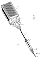
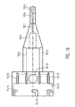
- Fig. 1
- ein perspektivische Darstellung einer erfindungsgemäßen Katheter-Vorrichtung,
- Fig. 2
- eine Explosionszeichnungen einer erfindungsgemäßen Katheter-Vorrichtung ,
- Fig. 3
- eine Schaftkappe der Katheter-Vorrichtung in einer seitlich geschnittenen Ansicht,
- Fig. 4
- ein distales Katheterschaftstück der Katheter-Vorrichtung in einer seitlich geschnit- tenen Ansicht,
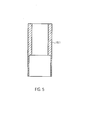
- Fig. 5
- eine Verbindungsbuchse der Katheter-Vorrichtung in einer seitlich geschnittenen Ansicht,
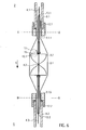
- Fig. 6
- eine Pumpe der Katheter-Vorrichtung mit Lagerung in einer seitlich geschnittenen Ansicht,
- Fig. 7a
- einen Schnitt entlang der Linie A-A durch die distale Verbindungsbuchse der Kathe- ter-Vorrichtung,
- Fig. 7b
- einen Schnitt entlang der Linie B-B durch die proximale Verbindungsbuchse der Ka- theter-Vorrichtung,
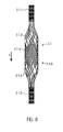
- Fig. 8
- eine Gitterstruktur eines Pumpengehäuses der Katheter-Vorrichtung,
- Fig. 9
- einen Ausschnitt der Gitterstruktur des Pumpengehäuses der Katheter-Vorrichtung,
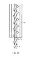
- Fig. 10
- eine Antriebswelle mit Führungsspirale und Wellenschutz der Katheter-Vorrichtung,
- Fig. 11a
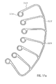
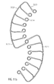
- eine Rahmenstruktur eines Rotors einer Pumpe der Katheter-Vorrichtung,
- Fig. 11b
- eine weitere Rahmenstruktur des Rotors der Pumpe der Katheter-Vorrichtung,
- Fig. 12
- den erfindungsgemäßen Rotor der Pumpe der Katheter-Vorrichtung in einer perspektivischen Ansicht,
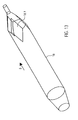
- Fig. 13
- einen Abströmschlauch der Katheter-Vorrichtung in einer perspektivischen Ansicht,
- Fig. 14
- eine erfindungsgemäße Kupplung mit Kupplungsgehäuse und Motor der Katheter- Vorrichtung in einer perspektivischen Ansicht,
- Fig. 15
- die erfindungsgemäße Kupplung mit dem Kupplungsgehäuse der Katheter- Vorrichtung in einer perspektivischen Ansicht,
- Fig. 16
- das Kupplungsgehäuse der Katheter-Vorrichtung in einer perspektivischen Ansicht,
- Fig. 17
- eine Vierkantstange der Kupplung der Katheter-Vorrichtung in einer seitlichen Ansicht,
- Fig. 18
- ein Kupplungselement der Kupplung der Katheter-Vorrichtung in einer seitlichen Ansicht,
- Fig. 19
- eine Abschlussscheibe der Kupplung der Katheter-Vorrichtung in einer seitlichen Ansicht,
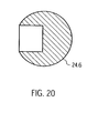
- Fig. 20
- eine Kugelkopflagerkugel der Kupplung der Katheter-Vorrichtung in einer seitlichen Ansicht,
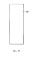
- Fig. 21
- einen Zentrierstift der Kupplung der Katheter-Vorrichtung in einer seitlichen Ansicht,
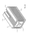
- Fig. 22
- eine Motoraufnahme der Katheter-Vorrichtung in einer seitlichen Ansicht,
- Fig. 23
- das Kupplungselement mit der darin angeordneten Vierkantstange in einer Draufsicht,
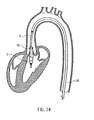
- Fig. 24
- die im Körper positionierte Katheter-Vorrichtung, und
- Fig. 25
- schematisch alternative Ausführungsformen der Katheter-Vorrichtung.
- Fig. 1
- a perspective view of a catheter device according to the invention,
- Fig. 2
- an exploded view of a catheter device according to the invention,
- Fig. 3
- a butt plate of the catheter device in a side view,
- Fig. 4
- a distal catheter shaft of the catheter device in a laterally cut view;
- Fig. 5
- a connector socket of the catheter device in a side-cut view,
- Fig. 6
- a pump of the catheter device with storage in a side-cut view,
- Fig. 7a
- 3 a section along the line AA through the distal connection bush of the catheter device,
- Fig. 7b
- 3 a section along the line BB through the proximal connection bushing of the catheter device,
- Fig. 8
- a lattice structure of a pump housing of the catheter device,
- Fig. 9
- a detail of the grid structure of the pump housing of the catheter device,
- Fig. 10
- a drive shaft with guide spiral and shaft protection of the catheter device,
- Fig. 11a
- a frame structure of a rotor of a pump of the catheter device,
- Fig. 11b
- another frame structure of the rotor of the pump of the catheter device,
- Fig. 12
- the rotor of the pump of the catheter device according to the invention in a perspective view,
- Fig. 13
- a discharge tube of the catheter device in a perspective view,
- Fig. 14
- a coupling according to the invention with coupling housing and motor of the catheter device in a perspective view,
- Fig. 15
- the coupling according to the invention with the coupling housing of the catheter device in a perspective view,
- Fig. 16
- the coupling housing of the catheter device in a perspective view,
- Fig. 17
- a square bar of the coupling of the catheter device in a side view,
- Fig. 18
- a coupling element of the coupling of the catheter device in a side view,
- Fig. 19
- a cover plate of the coupling of the catheter device in a side view,
- Fig. 20
- a ball-head bearing ball of the coupling of the catheter device in a side view,
- Fig. 21
- a centering pin of the coupling of the catheter device in a side view,
- Fig. 22
- a motor mount of the catheter device in a side view,
- Fig. 23
- the coupling element with the square rod arranged therein in a plan view,
- Fig. 24
- the catheter device positioned in the body, and
- Fig. 25
- schematically alternative embodiments of the catheter device.
Der Pumpenkopf 3 weist einen Rotor 3.2 zum Fördern eines Mediums in Förderrichtung 5 auf, der mit einer Antriebswelle 4 verbunden ist. Die Förderrichtung 5 ist vom distalen Ende 2 zu einem proximalen Ende 6 gerichtet. An dem vom Pumpenkopf 3 beabstandeten proximalen Ende 6 ist ein Motor 7 angeordnet. Die Antriebswelle 4 ist von einem Katheterschaft 8 umgeben und mittels einer Kupplung 9 kraftschlüssig mit dem Motor 7 verbunden.The
Nachfolgend wird zunächst der Pumpenkopf 3 näher erläutert. Der Pumpenkopf 3 umfasst eine Schaftkappe 10 am distalen Ende, den auf der Antriebswelle 4 angeordneten Rotor 3.2, ein Pumpengehäuse 3.1 und einen Abströmschlauch 18.Subsequently, the
Die Schaftkappe 10 ist aus einer Kugel 10.1 mit einem angesetzten zylinderförmigen Abschnitt 10.2 ausgebildet. Die Schaftkappe 10 ist beispielsweise aus Edelstahl ausgebildet (
Der Durchmesser der Kugel 10.1 beträgt in etwa 3.2 mm. Der zylinderförmige Abschnitt 10.2 ist in etwa 5,5 mm lang und hat einen Durchmesser von in etwa 2,2 mm. Die Gesamtlänge der Schaftkappe beträgt in etwa 7,0 mm.The diameter of the ball 10.1 is approximately 3.2 mm. The cylindrical portion 10.2 is about 5.5 mm long and has a diameter of about 2.2 mm. The total length of the butt plate is about 7.0 mm.
Der zylinderförmige Abschnitt 10.2 weist an seinem distalen Ende, im Anschlussbereich zur Kugel 10.1 eine quer zur Förderrichtung 5 angeordnete Durchgangsbohrung 10.3 auf. Weiterhin weist der Zylinder 10.2 eine axiale Bohrung 10.4 auf, die sich vom proximalen Ende des zylinderförmigen Abschnittes 10.2 bis zur Kugel 10.1 hin erstreckt, so dass ein kommunizierender Durchgang von der Durchgangsbohrung 10.3 bis zum proximalen Ende der Schaftkappe 10 ausgebildet ist. Im Bereich der axialen Bohrung 10.4 ist eine Stufe 10.5 ausgebildet, so dass die axiale Bohrung in Richtung des proximalen Endes aufgeweitet ist.The cylindrical portion 10.2 has at its distal end, in the connection region to the ball 10.1 a transversely to the conveying
Durch die Durchgangsbohrung 10.3 wird einerseits vermieden, dass in der Schaftkappe ein Sackloch entsteht und andererseits erlaubt das Durchgangsloch die Anbringung eines Fadens, der beim Komprimieren des Pumpenkopfes 3 hilfreich ist.By the through hole 10.3 on the one hand avoided that in the butt plate a blind hole is formed and on the other hand, the through hole allows the attachment of a thread that is helpful in compressing the
Anstelle der Kugel 10.1 der Schaftkappe 10 kann auch ein Pigtail, eine Spirale, ein mäanderförmiger Draht mit Kugelspitze oder ein atraumatisches Faserbündel vorgesehen sein. Die Schaftkappe ist aufgrund ihrer geringen Größe bevorzugt.Instead of the ball 10.1 of the
Die Spitze der Schaftkappe 10 ist eine atraumatische Kugel zum Schutz des Herzmuskels (Endocard). Über die Schaftkappe 10 kann der Pumpenkopf 3 an der Herzwand abgestützt werden.The tip of the
Ein rohrförmiges bzw. schlauchförmiges, distales Katheterschaftstück 8.1 ist vom proximalen Ende in die Schaftkappe 10 bis zur Stufe eingeführt. Das distale Katheterschaftstück 8.1 wird in der axialen Bohrung 10.4 passgenau aufgenommen und ist dort fixiert (
Das distale Katheterschaftstück 8.1 bildet eine gerade, aber leicht flexible Verbindung zwischen der Schaftkappe 10 und dem Pumpengehäuse 3.1. Die gerade Verbindung stellt eine Koaxialität aller in ihr angeordneten Bauteile (Antriebswelle, Wellenschutz, Gehäuse, Verbindungsbuchse) her.The distal catheter shaft 8.1 forms a straight but slightly flexible connection between the
Das distale Katheterschaftstück 8.1 dient in Verbindung mit der Schaftkappe 10 als Positionierungshilfe des Pumpenkopfes 3 beim Einbringen in ein Gefäß bzw. das Herz.The distal catheter shaft 8.1 is used in conjunction with the
Das Katheterschaftstück 8.1 im vorliegenden Ausführungsbeispiel weist eine Länge von in etwa 25 mm, einen Außendurchmesser von in etwa 1,9 mm und einen Innendurchmesser von in etwa 1,3 mm auf.The catheter shaft 8.1 in the present embodiment has a length of about 25 mm, an outer diameter of about 1.9 mm and an inner diameter of about 1.3 mm.
Am proximalen Ende des distalen Katheterschaftstücks 8.1 ist eine distale, röhrenförmige Verbindungsbuchse 12.1 vorgesehen (
Die distale Verbindungsbuchse 12.1 weist eine Länge von in etwa 5 mm und einen Außendurchmesser von in etwa 2,2 mm auf. Im distalen Bereich beträgt der Durchmesser in etwa 2 mm und im proximalen Bereich in etwa 1,5 mm. Je kürzer die Verbindungsbuchse ist, desto geringer ist die hierdurch bewirkte Aussteifung.The distal connection socket 12.1 has a length of about 5 mm and an outer diameter of about 2.2 mm. In the distal region the diameter is approximately 2 mm and in the proximal region approximately 1.5 mm. The shorter the connection bushing, the lower the resulting stiffening.
Die distale und eine analog ausgebildete proximale Verbindungsbuchse 12.1, 12.2 sind beispielsweise aus Edelstahl, Kupfer, Messing, Titan oder einem anderen geeigneten Metall, aus Polyethylen (PE), Polypropylen (PP), Teflon (PTFE), PEBAX, einem Polyether-Block-Amid, oder einem anderen geeigneten Material ausgebildet.The distal and an analogous trained proximal connection socket 12.1, 12.2 are for example made of stainless steel, copper, brass, titanium or other suitable metal, polyethylene (PE), polypropylene (PP), Teflon (PTFE), PEBAX, a polyether block Amide, or other suitable material formed.
Das expandierbare bzw. komprimierbare Pumpengehäuse 3.1 ist eine rohrförmig ausgebildete Gitterstruktur 3.1.6 aus Nitinol oder einer anderen geeigneten Gedächtnislegierung oder einem anderen Formgedächtnismaterial, z.B. Kunststoff, Eisenlegierung, Kupferlegierung. Das Pumpengehäuse 3.1 ist von distal nach proximal in fünf Abschnitte unterteilt (
Die Gitterstruktur 3.1.6 des Pumpengehäuses 3.1 weist zwischen den Gitterstreben Öffnungen 3.1.7 auf (
Die Gitterstruktur 3.1.6 des Pumpengehäuses 3.1 ist im Pumpenabschnitt 3.1.3 mit einer PU-Bespannung 3.1.8 bespannt, wodurch die Gitteröffnungen flüssigkeitsdicht verschlossen sind. Diese Bespannung bzw. die Abdichtung der Gitterstruktur 3.1.6 kann auch z.B. durch einen PU-Schlauch der auf der Oberfläche außen oder innen angeordnet ist, ausgebildet sein.The lattice structure 3.1.6 of the pump housing 3.1 is covered in the pump section 3.1.3 with a PU covering 3.1.8, whereby the grid openings are sealed liquid-tight. This covering or the sealing of the lattice structure 3.1.6 can also be formed, for example, by a PU tube which is arranged on the surface outside or inside.
Es kann auch eine andere Bespannung als PU verwendet werden, wie z.B. PE, PP, Silikon oder Parylene, solange sie die mechanischen und geometrischen Anforderungen erfüllt.It is also possible to use a covering other than PU, such as e.g. PE, PP, silicone or parylene, as long as it meets the mechanical and geometric requirements.
Durch die Auswahl einzelner Öffnungen 3.1.71, insbesondere der mittleren und größeren Öffnungen 3.1.7.3, 3.1.7.2, die nicht beschichtet werden, können die Leistungsparameter inkl. Blutschädigung der Pumpe gezielt gesteuert werden.By selecting individual openings 3.1.71, in particular the middle and larger openings 3.1.7.3, 3.1.7.2, which are not coated, the performance parameters including blood damage to the pump can be controlled specifically.
Durch die polygonale Struktur und die besondere Ausführung der PU-Bespannung ergibt sich eine annähernd runde Querschnittsform für das Pumpengehäuse 3.1. In Verbindung mit dem runden Rotor 3.2 ergeben sich dadurch sehr geringe Spalte zwischen Rotor 3.2 und Pumpengehäuse 3.1. Dies führt zu vergleichsweise niedriger Blutschädigung, niedrigen Leckströmen und einem guten Wirkungsgrad. Durch die Gitterstruktur 3.1.6 ergibt sich eine sehr gute radiale und axiale Stabilität sowie eine sehr gute axiale Komprimierbarkeit und Expandierbarkeit. Durch die spezielle Struktur kann sehr einfach eine Anpassung von Länge und Durchmesser an die Leistungsanforderungen erfolgen.Due to the polygonal structure and the special design of the PU covering results in an approximately round cross-sectional shape for the pump housing 3.1. In conjunction with the round rotor 3.2, this results in very small gaps between the rotor 3.2 and the pump housing 3.1. This leads to comparatively low blood damage, low leakage currents and good efficiency. By the lattice structure 3.1.6 results in a very good radial and axial stability and a very good axial compressibility and expandability. The special structure makes it very easy to adapt the length and diameter to the performance requirements.
Der proximale Verbindungsabschnitt 3.1.5 des Pumpengehäuses 3.1 ist in der proximalen Verbindungsbuchse 12.2 aufgenommen und mit dieser verbunden. In der proximalen Verbindungsbuchse 12.2 ist analog zur distalen Verbindungsbuchse 12.1 ein schlauchförmiges proximales Katheterschaftstück 8.2 aufgenommen und mit dieser verbunden (
Innerhalb des distalen und des proximalen Katheterschaftstückes 8.1, 8.2 ist in axialer Richtung ein distaler Wellenschutz 13.1 und ein proximaler Wellenschutz 13.2 angeordnet (
Der distale Wellenschutz 13.1 erstreckt sich in Förderichtung 5 von kurz vor der distalen Verbindungsbuchse 12.1 bis zum distalen Ende des Pumpenabschnitts 3.1.3 des Pumpengehäuses 3.1, d.h. bis zum Rotor 3.2. Der proximale Wellenschutz 13.2 erstreckt sich vom proximalen Ende des Rotors 3.2 bis kurz hinter das proximale Ende der proximalen Verbindungsbuchse 12.1.The distal shaft protection 13.1 extends in the direction of
Der distale und der proximale Wellenschutz 13.1, 13.2 sind in den beiden Bereichen, in denen sie innerhalb der distalen und der proximalen Verbindungsbuchse 12.1, 12.2 bzw. des distalen und des proximalen Katheterschaftstücks 8.1, 8.2 angeordnet sind, mit diesen verbunden.The distal and the proximal shaft protection 13.1, 13.2 are in the two areas in which they are disposed within the distal and the proximal connection sleeve 12.1, 12.2 and the distal and proximal catheter shaft 8.1, 8.2, connected to these.
Die beiden Verbindungsbuchsen 12.1, 12.2 bilden zusammen mit den darin angeordneten Bauteilen (Wellenschutz, Pumpengehäuse, Katheterschaft) einen Lagerbereich für die Antriebswelle 4. Die Verbindungsbuchsen 12.1, 12.2 gewährleisten die Achszentriertheit der Antriebswelle 4 insbesondere im Pumpengehäuse 3.1.The two connection sockets 12.1, 12.2 together with the components arranged therein (shaft protection, pump housing, catheter shaft) a bearing area for the
Innerhalb des distalen und des proximalen Wellenschutzes 13.1, 13.2 bzw. des Pumpengehäuses 3.1 ist in axialer Richtung die Antriebswelle 4 angeordnet. Die Antriebswelle 4 weist in Förderichtung 5 drei Abschnitte auf. Einen distalen Abschnitt der Antriebswelle 4.1 im Bereich der Schaftkappe 10. Einen Pumpenabschnitt der Antriebswelle 4.2, auf dem der Rotor 3.2 drehfest angeordnet ist und einen proximalen Abschnitt der Antriebswelle 4.3, der sich vom Pumpenabschnitt 3.1.3 bis hin zur Kupplung 9 erstreckt. Der Rotor 3.2. ist mit der Antriebswelle verklebt. Es können jedoch auch andere kraftschlüssige Verbindungen wie Schweißen oder Klemmen vorgesehen sein.Within the distal and the proximal shaft protection 13.1, 13.2 and the pump housing 3.1, the
Der proximale Wellenschutz 13.1 (
Die Antriebswelle 4 ist bevorzugt aus mehreren, insbesondere sechs Drähten (nicht dargestellt), die links- oder rechtsgewickelt um eine Seele (nicht dargestellt) angeordnet sind, ausgebildet. Der Außendurchmesser der Antriebswelle 4 beträgt in etwa 0,48 mm. Die Antriebswelle 4 kann aber auch eine andere Anzahl von Seelen und Drähten aufweisen und einen kleineren oder einen größeren Durchmesser aufweisen. Der Durchmesser der Antriebswelle kann im Bereich von 0,3 mm bis 1 mm liegen und beträgt vorzugsweise etwa 0,4 mm bis 0,6 mm. Je kleiner der Durchmesser der Antriebswelle ist, desto größer kann die Drehgeschwindigkeit sein, denn je kleiner der Durchmesser ist, desto geringer ist die Geschwindigkeit, mit der sich der Umfang der Antriebswelle gegenüber seiner Umgebung bewegt. Eine hohe Umfangsgeschwindigkeit ist problematisch, wenn die Antriebswelle mit der Umgebung in Berührung kommt. Die Katheter-Vorrichtung ist für Drehzahlen von mehr als 20.000 U/min und bis zu 40.000 U/min ausgelegt. Daher wird der Durchmesser der Antriebswelle 4 so gering wie möglich ausgebildet, aber so dick, dass sie noch eine ausreichende Festigkeit besitzt.The
Entgegen der Wickelrichtung der Antriebswelle 4 - im vorliegenden Ausführungsbeispiel ist sie links gewickelt - ist in axialer Richtung um den distalen und den proximalen Abschnitt der Antriebswelle 4.1, 4.3 ein entgegengesetzt gewickelte (hier: rechtsdrehend), spiralförmig ausgebildete Führungsspirale 14 angeordnet, um die Reibung der Antriebswelle 4 zu minimieren, den Wandkontakt der Antriebswelle 4 mit dem proximalen Katheterschaftstück 8.2 zu vermeiden sowie ein Abknicken der Antriebswelle 4 in Folge von Biegung zu verhindern. Durch die Führungsspirale 14 wird die Antriebswelle 4 geführt und geschient bzw. stabilisiert (
Die Antriebswelle 4 erstreckt sich vom distalen Ende des distalen Wellenschutzes 13.1 in Förderrichtung 5 hinter der distalen Verbindungsbuchse 12.1 bis hin zur Kupplung 9.The
Das proximale Katheterschaftstück 8.2 stellt in Verbindung mit der Führungsspirale 14 eine längen-und verwindungskonstante Verbindung zwischen dem Pumpenkopf 3 und der Kupplung 9 bereit.The proximal catheter shaft 8.2, in conjunction with the
Am proximalen Ende des distalen Wellenschutzes 13.1 ist eine Lagerscheibe 15 angeordnet (
Die Lagerscheibe 15 ist beispielsweise aus Edelstahl, Teflon oder Keramik bzw. einem anderen geeigneten Material ausgebildet. Die Lagerscheibe 15 ist mittels Cyanacrylatkleber mit dem feststehenden Wellenschutz verbunden und kann daher Axialkräfte entgegen der Förderichtung 5 aufnehmen (Verbindungsmittel s.o.).The bearing
Im Pumpenabschnitt 4.2 der Antriebswelle 4 ist der spiralförmige, expandierbare Rotor 3.2 drehfest auf der Antriebswelle 4 angeordnet. Als Rotor 3.2 ist im vorliegenden Ausführungsbeispiel eine zweiflügelige, kammförmig ausgebildete Rahmenstruktur 3.2.1 aus Nitinol oder einem anderen Formgedächtnismaterial, z.B. Kunststoff (s.o.) vorgesehen, die mit einer PU-Haut beschichtet bzw. von dieser flüssigkeitsdicht umgeben ist (
Die Rahmenstruktur 3.2.1 weist einen umlaufenden, schraubenförmigen bzw. spiralförmigen äußeren Begrenzungsrahmen 3.2.2 mit mehreren mit dem Begrenzungsrahmen 3.2.2 und radial nach innen verlaufenden Rotorstreben 3.2.3 auf (
Zwischen zwei benachbarten Ringen 3.2.4 ist jeweils eine Abstandshülse 16 angeordnet. Das distale Ende des Rotors 3.2 liegt mit einer distal endseitigen Abstandshülse 16 an der Lagerscheibe 15 an. Die endseitige Abstandshülse 16 kann auch als spezielle Lagerabstandshülse 16 ausgebildet sein. Auf diese Weise bilden zwei der Rahmenstrukturen 3.2.1 einen zweiflügeligen Rotor 3.2 aus.Between two adjacent rings 3.2.4 a
Der Rotor 3.2 kann auch einteilig (
Der Abstand zwischen zwei benachbarten Ringen 3.2.4 ist kleiner als der entsprechende Abschnitt des spiralförmigen Begrenzungsrahmens 3.2.2. Je größer die Differenz zwischen dem Abstand zwischen zwei Ringen 3.2.4 und dem entsprechenden Abschnitt des spiralförmigen Begrenzungsrahmens 3.2.2 ist, desto größer ist die Steigung des Rotors. Durch die Länge der Abstandshülsen 16 kann somit die Steigung des Rotors 3.2 festgelegt werden. Sie kann innerhalb eines Rotors 3.2 variieren.The distance between two adjacent rings 3.2.4 is smaller than the corresponding portion of the spiral bounding box 3.2.2. The greater the difference between the distance between two rings 3.2.4 and the corresponding portion of the spiral bounding frame 3.2.2, the greater the pitch of the rotor. By the length of the
Durch die Länge bzw. Anzahl der Abstandshülsen 16 im Verhältnis zur Dimensionierung des umlaufenden, spiralförmigen äußeren Begrenzungsrahmens 3.2.2 zwischen zwei Rotorstreben 3.2.3 wird die Steigung des Rotors 3.2 festgelegt. Die Länge der Abstandshülsen 16 kann für alle Positionen einheitlich sein, sie kann aber auch symmetrisch oder asymmetrisch für jede Position variiert werden. Durch die völlige Gestaltungsfreiheit kann ein sehr flexibles Design des Rotors 3.2 erreicht werden. Durch das flexible Design ist es möglich, unterschiedliche Förder- bzw. Pumpeigenschaften des Rotors 3.2 zu generieren.By the length or number of
Der Rotor 3.2 weist eine hohe Formstabilität bei flexibler Gestaltungsmöglichkeit und bei minimalem Materialeinsatz (z.B. dünne Rahmenstruktur) auf. Es wird eine maximale Steifigkeit und Stabilität erreicht. Trotzdem erlaubt die Kombination aus der Rahmenstruktur mit der Bespannung, die die Eigenschaften der Rahmenstruktur durch Stabilisierung weiter unterstützt, eine sehr starke Komprimierung. Dies führt zu der sehr guten Komprimierbarkeit und Expandierbarkeit des Rotors. Aufgrund der guten Flächenausbildung der PU-Haut auf der Gitterstruktur ist eine sehr gute Anpassung der Gehäusestruktur an die Rotorstruktur möglich.The rotor 3.2 has a high dimensional stability with a flexible design possibility and with minimum use of material (for example a thin frame structure). It achieves maximum rigidity and stability. Nevertheless, the combination of the frame structure with the string, which further supports the properties of the frame structure by stabilization, allows very high compression. This leads to the very good compressibility and expandability of the rotor. Due to the good surface formation of the PU skin on the lattice structure, a very good adaptation of the housing structure to the rotor structure is possible.
Der Rotor 3.2 weist im komprimierten Zustand in etwa den Innendurchmesser des komprimierten Pumpengehäuses 3.1 auf. Der Außendurchmesser des komprimierten Pumpengehäuses beträgt in etwa zwischen 2 mm bis 4 mm und vorzugsweise in etwa 3,3 mm.The rotor 3.2 has approximately the inner diameter of the compressed pump housing 3.1 in the compressed state. The outer diameter of the compressed pump housing is approximately between 2 mm to 4 mm, and preferably about 3.3 mm.
Im expandierten Zustand ist der spiralförmige äußere Begrenzungsrahmen 3.2.2 des Rotors 3.2 geringfügig beabstandet zur Innenfläche des Pumpengehäuses 3.1. Der Abstand zwischen dem äußeren Begrenzungsrahmen 3.2.2 und der Innenfläche des Pumpengehäuses 3.1 beträgt in etwa zwischen 0,01 mm und 0,5 mm. Je kleiner der Abstand zwischen der Rahmenstruktur 3.2.1 und der Innenfläche des Pumpengehäuses 3.1 ist, desto höher ist die Förderleistung des Rotors 3.2.In the expanded state of the spiral outer boundary frame 3.2.2 of the rotor 3.2 is slightly spaced from the inner surface of the pump housing 3.1. The distance between the outer boundary frame 3.2.2 and the inner surface of the pump housing 3.1 is approximately between 0.01 mm and 0.5 mm. The smaller the distance between the frame structure 3.2.1 and the inner surface of the pump housing 3.1, the higher the delivery rate of the rotor 3.2.
An der distal endseitigen Abstandshülse 16 des Rotors berühren sich die am distalen Wellenschutz 13.1 befestigte Lagerscheibe 15 und die distal endseitige Abstandshülse 16, die beide auf der Antriebswelle 4 angeordnet sind. Indem der Rotor 3.2 durch die Antriebswelle 4 in eine Drehbewegung versetzt wird, kontaktiert die distale Abstandshülse 16 des Rotors 3.2 die Lagerscheibe 15 in Art eines Gleitlagers. Auf diese Weise ist ein distales Rotorlager 17 ausgebildet (
Beim Pumpen wird der Rotor 3.2 aufgrund der Förderung des Pumpmediums mit einer axialen Kraft entgegen der Förderrichtung 5 belastet. Diese Kraft wird über die distal endseitige Abstandshülse 16 auf die Lagerscheibe 15 abgeleitet.When pumping the rotor 3.2 is charged due to the promotion of the pumping medium with an axial force against the conveying
Zum Schmieren des distalen Rotorlagers wird über die Durchgangsbohrung 10.3 der Schaftkappe 10, den Freiräumen zwischen dem distalen Wellenschutz 13.1 und der Antriebswelle 4 und dem Freiraum zwischen der Antriebswelle und der Lagerscheibe 15 Blut bzw. Serum eingesogen. Die Sogwirkung entsteht aufgrund der Drehbewegung der Antriebswelle 4 und des Rotors 3.2.For lubricating the distal rotor bearing, blood or serum is drawn in through the
An der proximal endseitigen Abstandshülse 16 des Rotors 3.2 wird die Antriebswelle 4 analog von einer proximalen Verbindungsbuchse 12.2 aufgenommen.At the proximal end-
In etwa am proximalen Ende des Pumpenabschnitts 3.1.3 des Pumpengehäuses ist ein rohrförmiger elastischer Abströmschlauch 18 angeordnet (
Das distale konisch zulaufende Ende des Abströmschlauches 18 schließt dicht mit der PU-Bespannung des Pumpenabschnittes 3.1.3 des Pumpengehäuses 3.1 ab. Der zylinderförmige proximale Abschnitt ist fest mit dem proximalen Katheterschaftstück 8.2 verbunden. Beide sind mittels gelöstem PU miteinander flüssigkeitsdicht verbunden.The distal conically tapered end of the
Am proximalen Ende des Abströmschlauches 18 sind radial umlaufend mehrere Auslassöffnungen 18.1 angeordnet. Die Auslassöffnungen 18.1 können z.B. in Förderrichtung 5 oval ausgebildet sein. Es kann auch vorgesehen sein die Auslassöffnungen rund, halbmondförmig bzw. in einer beliebigen Geometrie auszubilden um andere Auslassströmungen zu generieren. Die Auslassöffnungen 18.1 verwirbeln das in den Bulbus Aorticus austretende Blut. Dadurch wird eine laminare Strömung und damit der Wasserstrahlpumpenefekt gegenüber den Koronararterien verhindert.At the proximal end of the discharge hose 18 a plurality of outlet openings 18.1 are arranged radially circumferentially. The outlet openings 18.1 may be e.g. be formed in the conveying
Der Abströmschlauch 18 leitet das Pumpvolumen der Pumpe aus dem linken Ventrikel über die Aortenklappe in die Aorta. Hierbei wirkt der Abströmschlauch 18 wie ein Rückschlagventil. Bei positiver Druckdifferenz zwischen Abströmschlauch 18 und Aorta ist der Abströmschlauch 18 entsprechend der von der Pumpe erzeugten Durchflussmenge mehr oder weniger geöffnet. Bei Null oder negativer Druckdifferenz schließt sich der Abströmschlauch 18 aufgrund seiner hohen Flexibilität genau wie die Aortenklappe und legt sich eng an das proximale Katheterschaftstück 8.2 an. Diese Flexibilität führt zu einer guten Abdichtung während der Durchströmung gegenüber den Segeln der Aortenklappe. Auf diese Weise kommt es lediglich zu geringen Rückflüssen aus der Aorta in den linken Ventrikel.
Am proximalen Ende des Katheterschaftes 8.2 sind die Kupplung 9 und der Motor 7 angeordnet. Der Abstand zwischen dem Pumpenkopf 3 und der Kupplung 9 bzw. die Länge des proximalen Katheterschaftstücks 8.2 kann je nach Patient variieren und beträgt in etwa 90 bis 150 cm.At the proximal end of the catheter shaft 8.2, the
Nachfolgend wird das Verfahren zum Expandieren des Rotors 3.2 beschrieben.Hereinafter, the method for expanding the rotor 3.2 will be described.
Über der Katheter-Vorrichtung 1 ist ein rohrförmiger Deckschlauch 29 angeordnet. Der Deckschlauch 29 ist derart ausgebildet, dass er den komprimierten Pumpenkopf 3 sowie das proximale Katheterschaftstück 8.2 umgibt. Durch den Deckschlauch 29 wird der Pumpenkopf 3 in seinem komprimierten Zustand gehalten.Above the
Nach der korrekten Positionierung des Pumpenkopfes 3 wird der Deckschlauch 29 von der fixierten Katheter-Vorrichtung 1 zurückgezogen, bis der Pumpenkopf 3 frei liegt. Pumpengehäuse 3.1 und Rotor 3.2 entfalten sich aufgrund der Federkraft des elastischen Materials radial nach außen. Das heißt, die Gitterstruktur 3.1.6 des Pumpengehäuses 3.1 und die Rahmenstruktur 3.2.1 des Rotors 3.2 weiten sich auf bis sie ihren vorgegebenen Durchmesser erreicht haben. Es kann auch vorgesehen sein Temperatureffekte des Memory-Materials beim Expandieren unterstützend zu nutzen.After the correct positioning of the
Zur Entfernung der Katheter-Vorrichtung 1 wird der Deckschlauch 29 bis zur Schaftkappe 10 vorgeschoben, wodurch der Rotor 3.2 und das Pumpengehäuse 3.1 komprimiert werden und in den Deckschlauch eingezogen werden, wonach dieser durch die Punktionsstelle hindurch extrahiert wird.To remove the
Nachfolgend werden die Kupplung 9 und der Motor 7 erläutert.Hereinafter, the
Die Kupplung 9 ist eine Magnetkupplung (
Die distale Magneteinheit 23.1 und die proximale Magneteinheit 23.2 sind über Magnetkräfte drehfest miteinander gekoppelt. Durch die beiden Magneteinheiten 23.1, 23.2 wird eine eine kraftschlüssige Verbindung bei berührungfreier rotatorischer Kraftübertragung gewährleistet.The distal magnet unit 23.1 and the proximal magnet unit 23.2 are coupled to one another in a rotationally fixed manner via magnetic forces. By the two magnet units 23.1, 23.2 a frictional connection is ensured with contact-free rotary power transmission.
Das Kupplungsgehäuse 19 weist von distal nach proximal einen distalen zylinderförmigen Abschnitt 19.1, einen sich konisch aufweitenden Abschnitt 19.2, einen zweiten zylinderförmigen Abschnitt 19.3 und einen proximalen zylinderförmigen Abschnitt 19.4 auf. Das Kupplungsgehäuse ist z.B. aus Polymethylacrylat (PMMA) ausgebildet oder einem anderen spritzgussfähigen oder zu spanenden Material hergestellt.The coupling housing 19 has from distal to proximal a distal cylindrical portion 19.1, a conically widening portion 19.2, a second cylindrical portion 19.3 and a proximal cylindrical portion 19.4. The coupling housing is For example, made of polymethyl acrylate (PMMA) or another injection-moldable or produced material to be cut.
Im distalen zylinderförmigen Abschnitt 19.1 ist eine in axialer Richtung mittig angeordnete Durchgangsbohrung ausgebildet. Die Durchgangsbohrung erstreckt sich durch das gesamte Kupplungsgehäuse 19.In the distal cylindrical portion 19.1 a centrally disposed in the axial direction through hole is formed. The through hole extends through the entire coupling housing 19th
Vom distalen Ende des distalen zylinderförmigen Abschnitts 19.1 verengt sich die Durchgangsbohrung dreistufig von einem ersten Katheterschaftaufnahmeabschnitt 19.5 auf einen zweiten Führungsspiraleaufnahmeabschnitt 19.6 und auf einen dritten Antriebswellendurchtrittsabschnitt 19.7.From the distal end of the distal cylindrical portion 19.1, the through hole narrows in three stages from a first catheter shaft receiving portion 19.5 to a second guide coil receiving portion 19.6 and to a third drive shaft passage portion 19.7.
Der Bohrungsdurchmesser des Katheterschaftaufnahmeabschnitts 19.5 beträgt in etwa 1,9 mm, der des Führungsspiraleaufnahmeabschnitts 19.6 in etwa 1,28 mm und der des dritten Bohrungsabschnitts in etwa 1,0 mm.The bore diameter of the catheter shaft receiving portion 19.5 is about 1.9 mm, that of the guide spiral receiving portion 19.6 is about 1.28 mm and that of the third bore portion is about 1.0 mm.
Das proximale Ende des proximalen Katheterschaftes ist im Katheterschaftaufnahmeabschnitt 19.5 des Kupplungsgehäuses 19 angeordnet und mit diesem fest verbunden. Im Führungsspiraleaufnahmeabschnitt 19.6 ist die Führungsspirale 14 aufgenommen.The proximal end of the proximal catheter shaft is disposed in the catheter shaft receiving portion 19.5 of the clutch housing 19 and fixedly connected thereto. In the guide spiral receiving portion 19.6, the
Die Antriebswelle 4 erstreckt sich durch die Durchgangsbohrung des Antriebswellendurchtrittsabschnitts 19.7 des distalen zylinderförmigen Abschnitts 19.1 und des sich konisch aufweitenden Abschnitts 19.1, 19.2. Der Antriebswellendurchtrittsabschnitt 19.7 weitet sich im sich konisch aufweitenden Abschnitt 19.2 in einen vierten Bohrungsabschnitt 19.8 auf.The
Der vierte Bohrungsabschnitt geht zu Beginn des zweiten zylinderförmigen Abschnitts 19.3 in einen hohlzylindrischen Lagerungsabschnitt 19.9 über. Im distalen Endbereich des Lagerungsabschnitts 19.9 ist ein äußerer Ringmagnet 20.1 angeordnet. Der äußere Ringmagnet 20.1 ist über eine Presspassung in der Bohrung des Lagerungsabschnitts 19.9 fixiert und kann zusätzlich oder alternativ mittels einer Klebung fixiert sein.The fourth bore section merges into a hollow cylindrical bearing section 19. 9 at the beginning of the second cylindrical section 19. In the distal end region of the storage section 19.9 an outer ring magnet 20.1 is arranged. The outer ring magnet 20.1 is fixed via a press fit in the bore of the bearing section 19.9 and can additionally or alternatively be fixed by means of an adhesive bond.
Der Lagerungsabschnitt 19.9 weist einen Durchmesser von in etwa 10 mm auf.The storage section 19.9 has a diameter of about 10 mm.
Am Anfang des proximalen zylinderförmigen Abschnitts 19.4 des Kupplungsgehäuses 19 geht die Bohrung des Lagerungsabschnitts 19.9 in einen größeren sechsten distalen Kupplungsabschnitt 19.10 über. Im distalen Kupplungsabschnitt 19.10 ist eine radial angeordnete Spülbohrung 19.15 ausgebildet.At the beginning of the proximal cylindrical portion 19.4 of the coupling housing 19, the bore of the bearing portion 19.9 merges into a larger sixth distal coupling portion 19.10. In the distal coupling section 19.10, a radially arranged flushing bore 19.15 is formed.
An der Spülbohrung ist eine Pumpe (nicht dargestellt) zum Einbringen eines Mediums, z.B. NaCl, Glukoselösung, Ringerlösung, Plasmaexpander, etc. angeschlossen.At the flushing bore is a pump (not shown) for introducing a medium, e.g. NaCl, glucose solution, Ringer's solution, plasma expander, etc. connected.
Die Bohrung des distalen Kupplungsabschnitts 19.10 geht in einen größeren proximalen Kupplungsabschnitt 19.11 über. Im zwischen dem distalen und dem proximalen Kupplungsabschnitt 19.10, 19.11 ausgebildeten Absatz 19.12 sind radial symmetrisch 8 x M 1,6 Gewindebohrungen 19.13 ausgebildet. Am proximalen Ende des proximalen Abschnitts 19.4 sind drei L-förmige Ausfräsungen 19.14, auf den Umfang verteilt, angeordnet.The bore of the distal coupling portion 19.10 merges into a larger proximal coupling portion 19.11. In between the distal and the proximal coupling portion 19.10, 19.11 formed paragraph 19.12 8 x M 1.6 threaded holes 19.13 are radially symmetrical. At the proximal end of the proximal portion 19.4 three L-shaped cutouts 19.14, distributed around the circumference, arranged.
Der distale Kupplungsabschnitt 19.10 weist einen Durchmesser von in etwa 22 mm auf. Die Spülbohrung 19.15 weist einen Durchmesser von in etwa 6,5 mm auf und der proximale Kupplungsabschnitt 19.11 weist einen Durchmesser von in etwa 30 mm auf.The distal coupling portion 19.10 has a diameter of about 22 mm. The flushing bore 19.15 has a diameter of about 6.5 mm and the proximal coupling portion 19.11 has a diameter of about 30 mm.
Das proximale Ende der Antriebswelle 4 ist dreh, zug- und druckfest (kraftschlüssig) mit einer quaderförmigen Vierkantstange 21 verbunden (
Die Vierkantstange 21 weist eine Länge von in etwa 19,4 mm und einen Querschnitt von in etwa 2,88 mm x 2,88 mm auf.The
Die Vierkantstange 21 überträgt die Drehbewegung des Motors auf die Antriebswelle. Die Vierkantstange 21 kann jede beliebige geometrische Form aufweisen, die einen statisch bestimmten Krafteintrag ermöglicht.The
Die Vierkantstange 21 wird von einer axialen Ausnehmung 22.1 innerhalb eines rotationssymmetrischen Kupplungselements 22 axial verschiebbar aufgenommen (
Durch die Anordnung der Bohrungen werden vier axial verlaufende Doppelanschlagkanten bereitgestellt. Die Ausnehmung 22.1 ist innerhalb eines zylinderförmigen Abschnitts 22.2 des Kupplungselements 22 angeordnet und erstreckt sich vom distalen Ende des Kupplungselements 22 bis kurz vor einen scheibenförmigen proximalen Abschnitt 22.3 des Kupplungselements 22.The arrangement of the holes four axially extending double stop edges are provided. The recess 22.1 is within a cylindrical portion 22.2 of the
Der zylinderförmige Abschnitt 22.2 weist einen Außendurchmesser von in etwa 8 mm auf und der scheibenförmige Abschnitt 22.3 weist einen Außendurchmesser von in etwa 18 mm auf.The cylindrical portion 22.2 has an outer diameter of about 8 mm and the disc-shaped portion 22.3 has an outer diameter of about 18 mm.
Die Ausnehmung 22.1 ist derart ausgebildet, dass die Vierkantstange 21 radial bzw. in Umfangsrichtung fixiert und axial verschieblich aufgenommen wird. Die radiale Fixierung der Vierkantstange 21 erfolgt durch die Kontaktierung aller vier Längskanten der Vierkantstange 21 mit jeweils einer der vier Doppelanschlagkanten der Ausnehmung 22.1. Bei einer axialen Verschiebung der Vierkantstange 21 in der Ausnehmung 22.1 ergibt sich an den entsprechenden Berührungslinien nur eine minimale Reibung.The recess 22.1 is formed such that the
Es können auch mehr oder weniger Anschlagkanten vorgesehen sein. Anstelle einer Vierkantstange kann z.B auch eine Dreikant- oder Fünfkantstange oder eine Profilstange mit einer an sich beliebigen in Längsrichtung der Stange gleich bleibender Querschnittsfläche vorgesehen sein. Die Ausnehmung 22.1 ist in der Form entsprechend an die Querschnittsfläche der Profilstange anzupassen.It can also be provided more or less stop edges. Instead of a square bar, for example, a triangular or pentagonal bar or a profile bar can be provided with any cross-sectional area which remains constant in the longitudinal direction of the bar. The recess 22.1 is to be adapted in shape corresponding to the cross-sectional area of the profile bar.
Am distalen äußeren Ende bzw. Umfang des zylinderförmigen Abschnitts 22.2 des Kupplungselements 22 ist ein Absatz 22.4 ausgebildet. Auf diesem Absatz 22.4 ist ein zweiter innerer Ringmagnet 20.2 angeordnet. Der Absatz 22.4 nimmt den Ringmagneten 20.2 derart auf, dass dessen Außenfläche bündig mit der Mantelfläche des zylinderförmigen Abschnittes 22.2 abschließt. Dieser bildet in Verbindung mit dem im Lagerungsabschnitt 19.9 des Kupplungsgehäuses 19 entsprechend ihn umgebenden äußeren Ringmagneten 20.1 ein Magnetringlager 20.3 aus.At the distal outer end or circumference of the cylindrical portion 22.2 of the
Im Magnetringlager 20.3 sind die beiden Ringmagnete 20.1, 20.2 derart angeordnet, dass z.B. der Nordpol des äußeren Ringmagnet nach distal und der Südpol nach proximal ausgerichtet ist. Der Nord- und der Südpol des inneren Ringmagneten sind entsprechend entgegengesetzt ausgebildet. Entsprechend können die Nord- und Südpole der beiden Ringmagneten auch umgekehrt angeordnet sein. Das Magnetringlager 20.3 zentriert die Antriebswelle 4 in axialer und in radialer Richtung. Die radiale Zentrierung erfolgt durch die magnetischen Anziehungskräfte in radialer Richtung. Die axiale Zentrierung erfolgt dadurch, dass bei einem kleinen Versatz des inneren Ringmagneten 20.2 magnetische Rückstellkräfte erzeugt werden, die den inneren Ringmagneten 20.2 in eine in Axialrichtung mit der Position des äußeren Ringmagneten 20.1 übereinstimmende Stellung ziehen. Bei einem größeren Versatz treten hingegen Abstoßungskräfte zwischen den beiden Magnetringen 20.1 und 20.2 auf, wodurch sie auseinander gedrückt werden.In the magnetic ring bearing 20.3, the two ring magnets 20.1, 20.2 are arranged such that, for example, the north pole of the outer ring magnet is oriented distally and the south pole is oriented proximally. The north and the south pole of the inner ring magnet are formed correspondingly opposite. Accordingly, the north and south poles of the two ring magnets can also be arranged vice versa. The magnetic ring bearing 20.3 centers the
Im Magnetringlager 20.3 berühren sich die Ringmagneten 20.1, 20.2 nicht, d.h. es ist keine Schmierung erforderlich. Zudem wirkt das Magnetringlager schwingungsdämpfend.In the magnetic ring bearing 20.3, the ring magnets 20.1, 20.2 do not touch, i. no lubrication is required. In addition, the magnetic ring bearing dampens vibration.
Am proximalen Ende des Kupplungselements ist im scheibenförmigen Abschnitt 22.3 des Magnetkupplungselements 22 eine Magnetaufnahme 22.5 ausgebildet. Die Magnetaufnahme 22.5 ist eine zentrische zirkuläre Ausfräsung.At the proximal end of the coupling element, a magnet receptacle 22.5 is formed in the disk-shaped section 22.3 of the
Die zentrische zirkuläre Ausfräsung 22.5 weist einen Durchmesser von in etwa 16,5 mm und eine Tiefe von in etwa 3 mm auf.The central circular cutout 22.5 has a diameter of about 16.5 mm and a depth of about 3 mm.
Die Magnetaufnahme 22.5 nimmt die aus vier Segmenten bestehende ringförmige distale Magneteinheit 23.1 auf. Die ringförmige distale Magneteinheit ist in die Magnetaufnahme 22.5 eingeklebt.The magnet holder 22.5 accommodates the four-segment annular distal magnet unit 23.1. The annular distal magnet unit is glued into the magnet holder 22.5.
In der proximalen Stirnseite des Kupplungselements 22 ist mittig eine Kugelkopflageraufnahme 22.7 ausgebildet. Die Kugelkopflageraufnahme 22.7 ist eine etwa halbkugelförmige Ausnehmung 22.7.In the proximal end face of the
Die halbkugelförmige Ausnehmung 22.7 weist einen Durchmesser von in etwa 0,5 bis 1,3 mm auf.The hemispherical recess 22.7 has a diameter of about 0.5 to 1.3 mm.
Die Vierkantstange 21 bzw. der zylinderförmige Abschnitt des Kupplungselements 22 wird vom vierten Bohrungsabschnitt 19.8 bzw. vom Lagerungsabschnitt 19.9 des Kupplungsgehäuses 19 aufgenommen. Der scheibenförmige Abschnitt 22.3 des Kupplungselements 22 wird vom distalen Kupplungsabschnitt 19.10 des Kupplungsgehäuses 19 aufgenommen.The
Das Kupplungsgehäuse 19 wird durch eine Abschlussscheibe 24 hermetisch von der Motoranordnung getrennt (
Die Abschlussscheibe 24 ist auf dem Absatz 19.12 des Kupplungsgehäuses 19 angeordnet und ist mittels acht Schrauben fixiert, die entsprechend von radiär symmetrisch in der Abschlussscheibe 24 angeordneten Bohrungen 24.1 aufgenommen sind und in den Gewindebohrungen 19.13 des Kupplungsgehäuses 19 verschraubt sind. Diese Verbindung ist flüssigkeits- und gasdicht ausgebildet. Die Abschlussscheibe 24 ist beispielsweise aus Polymethylacrylat (PMMA) oder einem anderen nicht metallischen Material (wie z.B. Peek, PEBAX, Teflon, PP, PE, alle spritzgießbaren, extrudierbaren oder zu spanenden, nicht-magnetischen Materialien) ausgebildet.The
Distalseitig weist die Abschlussscheibe 24 eine zentrale Verdickung 24.2 auf. Im Zentrum der Abschlussscheibe 24 ist eine Durchgangsbohrung 24.3 und eine zentrische halbkugelige Ausfräsung 24.4 ausgebildet. In der Durchgangsbohrung 24.3 ist ein zylinderförmiger Zentrierstift 24.5 fixiert (
Die distale Magneteinheit 23.1 wird nach proximal mit einer Kraft beaufschlagt. Diese entgegengesetzten Kräfte bewirken eine resultierende Kraft, mit der das Kupplungselement 22 gegen den Kugelkopf 24.6 gedrückt wird. Diese resultierende Kraft wird so eingestellt, dass der Kugelkopf 24.6 sicher gelagert ist und dennoch der Verschleiß im Kugelkopflager gering gehalten wird.The distal magnet unit 23.1 is acted upon proximally with a force. These opposite forces cause a resultant force with which the
Der Kugelkopf 24.6 bildet in Verbindung mit der distal angeordneten Kugelkopflageraufnahme 22.7 des Kupplungselements 22 ein Kugelkopflager 25 aus. Das Kugelkopflager 25 ist ein Gleitlager. Es sind jedoch auch andere Gleitlager, wie z.B. ein Kegelkopflager bzw. ein Zylinderkopflager möglich, bei welchen an Stelle der Kugel ein Kegel bzw. ein Zylinder als Lagerkörper vorgesehen ist. Die Aufnahme ist der Form des Lagerkörpers entsprechend angepasst.The ball head 24.6 forms in conjunction with the distally disposed ball head bearing mount 22.7 of the coupling element 22 a ball head bearing 25. The
Das Kugelkopflager 25 stellt in Verbindung mit dem Magnetringlager 20.3 eine axiale Laufzentrierung und -führung des Kupplungselements 22 und der darin angeordneten Antriebswelle 4 innerhalb des Kupplungsgehäuses 19 sicher.The ball-and-
Die axiale Zentrierung des Magnetringlagers 20.3 erfolgt dadurch, dass der innere Ringmagnet 20.2 in Axialrichtung nicht genau mittig im äußeren Ringmagneten 20.1 angeordnet ist, sondern leicht nach proximal vesetzt ist. Dadurch wird der innere Ringmagnet 20.2 nach distal mit einer Kraft beaufschlagt. Der Kugelkopf 24.6 kann aus Rubin, Aluminiumoxid oder einem harten Kunststoff ausgebildet sein.The axial centering of the magnetic ring bearing 20.3 takes place in that the inner ring magnet 20.2 is not located in the axial direction exactly centered in the outer ring magnet 20.1, but is slightly proximal vesetzt. As a result, the inner ring magnet 20.2 is acted upon distally with a force. The ball head 24.6 may be formed of ruby, aluminum oxide or a hard plastic.
Um zu verhindern, dass Blut und Serum durch die Freiräume zwischen der Antriebswelle 4 und dem proximalen Rotorlager 17.2, aufgrund der Rotationsbewegung der Antriebswelle 4, angesaugt werden und das Blut gerinnt und/oder an der Antriebswelle 4 anhaftet, wird über die Spülbohrung im Kupplungsgehäuse ein Spülmedium eingebracht um einen Gegendruck zum angesaugten bzw. hineingedrückten Blutstrom zu erzeugen. Dadurch wird das Kugelkopflager geschmiert. Geeignete Spülmedien sind z.B.:
- 3-20% Gkukoselösung;
- 5-40% Dextranlösung mit Molmasse 5.000 bis 65.000, insbesondere 10% Dextranlösung MM 40.000 in 0,9% NaCl;
- Ringerlösung: eine Elektrolytgemischlösung mit K, Na, Mg;
- andere physiologische Elektrolytlösungen.
- 3-20% glucose solution;
- 5-40% dextran solution with molecular weight 5,000 to 65,000, in particular 10% dextran solution MM 40,000 in 0.9% NaCl;
- Ringer's solution: a mixed electrolyte solution with K, Na, Mg;
- other physiological electrolyte solutions.
Die Motoranordnung umfasst die proximale Magneteinheit 23.2, eine proximale Magnetaufnahme 26, einen Kupplungsflansch 27, eine Motoraufnahme 7.1, mit einem darauf angeordneten Kühllüfter und den Motor 7 (
Auf der proximalen Seite der Abschlussscheibe 24 ist in einem Abstand von in etwa 0,5 bis 8 mm und vorzugsweise etwa 1 bis 2 mm eine proximale Magneteinheit 23.2 axial fluchtend zur distalen Magneteinheit 23.1 angeordnet. Die proximale ringförmige Magneteinheit 23.2 weist analog zur distalen Magneteinheit 23.1 vier Segmente auf.On the proximal side of the
Die Magnetaufnahme 26 ist scheibenförmig ausgebildet und weist auf ihrer distalen Seite eine zentrische zirkuläre Ausfräsung 26.1 auf. In die Ausfräsung 26.1 sind analog zur distalen Magneteinheit 23.1 vier Magnetsegmente mittels Zwei-Komponenten-Epoxydharzkleber oder Cyanacrylatkleber eingeklebt (s.o.).The
Die vier Segmente der distalen und der proximalen Magneteinheit 23.1, 23.2 können als gebogene Stabmagneten ausgebildet sein die an ihren Endbereichen jeweils eine unterschiedliche Polung aufweisen. Die vier Segmente können auch als vier Viertel eines gebogenen Ringmagneten ausgebildet sein. Die Segmente können auch als kurze, axial ausgerichtete Stabmagnete ausgebildet sein, die ringförmig angeordnet sind. Es können auch mehr als vier Segmente vorgesehen sein. In der Ausgangstellung sind die beiden Magneten derart angeordnet, dass sich jeweils ein Nord- und ein Südpol der Stabmagneten der beiden Magneteinheiten 23.1, 23.2 überlagern und sich gegenseitig anziehen.The four segments of the distal and the proximal magnet unit 23.1, 23.2 may be formed as bent bar magnets each having a different polarity at their end regions. The four segments may also be formed as four quarters of a bent ring magnet. The segments can also be designed as short, axially aligned bar magnets which are arranged in a ring. It can also be provided more than four segments. In the initial position, the two magnets are arranged such that each overlap a north and a south pole of the bar magnet of the two magnet units 23.1, 23.2 and attract each other.
Die vier Segmente sind viermal mit ihren Nord- und Südpolen alternierend auf Stoß angeordnet, so dass sich die Segmente einer Magneteinheit anziehen. Die distale und der proximale Magneteinheit 23.1, 23.2 sind zueinander derart angeordnet, dass jeweils komplementäre Pole zueinander gegenüberliegend angeordnet sind. Hierdurch ziehen sich die beiden Magneteinheiten an und es lässt sich ein Drehmoment übertragen, da die Magnetkräfte diese komplementäre Polanordnung beibehalten möchte.The four segments are arranged four times alternating with their north and south poles on impact so that the segments attract a magnet unit. The distal and the proximal magnet unit 23.1, 23.2 are arranged to one another such that complementary poles are arranged opposite each other. As a result, the two magnet units attract and it can be a torque transmitted because the magnetic forces would like to maintain this complementary pole arrangement.
Die zentrische zirkuläre Ausfräsung 26.1 weist einen Durchmesser von in etwa 16,5 mm und eine Tiefe von in etwa 3 mm auf.The central circular cutout 26.1 has a diameter of approximately 16.5 mm and a depth of approximately 3 mm.
Die Magnetaufnahme 26 ist mit einer Motorwelle 7.2 des Motors 7 verbunden. Die Magnetaufnahme 26 ist drehbar innerhalb einer entsprechend ausgeformten Aussparung des Kupplungsflansches 27 der Motoraufnahme angeordnet. Entlang des äußeren Umfangs des ringförmigen Steges der Aussparung sind gleichmäßig beabstandet drei Passstifte 27.1 angeordnet.The
Über die L-förmigen Ausfräsungen 19.14 des Kupplungsgehäuses 19 wird das Kupplungsgehäuse 19 mit den Passstiften 27.1 des Kupplungsflansches 27 der Motoranordnung verbunden.About the L-shaped cutouts 19.14 of the clutch housing 19, the clutch housing 19 is connected to the dowel pins 27.1 of the
Der Kupplungsflansch 27 ist unter Wahrung der Achssymmetrie auf einer distalen Stirnseite 7.1.1 der Motoraufnahme befestigt. Die Motoraufnahme 7.1 ist ein quaderförmiger Körper, an dessen Seitenflächen 7.1.2 Kühllamellen 7.1.3 angeordnet sind.The
Die Motoraufnahme 7.1 weist in axialer Richtung eine mittig angeordnete Bohrung 7.1.4 auf. Durch diese Bohrung 7.1.4 ist die Motorwelle 7.2 geführt. Weiterhin ist eine axial fluchtende Ausnehmung 7.1.5 vorgesehen in der der Motor 7 angeordnet ist. Der Motor 7 ist beispielsweise ein Standard-Elektromotor der Firma Faulhaber mit einer Leistung von 38 W bei 30000 U/min oder ein anderer geeigneter Motor.The motor mount 7.1 has a centrally located bore 7.1.4 in the axial direction. Through this hole 7.1.4, the motor shaft is guided 7.2. Furthermore, an axially aligned recess 7.1.5 is provided in which the motor 7 is arranged. The motor 7 is for example a standard electric motor from Faulhaber with a power of 38 W at 30,000 rpm or another suitable motor.
An einer Seitenfläche 7.1.2 der quaderförmigen Motoraufnahme 7.1 ist ein Kühlungslüfter angeordnet.On a side surface 7.1.2 of the cuboid motor mount 7.1 a cooling fan is arranged.
Über dem Pumpenkopf 3 und einem distalen Bereich des proximalen Katheterschaftstücks ist ein Deckschlauch 29 angeordnet. Der Deckschlauch 29 weist einen Innendurchmesser auf, der im Bereich des Pumpenkopfes 3 dem Außendurchmesser des nicht expandierten Pumpengehäuses entspricht. Der Außendurchmesser des Deckschlauches beträgt in etwa 3 mm.Over the
Nachfolgend wird das Verfahren zum Kuppeln mit der Magnetkupplung 9 beschrieben.Hereinafter, the method for coupling with the
Die beiden Magneteinheiten 23.1, 23.2 sind durch die Abschlussscheibe 24 im Kupplungsgehäuse 19 räumlich voneinander getrennt. Durch die magnetischen Anziehungskräfte zwischen den beiden Magneteinheiten 23.1, 23.2 erfolgt eine kraftschlüssige Verbindung. Hierbei stehen sich jeweils entgegengesetzte Pole der beiden Magneteinheiten 23.1, 23.2 gegenüber, wodurch sie sich anziehen und ein drehfester Kraftschluß gebildet wird.The two magnet units 23.1, 23.2 are spatially separated from each other by the
Weiterhin wird hierdurch die Kugelkopflageraufnahme 22.7 des Kupplungselements 22 auf den Kugelkopf 24.6 der Abschlussscheibe 24 gepresst und bildet das Kugelkopflager 25 aus. Das Kugelkopflager zentriert den axialen Lauf der Antriebswelle 4.Furthermore, as a result, the ball head bearing mount 22.7 of the
Durch die Anordnung der beiden Ringmagnete 20.1, 20.2 des Magnetringlagers 20.3 wird der innere Ringmagnet 20.1 mit konstantem Abstand im äußeren Ringmagneten 20.2 radial geführt. Auf diese Weise zentriert und führt das Magnetringlager 20.3 in Verbindung mit dem Kugelkopflager 25 den rotationssymmetrischen Lauf des Kupplungselements 22 bzw. der Antriebswelle 4, um Schläge bzw. eine Unwucht zu verhindern.Due to the arrangement of the two ring magnets 20.1, 20.2 of the magnetic ring bearing 20.3, the inner ring magnet 20.1 is radially guided at a constant distance in the outer ring magnet 20.2. In this way centered and leads the magnetic ring bearing 20.3 in conjunction with the
Über die kraftschlüssige Verbindung zwischen den Magneteinheiten 23.1, 23.2 wird die vom Motor 7 über die Motorwelle 7.2 auf die proximale Magneteinheit 23.2 übertragene Drehbewegung auf die distale Magneteinheit 23.1 überführt.About the non-positive connection between the magnet units 23.1, 23.2 is transferred from the motor 7 via the motor shaft 7.2 transmitted to the proximal magnet unit 23.2 rotary motion to the distal magnet unit 23.1.
Die Motorwelle 7.2 dreht sich mit einer Drehzahl von in etwa 20000 U/min bis 40000 U/min und vorzugsweise etwa 32000 U/min bis 35000 U/min, die auf die Antriebswelle 4 übertragen werden. Bei 32000 U/min ergibt sich eine Förderleistung des Rotors 3.2 von in etwa 2 l/min bis 2,5 l/min bei einem Differenzdruck von 60 mm Hg.The motor shaft 7.2 rotates at a speed of about 20,000 rpm to 40,000 rpm, and preferably about 32,000 rpm to 35,000 rpm, which are transmitted to the
Im Falle einer Blockierung des Rotors 3.2 muss die kraftschlüssige Verbindung zwischen Motor 7 und Antriebswelle 4 getrennt werden, um ein "Aufwickeln" der Antriebswelle 4 bei feststehendem Rotor zu verhindern. Durch ein "Aufwickeln" der Antriebswelle 4 könnte der Pumpenkopf 3 seine Position verändern und könnte dadurch das Herz und/oder die Aorta bzw. die Vene beschädigen.In the case of a blocking of the rotor 3.2, the non-positive connection between the motor 7 and the
Sobald der Rotor 3.2 blockiert, verdreht bzw. verkürzt sich die Antriebswelle 4, der Widerstand an der distalen Magneteinheit 23.1 steigt. Die Magnetfelder zwischen der proximalen und der distalen Magneteinheit 23.2, 23.1 überlagern sich im Betrieb nicht vollständig, da die distale Magneteinheit 23.1 der proximalen Magneteinheit 23.2 immer ein wenig nachläuft. Erhöht sich nun das benötigte Drehmoment an der distalen Magneteinheit 23.1 überlagern sich die Nord- und Südpole der Magneteinheiten 23.1, 23.2 nicht mehr sondern stoßen einander ab. Hierdurch wird die distale Magneteinheit 23.1 von der proximalen Magneteinheit 23.2 in Richtung distal gedrückt. Die magnetische Verbindung zwischen den beiden Magneteinheiten 23.1, 23.2 ist getrennt. Die Antriebswelle 4 steht sofort still.As soon as the rotor 3.2 blocks, the
Durch die Verschiebung des Kupplungselements 22 in Richtung distal wird der innere Ringmagnet 20.2 des Kupplungselements 22 ebenfalls in Richtung distal verschoben und die Nord- und Südpole der beiden Ringmagneten 20.1, 20.2 des Magnetringlagers 20.3 überlagern sich nicht mehr, sondern stoßen sich ab. Hierdurch wird die Kupplung 9 im entkoppelten Zustand gehalten und es kommt zu einer dauerhaften Entkopplung von Motor 7 und Antriebswelle 4.By the displacement of the
Durch das Magnetringlager 20.3 bzw. die magnetische Verbindung der beiden Magneteinheiten 23.1, 23.2 wird der Betrag des übertragbaren Drehmoments begrenzt. Sobald das eingestellte Drehmoment überschritten wird, trennen sich die beiden Magneteinheiten 23.1, 23.2. Die distale Magneteinheit 23.1 kann der proximalen Magneteinheit 23.2 aufgrund der schnellen Drehbewegung nicht mehr nachlaufen, da die magnetischen Bindungskräfte nicht mehr ausreichen. Hierdurch überlagern sich die Nord- und Südpole nicht mehr und die Magneteinheiten 23.1, 23.2 stoßen sich ab. Die Verbindung der Magneteinheiten 23.1, 23.2 wird getrennt und das maximal übertragbare Drehmoment begrenzt. Die Magneteinheiten 23.1, 23.2 werden vom Magnetringlager 20.3 durch die gegenseitige Abstoßung der Ringmagnete 20.1, 20.2 im entkoppelten Zustand gehalten.By the magnetic ring bearing 20.3 or the magnetic connection of the two magnet units 23.1, 23.2, the amount of the transmittable torque is limited. As soon as the set torque is exceeded, the two magnet units 23.1, 23.2 separate. The distal magnet unit 23.1 can no longer follow the proximal magnet unit 23.2 due to the fast rotational movement, since the magnetic binding forces are no longer sufficient. As a result, the north and south poles no longer overlap and the magnet units 23.1, 23.2 repel each other. The connection of the magnet units 23.1, 23.2 is separated and limits the maximum transmissible torque. The magnet units 23.1, 23.2 are held by the magnetic ring bearing 20.3 by the mutual repulsion of the ring magnets 20.1, 20.2 in the decoupled state.
Dieser Zustand lässt sich durch das Ansetzen eines äußeren Magnetfelds wieder ändern. Durch einen von distal nach proximal am Kupplungsgehäuse 19 vorbeigeführten Magneten können die beiden Magneteinheiten 23.1, 23.2 wieder in ihre gekoppelte Ausgangsstellung gebracht werden.This condition can be changed again by applying an external magnetic field. By means of a magnet which is guided past the coupling housing 19 from distal to proximal, the two magnet units 23.1, 23.2 can be returned to their coupled initial position.
Erfindungsgemäß sind das Kupplungsgehäuse 19 und die Motoranordnung 30 räumlich voneinander getrennt. Hierdurch ist es möglich, die Antriebswelle 4 über die an der Spülbohrung 19.15 angeordnete Pumpe trotz der hohen Drehzahl mit in etwa 5-10 ml/h zu schmieren um so die Reibung zu minimieren. Es kann auch vorgesehen sein eine Infusion über die Spülbohrung 19.15 einzubringen, die die Antriebswelle 4 ebenfalls schmiert.According to the coupling housing 19 and the
Der kleine Durchmesser der Antriebswelle ist bei hohen Drehzahlen von in etwa 32000 U/min von Vorteil. Bei größeren Durchmessern würde die Umfangsgeschwindigkeit zu hoch werden und es könnte aufgrund der Reibung zu einer Beschädigung der Antriebswelle 4 bzw. der daran angrenzenden Bauteile kommen.The small diameter of the drive shaft is at high speeds of about 32,000 rev / min of advantage. For larger diameters, the peripheral speed would be too high and it could cause damage to the
Aufgrund der räumlichen Trennung durch die Abschlussscheibe 24 ist es möglich, die Antriebswelle 4 zu schmieren bzw. abzudichten. Kein bekanntes Lager, durch das eine Welle hindurchgeführt ist, würde bei dieser Größe und derartigen Drehzahlen dicht bleiben und einen einwandfreien Lauf ermöglichen.Due to the spatial separation through the
Aus der Anordnung des Kugelkopflagers 25 (Gleitlager), des Magnetringlagers 20.3 (berührungsfrei, dämpfend und zentrierend) und des axialen Gleitlagers zwischen Antriebswelle 4 und Kupplungsgehäuse 19 ergeben sich drei Stabilisationspunkte. Dadurch kann die Antriebswelle 4 ein Drehmoment auch bei einer axialen Längenveränderung übertragen (Verlängerung und Verkürzung). Zu einer Längenänderung kommt es beispielsweise, wenn der Pumpenkopf 3 komprimiert wird. Dabei wird der Rotor 3.2 zusammengedrückt, um die Antriebswelle gefaltet und im Gehäuse festgeklemmt. Das Pumpengehäuse 3.1 verlängert sich proximal. Die Antriebswelle 4 kann sich soweit bewegen, daß sie nicht vom Rotor 3.2 abgerissen wird. Durch die Verschiebbarkeit der Antriebswelle 4 kann die Längenänderung des PU-Katheterschafts aufgrund von Flüssigkeitsaufnahme, Temperaturunterschieden, und durch Biegung des Katheterschaftes 8.2, die die Längenverhältnisse zwischen Antriebswelle 4 und Katheterschaft 8.2 beeinflussen, ausgeglichen werden. Dieser Mechanismus ist durch die Verschiebbarkeit der Vierkantstange 21 innerhalb der axialen Ausnehmung 22.1 möglich.From the arrangement of the ball bearing 25 (plain bearings), the magnetic ring bearing 20.3 (non-contact, damping and centering) and the axial sliding bearing between the
Der Pumpenkopf 3 wird derart in der linken Herzkammer angeordnet, dass der Abströmschlauch 18 in etwa mittig im Übergang der Aorta zum Herzen, also im Bereich der Herzklappe angeordnet ist. Die Katheter-Vorrichtung 1 ist vorzugsweise derart ausgebildet, dass mit ihr ein bestimmter Pumpendruck im Bereich von etwa 100 mm Hg bis 150 mm Hg erzeigt werden kann. Befindet sich das Herz in der Systole, dann fördert die Katheter-Vorrichtung Blut, wenn der vom Herz aufgebaute Druck kleiner als der Pumpendruck ist. Ein krankes Herz wird somit entlastet. Während der Diastole liegt eine entgegengesetzte Druckdifferenz vor. Ist die Druckdifferenz größer als der Pumpendruck, dann kann die Katheter-Vorichtung kein Blut fördern. Hierbei wird der Abströmschlauch von der Herzklappe zusammengedrückt, so dass er abgedichtet ist. Ist die Druckdifferenz jedoch kleiner als der Pumpendruck, dann wird etwas Blut entgegen der Druckdifferenz gefördert.The
Zum Einbringen der Katheter-Vorrichtung wird zunächst ein Deckschlauch 29 mittels eines Führungsdrahtes bis in die linke Herzkammer geführt (Seldinger-Technik). Der Führungsdraht wird dann aus dem Deckschlauch entfernt. Die Katheter-Vorrichtung 1 wird mit komprimierten und gekühlten Pumpengehäuse 19 und Rotor 3.2 durch den Deckschlauch eingeführt, bis die Katheter-Vorrichtung 1 mit dem Pumpenkopf 3 die linke Herzkammer erreicht hat. Die Entfaltung erfolgt, indem der Deckschlauch 29 auf dem fixierten Katheterschaft 8 zurückgezogen wird, bis die Spitze des Deckschlauchs 29 den Pumpenkopf freigegeben 3 hat.To insert the catheter device, a
Zur Entfernung des Systems wird der Deckschlauch 29 bis zur Schaftkappe 10 vorgeschoben, wodurch Rotor 3.2 und Pumpengehäuse 3.1 im komprimierten Zustand in den Deckschlauch 29 eingezogen werden, wonach dieser durch die Punktionsstelle hindurch extrahiert wird.To remove the system, the
In einem weiteren Ausführungsbeispiel der vorliegenden Erfindung ist vorgesehen ein Pumpmedium von proximal nach distal, das heißt entgegen der ursprünglichen Förderrichtung 5 zu pumpen (
Beim Betrieb strömt das Pumpmedium durch die nun als Einlass dienende Auslassöffnungen des Pumpengehäuses ins Pumpengehäuse und gelangt über die nun als Auslass dienende Einlassöffnung des Pumpengehäuses in den Abströmschlauch 18. Über das distale Ende des Abströmschlauchs tritt das Pumpmedium aus der Katheter-Vorrichtung 1 aus.During operation, the pumping medium flows through the now serving as an inlet outlet openings of the pump housing into the pump housing and passes through the now serving as an outlet inlet opening of the pump housing in the
Das eben beschriebene Ausführungsbeispiel kann zum Beispiel für den Einsatz im rechten Ventrikel vorgesehen sein.The embodiment just described may be provided, for example, for use in the right ventricle.
In einem weiteren Ausführungsbeispiel kann die erfindungsgemäße Katheter-Vorrichtung auch derart ausgebildet sein, dass ein Pumpen von distal nach proximal und von proximal nach distal möglich ist (
Bei diesem Ausführungsbeispiel sind Lagerscheiben 15 am distalen und am proximalen Ende des Rotors 3.2 vorgesehen. Der Abströmschlauch 18 ist am distalen Ende des Pumpenabschnittes 3.1.3 des Pumpengehäuses 3.1 angeordnet und erstreckt sich in distaler Richtung. Der Abströmschlauch 18 weist zur Aussteifung eine Gitterstruktur, z.B. ähnlich dem Pumpengehäuse auf. Die Gitterstruktur ist mit einer PU-Haut bespannt. Der Durchmesser des Abströmschlauchs entspricht in etwa dem des expandierten Pumpengehäuses.In this embodiment, bearing
Beim Betrieb kann ein Pumpmedium durch die Auslassöffnungen des Pumpengehäuses ein- bzw. austreten. Das Pumpmedium tritt dann beispielsweise über die Auslassöffnungen des Pumpengehäuses und die Einlassöffnungen des Pumpengehäuses in den Abströmschlauch und tritt am distalen Ende des Abströmschlauchs aus. Bei umgekehrter Pumprichtung erfolgt die Durchströmung der Katheter-Vorrichtung entsprechend umgekehrt. Das heißt, dass das Pumpmedium am distalen Ende des Abströmschlauchs in den Abströmschlauch eintritt und über die Einlassöffnung des Pumpengehäuses zu den Auslassöffnungen des Pumpengehäuses gelangt. Somit ist durch den druck- und sogstabilisierten Abströmschlauch 18 ein Abströmen nach distal oder proximal möglich.During operation, a pumping medium can enter and exit through the outlet openings of the pump housing. The pumping medium then enters, for example, via the outlet openings of the pump housing and the inlet openings of the pump housing in the outflow tube and exits at the distal end of the outflow tube. In the reverse pumping direction, the flow through the catheter device is reversed accordingly. This means that the pumping medium enters the outflow hose at the distal end of the outflow hose and passes via the inlet opening of the pump housing to the outlet openings of the pump housing. Thus, by the pressure and suction stabilized
Das eben beschriebene Ausführungsbeispiel kann beispielsweise für Drainagen oder zum Auffüllen von Hohlorganen bzw. -räumen verwendet werden.The embodiment just described can be used, for example, for drainage or for filling hollow organs or spaces.
Die Umkehr der Förderrichtung kann einerseits durch Umkehren der Drehrichtung des Rotors und andererseits durch Umkehrung der Steigung des Rotors erzielt werden.The reversal of the conveying direction can be achieved on the one hand by reversing the direction of rotation of the rotor and on the other hand by reversing the pitch of the rotor.
Die Erfindung ist oben anhand eines Ausführungsbeispiels beschrieben, bei dem die Magneteinheiten jeweils vier gebogene Stabmagnete aufweisen, die jeweils mit entgegengesetzten Polen aneinander gesetzt sind. Im Rahmen der Erfindung können die Magneteinheiten auch derart ausgebildet sein, dass die Nord- und Südpole der Magneteinheiten in axialer Richtung ausgerichtet sind, wobei die Pole an den axial nach distal bzw. proximal weisenden Flächen angeordnet sind. Die Magnete sind entsprechend den vorherigen Ausführungsbeispielen ringförmig angeordnet.The invention is described above with reference to an embodiment in which the magnet units each have four curved bar magnets, which are each set with opposite poles to each other. In the context of the invention, the magnet units can also be designed such that the north and south poles of the magnet units are aligned in the axial direction, wherein the poles are arranged on the axially distally or proximally facing surfaces. The magnets are arranged annularly according to the previous embodiments.
Durch eine derartige Ausrichtung der Nord- und Südpole der Magnete ziehen sich die beiden Magneteinheiten mit höheren Magnetkräften an. Dadurch ist möglich, ein höheres Drehmoment über die Kupplung zu übertragen.By such an orientation of the north and south poles of the magnets, the two magnet units attract with higher magnetic forces. This makes it possible to transmit a higher torque via the clutch.
Eine derartige Kupplung kann beispielsweise zum Antreiben eines Fräskopfs anstelle eines Rotors verwendet werden. Mit einer solchen Mikrofräse können z.B. Nierensteine oder Knochen minimalinvasiv gefräst werden.Such a coupling can be used for example for driving a milling head instead of a rotor. With such a microfiller, e.g. Kidney stones or bone are minimally invasively milled.
Die Anzahl der Magnete kann grundsätzlich beliebig variiert werden.The number of magnets can basically be varied as desired.
Die radiale Komprimierbarkeit der Komponenten erlaubt die Realisierung eines für eine perkutane Implantation in Seldinger-Technik vertretbar kleinen Punktionsdurchmessers, aufgrund des sehr geringen Durchmessers der Katheter-Vorrichtung von etwa 3 mm. Durch die Expansion des Rotors bis zu einem Durchmesser von in etwa 15 mm ist es dennoch möglich sehr hohe Förderleistungen zu realisieren.The radial compressibility of the components permits the realization of a puncture diameter which is justifiable for percutaneous implantation in Seldinger technique, due to the very small diameter of the catheter device of about 3 mm. Due to the expansion of the rotor up to a diameter of about 15 mm, it is still possible to realize very high flow rates.
Aus dem Stand der Technik sind aufweitbare Katheterpumpen (z.B.
Der Rotor nach der
Durch die Rahmenstruktur des Rotors mit Begrenzungsrahmen und Rotorstreben gemäß der Katheter-Vorrichtung 1 ist der Rotor stabiler, faltbar und lässt sich auf nahezu beliebig große Durchmesser expandieren. Dadurch dass eine nahezu beliebig lange Ausbildung des Rotors in Längsrichtung möglich ist, ist die radiale Erstreckung des Rotors frei wählbar. Somit können beliebige insbesondere sehr hohe Förderleistungen erzielt werden und es ist möglich, die Förderleistung für jeden Anwendungsfall individuell anzupassen.Due to the frame structure of the rotor with boundary frame and rotor struts according to the
Die Steigung des Rotors lässt sich ebenfalls beliebig variieren. Der Rotor kann mit einem oder mehreren Rotorblättern ausgebildet sein, wobei die Rotorblätter entsprechend eine viertel, eine halbe, eine ganze oder beliebig viele Umschlingungen um die Antriebswelle aufweisen. Das heißt, dass der erfindungsgemäße Rotor ist in seiner Größe, seiner Form, seiner Steigung beliebig variierbar ist und daher für die verschiedensten Anwendungen genutzt werden kann.The pitch of the rotor can also be varied as desired. The rotor may be formed with one or more rotor blades, wherein the rotor blades have correspondingly a quarter, a half, a whole or any number of wraps around the drive shaft. This means that the rotor according to the invention can be varied as desired in terms of its size, its shape, its pitch and can therefore be used for a wide variety of applications.
- 11
- Katheter-VorrichtungCatheter device
- 22
- distales Endedistal end
- 33
- Pumpenkopfpump head
- 3.13.1
- Pumpengehäusepump housing
- 3.1.13.1.1
- distaler Verbindungsabschnittdistal connection section
- 3.1.23.1.2
- Ansaugabschnittsuction
- 3.1.33.1.3
- Pumpenabschnittpump section
- 3.1.43.1.4
- Auslassabschnittoutlet
- 3.1.53.1.5
- proximaler Verbindungs- abschnittproximal connection section
- 3.1.63.1.6
- Gitterstrukturlattice structure
- 3.1.73.1.7
- Öffnungenopenings
- 3.1.7.13.1.7.1
- kleine Rautesmall rhombus
- 3.1.7.23.1.7.2
- große Rautebig rhombus
- 3.1.7.33.1.7.3
- mittelgroße Rautemedium sized rhombus
- 3.1.83.1.8
- PU-Bespannung vom Pum- pengehäusePU covering from the pump housing
- 3.23.2
- Rotorrotor
- 3.2.13.2.1
- Rahmenstrukturframe structure
- 3.2.23.2.2
- BegrenzungsrahmenBounding Box
- 3.2.33.2.3
- Rotorstrebenrotor bars
- 3.2.43.2.4
- Ringerings
- 4.4th
- Antriebswelledrive shaft
- 4.14.1
- distaler Abschnitt der An- triebswelledistal section of the drive shaft
- 4.24.2
- Pumpenabschnitt der An- triebswellePump section of the drive shaft
- 4.34.3
- proximaler Abschnitt der An- triebswelleproximal section of the drive shaft
- 55
- Förderrichtungconveying direction
- 66
- proximales Endeproximal end
- 77
- Motorengine
- 7.17.1
- Motoraufnahmeengine mount
- 7.1.17.1.1
- Stirnseitefront
- 7.1.27.1.2
- Seitenflächeside surface
- 7.1.37.1.3
- Kühllamellencooling fins
- 7.1.47.1.4
- Bohrungdrilling
- 7.1.57.1.5
- Ausnehmungrecess
- 7.27.2
- Motorwellemotor shaft
- 8.8th.
- Katheterschaftcatheter shaft
- 8.18.1
- distales Katheterschaftstückdistal catheter shaft
- 8.28.2
- proximales Katherschaftstückproximal Catherine piece
- 9.9th
- Kupplungclutch
- 10.10th
- Schaftkappebutt plate
- 10.110.1
- KugelBullet
- 10.210.2
- zylinderförmiger Abschnittcylindrical section
- 10.310.3
- DurchgangsbohrungThrough Hole
- 10.410.4
- axiale Bohrungaxial bore
- 10.510.5
- Stufestep
- 12.112.1
- distale Verbindungsbuchsedistal connection socket
- 12.212.2
- proximale Verbindungsbuchseproximal connection socket
- 13.113.1
- distaler Wellenschutzdistal shaft protection
- 13.213.2
- proximaler Wellenschutzproximal shaft protection
- 1414
- Führungsspiraleguide spiral
- 1515
- Lagerscheibebearing disk
- 15.115.1
- DurchgangsbohrungThrough Hole
- 1616
- Abstandshülsenspacer sleeves
- 1717
- distales Rotorlagerdistal rotor bearing
- 1818
- Abströmschlauchoutlet hose
- 18.118.1
- Auslassöffnungoutlet
- 1919
- Kupplungsgehäuseclutch housing
- 19.119.1
- distaler zylinderförmiger Ab- schnittdistal cylindrical section
- 19.219.2
- konisch aufweitender Abschnittconically widening section
- 19.319.3
- zweiter zylinderförmiger Ab- schnittsecond cylindrical section
- 19.419.4
- proximaler zylinderförmiger Abschnittproximal cylindrical section
- 19.519.5
- Katheterschaftaufnah- meabschnittCatheter shaft receiving section
- 19.619.6
- Führungsspiraleaufnahmeab- schnittGuide spiral receiving section
- 19.719.7
- Antriebswellendurchtrittsab- schnittDrive shaft passage section
- 19.819.8
- vierter Bohrungsabschnittfourth bore section
- 19.919.9
- Lagerungsabschnittstorage section
- 19.1019:10
- distaler Kupplungsabschnittdistal coupling section
- 19.1119:11
- proximaler Kupplungsabschnittproximal coupling section
- 19.1219:12
- Absatzparagraph
- 19.1319:13
- Gewindebohrungthreaded hole
- 19.1419:14
- L-förmige AusfräsungL-shaped cutout
- 19.1519:15
- Spülbohrungflushing
- 20.120.1
- äußerer Ringmagnetouter ring magnet
- 20.220.2
- innerer Ringmagnetinner ring magnet
- 20.320.3
- MagnetringlagerMagnet ring bearing
- 2121
- VierkantstangeSquare rod
- 21.121.1
- Ausnehmungrecess
- 2222
- Kupplungselementcoupling member
- 22.122.1
- Ausnehmungrecess
- 22.222.2
- zylinderförmiger Abschnittcylindrical section
- 22.322.3
- scheibenförmiger Abschnittdisc-shaped section
- 22.422.4
- Absatzparagraph
- 22.522.5
- Magnetaufnahmemagnetic recording
- 22.622.6
- KugelkopflageraufnahmeBall head bearing mount
- 23.123.1
- distale Magneteinheitdistal magnet unit
- 23.223.2
- proximale Magneteinheitproximal magnet unit
- 2424
- Abschlussscheibelens
- 24.124.1
- Bohrungendrilling
- 24.224.2
- Verdickungenthickening
- 24.324.3
- DurchgangsbohrungThrough Hole
- 24.424.4
- halbkugelige Ausfräsunghemispherical cutout
- 24.524.5
- ZentrierstiftCentering
- 24.624.6
- Kugelkopfball head
- 2525
- KugelkopflagerBall head bearing
- 2626
- Magnetaufnahmemagnetic recording
- 26.126.1
- Ausfräsungcountersink
- 2727
- Kupplungsflanschcoupling flange
- 27.1 2827.1 28
- Passstiftedowels
- 2929
- Deckschlauchcover hose
- 3030
- Motoranordnungengine location
Claims (10)
dadurch gekennzeichnet,
dass ein proximales Ende der Antriebswelle (4) drehfest und axial verschiebbar mit dem Motor (7) verbunden ist.
characterized,
in that a proximal end of the drive shaft (4) is connected in a rotationally fixed and axially displaceable manner to the motor (7).
dadurch gekennzeichnet,
dass das proximales Ende der Antriebswelle (4) mittels einer in einer Ausnehmung (22.1) angeordneten Profilstange (21) mit dem Motor (7) verbunden ist, wobei die Profilstange (21) in der Ausnehmung (22.1) gelagert ist.Catheter device according to claim 1,
characterized,
in that the proximal end of the drive shaft (4) is connected to the motor (7) by means of a profiled rod (21) arranged in a recess (22.1), the profiled rod (21) being mounted in the recess (22.1).
dadurch gekennzeichnet,
dass die Antriebswelle (4) mittels einer Kupplung (9) mit dem Motor (7) verbunden ist und die Kupplung (9) ein Kupplungsgehäuse (19) aufweist, wobei innerhalb des Kupplungsgehäuses (19) die Ausnehmung (22.1) ausgebildet ist.Catheter device according to claim 1 or 2,
characterized,
that the drive shaft (4) by means of a coupling (9) with the motor (7) is connected and the clutch (9) comprises a clutch housing (19), wherein inside the clutch housing (19), the recess (22.1) is formed.
dadurch gekennzeichnet,
dass die Profilstange (21) eine in Längsrichtung gleichbleibende Querschnittsfläche aufweist.Catheter device according to claim 2 or 3,
characterized,
that the profiled rod (21) has a uniform longitudinal cross-sectional area.
dadurch gekennzeichnet,
dass die Profilstange (21) z.B. eine Drei-, Vier-, oder Fünfkantstange ist.Catheter device according to one of claims 2 to 3,
characterized,
that the profile bar (21), for example, a three, four, or pentagonal bar.
dadurch gekennzeichnet,
dass die Ausnehmung (22.1) vier axial verlaufende Doppelanschlagkanten aufweist, die durch (die Anordnung von) Bohrungen ausgebildet sind.Catheter device according to one of claims 2 to 5,
characterized,
that the recess (22.1) has four axially extending double stop edges formed by (the arrangement of) bores.
dadurch gekennzeichnet,
dass die Ausnehmung (22.1) innerhalb eines rotationssymmetrischen Kupp- lungselements (22) ausgebildet ist.Catheter device according to one of claims 2 to 6,
characterized,
that the recess (22.1) in a rotationally symmetrical couplings coupling member (22) is formed.
dadurch gekennzeichnet,
dass das Kupplungsgehäuse (19) eine Spülbohrung (19.15) zum Anschließen einer Pumpe aufweist, um ein Spülmedium in das Kupplungsgehäuse (19) und den Katheterschaft (8) einzubringen.Catheter device according to one of claims 3 to 7
characterized,
in that the coupling housing (19) has a flushing bore (19.15) for connecting a pump in order to introduce a flushing medium into the coupling housing (19) and the catheter shaft (8).
dadurch gekennzeichnet,
dass die Kupplung (9) eine Magnetkupplung mit einer proximalen und einer distalen Magneteinheit (23.1, 23.2) ist, wobei die proximale Magneteinheit (23.2) mit dem Motor (7) verbunden ist und die distale Magneteinheit (23.1) mit der Antriebswelle (4) verbunden ist, und die distale Magneteinheit (23.1) in einem Kupplungsgehäuse (19) gelagert ist und von der proximalen Magneteinheit (23.2) durch eine Wandung (24) räumlich getrennt ist.Catheter device according to one of claims 3 to 8,
characterized,
in that the coupling (9) is a magnetic coupling with a proximal and a distal magnet unit (23.1, 23.2), the proximal magnet unit (23.2) being connected to the motor (7) and the distal magnet unit (23.1) being connected to the drive shaft (4) is connected, and the distal magnet unit (23.1) is mounted in a coupling housing (19) and is spatially separated from the proximal magnet unit (23.2) by a wall (24).
dadurch gekennzeichnet,
distale Magneteinheit (23.1) im Kupplungsgehäuse (19) flüssigkeitsdicht gelagert ist und ein schlauchförmiger Katheterschaft (8) sich vom proximalen Endbereich bis zum distalen Endbereich der Katheter-Vorrichtung (1) erstreckt, wobei der Katheterschaft (8) mit seinem proximalen Ende flüssigkeitsdicht mit dem Kupplungsgehäuse (19) verbunden ist.Catheter device according to one of claims 3 to 9,
characterized,
distal magnetic unit (23.1) in the coupling housing (19) is mounted liquid-tight and a tubular catheter shaft (8) extending from the proximal end portion to the distal end portion of the catheter device (1), the catheter shaft (8) with its proximal end liquid-tight with the Coupling housing (19) is connected.
Priority Applications (1)
| Application Number | Priority Date | Filing Date | Title |
|---|---|---|---|
| EP18185980.2A EP3431115A1 (en) | 2007-10-08 | 2008-08-27 | Catheter device |
Applications Claiming Priority (3)
| Application Number | Priority Date | Filing Date | Title |
|---|---|---|---|
| EP07019657A EP2047872B1 (en) | 2007-10-08 | 2007-10-08 | Catheter device |
| EP08785717A EP2234658B1 (en) | 2007-10-08 | 2008-08-27 | Catheter device |
| PCT/EP2008/007016 WO2009046790A2 (en) | 2007-10-08 | 2008-08-27 | Catheter device |
Related Parent Applications (2)
| Application Number | Title | Priority Date | Filing Date |
|---|---|---|---|
| EP08785717.3 Division | 2008-08-27 | ||
| EP08785717A Division EP2234658B1 (en) | 2007-10-08 | 2008-08-27 | Catheter device |
Related Child Applications (1)
| Application Number | Title | Priority Date | Filing Date |
|---|---|---|---|
| EP18185980.2A Division EP3431115A1 (en) | 2007-10-08 | 2008-08-27 | Catheter device |
Publications (3)
| Publication Number | Publication Date |
|---|---|
| EP2366412A2 true EP2366412A2 (en) | 2011-09-21 |
| EP2366412A3 EP2366412A3 (en) | 2014-03-26 |
| EP2366412B1 EP2366412B1 (en) | 2018-08-01 |
Family
ID=39521793
Family Applications (4)
| Application Number | Title | Priority Date | Filing Date |
|---|---|---|---|
| EP07019657A Active EP2047872B1 (en) | 2007-10-08 | 2007-10-08 | Catheter device |
| EP18185980.2A Pending EP3431115A1 (en) | 2007-10-08 | 2008-08-27 | Catheter device |
| EP10008269.2A Active EP2366412B1 (en) | 2007-10-08 | 2008-08-27 | Catheter device |
| EP08785717A Active EP2234658B1 (en) | 2007-10-08 | 2008-08-27 | Catheter device |
Family Applications Before (2)
| Application Number | Title | Priority Date | Filing Date |
|---|---|---|---|
| EP07019657A Active EP2047872B1 (en) | 2007-10-08 | 2007-10-08 | Catheter device |
| EP18185980.2A Pending EP3431115A1 (en) | 2007-10-08 | 2008-08-27 | Catheter device |
Family Applications After (1)
| Application Number | Title | Priority Date | Filing Date |
|---|---|---|---|
| EP08785717A Active EP2234658B1 (en) | 2007-10-08 | 2008-08-27 | Catheter device |
Country Status (6)
| Country | Link |
|---|---|
| EP (4) | EP2047872B1 (en) |
| CN (4) | CN101820933B (en) |
| AT (2) | ATE480274T1 (en) |
| CA (4) | CA3045168C (en) |
| DE (2) | DE502007005015C5 (en) |
| WO (1) | WO2009046790A2 (en) |
Cited By (41)
| Publication number | Priority date | Publication date | Assignee | Title |
|---|---|---|---|---|
| US8926492B2 (en) | 2011-10-11 | 2015-01-06 | Ecp Entwicklungsgesellschaft Mbh | Housing for a functional element |
| US8944748B2 (en) | 2009-05-05 | 2015-02-03 | Ecp Entwicklungsgesellschaft Mbh | Fluid pump changeable in diameter, in particular for medical application |
| US8979493B2 (en) | 2009-03-18 | 2015-03-17 | ECP Entwicklungsgesellscaft mbH | Fluid pump |
| US8998792B2 (en) | 2008-12-05 | 2015-04-07 | Ecp Entwicklungsgesellschaft Mbh | Fluid pump with a rotor |
| US9028216B2 (en) | 2009-09-22 | 2015-05-12 | Ecp Entwicklungsgesellschaft Mbh | Rotor for an axial flow pump for conveying a fluid |
| US9067006B2 (en) | 2009-06-25 | 2015-06-30 | Ecp Entwicklungsgesellschaft Mbh | Compressible and expandable blade for a fluid pump |
| US9089670B2 (en) | 2009-02-04 | 2015-07-28 | Ecp Entwicklungsgesellschaft Mbh | Catheter device having a catheter and an actuation device |
| US9217442B2 (en) | 2010-03-05 | 2015-12-22 | Ecp Entwicklungsgesellschaft Mbh | Pump or rotary cutter for operation in a fluid |
| US9314558B2 (en) | 2009-12-23 | 2016-04-19 | Ecp Entwicklungsgesellschaft Mbh | Conveying blades for a compressible rotor |
| US9328741B2 (en) | 2010-05-17 | 2016-05-03 | Ecp Entwicklungsgesellschaft Mbh | Pump arrangement |
| US9339596B2 (en) | 2009-12-23 | 2016-05-17 | Ecp Entwicklungsgesellschaft Mbh | Radially compressible and expandable rotor for a fluid pump |
| US9358330B2 (en) | 2009-12-23 | 2016-06-07 | Ecp Entwicklungsgesellschaft Mbh | Pump device having a detection device |
| US9416791B2 (en) | 2010-01-25 | 2016-08-16 | Ecp Entwicklungsgesellschaft Mbh | Fluid pump having a radially compressible rotor |
| US9416783B2 (en) | 2009-09-22 | 2016-08-16 | Ecp Entwicklungsgellschaft Mbh | Compressible rotor for a fluid pump |
| US9603983B2 (en) | 2009-10-23 | 2017-03-28 | Ecp Entwicklungsgesellschaft Mbh | Catheter pump arrangement and flexible shaft arrangement having a core |
| US9611743B2 (en) | 2010-07-15 | 2017-04-04 | Ecp Entwicklungsgesellschaft Mbh | Radially compressible and expandable rotor for a pump having an impeller blade |
| US9771801B2 (en) | 2010-07-15 | 2017-09-26 | Ecp Entwicklungsgesellschaft Mbh | Rotor for a pump, produced with a first elastic material |
| US9867916B2 (en) | 2010-08-27 | 2018-01-16 | Berlin Heart Gmbh | Implantable blood conveying device, manipulating device and coupling device |
| US9895475B2 (en) | 2010-07-15 | 2018-02-20 | Ecp Entwicklungsgesellschaft Mbh | Blood pump for the invasive application within a body of a patient |
| US9974893B2 (en) | 2010-06-25 | 2018-05-22 | Ecp Entwicklungsgesellschaft Mbh | System for introducing a pump |
| EP2366412B1 (en) | 2007-10-08 | 2018-08-01 | Ais Gmbh Aachen Innovative Solutions | Catheter device |
| US10107299B2 (en) | 2009-09-22 | 2018-10-23 | Ecp Entwicklungsgesellschaft Mbh | Functional element, in particular fluid pump, having a housing and a conveying element |
| US10172985B2 (en) | 2009-08-06 | 2019-01-08 | Ecp Entwicklungsgesellschaft Mbh | Catheter device having a coupling device for a drive device |
| US10391278B2 (en) | 2011-03-10 | 2019-08-27 | Ecp Entwicklungsgesellschaft Mbh | Push device for the axial insertion of an elongate, flexible body |
| US10722631B2 (en) | 2018-02-01 | 2020-07-28 | Shifamed Holdings, Llc | Intravascular blood pumps and methods of use and manufacture |
| US11185677B2 (en) | 2017-06-07 | 2021-11-30 | Shifamed Holdings, Llc | Intravascular fluid movement devices, systems, and methods of use |
| US11511103B2 (en) | 2017-11-13 | 2022-11-29 | Shifamed Holdings, Llc | Intravascular fluid movement devices, systems, and methods of use |
| US11648392B2 (en) | 2016-11-23 | 2023-05-16 | Magenta Medical Ltd. | Blood pumps |
| US11648387B2 (en) | 2015-05-18 | 2023-05-16 | Magenta Medical Ltd. | Blood pump |
| US11648391B2 (en) | 2013-03-13 | 2023-05-16 | Magenta Medical Ltd. | Blood pump |
| US11654275B2 (en) | 2019-07-22 | 2023-05-23 | Shifamed Holdings, Llc | Intravascular blood pumps with struts and methods of use and manufacture |
| US11666746B2 (en) | 2011-09-05 | 2023-06-06 | Ecp Entwicklungsgesellschaft Mbh | Medical product comprising a functional element for the invasive use in a patient's body |
| US11666747B2 (en) | 2019-01-24 | 2023-06-06 | Magenta Medical Ltd. | Manufacturing an impeller |
| US11684275B2 (en) | 2018-01-10 | 2023-06-27 | Magenta Medical Ltd. | Distal tip element for blood pump |
| US11724089B2 (en) | 2019-09-25 | 2023-08-15 | Shifamed Holdings, Llc | Intravascular blood pump systems and methods of use and control thereof |
| US11839754B2 (en) | 2016-10-25 | 2023-12-12 | Magenta Medical Ltd | Ventricular assist device |
| US11839540B2 (en) | 2012-06-06 | 2023-12-12 | Magenta Medical Ltd | Vena-caval apparatus and methods |
| US11883274B2 (en) | 2013-03-13 | 2024-01-30 | Magenta Medical Ltd. | Vena-caval blood pump |
| US11944805B2 (en) | 2020-01-31 | 2024-04-02 | Kardion Gmbh | Pump for delivering a fluid and method of manufacturing a pump |
| US11964145B2 (en) | 2019-07-12 | 2024-04-23 | Shifamed Holdings, Llc | Intravascular blood pumps and methods of manufacture and use |
| US11969560B2 (en) | 2009-02-04 | 2024-04-30 | Ecp Entwicklungsgesellschaft Mbh | Catheter device having a catheter and an actuation device |
Families Citing this family (65)
| Publication number | Priority date | Publication date | Assignee | Title |
|---|---|---|---|---|
| DE10336902C5 (en) | 2003-08-08 | 2019-04-25 | Abiomed Europe Gmbh | Intracardiac pumping device |
| US7393181B2 (en) | 2004-09-17 | 2008-07-01 | The Penn State Research Foundation | Expandable impeller pump |
| JP2009530041A (en) | 2006-03-23 | 2009-08-27 | ザ・ペン・ステート・リサーチ・ファンデーション | Cardiac assist device with expandable impeller pump |
| US8489190B2 (en) | 2007-10-08 | 2013-07-16 | Ais Gmbh Aachen Innovative Solutions | Catheter device |
| US8439859B2 (en) | 2007-10-08 | 2013-05-14 | Ais Gmbh Aachen Innovative Solutions | Catheter device |
| ATE491483T1 (en) * | 2007-10-08 | 2011-01-15 | Ais Gmbh Aachen Innovative Solutions | CATHETER DEVICE |
| EP2246078A1 (en) * | 2009-04-29 | 2010-11-03 | ECP Entwicklungsgesellschaft mbH | Shaft assembly with a shaft which moves within a fluid-filled casing |
| EP2298373A1 (en) * | 2009-09-22 | 2011-03-23 | ECP Entwicklungsgesellschaft mbH | Fluid pump with at least one turbine blade and a seating device |
| EP2314330A1 (en) | 2009-10-23 | 2011-04-27 | ECP Entwicklungsgesellschaft mbH | Flexible shaft arrangement |
| EP2343091B1 (en) * | 2010-01-08 | 2014-05-14 | ECP Entwicklungsgesellschaft mbH | Fluid pump with a transport device with controllable volume alteration |
| WO2012094641A2 (en) | 2011-01-06 | 2012-07-12 | Thoratec Corporation | Percutaneous heart pump |
| EP2606920A1 (en) | 2011-12-22 | 2013-06-26 | ECP Entwicklungsgesellschaft mbH | Sluice device for inserting a catheter |
| EP2606919A1 (en) | 2011-12-22 | 2013-06-26 | ECP Entwicklungsgesellschaft mbH | Sluice device for inserting a catheter |
| DE202011110447U1 (en) | 2011-12-22 | 2014-01-24 | Ecp Entwicklungsgesellschaft Mbh | Lock device for insertion of a catheter |
| DE202011110446U1 (en) | 2011-12-22 | 2014-01-24 | Ecp Entwicklungsgesellschaft Mbh | Lock device for insertion of a catheter |
| EP2607712B1 (en) * | 2011-12-22 | 2016-07-13 | ECP Entwicklungsgesellschaft mbH | Pump housing with an interior for holding a pump rotor |
| DE102012202411B4 (en) | 2012-02-16 | 2018-07-05 | Abiomed Europe Gmbh | INTRAVASAL BLOOD PUMP |
| GB2504176A (en) | 2012-05-14 | 2014-01-22 | Thoratec Corp | Collapsible impeller for catheter pump |
| US9327067B2 (en) | 2012-05-14 | 2016-05-03 | Thoratec Corporation | Impeller for catheter pump |
| US9446179B2 (en) | 2012-05-14 | 2016-09-20 | Thoratec Corporation | Distal bearing support |
| US9872947B2 (en) | 2012-05-14 | 2018-01-23 | Tc1 Llc | Sheath system for catheter pump |
| US8721517B2 (en) | 2012-05-14 | 2014-05-13 | Thoratec Corporation | Impeller for catheter pump |
| US9421311B2 (en) | 2012-07-03 | 2016-08-23 | Thoratec Corporation | Motor assembly for catheter pump |
| US9358329B2 (en) | 2012-07-03 | 2016-06-07 | Thoratec Corporation | Catheter pump |
| EP2745869A1 (en) | 2012-12-21 | 2014-06-25 | ECP Entwicklungsgesellschaft mbH | Sluice assembly for the introduction of a cord-like body, in particular of a catheter, into a patient |
| AU2014225916B2 (en) * | 2013-03-07 | 2017-10-12 | Circulite, Inc. | Transseptal cannula, tip, delivery system, and method |
| US11033728B2 (en) | 2013-03-13 | 2021-06-15 | Tc1 Llc | Fluid handling system |
| EP2968718B1 (en) | 2013-03-13 | 2021-04-21 | Tc1 Llc | Fluid handling system |
| US11077294B2 (en) | 2013-03-13 | 2021-08-03 | Tc1 Llc | Sheath assembly for catheter pump |
| US9308302B2 (en) | 2013-03-15 | 2016-04-12 | Thoratec Corporation | Catheter pump assembly including a stator |
| WO2014143593A1 (en) | 2013-03-15 | 2014-09-18 | Thoratec Corporation | Catheter pump assembly including a stator |
| EP2860849B1 (en) * | 2013-10-11 | 2016-09-14 | ECP Entwicklungsgesellschaft mbH | Compressible motor, implanting assembly and method for positioning the motor |
| EP2868289A1 (en) * | 2013-11-01 | 2015-05-06 | ECP Entwicklungsgesellschaft mbH | Flexible catheter with a drive shaft |
| EP2868331B1 (en) * | 2013-11-01 | 2016-07-13 | ECP Entwicklungsgesellschaft mbH | Pump, in particular blood pump |
| WO2015160943A1 (en) | 2014-04-15 | 2015-10-22 | Thoratec Corporation | Sensors for catheter pumps |
| WO2015160990A1 (en) | 2014-04-15 | 2015-10-22 | Thoratec Corporation | Catheter pump introducer systems and methods |
| WO2015160942A1 (en) | 2014-04-15 | 2015-10-22 | Thoratec Corporation | Catheter pump with off-set motor position |
| WO2015160979A1 (en) | 2014-04-15 | 2015-10-22 | Thoratec Corporation | Catheter pump with access ports |
| US10449279B2 (en) | 2014-08-18 | 2019-10-22 | Tc1 Llc | Guide features for percutaneous catheter pump |
| CN112569451B (en) | 2015-01-22 | 2023-07-21 | Ecp发展有限责任公司 | Catheter device comprising a separation device for entrapping magnetic particles contained in a fluid and a protection device for functional elements |
| WO2016118784A1 (en) | 2015-01-22 | 2016-07-28 | Thoratec Corporation | Attachment mechanisms for motor of catheter pump |
| EP3598986B1 (en) | 2015-01-22 | 2021-02-17 | Tc1 Llc | Motor assembly with heat exchanger for catheter pump |
| WO2016118777A1 (en) | 2015-01-22 | 2016-07-28 | Thoratec Corporation | Reduced rotational mass motor assembly for catheter pump |
| DE102015204399A1 (en) | 2015-03-11 | 2016-09-15 | Siemens Healthcare Gmbh | A blood vessel support for a charging circuit arrangement, charging circuit arrangement and automatic system for the electromagnetic induction principle based charging of at least one rechargeable battery in or on the body of a living being |
| US9907890B2 (en) | 2015-04-16 | 2018-03-06 | Tc1 Llc | Catheter pump with positioning brace |
| US11160970B2 (en) | 2016-07-21 | 2021-11-02 | Tc1 Llc | Fluid seals for catheter pump motor assembly |
| EP3808401A1 (en) | 2016-07-21 | 2021-04-21 | Tc1 Llc | Gas-filled chamber for catheter pump motor assembly |
| CN106512117B (en) * | 2016-10-09 | 2023-08-04 | 丰凯利医疗器械(上海)有限公司 | Flexible transmission system, percutaneous auxiliary blood pumping device and intravascular thrombus aspiration system |
| DE102017102825A1 (en) * | 2017-02-13 | 2018-08-16 | Cardiobridge Gmbh | Catheter pump with drive unit and catheter |
| DE102017102828A1 (en) * | 2017-02-13 | 2018-08-16 | Cardiobridge Gmbh | Catheter pump with a pump head for insertion into the arterial vasculature |
| KR101818400B1 (en) * | 2017-08-11 | 2018-01-15 | 한양대학교 산학협력단 | Magnetic Robot System |
| EP4039321A1 (en) | 2018-01-10 | 2022-08-10 | Magenta Medical Ltd. | Ventricular assist device |
| DE102018201030A1 (en) | 2018-01-24 | 2019-07-25 | Kardion Gmbh | Magnetic coupling element with magnetic bearing function |
| US11690997B2 (en) | 2018-04-06 | 2023-07-04 | Puzzle Medical Devices Inc. | Mammalian body conduit intralumenal device and lumen wall anchor assembly, components thereof and methods of implantation and explanation thereof |
| DE102018211327A1 (en) | 2018-07-10 | 2020-01-16 | Kardion Gmbh | Impeller for an implantable vascular support system |
| WO2021062565A2 (en) * | 2019-10-04 | 2021-04-08 | Puzzle Medical Devices Inc. | Fluid kinetic energy redistribution system for use as hemodynamic support |
| US20220226632A1 (en) * | 2020-04-07 | 2022-07-21 | Magenta Medical Ltd | Ventricular assist device |
| CN113941085A (en) * | 2021-07-06 | 2022-01-18 | 丰凯医疗器械(上海)有限公司 | Artificial auxiliary blood pumping device |
| WO2023284339A1 (en) * | 2021-07-12 | 2023-01-19 | 苏州心擎医疗技术有限公司 | Device used for assisting heart during cardiac functional failure |
| WO2023283751A1 (en) * | 2021-07-12 | 2023-01-19 | 苏州心擎医疗技术有限公司 | Device for assisting heart in event of heart failure |
| CN116585609A (en) * | 2022-01-26 | 2023-08-15 | 心擎医疗(苏州)股份有限公司 | Device for assisting heart in the event of failure |
| CN115154892B (en) * | 2022-06-15 | 2024-03-29 | 心擎医疗(苏州)股份有限公司 | Ventricular assist device |
| CN115804906B (en) * | 2022-11-14 | 2024-02-06 | 心擎医疗(苏州)股份有限公司 | Blood pump |
| CN116196549B (en) * | 2023-02-14 | 2023-11-03 | 上海玮启医疗器械有限公司 | Heart assist system driving device |
| CN116440404B (en) * | 2023-05-18 | 2024-03-08 | 苏州心岭迈德医疗科技有限公司 | Closed micropump based on magnetic force drive |
Citations (6)
| Publication number | Priority date | Publication date | Assignee | Title |
|---|---|---|---|---|
| US4753221A (en) | 1986-10-22 | 1988-06-28 | Intravascular Surgical Instruments, Inc. | Blood pumping catheter and method of use |
| EP0364293A2 (en) | 1988-10-13 | 1990-04-18 | Kensey Nash Corporation | Blood pumping catheter |
| EP0445782A1 (en) | 1990-03-08 | 1991-09-11 | Sun Medical Technology Research Corporation | Auxiliary artificial heart of the embedded-in-body type |
| US5376114A (en) | 1992-10-30 | 1994-12-27 | Jarvik; Robert | Cannula pumps for temporary cardiac support and methods of their application and use |
| WO1999044651A1 (en) | 1998-03-07 | 1999-09-10 | Guenther Rolf W | Self-deploying axial-flow pump introduced intravascularly for temporary cardiac support |
| DE10059714C1 (en) | 2000-12-01 | 2002-05-08 | Impella Cardiotech Ag | Intravasal pump has pump stage fitted with flexible expandible sleeve contricted during insertion through blood vessel |
Family Cites Families (26)
| Publication number | Priority date | Publication date | Assignee | Title |
|---|---|---|---|---|
| DE2624058C2 (en) | 1976-05-28 | 1984-11-15 | Franz Klaus-Union, 4630 Bochum | Permanent magnet pump |
| US4625712A (en) * | 1983-09-28 | 1986-12-02 | Nimbus, Inc. | High-capacity intravascular blood pump utilizing percutaneous access |
| US4844707A (en) * | 1987-06-12 | 1989-07-04 | Kletschka Harold D | Rotary pump |
| US4895557A (en) | 1987-12-07 | 1990-01-23 | Nimbus Medical, Inc. | Drive mechanism for powering intravascular blood pumps |
| JPH0219685A (en) * | 1988-07-08 | 1990-01-23 | Toshiba Corp | Fluid compressor |
| US5112292A (en) * | 1989-01-09 | 1992-05-12 | American Biomed, Inc. | Helifoil pump |
| US5147186A (en) * | 1989-08-04 | 1992-09-15 | Bio Medicus, Inc. | Blood pump drive system |
| DE9110902U1 (en) * | 1991-09-03 | 1991-10-31 | Schmitz-Rode, Thomas, Dipl.-Ing. Dr.Med., 5100 Aachen, De | |
| DE4414903A1 (en) * | 1994-04-28 | 1995-11-02 | Aesculap Ag | Surgical instrument with tubular shaft for arthroscopy |
| US6129704A (en) * | 1997-06-12 | 2000-10-10 | Schneider (Usa) Inc. | Perfusion balloon catheter having a magnetically driven impeller |
| DE19821307C1 (en) * | 1998-05-13 | 1999-10-21 | Impella Cardiotech Gmbh | Intra-cardiac blood pump |
| US6471436B1 (en) * | 1998-06-19 | 2002-10-29 | Abbott Laboratories | Elastomeric connector coupling motor to cam actuator of infusion pump |
| DE19843112C2 (en) | 1998-09-21 | 2002-07-18 | Roehm Gmbh | Process for the recovery of monomeric esters of substituted or unsubstituted acrylic acid from corresponding structural units of polymer material, preferably by depolymerization of polymethyl methacrylate |
| US6245007B1 (en) | 1999-01-28 | 2001-06-12 | Terumo Cardiovascular Systems Corporation | Blood pump |
| DE19904975A1 (en) * | 1999-02-06 | 2000-09-14 | Impella Cardiotech Ag | Device for intravascular heart valve surgery |
| EP1034808A1 (en) * | 1999-03-09 | 2000-09-13 | Paul Frederik Gründeman | A device for transventricular mechanical circulatory support |
| AU7354400A (en) * | 1999-09-03 | 2001-04-10 | A-Med Systems, Inc. | Guidable intravascular blood pump and related methods |
| US6981942B2 (en) * | 2001-11-19 | 2006-01-03 | University Of Medicine And Dentristy Of New Jersey | Temporary blood circulation assist device |
| AU2003236497A1 (en) * | 2002-06-11 | 2003-12-22 | Walid Aboul-Hosn | Expandable blood pump and related methods |
| US8012079B2 (en) * | 2004-08-13 | 2011-09-06 | Procyrion, Inc. | Method and apparatus for long-term assisting a left ventricle to pump blood |
| US7393181B2 (en) * | 2004-09-17 | 2008-07-01 | The Penn State Research Foundation | Expandable impeller pump |
| DE102004054714A1 (en) * | 2004-11-12 | 2006-05-24 | Impella Cardiosystems Gmbh | Foldable intravascular insertable blood pump |
| EP1738783A1 (en) * | 2005-07-01 | 2007-01-03 | Universitätsspital Basel | Axial flow pump with helical blade |
| DE102005039950A1 (en) * | 2005-08-24 | 2007-03-15 | Wulfsberg, Jens Peter, Prof. Dr.-Ing. | Electric drive for tissue ablation device, has drive motor, where drive is completely integrated in closed housing, and electrical energy required for drive motor is inductively transferred via housing by transformer |
| JP2009530041A (en) * | 2006-03-23 | 2009-08-27 | ザ・ペン・ステート・リサーチ・ファンデーション | Cardiac assist device with expandable impeller pump |
| EP2047872B1 (en) | 2007-10-08 | 2010-09-08 | Ais Gmbh Aachen Innovative Solutions | Catheter device |
-
2007
- 2007-10-08 EP EP07019657A patent/EP2047872B1/en active Active
- 2007-10-08 DE DE502007005015.6T patent/DE502007005015C5/en active Active
- 2007-10-08 AT AT07019657T patent/ATE480274T1/en active
-
2008
- 2008-08-27 CN CN2008801107206A patent/CN101820933B/en active Active
- 2008-08-27 CN CN201310053756.8A patent/CN103120810B/en active Active
- 2008-08-27 WO PCT/EP2008/007016 patent/WO2009046790A2/en active Application Filing
- 2008-08-27 EP EP18185980.2A patent/EP3431115A1/en active Pending
- 2008-08-27 CA CA3045168A patent/CA3045168C/en active Active
- 2008-08-27 EP EP10008269.2A patent/EP2366412B1/en active Active
- 2008-08-27 EP EP08785717A patent/EP2234658B1/en active Active
- 2008-08-27 DE DE502008003461.7T patent/DE502008003461C5/en active Active
- 2008-08-27 CN CN201310053795.8A patent/CN103182105B/en active Active
- 2008-08-27 CA CA3191583A patent/CA3191583A1/en active Pending
- 2008-08-27 AT AT08785717T patent/ATE507858T1/en active
- 2008-08-27 CA CA2701810A patent/CA2701810C/en active Active
- 2008-08-27 CA CA2927346A patent/CA2927346C/en active Active
- 2008-08-27 CN CN201310053698.9A patent/CN103212124B/en active Active
Patent Citations (7)
| Publication number | Priority date | Publication date | Assignee | Title |
|---|---|---|---|---|
| US4753221A (en) | 1986-10-22 | 1988-06-28 | Intravascular Surgical Instruments, Inc. | Blood pumping catheter and method of use |
| EP0364293A2 (en) | 1988-10-13 | 1990-04-18 | Kensey Nash Corporation | Blood pumping catheter |
| EP0445782A1 (en) | 1990-03-08 | 1991-09-11 | Sun Medical Technology Research Corporation | Auxiliary artificial heart of the embedded-in-body type |
| JPH04126158A (en) | 1990-03-08 | 1992-04-27 | Kenji Yamazaki | Auxiliary artificial heart of internal buried type |
| US5376114A (en) | 1992-10-30 | 1994-12-27 | Jarvik; Robert | Cannula pumps for temporary cardiac support and methods of their application and use |
| WO1999044651A1 (en) | 1998-03-07 | 1999-09-10 | Guenther Rolf W | Self-deploying axial-flow pump introduced intravascularly for temporary cardiac support |
| DE10059714C1 (en) | 2000-12-01 | 2002-05-08 | Impella Cardiotech Ag | Intravasal pump has pump stage fitted with flexible expandible sleeve contricted during insertion through blood vessel |
Cited By (98)
| Publication number | Priority date | Publication date | Assignee | Title |
|---|---|---|---|---|
| EP2366412B1 (en) | 2007-10-08 | 2018-08-01 | Ais Gmbh Aachen Innovative Solutions | Catheter device |
| US9404505B2 (en) | 2008-12-05 | 2016-08-02 | Ecp Entwicklungsgesellschaft Mbh | Fluid pump with a rotor |
| US11852155B2 (en) | 2008-12-05 | 2023-12-26 | Ecp Entwicklungsgesellschaft Mbh | Fluid pump with a rotor |
| US8998792B2 (en) | 2008-12-05 | 2015-04-07 | Ecp Entwicklungsgesellschaft Mbh | Fluid pump with a rotor |
| US10662967B2 (en) | 2008-12-05 | 2020-05-26 | Ecp Entwicklungsgesellschaft Mbh | Fluid pump with a rotor |
| US10495101B2 (en) | 2008-12-05 | 2019-12-03 | Ecp Entwicklungsgesellschaft Mbh | Fluid pump with a rotor |
| US9964115B2 (en) | 2008-12-05 | 2018-05-08 | Ecp Entwicklungsgesellschaft Mbh | Fluid pump with a rotor |
| US9089670B2 (en) | 2009-02-04 | 2015-07-28 | Ecp Entwicklungsgesellschaft Mbh | Catheter device having a catheter and an actuation device |
| US10406323B2 (en) | 2009-02-04 | 2019-09-10 | Ecp Entwicklungsgesellschaft Mbh | Catheter device having a catheter and an actuation device |
| US9981110B2 (en) | 2009-02-04 | 2018-05-29 | Ecp Entwicklungsgesellschaft Mbh | Catheter device having a catheter and an actuation device |
| US11969560B2 (en) | 2009-02-04 | 2024-04-30 | Ecp Entwicklungsgesellschaft Mbh | Catheter device having a catheter and an actuation device |
| US11229774B2 (en) | 2009-02-04 | 2022-01-25 | Ecp Entwicklungsgesellschaft Mbh | Catheter device having a catheter and an actuation device |
| US9649475B2 (en) | 2009-02-04 | 2017-05-16 | Ecp Entwicklungsgesellschaft Mbh | Catheter device having a catheter and an actuation device |
| US8979493B2 (en) | 2009-03-18 | 2015-03-17 | ECP Entwicklungsgesellscaft mbH | Fluid pump |
| US11577066B2 (en) | 2009-05-05 | 2023-02-14 | Ecp Entwicklundgesellschaft Mbh | Fluid pump changeable in diameter, in particular for medical application |
| US9512839B2 (en) | 2009-05-05 | 2016-12-06 | Ecp Entwicklungsgesellschaft Mbh | Fluid pump changeable in diameter, in particular for medical application |
| US8944748B2 (en) | 2009-05-05 | 2015-02-03 | Ecp Entwicklungsgesellschaft Mbh | Fluid pump changeable in diameter, in particular for medical application |
| US10265448B2 (en) | 2009-05-05 | 2019-04-23 | Ecp Entwicklungsgesellschaft Mbh | Fluid pump changeable in diameter, in particular for medical application |
| US11278711B2 (en) | 2009-05-05 | 2022-03-22 | Ecp Entwicklungsgesellschaft Mbh | Fluid pump changeable in diameter, in particular for medical application |
| US11268521B2 (en) | 2009-06-25 | 2022-03-08 | Ecp Entwicklungsgesellschaft Mbh | Compressible and expandable blade for a fluid pump |
| US9067006B2 (en) | 2009-06-25 | 2015-06-30 | Ecp Entwicklungsgesellschaft Mbh | Compressible and expandable blade for a fluid pump |
| US10330101B2 (en) | 2009-06-25 | 2019-06-25 | Ecp Entwicklungsgesellschaft Mbh | Compressible and expandable blade for a fluid pump |
| US11116960B2 (en) | 2009-08-06 | 2021-09-14 | Ecp Entwicklungsgesellschaft Mbh | Catheter device having a coupling device for a drive device |
| US10172985B2 (en) | 2009-08-06 | 2019-01-08 | Ecp Entwicklungsgesellschaft Mbh | Catheter device having a coupling device for a drive device |
| US11421701B2 (en) | 2009-09-22 | 2022-08-23 | Ecp Entwicklungsgesellschaft Mbh | Compressible rotor for a fluid pump |
| US10107299B2 (en) | 2009-09-22 | 2018-10-23 | Ecp Entwicklungsgesellschaft Mbh | Functional element, in particular fluid pump, having a housing and a conveying element |
| US9028216B2 (en) | 2009-09-22 | 2015-05-12 | Ecp Entwicklungsgesellschaft Mbh | Rotor for an axial flow pump for conveying a fluid |
| US9416783B2 (en) | 2009-09-22 | 2016-08-16 | Ecp Entwicklungsgellschaft Mbh | Compressible rotor for a fluid pump |
| US11773861B2 (en) | 2009-09-22 | 2023-10-03 | Ecp Entwicklungsgesellschaft Mbh | Compressible rotor for a fluid pump |
| US10792406B2 (en) | 2009-10-23 | 2020-10-06 | Ecp Entwicklungsgesellschaft Mbh | Catheter pump arrangement and flexible shaft arrangement having a core |
| US9603983B2 (en) | 2009-10-23 | 2017-03-28 | Ecp Entwicklungsgesellschaft Mbh | Catheter pump arrangement and flexible shaft arrangement having a core |
| US11781557B2 (en) | 2009-12-23 | 2023-10-10 | Ecp Entwicklungsgesellschaft Mbh | Radially compressible and expandable rotor for a fluid pump |
| US9358330B2 (en) | 2009-12-23 | 2016-06-07 | Ecp Entwicklungsgesellschaft Mbh | Pump device having a detection device |
| US11815097B2 (en) | 2009-12-23 | 2023-11-14 | Ecp Entwicklungsgesellschaft Mbh | Pump device having a detection device |
| US11266824B2 (en) | 2009-12-23 | 2022-03-08 | Ecp Entwicklungsgesellschaft Mbh | Conveying blades for a compressible rotor |
| US11549517B2 (en) | 2009-12-23 | 2023-01-10 | Ecp Entwicklungsgesellschaft Mbh | Conveying blades for a compressible rotor |
| US11773863B2 (en) | 2009-12-23 | 2023-10-03 | Ecp Entwicklungsgesellschaft Mbh | Conveying blades for a compressible rotor |
| US11434922B2 (en) | 2009-12-23 | 2022-09-06 | Ecp Entwicklungsgesellschaft Mbh | Radially compressible and expandable rotor for a fluid pump |
| US9795727B2 (en) | 2009-12-23 | 2017-10-24 | Ecp Entwicklungsgesellschaft Mbh | Pump device having a detection device |
| US9903384B2 (en) | 2009-12-23 | 2018-02-27 | Ecp Entwicklungsgesellschaft Mbh | Radially compressible and expandable rotor for a fluid pump |
| US10557475B2 (en) | 2009-12-23 | 2020-02-11 | Ecp Entwicklungsgesellschaft Mbh | Radially compressible and expandable rotor for a fluid pump |
| US10561772B2 (en) | 2009-12-23 | 2020-02-18 | Ecp Entwicklungsgesellschaft Mbh | Pump device having a detection device |
| US9314558B2 (en) | 2009-12-23 | 2016-04-19 | Ecp Entwicklungsgesellschaft Mbh | Conveying blades for a compressible rotor |
| US9339596B2 (en) | 2009-12-23 | 2016-05-17 | Ecp Entwicklungsgesellschaft Mbh | Radially compressible and expandable rotor for a fluid pump |
| US11486400B2 (en) | 2009-12-23 | 2022-11-01 | Ecp Entwicklungsgesellschaft Mbh | Pump device having a detection device |
| US10806838B2 (en) | 2009-12-23 | 2020-10-20 | Ecp Entwicklungsgesellschaft Mbh | Conveying blades for a compressible rotor |
| US11517739B2 (en) | 2010-01-25 | 2022-12-06 | Ecp Entwicklungsgesellschaft Mbh | Fluid pump having a radially compressible rotor |
| US9416791B2 (en) | 2010-01-25 | 2016-08-16 | Ecp Entwicklungsgesellschaft Mbh | Fluid pump having a radially compressible rotor |
| US10316853B2 (en) | 2010-01-25 | 2019-06-11 | Ecp Entwicklungsgesellschaft Mbh | Fluid pump having a radially compressible rotor |
| US10413646B2 (en) | 2010-03-05 | 2019-09-17 | Ecp Entwicklungsgesellschaft Mbh | Pump or rotary cutter for operation in a fluid |
| US9907891B2 (en) | 2010-03-05 | 2018-03-06 | Ecp Entwicklungsgesellschaft Mbh | Pump or rotary cutter for operation in a fluid |
| US9217442B2 (en) | 2010-03-05 | 2015-12-22 | Ecp Entwicklungsgesellschaft Mbh | Pump or rotary cutter for operation in a fluid |
| US10221866B2 (en) | 2010-05-17 | 2019-03-05 | Ecp Entwicklungsgesellschaft Mbh | Pump arrangement |
| US9759237B2 (en) | 2010-05-17 | 2017-09-12 | Ecp Entwicklungsgesellschaft Mbh | Pump arrangement |
| US11168705B2 (en) | 2010-05-17 | 2021-11-09 | Ecp Entwicklungsgesellschaft Mbh | Pump arrangement |
| US9328741B2 (en) | 2010-05-17 | 2016-05-03 | Ecp Entwicklungsgesellschaft Mbh | Pump arrangement |
| US10898625B2 (en) | 2010-06-25 | 2021-01-26 | Ecp Entwicklungsgesellschaft Mbh | System for introducing a pump |
| US10874781B2 (en) | 2010-06-25 | 2020-12-29 | Ecp Entwicklungsgesellschaft Mbh | System for introducing a pump |
| US11957846B2 (en) | 2010-06-25 | 2024-04-16 | Ecp Entwicklungsgesellschaft Mbh | System for introducing a pump |
| US9974893B2 (en) | 2010-06-25 | 2018-05-22 | Ecp Entwicklungsgesellschaft Mbh | System for introducing a pump |
| US9771801B2 (en) | 2010-07-15 | 2017-09-26 | Ecp Entwicklungsgesellschaft Mbh | Rotor for a pump, produced with a first elastic material |
| US9611743B2 (en) | 2010-07-15 | 2017-04-04 | Ecp Entwicklungsgesellschaft Mbh | Radially compressible and expandable rotor for a pump having an impeller blade |
| US10920596B2 (en) | 2010-07-15 | 2021-02-16 | Ecp Entwicklungsgesellschaft Mbh | Radially compressible and expandable rotor for a pump having an impeller blade |
| US11913467B2 (en) | 2010-07-15 | 2024-02-27 | Ecp Entwicklungsgesellschaft Mbh | Radially compressible and expandable rotor for a pump having an impeller blade |
| US10589012B2 (en) | 2010-07-15 | 2020-03-17 | Ecp Entwicklungsgesellschaft Mbh | Blood pump for the invasive application within a body of a patient |
| US9895475B2 (en) | 2010-07-15 | 2018-02-20 | Ecp Entwicklungsgesellschaft Mbh | Blood pump for the invasive application within a body of a patient |
| US11844939B2 (en) | 2010-07-15 | 2023-12-19 | Ecp Entwicklungsgesellschaft Mbh | Blood pump for the invasive application within a body of a patient |
| US9867916B2 (en) | 2010-08-27 | 2018-01-16 | Berlin Heart Gmbh | Implantable blood conveying device, manipulating device and coupling device |
| US11083885B2 (en) | 2010-08-27 | 2021-08-10 | Berlin Heart Gmbh | Implantable blood conveying device, manipulating device and coupling device |
| US10391278B2 (en) | 2011-03-10 | 2019-08-27 | Ecp Entwicklungsgesellschaft Mbh | Push device for the axial insertion of an elongate, flexible body |
| US11666746B2 (en) | 2011-09-05 | 2023-06-06 | Ecp Entwicklungsgesellschaft Mbh | Medical product comprising a functional element for the invasive use in a patient's body |
| US8926492B2 (en) | 2011-10-11 | 2015-01-06 | Ecp Entwicklungsgesellschaft Mbh | Housing for a functional element |
| US11839540B2 (en) | 2012-06-06 | 2023-12-12 | Magenta Medical Ltd | Vena-caval apparatus and methods |
| US11883274B2 (en) | 2013-03-13 | 2024-01-30 | Magenta Medical Ltd. | Vena-caval blood pump |
| US11648391B2 (en) | 2013-03-13 | 2023-05-16 | Magenta Medical Ltd. | Blood pump |
| US11850415B2 (en) | 2013-03-13 | 2023-12-26 | Magenta Medical Ltd. | Blood pump |
| US11648387B2 (en) | 2015-05-18 | 2023-05-16 | Magenta Medical Ltd. | Blood pump |
| US11839754B2 (en) | 2016-10-25 | 2023-12-12 | Magenta Medical Ltd | Ventricular assist device |
| US11648392B2 (en) | 2016-11-23 | 2023-05-16 | Magenta Medical Ltd. | Blood pumps |
| US11185677B2 (en) | 2017-06-07 | 2021-11-30 | Shifamed Holdings, Llc | Intravascular fluid movement devices, systems, and methods of use |
| US11717670B2 (en) | 2017-06-07 | 2023-08-08 | Shifamed Holdings, LLP | Intravascular fluid movement devices, systems, and methods of use |
| US11511103B2 (en) | 2017-11-13 | 2022-11-29 | Shifamed Holdings, Llc | Intravascular fluid movement devices, systems, and methods of use |
| US11944413B2 (en) | 2018-01-10 | 2024-04-02 | Magenta Medical Ltd. | Ventricular assist device |
| US11684275B2 (en) | 2018-01-10 | 2023-06-27 | Magenta Medical Ltd. | Distal tip element for blood pump |
| US11844592B2 (en) | 2018-01-10 | 2023-12-19 | Magenta Medical Ltd. | Impeller and frame for blood pump |
| US11806116B2 (en) | 2018-01-10 | 2023-11-07 | Magenta Medical Ltd. | Sensor for blood pump |
| US11806117B2 (en) | 2018-01-10 | 2023-11-07 | Magenta Medical Ltd. | Drive cable for blood pump |
| US11690521B2 (en) | 2018-01-10 | 2023-07-04 | Magenta Medical Ltd. | Impeller for blood pump |
| US11950889B2 (en) | 2018-01-10 | 2024-04-09 | Magenta Medical Ltd. | Ventricular assist device |
| US10722631B2 (en) | 2018-02-01 | 2020-07-28 | Shifamed Holdings, Llc | Intravascular blood pumps and methods of use and manufacture |
| US11229784B2 (en) | 2018-02-01 | 2022-01-25 | Shifamed Holdings, Llc | Intravascular blood pumps and methods of use and manufacture |
| US11944800B2 (en) | 2019-01-24 | 2024-04-02 | Magenta Medical Ltd. | Atraumatic balloon for blood pump |
| US11964143B2 (en) | 2019-01-24 | 2024-04-23 | Magenta Medical Ltd. | Flexible drive cable with rigid axial shaft |
| US11666747B2 (en) | 2019-01-24 | 2023-06-06 | Magenta Medical Ltd. | Manufacturing an impeller |
| US11964145B2 (en) | 2019-07-12 | 2024-04-23 | Shifamed Holdings, Llc | Intravascular blood pumps and methods of manufacture and use |
| US11654275B2 (en) | 2019-07-22 | 2023-05-23 | Shifamed Holdings, Llc | Intravascular blood pumps with struts and methods of use and manufacture |
| US11724089B2 (en) | 2019-09-25 | 2023-08-15 | Shifamed Holdings, Llc | Intravascular blood pump systems and methods of use and control thereof |
| US11944805B2 (en) | 2020-01-31 | 2024-04-02 | Kardion Gmbh | Pump for delivering a fluid and method of manufacturing a pump |
Also Published As
| Publication number | Publication date |
|---|---|
| DE502008003461C5 (en) | 2020-02-27 |
| EP2047872A1 (en) | 2009-04-15 |
| CA2701810C (en) | 2016-06-28 |
| CN103212124A (en) | 2013-07-24 |
| DE502007005015D1 (en) | 2010-10-21 |
| CN101820933B (en) | 2013-03-27 |
| CN101820933A (en) | 2010-09-01 |
| CN103182105B (en) | 2016-01-27 |
| EP2366412B1 (en) | 2018-08-01 |
| CA3191583A1 (en) | 2009-04-16 |
| CA3045168C (en) | 2023-04-11 |
| CN103120810A (en) | 2013-05-29 |
| EP2234658A2 (en) | 2010-10-06 |
| CN103212124B (en) | 2016-09-14 |
| EP2234658B1 (en) | 2011-05-04 |
| CA3045168A1 (en) | 2009-04-16 |
| WO2009046790A3 (en) | 2009-07-02 |
| DE502007005015C5 (en) | 2020-02-20 |
| CA2927346A1 (en) | 2009-04-16 |
| EP2047872B1 (en) | 2010-09-08 |
| WO2009046790A2 (en) | 2009-04-16 |
| CN103182105A (en) | 2013-07-03 |
| CN103120810B (en) | 2018-11-20 |
| ATE507858T1 (en) | 2011-05-15 |
| EP2366412A3 (en) | 2014-03-26 |
| ATE480274T1 (en) | 2010-09-15 |
| DE502008003461D1 (en) | 2011-06-16 |
| CA2701810A1 (en) | 2009-04-16 |
| EP3431115A1 (en) | 2019-01-23 |
| CA2927346C (en) | 2019-07-09 |
Similar Documents
| Publication | Publication Date | Title |
|---|---|---|
| EP2234658B1 (en) | Catheter device | |
| EP2345440B1 (en) | Catheter device | |
| US10980927B2 (en) | Catheter device | |
| US20190224392A1 (en) | Catheter device | |
| DE60301135T2 (en) | BLOOD PUMP WITH AXIAL AND RADIAL FLOW AND WITH DOUBLE INPUT | |
| DE69629255T2 (en) | Heart assist device |
Legal Events
| Date | Code | Title | Description |
|---|---|---|---|
| PUAI | Public reference made under article 153(3) epc to a published international application that has entered the european phase |
Free format text: ORIGINAL CODE: 0009012 |
|
| 17P | Request for examination filed |
Effective date: 20100907 |
|
| AC | Divisional application: reference to earlier application |
Ref document number: 2234658 Country of ref document: EP Kind code of ref document: P |
|
| AK | Designated contracting states |
Kind code of ref document: A2 Designated state(s): AT BE BG CH CY CZ DE DK EE ES FI FR GB GR HR HU IE IS IT LI LT LU LV MC MT NL NO PL PT RO SE SI SK TR |
|
| PUAL | Search report despatched |
Free format text: ORIGINAL CODE: 0009013 |
|
| AK | Designated contracting states |
Kind code of ref document: A3 Designated state(s): AT BE BG CH CY CZ DE DK EE ES FI FR GB GR HR HU IE IS IT LI LT LU LV MC MT NL NO PL PT RO SE SI SK TR |
|
| RIC1 | Information provided on ipc code assigned before grant |
Ipc: A61M 1/10 20060101AFI20140217BHEP Ipc: A61B 17/32 20060101ALI20140217BHEP |
|
| 17Q | First examination report despatched |
Effective date: 20160708 |
|
| STAA | Information on the status of an ep patent application or granted ep patent |
Free format text: STATUS: EXAMINATION IS IN PROGRESS |
|
| GRAP | Despatch of communication of intention to grant a patent |
Free format text: ORIGINAL CODE: EPIDOSNIGR1 |
|
| STAA | Information on the status of an ep patent application or granted ep patent |
Free format text: STATUS: GRANT OF PATENT IS INTENDED |
|
| INTG | Intention to grant announced |
Effective date: 20180327 |
|
| GRAS | Grant fee paid |
Free format text: ORIGINAL CODE: EPIDOSNIGR3 |
|
| GRAA | (expected) grant |
Free format text: ORIGINAL CODE: 0009210 |
|
| STAA | Information on the status of an ep patent application or granted ep patent |
Free format text: STATUS: THE PATENT HAS BEEN GRANTED |
|
| AC | Divisional application: reference to earlier application |
Ref document number: 2234658 Country of ref document: EP Kind code of ref document: P |
|
| AK | Designated contracting states |
Kind code of ref document: B1 Designated state(s): AT BE BG CH CY CZ DE DK EE ES FI FR GB GR HR HU IE IS IT LI LT LU LV MC MT NL NO PL PT RO SE SI SK TR |
|
| REG | Reference to a national code |
Ref country code: GB Ref legal event code: FG4D Free format text: NOT ENGLISH |
|
| REG | Reference to a national code |
Ref country code: CH Ref legal event code: EP Ref country code: AT Ref legal event code: REF Ref document number: 1023565 Country of ref document: AT Kind code of ref document: T Effective date: 20180815 |
|
| REG | Reference to a national code |
Ref country code: IE Ref legal event code: FG4D Free format text: LANGUAGE OF EP DOCUMENT: GERMAN |
|
| REG | Reference to a national code |
Ref country code: DE Ref legal event code: R096 Ref document number: 502008016237 Country of ref document: DE |
|
| REG | Reference to a national code |
Ref country code: FR Ref legal event code: PLFP Year of fee payment: 11 |
|
| REG | Reference to a national code |
Ref country code: NL Ref legal event code: FP |
|
| REG | Reference to a national code |
Ref country code: SE Ref legal event code: TRGR |
|
| REG | Reference to a national code |
Ref country code: LT Ref legal event code: MG4D |
|
| PG25 | Lapsed in a contracting state [announced via postgrant information from national office to epo] |
Ref country code: LT Free format text: LAPSE BECAUSE OF FAILURE TO SUBMIT A TRANSLATION OF THE DESCRIPTION OR TO PAY THE FEE WITHIN THE PRESCRIBED TIME-LIMIT Effective date: 20180801 Ref country code: FI Free format text: LAPSE BECAUSE OF FAILURE TO SUBMIT A TRANSLATION OF THE DESCRIPTION OR TO PAY THE FEE WITHIN THE PRESCRIBED TIME-LIMIT Effective date: 20180801 Ref country code: PL Free format text: LAPSE BECAUSE OF FAILURE TO SUBMIT A TRANSLATION OF THE DESCRIPTION OR TO PAY THE FEE WITHIN THE PRESCRIBED TIME-LIMIT Effective date: 20180801 Ref country code: BG Free format text: LAPSE BECAUSE OF FAILURE TO SUBMIT A TRANSLATION OF THE DESCRIPTION OR TO PAY THE FEE WITHIN THE PRESCRIBED TIME-LIMIT Effective date: 20181101 Ref country code: GR Free format text: LAPSE BECAUSE OF FAILURE TO SUBMIT A TRANSLATION OF THE DESCRIPTION OR TO PAY THE FEE WITHIN THE PRESCRIBED TIME-LIMIT Effective date: 20181102 Ref country code: NO Free format text: LAPSE BECAUSE OF FAILURE TO SUBMIT A TRANSLATION OF THE DESCRIPTION OR TO PAY THE FEE WITHIN THE PRESCRIBED TIME-LIMIT Effective date: 20181101 Ref country code: IS Free format text: LAPSE BECAUSE OF FAILURE TO SUBMIT A TRANSLATION OF THE DESCRIPTION OR TO PAY THE FEE WITHIN THE PRESCRIBED TIME-LIMIT Effective date: 20181201 |
|
| PG25 | Lapsed in a contracting state [announced via postgrant information from national office to epo] |
Ref country code: HR Free format text: LAPSE BECAUSE OF FAILURE TO SUBMIT A TRANSLATION OF THE DESCRIPTION OR TO PAY THE FEE WITHIN THE PRESCRIBED TIME-LIMIT Effective date: 20180801 Ref country code: ES Free format text: LAPSE BECAUSE OF FAILURE TO SUBMIT A TRANSLATION OF THE DESCRIPTION OR TO PAY THE FEE WITHIN THE PRESCRIBED TIME-LIMIT Effective date: 20180801 Ref country code: LV Free format text: LAPSE BECAUSE OF FAILURE TO SUBMIT A TRANSLATION OF THE DESCRIPTION OR TO PAY THE FEE WITHIN THE PRESCRIBED TIME-LIMIT Effective date: 20180801 |
|
| REG | Reference to a national code |
Ref country code: CH Ref legal event code: PL |
|
| PG25 | Lapsed in a contracting state [announced via postgrant information from national office to epo] |
Ref country code: CZ Free format text: LAPSE BECAUSE OF FAILURE TO SUBMIT A TRANSLATION OF THE DESCRIPTION OR TO PAY THE FEE WITHIN THE PRESCRIBED TIME-LIMIT Effective date: 20180801 Ref country code: RO Free format text: LAPSE BECAUSE OF FAILURE TO SUBMIT A TRANSLATION OF THE DESCRIPTION OR TO PAY THE FEE WITHIN THE PRESCRIBED TIME-LIMIT Effective date: 20180801 Ref country code: LI Free format text: LAPSE BECAUSE OF NON-PAYMENT OF DUE FEES Effective date: 20180831 Ref country code: EE Free format text: LAPSE BECAUSE OF FAILURE TO SUBMIT A TRANSLATION OF THE DESCRIPTION OR TO PAY THE FEE WITHIN THE PRESCRIBED TIME-LIMIT Effective date: 20180801 Ref country code: CH Free format text: LAPSE BECAUSE OF NON-PAYMENT OF DUE FEES Effective date: 20180831 Ref country code: MC Free format text: LAPSE BECAUSE OF FAILURE TO SUBMIT A TRANSLATION OF THE DESCRIPTION OR TO PAY THE FEE WITHIN THE PRESCRIBED TIME-LIMIT Effective date: 20180801 Ref country code: LU Free format text: LAPSE BECAUSE OF NON-PAYMENT OF DUE FEES Effective date: 20180827 |
|
| REG | Reference to a national code |
Ref country code: DE Ref legal event code: R026 Ref document number: 502008016237 Country of ref document: DE |
|
| PLBI | Opposition filed |
Free format text: ORIGINAL CODE: 0009260 |
|
| REG | Reference to a national code |
Ref country code: BE Ref legal event code: MM Effective date: 20180831 |
|
| PLAX | Notice of opposition and request to file observation + time limit sent |
Free format text: ORIGINAL CODE: EPIDOSNOBS2 |
|
| PG25 | Lapsed in a contracting state [announced via postgrant information from national office to epo] |
Ref country code: SK Free format text: LAPSE BECAUSE OF FAILURE TO SUBMIT A TRANSLATION OF THE DESCRIPTION OR TO PAY THE FEE WITHIN THE PRESCRIBED TIME-LIMIT Effective date: 20180801 Ref country code: DK Free format text: LAPSE BECAUSE OF FAILURE TO SUBMIT A TRANSLATION OF THE DESCRIPTION OR TO PAY THE FEE WITHIN THE PRESCRIBED TIME-LIMIT Effective date: 20180801 |
|
| 26 | Opposition filed |
Opponent name: THORATEC LLC Effective date: 20190501 |
|
| RAP2 | Party data changed (patent owner data changed or rights of a patent transferred) |
Owner name: AIS GMBH AACHEN INNOVATIVE SOLUTIONS |
|
| REG | Reference to a national code |
Ref country code: DE Ref legal event code: R082 Ref document number: 502008016237 Country of ref document: DE Representative=s name: KLUNKER IP PATENTANWAELTE PARTG MBB, DE Ref country code: DE Ref legal event code: R082 Ref document number: 502008016237 Country of ref document: DE Representative=s name: COHAUSZ & FLORACK PATENT- UND RECHTSANWAELTE P, DE |
|
| PG25 | Lapsed in a contracting state [announced via postgrant information from national office to epo] |
Ref country code: BE Free format text: LAPSE BECAUSE OF NON-PAYMENT OF DUE FEES Effective date: 20180831 Ref country code: SI Free format text: LAPSE BECAUSE OF FAILURE TO SUBMIT A TRANSLATION OF THE DESCRIPTION OR TO PAY THE FEE WITHIN THE PRESCRIBED TIME-LIMIT Effective date: 20180801 |
|
| PLBB | Reply of patent proprietor to notice(s) of opposition received |
Free format text: ORIGINAL CODE: EPIDOSNOBS3 |
|
| REG | Reference to a national code |
Ref country code: AT Ref legal event code: MM01 Ref document number: 1023565 Country of ref document: AT Kind code of ref document: T Effective date: 20180827 |
|
| REG | Reference to a national code |
Ref country code: DE Ref legal event code: R082 Ref document number: 502008016237 Country of ref document: DE Representative=s name: COHAUSZ & FLORACK PATENT- UND RECHTSANWAELTE P, DE |
|
| PG25 | Lapsed in a contracting state [announced via postgrant information from national office to epo] |
Ref country code: AT Free format text: LAPSE BECAUSE OF NON-PAYMENT OF DUE FEES Effective date: 20180827 |
|
| PG25 | Lapsed in a contracting state [announced via postgrant information from national office to epo] |
Ref country code: MT Free format text: LAPSE BECAUSE OF FAILURE TO SUBMIT A TRANSLATION OF THE DESCRIPTION OR TO PAY THE FEE WITHIN THE PRESCRIBED TIME-LIMIT Effective date: 20180801 |
|
| PG25 | Lapsed in a contracting state [announced via postgrant information from national office to epo] |
Ref country code: TR Free format text: LAPSE BECAUSE OF FAILURE TO SUBMIT A TRANSLATION OF THE DESCRIPTION OR TO PAY THE FEE WITHIN THE PRESCRIBED TIME-LIMIT Effective date: 20180801 |
|
| PG25 | Lapsed in a contracting state [announced via postgrant information from national office to epo] |
Ref country code: PT Free format text: LAPSE BECAUSE OF FAILURE TO SUBMIT A TRANSLATION OF THE DESCRIPTION OR TO PAY THE FEE WITHIN THE PRESCRIBED TIME-LIMIT Effective date: 20180801 Ref country code: HU Free format text: LAPSE BECAUSE OF FAILURE TO SUBMIT A TRANSLATION OF THE DESCRIPTION OR TO PAY THE FEE WITHIN THE PRESCRIBED TIME-LIMIT; INVALID AB INITIO Effective date: 20080827 |
|
| PG25 | Lapsed in a contracting state [announced via postgrant information from national office to epo] |
Ref country code: IE Free format text: LAPSE BECAUSE OF NON-PAYMENT OF DUE FEES Effective date: 20180827 Ref country code: CY Free format text: LAPSE BECAUSE OF FAILURE TO SUBMIT A TRANSLATION OF THE DESCRIPTION OR TO PAY THE FEE WITHIN THE PRESCRIBED TIME-LIMIT Effective date: 20180801 |
|
| REG | Reference to a national code |
Ref country code: DE Ref legal event code: R079 Ref document number: 502008016237 Country of ref document: DE Free format text: PREVIOUS MAIN CLASS: A61M0001100000 Ipc: A61M0060000000 |
|
| PLBP | Opposition withdrawn |
Free format text: ORIGINAL CODE: 0009264 |
|
| APAH | Appeal reference modified |
Free format text: ORIGINAL CODE: EPIDOSCREFNO |
|
| APBM | Appeal reference recorded |
Free format text: ORIGINAL CODE: EPIDOSNREFNO |
|
| APBP | Date of receipt of notice of appeal recorded |
Free format text: ORIGINAL CODE: EPIDOSNNOA2O |
|
| APBQ | Date of receipt of statement of grounds of appeal recorded |
Free format text: ORIGINAL CODE: EPIDOSNNOA3O |
|
| P01 | Opt-out of the competence of the unified patent court (upc) registered |
Effective date: 20230517 |
|
| PGFP | Annual fee paid to national office [announced via postgrant information from national office to epo] |
Ref country code: NL Payment date: 20230721 Year of fee payment: 16 |
|
| PGFP | Annual fee paid to national office [announced via postgrant information from national office to epo] |
Ref country code: IT Payment date: 20230720 Year of fee payment: 16 Ref country code: GB Payment date: 20230720 Year of fee payment: 16 |
|
| PGFP | Annual fee paid to national office [announced via postgrant information from national office to epo] |
Ref country code: SE Payment date: 20230720 Year of fee payment: 16 Ref country code: FR Payment date: 20230720 Year of fee payment: 16 Ref country code: DE Payment date: 20230720 Year of fee payment: 16 |