EP2368503A1 - Pin alignment assembly for surgical stapler - Google Patents
Pin alignment assembly for surgical stapler Download PDFInfo
- Publication number
- EP2368503A1 EP2368503A1 EP11250371A EP11250371A EP2368503A1 EP 2368503 A1 EP2368503 A1 EP 2368503A1 EP 11250371 A EP11250371 A EP 11250371A EP 11250371 A EP11250371 A EP 11250371A EP 2368503 A1 EP2368503 A1 EP 2368503A1
- Authority
- EP
- European Patent Office
- Prior art keywords
- alignment pin
- assembly
- opening
- contact area
- end cap
- Prior art date
- Legal status (The legal status is an assumption and is not a legal conclusion. Google has not performed a legal analysis and makes no representation as to the accuracy of the status listed.)
- Granted
Links
Images


Classifications
-
- A—HUMAN NECESSITIES
- A61—MEDICAL OR VETERINARY SCIENCE; HYGIENE
- A61B—DIAGNOSIS; SURGERY; IDENTIFICATION
- A61B17/00—Surgical instruments, devices or methods, e.g. tourniquets
- A61B17/068—Surgical staplers, e.g. containing multiple staples or clamps
-
- A—HUMAN NECESSITIES
- A61—MEDICAL OR VETERINARY SCIENCE; HYGIENE
- A61B—DIAGNOSIS; SURGERY; IDENTIFICATION
- A61B17/00—Surgical instruments, devices or methods, e.g. tourniquets
- A61B17/068—Surgical staplers, e.g. containing multiple staples or clamps
- A61B17/072—Surgical staplers, e.g. containing multiple staples or clamps for applying a row of staples in a single action, e.g. the staples being applied simultaneously
- A61B2017/07214—Stapler heads
- A61B2017/07257—Stapler heads characterised by its anvil
- A61B2017/07264—Stapler heads characterised by its anvil characterised by its staple forming cavities, e.g. geometry or material
Definitions
- the present disclosure relates generally to a surgical stapling apparatus and, more specifically, to a surgical stapling apparatus having a pin alignment assembly including lead-in and/or catch features.
- Surgical stapling instruments used for applying parallel rows of staples through compressed living tissue are well known in the art, and are commonly used, for example, for closure of tissue or organs prior to trans-section, prior to resection, or in anastomoses, and for occlusion of organs in thoracic and abdominal procedures.
- such surgical stapling instruments include an anvil assembly, a cartridge assembly for supporting an array of surgical staples, an approximation mechanism for approximating the anvil and cartridge assemblies, an alignment pin assembly for capturing tissue between the cartridge and anvil assemblies and for maintaining alignment between the cartridge and anvil assemblies during approximation and firing, and a firing mechanism for ejecting the surgical staples from the cartridge assembly.
- the approximation mechanism and the firing mechanism can include distinct actuators for effecting approximation and firing of the staples.
- An alignment pin assembly advances an alignment pin from the cartridge assembly into engagement with the anvil.
- the alignment pin assembly can be automatically actuated upon operation of the approximation mechanism and/or manually operated.
- the distal end of the alignment pin is received within an opening formed in the anvil assembly.
- the opening formed in the anvil assembly is typically sized slightly larger in diameter than the diameter of the alignment pin being received therein. This configuration prevents lateral movement of the alignment pin prior to and during firing of the surgical staples.
- an alignment pin assembly including an alignment pin configured to be advanced prior to actuation of a stapler and an end cap defining an opening configured to receive the alignment pin prior to actuation of the stapler.
- the end cap includes an alignment pin contact area formed about the opening configured to direct the alignment pin into the opening.
- the alignment pin contact area may define a substantially V-shaped or U-shaped profile. In some embodiments, the contact area can have curved surfaces.
- the alignment pin contact area may define in one embodiment an angle of about one-hundred fifty degrees to about one-hundred seventy degrees, and preferably in one embodiment an angle of about one-hundred sixty degrees.
- the end cap may be configured for reception on a distal end of an anvil assembly. Alternatively, the end cap may be integrally formed with an anvil assembly.
- the end cap may include a boss feature on a distal side of the opening for frictionally engaging the alignment pin.
- the boss feature can include at least a first and second boss member.
- Each of the boss members may include an alignment pin engagement surface.
- a surgical stapler including a handle assembly, an elongated body extending from the handle assembly, a cartridge assembly mounted on the distal end of the elongated body and including an alignment pin configured for advancement from the cartridge assembly, and an anvil assembly positioned distal of the cartridge assembly.
- the anvil assembly includes an opening configured to receive the alignment pin, the opening including an angled alignment pin contacting area to provide a lead in configuration.
- the alignment pin contact area defines a substantially V-shaped profile, while in another embodiment the alignment pin contact area defines a substantially U-shaped profile.
- the alignment pin contact area can define curved surfaces.
- the alignment pin contact area may define an angle of about one-hundred fifty degrees to about one-hundred seventy degrees, and preferably in one embodiment may define an angle of about one-hundred sixty degrees.
- the end cap may include a boss feature for frictionally engaging the alignment pin.
- the boss feature may include at least a first and second boss member. Each of the boss members may include an alignment pin engagement surface.
- the surgical stapler can have in some embodiments a tolerance equal to approximately half the width of the contact area, thereby enabling the alignment pin to be directed within the opening if a lateral misalignment from the opening is less than or equal to a distance measuring up to approximately half the width of the contact area.
- FIG. 1 is a perspective view of a prior art surgical stapling device
- FIG. 2 is an enlarged perspective view of the distal end of the prior art surgical stapling device of FIG. 1 ;
- FIG. 3 is an enlarged perspective view of a portion of the anvil assembly of the prior art surgical stapling device of FIG. 1 ;
- FIG. 4 is a cross-sectional schematic view of the anvil assembly and alignment pin of the prior art surgical stapling device of FIG. 1 ;
- FIG. 5 is an enlarged perspective view of the distal end of the surgical stapling device of FIG. 1 including an end cap according to an embodiment of the present disclosure
- FIG. 6 is an enlarged perspective view of detail 6 of FIG. 5 ;
- FIG. 7 is a cross-sectional end view taken along line 7-7 of FIG. 6
- FIG. 8 is an enlarged end view of detail 6 of FIG. 5 with the alignment pin in the retracted position and not shown;
- FIG. 9 is a cross-sectional view of the end cap and alignment pin of FIG. 5 prior to engagement of the alignment pin with the end cap;
- FIG. 10 is a cross-sectional view of the end cap and alignment pin of FIG. 5 upon engagement of the alignment pin with the end cap;
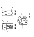
- FIG. 11 is an enlarged end view of a distal end of an anvil assembly including an alternative embodiment of an end cap according to the present disclosure
- FIG. 12 is an enlarged side view of the distal end of the anvil assembly of FIG. 11 ;
- FIG. 13 is an enlarged perspective view of the end cap of FIG. 11 .
- proximal will refer to the portion of the instrument closer to the operator and the term “distal” will refer to the portion of the instrument further from the operator.
- FIGS. 1-3 A prior art surgical stapling device 10 is shown in FIGS. 1-3 .
- stapling device 10 includes a stationary handle 14, a pivotable trigger 16, an elongated central body portion 18, a cartridge assembly 20 and an anvil assembly 22.
- Thumb buttons 24 are slidably positioned on each side of body 12 and are movable to manually advance an alignment pin 38 distally from cartridge assembly 20. (The pin 38 can alternately be automatically advanced upon actuation of trigger 16.)
- a release button 26 is positioned on the proximal portion of body 12 and is depressible to allow cartridge assembly 20 to return from an approximated position disposed adjacent to anvil assembly 22 to a position spaced from anvil assembly 22.
- anvil assembly 22 includes an anvil 36.
- Anvil 36 includes an opening 67 configured to receive alignment pin 38 therethrough during operation of stapling device 10.
- Anvil assembly 22 further includes a cap 39.
- Cap 39 provides anvil assembly 22 with a smooth surface which is less likely to snag tissue during use.
- opening 67 formed in anvil 36 includes a diameter slightly larger than the diameter of alignment pin 38.
- Alignment pin 38 may include a tapered or rounded distal free end 38a.
- the size and configuration of alignment pin 38 and opening 67 provides surgical stapling device 10 with a tolerance equal to approximately half of the width of alignment pin 38, or a distance "x". In this manner, alignment pin 38 may be laterally misaligned a distance of "x" before distal end 38a of alignment pin 38 will not be received within opening 67.
- "x" is equal to about 0.039 inches.
- surgical stapler 10 has been described to the extent necessary to disclose the aspects of the present disclosure. A more detailed discussion of the structure and function of a surgical stapler that is substantially similar to surgical stapler 10 is disclosed in commonly owned U.S. Patent No. 6,817,508 (the ⁇ 508 patent), the entire contents of which are incorporated by reference herein. Although described with reference to surgical stapling device 10, the aspects of present disclosure may be modified for use with other stapling devices having an advanceable alignment pin.
- End cap 51 may be composed of plastic, polymer or any other suitable material. End cap 51 defines a substantially D-shaped member configured to be received over an end of anvil assembly 22. End cap 51 may be frictionally secured to anvil assembly 22 or may instead be secured thereto using adhesives, mechanical fasteners or the like. It could also have a snap in feature or interlocking structure to engage an upper or side surface of the anvil assembly and optionally glued for additional holding. In some embodiments, end cap 51 is integrally (monolithically) formed with anvil assembly 22.
- end cap 51 is configured to be received on a pre-existing stapler; however, it is also envisioned that surgical staplers may be modified to incorporate the end cap. It is envisioned that the aspects of the present disclosure may be modified for use with any instrument including an alignment pin. As shown, end cap 51 is positioned above (in the orientation of FIG. 6 ) the rows of staple forming anvil depressions.
- end cap 51 defines an opening 53 configured to align with an opening formed in anvil 36 of stapler 10 when end cap 51 is securely received on anvil assembly 22.
- End cap 51 defines an alignment pin contact area 55 about opening 53 which provides a lead in feature.
- Alignment pin contact area 55 is configured to direct alignment pin 38 towards opening 53.
- the width of alignment pin contact area 55 is limited only by the width of end cap 51.
- Alignment pin contact area 55 in the illustrated embodiment includes a substantially V-shaped profile defining an angle ⁇ , ranging in one embodiment by way of example from about one-hundred fifty degrees (150°) to about one-hundred seventy degrees (170°), and preferably, in one embodiment, about one-hundred sixty degrees (160°).
- alignment pin contact area 55 includes a substantially U-shaped profile.
- An upper portion 55a of alignment pin contact area 55 also includes a curved or angled profile.
- Upper portion 55a of alignment pin contact area 55 is configured to further direct distal end 38a of alignment pin 38 towards opening 53 in end cap 51.
- alignment pin contact area 55 includes a coating, e.g., silicone, configured to reduce the friction between distal end 38a of alignment pin 38 and end cap 51 to facilitate sliding of alignment pin 38 against alignment pin contact area 55.
- End cap 51 includes a boss feature 57 configured for frictionally engaging and retaining alignment pin 38 upon receipt of distal end 38a of alignment pin 38 through opening 53.
- Boss feature 57 is configured to prevent premature retraction of alignment pin 38 during the actuation of stapler 10 by the interference fit provided by the ridges 59a, 59b.
- Boss feature 57 includes first and second boss members 57a, 57b extending inwardly about opening 53. Although shown including two boss members 57a, 57b, it is envisioned that end cap 51 may include one or more than two boss members.
- First and second boss members 57a, 57b each include a pin engagement surface 59a, 59b, respectively, configured to engage alignment pin 38 as distal end 38a of alignment pin 38 is received through opening 53.
- Pin engagement surfaces 59a, 59b may include a ridge, as shown, or may be otherwise configured to frictionally engage distal end 38a of alignment pin 38.
- Pin engagement surfaces 59a, 59b may include a coating, i.e., rubber (not shown), for more securely engaging alignment pin 38.
- alignment pin 38 may be advanced manually using thumb buttons such as button 24 of FIG. 1 .
- alignment pin 38 is automatically advanced during actuation of the device such as surgical stapling device 10 of FIG. 1 .
- Advancement of alignment pin 38 in the direction indicated by arrow "A”, directs the distal end 38a of alignment pin 38 toward opening 53 of end cap 51.
- pin contact area 55 if alignment pin 38 is out of alignment with opening 53 of cap 51, it will contact pin contact area 55.
- distal end 38a of alignment pin 38 with alignment pin contact area 55 causes the directing of alignment pin 38 towards opening 53 of end cap 51, in the direction indicated by arrow "B”.
- distal end 38a of alignment pin 38 is received within opening 53 of end cap 51.
- alignment pin 38 and end cap 51 provides surgical stapling device 10 with a tolerance equal to approximately half of the width of alignment pin contact area 55, or a distance "y". In this manner, alignment pin 38 may be laterally misaligned from opening 53 a distance of "y" before distal end 38a of alignment pin 38 will not be directed within opening 53. In one embodiment, "y" is equal to about 0.157 inches.
- boss feature 57 frictionally retains alignment pin 38 in the advanced position, thereby preventing premature retraction of alignment pin 38.
- Application of a sufficient proximal force will enable release from boss feature 57.
- End cap 151 is substantially similar to end cap 51, described hereinabove, and will therefore only be described as relates to the differences therebetween.
- End cap 151 is configured for secure engagement with an anvil assembly 122.
- End cap 151 has a spherical alignment pin contact area 155 with the curved surfaces directing the alignment pin 38 of FIGS. 8-9 toward opening 153.
- End cap 151 may be frictionally received on anvil assembly 122 or may instead be mechanically fastened, adhered, welded or otherwise secured thereto.
- End cap can alternatively be monolithically (integrally) formed with the anvil assembly.
- alignment pin contact area 155 directs an alignment pin (not shown) into opening 153 formed therein if the alignment pin is misaligned and contacts the contact area 155 in a similar manner as contact area 55.
- End cap 151 may include a boss feature (not shown) as in the embodiment of Fig. 7 .
Abstract
Description
- This application claims priority from provisional application serial no.
61/317,394, filed March 25, 2010 - The present disclosure relates generally to a surgical stapling apparatus and, more specifically, to a surgical stapling apparatus having a pin alignment assembly including lead-in and/or catch features.
- Surgical stapling instruments used for applying parallel rows of staples through compressed living tissue are well known in the art, and are commonly used, for example, for closure of tissue or organs prior to trans-section, prior to resection, or in anastomoses, and for occlusion of organs in thoracic and abdominal procedures.
- Typically, such surgical stapling instruments include an anvil assembly, a cartridge assembly for supporting an array of surgical staples, an approximation mechanism for approximating the anvil and cartridge assemblies, an alignment pin assembly for capturing tissue between the cartridge and anvil assemblies and for maintaining alignment between the cartridge and anvil assemblies during approximation and firing, and a firing mechanism for ejecting the surgical staples from the cartridge assembly. The approximation mechanism and the firing mechanism can include distinct actuators for effecting approximation and firing of the staples. An alignment pin assembly advances an alignment pin from the cartridge assembly into engagement with the anvil. The alignment pin assembly can be automatically actuated upon operation of the approximation mechanism and/or manually operated.
- Typically, the distal end of the alignment pin is received within an opening formed in the anvil assembly. The opening formed in the anvil assembly is typically sized slightly larger in diameter than the diameter of the alignment pin being received therein. This configuration prevents lateral movement of the alignment pin prior to and during firing of the surgical staples.
- It would be advantageous to provide an improved alignment pin assembly to expand manufacturing tolerances and accommodate for misalignment.
- In one aspect of the present disclosure, an alignment pin assembly is provided including an alignment pin configured to be advanced prior to actuation of a stapler and an end cap defining an opening configured to receive the alignment pin prior to actuation of the stapler. The end cap includes an alignment pin contact area formed about the opening configured to direct the alignment pin into the opening.
- The alignment pin contact area may define a substantially V-shaped or U-shaped profile. In some embodiments, the contact area can have curved surfaces. The alignment pin contact area may define in one embodiment an angle of about one-hundred fifty degrees to about one-hundred seventy degrees, and preferably in one embodiment an angle of about one-hundred sixty degrees. The end cap may be configured for reception on a distal end of an anvil assembly. Alternatively, the end cap may be integrally formed with an anvil assembly.
- In one embodiment, the end cap may include a boss feature on a distal side of the opening for frictionally engaging the alignment pin. The boss feature can include at least a first and second boss member. Each of the boss members may include an alignment pin engagement surface.
- Also provided in another aspect is a surgical stapler including a handle assembly, an elongated body extending from the handle assembly, a cartridge assembly mounted on the distal end of the elongated body and including an alignment pin configured for advancement from the cartridge assembly, and an anvil assembly positioned distal of the cartridge assembly. The anvil assembly includes an opening configured to receive the alignment pin, the opening including an angled alignment pin contacting area to provide a lead in configuration.
- In one embodiment, the alignment pin contact area defines a substantially V-shaped profile, while in another embodiment the alignment pin contact area defines a substantially U-shaped profile. The alignment pin contact area can define curved surfaces. The alignment pin contact area may define an angle of about one-hundred fifty degrees to about one-hundred seventy degrees, and preferably in one embodiment may define an angle of about one-hundred sixty degrees. The end cap may include a boss feature for frictionally engaging the alignment pin. The boss feature may include at least a first and second boss member. Each of the boss members may include an alignment pin engagement surface. The surgical stapler can have in some embodiments a tolerance equal to approximately half the width of the contact area, thereby enabling the alignment pin to be directed within the opening if a lateral misalignment from the opening is less than or equal to a distance measuring up to approximately half the width of the contact area.
- Embodiments of the presently disclosed surgical stapling apparatus are described herein with reference to the drawings, wherein:
-
FIG. 1 is a perspective view of a prior art surgical stapling device; -
FIG. 2 is an enlarged perspective view of the distal end of the prior art surgical stapling device ofFIG. 1 ; -
FIG. 3 is an enlarged perspective view of a portion of the anvil assembly of the prior art surgical stapling device ofFIG. 1 ; -
FIG. 4 is a cross-sectional schematic view of the anvil assembly and alignment pin of the prior art surgical stapling device ofFIG. 1 ; -
FIG. 5 is an enlarged perspective view of the distal end of the surgical stapling device ofFIG. 1 including an end cap according to an embodiment of the present disclosure; -
FIG. 6 is an enlarged perspective view ofdetail 6 ofFIG. 5 ; -
FIG. 7 is a cross-sectional end view taken along line 7-7 ofFIG. 6 -
FIG. 8 is an enlarged end view ofdetail 6 ofFIG. 5 with the alignment pin in the retracted position and not shown; -
FIG. 9 is a cross-sectional view of the end cap and alignment pin ofFIG. 5 prior to engagement of the alignment pin with the end cap; -
FIG. 10 is a cross-sectional view of the end cap and alignment pin ofFIG. 5 upon engagement of the alignment pin with the end cap; -
FIG. 11 is an enlarged end view of a distal end of an anvil assembly including an alternative embodiment of an end cap according to the present disclosure; -
FIG. 12 is an enlarged side view of the distal end of the anvil assembly ofFIG. 11 ; and -
FIG. 13 is an enlarged perspective view of the end cap ofFIG. 11 . - Embodiments of the presently disclosed alignment pin assembly will now be described in detail with reference to the drawings, wherein like reference numerals designate corresponding elements in each of the several views. Throughout this description, the term "proximal" will refer to the portion of the instrument closer to the operator and the term "distal" will refer to the portion of the instrument further from the operator.
- A prior art
surgical stapling device 10 is shown inFIGS. 1-3 . Briefly,stapling device 10 includes astationary handle 14, apivotable trigger 16, an elongatedcentral body portion 18, acartridge assembly 20 and ananvil assembly 22.Thumb buttons 24 are slidably positioned on each side ofbody 12 and are movable to manually advance analignment pin 38 distally fromcartridge assembly 20. (Thepin 38 can alternately be automatically advanced upon actuation oftrigger 16.) Arelease button 26 is positioned on the proximal portion ofbody 12 and is depressible to allowcartridge assembly 20 to return from an approximated position disposed adjacent toanvil assembly 22 to a position spaced fromanvil assembly 22. - With particular reference to
FIG. 2 and3 ,anvil assembly 22 includes ananvil 36. Anvil 36 includes anopening 67 configured to receivealignment pin 38 therethrough during operation ofstapling device 10. Anvilassembly 22 further includes acap 39.Cap 39 providesanvil assembly 22 with a smooth surface which is less likely to snag tissue during use. - Turning now to
FIG. 4 , opening 67 formed inanvil 36 includes a diameter slightly larger than the diameter ofalignment pin 38.Alignment pin 38 may include a tapered or rounded distalfree end 38a. As depicted inFIG. 4 , the size and configuration ofalignment pin 38 andopening 67 providessurgical stapling device 10 with a tolerance equal to approximately half of the width ofalignment pin 38, or a distance "x". In this manner,alignment pin 38 may be laterally misaligned a distance of "x" beforedistal end 38a ofalignment pin 38 will not be received withinopening 67. In one embodiment, "x" is equal to about 0.039 inches. - The structure and function of
surgical stapler 10 has been described to the extent necessary to disclose the aspects of the present disclosure. A more detailed discussion of the structure and function of a surgical stapler that is substantially similar tosurgical stapler 10 is disclosed in commonly ownedU.S. Patent No. 6,817,508 (the `508 patent), the entire contents of which are incorporated by reference herein. Although described with reference tosurgical stapling device 10, the aspects of present disclosure may be modified for use with other stapling devices having an advanceable alignment pin. - With reference now to
FIGS. 5-7 , an embodiment of an end cap according to the present disclosure is shown generally asend cap 51.End cap 51 may be composed of plastic, polymer or any other suitable material.End cap 51 defines a substantially D-shaped member configured to be received over an end ofanvil assembly 22.End cap 51 may be frictionally secured toanvil assembly 22 or may instead be secured thereto using adhesives, mechanical fasteners or the like. It could also have a snap in feature or interlocking structure to engage an upper or side surface of the anvil assembly and optionally glued for additional holding. In some embodiments,end cap 51 is integrally (monolithically) formed withanvil assembly 22. As shown,end cap 51 is configured to be received on a pre-existing stapler; however, it is also envisioned that surgical staplers may be modified to incorporate the end cap. It is envisioned that the aspects of the present disclosure may be modified for use with any instrument including an alignment pin. As shown,end cap 51 is positioned above (in the orientation ofFIG. 6 ) the rows of staple forming anvil depressions. - With reference to
FIGS. 8-10 ,end cap 51 defines anopening 53 configured to align with an opening formed inanvil 36 ofstapler 10 whenend cap 51 is securely received onanvil assembly 22.End cap 51 defines an alignmentpin contact area 55 about opening 53 which provides a lead in feature. Alignmentpin contact area 55 is configured to directalignment pin 38 towardsopening 53. The width of alignmentpin contact area 55 is limited only by the width ofend cap 51. Alignmentpin contact area 55 in the illustrated embodiment includes a substantially V-shaped profile defining an angle α, ranging in one embodiment by way of example from about one-hundred fifty degrees (150°) to about one-hundred seventy degrees (170°), and preferably, in one embodiment, about one-hundred sixty degrees (160°). In an alternate embodiment, alignmentpin contact area 55 includes a substantially U-shaped profile. Anupper portion 55a of alignmentpin contact area 55 also includes a curved or angled profile.Upper portion 55a of alignmentpin contact area 55 is configured to further directdistal end 38a ofalignment pin 38 towards opening 53 inend cap 51. In one embodiment, alignmentpin contact area 55 includes a coating, e.g., silicone, configured to reduce the friction betweendistal end 38a ofalignment pin 38 andend cap 51 to facilitate sliding ofalignment pin 38 against alignmentpin contact area 55. - With particular reference now to
FIG. 7 , the alignment pin catch feature is illustrated.End cap 51 includes aboss feature 57 configured for frictionally engaging and retainingalignment pin 38 upon receipt ofdistal end 38a ofalignment pin 38 throughopening 53.Boss feature 57 is configured to prevent premature retraction ofalignment pin 38 during the actuation ofstapler 10 by the interference fit provided by theridges Boss feature 57 includes first andsecond boss members boss members end cap 51 may include one or more than two boss members. First andsecond boss members pin engagement surface alignment pin 38 asdistal end 38a ofalignment pin 38 is received throughopening 53.Pin engagement surfaces distal end 38a ofalignment pin 38.Pin engagement surfaces alignment pin 38. - The operation of
alignment end cap 51 will be described with particular reference toFIGS. 9 and 10 . As noted above,alignment pin 38 may be advanced manually using thumb buttons such asbutton 24 ofFIG. 1 . Alternatively,alignment pin 38 is automatically advanced during actuation of the device such assurgical stapling device 10 ofFIG. 1 . Advancement ofalignment pin 38, in the direction indicated by arrow "A", directs thedistal end 38a ofalignment pin 38 toward opening 53 ofend cap 51. However, during advancement ofalignment pin 38, ifalignment pin 38 is out of alignment with opening 53 ofcap 51, it will contactpin contact area 55. Engagement ofdistal end 38a ofalignment pin 38 with alignmentpin contact area 55 causes the directing ofalignment pin 38 towards opening 53 ofend cap 51, in the direction indicated by arrow "B". Upon complete advancement ofalignment pin 38, in the direction indicated by arrow "C",distal end 38a ofalignment pin 38 is received within opening 53 ofend cap 51. - As depicted in
FIGS. 9 and 10 , the size and configuration ofalignment pin 38 andend cap 51 providessurgical stapling device 10 with a tolerance equal to approximately half of the width of alignmentpin contact area 55, or a distance "y". In this manner,alignment pin 38 may be laterally misaligned from opening 53 a distance of "y" beforedistal end 38a ofalignment pin 38 will not be directed withinopening 53. In one embodiment, "y" is equal to about 0.157 inches. - Each of
pin engagement surfaces second boss members boss feature 57 engagedistal end 38a ofalignment pin 38 asalignment pin 38 is received throughopening 53. In this manner,boss feature 57 frictionally retainsalignment pin 38 in the advanced position, thereby preventing premature retraction ofalignment pin 38. Application of a sufficient proximal force will enable release fromboss feature 57. - With reference now to
FIGS. 11-13 , an alternate embodiment of an end cap according to the present disclosure is shown generally asend cap 151.End cap 151 is substantially similar to endcap 51, described hereinabove, and will therefore only be described as relates to the differences therebetween.End cap 151 is configured for secure engagement with ananvil assembly 122.End cap 151 has a spherical alignmentpin contact area 155 with the curved surfaces directing thealignment pin 38 ofFIGS. 8-9 towardopening 153.End cap 151 may be frictionally received onanvil assembly 122 or may instead be mechanically fastened, adhered, welded or otherwise secured thereto. End cap can alternatively be monolithically (integrally) formed with the anvil assembly. In use, alignmentpin contact area 155 directs an alignment pin (not shown) intoopening 153 formed therein if the alignment pin is misaligned and contacts thecontact area 155 in a similar manner ascontact area 55.End cap 151 may include a boss feature (not shown) as in the embodiment ofFig. 7 . - It will be understood that various modifications may be made to the embodiments disclosed herein. For example, the components of the alignment pin assembly may be modified for use with other instruments including an alignment pin. Therefore, the above description should not be construed as limiting, but merely as exemplifications of preferred embodiments. Those skilled in the art will envision other modifications within the scope and spirit of the claims appended hereto.
- The invention may be described by reference to the following numbered paragraphs:
- 1. An alignment pin assembly for a surgical stapler comprising:
- an alignment pin configured to be advanced prior to actuation of a stapler; and
- an end cap defining an opening configured to receive the alignment pin prior to actuation of the stapler, wherein the end cap includes an alignment pin contact area formed about the opening configured to direct the alignment pin into the opening.
- 2. The alignment pin assembly of paragraph 1, wherein the alignment pin contact area defines a substantially V-shaped profile.
- 3. The alignment pin assembly of paragraph 1, wherein the alignment pin contact area defines curved surfaces.
- 4. The alignment pin assembly of paragraph 1, wherein the alignment pin contact area defines an angle of about one-hundred fifty degrees to about one-hundred seventy degrees.
- 5. The alignment pin assembly of paragraph 1, wherein the end cap is mounted to the anvil assembly.
- 6. The alignment pin assembly of claim 1, wherein the alignment pin is manually advanced.
- 7. The alignment pin assembly of claim 1, wherein the end cap is integrally formed with an anvil assembly.
- 8. The alignment pin assembly of paragraph 1, wherein the end cap includes a boss feature for frictionally engaging the alignment pin.
- 9. The alignment pin assembly of paragraph 8, wherein the boss feature includes at least a first and second boss member in each of the boss members includes an alignment pin engagement surface.
- 10. A surgical stapler comprising:
- a handle assembly;
- an elongated body extending from the handle assembly;
- a cartridge assembly mounted on the distal end of the elongated body and including an alignment pin, the alignment pin being configured for advancement from the cartridge assembly; and
- an anvil assembly positioned distal of the cartridge assembly and having an opening configured to receive the alignment pin, the opening including an alignment pin contact area to provide a lead in configuration to direct the alignment pin within the opening.
- 11. The surgical stapler of
paragraph 10, wherein the alignment pin contact area defines a substantially V-shaped profile. - 12. The surgical stapler of paragraph 11, wherein the alignment pin contact area is angled.
- 13. The surgical stapler of
paragraph 10, wherein the alignment pin contact area defines a curved profile. - 14. The surgical stapler of
paragraph 10, wherein the alignment pin contact area defines an angle of about one-hundred fifty degrees to about one-hundred seventy degrees. - 15. The alignment pin assembly of
paragraph 10, wherein the anvil assembly includes a retaining feature on a distal side of the opening, the retaining feature frictionally engaging the alignment pin. - 16. The alignment pin assembly of paragraph 15, wherein the retaining feature includes ridges.
- 17. The alignment pin assembly of
paragraph 10, wherein the opening is formed on an end cap of the anvil assembly. - 18. The alignment pin assembly of
paragraph 10, wherein the opening is spaced from anvil depressions of the anvil assembly. - 19. The alignment pin assembly of paragraph 17, wherein the alignment pin contact area has a width and the surgical staple has a tolerance equal to approximately half the width, thereby enabling the alignment pin to be directed within the opening if a lateral misalignment from the opening is less than or equal to a distance measuring up to approximately half the width of the pin contact area.
Claims (14)
- A surgical stapler comprising:a handle assembly;an elongated body extending from the handle assembly;a cartridge assembly mounted on the distal end of the elongated body and including an alignment pin, the alignment pin being configured for advancement from the cartridge assembly; andan anvil assembly positioned distal of the cartridge assembly and having an opening configured to receive the alignment pin, the opening including an alignment pin contact area to provide a lead in configuration to direct the alignment pin within the opening.
- The surgical stapler of claim 1, wherein the alignment pin contact area defines a substantially V-shaped profile.
- The surgical stapler of claim 1, wherein the alignment pin contact area is angled.
- The surgical stapler of claim 1, wherein the alignment pin contact area defines a curved profile.
- The surgical stapler of any of claims 1-4, wherein the alignment pin contact area defines an angle of about one-hundred fifty degrees to about one-hundred seventy degrees.
- The alignment pin assembly of any of claims 1-5, wherein the anvil assembly includes a retaining feature on a distal side of the opening, the retaining feature frictionally engaging the alignment pin.
- The alignment pin assembly of claim 6, wherein the retaining feature includes ridges.
- The alignment pin assembly of any of claims 1-7, further comprising an end cap mounted to the anvil assembly, wherein the opening is formed on the end cap of the anvil assembly.
- The alignment pin assembly of any of claims 1-8, wherein the opening is spaced from anvil depressions of the anvil assembly.
- The alignment pin assembly of any of claims 1-9, wherein the alignment pin contact area has a width and the surgical staple has a tolerance equal to approximately half the width, thereby enabling the alignment pin to be directed within the opening if a lateral misalignment from the opening is less than or equal to a distance measuring up to approximately half the width of the pin contact area.
- The alignment pin assembly of any of claims 1-10, wherein the alignment pin is manually advanced.
- The alignment pin assembly of claim 8, wherein the end cap is integrally formed with an anvil assembly.
- The alignment pin assembly of claims 8 or 12, wherein the end cap includes a boss feature for frictionally engaging the alignment pin.
- The alignment pin assembly of claim 13, wherein the boss feature includes at least a first and second boss member and each of the boss members includes an alignment pin engagement surface.
Applications Claiming Priority (2)
| Application Number | Priority Date | Filing Date | Title |
|---|---|---|---|
| US31739410P | 2010-03-25 | 2010-03-25 | |
| US13/028,608 US8827137B2 (en) | 2010-03-25 | 2011-02-16 | Pin alignment assembly for surgical stapler |
Publications (2)
| Publication Number | Publication Date |
|---|---|
| EP2368503A1 true EP2368503A1 (en) | 2011-09-28 |
| EP2368503B1 EP2368503B1 (en) | 2018-02-21 |
Family
ID=44061312
Family Applications (1)
| Application Number | Title | Priority Date | Filing Date |
|---|---|---|---|
| EP11250371.9A Not-in-force EP2368503B1 (en) | 2010-03-25 | 2011-03-24 | Pin alignment assembly for surgical stapler |
Country Status (6)
| Country | Link |
|---|---|
| US (2) | US8827137B2 (en) |
| EP (1) | EP2368503B1 (en) |
| JP (1) | JP5808925B2 (en) |
| CN (2) | CN104856736B (en) |
| AU (2) | AU2011200918B2 (en) |
| CA (1) | CA2733215C (en) |
Families Citing this family (12)
| Publication number | Priority date | Publication date | Assignee | Title |
|---|---|---|---|---|
| KR101851727B1 (en) * | 2011-12-16 | 2018-06-12 | 에스케이하이닉스 주식회사 | Semiconductor device and method for manufacturing the same |
| CN102755178B (en) * | 2012-07-19 | 2014-11-26 | 浙江海圣医疗器械有限公司 | Linear type automatic anastomat |
| US10952730B2 (en) * | 2015-10-15 | 2021-03-23 | Ethicon Llc | End effector for surgical stapler with varying curve and taper |
| US10258334B2 (en) | 2015-12-31 | 2019-04-16 | Ethicon Llc | Surgical stapler with variable height drivers for uniform staple formation |
| US10045780B2 (en) * | 2015-12-31 | 2018-08-14 | Ethicon Llc | Method of applying staples in lower anterior bowel resection |
| US10575848B2 (en) | 2015-12-31 | 2020-03-03 | Ethicon Llc | Surgical stapler with fixed jaw support pin |
| CN106923874B (en) * | 2015-12-31 | 2020-04-28 | 天臣国际医疗科技股份有限公司 | Operation anastomat |
| US10709448B2 (en) * | 2017-06-05 | 2020-07-14 | Grena Usa Llc | Linear cutter stapler |
| CN114206227A (en) * | 2019-08-02 | 2022-03-18 | 柯惠有限合伙公司 | Surgical stapling device with bending tool assembly |
| RU196000U1 (en) * | 2019-09-26 | 2020-02-12 | Сергей Владимирович Журин | UNIVERSAL BINDING LINEAR MACHINE |
| US11744584B2 (en) * | 2020-06-09 | 2023-09-05 | Covidien Lp | Alignment pin assembly for surgical stapler |
| WO2023230966A1 (en) * | 2022-06-01 | 2023-12-07 | Covidien Lp | Anvil assembly for surgical stapling device |
Citations (5)
| Publication number | Priority date | Publication date | Assignee | Title |
|---|---|---|---|---|
| US3494533A (en) * | 1966-10-10 | 1970-02-10 | United States Surgical Corp | Surgical stapler for stitching body organs |
| US5732871A (en) * | 1993-12-06 | 1998-03-31 | Ethicon, Inc. | Surgical stapling instrument with articulated stapling head assembly on rotatable and flexible support shaft |
| US5772099A (en) * | 1996-04-01 | 1998-06-30 | United States Surgical Corporation | Surgical fastening apparatus with alignment pin |
| US6817508B1 (en) | 2000-10-13 | 2004-11-16 | Tyco Healthcare Group, Lp | Surgical stapling device |
| US20070262116A1 (en) * | 2005-08-31 | 2007-11-15 | Hueil Joseph C | Surgical stapling device with multiple stacked actuator wedge cams for driving staple drivers |
Family Cites Families (143)
| Publication number | Priority date | Publication date | Assignee | Title |
|---|---|---|---|---|
| US2891250A (en) * | 1956-10-15 | 1959-06-23 | Hirata Yasuhiro | Bronchus seaming instrument |
| US3080564A (en) * | 1959-09-10 | 1963-03-12 | Strekopitov Alexey Alexeevich | Instrument for stitching hollow organs |
| US3252643A (en) * | 1962-12-24 | 1966-05-24 | Strekopytov Alexey Alexcevich | Instrument for suturing living tissue |
| US3269630A (en) * | 1964-04-30 | 1966-08-30 | Fleischer Harry | Stapling instrument |
| US3275211A (en) | 1965-05-10 | 1966-09-27 | United States Surgical Corp | Surgical stapler with replaceable cartridge |
| US3315863A (en) * | 1965-07-06 | 1967-04-25 | United States Surgical Corp | Medical instrument |
| DE1791114B1 (en) * | 1967-09-19 | 1971-12-02 | Vnii Chirurgitscheskoj Apparat | Surgical device for stapling tissues |
| BE758685A (en) | 1970-10-14 | 1971-05-10 | Vnii Khirurgicheskoi Apparatur | SURGICAL APPARATUS FOR TISSUE SUTURE WITH STAPLES |
| CH550578A (en) * | 1971-05-03 | 1974-06-28 | Vnii Khirurgicheskoi Apparatur | SURGICAL SEWING DEVICE FOR SEWING TISSUE AND ORGANS WITH THE HELP OF METAL CLIPS. |
| US3822818A (en) * | 1973-02-20 | 1974-07-09 | A Strekopytov | Surgical instrument for joining osseous tissues by staples |
| SU506963A1 (en) * | 1973-07-26 | 1976-08-25 | Всесоюзный Научно-Исследовательский И Испытательный Институт Медицинской Техники Министерства Здравоохранения Ссср | Surgical stapler |
| SU449524A1 (en) | 1973-07-31 | 1976-05-15 | Всесоюзный научно-исследовательский и испытательный институт медицинской техники | Surgical apparatus for cross-linking of organs |
| US3935961A (en) * | 1974-09-30 | 1976-02-03 | Bennett Robert A | Unitary beverage container |
| US4047654A (en) | 1976-06-23 | 1977-09-13 | Alfredo Alvarado | Surgical stapler |
| SU1036324A1 (en) * | 1978-03-31 | 1983-08-23 | Всесоюзный научно-исследовательский и испытательный институт медицинской техники | Surgical suturing device |
| US4216891A (en) * | 1979-02-12 | 1980-08-12 | Behlke Harold O | Surgical stapler |
| SU886900A1 (en) | 1979-03-26 | 1981-12-07 | Всесоюзный научно-исследовательский и испытательный институт медицинской техники | Surgical apparatus for applying line sutures |
| US4273281A (en) * | 1979-07-23 | 1981-06-16 | Franklin G. Smith | Internal surgical stapler |
| US4272002A (en) * | 1979-07-23 | 1981-06-09 | Lawrence M. Smith | Internal surgical stapler |
| SU942719A1 (en) | 1979-11-23 | 1982-07-15 | Всесоюзный научно-исследовательский и испытательный институт медицинской техники | Surgical suturing apparatus for application of linear sutures |
| US4485811A (en) | 1980-02-08 | 1984-12-04 | Vsesojuzny Nauchny Tsentr Khirurgii | Resection apparatus |
| US4296881A (en) | 1980-04-03 | 1981-10-27 | Sukoo Lee | Surgical stapler using cartridge |
| US4378901A (en) * | 1980-05-22 | 1983-04-05 | Akopov Ernest M | Apparatus for applying a staple suture |
| US4354628A (en) | 1980-09-29 | 1982-10-19 | United States Surgical Corporation | Surgical stapler apparatus having pivotally related staple holder and anvil |
| US4402444A (en) | 1981-04-20 | 1983-09-06 | United States Surgical Corporation | Surgical stapling instrument with automatic frame reinforcement |
| US4383634A (en) * | 1981-05-26 | 1983-05-17 | United States Surgical Corporation | Surgical stapler apparatus with pivotally mounted actuator assemblies |
| US4475679A (en) | 1981-08-07 | 1984-10-09 | Fleury Jr George J | Multi-staple cartridge for surgical staplers |
| US4632290A (en) | 1981-08-17 | 1986-12-30 | United States Surgical Corporation | Surgical stapler apparatus |
| US4415112A (en) | 1981-10-27 | 1983-11-15 | United States Surgical Corporation | Surgical stapling assembly having resiliently mounted anvil |
| US4442964A (en) * | 1981-12-07 | 1984-04-17 | Senco Products, Inc. | Pressure sensitive and working-gap controlled surgical stapling instrument |
| US4470533A (en) | 1982-08-13 | 1984-09-11 | Ethicon, Inc. | Surgical instrument for suturing tissues and organs |
| US4506671A (en) * | 1983-03-30 | 1985-03-26 | United States Surgical Corporation | Apparatus for applying two-part surgical fasteners |
| US4506670A (en) * | 1983-03-30 | 1985-03-26 | United States Surgical Corporation | Two-part surgical fastener applying apparatus with frangible member |
| US4522327A (en) * | 1983-05-18 | 1985-06-11 | United States Surgical Corporation | Surgical fastener applying apparatus |
| US4527724A (en) * | 1983-06-10 | 1985-07-09 | Senmed, Inc. | Disposable linear surgical stapling instrument |
| USD273513S (en) * | 1983-06-10 | 1984-04-17 | Senco Products, Inc. | Linear surgical stapling instrument |
| US4602634A (en) * | 1983-09-23 | 1986-07-29 | Ethicon, Inc. | Method and instrument for applying a fastener to a tissue using means to grasp, guide and pull the fastener through the tissue |
| US4568009A (en) * | 1984-01-20 | 1986-02-04 | United States Surgical Corporation | Surgical fastener applying apparatus |
| US4530453A (en) * | 1983-10-04 | 1985-07-23 | United States Surgical Corporation | Surgical fastener applying apparatus |
| US4508253A (en) * | 1983-10-04 | 1985-04-02 | United States Surgical Corporation | Surgical fastener applying apparatus |
| US4550870A (en) | 1983-10-13 | 1985-11-05 | Alchemia Ltd. Partnership | Stapling device |
| US4612933A (en) | 1984-03-30 | 1986-09-23 | Senmed, Inc. | Multiple-load cartridge assembly for a linear surgical stapling instrument |
| US4606345A (en) * | 1984-07-16 | 1986-08-19 | Ethicon, Inc. | Surgical instrument for applying two-piece fasteners comprising U-shaped staples and frictionally held receivers (Case II) |
| US4607636A (en) * | 1984-07-16 | 1986-08-26 | Ethicon, Inc. | Surgical instrument for applying fasteners having tissue locking means for maintaining the tissue in the instrument while applying the fasteners (case I) |
| US4606344A (en) * | 1984-07-16 | 1986-08-19 | Ethicon, Inc. | Surgical instrument for applying fasteners having improved gap indicating means (Case V) |
| US4605004A (en) * | 1984-07-16 | 1986-08-12 | Ethicon, Inc. | Surgical instrument for applying fasteners said instrument including force supporting means (case IV) |
| US4585153A (en) * | 1984-07-16 | 1986-04-29 | Ethicon, Inc. | Surgical instrument for applying two-piece fasteners comprising frictionally held U-shaped staples and receivers (Case III) |
| US4589582A (en) * | 1984-08-23 | 1986-05-20 | Senmed, Inc. | Cartridge and driver assembly for a surgical stapling instrument |
| US4617928A (en) | 1984-09-17 | 1986-10-21 | Alfranca Jose Maria P | Surgical instrument for practicing mechanical sutures and biopsies |
| US4573622A (en) * | 1984-10-19 | 1986-03-04 | United States Surgical Corporation | Surgical fastener applying apparatus with variable fastener arrays |
| US4767044A (en) * | 1984-10-19 | 1988-08-30 | United States Surgical Corporation | Surgical fastener applying apparatus |
| US4566620A (en) * | 1984-10-19 | 1986-01-28 | United States Surgical Corporation | Articulated surgical fastener applying apparatus |
| US4580712A (en) * | 1984-10-19 | 1986-04-08 | United States Surgical Corporation | Surgical fastener applying apparatus with progressive application of fastener |
| US4605001A (en) * | 1984-10-19 | 1986-08-12 | Senmed, Inc. | Surgical stapling instrument with dual staple height mechanism |
| JPS61127582U (en) * | 1985-01-30 | 1986-08-11 | ||
| US4665916A (en) * | 1985-08-09 | 1987-05-19 | United States Surgical Corporation | Surgical stapler apparatus |
| US4728020A (en) | 1985-08-30 | 1988-03-01 | United States Surgical Corporation | Articulated surgical fastener applying apparatus |
| CH670753A5 (en) * | 1985-09-10 | 1989-07-14 | Vnii Ispytatel Med Tech | |
| US4715520A (en) | 1985-10-10 | 1987-12-29 | United States Surgical Corporation | Surgical fastener applying apparatus with tissue edge control |
| US4802614A (en) * | 1986-05-23 | 1989-02-07 | United States Surgical Corporation | Surgical stapling instrument and cartridge |
| US4714187A (en) | 1986-11-26 | 1987-12-22 | United States Surgical Corporation | Reloading unit for surgical fastening instruments |
| US4941623A (en) * | 1987-05-12 | 1990-07-17 | United States Surgical Corporation | Stapling process and device for use on the mesentery of the abdomen |
| US4848637A (en) * | 1987-06-11 | 1989-07-18 | Pruitt J Crayton | Staple device for use on the mesenteries of the abdomen |
| US4930503A (en) * | 1987-06-11 | 1990-06-05 | Pruitt J Crayton | Stapling process and device for use on the mesenteries of the abdomen |
| US4819853A (en) * | 1987-12-31 | 1989-04-11 | United States Surgical Corporation | Surgical fastener cartridge |
| GB8800909D0 (en) * | 1988-01-15 | 1988-02-17 | Ethicon Inc | Gas powered surgical stapler |
| US4805823A (en) * | 1988-03-18 | 1989-02-21 | Ethicon, Inc. | Pocket configuration for internal organ staplers |
| US5071052A (en) * | 1988-09-22 | 1991-12-10 | United States Surgical Corporation | Surgical fastening apparatus with activation lockout |
| US4881545A (en) | 1988-12-08 | 1989-11-21 | United States Surgical Corporation | Surgical fastener cartridge with improved body tissue cutting knife assembly |
| US4915100A (en) * | 1988-12-19 | 1990-04-10 | United States Surgical Corporation | Surgical stapler apparatus with tissue shield |
| US5100042A (en) | 1990-03-05 | 1992-03-31 | United States Surgical Corporation | Surgical fastener apparatus |
| US5005754A (en) * | 1990-04-04 | 1991-04-09 | Ethicon, Inc. | Bladder and mandrel for use with surgical stapler |
| US5116349A (en) * | 1990-05-23 | 1992-05-26 | United States Surgical Corporation | Surgical fastener apparatus |
| CA2052176A1 (en) * | 1990-10-05 | 1992-04-06 | Daniel P. Rodak | Controlled closure mechanism |
| JP2550813Y2 (en) * | 1990-10-19 | 1997-10-15 | 株式会社大林組 | Column member connection structure |
| CA2055943C (en) | 1990-12-06 | 2003-09-23 | Daniel P. Rodak | Surgical fastening apparatus with locking mechanism |
| US5470009A (en) | 1990-12-06 | 1995-11-28 | United States Surgical Corporation | Surgical fastening apparatus with locking mechanism |
| US5219111A (en) * | 1991-03-11 | 1993-06-15 | Ethicon, Inc. | Pneumatically actuated linear stapling device |
| US5172845A (en) | 1991-04-12 | 1992-12-22 | Tejeiro William V | Right angle articulated intestinal stapler |
| AU671685B2 (en) | 1991-05-14 | 1996-09-05 | United States Surgical Corporation | Surgical stapler with spent cartridge sensing and lockout means |
| US5413267A (en) * | 1991-05-14 | 1995-05-09 | United States Surgical Corporation | Surgical stapler with spent cartridge sensing and lockout means |
| US5137198A (en) | 1991-05-16 | 1992-08-11 | Ethicon, Inc. | Fast closure device for linear surgical stapling instrument |
| US5579978A (en) | 1991-10-18 | 1996-12-03 | United States Surgical Corporation | Apparatus for applying surgical fasteners |
| CA2078794C (en) | 1991-10-18 | 1998-10-06 | Frank J. Viola | Locking device for an apparatus for applying surgical fasteners |
| DE69217808T2 (en) * | 1991-10-18 | 1997-07-24 | United States Surgical Corp | Device for attaching surgical fasteners |
| AU660712B2 (en) * | 1991-10-18 | 1995-07-06 | United States Surgical Corporation | Apparatus for applying surgical fasteners |
| US5240163A (en) | 1991-10-30 | 1993-08-31 | American Cyanamid Company | Linear surgical stapling instrument |
| US5368599A (en) | 1992-10-08 | 1994-11-29 | United States Surgical Corporation | Surgical fastening apparatus with suture array |
| US5503320A (en) * | 1993-08-19 | 1996-04-02 | United States Surgical Corporation | Surgical apparatus with indicator |
| US5542594A (en) * | 1993-10-06 | 1996-08-06 | United States Surgical Corporation | Surgical stapling apparatus with biocompatible surgical fabric |
| US5439155A (en) * | 1993-10-07 | 1995-08-08 | United States Surgical Corporation | Cartridge for surgical fastener applying apparatus |
| US5405073A (en) * | 1993-12-06 | 1995-04-11 | Ethicon, Inc. | Flexible support shaft assembly |
| US5470008A (en) | 1993-12-20 | 1995-11-28 | United States Surgical Corporation | Apparatus for applying surgical fasteners |
| US5452836A (en) | 1994-02-07 | 1995-09-26 | Ethicon Endo-Surgery, Inc. | Surgical stapling instrument with improved jaw closure and staple firing actuator mechanism |
| WO1995023557A1 (en) * | 1994-03-01 | 1995-09-08 | United States Surgical Corporation | Surgical stapler with anvil sensor and lockout |
| CA2145723A1 (en) | 1994-03-30 | 1995-10-01 | Steven W. Hamblin | Surgical stapling instrument with remotely articulated stapling head assembly on rotatable support shaft |
| US5735445A (en) * | 1995-03-07 | 1998-04-07 | United States Surgical Corporation | Surgical stapler |
| US5678748A (en) | 1995-05-24 | 1997-10-21 | Vir Engineering | Surgical stapler with improved safety mechanism |
| US5641111A (en) * | 1995-06-28 | 1997-06-24 | Ethicon Endo-Surgery, Inc. | Surgical stapling instrument with anvil cutting guide |
| US5706998A (en) * | 1995-07-17 | 1998-01-13 | United States Surgical Corporation | Surgical stapler with alignment pin locking mechanism |
| US5605272A (en) * | 1996-03-12 | 1997-02-25 | Ethicon Endo-Surgery, Inc. | Trigger mechanism for surgical instruments |
| US5697543A (en) | 1996-03-12 | 1997-12-16 | Ethicon Endo-Surgery, Inc. | Linear stapler with improved firing stroke |
| US5810240A (en) | 1996-03-15 | 1998-09-22 | United States Surgical Corporation | Surgical fastener applying device |
| US6231565B1 (en) * | 1997-06-18 | 2001-05-15 | United States Surgical Corporation | Robotic arm DLUs for performing surgical tasks |
| US6805273B2 (en) * | 2002-11-04 | 2004-10-19 | Federico Bilotti | Surgical stapling instrument |
| US7407076B2 (en) * | 2000-10-13 | 2008-08-05 | Tyco Healthcare Group Lp | Surgical stapling device |
| US6638285B2 (en) | 2001-04-16 | 2003-10-28 | Shlomo Gabbay | Biological tissue strip and system and method to seal tissue |
| US6470541B1 (en) * | 2001-04-17 | 2002-10-29 | Louis L. Lerner | Fabric anchor |
| AU2003226050A1 (en) * | 2002-04-11 | 2003-10-27 | Tyco Healthcare Group, Lp | Surgical stapling apparatus including an anvil and cartridge each having cooperating mating surfaces |
| AU2003277294A1 (en) | 2002-10-04 | 2004-05-04 | Tyco Healthcare Group, Lp | Angled surgical fastener apparatus |
| US7147140B2 (en) | 2003-12-30 | 2006-12-12 | Ethicon Endo - Surgery, Inc. | Cartridge retainer for a curved cutter stapler |
| US7549563B2 (en) * | 2003-12-30 | 2009-06-23 | Ethicon Endo-Surgery, Inc. | Rotating curved cutter stapler |
| US7134587B2 (en) | 2003-12-30 | 2006-11-14 | Ethicon Endo-Surgery, Inc. | Knife retraction arm for a curved cutter stapler |
| US7207472B2 (en) * | 2003-12-30 | 2007-04-24 | Ethicon Endo-Surgery, Inc. | Cartridge with locking knife for a curved cutter stapler |
| US7147139B2 (en) | 2003-12-30 | 2006-12-12 | Ethicon Endo-Surgery, Inc | Closure plate lockout for a curved cutter stapler |
| US6988650B2 (en) * | 2003-12-30 | 2006-01-24 | Ethicon Endo-Surgery, Inc. | Retaining pin lever advancement mechanism for a curved cutter stapler |
| US7766207B2 (en) * | 2003-12-30 | 2010-08-03 | Ethicon Endo-Surgery, Inc. | Articulating curved cutter stapler |
| US20050143759A1 (en) | 2003-12-30 | 2005-06-30 | Kelly William D. | Curved cutter stapler shaped for male pelvis |
| US7204404B2 (en) * | 2003-12-30 | 2007-04-17 | Ethicon Endo-Surgery, Inc. | Slotted pins guiding knife in a curved cutter stapler |
| US7210609B2 (en) * | 2004-07-30 | 2007-05-01 | Tools For Surgery, Llc | Stapling apparatus having a curved anvil and driver |
| JP4607184B2 (en) * | 2004-09-30 | 2011-01-05 | エシコン・エンド−サージェリィ・インコーポレイテッド | Surgical stapling instrument |
| US7340192B2 (en) * | 2005-03-16 | 2008-03-04 | Kabushiki Kaisha Toshiba | Fixing device of image forming apparatus |
| US7717312B2 (en) | 2005-06-03 | 2010-05-18 | Tyco Healthcare Group Lp | Surgical instruments employing sensors |
| US7641092B2 (en) * | 2005-08-05 | 2010-01-05 | Ethicon Endo - Surgery, Inc. | Swing gate for device lockout in a curved cutter stapler |
| US7451904B2 (en) * | 2005-09-26 | 2008-11-18 | Ethicon Endo-Surgery, Inc. | Surgical stapling instrument having end effector gripping surfaces |
| US7673780B2 (en) * | 2005-11-09 | 2010-03-09 | Ethicon Endo-Surgery, Inc. | Articulation joint with improved moment arm extension for articulating an end effector of a surgical instrument |
| US7431190B2 (en) | 2006-03-01 | 2008-10-07 | Ethicon Endo-Surgery, Inc. | Linear stapler with improved firing mechanism |
| US7568605B2 (en) | 2006-03-22 | 2009-08-04 | Ethicon Endo-Surgery, Inc. | Surgical stapler shaft cover |
| US8721630B2 (en) * | 2006-03-23 | 2014-05-13 | Ethicon Endo-Surgery, Inc. | Methods and devices for controlling articulation |
| US7552854B2 (en) | 2006-05-19 | 2009-06-30 | Applied Medical Resources Corporation | Surgical stapler with firing lock mechanism |
| EP1875869B1 (en) * | 2006-07-07 | 2010-03-31 | Ethicon Endo-Surgery, Inc. | A deployment system for introducing a surgical instrument in a patients body |
| DE602006008783D1 (en) * | 2006-09-08 | 2009-10-08 | Ethicon Endo Surgery Inc | Surgical instrument and motion transmission actuator therefor |
| US7845535B2 (en) * | 2006-10-06 | 2010-12-07 | Tyco Healthcare Group Lp | Surgical instrument having a plastic surface |
| KR100846938B1 (en) * | 2006-10-27 | 2008-07-17 | 현대자동차주식회사 | Printed circuit board assembly having a multitude of terminals |
| US7600663B2 (en) * | 2007-07-05 | 2009-10-13 | Green David T | Apparatus for stapling and incising tissue |
| US8231041B2 (en) | 2008-04-14 | 2012-07-31 | Tyco Healthcare Group Lp | Variable compression surgical fastener cartridge |
| US8967446B2 (en) | 2008-05-09 | 2015-03-03 | Covidien Lp | Variable compression surgical fastener cartridge |
| US8424738B2 (en) | 2008-06-04 | 2013-04-23 | Covidien Lp | Attachable clamp for surgical stapler |
| US8016176B2 (en) | 2008-06-04 | 2011-09-13 | Tyco Healthcare Group, Lp | Surgical stapling instrument with independent sequential firing |
| US8353436B2 (en) * | 2009-05-06 | 2013-01-15 | Covidien Lp | Pin locking mechanism for a surgical instrument |
| US8328064B2 (en) | 2009-05-06 | 2012-12-11 | Covidien Lp | Pin locking mechanism for a surgical instrument |
| US8267301B2 (en) * | 2009-08-19 | 2012-09-18 | Tyco Healthcare Group Lp | Surgical stapler |
| US8561871B2 (en) * | 2009-12-31 | 2013-10-22 | Covidien Lp | Indicators for surgical staplers |
-
2011
- 2011-02-16 US US13/028,608 patent/US8827137B2/en not_active Expired - Fee Related
- 2011-03-02 CA CA2733215A patent/CA2733215C/en not_active Expired - Fee Related
- 2011-03-02 AU AU2011200918A patent/AU2011200918B2/en not_active Ceased
- 2011-03-23 JP JP2011065078A patent/JP5808925B2/en not_active Expired - Fee Related
- 2011-03-24 EP EP11250371.9A patent/EP2368503B1/en not_active Not-in-force
- 2011-03-25 CN CN201510250682.6A patent/CN104856736B/en active Active
- 2011-03-25 CN CN201110076647.9A patent/CN102247181B/en active Active
-
2014
- 2014-07-30 US US14/446,940 patent/US20140339287A1/en not_active Abandoned
-
2016
- 2016-01-20 AU AU2016200307A patent/AU2016200307B2/en not_active Ceased
Patent Citations (5)
| Publication number | Priority date | Publication date | Assignee | Title |
|---|---|---|---|---|
| US3494533A (en) * | 1966-10-10 | 1970-02-10 | United States Surgical Corp | Surgical stapler for stitching body organs |
| US5732871A (en) * | 1993-12-06 | 1998-03-31 | Ethicon, Inc. | Surgical stapling instrument with articulated stapling head assembly on rotatable and flexible support shaft |
| US5772099A (en) * | 1996-04-01 | 1998-06-30 | United States Surgical Corporation | Surgical fastening apparatus with alignment pin |
| US6817508B1 (en) | 2000-10-13 | 2004-11-16 | Tyco Healthcare Group, Lp | Surgical stapling device |
| US20070262116A1 (en) * | 2005-08-31 | 2007-11-15 | Hueil Joseph C | Surgical stapling device with multiple stacked actuator wedge cams for driving staple drivers |
Also Published As
| Publication number | Publication date |
|---|---|
| AU2016200307B2 (en) | 2017-06-01 |
| CA2733215A1 (en) | 2011-09-25 |
| CN104856736A (en) | 2015-08-26 |
| JP2011200650A (en) | 2011-10-13 |
| CN102247181A (en) | 2011-11-23 |
| AU2016200307A1 (en) | 2016-02-11 |
| CN104856736B (en) | 2018-01-02 |
| US20110233261A1 (en) | 2011-09-29 |
| CN102247181B (en) | 2015-05-27 |
| US8827137B2 (en) | 2014-09-09 |
| JP5808925B2 (en) | 2015-11-10 |
| AU2011200918A1 (en) | 2011-10-13 |
| AU2011200918B2 (en) | 2015-11-12 |
| US20140339287A1 (en) | 2014-11-20 |
| EP2368503B1 (en) | 2018-02-21 |
| CA2733215C (en) | 2017-10-24 |
Similar Documents
| Publication | Publication Date | Title |
|---|---|---|
| AU2016200307B2 (en) | Pin alignment assembly for surgical stapler | |
| US20220225988A1 (en) | Surgical stapling device with floating staple cartridge | |
| US10499922B2 (en) | Stapling device with self-releasing knife carrier pusher | |
| US10702265B2 (en) | Surgical instrument including a locking assembly | |
| CA2626191C (en) | Anvil-mounted dissecting tip for surgical stapling device | |
| US20160256159A1 (en) | Jaw members and methods of manufacture | |
| JP2017538533A (en) | Surgical instrument with an anvil selectively movable relative to a staple cartridge about a separate non-movable axis | |
| EP3461429B1 (en) | Stapling device with resettable tilt anvil assembly | |
| US20220061849A1 (en) | Anvil assembly with improved cut ring assembly |
Legal Events
| Date | Code | Title | Description |
|---|---|---|---|
| PUAI | Public reference made under article 153(3) epc to a published international application that has entered the european phase |
Free format text: ORIGINAL CODE: 0009012 |
|
| AK | Designated contracting states |
Kind code of ref document: A1 Designated state(s): AL AT BE BG CH CY CZ DE DK EE ES FI FR GB GR HR HU IE IS IT LI LT LU LV MC MK MT NL NO PL PT RO RS SE SI SK SM TR |
|
| AX | Request for extension of the european patent |
Extension state: BA ME |
|
| 17P | Request for examination filed |
Effective date: 20120208 |
|
| RAP1 | Party data changed (applicant data changed or rights of an application transferred) |
Owner name: COVIDIEN LP |
|
| 17Q | First examination report despatched |
Effective date: 20151214 |
|
| GRAP | Despatch of communication of intention to grant a patent |
Free format text: ORIGINAL CODE: EPIDOSNIGR1 |
|
| INTG | Intention to grant announced |
Effective date: 20170811 |
|
| GRAJ | Information related to disapproval of communication of intention to grant by the applicant or resumption of examination proceedings by the epo deleted |
Free format text: ORIGINAL CODE: EPIDOSDIGR1 |
|
| INTC | Intention to grant announced (deleted) | ||
| GRAR | Information related to intention to grant a patent recorded |
Free format text: ORIGINAL CODE: EPIDOSNIGR71 |
|
| GRAS | Grant fee paid |
Free format text: ORIGINAL CODE: EPIDOSNIGR3 |
|
| GRAA | (expected) grant |
Free format text: ORIGINAL CODE: 0009210 |
|
| AK | Designated contracting states |
Kind code of ref document: B1 Designated state(s): AL AT BE BG CH CY CZ DE DK EE ES FI FR GB GR HR HU IE IS IT LI LT LU LV MC MK MT NL NO PL PT RO RS SE SI SK SM TR |
|
| INTG | Intention to grant announced |
Effective date: 20180115 |
|
| REG | Reference to a national code |
Ref country code: GB Ref legal event code: FG4D |
|
| REG | Reference to a national code |
Ref country code: CH Ref legal event code: EP |
|
| REG | Reference to a national code |
Ref country code: AT Ref legal event code: REF Ref document number: 970822 Country of ref document: AT Kind code of ref document: T Effective date: 20180315 |
|
| REG | Reference to a national code |
Ref country code: IE Ref legal event code: FG4D |
|
| REG | Reference to a national code |
Ref country code: DE Ref legal event code: R096 Ref document number: 602011045748 Country of ref document: DE Ref country code: FR Ref legal event code: PLFP Year of fee payment: 8 |
|
| PGFP | Annual fee paid to national office [announced via postgrant information from national office to epo] |
Ref country code: GB Payment date: 20180321 Year of fee payment: 8 Ref country code: DE Payment date: 20180219 Year of fee payment: 8 |
|
| PGFP | Annual fee paid to national office [announced via postgrant information from national office to epo] |
Ref country code: FR Payment date: 20180322 Year of fee payment: 8 Ref country code: IE Payment date: 20180323 Year of fee payment: 8 |
|
| REG | Reference to a national code |
Ref country code: NL Ref legal event code: MP Effective date: 20180221 |
|
| REG | Reference to a national code |
Ref country code: LT Ref legal event code: MG4D |
|
| REG | Reference to a national code |
Ref country code: AT Ref legal event code: MK05 Ref document number: 970822 Country of ref document: AT Kind code of ref document: T Effective date: 20180221 |
|
| PG25 | Lapsed in a contracting state [announced via postgrant information from national office to epo] |
Ref country code: FI Free format text: LAPSE BECAUSE OF FAILURE TO SUBMIT A TRANSLATION OF THE DESCRIPTION OR TO PAY THE FEE WITHIN THE PRESCRIBED TIME-LIMIT Effective date: 20180221 Ref country code: CY Free format text: LAPSE BECAUSE OF FAILURE TO SUBMIT A TRANSLATION OF THE DESCRIPTION OR TO PAY THE FEE WITHIN THE PRESCRIBED TIME-LIMIT Effective date: 20180221 Ref country code: NL Free format text: LAPSE BECAUSE OF FAILURE TO SUBMIT A TRANSLATION OF THE DESCRIPTION OR TO PAY THE FEE WITHIN THE PRESCRIBED TIME-LIMIT Effective date: 20180221 Ref country code: LT Free format text: LAPSE BECAUSE OF FAILURE TO SUBMIT A TRANSLATION OF THE DESCRIPTION OR TO PAY THE FEE WITHIN THE PRESCRIBED TIME-LIMIT Effective date: 20180221 Ref country code: NO Free format text: LAPSE BECAUSE OF FAILURE TO SUBMIT A TRANSLATION OF THE DESCRIPTION OR TO PAY THE FEE WITHIN THE PRESCRIBED TIME-LIMIT Effective date: 20180521 Ref country code: ES Free format text: LAPSE BECAUSE OF FAILURE TO SUBMIT A TRANSLATION OF THE DESCRIPTION OR TO PAY THE FEE WITHIN THE PRESCRIBED TIME-LIMIT Effective date: 20180221 Ref country code: HR Free format text: LAPSE BECAUSE OF FAILURE TO SUBMIT A TRANSLATION OF THE DESCRIPTION OR TO PAY THE FEE WITHIN THE PRESCRIBED TIME-LIMIT Effective date: 20180221 |
|
| PG25 | Lapsed in a contracting state [announced via postgrant information from national office to epo] |
Ref country code: BG Free format text: LAPSE BECAUSE OF FAILURE TO SUBMIT A TRANSLATION OF THE DESCRIPTION OR TO PAY THE FEE WITHIN THE PRESCRIBED TIME-LIMIT Effective date: 20180521 Ref country code: AT Free format text: LAPSE BECAUSE OF FAILURE TO SUBMIT A TRANSLATION OF THE DESCRIPTION OR TO PAY THE FEE WITHIN THE PRESCRIBED TIME-LIMIT Effective date: 20180221 Ref country code: LV Free format text: LAPSE BECAUSE OF FAILURE TO SUBMIT A TRANSLATION OF THE DESCRIPTION OR TO PAY THE FEE WITHIN THE PRESCRIBED TIME-LIMIT Effective date: 20180221 Ref country code: SE Free format text: LAPSE BECAUSE OF FAILURE TO SUBMIT A TRANSLATION OF THE DESCRIPTION OR TO PAY THE FEE WITHIN THE PRESCRIBED TIME-LIMIT Effective date: 20180221 Ref country code: RS Free format text: LAPSE BECAUSE OF FAILURE TO SUBMIT A TRANSLATION OF THE DESCRIPTION OR TO PAY THE FEE WITHIN THE PRESCRIBED TIME-LIMIT Effective date: 20180221 Ref country code: GR Free format text: LAPSE BECAUSE OF FAILURE TO SUBMIT A TRANSLATION OF THE DESCRIPTION OR TO PAY THE FEE WITHIN THE PRESCRIBED TIME-LIMIT Effective date: 20180522 |
|
| PG25 | Lapsed in a contracting state [announced via postgrant information from national office to epo] |
Ref country code: PL Free format text: LAPSE BECAUSE OF FAILURE TO SUBMIT A TRANSLATION OF THE DESCRIPTION OR TO PAY THE FEE WITHIN THE PRESCRIBED TIME-LIMIT Effective date: 20180221 Ref country code: EE Free format text: LAPSE BECAUSE OF FAILURE TO SUBMIT A TRANSLATION OF THE DESCRIPTION OR TO PAY THE FEE WITHIN THE PRESCRIBED TIME-LIMIT Effective date: 20180221 Ref country code: RO Free format text: LAPSE BECAUSE OF FAILURE TO SUBMIT A TRANSLATION OF THE DESCRIPTION OR TO PAY THE FEE WITHIN THE PRESCRIBED TIME-LIMIT Effective date: 20180221 Ref country code: AL Free format text: LAPSE BECAUSE OF FAILURE TO SUBMIT A TRANSLATION OF THE DESCRIPTION OR TO PAY THE FEE WITHIN THE PRESCRIBED TIME-LIMIT Effective date: 20180221 Ref country code: IT Free format text: LAPSE BECAUSE OF FAILURE TO SUBMIT A TRANSLATION OF THE DESCRIPTION OR TO PAY THE FEE WITHIN THE PRESCRIBED TIME-LIMIT Effective date: 20180221 |
|
| REG | Reference to a national code |
Ref country code: CH Ref legal event code: PL |
|
| REG | Reference to a national code |
Ref country code: DE Ref legal event code: R097 Ref document number: 602011045748 Country of ref document: DE |
|
| PG25 | Lapsed in a contracting state [announced via postgrant information from national office to epo] |
Ref country code: MC Free format text: LAPSE BECAUSE OF FAILURE TO SUBMIT A TRANSLATION OF THE DESCRIPTION OR TO PAY THE FEE WITHIN THE PRESCRIBED TIME-LIMIT Effective date: 20180221 Ref country code: DK Free format text: LAPSE BECAUSE OF FAILURE TO SUBMIT A TRANSLATION OF THE DESCRIPTION OR TO PAY THE FEE WITHIN THE PRESCRIBED TIME-LIMIT Effective date: 20180221 Ref country code: SM Free format text: LAPSE BECAUSE OF FAILURE TO SUBMIT A TRANSLATION OF THE DESCRIPTION OR TO PAY THE FEE WITHIN THE PRESCRIBED TIME-LIMIT Effective date: 20180221 Ref country code: SK Free format text: LAPSE BECAUSE OF FAILURE TO SUBMIT A TRANSLATION OF THE DESCRIPTION OR TO PAY THE FEE WITHIN THE PRESCRIBED TIME-LIMIT Effective date: 20180221 Ref country code: CZ Free format text: LAPSE BECAUSE OF FAILURE TO SUBMIT A TRANSLATION OF THE DESCRIPTION OR TO PAY THE FEE WITHIN THE PRESCRIBED TIME-LIMIT Effective date: 20180221 |
|
| REG | Reference to a national code |
Ref country code: BE Ref legal event code: MM Effective date: 20180331 |
|
| PLBE | No opposition filed within time limit |
Free format text: ORIGINAL CODE: 0009261 |
|
| STAA | Information on the status of an ep patent application or granted ep patent |
Free format text: STATUS: NO OPPOSITION FILED WITHIN TIME LIMIT |
|
| PG25 | Lapsed in a contracting state [announced via postgrant information from national office to epo] |
Ref country code: LU Free format text: LAPSE BECAUSE OF NON-PAYMENT OF DUE FEES Effective date: 20180324 |
|
| 26N | No opposition filed |
Effective date: 20181122 |
|
| PG25 | Lapsed in a contracting state [announced via postgrant information from national office to epo] |
Ref country code: BE Free format text: LAPSE BECAUSE OF NON-PAYMENT OF DUE FEES Effective date: 20180331 Ref country code: CH Free format text: LAPSE BECAUSE OF NON-PAYMENT OF DUE FEES Effective date: 20180331 Ref country code: SI Free format text: LAPSE BECAUSE OF FAILURE TO SUBMIT A TRANSLATION OF THE DESCRIPTION OR TO PAY THE FEE WITHIN THE PRESCRIBED TIME-LIMIT Effective date: 20180221 Ref country code: LI Free format text: LAPSE BECAUSE OF NON-PAYMENT OF DUE FEES Effective date: 20180331 |
|
| REG | Reference to a national code |
Ref country code: DE Ref legal event code: R119 Ref document number: 602011045748 Country of ref document: DE |
|
| GBPC | Gb: european patent ceased through non-payment of renewal fee |
Effective date: 20190324 |
|
| PG25 | Lapsed in a contracting state [announced via postgrant information from national office to epo] |
Ref country code: GB Free format text: LAPSE BECAUSE OF NON-PAYMENT OF DUE FEES Effective date: 20190324 Ref country code: MT Free format text: LAPSE BECAUSE OF NON-PAYMENT OF DUE FEES Effective date: 20180324 Ref country code: IE Free format text: LAPSE BECAUSE OF NON-PAYMENT OF DUE FEES Effective date: 20190324 Ref country code: DE Free format text: LAPSE BECAUSE OF NON-PAYMENT OF DUE FEES Effective date: 20191001 |
|
| PG25 | Lapsed in a contracting state [announced via postgrant information from national office to epo] |
Ref country code: FR Free format text: LAPSE BECAUSE OF NON-PAYMENT OF DUE FEES Effective date: 20190331 |
|
| PG25 | Lapsed in a contracting state [announced via postgrant information from national office to epo] |
Ref country code: TR Free format text: LAPSE BECAUSE OF FAILURE TO SUBMIT A TRANSLATION OF THE DESCRIPTION OR TO PAY THE FEE WITHIN THE PRESCRIBED TIME-LIMIT Effective date: 20180221 |
|
| PG25 | Lapsed in a contracting state [announced via postgrant information from national office to epo] |
Ref country code: PT Free format text: LAPSE BECAUSE OF FAILURE TO SUBMIT A TRANSLATION OF THE DESCRIPTION OR TO PAY THE FEE WITHIN THE PRESCRIBED TIME-LIMIT Effective date: 20180221 Ref country code: HU Free format text: LAPSE BECAUSE OF FAILURE TO SUBMIT A TRANSLATION OF THE DESCRIPTION OR TO PAY THE FEE WITHIN THE PRESCRIBED TIME-LIMIT; INVALID AB INITIO Effective date: 20110324 |
|
| PG25 | Lapsed in a contracting state [announced via postgrant information from national office to epo] |
Ref country code: MK Free format text: LAPSE BECAUSE OF NON-PAYMENT OF DUE FEES Effective date: 20180221 |
|
| PG25 | Lapsed in a contracting state [announced via postgrant information from national office to epo] |
Ref country code: IS Free format text: LAPSE BECAUSE OF FAILURE TO SUBMIT A TRANSLATION OF THE DESCRIPTION OR TO PAY THE FEE WITHIN THE PRESCRIBED TIME-LIMIT Effective date: 20180621 |