EP2374494A2 - Nasal cannula, nose piece, Y-piece and method - Google Patents
Nasal cannula, nose piece, Y-piece and method Download PDFInfo
- Publication number
- EP2374494A2 EP2374494A2 EP10186319A EP10186319A EP2374494A2 EP 2374494 A2 EP2374494 A2 EP 2374494A2 EP 10186319 A EP10186319 A EP 10186319A EP 10186319 A EP10186319 A EP 10186319A EP 2374494 A2 EP2374494 A2 EP 2374494A2
- Authority
- EP
- European Patent Office
- Prior art keywords
- piece
- air
- fork tube
- goggles
- heating wire
- Prior art date
- Legal status (The legal status is an assumption and is not a legal conclusion. Google has not performed a legal analysis and makes no representation as to the accuracy of the status listed.)
- Granted
Links
- 238000000034 method Methods 0.000 title claims abstract description 12
- 238000010438 heat treatment Methods 0.000 claims abstract description 72
- 230000005494 condensation Effects 0.000 claims abstract description 11
- 238000009833 condensation Methods 0.000 claims abstract description 9
- 230000007704 transition Effects 0.000 claims description 29
- 238000009413 insulation Methods 0.000 claims description 22
- 229910052751 metal Inorganic materials 0.000 claims description 10
- 239000002184 metal Substances 0.000 claims description 10
- 230000000087 stabilizing effect Effects 0.000 claims description 5
- 206010041235 Snoring Diseases 0.000 claims description 4
- 239000011521 glass Substances 0.000 abstract description 6
- 239000007789 gas Substances 0.000 description 13
- QVGXLLKOCUKJST-UHFFFAOYSA-N atomic oxygen Chemical compound [O] QVGXLLKOCUKJST-UHFFFAOYSA-N 0.000 description 9
- 229910052760 oxygen Inorganic materials 0.000 description 9
- 239000001301 oxygen Substances 0.000 description 9
- 101100116570 Caenorhabditis elegans cup-2 gene Proteins 0.000 description 6
- 101100116572 Drosophila melanogaster Der-1 gene Proteins 0.000 description 6
- 230000006641 stabilisation Effects 0.000 description 6
- 238000011105 stabilization Methods 0.000 description 6
- 208000008784 apnea Diseases 0.000 description 4
- 230000001419 dependent effect Effects 0.000 description 4
- 238000005259 measurement Methods 0.000 description 4
- 239000000463 material Substances 0.000 description 3
- 230000009467 reduction Effects 0.000 description 3
- 210000002345 respiratory system Anatomy 0.000 description 3
- 208000023504 respiratory system disease Diseases 0.000 description 3
- CURLTUGMZLYLDI-UHFFFAOYSA-N Carbon dioxide Chemical compound O=C=O CURLTUGMZLYLDI-UHFFFAOYSA-N 0.000 description 2
- 230000008901 benefit Effects 0.000 description 2
- 230000015572 biosynthetic process Effects 0.000 description 2
- 238000011513 continuous positive airway pressure therapy Methods 0.000 description 2
- 238000001816 cooling Methods 0.000 description 2
- 238000006073 displacement reaction Methods 0.000 description 2
- 238000007373 indentation Methods 0.000 description 2
- 238000004519 manufacturing process Methods 0.000 description 2
- 239000000203 mixture Substances 0.000 description 2
- 230000000414 obstructive effect Effects 0.000 description 2
- 238000005192 partition Methods 0.000 description 2
- 239000004033 plastic Substances 0.000 description 2
- 229920003023 plastic Polymers 0.000 description 2
- 230000000241 respiratory effect Effects 0.000 description 2
- 241001136792 Alle Species 0.000 description 1
- UGFAIRIUMAVXCW-UHFFFAOYSA-N Carbon monoxide Chemical compound [O+]#[C-] UGFAIRIUMAVXCW-UHFFFAOYSA-N 0.000 description 1
- 208000024172 Cardiovascular disease Diseases 0.000 description 1
- 241000511343 Chondrostoma nasus Species 0.000 description 1
- MYMOFIZGZYHOMD-UHFFFAOYSA-N Dioxygen Chemical compound O=O MYMOFIZGZYHOMD-UHFFFAOYSA-N 0.000 description 1
- 206010021143 Hypoxia Diseases 0.000 description 1
- 206010038669 Respiratory arrest Diseases 0.000 description 1
- 208000036071 Rhinorrhea Diseases 0.000 description 1
- 206010039101 Rhinorrhoea Diseases 0.000 description 1
- HCHKCACWOHOZIP-UHFFFAOYSA-N Zinc Chemical compound [Zn] HCHKCACWOHOZIP-UHFFFAOYSA-N 0.000 description 1
- 230000001154 acute effect Effects 0.000 description 1
- 230000006399 behavior Effects 0.000 description 1
- 238000005452 bending Methods 0.000 description 1
- 238000009529 body temperature measurement Methods 0.000 description 1
- 229910052799 carbon Inorganic materials 0.000 description 1
- 229910002092 carbon dioxide Inorganic materials 0.000 description 1
- 239000001569 carbon dioxide Substances 0.000 description 1
- 229910002091 carbon monoxide Inorganic materials 0.000 description 1
- 230000008859 change Effects 0.000 description 1
- 238000006243 chemical reaction Methods 0.000 description 1
- 230000001684 chronic effect Effects 0.000 description 1
- 239000004020 conductor Substances 0.000 description 1
- 238000010276 construction Methods 0.000 description 1
- 230000001276 controlling effect Effects 0.000 description 1
- 238000013461 design Methods 0.000 description 1
- 238000011161 development Methods 0.000 description 1
- 238000010586 diagram Methods 0.000 description 1
- 238000010292 electrical insulation Methods 0.000 description 1
- 239000002657 fibrous material Substances 0.000 description 1
- 239000003063 flame retardant Substances 0.000 description 1
- 230000017525 heat dissipation Effects 0.000 description 1
- 208000018875 hypoxemia Diseases 0.000 description 1
- 239000012774 insulation material Substances 0.000 description 1
- 230000010354 integration Effects 0.000 description 1
- 238000002955 isolation Methods 0.000 description 1
- 239000000155 melt Substances 0.000 description 1
- 208000010125 myocardial infarction Diseases 0.000 description 1
- 238000013021 overheating Methods 0.000 description 1
- 210000003254 palate Anatomy 0.000 description 1
- 231100000572 poisoning Toxicity 0.000 description 1
- 230000000607 poisoning effect Effects 0.000 description 1
- 229920001296 polysiloxane Polymers 0.000 description 1
- 230000001105 regulatory effect Effects 0.000 description 1
- 230000002040 relaxant effect Effects 0.000 description 1
- 230000035939 shock Effects 0.000 description 1
- 239000000779 smoke Substances 0.000 description 1
- 238000002560 therapeutic procedure Methods 0.000 description 1
- 210000001519 tissue Anatomy 0.000 description 1
- XLYOFNOQVPJJNP-UHFFFAOYSA-N water Substances O XLYOFNOQVPJJNP-UHFFFAOYSA-N 0.000 description 1
- 229910052725 zinc Inorganic materials 0.000 description 1
- 239000011701 zinc Substances 0.000 description 1
Images


Classifications
-
- A—HUMAN NECESSITIES
- A61—MEDICAL OR VETERINARY SCIENCE; HYGIENE
- A61M—DEVICES FOR INTRODUCING MEDIA INTO, OR ONTO, THE BODY; DEVICES FOR TRANSDUCING BODY MEDIA OR FOR TAKING MEDIA FROM THE BODY; DEVICES FOR PRODUCING OR ENDING SLEEP OR STUPOR
- A61M16/00—Devices for influencing the respiratory system of patients by gas treatment, e.g. mouth-to-mouth respiration; Tracheal tubes
- A61M16/06—Respiratory or anaesthetic masks
- A61M16/0666—Nasal cannulas or tubing
-
- A—HUMAN NECESSITIES
- A61—MEDICAL OR VETERINARY SCIENCE; HYGIENE
- A61M—DEVICES FOR INTRODUCING MEDIA INTO, OR ONTO, THE BODY; DEVICES FOR TRANSDUCING BODY MEDIA OR FOR TAKING MEDIA FROM THE BODY; DEVICES FOR PRODUCING OR ENDING SLEEP OR STUPOR
- A61M16/00—Devices for influencing the respiratory system of patients by gas treatment, e.g. mouth-to-mouth respiration; Tracheal tubes
- A61M16/08—Bellows; Connecting tubes ; Water traps; Patient circuits
- A61M16/0816—Joints or connectors
- A61M16/0833—T- or Y-type connectors, e.g. Y-piece
-
- A—HUMAN NECESSITIES
- A61—MEDICAL OR VETERINARY SCIENCE; HYGIENE
- A61M—DEVICES FOR INTRODUCING MEDIA INTO, OR ONTO, THE BODY; DEVICES FOR TRANSDUCING BODY MEDIA OR FOR TAKING MEDIA FROM THE BODY; DEVICES FOR PRODUCING OR ENDING SLEEP OR STUPOR
- A61M16/00—Devices for influencing the respiratory system of patients by gas treatment, e.g. mouth-to-mouth respiration; Tracheal tubes
- A61M16/10—Preparation of respiratory gases or vapours
- A61M16/1075—Preparation of respiratory gases or vapours by influencing the temperature
- A61M16/1095—Preparation of respiratory gases or vapours by influencing the temperature in the connecting tubes
-
- A—HUMAN NECESSITIES
- A61—MEDICAL OR VETERINARY SCIENCE; HYGIENE
- A61M—DEVICES FOR INTRODUCING MEDIA INTO, OR ONTO, THE BODY; DEVICES FOR TRANSDUCING BODY MEDIA OR FOR TAKING MEDIA FROM THE BODY; DEVICES FOR PRODUCING OR ENDING SLEEP OR STUPOR
- A61M16/00—Devices for influencing the respiratory system of patients by gas treatment, e.g. mouth-to-mouth respiration; Tracheal tubes
- A61M16/08—Bellows; Connecting tubes ; Water traps; Patient circuits
- A61M16/0808—Condensation traps
-
- A—HUMAN NECESSITIES
- A61—MEDICAL OR VETERINARY SCIENCE; HYGIENE
- A61M—DEVICES FOR INTRODUCING MEDIA INTO, OR ONTO, THE BODY; DEVICES FOR TRANSDUCING BODY MEDIA OR FOR TAKING MEDIA FROM THE BODY; DEVICES FOR PRODUCING OR ENDING SLEEP OR STUPOR
- A61M2205/00—General characteristics of the apparatus
- A61M2205/33—Controlling, regulating or measuring
- A61M2205/3368—Temperature
- A61M2205/3372—Temperature compensation
-
- A—HUMAN NECESSITIES
- A61—MEDICAL OR VETERINARY SCIENCE; HYGIENE
- A61M—DEVICES FOR INTRODUCING MEDIA INTO, OR ONTO, THE BODY; DEVICES FOR TRANSDUCING BODY MEDIA OR FOR TAKING MEDIA FROM THE BODY; DEVICES FOR PRODUCING OR ENDING SLEEP OR STUPOR
- A61M2205/00—General characteristics of the apparatus
- A61M2205/36—General characteristics of the apparatus related to heating or cooling
- A61M2205/3653—General characteristics of the apparatus related to heating or cooling by Joule effect, i.e. electric resistance
-
- A—HUMAN NECESSITIES
- A61—MEDICAL OR VETERINARY SCIENCE; HYGIENE
- A61M—DEVICES FOR INTRODUCING MEDIA INTO, OR ONTO, THE BODY; DEVICES FOR TRANSDUCING BODY MEDIA OR FOR TAKING MEDIA FROM THE BODY; DEVICES FOR PRODUCING OR ENDING SLEEP OR STUPOR
- A61M2205/00—General characteristics of the apparatus
- A61M2205/42—Reducing noise
Definitions
- the invention relates to the technical field of goggles according to the preamble of claim 1, of nose pieces therefor according to the preambles of claims 12 to 15, of Y-pieces according to the preamble of claim 16 and of methods according to the preamble of claim 19.
- the invention relates to design changes that facilitate the use of air goggles in the pneumatic upper airway splinting.
- CPAP continuous positive airway pressure
- CPAP therapy In CPAP therapy, a patient is given a constant positive pressure via a nasal mask to appear in the upper airway. If the overpressure is properly selected, it will ensure that the upper airways remain fully open throughout the night, preventing obstructive respiratory disorders. Among other things, to improve comfort BiLevel devices were developed, which lower the pressure during the breather. As generic term for devices for the pneumatic splinting of the upper respiratory tract the term PAP devices is used here.
- Snoring and apneas may have the same cause, namely flabby palate and tongue tissue.
- Oxygen glasses for oxygen treatment are also known from the prior art. With the oxygen goggles, the patient is air with an increased oxygen partial pressure (> 210 mbar) or pure oxygen in the Nose applied.
- oxygen treatment occurs in acute or chronic hypoxemia due to respiratory or cardiovascular disorder (myocardial infarction, shock) or certain poisoning, for example, carbon monoxide, carbon dioxide, fluorescent gas or smoke.
- Oxygen goggles are referred to in this context as air goggles.
- Vapotherm 2000i is a humidification system that delivers air flows in the range of 8 to 40 l / min via nasal cannula to patients.
- the extracted air is humidified and heated.
- Air can be enriched with oxygen.
- the heating of a forked tube by means of a heating wire can prevent the compensation of moisture in the forked tube.
- a laying of the heating wire inside the fork tube is easy to manufacture. Due to the heat dissipation to the environment of the fork tube, the temperature in the fork tube drops approximately linearly with the distance from the compressor. This temperature drop can be compensated by a constant heat output per unit length, as they just created a heating wire. Due to the construction of the hose, the required heat output for the entire air-rollover can be kept below 15 watts. Otherwise, due to legal requirements, the use of fire-retardant plastics would be required, which are generally not biocompatible and whose use is therefore problematic in medical devices.
- a measurement of the temperature of the applied air makes it possible to control the heat output of a heating wire or a heater in a compressor housing in such a way that that the temperature is perceived by the user as pleasant. Without compensation for the temperature drop in the forked tube, the application openings in the tines would be the coldest places. Consequently, air humidity will most likely condense here. For this reason, a heat output control, due to a temperature measurement near the application ports, is best suited to prevent condensation in the entire goggle.
- a triangular cross-section of the elevations advantageously ensures that the contact area between the insulation of the heating wire and the inside of the fork tube remains small both in normal operation and when bent.
- the overall star-shaped cross-section of the insulation advantageously increases the surface of the insulation and thus provides for a reduction of the thermal resistance between the insulation and the passing air.
- Also extending in the longitudinal direction of the fork tube projections provide in an advantageous manner that even then sufficient air flow is ensured inter alia for cooling the heating wire, if the fork tube kinks.
- Stabilization threads serve to reduce a longitudinal expansion of the tubes.
- Inner radius stages at different connection points can just compensate for the hose thickness, so that after attachment of a hose, the transition between the hose and the corresponding component is smooth. A smooth transition creates less vortex and therefore less noise.
- transition areas between a tine and the central connector and a tine and the connector on the side of the tine are rounded to prevent vortex formation and thus a noise emission in an advantageous manner.
- an optimal flow resistance of the connector can be adjusted.
- Fig. 1 shows a goggle according to the invention 1 with a first embodiment of a nose piece 2.
- Nose piece 2 is supplied via a fork hose 3, a Y-piece 4, a supply hose 5, and a plug 6 with compressed air.
- Nose piece 2 has two prongs 12 for the application of air in the two nostrils of a user.
- Inner radius stages 16 compensate for the difference between the inner and outer radius of the fork tubes and thus prevent sudden changes in the cross section of the airways.
- Plug 6 has a pneumatic connector part 10, an electrical connector part 9 and a bracket 11. From the electrical connector part 9 performs a heating wire 8 through supply hose 5, Y-piece 4, the right piece of fork hose 3, the right part of the nose piece 2 to a temperature sensor 7 and from there through the left part of the nose piece 2, the left piece of forked hose 3, Y-piece 4 and supply hose 5 to the electrical connector part 9 back.
- the clip 11 snaps into place on a connector provided for 6 socket and secures connector 6 against unintentional withdrawal.
- a possible cross section of fork tube 3 and supply hose 5 is in connection with Fig. 6 explained.
- Feed hose 5 has a larger cross-section than fork hose 3, because feed hose 5 typically has to transport twice the air flow, the distance to be bridged is greater and the loss of comfort with a large hose thickness is lower.
- the word forked hose was chosen only because supply hose 5 "aufgabelt" at Y-piece 4.
- heating wire 8 runs in the area of nose piece 2 in an additional lumen 17th
- the component 7 can be a temperature switch 19, which can be understood as a temperature sensor with a poor resolution of one bit.
- the temperature switch can be realized for example by a bimetallic contact, for example, with a triggering temperature in the range of 30 ° C to 50 ° C, in particular of 40 ° C. If the temperature of the temperature switch exceeds the trip temperature, the heating circuit is interrupted.
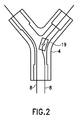
- a temperature sensor or switch 19 may be accommodated in the Y-piece 4, as shown in FIG Fig. 2 is shown.
- An additional temperature switch for example a bimetallic contact with a release temperature of (50 ⁇ 10) ° C, can represent a further safeguard against overheating, for example, when accidentally kinking the fork hose 3 and / or the supply hose 5. Above the trip temperature, the heating circuit is interrupted.
- the in Fig. 2 illustrated temperature switch 19 is a schematic bimetallic contact.
- a temperature sensor or switch 19 alone can effectively prevent condensation since the Y-piece does not end the supply hose 5 heated by the patient's body. Insofar is located in the supply hose 5 of the coldest and thus most susceptible to condensation point between the compressor and nose piece 2. Is the Temperature of the coldest point held above the dew point, no condensation takes place. A displacement of the temperature sensor or switch in the Y-piece 4 can increase the wearing comfort of the air rims 1, because the nose piece 2 can be made lighter and smaller.
- approximately the air temperature in the prongs 12 can be calculated from the temperature in the Y-piece, the heating power and the set flow, a displacement of the temperature sensor from the nosepiece 2 into the Y-piece Piece 4 to no significant loss of comfort.
- Fig. 3 shows a second embodiment of a pair of air goggles, wherein the supply hose 5 and Y-piece 4 are replaced by a double lumen tube 13.
- the double lumen tube consists of two forked tube pieces, which are mechanically connected to each other.
- the Y-piece 4 is omitted or is integrated according to another view in the connector 6.
- a clamp 14 may be provided which prevents further splicing of the double lumen tube.
- the division of an air flow on two forked tube pieces can be done in the plug 6 and is thus further away from the tines 12, so that the noise emission is lower.
- Fig. 4 shows a way to read a temperature sensor over only two heating wires.
- the two heating wires 8 are in the in FIG. 4 shown equivalent circuit diagram represented by the two resistors R H.
- R T represents a two-terminal with temperature-dependent terminal behavior.
- the resistor R T is only a temperature-dependent resistor such as a Pt100 or Pt1000.
- R T is big compared to R H.
- the heating wires typically have a resistance of 15 ⁇ with large tolerances. If a positive heating voltage U H is applied to the three resistors connected in series, then the temperature sensor is short-circuited by the diode D connected in parallel, so that essentially only the heating wires are heated. If a negative or a small measuring voltage UM is applied to the three series-connected resistors, the greater part of the measuring voltage drops at the temperature sensor R T. From this, the temperature of the Temperature sensor can be determined. The remaining voltage drops at the heating resistors can be eliminated.
- diode D serves to bridge and thus protect the integrated circuit for the heating current.
- a Schottky diode can be used for the diode D because of its low forward voltage.
- the direction of the measuring current is directed counter to the heating current. Its amount depends on the temperature and the integrated circuit used and is a few 100 ⁇ A. The particular advantage of this solution is that the wire resistance practically does not affect the measurement result.
- the conversion of the temperature signal by modulating on the heating current is possible. This can be done both analog and digital and realized in customer-specific circuits. Such circuits are known, for example, from telephones or baby monitors for modulating audio frequency signals to the operating voltage.
- the polarity or magnitude of the applied voltage can be switched much faster than the thermal inertia of the system, so that switching between the heater voltage U H and the measurement voltage UM has virtually no temperature change.
- Fig. 4 shows a section through the embodiment of a heating wire 8.
- a metal wire 21 is embedded in an insulation 22.
- the insulation has a star-shaped cross section with five triangular rays and is therefore invariant with respect to rotations by 72 °.
- the metal wire 21 may have a star-shaped cross-section. Each ray forms an elevation running along the wire.
- the bumps can also run helically around the lateral surface, wherein the length of a circulation is typically a multiple of the extent of the insulation.
- the purpose of the star-shaped insulation is to increase the surface area of the wire and thus reduce the thermal resistance to the surrounding air. In addition, even when kinked hose of the heating wire should be circulated as possible on all sides of air, not to overheat and melt into the surrounding tube.
- the triangular rays of the cross section spread the kink of a hose whereby the contact area between the hose and the insulation is small and thus the thermal resistance remains high.
- the metal wire 21 may have a diameter of about 0.3 mm and a circle that just encloses the tips of the cross section have a diameter of 1 mm.
- Fig. 6 shows a section through a hose, which may be a fork hose 3 or a supply hose 5. Both types of tubes typically differ mainly by their diameter.
- the inner circumferential surface of the hose has projections 32, which serve to spread the jacket of the hose at kinks in order not to completely cut off the air flow despite kink.
- stabilizing threads 31 and 33 are on or introduced to reduce a longitudinal expansion of the hose.
- the stabilizing threads 31 and 33 can be introduced into the tubing during the manufacturing process, in particular into protrusions 32.
- the stabilizing threads 31 and 33 may be made of artificial or natural fiber material, plastic or metal.
- the reason for the stabilization threads is that heat-resistant PVC is too stiff and therefore, for example, TPE or silicone must be used.
- TPE thermoplastic polyurethane
- the latter materials are highly elastic, which may be undesirable in the longitudinal direction, because then occurring tensile forces must be absorbed by the heating wire and mechanically stress this and its connections. Since the hoses are operated at maximum pressures of a few 100 millibars, stabilization in the radial direction does not appear necessary.
- the stabilization threads in particular those in projections 32, consist of an electrically conductive material, in particular of metal, possibly surrounded by a thermally stable, not necessarily biocompatible, electrical insulation, these can be used for heating and replace heating wire 8. In this way, problems with non-biocompatible insulation materials can be circumvented.
- fork tube 3 and / or supply hose 5 may be surrounded by a thermal insulation 34.
- insulation can make the surface of the hoses soft and thus more comfortable. From a technical point of view, the insulation has the advantage of reducing the heating power. In the event of a fault, this must remain below 15W if the power control fails and the entire supply voltage is applied. Lowering the heating power therefore makes it possible to use less precisely tolerated and thus cheaper heating wires or longer hoses. The nasal cannulae that are currently being considered actually require almost 15W of maximum heating power.
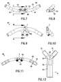
- FIGS. 7, 9 and FIG. 11 show three perspective views of a second embodiment of a nosepiece 42.
- the FIGS. 8 and 10 The second embodiment of the nose piece 42 differs only qualitatively from the embodiment of the nose piece 2.
- To reduce the noise emission nose piece 2 is bulbous, ie, the clear cross-sectional area increases from the hose connections to the tines stronger to. As a result, the flow velocity of the air is reduced in order to keep the noise emission low.
- the reduction of the flow resistance by increasing the cross-sectional area in the nosepiece is negligible because the flow resistance is largely determined by the thickness of forked tube 3.
- three prototypes are being prepared, each with a different increase in cross-sectional area. Measurement results are not available yet.
- Nose piece 42 comprises hose connections 44, hose transition regions 45, connecting pieces 47, tines 52 with annular nubs 53 and a central connecting piece 48 Fig. 11 detects, is located between hose transition areas 45 and hose connectors 44 each an inner radius stage 46, which compensates just the difference between the inner and outer radius of fork tube 3 in order to achieve the smoothest possible transition between the inner surface of the fork tube 3 and nose piece 42.
- the projections 32 may be removed or corresponding projections may be integrally formed on the inner surface of the nose piece 42.
- the transition areas 54 between tines 52 and connectors 47 are generously rounded to reduce noise emission.
- this radius outside is 4.3 mm.
- the outer diameter of the tines is 5.5 mm near the connector and 5 mm near the aperture.
- the wall thickness is about 0.5 mm.
- transition region between the central connector 48 and the tines 52 is also rounded, wherein the outer radius is also in the range between 4 and 5 mm.
- the recess 43 in the central connector 48 is in the FIGS. 8 and 10 on average and in Fig. 9 shown in a plan view. It serves to set a defined flow resistance between the left and right side of the nasal goggles. As in FIG. 1 shown, the goggles is mirror-symmetrical. This is also true in most cases for the user. As long as mirror symmetry is given, no air flows through the central connector 48. The symmetry can be broken, for example, that either the left or right forked tube 3 is bent or the user has runny nose and therefore a nostril swollen. In the former case, it is desirable on the one hand that both tines are supplied via the still open hose. On the other hand, the kinked fork hose is not completely closed.
- a pressure drop at the central connector 48 may be desirable. If a nostril is swollen, it is desirable to apply more air over the other prongs. Also in this case, air flow through the central connector 48 is desirable.
- Fig. 12 the Y-piece 4 is shown enlarged. It can be seen above the two fork hose connections 91 and below the supply hose connection 93.
- the Transition region 95 between the two fork tube connections is rounded and in one embodiment has a radius of 1 mm.
- the fork tubes and the supply hose have an inner radius (without protrusions 32) of 3 and 5 mm, respectively.
- the rounding of transition region 95 is particularly important if, for example, due to bending of a fork tube asymmetric flow conditions exist.
- All ports have inner radius stages 92 and 94 to compensate for the difference between inner radius and outer radius of the connected hoses.
- the inner radius stages may either have projections corresponding to the projections 32 in the connected hoses and / or the projections 32 may be removed at the hose ends.
Abstract
Description
Die Erfindung bezieht sich auf das technische Gebiet von Luftbrillen gemäß dem Oberbegriff des Patentanspruchs 1, von Nasenstücken hierfür gemäß den Oberbegriffen der Patentansprüche 12 bis 15, von Y-Stücken gemäß dem Oberbegriff des Patentanspruchs 16 sowie von Verfahren gemäß dem Oberbegriff von Patentanspruch 19. Insbesondere bezieht sich die Erfindung auf konstruktive Änderungen, die den Einsatz von Luftbrillen bei der pneumatischen Schienung der oberen Atemwege erleichtern.The invention relates to the technical field of goggles according to the preamble of claim 1, of nose pieces therefor according to the preambles of
Obstruktive Atmungsstörungen führen zu Apnoen (Atemstillstand), durch die der Schlafende erwacht. Häufige Apnoen verhindern, dass der Schlafende in den erholsamen Tiefschlaf fällt. Menschen, die Apnoen während des Schlafens erleiden, sind deshalb tagsüber unausgeschlafen, was zu sozialen Problemen am Arbeitsplatz und im schlimmsten Fall zu tödlichen Unfällen, beispielsweise bei Berufskraftfahrern, führen kann.Obstructive respiratory disorders lead to apneas (respiratory arrest), which awakens the sleeping person. Frequent apneas prevent the sleeping person from relaxing in deep sleep. People who suffer apneas during sleep are therefore no sleep during the day, which can lead to social problems in the workplace and in the worst case to fatal accidents, for example in professional drivers.
Im Stand der Technik sind Geräte zur Durchführung der CPAP (continuous positive airway pressure)-Therapie bekannt. Die CPAP-Therapie wird in
In der CPAP-Therapie wird einem Patienten ein konstanter positiver Druck über eine Nasenmaske zugeführt, um die oberen Atemwege zu schienen. Bei richtiger Wahl des Überdrucks gewährleistet dieser, dass die oberen Atemwege während der gesamten Nacht vollständig geöffnet bleiben und somit keine obstruktiven Atemstörungen auftreten. Unter anderem zur Komfortsteigerung wurden BiLevel-Geräte entwickelt, die den Druck während der aus Atempause absenken. Als Oberbegriff für Geräte zur pneumatischen Schienung der oberen Atemwege wird hier der Begriff PAP-Geräte verwendet.In CPAP therapy, a patient is given a constant positive pressure via a nasal mask to appear in the upper airway. If the overpressure is properly selected, it will ensure that the upper airways remain fully open throughout the night, preventing obstructive respiratory disorders. Among other things, to improve comfort BiLevel devices were developed, which lower the pressure during the breather. As generic term for devices for the pneumatic splinting of the upper respiratory tract the term PAP devices is used here.
Schnarchen und Apnoen können die gleiche Ursache haben, nämlich zu schlaffes Gaumen- und Zungengewebe.Snoring and apneas may have the same cause, namely flabby palate and tongue tissue.
Aus dem Stand der Technik sind ferner Sauerstoffbrillen für die Sauerstoffbehandlung bekannt. Mit der Sauerstoffbrille wird dem Patienten Luft mit einem erhöhten Sauerstoffpartialdruck (> 210 mbar) oder reiner Sauerstoff in die Nase appliziert. Eine Sauerstoffbehandlung findet zum Beispiel bei akuter oder chronischer Hypoxämie infolge Atem- oder Herz-Kreislaufstörung (Myokardinfarkt, Schock) oder bestimmten Vergiftungen, zum Beispiel durch Kohlenmonoxid, Kohlendioxid, Leuchtgas oder Rauch statt.Oxygen glasses for oxygen treatment are also known from the prior art. With the oxygen goggles, the patient is air with an increased oxygen partial pressure (> 210 mbar) or pure oxygen in the Nose applied. For example, oxygen treatment occurs in acute or chronic hypoxemia due to respiratory or cardiovascular disorder (myocardial infarction, shock) or certain poisoning, for example, carbon monoxide, carbon dioxide, fluorescent gas or smoke.
Aus der
Vapotherm 2000i ist ein Befeuchtungssystem, das Luftflüsse im Bereich von 8 bis 40 l/min über Luftbrillen (nasal cannula) an Patienten liefert. Die geförderte Luft wird befeuchtet und beheizt. Luft kann mit Sauerstoff angereichert werden.Vapotherm 2000i is a humidification system that delivers air flows in the range of 8 to 40 l / min via nasal cannula to patients. The extracted air is humidified and heated. Air can be enriched with oxygen.
Es ist Aufgabe der Erfindung, eine Luftbrille, ein Nasenstück, ein Y-Stück sowie ein Verfahren anzugeben, die besonders gut zur pneumatischen Schienung der oberen Atemwege geeignet sind.It is an object of the invention to provide a pair of goggles, a nose piece, a Y-piece and a method that are particularly well suited for pneumatic splinting of the upper respiratory tract.
Diese Aufgabe wird durch die Lehre der unabhängigen Ansprüche gelöst.This object is achieved by the teaching of the independent claims.
Bevorzugte Ausführungsformen der Erfindung sind Gegenstand der Unteransprüche.Preferred embodiments of the invention are subject of the dependent claims.
Das Beheizen eines Gabelschlauches mittels eines Heizdrahtes kann die Kompensation von Feuchtigkeit im Gabelschlauch verhindern. Eine Verlegung des Heizdrahtes im Inneren des Gabelschlauches ist fertigungstechnisch einfach. Aufgrund der Wärmeabgabe an die Umgebung des Gabelschlauches sinkt die Temperatur im Gabelschlauch näherungsweise linear mit dem Abstand vom Kompressor. Dieser Temperaturabfall kann durch eine konstante Heizleistung pro Längeneinheit, wie sie eben ein Heizdraht erzeugt, ausgeglichen werden. Bedingt durch die Konstruktion des Schlauches lässt sich die erforderliche Heizleistung für die gesamte Luftbrille kleiner als 15 Watt halten. Andernfalls wären aufgrund von gesetzlichen Vorgaben der Einsatz von brandhemmenden Kunststoffen erforderlich, die in der Regel nicht biokompatibel sind und deren Einsatz deshalb in medizintechnischen Produkten problematisch ist.The heating of a forked tube by means of a heating wire can prevent the compensation of moisture in the forked tube. A laying of the heating wire inside the fork tube is easy to manufacture. Due to the heat dissipation to the environment of the fork tube, the temperature in the fork tube drops approximately linearly with the distance from the compressor. This temperature drop can be compensated by a constant heat output per unit length, as they just created a heating wire. Due to the construction of the hose, the required heat output for the entire air-rollover can be kept below 15 watts. Otherwise, due to legal requirements, the use of fire-retardant plastics would be required, which are generally not biocompatible and whose use is therefore problematic in medical devices.
Eine Messung der Temperatur der applizierten Luft erlaubt es, die Heizleistung eines Heizdrahtes oder einer Heizung in einem Kompressorgehäuse so zu steuern, dass die Temperatur vom Benutzer als angenehm empfunden wird. Ohne Kompensation des Temperaturabfalls im Gabelschlauch wären die Applikationsöffnungen in den Zinken die kältesten Orte. Folglich wird hier am ehesten Luftfeuchtigkeit kondensieren. Aus diesem Grund ist eine Heizleistungssteuerung aufgrund einer Temperaturmessung in der Nähe der Applikationsöffnungen am besten geeignet, Kondensation in der gesamten Luftbrille zu verhindern.A measurement of the temperature of the applied air makes it possible to control the heat output of a heating wire or a heater in a compressor housing in such a way that that the temperature is perceived by the user as pleasant. Without compensation for the temperature drop in the forked tube, the application openings in the tines would be the coldest places. Consequently, air humidity will most likely condense here. For this reason, a heat output control, due to a temperature measurement near the application ports, is best suited to prevent condensation in the entire goggle.
Aus Gründen der Materialeinsparung ist es wünschenswert, den Temperatursensor auch über den Heizdraht auszulesen. Aufgrund der Fortschritte der Integration von Schaltkreisen ist es möglich, digitale Temperatursensoren mit einer akzeptablen Baugröße herzustellen, die ihr Sensorsignal auf den Heizdraht aufmodulieren.For reasons of saving material, it is desirable to read the temperature sensor also on the heating wire. Due to advances in the integration of circuits, it is possible to produce digital temperature sensors of an acceptable size that will modulate their sensor signal onto the heating wire.
Das Abweichen der äußeren Mantelfläche der Isolierung des Heizdrahts von der üblichen Zylinderform durch Erhöhungen und Vertiefungen verhindert, dass bei einem Abknicken des Gabelschlauches der Luftstrom durch den Gabelschlauch zu stark reduziert wird. In so einem Fall besteht die Gefahr, dass der Heizdraht an der Knickstelle überhitzt und in den Gabelschlauch einschmilzt, weil der Heizdraht an der Knickstelle unzureichend gekühlt wird.The deviation of the outer lateral surface of the insulation of the heating wire from the usual cylindrical shape by elevations and depressions prevents that at a kinking of the fork tube, the air flow through the fork tube is reduced too much. In such a case, there is a risk that the heating wire overheated at the kink and melts into the fork tube, because the heating wire is insufficiently cooled at the kink.
Besonders geeignet zur Sicherstellung eines ausreichenden Luftflusses, falls der Gabelschlauch abknickt, sind entlang des Heizdrahtes verlaufende Erhöhungen und Vertiefungen. Ein dreieckförmiger Querschnitt der Erhöhungen sorgt in vorteilhafter Weise dafür, dass die Berührungsfläche zwischen Isolierung des Heizdrahtes und Innenseite des Gabelschlauches sowohl im normalen Betrieb als auch beim Abknicken klein bleibt. Der insgesamt sternförmige Querschnitt der Isolierung vergrößert vorteilhafterweise die Oberfläche der Isolierung und sorgt damit für eine Verringerung des thermischen Widerstands zwischen der Isolierung und der vorbeiströmenden Luft.Particularly suitable for ensuring a sufficient air flow, if the fork tube kinks, are along the heating wire extending ridges and depressions. A triangular cross-section of the elevations advantageously ensures that the contact area between the insulation of the heating wire and the inside of the fork tube remains small both in normal operation and when bent. The overall star-shaped cross-section of the insulation advantageously increases the surface of the insulation and thus provides for a reduction of the thermal resistance between the insulation and the passing air.
Auch in Längsrichtung des Gabelschlauches verlaufende Vorsprünge sorgen in vorteilhafter Weise dafür, dass selbst dann ein ausreichender Luftstrom unter anderem zur Kühlung des Heizdrahtes sichergestellt ist, falls der Gabelschlauch abknickt.Also extending in the longitudinal direction of the fork tube projections provide in an advantageous manner that even then sufficient air flow is ensured inter alia for cooling the heating wire, if the fork tube kinks.
Stabilisierungsfäden dienen dazu, eine Längsdehnung der Schläuche zu reduzieren.Stabilization threads serve to reduce a longitudinal expansion of the tubes.
Die mechanische Verbindung zweier Stücke des Gabelschlauches an ihrem steckerseitigen Ende erlaubt es, ein Y-Stück einzusparen oder dies in den Stecker zu integrieren. Dies führt in vorteilhafter Weise zu einer Reduzierung der Schallemission, weil das in den Stecker integrierte Y-Stück weiter von den Applikationsöffnungen entfernt ist.The mechanical connection of two pieces of the fork tube at its plug-side end makes it possible to save a Y-piece or to integrate this into the plug. This advantageously leads to a reduction of the acoustic emission because the Y-piece integrated in the plug is further away from the application openings.
Innenradiusstufen an unterschiedlichen Verbindungsstellen können gerade die Schlauchstärke kompensieren, sodass nach Befestigung eines Schlauches der Übergang zwischen Schlauch und dem entsprechenden Bauteil glatt ist. An einem glatten Übergang entstehen weniger Wirbel und damit weniger Schall.Inner radius stages at different connection points can just compensate for the hose thickness, so that after attachment of a hose, the transition between the hose and the corresponding component is smooth. A smooth transition creates less vortex and therefore less noise.
Auch die Übergangsbereiche zwischen einem Zinken und dem zentralen Verbindungsstück sowie einem Zinken und dem Verbindungsstück auf der Seite des Zinkens sind abgerundet, um einer Wirbelbildung und damit einer Geräuschemission in vorteilhafter Weise vorzubeugen.Also, the transition areas between a tine and the central connector and a tine and the connector on the side of the tine are rounded to prevent vortex formation and thus a noise emission in an advantageous manner.
Durch eine Einbuchtung im zentralen Verbindungsstück kann ein optimaler Strömungswiderstand des Verbindungsstücks eingestellt werden.By an indentation in the central connector, an optimal flow resistance of the connector can be adjusted.
Im Folgenden wird eine bevorzugte Ausführungsform der Erfindung unter Bezugnahme auf die beiliegenden Zeichnungen näher erläutert. Dabei zeigen:
-
Fig. 1 eine erfindungsgemäße Luftbrille mit einer ersten Ausführungsform eines Nasenstücks; -
Fig. 2 ein Y-Stück mit einem Temperatursensor; -
Fig. 3 eine erfindungsgemäße Luftbrille mit einem Doppellumenschlauch; -
Fig. 4 eine Schaltung zur Temperaturmessung; -
Fig. 5 den Querschnitt eines Heizdrahtes; -
Fig. 6 den Querschnitt eines Schlauches mit Heizdraht; -
Fig. 7 eine perspektivische Ansicht einer zweiten Ausführungsform eines Nasenstücks aus einer ersten Richtung; -
Fig. 8 einen Schnitt durch eine Zinke entlang Z-Z; -
Fig. 9 eine perspektivische Ansicht der zweiten Ausführungsform des Nasenstücks aus einer zweiten Richtung; -
Fig. 10 einen Schnitt entlang M-M; -
Fig. 11 eine perspektivische Ansicht der zweiten Ausführungsform des Nasenstücks aus einer dritten Richtung; und -
Fig. 12 ein Y-Stück für eine erfindungsgemäße Luftbrille.
-
Fig. 1 an inventive goggle with a first embodiment of a nose piece; -
Fig. 2 a Y-piece with a temperature sensor; -
Fig. 3 an inventive goggles with a double lumen tube; -
Fig. 4 a circuit for measuring temperature; -
Fig. 5 the cross section of a heating wire; -
Fig. 6 the cross section of a hose with heating wire; -
Fig. 7 a perspective view of a second embodiment of a nose piece from a first direction; -
Fig. 8 a section through a prong along ZZ; -
Fig. 9 a perspective view of the second embodiment of the nose piece from a second direction; -
Fig. 10 a section along MM; -
Fig. 11 a perspective view of the second embodiment of the nose piece from a third direction; and -
Fig. 12 a Y-piece for a goggle according to the invention.
Stecker 6 weist ein pneumatisches Steckerteil 10, ein elektrisches Steckerteil 9 auf sowie eine Klammer 11 auf. Vom elektrischen Steckerteil 9 führt ein Heizdraht 8 durch Zuleitungsschlauch 5, Y-Stück 4, das rechte Stück von Gabelschlauch 3, den rechten Teil vom Nasenstück 2 zu einem Temperatursensor 7 und von dort durch den linken Teil vom Nasenstück 2, das linke Stück von Gabelschlauch 3, Y-Stück 4 und Zuleitungsschlauch 5 zum elektrischen Steckerteil 9 zurück.
Die Klammer 11 rastet an einer für Stecker 6 vorgesehenen Buchse ein und sichert Stecker 6 gegen unabsichtliches Herausziehen. Ein möglicher Querschnitt von Gabelschlauch 3 und Zuleitungsschlauch 5 wird im Zusammenhang mit
Aus zulassungsrechtlicher Sicht kann es erforderlich werden, im Bereich des Nasenstücks 2 die Isolation von Heizdraht 8 durch eine zusätzliche Trennwand 18 von Zinken 12 abzuschirmen. Heizdraht 8 verläuft dann im Bereich von Nasenstück 2 in einem zusätzlichen Lumen 17.From a regulatory point of view, it may be necessary, in the region of the
Sollen Luftbrillen zur pneumatischen Schienung der oberen Atemwege benutzt werden, so besteht ein Problem in der Geräuschentwicklung aufgrund der hohen Luftflüsse durch die im Vergleich zu Beatmungsschläuchen dünnen Zuleitungsschläuche und Gabelschläuche. Hieraus resultiert eine hohe Strömungsgeschwindigkeit der Luft, die an Kanten zur Entstehung von Geräuschen führt. Deshalb wurde bei der in
Das Bauteil 7 kann in einer weiteren Ausführungsform ein Temperaturschalter 19 sein, den man als Temperatursensor mit schlechter Auflösung von einem Bit verstehen kann. Der Temperaturschalter kann beispielsweise durch einen Bimetallkontakt beispielsweise mit einer Auslösetemperatur im Bereich von 30°C bis 50°C, insbesondere von 40°C, realisiert werden. Falls die Temperatur des Temperaturschalters die Auslösetemperatur übersteigt, wird der Heizkreis unterbrochen.In a further embodiment, the
Zusätzlich oder alternativ zu Bauteil 7 kann ein Temperatursensor oder -schalter 19 im Y-Stück 4 untergebracht sein, wie dies in
Falls im Nasenstück kein Temperatursensor 7 vorgesehen ist, kann ein Temperatursensor oder -schalter 19 allein Kondensation effektiv verhindern, da beim Y-Stück der nicht vom Körper des Patienten erwärmte Zuleitungsschlauch 5 endet. Insofern befindet sich im Zuleitungsschlauch 5 der kälteste und damit für Kondensation anfälligste Punkt zwischen Kompressor und Nasenstück 2. Wird die Temperatur des kältesten Punkts über dem Tau-Punkt gehalten, findet keine Kondensation statt. Eine Verlagerung des Temperatursensors oder Schalters in das Y-Stück 4 kann den Tragekomfort der Luftbrille 1 erhöhen, weil das Nasenstück 2 leichter und kleiner ausgeführt werden kann.If no
Da bei vorgegebener Geometrie der Luftbrille, insbesondere vorgegebenen Schlauchlängen und Durchmessern, aus der Temperatur im Y-Stück, der Heizleistung und dem eingestelltem Fluss näherungsweise die Lufttemperatur in den Zinken 12 berechnet werden kann, führt eine Verlagerung des Temperatursensors vom Nasenstück 2 in das Y-Stück 4 zu keinen nennenswerten Komforteinbussen.Since, given a given geometry of the aerial goggles, in particular predetermined hose lengths and diameters, approximately the air temperature in the
Im einfachsten Fall ist der Widerstand RT lediglich ein temperaturabhängiger Widerstand wie beispielsweise ein Pt100 oder Pt1000. RT ist groß gegenüber RH. Die Heizdrähte haben typischerweise einen Widerstand von 15Ω mit großen Toleranzen. Wird an den drei in Serie geschalteten Widerständen eine positive Heizspannung UH angelegt, so wird der Temperatursensor durch die parallel geschaltete Diode D kurz geschlossen, so dass im Wesentlichen nur die Heizdrähte beheizt werden. Wird an den drei in Serie geschalteten Widerständen eine negative oder eine kleine Messspannung UM angelegt, so fällt der überwiegende Teil der Messspannung am Temperatursensor RT ab. Hieraus kann die Temperatur des Temperatursensors bestimmt werden. Die verbleibenden Spannungsabfälle an den Heizwiderständen können herausgerechnet werden.In the simplest case, the resistor R T is only a temperature-dependent resistor such as a Pt100 or Pt1000. R T is big compared to R H. The heating wires typically have a resistance of 15Ω with large tolerances. If a positive heating voltage U H is applied to the three resistors connected in series, then the temperature sensor is short-circuited by the diode D connected in parallel, so that essentially only the heating wires are heated. If a negative or a small measuring voltage UM is applied to the three series-connected resistors, the greater part of the measuring voltage drops at the temperature sensor R T. From this, the temperature of the Temperature sensor can be determined. The remaining voltage drops at the heating resistors can be eliminated.
Es ist aber auch möglich, eine temperaturabhängige Stromquelle, wie sie zum Beispiel in Form der integrierten Schaltung AD592 vorliegt, als Zweipol RT einzusetzen. In diesem Fall dient die Diode D dazu, die integrierte Schaltung für den Heizstrom zu überbrücken und damit zu schützen. Beispielsweise kann für die Diode D eine Schottky-Diode wegen ihrer geringen Durchlassspannung eingesetzt werden. Die Richtung des Messstroms ist dem Heizstrom entgegen gerichtet. Sein Betrag ist abhängig von der Temperatur und der eingesetzten integrierten Schaltung und beträgt wenige 100µA. Der besondere Vorteil dieser Lösung besteht darin, dass der Drahtwiderstand das Messergebnis praktisch nicht beeinflusst.But it is also possible to use a temperature-dependent current source, as it is present for example in the form of the integrated circuit AD592, as a two-terminal R T. In this case, diode D serves to bridge and thus protect the integrated circuit for the heating current. For example, a Schottky diode can be used for the diode D because of its low forward voltage. The direction of the measuring current is directed counter to the heating current. Its amount depends on the temperature and the integrated circuit used and is a few 100μA. The particular advantage of this solution is that the wire resistance practically does not affect the measurement result.
Neben den direkt analog übertragenden Sensoren ist auch die Umsetzung des Temperatursignals durch Aufmodulation auf den Heizstrom möglich. Dies kann sowohl analog als auch digital erfolgen und in kundenspezifischen Schaltkreisen realisiert werden. Solche Schaltungen sind beispielsweise von Telefonen oder Babyphonen zur Modulation von Tonfrequenzsignalen auf die Betriebsspannung bekannt.In addition to the directly analog transmitting sensors, the conversion of the temperature signal by modulating on the heating current is possible. This can be done both analog and digital and realized in customer-specific circuits. Such circuits are known, for example, from telephones or baby monitors for modulating audio frequency signals to the operating voltage.
Die Polarität oder Höhe der angelegten Spannung kann weitaus schneller als die thermische Trägheit des Systems umgeschaltet werden, sodass das Umschalten zwischen Heizspannung UH und Messspannung UM praktisch keine Temperaturänderung zur Folge hat.The polarity or magnitude of the applied voltage can be switched much faster than the thermal inertia of the system, so that switching between the heater voltage U H and the measurement voltage UM has virtually no temperature change.
Wenn die Stabilisierungsfäden, insbesondere die in Vorsprüngen 32, aus einem elektrisch leitfähigem Material, insbesondere aus Metall, evt. umgeben von einer thermisch beständigen, nicht notwendigerweise biokompatiblen, elektrischen Isolation, bestehen, können diese zur Beheizung eingesetzt werden und Heizdraht 8 ersetzen. Auf diese Weise können Probleme mit nicht-biokompatiblen Isolationsmaterialien umgangen werden.If the stabilization threads, in particular those in
Schließlich können Gabelschlauch 3 und/oder Zuleitungsschlauch 5 von einer thermischen Isolation 34 umgeben sein. Diese sollte nicht zu dick sein, da insbesondere ein dünner Gabelschlauch Komfort und eine dicke Isolation eine Komforteinbuße bedeutet. Andererseits kann eine Isolation die Oberfläche der Schläuche weich und damit angenehmer machen. Aus technischer Sicht hat die Isolation den Vorteil, dass sie die Heizleistung reduziert. Diese muss auch im Fehlerfall bei Ausfall der Leistungsregelung und bei Anliegen der gesamten Versorgungsspannung unter 15W bleiben. Ein Absenken der Heizleistung macht deshalb den Einsatz weniger genau tolerierter und damit billigerer Heizdrähte oder längerer Schläuche möglich. Die im Augenblick angedachten Nasenbrillen benötigen tatsächlich fast 15W maximale Heizleistung.Finally,
Die
Nasenstück 42 umfasst Schlauchanschlüsse 44, Schlauchübergangsbereiche 45, Verbindungsstücke 47, Zinken 52 mit ringförmigen Noppen 53 sowie einem zentralen Verbindungsstück 48. Wie man in
Wie ebenfalls in
Wie in
Der Übergangsbereich zwischen dem zentralen Verbindungsstück 48 und den Zinken 52 ist ebenfalls abgerundet, wobei der Außenradius ebenfalls im Bereich zwischen 4 und 5 mm liegt.The transition region between the
Die Einbuchtung 43 im zentralen Verbindungsstück 48 ist in den
In den
In
Obwohl die Erfindung oben im Zusammenhang mit dem Gas Luft erläutert wurde, kann natürlich auch jedes andere, atembare Gasgemisch verwendet werden. Ganz abgesehen davon ist die Zusammensetzung von Luft beispielsweise hinsichtlich ihres Wasser- und Sauerstoffanteils nicht exakt festgelegt.Although the invention has been explained above in connection with the gas air, of course, any other, breathable gas mixture can be used. Quite apart from that, the composition of air, for example, in terms of their water and oxygen content is not exactly defined.
Den oben beschriebenen Ausführungsformen kann folgende Merkmalsanalyse zu Grunde gelegt werden:
- Eine 1. Luftbrille für ein Antischnarch- oder PAP-Gerät mit:
- einem Gabelschlauch (3), der mit Öffnungen (12; 52) pneumatisch verbunden ist, die so ausgestaltet und positioniert sind, dass über diese Öffnungen (12; 52) Luft in die Nase eines Benutzers appliziert werden kann,
- gekennzeichnet durch:
- einen Heizdraht (8, 31, 33), der im Gabelschlauch (3) verläuft, so dass der Heizdraht (8) die durch den Gabelschlauch (3) zugeführte Luft erwärmen kann.
Eine 2. Luftbrille gemäß der 1. Luftbrille, dadurch gekennzeichnet, dass ein Temperatursensor (7) in der Nähe der Öffnungen (12; 52) angebracht ist, sodass der Temperatursensor (7) die Temperatur der über die Öffnungen (12; 52) applizierten Luft messen kann.Eine 3. Luftbrille gemäß der 2. Luftbrille, dadurch gekennzeichnet, dass der Temperatursensor (7) mit dem Heizdraht (8) so verbunden ist, dass er über den Heizdraht (8) mit elektrischer Energie versorgt werden kann und das Temperatursignal des Temperatursensors (7) auch über den Heizdraht (8) ausgelesen werden kann.Eine 4. Luftbrille gemäß der 3. Luftbrille, dadurch gekennzeichnet, dass der Temperatursensor (7) ein digitaler Temperatursensor ist, der sein Temperatursignal auf die Spannung aufmoduliert, die dem Temperatursensor (7) über den Heizdraht (8) zugeführt wird.Eine 5. Luftbrille gemäß einer der obigen Luftbrillen, dadurch gekennzeichnet, dass der Heizdraht (8) einen drahtförmigen Metallkern (21) aufweist, der von einer Isolierung (22) umgeben ist, deren äußere Mantelfläche Erhöhungen und Vertiefungen aufweist.Eine 6. Luftbrille gemäß der 5. Luftbrille, dadurch gekennzeichnet, dass die Mantelfläche der Isolierung (22) etwa in Längsrichtung des Heizdrahtes (8) verlaufende Erhöhungen mit dreieckförmigen Querschnitten aufweist, sodass die Isolierung (22) insgesamt einen sternförmigen Querschnitt aufweist.Eine 7. Luftbrille gemäß der 5.oder 6. Luftbrille, dadurch gekennzeichnet, dass auch der Metallkern (21) auf seiner Mantelfläche Erhöhungen und Vertiefungen aufweist.Eine 8. Luftbrille gemäß einer der obigen Luftbrillen, dadurch gekennzeichnet, dass der Gabelschlauch (3) Stabilisierungsfäden (31, 33) aufweist.- Eine 9. Luftbrille gemäß einer der obigen Luftbrillen, dadurch gekennzeichnet, dass zwei Stücke des Gabelschlauches (3) an einem steckerseitigen Ende mechanisch zu einem Doppellumenschlauch (13) verbunden sind.
Eine 10. Luftbrille gemäß einer der obigen Luftbrillen, dadurch gekennzeichnet, dass der Gabelschlauch (3) pneumatisch mit einem pneumatischen Steckerteil (10) eines Steckers (6) und der Heizdraht (8) elektrisch mit einem elektrischen Steckerteil (9) des Steckers (6) verbunden sind.Eine 11. Luftbrille gemäß einer der obigen Luftbrillen, dadurch gekennzeichnet, dass die Öffnungen durch Zinken (12, 52) etwa in der Mitte eines Nasenstücks (2, 42) gebildet werden, wobei ein linkes Stück des Gabelschlauches (3) an der linken Seite des Nasenstücks (2, 42) und ein rechtes Stück des Gabelschlauches (3) an der rechten Seite des Nasenstücks (2, 42) pneumatisch angeschlossen sind und der Heizdraht (8, 31, 33) vom linken Stück des Gabelschlauches (3) durch das Innere des Nasenstücks (2, 42) zum rechten Stück des Gabelschlauches (3) verläuft.- Ein 1. Nasenstück für eine Luftbrille insbesondere gemäß einer der obigen Luftbrillen, mit:
- einer Verbindungsstelle (44) zum Anbringen eines Gabelschlauches (3);
- dadurch gekennzeichnet, dass die Verbindungsstelle eine Innenradiusstufe (46) an einem Ende der Verbindungsstelle (44) aufweist, deren Höhe gerade der halben Differenz zwischen Innen- und Außendurchmesser des Gabelschlauches (3) entspricht, sodass sich bei Anbringen eines Gabelschlauches (3) an der Verbindungsstelle (44) ein glatter Übergang zwischen dem Inneren des Gabelschlauches (3) und dem Inneren des Nasenstücks ergibt.
Ein 2. Nasenstück, insbesondere gemäß dem 1. Nasenstück, für eine Luftbrille insbesondere gemäß einer der 1.bis 11. Luftbrillen, mit:- einem Zinken (12; 52) zum Applizieren von Luft in ein Nasenloch eines Benutzers;
- einer Verbindungsstelle (44) zum Anbringen eines Gabelschlauches (3); und
- einem Verbindungsstück (47), das den Zinken (12; 52) mit der Verbindungsstelle (44) mechanisch und pneumatisch verbindet,
- dadurch gekennzeichnet, dass der Übergangsbereich (54) zwischen dem Zinken (12; 52) und dem Verbindungsstück (47) einen Radius in einer durch den Zinken und das Verbindungsstück (47) festgelegten Ebene aufweist, der größer als der Radius des Zinken (12; 52) ist.
Ein 3. Nasenstück, insbesondere gemäß dem 1.oder 2. Nasenstück, für eine Luftbrille insbesondere gemäß einer der 1.bis 11. Luftbrillen, mit:- zwei Zinken (12; 52) zum Applizieren von Luft in je ein Nasenloch eines Benutzers;
- einem zentralen Verbindungsstück (48), das die beiden Zinken (12; 52) mechanisch und pneumatisch verbindet;
- zwei Schlauchanschlüsse (44); und
- zwei Verbindungsstücke (47), wobei jedes Verbindungsstück je einen Zinken (12; 52) mit einem Schlauchanschluss (44) mechanisch und pneumatisch verbindet,
- dadurch gekennzeichnet, dass
- das zentrale Verbindungsstück (48) eine Einbuchtung (43) aufweist, so dass die Fläche des lichten Querschnitts des zentralen Verbindungsstücks (48) kleiner als die Fläche der lichten Querschnitte der beiden Verbindungsstücke (47) ist.
Ein 4. Nasenstück, insbesondere gemäß einem der 1.bis 3. Nasenstücke, für eine Luftbrille insbesondere gemäß einer der 1.bis 11. Luftbrillen, mit:- zwei Zinken (12; 52) zum Applizieren von Luft in je ein Nasenloch eines Benutzers;
- einem zentralen Verbindungsstück (48), das die beiden Zinken (12; 52) mechanisch und pneumatisch verbindet;
- dadurch gekennzeichnet, dass
- der Übergangsbereich zwischen dem zentralen Verbindungsstück (48) in einer durch die beiden Zinken (12; 52) definierten Ebene abgerundet ist, wobei der Radius dieses Übergangsbereichs größer als der Radius der Zinken ist.
- Ein 1. Y-Stück für eine Luftbrille insbesondere gemäß einer der 1.
bis 8. Luftbrillen, mit:- zwei Gabelschlauchanschlüssen (91); und
- einem Zuleitungsschlauchanschluss (93), wobei das Y-Stück alle drei Schlauchanschlüsse mechanisch und pneumatisch verbindet,
- dadurch gekennzeichnet, dass
- jeder der beiden Gabelschlauchanschlüsse (91) eine Innenradiusstufe (92) an einem Ende des Gabelschlauchanschlusses (91) aufweist, deren Höhe gerade der halben Differenz zwischen Innen- und Außendurchmesser des Gabelschlauches (3) entspricht, sodass sich bei Anbringen eines Gabelschlauches (3) an einem Gabelschlauchanschluss (91) ein glatter Übergang zwischen dem Inneren des Gabelschlauches (3) und dem Inneren des Y-Stücks (4) ergibt.
Ein 2. Y-Stück gemäß dem 1. Y-Stück, dadurch gekennzeichnet, dass der Zuleitungsschlauchanschluss (93) eine Innenradiusstufe (94) an einem Ende des Zuleitungsschlauchanschlusses (93) aufweist, deren Höhe gerade der halben Differenz zwischen Innen- und Außendurchmesser des Zuleitungsschlauches (5) entspricht, so dass sich bei Anbringen eines Zuleitungsschlauches (5) am Zuleitungsschlauchanschluss (93) ein glatter Übergang zwischen dem Inneren des Zuleitungsschlauches (5) und dem Inneren des Y-Stücks (4) ergibt.Ein 3. Y-Stück gemäß dem 1.oder 2. Y-Stück, dadurch gekennzeichnet, dass der Übergangsbereich (95) zwischen den beiden Gabelschlauchanschlüssen (91) im Inneren des Y-Stücks (4) abgerundet ist, wobei der Radius in diesem Übergangsbereich (95) in einer durch die beiden Gabelschlauchanschlüsse (91) definierten Ebene größer als ein Zehntel des lichten Querschnitts eines Gabelschlauchanschlusses (91) ist.- Ein 1. Verfahren zur Vermeidung von Kondensation in einer Luftbrille mit:
- Zuführen (6) eines Gases zur Luftbrille; und
- Applizieren des Gases durch Öffnungen (12; 52) in der Luftbrille;
- gekennzeichnet durch:
- Heizen (8) des Gases während es durch die Schläuche der Luftbrille strömt.
Ein 2. Verfahren gemäß dem 1. Verfahren, gekennzeichnet durch:- Messen (7) der Temperatur in der Nähe der Öffnungen (12; 52) zum Applizieren des Gases; und
- Steuern der Heizleistung, so dass eine Kondensation in der Luftbrille vermieden wird.
Ein 3. Verfahren gemäß dem 1.oder 2. Verfahren, dadurch gekennzeichnet, dass ein Temperatursensor (7), der die Temperatur in der Nähe der Öffnungen (12; 52) misst, über Heizdrähte (8) zum Heizen des Gases mit elektrische Energie versorgt wird und die Heizdrähte (8) zur Übertragung des Sensorsignals verwendet werden.
- A 1. Aerial goggles for an anti-snore or PAP device with:
- a fork tube (3) pneumatically connected to openings (12; 52) configured and positioned to allow air to be applied to the nose of a user via these openings (12; 52),
- marked by:
- a heating wire (8, 31, 33) extending in the fork tube (3) so that the heating wire (8) can heat the air supplied through the fork tube (3).
- A second air-raid according to the first air-raid, characterized in that a temperature sensor (7) in the vicinity of the openings (12; 52) is mounted, so that the temperature sensor (7) applied the temperature of the via the openings (12; Air can measure.
- A 3rd Aerial goggles according to the 2nd Luftbrille, characterized in that the temperature sensor (7) with the heating wire (8) is connected so that it can be supplied via the heating wire (8) with electrical energy and the temperature signal of the temperature sensor (7 ) can also be read via the heating wire (8).
- 4. A pair of aerial goggles according to the 3rd aerial goggles, characterized in that the temperature sensor (7) is a digital temperature sensor which modulates its temperature signal to the voltage supplied to the temperature sensor (7) via the heating wire (8).
- 5. A goggle according to one of the above goggles, characterized in that the heating wire (8) has a wire-shaped metal core (21) which is surrounded by an insulation (22) whose outer circumferential surface has elevations and depressions.
- 6. A goggles according to the 5th Luftbrille, characterized in that the lateral surface of the insulation (22) approximately in the longitudinal direction of the heating wire (8) extending elevations having triangular cross-sections, so that the insulation (22) has a total of a star-shaped cross-section.
- A 7. Luftbrille according to the 5th or 6th Aerial, characterized in that also the metal core (21) has on its lateral surface elevations and depressions.
- 8. An aerial goggle according to one of the above goggles, characterized in that the fork tube (3) stabilizing threads (31, 33).
- A 9th goggles according to one of the above goggles, characterized in that two pieces of the fork tube (3) are mechanically connected at a plug-side end to a double lumen tube (13).
- A goggle according to one of the above goggles, characterized in that the fork hose (3) is pneumatically connected to a pneumatic plug part (10) of a plug (6) and the heating wire (8) is electrically connected to an electrical plug part (9) of the plug (6 ) are connected.
- 11. An aerial goggle according to any one of the above goggles, characterized in that the openings are formed by prongs (12, 52) approximately in the center of a nose piece (2, 42), with a left piece of the fork tube (3) on the left side the nose piece (2, 42) and a right piece of the fork tube (3) on the right side of the nose piece (2, 42) are pneumatically connected and the heating wire (8, 31, 33) from the left piece of the fork tube (3) through the Inner of the nose piece (2, 42) to the right piece of the fork tube (3) extends.
- A first nosepiece for a pair of aviation goggles, in particular according to one of the above goggles, comprising:
- a junction (44) for attaching a fork tube (3);
- characterized in that the junction has an inner radius step (46) at one end of the junction (44) whose height is equal to half the difference between inner and outer diameters of the fork tube (3) so that when attaching a forked tube (3) to the Junction (44) results in a smooth transition between the interior of the fork tube (3) and the interior of the nose piece.
- A second nosepiece, in particular in accordance with the first nose piece, for a pair of air raids, in particular according to one of the 1st to 11th air goggles, comprising:
- a prong (12; 52) for applying air to a nostril of a user;
- a junction (44) for attaching a fork tube (3); and
- a connector (47) mechanically and pneumatically connecting the prongs (12; 52) to the connector (44);
- characterized in that the transition region (54) between the tine (12; 52) and the connecting piece (47) has a radius in a plane defined by the tine and the connecting piece (47) greater than the radius of the tine (12; 52).
- A third nose piece, in particular according to the 1st or 2nd nose piece, for a pair of air rims, in particular according to one of the 1st to 11th air glasses, comprising:
- two prongs (12; 52) for applying air to each nostril of a user;
- a central connector (48) mechanically and pneumatically connecting the two prongs (12; 52);
- two hose connections (44); and
- two connecting pieces (47), each connecting piece each mechanically and pneumatically connecting a tine (12; 52) to a hose connection (44),
- characterized in that
- the central connecting piece (48) has a recess (43), so that the area of the clear cross section of the central connecting piece (48) is smaller than the area of the clear cross sections of the two connecting pieces (47).
- A fourth nose piece, in particular according to one of the 1st to 3rd nose pieces, for a pair of aerial goggles, in particular according to one of the 1st to 11th air glasses, comprising:
- two prongs (12; 52) for applying air to each nostril of a user;
- a central connector (48) mechanically and pneumatically connecting the two prongs (12; 52);
- characterized in that
- the transition area between the central connecting piece (48) is rounded off in a plane defined by the two prongs (12; 52), the radius of this transitional area being greater than the radius of the prongs.
- A first Y-piece for a pair of goggles, in particular according to one of the 1st to 8th air goggles, comprising:
- two fork hose connections (91); and
- a supply hose connection (93), the Y-piece mechanically and pneumatically connecting all three hose connections,
- characterized in that
- each of the two fork hose connections (91) has an inner radius step (92) at one end of the fork hose connection (91) whose height is just half the difference between inner and outer diameter of the fork hose (3), so that when attaching a fork hose (3) a smooth transition between the interior of the fork tube (3) and the interior of the Y-piece (4) results in a fork tube connection (91).
- A second Y-piece according to the first Y-piece, characterized in that the supply hose connection (93) has an inner radius stage (94) at one end of the supply hose connection (93) whose height is just half the difference between the inner and outer diameter of Supply hose (5) corresponds, so that when attaching a supply hose (5) at the supply hose connection (93) results in a smooth transition between the interior of the supply hose (5) and the interior of the Y-piece (4).
- A third Y-piece according to the first or second Y-piece, characterized in that the transition region (95) between the two forked hose connections (91) in the interior of the Y-piece (4) is rounded, the radius in this Transition region (95) in a plane defined by the two fork hose connections (91) is greater than one-tenth of the clear cross-section of a fork hose connection (91).
- A first method for preventing condensation in a goggle with:
- Supplying (6) a gas to the aerial goggles; and
- Applying the gas through openings (12; 52) in the goggle;
- marked by:
- Heating (8) the gas as it flows through the hoses of the aerial goggles.
- A second method according to the first method, characterized by:
- Measuring (7) the temperature near the openings (12; 52) for applying the gas; and
- Controlling the heating power so that condensation in the aerial goggles is avoided.
- A third method according to the first or second method, characterized in that a temperature sensor (7) which measures the temperature in the vicinity of the openings (12; 52) via heating wires (8) for heating the gas with electrical energy is supplied and the heating wires (8) are used to transmit the sensor signal.
- 11
- Luftbrillenasal cannula
- 22
- Nasenstücknosepiece
- 33
- Gabelschlauchforked tube
- 44
- Y-StückY-piece
- 55
- Zuleitungsschlauchsupply hose
- 66
- Steckerplug
- 77
- Temperatursensortemperature sensor
- 88th
- Heizdrahtheating wire
- 99
- elektrisches Steckerteilelectric plug part
- 1010
- pneumatisches Steckerteilpneumatic connector
- 1111
- Klammerclip
- 1212
- Zinkeprong
- 1313
- DoppellumenschlauchDouble-lumen tube
- 1414
- Schelleclamp
- 1616
- InnenradiusstufeInner radius Level
- 1717
- zusätzliches Lumenadditional lumen
- 1818
- Trennwandpartition wall
- 1919
- Temperaturschaltertemperature switch
- 2121
- Metalldrahtmetal wire
- 2222
- Isolationisolation
- 3131
- Stabilisierungsfadenstabilization thread
- 3232
- Vorsprunghead Start
- 3333
- Stabilisierungsfadenstabilization thread
- 3434
- thermische Isolationthermal insulation
- 4242
- Nasenstücknosepiece
- 4343
- Einbuchtungindentation
- 4444
- Schlauchanschlusshose connection
- 4545
- SchlauchübergangsbereichHose transition area
- 4646
- InnenradiusstufeInner radius Level
- 4747
- Verbindungsstückjoint
- 4848
- zentrales Verbindungsstückcentral connector
- 5252
- Zinkeprong
- 5353
- Noppeburl
- 5454
- ZinkenübergangsbereichZinc transition area
- 9191
- GabelschlauchanschlussFork hose connection
- 9292
- InnenradiusstufeInner radius Level
- 9393
- ZuleitungsschlauchanschlussSupply hose connection
- 9494
- InnenradiusstufeInner radius Level
- 9595
- ÜbergangsbereichTransition area
Claims (20)
Applications Claiming Priority (3)
| Application Number | Priority Date | Filing Date | Title |
|---|---|---|---|
| DE102005000922A DE102005000922A1 (en) | 2005-01-07 | 2005-01-07 | Aerial goggles, nosepiece, Y-piece and procedures |
| EP07113959A EP1859831B1 (en) | 2005-01-07 | 2005-12-30 | Nasal cannula |
| EP05850200A EP1715909B1 (en) | 2005-01-07 | 2005-12-30 | Nasal cannula |
Related Parent Applications (4)
| Application Number | Title | Priority Date | Filing Date |
|---|---|---|---|
| EP05850200.6 Division | 2005-12-30 | ||
| EP05850200A Division EP1715909B1 (en) | 2005-01-07 | 2005-12-30 | Nasal cannula |
| EP07113959A Division EP1859831B1 (en) | 2005-01-07 | 2005-12-30 | Nasal cannula |
| EP07113959.6 Division | 2007-08-07 |
Publications (3)
| Publication Number | Publication Date |
|---|---|
| EP2374494A2 true EP2374494A2 (en) | 2011-10-12 |
| EP2374494A3 EP2374494A3 (en) | 2012-02-22 |
| EP2374494B1 EP2374494B1 (en) | 2017-03-01 |
Family
ID=36127291
Family Applications (3)
| Application Number | Title | Priority Date | Filing Date |
|---|---|---|---|
| EP05850200A Active EP1715909B1 (en) | 2005-01-07 | 2005-12-30 | Nasal cannula |
| EP07113959A Active EP1859831B1 (en) | 2005-01-07 | 2005-12-30 | Nasal cannula |
| EP10186319.9A Active EP2374494B1 (en) | 2005-01-07 | 2005-12-30 | Nose piece for nasal cannula |
Family Applications Before (2)
| Application Number | Title | Priority Date | Filing Date |
|---|---|---|---|
| EP05850200A Active EP1715909B1 (en) | 2005-01-07 | 2005-12-30 | Nasal cannula |
| EP07113959A Active EP1859831B1 (en) | 2005-01-07 | 2005-12-30 | Nasal cannula |
Country Status (9)
| Country | Link |
|---|---|
| US (2) | US20090025723A1 (en) |
| EP (3) | EP1715909B1 (en) |
| JP (1) | JP5026281B2 (en) |
| CN (1) | CN101098726B (en) |
| AT (2) | ATE375178T1 (en) |
| DE (4) | DE102005000922A1 (en) |
| ES (3) | ES2621654T3 (en) |
| PT (1) | PT2374494T (en) |
| WO (1) | WO2006072231A2 (en) |
Families Citing this family (58)
| Publication number | Priority date | Publication date | Assignee | Title |
|---|---|---|---|---|
| US7481219B2 (en) * | 2004-06-18 | 2009-01-27 | Mergenet Medical, Inc. | Medicine delivery interface system |
| WO2007019628A1 (en) | 2005-08-15 | 2007-02-22 | Resmed Ltd | Low cost cpap flow generator and humidifier assembly |
| DE102006019402A1 (en) * | 2006-04-24 | 2007-10-25 | Seleon Gmbh | Method for controlling a TNI device and TNI device |
| GB0610171D0 (en) | 2006-05-23 | 2006-06-28 | Robitaille Jean Pierre | Valved nasal canula |
| CN110141752B (en) | 2006-11-08 | 2022-03-04 | 瑞思迈私人有限公司 | Catheter for use in a respiratory device |
| US8171935B2 (en) | 2006-11-15 | 2012-05-08 | Vapotherm, Inc. | Nasal cannula with reduced heat loss to reduce rainout |
| US8196579B2 (en) * | 2007-08-29 | 2012-06-12 | Smiths Medical Asd, Inc. | Nose cannula heated/humidified gas delivery system |
| US8215301B2 (en) * | 2007-08-29 | 2012-07-10 | Smiths Medical Asd, Inc. | Nose cannula heated/humidified gas delivery system |
| US8551534B2 (en) | 2007-10-10 | 2013-10-08 | Parion Sciences, Inc. | Inhaled hypertonic saline delivered by a heated nasal cannula |
| AU2009206372A1 (en) * | 2008-01-25 | 2009-07-30 | Salter Labs | Respiratory therapy system including a nasal cannula assembly |
| DE102008010475A1 (en) | 2008-02-21 | 2009-08-27 | Seleon Gmbh | Applicators for a pair of aerial goggles |
| US9802022B2 (en) | 2008-03-06 | 2017-10-31 | Resmed Limited | Humidification of respiratory gases |
| DE102009047246A1 (en) * | 2008-12-01 | 2010-06-10 | Fisher & Paykel Healthcare Ltd., East Tamaki | nasal cannula |
| AU2010206053B2 (en) | 2009-07-31 | 2014-08-07 | ResMed Pty Ltd | Wire Heated Tube with Temperature Control System, Tube Type Detection, and Active Over Temperature Protection for Humidifier for Respiratory Apparatus |
| US20110282248A1 (en) * | 2010-03-04 | 2011-11-17 | Martin Ruth E | Portable high frequency air pulse delivery device |
| US20110315148A1 (en) * | 2010-06-12 | 2011-12-29 | Widgerow Alan D | Skin adherent medical devices |
| US20110303224A1 (en) * | 2010-06-12 | 2011-12-15 | Widgerow Alan D | Skin adherent medical devices |
| US20120203127A1 (en) * | 2011-02-07 | 2012-08-09 | Slp Ltd. | Nasal cannula with integrated thermal flow sensing |
| CA2838529C (en) | 2011-06-07 | 2020-03-24 | Parion Sciences, Inc. | Methods of treatment |
| US9308341B2 (en) * | 2011-08-04 | 2016-04-12 | Travis Ray NEELY | Oxygen delivery apparatus, system, and method |
| CA2850156C (en) | 2011-09-29 | 2022-08-16 | Trudell Medical International | Nasal insert and cannula and methods for the use thereof |
| US9212673B2 (en) | 2011-09-30 | 2015-12-15 | Carefusion 207, Inc. | Maintaining a water level in a humidification component |
| US10168046B2 (en) | 2011-09-30 | 2019-01-01 | Carefusion 207, Inc. | Non-metallic humidification component |
| US9205220B2 (en) * | 2011-09-30 | 2015-12-08 | Carefusion 207, Inc. | Fluted heater wire |
| US8733348B2 (en) | 2011-09-30 | 2014-05-27 | Carefusion 207, Inc. | Humidifying respiratory gases |
| US9067036B2 (en) * | 2011-09-30 | 2015-06-30 | Carefusion 207, Inc. | Removing condensation from a breathing circuit |
| CN102688547A (en) * | 2011-11-22 | 2012-09-26 | 河南科技大学 | Air regulating unit and a miniature air regulator composed of same |
| USD665496S1 (en) * | 2011-12-06 | 2012-08-14 | Galemed Corporation | Nasal cannula |
| US9272113B2 (en) | 2012-03-30 | 2016-03-01 | Carefusion 207, Inc. | Transporting liquid in a respiratory component |
| AU2013240675B2 (en) | 2012-03-30 | 2017-10-19 | Fisher & Paykel Healthcare Limited | Humidification system |
| CN107596522B (en) | 2012-06-25 | 2021-08-31 | 费雪派克医疗保健有限公司 | Medical component with microstructures for humidification and condensate management |
| KR101449920B1 (en) | 2012-09-12 | 2014-10-08 | (주)유 바이오메드 | Body temperature regulating breathing using repiratory gas mask |
| US10300236B2 (en) * | 2012-10-31 | 2019-05-28 | Vapotherm, Inc. | Quiet nasal cannula |
| CN104902964A (en) * | 2012-11-27 | 2015-09-09 | 威廉马歇莱思大学 | Bubble continuous positive airway pressure |
| DK2928531T3 (en) | 2012-12-04 | 2017-05-22 | Ino Therapeutics Llc | CANNEL FOR MINIMIZING DILUTION DOSAGE DURING NITROGEN OXIDE ADMINISTRATION |
| US9795756B2 (en) | 2012-12-04 | 2017-10-24 | Mallinckrodt Hospital Products IP Limited | Cannula for minimizing dilution of dosing during nitric oxide delivery |
| EP3034122B1 (en) * | 2012-12-20 | 2020-09-16 | Koninklijke Philips N.V. | Inline adapter for a respiratory therapy device |
| CN110742612A (en) | 2013-01-08 | 2020-02-04 | 卡普尼亚公司 | Breath selection for analysis |
| NZ727820A (en) | 2013-02-01 | 2018-06-29 | Resmed Ltd | Wire heated tube with temperature control system for humidifier for respiratory apparatus |
| WO2014127044A1 (en) | 2013-02-12 | 2014-08-21 | Capnia, Inc. | Sampling and storage registry device for breath gas analysis |
| JP6490602B2 (en) | 2013-03-14 | 2019-03-27 | フィッシャー アンド ペイケル ヘルスケア リミテッド | Medical parts with microstructure for humidification and condensate management |
| EP3939643A1 (en) * | 2013-03-15 | 2022-01-19 | Fisher & Paykel Healthcare Limited | Nasal cannula assemblies |
| US9561341B2 (en) * | 2013-05-17 | 2017-02-07 | Katarina Short | Humidification of ventilator gases |
| ES2817076T3 (en) | 2013-08-09 | 2021-04-06 | Fisher & Paykel Healthcare Ltd | Asymmetric Nasal Delivery Elements and Accessories for Nasal Interfaces |
| CA2922347A1 (en) * | 2013-08-30 | 2015-03-05 | Capnia, Inc. | Columnar flow gas sampling and measurement system |
| SG11201601442UA (en) | 2013-08-30 | 2016-03-30 | Capnia Inc | Neonatal carbon dioxide measurement system |
| CN105979995A (en) | 2013-10-16 | 2016-09-28 | 费雪派克医疗保健有限公司 | A patient interface |
| DE102013017348B3 (en) * | 2013-10-18 | 2014-11-13 | Tni Medical Ag | Multifunctional, mobile applicator |
| PL3193995T3 (en) * | 2014-09-19 | 2022-12-05 | Fisher&Paykel Healthcare Limited | Patient interface |
| JP6386667B2 (en) * | 2014-11-13 | 2018-09-05 | ティエヌアイ メディカル アーゲー | Multifunctional applicator for mobile use |
| EP3341509B1 (en) | 2015-08-26 | 2020-04-15 | Picanol | Drive mechanism with a sensor device for driving a heald frame of a weaving machine |
| US11766537B2 (en) * | 2016-07-22 | 2023-09-26 | Fisher & Paykel Healthcare Limited | Sensing for respiratory circuits |
| USD870269S1 (en) | 2016-09-14 | 2019-12-17 | Fisher & Paykel Healthcare Limited | Nasal cannula assembly |
| DE202017001233U1 (en) | 2017-03-07 | 2017-05-22 | Norbert Neubauer | Face and breathing bowl |
| US11110306B2 (en) * | 2018-01-05 | 2021-09-07 | Carlos Alberto Estrada Montoya | Portable device for heating the air that enters the nose of a user |
| DE202020001147U1 (en) | 2020-03-24 | 2020-04-15 | Norbert Neubauer | Filter holder with eye protection |
| DE202020001359U1 (en) | 2020-04-03 | 2020-04-22 | Norbert Neubauer | Breathing mask |
| DE202020001511U1 (en) | 2020-04-11 | 2020-05-07 | Norbert Neubauer | Protective mask |
Citations (1)
| Publication number | Priority date | Publication date | Assignee | Title |
|---|---|---|---|---|
| WO2002062413A2 (en) | 2001-02-06 | 2002-08-15 | Seleon Gmbh | Anti-snoring device, method for reducing snoring and air glasses |
Family Cites Families (48)
| Publication number | Priority date | Publication date | Assignee | Title |
|---|---|---|---|---|
| US2104266A (en) * | 1935-09-23 | 1938-01-04 | William J Mccormick | Means for the production and inhalation of tobacco fumes |
| US4682010A (en) * | 1983-03-07 | 1987-07-21 | Safeway Products, Inc. | In-line electric heater for an aerosol delivery system |
| GB2173274B (en) * | 1985-04-04 | 1989-02-01 | Boc Group Plc | Improvements in inhalation apparatus |
| AU581986B2 (en) * | 1985-05-22 | 1989-03-09 | Fisher & Paykel Healthcare Limited | Improvements in or relating to methods of and/or apparatus for humidifying gases |
| DD238922B1 (en) * | 1985-07-03 | 1989-10-04 | Schwarze Pumpe Gas Veb | APPARATUS FOR AIR GAS CLIMATIZATION IN INTENSIVE THERAPY |
| US4738401A (en) * | 1987-02-24 | 1988-04-19 | Spraying Systems Co. | Quick disconnect nozzle assembly with twist-on spray tip |
| JPH034248Y2 (en) * | 1987-09-16 | 1991-02-04 | ||
| JPH041954Y2 (en) * | 1988-09-09 | 1992-01-23 | ||
| US4967744A (en) * | 1988-11-03 | 1990-11-06 | Airoflex Medical, Inc. | Flexible breathing circuit |
| US4989599A (en) * | 1989-01-26 | 1991-02-05 | Puritan-Bennett Corporation | Dual lumen cannula |
| JPH0340731U (en) * | 1989-08-29 | 1991-04-18 | ||
| JPH04164458A (en) * | 1990-10-26 | 1992-06-10 | Aika:Kk | Warming/humidifying device for respirator |
| JP2582720Y2 (en) * | 1991-08-15 | 1998-10-08 | いすゞ自動車株式会社 | NOx sensor |
| US5477852A (en) * | 1991-10-29 | 1995-12-26 | Airways Ltd., Inc. | Nasal positive airway pressure apparatus and method |
| JPH05296676A (en) * | 1992-04-15 | 1993-11-09 | Ntc Kogyo Kk | Heat accumulator |
| JPH0623051A (en) * | 1992-07-06 | 1994-02-01 | Toransumedo Kk | Heating/humidifying apparatus |
| JPH06114003A (en) * | 1992-10-07 | 1994-04-26 | Olympus Optical Co Ltd | Bending driver for long-sized body using shape memory alloy |
| US5392770A (en) * | 1993-06-29 | 1995-02-28 | Clawson; Burrell E. | Tubing circuit systems for humidified respiratory gas |
| GB2284356B (en) * | 1993-11-22 | 1997-10-29 | Fisher & Paykel | Respiratory humidifier conduit |
| US5465728A (en) * | 1994-01-11 | 1995-11-14 | Phillips; Michael | Breath collection |
| US5513635A (en) * | 1995-02-02 | 1996-05-07 | Bedi; Shan | Nasal cannula anchoring apparatus |
| DE19617095C1 (en) * | 1996-04-29 | 1997-12-04 | Ruesch Willy Ag | Heated ventilation hose |
| DE19746742A1 (en) * | 1997-10-23 | 1999-05-06 | Messer Austria Gmbh | Inhalation gas supply |
| US20020185126A1 (en) * | 1997-01-17 | 2002-12-12 | Christian Krebs | Controlled gas-supply system |
| US6167883B1 (en) * | 1998-01-23 | 2001-01-02 | Respiratory Support Products, Inc. | Medical air hose internal flow heater |
| AU4687600A (en) * | 1999-04-27 | 2000-11-10 | Loma Linda University Medical Center | Device and method for the administration of oxygen |
| WO2000072905A1 (en) * | 1999-05-28 | 2000-12-07 | Euromedico Ltd. | Gas-supplying device |
| DE19942748A1 (en) * | 1999-09-08 | 2001-03-15 | Konrad Wirsich | Oxygen catheter has a bend at the nasal region for insertion into a nostril without blocking the patient's mouth |
| DE10007506B4 (en) * | 2000-02-18 | 2006-02-02 | Map Medizin-Technologie Gmbh | Breathing gas hose assembly for supplying a breathing gas |
| BR0102116B1 (en) * | 2000-05-10 | 2010-09-21 | component for a breathing circuit member. | |
| TW453865B (en) * | 2000-05-23 | 2001-09-11 | Optovent Ab | Apparatus and method for monitoring a patient's breath and supplying a gas or gases different from ambient air to the patient, and nose adapter for the apparatus |
| KR20020004630A (en) | 2000-07-06 | 2002-01-16 | 정강훈 | Manufacturing device of corrugated paper |
| JP3420186B2 (en) * | 2000-08-07 | 2003-06-23 | 株式会社東京興業貿易商会 | Medical mask |
| US6431172B1 (en) * | 2000-10-20 | 2002-08-13 | Mallinckrodt Inc. | Nasal cannula with inflatable plenum chamber |
| FR2827778B1 (en) * | 2001-07-30 | 2004-05-28 | Vygon | NASAL RESPIRATORY ASSISTANCE DEVICE |
| US6679265B2 (en) * | 2001-10-25 | 2004-01-20 | Worldwide Medical Technologies | Nasal cannula |
| WO2003041780A2 (en) * | 2001-11-16 | 2003-05-22 | Fisher & Paykel Healthcare Limited | A nasal positive pressure device |
| AU2002362045A1 (en) * | 2001-12-04 | 2003-06-17 | Minnesota High-Tech Resources, Llc | Breathable gas mixtures to change body temperature |
| AU2003207984A1 (en) * | 2002-02-15 | 2003-09-04 | Oridion Medical 1987 Ltd. | Dual function nasal cannula |
| US7140367B2 (en) * | 2002-02-20 | 2006-11-28 | Fisher & Paykel Healtcare Limited | Conduit overheating detection system |
| US7024235B2 (en) * | 2002-06-20 | 2006-04-04 | University Of Florida Research Foundation, Inc. | Specially configured nasal pulse oximeter/photoplethysmography probes, and combined nasal probe/cannula, selectively with sampler for capnography, and covering sleeves for same |
| JP4162126B2 (en) * | 2002-09-13 | 2008-10-08 | 宗行 石塚 | Oxygen inhaler |
| DE10312881B3 (en) * | 2003-03-22 | 2004-05-06 | Drägerwerk AG | Respiration hose for medical respiration apparatus incorporating signal line for signal transmission between sensor device and respiration apparatus at its opposite ends |
| DE10322964B4 (en) * | 2003-05-21 | 2006-03-23 | Seleon Gmbh | Control unit for anti-snoring device and anti-snoring device |
| US7493902B2 (en) * | 2003-05-30 | 2009-02-24 | Fisher & Paykel Healthcare Limited | Breathing assistance apparatus |
| WO2004105848A1 (en) | 2003-05-30 | 2004-12-09 | E.M.E. (Electro Medical Equipment) Limited | Heaters for breathing tubes |
| EP1651158B1 (en) * | 2003-07-28 | 2018-11-07 | Salter Labs | Respiratory therapy system including a nasal cannula assembly |
| US8196579B2 (en) * | 2007-08-29 | 2012-06-12 | Smiths Medical Asd, Inc. | Nose cannula heated/humidified gas delivery system |
-
2005
- 2005-01-07 DE DE102005000922A patent/DE102005000922A1/en not_active Withdrawn
- 2005-12-30 ES ES10186319.9T patent/ES2621654T3/en active Active
- 2005-12-30 AT AT05850200T patent/ATE375178T1/en active
- 2005-12-30 ES ES07113959T patent/ES2359995T3/en active Active
- 2005-12-30 ES ES05850200T patent/ES2297769T3/en active Active
- 2005-12-30 AT AT07113959T patent/ATE495779T1/en active
- 2005-12-30 EP EP05850200A patent/EP1715909B1/en active Active
- 2005-12-30 PT PT101863199T patent/PT2374494T/en unknown
- 2005-12-30 EP EP07113959A patent/EP1859831B1/en active Active
- 2005-12-30 DE DE502005010895T patent/DE502005010895D1/en active Active
- 2005-12-30 EP EP10186319.9A patent/EP2374494B1/en active Active
- 2005-12-30 CN CN2005800461666A patent/CN101098726B/en active Active
- 2005-12-30 WO PCT/DE2005/002335 patent/WO2006072231A2/en active Application Filing
- 2005-12-30 US US11/920,100 patent/US20090025723A1/en not_active Abandoned
- 2005-12-30 DE DE502005001679T patent/DE502005001679D1/en active Active
- 2005-12-30 JP JP2007549791A patent/JP5026281B2/en active Active
- 2005-12-30 DE DE112005003491T patent/DE112005003491A5/en not_active Withdrawn
-
2007
- 2007-07-13 US US11/879,027 patent/US7775210B2/en active Active
Patent Citations (1)
| Publication number | Priority date | Publication date | Assignee | Title |
|---|---|---|---|---|
| WO2002062413A2 (en) | 2001-02-06 | 2002-08-15 | Seleon Gmbh | Anti-snoring device, method for reducing snoring and air glasses |
Non-Patent Citations (2)
| Title |
|---|
| "THE PHARYNGEAL CRITICAL PRESSURE THE WHYS AND HOWS OF USING NASAL CONTINUOUS POSITIVE AIRWAY PRESSURE DIAGNOSTICALLY", CHEST., vol. 110, October 1996 (1996-10-01), pages 1077 - 1088 |
| SLEEP, vol. 19, pages 184 - 188 |
Also Published As
| Publication number | Publication date |
|---|---|
| DE502005001679D1 (en) | 2007-11-22 |
| PT2374494T (en) | 2017-03-24 |
| US20070283957A1 (en) | 2007-12-13 |
| ES2621654T3 (en) | 2017-07-04 |
| DE502005010895D1 (en) | 2011-03-03 |
| EP1715909A2 (en) | 2006-11-02 |
| EP1859831B1 (en) | 2011-01-19 |
| ATE375178T1 (en) | 2007-10-15 |
| JP2008526328A (en) | 2008-07-24 |
| WO2006072231A2 (en) | 2006-07-13 |
| US7775210B2 (en) | 2010-08-17 |
| DE112005003491A5 (en) | 2007-12-06 |
| ES2359995T3 (en) | 2011-05-30 |
| WO2006072231A3 (en) | 2006-11-16 |
| EP2374494A3 (en) | 2012-02-22 |
| EP2374494B1 (en) | 2017-03-01 |
| DE102005000922A1 (en) | 2006-07-20 |
| EP1859831A1 (en) | 2007-11-28 |
| CN101098726B (en) | 2010-08-11 |
| US20090025723A1 (en) | 2009-01-29 |
| CN101098726A (en) | 2008-01-02 |
| ES2297769T3 (en) | 2008-05-01 |
| ATE495779T1 (en) | 2011-02-15 |
| JP5026281B2 (en) | 2012-09-12 |
| EP1715909B1 (en) | 2007-10-10 |
Similar Documents
| Publication | Publication Date | Title |
|---|---|---|
| EP2374494B1 (en) | Nose piece for nasal cannula | |
| JP2023182779A (en) | Medical tube and method of manufacturing same | |
| DE10322964B4 (en) | Control unit for anti-snoring device and anti-snoring device | |
| JP6005631B2 (en) | Improved respiratory tract | |
| DE112008003064T5 (en) | Nose olive with high volume bypass flow and method of use | |
| CA2374712C (en) | Heat and moisture exchanger | |
| US20130255677A1 (en) | Disposable respiratory circuit coupled with a disposable temperature sensor | |
| DE112011101485T5 (en) | Device for supplying gases to a patient | |
| EP1693081B1 (en) | Heat and moisture exchanger | |
| EP2259829A1 (en) | Applicators for a nasal cannula | |
| DE112015002892T5 (en) | Patient interface and components | |
| GB2431359A (en) | Respirator tube heated by helical wire | |
| DE10331837B3 (en) | Face mask for breathing gear has cover fitting over part of face and nose of user, connected to air hose at top with fastening device engaging patient's forehead and flexible bellows | |
| DE19617095C1 (en) | Heated ventilation hose | |
| DE10021782B4 (en) | Device for supplying a breathing gas under overpressure | |
| EP1491226B1 (en) | Method for humidification of a respiratory gas and a respiratory device | |
| EP3852853B1 (en) | System for assisting breathing | |
| EP3957347A1 (en) | Ventilator for high-flow oxygen therapy | |
| EP2452717B1 (en) | Heated breathing tube system | |
| DE112022002439T5 (en) | Patient interface | |
| CN218391830U (en) | Dedicated breathing circuit combination of perioperative period | |
| DE102008005020A1 (en) | Breathing device for patients with breathing difficulties comprises a controllable valve and a breathing mask | |
| US20120060836A1 (en) | Patient circuit for improved support delivery |
Legal Events
| Date | Code | Title | Description |
|---|---|---|---|
| PUAI | Public reference made under article 153(3) epc to a published international application that has entered the european phase |
Free format text: ORIGINAL CODE: 0009012 |
|
| AC | Divisional application: reference to earlier application |
Ref document number: 1859831 Country of ref document: EP Kind code of ref document: P Ref document number: 1715909 Country of ref document: EP Kind code of ref document: P |
|
| AK | Designated contracting states |
Kind code of ref document: A2 Designated state(s): AT BE BG CH CY CZ DE DK EE ES FI FR GB GR HU IE IS IT LI LT LU LV MC NL PL PT RO SE SI SK TR |
|
| PUAL | Search report despatched |
Free format text: ORIGINAL CODE: 0009013 |
|
| AK | Designated contracting states |
Kind code of ref document: A3 Designated state(s): AT BE BG CH CY CZ DE DK EE ES FI FR GB GR HU IE IS IT LI LT LU LV MC NL PL PT RO SE SI SK TR |
|
| RIC1 | Information provided on ipc code assigned before grant |
Ipc: A61M 16/06 20060101AFI20120113BHEP |
|
| 17P | Request for examination filed |
Effective date: 20120817 |
|
| 17Q | First examination report despatched |
Effective date: 20151109 |
|
| GRAP | Despatch of communication of intention to grant a patent |
Free format text: ORIGINAL CODE: EPIDOSNIGR1 |
|
| INTG | Intention to grant announced |
Effective date: 20161011 |
|
| STAA | Information on the status of an ep patent application or granted ep patent |
Free format text: STATUS: GRANT OF PATENT IS INTENDED |
|
| GRAS | Grant fee paid |
Free format text: ORIGINAL CODE: EPIDOSNIGR3 |
|
| GRAA | (expected) grant |
Free format text: ORIGINAL CODE: 0009210 |
|
| STAA | Information on the status of an ep patent application or granted ep patent |
Free format text: STATUS: THE PATENT HAS BEEN GRANTED |
|
| AC | Divisional application: reference to earlier application |
Ref document number: 1715909 Country of ref document: EP Kind code of ref document: P Ref document number: 1859831 Country of ref document: EP Kind code of ref document: P |
|
| AK | Designated contracting states |
Kind code of ref document: B1 Designated state(s): AT BE BG CH CY CZ DE DK EE ES FI FR GB GR HU IE IS IT LI LT LU LV MC NL PL PT RO SE SI SK TR |
|
| REG | Reference to a national code |
Ref country code: GB Ref legal event code: FG4D Free format text: NOT ENGLISH |
|
| REG | Reference to a national code |
Ref country code: CH Ref legal event code: EP Ref country code: AT Ref legal event code: REF Ref document number: 870557 Country of ref document: AT Kind code of ref document: T Effective date: 20170315 |
|
| REG | Reference to a national code |
Ref country code: DE Ref legal event code: R082 Ref document number: 502005015529 Country of ref document: DE Representative=s name: ADVOTEC. PATENT- UND RECHTSANWALTSPARTNERSCHAF, DE Ref country code: DE Ref legal event code: R082 Ref document number: 502005015529 Country of ref document: DE Representative=s name: ADVOTEC. PATENT- UND RECHTSANWAELTE, DE |
|
| REG | Reference to a national code |
Ref country code: IE Ref legal event code: FG4D Free format text: LANGUAGE OF EP DOCUMENT: GERMAN |
|
| REG | Reference to a national code |
Ref country code: PT Ref legal event code: SC4A Ref document number: 2374494 Country of ref document: PT Date of ref document: 20170324 Kind code of ref document: T Free format text: AVAILABILITY OF NATIONAL TRANSLATION Effective date: 20170316 |
|
| REG | Reference to a national code |
Ref country code: DE Ref legal event code: R096 Ref document number: 502005015529 Country of ref document: DE Ref country code: CH Ref legal event code: NV Representative=s name: PATWIL AG, CH |
|
| REG | Reference to a national code |
Ref country code: NL Ref legal event code: FP |
|
| REG | Reference to a national code |
Ref country code: ES Ref legal event code: FG2A Ref document number: 2621654 Country of ref document: ES Kind code of ref document: T3 Effective date: 20170704 |
|
| REG | Reference to a national code |
Ref country code: LT Ref legal event code: MG4D |
|
| PG25 | Lapsed in a contracting state [announced via postgrant information from national office to epo] |
Ref country code: GR Free format text: LAPSE BECAUSE OF FAILURE TO SUBMIT A TRANSLATION OF THE DESCRIPTION OR TO PAY THE FEE WITHIN THE PRESCRIBED TIME-LIMIT Effective date: 20170602 Ref country code: LT Free format text: LAPSE BECAUSE OF FAILURE TO SUBMIT A TRANSLATION OF THE DESCRIPTION OR TO PAY THE FEE WITHIN THE PRESCRIBED TIME-LIMIT Effective date: 20170301 Ref country code: FI Free format text: LAPSE BECAUSE OF FAILURE TO SUBMIT A TRANSLATION OF THE DESCRIPTION OR TO PAY THE FEE WITHIN THE PRESCRIBED TIME-LIMIT Effective date: 20170301 |
|
| PG25 | Lapsed in a contracting state [announced via postgrant information from national office to epo] |
Ref country code: SE Free format text: LAPSE BECAUSE OF FAILURE TO SUBMIT A TRANSLATION OF THE DESCRIPTION OR TO PAY THE FEE WITHIN THE PRESCRIBED TIME-LIMIT Effective date: 20170301 Ref country code: BG Free format text: LAPSE BECAUSE OF FAILURE TO SUBMIT A TRANSLATION OF THE DESCRIPTION OR TO PAY THE FEE WITHIN THE PRESCRIBED TIME-LIMIT Effective date: 20170601 Ref country code: LV Free format text: LAPSE BECAUSE OF FAILURE TO SUBMIT A TRANSLATION OF THE DESCRIPTION OR TO PAY THE FEE WITHIN THE PRESCRIBED TIME-LIMIT Effective date: 20170301 |
|
| PG25 | Lapsed in a contracting state [announced via postgrant information from national office to epo] |
Ref country code: EE Free format text: LAPSE BECAUSE OF FAILURE TO SUBMIT A TRANSLATION OF THE DESCRIPTION OR TO PAY THE FEE WITHIN THE PRESCRIBED TIME-LIMIT Effective date: 20170301 Ref country code: SK Free format text: LAPSE BECAUSE OF FAILURE TO SUBMIT A TRANSLATION OF THE DESCRIPTION OR TO PAY THE FEE WITHIN THE PRESCRIBED TIME-LIMIT Effective date: 20170301 Ref country code: CZ Free format text: LAPSE BECAUSE OF FAILURE TO SUBMIT A TRANSLATION OF THE DESCRIPTION OR TO PAY THE FEE WITHIN THE PRESCRIBED TIME-LIMIT Effective date: 20170301 Ref country code: RO Free format text: LAPSE BECAUSE OF FAILURE TO SUBMIT A TRANSLATION OF THE DESCRIPTION OR TO PAY THE FEE WITHIN THE PRESCRIBED TIME-LIMIT Effective date: 20170301 |
|
| PG25 | Lapsed in a contracting state [announced via postgrant information from national office to epo] |
Ref country code: PL Free format text: LAPSE BECAUSE OF FAILURE TO SUBMIT A TRANSLATION OF THE DESCRIPTION OR TO PAY THE FEE WITHIN THE PRESCRIBED TIME-LIMIT Effective date: 20170301 Ref country code: IS Free format text: LAPSE BECAUSE OF FAILURE TO SUBMIT A TRANSLATION OF THE DESCRIPTION OR TO PAY THE FEE WITHIN THE PRESCRIBED TIME-LIMIT Effective date: 20170701 |
|
| REG | Reference to a national code |
Ref country code: DE Ref legal event code: R097 Ref document number: 502005015529 Country of ref document: DE |
|
| REG | Reference to a national code |
Ref country code: FR Ref legal event code: PLFP Year of fee payment: 13 |
|
| PLBE | No opposition filed within time limit |
Free format text: ORIGINAL CODE: 0009261 |
|
| STAA | Information on the status of an ep patent application or granted ep patent |
Free format text: STATUS: NO OPPOSITION FILED WITHIN TIME LIMIT |
|
| PG25 | Lapsed in a contracting state [announced via postgrant information from national office to epo] |
Ref country code: DK Free format text: LAPSE BECAUSE OF FAILURE TO SUBMIT A TRANSLATION OF THE DESCRIPTION OR TO PAY THE FEE WITHIN THE PRESCRIBED TIME-LIMIT Effective date: 20170301 |
|
| PGFP | Annual fee paid to national office [announced via postgrant information from national office to epo] |
Ref country code: NL Payment date: 20171219 Year of fee payment: 13 |
|
| 26N | No opposition filed |
Effective date: 20171204 |
|
| PG25 | Lapsed in a contracting state [announced via postgrant information from national office to epo] |
Ref country code: SI Free format text: LAPSE BECAUSE OF FAILURE TO SUBMIT A TRANSLATION OF THE DESCRIPTION OR TO PAY THE FEE WITHIN THE PRESCRIBED TIME-LIMIT Effective date: 20170301 |
|
| PGFP | Annual fee paid to national office [announced via postgrant information from national office to epo] |
Ref country code: CH Payment date: 20171221 Year of fee payment: 13 Ref country code: IT Payment date: 20171218 Year of fee payment: 13 |
|
| PGFP | Annual fee paid to national office [announced via postgrant information from national office to epo] |
Ref country code: ES Payment date: 20180105 Year of fee payment: 13 |
|
| PG25 | Lapsed in a contracting state [announced via postgrant information from national office to epo] |
Ref country code: LU Free format text: LAPSE BECAUSE OF NON-PAYMENT OF DUE FEES Effective date: 20171230 |
|
| REG | Reference to a national code |
Ref country code: IE Ref legal event code: MM4A |
|
| REG | Reference to a national code |
Ref country code: BE Ref legal event code: MM Effective date: 20171231 |
|
| PG25 | Lapsed in a contracting state [announced via postgrant information from national office to epo] |
Ref country code: IE Free format text: LAPSE BECAUSE OF NON-PAYMENT OF DUE FEES Effective date: 20171230 |
|
| PG25 | Lapsed in a contracting state [announced via postgrant information from national office to epo] |
Ref country code: BE Free format text: LAPSE BECAUSE OF NON-PAYMENT OF DUE FEES Effective date: 20171231 |
|
| PG25 | Lapsed in a contracting state [announced via postgrant information from national office to epo] |
Ref country code: PT Free format text: LAPSE BECAUSE OF NON-PAYMENT OF DUE FEES Effective date: 20181001 |
|
| REG | Reference to a national code |
Ref country code: AT Ref legal event code: MM01 Ref document number: 870557 Country of ref document: AT Kind code of ref document: T Effective date: 20171230 |
|
| PG25 | Lapsed in a contracting state [announced via postgrant information from national office to epo] |
Ref country code: AT Free format text: LAPSE BECAUSE OF NON-PAYMENT OF DUE FEES Effective date: 20171230 |
|
| PG25 | Lapsed in a contracting state [announced via postgrant information from national office to epo] |
Ref country code: MC Free format text: LAPSE BECAUSE OF FAILURE TO SUBMIT A TRANSLATION OF THE DESCRIPTION OR TO PAY THE FEE WITHIN THE PRESCRIBED TIME-LIMIT Effective date: 20170301 Ref country code: HU Free format text: LAPSE BECAUSE OF FAILURE TO SUBMIT A TRANSLATION OF THE DESCRIPTION OR TO PAY THE FEE WITHIN THE PRESCRIBED TIME-LIMIT; INVALID AB INITIO Effective date: 20051230 |
|
| REG | Reference to a national code |
Ref country code: CH Ref legal event code: PL |
|
| REG | Reference to a national code |
Ref country code: NL Ref legal event code: MM Effective date: 20190101 |
|
| PG25 | Lapsed in a contracting state [announced via postgrant information from national office to epo] |
Ref country code: NL Free format text: LAPSE BECAUSE OF NON-PAYMENT OF DUE FEES Effective date: 20190101 |
|
| PG25 | Lapsed in a contracting state [announced via postgrant information from national office to epo] |
Ref country code: CY Free format text: LAPSE BECAUSE OF NON-PAYMENT OF DUE FEES Effective date: 20170301 Ref country code: IT Free format text: LAPSE BECAUSE OF NON-PAYMENT OF DUE FEES Effective date: 20181230 |
|
| PG25 | Lapsed in a contracting state [announced via postgrant information from national office to epo] |
Ref country code: CH Free format text: LAPSE BECAUSE OF NON-PAYMENT OF DUE FEES Effective date: 20181231 Ref country code: LI Free format text: LAPSE BECAUSE OF NON-PAYMENT OF DUE FEES Effective date: 20181231 |
|
| REG | Reference to a national code |
Ref country code: ES Ref legal event code: FD2A Effective date: 20200205 |
|
| PG25 | Lapsed in a contracting state [announced via postgrant information from national office to epo] |
Ref country code: ES Free format text: LAPSE BECAUSE OF NON-PAYMENT OF DUE FEES Effective date: 20181231 |
|
| PGFP | Annual fee paid to national office [announced via postgrant information from national office to epo] |
Ref country code: DE Payment date: 20230220 Year of fee payment: 18 |
|
| P01 | Opt-out of the competence of the unified patent court (upc) registered |
Effective date: 20230529 |
|
| PGFP | Annual fee paid to national office [announced via postgrant information from national office to epo] |
Ref country code: GB Payment date: 20231220 Year of fee payment: 19 |
|
| PGFP | Annual fee paid to national office [announced via postgrant information from national office to epo] |
Ref country code: FR Payment date: 20231220 Year of fee payment: 19 |