EP2374564A1 - Reciprocating cutting tools - Google Patents
Reciprocating cutting tools Download PDFInfo
- Publication number
- EP2374564A1 EP2374564A1 EP11161938A EP11161938A EP2374564A1 EP 2374564 A1 EP2374564 A1 EP 2374564A1 EP 11161938 A EP11161938 A EP 11161938A EP 11161938 A EP11161938 A EP 11161938A EP 2374564 A1 EP2374564 A1 EP 2374564A1
- Authority
- EP
- European Patent Office
- Prior art keywords
- slider
- support
- reciprocating
- guide
- plate portion
- Prior art date
- Legal status (The legal status is an assumption and is not a legal conclusion. Google has not performed a legal analysis and makes no representation as to the accuracy of the status listed.)
- Granted
Links
Images


Classifications
-
- B—PERFORMING OPERATIONS; TRANSPORTING
- B23—MACHINE TOOLS; METAL-WORKING NOT OTHERWISE PROVIDED FOR
- B23D—PLANING; SLOTTING; SHEARING; BROACHING; SAWING; FILING; SCRAPING; LIKE OPERATIONS FOR WORKING METAL BY REMOVING MATERIAL, NOT OTHERWISE PROVIDED FOR
- B23D49/00—Machines or devices for sawing with straight reciprocating saw blades, e.g. hacksaws
- B23D49/10—Hand-held or hand-operated sawing devices with straight saw blades
- B23D49/16—Hand-held or hand-operated sawing devices with straight saw blades actuated by electric or magnetic power or prime movers
- B23D49/162—Pad sawing devices
-
- B—PERFORMING OPERATIONS; TRANSPORTING
- B23—MACHINE TOOLS; METAL-WORKING NOT OTHERWISE PROVIDED FOR
- B23D—PLANING; SLOTTING; SHEARING; BROACHING; SAWING; FILING; SCRAPING; LIKE OPERATIONS FOR WORKING METAL BY REMOVING MATERIAL, NOT OTHERWISE PROVIDED FOR
- B23D51/00—Sawing machines or sawing devices working with straight blades, characterised only by constructional features of particular parts; Carrying or attaching means for tools, covered by this subclass, which are connected to a carrier at both ends
- B23D51/02—Sawing machines or sawing devices working with straight blades, characterised only by constructional features of particular parts; Carrying or attaching means for tools, covered by this subclass, which are connected to a carrier at both ends of beds; of guiding arrangements for work-tables or saw carriers; of frames
Definitions
- the present invention relates to reciprocating cutting tools, such as hand-held cutting tools called a "jigsaw", and more specifically, to reciprocating cutting tools configured to cut work-pieces by reciprocating blades.
- a jigsaw includes a motion converting mechanism configured to convert a rotation of an electric motor as a drive source into a reciprocating motion of a blade, and a technology relating to this kind of motion converting mechanisms is disclosed in, for example, in US 2002/0032968A1 (also published as Japanese Patent No. 3710697 ).
- the motion converting mechanism is assembled within an aluminum die-cast gear housing cover attached to a front portion of a body housing.
- the electric motor as a drive source is built in a tool body portion.
- the motion converting mechanism is configured to transmit the rotary output of the drive motor to a crank disk, cause a guide roller eccentrically attached to the crank disk to engage an angular U-shaped slider supported by the gear housing cover so as to be capable of making a vertical reciprocating motion, cause the guide roller to make an orbital motion in the slider while sliding therein and, using the vertical components of the orbital motion, cause the slider to make a vertical reciprocating motion, thereby causing a rod coupled thereto and the blade (cutting blade) mounted on the rod to make a vertical reciprocating motion.
- the rod is coupled to the slider so as to be pivotable in the fore-and-aft direction with respect to the slider within a small angle, and the blade is pushed forward in a cutting direction by a backup roller.
- the backup roller is displaced in the fore-and-aft direction by the vertical motion of a cam plate in association with the rotation of the crank disk, so that an efficient cutting work is achieved by causing the blade to make the vertical reciprocating motion (orbital motion) while causing the same to pivot in the fore-and-aft direction.
- the jigsaw in the related art described above has the following problems to be improved.
- the hand-held tools of this type have a housing made of resin with a two-split structure for the purpose reduction in weight and cost.
- a resin made two-split housing structure is employed for the tool body portion in many cases.
- the gear housing cover having the motion converting mechanism built therein is formed of die-cast aluminum that is still heavy in weight.
- the gear housing cover for example, since a smooth sliding motion of the guide roller with respect to the slider as well as a smooth vertical motion and a fore-and-aft reciprocating motion of the rod are required, related components are required to be assembled with a high degree of accuracy.
- the die-cast aluminum housing cover which can easily secure the accuracy by machining is attached to the inside of the body housing, and a pair of left and right guide rails configured to support the slider so as to be capable of making a vertical reciprocating motion are attached to the gear housing cover with a high degree of accuracy. Therefore, the presence of the gear housing cover and the pair of left and right guide rails, which occupy large weight distribution ratios because of being formed of metal, makes the weight reduction of the entire jigsaw difficult.
- a reciprocating cutting tool includes a motion converting mechanism configured to convert rotation of a rotary member into a reciprocating motion of a slider coupled to a rod capable of mounting a blade thereon.
- the reciprocating cutting tool further includes a slider support mechanism including a first support mechanism and a second support mechanism disposed at different positions along a reciprocating direction of the slider and each supporting the slider such that the slider can move in the reciprocating direction.
- the first support mechanism includes a first member and a second member disposed on opposite sides of the slider in a holding direction perpendicular to the reciprocating direction and each slidably contacting the slider.
- a reciprocating cutting tool includes a body housing, an electric motor and a motion converting mechanism configured to convert rotation of the electric motor into a reciprocating motion of a rod having a blade mounted thereon.
- the electric motor and the motion converting mechanism are disposed within the body housing.
- the motion converting mechanism includes a crank disk configured to be rotated by the electric motor, a guide member eccentrically mounted to the crank disk and configured to make an orbital motion by the rotation of the crank disk, and a slider capable of reciprocating in a reciprocating direction of the rod and configured to transmit to the rod a component of the orbital motion of the guide member in the reciprocating direction to cause the reciprocating motion of the rod.
- the slider has a flat plate shape and includes a guide plate portion and a support plate portion.
- the guide plate portion has a guide groove portion engaging the guide member.
- the support plate portion extends in the reciprocating direction of the rod.
- the guide plate portion is held from opposite sides in a direction of thickness of the flat plate shape, so that the guide plate portion is prevented from moving in the direction of thickness.
- the support plate portion is inserted into a support hole formed in a slider guide provided on the body housing, so that the support plate portion is prevented from moving in a direction perpendicular to a plane of the support plate portion.
- the slider is held from opposite sides in the thickness direction without using a pair of left and right guide rails that are used in the known device.
- the movement of the support plate portion in the direction parallel to the plane of the support plate portion is prevented by inserting the support plate portion into the support hole of the slider guide. Therefore, the slider can be supported so as to be capable of making a reciprocating motion without using the pair of left and right guide rails and a gear housing for assembling the same with a high degree of accuracy of the known device, whereby reduction in weight of the motion converting mechanism and hence of the reciprocating cutting tool is achieved.
- the guide plate portion of the slider may be held from opposite sides by a flange portion provided on the guide member and a support plate mounted on the body housing. With this arrangement, it is possible to downsize the motion converting mechanism in the thickness direction.
- the support plate may have a flat plate shape formed into an inverted U-shape and may include a pair of left and right vertical support portions and a lateral support portion connecting upper portions of the vertical support portions. Opposite end portions of the guide plate portion of the slider are in sliding contact with the left and right vertical support portions, and the support plate portion of the slider is in sliding contact with the lateral support portion, With this arrangement, reduction in weight of the supporting plate is achieved while ensuring a required and sufficient area for supporting the slider.
- the slider guide may be movable in the thickness direction of the slider to allow movement of the slider in the thickness direction. Therefore, a potential accumulative error in machining the members which constitute the motion converting mechanism and a potential assembling error in assembling these members with the body housing can be absorbed, whereby the smooth reciprocating action of the slider can be easily ensured.
- the body housing may be made of synthetic resin and may be split into left and right housing halves with respect to a plane extending in a longitudinal direction of the tool.
- the guide plate portion of the slider may be held in the thickness direction between the guide member and a support plate attached between the left and right housing halves.
- the cutting tool may further include a cover made of die-cast aluminum and attached to an outer surface of the body housing.
- the support plate contacts the cover, so that heat produced at the support plate is dissipated via the cover.
- a jigsaw 1 is exemplified as an example of a reciprocating cutting tool.
- Fig. 1 shows an appearance of the entire jigsaw 1.
- the jigsaw 1 generally includes a tool body portion 2 having an electric motor 6 built in a resin body housing 10, a motion converting mechanism 3 assembled within a front portion of the body housing 10, a loop-shaped handle portion 4 provided integrally with an upper portion of the body housing 10, and a base 5 that supports the body housing 10 and extends along the lower portion thereof.
- a user is positioned on the left side of the jigsaw 1.
- the user may perform a cutting operation by moving the jigsaw 1 forward (rightward in Fig. 1 as indicated by an outline arrow) for causing a blade B to cut into the workpiece W.
- the fore-and-aft directions of members and configurations ate defined such that the side of a direction for moving the jigsaw I for performing the cutting operation (hereinafter called a "cutting direction”) is a front side and the side where the user resides is a rear side. Left and right sides are defined as those as view from the side of the user.
- a switch lever 7 is provided on the side of a lower surface of the handle portion 4.
- the electric motor 6 When the user pulls the switch lever 7 upward with a fingertip(s) of his or her hand holding the handle portion 4, the electric motor 6 is activated.
- the electric motor 6 When the electric motor 6 is activated, the rotary output therefrom is converted into a vertical reciprocating motion of a rod 30 by a motion converting mechanism 3, described later, whereby the blade B makes a vertical reciprocating motion.
- a power source cord 9 is drawn into a rear portion of the handle portion 4. The electric motor 6 is activated with AC power supplied via the power source cord 9.
- the body housing 10 has a structure split into right and left with respect to a vertical plane along a longitudinal direction of the tool (in the forward and rearward direction) and includes left and right housing halves 10L and 10R that are joined together by screws 10b after being positioned relative to each other. As shown in Fig. 3 , the motion converting mechanism 3 is assembled within the front portion of the body housing 10 so as to be positioned between front portions of the left and right housing halves 10L and 10R.
- a cooling fan 8 for producing a flow of air for cooling the motor 6 is attached to an output shaft of the electric motor 6, and a pinion gear 6a is formed on the output shaft as shown in Fig. 2 .
- the pinion gear 6a is meshed with a drive gear portion 16 formed on the periphery of a crank disk 11.
- a support base portion 12 is disposed between the left and right housing halves 10L and 10R. As show in Fig. 3 , in this example, the support base portion 12 is fixed to the right housing half 10R by a fixing screw 13.
- the output shaft of the electric motor 6 is rotatably supported by the support base portion 12 via a bearing 14.
- the crank disk 11 is rotatably supported by a support shaft 15 provided on the support base portion 12. As the electric motor 6 rotates, the crank disk 11 is rotated about the supporting shaft 15 via the drive gear portion 16.
- a guide member 20 is supported on a front surface of the crank disk 11.
- the guide member 20 is rotatably supported by a support shaft 21.
- the support shaft 21 is offset by a certain distance from the support shaft 15. Therefore, when the crank disk 11 is rotated by the electric motor 6, the guide member 20 makes an orbital motion about the supporting shaft 15.
- the guide member 20 is a cylindrical roller, and is provided with a flange portion 20a at a rear portion thereof.
- the guide member 20 is inserted into a guide groove portion 22a of a slider 22.
- the slider 22 has a shape like a T-shaped flat plate and includes a guide plate portion 22b elongated in the lateral direction (left and right direction) and a support plate portion 22c elongated in the vertical direction.
- a member manufactured by a sheet-metal working process is employed as the slider 22. Therefore, the slider 22 can be manufactured at a low cost by stamping a steel plate or the like.
- a guide groove portion 22a is formed on the guide plate portion 22b.
- the guide groove portion 22a is configured as a slot elongated in the lateral direction.
- the guide groove portion 22a is formed to have a widthwise dimension which allows the guide member 20 to be displaced leftward and rightward without rattling.
- a support plate portion 22c extends upward from a center of an upper portion of the guide plate portion 22b.
- a relief hole 22d for reducing the weight is provided through the supporting plate portion 22c in the thickness direction thereof.
- the support plate portion 22c has a flat plate shape having a rectangular cross section.
- the support plate portion 22c is inserted into a support hole 25a of a slider guide 25 from below.
- the slider guide 25 is attached between the left and right housing halves 10L and 10R.
- the support hole 25a has a rectangular shape which allows the support plate portion 22c of the slider 22 to be displaced in the vertical direction without rattling. Because the support plate portion 22c is inserted into the square support hole 25a, the rattling movement mainly in the lateral direction (the direction orthogonal to a paper plane of Fig. 2 ) is restricted.
- the slider guide 25 is supported between the left and right housing halves 10L and 10R such that the slider guide 25 can rotate about an axis extending in the lateral direction orthogonal to the paper plane of Fig. 2 .
- the slider guide 25 is rotatable about the axis in the lateral direction, movement or vibration in the forward and rearward direction of the support plate portion 22c and hence the slider 22 is absorbed, and an accumulative error with respect to the body housing 10, which may be generated in machining or assembling of the related components, can be absorbed.
- a support plate 26 slidably contacts a front surface of the slider 22.
- the support plate 26 is formed into an inverted U-shape including left and right vertical support portions 26a and 26b elongated in the vertical direction, and a lateral support portion 26c connecting upper end portions of the left and right vertical support portions 26a and 26b and elongated in the lateral direction.
- the support plate 26 is fixed by inserting the left and right vertical support portions 26a and 26b into holding grooves 10a provided in the left and right housing halves 10L and 10R, respectively.
- Left and right front end surfaces of the guide plate portion 22b of the slider 22 are in sliding contact with the left and right vertical support portions 26a and 26b of the support plate 26, respectively. More specifically, the left and right vertical support portions 26a and 26b are in sliding contact with the front surface of the guide plate portion 22b in a state of not closing the guide groove portion 22a.
- the support plate portion 22c of the slider 22 is in sliding contact with the lateral support portion 26c of the support plate 26.
- the flange portion 20a of the guide member 20 inserted into the guide groove portion 22a is in sliding contact with a rear surface of the guide plate portion 22b of the slider 22.
- the guide plate portion 22b of the slider 22 is supported by the support plate 26 on the front side and the flange portion 20a on the rear side in a state of being clamped in the thickness direction without rattling in the forward and rearward direction.
- the slider 22 is restricted from forward, rearward, leftward and rightward displacements also due to insertion of the support plate portion 22c into the support hole 25a of the slider guide 25.
- a pair of left and right rod support portions 22e and 22f are provided at the center of a lower portion of the guide plate portion 22b of the slider 22 so as to protrude forward in parallel to each other.
- the rod support portions 22c and 22f are formed with respective support holes 22g and 22h having the same axis.
- An upper portion of the rod 30 is supported between the left and right rod support portions 22e and 22f.
- the rod 30 is supported by the slider 22 so as to be pivotable in the forward and rearward direction by means of a support hole 30a and a support shaft 27.
- the support hole 30a is provided in the upper portion of the rod 30.
- the support shaft 27 is inserted into the support holes 22g and 22h of the left and right rod support portions 22e and 22f
- the rod 30 has a rectangular shaft shape having a rectangular cross section, and is restricted at the upper portion thereof from rattling in the upward, downward, leftward and rightward directions and is also restricted from rotating about its axis by being held between the left and right rod supporting portions 22e and 22f.
- the rod 30 is protruded downward through a support hole 38a formed in a bush 38 attached to the body housing 10.
- the support hole 38a of the bush 38 is formed into a rectangular hole having such a size that can restrict rattling in the lateral direction while allowing a pivotal motion of the rod 30 in the forward and rearward direction.
- a clamp device 31 for mounting the blade B is provided at a lower portion of the rod 30 protruding from the body housing 10.
- the clamping device 31 may be a known clamp device and will not be described in detail.
- the clamp device 31 is a so-called tool-less type clamp device that allows easy mounting and removing of the blade B without using a specific tool.
- the clamp device 31 includes an operation sleeve 31a biased by a spring in one direction with respect to the rotational direction about the axis of the rod 30. By rotating the operation sleeve 31a against the biasing force of the spring, the blade B can be easily removed. On the other hand, by rotating the operation sleeve 31a in the opposite direction by using the biasing force of the spring, the blade B inserted from below can be locked in a mounted state.
- the guide member 20 makes an orbital motion about the supporting shaft 15.
- the lateral component of the motion thereof is absorbed due to movement along the guide groove portion 22a, while the vertical component of the motion causes the slider 22 to make a vertical reciprocating motion.
- the rod 30 makes a reciprocating motion integrally therewith, whereby the blade B makes a vertical reciprocating motion to achieve the cutting work.
- the crank disk 11 includes a first cam plate portion 11a and a second cam plate portion 11b provided integrally with the rear surface of the crank disk 11 at positions adjacent thereto in the thickness direction of the crank disk 11.
- a flat-plate-shaped balancer 32 is supported on the rear surface side of the crank disk 11 so as to be capable of making a vertical reciprocating motion.
- the first cam plate portion 11a is engaged with the balancer 32.
- the balancer 32 makes a vertical reciprocating motion by the rotation of the first cam plate portion 11a rotating with the crank disk 11.
- the balancer 32 makes a vertical motion in the direction opposite to the direction of vertical motion of the rod 30 and the blade B.
- the balancer 32 functions as a balance weight for balancing in weight of the motion converting mechanism 3, so that potential vibrations and noises of the jigsaw 1 are reduced by the balancer 32.
- An actuation plate 33 having a flat plate shape similar to the balancer 32 is supported on the rear surface side of the balancer 32 so as to be capable of making a vertical reciprocating motion.
- the second cam plate portion 11b is engaged with the actuation plate 33.
- a roller holder 34 is provided below the actuation plate 33 so as to be pivotable in the vertical direction about a support shaft 35.
- a backup roller 36 is rotatably supported at a front end portion of the roller holder 34. The backup roller 36 is in contact with a rear edge of the blade B.
- a lower end portion of the actuation plate 33 is in abutment with a rear portion 34a of the roller holder 34 from above.
- the roller holder 34 pivots about the support shaft 35 counterclockwise in Fig. 2 , whereby the backup roller 36 is displaced forwardly and obliquely upward to push the blade B forward. Because the blade B is pushed forward by the back roller 36, a force for cutting the workpiece W is applied to the blade B.
- the backup roller 36 returns backward and obliquely downward by being pushed by the blade B.
- Fig. 2 shows a state in which the rod 30 and the blade B are returned to the upper stroke end, and the balancer 32 is positioned at a lower stroke end, and the actuation plate 33 is moved to the lower stroke end so that the backup roller 36 is displaced forwardly and obliquely upward.
- a dust cover 40 having a semi-circular shape in cross section and formed of transparent resin is supported on the front portion of the body housing 10 so as to be movable in the vertical direction.
- Fig. 1 and Fig. 2 show a state in which the dust cover 40 has been retracted upward.
- a guard bar 39 is mounted to the front portion of the body housing 10 and protrudes downward in a manner like a U-shape so as to be positioned in front of the blade B.
- the slider support structure for vertically reciprocally supporting the slider 22 is configured to reciprocally movably hold the slider 22 between the flange portion 20a of the guide member 20 and the support plate 26 in the thickness direction, and therefore, the left and right guide rails forming the U-shape in the known device are no longer necessary. Since the left and right guide rails for reciprocally movably supporting the slider can be omitted, it is no longer necessary to provide rail mounting bases that are necessary for assembling the guide rails to each other with a high degree of accuracy Thus, the gear housing cover of the known device can be omitted.
- the known device due to the need of providing the rail mounting bases for mounting the left and right guide rails on the housing with a high degree of accuracy, for example, a die-cast aluminum (metallic) gear housing cover is necessary, and hence the weight reduction of the jigsaw is difficult.
- the left and right guide rails and the metallic gear housing cover provided with the rail mounting bases can be omitted, and therefore, the motion converting mechanism 3 is lightweight, and hence, the jigsaw 1 is light weight.
- the assembling operation of the jigsaw 1 as well as the motion converting mechanism 3 can be easily efficiently performed.
- the slider 22 which supports the rod 30 is supported in the state of being held between the flange portion 20a of the guide member 20 and the support plate 26 in the thickness direction, the rod 30 is prevented from being bent to be angled at a joint portion (support shaft 27) to the slider 22 due to a cutting resistance or the like applied to the blade B by the cutting work, and hence another problem does not occur by the omission of the left and right guide rails of the known.
- the motion converting mechanism 3 can be downsized in the forward and rearward direction (thickness direction of the slider 22) in comparison with the U-shaped slider of the known device.
- the support plate 26 for holding the front side of the slider 22 is formed into a U-shape including the left and right vertical support portions 26a and 26b and the lateral support portion 26c, and therefore, it is configured to slidably contact the slider 22 over a minimum range required for supporting the slider 22. Hence, it is possible to achieve reduction in weight of the supporting plate 26, and therefore, it is possible to achieve reduction in weight and downsizing of the motion converting mechanism 3.
- the slider guide 25 configured to support the support plate portion 22c of the slider 22 is supported so as to be rotatable about the axis extending in the direction of a plane of the slider 22, whereby the displacement of the slider 22 in the forward and rearward direction is arrowed. Therefore, it is possible to adsorb a potential accumulative error in the machining accuracy and a potential accumulative error in assembling the related members which constitute the motion converting mechanism 3, so that smooth reciprocating motions of the rod 30 and the blade B can be achieved.
- FIG. 5 shows a motion converting mechanism 41 according to a second example.
- the motion converting mechanism 41 of the second example includes a die-cast aluminum front cover 42 instead of the transparent resin dust cover 40 in the first example.
- a cover thinner and lighter than the gear housing cover in the known device is employed as the front cover 42.
- the front cover 42 provides robustness of the front portion of the body housing 10.
- a support plate 45 is employed instead of the support plate 26 of the first example.
- the slider 22 is supported so as to be capable of making a vertical reciprocating motion by being held between the support plate 45 and the flange portion 20a of the guide member 20 in the thickness direction of the slider 22, and in this respect, a principal function of the support plate 45 is the same as the support plate 26 of the first example.
- the support plate 45 of the second example is shown separately in Fig. 6 .
- the support plate 45 has an inverted U-shape having a pair of left and right vertical support portions 45a and 45b, and a lateral support portion 45c connecting between upper portions of the vertical support portions 45a and 45b, and in this respect, the support plate 45 has a shape similar to the support plate 26 of the first example and the portions 45a, 45b and 45c have the same functions as the corresponding portions of the support plate 26.
- the support plate 45 of the second example is different from the supporting plate 26 of the first example in that heat dissipating portions 45d and 45e are provided along the left and right vertical support portions 45a and 45b.
- heat dissipating portions 45d and 45e are provided along the left and right vertical support portions 45a and 45b.
- the material of the support plate 45 a sheet-metal member manufactured by stamping a steel plate is used, and the left and right heat dissipating portions 45d and 45e are formed by forwardly bending end edges of the left and right vertical support portions 45a and 45b, respectively.
- the left and right heat dissipating portions 45d and 45e of the support plate 45 are fitted into support window portions 43 and 44 formed to extend through the left and right housing halves 10L and 10R, respectively, so that the support plate 45 is fixed in position with respect to the vertical direction and the forward and rearward direction.
- the left and right heat dissipating portions 45d and 45e fitted into the support window portions 43 and 44 are brought into contact with the die-cast aluminum front cover 42.
- heat that may be generated in the support plate 45 by the friction due to sliding contact of the slider 22 for the vertical reciprocating motion can be released to the front cover 42 via the heat dissipating portions 45d and 45e, whereby heat dissipating properties of the reciprocal motion converting mechanism 41 can be enhanced.
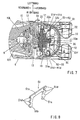
- Fig. 7 and Fig. 8 show a motion converting mechanism 50 according to a third example.
- the motion converting mechanism 50 of the third example is different from the second example described above in a supporting plate 51 having heat dissipating portions 51d.
- the motion converting mechanism 50 is the same as the motion converting mechanism 41 of the second example. Therefore, in FIGS. 7 and 8 , like memers are given the same reference signs as the second example and the description of these members will not be repeated.
- the supporting plate 51 of the third example is a sheet-metal member formed by stamping a steel plate and has a U-shape including left and right vertical support portions 51a and a lateral support portion 51c.
- the heat dissipating portions 51d provided on the left and right vertical supporting portions 51a and 51b are configured differently from the heat dissipating portions 45e and 45d of the second example.
- edge portions of the left and right vertical support portions 45a and 45b are forwardly bent over the entire length to form the heat dissipating portions 45d and 45e.
- three separate heat dissipating portions 51d protruding laterally are provided in each of the left and right vertical support portions 51a and 51b.
- three rectangular support window portions 52 are formed to extend through each of the left and half housing halves 10L and 10R at positions corresponding to the heat dissipating portions 51d positioned on each of left and right sides.
- the support plate 51 is held to be fixed in position between the left and right housing halves 10L and 10R in a state in which the respective heat dissipating portions 51d are inserted into the supporting window portion 52.
- the heat dissipating portions 51d inserted into the respective supporting window portion 52 are brought into contact with the die-cast aluminum front cover 42.
- the friction heat generated in the supporting plate 51 by the reciprocating motion of the slider 22 is dissipated after being released to the front cover 42 via left and right heat dissipating portions 51d that are six in total. Therefore, the durability of the motion converting mechanism 50 may be enhanced in the same manner as the second example.
- the first to third examples described above may further be modified in various manners.
- the rod 30 having the tool-less type clamping device can be replaced with a rod to which the blade B is fixed by using a screw or the like.
- this configuration can be replaced with a configuration in which the flange portion 20a is omitted, while a support plate similar to the support plate 26 (45, 51) on the front side is added to the rear side, so that the slider 22 is held between the support plates from opposite sides in the thickness direction of the slider 22.
Abstract
Description
- The present invention relates to reciprocating cutting tools, such as hand-held cutting tools called a "jigsaw", and more specifically, to reciprocating cutting tools configured to cut work-pieces by reciprocating blades.
- In general, a jigsaw includes a motion converting mechanism configured to convert a rotation of an electric motor as a drive source into a reciprocating motion of a blade, and a technology relating to this kind of motion converting mechanisms is disclosed in, for example, in
US 2002/0032968A1 (also published as Japanese Patent No.3710697 - The motion converting mechanism is assembled within an aluminum die-cast gear housing cover attached to a front portion of a body housing. The electric motor as a drive source is built in a tool body portion. The motion converting mechanism is configured to transmit the rotary output of the drive motor to a crank disk, cause a guide roller eccentrically attached to the crank disk to engage an angular U-shaped slider supported by the gear housing cover so as to be capable of making a vertical reciprocating motion, cause the guide roller to make an orbital motion in the slider while sliding therein and, using the vertical components of the orbital motion, cause the slider to make a vertical reciprocating motion, thereby causing a rod coupled thereto and the blade (cutting blade) mounted on the rod to make a vertical reciprocating motion.
- The rod is coupled to the slider so as to be pivotable in the fore-and-aft direction with respect to the slider within a small angle, and the blade is pushed forward in a cutting direction by a backup roller. The backup roller is displaced in the fore-and-aft direction by the vertical motion of a cam plate in association with the rotation of the crank disk, so that an efficient cutting work is achieved by causing the blade to make the vertical reciprocating motion (orbital motion) while causing the same to pivot in the fore-and-aft direction.
- However, the jigsaw in the related art described above has the following problems to be improved. In general, the hand-held tools of this type have a housing made of resin with a two-split structure for the purpose reduction in weight and cost. In the jigsaw described above, a resin made two-split housing structure is employed for the tool body portion in many cases. However, the gear housing cover having the motion converting mechanism built therein is formed of die-cast aluminum that is still heavy in weight. Regarding the gear housing cover, for example, since a smooth sliding motion of the guide roller with respect to the slider as well as a smooth vertical motion and a fore-and-aft reciprocating motion of the rod are required, related components are required to be assembled with a high degree of accuracy. Consequently, in the related art, the die-cast aluminum housing cover which can easily secure the accuracy by machining is attached to the inside of the body housing, and a pair of left and right guide rails configured to support the slider so as to be capable of making a vertical reciprocating motion are attached to the gear housing cover with a high degree of accuracy. Therefore, the presence of the gear housing cover and the pair of left and right guide rails, which occupy large weight distribution ratios because of being formed of metal, makes the weight reduction of the entire jigsaw difficult.
- Therefore, there is a need in the art for a reciprocating cutting tool that can be configured to have a lightweight construction.
- According to the present teaching, a reciprocating cutting tool includes a motion converting mechanism configured to convert rotation of a rotary member into a reciprocating motion of a slider coupled to a rod capable of mounting a blade thereon. The reciprocating cutting tool further includes a slider support mechanism including a first support mechanism and a second support mechanism disposed at different positions along a reciprocating direction of the slider and each supporting the slider such that the slider can move in the reciprocating direction. The first support mechanism includes a first member and a second member disposed on opposite sides of the slider in a holding direction perpendicular to the reciprocating direction and each slidably contacting the slider.
- Additional objects, features, and advantages, of the present invention will be readily understood after reading the following detailed description together with the claims and the accompanying drawings, in which:
-
FIG. 1 is a side view of an entire jigsaw according to a first example; -
FIG. 2 is a vertical cross-sectional view of a front portion of the jigsaw and showing a motion converting mechanism of the first example; -
FIG 3 is a horizontal sectional view of the motion converting mechanism taken along line III-III inFig. 2 ; -
FIG. 4 is an exploded perspective view of the motion converting mechanism; -
FIG. 5 is a horizontal sectional view of a front portion of a jigsaw and showing a motion converting mechanism according to a second example; -
FIG. 6 is a perspective view of a support plate of the second example; -
FIG. 7 is a horizontal sectional view of a front portion of a jigsaw and showing a motion converting mechanism according to a third example; and -
FIG 8 is a perspective view of a supporting plate of the third embodiment. - Each of the additional features and teachings disclosed above and below may be utilized separately or in conjunction with other features and teachings to provide improved reciprocating cutting tools. Representative examples of the present invention, which examples utilize many of these additional features and teachings both separately and in conjunction with one another, will now be described in detail with reference to the attached drawings. This detailed description is merely intended to teach a person of skill in the art further details for practicing preferred aspects of the present teachings and is not intended to limit the scope of the invention. Only the claims define the scope of the claimed invention. Therefore, combinations of features and steps disclosed in the following detailed description may not be necessary to practice the invention in the broadest sense, and are instead taught merely to particularly describe representative examples of the invention. Moreover, various features of the representative examples and the dependent claims may be combined in ways that are not specifically enumerated in order to provide additional useful examples of the present teachings. Various examples will now be described with reference to the drawings.
- In one example, a reciprocating cutting tool includes a body housing, an electric motor and a motion converting mechanism configured to convert rotation of the electric motor into a reciprocating motion of a rod having a blade mounted thereon. The electric motor and the motion converting mechanism are disposed within the body housing. The motion converting mechanism includes a crank disk configured to be rotated by the electric motor, a guide member eccentrically mounted to the crank disk and configured to make an orbital motion by the rotation of the crank disk, and a slider capable of reciprocating in a reciprocating direction of the rod and configured to transmit to the rod a component of the orbital motion of the guide member in the reciprocating direction to cause the reciprocating motion of the rod. The slider has a flat plate shape and includes a guide plate portion and a support plate portion. The guide plate portion has a guide groove portion engaging the guide member. The support plate portion extends in the reciprocating direction of the rod. The guide plate portion is held from opposite sides in a direction of thickness of the flat plate shape, so that the guide plate portion is prevented from moving in the direction of thickness. The support plate portion is inserted into a support hole formed in a slider guide provided on the body housing, so that the support plate portion is prevented from moving in a direction perpendicular to a plane of the support plate portion.
- Because the slider is held from opposite sides in the thickness direction without using a pair of left and right guide rails that are used in the known device. In addition, the movement of the support plate portion in the direction parallel to the plane of the support plate portion is prevented by inserting the support plate portion into the support hole of the slider guide. Therefore, the slider can be supported so as to be capable of making a reciprocating motion without using the pair of left and right guide rails and a gear housing for assembling the same with a high degree of accuracy of the known device, whereby reduction in weight of the motion converting mechanism and hence of the reciprocating cutting tool is achieved.
- The guide plate portion of the slider may be held from opposite sides by a flange portion provided on the guide member and a support plate mounted on the body housing. With this arrangement, it is possible to downsize the motion converting mechanism in the thickness direction.
- The support plate may have a flat plate shape formed into an inverted U-shape and may include a pair of left and right vertical support portions and a lateral support portion connecting upper portions of the vertical support portions. Opposite end portions of the guide plate portion of the slider are in sliding contact with the left and right vertical support portions, and the support plate portion of the slider is in sliding contact with the lateral support portion, With this arrangement, reduction in weight of the supporting plate is achieved while ensuring a required and sufficient area for supporting the slider.
- The slider guide may be movable in the thickness direction of the slider to allow movement of the slider in the thickness direction. Therefore, a potential accumulative error in machining the members which constitute the motion converting mechanism and a potential assembling error in assembling these members with the body housing can be absorbed, whereby the smooth reciprocating action of the slider can be easily ensured.
- The body housing may be made of synthetic resin and may be split into left and right housing halves with respect to a plane extending in a longitudinal direction of the tool. The guide plate portion of the slider may be held in the thickness direction between the guide member and a support plate attached between the left and right housing halves. The cutting tool may further include a cover made of die-cast aluminum and attached to an outer surface of the body housing. The support plate contacts the cover, so that heat produced at the support plate is dissipated via the cover. With this arrangement, because the support plate for holding the slider in the thickness direction is mounted between the left and right housing halves, it is possible to easily perform the assembling operation of the support plate. In addition, the friction heat that may be generated at the supporting plate due to the reciprocating motion of the slider is efficiently released to the die-cast aluminum cover to achieve heat dissipation, and hence the durability of the motion converting mechanism is improved.
- Referring now to
Fig. 1 to Fig. 8 , an example will be described. In this embodiment, a jigsaw 1 is exemplified as an example of a reciprocating cutting tool.Fig. 1 shows an appearance of the entire jigsaw 1. The jigsaw 1 generally includes atool body portion 2 having anelectric motor 6 built in aresin body housing 10, amotion converting mechanism 3 assembled within a front portion of thebody housing 10, a loop-shaped handle portion 4 provided integrally with an upper portion of thebody housing 10, and abase 5 that supports thebody housing 10 and extends along the lower portion thereof. - In
Fig. 1 , a user is positioned on the left side of the jigsaw 1. In a state of holding the handle portion 4 and placing thebase 5 on an upper surface of a workpiece W, the user may perform a cutting operation by moving the jigsaw 1 forward (rightward inFig. 1 as indicated by an outline arrow) for causing a blade B to cut into the workpiece W. In the following description, the fore-and-aft directions of members and configurations ate defined such that the side of a direction for moving the jigsaw I for performing the cutting operation (hereinafter called a "cutting direction") is a front side and the side where the user resides is a rear side. Left and right sides are defined as those as view from the side of the user. - A
switch lever 7 is provided on the side of a lower surface of the handle portion 4. When the user pulls theswitch lever 7 upward with a fingertip(s) of his or her hand holding the handle portion 4, theelectric motor 6 is activated. When theelectric motor 6 is activated, the rotary output therefrom is converted into a vertical reciprocating motion of arod 30 by amotion converting mechanism 3, described later, whereby the blade B makes a vertical reciprocating motion. Apower source cord 9 is drawn into a rear portion of the handle portion 4. Theelectric motor 6 is activated with AC power supplied via thepower source cord 9. - The details of the
motion converting mechanism 3 are given inFig. 2 andFig. 3 . Thebody housing 10 has a structure split into right and left with respect to a vertical plane along a longitudinal direction of the tool (in the forward and rearward direction) and includes left andright housing halves screws 10b after being positioned relative to each other. As shown inFig. 3 , themotion converting mechanism 3 is assembled within the front portion of thebody housing 10 so as to be positioned between front portions of the left andright housing halves - A cooling
fan 8 for producing a flow of air for cooling themotor 6 is attached to an output shaft of theelectric motor 6, and apinion gear 6a is formed on the output shaft as shown inFig. 2 . Thepinion gear 6a is meshed with adrive gear portion 16 formed on the periphery of acrank disk 11. Asupport base portion 12 is disposed between the left andright housing halves Fig. 3 , in this example, thesupport base portion 12 is fixed to theright housing half 10R by a fixingscrew 13. The output shaft of theelectric motor 6 is rotatably supported by thesupport base portion 12 via abearing 14. Thecrank disk 11 is rotatably supported by asupport shaft 15 provided on thesupport base portion 12. As theelectric motor 6 rotates, thecrank disk 11 is rotated about the supportingshaft 15 via thedrive gear portion 16. - A
guide member 20 is supported on a front surface of thecrank disk 11. Theguide member 20 is rotatably supported by asupport shaft 21. Thesupport shaft 21 is offset by a certain distance from thesupport shaft 15. Therefore, when thecrank disk 11 is rotated by theelectric motor 6, theguide member 20 makes an orbital motion about the supportingshaft 15. - The
guide member 20 is a cylindrical roller, and is provided with aflange portion 20a at a rear portion thereof. Theguide member 20 is inserted into aguide groove portion 22a of aslider 22. As shown inFig. 4 , theslider 22 has a shape like a T-shaped flat plate and includes aguide plate portion 22b elongated in the lateral direction (left and right direction) and asupport plate portion 22c elongated in the vertical direction. In this example, a member manufactured by a sheet-metal working process (so-called, a sheet-metal member) is employed as theslider 22. Therefore, theslider 22 can be manufactured at a low cost by stamping a steel plate or the like. Aguide groove portion 22a is formed on theguide plate portion 22b. Theguide groove portion 22a is configured as a slot elongated in the lateral direction. Theguide groove portion 22a is formed to have a widthwise dimension which allows theguide member 20 to be displaced leftward and rightward without rattling. - A
support plate portion 22c extends upward from a center of an upper portion of theguide plate portion 22b. Arelief hole 22d for reducing the weight is provided through the supportingplate portion 22c in the thickness direction thereof. Thesupport plate portion 22c has a flat plate shape having a rectangular cross section. Thesupport plate portion 22c is inserted into asupport hole 25a of aslider guide 25 from below. Theslider guide 25 is attached between the left andright housing halves support hole 25a has a rectangular shape which allows thesupport plate portion 22c of theslider 22 to be displaced in the vertical direction without rattling. Because thesupport plate portion 22c is inserted into thesquare support hole 25a, the rattling movement mainly in the lateral direction (the direction orthogonal to a paper plane ofFig. 2 ) is restricted. - The
slider guide 25 is supported between the left andright housing halves slider guide 25 can rotate about an axis extending in the lateral direction orthogonal to the paper plane ofFig. 2 . As theslider guide 25 is rotatable about the axis in the lateral direction, movement or vibration in the forward and rearward direction of thesupport plate portion 22c and hence theslider 22 is absorbed, and an accumulative error with respect to thebody housing 10, which may be generated in machining or assembling of the related components, can be absorbed. - A
support plate 26 slidably contacts a front surface of theslider 22. As shown inFig. 4 , thesupport plate 26 is formed into an inverted U-shape including left and rightvertical support portions lateral support portion 26c connecting upper end portions of the left and rightvertical support portions Fig. 3 , thesupport plate 26 is fixed by inserting the left and rightvertical support portions grooves 10a provided in the left andright housing halves guide plate portion 22b of theslider 22 are in sliding contact with the left and rightvertical support portions support plate 26, respectively. More specifically, the left and rightvertical support portions guide plate portion 22b in a state of not closing theguide groove portion 22a. Thesupport plate portion 22c of theslider 22 is in sliding contact with thelateral support portion 26c of thesupport plate 26. - The
flange portion 20a of theguide member 20 inserted into theguide groove portion 22a is in sliding contact with a rear surface of theguide plate portion 22b of theslider 22. In this manner, theguide plate portion 22b of theslider 22 is supported by thesupport plate 26 on the front side and theflange portion 20a on the rear side in a state of being clamped in the thickness direction without rattling in the forward and rearward direction. As described above, theslider 22 is restricted from forward, rearward, leftward and rightward displacements also due to insertion of thesupport plate portion 22c into thesupport hole 25a of theslider guide 25. - A pair of left and right
rod support portions guide plate portion 22b of theslider 22 so as to protrude forward in parallel to each other. Therod support portions respective support holes rod 30 is supported between the left and rightrod support portions rod 30 is supported by theslider 22 so as to be pivotable in the forward and rearward direction by means of asupport hole 30a and asupport shaft 27. Thesupport hole 30a is provided in the upper portion of therod 30. Thesupport shaft 27 is inserted into the support holes 22g and 22h of the left and rightrod support portions rod 30 has a rectangular shaft shape having a rectangular cross section, and is restricted at the upper portion thereof from rattling in the upward, downward, leftward and rightward directions and is also restricted from rotating about its axis by being held between the left and rightrod supporting portions rod 30 is protruded downward through asupport hole 38a formed in abush 38 attached to thebody housing 10. Thesupport hole 38a of thebush 38 is formed into a rectangular hole having such a size that can restrict rattling in the lateral direction while allowing a pivotal motion of therod 30 in the forward and rearward direction. - A
clamp device 31 for mounting the blade B is provided at a lower portion of therod 30 protruding from thebody housing 10. The clampingdevice 31 may be a known clamp device and will not be described in detail. In this example, theclamp device 31 is a so-called tool-less type clamp device that allows easy mounting and removing of the blade B without using a specific tool. Theclamp device 31 includes anoperation sleeve 31a biased by a spring in one direction with respect to the rotational direction about the axis of therod 30. By rotating theoperation sleeve 31a against the biasing force of the spring, the blade B can be easily removed. On the other hand, by rotating theoperation sleeve 31a in the opposite direction by using the biasing force of the spring, the blade B inserted from below can be locked in a mounted state. - As the
crank disk 11 rotates by the activation of theelectric motor 6, theguide member 20 makes an orbital motion about the supportingshaft 15. As theguide member 20 engaged with theguide groove portion 22a of theslider 22 makes the orbital motion, the lateral component of the motion thereof is absorbed due to movement along theguide groove portion 22a, while the vertical component of the motion causes theslider 22 to make a vertical reciprocating motion. As theslider 22 makes the vertical reciprocating motion, therod 30 makes a reciprocating motion integrally therewith, whereby the blade B makes a vertical reciprocating motion to achieve the cutting work. - As shown in
Fig. 2 , thecrank disk 11 includes a firstcam plate portion 11a and a secondcam plate portion 11b provided integrally with the rear surface of thecrank disk 11 at positions adjacent thereto in the thickness direction of thecrank disk 11. A flat-plate-shapedbalancer 32 is supported on the rear surface side of thecrank disk 11 so as to be capable of making a vertical reciprocating motion. The firstcam plate portion 11a is engaged with thebalancer 32. Thebalancer 32 makes a vertical reciprocating motion by the rotation of the firstcam plate portion 11a rotating with thecrank disk 11. Thebalancer 32 makes a vertical motion in the direction opposite to the direction of vertical motion of therod 30 and the blade B. Thebalancer 32 functions as a balance weight for balancing in weight of themotion converting mechanism 3, so that potential vibrations and noises of the jigsaw 1 are reduced by thebalancer 32. - An
actuation plate 33 having a flat plate shape similar to thebalancer 32 is supported on the rear surface side of thebalancer 32 so as to be capable of making a vertical reciprocating motion. The secondcam plate portion 11b is engaged with theactuation plate 33. As thecrank disk 11 rotates theactuation plate 33 makes a vertical reciprocating motion in the same direction as thebalancer 32 by a stroke smaller than that of thebalancer 32. Aroller holder 34 is provided below theactuation plate 33 so as to be pivotable in the vertical direction about asupport shaft 35. Abackup roller 36 is rotatably supported at a front end portion of theroller holder 34. Thebackup roller 36 is in contact with a rear edge of the blade B. - A lower end portion of the
actuation plate 33 is in abutment with arear portion 34a of theroller holder 34 from above. As theactuation plate 33 moves downward, therear portion 34a of theroller holder 34 is pushed downward. Therefore, theroller holder 34 pivots about thesupport shaft 35 counterclockwise inFig. 2 , whereby thebackup roller 36 is displaced forwardly and obliquely upward to push the blade B forward. Because the blade B is pushed forward by theback roller 36, a force for cutting the workpiece W is applied to the blade B. As theactuation plate 33 moves upward, thebackup roller 36 returns backward and obliquely downward by being pushed by the blade B. In this manner, by pushing the blade B periodically forward by thebackup roller 36 when the blade B moves upward, the blade B can make a orbital motion (a reciprocating motion in the vertical direction while pivoting slightly in the forward and rearward direction), whereby an efficient cutting work can be made by the applied to the blade B.Fig. 2 shows a state in which therod 30 and the blade B are returned to the upper stroke end, and thebalancer 32 is positioned at a lower stroke end, and theactuation plate 33 is moved to the lower stroke end so that thebackup roller 36 is displaced forwardly and obliquely upward. - Since a
semi-circular arc portion 37a of a switchingrod 37 is in abutment with therear portion 34a of theroller holder 34 from above, in the state shown inFig. 2 , theroller holder 34 is locked to a position where theroller holder 34 is rotated counterclockwise and pushes theroller 36 against the rear edge of the blade B. When the switchingrod 37 is rotated by approximately 90° counterclockwise inFig. 2 , a relief portion 37b of the switchingrod 37 is opposed to therear portion 34a of theroller holder 34, so that a state in which theroller holder 34 is rotatable clockwise inFig. 2 is resulted. Therefore, in this state, by the upward displacement of theactuation plate 33, thebackup roller 36 is pushed by the blade B and is displaced rearward and obliquely downward. - A
dust cover 40 having a semi-circular shape in cross section and formed of transparent resin is supported on the front portion of thebody housing 10 so as to be movable in the vertical direction.Fig. 1 andFig. 2 show a state in which thedust cover 40 has been retracted upward. By moving thedust cover 40 downward to a position for shielding the front and left and right sides of the blade B, visibility of the cutting portion is secured, and cutting chips are prevented from scattering around. Aguard bar 39 is mounted to the front portion of thebody housing 10 and protrudes downward in a manner like a U-shape so as to be positioned in front of the blade B. - According to the
motion converting mechanism 3 of this example configured as described above, the slider support structure for vertically reciprocally supporting theslider 22 is configured to reciprocally movably hold theslider 22 between theflange portion 20a of theguide member 20 and thesupport plate 26 in the thickness direction, and therefore, the left and right guide rails forming the U-shape in the known device are no longer necessary. Since the left and right guide rails for reciprocally movably supporting the slider can be omitted, it is no longer necessary to provide rail mounting bases that are necessary for assembling the guide rails to each other with a high degree of accuracy Thus, the gear housing cover of the known device can be omitted. - In the known device, due to the need of providing the rail mounting bases for mounting the left and right guide rails on the housing with a high degree of accuracy, for example, a die-cast aluminum (metallic) gear housing cover is necessary, and hence the weight reduction of the jigsaw is difficult. In contrast, according to the slider supporting structure of the above example, the left and right guide rails and the metallic gear housing cover provided with the rail mounting bases can be omitted, and therefore, the
motion converting mechanism 3 is lightweight, and hence, the jigsaw 1 is light weight. In addition, the assembling operation of the jigsaw 1 as well as themotion converting mechanism 3 can be easily efficiently performed. - Further, since the
slider 22 which supports therod 30 is supported in the state of being held between theflange portion 20a of theguide member 20 and thesupport plate 26 in the thickness direction, therod 30 is prevented from being bent to be angled at a joint portion (support shaft 27) to theslider 22 due to a cutting resistance or the like applied to the blade B by the cutting work, and hence another problem does not occur by the omission of the left and right guide rails of the known. - In addition, since the
slider 22 is formed of a flat-plate-shaped sheet-metal member, themotion converting mechanism 3 can be downsized in the forward and rearward direction (thickness direction of the slider 22) in comparison with the U-shaped slider of the known device. - Since the configuration in which the
slider 22 is held by using theflange portion 20a of theguide member 20 is employed, in this point as well, it is possible to achieve reduction in the number of components and downsizing of the construction in comparison with the configuration in which an additional holding member is provided, Thesupport plate 26 for holding the front side of theslider 22 is formed into a U-shape including the left and rightvertical support portions lateral support portion 26c, and therefore, it is configured to slidably contact theslider 22 over a minimum range required for supporting theslider 22. Hence, it is possible to achieve reduction in weight of the supportingplate 26, and therefore, it is possible to achieve reduction in weight and downsizing of themotion converting mechanism 3. - In addition, the
slider guide 25 configured to support thesupport plate portion 22c of theslider 22 is supported so as to be rotatable about the axis extending in the direction of a plane of theslider 22, whereby the displacement of theslider 22 in the forward and rearward direction is arrowed. Therefore, it is possible to adsorb a potential accumulative error in the machining accuracy and a potential accumulative error in assembling the related members which constitute themotion converting mechanism 3, so that smooth reciprocating motions of therod 30 and the blade B can be achieved. - Various modifications may be made to the first example described above.
Fig. 5 shows amotion converting mechanism 41 according to a second example. Themotion converting mechanism 41 of the second example includes a die-castaluminum front cover 42 instead of the transparentresin dust cover 40 in the first example. A cover thinner and lighter than the gear housing cover in the known device is employed as thefront cover 42. Thefront cover 42 provides robustness of the front portion of thebody housing 10. - In the second example, a
support plate 45 is employed instead of thesupport plate 26 of the first example. As shown inFig. 5 , theslider 22 is supported so as to be capable of making a vertical reciprocating motion by being held between thesupport plate 45 and theflange portion 20a of theguide member 20 in the thickness direction of theslider 22, and in this respect, a principal function of thesupport plate 45 is the same as thesupport plate 26 of the first example. - The
support plate 45 of the second example is shown separately inFig. 6 . Thesupport plate 45 has an inverted U-shape having a pair of left and rightvertical support portions lateral support portion 45c connecting between upper portions of thevertical support portions support plate 45 has a shape similar to thesupport plate 26 of the first example and theportions support plate 26. - The
support plate 45 of the second example is different from the supportingplate 26 of the first example in thatheat dissipating portions vertical support portions support plate 45, a sheet-metal member manufactured by stamping a steel plate is used, and the left and rightheat dissipating portions vertical support portions - As shown in
Fig. 5 , the left and rightheat dissipating portions support plate 45 are fitted intosupport window portions right housing halves support plate 45 is fixed in position with respect to the vertical direction and the forward and rearward direction. In addition, the left and rightheat dissipating portions support window portions aluminum front cover 42. Therefore, heat that may be generated in thesupport plate 45 by the friction due to sliding contact of theslider 22 for the vertical reciprocating motion can be released to thefront cover 42 via theheat dissipating portions motion converting mechanism 41 can be enhanced. - In this manner, in the second example, due to omission of the gear housing cover in the known device, reduction in weight of the
motion converting mechanism 41 is achieved and, by using the die-castaluminum front cover 42 instead of the resin-madedust cover 40 of the first example, robustness of the front portion of thebody housing 10 and the heat dissipating properties of themotion converting mechanism 41 are enhanced, and hence the durability is improved. -
Fig. 7 and Fig. 8 show amotion converting mechanism 50 according to a third example. Themotion converting mechanism 50 of the third example is different from the second example described above in a supportingplate 51 havingheat dissipating portions 51d. In other respect, themotion converting mechanism 50 is the same as themotion converting mechanism 41 of the second example. Therefore, inFIGS. 7 and 8 , like memers are given the same reference signs as the second example and the description of these members will not be repeated. - As shown in
Fig. 8 , similar to the first and second examples, the supportingplate 51 of the third example is a sheet-metal member formed by stamping a steel plate and has a U-shape including left and rightvertical support portions 51a and alateral support portion 51c. Theheat dissipating portions 51d provided on the left and right vertical supportingportions heat dissipating portions vertical support portions heat dissipating portions heat dissipating portions 51d protruding laterally are provided in each of the left and rightvertical support portions - In the case of the third example, three rectangular
support window portions 52 are formed to extend through each of the left andhalf housing halves heat dissipating portions 51d positioned on each of left and right sides. As shown inFig. 7 , thesupport plate 51 is held to be fixed in position between the left andright housing halves heat dissipating portions 51d are inserted into the supportingwindow portion 52. Theheat dissipating portions 51d inserted into the respective supportingwindow portion 52 are brought into contact with the die-castaluminum front cover 42. - The friction heat generated in the supporting
plate 51 by the reciprocating motion of theslider 22 is dissipated after being released to thefront cover 42 via left and rightheat dissipating portions 51d that are six in total. Therefore, the durability of themotion converting mechanism 50 may be enhanced in the same manner as the second example. - The first to third examples described above may further be modified in various manners. For example, the
rod 30 having the tool-less type clamping device can be replaced with a rod to which the blade B is fixed by using a screw or the like. - Although the configuration in which the
flange portion 20a is provided on theguide member 20, and theslider 22 is held between theflange portion 20a and the support plate 26 (45, 51) in the thickness direction has been used in the first to third examples, this configuration can be replaced with a configuration in which theflange portion 20a is omitted, while a support plate similar to the support plate 26 (45, 51) on the front side is added to the rear side, so that theslider 22 is held between the support plates from opposite sides in the thickness direction of theslider 22. - In addition, although a sheet-metal member formed by stamping a steel plate is used for the
slider 22 in the first to third examples and a sheet-member is also used for each of thesupport plates slider 22 and thesupport plates
It is explicitly stated that all features disclosed in the description and/or the claims are intended to be disclosed separately and independently from each other for the purpose of original disclosure as well as for the purpose of restricting the claimed invention independent of the composition of the features in the embodiments and/or the claims. It is explicitly stated that all value ranges or indications of groups of entities disclose every possible intermediate value or intermediate entity for the purpose of original disclosure as well as for the purpose of restricting the claimed invention, in particular as limits of value ranges.
Claims (14)
- A reciprocating cutting tool (1) comprising:a motion converting mechanism (3; 41; 50) configured to convert rotation of a rotary member (11) into a reciprocating motion of a slider (22) coupled to a rod (30) capable of mounting a blade (B) thereon, anda slider support mechanism comprising a first support mechanism (20, 26; 20; 45; 20; 51) and a second support mechanism (25) disposed at different positions along a reciprocating direction of the slider (22) and each supporting the slider (22) such that the slider (22) can move in the reciprocating direction; wherein:the first support mechanism (20, 26; 20; 45; 20; 51) includes a first member (26; 45; 51) and a second member (20) disposed on opposite sides of the slider (22) in a holding direction perpendicular to the reciprocating direction and each slidably contacting the slider (22).
- The reciprocating cutting tool (I) according to claim 1, wherein;
the first member (26; 45; 51) has a first surface slidably contacting the slider (22) and extending within a fist plane parallel to the reciprocating direction; and
the second member (20) has a second surface slidably contacting the slider (22) and extending within a second plane parallel to the first plane. - The reciprocating cutting tool (1) according to claim 1 or 2, wherein:the second support mechanism comprises a slider guide (25) having a support hole (25a) vertically slidably receiving the slider (22).
- The reciprocating cutting tool (1) according to any one of claims 1 to 3, wherein the slider (22) has a configuration of a plate having a thickness in the holding direction.
- The reciprocating cutting device according to any one of claims 1 to 4, wherein the first member (26; 45; 51) has a configuration of a plate having a thickness in the holding direction.
- The reciprocating cutting device according to any one of claims 1 to 5, further comprising a body housing (10) accommodating the motion converting mechanism (3; 41; 50), wherein the first member (26; 45; 51) is fixed in position relative to the body housing (10) and the second member (20) is coupled to the rotary member (11) and movable relative to the body housing (10).
- The reciprocating cutting device according to claim any one of claims 1 to 6, wherein the second member is a guide member (20) coupled to the rotary member (11) and making an orbital motion as the rotary member (11) rotates.
- The reciprocating cutting tool (1) according to claim 1, further comprising:a body housing (10); andan electric motor (6) rotatably driving the rotary member (11); wherein:the electric motor (6) and the reciprocating motion converting mechanism (3; 41; 50) are disposed within the body housing (10),the rotary member is a crank disk (11) configured to be rotated by the electric motor (6),the second member of the first support mechanism (20, 26; 20; 45; 20; 51) is a guide member (20) eccentrically mounted to the crank disk (11) and configured to make an orbital motion by the rotation of the crank disk (11), so that the slider (22) reciprocates in the reciprocating direction of the rod (30) and configured to transmit to the rod (30) a component of the orbital motion of the guide member (20) in the reciprocating direction to cause the reciprocating motion of the rod (30), andthe slider (22) has a flat plate shape and includes a guide plate portion (22b) and a support plate portion (22c);the guide plate portion (22b) has a guide groove portion (22a) engaging the guide member (20); the holding direction is a direction of thickness of the flat plate shape of the slider (22) and the guide plate portion (22b) is held from opposite sides in the direction of thickness of the flat plate shape by the first support mechanism (20, 26; 20; 45; 20; 51), so that the guide plate portion (22b) is prevented from moving in the direction of thickness;the second support mechanism (25) includes a slider guide (25) provided on the body housing (10) and having a support hole (25a); andthe support plate portion (22c) is inserted into the support hole (25a), so that the support plate portion (22c) is prevented from moving in a direction perpendicular to a plane of the support plate portion (22c).
- The reciprocating cutting tool (1) as in claim 8, wherein the first member of the first support mechanism (20, 26; 20; 45; 20; 51) is a support plate (26; 45; 51) mounted on the body housing (10), and the guide plate portion (22b) of the slider (22) is held from opposite sides by a flange portion (20a) provided on the guide member (20) and the support plate (26; 45; 51).
- The reciprocating cutting tool (1) as in claims 9, wherein the support plate (26; 45; 51) has a flat plate shape formed into an inverted U-shape and includes a pair of left and right vertical support portions (26a, 26b; 45a, 45b; 51a, 51b) and a lateral support portion (26c; 45c; 51c) connecting upper portions of the vertical support portions, opposite end portions of the guide plate portion (22b) of the slider (22) are in sliding contact with the left and right vertical support portions, and the support plate portion (22c) of the slider (22) is in sliding contact with the lateral support portion.
- The reciprocating cutting tool (1) as in any one of claims 8 to 10, wherein the slider guide (25) is movable in the thickness direction of the slider (22) to allow movement of the slider (22) in the thickness direction.
- The reciprocating cutting tool (1) as in claim 8, wherein the body housing (10) is made of synthetic resin and is split into left: and right housing halves (10L, 10R) with respect to a plane extending in a longitudinal direction of the tool, the guide plate portion (22b) of the slider (22) is held in the thickness direction between the guide member (20) and a support plate (26; 45; 51) attached between the left and right housing halves.
- The reciprocating cutting tool (1) as in claim 12, further comprising a cover (42) made of die-cast aluminum and attached to an outer surface of the body housing (10), wherein the support plate (45; 51) contacts the cover, so that heat produced at the support plate is dissipated via the cover.
- The reciprocating cutting tool (1) as in any one of claims 9 to 11, wherein the body housing (10) is made of synthetic resin and is split into left and right housing halves (10L, 10R) with respect to a plane extending in a longitudinal direction of the tool, the guide plate portion (22b) of the slider (22) is held in the thickness direction between the guide member (20) and the support plate (26; 45; 51) attached between the left and right housing halves.
Applications Claiming Priority (1)
| Application Number | Priority Date | Filing Date | Title |
|---|---|---|---|
| JP2010091246A JP5474642B2 (en) | 2010-04-12 | 2010-04-12 | Reciprocating cutting tool |
Publications (2)
| Publication Number | Publication Date |
|---|---|
| EP2374564A1 true EP2374564A1 (en) | 2011-10-12 |
| EP2374564B1 EP2374564B1 (en) | 2015-02-25 |
Family
ID=44475215
Family Applications (1)
| Application Number | Title | Priority Date | Filing Date |
|---|---|---|---|
| EP11161938.3A Active EP2374564B1 (en) | 2010-04-12 | 2011-04-11 | Reciprocating cutting tools |
Country Status (5)
| Country | Link |
|---|---|
| US (1) | US8813377B2 (en) |
| EP (1) | EP2374564B1 (en) |
| JP (1) | JP5474642B2 (en) |
| CN (1) | CN102211328B (en) |
| RU (1) | RU2547380C2 (en) |
Families Citing this family (10)
| Publication number | Priority date | Publication date | Assignee | Title |
|---|---|---|---|---|
| JP2013123756A (en) * | 2011-12-13 | 2013-06-24 | Makita Corp | Reciprocating tool |
| JP5774504B2 (en) | 2012-01-13 | 2015-09-09 | 株式会社マキタ | Jigsaw |
| DE102013208132A1 (en) * | 2013-05-03 | 2014-11-06 | Robert Bosch Gmbh | Hand tool |
| US9573207B2 (en) * | 2013-05-09 | 2017-02-21 | Makita Corporation | Reciprocating cutting tool |
| CN104209586B (en) * | 2013-05-29 | 2018-02-02 | 博世电动工具(中国)有限公司 | Electric tool |
| CN104339330B (en) * | 2013-08-08 | 2016-11-02 | 宝时得机械(张家港)有限公司 | Reciprocating power tool |
| CN105328265A (en) * | 2014-06-04 | 2016-02-17 | 宝时得机械(张家港)有限公司 | Jigsaw |
| CN204075377U (en) * | 2014-08-22 | 2015-01-07 | 宁波黑松工具有限公司 | A kind of novel reciprocating saw |
| US10821617B2 (en) * | 2016-01-14 | 2020-11-03 | Nathan Hitson | Animal shears/clippers |
| WO2018014850A1 (en) * | 2016-07-19 | 2018-01-25 | 苏州宝时得电动工具有限公司 | Reciprocating cutting tool |
Citations (7)
| Publication number | Priority date | Publication date | Assignee | Title |
|---|---|---|---|---|
| JPH0370697B2 (en) | 1982-07-02 | 1991-11-08 | Ciba Geigy | |
| DE10000982A1 (en) * | 1999-03-12 | 2000-09-21 | Hitachi Koki Kk | Saw mechanism for compass saw has motion conversion mechanism for converting shaft rotation into reciprocating rod motion, guide element for moving rod along guide track surface |
| US20010042310A1 (en) * | 2000-05-02 | 2001-11-22 | Roland Steele | Flush cut power saw apparatus |
| US20020032968A1 (en) | 2000-09-19 | 2002-03-21 | Yuji Takahashi | Reciprocating cutting tools |
| EP1232817A2 (en) * | 2001-02-16 | 2002-08-21 | Makita Corporation | Reciprocating power tools |
| US20050109137A1 (en) * | 2003-11-20 | 2005-05-26 | Markus Hartmann | Movement conversion device for a hand-held power tool |
| US20050262710A1 (en) * | 2004-05-28 | 2005-12-01 | Credo Technology Corporation | Anti-rotation drive mechanism for a reciprocating saw |
Family Cites Families (23)
| Publication number | Priority date | Publication date | Assignee | Title |
|---|---|---|---|---|
| US2713271A (en) * | 1951-07-17 | 1955-07-19 | Mall Tool Company | Motion converting means |
| US2961016A (en) * | 1956-08-07 | 1960-11-22 | Walter A Papworth | Portable power reciprocating saw |
| US3863342A (en) * | 1971-09-17 | 1975-02-04 | Rockwell International Corp | Saber saw |
| US4272996A (en) * | 1979-06-19 | 1981-06-16 | Black & Decker Inc. | Scotch yoke having a curved track |
| FR2511925A1 (en) * | 1981-08-31 | 1983-03-04 | Peugeot Aciers Et Outillage | HAND TOOL MACHINE HAVING A CUTTING TOOL, ESPECIALLY A JIGSAW |
| US4628605A (en) * | 1985-06-10 | 1986-12-16 | Porter-Cable Corporation | Orbital bayonet saw |
| DE3683911D1 (en) * | 1986-11-11 | 1992-03-26 | Black & Decker Inc | POWER DRIVEN SAW, ESPECIALLY ELECTRIC DRIVE SAW. |
| US5083376A (en) * | 1988-11-14 | 1992-01-28 | Black & Decker Inc. | Thrust bearing arrangement for a power tool transmission |
| US5212887A (en) * | 1992-03-18 | 1993-05-25 | S-B Power Tool Company | Counterbalanced orbital drive mechanism for saws and the like |
| RU2042506C1 (en) * | 1992-06-30 | 1995-08-27 | Владимир Федорович Трефилов | Jig saw |
| CN2199834Y (en) * | 1994-08-25 | 1995-06-07 | 宁波经济技术开发区中强工具有限公司 | Scroll saw |
| US5479709A (en) * | 1994-10-25 | 1996-01-02 | Lai; Motor | Dust removing device for portable power saw |
| JP3510963B2 (en) * | 1997-06-18 | 2004-03-29 | 株式会社マキタ | Jigsaw |
| DE10045598B4 (en) | 2000-09-15 | 2014-03-20 | Andreas Stihl Ag & Co. | Guide tube for a hand-held implement |
| GB2380159A (en) * | 2001-09-29 | 2003-04-02 | Black & Decker Inc | Power tool |
| GB2393934A (en) * | 2002-10-07 | 2004-04-14 | Black & Decker Inc | A reciprocating saw with two eccentrics |
| DE10259565A1 (en) * | 2002-12-19 | 2004-07-01 | Hilti Ag | Pendulum stroke rod bearing for power saw has bearing regions supporting motion setter located in bearing housing part |
| US7234243B2 (en) * | 2003-06-25 | 2007-06-26 | Credo Technology Corporation | Reciprocating cutting tool with orbital action |
| CN2671742Y (en) * | 2004-01-12 | 2005-01-19 | 苏州宝时得电动工具有限公司 | Bias reciprocating mechanism of electric knife and saw |
| RU55324U1 (en) * | 2006-03-13 | 2006-08-10 | Общество с ограниченной ответственностью "Инструментальная компания ЭНКОР" | TABLE ELECTRIC Jigsaw |
| DE102006031513A1 (en) * | 2006-07-07 | 2008-01-17 | Robert Bosch Gmbh | Hand tool, in particular hand saw |
| US9827623B2 (en) * | 2007-09-21 | 2017-11-28 | Black & Decker Inc. | Control of reciprocation speed and orbital magnitude of a jigsaw with a plurality of material and/or task descriptive icons |
| DE102008002678A1 (en) * | 2008-06-26 | 2009-12-31 | Robert Bosch Gmbh | hand-held jigsaw |
-
2010
- 2010-04-12 JP JP2010091246A patent/JP5474642B2/en active Active
-
2011
- 2011-01-26 CN CN201110031428.9A patent/CN102211328B/en active Active
- 2011-04-11 RU RU2011114105/02A patent/RU2547380C2/en active
- 2011-04-11 EP EP11161938.3A patent/EP2374564B1/en active Active
- 2011-04-11 US US13/084,103 patent/US8813377B2/en active Active
Patent Citations (7)
| Publication number | Priority date | Publication date | Assignee | Title |
|---|---|---|---|---|
| JPH0370697B2 (en) | 1982-07-02 | 1991-11-08 | Ciba Geigy | |
| DE10000982A1 (en) * | 1999-03-12 | 2000-09-21 | Hitachi Koki Kk | Saw mechanism for compass saw has motion conversion mechanism for converting shaft rotation into reciprocating rod motion, guide element for moving rod along guide track surface |
| US20010042310A1 (en) * | 2000-05-02 | 2001-11-22 | Roland Steele | Flush cut power saw apparatus |
| US20020032968A1 (en) | 2000-09-19 | 2002-03-21 | Yuji Takahashi | Reciprocating cutting tools |
| EP1232817A2 (en) * | 2001-02-16 | 2002-08-21 | Makita Corporation | Reciprocating power tools |
| US20050109137A1 (en) * | 2003-11-20 | 2005-05-26 | Markus Hartmann | Movement conversion device for a hand-held power tool |
| US20050262710A1 (en) * | 2004-05-28 | 2005-12-01 | Credo Technology Corporation | Anti-rotation drive mechanism for a reciprocating saw |
Also Published As
| Publication number | Publication date |
|---|---|
| RU2011114105A (en) | 2012-10-20 |
| RU2547380C2 (en) | 2015-04-10 |
| US8813377B2 (en) | 2014-08-26 |
| CN102211328A (en) | 2011-10-12 |
| JP5474642B2 (en) | 2014-04-16 |
| JP2011218501A (en) | 2011-11-04 |
| EP2374564B1 (en) | 2015-02-25 |
| US20110247223A1 (en) | 2011-10-13 |
| CN102211328B (en) | 2014-03-26 |
Similar Documents
| Publication | Publication Date | Title |
|---|---|---|
| EP2374564B1 (en) | Reciprocating cutting tools | |
| EP1188505B1 (en) | Reciprocating cutting tools | |
| EP2090393B1 (en) | Reciprocating power tool | |
| US7254892B2 (en) | Support mechanism for a reciprocating tool | |
| US20200070265A1 (en) | Power Tool | |
| US9573207B2 (en) | Reciprocating cutting tool | |
| EP1295662A1 (en) | Reciprocating saw with flush blade | |
| AU2013202470A1 (en) | Multi tool saw | |
| WO1998007544A1 (en) | Reciprocating saw with rocker motion | |
| JP7103002B2 (en) | Cutting machine | |
| US20110023678A1 (en) | Miter saw with increased cutting capacity | |
| US20170157689A1 (en) | Reciprocating Tool with Linear Guides | |
| JP6375878B2 (en) | Reciprocating tool | |
| EP1514655B1 (en) | A shoe assembly for a reciprocating tool | |
| JP2019005920A (en) | Adapter for ruler | |
| EP3750656A1 (en) | Reciprocating saw | |
| JP6451220B2 (en) | Reciprocating tool | |
| JP2005161439A (en) | Saw device | |
| WO2003086692A1 (en) | Drive mechanism for reciprocating tool, and reciprocating tool including such mechanism |
Legal Events
| Date | Code | Title | Description |
|---|---|---|---|
| PUAI | Public reference made under article 153(3) epc to a published international application that has entered the european phase |
Free format text: ORIGINAL CODE: 0009012 |
|
| AK | Designated contracting states |
Kind code of ref document: A1 Designated state(s): AL AT BE BG CH CY CZ DE DK EE ES FI FR GB GR HR HU IE IS IT LI LT LU LV MC MK MT NL NO PL PT RO RS SE SI SK SM TR |
|
| AX | Request for extension of the european patent |
Extension state: BA ME |
|
| 17P | Request for examination filed |
Effective date: 20120411 |
|
| GRAP | Despatch of communication of intention to grant a patent |
Free format text: ORIGINAL CODE: EPIDOSNIGR1 |
|
| INTG | Intention to grant announced |
Effective date: 20140827 |
|
| GRAS | Grant fee paid |
Free format text: ORIGINAL CODE: EPIDOSNIGR3 |
|
| GRAA | (expected) grant |
Free format text: ORIGINAL CODE: 0009210 |
|
| RAP1 | Party data changed (applicant data changed or rights of an application transferred) |
Owner name: MAKITA CORPORATION |
|
| AK | Designated contracting states |
Kind code of ref document: B1 Designated state(s): AL AT BE BG CH CY CZ DE DK EE ES FI FR GB GR HR HU IE IS IT LI LT LU LV MC MK MT NL NO PL PT RO RS SE SI SK SM TR |
|
| REG | Reference to a national code |
Ref country code: GB Ref legal event code: FG4D |
|
| REG | Reference to a national code |
Ref country code: CH Ref legal event code: EP |
|
| REG | Reference to a national code |
Ref country code: IE Ref legal event code: FG4D |
|
| REG | Reference to a national code |
Ref country code: DE Ref legal event code: R096 Ref document number: 602011013881 Country of ref document: DE Effective date: 20150409 |
|
| REG | Reference to a national code |
Ref country code: AT Ref legal event code: REF Ref document number: 711492 Country of ref document: AT Kind code of ref document: T Effective date: 20150415 |
|
| REG | Reference to a national code |
Ref country code: NL Ref legal event code: VDEP Effective date: 20150225 |
|
| REG | Reference to a national code |
Ref country code: AT Ref legal event code: MK05 Ref document number: 711492 Country of ref document: AT Kind code of ref document: T Effective date: 20150225 |
|
| REG | Reference to a national code |
Ref country code: LT Ref legal event code: MG4D |
|
| PG25 | Lapsed in a contracting state [announced via postgrant information from national office to epo] |
Ref country code: SE Free format text: LAPSE BECAUSE OF FAILURE TO SUBMIT A TRANSLATION OF THE DESCRIPTION OR TO PAY THE FEE WITHIN THE PRESCRIBED TIME-LIMIT Effective date: 20150225 Ref country code: FI Free format text: LAPSE BECAUSE OF FAILURE TO SUBMIT A TRANSLATION OF THE DESCRIPTION OR TO PAY THE FEE WITHIN THE PRESCRIBED TIME-LIMIT Effective date: 20150225 Ref country code: ES Free format text: LAPSE BECAUSE OF FAILURE TO SUBMIT A TRANSLATION OF THE DESCRIPTION OR TO PAY THE FEE WITHIN THE PRESCRIBED TIME-LIMIT Effective date: 20150225 Ref country code: NO Free format text: LAPSE BECAUSE OF FAILURE TO SUBMIT A TRANSLATION OF THE DESCRIPTION OR TO PAY THE FEE WITHIN THE PRESCRIBED TIME-LIMIT Effective date: 20150525 Ref country code: LT Free format text: LAPSE BECAUSE OF FAILURE TO SUBMIT A TRANSLATION OF THE DESCRIPTION OR TO PAY THE FEE WITHIN THE PRESCRIBED TIME-LIMIT Effective date: 20150225 Ref country code: HR Free format text: LAPSE BECAUSE OF FAILURE TO SUBMIT A TRANSLATION OF THE DESCRIPTION OR TO PAY THE FEE WITHIN THE PRESCRIBED TIME-LIMIT Effective date: 20150225 |
|
| PG25 | Lapsed in a contracting state [announced via postgrant information from national office to epo] |
Ref country code: GR Free format text: LAPSE BECAUSE OF FAILURE TO SUBMIT A TRANSLATION OF THE DESCRIPTION OR TO PAY THE FEE WITHIN THE PRESCRIBED TIME-LIMIT Effective date: 20150526 Ref country code: IS Free format text: LAPSE BECAUSE OF FAILURE TO SUBMIT A TRANSLATION OF THE DESCRIPTION OR TO PAY THE FEE WITHIN THE PRESCRIBED TIME-LIMIT Effective date: 20150625 Ref country code: AT Free format text: LAPSE BECAUSE OF FAILURE TO SUBMIT A TRANSLATION OF THE DESCRIPTION OR TO PAY THE FEE WITHIN THE PRESCRIBED TIME-LIMIT Effective date: 20150225 Ref country code: RS Free format text: LAPSE BECAUSE OF FAILURE TO SUBMIT A TRANSLATION OF THE DESCRIPTION OR TO PAY THE FEE WITHIN THE PRESCRIBED TIME-LIMIT Effective date: 20150225 Ref country code: LV Free format text: LAPSE BECAUSE OF FAILURE TO SUBMIT A TRANSLATION OF THE DESCRIPTION OR TO PAY THE FEE WITHIN THE PRESCRIBED TIME-LIMIT Effective date: 20150225 |
|
| PG25 | Lapsed in a contracting state [announced via postgrant information from national office to epo] |
Ref country code: NL Free format text: LAPSE BECAUSE OF FAILURE TO SUBMIT A TRANSLATION OF THE DESCRIPTION OR TO PAY THE FEE WITHIN THE PRESCRIBED TIME-LIMIT Effective date: 20150225 |
|
| PG25 | Lapsed in a contracting state [announced via postgrant information from national office to epo] |
Ref country code: CZ Free format text: LAPSE BECAUSE OF FAILURE TO SUBMIT A TRANSLATION OF THE DESCRIPTION OR TO PAY THE FEE WITHIN THE PRESCRIBED TIME-LIMIT Effective date: 20150225 Ref country code: EE Free format text: LAPSE BECAUSE OF FAILURE TO SUBMIT A TRANSLATION OF THE DESCRIPTION OR TO PAY THE FEE WITHIN THE PRESCRIBED TIME-LIMIT Effective date: 20150225 Ref country code: SK Free format text: LAPSE BECAUSE OF FAILURE TO SUBMIT A TRANSLATION OF THE DESCRIPTION OR TO PAY THE FEE WITHIN THE PRESCRIBED TIME-LIMIT Effective date: 20150225 Ref country code: RO Free format text: LAPSE BECAUSE OF FAILURE TO SUBMIT A TRANSLATION OF THE DESCRIPTION OR TO PAY THE FEE WITHIN THE PRESCRIBED TIME-LIMIT Effective date: 20150225 Ref country code: DK Free format text: LAPSE BECAUSE OF FAILURE TO SUBMIT A TRANSLATION OF THE DESCRIPTION OR TO PAY THE FEE WITHIN THE PRESCRIBED TIME-LIMIT Effective date: 20150225 |
|
| REG | Reference to a national code |
Ref country code: DE Ref legal event code: R097 Ref document number: 602011013881 Country of ref document: DE |
|
| PG25 | Lapsed in a contracting state [announced via postgrant information from national office to epo] |
Ref country code: MC Free format text: LAPSE BECAUSE OF FAILURE TO SUBMIT A TRANSLATION OF THE DESCRIPTION OR TO PAY THE FEE WITHIN THE PRESCRIBED TIME-LIMIT Effective date: 20150225 Ref country code: LU Free format text: LAPSE BECAUSE OF FAILURE TO SUBMIT A TRANSLATION OF THE DESCRIPTION OR TO PAY THE FEE WITHIN THE PRESCRIBED TIME-LIMIT Effective date: 20150411 Ref country code: PL Free format text: LAPSE BECAUSE OF FAILURE TO SUBMIT A TRANSLATION OF THE DESCRIPTION OR TO PAY THE FEE WITHIN THE PRESCRIBED TIME-LIMIT Effective date: 20150225 |
|
| REG | Reference to a national code |
Ref country code: CH Ref legal event code: PL |
|
| PG25 | Lapsed in a contracting state [announced via postgrant information from national office to epo] |
Ref country code: IT Free format text: LAPSE BECAUSE OF FAILURE TO SUBMIT A TRANSLATION OF THE DESCRIPTION OR TO PAY THE FEE WITHIN THE PRESCRIBED TIME-LIMIT Effective date: 20150225 |
|
| PLBE | No opposition filed within time limit |
Free format text: ORIGINAL CODE: 0009261 |
|
| STAA | Information on the status of an ep patent application or granted ep patent |
Free format text: STATUS: NO OPPOSITION FILED WITHIN TIME LIMIT |
|
| GBPC | Gb: european patent ceased through non-payment of renewal fee |
Effective date: 20150525 |
|
| REG | Reference to a national code |
Ref country code: IE Ref legal event code: MM4A |
|
| PG25 | Lapsed in a contracting state [announced via postgrant information from national office to epo] |
Ref country code: CH Free format text: LAPSE BECAUSE OF NON-PAYMENT OF DUE FEES Effective date: 20150430 Ref country code: LI Free format text: LAPSE BECAUSE OF NON-PAYMENT OF DUE FEES Effective date: 20150430 |
|
| REG | Reference to a national code |
Ref country code: FR Ref legal event code: ST Effective date: 20151231 |
|
| 26N | No opposition filed |
Effective date: 20151126 |
|
| PG25 | Lapsed in a contracting state [announced via postgrant information from national office to epo] |
Ref country code: SI Free format text: LAPSE BECAUSE OF FAILURE TO SUBMIT A TRANSLATION OF THE DESCRIPTION OR TO PAY THE FEE WITHIN THE PRESCRIBED TIME-LIMIT Effective date: 20150225 Ref country code: FR Free format text: LAPSE BECAUSE OF NON-PAYMENT OF DUE FEES Effective date: 20150430 |
|
| PG25 | Lapsed in a contracting state [announced via postgrant information from national office to epo] |
Ref country code: IE Free format text: LAPSE BECAUSE OF NON-PAYMENT OF DUE FEES Effective date: 20150411 Ref country code: GB Free format text: LAPSE BECAUSE OF NON-PAYMENT OF DUE FEES Effective date: 20150525 |
|
| PG25 | Lapsed in a contracting state [announced via postgrant information from national office to epo] |
Ref country code: BE Free format text: LAPSE BECAUSE OF FAILURE TO SUBMIT A TRANSLATION OF THE DESCRIPTION OR TO PAY THE FEE WITHIN THE PRESCRIBED TIME-LIMIT Effective date: 20150225 |
|
| PG25 | Lapsed in a contracting state [announced via postgrant information from national office to epo] |
Ref country code: MT Free format text: LAPSE BECAUSE OF FAILURE TO SUBMIT A TRANSLATION OF THE DESCRIPTION OR TO PAY THE FEE WITHIN THE PRESCRIBED TIME-LIMIT Effective date: 20150225 |
|
| PG25 | Lapsed in a contracting state [announced via postgrant information from national office to epo] |
Ref country code: SM Free format text: LAPSE BECAUSE OF FAILURE TO SUBMIT A TRANSLATION OF THE DESCRIPTION OR TO PAY THE FEE WITHIN THE PRESCRIBED TIME-LIMIT Effective date: 20150225 Ref country code: HU Free format text: LAPSE BECAUSE OF FAILURE TO SUBMIT A TRANSLATION OF THE DESCRIPTION OR TO PAY THE FEE WITHIN THE PRESCRIBED TIME-LIMIT; INVALID AB INITIO Effective date: 20110411 Ref country code: BG Free format text: LAPSE BECAUSE OF FAILURE TO SUBMIT A TRANSLATION OF THE DESCRIPTION OR TO PAY THE FEE WITHIN THE PRESCRIBED TIME-LIMIT Effective date: 20150225 |
|
| PG25 | Lapsed in a contracting state [announced via postgrant information from national office to epo] |
Ref country code: CY Free format text: LAPSE BECAUSE OF FAILURE TO SUBMIT A TRANSLATION OF THE DESCRIPTION OR TO PAY THE FEE WITHIN THE PRESCRIBED TIME-LIMIT Effective date: 20150225 |
|
| PG25 | Lapsed in a contracting state [announced via postgrant information from national office to epo] |
Ref country code: PT Free format text: LAPSE BECAUSE OF FAILURE TO SUBMIT A TRANSLATION OF THE DESCRIPTION OR TO PAY THE FEE WITHIN THE PRESCRIBED TIME-LIMIT Effective date: 20150625 |
|
| PG25 | Lapsed in a contracting state [announced via postgrant information from national office to epo] |
Ref country code: TR Free format text: LAPSE BECAUSE OF FAILURE TO SUBMIT A TRANSLATION OF THE DESCRIPTION OR TO PAY THE FEE WITHIN THE PRESCRIBED TIME-LIMIT Effective date: 20150225 |
|
| PG25 | Lapsed in a contracting state [announced via postgrant information from national office to epo] |
Ref country code: MK Free format text: LAPSE BECAUSE OF FAILURE TO SUBMIT A TRANSLATION OF THE DESCRIPTION OR TO PAY THE FEE WITHIN THE PRESCRIBED TIME-LIMIT Effective date: 20150225 |
|
| PG25 | Lapsed in a contracting state [announced via postgrant information from national office to epo] |
Ref country code: AL Free format text: LAPSE BECAUSE OF FAILURE TO SUBMIT A TRANSLATION OF THE DESCRIPTION OR TO PAY THE FEE WITHIN THE PRESCRIBED TIME-LIMIT Effective date: 20150225 |
|
| PGFP | Annual fee paid to national office [announced via postgrant information from national office to epo] |
Ref country code: DE Payment date: 20230228 Year of fee payment: 13 |