EP2375469A1 - Secondary battery and a fabrication method thereof - Google Patents
Secondary battery and a fabrication method thereof Download PDFInfo
- Publication number
- EP2375469A1 EP2375469A1 EP11250350A EP11250350A EP2375469A1 EP 2375469 A1 EP2375469 A1 EP 2375469A1 EP 11250350 A EP11250350 A EP 11250350A EP 11250350 A EP11250350 A EP 11250350A EP 2375469 A1 EP2375469 A1 EP 2375469A1
- Authority
- EP
- European Patent Office
- Prior art keywords
- pouch sheet
- pouch
- electrode assembly
- joining step
- sheet
- Prior art date
- Legal status (The legal status is an assumption and is not a legal conclusion. Google has not performed a legal analysis and makes no representation as to the accuracy of the status listed.)
- Granted
Links
Images


Classifications
-
- H—ELECTRICITY
- H01—ELECTRIC ELEMENTS
- H01M—PROCESSES OR MEANS, e.g. BATTERIES, FOR THE DIRECT CONVERSION OF CHEMICAL ENERGY INTO ELECTRICAL ENERGY
- H01M10/00—Secondary cells; Manufacture thereof
- H01M10/04—Construction or manufacture in general
- H01M10/0413—Large-sized flat cells or batteries for motive or stationary systems with plate-like electrodes
-
- H—ELECTRICITY
- H01—ELECTRIC ELEMENTS
- H01M—PROCESSES OR MEANS, e.g. BATTERIES, FOR THE DIRECT CONVERSION OF CHEMICAL ENERGY INTO ELECTRICAL ENERGY
- H01M50/00—Constructional details or processes of manufacture of the non-active parts of electrochemical cells other than fuel cells, e.g. hybrid cells
- H01M50/10—Primary casings, jackets or wrappings of a single cell or a single battery
- H01M50/102—Primary casings, jackets or wrappings of a single cell or a single battery characterised by their shape or physical structure
- H01M50/105—Pouches or flexible bags
-
- H—ELECTRICITY
- H01—ELECTRIC ELEMENTS
- H01M—PROCESSES OR MEANS, e.g. BATTERIES, FOR THE DIRECT CONVERSION OF CHEMICAL ENERGY INTO ELECTRICAL ENERGY
- H01M50/00—Constructional details or processes of manufacture of the non-active parts of electrochemical cells other than fuel cells, e.g. hybrid cells
- H01M50/10—Primary casings, jackets or wrappings of a single cell or a single battery
- H01M50/116—Primary casings, jackets or wrappings of a single cell or a single battery characterised by the material
- H01M50/124—Primary casings, jackets or wrappings of a single cell or a single battery characterised by the material having a layered structure
-
- H—ELECTRICITY
- H01—ELECTRIC ELEMENTS
- H01M—PROCESSES OR MEANS, e.g. BATTERIES, FOR THE DIRECT CONVERSION OF CHEMICAL ENERGY INTO ELECTRICAL ENERGY
- H01M50/00—Constructional details or processes of manufacture of the non-active parts of electrochemical cells other than fuel cells, e.g. hybrid cells
- H01M50/10—Primary casings, jackets or wrappings of a single cell or a single battery
- H01M50/172—Arrangements of electric connectors penetrating the casing
- H01M50/174—Arrangements of electric connectors penetrating the casing adapted for the shape of the cells
- H01M50/178—Arrangements of electric connectors penetrating the casing adapted for the shape of the cells for pouch or flexible bag cells
-
- H—ELECTRICITY
- H01—ELECTRIC ELEMENTS
- H01M—PROCESSES OR MEANS, e.g. BATTERIES, FOR THE DIRECT CONVERSION OF CHEMICAL ENERGY INTO ELECTRICAL ENERGY
- H01M50/00—Constructional details or processes of manufacture of the non-active parts of electrochemical cells other than fuel cells, e.g. hybrid cells
- H01M50/10—Primary casings, jackets or wrappings of a single cell or a single battery
- H01M50/183—Sealing members
-
- H—ELECTRICITY
- H01—ELECTRIC ELEMENTS
- H01M—PROCESSES OR MEANS, e.g. BATTERIES, FOR THE DIRECT CONVERSION OF CHEMICAL ENERGY INTO ELECTRICAL ENERGY
- H01M50/00—Constructional details or processes of manufacture of the non-active parts of electrochemical cells other than fuel cells, e.g. hybrid cells
- H01M50/50—Current conducting connections for cells or batteries
- H01M50/543—Terminals
- H01M50/547—Terminals characterised by the disposition of the terminals on the cells
- H01M50/55—Terminals characterised by the disposition of the terminals on the cells on the same side of the cell
-
- H—ELECTRICITY
- H01—ELECTRIC ELEMENTS
- H01M—PROCESSES OR MEANS, e.g. BATTERIES, FOR THE DIRECT CONVERSION OF CHEMICAL ENERGY INTO ELECTRICAL ENERGY
- H01M50/00—Constructional details or processes of manufacture of the non-active parts of electrochemical cells other than fuel cells, e.g. hybrid cells
- H01M50/60—Arrangements or processes for filling or topping-up with liquids; Arrangements or processes for draining liquids from casings
- H01M50/609—Arrangements or processes for filling with liquid, e.g. electrolytes
- H01M50/627—Filling ports
- H01M50/636—Closing or sealing filling ports, e.g. using lids
-
- H—ELECTRICITY
- H01—ELECTRIC ELEMENTS
- H01M—PROCESSES OR MEANS, e.g. BATTERIES, FOR THE DIRECT CONVERSION OF CHEMICAL ENERGY INTO ELECTRICAL ENERGY
- H01M10/00—Secondary cells; Manufacture thereof
- H01M10/05—Accumulators with non-aqueous electrolyte
- H01M10/052—Li-accumulators
- H01M10/0525—Rocking-chair batteries, i.e. batteries with lithium insertion or intercalation in both electrodes; Lithium-ion batteries
-
- H—ELECTRICITY
- H01—ELECTRIC ELEMENTS
- H01M—PROCESSES OR MEANS, e.g. BATTERIES, FOR THE DIRECT CONVERSION OF CHEMICAL ENERGY INTO ELECTRICAL ENERGY
- H01M50/00—Constructional details or processes of manufacture of the non-active parts of electrochemical cells other than fuel cells, e.g. hybrid cells
- H01M50/10—Primary casings, jackets or wrappings of a single cell or a single battery
- H01M50/102—Primary casings, jackets or wrappings of a single cell or a single battery characterised by their shape or physical structure
- H01M50/103—Primary casings, jackets or wrappings of a single cell or a single battery characterised by their shape or physical structure prismatic or rectangular
-
- H—ELECTRICITY
- H01—ELECTRIC ELEMENTS
- H01M—PROCESSES OR MEANS, e.g. BATTERIES, FOR THE DIRECT CONVERSION OF CHEMICAL ENERGY INTO ELECTRICAL ENERGY
- H01M50/00—Constructional details or processes of manufacture of the non-active parts of electrochemical cells other than fuel cells, e.g. hybrid cells
- H01M50/10—Primary casings, jackets or wrappings of a single cell or a single battery
- H01M50/116—Primary casings, jackets or wrappings of a single cell or a single battery characterised by the material
- H01M50/117—Inorganic material
- H01M50/119—Metals
-
- H—ELECTRICITY
- H01—ELECTRIC ELEMENTS
- H01M—PROCESSES OR MEANS, e.g. BATTERIES, FOR THE DIRECT CONVERSION OF CHEMICAL ENERGY INTO ELECTRICAL ENERGY
- H01M50/00—Constructional details or processes of manufacture of the non-active parts of electrochemical cells other than fuel cells, e.g. hybrid cells
- H01M50/10—Primary casings, jackets or wrappings of a single cell or a single battery
- H01M50/116—Primary casings, jackets or wrappings of a single cell or a single battery characterised by the material
- H01M50/121—Organic material
-
- H—ELECTRICITY
- H01—ELECTRIC ELEMENTS
- H01M—PROCESSES OR MEANS, e.g. BATTERIES, FOR THE DIRECT CONVERSION OF CHEMICAL ENERGY INTO ELECTRICAL ENERGY
- H01M50/00—Constructional details or processes of manufacture of the non-active parts of electrochemical cells other than fuel cells, e.g. hybrid cells
- H01M50/10—Primary casings, jackets or wrappings of a single cell or a single battery
- H01M50/116—Primary casings, jackets or wrappings of a single cell or a single battery characterised by the material
- H01M50/124—Primary casings, jackets or wrappings of a single cell or a single battery characterised by the material having a layered structure
- H01M50/126—Primary casings, jackets or wrappings of a single cell or a single battery characterised by the material having a layered structure comprising three or more layers
- H01M50/129—Primary casings, jackets or wrappings of a single cell or a single battery characterised by the material having a layered structure comprising three or more layers with two or more layers of only organic material
-
- H—ELECTRICITY
- H01—ELECTRIC ELEMENTS
- H01M—PROCESSES OR MEANS, e.g. BATTERIES, FOR THE DIRECT CONVERSION OF CHEMICAL ENERGY INTO ELECTRICAL ENERGY
- H01M50/00—Constructional details or processes of manufacture of the non-active parts of electrochemical cells other than fuel cells, e.g. hybrid cells
- H01M50/10—Primary casings, jackets or wrappings of a single cell or a single battery
- H01M50/147—Lids or covers
- H01M50/166—Lids or covers characterised by the methods of assembling casings with lids
- H01M50/171—Lids or covers characterised by the methods of assembling casings with lids using adhesives or sealing agents
-
- Y—GENERAL TAGGING OF NEW TECHNOLOGICAL DEVELOPMENTS; GENERAL TAGGING OF CROSS-SECTIONAL TECHNOLOGIES SPANNING OVER SEVERAL SECTIONS OF THE IPC; TECHNICAL SUBJECTS COVERED BY FORMER USPC CROSS-REFERENCE ART COLLECTIONS [XRACs] AND DIGESTS
- Y02—TECHNOLOGIES OR APPLICATIONS FOR MITIGATION OR ADAPTATION AGAINST CLIMATE CHANGE
- Y02E—REDUCTION OF GREENHOUSE GAS [GHG] EMISSIONS, RELATED TO ENERGY GENERATION, TRANSMISSION OR DISTRIBUTION
- Y02E60/00—Enabling technologies; Technologies with a potential or indirect contribution to GHG emissions mitigation
- Y02E60/10—Energy storage using batteries
-
- Y—GENERAL TAGGING OF NEW TECHNOLOGICAL DEVELOPMENTS; GENERAL TAGGING OF CROSS-SECTIONAL TECHNOLOGIES SPANNING OVER SEVERAL SECTIONS OF THE IPC; TECHNICAL SUBJECTS COVERED BY FORMER USPC CROSS-REFERENCE ART COLLECTIONS [XRACs] AND DIGESTS
- Y02—TECHNOLOGIES OR APPLICATIONS FOR MITIGATION OR ADAPTATION AGAINST CLIMATE CHANGE
- Y02P—CLIMATE CHANGE MITIGATION TECHNOLOGIES IN THE PRODUCTION OR PROCESSING OF GOODS
- Y02P70/00—Climate change mitigation technologies in the production process for final industrial or consumer products
- Y02P70/50—Manufacturing or production processes characterised by the final manufactured product
Definitions
- the present invention relates to a secondary battery and a fabrication method thereof.
- Secondary batteries can be fabricated in a variety of configurations. These include: pouch type batteries, cylinder type batteries, and prismatic batteries.
- a pouch type secondary battery typically includes an electrode assembly accommodated in a multi-layered pouch constituted by a metal foil and at least one polymer layer covering the metal foil.
- the electrode assembly is located in a receiving space of the pouch formed through a forming process using a punch or a die. Whilst this generally yields good results, and the depth of the receiving space of the pouch increases, it can become quite difficult to achieve flexibility in designing an exterior shape of the pouch, resulting in limitations in accommodating an electrode assembly having a relatively large thickness. This in turn means that achieving a large-capacity battery can be difficult.
- the present invention sets out to provide a secondary battery that is capable of accommodating an electrode assembly having a large thickness and offers increased flexibility when designing an exterior shape for the pouch.
- the invention also sets out to provide a fabrication method for the battery.
- a first aspect of the invention provides a fabrication process as set out in Claim 1. Preferred features of this aspect of the invention are set out in Claims 2 to 11.
- a second aspect of the invention provides a secondary battery as set out in Claim 12.
- Preferred-features of this aspect of this invention we are set out in Claim 13 and 14.
- the secondary battery can thus be fabricated irrespective of the thickness of electrode assembly accommodated therein.
- the exterior shape of a pouch encasing the electrode assembly can be completed by performing the second joining step. Therefore, even when the electrode assembly is relatively thick, the fabrication of the secondary battery can be easily achieved, thereby allowing the electrode assembly to be accommodated therein.
- the exterior shape of the sheath encasing the electrode assembly can be flexibly designed as a consequence of its structure and the manufacturing process.
- the fabrication method of a pouch type secondary battery includes mounting an electrode assembly (S10), a first joining step (S20), injecting an electrolyte (S30), and an additional sealing step (S40).
- the fabrication method further includes a second joining step (S50), cutting (S60), and folding (S70).
- FIG. 1 The respective steps illustrated in FIG. 1 will now be described in more detail with reference to FIGS. 2A through 2G .
- an electrode assembly 110 is mounted between a first pouch sheet 120 and a second pouch sheet 130.
- the electrode assembly 110 includes a first electrode plate 111, a second electrode plate 112, a separator 113, a first electrode tab 114, and a second electrode tab 115.
- the first electrode plate 111 may have a portion coated with either a positive electrode active material or a negative electrode active material.
- the first electrode plate 111 may have a portion coated with the positive electrode active material.
- the second electrode plate 112 may have a portion coated with either a negative electrode active material or a positive electrode active material.
- the second electrode plate 112 may have a portion coated with the negative electrode active material.
- the separator 113 is disposed between the first electrode plate 111 and the second electrode plate 112 to prevent an electrical short between the first electrode plate 111 and the second electrode plate 112.
- the first electrode tab 114 extending from the first electrode plate 111 is drawn out a predetermined length from the first electrode plate 111.
- the first electrode tab 114 may be made of aluminum (Al), but the material of the first electrode tab 114 is not limited thereto.
- the second electrode tab 115 extending from the second electrode plate 112 is drawn out a predetermined length from the second electrode plate 112.
- the second electrode tab 115 may be made of nickel (Ni), but the material of the second electrode tab 115 is not limited thereto.
- the first pouch sheet 120 includes a base layer 120a, a thermal fusion layer 120b formed on one surface of the base layer 120a, and an insulation layer 120c formed on the other surface of the base layer 120a.
- the base layer 120a may be made of a metal such as aluminum (Al).
- the thermal fusion layer 120b may be made of a polymer resin selected from polypropylene and polyethylene.
- the insulation layer 120c may be made of at least one material selected from nylon and polyethyleneterephthalate.
- the structure and material of the first pouch sheet 120 are not limited to those illustrated above.
- the second pouch sheet 130 includes a base layer 130a 140b 140c, a thermal fusion layer 130b formed on one surface of the base layer 130a, and an insulation layer 130c formed on the other surface of the base layer base layer 130a.
- the base layer 130a may be made of a metal such as aluminum (Al).
- the thermal fusion layer 130b may be made of a polymer resin selected from polypropylene and polyethylene.
- the insulation layer 130c may be made of at least one material selected from nylon and polyethyleneterephthalate.
- the structure and material of the second pouch sheet 130 are not limited to those illustrated above.
- first joining step (S20) outer side portions of the first pouch sheet 120 and the second pouch sheet 130 are sealed to accommodate the electrode assembly 110 between the first pouch sheet 120 and the second pouch sheet 130 facing each other.
- the sealing may be performed by thermal fusion using first and second jigs.
- the first pouch sheet 120 and the second pouch sheet 130 may be sealed such that the first and second electrode tabs 114 and 115 of the electrode assembly 110 extend outside the electrode assembly 110.
- some portions of the first pouch sheet 120 and the second pouch sheet 130 may remain unsealed, thereby forming an electrolyte injection passage.
- sealed portions are therefore formed between the first pouch sheet 120 and the second pouch sheet 130, and are defined as first sealed portions 140a, 140b and 140c, respectively.
- W1 and W2 denote widths of the sealed portions positioned at opposite sides of the electrode assembly 100, i.e., at the first sides 121 and 131 and the second sides 122 and 132, respectively.
- an electrolyte 10 is injected through the electrolyte injection passage derived from the unsealed portions in the first joining step (S20).
- the electrolyte injection passage is sealed. Consequently, the electrode assembly 110 is hermetically sealed between the first pouch sheet 120 and the second pouch sheet 130.
- the sealed electrolyte injection passage is defined as a second sealed portion 140d.
- the first sides 121 and 131 of the first and second pouch sheets 120 and 130 may be used as the electrolyte injection passage.
- the third sides 123 and 133 and the fourth sides 124 and 134 of the first and second pouch sheets 120 and 130 are primarily sealed in a first joining step and the electrolyte is then injected, the first sides 121 and 131 are secondarily sealed in an additional joining step.
- the second sides 122 and 132 of the first and second pouch sheets 120 and 130 may be used as the electrolyte injection passage.
- the third sides 123 and 133 and the fourth sides 124 and 134 of the first and second pouch sheets 120 and 130 are primarily sealed in a first joining step and the electrolyte is then injected, the second sides 122 and 132 are secondarily sealed in an additional joining step.
- the third sides 123 and 133 of the first and second pouch sheets 120 and 130 may be used as the electrolyte injection passage.
- the second sides 122 and 132 and the fourth sides 124 and 134 of the first and second pouch sheets 120 and 130 are primarily sealed in a first joining step and the electrolyte is then injected, the third sides 123 and 133 are secondarily sealed in an additional joining step.
- any electrolyte injection passage may in such a case be formed elsewhere in one of the pouch sheets.
- the additional joining step (S40) is followed by further sealing outer side portions of the first pouch sheet 120 and the second pouch sheet 130. That is to say, in the second joining step (S50), the final exterior shape of the pouch type secondary battery is completed using first and second mold jigs.
- first and second mold jigs Preferably, additionally sealed portions 141 a and 141b areformed at the first side 121 of the first pouch sheet 120 and at the first side 131 of the second pouch sheet 130, respectively.
- the additionally sealed portions 141 a and 141 b may be formed at the second side 122 of the first pouch sheet 120 and at the second side 132 of the second pouch sheet 130.
- the widths W3 and W4 of sealed portions resulting from the second joining step (S50), positioned at the first sides 121 and 131 and the second sides 122 and 132, are made greater than the widths W1 and W2 of the sealed portions resulting from the first joining step (S20).
- the exterior shape of the sheath of the pouch type secondary battery is completed by performing a forming process using molds while making the widths W3 and W4 of the sealed portions resulting from the second joining step (S50) greater than the widths W1 and W2 of the sealed portions resulting from the primarily sealing (S20).
- the sealed portions resulting from the additionally sealing (S50), including the first sealed portion 140a are formed over a relatively large area.
- the additionally sealed portions 141a and 141b correspond to portions obtained by subtracting the portion with the width W1 from the portion with the width W3 and by subtracting the portion with the width W2 from the portion with the width W4.
- the cutting (S60) outer side portions of the first pouch sheet 120 and the second pouch sheet 130 are cut for removal so as to be tailored to the use of the pouch type secondary battery.
- the pouch type secondary battery can be made less bulky.
- side portions of the first pouch sheet 120 and the second pouch sheet 130 are folded to roughly face the electrode assembly 110, so as to be tailored to the use of the pouch type secondary battery.
- FIGS. 3A and 3B illustrate a first joining step in a fabrication method for a pouch type secondary battery according to an embodiment of the present invention
- FIG. 3C is a partially enlarged view of a rectangular portion indicated by '3C' of FIG. 3B .
- a first jig 210 and a second jig 220 are used in the first joining step (S20).
- the first jig 210 has a compressed portion 211 and the second jig 220 has a compressed portion 221, both of the compressed portions 211 and 221 being substantially planar.
- outer side portions of the first pouch sheet 120 and the second pouch sheet 130 are sealed to each other using the substantially planar, compressed portions 211 and 221 of the first jig 210 and the second jig 220 being at high temperature.
- first sides 121 and 131 of the first and second pouch sheets 120 and 130 positioned at one side of the electrode assembly 110 accommodated inside between the first pouch sheet 120 and the second pouch sheet 130, are thermally fused using the substantially planar, compressed portions 211 and 221 of the first jig 210 and the second jig 220 at high temperature.
- second sides 122 and 132 of the first and second pouch sheets 120 and 130 positioned at the other side of the electrode assembly 110, are thermally fused using another substantially planar, compressed portions 211' and 221' of first and second jig 210' and 220' at high temperature.
- the first sealed portion 140a and 140b with the width W1 and W2 is formed at either side edge portion of the first pouch sheet 120 and the second pouch sheet 130.
- the substantially planar, compressed portions 211 and 221 of the first jig 210 and the second jig 220 may further include a plurality of protrusions 212 and 222 to improve the sealing efficiency of the first pouch sheet 120 and the second pouch sheet 130.
- the plurality of protrusions 212 and 222 may take any of a wide variety of shapes, including lines, crosses, geometric shapes, studs, grids and equivalents thereof, but not limited thereto.
- the plurality of protrusions 212 and 222 formed in the substantially planar, compressed portions 211 and 221 of the first jig 210 and the second jig 220 produce sealing marks 125 and 135, each having a predetermined pitch on the first sealed portion 140a having the width W1.
- the sealing marks 125 and 135 are generally formed in the insulation layer 120c and the insulation layer 130c of the multi-layered first and second pouch sheets 120 and 130, respectively.
- the sealing marks 125 and 135 are formed as recesses engaged with the protrusions 212 and 222.
- the sealing marks 125 and 135 assume the same configuration as the protrusions.
- first joining step (S20) determination of the exterior shape of the pouch type secondary battery is still uncompleted. In practice, it is in the second joining step (S50) subsequent to the first joining step (S20), specifically through a forming process using molds, that the exterior shape of the pouch type secondary battery is completely determined.
- FIGS. 4A and 4B illustrate a second joining step in a fabrication method of a pouch type secondary battery according to an embodiment of the present invention
- FIG. 4C is a partially enlarged view of a rectangular portion indicated by '4C' of FIG. 4B .
- a first mold jig 310 and a second mold jig 320 are used in the second joining step (S50). That is to say, after the additional joining step (S40), some outer side portions of the first pouch sheet 120 and the second pouch sheet 130 are additionally sealed using the first mold jig 310 and the second mold jig 320 of the first pouch sheet 120 and the second pouch sheet 130. Further, the final exterior shape of the pouch type secondary battery is determined through the second joining step (S50). In addition, as the result of the second joining step (S50), the space S (see FIGS. 3A and 3B ) provided between the electrode assembly 110 and the first sealed portion 140a (140b) is removed, thereby making the pouch type secondary battery more compact.
- FIG. 4A illustrates that the wound electrode assembly 110 having a cross section of a substantially elliptical shape
- the invention can also be applied to a stack-type electrode assembly having a cross section of a substantially rectangular shape. That is to say, in case of using the stack-type electrode assembly having a cross section of a substantially rectangular shape, angled portions of the electrode assembly 110 can be completely covered by the first pouch sheet 120 and the second pouch sheet 130, thereby achieving hermetically sealing without a gap.
- the portions subjected to the additionally sealing are defined as the additionally sealed portions 141a and 141b.
- the additionally sealed portion 141 a is formed at the first sides 121 and 131 of the first pouch sheet 120 and the second pouch sheet 130.
- the additionally sealed portion 141b is formed at the second sides 122 and 132 of the first pouch sheet 120 and the second pouch sheet 130.
- the second joining step may make widths W3 and W4 of the portions sealed to the first sides 121 and 131 and the second sides 122 and 132 greater than the widths W1 and W2 of the portions sealed to the first sides 121 and 131 and the second sides 122 and 132 in the first joining step (S20).
- the portions resulting from the second joining step including the first sealed portions 140a, are formed over a larger area than an area of the first sealed portions 140a.
- portions obtained by subtracting the portion with the width W1 and W2 from the portion with the width W3 and by subtracting the portion with the width W2 from the portion with the width W4 are defined as the additionally sealed portions 141a and 141b, respectively.
- the first mold jig 310 and the second mold jig 320 include molded portions 311 and 321, and compressed portions 312 and 322, the molded portions 311 and 321 determining the exterior shapes of the first pouch sheet 120 and the second pouch sheet 130, and the compressed portions 312 and 322 being substantially planar and forming the additionally sealed portions 141 a and 141 b.
- the molded portions 311 and 321 include curves 311 a and 321 a to form the exterior shape of the pouch type secondary battery, respectively.
- the curves 311 a and 321a of the molded portions 311 and 321 compress the first pouch sheet 120 and the second pouch sheet 130, that is, inward portions of the additionally sealed portions 141a and 141b, thereby completing the exterior shape of the pouch type secondary battery.
- the substantially planar, compressed portions 312 and 322 include a plurality of protrusions 313 and 323, respectively, to improve the sealing efficiency of the first and second pouch sheets 120 and 130.
- sealing marks 126 and 136 each having a predetermined pitch are created on surfaces of the additionally sealed portions 141a and 141 b having the width W3 or W4. That is to say, the sealing marks 126 and 136 are also transferred to the additionally sealed portion 141a by the plurality of protrusions 313 and 323 formed in the compressed portions 312 and 322 of the first and second mold jigs 310 and 320.
- the second joining step creates a pitch difference between the sealing marks 125 and 135 formed in the first sealed portions 140a and between the sealing marks 126 and 136 formed in the additionally sealed portion 141a. That is to say, a pitch between the sealing marks 125 and 135 formed in the first sealed portions 140a is smaller than that between the sealing marks 126 and 136 formed in the additionally sealed portion 141 a. Reversely, the pitch between the sealing marks 126 and 136 formed in the additionally sealed portion 141a is larger than that between the sealing marks 125 and 135 formed in the first sealed portions 140a. Further, the number of the sealing marks 125 and 135 formed in the first sealed portions 140a is greater than that of the sealing marks 126 and 136 formed in the additionally sealed portion 141 a.
- sealing marks 126 and 136 are closer to the electrode assembly comparing to the sealing marks 125 and 135.
- the plurality of the sealing marks may take any of a wide variety of shapes, including lines, crosses, geometric shapes, grooves, protrusions, studs, grids and equivalents thereof, but not limited thereto.
- FIGS. 5A and 5B illustrate steps of cutting and folding in a fabrication method of a pouch type secondary battery according to an embodiment of the present invention.
- the side portions of the first pouch sheet 120 and the second pouch sheet 130 are folded to face the electrode assembly 110. That is to say, the first sealed portions 140a and 140b and the additionally sealed portions 141 a and 141 b formed in the first pouch sheet 120 and the second pouch sheet 130 are folded approximately 90° either upward or downward. In some cases, the sealed portions in the left and the right sealed portions in the right may be folded in opposite directions.
- the pouch type secondary battery can be miniaturized.
- FIG. 6 is a cross-sectional view schematically illustrating a transversely cut section of a pouch type secondary battery according to an embodiment of the present invention.
- the second sealed portion 140d formed at the fourth side 124 of the first pouch sheet 120 and at the fourth side 134 of the second pouch sheet 130 may also be folded either upward or downward.
- a space S for accommodating electrolyte is provided between the electrode assembly 110 and the second sealed portion 140d.
- the fourth side 124 of the first pouch sheet 120 and the fourth side 134 of the second pouch sheet 130 may be folded in the same direction as the first sealed portions 140a and 140b and the additionally sealed portions 141a and 141 b, or in the opposite direction to the first sealed portions 140a and140b and the additionally sealed portions 141 a and 141b, but the folding directions of the sealed portions are not limited to those illustrated.
- the folding directions of the sealed portions may vary in various manners according to the exterior shape of a sheath encasing the pouch type secondary battery according to the present invention.
- FIGS. 7A through 7C illustrate steps in a fabrication method of a pouch type secondary battery according to an embodiment of the present invention.
- the second sealed portion 140d is formed at the fourth sides 124 and 134 of the first and second pouch sheets 120 and 130.
- the second sealed portion 140d may include a plurality of sealing marks formed using protrusions formed in jigs, which has already been described above.
- the additionally sealed portion 141 d is formed at the fourth sides 124 and 134 of the first and second pouch sheets 120 and 130.
- the additionally sealing removes the space S provided between the electrode assembly 110 and the second sealed portion 140d. That is to say, the first and second pouch sheets 120 and 130 are hermetically sealed to one side edge portion of the electrode assembly 110 without a gap.
- the additionally sealed portion 141d may include a plurality of sealing marks formed by the protrusions formed in the mold jigs.
- sealing marks may be additionally formed at the second sealed portion 140d as well.
- the second sealed portion 140d may include a relatively large number of sealing marks.
- unnecessary portions of the sealed portions may be cut for removal.
- the second sealed portion 140d and the additionally sealed portion 141d may be folded either upward or downward.
- the second sealed portion 140d and the additionally sealed portion 141d may be folded in the same direction as the first sealed portions 140a and 140b and the additionally sealed portions 141 a and 141 b, or in the opposite direction to the first sealed portions 140a and 140b and the additionally sealed portions 141 a and 141 b, but the folding directions of the sealed portions are not limited to those illustrated.
Abstract
Description
- The present invention relates to a secondary battery and a fabrication method thereof.
- Along with the remarkable development of electronic devices such as cellular phones, notebook-sized computers, camcorders, electric motorcycles and electric vehicles, research into secondary batteries that are generally repeatedly chargeable is actively under way.
- Secondary batteries can be fabricated in a variety of configurations. These include: pouch type batteries, cylinder type batteries, and prismatic batteries. A pouch type secondary battery typically includes an electrode assembly accommodated in a multi-layered pouch constituted by a metal foil and at least one polymer layer covering the metal foil. In practice, the electrode assembly is located in a receiving space of the pouch formed through a forming process using a punch or a die. Whilst this generally yields good results, and the depth of the receiving space of the pouch increases, it can become quite difficult to achieve flexibility in designing an exterior shape of the pouch, resulting in limitations in accommodating an electrode assembly having a relatively large thickness. This in turn means that achieving a large-capacity battery can be difficult.
- The present invention sets out to provide a secondary battery that is capable of accommodating an electrode assembly having a large thickness and offers increased flexibility when designing an exterior shape for the pouch.
- The invention also sets out to provide a fabrication method for the battery.
- Accordingly, a first aspect of the invention provides a fabrication process as set out in Claim 1. Preferred features of this aspect of the invention are set out in Claims 2 to 11.
- A second aspect of the invention provides a secondary battery as set out in Claim 12. Preferred-features of this aspect of this invention we are set out in Claim 13 and 14.
- In a fabrication method of a secondary battery according to an embodiment of the present invention, the secondary battery can thus be fabricated irrespective of the thickness of electrode assembly accommodated therein. In addition, the exterior shape of a pouch encasing the electrode assembly can be completed by performing the second joining step. Therefore, even when the electrode assembly is relatively thick, the fabrication of the secondary battery can be easily achieved, thereby allowing the electrode assembly to be accommodated therein. Further, in a secondary battery according to the present invention, the exterior shape of the sheath encasing the electrode assembly can be flexibly designed as a consequence of its structure and the manufacturing process.
-
-
FIG. 1 is a flowchart of a fabrication method of a pouch type secondary battery according to an embodiment of the present invention; -
FIGS. 2A through 2F illustrate the fabrication method of a pouch type secondary battery according to an embodiment of the present invention; -
FIGS. 3A and 3B illustrate a first joining step in the fabrication method of a pouch type secondary battery according to an embodiment of the present invention, andFIG. 3C is a partially enlarged view of a rectangular portion indicated by '3C' ofFIG. 3B ; -
FIGS. 4A and 4B illustrate a second joining step in the fabrication method of a pouch type secondary battery according to an embodiment of the present invention, andFIG. 4C is a partially enlarged view of a rectangular portion indicated by '4C' ofFIG. 4B ; -
FIGS. 5A and 5B illustrate steps of cutting and folding in the fabrication method of a pouch type secondary battery according to an embodiment of the present invention; -
FIG. 6 is a cross-sectional view schematically illustrating a transversely cut section of a pouch type secondary battery according to an embodiment of the present invention; and -
FIGS. 7A through 7C illustrate first and second joining steps and a folding step for joining first and second pouch sheets according to an embodiment of the present invention. - Embodiments of the invention will now be described more fully hereinafter with reference to the accompanying drawings. It should be understood, however, that the invention may be embodied in different forms and should not be construed as limited to the embodiments set forth herein. Rather, these embodiments are provided so that this disclosure will be thorough and complete, and will fully convey the scope of the invention to those skilled in the art.
-
FIG. 1 is a flowchart of a fabrication method of a pouch type secondary battery according to an embodiment of the present invention.FIGS. 2A through 2F illustrate the fabrication method of a pouch type secondary battery according to an embodiment of the present invention. - Referring to
FIG. 1 , the fabrication method of a pouch type secondary battery according to an embodiment of the present invention includes mounting an electrode assembly (S10), a first joining step (S20), injecting an electrolyte (S30), and an additional sealing step (S40). In addition, the fabrication method further includes a second joining step (S50), cutting (S60), and folding (S70). - The respective steps illustrated in
FIG. 1 will now be described in more detail with reference toFIGS. 2A through 2G . - Referring to
FIGS. 1 and2A , in the mounting of the electrode assembly (S10), anelectrode assembly 110 is mounted between afirst pouch sheet 120 and asecond pouch sheet 130. - The
electrode assembly 110 includes afirst electrode plate 111, asecond electrode plate 112, aseparator 113, afirst electrode tab 114, and asecond electrode tab 115. - The
first electrode plate 111 may have a portion coated with either a positive electrode active material or a negative electrode active material. For example, thefirst electrode plate 111 may have a portion coated with the positive electrode active material. - The
second electrode plate 112 may have a portion coated with either a negative electrode active material or a positive electrode active material. For example, thesecond electrode plate 112 may have a portion coated with the negative electrode active material. - The
separator 113 is disposed between thefirst electrode plate 111 and thesecond electrode plate 112 to prevent an electrical short between thefirst electrode plate 111 and thesecond electrode plate 112. - The
first electrode tab 114 extending from thefirst electrode plate 111 is drawn out a predetermined length from thefirst electrode plate 111. In addition, thefirst electrode tab 114 may be made of aluminum (Al), but the material of thefirst electrode tab 114 is not limited thereto. Thesecond electrode tab 115 extending from thesecond electrode plate 112 is drawn out a predetermined length from thesecond electrode plate 112. Thesecond electrode tab 115 may be made of nickel (Ni), but the material of thesecond electrode tab 115 is not limited thereto. - The
electrode assembly 110 has a height H along its thickness direction, the height H ranging from approximately 10 mm to approximately 1000 mm, suggesting that even if theelectrode assembly 110 is relatively thick, it can be used in a fabrication method according to of the present invention. Particularly, in illustrated fabrication method, the exterior shape of a sheath of the pouch type secondary battery can be completed through the second joining step (S50), without a forming process. Therefore, even when theelectrode assembly 110 is formed to be relatively thick, the pouch type secondary battery can be easily fabricated. - The
first pouch sheet 120 includes abase layer 120a, athermal fusion layer 120b formed on one surface of thebase layer 120a, and aninsulation layer 120c formed on the other surface of thebase layer 120a. Thebase layer 120a may be made of a metal such as aluminum (Al). Thethermal fusion layer 120b may be made of a polymer resin selected from polypropylene and polyethylene. Theinsulation layer 120c may be made of at least one material selected from nylon and polyethyleneterephthalate. However, the structure and material of thefirst pouch sheet 120 are not limited to those illustrated above. - The
second pouch sheet 130 includes abase 140blayer 130athermal fusion layer 130b formed on one surface of thebase layer 130a, and aninsulation layer 130c formed on the other surface of the baselayer base layer 130a. Thebase layer 130a may be made of a metal such as aluminum (Al). Thethermal fusion layer 130b may be made of a polymer resin selected from polypropylene and polyethylene. Theinsulation layer 130c may be made of at least one material selected from nylon and polyethyleneterephthalate. However, the structure and material of thesecond pouch sheet 130 are not limited to those illustrated above. - Referring to
FIGS. 1 and2B , in the first joining step (S20), outer side portions of thefirst pouch sheet 120 and thesecond pouch sheet 130 are sealed to accommodate theelectrode assembly 110 between thefirst pouch sheet 120 and thesecond pouch sheet 130 facing each other. Here, the sealing may be performed by thermal fusion using first and second jigs. In addition, thefirst pouch sheet 120 and thesecond pouch sheet 130 may be sealed such that the first andsecond electrode tabs electrode assembly 110 extend outside theelectrode assembly 110. Further, when thefirst pouch sheet 120 and thesecond pouch sheet 130 are sealed, some portions of thefirst pouch sheet 120 and thesecond pouch sheet 130 may remain unsealed, thereby forming an electrolyte injection passage. - In this particular embodiment,
first sides first pouch sheet 120 and thesecond pouch sheet 130, which are positioned at one side of theelectrode assembly 110, are sealed to each other in the first joining step. In addition,second sides first pouch sheet 120 and thesecond pouch sheet 130, which are positioned at the other side of theelectrode assembly 110, are sealed to each other. In addition,third sides first pouch sheet 120 and thesecond pouch sheet 130, from which thefirst electrode tab 114 and thesecond electrode tab 115 extend outside theelectrode assembly 110, are sealed to each other. In contrast,fourth sides first pouch sheet 120 and thesecond pouch sheet 130 are sealed to each other, thereby leaving an unsealed portion between thefourth sides - As the result of the first joining step (S20), sealed portions are therefore formed between the
first pouch sheet 120 and thesecond pouch sheet 130, and are defined as first sealedportions first sides second sides - Referring to
FIGS. 1 and2C , during the injection of the electrolyte (S30), anelectrolyte 10 is injected through the electrolyte injection passage derived from the unsealed portions in the first joining step (S20). - Referring to
FIGS. 1 and2D , in the additional joining step (S40), the electrolyte injection passage is sealed. Consequently, theelectrode assembly 110 is hermetically sealed between thefirst pouch sheet 120 and thesecond pouch sheet 130. Here, the sealed electrolyte injection passage is defined as a second sealedportion 140d. - In another embodiment of the present invention, the
first sides second pouch sheets second sides third sides fourth sides second pouch sheets first sides - In alternative embodiments of the present invention, the
second sides second pouch sheets first sides third sides fourth sides second pouch sheets second sides - In some embodiments of the present invention, the
third sides second pouch sheets first sides second sides fourth sides second pouch sheets third sides - For the avoidance of doubt the additional joining step (S40) may be omitted and any electrolyte injection passage may in such a case be formed elsewhere in one of the pouch sheets.
- Referring to
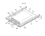
FIGS. 1 and2E , in the second joining step (S50), in order to complete the final exterior shape of the pouch type secondary battery, the additional joining step (S40) is followed by further sealing outer side portions of thefirst pouch sheet 120 and thesecond pouch sheet 130. That is to say, in the second joining step (S50), the final exterior shape of the pouch type secondary battery is completed using first and second mold jigs. Preferably, additionally sealedportions first side 121 of thefirst pouch sheet 120 and at thefirst side 131 of thesecond pouch sheet 130, respectively. Alternatively, the additionally sealedportions second side 122 of thefirst pouch sheet 120 and at thesecond side 132 of thesecond pouch sheet 130. In this embodiment, the widths W3 and W4 of sealed portions resulting from the second joining step (S50), positioned at thefirst sides second sides portion 140a, are formed over a relatively large area. For a better understanding of the present invention, however, only the newly sealed portions formed by the second joining step are defined as additionally sealedportions portions - Of course, the second joining step may also be performed on the
fourth sides second pouch sheets first sides second sides second pouch sheets fourth sides - Referring to
FIGS. 1 and2F , in the cutting (S60), outer side portions of thefirst pouch sheet 120 and thesecond pouch sheet 130 are cut for removal so as to be tailored to the use of the pouch type secondary battery. As such, the pouch type secondary battery can be made less bulky. In addition, in the folding (S70), side portions of thefirst pouch sheet 120 and thesecond pouch sheet 130 are folded to roughly face theelectrode assembly 110, so as to be tailored to the use of the pouch type secondary battery. -
FIGS. 3A and 3B illustrate a first joining step in a fabrication method for a pouch type secondary battery according to an embodiment of the present invention, andFIG. 3C is a partially enlarged view of a rectangular portion indicated by '3C' ofFIG. 3B . - As illustrated in
FIG. 3A , in the first joining step (S20), afirst jig 210 and asecond jig 220 are used. Thefirst jig 210 has a compressedportion 211 and thesecond jig 220 has a compressedportion 221, both of thecompressed portions first pouch sheet 120 and thesecond pouch sheet 130 are sealed to each other using the substantially planar,compressed portions first jig 210 and thesecond jig 220 being at high temperature. For example, thefirst sides second pouch sheets electrode assembly 110 accommodated inside between thefirst pouch sheet 120 and thesecond pouch sheet 130, are thermally fused using the substantially planar,compressed portions first jig 210 and thesecond jig 220 at high temperature. In addition, thesecond sides second pouch sheets electrode assembly 110, are thermally fused using another substantially planar, compressed portions 211' and 221' of first andsecond jig 210' and 220' at high temperature. - In such a manner, the first sealed
portion first pouch sheet 120 and thesecond pouch sheet 130. - In this embodiment, the substantially planar,
compressed portions first jig 210 and thesecond jig 220 may further include a plurality ofprotrusions first pouch sheet 120 and thesecond pouch sheet 130. Of course, the plurality ofprotrusions - As illustrated in
FIGS. 3B and 3C , the plurality ofprotrusions compressed portions first jig 210 and thesecond jig 220produce sealing marks portion 140a having the width W1. The sealing marks 125 and 135 are generally formed in theinsulation layer 120c and theinsulation layer 130c of the multi-layered first andsecond pouch sheets protrusions protrusions compressed portions first jig 210 and thesecond jig 220 one transferred to the first sealedportion 140a in forms of recesses. As a consequence the sealing marks 125 and 135 assume the same configuration as the protrusions. - Meanwhile, in the first joining step (S20), a space S is formed between the first sealed
portion 140a and theelectrode assembly 110. The space S may serve as a passage through which electrolyte flows smoothly in the injecting of the electrolyte (S30). In addition, the electrolyte is contained in the space S for a predetermined time of period, thereby allowing the electrolyte to be rapidly impregnated into theelectrode assembly 110. That is to say, the space S may function to improve the efficiency of impregnating the electrolyte into theelectrode assembly 110. - In the first joining step (S20), determination of the exterior shape of the pouch type secondary battery is still uncompleted. In practice, it is in the second joining step (S50) subsequent to the first joining step (S20), specifically through a forming process using molds, that the exterior shape of the pouch type secondary battery is completely determined.
- It will be appreciated that this process therefore results in an arrangement in which the pouch sheets closely conform to the shape of the electrode assembly because inner surfaces of the respective pouch sheets are in contact with an edge portion of the electrode assembly in a contact region that is adjacent the join between the pouch sheets. Although contact in these areas is particularly effective for meeting the objects of the invention, any contact between the pouch sheets and the electrode assembly as a consequence of the second joining step will tend to improve the conformity between the pouch sheets and the electrode assembly and hence provide a benefit.
-
FIGS. 4A and 4B illustrate a second joining step in a fabrication method of a pouch type secondary battery according to an embodiment of the present invention, andFIG. 4C is a partially enlarged view of a rectangular portion indicated by '4C' ofFIG. 4B . - As illustrated in
FIG. 4A , in the second joining step (S50), afirst mold jig 310 and asecond mold jig 320 are used. That is to say, after the additional joining step (S40), some outer side portions of thefirst pouch sheet 120 and thesecond pouch sheet 130 are additionally sealed using thefirst mold jig 310 and thesecond mold jig 320 of thefirst pouch sheet 120 and thesecond pouch sheet 130. Further, the final exterior shape of the pouch type secondary battery is determined through the second joining step (S50). In addition, as the result of the second joining step (S50), the space S (seeFIGS. 3A and 3B ) provided between theelectrode assembly 110 and the first sealedportion 140a (140b) is removed, thereby making the pouch type secondary battery more compact. That is to say, as illustrated inFIG. 4A , external surfaces of theelectrode assembly 110 are completely covered by thefirst pouch sheet 120 and thesecond pouch sheet 130. In other words, curved portions of thewound electrode assembly 110 are completely covered by thefirst pouch sheet 120 and thesecond pouch sheet 130, thereby achieving hermetically sealing without a gap. Accordingly, curved portions are also formed in thefirst pouch sheet 120 and thesecond pouch sheet 130 to correspond to the curved portions of thewound electrode assembly 110. - Although
FIG. 4A illustrates that thewound electrode assembly 110 having a cross section of a substantially elliptical shape, the invention can also be applied to a stack-type electrode assembly having a cross section of a substantially rectangular shape. That is to say, in case of using the stack-type electrode assembly having a cross section of a substantially rectangular shape, angled portions of theelectrode assembly 110 can be completely covered by thefirst pouch sheet 120 and thesecond pouch sheet 130, thereby achieving hermetically sealing without a gap. - As described above, the portions subjected to the additionally sealing are defined as the additionally sealed
portions portion 141 a is formed at thefirst sides first pouch sheet 120 and thesecond pouch sheet 130. In addition, the additionally sealedportion 141b is formed at thesecond sides first pouch sheet 120 and thesecond pouch sheet 130. Here, the second joining step may make widths W3 and W4 of the portions sealed to thefirst sides second sides first sides second sides portions 140a, are formed over a larger area than an area of the first sealedportions 140a. For a better understanding of the present invention, however, portions obtained by subtracting the portion with the width W1 and W2 from the portion with the width W3 and by subtracting the portion with the width W2 from the portion with the width W4 are defined as the additionally sealedportions - Meanwhile, the
first mold jig 310 and thesecond mold jig 320 include moldedportions 311 and 321, andcompressed portions portions 311 and 321 determining the exterior shapes of thefirst pouch sheet 120 and thesecond pouch sheet 130, and thecompressed portions portions portions 311 and 321 includecurves curves portions 311 and 321 compress thefirst pouch sheet 120 and thesecond pouch sheet 130, that is, inward portions of the additionally sealedportions compressed portions protrusions second pouch sheets - Accordingly, as illustrated in
FIGS. 4B and 4C , sealingmarks portions portion 141a by the plurality ofprotrusions compressed portions - Here, the second joining step creates a pitch difference between the sealing
marks portions 140a and between the sealingmarks portion 141a. That is to say, a pitch between the sealingmarks portions 140a is smaller than that between the sealingmarks portion 141 a. Reversely, the pitch between the sealingmarks portion 141a is larger than that between the sealingmarks portions 140a. Further, the number of the sealing marks 125 and 135 formed in the first sealedportions 140a is greater than that of the sealing marks 126 and 136 formed in the additionally sealedportion 141 a. This is because sealing has been performed twice on the first sealedportion 140a and once on the additionally sealedportion 141a. Of course, the sealing marks 126 and 136 are closer to the electrode assembly comparing to the sealing marks 125 and 135. In addition, the plurality of the sealing marks may take any of a wide variety of shapes, including lines, crosses, geometric shapes, grooves, protrusions, studs, grids and equivalents thereof, but not limited thereto. -
FIGS. 5A and 5B illustrate steps of cutting and folding in a fabrication method of a pouch type secondary battery according to an embodiment of the present invention. - As illustrated in
FIG. 5A , in the cutting (S60), unnecessary side portions of thefirst pouch sheet 120 and thesecond pouch sheet 130 are cut for removal. - As illustrated in
FIG. 5B , in the folding (S70), the side portions of thefirst pouch sheet 120 and thesecond pouch sheet 130 are folded to face theelectrode assembly 110. That is to say, the first sealedportions portions first pouch sheet 120 and thesecond pouch sheet 130 are folded approximately 90° either upward or downward. In some cases, the sealed portions in the left and the right sealed portions in the right may be folded in opposite directions. After the cutting (S60) and the folding (S70), the pouch type secondary battery can be miniaturized. -
FIG. 6 is a cross-sectional view schematically illustrating a transversely cut section of a pouch type secondary battery according to an embodiment of the present invention. - As illustrated in
FIG. 6 , the second sealedportion 140d formed at thefourth side 124 of thefirst pouch sheet 120 and at thefourth side 134 of thesecond pouch sheet 130 may also be folded either upward or downward. Here, since the second joining step has not been performed on the second sealedportion 140d, a space S for accommodating electrolyte is provided between theelectrode assembly 110 and the second sealedportion 140d. - Meanwhile, the
fourth side 124 of thefirst pouch sheet 120 and thefourth side 134 of thesecond pouch sheet 130 may be folded in the same direction as the first sealedportions portions portions 140a and140b and the additionally sealedportions -
FIGS. 7A through 7C illustrate steps in a fabrication method of a pouch type secondary battery according to an embodiment of the present invention. - As illustrated in
FIG. 7A , as the result of the additional joining step, the second sealedportion 140d is formed at thefourth sides second pouch sheets electrode assembly 110 and the second sealedportion 140d. The second sealedportion 140d may include a plurality of sealing marks formed using protrusions formed in jigs, which has already been described above. - As illustrated in
FIG. 7B , as the result of the second joining step, the additionally sealedportion 141 d is formed at thefourth sides second pouch sheets electrode assembly 110 and the second sealedportion 140d. That is to say, the first andsecond pouch sheets electrode assembly 110 without a gap. - In addition, as described above, the additionally sealed
portion 141d may include a plurality of sealing marks formed by the protrusions formed in the mold jigs. Of course, sealing marks may be additionally formed at the second sealedportion 140d as well. Eventually, the second sealedportion 140d may include a relatively large number of sealing marks. In addition, after performing the additionally sealing, unnecessary portions of the sealed portions may be cut for removal. - As illustrated in
FIG. 7C , the second sealedportion 140d and the additionally sealedportion 141d may be folded either upward or downward. Likewise, the second sealedportion 140d and the additionally sealedportion 141d may be folded in the same direction as the first sealedportions portions portions portions - As described above, although specific embodiments have been disclosed herein, they are to be interpreted in a descriptive sense only and not for purpose of limitation. Accordingly, it will be understood by those of ordinary skill in the art that various changes in form and details may be made without departing from the scope of the present invention as set forth in the following claims.
Claims (15)
- A fabrication process for a secondary battery, wherein the process comprises:locating an electrode assembly between a first pouch sheet and a second pouch sheet;performing a first joining step, in which respective portions of the first pouch sheet and the second pouch sheet are joined together, so as to form a seal that at least partially surrounds the electrode assembly;supplying the electrode assembly with an electrolyte; andperforming a second joining step, in which further respective portions of the first pouch sheet and the second pouch sheet are joined together in a region situated between the seal and the electrode assembly.
- A process according to Claim 1, wherein an opening is left between respective portions of the first pouch sheet and the second pouch sheet during the first joining step and the electrolyte is supplied to the electrode assembly via the said opening.
- A process according to Claim 2, wherein the electrode assembly comprises an electrode tab and the opening is left on a side of the electrode assembly that is substantially opposite to a side from where the electrode tab extends.
- A process according to Claim 2 or 3, comprising performing an additional joining step in which the opening is sealed after the electrolyte is supplied to the electrode assembly.
- A process according to any preceding claim, wherein the said respective portions of the first pouch sheet and the second pouch sheet that are joined together in the said first joining step are at least partially located in one or more edge regions of the first pouch sheet and the second pouch sheet.
- A process according to any preceding claim, further comprising folding at least a part of the said respective portions of the first pouch sheet and the second pouch sheet that have been joined during the said first joining step and arranging the folded part to lie alongside another part of either the first pouch sheet or the second pouch sheet.
- A process according to any preceding claim, wherein the first joining step comprises pressing together and thermally fusing the said respective portions of the first pouch sheet and second pouch sheet.
- A process according to Claim 7, wherein the said first joining step is executed using opposed first jigs that each have a plurality of protrusions that form corresponding first indentations on respective surfaces of the first pouch sheet and second pouch sheet.
- A process according to any preceding claim, wherein the second joining step substantially eliminates a void.
- A process according to any preceding claim, wherein the second joining step is executed using opposed second jigs that each have a compression surface substantially conforming to an outer surface profile of the electrode assembly.
- A process according to Claim 10, wherein the second jigs each have a plurality of protrusions that form corresponding second indentations on respective surfaces of the first pouch sheet and second pouch sheet.
- A secondary battery assembly, comprising:an electrode assembly;a first pouch sheet; anda second pouch sheet;wherein the first and second pouch sheets are joined together in a join region;characterised in that the join region is adjacent an edge surface of the electrode assembly and inner portions of the first and second pouch sheets are in contact with the edge surface of the electrode assembly.
- A secondary battery assembly according to Claim 12, wherein the join region comprises a first plurality of sealing marks arranged with a first pitch and a second plurality of sealing marks arranged with a second pitch.
- A secondary battery assembly according to Claim 13, wherein the second plurality of sealing marks is closer to the electrode assembly and the second pitch difference is larger than the first pitch difference.
- A secondary battery assembly according to Claim 13, wherein the sealing marks comprise grooves, protrusions, lines or crosses.
Applications Claiming Priority (2)
| Application Number | Priority Date | Filing Date | Title |
|---|---|---|---|
| US31913510P | 2010-03-30 | 2010-03-30 | |
| US13/020,759 US8771866B2 (en) | 2010-03-30 | 2011-02-03 | Pouch type secondary battery and the fabrication method thereof |
Publications (2)
| Publication Number | Publication Date |
|---|---|
| EP2375469A1 true EP2375469A1 (en) | 2011-10-12 |
| EP2375469B1 EP2375469B1 (en) | 2017-05-10 |
Family
ID=44202171
Family Applications (1)
| Application Number | Title | Priority Date | Filing Date |
|---|---|---|---|
| EP11250350.3A Active EP2375469B1 (en) | 2010-03-30 | 2011-03-21 | Secondary battery and a fabrication method thereof |
Country Status (5)
| Country | Link |
|---|---|
| US (1) | US8771866B2 (en) |
| EP (1) | EP2375469B1 (en) |
| JP (1) | JP5600078B2 (en) |
| KR (1) | KR101296949B1 (en) |
| CN (1) | CN102208673B (en) |
Cited By (2)
| Publication number | Priority date | Publication date | Assignee | Title |
|---|---|---|---|---|
| EP2816631A4 (en) * | 2012-02-13 | 2015-07-29 | Nissan Motor | Battery reinforcement method |
| EP3723152A4 (en) * | 2018-08-31 | 2021-03-24 | Lg Chem, Ltd. | Pouch, secondary battery including same, and method for manufacturing secondary battery |
Families Citing this family (30)
| Publication number | Priority date | Publication date | Assignee | Title |
|---|---|---|---|---|
| EP1508519A1 (en) * | 2003-08-20 | 2005-02-23 | Mars Incorporated | Method and device for packaging products and array of packaged products |
| EP1967465A1 (en) | 2007-03-05 | 2008-09-10 | Mars Incorporated | Packaged products and array or bandoleer of packaged products |
| JP5470404B2 (en) * | 2009-10-14 | 2014-04-16 | 株式会社日立製作所 | Battery control device and motor drive system |
| WO2013102269A1 (en) | 2012-01-05 | 2013-07-11 | Electrovaya Inc. | Thin film electrochemical cell with a polymer double seal |
| KR20130085719A (en) * | 2012-01-20 | 2013-07-30 | 에스케이이노베이션 주식회사 | Method and device of sealing a battery in a type of pouch |
| KR101863703B1 (en) | 2014-10-20 | 2018-06-01 | 주식회사 엘지화학 | Pouch-type secondary battery and method for manufacturing the same |
| JP2016126826A (en) * | 2014-12-26 | 2016-07-11 | 昭和電工パッケージング株式会社 | Method of manufacturing battery |
| KR101883536B1 (en) * | 2015-04-29 | 2018-07-30 | 주식회사 엘지화학 | Pouch type secondary battery and method of fabricating the same |
| KR102593580B1 (en) * | 2015-10-23 | 2023-10-23 | 삼성에스디아이 주식회사 | Rechargeable battery |
| KR101940150B1 (en) | 2015-12-11 | 2019-01-18 | 주식회사 엘지화학 | Sealing apparatus for secondary battery |
| KR102145492B1 (en) | 2016-06-14 | 2020-08-18 | 주식회사 엘지화학 | Battery System with Improved Rate Characteristic and Method for Generating Battery System |
| KR102566302B1 (en) | 2016-06-27 | 2023-08-11 | 삼성에스디아이 주식회사 | Secondary battery |
| KR102356496B1 (en) * | 2016-07-29 | 2022-01-28 | 삼성에스디아이 주식회사 | Rechargeable battery |
| CN109716574B (en) * | 2016-07-29 | 2022-01-18 | 三星Sdi株式会社 | Rechargeable battery |
| KR102112693B1 (en) * | 2016-08-09 | 2020-05-19 | 주식회사 엘지화학 | Secondary battery |
| KR102174607B1 (en) * | 2016-09-09 | 2020-11-05 | 주식회사 엘지화학 | Sealing Device for Battery Case Comprising Sealing Protrusion and Method of Manufacturing Battery Cell Using the Same |
| JP6284248B1 (en) * | 2016-11-22 | 2018-02-28 | セイコーインスツル株式会社 | Electrochemical cell and method for producing electrochemical cell |
| US11482747B2 (en) * | 2016-12-20 | 2022-10-25 | Sk Innovation Co., Ltd. | Pouch-type secondary battery |
| JP6610606B2 (en) * | 2017-04-21 | 2019-11-27 | トヨタ自動車株式会社 | Manufacturing method of laminated battery |
| EP3624209A4 (en) * | 2018-04-12 | 2021-01-06 | Ningde Amperex Technology Limited | Battery |
| JP7171351B2 (en) * | 2018-09-28 | 2022-11-15 | 積水化学工業株式会社 | LAMINATED SECONDARY BATTERY AND MANUFACTURING METHOD THEREOF |
| KR102216770B1 (en) * | 2019-10-11 | 2021-02-17 | 주식회사 클레버 | Apparatus for forming sealing portion of secondary battery pouch |
| DE102020111274A1 (en) * | 2020-04-24 | 2021-10-28 | Volkswagen Aktiengesellschaft | Method and device for the production of metal composite foils for battery cells |
| KR20220048453A (en) | 2020-10-12 | 2022-04-19 | 주식회사 엘지에너지솔루션 | The Apparatus For Sealing Battery Case and Secondary battery manufactured using same |
| JP2023542175A (en) | 2020-10-12 | 2023-10-05 | エルジー エナジー ソリューション リミテッド | Battery case sealing device and secondary battery manufactured using the same |
| CN113131100B (en) * | 2021-03-31 | 2023-06-23 | 宁德新能源科技有限公司 | Battery cell, battery and electric equipment |
| CN115347286B (en) * | 2021-05-14 | 2024-02-27 | 中创新航科技股份有限公司 | Battery manufacturing method and battery |
| CN115347282A (en) * | 2021-05-14 | 2022-11-15 | 中创新航科技股份有限公司 | Battery, battery pack, and battery manufacturing method |
| KR20220161969A (en) * | 2021-05-31 | 2022-12-07 | 현대자동차주식회사 | Pouch type lithium secondary battery sealer, sealing method and pouch type lithium secondary battery manufactured by the same |
| KR20230055033A (en) * | 2021-10-18 | 2023-04-25 | 주식회사 엘지에너지솔루션 | Battery Cell Comprising Sealing Part Having Embossed Pattern formed Therein and Sealing Block for Manufacturing the Same |
Citations (3)
| Publication number | Priority date | Publication date | Assignee | Title |
|---|---|---|---|---|
| US6371996B1 (en) * | 1999-04-26 | 2002-04-16 | Toshiba Battery Co., Ltd. | Manufacturing method of batteries |
| US20020164441A1 (en) * | 2001-03-01 | 2002-11-07 | The University Of Chicago | Packaging for primary and secondary batteries |
| WO2007061262A1 (en) * | 2005-11-28 | 2007-05-31 | Lg Chem, Ltd. | Small battery pack employing pcm on side sealing part |
Family Cites Families (22)
| Publication number | Priority date | Publication date | Assignee | Title |
|---|---|---|---|---|
| JPS6129065A (en) | 1984-07-19 | 1986-02-08 | Matsushita Electric Ind Co Ltd | Flat type nonaqueous electrolyte cell |
| JPS61179059A (en) | 1985-02-01 | 1986-08-11 | Matsushita Electric Ind Co Ltd | Manufacture of flat cell |
| JP2899361B2 (en) * | 1990-05-24 | 1999-06-02 | 東芝電池株式会社 | Manufacturing method of flat battery |
| JP4019229B2 (en) | 1997-03-21 | 2007-12-12 | 株式会社ジーエス・ユアサコーポレーション | Battery manufacturing method |
| WO1999060652A1 (en) * | 1998-05-20 | 1999-11-25 | Osaka Gas Company Limited | Nonaqueous secondary cell and method for controlling the same |
| US6207318B1 (en) * | 1998-06-22 | 2001-03-27 | Eagle-Picher Energy Products Corporation | Electrochemical batteries with restricted liquid electrolyte volume |
| JP2000149993A (en) | 1998-11-16 | 2000-05-30 | Furukawa Electric Co Ltd:The | Film-like lithium secondary battery |
| JP2000173564A (en) | 1998-12-03 | 2000-06-23 | Tokai Rubber Ind Ltd | Thin battery bag body |
| JP4668370B2 (en) | 1999-04-08 | 2011-04-13 | 大日本印刷株式会社 | Polymer battery |
| US6379838B1 (en) * | 1999-04-14 | 2002-04-30 | Alcatel | Cell package |
| JP3460805B2 (en) | 1999-06-24 | 2003-10-27 | 日本電気株式会社 | Battery manufacturing method |
| JP4171855B2 (en) | 1999-08-06 | 2008-10-29 | 株式会社ジーエス・ユアサコーポレーション | battery |
| JP2001084972A (en) | 1999-09-13 | 2001-03-30 | Toshiba Battery Co Ltd | Manufacturing method thin battery |
| WO2001056093A1 (en) | 2000-01-24 | 2001-08-02 | Mitsubishi Denki Kabushiki Kaisha | Package for material containing nonaqueous solvent and cell comprising the same |
| JP2001243931A (en) | 2000-02-28 | 2001-09-07 | Kyocera Corp | Lithium battery |
| JP2001325992A (en) | 2000-05-15 | 2001-11-22 | Awa Eng Co | Manufacturing method of cell which uses laminate sheet as packaging case |
| JP2004095383A (en) * | 2002-08-30 | 2004-03-25 | Toshiba Corp | Nonaqueous electrolyte secondary battery |
| KR20040079531A (en) | 2003-03-07 | 2004-09-16 | 에프원 주식회사 | Vacuum-absorption type positioning forming mold for aluminum pouch |
| JP4559406B2 (en) * | 2005-12-29 | 2010-10-06 | 三星エスディアイ株式会社 | Pouch-type battery |
| KR100778982B1 (en) | 2005-12-29 | 2007-11-22 | 삼성에스디아이 주식회사 | Pouch case and pouch type secondary battery employing the same |
| KR101108447B1 (en) | 2006-08-28 | 2012-02-08 | 주식회사 엘지화학 | Process for Preparation of Pouch-typed Secondary Battery Having Excellent Sealing Property |
| JP5226332B2 (en) | 2007-02-21 | 2013-07-03 | リケンテクノス株式会社 | Lithium secondary battery using laminate exterior material |
-
2011
- 2011-02-03 US US13/020,759 patent/US8771866B2/en active Active
- 2011-02-09 KR KR1020110011418A patent/KR101296949B1/en active IP Right Grant
- 2011-02-15 JP JP2011029717A patent/JP5600078B2/en active Active
- 2011-03-21 EP EP11250350.3A patent/EP2375469B1/en active Active
- 2011-03-23 CN CN201110070106.5A patent/CN102208673B/en active Active
Patent Citations (3)
| Publication number | Priority date | Publication date | Assignee | Title |
|---|---|---|---|---|
| US6371996B1 (en) * | 1999-04-26 | 2002-04-16 | Toshiba Battery Co., Ltd. | Manufacturing method of batteries |
| US20020164441A1 (en) * | 2001-03-01 | 2002-11-07 | The University Of Chicago | Packaging for primary and secondary batteries |
| WO2007061262A1 (en) * | 2005-11-28 | 2007-05-31 | Lg Chem, Ltd. | Small battery pack employing pcm on side sealing part |
Cited By (4)
| Publication number | Priority date | Publication date | Assignee | Title |
|---|---|---|---|---|
| EP2816631A4 (en) * | 2012-02-13 | 2015-07-29 | Nissan Motor | Battery reinforcement method |
| US9553285B2 (en) | 2012-02-13 | 2017-01-24 | Nissan Motor Co., Ltd. | Battery reinforcement method |
| EP3723152A4 (en) * | 2018-08-31 | 2021-03-24 | Lg Chem, Ltd. | Pouch, secondary battery including same, and method for manufacturing secondary battery |
| US11791517B2 (en) | 2018-08-31 | 2023-10-17 | Lg Energy Solution, Ltd. | Pouch, secondary battery comprising the same, and method for manufacturing the secondary battery |
Also Published As
| Publication number | Publication date |
|---|---|
| JP5600078B2 (en) | 2014-10-01 |
| CN102208673B (en) | 2014-11-05 |
| EP2375469B1 (en) | 2017-05-10 |
| KR20110109824A (en) | 2011-10-06 |
| US8771866B2 (en) | 2014-07-08 |
| KR101296949B1 (en) | 2013-08-14 |
| JP2011210707A (en) | 2011-10-20 |
| US20110244315A1 (en) | 2011-10-06 |
| CN102208673A (en) | 2011-10-05 |
Similar Documents
| Publication | Publication Date | Title |
|---|---|---|
| EP2375469B1 (en) | Secondary battery and a fabrication method thereof | |
| EP2535961B1 (en) | Pouch type secondary battery and method for manufacturing the same | |
| US11316235B2 (en) | Prismatic secondary battery, assembled battery using the same and method of producing the same | |
| EP3070760B1 (en) | Prismatic battery | |
| KR100624967B1 (en) | Pouch type lithium secondary battery and the method of fabricating the same | |
| KR101135498B1 (en) | Rechargeable battery and can of the same | |
| JP6860091B2 (en) | Power storage module and manufacturing method of power storage module | |
| US20110311863A1 (en) | Secondary battery | |
| US9318770B2 (en) | Battery and method of manufacturing battery | |
| US20230231282A1 (en) | Secondary battery | |
| EP3331082B1 (en) | Method for manufacturing secondary battery and method for manufacturing electrode assembly | |
| EP4250467A1 (en) | Secondary battery and manufacturing method therefor | |
| JP5514618B2 (en) | Secondary battery | |
| US20220384924A1 (en) | Secondary Battery and Method for Manufacturing Same | |
| JP2021044079A (en) | Power storage module, and manufacturing method of power storage module | |
| US20230083775A1 (en) | Battery cell having protective member | |
| KR100591443B1 (en) | Pouch-type lithium secondary battery and manufacturing method thereof | |
| JP7247893B2 (en) | Storage element | |
| US20230207933A1 (en) | Secondary Battery and Method for Manufacturing the Same, and Battery Pack | |
| KR102350769B1 (en) | Secondary battery | |
| KR20230101249A (en) | Secondary battery | |
| KR100591439B1 (en) | Manufacturing method of pouch type lithium secondary battery | |
| KR20230157871A (en) | Electrode assembly, manufacturing method thereof and battery cell including same | |
| KR20220091378A (en) | Pouch for secondary battery, method of manufacturing thereof and manufacturing method of secondary battery | |
| CN113875043A (en) | Secondary battery |
Legal Events
| Date | Code | Title | Description |
|---|---|---|---|
| PUAI | Public reference made under article 153(3) epc to a published international application that has entered the european phase |
Free format text: ORIGINAL CODE: 0009012 |
|
| AK | Designated contracting states |
Kind code of ref document: A1 Designated state(s): AL AT BE BG CH CY CZ DE DK EE ES FI FR GB GR HR HU IE IS IT LI LT LU LV MC MK MT NL NO PL PT RO RS SE SI SK SM TR |
|
| AX | Request for extension of the european patent |
Extension state: BA ME |
|
| 17P | Request for examination filed |
Effective date: 20120110 |
|
| 17Q | First examination report despatched |
Effective date: 20121017 |
|
| GRAP | Despatch of communication of intention to grant a patent |
Free format text: ORIGINAL CODE: EPIDOSNIGR1 |
|
| INTG | Intention to grant announced |
Effective date: 20161122 |
|
| GRAS | Grant fee paid |
Free format text: ORIGINAL CODE: EPIDOSNIGR3 |
|
| GRAA | (expected) grant |
Free format text: ORIGINAL CODE: 0009210 |
|
| AK | Designated contracting states |
Kind code of ref document: B1 Designated state(s): AL AT BE BG CH CY CZ DE DK EE ES FI FR GB GR HR HU IE IS IT LI LT LU LV MC MK MT NL NO PL PT RO RS SE SI SK SM TR |
|
| REG | Reference to a national code |
Ref country code: GB Ref legal event code: FG4D |
|
| REG | Reference to a national code |
Ref country code: AT Ref legal event code: REF Ref document number: 893168 Country of ref document: AT Kind code of ref document: T Effective date: 20170515 Ref country code: CH Ref legal event code: EP |
|
| REG | Reference to a national code |
Ref country code: IE Ref legal event code: FG4D |
|
| REG | Reference to a national code |
Ref country code: DE Ref legal event code: R096 Ref document number: 602011037761 Country of ref document: DE |
|
| REG | Reference to a national code |
Ref country code: NL Ref legal event code: MP Effective date: 20170510 |
|
| REG | Reference to a national code |
Ref country code: LT Ref legal event code: MG4D |
|
| REG | Reference to a national code |
Ref country code: AT Ref legal event code: MK05 Ref document number: 893168 Country of ref document: AT Kind code of ref document: T Effective date: 20170510 |
|
| PG25 | Lapsed in a contracting state [announced via postgrant information from national office to epo] |
Ref country code: HR Free format text: LAPSE BECAUSE OF FAILURE TO SUBMIT A TRANSLATION OF THE DESCRIPTION OR TO PAY THE FEE WITHIN THE PRESCRIBED TIME-LIMIT Effective date: 20170510 Ref country code: AT Free format text: LAPSE BECAUSE OF FAILURE TO SUBMIT A TRANSLATION OF THE DESCRIPTION OR TO PAY THE FEE WITHIN THE PRESCRIBED TIME-LIMIT Effective date: 20170510 Ref country code: FI Free format text: LAPSE BECAUSE OF FAILURE TO SUBMIT A TRANSLATION OF THE DESCRIPTION OR TO PAY THE FEE WITHIN THE PRESCRIBED TIME-LIMIT Effective date: 20170510 Ref country code: LT Free format text: LAPSE BECAUSE OF FAILURE TO SUBMIT A TRANSLATION OF THE DESCRIPTION OR TO PAY THE FEE WITHIN THE PRESCRIBED TIME-LIMIT Effective date: 20170510 Ref country code: GR Free format text: LAPSE BECAUSE OF FAILURE TO SUBMIT A TRANSLATION OF THE DESCRIPTION OR TO PAY THE FEE WITHIN THE PRESCRIBED TIME-LIMIT Effective date: 20170811 Ref country code: ES Free format text: LAPSE BECAUSE OF FAILURE TO SUBMIT A TRANSLATION OF THE DESCRIPTION OR TO PAY THE FEE WITHIN THE PRESCRIBED TIME-LIMIT Effective date: 20170510 Ref country code: NO Free format text: LAPSE BECAUSE OF FAILURE TO SUBMIT A TRANSLATION OF THE DESCRIPTION OR TO PAY THE FEE WITHIN THE PRESCRIBED TIME-LIMIT Effective date: 20170810 |
|
| PG25 | Lapsed in a contracting state [announced via postgrant information from national office to epo] |
Ref country code: SE Free format text: LAPSE BECAUSE OF FAILURE TO SUBMIT A TRANSLATION OF THE DESCRIPTION OR TO PAY THE FEE WITHIN THE PRESCRIBED TIME-LIMIT Effective date: 20170510 Ref country code: IS Free format text: LAPSE BECAUSE OF FAILURE TO SUBMIT A TRANSLATION OF THE DESCRIPTION OR TO PAY THE FEE WITHIN THE PRESCRIBED TIME-LIMIT Effective date: 20170910 Ref country code: RS Free format text: LAPSE BECAUSE OF FAILURE TO SUBMIT A TRANSLATION OF THE DESCRIPTION OR TO PAY THE FEE WITHIN THE PRESCRIBED TIME-LIMIT Effective date: 20170510 Ref country code: NL Free format text: LAPSE BECAUSE OF FAILURE TO SUBMIT A TRANSLATION OF THE DESCRIPTION OR TO PAY THE FEE WITHIN THE PRESCRIBED TIME-LIMIT Effective date: 20170510 Ref country code: PL Free format text: LAPSE BECAUSE OF FAILURE TO SUBMIT A TRANSLATION OF THE DESCRIPTION OR TO PAY THE FEE WITHIN THE PRESCRIBED TIME-LIMIT Effective date: 20170510 Ref country code: LV Free format text: LAPSE BECAUSE OF FAILURE TO SUBMIT A TRANSLATION OF THE DESCRIPTION OR TO PAY THE FEE WITHIN THE PRESCRIBED TIME-LIMIT Effective date: 20170510 Ref country code: BG Free format text: LAPSE BECAUSE OF FAILURE TO SUBMIT A TRANSLATION OF THE DESCRIPTION OR TO PAY THE FEE WITHIN THE PRESCRIBED TIME-LIMIT Effective date: 20170810 |
|
| PG25 | Lapsed in a contracting state [announced via postgrant information from national office to epo] |
Ref country code: EE Free format text: LAPSE BECAUSE OF FAILURE TO SUBMIT A TRANSLATION OF THE DESCRIPTION OR TO PAY THE FEE WITHIN THE PRESCRIBED TIME-LIMIT Effective date: 20170510 Ref country code: CZ Free format text: LAPSE BECAUSE OF FAILURE TO SUBMIT A TRANSLATION OF THE DESCRIPTION OR TO PAY THE FEE WITHIN THE PRESCRIBED TIME-LIMIT Effective date: 20170510 Ref country code: SK Free format text: LAPSE BECAUSE OF FAILURE TO SUBMIT A TRANSLATION OF THE DESCRIPTION OR TO PAY THE FEE WITHIN THE PRESCRIBED TIME-LIMIT Effective date: 20170510 Ref country code: RO Free format text: LAPSE BECAUSE OF FAILURE TO SUBMIT A TRANSLATION OF THE DESCRIPTION OR TO PAY THE FEE WITHIN THE PRESCRIBED TIME-LIMIT Effective date: 20170510 Ref country code: DK Free format text: LAPSE BECAUSE OF FAILURE TO SUBMIT A TRANSLATION OF THE DESCRIPTION OR TO PAY THE FEE WITHIN THE PRESCRIBED TIME-LIMIT Effective date: 20170510 |
|
| REG | Reference to a national code |
Ref country code: DE Ref legal event code: R097 Ref document number: 602011037761 Country of ref document: DE |
|
| REG | Reference to a national code |
Ref country code: FR Ref legal event code: PLFP Year of fee payment: 8 |
|
| PG25 | Lapsed in a contracting state [announced via postgrant information from national office to epo] |
Ref country code: IT Free format text: LAPSE BECAUSE OF FAILURE TO SUBMIT A TRANSLATION OF THE DESCRIPTION OR TO PAY THE FEE WITHIN THE PRESCRIBED TIME-LIMIT Effective date: 20170510 Ref country code: SM Free format text: LAPSE BECAUSE OF FAILURE TO SUBMIT A TRANSLATION OF THE DESCRIPTION OR TO PAY THE FEE WITHIN THE PRESCRIBED TIME-LIMIT Effective date: 20170510 |
|
| PLBE | No opposition filed within time limit |
Free format text: ORIGINAL CODE: 0009261 |
|
| STAA | Information on the status of an ep patent application or granted ep patent |
Free format text: STATUS: NO OPPOSITION FILED WITHIN TIME LIMIT |
|
| 26N | No opposition filed |
Effective date: 20180213 |
|
| PG25 | Lapsed in a contracting state [announced via postgrant information from national office to epo] |
Ref country code: SI Free format text: LAPSE BECAUSE OF FAILURE TO SUBMIT A TRANSLATION OF THE DESCRIPTION OR TO PAY THE FEE WITHIN THE PRESCRIBED TIME-LIMIT Effective date: 20170510 |
|
| REG | Reference to a national code |
Ref country code: CH Ref legal event code: PL |
|
| PG25 | Lapsed in a contracting state [announced via postgrant information from national office to epo] |
Ref country code: MC Free format text: LAPSE BECAUSE OF FAILURE TO SUBMIT A TRANSLATION OF THE DESCRIPTION OR TO PAY THE FEE WITHIN THE PRESCRIBED TIME-LIMIT Effective date: 20170510 |
|
| REG | Reference to a national code |
Ref country code: BE Ref legal event code: MM Effective date: 20180331 |
|
| REG | Reference to a national code |
Ref country code: IE Ref legal event code: MM4A |
|
| PG25 | Lapsed in a contracting state [announced via postgrant information from national office to epo] |
Ref country code: LU Free format text: LAPSE BECAUSE OF NON-PAYMENT OF DUE FEES Effective date: 20180321 |
|
| PG25 | Lapsed in a contracting state [announced via postgrant information from national office to epo] |
Ref country code: IE Free format text: LAPSE BECAUSE OF NON-PAYMENT OF DUE FEES Effective date: 20180321 |
|
| PG25 | Lapsed in a contracting state [announced via postgrant information from national office to epo] |
Ref country code: CH Free format text: LAPSE BECAUSE OF NON-PAYMENT OF DUE FEES Effective date: 20180331 Ref country code: LI Free format text: LAPSE BECAUSE OF NON-PAYMENT OF DUE FEES Effective date: 20180331 Ref country code: BE Free format text: LAPSE BECAUSE OF NON-PAYMENT OF DUE FEES Effective date: 20180331 |
|
| PG25 | Lapsed in a contracting state [announced via postgrant information from national office to epo] |
Ref country code: MT Free format text: LAPSE BECAUSE OF NON-PAYMENT OF DUE FEES Effective date: 20180321 |
|
| PG25 | Lapsed in a contracting state [announced via postgrant information from national office to epo] |
Ref country code: TR Free format text: LAPSE BECAUSE OF FAILURE TO SUBMIT A TRANSLATION OF THE DESCRIPTION OR TO PAY THE FEE WITHIN THE PRESCRIBED TIME-LIMIT Effective date: 20170510 |
|
| PG25 | Lapsed in a contracting state [announced via postgrant information from national office to epo] |
Ref country code: HU Free format text: LAPSE BECAUSE OF FAILURE TO SUBMIT A TRANSLATION OF THE DESCRIPTION OR TO PAY THE FEE WITHIN THE PRESCRIBED TIME-LIMIT; INVALID AB INITIO Effective date: 20110321 Ref country code: PT Free format text: LAPSE BECAUSE OF FAILURE TO SUBMIT A TRANSLATION OF THE DESCRIPTION OR TO PAY THE FEE WITHIN THE PRESCRIBED TIME-LIMIT Effective date: 20170510 |
|
| PG25 | Lapsed in a contracting state [announced via postgrant information from national office to epo] |
Ref country code: CY Free format text: LAPSE BECAUSE OF FAILURE TO SUBMIT A TRANSLATION OF THE DESCRIPTION OR TO PAY THE FEE WITHIN THE PRESCRIBED TIME-LIMIT Effective date: 20170510 Ref country code: MK Free format text: LAPSE BECAUSE OF NON-PAYMENT OF DUE FEES Effective date: 20170510 |
|
| PG25 | Lapsed in a contracting state [announced via postgrant information from national office to epo] |
Ref country code: AL Free format text: LAPSE BECAUSE OF FAILURE TO SUBMIT A TRANSLATION OF THE DESCRIPTION OR TO PAY THE FEE WITHIN THE PRESCRIBED TIME-LIMIT Effective date: 20170510 |
|
| REG | Reference to a national code |
Ref country code: DE Ref legal event code: R079 Ref document number: 602011037761 Country of ref document: DE Free format text: PREVIOUS MAIN CLASS: H01M0002020000 Ipc: H01M0050100000 |
|
| PGFP | Annual fee paid to national office [announced via postgrant information from national office to epo] |
Ref country code: FR Payment date: 20230309 Year of fee payment: 13 |
|
| PGFP | Annual fee paid to national office [announced via postgrant information from national office to epo] |
Ref country code: GB Payment date: 20230223 Year of fee payment: 13 Ref country code: DE Payment date: 20230228 Year of fee payment: 13 |
|
| P01 | Opt-out of the competence of the unified patent court (upc) registered |
Effective date: 20230528 |