EP2375668A2 - Multi-dimensional signal of reduced Peak-to-RMS ratio - Google Patents
Multi-dimensional signal of reduced Peak-to-RMS ratio Download PDFInfo
- Publication number
- EP2375668A2 EP2375668A2 EP11152874A EP11152874A EP2375668A2 EP 2375668 A2 EP2375668 A2 EP 2375668A2 EP 11152874 A EP11152874 A EP 11152874A EP 11152874 A EP11152874 A EP 11152874A EP 2375668 A2 EP2375668 A2 EP 2375668A2
- Authority
- EP
- European Patent Office
- Prior art keywords
- constellation
- diamond
- radio signal
- points
- peak
- Prior art date
- Legal status (The legal status is an assumption and is not a legal conclusion. Google has not performed a legal analysis and makes no representation as to the accuracy of the status listed.)
- Granted
Links
- 238000000034 method Methods 0.000 claims abstract description 46
- 238000001228 spectrum Methods 0.000 claims description 20
- 239000002131 composite material Substances 0.000 claims description 14
- 230000000994 depressogenic effect Effects 0.000 claims description 5
- 239000010432 diamond Substances 0.000 description 49
- 229910003460 diamond Inorganic materials 0.000 description 46
- 239000011159 matrix material Substances 0.000 description 24
- 230000000875 corresponding effect Effects 0.000 description 23
- 238000010586 diagram Methods 0.000 description 15
- 230000009467 reduction Effects 0.000 description 8
- 230000005540 biological transmission Effects 0.000 description 6
- 238000001914 filtration Methods 0.000 description 6
- 230000001413 cellular effect Effects 0.000 description 5
- 230000002596 correlated effect Effects 0.000 description 4
- 230000006872 improvement Effects 0.000 description 4
- 230000010287 polarization Effects 0.000 description 4
- 230000007480 spreading Effects 0.000 description 4
- 238000007476 Maximum Likelihood Methods 0.000 description 3
- 230000006735 deficit Effects 0.000 description 3
- 230000006870 function Effects 0.000 description 3
- 238000012986 modification Methods 0.000 description 3
- 230000004048 modification Effects 0.000 description 3
- 230000003595 spectral effect Effects 0.000 description 3
- 101100063432 Caenorhabditis elegans dim-1 gene Proteins 0.000 description 2
- 108010003272 Hyaluronate lyase Proteins 0.000 description 2
- 230000000881 depressing effect Effects 0.000 description 2
- 230000000694 effects Effects 0.000 description 2
- 230000010363 phase shift Effects 0.000 description 2
- 230000008569 process Effects 0.000 description 2
- 238000006467 substitution reaction Methods 0.000 description 2
- 238000012360 testing method Methods 0.000 description 2
- 238000012935 Averaging Methods 0.000 description 1
- 239000000654 additive Substances 0.000 description 1
- 230000000996 additive effect Effects 0.000 description 1
- 238000013459 approach Methods 0.000 description 1
- 238000004364 calculation method Methods 0.000 description 1
- 230000008859 change Effects 0.000 description 1
- 230000003111 delayed effect Effects 0.000 description 1
- 230000001419 dependent effect Effects 0.000 description 1
- 238000001514 detection method Methods 0.000 description 1
- 238000003384 imaging method Methods 0.000 description 1
- 230000036039 immunity Effects 0.000 description 1
- 238000012545 processing Methods 0.000 description 1
- 230000008707 rearrangement Effects 0.000 description 1
- 230000004044 response Effects 0.000 description 1
- 230000007704 transition Effects 0.000 description 1
Images


Classifications
-
- H—ELECTRICITY
- H04—ELECTRIC COMMUNICATION TECHNIQUE
- H04L—TRANSMISSION OF DIGITAL INFORMATION, e.g. TELEGRAPHIC COMMUNICATION
- H04L27/00—Modulated-carrier systems
- H04L27/32—Carrier systems characterised by combinations of two or more of the types covered by groups H04L27/02, H04L27/10, H04L27/18 or H04L27/26
- H04L27/34—Amplitude- and phase-modulated carrier systems, e.g. quadrature-amplitude modulated carrier systems
- H04L27/3405—Modifications of the signal space to increase the efficiency of transmission, e.g. reduction of the bit error rate, bandwidth, or average power
- H04L27/3411—Modifications of the signal space to increase the efficiency of transmission, e.g. reduction of the bit error rate, bandwidth, or average power reducing the peak to average power ratio or the mean power of the constellation; Arrangements for increasing the shape gain of a signal set
-
- H—ELECTRICITY
- H04—ELECTRIC COMMUNICATION TECHNIQUE
- H04L—TRANSMISSION OF DIGITAL INFORMATION, e.g. TELEGRAPHIC COMMUNICATION
- H04L27/00—Modulated-carrier systems
- H04L27/32—Carrier systems characterised by combinations of two or more of the types covered by groups H04L27/02, H04L27/10, H04L27/18 or H04L27/26
- H04L27/34—Amplitude- and phase-modulated carrier systems, e.g. quadrature-amplitude modulated carrier systems
- H04L27/3405—Modifications of the signal space to increase the efficiency of transmission, e.g. reduction of the bit error rate, bandwidth, or average power
- H04L27/3416—Modifications of the signal space to increase the efficiency of transmission, e.g. reduction of the bit error rate, bandwidth, or average power in which the information is carried by both the individual signal points and the subset to which the individual points belong, e.g. using coset coding, lattice coding, or related schemes
-
- H—ELECTRICITY
- H04—ELECTRIC COMMUNICATION TECHNIQUE
- H04B—TRANSMISSION
- H04B2201/00—Indexing scheme relating to details of transmission systems not covered by a single group of H04B3/00 - H04B13/00
- H04B2201/69—Orthogonal indexing scheme relating to spread spectrum techniques in general
- H04B2201/707—Orthogonal indexing scheme relating to spread spectrum techniques in general relating to direct sequence modulation
- H04B2201/70706—Orthogonal indexing scheme relating to spread spectrum techniques in general relating to direct sequence modulation with means for reducing the peak-to-average power ratio
Definitions
- the present invention relates in general to the wireless telecommunications field and, in particular, to a transmitter and a method for generating a radio signal with a reduced ratio of peak amplitude to root-mean-square amplitude which helps to improve the transmit efficiency of the transmitter's power amplifier.
- the present invention relates to a receiver that can decode the radio signal.
- a communications signal such as a radio signal can be thought of as having an instantaneous complex value on a two-dimensional complex plane, where the coordinate in one dimension is the signed amplitude of a sinusoidal component of the radio signal and the coordinate in the second dimension is the signed amplitude of a cosinusoidal component of the radio signal. Since the cosine function and the sine function are mutually orthogonal functions, their correlation is zero, which means that the two dimensions are at right angles with respect to each other. The two dimensions are commonly labeled I and Q for "In-phase" and "Quadrature". No other orthogonal dimensions exist in this signal space, which is a plane.
- symbols representing groups of bits can be located on the I, Q plane such that any two symbols are sufficiently separated from one another to avoid confusion, so long as the signal-to-noise ratio is high enough.
- 16 symbols can be located on a 4x4 grid known as 16QAM, and four binary bits assigned to each point.
- 64QAM 64 symbols can be located on a BX8 grid and 6 binary bits assigned to each point.
- Non-rectangular constellations of points can also be used, for example 16-PSK (phase shift keying) in which 16 points are equispaced in angle around a circle, and 4 binary bits are allocated to each of the points.
- US Patent No. 4,597,090 filed April 14, 1983 , discloses a modulation scheme for a single physical channel in which the two dimensions in signal space (I,Q) on m sequential signal samples are considered to form a 2m dimensional space, and where mN data bits are encoded into the 2m dimensions in such a way as to obtain a coding gain by constraining the selection of I,Q value of one signal sample to depend on the selection of I,Q values for the other signal samples.
- This is a form of Trellis Coding, and is related to obtaining a coding gain but is silent about obtaining a reduction of the peak-to-rms ratio of the radio signal which is a subject that is related to the present discussion.
- the 3rd Generation cellular system known as WCDMA or UMTS currently has a method under specification known as HSPA which enables the transmission of higher data rates from a mobile phone to a network (or base station).
- HSPA uses an approach called "Multi-code CDMA".
- Multi-code CDMA In this Multi-code CDMA system, each data symbol is spread out in time and spectrum by combining it with a spreading code.
- the codes used to transmit signals from the base station are coordinated at the base station so that they are mutually orthogonal.
- the uplink mobile phone to base station
- the coordination needed between different mobile phones to achieve orthogonality is considered too difficult to implement, so each mobile phone uses a different random code sequence.
- each mobile phone it is still possible to generate several random code sequences that are coordinated among themselves to be mutually orthogonal.
- Each of these orthogonal codes may then carry a symbol sub-stream so that the combined symbol stream rate is enhanced.
- the mobile phone's available transmitter power is going to be divided between the different codes which means that the range over which each sub-stream may be successfully received and decoded error free is going to be reduced.
- the reduction of power per each sub-stream in a multi-code modulation signal transmitted, from a mobile phone is worse than would be expected by merely dividing the transmitter power by the total number of sub-streams. This is because it is not so much the average power that is constrained by battery voltage, but rather the peak signal amplitude, which happens to be limited by the battery voltage.
- the present invention provides a method for reducing a peak-to-rms ratio in a transmitted radio signal while placing a limit on the peak composite symbol amplitude when utilizing multi-dimensional modulation.
- the method includes the steps of: (a) encoding information into a stream of binary bits; (b) forming a plurality of groups of bits from the stream of binary bits, wherein the plurality of groups of bits represent a plurality of data symbols; (c) representing each data symbol by a set of coordinates in a multidimensional space, wherein a number of dimensions in the multidimensional space correspond to a number of at least three orthogonal components which eventually comprise the transmitted radio signal; and (d) choosing coordinates for each data symbol such that each data symbol is located at a minimum distance away from a nearest other data symbol in the multidimensional space and also such that the peak composite symbol amplitude to root-mean-square amplitude of the transmitted radio signals is minimized.
- the present invention provides a method of communicating data symbols resulting in a transmitted signal with a reduced ratio of peak amplitude to root-mean-square amplitude.
- the method includes the steps of:
- the present invention provides a transmitter that reduces a peak-to-rms ratio in a radio signal while placing a limit on the peak composite symbol amplitude when utilizing multi-dimensional modulation.
- the transmitter includes: (a) an encoder that divides groups of data bits into a first subgroup and a second subgroup; (b) the encoder uses the first subgroup of bits to select one of a number of constellation points that are distributed within a first multi-dimensional space, where a location of the constellation points have been determined such that a sum of their coordinates is less than a desired maximum value, where the coordinates of the selected constellation point are used to set values of real parts of corresponding complex numbers; (c) the encoder uses the second subgroup of bits to select another one of a number of constellation points that are distributed within a second multidimensional space, where a location of the constellation points have been determined such that a sum of their coordinates is less than a desired maximum value, where the coordinates of the selected constellation point are then used to set values of imaginary parts of corresponding
- the present invention provides a receiver that decodes a radio signal which has a reduced peak-to-rms ratio and a limited peak composite symbol amplitude.
- the receiver includes a decoder with a processor that implements processor-executable instructions from a memory to decode the radio signal by: (a) determining a facet of a diamond-shaped constellation on or within which a data symbol of the radio signal lies; (b) determining a subset of points on the facet within which the data symbol of the radio signal lies; (c) determining a point within the subset of points which is closest to coordinate values of the data symbol; and (d) determining the data symbol from the combination of the facet, the subset of points, and the closest point.
- the present invention provides a receiver that decodes a radio signal which has a reduced peak-to-rms ratio and a limited peak composite symbol amplitude.
- the receiver includes a decoder with a processor that implements processor-executable instructions from a memory to decode the radio signal by: (a) hypothesizing a first of multiple constellation points on a first diamond-shaped constellation where the first constellation point is associated with a data symbol of the radio signal; (b) determining, given the hypothesized first constellation point, a second constellation point on a second diamond-shaped constellation where the second constellation point is associated with a data symbol of the radio signal; (c) determining a metric describing how accurately the hypothesized first constellation point and the associated determined second constellation point predict the received radio signal; and (d) comparing the metric for all possible hypotheses of the first constellation point and selecting the hypothesis having the best metric as the correct hypothesis, thereby decoding the radio signal.
- the present invention includes a transmitter (e.g., incorporated within a mobile phone) and a method that reduces the peak-to-rms ratio in a radio signal while placing a limit on the peak composite symbol amplitude when utilizing multi-dimensional modulation.
- the transmitter encodes information into a stream of binary bits and groups of bits are combined to be represented by data symbols. Then, each data symbol is represented by a set of coordinates in a multidimensional space, where the number of dimensions in the multidimensional space correspond to at least three orthogonal components which will comprise the transmitted radio signal.
- each data symbol is chosen such that each data symbol is located at a minimum distance away from the nearest other data symbol in the multidimensional space and also such that the peak amplitude to root-mean-square amplitude of the transmitted radio signal is minimized.
- FIGURE 1 there is a block diagram of a traditional HSPA three-code multicode cellular system 100 where a mobile phone 102 has a tranmsitter 108 that transmits a radio signal with three 16QAM symbols S1, S2 and S3 per each 4-chip modulation period to a base station 104.
- a 16QAM symbol constellation has the general form shown in FIGURE 2 .
- the decoding at the base station 104 can include testing all 4096 possibilities (the "brute force” method") or may use the reduced complexity method disclosed in co-assigned U.S. Patent Application Serial No. 12/035,970 filed February 22, 2008 and entitled “Efficient Multimode Detection", the contents of which are incorporated by reference herein.
- Communicating using 16QAM symbols comprises transmitting 2 bits on each of the I and Q components of a signal, the bits being equispaced about zero in each of the two dimensions of the complex signal plane.
- the I-component may take on values of +1.5, +0.5, -0.5 and -1.5 while the Q-component does likewise independently.
- FIGURE 2 shows the 16 possible signal points which are located in the I, Q plane at the intersections of a regular, rectangular grid.
- the peak-to-rms ratio of a single 16QAM symbol may be calculated by determining the peak amplitude and the root-mean-square value.
- the rms value is ⁇ 2.5 or 1.58.
- the peak-to-rms amplitude ratio is thus 1.5 ⁇ 2 / ⁇ 2.5, which in decibels is 2.55dB.
- the Q-values are scaled likewise.
- the I-values for each would have been any of the values 1.5, 0.5, -0.5 or 1.5, giving a peak 1-value of 4.5 and a peak Q-value likewise, or a peak amplitude of I and Q combined of 4.5 ⁇ 2.
- the rms value however is just ⁇ 3 times the rms value of a single 16QAM transmission which was calculated above to be ⁇ 2.5.
- the mobile phone's transmitter 108 also has a power amplifier 106 that generates a mean power output without distortion that depends on the peak-to-rms ratio of the signal in addition to other factors.
- a power amplifier 106 that generates a mean power output without distortion that depends on the peak-to-rms ratio of the signal in addition to other factors.
- ⁇ max is a power amplifier implementation-dependent quantity
- the value peak-to-rms amplitude ratio x mean-to-rms amplitude ratio is a characteristic of the modulation. For maximum power amplifier efficiency, therefore, one would like to minimize the latter quantity.
- Another modulation performance measure is the ease or difficulty with which two different symbols may be confused by the base station 104 . This modulation performance measure is determined by the minimum distance d min , which is the Euclidean distance in signal space between the two symbols that are closest together. Generally, if a single pair of symbols lay closer to one another in signal space than any other pair, then they would be separated in an attempt to obtain a more equal spacing with a larger d min.
- d min should be normalized to the same rms signal value, that is to the same mean transmitted power.
- d min /(rms amplitude) is a measure of communications efficiency while ⁇ is a measure of the transmitter's power amplifier 106 efficiency.
- the present invention is directed to a method for achieving peak-to-rms ratio reductions which are determined before spectral limiting filtering, with the expectation that this will translate into similar peak-to-mean ratio reductions when comparing waveforms subject to spectral limiting filtering.
- the new method aims to avoid reducing the communications efficiency factor dmin/rms and also avoids reducing the spreading factor, so as to retain a good tolerance of multipath distortion while using transmitter equalizers of reasonable complexity.
- a detailed discussion is provided below about how this new method can be implemented in accordance with the different embodiments of the present invention.
- three 16QAM symbols S1, S2 and S3 can be regarded as six 4-AM symbols, each 4-AM symbol carrying two bits of information with its four possible signal points, and occupying one of six dimensions I1, Q1, I2, Q2, I3 and Q3.
- the pairs of (I,Q) dimensions are orthogonal by virtue of being 90 degrees out of phase, while the use of orthogonal codes allows three such pairs of I,Q values to be conveyed using all six dimensions I1, Q1, I2, Q2, I3 and Q3, which are orthogonal to each other when the codes are mutually orthogonal.
- the six dimensions I1, Q1 12, Q2, I3 and Q3 are truly independent inasmuch as they do not interfere with one another, and also the receiver noise has a nominally equal rms value that is nominally uncorrelated between any pair of the dimensions I1, Q1, I2, Q2, 13 or Q3.
- the six dimensions I1, Q1, I2, Q2, I3 and Q3 are not independent as far as the mobile phone's transmitter 108 is concerned, as the values I1, I2, I3 and likewise the values Q1, Q2, Q3 add linearly and not quadratically.
- the peak-to-rms ratio of the transmit amplitude is the same as the peak-to-rms ratio of I or Q alone where the combination of I and Q merely increase both the peak and the rms by ⁇ 2 alike when compared to the ratio for I or Q alone. Therefore, seeking a modulation scheme with a low peak-to-rms ratio on I and Q alone can produce a low peak-to-rms for the combined transmit signal.
- These four constraints can be expressed by
- ⁇ or 1 with the boundary being set to 1.
- This boundary comprises 8 planes, corresponding to each of the two possible signs + or - which each of the three values I1, I2 and I3 could have.
- FIGURE 5 the transition from I1, I2, I3 notation to the conventional 3-D coordinates X, Y, Z has also been introduced.
- the result is a diamond shape 600 which is shown in FIGURE 6 .
- a total of 64 possible points needs to be located on or within the diamond shape 600.
- An example of a regular spacing yielding a total of 66 points has been shown in the diamond shape 600 where two points may therefore be omitted.
- the 66 points include:
- the rms value for this particular constellation may be calculated in the same way as was carried out above with the 16QAM constellation (see FIGURE 3 ). However, to be able to compare this performance with the 16QAM performance, the six dimensions of FIGURE 6 first need to be grouped to form two three-dimensional symbols comparable to the two 3-dimensional symbols 702 and 704 that are shown in FIGURE 7 .
- FIGURE 7 suggests that the six dimensions I1, Q1, I2, Q2, I3 and Q3 can be conceptually grouped in any desired way, for example, as six 4-AM symbols ( FIGURE 3 ), as three 16QAM symbols 706, 708 and 710, or as the aforementioned two 3-D symbols 702 and 704 for which the nomenclature V3AM is used, to mean Amplitude Modulation along each axis of a 3-dimensional space (a V3).
- the six dimensions I1, Q1, 12, Q2, I3 and Q3 could alternatively be grouped as one V4AM symbol and one QAM symbol.
- TABLE #1 compares the properties of the 64-V3AM constellation (I1, I2, I3) with the diamond constellation 600 of FIGURE 6 , where two points have been omitted.
- the diamond constellation 600 achieves the desirable reduction of 4.57dB in the peak-to-rms ratio and a 2dB improvement in the power amplifier (PA) efficiency at the expense of a small reduction of 0.44dB in the minimum distance.
- PA power amplifier
- the latter can, however, be mitigated by depressing the vertices of the diamond from a non-zero coordinate of 1.0 to a non-zero coordinate of +/-0.25 (for example) with the following results: TABLE #2 64-V3AM Diamond Const. Peak-to-rms ratio 7.32dB 3.53dB d min -to-rms ratio -8.75dB -8.51dB PA efficiency loss -3.21dB -1.43dB
- a mobile phone 900 with a transmitter 902 that reduces the peak-to-rms ratio in a radio signal while placing a limit on the peak composite symbol amplitude when utilizing multi-dimensional modulation in accordance with one embodiment of the present invention note: only the transmitter's components-functions that are relevant to the present invention have been described herein.
- the transmitter 902 e.g., multicode transmitter 902
- the optimum assignment would have nothing to do with bit patterns but something to do with the severity of an inadvertent character substitution on the legibility of a plain-text message.
- An optimum assignment might then be such that an error would tend to replace one vowel with a similar vowel (e.g., e, i, y) one consonant with a similar consonant (e.g., t, d or p, b) one punctuation mark with a similar punctuation mark (e.g., space, -, /) and so forth.
- Grey coding Another scheme which is different than the Grey coding scheme that may be chosen involves the use of the 6-bit symbol to carry a 6-bit PCM speech word.
- the bitcodes would be allocated by spiraling down the constellation from top to bottom in order of numerical value of the 6-bit PCM word, so that words far apart in value are also far apart in the constellation.
- Grey coding is desirable however when the purpose of the modulation is to convey arbitrary binary bit streams such as encrypted speech or data with a minimum bit error rate.
- the four facets on the back side away from the viewer have been folded out and their projections form an outer square, the corners of which are all the same point, which is assigned the code 110110, and is the antipodal vertex to the vertex 000000 in the center of the diagram. Due to unfolding of the back-side facets, some edges (e.g. the line comprising codes 000110, 001110, 011110, 010110, 110110) are thus repeated twice, mirror-imaged along the sides of the outer square.
- the six-bit groups are considered as 3+3 bit groups, and each subgroup of 3 bits may be incremented in Grey-code order along one set of lines and the other 3-bit group incremented in Grey-code order along the set of lines at right angles to the first set.
- edge-code 011110 differs by only one bit from adjacent code 011101 at point 53, it differs by three bits from code 101111 at point 54. This is because, when the back-side facets are folded into their proper positions, code 011110 is adjacent to both points 53 and 54, and cannot be only 1-bit different from both of their assigned codes. As long as these are a small fraction of the total number of pairs of neighboring points, however, the effect on mean Hamming distance is small.
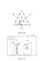
- FIGURE 10 The tentative Grey-code bit allocation that was carried out as described above has been illustrated in FIGURE 10 .
- This particular bit-code to symbol allocation has been used to compute the bit error rate from the symbol error rate when transmitting and receiving data in noise (see FIGURE 11 ).
- FIGURE 11 the curves of symbol error rate and bit error rate for the dimpled diamond constellation 800 of FIGURE 8 and the bit-code allocation of FIGURE 10 are compared to that of 64-V3AM, which had the same performance as triple 16QAM using either the aforementioned 4+4+4 or 4+(2,2) configurations with the same total transmitted power.
- the error rate is plotted versus the total transmitted signal power to noise ratio.
- This graph illustrates that the dimpled diamond constellation 800 produces a slightly lower symbol error rate than triple 16QAM, reflecting its slightly better d min -to-rms ratio, while having a slightly higher bit error rate due to the average number of bit errors per symbol error being about 1.5 times greater for each nearest-neighbor error event.
- this approximately 0.4dB loss is more than compensated by the ability to run the transmit power amplifier with 0.9db greater efficiency than the triple 16QAM of the 4+(2,2) constellation.
- the constellation coordinates and the numerical value of their pseudo-Grey bit-code assignments are given below in TABLE # 3.
- the diamond constellation 600 may be dimpled differently by insetting not only the six vertices, but also the 12 edge-centers.
- the inset points form an internal diamond constellation of order 2, as further described below, while 48 points remain on the surface of the larger dimpled diamond constellation 1200 which is shown in FIGURE 12 (note: a + marks the edge centers that have been inset).
- any two points may be omitted, for example two of the 48 points, in the interests of minimizing average transmitted power for the same d min .
- a base station 1300 with a receiver 1302 that decodes the radio signal in accordance with one embodiment of the present invention note: only the receiver's camponents-functions that are relevant to the present invention have been described herein.
- the receiver 1302 can employ a decoder 1304 (having a processor 1306 which implements processor-executable instructions from a memory 1308) that is similar to the decoder described in the aforementioned U.S. Patent Application Serial No. 12/035,970 except that the decoder 1304 is adapted to decode a diamond constellation as is described below in more detail with respect to FIGURES 14-16 .
- the receiver 1302 receives the radio signal and mitigates the effects of multi-path propagation between itself and the transmitter 902 by subtracting the influence of previously decoded symbols using a decision feedback technique together with an equalizer feedforward technique to mitigate the Intersymbol Interference caused by as-yet undecoded symbols in the radio signal (steps 1320 and 1322).
- the remaining radio signal depends on the two diamond-constellation symbols that are encoded into the real and imaginary parts, with noise and other potential impairments.
- the equalized signal is decoded by first hypothesizing one of the two diamond symbols, looking up its X, Y, Z coordinates, and subtracting its influence from the signal samples (step 1324).
- the modified signal samples after subtracting the hypothesized symbol then comprise a number of complex values that depend linearly on the X, Y, Z coordinates of the second symbol.
- Splitting the real and imaginary parts into separate equations yields substantially more equations than the three unknowns X, Y and Z, and the equations may therefore be solved in the least squares sense to obtain the values of X, Y and Z that best explain all of the modified signal values (step 1326).
- the resultant solution for the X, Y and Z coordinates are quantized to the nearest symbol in the constellation, which can be rapidly carried out according to the following technique:
- Steps 1-4 involve no multiplies and only a few subtractions. Quantizing an X, Y, Z value to the nearest of 64 constellation points is thus not significantly more difficult than for the aforementioned triple 16QAM case.
- each hypothesis of the first symbol produces a candidate decoding, and the selection between candidate decodings occurs by comparing metrics.
- the metrics are obtained by using both symbols of a candidate to compute the expected signal values, and calculating the metric as the sums square error between expected and actual signal values.
- the above least squares solution and the metric calculation take this into account, for example, by weighting the equations with the square root of the inverse correlation matrix (see also the aforementioned U.S. Patent Application Serial No. 12/035,970 ).
- the number of signal samples used to decode the transmission signal depends on the multipath channel delay profile and on the results of pre-equalizing. Generally, at least as many signal samples as the length of the code should be used. Alternatively, it should be appreciated that there are even more signal samples and thus more equations which can be solved when the radio signal is received by more than one diversity antenna at the receiver. This can be desirable since the greater the over-dimensioning of the equations being solved, then the more noise immunity is likely to result.
- the simplest decoding technique is by correlating four signal samples with each of the three length-4 codes to obtain three complex correlations. This results in six real equations which represents 2:1 over-dimensioning when it comes to solve for the X, Y, Z coordinates of a diamond symbol.
- using correlations with only the three codes may result in losing information, as a signal time shift due to a delayed multipath ray results in energy being present in the 4th code.
- correlating with all 4 codes has little utility when compared to just processing all four signal samples and solving eight real equations for X, Y and Z.
- multipath propagation is likely to result in information being present in more than four chips, so the number of signal samples processed can be greater than four.
- the noise is not white, or otherwise correlated from one signal sample to the next, it can be useful to process signal samples that do not depend on the X, Y, Z values sought. All this is explained as follows.
- Received signal samples R ⁇ 1 I ⁇ 1 + jQ ⁇ 1
- R ⁇ 2 I ⁇ 2 + jQ ⁇ 2
- R ⁇ 3 I ⁇ 3 + jQ ⁇ 3
- ⁇ Z ⁇ 2 Q ⁇ 2 A ⁇ 51. ⁇ X ⁇ 1 + A ⁇ 52. ⁇ Y ⁇ 1 + A ⁇ 53. ⁇ Z ⁇ 1 + A ⁇ 54. ⁇ X ⁇ 2 + A ⁇ 55. ⁇ Y ⁇ 2 + A ⁇ 56.
- ⁇ Z ⁇ 2 I ⁇ 3 A ⁇ 61. ⁇ X ⁇ 1 + A ⁇ 62. ⁇ Y ⁇ 1 + A ⁇ 63. ⁇ Z ⁇ 1 + A ⁇ 64.
- the least squares solution is only Maximum Likelihood however when the noise on each of the received values I1, Q1 I2, Q2, I3, Q3, I4, Q4... is uncorrelated and of the same variance. If not, then a weighted least-squares solution may be required which weights the squared error from each equation differently, or linearly combines the error from two equations before squaring. For instance, the correct weighting can be achieved by multiplying both sides of the previously mentioned matrix equation by the square root of the inverse of a noise correlation matrix.
- the noise correlation matrix has elements ij which are the expected or mean values of noise(i) x noise(j) and is a square matrix of size 8x8 if there are eight equations.
- the square root of the noise correlation matrix may be found by expressing it in the form: [E] [A] [E] # where [E] is a matrix of its eigenvectors and [A] is a diagonal matrix of the corresponding eigenvalues.
- the inverse square root is then found by replacing each element of [A] by the reciprocal of its square root.
- ⁇ Z ⁇ 2 Q ⁇ 1 A ⁇ 31. ⁇ X ⁇ 1 + A ⁇ 32. ⁇ Y ⁇ 1 + A ⁇ 33. ⁇ Z ⁇ 1 + A ⁇ 34. ⁇ X ⁇ 2 + A ⁇ 15. ⁇ Y ⁇ 2 + A ⁇ 16.
- ⁇ Z ⁇ 2 I ⁇ 2 A ⁇ 41. ⁇ X ⁇ 1 + A ⁇ 42. ⁇ Y ⁇ 1 + A ⁇ 43. ⁇ Z ⁇ 1 + A ⁇ 44. ⁇ X ⁇ 2 + A ⁇ 45. ⁇ Y ⁇ 2 + A ⁇ 46.
- equation no. 7 The result as can be seen in equation no. 7 is to append one or more zero rows to the A-matrix, extending it to from an 8x6 to a 9x6 for example. Now the noise correlation matrix would also be extended to 9x9, and the extra elements are non-zero. When the extended A-matrix is multiplied by the inverse square root of the noise correlation matrix, then the zero row becomes a non-zero row, with the result that the number of equations now to be solved in the least squares sense is larger.
- One desirable solution is to use all signal samples that depend in any way on the X, Y, Z coordinates of the two symbols to be decoded, plus all signal samples that do not depend on the X, Y, Z coordinates of any other unknown to be found, but which may bear noise or impairment correlated to the noise or impairment on the samples which do depend on the symbols to be found. Using this complete set of equations effectively uses all of the available information in the received signal.
- equation no. 8 would be calculated for each symbol hypothesis (X2, Y2, Z2).
- the matrix operations do not even necessarily have to be computed every code period, if the A-matrix elements and the noise correlation matrix change more slowly than once per symbol.
- the A matrix is the same for many symbols, then the same would be true for the B-matrix, and thus the product of B with the 64 symbol hypotheses can be done once and the stored results used for several code periods.
- FIGURE 17 there is shown a base station 1700 with a receiver 1702 that decodes a radio signal in accordance with another embodiment of the present invention (note: only the receiver's components-functions that are relevant to the present invention have been described herein).
- the mobile phone transmitter 902 generated the radio signal using the technique where a majority of the constellation points are on the surface of the diamond-shaped constellation that is defined in a three-dimensional space with coordinate axes X, Y and Z spaced by the boundary equation
- 1.
- the receiver 1702 has a decoder 1703 with a processor 1704 which implements processor-executable instructions from a memory 1706 to decode the received radio signal by:(a) determining a facet of the diamond shape constellation on or within which a transmitted data symbol lies (see step 1720); (b) determining a subset of points on the facet within which the symbol lies (step 1722); (c) determining the point within the subset lying closest to the received coordinate values of the transmitted symbol (step 1724); and (d) determining the transmitted symbol from the combination of the facet, the subset and the closest point (step 1726).
- the transmitted symbol can be determined by using a look-up table 1708 which is addressed by using the facet number, the subset number and the closest point number.
- the receiver 1302 is able to decode the received radio signal by using a processor 1306 which implements processor-executable instructions from a memory 1308 to perform the following steps: (a) hypothesizing the first of the constellation points and determining the second constellation point, given the hypothesized constellation point; (b) determining a metric describing how accurately the hypothesized constellation point and the associated determined second constellation point predict the received signal; and (c) comparing the metric for all possible hypotheses of the first constellation point and selecting the hypothesis having the best metric as the correct hypothesis, thereby decoding the radio signal.
- a processor 1306 which implements processor-executable instructions from a memory 1308 to perform the following steps: (a) hypothesizing the first of the constellation points and determining the second constellation point, given the hypothesized constellation point; (b) determining a metric describing how accurately the hypothesized constellation point and the associated determined second constellation point predict the received signal; and (c) comparing the metric for all possible hypotheses of the first constellation point and selecting
- diamond constellations of other sizes can be constructed as listed below, with an assumption of a sphere radius of 0.25/ ⁇ 2.
- the constellation of order N contains the constellation of order N-2 within it, and they are different points with different coordinates than the order N-1 constellation.
- the first diamond constellation 600 that was described above had a 85/66 point pattern of order 4 where only the 66 surface points were used with any two deleted. It was then discussed where it was advantageous to delete six surface points, e.g. the six vertices, and to replace them with the six points of the order 1 constellation, which are contained well within the outer points and do not violate minimum distance requirements.
- the diamond constellation 800 with depressed vertices was produced as shown in FIGURE 8 .
- a further dimpled diamond constellation 1200 was shown in FIGURE 12 , in which the vertices and edge-center points were inset, thereby producing an order-2 constellation which included 18 internal points.
- Many different variations can be produced and simulated, after allocating Grey coding as well as possible given the constellation, or allocating symbols to data in some other way depending on the application (e.g., PCM, speech, ASCII text etc). All such variations can be designed to limit the peak-to-rms ratio while preserving communications efficiency in accordance with the present invention.
- the present invention relates to a transmitter and a method for generating a radio signal with a reduced ratio of peak amplitude to root-mean-square amplitude which helps to improve the transmit efficiency of the transmitter's power amplifier.
- the method of communicating data symbols resulting in a transmitted signal with a reduced ratio of peak amplitude to root-mean-square amplitude includes the steps of:
Abstract
Description
- This application is related to United States Patent Application No.
12/166883 filed July 2, 2008 - The present invention relates in general to the wireless telecommunications field and, in particular, to a transmitter and a method for generating a radio signal with a reduced ratio of peak amplitude to root-mean-square amplitude which helps to improve the transmit efficiency of the transmitter's power amplifier. In addition, the present invention relates to a receiver that can decode the radio signal.
- The following abbreviations are herewith defined, at least some of which are referred to within the following description of the prior art and the present invention.
- CDMA
- Code-Division Multiple Access
- FIR
- Finite Impulse Response
- HSPA
- High-Speed Packet Access
- PA
- Power Amplifier
- PCM
- Pulse Code Modulation
- PSK
- Phase Shift Keying
- QAM
- Quadrature Amplitude Modulation
- UMTS
- Universal Mobile Telecommunications Service
- WCDMA
- Wideband Code-Division Multiple Access
- It is well known in the art that a communications signal such as a radio signal can be thought of as having an instantaneous complex value on a two-dimensional complex plane, where the coordinate in one dimension is the signed amplitude of a sinusoidal component of the radio signal and the coordinate in the second dimension is the signed amplitude of a cosinusoidal component of the radio signal. Since the cosine function and the sine function are mutually orthogonal functions, their correlation is zero, which means that the two dimensions are at right angles with respect to each other. The two dimensions are commonly labeled I and Q for "In-phase" and "Quadrature". No other orthogonal dimensions exist in this signal space, which is a plane. It is also well known that symbols representing groups of bits can be located on the I, Q plane such that any two symbols are sufficiently separated from one another to avoid confusion, so long as the signal-to-noise ratio is high enough. For example, 16 symbols can be located on a 4x4 grid known as 16QAM, and four binary bits assigned to each point. In 64QAM, 64 symbols can be located on a BX8 grid and 6 binary bits assigned to each point. Non-rectangular constellations of points can also be used, for example 16-PSK (phase shift keying) in which 16 points are equispaced in angle around a circle, and 4 binary bits are allocated to each of the points.
- In the prior art, it is generally considered to be desirable and known to allocate bit groups to symbol points according to a Grey coding scheme such that the bits assigned to adjacent points in the signal space differ in as few bit positions as possible, ideally in only one bit position. A brief discussion is provided next about some of these well known schemes and their drawbacks that are associated with the prior art.
-
US Patent No. 4,084,137, filed August 24, 1976 , describes a 4-dimensional modulation scheme in which both radio wave polarizations are used to provide two independent channels, where each channel is capable of carrying a two-dimensional signal. In this patent, there is reference to an IEEE paper entitled "Digital Transmission with Four Dimensional modulation" (Trans IEEE on Information Theory, July 1974, pp. 497-502) in which there is described a four dimensional modulation scheme that is constructed to have a peak energy constraint. The peak energy constraint was described therein to mean that the sum of the powers in the two polarizations should not exceed some maximum value. For instance, if (11, Q1) are the In-phase and Quadrature Phase components on one polarization and (I2,Q2) are the In-phase and Quadrature Phase components on the other polarization, then the total energy or power which is constrained is given by I12+Q12+I22+Q22. This is a relevant and adequate constraint when (I1,Q1) and (I2,Q2) are separately generated and applied to physically independent channels, such as orthogonally polarized antennas. However, if (I1,Q1) and (I2,Q2) are not separately generated and not applied to physically separate channels, but instead are applied to the same physical channel, then the transmitted signal would be (Il+I2,QI+Q2) and its energy or power would be proportional to (Il+I2)2 + (Q1+Q2)2, which is not constrained by the same metric. Thus a different scheme is needed in order to constrain the peak energy in the latter case. -
US Patent No. 4,597,090, filed April 14, 1983 , discloses a modulation scheme for a single physical channel in which the two dimensions in signal space (I,Q) on m sequential signal samples are considered to form a 2m dimensional space, and where mN data bits are encoded into the 2m dimensions in such a way as to obtain a coding gain by constraining the selection of I,Q value of one signal sample to depend on the selection of I,Q values for the other signal samples. This is a form of Trellis Coding, and is related to obtaining a coding gain but is silent about obtaining a reduction of the peak-to-rms ratio of the radio signal which is a subject that is related to the present discussion. - The 3rd Generation cellular system known as WCDMA or UMTS, currently has a method under specification known as HSPA which enables the transmission of higher data rates from a mobile phone to a network (or base station). The HSPA transmission uses an approach called "Multi-code CDMA". In this Multi-code CDMA system, each data symbol is spread out in time and spectrum by combining it with a spreading code. On the downlink (base station to mobile phone), the codes used to transmit signals from the base station are coordinated at the base station so that they are mutually orthogonal. In contrast, in the uplink (mobile phone to base station), the coordination needed between different mobile phones to achieve orthogonality is considered too difficult to implement, so each mobile phone uses a different random code sequence.
- However, at each mobile phone, it is still possible to generate several random code sequences that are coordinated among themselves to be mutually orthogonal. Each of these orthogonal codes may then carry a symbol sub-stream so that the combined symbol stream rate is enhanced. But, in this situation, the mobile phone's available transmitter power is going to be divided between the different codes which means that the range over which each sub-stream may be successfully received and decoded error free is going to be reduced. In fact, the reduction of power per each sub-stream in a multi-code modulation signal transmitted, from a mobile phone is worse than would be expected by merely dividing the transmitter power by the total number of sub-streams. This is because it is not so much the average power that is constrained by battery voltage, but rather the peak signal amplitude, which happens to be limited by the battery voltage.
- Thus, in the 3rd Generation cellular system there is a desire for a modulation scheme which develops the greatest mean power per each sub-stream within a constraint of the composite peak signal amplitude of all sub-streams. For example, if the mobile phone used a three-code multicode scheme with three length=4 codes where each code carried a sub-stream of 16QAM symbols at similar amplitude, then the total mean power that is transmitted within a given peak amplitude constraint is 7 32dB below the peak before filtering to contain the spectrum, and the mean power per sub-stream is 12.1dB below the peak. Filtering generally increases the peak-to-rms ratio further. The HSPA standard describes an improvement over the three length=4 spreading code scheme since it specifies a length=2 code of twice the power (√2 times the amplitude) which carries two symbols in the same time period that a superimposed and orthogonal length=4 code carries a third symbol, which effectively achieves the same symbol rate as three length=4 codes. This 4+(2,2) configuration is able to develop a total mean power which is 5.44dB below the peak, and is 1.88dB more effective than the 4+4+4 configuration that is associated with the three length=4 spreading code scheme.
- However, with the 4+(2,2) configuration there is a reduction of the spreading factor, which is merely a move in the direction of no spreading which also achieves a low peak-to-rms ratio, but the resulting radio signal becomes very difficult to decode when there is a significant amount of multipath channel distortion. In view of the foregoing, it can be seen that there has been and is still a need for a transmitter and a method that can address the aforementioned shortcomings and other shortcomings associated with the prior art. These needs and other needs are addressed by the transmitter and the method of the present invention.
- In one aspect, the present invention provides a method for reducing a peak-to-rms ratio in a transmitted radio signal while placing a limit on the peak composite symbol amplitude when utilizing multi-dimensional modulation. The method includes the steps of: (a) encoding information into a stream of binary bits; (b) forming a plurality of groups of bits from the stream of binary bits, wherein the plurality of groups of bits represent a plurality of data symbols; (c) representing each data symbol by a set of coordinates in a multidimensional space, wherein a number of dimensions in the multidimensional space correspond to a number of at least three orthogonal components which eventually comprise the transmitted radio signal; and (d) choosing coordinates for each data symbol such that each data symbol is located at a minimum distance away from a nearest other data symbol in the multidimensional space and also such that the peak composite symbol amplitude to root-mean-square amplitude of the transmitted radio signals is minimized. This method of generating a radio signal with a reduced ratio of peak amplitude to root-mean-square amplitude helps to improve the transmit efficiency of a transmitter's power amplifier.
- In another aspect, the present invention provides a method of communicating data symbols resulting in a transmitted signal with a reduced ratio of peak amplitude to root-mean-square amplitude. The method includes the steps of:
- (a) simultaneously using multiple, additively-combined, spread-spectrum codes each carrying an In-phase or real signal value and a Quadrature phase or imaginary signal value to provide at least three independent modulation dimensions, each dimension carrying a coordinate value; and (b) defining a set of constellation points to be associated with the data symbols, the constellation points distributed within a space comprised of the at least three dimensions such that a Euclidean distance between any two of the constellation points is not less than a desired minimum and such that a desired peak amplitude value is not exceeded by any point, the peak value being determined by any of the following measures: (i) a sum of absolute values of the coordinates of any constellation point corresponding to the dimensions provided by the real signal values carried by the multiple, additively-combined, spread-spectrum codes; (ii) a sum of the absolute values of the coordinates of any constellation point corresponding to the dimensions provided by the imaginary signal values carried by the multiple, additively-combined, spread-spectrum codes; and (iii) a sum of the squares of (a) the sum of the absolute values of the coordinates of any constellation point corresponding to the dimensions provided by the real signal values carried by the multiple, additively-combined, spread-spectrum codes; and (b) the sum of the absolute values of the constellation coordinates of any point corresponding to the dimensions provided by the imaginary signal values carried by the multiple, additively-combined, spread-spectrum codes. This method of generating a radio signal with a reduced ratio of peak amplitude to root-mear-square amplitude helps to improve the transmit efficiency of a transmitter's power amplifier.
- In still yet another aspect, the present invention provides a transmitter that reduces a peak-to-rms ratio in a radio signal while placing a limit on the peak composite symbol amplitude when utilizing multi-dimensional modulation. The transmitter includes: (a) an encoder that divides groups of data bits into a first subgroup and a second subgroup; (b) the encoder uses the first subgroup of bits to select one of a number of constellation points that are distributed within a first multi-dimensional space, where a location of the constellation points have been determined such that a sum of their coordinates is less than a desired maximum value, where the coordinates of the selected constellation point are used to set values of real parts of corresponding complex numbers; (c) the encoder uses the second subgroup of bits to select another one of a number of constellation points that are distributed within a second multidimensional space, where a location of the constellation points have been determined such that a sum of their coordinates is less than a desired maximum value, where the coordinates of the selected constellation point are then used to set values of imaginary parts of corresponding complex numbers; (d) the encoder pairs one real and one imaginary part to form a complex number and the remaining real and imaginary parts are paired likewise to obtain a set of complex numbers; (e) the encoder assigns the complex numbers to be multiplied by an associated one of a number of multi-chip orthogonal codes, where products of each complex number with its code are subsequently added chip-wise to obtain a multi-code symbol; (f) a filter that receives a stream of the multicode symbols and filters them to constrain a transmitted spectrum; (g) a modulator that modulates the filtered signal with a radio frequency carrier; and (h) an antenna that transmits the modulated radio signal. Thus by generating a radio signal with a reduced ratio of peak amplitude to root-mean-square amplitude the transmit efficiency of the transmitter's power amplifier is improved.
- In yet another aspect, the present invention provides a receiver that decodes a radio signal which has a reduced peak-to-rms ratio and a limited peak composite symbol amplitude. In one embodiment, the receiver includes a decoder with a processor that implements processor-executable instructions from a memory to decode the radio signal by: (a) determining a facet of a diamond-shaped constellation on or within which a data symbol of the radio signal lies; (b) determining a subset of points on the facet within which the data symbol of the radio signal lies; (c) determining a point within the subset of points which is closest to coordinate values of the data symbol; and (d) determining the data symbol from the combination of the facet, the subset of points, and the closest point.
- In still yet another aspect, the present invention provides a receiver that decodes a radio signal which has a reduced peak-to-rms ratio and a limited peak composite symbol amplitude. In one embodiment, the receiver includes a decoder with a processor that implements processor-executable instructions from a memory to decode the radio signal by: (a) hypothesizing a first of multiple constellation points on a first diamond-shaped constellation where the first constellation point is associated with a data symbol of the radio signal; (b) determining, given the hypothesized first constellation point, a second constellation point on a second diamond-shaped constellation where the second constellation point is associated with a data symbol of the radio signal; (c) determining a metric describing how accurately the hypothesized first constellation point and the associated determined second constellation point predict the received radio signal; and (d) comparing the metric for all possible hypotheses of the first constellation point and selecting the hypothesis having the best metric as the correct hypothesis, thereby decoding the radio signal.
- Additional aspects of the invention will be set forth, in part, in the detailed description, figures and any claims which follow, and in part will be derived from the detailed description, or can be learned by practice of the invention. It is to be understood that both the foregoing general description and the following detailed description are exemplary and explanatory only and are not restrictive of the invention as disclosed.
- A more complete understanding of the present invention may be obtained by reference to the following detailed description when taken in conjunction with the accompanying drawings:
-
FIGURE 1 is a diagram of atraditional HSPA 4+(2,2) multicode cellular system which is used to help explain the present invention; -
FIGURE 2 is a diagram of showing the 16 points of a 16QAM constellation which is used to help explain the present invention; -
FIGURE 3 illustrates diagrams associated with a traditional 4+4+4 multicode cellular system which is used to help explain the present invention; -
FIGURE 4 is a diagram that visually depicts the 45 degree phase rotation of 16QAM symbols modulated on to a length=4 code relative to 16QAM symbols modulated on to a length=2 code of double the power (√2 times the amplitude) which is used to help explain the present invention; -
FIGURE 5 is a graph that depicts a +++ plane for I1, I2, I3 when +I1+I2+I3 = 1 which is used to help explain the present invention; -
FIGURE 6 is a diagram that depicts a diamond-shaped constellation which is used to help explain the present invention; -
FIGURE 7 are diagrams illustrating different ways six dimensions I1 Q1, I2, Q2, I3 and Q3 can be grouped to form multi-dimensional symbols which are used to help explain the present invention; -
FIGURE 8 is a diagram that depicts a diamond-shaped constellation which has depressed vertices that is used to help explain the present invention; -
FIGURE 9 is a block diagram of a mobile phone with a transmitter that is configured in accordance with an embodiment of the present invention; -
FIGURE 10 is a diagram illustrating a Grey-code assignment of 6-bit groups to the diamond constellation shown inFIGURE 8 which is used to help explain the present invention; -
FIGURE 11 is a graph illustrating an error rate versus a total transmitted signal power to noise ratio which is used to help explain the present invention; -
FIGURE 12 is a diagram that depicts a dimpled diamond-shaped constellation which is used to help explain the present invention; -
FIGURE 13 is a block diagram of a base station with a receiver that is configured in accordance with an embodiment of the present invention; -
FIGURES 14-16 are diagrams which are used to help explain how the receiver shown inFIGURE 13 decodes a radio signal in accordance with one embodiment of the present invention; and -
FIGURE 17 is a block diagram of a base station with a receiver that is configured in accordance with another embodiment of the present invention. - The present invention includes a transmitter (e.g., incorporated within a mobile phone) and a method that reduces the peak-to-rms ratio in a radio signal while placing a limit on the peak composite symbol amplitude when utilizing multi-dimensional modulation. In particular, the transmitter encodes information into a stream of binary bits and groups of bits are combined to be represented by data symbols. Then, each data symbol is represented by a set of coordinates in a multidimensional space, where the number of dimensions in the multidimensional space correspond to at least three orthogonal components which will comprise the transmitted radio signal. The coordinates of each data symbol are chosen such that each data symbol is located at a minimum distance away from the nearest other data symbol in the multidimensional space and also such that the peak amplitude to root-mean-square amplitude of the transmitted radio signal is minimized. A detailed discussion about different ways the present invention can be implemented is provided after describing in more detail the aforementioned traditional three-code multicode scheme which has the 4+4+4 configuration and the aforementioned traditional HSPA three-code multicode scheme which has the 4+(2,2) configuration.
- Referring to
FIGURE 1 , there is a block diagram of a traditional HSPA three-code multicodecellular system 100 where amobile phone 102 has atranmsitter 108 that transmits a radio signal with three 16QAM symbols S1, S2 and S3 per each 4-chip modulation period to abase station 104. As shown, a length=2 code is repeated twice and used to carry two 16QAM symbols S2 and S2 successively, while a length=4 code, orthogonal to the length=2 code is additively superimposed and used to carry a third 16QAM symbol S1 during the same 4-chip period. A 16QAM symbol constellation has the general form shown inFIGURE 2 . Each 16QAM symbol S1 S2 and S3 carries 4 bits so with three symbols S1 S2 and S3 there are 12 bits conveyed in the 4-chip time interval, representing 22 = 4096 possibilities. Thus, the decoding at thebase station 104 can include testing all 4096 possibilities (the "brute force" method") or may use the reduced complexity method disclosed in co-assignedU.S. Patent Application Serial No. 12/035,970 filed February 22, 2008 and entitled "Efficient Multimode Detection", the contents of which are incorporated by reference herein. - Communicating using 16QAM symbols comprises transmitting 2 bits on each of the I and Q components of a signal, the bits being equispaced about zero in each of the two dimensions of the complex signal plane. Thus, the I-component may take on values of +1.5, +0.5, -0.5 and -1.5 while the Q-component does likewise independently.
FIGURE 2 shows the 16 possible signal points which are located in the I, Q plane at the intersections of a regular, rectangular grid. The peak-to-rms ratio of a single 16QAM symbol may be calculated by determining the peak amplitude and the root-mean-square value. The peak amplitude occurs when both I and Q take on their maximum amplitude of +/-1.5 at the same time, giving a net vector length of 1.5√2, whereas the root-znean-square value is calculated by averaging the square of the amplitude over all 16 points, wherein there are 4 corner points, each with a square amplitude value (1.5√2)2 = 4.5; 8 points on the sides each of square amplitude (1.52+0.52) = 2.5, and four points in the riddle of square amplitude (0.5√2)2 = 0.5. The average of these points is (4x4.5 + 8x2.5 + 4x0.5) /16 = 2.5. Thus the rms value is √2.5 or 1.58. The peak-to-rms amplitude ratio is thus 1.5√2 / √2.5, which in decibels is 2.55dB. - For the modulation of
FIGURE 1 however, it can be seen that two I values and two Q values are going to overlap in each chip period. The I-value of the length=4 code may be one of the four values 1.5, 0.5, -0.5, -1.5, but the I-values of the length=2 code are √2 times larger. The Q-values are scaled likewise. Thus, applying the same procedure as above to calculate peak-to-rms ratio gives the answer 5.44dB for this type of multi-code modulation as mentioned in the background section. If, on the other hand, the three length=-4 codes of the traditional 4+4+4 configuration shown inFIGURE 3 had been used, then the I-values for each would have been any of the values 1.5, 0.5, -0.5 or 1.5, giving a peak 1-value of 4.5 and a peak Q-value likewise, or a peak amplitude of I and Q combined of 4.5√2. The rms value however is just √3 times the rms value of a single 16QAM transmission which was calculated above to be √2.5. Thus, the peak-to-rms ratio of three length=4 codes superimposed is thus 4.5√2 / (√3 x √2.5) = 2.32 or 7.32dB, as also mentioned in the background section. Therefore, when peak amplitude is limited, the 4+(2,2) configuration ofFIGURE 1 is preferable to the 4+4+4 code configuration ofFIGURE 3 . - The mobile phone's
transmitter 108 also has apower amplifier 106 that generates a mean power output without distortion that depends on the peak-to-rms ratio of the signal in addition to other factors. For a class-B power amplifier 106, the maximum non-distorting efficiency occurs when it happens to be generating maximum power where the maximum efficiency is defined as follows:

- On the other hand, the mean efficiency with a varying amplitude signal is defined as follows:


- Also, the power consumption of a class-
B power amplifier 106 with zero quiescent bias happens to be proportional to the output signal amplitude. Therefore, the mean DC power consumption is equal to the peak power consumption times the ratio of mean amplitude to peak amplitude, which, normalized to unity load resistance, gives the following:

- Combining the equations 1b, 2c and 3b results in the following:

- While ηmax is a power amplifier implementation-dependent quantity, the value peak-to-rms amplitude ratio x mean-to-rms amplitude ratio is a characteristic of the modulation. For maximum power amplifier efficiency, therefore, one would like to minimize the latter quantity. Another modulation performance measure is the ease or difficulty with which two different symbols may be confused by the
base station 104 . This modulation performance measure is determined by the minimum distance dmin, which is the Euclidean distance in signal space between the two symbols that are closest together. Generally, if a single pair of symbols lay closer to one another in signal space than any other pair, then they would be separated in an attempt to obtain a more equal spacing with a larger dmin. To compare different modulations in this respect, dmin should be normalized to the same rms signal value, that is to the same mean transmitted power. Thus, the quantity dmin/(rms amplitude) is a measure of communications efficiency while η is a measure of the transmitter'spower amplifier 106 efficiency. When maximizing the latter, it is desirable that the former should preferably be maintained, and not significantly degraded. This is accomplished by the present invention. - Referring again to the HSPA triple-16QAM modulation shown in
FIGURE 1 , one way to obtain a slight (0.5dB) reduction in peak-to-rms amplitude ratio without altering the communications efficiency is to rotate the 16QAM constellation on the length=4 code by 45 degrees relative to that on the length=2 code, as shown inFIGURE 4 . This particular rotation scheme was disclosed in the above-mentionedU.S. Patent Application No. 12/166,883 that is entitled "Reduced Peak-to-RMS Ratio Multicode Signal" (Attorney Docket No. P25701). In the above-mentionedU.S. Patent Application No. 12/166,883 (Attorney Docket No. P25701), it was also shown that improvements in peak-to-rms ratio of different modulation method/schemes, determined before spectrally limiting filtering, tended to give the same improvement after filtering, although spectral limiting increased the peak-to-rms ratio for all of the tested modulations. In view of this, the present invention is directed to a method for achieving peak-to-rms ratio reductions which are determined before spectral limiting filtering, with the expectation that this will translate into similar peak-to-mean ratio reductions when comparing waveforms subject to spectral limiting filtering. The new method aims to avoid reducing the communications efficiency factor dmin/rms and also avoids reducing the spreading factor, so as to retain a good tolerance of multipath distortion while using transmitter equalizers of reasonable complexity. A detailed discussion is provided below about how this new method can be implemented in accordance with the different embodiments of the present invention. - Referring back to the three-code multicode scheme shown in
FIGURE 3 , it can be seen that three 16QAM symbols S1, S2 and S3 can be regarded as six 4-AM symbols, each 4-AM symbol carrying two bits of information with its four possible signal points, and occupying one of six dimensions I1, Q1, I2, Q2, I3 and Q3. As shown, the pairs of (I,Q) dimensions are orthogonal by virtue of being 90 degrees out of phase, while the use of orthogonal codes allows three such pairs of I,Q values to be conveyed using all six dimensions I1, Q1, I2, Q2, I3 and Q3, which are orthogonal to each other when the codes are mutually orthogonal. Absent signal distortion in the transmission, the six dimensions I1,Q1 12, Q2, I3 and Q3 are truly independent inasmuch as they do not interfere with one another, and also the receiver noise has a nominally equal rms value that is nominally uncorrelated between any pair of the dimensions I1, Q1, I2, Q2, 13 or Q3. However, the six dimensions I1, Q1, I2, Q2, I3 and Q3 are not independent as far as the mobile phone'stransmitter 108 is concerned, as the values I1, I2, I3 and likewise the values Q1, Q2, Q3 add linearly and not quadratically. Thus the transmitted signal amplitude is as given by the following (seecode 1,code 2 andcode 3 inFIGURE 3 ):Chip 1Chip 2Chip 3Chip 4 Itransmit = I1+I2+I3 Il+12-13 I1-I2+I3 II-T2-I3 Qtransmit = Q1+Q2+Q3 Q1+Q2-Q3 Q1-Q2+Q3 QI-Q2-Q3 - The above shows that, since all sign combinations of I1, I2 and I3 are tested across the four chips, they will be additive in some chip whatever their signs to produce the peak value in that chip. Unless otherwise constrained, the worst case is when the peak of I and the peak of Q happen to take place in the same chip.
- If the I and Q signals are of the same form, then it follows that the peak-to-rms ratio of the transmit amplitude is the same as the peak-to-rms ratio of I or Q alone where the combination of I and Q merely increase both the peak and the rms by √2 alike when compared to the ratio for I or Q alone. Therefore, seeking a modulation scheme with a low peak-to-rms ratio on I and Q alone can produce a low peak-to-rms for the combined transmit signal. Thus, it is desirable that none of I1+I2+I3, I1+I2-I3, I1-I2+I3 and I1-I2-I3 exceed some desired peak value, which can be arbitrarily chosen to be 1 . 0 . These four constraints can be expressed by |I1|+|I2|+|I3| < or = 1 with the boundary being set to 1.
- This boundary comprises 8 planes, corresponding to each of the two possible signs + or - which each of the three values I1, I2 and I3 could have. For example, the +++ plane for I1, I2, I3 when they are all positive is given by +Il+I2+I3 = 1 and is shown in
FIGURE 5 . InFIGURE 5 , the transition from I1, I2, I3 notation to the conventional 3-D coordinates X, Y, Z has also been introduced. - When the 8 planes corresponding to all 8 sign combinations are drawn, the result is a
diamond shape 600 which is shown inFIGURE 6 . In order to represent the three pairs of bits carried by the three signals I1, I2 and I3 belonging to the original three 16QAM symbols, a total of 64 possible points needs to be located on or within thediamond shape 600. An example of a regular spacing yielding a total of 66 points has been shown in thediamond shape 600 where two points may therefore be omitted. The 66 points include: - ○ 6 vertices where one coordinate is +/-1 and the other two coordinates are zero (total of 6 points).
- ○ 12 edges where one coordinate is zero and the other two are + or -. The edge center points have non-zero coordinates +/-0.5 while the other two points on each edge have non-zero coordinates (+/-0.25, +/-0.75) or vice versa giving a total of 36 points.
- ○ 8 facets corresponding to the planes |X|+|Y|+|Z|=1, each triangular facet having a triangle of three points in its center. The coordinates of these points have coordinates 0.5, 0.25, 0.25 (the sum of which is unity) permuted in every way between X, Y and Z and with all possible +/- signs for a total of 24 points.
- The minimum distance dmin of this constellation is 0.25√2 = 0 . 3535 .
- The rms value for this particular constellation may be calculated in the same way as was carried out above with the 16QAM constellation (see
FIGURE 3 ). However, to be able to compare this performance with the 16QAM performance, the six dimensions ofFIGURE 6 first need to be grouped to form two three-dimensional symbols comparable to the two 3-dimensional symbols FIGURE 7 . -
FIGURE 7 suggests that the six dimensions I1, Q1, I2, Q2, I3 and Q3 can be conceptually grouped in any desired way, for example, as six 4-AM symbols (FIGURE 3 ), as three16QAM symbols D symbols - The following
TABLE # 1 compares the properties of the 64-V3AM constellation (I1, I2, I3) with thediamond constellation 600 ofFIGURE 6 , where two points have been omitted.TABLE # 164-V3AM Diamond Const. Peak-to-rms ratio 7.32dB 2.75dB dmin-to-rms ratio -8.75dB -9.29dB PA efficiency loss -3.21dB -1.12dB - It can be seen that the
diamond constellation 600 achieves the desirable reduction of 4.57dB in the peak-to-rms ratio and a 2dB improvement in the power amplifier (PA) efficiency at the expense of a small reduction of 0.44dB in the minimum distance. The latter can, however, be mitigated by depressing the vertices of the diamond from a non-zero coordinate of 1.0 to a non-zero coordinate of +/-0.25 (for example) with the following results:TABLE # 264-V3AM Diamond Const. Peak-to-rms ratio 7.32dB 3.53dB dmin-to-rms ratio -8.75dB -8.51dB PA efficiency loss -3.21dB -1.43dB - By depressing the vertices, the rms value is reduced, which improves the dmin, however the peak remains the same, so the peak to rms-ratio is only slightly higher. This is a more desirable result, as the mean transmitter power consumption for the same symbol error rate will be lower. The shape of a 3-
dimensional constellation 800 which has depressed vertices is shown inFIGURE 8 . Other modifications to thediamond constellation 600 as well as other diamond constellations which are within the same family are discussed in detail below after discussing one embodiment of the mobile phone's transmitter in accordance with the present invention. - Referring to
FIGURE 9 , there is shown a mobile phone 900 with atransmitter 902 that reduces the peak-to-rms ratio in a radio signal while placing a limit on the peak composite symbol amplitude when utilizing multi-dimensional modulation in accordance with one embodiment of the present invention (note: only the transmitter's components-functions that are relevant to the present invention have been described herein) . Basically, the transmitter 902 (e.g., multicode transmitter 902) can realize the reduced peak-to-rms amplitude ratio with a limited peak composite symbol amplitude using: - (i) An
encoder 904 that divides groups of data bits, e.g. 12 bits, into a first subgroup (e.g., 6 bits) and a second subgroup (e.g., 6 bits). - (ii) The
encoder 904 takes the first subgroup of bits and selects one of a number of constellation points that are distributed within a first multi-dimensional space (e.g. the 3-dimensional space X, Y, Z), where the location of the constellation points have been determined such that the sum of their coordinates is less than a desired maximum value. The coordinates of the selected constellation point are then used to set the values of the real parts of corresponding complex numbers, the real part of each complex number thus corresponding to the value of an associated coordinate. - (iii) The
encoder 904 takes the second subgroup of bits and selects another one of a number of constellation points that are distributed within a second multidimensional space (e.g. the 3-dimensional space X, Y, Z), where the location of the constellation points have been determined such that the sum of their coordinates is less than a desired maximum value. The coordinates of the selected constellation point are then used to set the values of the imaginary parts of corresponding complex numbers, the imaginary part of each complex number thus corresponding to the value of an associated coordinate. - (iv) The
encoder 904 pairs one real and one imaginary part to form a complex number and the remaining real and imaginary parts are paired likewise to obtain a set of complex numbers. If one multidimensional space has more dimensions than the other, then one or more real or imaginary part may not be paired, resulting in one or more non-complex numbers which are either purely real or purely imaginary. - (v) The
encoder 904 assigns the numbers obtained above to be multiplied by an associated one of a number of multi-chip orthogonal codes. The products of each number with its code are then added chip-wise to obtain a multi-code symbol comprising a sequence of in general complex-valued chips. - (vi) A filter 906 (e.g., root-Nyquist filter 906) receives a stream of the multicode symbols and filters them to constrain the transmitted spectrum.
- (vii) A
modulator 908 which modulates the filtered signal with a radio frequency carrier. - (viii) An
antenna 910 which transmits the modulated radio signal. - It is considered desirable to associate bit groups with constellation points in steps (ii) and (iii) such that neighboring constellation points differ in as few bit positions as possible, preferably only one. This so-called Grey coding works well for 4-AM, 16QAM, 64V3-AM etc... since in each dimension the bit pairs are distributed in the
order point diamond constellation - Perfect Grey coding is not always possible, but an example of an attempt at a Grey-code assignment of 6-bit groups to the
diamond constellation 800 is shown inFIGURE 10. FIGURE 10 is looking down on thediamond constellation 800 with one vertex (X=1), which is assigned the code 000000, in the middle and the projection of the four triangular facets having the center point (code 000000) as a common vertex are visible. The four facets on the back side away from the viewer have been folded out and their projections form an outer square, the corners of which are all the same point, which is assigned thecode 110110, and is the antipodal vertex to the vertex 000000 in the center of the diagram. Due to unfolding of the back-side facets, some edges (e.g. theline comprising codes - In this example, the six-bit groups are considered as 3+3 bit groups, and each subgroup of 3 bits may be incremented in Grey-code order along one set of lines and the other 3-bit group incremented in Grey-code order along the set of lines at right angles to the first set. This would achieve perfect Grey-coding if the
diamond constellation 800 was an 8x8 rectangular grid, but due to the mirror-imaging of sides of the unfolded facets, as described above, some non-Grey clashes occur at the edges. - For example, although edge-
code 011110 differs by only one bit fromadjacent code 011101 at point 53, it differs by three bits from code 101111 at point 54. This is because, when the back-side facets are folded into their proper positions,code 011110 is adjacent to both points 53 and 54, and cannot be only 1-bit different from both of their assigned codes. As long as these are a small fraction of the total number of pairs of neighboring points, however, the effect on mean Hamming distance is small. - The tentative Grey-code bit allocation that was carried out as described above has been illustrated in
FIGURE 10 . This particular bit-code to symbol allocation has been used to compute the bit error rate from the symbol error rate when transmitting and receiving data in noise (seeFIGURE 11 ). As shown inFIGURE 11 , the curves of symbol error rate and bit error rate for thedimpled diamond constellation 800 ofFIGURE 8 and the bit-code allocation ofFIGURE 10 are compared to that of 64-V3AM, which had the same performance as triple 16QAM using either the aforementioned 4+4+4 or 4+(2,2) configurations with the same total transmitted power. InFIGURE 11 , the error rate is plotted versus the total transmitted signal power to noise ratio. This graph illustrates that thedimpled diamond constellation 800 produces a slightly lower symbol error rate than triple 16QAM, reflecting its slightly better dmin-to-rms ratio, while having a slightly higher bit error rate due to the average number of bit errors per symbol error being about 1.5 times greater for each nearest-neighbor error event. However, this approximately 0.4dB loss is more than compensated by the ability to run the transmit power amplifier with 0.9db greater efficiency than the triple 16QAM of the 4+(2,2) constellation. The constellation coordinates and the numerical value of their pseudo-Grey bit-code assignments are given below inTABLE # 3.TABLE #3 Point Code X Y Z 1 0 0.25 0.00 0.00 2 6 0.00 0.25 0.00 3 51 0.00 0.00 0.25 4 54 -0.25 0.00 0.00 5 46 0.00 -0.25 0.00 6 48 0.00 0.00 -0.25 7 16 0.25 0.00 0.75 8 49 -0.25 0.00 0.75 9 20 0.00 0.25 0.75 10 17 0.00 -0.25 0.75 11 52 -0.25 0.00 -0.75 12 56 0.25 0.00 -0.75 13 57 0.00 -0.25 -0.75 14 60 0.00 0.25 -0.75 15 4 0.75 0.25 0.00 16 1 0.75 -0.25 0.00 17 8 0.75 0.00 0.25 18 32 0.75 0.00 -0.25 19 62 -0.75 -0.25 0.00 20 22 -0.75 0.25 0.00 21 50 -0.75 0.00 -0.25 22 55 -0.75 0.00 0.25 23 7 0.25 0.75 0.00 24 14 -0.25 0.75 0.00 25 15 0.00 0.75 0.25 26 39 0.00 0.75 -0.25 27 38 -0.25 -0.75 0.00 28 2 0.25 -0.75 0.00 29 34 0.00 -0.75 -0.25 30 10 0.00 -0.75 0.25 31 5 0.50 0.50 0.00 32 3 0.50 -0.50 0.00 33 24 0.50 0.00 0.50 34 40 0.50 0.00 -0.50 35 41 0.25 -0.25 -0.50 36 30 -0.50 0.50 0.00 37 44 0.25 0.25 -0.50 38 53 -0.50 0.00 0.50 39 29 0.00 0.50 0.50 40 45 0.00 0.50 -0.50 41 27 0.00 -0.50 0.50 42 43 0.00 -0.50 -0.50 43 12 0.50 0.25 0.25 44 36 0.50 0.25 -0.25 45 9 0.50 -0.25 0.25 46 33 0.50 -0.25 -0.25 47 58 -0.50 -0.25 -0.25 48 18 -0.50 -0.25 0.25 49 63 -0.50 0.25 -0.25 50 23 -0.50 0.25 0.25 51 13 0.25 0.50 0.25 52 37 0.25 0.50 -0.25 53 31 -0.25 0.50 0.25 54 47 -0.25 0.50 -0.25 55 42 -0.25 -0.50 -0.25 56 26 -0.25 -0.50 0.25 57 35 0.25 -0.50 -0.25 58 11 0.25 -0.50 0.25 59 28 0.25 0.25 0.50 60 25 0.25 -0.25 0.50 61 21 -0.25 0.25 0.50 62 19 -0.25 -0.25 0.50 63 59 -0.25 -0.25 -0.50 64 61 -0.25 0.25 -0.50 - If desired, the
diamond constellation 600 may be dimpled differently by insetting not only the six vertices, but also the 12 edge-centers. The inset points form an internal diamond constellation oforder 2, as further described below, while 48 points remain on the surface of the largerdimpled diamond constellation 1200 which is shown inFIGURE 12 (note: a + marks the edge centers that have been inset). For transmitting 6 bits per symbol, any two points may be omitted, for example two of the 48 points, in the interests of minimizing average transmitted power for the same dmin. A more detailed discussion about diamond constellations is provided below after a detailed discussion about how a receiver decodes the radio signal in accordance with several different embodiments of the present invention. - Referring to
FIGURE 13 , there is shown abase station 1300 with areceiver 1302 that decodes the radio signal in accordance with one embodiment of the present invention (note: only the receiver's camponents-functions that are relevant to the present invention have been described herein) . If desired, thereceiver 1302 can employ a decoder 1304 (having aprocessor 1306 which implements processor-executable instructions from a memory 1308) that is similar to the decoder described in the aforementionedU.S. Patent Application Serial No. 12/035,970 except that thedecoder 1304 is adapted to decode a diamond constellation as is described below in more detail with respect toFIGURES 14-16 . - In one embodiment, the
receiver 1302 receives the radio signal and mitigates the effects of multi-path propagation between itself and thetransmitter 902 by subtracting the influence of previously decoded symbols using a decision feedback technique together with an equalizer feedforward technique to mitigate the Intersymbol Interference caused by as-yet undecoded symbols in the radio signal (steps 1320 and 1322). As a result, the remaining radio signal depends on the two diamond-constellation symbols that are encoded into the real and imaginary parts, with noise and other potential impairments. Then, the equalized signal is decoded by first hypothesizing one of the two diamond symbols, looking up its X, Y, Z coordinates, and subtracting its influence from the signal samples (step 1324). The modified signal samples after subtracting the hypothesized symbol then comprise a number of complex values that depend linearly on the X, Y, Z coordinates of the second symbol. Splitting the real and imaginary parts into separate equations yields substantially more equations than the three unknowns X, Y and Z, and the equations may therefore be solved in the least squares sense to obtain the values of X, Y and Z that best explain all of the modified signal values (step 1326). The resultant solution for the X, Y and Z coordinates are quantized to the nearest symbol in the constellation, which can be rapidly carried out according to the following technique: - 1. Form the modulus of X, Y and Z which is |X|, |Y|, |Z| and save the signs Sx, Sy, Sz. The signs determine on which of the 8 facets the symbol lies, while |X|, |Y|, |Z|, identifies the point on the facet, as if it were the +++ facet (steep 1328).
- 2.
FIGURE 14 illustrates that the plane |X|-|Y|=0 splits the facet from one vertex through the center of the opposite side while the planes |Y|-|Z|=0 and |Z|-|X|=0 split the facet likewise through corresponding vertices. Thus, the signs of |X|-|Y|, |Y|-|Z| and |Z|-|X| narrow the decoding down to one of six triangles of three points on the facet, as shown inFIGURE 15 (step 1330). - 3. In dependence on the triangle determined in
step 2, a shift dX, dY, dZ is applied to |X|, |Y|, |Z|, to center the triangle about the middle of the facet and obtain shifted values X',Y',Z'. The shift values dX, dY, dZ are selected from a small look-up table addressed by a 3-bit triangle identifier given by the three signs determined in step 2 (step 1332). - 4. Discriminating between the three points of the now-centered triangle is then achieved by looking at the signs of X'-Y', Y'-Z' and Z'-X' as shown in
FIGURE 16 . - Thus the signs of X'-Y', Y'-Z' and Z'-X' identify the point as one of the three points labelled (x-+), (+x-) and (-+x) in
FIGURE 16 , where the x means "don't care" (step 1334). - Steps 1-4 involve no multiplies and only a few subtractions. Quantizing an X, Y, Z value to the nearest of 64 constellation points is thus not significantly more difficult than for the aforementioned triple 16QAM case.
- Once the second symbol has been determined as was described above, it forms together with the hypothesized symbol a candidate decoding. Thus, each hypothesis of the first symbol produces a candidate decoding, and the selection between candidate decodings occurs by comparing metrics. The metrics are obtained by using both symbols of a candidate to compute the expected signal values, and calculating the metric as the sums square error between expected and actual signal values. When the noise on different signal values is correlated, the above least squares solution and the metric calculation take this into account, for example, by weighting the equations with the square root of the inverse correlation matrix (see also the aforementioned
U.S. Patent Application Serial No. 12/035,970 ). - The number of signal samples used to decode the transmission signal depends on the multipath channel delay profile and on the results of pre-equalizing. Generally, at least as many signal samples as the length of the code should be used. Alternatively, it should be appreciated that there are even more signal samples and thus more equations which can be solved when the radio signal is received by more than one diversity antenna at the receiver. This can be desirable since the greater the over-dimensioning of the equations being solved, then the more noise immunity is likely to result.
- The simplest decoding technique is by correlating four signal samples with each of the three length-4 codes to obtain three complex correlations. This results in six real equations which represents 2:1 over-dimensioning when it comes to solve for the X, Y, Z coordinates of a diamond symbol. However, when multipath propagation exists, using correlations with only the three codes may result in losing information, as a signal time shift due to a delayed multipath ray results in energy being present in the 4th code. However, correlating with all 4 codes has little utility when compared to just processing all four signal samples and solving eight real equations for X, Y and Z. In fact, multipath propagation is likely to result in information being present in more than four chips, so the number of signal samples processed can be greater than four. Moreover, when the noise is not white, or otherwise correlated from one signal sample to the next, it can be useful to process signal samples that do not depend on the X, Y, Z values sought. All this is explained as follows.
- Received signal samples


diamond symbol 1 anddiamond symbol 2 by equations such as (collectively referred to below as equation no. 5):


- There may be further equations that are similar to these equations if more chips depend on any X, Y or Z value. Plus, there would be additional sets of these equations for each diversity antenna that is used for reception. In matrix notation, the above equations can be reduced to the following form (equation no. 6):

- Ultimately, to have a very efficient process, it is desired to find a pair of symbols (X1,Y1,Z1), (X2,Y2,Z2) that satisfy these equations with minimum mean square error, with the constraint that the symbol coordinates must be equal to those of one of the allowed diamond constellation points. This can be called the Maximum Likelihood result. The Maximum Likelihood result can be found using a brute force method, by trying all 64x64 combinations; however, a reduced complexity technique can be used which includes hypothesizing one symbol, solving for unconstrained values of the other symbol, and then quantizing these to the nearest symbol (see also the aforementioned
U.S. Patent Application Serial No. 12/035, 970 ). In this way, only 64 candidate symbol pairs are developed for testing to see which candidate best matches the above equations in the least squares sense. The least squares solution is only Maximum Likelihood however when the noise on each of the received values I1, Q1 I2, Q2, I3, Q3, I4, Q4... is uncorrelated and of the same variance. If not, then a weighted least-squares solution may be required which weights the squared error from each equation differently, or linearly combines the error from two equations before squaring. For instance, the correct weighting can be achieved by multiplying both sides of the previously mentioned matrix equation by the square root of the inverse of a noise correlation matrix. - The noise correlation matrix has elements ij which are the expected or mean values of noise(i) x noise(j) and is a square matrix of size 8x8 if there are eight equations. The square root of the noise correlation matrix may be found by expressing it in the form: [E] [A] [E]# where [E] is a matrix of its eigenvectors and [A] is a diagonal matrix of the corresponding eigenvalues. The inverse square root is then found by replacing each element of [A] by the reciprocal of its square root. When this particular 8x8 matrix is multiplied to both sides of the above matrix equation, then the equations will still be 8 in number for 6 unknowns, however their solution is now a correctly weighted least-squares solution that accounts for the correlation between the noise terms.
- Now consider using further signal samples that do not depend on any X, Y or Z coordinate to be found, but which are corrupted by noise correlated with the noise on the other received samples. This can be represented by the following equations such as (collectively referred below as equation no. 7) :


- The result as can be seen in equation no. 7 is to append one or more zero rows to the A-matrix, extending it to from an 8x6 to a 9x6 for example. Now the noise correlation matrix would also be extended to 9x9, and the extra elements are non-zero. When the extended A-matrix is multiplied by the inverse square root of the noise correlation matrix, then the zero row becomes a non-zero row, with the result that the number of equations now to be solved in the least squares sense is larger. One desirable solution is to use all signal samples that depend in any way on the X, Y, Z coordinates of the two symbols to be decoded, plus all signal samples that do not depend on the X, Y, Z coordinates of any other unknown to be found, but which may bear noise or impairment correlated to the noise or impairment on the samples which do depend on the symbols to be found. Using this complete set of equations effectively uses all of the available information in the received signal.
- It should be realized that the matrix operations described above do not have to be performed for each of the 64 symbol hypotheses, but instead may be carried out only once to obtain (equation no. 8):

where (X2,Y2,Z2) is the hypothesized symbol to be subtracted, (Xo,Yo,Zo) is pre-computed from the first three columns of the expanded A-matrix, denoted by Adim, and the received signal vector R is denoted by (equation no. 9):
and the 3x3 matrix B is given by (equation no. 10):
where A'dim is the last three columns of the expanded A-matrix. - Thus only equation no. 8 would be calculated for each symbol hypothesis (X2, Y2, Z2). Furthermore, the matrix operations do not even necessarily have to be computed every code period, if the A-matrix elements and the noise correlation matrix change more slowly than once per symbol. In the case where the A matrix is the same for many symbols, then the same would be true for the B-matrix, and thus the product of B with the 64 symbol hypotheses can be done once and the stored results used for several code periods.
- Referring to
FIGURE 17 , there is shown abase station 1700 with areceiver 1702 that decodes a radio signal in accordance with another embodiment of the present invention (note: only the receiver's components-functions that are relevant to the present invention have been described herein). In this embodiment, assume themobile phone transmitter 902 generated the radio signal using the technique where a majority of the constellation points are on the surface of the diamond-shaped constellation that is defined in a three-dimensional space with coordinate axes X, Y and Z spaced by the boundary equation |x|+|y|+|Z| = 1. Thereceiver 1702 has adecoder 1703 with aprocessor 1704 which implements processor-executable instructions from amemory 1706 to decode the received radio signal by:(a) determining a facet of the diamond shape constellation on or within which a transmitted data symbol lies (see step 1720); (b) determining a subset of points on the facet within which the symbol lies (step 1722); (c) determining the point within the subset lying closest to the received coordinate values of the transmitted symbol (step 1724); and (d) determining the transmitted symbol from the combination of the facet, the subset and the closest point (step 1726). In one case, the transmitted symbol can be determined by using a look-up table 1708 which is addressed by using the facet number, the subset number and the closest point number. - In comparing this
receiver 1702 to theaforementioned receiver 1302 the previously discussedreceiver 1302 would typically be used when themobile phone transmitter 902 generated the radio signal using anyone one of the following encoding techniques: - (1) The transmitted radio signal has data symbols that are associated to a pair of constellation points, the first constellation point being selected from a first set of constellation points a majority of which lie on the surface of a first diamond-shaped constellation that is defined in a three dimensional space with coordinate axes I1, I2 and I3 by the boundary equation |I1|+|I2|+|I3|= 1, and the second constellation point being selected from a second set of constellation points a majority of which lie on the surface of a second diamond-shaped constellation defined in a second three-dimensional space with coordinate axes Q1, Q2 and Q3 by the equations |Q1|+|Q2|+|Q3| =1.
- (2) The transmitted radio signal has data symbols that are associated to a pair of constellation points, the first constellation point being selected from a first set of constellation points a majority of which lie on the surface of a first diamond-shaped constellation defined in a three dimensional space with coordinate axes I1, I2 and I3 by the boundary equation |I1|+|I2|+|I3|= A, and the second constellation point being selected from a second set of constellation points a majority of which lie on the surface of a second diamond-shaped constellation defined in a second three-dimensional space with coordinate axes Q1, Q2 and Q3 by the equations |Q1|+|Q2|+|Q3|=B, where the sum of the squares of A and B is less or equal to a desired maximum value.
- Then, the
receiver 1302 is able to decode the received radio signal by using aprocessor 1306 which implements processor-executable instructions from amemory 1308 to perform the following steps: (a) hypothesizing the first of the constellation points and determining the second constellation point, given the hypothesized constellation point; (b) determining a metric describing how accurately the hypothesized constellation point and the associated determined second constellation point predict the received signal; and (c) comparing the metric for all possible hypotheses of the first constellation point and selecting the hypothesis having the best metric as the correct hypothesis, thereby decoding the radio signal. A more detailed discussion about this particular decoding technique has been provided above with respect toFIGURES 13-16 . - Further variations in the diamond constellation will now be described which can considered either for lowering bit error rate, further reducing the peak-to-rms ratio, or increasing the number of bits transmitted. A diamond pattern may be constructed by stacking successive square layers of spheres on top of each other, the sphere radius being half the desired minimum distance. The number of spheres in each layer increases as an integer squared, i.e. 1, 4, 9, 16, 25 ..... Thus, starting with a rectangular array of 5x5 = 25 spheres, a layer of 4x4 = 16 is stacked above and below it, followed by a layer of 3x3=9 spheres, then 2x2 and finally 1. The total number of spheres in this diamond pattern is thus 1+4+9+16+25+16+9+4+1 = 66 as shown in
FIGURE 6 . However, diamond constellations of other sizes can be constructed as listed below, with an assumption of a sphere radius of 0.25/√2.Order Constellation total pts surface pts Max(|x|+|y|+|z|) 0 1 1 1 0 1 1+4+1 6 6 0.25 2 1+4+9+4+1 19 18 0.5 3 1+4+9+16+9+4+1 44 38 0.75 4 1+4+9+16+25+16+9+4+1 85 66 1.0 5 1+4+9+16+25+36+25+16+9+4+1 146 102 1.25 - As can be seen, the constellation of order N contains the constellation of order N-2 within it, and they are different points with different coordinates than the order N-1 constellation.
- The
first diamond constellation 600 that was described above had a 85/66 point pattern oforder 4 where only the 66 surface points were used with any two deleted. It was then discussed where it was advantageous to delete six surface points, e.g. the six vertices, and to replace them with the six points of theorder 1 constellation, which are contained well within the outer points and do not violate minimum distance requirements. Thus, thediamond constellation 800 with depressed vertices was produced as shown inFIGURE 8 . A furtherdimpled diamond constellation 1200 was shown inFIGURE 12 , in which the vertices and edge-center points were inset, thereby producing an order-2 constellation which included 18 internal points. - Many other such modifications to the diamond constellation can be considered and tested to determine the peak-to-rms and dmin-to-rms performance ratios . However, some useful combinations can be found by realizing that a more general measure of transmitter peak amplitude to be constrained is the square amplitude (I1+I2+I3)2+ (Q1+Q2+Q3)2. Thus, in using the order=4 diamond constellation for both symbols, in which both the sum of the I-values and the sum of the Q-values are constrained to be less or equal to unity, then the square of the amplitude is constrained to be less or equal to 2. If on the other hand one of the symbols was selected from the order=3 diamond constellation and one from the order=5 diamond constellation, then the squared amplitude would be less or equal to 1.252 + 0.752 = 2.125 which is a peak value only about 0.25db greater than the two order=4 diamond constellations. The number of distinct points available is then 44x146 + 102x44 = 10192, which is 2720 more than the 8192 required to encode 13 bits. As such, for a first set of 13-bit patterns, a first point would be selected from the order=3 diamond constellation together with a second point from the order=5 diamond constellation, with the reverse for the remaining 13-bit patterns, while avoiding counting twice the case where both points are selected from the inner 44 of the order=5 diamond constellation. In fact, there are sufficient points to encode 13 bits if one point is selected from the order=3 diamond constellation (the inner 44 of the order=5 diamond constellation) and the other point is selected only from among the 102 surface points of the order=5 diamond constellation.
- In another variation, 12 bits can be encoded by selecting one point from among 32 of the order=3 diamond constellation and the other point from among 64 of the order=4 diamond constellation, or vice versa, thus giving 32x64 + 64x32 distinct combinations. For this case, the peak square amplitude would be 1 + 0.752 =1.5625, which is 1.07dB less than selecting both points from the order=4 diamond constellation. Many different variations can be produced and simulated, after allocating Grey coding as well as possible given the constellation, or allocating symbols to data in some other way depending on the application (e.g., PCM, speech, ASCII text etc). All such variations can be designed to limit the peak-to-rms ratio while preserving communications efficiency in accordance with the present invention.
- From the foregoing, it should be appreciated that the present invention relates to a transmitter and a method for generating a radio signal with a reduced ratio of peak amplitude to root-mean-square amplitude which helps to improve the transmit efficiency of the transmitter's power amplifier. In one embodiment, the method of communicating data symbols resulting in a transmitted signal with a reduced ratio of peak amplitude to root-mean-square amplitude includes the steps of:
- (a) simultaneously using multiple, additively-combined, spread-spectrum codes each carrying an In-phase or real signal value and a Quadrature phase or imaginary signal value to provide at least three independent modulation dimensions, each dimension carrying a coordinate value; and (b) defining a set of constellation points to be associated with the data symbols, the constellation points distributed within a space comprised of the at least three dimensions such that an Euclidean distance between any two of the constellation points is not less than a desired minimum and such that a desired peak amplitude value is not exceeded by any point, the peak value being determined by any of the following measures: (i) a sum of absolute values of the coordinates of any constellation point corresponding to the dimensions provided by the real signal values carried by the multiple, additively-combined, spread-spectrum codes; (ii) a sum of the absolute values of the coordinates of any constellation point corresponding to the dimensions provided by the imaginary signal values carried by the multiple, additively-combined, spread-spectrum codes; and (iii) a sum of the squares of (a) the sum of the absolute values of the coordinates of any constellation point corresponding to the dimensions provided by the real signal values carried by the multiple, additively-combined, spread-spectrum codes; and (b) the sum of the absolute values of the constellation coordinates of any point corresponding to the dimensions provided by the imaginary signal values carried by the multiple, additively-combined, spread-spectrum codes. As described herein, the transmitter transmits a signal that comprises the linear sum of at least three orthogonal components. In one implementation the three orthogonal components comprise three orthogonal bit patterns; in another implementation, the three orthogonal components comprise first and second mutually orthogonal codes, the second code being transmitted on both an in-phase carrier and a quadrature phase carrier.
- Although several embodiments of the present invention have been illustrated in the accompanying Drawings and described in the foregoing Detailed Description, it should be understood that the invention is not limited to the disclosed embodiments, but instead is also capable of numerous rearrangements, modifications and substitutions without departing from the spirit of the invention as set forth and defined by the following claims.
-
- E1 A method for communicating data symbols resulting in a transmitted radio signal with a reduced ratio of peak amplitude to root-mean-square amplitude, said method comprising the steps of:
- simultaneously using multiple, additively-combined, spread-spectrum codes each carrying an In-phase or real signal value and a Quadrature phase or imaginary signal value to provide at least three independent modulation dimensions, each dimension carrying a coordinate value;
- defining a set of constellation points to be associated with the data symbols, the constellation points distributed within a space comprised of the at least three dimensions such that a Euclidean distance between any two of the constellation points is not less than a desired minimum and such that a desired peak amplitude value is not exceeded by any point, the peak value being determined by any of the following measures:
- a sum of absolute values of the coordinates of any constellation point corresponding to the dimensions provided by the real signal values carried by the multiple, additively-combined, spread-spectrum codes;
- a sum of the absolute values of the coordinates of any constellation point corresponding to the dimensions provided by the imaginary signal values carried by the multiple, additively-combined, spread-spectrum codes; and
- a sum of the squares of (a) the sum of the absolute values of the coordinates of any constellation point corresponding to the dimensions provided by the real signal values carried by the multiple, additively-combined, spread-spectrum codes; and (b) the sum of the absolute values of the constellation coordinates of any point corresponding to the dimensions provided by the imaginary signal values carried by the multiple, additively-combined, spread-spectrum codes.
- E2. The method of E1, wherein a majority of the constellation points are on an outer surface of a diamond-shaped constellation defined in a three-dimensional space with coordinate axes X, Y and Z , the outer surface of the diamond-shaped constellation being defined by the boundary equation |x|+|y|+|Z| = 1.
- E3. The method of E2, further comprising the steps of receiving and decoding said radio signal including the steps of:
- determining a facet of the diamond-shaped constellation on or within which a transmitted data symbol lies;
- determining a subset of points on the facet within which the transmitted data symbol lies;
- determining a point within the subset of points which is closest to the received coordinate values of the transmitted data symbol; and
- determining the transmitted data symbol from the combination of the facet, the subset of points, and the closest point.
- E4. The method of E3, wherein said step of determining the transmitted data symbol further includes using a look-up table which is addressed by a facet number, a subset of points number and a closest point number.
- E5. The method of E1 wherein said data symbols are associated to a pair of constellation points, the first constellation point selected from a first set of constellation points a majority of which lie on the surface of a first diamond-shaped constellation defined in a three dimensional space with coordinate axes I1 I2 and I3 by a boundary equation |I1|+|I2|+|I3|=1, and the second constellation point selected from a second set of constellation points a majority of which lie on the surface of a second diamond-shaped constellation defined in a second three dimensional space with coordinate axes Q1, Q2 and Q3 by a boundary equation |Q1|+|Q2|+|Q3|=1.
- E6. The method of E5, further comprising the steps of receiving and decoding said radio signal including the steps of:
- hypothesizing the first of said constellation points and determining the second constellation point, given the hypothesized constellation point;
- determining a metric describing how accurately the hypothesized constellation point and the associated determined second constellation point predict the received radio signal;
- comparing the metric for all possible hypotheses of the first constellation point and selecting the hypothesis having the best metric as the correct hypothesis, thereby decoding said radio signal.
- E7. The method of E1, wherein said data symbols are associated to a pair of constellation points, the first constellation point selected from a first set of constellation points a majority of which lie on the surface of a first diamond-shaped constellation defined in a three dimensional space with coordinate axes I1, I2 and I3 by a boundary equation |I1|+|I2|+|I3|= A, and the second constellation point selected from a second set of constellation points a majority of which lie on the surface of a second diamond-shaped constellation defined in a second three-dimensional space with coordinate axes Q1 Q2 and Q3 by a boundary equation |Q1|+|Q2|+|Q3|=B, wherein the sum of the squares of A and B is less or equal to a desired maximum value.
- E8. The method of E7, further comprising the steps of receiving and decoding said radio signal including the steps of:
- hypothesizing the first of said constellation points and determining the second constellation point, given the hypothesized constellation point;
- determining a metric describing how accurately the hypothesized constellation point and the associated determined second constellation point predict the received radio signal;
- comparing the metric for all possible hypotheses of the first constellation point and selecting the hypothesis having the best metric as the correct hypothesis, thereby decoding said radio signal.
Claims (13)
- A method for reducing a peak-to-rms ratio in a transmitted radio signal while placing a limit on the peak composite symbol amplitude when utilizing multi-dimensional modulation, said method comprising the steps of:encoding information into a stream of binary bits;forming a plurality of groups of bits from the stream of binary bits, wherein the plurality of groups of bits represent a plurality of data symbols;representing each data symbol by a set of coordinates in a multidimensional space, wherein a number of dimensions in the multidimensional space correspond to a number of at least three orthogonal components which eventually comprise the transmitted radio signal;choosing coordinates for each data symbol such that each data symbol is located at a minimum distance away from a nearest other data symbol in the multidimensional space and also such that the peak composite symbol amplitude to root-mean-square amplitude of the transmitted radio signal is minimized.
- The method of Claim 1, wherein the multidimensional space is defined by a diamond-shaped constellation.
- The method of Claim 1, wherein the multidimensional space is defined by a diamond-shaped constellation with depressed vertices.
- The method of Claim 1, wherein the multidimensional space is defined by a dimpled-diamond-shaped constellation.
- A transmitter that reduces a peak-to-rms ratio in a radio signal while placing a limit on the peak composite symbol amplitude when utilizing multi-dimensional modulation, said transmitter comprising:an encoder that divides groups of data bits into a first subgroup and a second subgroup;said encoder uses the first subgroup of bits to select one of a number of constellation points that are distributed within a first multi-dimensional space, where a location of the constellation points have been determined such that a sum of their coordinates is less than a desired maximum value, and the coordinates of the selected constellation point are used to set values of real parts of corresponding complex numbers;said encoder uses the second subgroup of bits to select another one of a number of constellation points that are distributed within a second multidimensional space, where a location of the constellation points have been determined such that a sum of their coordinates is less than a desired maximum value, and the coordinates of the selected constellation point are then used to set values of imaginary parts of corresponding complex numbers;said encoder pairs one real and one imaginary part to form a complex number and the remaining real and imaginary parts are paired likewise to obtain a set of complex numbers;said encoder assigns the complex numbers to be multiplied by an associated one of a number of multi-chip orthogonal codes, where products of each complex number with its code are subsequently added chip-wise to obtain a multi-code symbol;a filter that receives a stream of the multicode symbols and filters them to constrain a transmitted spectrum;a modulator that modulates the filtered signal with a radio frequency carrier; andan antenna that transmits the modulated radio signal.
- The transmitter of Claim 5, wherein each multidimensional space is defined by a diamond-shaped constellation.
- The transmitter of Claim 5, wherein each multidimensional space is defined by a diamond-shaped constellation with depressed vertices.
- The transmitter of Claim 5, wherein each multidimensional space is defined by a dimpled-diamond-shaped constellation.
- A receiver that decodes a radio signal which has a reduced peak-to-rms ratio and a limited peak composite symbol amplitude, said receiver comprising:a decoder with a processor that implements processor-executable instructions from a memory to decode the radio signal by:determining a facet of a diamond-shaped constellation on or within which a data symbol of the radio signal lies;determining a subset of points on the facet within which the data symbol of the radio signal lies;determining a point within the subset of points which is closest to coordinate values of the data symbol; anddetermining the data symbol from the combination of the facet, the subset of points, and the closest point.
- The receiver of Claim 9, wherein the diamond-shaped constellation is defined in a three-dimensional space with coordinate axes X, Y and Z, and an outer surface of said diamond-shaped constellation being defined by the boundary equation |x|+|y|+|Z| = 1.
- A receiver that decodes a radio signal which has a reduced peak-to-rms ratio and a limited peak composite symbol amplitude, said receiver comprising:a decoder with a processor that implements processor-executable instructions from a memory to decode the radio signal by:hypothesizing a first of multiple constellation points on a first diamond-shaped constellation where the first constellation point is associated with a data symbol of the radio signal;given the hypothesized first constellation point, determining a second constellation point on a second diamond-shaped constellation where the second constellation point is associated with a data symbol of the radio signal;determining a metric describing how accurately said hypothesized first constellation point and the associated determined second constellation point predict the received radio signal; andcomparing said metric for all possible hypotheses of said first constellation point and selecting the hypothesis having the best metric as the correct hypothesis, thereby decoding said radio signal.
- The receiver of Claim 11, wherein said first diamond-shaped constellation is defined in a three dimensional space with coordinate axes I1, I2 and I3 bound by a boundary equation |I1|+|I2|+|I3|= 1, and said second diamond-shaped constellation is defined in a second three dimensional space with coordinate axes Q1, Q2 and Q3 bound by a boundary equation |Q1|+|Q2|+|Q3|=1.
- The receiver of Claim 11, wherein said first diamond-shaped constellation is defined in a three dimensional space with coordinate axes I1, I2 and I3 bound by a boundary equation |I1|+|I2|+|I3|= A, and said second diamond-shape constellation is defined in a second three dimensional space with coordinate axes Q1, Q2 and Q3 bound by a boundary equation |Q1|+|Q2|+|Q3|=B, wherein the sum of the squares of A and B is less or equal to a desired maximum value.
Applications Claiming Priority (3)
| Application Number | Priority Date | Filing Date | Title |
|---|---|---|---|
| US12/166,910 US8014436B2 (en) | 2008-07-02 | 2008-07-02 | Multi-dimensional signal of reduced peak-to-RMS ratio |
| EP09772886A EP2304913B1 (en) | 2008-07-02 | 2009-06-30 | Multi-dimensional signal of reduced peak-to-rms ratio |
| PCT/IB2009/006120 WO2010001224A2 (en) | 2008-07-02 | 2009-06-30 | Multi-dimensional signal of reduced peak-to-rms ratio |
Related Parent Applications (2)
| Application Number | Title | Priority Date | Filing Date |
|---|---|---|---|
| EP09772886.9 Division | 2009-06-30 | ||
| EP09772886A Division EP2304913B1 (en) | 2008-07-02 | 2009-06-30 | Multi-dimensional signal of reduced peak-to-rms ratio |
Publications (3)
| Publication Number | Publication Date |
|---|---|
| EP2375668A2 true EP2375668A2 (en) | 2011-10-12 |
| EP2375668A3 EP2375668A3 (en) | 2014-10-08 |
| EP2375668B1 EP2375668B1 (en) | 2018-11-28 |
Family
ID=41181514
Family Applications (2)
| Application Number | Title | Priority Date | Filing Date |
|---|---|---|---|
| EP09772886A Active EP2304913B1 (en) | 2008-07-02 | 2009-06-30 | Multi-dimensional signal of reduced peak-to-rms ratio |
| EP11152874.1A Not-in-force EP2375668B1 (en) | 2008-07-02 | 2009-06-30 | Multi-dimensional signal of reduced peak-to-rms ratio |
Family Applications Before (1)
| Application Number | Title | Priority Date | Filing Date |
|---|---|---|---|
| EP09772886A Active EP2304913B1 (en) | 2008-07-02 | 2009-06-30 | Multi-dimensional signal of reduced peak-to-rms ratio |
Country Status (16)
| Country | Link |
|---|---|
| US (1) | US8014436B2 (en) |
| EP (2) | EP2304913B1 (en) |
| JP (1) | JP5328906B2 (en) |
| KR (1) | KR101606954B1 (en) |
| CN (1) | CN102084632B (en) |
| AR (1) | AR072468A1 (en) |
| AT (1) | ATE555582T1 (en) |
| BR (2) | BR122020002207B1 (en) |
| CA (1) | CA2729381C (en) |
| DK (1) | DK2304913T3 (en) |
| ES (1) | ES2385779T3 (en) |
| MY (1) | MY152720A (en) |
| PL (1) | PL2304913T3 (en) |
| RU (1) | RU2488229C2 (en) |
| WO (1) | WO2010001224A2 (en) |
| ZA (2) | ZA201008881B (en) |
Families Citing this family (17)
| Publication number | Priority date | Publication date | Assignee | Title |
|---|---|---|---|---|
| US8423323B2 (en) * | 2005-09-21 | 2013-04-16 | Icosystem Corporation | System and method for aiding product design and quantifying acceptance |
| US8331475B1 (en) * | 2008-03-25 | 2012-12-11 | Marvell International Ltd. | Low complexity technique for log-likelihood ratio computation |
| WO2010034310A2 (en) * | 2008-09-26 | 2010-04-01 | Vodafone Holding Gmbh | Decentralized and cooperative reception of data by base stations |
| US8675783B1 (en) | 2010-12-02 | 2014-03-18 | Marvell International Ltd. | Low complexity distance metrics for maximum likelihood receivers |
| US9213835B2 (en) | 2010-04-07 | 2015-12-15 | Xilinx, Inc. | Method and integrated circuit for secure encryption and decryption |
| US8522052B1 (en) * | 2010-04-07 | 2013-08-27 | Xilinx, Inc. | Method and integrated circuit for secure encryption and decryption |
| US9071362B1 (en) * | 2012-10-19 | 2015-06-30 | Ciena Corporation | Noise-tolerant optical modulation |
| KR102456368B1 (en) * | 2013-01-11 | 2022-10-18 | 선 페이턴트 트러스트 | Data processing, precoding method and communication device |
| US9374167B2 (en) * | 2013-09-20 | 2016-06-21 | Alcatel Lucent | Level spacing for M-PAM optical systems with coherent detection |
| US9246735B2 (en) * | 2013-04-16 | 2016-01-26 | Infinera Corporation | Equalizing a signal modulated using a 5QAM modulation format |
| JP6387538B2 (en) * | 2014-03-26 | 2018-09-12 | 株式会社国際電気通信基礎技術研究所 | Wireless communication system, wireless communication apparatus, and wireless communication method |
| US9469521B2 (en) | 2014-07-25 | 2016-10-18 | Alps South Europe S.R.O. | Induction heating device for shaving and cosmetic applications |
| US10341161B2 (en) | 2017-07-10 | 2019-07-02 | Tm Ip Holdings, Llc | Multi-dimensional signal encoding |
| US10594539B2 (en) | 2018-06-05 | 2020-03-17 | Tm Ip Holdings, Llc | Transpositional modulation and demodulation |
| CN108989253B (en) * | 2018-09-26 | 2020-11-10 | 南京信息工程大学 | Optical probability shaping method based on diamond modulation and symbol-level partial marking mode |
| IT201900006609A1 (en) * | 2019-05-07 | 2020-11-07 | St Microelectronics Srl | OPERATING PROCEDURE OF A RADIO TRANSMITTER AND CORRESPONDING RADIO TRANSMITTER |
| CN111683033B (en) * | 2020-05-27 | 2022-04-05 | 重庆邮电大学 | Encryption and transmission method based on constellation rotation in TR _ OFDM system |
Citations (3)
| Publication number | Priority date | Publication date | Assignee | Title |
|---|---|---|---|---|
| US3597008A (en) | 1969-10-02 | 1971-08-03 | Wagner Electric Corp | Control valve |
| US4084137A (en) | 1976-08-24 | 1978-04-11 | Communications Satellite Corporation | Multidimensional code communication systems |
| US4597090A (en) | 1983-04-14 | 1986-06-24 | Codex Corporation | Block coded modulation system |
Family Cites Families (16)
| Publication number | Priority date | Publication date | Assignee | Title |
|---|---|---|---|---|
| US4084337A (en) * | 1975-12-08 | 1978-04-18 | Tucker Zane G | Visible message display apparatus |
| US5315617A (en) * | 1992-05-29 | 1994-05-24 | General Electric Company | QAM encoding for high-definition television system |
| US7142582B2 (en) * | 1993-02-17 | 2006-11-28 | Interdigital Technology Corporation | Receiving and selectively transmitting frequency hopped data signals using a plurality of antennas |
| ZA955600B (en) * | 1994-07-13 | 1996-04-02 | Qualcomm Inc | System and method for simulating interference received by subscriber units in a spread spectrum communication network |
| US6026120A (en) * | 1997-03-05 | 2000-02-15 | Paradyne Corp. | System and method for using circular constellations with uncoded modulation |
| US6229998B1 (en) * | 1999-04-12 | 2001-05-08 | Qualcomm Inc. | Method and system for detecting in-band jammers in a spread spectrum wireless base station |
| EP1128623A1 (en) * | 2000-02-24 | 2001-08-29 | Alcatel | Method to minimise transmission power of idle ATM cells in a XDSL system with trellis coded modulation |
| US7197282B2 (en) * | 2001-07-26 | 2007-03-27 | Ericsson Inc. | Mobile station loop-back signal processing |
| JP2004159221A (en) * | 2002-11-08 | 2004-06-03 | Renesas Technology Corp | Semiconductor integrated circuit for communication, and radio communication system |
| US7310379B2 (en) * | 2002-12-30 | 2007-12-18 | Motorola, Inc. | Polarization state techniques for wireless communications |
| US7580476B2 (en) * | 2003-06-26 | 2009-08-25 | Northrop Grumman Corporation | Communication system and method for improving efficiency and linearity |
| KR100933147B1 (en) * | 2003-08-07 | 2009-12-21 | 삼성전자주식회사 | Apparatus and method for receiving signal in mobile communication system using adaptive antenna array method |
| JP4286629B2 (en) * | 2003-10-17 | 2009-07-01 | 富士通コンポーネント株式会社 | Pointing device and receiving unit |
| US7173973B2 (en) * | 2003-10-31 | 2007-02-06 | Nokia Corporation | Multiple-antenna partially coherent constellations for multi-carrier systems |
| US7340001B2 (en) * | 2003-12-03 | 2008-03-04 | Ut-Battelle Llc | Multidimensional signal modulation and/or demodulation for data communications |
| GB0401475D0 (en) * | 2004-01-09 | 2004-02-25 | Koninkl Philips Electronics Nv | Method of signalling |
-
2008
- 2008-07-02 US US12/166,910 patent/US8014436B2/en active Active
-
2009
- 2009-06-30 WO PCT/IB2009/006120 patent/WO2010001224A2/en active Application Filing
- 2009-06-30 MY MYPI20105817 patent/MY152720A/en unknown
- 2009-06-30 BR BR122020002207-8A patent/BR122020002207B1/en active IP Right Grant
- 2009-06-30 AT AT09772886T patent/ATE555582T1/en active
- 2009-06-30 BR BRPI0913869A patent/BRPI0913869A2/en active Search and Examination
- 2009-06-30 KR KR1020117002634A patent/KR101606954B1/en active IP Right Grant
- 2009-06-30 EP EP09772886A patent/EP2304913B1/en active Active
- 2009-06-30 JP JP2011515651A patent/JP5328906B2/en not_active Expired - Fee Related
- 2009-06-30 CN CN2009801269949A patent/CN102084632B/en active Active
- 2009-06-30 ES ES09772886T patent/ES2385779T3/en active Active
- 2009-06-30 EP EP11152874.1A patent/EP2375668B1/en not_active Not-in-force
- 2009-06-30 DK DK09772886.9T patent/DK2304913T3/en active
- 2009-06-30 PL PL09772886T patent/PL2304913T3/en unknown
- 2009-06-30 RU RU2011103557/08A patent/RU2488229C2/en not_active IP Right Cessation
- 2009-06-30 CA CA2729381A patent/CA2729381C/en active Active
- 2009-07-02 AR ARP090102487A patent/AR072468A1/en active IP Right Grant
-
2010
- 2010-12-09 ZA ZA2010/08881A patent/ZA201008881B/en unknown
-
2011
- 2011-09-08 ZA ZA2011/06582A patent/ZA201106582B/en unknown
Patent Citations (3)
| Publication number | Priority date | Publication date | Assignee | Title |
|---|---|---|---|---|
| US3597008A (en) | 1969-10-02 | 1971-08-03 | Wagner Electric Corp | Control valve |
| US4084137A (en) | 1976-08-24 | 1978-04-11 | Communications Satellite Corporation | Multidimensional code communication systems |
| US4597090A (en) | 1983-04-14 | 1986-06-24 | Codex Corporation | Block coded modulation system |
Non-Patent Citations (1)
| Title |
|---|
| "Digital Transmission with Four Dimensional modulation", TRANS IEEE ON INFORMATION THEORY, July 1974 (1974-07-01), pages 497 - 502 |
Also Published As
| Publication number | Publication date |
|---|---|
| RU2488229C2 (en) | 2013-07-20 |
| CN102084632A (en) | 2011-06-01 |
| BRPI0913869A2 (en) | 2015-10-20 |
| EP2304913B1 (en) | 2012-04-25 |
| JP5328906B2 (en) | 2013-10-30 |
| KR20110031362A (en) | 2011-03-25 |
| CA2729381C (en) | 2018-12-18 |
| MY152720A (en) | 2014-11-28 |
| ATE555582T1 (en) | 2012-05-15 |
| JP2011526761A (en) | 2011-10-13 |
| AR072468A1 (en) | 2010-09-01 |
| WO2010001224A3 (en) | 2010-04-08 |
| WO2010001224A2 (en) | 2010-01-07 |
| EP2375668B1 (en) | 2018-11-28 |
| EP2304913A2 (en) | 2011-04-06 |
| CN102084632B (en) | 2013-12-11 |
| ES2385779T3 (en) | 2012-07-31 |
| CA2729381A1 (en) | 2010-01-07 |
| EP2375668A3 (en) | 2014-10-08 |
| KR101606954B1 (en) | 2016-03-28 |
| ZA201008881B (en) | 2012-02-29 |
| DK2304913T3 (en) | 2012-06-04 |
| US20100002751A1 (en) | 2010-01-07 |
| BR122020002207B1 (en) | 2020-10-27 |
| RU2011103557A (en) | 2012-08-10 |
| ZA201106582B (en) | 2012-06-27 |
| US8014436B2 (en) | 2011-09-06 |
| PL2304913T3 (en) | 2012-09-28 |
Similar Documents
| Publication | Publication Date | Title |
|---|---|---|
| EP2304913B1 (en) | Multi-dimensional signal of reduced peak-to-rms ratio | |
| US8059697B2 (en) | Reduced peak-to-RMS ratio multicode signal | |
| Cheng et al. | Enhanced spatial modulation with multiple signal constellations | |
| WO2018210256A1 (en) | Method and system for non-orthogonal multiple access communication | |
| KR101366012B1 (en) | Rotation of multidimensional constellations for coded transmission | |
| JP4328626B2 (en) | High rate transmit diversity transmission and reception | |
| EP1157483B1 (en) | Method and system using transmit diversity techniques | |
| EP1858171B1 (en) | Method and apparatus for reducing peak-to-average ratio in a CDMA communication system | |
| JPH04841A (en) | Device used in communication system and method,interleave device and interleave method | |
| US8229022B2 (en) | Modulation and demodulation method, modulation apparatus and demodulation apparatus | |
| EP1592157A1 (en) | Methods and apparatus for code division multiple access communication using code book that provides reduced peak-to-average power ratio | |
| US7769077B2 (en) | Diversity transmitter-receiver in CDMA system using space-time code, and method thereof | |
| US11924017B2 (en) | Multiple access schemes with interference mitigation | |
| Kang et al. | Constant-amplitude multicode-biorthogonal modulation | |
| Magaña et al. | A multi-carrier CDMA system design based on orthogonal complementary codes | |
| KR100921202B1 (en) | Apparatus and method of space time frequency block code | |
| Hong et al. | A Simple Product Code for Constant-Amplitude Biorthogonal Multicode Modulation | |
| Dong et al. | A simple soft decision method for the 2-circular 16QAM constellation |
Legal Events
| Date | Code | Title | Description |
|---|---|---|---|
| PUAI | Public reference made under article 153(3) epc to a published international application that has entered the european phase |
Free format text: ORIGINAL CODE: 0009012 |
|
| AC | Divisional application: reference to earlier application |
Ref document number: 2304913 Country of ref document: EP Kind code of ref document: P |
|
| AK | Designated contracting states |
Kind code of ref document: A2 Designated state(s): AT BE BG CH CY CZ DE DK EE ES FI FR GB GR HR HU IE IS IT LI LT LU LV MC MK MT NL NO PL PT RO SE SI SK TR |
|
| AX | Request for extension of the european patent |
Extension state: AL BA RS |
|
| RIC1 | Information provided on ipc code assigned before grant |
Ipc: H04L 27/34 20060101AFI20130705BHEP Ipc: H04B 1/707 20110101ALI20130705BHEP |
|
| PUAL | Search report despatched |
Free format text: ORIGINAL CODE: 0009013 |
|
| AK | Designated contracting states |
Kind code of ref document: A3 Designated state(s): AT BE BG CH CY CZ DE DK EE ES FI FR GB GR HR HU IE IS IT LI LT LU LV MC MK MT NL NO PL PT RO SE SI SK TR |
|
| AX | Request for extension of the european patent |
Extension state: AL BA RS |
|
| RIC1 | Information provided on ipc code assigned before grant |
Ipc: H04B 1/707 20110101ALI20140904BHEP Ipc: H04L 27/34 20060101AFI20140904BHEP |
|
| 17P | Request for examination filed |
Effective date: 20141028 |
|
| RBV | Designated contracting states (corrected) |
Designated state(s): AT BE BG CH CY CZ DE DK EE ES FI FR GB GR HR HU IE IS IT LI LT LU LV MC MK MT NL NO PL PT RO SE SI SK TR |
|
| STAA | Information on the status of an ep patent application or granted ep patent |
Free format text: STATUS: EXAMINATION IS IN PROGRESS |
|
| 17Q | First examination report despatched |
Effective date: 20180302 |
|
| GRAP | Despatch of communication of intention to grant a patent |
Free format text: ORIGINAL CODE: EPIDOSNIGR1 |
|
| STAA | Information on the status of an ep patent application or granted ep patent |
Free format text: STATUS: GRANT OF PATENT IS INTENDED |
|
| INTG | Intention to grant announced |
Effective date: 20180727 |
|
| RIN1 | Information on inventor provided before grant (corrected) |
Inventor name: DENT, PAUL W. |
|
| GRAS | Grant fee paid |
Free format text: ORIGINAL CODE: EPIDOSNIGR3 |
|
| GRAA | (expected) grant |
Free format text: ORIGINAL CODE: 0009210 |
|
| STAA | Information on the status of an ep patent application or granted ep patent |
Free format text: STATUS: THE PATENT HAS BEEN GRANTED |
|
| AC | Divisional application: reference to earlier application |
Ref document number: 2304913 Country of ref document: EP Kind code of ref document: P |
|
| AK | Designated contracting states |
Kind code of ref document: B1 Designated state(s): AT BE BG CH CY CZ DE DK EE ES FI FR GB GR HR HU IE IS IT LI LT LU LV MC MK MT NL NO PL PT RO SE SI SK TR |
|
| REG | Reference to a national code |
Ref country code: GB Ref legal event code: FG4D |
|
| REG | Reference to a national code |
Ref country code: CH Ref legal event code: EP |
|
| REG | Reference to a national code |
Ref country code: AT Ref legal event code: REF Ref document number: 1071590 Country of ref document: AT Kind code of ref document: T Effective date: 20181215 |
|
| REG | Reference to a national code |
Ref country code: DE Ref legal event code: R096 Ref document number: 602009055971 Country of ref document: DE |
|
| REG | Reference to a national code |
Ref country code: IE Ref legal event code: FG4D |
|
| REG | Reference to a national code |
Ref country code: NL Ref legal event code: FP |
|
| REG | Reference to a national code |
Ref country code: LT Ref legal event code: MG4D |
|
| REG | Reference to a national code |
Ref country code: AT Ref legal event code: MK05 Ref document number: 1071590 Country of ref document: AT Kind code of ref document: T Effective date: 20181128 |
|
| PG25 | Lapsed in a contracting state [announced via postgrant information from national office to epo] |
Ref country code: ES Free format text: LAPSE BECAUSE OF FAILURE TO SUBMIT A TRANSLATION OF THE DESCRIPTION OR TO PAY THE FEE WITHIN THE PRESCRIBED TIME-LIMIT Effective date: 20181128 Ref country code: LV Free format text: LAPSE BECAUSE OF FAILURE TO SUBMIT A TRANSLATION OF THE DESCRIPTION OR TO PAY THE FEE WITHIN THE PRESCRIBED TIME-LIMIT Effective date: 20181128 Ref country code: HR Free format text: LAPSE BECAUSE OF FAILURE TO SUBMIT A TRANSLATION OF THE DESCRIPTION OR TO PAY THE FEE WITHIN THE PRESCRIBED TIME-LIMIT Effective date: 20181128 Ref country code: BG Free format text: LAPSE BECAUSE OF FAILURE TO SUBMIT A TRANSLATION OF THE DESCRIPTION OR TO PAY THE FEE WITHIN THE PRESCRIBED TIME-LIMIT Effective date: 20190228 Ref country code: NO Free format text: LAPSE BECAUSE OF FAILURE TO SUBMIT A TRANSLATION OF THE DESCRIPTION OR TO PAY THE FEE WITHIN THE PRESCRIBED TIME-LIMIT Effective date: 20190228 Ref country code: FI Free format text: LAPSE BECAUSE OF FAILURE TO SUBMIT A TRANSLATION OF THE DESCRIPTION OR TO PAY THE FEE WITHIN THE PRESCRIBED TIME-LIMIT Effective date: 20181128 Ref country code: LT Free format text: LAPSE BECAUSE OF FAILURE TO SUBMIT A TRANSLATION OF THE DESCRIPTION OR TO PAY THE FEE WITHIN THE PRESCRIBED TIME-LIMIT Effective date: 20181128 Ref country code: AT Free format text: LAPSE BECAUSE OF FAILURE TO SUBMIT A TRANSLATION OF THE DESCRIPTION OR TO PAY THE FEE WITHIN THE PRESCRIBED TIME-LIMIT Effective date: 20181128 Ref country code: IS Free format text: LAPSE BECAUSE OF FAILURE TO SUBMIT A TRANSLATION OF THE DESCRIPTION OR TO PAY THE FEE WITHIN THE PRESCRIBED TIME-LIMIT Effective date: 20190328 |
|
| PG25 | Lapsed in a contracting state [announced via postgrant information from national office to epo] |
Ref country code: SE Free format text: LAPSE BECAUSE OF FAILURE TO SUBMIT A TRANSLATION OF THE DESCRIPTION OR TO PAY THE FEE WITHIN THE PRESCRIBED TIME-LIMIT Effective date: 20181128 Ref country code: PT Free format text: LAPSE BECAUSE OF FAILURE TO SUBMIT A TRANSLATION OF THE DESCRIPTION OR TO PAY THE FEE WITHIN THE PRESCRIBED TIME-LIMIT Effective date: 20190328 Ref country code: GR Free format text: LAPSE BECAUSE OF FAILURE TO SUBMIT A TRANSLATION OF THE DESCRIPTION OR TO PAY THE FEE WITHIN THE PRESCRIBED TIME-LIMIT Effective date: 20190301 |
|
| PG25 | Lapsed in a contracting state [announced via postgrant information from national office to epo] |
Ref country code: DK Free format text: LAPSE BECAUSE OF FAILURE TO SUBMIT A TRANSLATION OF THE DESCRIPTION OR TO PAY THE FEE WITHIN THE PRESCRIBED TIME-LIMIT Effective date: 20181128 Ref country code: CZ Free format text: LAPSE BECAUSE OF FAILURE TO SUBMIT A TRANSLATION OF THE DESCRIPTION OR TO PAY THE FEE WITHIN THE PRESCRIBED TIME-LIMIT Effective date: 20181128 Ref country code: IT Free format text: LAPSE BECAUSE OF FAILURE TO SUBMIT A TRANSLATION OF THE DESCRIPTION OR TO PAY THE FEE WITHIN THE PRESCRIBED TIME-LIMIT Effective date: 20181128 Ref country code: PL Free format text: LAPSE BECAUSE OF FAILURE TO SUBMIT A TRANSLATION OF THE DESCRIPTION OR TO PAY THE FEE WITHIN THE PRESCRIBED TIME-LIMIT Effective date: 20181128 |
|
| REG | Reference to a national code |
Ref country code: DE Ref legal event code: R097 Ref document number: 602009055971 Country of ref document: DE |
|
| PG25 | Lapsed in a contracting state [announced via postgrant information from national office to epo] |
Ref country code: SK Free format text: LAPSE BECAUSE OF FAILURE TO SUBMIT A TRANSLATION OF THE DESCRIPTION OR TO PAY THE FEE WITHIN THE PRESCRIBED TIME-LIMIT Effective date: 20181128 Ref country code: EE Free format text: LAPSE BECAUSE OF FAILURE TO SUBMIT A TRANSLATION OF THE DESCRIPTION OR TO PAY THE FEE WITHIN THE PRESCRIBED TIME-LIMIT Effective date: 20181128 Ref country code: RO Free format text: LAPSE BECAUSE OF FAILURE TO SUBMIT A TRANSLATION OF THE DESCRIPTION OR TO PAY THE FEE WITHIN THE PRESCRIBED TIME-LIMIT Effective date: 20181128 |
|
| PLBE | No opposition filed within time limit |
Free format text: ORIGINAL CODE: 0009261 |
|
| STAA | Information on the status of an ep patent application or granted ep patent |
Free format text: STATUS: NO OPPOSITION FILED WITHIN TIME LIMIT |
|
| PG25 | Lapsed in a contracting state [announced via postgrant information from national office to epo] |
Ref country code: SI Free format text: LAPSE BECAUSE OF FAILURE TO SUBMIT A TRANSLATION OF THE DESCRIPTION OR TO PAY THE FEE WITHIN THE PRESCRIBED TIME-LIMIT Effective date: 20181128 |
|
| 26N | No opposition filed |
Effective date: 20190829 |
|
| PG25 | Lapsed in a contracting state [announced via postgrant information from national office to epo] |
Ref country code: MC Free format text: LAPSE BECAUSE OF FAILURE TO SUBMIT A TRANSLATION OF THE DESCRIPTION OR TO PAY THE FEE WITHIN THE PRESCRIBED TIME-LIMIT Effective date: 20181128 |
|
| REG | Reference to a national code |
Ref country code: CH Ref legal event code: PL |
|
| REG | Reference to a national code |
Ref country code: BE Ref legal event code: MM Effective date: 20190630 |
|
| PG25 | Lapsed in a contracting state [announced via postgrant information from national office to epo] |
Ref country code: TR Free format text: LAPSE BECAUSE OF FAILURE TO SUBMIT A TRANSLATION OF THE DESCRIPTION OR TO PAY THE FEE WITHIN THE PRESCRIBED TIME-LIMIT Effective date: 20181128 |
|
| PG25 | Lapsed in a contracting state [announced via postgrant information from national office to epo] |
Ref country code: IE Free format text: LAPSE BECAUSE OF NON-PAYMENT OF DUE FEES Effective date: 20190630 |
|
| PG25 | Lapsed in a contracting state [announced via postgrant information from national office to epo] |
Ref country code: BE Free format text: LAPSE BECAUSE OF NON-PAYMENT OF DUE FEES Effective date: 20190630 Ref country code: CH Free format text: LAPSE BECAUSE OF NON-PAYMENT OF DUE FEES Effective date: 20190630 Ref country code: LU Free format text: LAPSE BECAUSE OF NON-PAYMENT OF DUE FEES Effective date: 20190630 Ref country code: LI Free format text: LAPSE BECAUSE OF NON-PAYMENT OF DUE FEES Effective date: 20190630 |
|
| PG25 | Lapsed in a contracting state [announced via postgrant information from national office to epo] |
Ref country code: FR Free format text: LAPSE BECAUSE OF NON-PAYMENT OF DUE FEES Effective date: 20190630 |
|
| PG25 | Lapsed in a contracting state [announced via postgrant information from national office to epo] |
Ref country code: CY Free format text: LAPSE BECAUSE OF FAILURE TO SUBMIT A TRANSLATION OF THE DESCRIPTION OR TO PAY THE FEE WITHIN THE PRESCRIBED TIME-LIMIT Effective date: 20181128 |
|
| PG25 | Lapsed in a contracting state [announced via postgrant information from national office to epo] |
Ref country code: HU Free format text: LAPSE BECAUSE OF FAILURE TO SUBMIT A TRANSLATION OF THE DESCRIPTION OR TO PAY THE FEE WITHIN THE PRESCRIBED TIME-LIMIT; INVALID AB INITIO Effective date: 20090630 Ref country code: MT Free format text: LAPSE BECAUSE OF FAILURE TO SUBMIT A TRANSLATION OF THE DESCRIPTION OR TO PAY THE FEE WITHIN THE PRESCRIBED TIME-LIMIT Effective date: 20181128 |
|
| PG25 | Lapsed in a contracting state [announced via postgrant information from national office to epo] |
Ref country code: MK Free format text: LAPSE BECAUSE OF FAILURE TO SUBMIT A TRANSLATION OF THE DESCRIPTION OR TO PAY THE FEE WITHIN THE PRESCRIBED TIME-LIMIT Effective date: 20181128 |
|
| PGFP | Annual fee paid to national office [announced via postgrant information from national office to epo] |
Ref country code: NL Payment date: 20220626 Year of fee payment: 14 Ref country code: GB Payment date: 20220628 Year of fee payment: 14 |
|
| PGFP | Annual fee paid to national office [announced via postgrant information from national office to epo] |
Ref country code: DE Payment date: 20220629 Year of fee payment: 14 |
|
| REG | Reference to a national code |
Ref country code: DE Ref legal event code: R119 Ref document number: 602009055971 Country of ref document: DE |
|
| REG | Reference to a national code |
Ref country code: NL Ref legal event code: MM Effective date: 20230701 |
|
| GBPC | Gb: european patent ceased through non-payment of renewal fee |
Effective date: 20230630 |
|
| PG25 | Lapsed in a contracting state [announced via postgrant information from national office to epo] |
Ref country code: NL Free format text: LAPSE BECAUSE OF NON-PAYMENT OF DUE FEES Effective date: 20230701 |