EP2377692A1 - System for operation of a vehicle in a risk situation - Google Patents
System for operation of a vehicle in a risk situation Download PDFInfo
- Publication number
- EP2377692A1 EP2377692A1 EP10160169A EP10160169A EP2377692A1 EP 2377692 A1 EP2377692 A1 EP 2377692A1 EP 10160169 A EP10160169 A EP 10160169A EP 10160169 A EP10160169 A EP 10160169A EP 2377692 A1 EP2377692 A1 EP 2377692A1
- Authority
- EP
- European Patent Office
- Prior art keywords
- friction enhancing
- vehicle
- enhancing means
- friction
- activation
- Prior art date
- Legal status (The legal status is an assumption and is not a legal conclusion. Google has not performed a legal analysis and makes no representation as to the accuracy of the status listed.)
- Granted
Links
- 230000002708 enhancing effect Effects 0.000 claims abstract description 76
- 230000004913 activation Effects 0.000 claims abstract description 43
- 238000001514 detection method Methods 0.000 claims abstract description 24
- 230000001965 increasing effect Effects 0.000 claims abstract description 11
- 238000000034 method Methods 0.000 claims abstract description 5
- 230000003213 activating effect Effects 0.000 claims abstract description 4
- 230000004044 response Effects 0.000 claims abstract description 3
- 239000000126 substance Substances 0.000 claims description 21
- 239000007788 liquid Substances 0.000 claims description 9
- 230000001419 dependent effect Effects 0.000 claims description 3
- 239000004744 fabric Substances 0.000 claims description 3
- 230000006378 damage Effects 0.000 description 4
- 239000004576 sand Substances 0.000 description 4
- 239000011248 coating agent Substances 0.000 description 2
- 238000000576 coating method Methods 0.000 description 2
- 230000000694 effects Effects 0.000 description 2
- 238000003825 pressing Methods 0.000 description 2
- 238000005507 spraying Methods 0.000 description 2
- 244000025254 Cannabis sativa Species 0.000 description 1
- 241001465754 Metazoa Species 0.000 description 1
- 230000001133 acceleration Effects 0.000 description 1
- 239000000853 adhesive Substances 0.000 description 1
- 230000001070 adhesive effect Effects 0.000 description 1
- 230000008859 change Effects 0.000 description 1
- 230000003247 decreasing effect Effects 0.000 description 1
- 238000004519 manufacturing process Methods 0.000 description 1
- 239000000463 material Substances 0.000 description 1
- 230000004048 modification Effects 0.000 description 1
- 238000012986 modification Methods 0.000 description 1
- 230000008439 repair process Effects 0.000 description 1
- 150000003839 salts Chemical class 0.000 description 1
- 238000009987 spinning Methods 0.000 description 1
- 239000004575 stone Substances 0.000 description 1
Images


Classifications
-
- B—PERFORMING OPERATIONS; TRANSPORTING
- B60—VEHICLES IN GENERAL
- B60B—VEHICLE WHEELS; CASTORS; AXLES FOR WHEELS OR CASTORS; INCREASING WHEEL ADHESION
- B60B39/00—Increasing wheel adhesion
- B60B39/02—Vehicle fittings for scattering or dispensing material in front of its wheels
- B60B39/04—Vehicle fittings for scattering or dispensing material in front of its wheels the material being granular, e.g. sand
-
- B—PERFORMING OPERATIONS; TRANSPORTING
- B60—VEHICLES IN GENERAL
- B60B—VEHICLE WHEELS; CASTORS; AXLES FOR WHEELS OR CASTORS; INCREASING WHEEL ADHESION
- B60B39/00—Increasing wheel adhesion
- B60B39/02—Vehicle fittings for scattering or dispensing material in front of its wheels
-
- B—PERFORMING OPERATIONS; TRANSPORTING
- B60—VEHICLES IN GENERAL
- B60C—VEHICLE TYRES; TYRE INFLATION; TYRE CHANGING; CONNECTING VALVES TO INFLATABLE ELASTIC BODIES IN GENERAL; DEVICES OR ARRANGEMENTS RELATED TO TYRES
- B60C11/00—Tyre tread bands; Tread patterns; Anti-skid inserts
- B60C11/14—Anti-skid inserts, e.g. vulcanised into the tread band
- B60C11/16—Anti-skid inserts, e.g. vulcanised into the tread band of plug form, e.g. made from metal, textile
- B60C11/1606—Anti-skid inserts, e.g. vulcanised into the tread band of plug form, e.g. made from metal, textile retractable plug
Definitions
- the present invention relates to a system for operation of a vehicle in a risk situation.
- the object of the present invention is to overcome or ameliorate at least one of the disadvantages of the prior art, or to provide a useful alternative.
- a system for operation of a vehicle in a risk situation comprising
- the operation of the vehicle includes braking or acceleration, as well as manoeuvring of the vehicle.
- the manoeuvring includes steering around a possible danger.
- risk situation is meant a situation of potential danger or difficulty.
- the potential danger may be a collision with another vehicle or a moving or fixed object on or beside the road, e.g. a road sign.
- the danger may also be the risk of going off the road.
- the risk situation may be an emergency situation, but may also a potential emergency situation, i.e. an emergency situation that may be avoided, if the vehicle is operated appropriately.
- the word situation implies that the risk situation in many cases is an unplanned happening, not known before-hand and not planned for. Examples of risk situations are movements of other vehicles, cyclists, pedestrians or animals, or unforeseen road conditions such as an obstacle on the road. The risk situation normally lasts for a limited amount of time, purely as an example, a few seconds or even milliseconds.
- the aim of the system according to the invention is to reduce the risk that the potential danger will actually happen, e.g. the risk of a collision. If the danger is unavoidable, another aim of the invention is to reduce the negative consequences, e.g. to reduce possible personal injuries or damages to the vehicle. This is achieved since the system according to the invention facilitates the operation of the vehicle in the risk situation.
- the system may for example provide a more efficient braking, or a chance to steer around the danger, due to the increased friction. By steering around, a collision may be avoided. If colliding at a lower speed, achieved by the more efficient braking, there is less risk of injuring persons and the damages of the vehicle will be less and thereby the cost. If the risk is totally avoided, there may only be a cost for the friction enhancing means itself, e.g. to replace it. That cost is normally considerably lower as compared to for example the costs of a collision.
- Dependent on type of friction enhancing means it may be re-usable or it may need replacement after use. Preferably, it should be possible to continue driving the vehicle in a normal way after having activated the friction enhancing means.
- the replacement may be performed by a workshop and/or by the vehicle user himself.
- the friction enhancing means influences the friction between a tyre and the ground.
- the ground is the road itself, whereupon the vehicle is driving, but the ground may also be ice, snow, mud or any other material on the road.
- the vehicle may also end up outside the road, e.g. on the verge or in the terrain, and in that case the ground may also be grass or gravel.
- the system according to the invention may form part of an active safety system of the vehicle.
- Such an active safety system may use sensors to detect upcoming threats and decide upon operations how to avoid the threats, e.g. by braking or steering around.
- the above-mentioned detection means could for example be an active safety sensor.
- Modern vehicles may be equipped with ESP, i.e. Electronic Stability Program.
- the ESP only intervenes when it detects loss of steering control, i.e. when the vehicle is not going where the driver is steering. This may happen, for example due to slipping or skidding, when for example steering around an obstacle in order to avoid a collision, on slippery roads or due to hydroplaning.
- the ESP can estimate the direction of the skid, and then apply the brakes to individual wheels asymmetrically in order to oppose the skid and bringing the vehicle back in line with the driver's commanded direction.
- the ESP thus interacts with the vehicle by means of the brakes.
- a system according to the invention can improve the function of the ESP, by providing an increased friction between the tyre and the road.
- a detector of the ESP system can be used as the above-mentioned detection means.
- the activation of the friction enhancing means by the activation means may occur automatically, i.e. without participation from the driver.
- the operation in the risk situation may itself also be automatic, e.g. automatic braking of the vehicle. This may for example be the case, if the above system forms a part of an active safety system.
- the driver may also be possible for the driver to manually activate the friction enhancing means when desired, e.g. if the vehicle has got stuck in mud, in snow or on ice.
- the driver may in that case form the detection means himself.
- Automatic and manual activation may be combined.
- a preferred embodiment of the invention includes the automatic activation.
- the friction enhancing means may affect the friction between an individual tyre and the ground. It is often appropriate to affect both wheels of the same axle at the same time, or the tyres of all four wheels.
- Each wheel may have its friction enhancing means, or the same friction enhancing means may be used for more than one wheel. In a preferred embodiment, all four wheels have their corresponding friction enhancing means.
- Each wheel may have its own activation means, or a central activation means may be used for activating the friction enhancing means for more than one wheel.
- the friction enhancing means may increase the friction between a tyre of the vehicle and the ground chemically and/or mechanically.
- a chemical means can be used to change the surface properties of the ground and/or tyre, thereby increasing the friction.
- a mechanical means may be used to increase the mechanical friction, e.g. by making the surfaces rougher. Examples are given below.
- the friction enhancing means works together with the normal braking system of the vehicle. Consequently, no additional braking system intended for risk situations only is needed. Instead the friction enhancing means improves the function of the normal braking system by increasing the friction between the tyre and the ground. Thereby the risk of slipping, skidding or spinning is reduced.
- the increased friction may be achieved by the friction enhancing means interacting with the tyre and/or the ground in order to enhance the friction between the tyre of the vehicle and the ground.
- the friction enhancing means may for example affect the surface properties of the tyre and/or ground. If the ground is affected, it is normally most important to affect the region of the ground being just ahead of the tyre, i.e. the ground whereupon the tyre will run in the immediate future. The effect on the ground need not be restricted to this region; however, this is normally the region where a friction enhancement will have the greatest effect.
- the friction enhancing means may form an exchangeable part of the vehicle.
- the friction enhancing means can thereby be exchanged, if needed, when it has been used, and the vehicle will once again be prepared for a risk situation.
- the cost of a friction enhancing means is relatively low as compared to other vehicle parts. It is therefore considerably less expensive to replace a friction enhancing means as compared to repairing a vehicle, which has collided. As mentioned above, if the collision anyway is unavoidable, the system according to the invention reduces the damages and thereby the repair costs.
- the system according to the invention may be installed during manufacturing of a vehicle. Further, it may also be installed in an existing vehicle, for instance when it visits the workshop for service. Thereby it is possible to upgrade existing vehicles.
- the friction enhancing means may comprise a container filled with a liquid or granular substance, the substance being released from the container upon activation by the activation means.
- the liquid or granular substance may be adhesive, sticky or tacky. Examples of granular substances are sand, stone chips and road salt, possibly mixed with each other.
- the liquid or granular substance may be applied to the tyre, the wheel and/or the ground. It may be applied in various ways, for example by spraying, coating or physically pressing it against the tyre and/or the ground.
- the friction enhancing means may comprise a fabric or a net structure.
- the fabric or net structure may be activated by a gas generator in a similar way as an airbag.
- the friction enhancing means is comprised in the tyre and is adapted to be activated by the activation means.
- the friction enhancing means may comprise means increasing the mechanical friction, such as deployable spikes or studs.
- the spikes or studs are hidden in the tyre during normal running. Upon activation they may be deployed from the tyre, e.g. by pushing them out, pulling the out or rotating them from a tangential direction to a radial direction.
- the activation means may in that case be magnetic or electric means attracting or repulsing the spikes or studs. Repulsion may be used to push outwards, e.g. when the activation means are situated in the wheel. Attraction may be used when the activation means are situated at a least a part of the circumference of the tyre, e.g. in the wheel housing. It would also be possible to use pressurized gas to push the spikes outwards.
- the system according to the invention may further comprise means for estimating a risk level of the detected risk situation. For example, if a high risk for collision is estimated, it may be acceptable to use friction enhancing means, which are costly to replace and/ or partly destroys the vehicle, since these costs anyway are lower as compared to what the consequences would cost, if the collision would happen without using the friction enhancing means. On the other hand, if the estimated risk level is low, it would not make sense to use costly friction enhancing means. Further, it may not be worth using costly friction enhancing means, if it is estimated that the consequences of a collision would be small, e.g. due to low speed of the vehicle.
- the system comprises more than one friction enhancing means.
- a certain friction enhancing means of the more than one friction enhancing means may be activated by the activation means.
- the system may in that case have two, three, four or more friction enhancing means. These may work on the same wheel/s and/or on different wheels of the vehicle.
- the friction enhancing means are different and have different costs for use. An appropriate friction enhancing means is then selected based on the estimated risk level. Thereby it is possible to make a trade-off between costs for use of the friction enhancing means and costs for the consequences if not used.
- an activation level for the estimated risk level is selectable.
- the activation of the friction enhancing means by the activation means would then occur, if the estimated risk level of the detected risk situation is at least as high as the activation level.
- the activation level may be selected by the manufacturer, a workshop and/or the driver. It may be selected based on factors such as country, legislation, driver, state of the road, season etc.
- the risk situation may be detected by above-mentioned detection means.
- the friction enhancing means are selected based on the estimated risk level.
- the method may also comprise the step of selecting an activation level for the estimated risk level.
- the activation of the friction enhancing means would then occur, if the estimated risk level of the detected risk situation is at least as high as the activation level.
- the method may further comprise the step of
- the liquid or granular substance may be applied in various ways, for example by spraying, coating or physically pressing it against the tyre and/or the ground.
- a vehicle with the above-mentioned system for operation of a vehicle in a risk situation
- the invention will, in the following, be exemplified by embodiments. It should however be realized that the embodiments are included in order to explain principles of the invention and not to limit the scope of the invention, defined by the appended claims. Details from two or more of the embodiments may be combined with each other.
- the vehicles may for example be cars, buses, trucks or lorries.
- Figure 1 schematically illustrates a schematic overview of a vehicle 1 comprising a system according to the invention.
- the system comprises
- the friction means 5 may be associated with the tyres 9 of all four wheels, with a pair of wheels located at the same axle or with an individual wheel.
- the detection means 3 for example may be radar, lidar, camera, IR-camera, either alone or in combinations.
- Figure 1 illustrates detection means directed in the forward direction. There may also be other detection means directed sideways or rearwards (not illustrated).
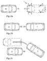
- Figures 2a-2c illustrate a risk situation.
- a vehicle 1 comprising a system according to the invention drives in a forward direction, as indicated by the arrow. It is further assumed that the vehicle 1 comprises an active safety system. suddenly another vehicle 11 driving in an opposite direction comes over on the same half of the road as the vehicle 1. There is therefore a risk for a frontal collision. However, the detection means 3 of the vehicle 1 detects the opposing vehicle 11.
- the activation means 7 activates the friction enhancing means 5.
- the active safety system makes the vehicle 1 brake, thereby decreasing its speed as seen in Figure 2b . Since the collision anyway cannot be avoided, the active safety system makes the vehicle 1 steer around the opposing vehicle 11, as in Figure 2c , thereby avoiding the frontal collision.
- the friction enhancing means 5 has made both the braking and the steering around more efficient by providing more friction between the tyres and the road, as compared to the case without any friction enhancing means 5.
- the vehicle 1 may instead be the driver of the vehicle 1 actively braking and steering around.
- Figures 3-6 illustrate a number of friction enhancing means. They may be used alone or in combination.
- a container 13 is filled with a liquid or granular substance 15, e.g. sand.
- a liquid or granular substance 15, e.g. sand When the friction enhancing means is activated, the container 13 opens and releases the substance 15. The release may be speeded up by having over-pressure in the container 13.
- the substance 15 lands on the ground 10 immediately in front of the tyre 9. As the vehicle moves forward, the tyre 9 will run over ground 10 at least partly covered by the substance 15. Thereby enhanced friction is achieved.
- the substance 15 may be applied to the tyre 9 instead.
- Figure 4 illustrates another setup, wherein the friction enhancing means 17 is located in the wheel house.
- a liquid or granular substance is applied on the tyre 9.
- a chemical 19 is sprayed on to the tyre 9.
- the chemical gives the tyre a tacky surface, thereby improving its friction to the ground 10.
- the chemical may be applied to the ground 10 instead.
- the container 17 is then suitably located like the container 13 of Figure 3 .
- Figures 5 and 6 illustrate friction enhancing means comprised in the tyre 9, here in the form of deployable spikes 21.
- the upper part of tyre 9 is seen in cross-sectional view.
- the spikes 21 are hidden in the tyre 9.
- the activation means 23 deploys the spikes 21.
- magnetic means 23 are used, which attract the spikes 21 upon activation and thereby pulls them out of the tyre 9.
- the activation means may also be located within the wheel. In that case the spikes 21 may be activated by a repulsive force.
Abstract
- detection means (3) for detection of the risk situation;
- friction enhancing means (5, 13, 17, 21) for increasing the friction between a tyre (9) of the vehicle (1) and the ground (10);
- activation means (7, 23) for activation of the friction enhancing means (5, 13, 17, 21) upon detection of the risk situation.
- detecting a risk situation;
- activating friction enhancing means (5, 13, 17, 21) upon detection of the risk situation.
Description
- The present invention relates to a system for operation of a vehicle in a risk situation.
- It is since long well-known to use friction-enhancing means to improve the friction between tyres and the ground. For example, during winter time in the Nordic countries, many vehicles use winter tyres with studs to improve the grip of the wheels. The wheels are then normally changed once in the autumn and once in the spring, and the studs are used for the whole winter no matter the road conditions, sometimes causing unnecessary wear of the roads.
- It is further also known to spread friction-enhancing substances, such as sand, on a road in order to improve the grip of the wheels. However, since it is impossible to know before-hand, where the grip is most needed, the sand is usually spread over a large portion of the road, which both takes time and causes costs.
- The object of the present invention is to overcome or ameliorate at least one of the disadvantages of the prior art, or to provide a useful alternative.
- It is desirable to provide a system being able to make the use of friction enhancing means more efficient.
- The object above may be achieved by the invention according to
claim 1. - In a first aspect of the present invention there is provided a system for operation of a vehicle in a risk situation, the system comprising
- detection means for detection of the risk situation;
- friction enhancing means for increasing the friction between a tyre of the vehicle and the ground;
- activation means for activation of the friction enhancing means upon detection of the risk situation.
- The operation of the vehicle includes braking or acceleration, as well as manoeuvring of the vehicle. The manoeuvring includes steering around a possible danger.
- By risk situation is meant a situation of potential danger or difficulty. The potential danger may be a collision with another vehicle or a moving or fixed object on or beside the road, e.g. a road sign. The danger may also be the risk of going off the road. The risk situation may be an emergency situation, but may also a potential emergency situation, i.e. an emergency situation that may be avoided, if the vehicle is operated appropriately.
- The word situation implies that the risk situation in many cases is an unplanned happening, not known before-hand and not planned for. Examples of risk situations are movements of other vehicles, cyclists, pedestrians or animals, or unforeseen road conditions such as an obstacle on the road. The risk situation normally lasts for a limited amount of time, purely as an example, a few seconds or even milliseconds.
- The aim of the system according to the invention is to reduce the risk that the potential danger will actually happen, e.g. the risk of a collision. If the danger is unavoidable, another aim of the invention is to reduce the negative consequences, e.g. to reduce possible personal injuries or damages to the vehicle. This is achieved since the system according to the invention facilitates the operation of the vehicle in the risk situation. The system may for example provide a more efficient braking, or a chance to steer around the danger, due to the increased friction. By steering around, a collision may be avoided. If colliding at a lower speed, achieved by the more efficient braking, there is less risk of injuring persons and the damages of the vehicle will be less and thereby the cost. If the risk is totally avoided, there may only be a cost for the friction enhancing means itself, e.g. to replace it. That cost is normally considerably lower as compared to for example the costs of a collision.
- Dependent on type of friction enhancing means, it may be re-usable or it may need replacement after use. Preferably, it should be possible to continue driving the vehicle in a normal way after having activated the friction enhancing means. The replacement may be performed by a workshop and/or by the vehicle user himself.
- Several detection means including radar, lidar, camera, IR-camera for detecting objects adjacent to the vehicle, primarily ahead of, are known, and will not be described in any detail in this document.
- The friction enhancing means influences the friction between a tyre and the ground. In most cases the ground is the road itself, whereupon the vehicle is driving, but the ground may also be ice, snow, mud or any other material on the road. The vehicle may also end up outside the road, e.g. on the verge or in the terrain, and in that case the ground may also be grass or gravel.
- The system according to the invention may form part of an active safety system of the vehicle. Such an active safety system may use sensors to detect upcoming threats and decide upon operations how to avoid the threats, e.g. by braking or steering around. The above-mentioned detection means could for example be an active safety sensor.
- Modern vehicles may be equipped with ESP, i.e. Electronic Stability Program. The ESP only intervenes when it detects loss of steering control, i.e. when the vehicle is not going where the driver is steering. This may happen, for example due to slipping or skidding, when for example steering around an obstacle in order to avoid a collision, on slippery roads or due to hydroplaning. The ESP can estimate the direction of the skid, and then apply the brakes to individual wheels asymmetrically in order to oppose the skid and bringing the vehicle back in line with the driver's commanded direction. The ESP thus interacts with the vehicle by means of the brakes. However, a system according to the invention can improve the function of the ESP, by providing an increased friction between the tyre and the road. A detector of the ESP system can be used as the above-mentioned detection means.
- The activation of the friction enhancing means by the activation means may occur automatically, i.e. without participation from the driver. Moreover, the operation in the risk situation may itself also be automatic, e.g. automatic braking of the vehicle. This may for example be the case, if the above system forms a part of an active safety system.
- On the other hand, it may also be possible for the driver to manually activate the friction enhancing means when desired, e.g. if the vehicle has got stuck in mud, in snow or on ice. The driver may in that case form the detection means himself. Automatic and manual activation may be combined. However, a preferred embodiment of the invention includes the automatic activation.
- The friction enhancing means may affect the friction between an individual tyre and the ground. It is often appropriate to affect both wheels of the same axle at the same time, or the tyres of all four wheels. Each wheel may have its friction enhancing means, or the same friction enhancing means may be used for more than one wheel. In a preferred embodiment, all four wheels have their corresponding friction enhancing means. Each wheel may have its own activation means, or a central activation means may be used for activating the friction enhancing means for more than one wheel.
- The friction enhancing means may increase the friction between a tyre of the vehicle and the ground chemically and/or mechanically. A chemical means can be used to change the surface properties of the ground and/or tyre, thereby increasing the friction. A mechanical means may be used to increase the mechanical friction, e.g. by making the surfaces rougher. Examples are given below.
- In an embodiment of the invention the friction enhancing means works together with the normal braking system of the vehicle. Consequently, no additional braking system intended for risk situations only is needed. Instead the friction enhancing means improves the function of the normal braking system by increasing the friction between the tyre and the ground. Thereby the risk of slipping, skidding or spinning is reduced.
- The increased friction may be achieved by the friction enhancing means interacting with the tyre and/or the ground in order to enhance the friction between the tyre of the vehicle and the ground. The friction enhancing means may for example affect the surface properties of the tyre and/or ground. If the ground is affected, it is normally most important to affect the region of the ground being just ahead of the tyre, i.e. the ground whereupon the tyre will run in the immediate future. The effect on the ground need not be restricted to this region; however, this is normally the region where a friction enhancement will have the greatest effect.
- The friction enhancing means may form an exchangeable part of the vehicle. The friction enhancing means can thereby be exchanged, if needed, when it has been used, and the vehicle will once again be prepared for a risk situation. It is further noticed, that the cost of a friction enhancing means is relatively low as compared to other vehicle parts. It is therefore considerably less expensive to replace a friction enhancing means as compared to repairing a vehicle, which has collided. As mentioned above, if the collision anyway is unavoidable, the system according to the invention reduces the damages and thereby the repair costs.
- The system according to the invention may be installed during manufacturing of a vehicle. Further, it may also be installed in an existing vehicle, for instance when it visits the workshop for service. Thereby it is possible to upgrade existing vehicles.
- The friction enhancing means may comprise a container filled with a liquid or granular substance, the substance being released from the container upon activation by the activation means. The liquid or granular substance may be adhesive, sticky or tacky. Examples of granular substances are sand, stone chips and road salt, possibly mixed with each other. Once the charge of the container has been released, it is recommendable to replace the container with a new one. The container is thus an example of an exchangeable part. The exchange may be performed by a workshop and/or by the vehicle user himself.
- The liquid or granular substance may be applied to the tyre, the wheel and/or the ground. It may be applied in various ways, for example by spraying, coating or physically pressing it against the tyre and/or the ground.
- The friction enhancing means may comprise a fabric or a net structure. The fabric or net structure may be activated by a gas generator in a similar way as an airbag.
- In an embodiment the friction enhancing means is comprised in the tyre and is adapted to be activated by the activation means. In that case, the friction enhancing means may comprise means increasing the mechanical friction, such as deployable spikes or studs. The spikes or studs are hidden in the tyre during normal running. Upon activation they may be deployed from the tyre, e.g. by pushing them out, pulling the out or rotating them from a tangential direction to a radial direction. The activation means may in that case be magnetic or electric means attracting or repulsing the spikes or studs. Repulsion may be used to push outwards, e.g. when the activation means are situated in the wheel. Attraction may be used when the activation means are situated at a least a part of the circumference of the tyre, e.g. in the wheel housing. It would also be possible to use pressurized gas to push the spikes outwards.
- The system according to the invention may further comprise means for estimating a risk level of the detected risk situation. For example, if a high risk for collision is estimated, it may be acceptable to use friction enhancing means, which are costly to replace and/ or partly destroys the vehicle, since these costs anyway are lower as compared to what the consequences would cost, if the collision would happen without using the friction enhancing means. On the other hand, if the estimated risk level is low, it would not make sense to use costly friction enhancing means. Further, it may not be worth using costly friction enhancing means, if it is estimated that the consequences of a collision would be small, e.g. due to low speed of the vehicle.
- In an embodiment comprising risk level estimation, the system comprises more than one friction enhancing means. Dependent on the estimated risk level of the detected risk situation, a certain friction enhancing means of the more than one friction enhancing means may be activated by the activation means. The system may in that case have two, three, four or more friction enhancing means. These may work on the same wheel/s and/or on different wheels of the vehicle. In a preferred embodiment comprising more than one friction enhancing means, the friction enhancing means are different and have different costs for use. An appropriate friction enhancing means is then selected based on the estimated risk level. Thereby it is possible to make a trade-off between costs for use of the friction enhancing means and costs for the consequences if not used.
- In another embodiment comprising risk level estimation, which may be combined with the previous embodiment, an activation level for the estimated risk level is selectable. The activation of the friction enhancing means by the activation means would then occur, if the estimated risk level of the detected risk situation is at least as high as the activation level. The activation level may be selected by the manufacturer, a workshop and/or the driver. It may be selected based on factors such as country, legislation, driver, state of the road, season etc.
- In a second aspect of the present invention there is provided a use of friction enhancing means during operation of a vehicle as a response to a detected risk situation.
- The different embodiments described above in relation to the first aspect of the invention are also relevant for the use described in the second aspect of the present invention.
- In a third aspect of the present invention there is provided a method comprising the steps of:
- detecting a risk situation;
- activating friction enhancing means upon detection of the risk situation.
- As described above the risk situation may be detected by above-mentioned detection means.
- In an embodiment, the friction enhancing means are selected based on the estimated risk level.
- The method may also comprise the step of selecting an activation level for the estimated risk level. The activation of the friction enhancing means would then occur, if the estimated risk level of the detected risk situation is at least as high as the activation level.
- The method may further comprise the step of
- applying a liquid or granular substance to the tyre, the wheel and/or the ground.
- The liquid or granular substance may be applied in various ways, for example by spraying, coating or physically pressing it against the tyre and/or the ground.
- In a fourth aspect of the present invention, there is provided a vehicle with the above-mentioned system for operation of a vehicle in a risk situation
- The present invention will hereinafter be further explained by means of non-limiting examples with reference to the appended figures wherein:
- Fig. 1
- is a schematic overview of a vehicle comprising a system according to the invention.
- Fig. 2a-c
- illustrates a risk situation.
- Fig. 3
- illustrates a friction enhancing means of a system according to the invention.
- Fig. 4
- illustrates another friction enhancing means.
- Fig. 5
- illustrates friction enhancing means of a system according to the invention in the form of deployable spikes.
- Fig. 6
- illustrates the deployable spikes of
Figure 5 after activation. - The invention will, in the following, be exemplified by embodiments. It should however be realized that the embodiments are included in order to explain principles of the invention and not to limit the scope of the invention, defined by the appended claims. Details from two or more of the embodiments may be combined with each other. The vehicles may for example be cars, buses, trucks or lorries.
-
Figure 1 schematically illustrates a schematic overview of avehicle 1 comprising a system according to the invention. The system comprises - detection means 3 for detection of the risk situation;
-
friction enhancing means 5 for increasing the friction between atyre 9 of the vehicle and theground 10; - activation means for activation 7 of the
friction enhancing means 5 upon detection of the risk situation. - The friction means 5 may be associated with the
tyres 9 of all four wheels, with a pair of wheels located at the same axle or with an individual wheel. - The detection means 3 for example may be radar, lidar, camera, IR-camera, either alone or in combinations.
Figure 1 illustrates detection means directed in the forward direction. There may also be other detection means directed sideways or rearwards (not illustrated).Figures 2a-2c illustrate a risk situation. Avehicle 1 comprising a system according to the invention drives in a forward direction, as indicated by the arrow. It is further assumed that thevehicle 1 comprises an active safety system. Suddenly anothervehicle 11 driving in an opposite direction comes over on the same half of the road as thevehicle 1. There is therefore a risk for a frontal collision. However, the detection means 3 of thevehicle 1 detects the opposingvehicle 11. The activation means 7 activates thefriction enhancing means 5. The active safety system makes thevehicle 1 brake, thereby decreasing its speed as seen inFigure 2b . Since the collision anyway cannot be avoided, the active safety system makes thevehicle 1 steer around the opposingvehicle 11, as inFigure 2c , thereby avoiding the frontal collision. In this example thefriction enhancing means 5 has made both the braking and the steering around more efficient by providing more friction between the tyres and the road, as compared to the case without anyfriction enhancing means 5. - In a similar way, assuming that the
vehicle 1 does not comprise an active safety system, it may instead be the driver of thevehicle 1 actively braking and steering around. -
Figures 3-6 illustrate a number of friction enhancing means. They may be used alone or in combination. - In
Figure 3 , acontainer 13 is filled with a liquid orgranular substance 15, e.g. sand. When the friction enhancing means is activated, thecontainer 13 opens and releases thesubstance 15. The release may be speeded up by having over-pressure in thecontainer 13. Thesubstance 15 lands on theground 10 immediately in front of thetyre 9. As the vehicle moves forward, thetyre 9 will run overground 10 at least partly covered by thesubstance 15. Thereby enhanced friction is achieved. As an alternative (not illustrated) thesubstance 15 may be applied to thetyre 9 instead. -
Figure 4 illustrates another setup, wherein thefriction enhancing means 17 is located in the wheel house. A liquid or granular substance is applied on thetyre 9. In this example a chemical 19 is sprayed on to thetyre 9. The chemical gives the tyre a tacky surface, thereby improving its friction to theground 10. As an alternative (not illustrated) the chemical may be applied to theground 10 instead. Thecontainer 17 is then suitably located like thecontainer 13 ofFigure 3 . -
Figures 5 and 6 illustrate friction enhancing means comprised in thetyre 9, here in the form ofdeployable spikes 21. The upper part oftyre 9 is seen in cross-sectional view. During normal running of the vehicle, thespikes 21 are hidden in thetyre 9. When a risk situation is detected, the activation means 23 deploys thespikes 21. In this example magnetic means 23 are used, which attract thespikes 21 upon activation and thereby pulls them out of thetyre 9. The activation means may also be located within the wheel. In that case thespikes 21 may be activated by a repulsive force. - Further modifications of the invention within the scope of the appended claims are feasible. As such, the present invention should not be considered as limited by the embodiments and figures described herein. Rather, the full scope of the invention should be determined by the appended claims, with reference to the description and drawings. The systems of the invention may be used in vehicles with or without active safety systems. However, it is noted, that the system of the invention may improve the function of the active safety system.
Claims (15)
- A system for operation of a vehicle (1) in a risk situation, said system comprising- detection means (3) for detection of said risk situation;- friction enhancing means (5, 13, 17, 21) for increasing the friction between a tyre (9) of said vehicle (1) and the ground (10);- activation means (7, 23) for activation of said friction enhancing means (5, 13, 17, 21) upon detection of said risk situation.
- The system according to claim 1, wherein said friction enhancing means (5, 13, 17, 21) chemically and/or mechanically increases said friction between a tyre (9) of said vehicle (1) and the ground (10).
- The system according to claim 1 or 2, wherein said friction enhancing means (5, 13, 17, 21) works together with the normal braking system of said vehicle (1).
- The system according to any one of the preceding claims, wherein said friction enhancing means (5, 13, 17, 21) interacts with the tyre (9) and/or the ground (10) in order to enhance the friction between the tyre (9) of said vehicle (1) and the ground (10).
- The system according to any one of the preceding claims, wherein said friction enhancing means (5, 13, 17, 21) forms an exchangeable part of said vehicle (1).
- The system according to any one of the preceding claims, wherein said friction enhancing means (5, 13, 17) comprises a container (13, 17) filled with a liquid (19) or granular substance (15), said substance being released from said container (13, 17) upon activation by said activation means (7).
- The system according to claim 6, wherein said liquid (19) or granular substance (15) is applied to the tyre (9) and/or the ground (10).
- The system according to any one of the preceding claims, wherein said friction enhancing means (5, 13, 17) comprises a fabric or a net structure.
- The system according to any one of the preceding claims, wherein said friction enhancing means (21) is comprised in the tyre (9) and is adapted to be activated by said activation means (23).
- The system according to claim 9, wherein said friction enhancing means comprises means increasing the mechanical friction, such as deployable spikes (21) or studs.
- The system according to any one of the preceding claims, said system further comprising means for estimating a risk level of said detected risk situation.
- The system according to claim 11, said system comprising more than one friction enhancing means (5, 13, 17, 21), wherein a certain friction enhancing means (5, 13, 17, 21) of said more than one friction enhancing means (5, 13, 17, 21) is activated by said activation means (7, 23), dependent on said estimated risk level of said detected risk situation.
- The system according to claim 11 or 12, wherein an activation level for said estimated risk level is selectable; the activation of said friction enhancing means (5, 13, 17, 21) by said activation means (7, 23) occurring, if said estimated risk level of said detected risk situation is at least as high as said activation level.
- A use of friction enhancing means (5, 13, 17, 21) during operation of a vehicle (1) as a response to a detected risk situation.
- A method comprising the steps of:- detecting a risk situation;- activating friction enhancing means (5, 13, 17, 21) upon detection of said risk situation.
Priority Applications (1)
| Application Number | Priority Date | Filing Date | Title |
|---|---|---|---|
| EP10160169.8A EP2377692B1 (en) | 2010-04-16 | 2010-04-16 | System for operation of a vehicle in a risk situation |
Applications Claiming Priority (1)
| Application Number | Priority Date | Filing Date | Title |
|---|---|---|---|
| EP10160169.8A EP2377692B1 (en) | 2010-04-16 | 2010-04-16 | System for operation of a vehicle in a risk situation |
Publications (2)
| Publication Number | Publication Date |
|---|---|
| EP2377692A1 true EP2377692A1 (en) | 2011-10-19 |
| EP2377692B1 EP2377692B1 (en) | 2013-07-24 |
Family
ID=42357352
Family Applications (1)
| Application Number | Title | Priority Date | Filing Date |
|---|---|---|---|
| EP10160169.8A Active EP2377692B1 (en) | 2010-04-16 | 2010-04-16 | System for operation of a vehicle in a risk situation |
Country Status (1)
| Country | Link |
|---|---|
| EP (1) | EP2377692B1 (en) |
Cited By (4)
| Publication number | Priority date | Publication date | Assignee | Title |
|---|---|---|---|---|
| WO2013179159A1 (en) * | 2012-06-01 | 2013-12-05 | Easy Rain I.S.R.L. | Anti-aquaplaning device for a vehicle |
| RU2507079C1 (en) * | 2012-10-22 | 2014-02-20 | Евгений Александрович Оленев | Method of articulated truck sideslip prevention |
| DE102015003640A1 (en) | 2014-04-08 | 2015-10-08 | Scania Cv Ab | Method and system for improving locomotion and motor vehicle |
| US10493966B2 (en) | 2017-08-02 | 2019-12-03 | Ford Global Technologies, Llc | Road surface traction system |
Citations (5)
| Publication number | Priority date | Publication date | Assignee | Title |
|---|---|---|---|---|
| US4826077A (en) * | 1987-12-07 | 1989-05-02 | Egy Michael J | Emergency traction device for vehicles |
| US20020079707A1 (en) * | 1999-01-22 | 2002-06-27 | James B. Skarie | Traction-enhancing system for use with motor vehicles |
| US20060060441A1 (en) * | 2002-10-08 | 2006-03-23 | Moriharu Sakai | Hybrid vehicle slip prevention apparatus |
| US20060213595A1 (en) * | 2005-03-28 | 2006-09-28 | Kevin Volt | Retractable Spike Pin Snow Tire |
| US20090165912A1 (en) * | 2007-12-31 | 2009-07-02 | Jean Joseph Victor Collette | Tire with retractable stud |
Family Cites Families (4)
| Publication number | Priority date | Publication date | Assignee | Title |
|---|---|---|---|---|
| DE3201602A1 (en) * | 1982-01-20 | 1983-07-28 | August 2000 Hamburg Ollech | Device for increasing the frictional resistance between the carriage way and the wheels of a vehicle |
| US6206299B1 (en) * | 1998-04-17 | 2001-03-27 | Commercial Vehicle Systems, Inc. | Traction enhancing deployment system |
| JP4290455B2 (en) * | 2003-03-28 | 2009-07-08 | 日産自動車株式会社 | Brake control device for vehicle |
| DE102006037658A1 (en) * | 2006-08-11 | 2008-02-14 | Bayerische Motoren Werke Ag | Unit increasing friction between vehicle tire and road, distributes adhesive- or solvent on tire, under control of measurement equipment on vehicle |
-
2010
- 2010-04-16 EP EP10160169.8A patent/EP2377692B1/en active Active
Patent Citations (5)
| Publication number | Priority date | Publication date | Assignee | Title |
|---|---|---|---|---|
| US4826077A (en) * | 1987-12-07 | 1989-05-02 | Egy Michael J | Emergency traction device for vehicles |
| US20020079707A1 (en) * | 1999-01-22 | 2002-06-27 | James B. Skarie | Traction-enhancing system for use with motor vehicles |
| US20060060441A1 (en) * | 2002-10-08 | 2006-03-23 | Moriharu Sakai | Hybrid vehicle slip prevention apparatus |
| US20060213595A1 (en) * | 2005-03-28 | 2006-09-28 | Kevin Volt | Retractable Spike Pin Snow Tire |
| US20090165912A1 (en) * | 2007-12-31 | 2009-07-02 | Jean Joseph Victor Collette | Tire with retractable stud |
Cited By (6)
| Publication number | Priority date | Publication date | Assignee | Title |
|---|---|---|---|---|
| WO2013179159A1 (en) * | 2012-06-01 | 2013-12-05 | Easy Rain I.S.R.L. | Anti-aquaplaning device for a vehicle |
| RU2624276C2 (en) * | 2012-06-01 | 2017-07-03 | Изи Рейн И.С.Р.Л. | Device against aquaplaning for vehicles |
| US9849724B2 (en) | 2012-06-01 | 2017-12-26 | Easy Rain I.S.R.L. | Anti-aquaplaning device for a vehicle |
| RU2507079C1 (en) * | 2012-10-22 | 2014-02-20 | Евгений Александрович Оленев | Method of articulated truck sideslip prevention |
| DE102015003640A1 (en) | 2014-04-08 | 2015-10-08 | Scania Cv Ab | Method and system for improving locomotion and motor vehicle |
| US10493966B2 (en) | 2017-08-02 | 2019-12-03 | Ford Global Technologies, Llc | Road surface traction system |
Also Published As
| Publication number | Publication date |
|---|---|
| EP2377692B1 (en) | 2013-07-24 |
Similar Documents
| Publication | Publication Date | Title |
|---|---|---|
| CN100393561C (en) | Hybrid vehicle slip prevention apparatus | |
| US9633565B2 (en) | Active safety system and method for operating the same | |
| US10268194B2 (en) | Method and system for assisted emergency braking | |
| EP2377692B1 (en) | System for operation of a vehicle in a risk situation | |
| US20070179697A1 (en) | Lane departure warning system and method | |
| US6802572B2 (en) | Brake control system | |
| CN105936260B (en) | Brake system and method for operating a brake system | |
| US6873898B1 (en) | Vehicle control system utilizing gps data | |
| WO2017076910A1 (en) | A control system and method for a vehicle comprising an autonomous emergency braking system | |
| WO2013029731A1 (en) | Method for a vehicle safety system and corresponding device | |
| JP2017507829A5 (en) | ||
| US20170340908A1 (en) | Apparatus, system and method for extinguishing a fire over the rear axle of a truck trailer | |
| US11814038B2 (en) | System for securing the parking of a motor vehicle | |
| US6447009B1 (en) | Emergency vehicle braking system employing adhesive substances | |
| US9416876B2 (en) | System and method for using all wheel drive coupling to enhance electronic parking brake function on a motor vehicle | |
| DE102018210172B4 (en) | Brake device for a vehicle, vehicle and method | |
| WO2007051268A3 (en) | Frontal safety light for motor vehicles | |
| DE102011104936A1 (en) | Device for increasing tire adhesion of road vehicle, has spraying device applying adhesion-strengthening agent before or under tire contact surface and/or on tread of tire of vehicle by determining slippage of tire in relation to track | |
| US20180211537A1 (en) | Method and device for braking a vehicle | |
| Rievaj et al. | Benefits of autonomously driven vehicles | |
| DE202004005845U1 (en) | Emergency braking system for a motor vehicle uses electronic control to force braking sled onto the carriageway using a gas pressure spring | |
| US20180134266A1 (en) | Hybrid non-abs/abs braking system | |
| KR20220117356A (en) | Road anti-skid system on black ice (snow, rain) | |
| DE10307079A1 (en) | Arrangement for braking vehicle, especially motor vehicle, has mechanically triggerable deceleration layers or mats anchored to vehicle that can be introduced between wheel contact surfaces and ground | |
| EP3504092B1 (en) | Air suspension evacuation for improved braking performance |
Legal Events
| Date | Code | Title | Description |
|---|---|---|---|
| AK | Designated contracting states |
Kind code of ref document: A1 Designated state(s): AT BE BG CH CY CZ DE DK EE ES FI FR GB GR HR HU IE IS IT LI LT LU LV MC MK MT NL NO PL PT RO SE SI SK SM TR |
|
| AX | Request for extension of the european patent |
Extension state: AL BA ME RS |
|
| PUAI | Public reference made under article 153(3) epc to a published international application that has entered the european phase |
Free format text: ORIGINAL CODE: 0009012 |
|
| 17P | Request for examination filed |
Effective date: 20120419 |
|
| 17Q | First examination report despatched |
Effective date: 20120625 |
|
| GRAP | Despatch of communication of intention to grant a patent |
Free format text: ORIGINAL CODE: EPIDOSNIGR1 |
|
| GRAP | Despatch of communication of intention to grant a patent |
Free format text: ORIGINAL CODE: EPIDOSNIGR1 |
|
| INTG | Intention to grant announced |
Effective date: 20130506 |
|
| GRAS | Grant fee paid |
Free format text: ORIGINAL CODE: EPIDOSNIGR3 |
|
| GRAA | (expected) grant |
Free format text: ORIGINAL CODE: 0009210 |
|
| AK | Designated contracting states |
Kind code of ref document: B1 Designated state(s): AT BE BG CH CY CZ DE DK EE ES FI FR GB GR HR HU IE IS IT LI LT LU LV MC MK MT NL NO PL PT RO SE SI SK SM TR |
|
| REG | Reference to a national code |
Ref country code: GB Ref legal event code: FG4D |
|
| REG | Reference to a national code |
Ref country code: CH Ref legal event code: EP |
|
| REG | Reference to a national code |
Ref country code: AT Ref legal event code: REF Ref document number: 623176 Country of ref document: AT Kind code of ref document: T Effective date: 20130815 |
|
| REG | Reference to a national code |
Ref country code: IE Ref legal event code: FG4D |
|
| REG | Reference to a national code |
Ref country code: DE Ref legal event code: R096 Ref document number: 602010008772 Country of ref document: DE Effective date: 20130919 |
|
| REG | Reference to a national code |
Ref country code: SE Ref legal event code: TRGR |
|
| REG | Reference to a national code |
Ref country code: AT Ref legal event code: MK05 Ref document number: 623176 Country of ref document: AT Kind code of ref document: T Effective date: 20130724 |
|
| REG | Reference to a national code |
Ref country code: NL Ref legal event code: VDEP Effective date: 20130724 |
|
| REG | Reference to a national code |
Ref country code: LT Ref legal event code: MG4D |
|
| PG25 | Lapsed in a contracting state [announced via postgrant information from national office to epo] |
Ref country code: LT Free format text: LAPSE BECAUSE OF FAILURE TO SUBMIT A TRANSLATION OF THE DESCRIPTION OR TO PAY THE FEE WITHIN THE PRESCRIBED TIME-LIMIT Effective date: 20130724 Ref country code: AT Free format text: LAPSE BECAUSE OF FAILURE TO SUBMIT A TRANSLATION OF THE DESCRIPTION OR TO PAY THE FEE WITHIN THE PRESCRIBED TIME-LIMIT Effective date: 20130724 Ref country code: IS Free format text: LAPSE BECAUSE OF FAILURE TO SUBMIT A TRANSLATION OF THE DESCRIPTION OR TO PAY THE FEE WITHIN THE PRESCRIBED TIME-LIMIT Effective date: 20131124 Ref country code: CY Free format text: LAPSE BECAUSE OF FAILURE TO SUBMIT A TRANSLATION OF THE DESCRIPTION OR TO PAY THE FEE WITHIN THE PRESCRIBED TIME-LIMIT Effective date: 20130724 Ref country code: NO Free format text: LAPSE BECAUSE OF FAILURE TO SUBMIT A TRANSLATION OF THE DESCRIPTION OR TO PAY THE FEE WITHIN THE PRESCRIBED TIME-LIMIT Effective date: 20131024 Ref country code: HR Free format text: LAPSE BECAUSE OF FAILURE TO SUBMIT A TRANSLATION OF THE DESCRIPTION OR TO PAY THE FEE WITHIN THE PRESCRIBED TIME-LIMIT Effective date: 20130724 Ref country code: PT Free format text: LAPSE BECAUSE OF FAILURE TO SUBMIT A TRANSLATION OF THE DESCRIPTION OR TO PAY THE FEE WITHIN THE PRESCRIBED TIME-LIMIT Effective date: 20131125 Ref country code: BE Free format text: LAPSE BECAUSE OF FAILURE TO SUBMIT A TRANSLATION OF THE DESCRIPTION OR TO PAY THE FEE WITHIN THE PRESCRIBED TIME-LIMIT Effective date: 20130724 |
|
| PG25 | Lapsed in a contracting state [announced via postgrant information from national office to epo] |
Ref country code: NL Free format text: LAPSE BECAUSE OF FAILURE TO SUBMIT A TRANSLATION OF THE DESCRIPTION OR TO PAY THE FEE WITHIN THE PRESCRIBED TIME-LIMIT Effective date: 20130724 Ref country code: FI Free format text: LAPSE BECAUSE OF FAILURE TO SUBMIT A TRANSLATION OF THE DESCRIPTION OR TO PAY THE FEE WITHIN THE PRESCRIBED TIME-LIMIT Effective date: 20130724 Ref country code: SI Free format text: LAPSE BECAUSE OF FAILURE TO SUBMIT A TRANSLATION OF THE DESCRIPTION OR TO PAY THE FEE WITHIN THE PRESCRIBED TIME-LIMIT Effective date: 20130724 Ref country code: PL Free format text: LAPSE BECAUSE OF FAILURE TO SUBMIT A TRANSLATION OF THE DESCRIPTION OR TO PAY THE FEE WITHIN THE PRESCRIBED TIME-LIMIT Effective date: 20130724 Ref country code: GR Free format text: LAPSE BECAUSE OF FAILURE TO SUBMIT A TRANSLATION OF THE DESCRIPTION OR TO PAY THE FEE WITHIN THE PRESCRIBED TIME-LIMIT Effective date: 20131025 Ref country code: LV Free format text: LAPSE BECAUSE OF FAILURE TO SUBMIT A TRANSLATION OF THE DESCRIPTION OR TO PAY THE FEE WITHIN THE PRESCRIBED TIME-LIMIT Effective date: 20130724 |
|
| PG25 | Lapsed in a contracting state [announced via postgrant information from national office to epo] |
Ref country code: SK Free format text: LAPSE BECAUSE OF FAILURE TO SUBMIT A TRANSLATION OF THE DESCRIPTION OR TO PAY THE FEE WITHIN THE PRESCRIBED TIME-LIMIT Effective date: 20130724 Ref country code: CZ Free format text: LAPSE BECAUSE OF FAILURE TO SUBMIT A TRANSLATION OF THE DESCRIPTION OR TO PAY THE FEE WITHIN THE PRESCRIBED TIME-LIMIT Effective date: 20130724 Ref country code: DK Free format text: LAPSE BECAUSE OF FAILURE TO SUBMIT A TRANSLATION OF THE DESCRIPTION OR TO PAY THE FEE WITHIN THE PRESCRIBED TIME-LIMIT Effective date: 20130724 Ref country code: EE Free format text: LAPSE BECAUSE OF FAILURE TO SUBMIT A TRANSLATION OF THE DESCRIPTION OR TO PAY THE FEE WITHIN THE PRESCRIBED TIME-LIMIT Effective date: 20130724 Ref country code: RO Free format text: LAPSE BECAUSE OF FAILURE TO SUBMIT A TRANSLATION OF THE DESCRIPTION OR TO PAY THE FEE WITHIN THE PRESCRIBED TIME-LIMIT Effective date: 20130724 |
|
| PG25 | Lapsed in a contracting state [announced via postgrant information from national office to epo] |
Ref country code: ES Free format text: LAPSE BECAUSE OF FAILURE TO SUBMIT A TRANSLATION OF THE DESCRIPTION OR TO PAY THE FEE WITHIN THE PRESCRIBED TIME-LIMIT Effective date: 20130724 Ref country code: IT Free format text: LAPSE BECAUSE OF FAILURE TO SUBMIT A TRANSLATION OF THE DESCRIPTION OR TO PAY THE FEE WITHIN THE PRESCRIBED TIME-LIMIT Effective date: 20130724 |
|
| PLBE | No opposition filed within time limit |
Free format text: ORIGINAL CODE: 0009261 |
|
| STAA | Information on the status of an ep patent application or granted ep patent |
Free format text: STATUS: NO OPPOSITION FILED WITHIN TIME LIMIT |
|
| 26N | No opposition filed |
Effective date: 20140425 |
|
| REG | Reference to a national code |
Ref country code: DE Ref legal event code: R097 Ref document number: 602010008772 Country of ref document: DE Effective date: 20140425 |
|
| PG25 | Lapsed in a contracting state [announced via postgrant information from national office to epo] |
Ref country code: MC Free format text: LAPSE BECAUSE OF FAILURE TO SUBMIT A TRANSLATION OF THE DESCRIPTION OR TO PAY THE FEE WITHIN THE PRESCRIBED TIME-LIMIT Effective date: 20130724 Ref country code: LU Free format text: LAPSE BECAUSE OF FAILURE TO SUBMIT A TRANSLATION OF THE DESCRIPTION OR TO PAY THE FEE WITHIN THE PRESCRIBED TIME-LIMIT Effective date: 20140416 |
|
| REG | Reference to a national code |
Ref country code: CH Ref legal event code: PL |
|
| REG | Reference to a national code |
Ref country code: FR Ref legal event code: ST Effective date: 20141231 |
|
| REG | Reference to a national code |
Ref country code: IE Ref legal event code: MM4A |
|
| PG25 | Lapsed in a contracting state [announced via postgrant information from national office to epo] |
Ref country code: CH Free format text: LAPSE BECAUSE OF NON-PAYMENT OF DUE FEES Effective date: 20140430 Ref country code: LI Free format text: LAPSE BECAUSE OF NON-PAYMENT OF DUE FEES Effective date: 20140430 |
|
| PG25 | Lapsed in a contracting state [announced via postgrant information from national office to epo] |
Ref country code: FR Free format text: LAPSE BECAUSE OF NON-PAYMENT OF DUE FEES Effective date: 20140430 |
|
| PG25 | Lapsed in a contracting state [announced via postgrant information from national office to epo] |
Ref country code: IE Free format text: LAPSE BECAUSE OF NON-PAYMENT OF DUE FEES Effective date: 20140416 |
|
| PG25 | Lapsed in a contracting state [announced via postgrant information from national office to epo] |
Ref country code: MT Free format text: LAPSE BECAUSE OF FAILURE TO SUBMIT A TRANSLATION OF THE DESCRIPTION OR TO PAY THE FEE WITHIN THE PRESCRIBED TIME-LIMIT Effective date: 20130724 |
|
| PG25 | Lapsed in a contracting state [announced via postgrant information from national office to epo] |
Ref country code: SM Free format text: LAPSE BECAUSE OF FAILURE TO SUBMIT A TRANSLATION OF THE DESCRIPTION OR TO PAY THE FEE WITHIN THE PRESCRIBED TIME-LIMIT Effective date: 20130724 |
|
| PG25 | Lapsed in a contracting state [announced via postgrant information from national office to epo] |
Ref country code: BG Free format text: LAPSE BECAUSE OF FAILURE TO SUBMIT A TRANSLATION OF THE DESCRIPTION OR TO PAY THE FEE WITHIN THE PRESCRIBED TIME-LIMIT Effective date: 20130724 |
|
| PG25 | Lapsed in a contracting state [announced via postgrant information from national office to epo] |
Ref country code: HU Free format text: LAPSE BECAUSE OF FAILURE TO SUBMIT A TRANSLATION OF THE DESCRIPTION OR TO PAY THE FEE WITHIN THE PRESCRIBED TIME-LIMIT; INVALID AB INITIO Effective date: 20100416 Ref country code: TR Free format text: LAPSE BECAUSE OF FAILURE TO SUBMIT A TRANSLATION OF THE DESCRIPTION OR TO PAY THE FEE WITHIN THE PRESCRIBED TIME-LIMIT Effective date: 20130724 |
|
| PG25 | Lapsed in a contracting state [announced via postgrant information from national office to epo] |
Ref country code: MK Free format text: LAPSE BECAUSE OF FAILURE TO SUBMIT A TRANSLATION OF THE DESCRIPTION OR TO PAY THE FEE WITHIN THE PRESCRIBED TIME-LIMIT Effective date: 20130724 |
|
| PGFP | Annual fee paid to national office [announced via postgrant information from national office to epo] |
Ref country code: GB Payment date: 20190408 Year of fee payment: 10 |
|
| GBPC | Gb: european patent ceased through non-payment of renewal fee |
Effective date: 20200416 |
|
| PG25 | Lapsed in a contracting state [announced via postgrant information from national office to epo] |
Ref country code: GB Free format text: LAPSE BECAUSE OF NON-PAYMENT OF DUE FEES Effective date: 20200416 |
|
| PGFP | Annual fee paid to national office [announced via postgrant information from national office to epo] |
Ref country code: SE Payment date: 20210329 Year of fee payment: 12 |
|
| REG | Reference to a national code |
Ref country code: SE Ref legal event code: EUG |
|
| PG25 | Lapsed in a contracting state [announced via postgrant information from national office to epo] |
Ref country code: SE Free format text: LAPSE BECAUSE OF NON-PAYMENT OF DUE FEES Effective date: 20220417 |
|
| PGFP | Annual fee paid to national office [announced via postgrant information from national office to epo] |
Ref country code: DE Payment date: 20230321 Year of fee payment: 14 |
|
| P01 | Opt-out of the competence of the unified patent court (upc) registered |
Effective date: 20231212 |