EP2384149B1 - Tissue anchors for purse-string closure of perforations - Google Patents
Tissue anchors for purse-string closure of perforations Download PDFInfo
- Publication number
- EP2384149B1 EP2384149B1 EP09764685.5A EP09764685A EP2384149B1 EP 2384149 B1 EP2384149 B1 EP 2384149B1 EP 09764685 A EP09764685 A EP 09764685A EP 2384149 B1 EP2384149 B1 EP 2384149B1
- Authority
- EP
- European Patent Office
- Prior art keywords
- crossbar
- strand
- suture
- tissue anchor
- loop
- Prior art date
- Legal status (The legal status is an assumption and is not a legal conclusion. Google has not performed a legal analysis and makes no representation as to the accuracy of the status listed.)
- Active
Links
- 239000002184 metal Substances 0.000 claims description 4
- 239000002783 friction material Substances 0.000 claims description 3
- 239000000463 material Substances 0.000 description 9
- 238000000034 method Methods 0.000 description 8
- 238000010276 construction Methods 0.000 description 5
- 229920003023 plastic Polymers 0.000 description 4
- 239000004033 plastic Substances 0.000 description 4
- 229920000954 Polyglycolide Polymers 0.000 description 3
- 238000012986 modification Methods 0.000 description 3
- 230000004048 modification Effects 0.000 description 3
- 229920000642 polymer Polymers 0.000 description 3
- 238000005299 abrasion Methods 0.000 description 2
- 239000000853 adhesive Substances 0.000 description 2
- 230000001070 adhesive effect Effects 0.000 description 2
- 210000001124 body fluid Anatomy 0.000 description 2
- 239000010839 body fluid Substances 0.000 description 2
- 239000013256 coordination polymer Substances 0.000 description 2
- 229920000747 poly(lactic acid) Polymers 0.000 description 2
- 239000004633 polyglycolic acid Substances 0.000 description 2
- 241000894006 Bacteria Species 0.000 description 1
- BVKZGUZCCUSVTD-UHFFFAOYSA-L Carbonate Chemical compound [O-]C([O-])=O BVKZGUZCCUSVTD-UHFFFAOYSA-L 0.000 description 1
- 229920002101 Chitin Polymers 0.000 description 1
- 229920002307 Dextran Polymers 0.000 description 1
- 102000009123 Fibrin Human genes 0.000 description 1
- 108010073385 Fibrin Proteins 0.000 description 1
- BWGVNKXGVNDBDI-UHFFFAOYSA-N Fibrin monomer Chemical compound CNC(=O)CNC(=O)CN BWGVNKXGVNDBDI-UHFFFAOYSA-N 0.000 description 1
- AEMRFAOFKBGASW-UHFFFAOYSA-N Glycolic acid Polymers OCC(O)=O AEMRFAOFKBGASW-UHFFFAOYSA-N 0.000 description 1
- 229920003171 Poly (ethylene oxide) Polymers 0.000 description 1
- 229920002732 Polyanhydride Polymers 0.000 description 1
- 229920000331 Polyhydroxybutyrate Polymers 0.000 description 1
- 229940061720 alpha hydroxy acid Drugs 0.000 description 1
- 150000001280 alpha hydroxy acids Chemical class 0.000 description 1
- 230000004888 barrier function Effects 0.000 description 1
- 150000001277 beta hydroxy acids Chemical class 0.000 description 1
- 230000015572 biosynthetic process Effects 0.000 description 1
- 239000005018 casein Substances 0.000 description 1
- BECPQYXYKAMYBN-UHFFFAOYSA-N casein, tech. Chemical compound NCCCCC(C(O)=O)N=C(O)C(CC(O)=O)N=C(O)C(CCC(O)=N)N=C(O)C(CC(C)C)N=C(O)C(CCC(O)=O)N=C(O)C(CC(O)=O)N=C(O)C(CCC(O)=O)N=C(O)C(C(C)O)N=C(O)C(CCC(O)=N)N=C(O)C(CCC(O)=N)N=C(O)C(CCC(O)=N)N=C(O)C(CCC(O)=O)N=C(O)C(CCC(O)=O)N=C(O)C(COP(O)(O)=O)N=C(O)C(CCC(O)=N)N=C(O)C(N)CC1=CC=CC=C1 BECPQYXYKAMYBN-UHFFFAOYSA-N 0.000 description 1
- 235000021240 caseins Nutrition 0.000 description 1
- 229920002678 cellulose Polymers 0.000 description 1
- 239000001913 cellulose Substances 0.000 description 1
- 238000000576 coating method Methods 0.000 description 1
- 230000006835 compression Effects 0.000 description 1
- 238000007906 compression Methods 0.000 description 1
- 229920001577 copolymer Polymers 0.000 description 1
- 230000002498 deadly effect Effects 0.000 description 1
- 229950003499 fibrin Drugs 0.000 description 1
- 239000012530 fluid Substances 0.000 description 1
- 210000001035 gastrointestinal tract Anatomy 0.000 description 1
- 150000004676 glycans Chemical class 0.000 description 1
- 229920001519 homopolymer Polymers 0.000 description 1
- 208000015181 infectious disease Diseases 0.000 description 1
- 239000000203 mixture Substances 0.000 description 1
- 102000035118 modified proteins Human genes 0.000 description 1
- 108091005573 modified proteins Proteins 0.000 description 1
- 238000010137 moulding (plastic) Methods 0.000 description 1
- 150000002905 orthoesters Chemical class 0.000 description 1
- 229920000729 poly(L-lysine) polymer Polymers 0.000 description 1
- 229920001308 poly(aminoacid) Polymers 0.000 description 1
- 239000005015 poly(hydroxybutyrate) Substances 0.000 description 1
- 229920000218 poly(hydroxyvalerate) Polymers 0.000 description 1
- 229920002627 poly(phosphazenes) Polymers 0.000 description 1
- 229920001610 polycaprolactone Polymers 0.000 description 1
- 239000004632 polycaprolactone Substances 0.000 description 1
- 239000000622 polydioxanone Substances 0.000 description 1
- 229920006149 polyester-amide block copolymer Polymers 0.000 description 1
- 229920002643 polyglutamic acid Polymers 0.000 description 1
- 239000004626 polylactic acid Substances 0.000 description 1
- 229920001282 polysaccharide Polymers 0.000 description 1
- 239000005017 polysaccharide Substances 0.000 description 1
- 238000005476 soldering Methods 0.000 description 1
- 239000007787 solid Substances 0.000 description 1
- 239000003356 suture material Substances 0.000 description 1
- 230000009278 visceral effect Effects 0.000 description 1
- 238000003466 welding Methods 0.000 description 1
Images

Classifications
-
- A—HUMAN NECESSITIES
- A61—MEDICAL OR VETERINARY SCIENCE; HYGIENE
- A61B—DIAGNOSIS; SURGERY; IDENTIFICATION
- A61B17/00—Surgical instruments, devices or methods, e.g. tourniquets
- A61B17/04—Surgical instruments, devices or methods, e.g. tourniquets for suturing wounds; Holders or packages for needles or suture materials
- A61B17/0401—Suture anchors, buttons or pledgets, i.e. means for attaching sutures to bone, cartilage or soft tissue; Instruments for applying or removing suture anchors
-
- A—HUMAN NECESSITIES
- A61—MEDICAL OR VETERINARY SCIENCE; HYGIENE
- A61B—DIAGNOSIS; SURGERY; IDENTIFICATION
- A61B17/00—Surgical instruments, devices or methods, e.g. tourniquets
- A61B17/04—Surgical instruments, devices or methods, e.g. tourniquets for suturing wounds; Holders or packages for needles or suture materials
- A61B17/0487—Suture clamps, clips or locks, e.g. for replacing suture knots; Instruments for applying or removing suture clamps, clips or locks
-
- A—HUMAN NECESSITIES
- A61—MEDICAL OR VETERINARY SCIENCE; HYGIENE
- A61B—DIAGNOSIS; SURGERY; IDENTIFICATION
- A61B17/00—Surgical instruments, devices or methods, e.g. tourniquets
- A61B2017/00004—(bio)absorbable, (bio)resorbable, resorptive
-
- A—HUMAN NECESSITIES
- A61—MEDICAL OR VETERINARY SCIENCE; HYGIENE
- A61B—DIAGNOSIS; SURGERY; IDENTIFICATION
- A61B17/00—Surgical instruments, devices or methods, e.g. tourniquets
- A61B17/04—Surgical instruments, devices or methods, e.g. tourniquets for suturing wounds; Holders or packages for needles or suture materials
- A61B17/0401—Suture anchors, buttons or pledgets, i.e. means for attaching sutures to bone, cartilage or soft tissue; Instruments for applying or removing suture anchors
- A61B2017/0414—Suture anchors, buttons or pledgets, i.e. means for attaching sutures to bone, cartilage or soft tissue; Instruments for applying or removing suture anchors having a suture-receiving opening, e.g. lateral opening
-
- A—HUMAN NECESSITIES
- A61—MEDICAL OR VETERINARY SCIENCE; HYGIENE
- A61B—DIAGNOSIS; SURGERY; IDENTIFICATION
- A61B17/00—Surgical instruments, devices or methods, e.g. tourniquets
- A61B17/04—Surgical instruments, devices or methods, e.g. tourniquets for suturing wounds; Holders or packages for needles or suture materials
- A61B17/0401—Suture anchors, buttons or pledgets, i.e. means for attaching sutures to bone, cartilage or soft tissue; Instruments for applying or removing suture anchors
- A61B2017/0417—T-fasteners
-
- A—HUMAN NECESSITIES
- A61—MEDICAL OR VETERINARY SCIENCE; HYGIENE
- A61B—DIAGNOSIS; SURGERY; IDENTIFICATION
- A61B17/00—Surgical instruments, devices or methods, e.g. tourniquets
- A61B17/04—Surgical instruments, devices or methods, e.g. tourniquets for suturing wounds; Holders or packages for needles or suture materials
- A61B17/0401—Suture anchors, buttons or pledgets, i.e. means for attaching sutures to bone, cartilage or soft tissue; Instruments for applying or removing suture anchors
- A61B2017/0446—Means for attaching and blocking the suture in the suture anchor
- A61B2017/0458—Longitudinal through hole, e.g. suture blocked by a distal suture knot
-
- A—HUMAN NECESSITIES
- A61—MEDICAL OR VETERINARY SCIENCE; HYGIENE
- A61B—DIAGNOSIS; SURGERY; IDENTIFICATION
- A61B17/00—Surgical instruments, devices or methods, e.g. tourniquets
- A61B17/11—Surgical instruments, devices or methods, e.g. tourniquets for performing anastomosis; Buttons for anastomosis
- A61B2017/1142—Purse-string sutures
-
- Y—GENERAL TAGGING OF NEW TECHNOLOGICAL DEVELOPMENTS; GENERAL TAGGING OF CROSS-SECTIONAL TECHNOLOGIES SPANNING OVER SEVERAL SECTIONS OF THE IPC; TECHNICAL SUBJECTS COVERED BY FORMER USPC CROSS-REFERENCE ART COLLECTIONS [XRACs] AND DIGESTS
- Y10—TECHNICAL SUBJECTS COVERED BY FORMER USPC
- Y10T—TECHNICAL SUBJECTS COVERED BY FORMER US CLASSIFICATION
- Y10T24/00—Buckles, buttons, clasps, etc.
- Y10T24/39—Cord and rope holders
- Y10T24/3913—Knot engaging
-
- Y—GENERAL TAGGING OF NEW TECHNOLOGICAL DEVELOPMENTS; GENERAL TAGGING OF CROSS-SECTIONAL TECHNOLOGIES SPANNING OVER SEVERAL SECTIONS OF THE IPC; TECHNICAL SUBJECTS COVERED BY FORMER USPC CROSS-REFERENCE ART COLLECTIONS [XRACs] AND DIGESTS
- Y10—TECHNICAL SUBJECTS COVERED BY FORMER USPC
- Y10T—TECHNICAL SUBJECTS COVERED BY FORMER US CLASSIFICATION
- Y10T24/00—Buckles, buttons, clasps, etc.
- Y10T24/39—Cord and rope holders
- Y10T24/3916—One-piece
Definitions
- the present invention relates generally to tissue anchors for connecting a suture to tissue, such are for using tissue anchors and suture to close perforations in tissue.
- Perforations in bodily walls may be naturally occurring, or formed intentionally or unintentionally.
- numerous medical devices and methods have been developed employing sutures, adhesives, clips, staples and the like.
- tissue anchors T-anchors
- An exemplary tissue anchor is disclosed in U.S. Pat. No. 5,123,914 .
- Such tissue anchors have been very successful in medical procedures requiring tissue wall mobilization or wall apposition.
- US Patent Application Pub. No. US 2004/0243179 discloses features falling under the preamble of claim 1.
- Tissue anchors have also been successfully used in closing perforations, but are not without their drawbacks. For example, when a series of anchors are placed around a perforation, all of the individual sutures connected to the anchors must be collected and connected together. It can often be difficult to properly tension each of the individual sutures to ensure proper approximation of the tissue around the perforation and complete closure thereof. This is especially critical within the gastrointestinal tract, where the travel of bacteria laden fluids outside of the tract may cause unwanted and sometimes deadly infection.
- a tissue anchor for connecting a suture to tissue constructed in accordance with the teachings of the present invention, generally comprises a crossbar and a strand.
- the crossbar has first and second opposing ends and defines a longitudinal axis.
- the crossbar is defined by a tubular wall having an aperture between the first and second ends.
- the strand has first and second opposing ends connected to the first and second opposing ends of the crossbar, respectively.
- the strand makes a revolution to define a loop.
- the strand and its loop project through the aperture and away from the longitudinal axis.
- the loop is sized to slidably receive the suture therethrough.
- the strand has a diameter less than about 50% of a diameter of the crossbar.
- the strand preferably has a diameter in the range of about 0.2 mm to about 0.35 mm, while the crossbar has a diameter in the range of about 0.5 mm to about 1.1 mm.
- the loop has an apex located about 0.35 mm or greater away from the crossbar.
- the loop defines a cross-point where the ends of the strand cross each other, and the cross-point is preferably positioned radially outside the outer surface of the crossbar.
- the strand is flexible, and the aperture is sized to permit the loop to travel longitudinally along the strand.
- the aperture preferably extends a longitudinal distance in the range of about 0.4 mm to about 3.0 mm, while the crossbar typically has a length in the range of about 3.0 mm to about 10.0 mm.
- the strand may be a metal wire, and is preferably coated with a low-friction material.
- tissue anchor for connecting a suture to tissue, constructed in accordance with the teachings of the present disclosure, generally comprises a crossbar and a strand.
- the crossbar has first and second opposing ends and defines a longitudinal axis.
- the cross bar is defined by a tubular wall having first and second apertures between the first and second ends, the first and second apertures being longitudinally spaced apart.
- a flexible suture has first and second opposing ends connected to the first and second opposing ends of the crossbar, respectively. The suture extends through the first and second apertures and projects away from the crossbar between the first and second apertures to define a loop between the suture and the crossbar.
- a tissue anchor for connecting a suture to tissue generally comprises a crossbar and a flange.
- the crossbar has first and second opposing ends and defines a longitudinal axis.
- the flange is connected to the crossbar between the first and second ends and extends away from the longitudinal axis.
- the flange has a thickness less than a diameter of the crossbar.
- the flange defines a hole sized to receive the suture therein.
- an outer end surface of the flange follows a curved shape.
- the crossbar and flange are unitarily and integrally formed.
- the crossbar and flange are optionally molded from a resorbable material.
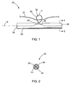
- FIGS. 1-2 depict a tissue anchor 20 constructed in accordance with the teachings of the present invention.
- the anchor 20 is utilized to connect a suture 22 to tissue, such as for closing a perforation 10 in a bodily wall 12 (see, e.g., FIGS. 6 to 9 ) or for use in other procedures.
- the anchor 20 generally includes a crossbar 24 having opposing ends 26 and 28 and defining a longitudinal axis 14.
- the crossbar 24 is preferably elongated, but may take any form suitable for connecting the suture 22 to the bodily wall 12.
- a strand 30 is connected to the crossbar 24 and is configured to form a loop 32. As best seen in FIG.
- the crossbar 24 is constructed of a cannula having a tubular wall 34 defining a lumen 36.
- An elongated aperture 38 is formed in the tubular wall 34, and the strand 30 passes through the aperture 38.
- the ends of strand 30 are secured within the lumen 36 of the cannula by welds 44. It will be recognized by those skilled in the art that the strand 30 may be secured to the crossbar 24 using any now known or hereinafter developed attachment means, including mechanical fasteners, adhesives or various welding or soldering techniques.
- the strand 30 may have sufficient rigidity such that its ends do not need to be directly attached to the crossbar, as the formation of loop 32 projecting through the aperture 38 can be enough to retain the strand 30 within the crossbar 24, and/or the ends of the strand 30 may simply be bent or otherwise deformed to keep them within the crossbar 24 and prevent them from passing through the aperture 38.
- the strand 30 is preferably formed from a metal wire, including single filament and multi-filament wires, and wound and braided wires, although the strand 30 can have other constructions such as suture material, plastic strings, rope and the like.
- the strand 30 is structured to include a revolution thereby defining a loop 32 through which the suture 22 passes.
- the loop 32 is positioned longitudinally in-line with the elongated aperture 38 so that it projects through the aperture 38 and away from the longitudinal axis 14. Accordingly, it will be seen that the strand 30 and its loop 32 are flexible and may adjust its shape and orientation based on how the suture 22 is being tensioned.
- the size of the elongated aperture 38 and the flexibility of the strand 30 allow the loop 32 to travel longitudinally along the length of the strand 30.
- the loop 32 defines an apex A which is preferably located about 0.35 mm or greater away from the crossbar 24.
- the loop 32 also defines a cross-point CP where the ends of the strand 30 cross each other.
- the cross-point CP is preferably positioned radially outside the outer surface of the crossbar 24 including radially outside the side walls of the aperture 38, but also preferably as close to the crossbar 24 as possible.
- the aperture 38 preferably extends a longitudinal distance in a range of about 0.4 mm to about 3.0 mm, while the crossbar 24 typically has a length in the range of about 3.0 mm to about 10.0 mm.
- the strand preferably has a diameter less than about 50% of a diameter of the crossbar 24, and most preferably less than about 35%.
- the strand 30 preferably has a diameter in the range of about 0.20 mm to about 0.35 mm, and most preferably about 0.254 mm.
- the crossbar 24 preferably has a diameter in the range of about 0.5 mm to about 1.0 mm, and most preferably about 0.8 mm.
- the strand 30 may be coated with a low-friction material such as known plastic or hydrophilic coatings.
- tissue anchor 24 and its loop 32 allows the suture 22 to be tensioned and slid through the loop 32 relative to the crossbar 24 while preventing the suture 22 from engaging the crossbar 24 or the edges defined by the elongated aperture 38. That is, no matter which direction the ends of the suture 22 are pulled or slid relative to the crossbar 24, the wire 30 and its loop 32 will serve as a barrier between the suture 22 and the canula 24 to prevent any undesired abrasion therebetween.
- the strand 30 has a length and the location of the apex A of the loop 32 are such that the loop 32 is sized to project through the tissue in which it is embedded (e.g. it projects from the proximal side of the tissue), allowing reliable tensioning of the suture 22 and preventing abrasion of the tissue.
- the anchor 120 generally includes a crossbar 124 having opposing ends 126 and 128.
- a strand 130 is connected to the crossbar 124, and in this embodiment, the strand 130 is formed of a flexible suture.
- the crossbar 24 defines first and second apertures 138, 140 which are longitudinally spaced apart. Moving from left to right in FIG.
- the strand 130 is attached to the crossbar 124 and passes through the interior of the crossbar 124 and exits radially from the first aperture 138, then extends along the outer periphery of the crossbar 124, and passes back through the second aperture 140 into the interior of the crossbar 124, where it is fixed to the second end 128 thereof.
- the flexible suture 130 and the crossbar 124 define a loop 132 therebetween which is sized to slidably receive the tying suture 22.
- the suture 130 has a length, preferably about 10 mm to about 30 mm, such that the distance the suture 130 projects away from the crossbar 124 is variable.
- the suture 130 when pulled taut, defines an apex that is positioned away from an outer surface of the crossbar about 5 mm.
- the suture 130 has a length 18 mm, whereas the crossbar 124 has a length of about 8 mm.
- the suture 130 may be of a single filament or multi-filament constructions. Through this construction of the suture 130 to form the loop 132, while friction between the anchor 120 and the tying suture 22 is reduced. The loop 132 and with the extra length of the suture 130, the crossbar 124 may be embedded deeper into the tissue.
- the anchor 220 generally includes a crossbar 224 having opposing ends 226 and 228.
- the crossbar 224 is preferably formed of a solid cylinder, and may be a metal bar, plastic molded piece, or any stock materials.
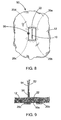
- the tissue anchor 220 also includes a flange 240 connected to the crossbar 224 and projecting radially away therefrom.
- the flange 240 preferably has a thickness (best seen in the side view of FIG. 5 ) that is less than 50% of the diameter of the crossbar 224.
- the flange 240 defines a hole 242 sized to slidably receive the tying suture 22 therein.
- the crossbar 224 and flange 240 are unitarily and integrally formed, such as in a plastic molding process. Accordingly, the entire tissue anchor 220 may be formed of a single plastic material, and most preferably a resorbable material. This construction of the tissue anchor 220 allows it to be placed in locations where, once the anchor was freed, it would likely not naturally pass through the body. Accordingly, no matter the location the tissue anchors 220, they are still allowed to naturally exit the body.
- resorbable refers to the ability of a material to be absorbed into a tissue and/or body fluid upon contact with the tissue and/or body fluid.
- a number of resorbable materials are known in the art, and any suitable resorbable material can be used. Examples of suitable types of resorbable materials include resorbable homopolymers, copolymers, or blends of resorbable polymers.
- suitable resorbable materials include poly-alpha hydroxy acids such as polylactic acid, polylactide, polyglycolic acid (PGA), or polyglycolide; trimethlyene carbonate; polycaprolactone; poly-beta hydroxy acids such as polyhydroxybutyrate or polyhydroxyvalerate; or other polymers such as polyphosphazines, polyorgano- phosphazines, polyanhydrides, polyesteramides, poly- orthoesters, polyethylene oxide, polyester-ethers (e.g., poly- dioxanone) or polyamino acids (e.g., poly-L-glutamic acid or poly-L-lysine).
- modified polysaccharides such as cellulose, chitin, and dextran
- modified proteins such as fibrin and casein.
- the tissue anchors 20 are preferably deployed as a set of anchors 20a, 20b, 20c, 20d linked together by a single suture 22, all of which collectively forms a medical device 50 for closing the perforation 10 in the bodily wall 12.
- the suture 22 is slidably connected to each of the tissue anchors 20a, 20b, 20c, and 20d, leaving two free ends 52, 54 of the suture 22 which may be independently tensioned to close the perforation 10. As best seen in FIG.
- the tissue anchors (20b and 20c depicted) are positioned on a distal side of the bodily wall 12, while the majority of suture 22 is positioned on a proximal side of the bodily wall 12, including the suture ends 52, 54. Accordingly, it will be recognized that the medical device 50 operates in a purse-string fashion to close the perforation 10 in the bodily wall, as will be described in more detail below.
- a method of closing the perforation 10, in accordance with the teachings of the present disclosure, includes passing each tissue anchor 20a, 20b, 20c, and 20d through the bodily wall 12 adjacent the periphery of the perforation 10, as shown in FIG. 6 .
- the anchors are sequentially positioned around the perforation 10 in a semi-annular or annular shape as shown.
- the ends 52, 54 of the suture are then tensioned to reduce the distance between the tissue anchors 20a, 20b, 20c, 20d and compress the bodily wall 12 around the perforation 10, as depicted in FIGS. 8 and 9 .
- FIG. 8 and 9 As best seen in FIG.
- the ends 52, 54 of the suture 22 are secured to maintain the compression of the bodily wall 10, such as through the use of a suture lock 56.
- exemplary suture locks are disclosed in copending U.S. Patent Application Nos. 12/125,525 and 12/191,001 . It will be recognized that any now known or future developed method for securing the ends 52, 54 of the suture 22 may be employed, such as knotting, tying, clamps, rivets and the like.
Description
- The present invention relates generally to tissue anchors for connecting a suture to tissue, such are for using tissue anchors and suture to close perforations in tissue.
- Perforations in bodily walls may be naturally occurring, or formed intentionally or unintentionally. In order to permanently close these perforations and allow the tissue to properly heal, numerous medical devices and methods have been developed employing sutures, adhesives, clips, staples and the like. One class of such devices is commonly referred to as tissue anchors (T-anchors) or visceral anchors. An exemplary tissue anchor is disclosed in
U.S. Pat. No. 5,123,914 . Such tissue anchors have been very successful in medical procedures requiring tissue wall mobilization or wall apposition. US Patent Application Pub. No.US 2004/0243179 discloses features falling under the preamble of claim 1. - Tissue anchors have also been successfully used in closing perforations, but are not without their drawbacks. For example, when a series of anchors are placed around a perforation, all of the individual sutures connected to the anchors must be collected and connected together. It can often be difficult to properly tension each of the individual sutures to ensure proper approximation of the tissue around the perforation and complete closure thereof. This is especially critical within the gastrointestinal tract, where the travel of bacteria laden fluids outside of the tract may cause unwanted and sometimes deadly infection.
- The present invention is defined in claim 1 and provides medical devices for attaching suture to tissue and that provides reliable and complete closure of perforations and increases the versatility of the device for various other procedures. A tissue anchor for connecting a suture to tissue, constructed in accordance with the teachings of the present invention, generally comprises a crossbar and a strand. The crossbar has first and second opposing ends and defines a longitudinal axis. The crossbar is defined by a tubular wall having an aperture between the first and second ends. The strand has first and second opposing ends connected to the first and second opposing ends of the crossbar, respectively. The strand makes a revolution to define a loop. The strand and its loop project through the aperture and away from the longitudinal axis. The loop is sized to slidably receive the suture therethrough.
- According to more detailed aspects of this tissue anchor, the strand has a diameter less than about 50% of a diameter of the crossbar. The strand preferably has a diameter in the range of about 0.2 mm to about 0.35 mm, while the crossbar has a diameter in the range of about 0.5 mm to about 1.1 mm. The loop has an apex located about 0.35 mm or greater away from the crossbar. The loop defines a cross-point where the ends of the strand cross each other, and the cross-point is preferably positioned radially outside the outer surface of the crossbar. The strand is flexible, and the aperture is sized to permit the loop to travel longitudinally along the strand. The aperture preferably extends a longitudinal distance in the range of about 0.4 mm to about 3.0 mm, while the crossbar typically has a length in the range of about 3.0 mm to about 10.0 mm. The strand may be a metal wire, and is preferably coated with a low-friction material.
- Another example of a tissue anchor for connecting a suture to tissue, constructed in accordance with the teachings of the present disclosure, generally comprises a crossbar and a strand. The crossbar has first and second opposing ends and defines a longitudinal axis. The cross bar is defined by a tubular wall having first and second apertures between the first and second ends, the first and second apertures being longitudinally spaced apart. A flexible suture has first and second opposing ends connected to the first and second opposing ends of the crossbar, respectively. The suture extends through the first and second apertures and projects away from the crossbar between the first and second apertures to define a loop between the suture and the crossbar.
- Yet another example of a tissue anchor for connecting a suture to tissue, constructed in accordance with the teachings of the present disclosure, generally comprises a crossbar and a flange. The crossbar has first and second opposing ends and defines a longitudinal axis. The flange is connected to the crossbar between the first and second ends and extends away from the longitudinal axis. The flange has a thickness less than a diameter of the crossbar. The flange defines a hole sized to receive the suture therein. According to more detailed aspects of this embodiment of the tissue anchor, an outer end surface of the flange follows a curved shape. Preferably, the crossbar and flange are unitarily and integrally formed. The crossbar and flange are optionally molded from a resorbable material.
- The accompanying drawings incorporated in and forming a part of the specification illustrate several aspects of the present invention, and together with the description serve to explain the principles of the invention. In the drawings:
-
FIG. 1 is a front view of a tissue anchor constructed in accordance with the teachings of the present invention; -
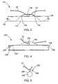
FIG. 2 is a cross-sectional view taken about the line 2-2 inFIG. 1 ; -
FIG. 3 is a front view of another example of a tissue anchor constructed in accordance with the teachings of the present disclosure; -
FIG. 4 is a front view of yet another example of a tissue anchor constructed in accordance with the teachings of the present disclosure; -
FIG. 5 is an end view taken of the tissue anchor depicted inFIG. 4 ; -
FIG. 6 is a plan view schematically depicting a medical device constructed in accordance with the teachings of the present disclosure; -
FIG. 7 is a cross-sectional view of the medical device depicted inFIG. 6 ; -
FIG. 8 is a schematic view of the medical device similar toFIG. 6 but showing the medical device closing a perforation; and -
FIG. 9 is a cross-sectional view of the medical device as depicted inFIG. 8 . - Turning now to the figures,
FIGS. 1-2 depict atissue anchor 20 constructed in accordance with the teachings of the present invention. Theanchor 20 is utilized to connect asuture 22 to tissue, such as for closing aperforation 10 in a bodily wall 12 (see, e.g.,FIGS. 6 to 9 ) or for use in other procedures. Theanchor 20 generally includes acrossbar 24 havingopposing ends longitudinal axis 14. Thecrossbar 24 is preferably elongated, but may take any form suitable for connecting thesuture 22 to thebodily wall 12. Astrand 30 is connected to thecrossbar 24 and is configured to form aloop 32. As best seen inFIG. 2 , thecrossbar 24 is constructed of a cannula having atubular wall 34 defining alumen 36. Anelongated aperture 38 is formed in thetubular wall 34, and thestrand 30 passes through theaperture 38. The ends ofstrand 30 are secured within thelumen 36 of the cannula by welds 44. It will be recognized by those skilled in the art that thestrand 30 may be secured to thecrossbar 24 using any now known or hereinafter developed attachment means, including mechanical fasteners, adhesives or various welding or soldering techniques. Similarly, thestrand 30 may have sufficient rigidity such that its ends do not need to be directly attached to the crossbar, as the formation ofloop 32 projecting through theaperture 38 can be enough to retain thestrand 30 within thecrossbar 24, and/or the ends of thestrand 30 may simply be bent or otherwise deformed to keep them within thecrossbar 24 and prevent them from passing through theaperture 38. - The
strand 30 is preferably formed from a metal wire, including single filament and multi-filament wires, and wound and braided wires, although thestrand 30 can have other constructions such as suture material, plastic strings, rope and the like. As best seen inFIG. 1 , thestrand 30 is structured to include a revolution thereby defining aloop 32 through which thesuture 22 passes. Theloop 32 is positioned longitudinally in-line with theelongated aperture 38 so that it projects through theaperture 38 and away from thelongitudinal axis 14. Accordingly, it will be seen that thestrand 30 and itsloop 32 are flexible and may adjust its shape and orientation based on how thesuture 22 is being tensioned. The size of theelongated aperture 38 and the flexibility of thestrand 30 allow theloop 32 to travel longitudinally along the length of thestrand 30. Theloop 32 defines an apex A which is preferably located about 0.35 mm or greater away from thecrossbar 24. Theloop 32 also defines a cross-point CP where the ends of thestrand 30 cross each other. The cross-point CP is preferably positioned radially outside the outer surface of thecrossbar 24 including radially outside the side walls of theaperture 38, but also preferably as close to thecrossbar 24 as possible. Theaperture 38 preferably extends a longitudinal distance in a range of about 0.4 mm to about 3.0 mm, while thecrossbar 24 typically has a length in the range of about 3.0 mm to about 10.0 mm. The strand preferably has a diameter less than about 50% of a diameter of thecrossbar 24, and most preferably less than about 35%. Thestrand 30 preferably has a diameter in the range of about 0.20 mm to about 0.35 mm, and most preferably about 0.254 mm. Thecrossbar 24 preferably has a diameter in the range of about 0.5 mm to about 1.0 mm, and most preferably about 0.8 mm. Thestrand 30 may be coated with a low-friction material such as known plastic or hydrophilic coatings. - This construction of the
tissue anchor 24 and itsloop 32 allows thesuture 22 to be tensioned and slid through theloop 32 relative to thecrossbar 24 while preventing thesuture 22 from engaging thecrossbar 24 or the edges defined by theelongated aperture 38. That is, no matter which direction the ends of thesuture 22 are pulled or slid relative to thecrossbar 24, thewire 30 and itsloop 32 will serve as a barrier between thesuture 22 and thecanula 24 to prevent any undesired abrasion therebetween. Generally, thestrand 30 has a length and the location of the apex A of theloop 32 are such that theloop 32 is sized to project through the tissue in which it is embedded (e.g. it projects from the proximal side of the tissue), allowing reliable tensioning of thesuture 22 and preventing abrasion of the tissue. - Turning now to
FIG. 3 , another example of atissue anchor 120 is depicted in accordance with the teachings of the present disclosure. As in the prior embodiment, theanchor 120 generally includes acrossbar 124 having opposing ends 126 and 128. Astrand 130 is connected to thecrossbar 124, and in this embodiment, thestrand 130 is formed of a flexible suture. Thecrossbar 24 defines first andsecond apertures FIG. 3 , thestrand 130 is attached to thecrossbar 124 and passes through the interior of thecrossbar 124 and exits radially from thefirst aperture 138, then extends along the outer periphery of thecrossbar 124, and passes back through thesecond aperture 140 into the interior of thecrossbar 124, where it is fixed to thesecond end 128 thereof. Accordingly, theflexible suture 130 and thecrossbar 124 define aloop 132 therebetween which is sized to slidably receive the tyingsuture 22. Thesuture 130 has a length, preferably about 10 mm to about 30 mm, such that the distance thesuture 130 projects away from thecrossbar 124 is variable. Thesuture 130, when pulled taut, defines an apex that is positioned away from an outer surface of the crossbar about 5 mm. Preferably thesuture 130 has a length 18 mm, whereas thecrossbar 124 has a length of about 8 mm. Thesuture 130 may be of a single filament or multi-filament constructions. Through this construction of thesuture 130 to form theloop 132, while friction between theanchor 120 and the tyingsuture 22 is reduced. Theloop 132 and with the extra length of thesuture 130, thecrossbar 124 may be embedded deeper into the tissue. - Turning now to
FIGS. 4 and 5 , in yet another example of atissue anchor 220 has been depicted in accordance with the teachings of the present disclosure. As with the prior examples theanchor 220 generally includes acrossbar 224 having opposing ends 226 and 228. In this example thecrossbar 224 is preferably formed of a solid cylinder, and may be a metal bar, plastic molded piece, or any stock materials. Thetissue anchor 220 also includes aflange 240 connected to thecrossbar 224 and projecting radially away therefrom. Theflange 240 preferably has a thickness (best seen in the side view ofFIG. 5 ) that is less than 50% of the diameter of thecrossbar 224. Theflange 240 defines ahole 242 sized to slidably receive the tyingsuture 22 therein. Preferably, thecrossbar 224 andflange 240 are unitarily and integrally formed, such as in a plastic molding process. Accordingly, theentire tissue anchor 220 may be formed of a single plastic material, and most preferably a resorbable material. This construction of thetissue anchor 220 allows it to be placed in locations where, once the anchor was freed, it would likely not naturally pass through the body. Accordingly, no matter the location the tissue anchors 220, they are still allowed to naturally exit the body. - As used herein, the term "resorbable" refers to the ability of a material to be absorbed into a tissue and/or body fluid upon contact with the tissue and/or body fluid. A number of resorbable materials are known in the art, and any suitable resorbable material can be used. Examples of suitable types of resorbable materials include resorbable homopolymers, copolymers, or blends of resorbable polymers. Specific examples of suitable resorbable materials include poly-alpha hydroxy acids such as polylactic acid, polylactide, polyglycolic acid (PGA), or polyglycolide; trimethlyene carbonate; polycaprolactone; poly-beta hydroxy acids such as polyhydroxybutyrate or polyhydroxyvalerate; or other polymers such as polyphosphazines, polyorgano- phosphazines, polyanhydrides, polyesteramides, poly- orthoesters, polyethylene oxide, polyester-ethers (e.g., poly- dioxanone) or polyamino acids (e.g., poly-L-glutamic acid or poly-L-lysine). There are also a number of naturally derived resorbable polymers that may be suitable, including modified polysaccharides, such as cellulose, chitin, and dextran, and modified proteins, such as fibrin and casein.
- Turning now to
FIGS. 6-9 , the tissue anchors 20 are preferably deployed as a set ofanchors single suture 22, all of which collectively forms amedical device 50 for closing theperforation 10 in thebodily wall 12. Thesuture 22 is slidably connected to each of the tissue anchors 20a, 20b, 20c, and 20d, leaving twofree ends suture 22 which may be independently tensioned to close theperforation 10. As best seen inFIG. 7 , the tissue anchors (20b and 20c depicted) are positioned on a distal side of thebodily wall 12, while the majority ofsuture 22 is positioned on a proximal side of thebodily wall 12, including the suture ends 52, 54. Accordingly, it will be recognized that themedical device 50 operates in a purse-string fashion to close theperforation 10 in the bodily wall, as will be described in more detail below. - A method of closing the
perforation 10, in accordance with the teachings of the present disclosure, includes passing eachtissue anchor bodily wall 12 adjacent the periphery of theperforation 10, as shown inFIG. 6 . Preferably, the anchors are sequentially positioned around theperforation 10 in a semi-annular or annular shape as shown. The ends 52, 54 of the suture are then tensioned to reduce the distance between the tissue anchors 20a, 20b, 20c, 20d and compress thebodily wall 12 around theperforation 10, as depicted inFIGS. 8 and 9 . As best seen inFIG. 9 , the ends 52, 54 of thesuture 22 are secured to maintain the compression of thebodily wall 10, such as through the use of asuture lock 56. Exemplary suture locks are disclosed in copendingU.S. Patent Application Nos. 12/125,525 and12/191,001 ends suture 22 may be employed, such as knotting, tying, clamps, rivets and the like. - The foregoing description of various embodiments of the invention has been presented for purposes of illustration and description. It is not intended to be exhaustive or to limit the invention to the precise embodiments disclosed. Numerous modifications or variations are possible in light of the above teachings. The embodiments discussed were chosen and described to provide the best illustration of the principles of the invention and its practical application to thereby enable one of ordinary skill in the art to utilize the invention in various embodiments and with various modifications as are suited to the particular use contemplated. All such modifications and variations are within the scope of the invention as determined by the appended claims.
Claims (10)
- A tissue anchor (20, 20a, 20b, 20c, 20d) for connecting a suture (22) to tissue, the tissue anchor (20, 20a, 20b, 20c, 20d) comprising:a crossbar (24) having first (26) and second (28) opposing ends and defining a longitudinal axis (14), the crossbar (24) being defined by a tubular wall (34) having an aperture (38) between the first (26) and second (28) ends; anda strand (30) having first and second opposing ends, the strand (30) making a revolution to define a loop (32), the strand (30) and its loop (32) projecting through the aperture (38) and away from the longitudinal axis (14), the loop (32) has a cross-point (CP) where the ends of the strand (30) cross each other, the loop (32) sized to slidably receive the suture (22) therein;characterised in thatthe first end of the strand (30) is fixed to the first end (26) of the crossbar (24) and the second end of the strand (30) is fixed to the second end (28) of the crossbar (24).
- The tissue anchor (20, 20a, 20b, 20c, 20d) of claim 1, wherein the strand (30) has a diameter less than about 35% of a diameter of the crossbar (24).
- The tissue anchor (20, 20a, 20b, 20c, 20d) of claim 1, wherein the strand (30) has a diameter in the range of about 0.20 mm to about 0.35 mm.
- The tissue anchor (20, 20a, 20b, 20c, 20d) of claim 1, wherein the crossbar (24) has a diameter in the range of about 0.5 mm to about 1.0 mm.
- The tissue anchor (20, 20a, 20b, 20c, 20d) of claim 1, wherein the loop (32) has an apex (A) located about 0.35 mm away from the crossbar (24).
- The tissue anchor (20, 20a, 20b, 20c, 20d) of claim 1, wherein the cross-point (CP) is positioned radially outside the outer surface of the crossbar (24).
- The tissue anchor (20, 20a, 20b, 20c, 20d) of claim 1, wherein the strand (30) is flexible, and wherein the aperture (38) is sized to permit the loop (32) to travel longitudinally along the strand (30).
- The tissue anchor (20, 20a, 20b, 20c, 20d) of claim 1, wherein the aperture (38) extends a longitudinal distance in the range of about 1.0 mm to about 3.0 mm.
- The tissue anchor (20, 20a, 20b, 20c, 20d) of claim 1, wherein the strand (30) is a metal wire.
- The tissue anchor (20, 20a, 20b, 20c, 20d) of claim 1, wherein the strand (30) is coated with a low-friction material.
Applications Claiming Priority (2)
| Application Number | Priority Date | Filing Date | Title |
|---|---|---|---|
| US12022008P | 2008-12-05 | 2008-12-05 | |
| PCT/US2009/066566 WO2010065728A1 (en) | 2008-12-05 | 2009-12-03 | Tissue anchors for purse-string closure of perforations |
Publications (2)
| Publication Number | Publication Date |
|---|---|
| EP2384149A1 EP2384149A1 (en) | 2011-11-09 |
| EP2384149B1 true EP2384149B1 (en) | 2015-12-02 |
Family
ID=41531782
Family Applications (1)
| Application Number | Title | Priority Date | Filing Date |
|---|---|---|---|
| EP09764685.5A Active EP2384149B1 (en) | 2008-12-05 | 2009-12-03 | Tissue anchors for purse-string closure of perforations |
Country Status (6)
| Country | Link |
|---|---|
| US (1) | US8377095B2 (en) |
| EP (1) | EP2384149B1 (en) |
| JP (1) | JP5559809B2 (en) |
| AU (1) | AU2009322353B2 (en) |
| CA (1) | CA2747172C (en) |
| WO (1) | WO2010065728A1 (en) |
Families Citing this family (12)
| Publication number | Priority date | Publication date | Assignee | Title |
|---|---|---|---|---|
| US9861346B2 (en) | 2003-07-14 | 2018-01-09 | W. L. Gore & Associates, Inc. | Patent foramen ovale (PFO) closure device with linearly elongating petals |
| US20130165967A1 (en) | 2008-03-07 | 2013-06-27 | W.L. Gore & Associates, Inc. | Heart occlusion devices |
| EP2346411B1 (en) * | 2008-10-06 | 2013-10-02 | Cook Medical Technologies LLC | Endcap for safely deploying tissue anchors |
| US20120029556A1 (en) | 2009-06-22 | 2012-02-02 | Masters Steven J | Sealing device and delivery system |
| US8956389B2 (en) | 2009-06-22 | 2015-02-17 | W. L. Gore & Associates, Inc. | Sealing device and delivery system |
| US9770232B2 (en) | 2011-08-12 | 2017-09-26 | W. L. Gore & Associates, Inc. | Heart occlusion devices |
| US9107654B2 (en) | 2012-01-05 | 2015-08-18 | Cook Medical Technologies Llc | Attachment device for tissue approximation and retraction |
| KR101371927B1 (en) * | 2012-04-27 | 2014-03-26 | 고려대학교 산학협력단 | Bead for stitching, needle for stitching and side suction cap and apparatus for stitching internal organ using the same |
| US10828019B2 (en) | 2013-01-18 | 2020-11-10 | W.L. Gore & Associates, Inc. | Sealing device and delivery system |
| US10154835B2 (en) | 2013-05-09 | 2018-12-18 | Essential Medical, Inc. | Vascular closure device with conforming plug member |
| US9808230B2 (en) | 2014-06-06 | 2017-11-07 | W. L. Gore & Associates, Inc. | Sealing device and delivery system |
| AU2017357804B2 (en) | 2016-11-13 | 2023-06-01 | Anchora Medical Ltd. | Minimally-invasive tissue suturing device |
Family Cites Families (144)
| Publication number | Priority date | Publication date | Assignee | Title |
|---|---|---|---|---|
| US2199025A (en) | 1936-06-08 | 1940-04-30 | Carl E Conn | Means and method of closing surgical incisions |
| US2595806A (en) * | 1949-04-06 | 1952-05-06 | Edith Morris | Rope fitting |
| US3556079A (en) | 1967-05-16 | 1971-01-19 | Haruo Omizo | Method of puncturing a medical instrument under guidance of ultrasound |
| US4235238A (en) | 1978-05-11 | 1980-11-25 | Olympus Optical Co., Ltd. | Apparatus for suturing coeliac tissues |
| US5417691A (en) | 1982-05-20 | 1995-05-23 | Hayhurst; John O. | Apparatus and method for manipulating and anchoring tissue |
| US4823794A (en) * | 1982-07-12 | 1989-04-25 | Pierce William S | Surgical pledget |
| US4669473A (en) * | 1985-09-06 | 1987-06-02 | Acufex Microsurgical, Inc. | Surgical fastener |
| US5123914A (en) | 1986-05-19 | 1992-06-23 | Cook Incorporated | Visceral anchor for visceral wall mobilization |
| US4918785A (en) * | 1987-10-26 | 1990-04-24 | Spinner Ralphael F | Mechanical knot for ropes |
| US5203787A (en) | 1990-11-19 | 1993-04-20 | Biomet, Inc. | Suture retaining arrangement |
| US5366480A (en) | 1990-12-24 | 1994-11-22 | American Cyanamid Company | Synthetic elastomeric buttressing pledget |
| US5333624A (en) | 1992-02-24 | 1994-08-02 | United States Surgical Corporation | Surgical attaching apparatus |
| US5484451A (en) * | 1992-05-08 | 1996-01-16 | Ethicon, Inc. | Endoscopic surgical instrument and staples for applying purse string sutures |
| IL103737A (en) | 1992-11-13 | 1997-02-18 | Technion Res & Dev Foundation | Stapler device particularly useful in medical suturing |
| US5693060A (en) * | 1992-11-17 | 1997-12-02 | Smith & Nephew, Inc. | Suture securing device and method |
| US5403348A (en) | 1993-05-14 | 1995-04-04 | Bonutti; Peter M. | Suture anchor |
| US5549630A (en) * | 1993-05-14 | 1996-08-27 | Bonutti; Peter M. | Method and apparatus for anchoring a suture |
| IT1269443B (en) | 1994-01-19 | 1997-04-01 | Stefano Nazari | VASCULAR PROSTHESIS FOR THE REPLACEMENT OR INTERNAL COATING OF MEDIUM AND LARGE DIAMETER BLOOD VESSELS AND DEVICE FOR ITS APPLICATION WITHOUT INTERRUPTION OF BLOOD FLOW |
| US6132438A (en) | 1995-06-07 | 2000-10-17 | Ep Technologies, Inc. | Devices for installing stasis reducing means in body tissue |
| US5690656A (en) | 1995-06-27 | 1997-11-25 | Cook Incorporated | Method and apparatus for creating abdominal visceral anastomoses |
| US5662683A (en) | 1995-08-22 | 1997-09-02 | Ortho Helix Limited | Open helical organic tissue anchor and method of facilitating healing |
| US5782865A (en) | 1995-08-25 | 1998-07-21 | Grotz; Robert Thomas | Stabilizer for human joints |
| US5674231A (en) | 1995-10-20 | 1997-10-07 | United States Surgical Corporation | Apparatus and method for vascular hole closure |
| US5810848A (en) | 1996-08-21 | 1998-09-22 | Hayhurst; John O. | Suturing system |
| US5891159A (en) | 1997-05-02 | 1999-04-06 | Cardiothoratic Systems, Inc. | Automatic purse string suture device |
| US6071292A (en) | 1997-06-28 | 2000-06-06 | Transvascular, Inc. | Transluminal methods and devices for closing, forming attachments to, and/or forming anastomotic junctions in, luminal anatomical structures |
| US6030007A (en) * | 1997-07-07 | 2000-02-29 | Hughes Electronics Corporation | Continually adjustable nonreturn knot |
| EP1079740B1 (en) | 1998-05-21 | 2007-08-29 | Christopher J. Walshe | A tissue anchor system |
| US6679851B2 (en) | 1998-09-01 | 2004-01-20 | Senorx, Inc. | Tissue accessing and anchoring device and method |
| WO2000033909A1 (en) | 1998-12-09 | 2000-06-15 | Cook Incorporated | Hollow, curved, superelastic medical needle |
| US6110183A (en) | 1998-12-22 | 2000-08-29 | Cook Incorporated | Suture anchor device |
| US5987707A (en) * | 1999-01-05 | 1999-11-23 | Deshon; James Richard | Bungee cord shortening device |
| US6482178B1 (en) | 1999-05-21 | 2002-11-19 | Cook Urological Incorporated | Localization device with anchoring barbs |
| US7744613B2 (en) | 1999-06-25 | 2010-06-29 | Usgi Medical, Inc. | Apparatus and methods for forming and securing gastrointestinal tissue folds |
| US7618426B2 (en) | 2002-12-11 | 2009-11-17 | Usgi Medical, Inc. | Apparatus and methods for forming gastrointestinal tissue approximations |
| US7416554B2 (en) * | 2002-12-11 | 2008-08-26 | Usgi Medical Inc | Apparatus and methods for forming and securing gastrointestinal tissue folds |
| JP4108882B2 (en) | 1999-08-04 | 2008-06-25 | オリンパス株式会社 | Endoscope wall fixture |
| US6527794B1 (en) * | 1999-08-10 | 2003-03-04 | Ethicon, Inc. | Self-locking suture anchor |
| US6231561B1 (en) | 1999-09-20 | 2001-05-15 | Appriva Medical, Inc. | Method and apparatus for closing a body lumen |
| US6257163B1 (en) * | 1999-10-13 | 2001-07-10 | Kenneth Scott Carpenter | Utility tether and apparatus therefore |
| US6635073B2 (en) | 2000-05-03 | 2003-10-21 | Peter M. Bonutti | Method of securing body tissue |
| US8764797B2 (en) * | 2000-02-02 | 2014-07-01 | Arthrex, Inc. | Suture anchor with insert-molded suture eyelet |
| GB2359024A (en) | 2000-02-09 | 2001-08-15 | Anson Medical Ltd | Fixator for arteries |
| US7993368B2 (en) | 2003-03-13 | 2011-08-09 | C.R. Bard, Inc. | Suture clips, delivery devices and methods |
| US6805273B2 (en) | 2002-11-04 | 2004-10-19 | Federico Bilotti | Surgical stapling instrument |
| US6572629B2 (en) | 2000-08-17 | 2003-06-03 | Johns Hopkins University | Gastric reduction endoscopy |
| US6551333B2 (en) | 2000-10-19 | 2003-04-22 | Ethicon Endo-Surgery, Inc. | Method for attaching hernia mesh |
| US6623510B2 (en) | 2000-12-07 | 2003-09-23 | Integrated Vascular Systems, Inc. | Closure device and methods for making and using them |
| US7806904B2 (en) | 2000-12-07 | 2010-10-05 | Integrated Vascular Systems, Inc. | Closure device |
| US6770076B2 (en) * | 2001-02-12 | 2004-08-03 | Opus Medical, Inc. | Method and apparatus for attaching connective tissues to bone using a knotless suture anchoring device |
| US6652563B2 (en) * | 2001-10-02 | 2003-11-25 | Arthrex, Inc. | Suture anchor with internal suture loop |
| DE10158246C1 (en) | 2001-11-28 | 2003-08-21 | Ethicon Endo Surgery Europe | Surgical stapling instrument |
| US7530985B2 (en) | 2002-01-30 | 2009-05-12 | Olympus Corporation | Endoscopic suturing system |
| US7344545B2 (en) | 2002-01-30 | 2008-03-18 | Olympus Corporation | Endoscopic suturing system |
| US6699263B2 (en) | 2002-04-05 | 2004-03-02 | Cook Incorporated | Sliding suture anchor |
| US7494496B2 (en) | 2002-05-17 | 2009-02-24 | Ucl Biomedica Plc | Device for transfixing and joining tissue |
| ES2363454T3 (en) | 2002-06-11 | 2011-08-04 | Tyco Healthcare Group Lp | MALE TIGHTS FOR HERNIAS. |
| US6972027B2 (en) * | 2002-06-26 | 2005-12-06 | Stryker Endoscopy | Soft tissue repair system |
| JP4373146B2 (en) | 2002-07-11 | 2009-11-25 | オリンパス株式会社 | Endoscopic suturing device |
| US6966916B2 (en) | 2002-09-26 | 2005-11-22 | Kumar Sarbjeet S | Device and method for surgical repair of abdominal wall hernias |
| US8105345B2 (en) | 2002-10-04 | 2012-01-31 | Medtronic, Inc. | Anastomosis apparatus and methods |
| US7076845B2 (en) * | 2003-01-13 | 2006-07-18 | Timothy T. Tylaska | Mechanical knot apparatus |
| US7780700B2 (en) | 2003-02-04 | 2010-08-24 | ev3 Endovascular, Inc | Patent foramen ovale closure system |
| JP4145200B2 (en) | 2003-06-06 | 2008-09-03 | オリンパス株式会社 | Suture device |
| US8216252B2 (en) | 2004-05-07 | 2012-07-10 | Usgi Medical, Inc. | Tissue manipulation and securement system |
| US20050043749A1 (en) | 2003-08-22 | 2005-02-24 | Coalescent Surgical, Inc. | Eversion apparatus and methods |
| EP1663011A1 (en) * | 2003-09-11 | 2006-06-07 | NMT Medical, Inc. | Devices, systems, and methods for suturing tissue |
| US8100923B2 (en) | 2003-09-15 | 2012-01-24 | Abbott Laboratories | Suture locking device and methods |
| US7217279B2 (en) | 2003-11-14 | 2007-05-15 | Ethicon, Inc. | Suture loop anchor |
| US7361180B2 (en) | 2004-05-07 | 2008-04-22 | Usgi Medical, Inc. | Apparatus for manipulating and securing tissue |
| US20050251189A1 (en) | 2004-05-07 | 2005-11-10 | Usgi Medical Inc. | Multi-position tissue manipulation assembly |
| US20050273138A1 (en) * | 2003-12-19 | 2005-12-08 | Guided Delivery Systems, Inc. | Devices and methods for anchoring tissue |
| US7300451B2 (en) | 2003-12-22 | 2007-11-27 | Ethicon, Inc. | Suture anchoring device |
| WO2005079673A2 (en) * | 2004-02-13 | 2005-09-01 | Satiety, Inc. | Methods for reducing hollow organ volume |
| US7833238B2 (en) * | 2004-04-19 | 2010-11-16 | Granit Medical Innovations, Llc | Endoscopic anchoring device and associated method |
| US7390329B2 (en) | 2004-05-07 | 2008-06-24 | Usgi Medical, Inc. | Methods for grasping and cinching tissue anchors |
| US7736378B2 (en) | 2004-05-07 | 2010-06-15 | Usgi Medical, Inc. | Apparatus and methods for positioning and securing anchors |
| EP1750595A4 (en) | 2004-05-07 | 2008-10-22 | Valentx Inc | Devices and methods for attaching an endolumenal gastrointestinal implant |
| EP2837336B1 (en) | 2004-05-11 | 2018-01-10 | Olympus Corporation | Surgical operation instrument with passively rotatable clamping portion |
| WO2005110241A1 (en) | 2004-05-14 | 2005-11-24 | Ethicon Endo-Surgery, Inc. | Devices for locking and/or cutting a suture |
| WO2005112786A2 (en) | 2004-05-14 | 2005-12-01 | Ethicon Endo-Surgery, Inc. | T-type suture anchoring devices and methods of using same |
| JP4727295B2 (en) | 2004-05-20 | 2011-07-20 | オリンパス株式会社 | Medical device and treatment system for living tissue |
| US8475476B2 (en) | 2004-06-01 | 2013-07-02 | Cook Medical Technologies Llc | System and method for accessing a body cavity |
| US7500983B1 (en) * | 2004-06-09 | 2009-03-10 | Biomet Sports Medicine, Llc | Apparatus for soft tissue attachment |
| US7695493B2 (en) | 2004-06-09 | 2010-04-13 | Usgi Medical, Inc. | System for optimizing anchoring force |
| US7736379B2 (en) | 2004-06-09 | 2010-06-15 | Usgi Medical, Inc. | Compressible tissue anchor assemblies |
| US7678135B2 (en) | 2004-06-09 | 2010-03-16 | Usgi Medical, Inc. | Compressible tissue anchor assemblies |
| EP1768692B8 (en) | 2004-07-01 | 2015-06-17 | Yale University | Targeted and high density drug loaded polymeric materials |
| US20060020277A1 (en) | 2004-07-20 | 2006-01-26 | Gostout Christopher J | Gastric reshaping devices and methods |
| US20060020274A1 (en) | 2004-07-23 | 2006-01-26 | Usgi Medical Inc. | Manipulatable grasping needle |
| JP4244333B2 (en) * | 2004-08-12 | 2009-03-25 | 日本シャーウッド株式会社 | Medical suture tool |
| US20090326578A1 (en) | 2004-09-30 | 2009-12-31 | Usgi Medical, Inc. | Interlocking tissue anchor apparatus and methods |
| WO2006044837A2 (en) | 2004-10-18 | 2006-04-27 | Temple University Of The Commonwealth System Of Higher Education | Apparatus and method of endoscopic suturing |
| US20060241691A1 (en) | 2005-04-12 | 2006-10-26 | Wilk Patent, Llc | Medical treatment method and device utilizing magnetic elements |
| US8333777B2 (en) * | 2005-04-22 | 2012-12-18 | Benvenue Medical, Inc. | Catheter-based tissue remodeling devices and methods |
| US8663236B2 (en) | 2005-04-26 | 2014-03-04 | Usgi Medical Inc. | Transgastric abdominal access |
| US7641836B2 (en) | 2005-06-23 | 2010-01-05 | Ethicon, Inc. | Tissue repair device and fabrication thereof |
| US7622068B2 (en) | 2005-06-23 | 2009-11-24 | Ethicon, Inc. | Tissue repair device and fabrication thereof |
| US8679154B2 (en) | 2007-01-12 | 2014-03-25 | Ethicon Endo-Surgery, Inc. | Adjustable compression staple and method for stapling with adjustable compression |
| US7846179B2 (en) | 2005-09-01 | 2010-12-07 | Ovalis, Inc. | Suture-based systems and methods for treating septal defects |
| US7722631B2 (en) | 2005-09-28 | 2010-05-25 | Olympus Medical Systems Corporation | Method for suturing perforation |
| WO2007059058A2 (en) * | 2005-11-10 | 2007-05-24 | Magtek, Inc. | System and method for personalizing a card |
| US7850712B2 (en) | 2005-11-15 | 2010-12-14 | Ethicon Endo-Surgery, Inc. | Self-shielding suture anchor |
| US20070156175A1 (en) | 2005-12-29 | 2007-07-05 | Weadock Kevin S | Device for attaching, relocating and reinforcing tissue and methods of using same |
| US20070162052A1 (en) | 2006-01-06 | 2007-07-12 | Olympus Medical Systems Corp. | Loading device for indwelling implement |
| US20080255422A1 (en) | 2006-01-13 | 2008-10-16 | Olympus Medical Systems Corp. | Medical device |
| US20070213702A1 (en) | 2006-03-08 | 2007-09-13 | Olympus Medical Systems Corp. | Medical procedure carried out via a natural opening |
| EP1996084A1 (en) * | 2006-03-22 | 2008-12-03 | Sapphire Medical, Inc. | Suture passer devices and uses thereof |
| EP2021061A4 (en) | 2006-05-18 | 2013-05-15 | Aponos Medical Corp | Multifunctional instrument introducer |
| US7758598B2 (en) | 2006-05-19 | 2010-07-20 | Ethicon Endo-Surgery, Inc. | Combination knotting element and suture anchor applicator |
| US7736376B2 (en) | 2006-07-05 | 2010-06-15 | Olympus Medical Systems Corp. | Living body wall fixing tool used in endoscope |
| US7348915B2 (en) * | 2006-07-19 | 2008-03-25 | Quickfilter Technologies, Inc. | Programmable digital filter system |
| US7837455B2 (en) | 2006-07-28 | 2010-11-23 | Ethicon, Inc. | Apparatus and method for making suture packages |
| US7674275B2 (en) | 2006-10-05 | 2010-03-09 | Ethicon Endo-Surgery, Inc. | Suture anchor |
| EP2083727B1 (en) | 2006-10-05 | 2013-12-11 | Covidien LP | Flexible endoscopic stitching devices |
| CA2671030C (en) * | 2006-11-30 | 2013-10-08 | Wilson-Cook Medical, Inc. | Visceral anchors for purse-string closure of perforations |
| WO2008088982A1 (en) | 2007-01-16 | 2008-07-24 | Board Of Regents, The University Of Texas System | Needle-electrode and tissue anchor system |
| CN101588760B (en) | 2007-01-26 | 2012-05-09 | 奥林巴斯医疗株式会社 | Holding device and holding tool |
| US20080208214A1 (en) | 2007-02-26 | 2008-08-28 | Olympus Medical Systems Corp. | Applicator and tissue fastening method through natural orifice |
| US7780702B2 (en) | 2007-02-27 | 2010-08-24 | Olympus Medical Systems Corp. | Suture tool |
| US8308766B2 (en) | 2007-02-27 | 2012-11-13 | Olympus Medical Systems Corp. | Endoscopic treatment instrument |
| WO2008109087A1 (en) * | 2007-03-05 | 2008-09-12 | C2M Medical, Inc. | Tack anchor systems, bone anchor systems,and method of use |
| US7815662B2 (en) | 2007-03-08 | 2010-10-19 | Ethicon Endo-Surgery, Inc. | Surgical suture anchors and deployment device |
| WO2008112850A2 (en) | 2007-03-15 | 2008-09-18 | Minos Medical | System and method for translumenal closure in natural orifice surgery |
| US20080228202A1 (en) | 2007-03-16 | 2008-09-18 | Ethicon Endo-Surgery, Inc. | Endoscopic tissue approximation system |
| US8500629B2 (en) | 2007-04-30 | 2013-08-06 | Ethicon Endo-Surgery, Inc. | Endoscopic device |
| US8631991B2 (en) | 2007-05-30 | 2014-01-21 | Ethicon Endo-Surgery, Inc. | Surgical instrument |
| US7699871B2 (en) | 2007-05-30 | 2010-04-20 | Ethicon Endo-Surgery, Inc. | Surgical instrument |
| EP2150183B1 (en) | 2007-05-31 | 2013-03-20 | Cook Medical Technologies LLC | Suture lock |
| US8992569B2 (en) | 2007-06-29 | 2015-03-31 | Ethicon Endo-Surgery, Inc. | Insertion device and method of use |
| US8551118B2 (en) * | 2007-07-18 | 2013-10-08 | Ethicon Endo-Surgery, Inc. | Hybrid endoscopic/laparoscopic method for forming serosa to serosa plications in a gastric cavity |
| US7998150B2 (en) | 2007-09-28 | 2011-08-16 | Olympus Medical Systems Corp. | Suturing device |
| US9526487B2 (en) | 2007-12-05 | 2016-12-27 | Indiana University Research & Technology Corporation | Methods and apparatuses for delivering anchoring devices into body passage walls |
| US8652150B2 (en) | 2008-05-30 | 2014-02-18 | Ethicon Endo-Surgery, Inc. | Multifunction surgical device |
| US8361112B2 (en) | 2008-06-27 | 2013-01-29 | Ethicon Endo-Surgery, Inc. | Surgical suture arrangement |
| US9943302B2 (en) | 2008-08-12 | 2018-04-17 | Covidien Lp | Medical device for wound closure and method of use |
| JP2012501757A (en) * | 2008-09-08 | 2012-01-26 | セテリックス オーソペディクス インコーポレイテッド | Knotless suture anchor |
| US8480686B2 (en) | 2008-09-25 | 2013-07-09 | Ethicon Endo-Surgery, Inc. | Methods and devices for delivering and applying suture anchors |
| US9089320B2 (en) | 2008-09-25 | 2015-07-28 | Ethicon Endo-Surgery, Inc. | Methods and devices for delivering and applying multiple suture anchors |
| US8262675B2 (en) | 2008-10-29 | 2012-09-11 | Ethicon Endo-Surgery, Inc. | Methods and devices for applying multiple suture anchors |
| US20100113873A1 (en) | 2008-11-06 | 2010-05-06 | Takayuki Suzuki | Suturing device and suturing system |
| WO2010085456A1 (en) | 2009-01-20 | 2010-07-29 | Guided Delivery Systems Inc. | Anchor deployment devices and related methods |
| AU2010232485B2 (en) | 2009-04-03 | 2013-11-07 | Cook Medical Technologies Llc | Medical devices, systems, and methods for rapid deployment and fixation of tissue anchors |
| US8734484B2 (en) | 2009-04-21 | 2014-05-27 | Medtronic, Inc. | System and method for closure of an internal opening in tissue, such as a trans-apical access opening |
-
2009
- 2009-12-03 EP EP09764685.5A patent/EP2384149B1/en active Active
- 2009-12-03 WO PCT/US2009/066566 patent/WO2010065728A1/en active Application Filing
- 2009-12-03 JP JP2011539692A patent/JP5559809B2/en active Active
- 2009-12-03 CA CA2747172A patent/CA2747172C/en active Active
- 2009-12-03 AU AU2009322353A patent/AU2009322353B2/en active Active
- 2009-12-03 US US12/630,395 patent/US8377095B2/en active Active
Also Published As
| Publication number | Publication date |
|---|---|
| CA2747172C (en) | 2015-04-14 |
| JP5559809B2 (en) | 2014-07-23 |
| US20100145385A1 (en) | 2010-06-10 |
| JP2012510870A (en) | 2012-05-17 |
| EP2384149A1 (en) | 2011-11-09 |
| CA2747172A1 (en) | 2010-06-10 |
| US8377095B2 (en) | 2013-02-19 |
| WO2010065728A1 (en) | 2010-06-10 |
| AU2009322353B2 (en) | 2013-04-18 |
| AU2009322353A1 (en) | 2011-06-30 |
Similar Documents
| Publication | Publication Date | Title |
|---|---|---|
| EP2384149B1 (en) | Tissue anchors for purse-string closure of perforations | |
| EP2094167B1 (en) | Visceral anchors for purse-string closure of perforations | |
| EP2413810B1 (en) | Tissue anchors and medical devices for rapid deployment of tissue anchors | |
| US7846180B2 (en) | Tissue fixation devices and methods of fixing tissue | |
| US8747438B2 (en) | Suture thread | |
| EP2470078B1 (en) | Barbed suture | |
| US20080269781A1 (en) | Surgical Fastener, Surgical Fastener Kit and Removing Tool | |
| JP2004033748A (en) | Fixed suture tensioner and its usage | |
| JP2023524918A (en) | Knotless sutures with integrated closure | |
| US20210100548A1 (en) | Locking suture | |
| EP1938762A1 (en) | Surgical suture device | |
| AU2010232538B2 (en) | Tissue anchors and medical devices for rapid deployment of tissue anchors | |
| JP2012165880A (en) | Suturing device |
Legal Events
| Date | Code | Title | Description |
|---|---|---|---|
| PUAI | Public reference made under article 153(3) epc to a published international application that has entered the european phase |
Free format text: ORIGINAL CODE: 0009012 |
|
| 17P | Request for examination filed |
Effective date: 20110628 |
|
| AK | Designated contracting states |
Kind code of ref document: A1 Designated state(s): AT BE BG CH CY CZ DE DK EE ES FI FR GB GR HR HU IE IS IT LI LT LU LV MC MK MT NL NO PL PT RO SE SI SK SM TR |
|
| RAP1 | Party data changed (applicant data changed or rights of an application transferred) |
Owner name: COOK MEDICAL TECHNOLOGIES LLC |
|
| RAP1 | Party data changed (applicant data changed or rights of an application transferred) |
Owner name: COOK MEDICAL TECHNOLOGIES LLC |
|
| DAX | Request for extension of the european patent (deleted) | ||
| 17Q | First examination report despatched |
Effective date: 20141022 |
|
| GRAP | Despatch of communication of intention to grant a patent |
Free format text: ORIGINAL CODE: EPIDOSNIGR1 |
|
| RIC1 | Information provided on ipc code assigned before grant |
Ipc: A61B 17/00 20060101ALI20150622BHEP Ipc: A61B 17/11 20060101ALN20150622BHEP Ipc: A61B 17/04 20060101AFI20150622BHEP |
|
| INTG | Intention to grant announced |
Effective date: 20150706 |
|
| GRAS | Grant fee paid |
Free format text: ORIGINAL CODE: EPIDOSNIGR3 |
|
| GRAA | (expected) grant |
Free format text: ORIGINAL CODE: 0009210 |
|
| AK | Designated contracting states |
Kind code of ref document: B1 Designated state(s): AT BE BG CH CY CZ DE DK EE ES FI FR GB GR HR HU IE IS IT LI LT LU LV MC MK MT NL NO PL PT RO SE SI SK SM TR |
|
| REG | Reference to a national code |
Ref country code: GB Ref legal event code: FG4D |
|
| REG | Reference to a national code |
Ref country code: AT Ref legal event code: REF Ref document number: 763219 Country of ref document: AT Kind code of ref document: T Effective date: 20151215 Ref country code: CH Ref legal event code: EP |
|
| REG | Reference to a national code |
Ref country code: IE Ref legal event code: FG4D |
|
| REG | Reference to a national code |
Ref country code: DE Ref legal event code: R096 Ref document number: 602009035117 Country of ref document: DE |
|
| REG | Reference to a national code |
Ref country code: NL Ref legal event code: MP Effective date: 20160302 |
|
| REG | Reference to a national code |
Ref country code: LT Ref legal event code: MG4D |
|
| REG | Reference to a national code |
Ref country code: AT Ref legal event code: MK05 Ref document number: 763219 Country of ref document: AT Kind code of ref document: T Effective date: 20151202 |
|
| PG25 | Lapsed in a contracting state [announced via postgrant information from national office to epo] |
Ref country code: HR Free format text: LAPSE BECAUSE OF FAILURE TO SUBMIT A TRANSLATION OF THE DESCRIPTION OR TO PAY THE FEE WITHIN THE PRESCRIBED TIME-LIMIT Effective date: 20151202 Ref country code: LT Free format text: LAPSE BECAUSE OF FAILURE TO SUBMIT A TRANSLATION OF THE DESCRIPTION OR TO PAY THE FEE WITHIN THE PRESCRIBED TIME-LIMIT Effective date: 20151202 Ref country code: NO Free format text: LAPSE BECAUSE OF FAILURE TO SUBMIT A TRANSLATION OF THE DESCRIPTION OR TO PAY THE FEE WITHIN THE PRESCRIBED TIME-LIMIT Effective date: 20160302 Ref country code: ES Free format text: LAPSE BECAUSE OF FAILURE TO SUBMIT A TRANSLATION OF THE DESCRIPTION OR TO PAY THE FEE WITHIN THE PRESCRIBED TIME-LIMIT Effective date: 20151202 |
|
| PG25 | Lapsed in a contracting state [announced via postgrant information from national office to epo] |
Ref country code: AT Free format text: LAPSE BECAUSE OF FAILURE TO SUBMIT A TRANSLATION OF THE DESCRIPTION OR TO PAY THE FEE WITHIN THE PRESCRIBED TIME-LIMIT Effective date: 20151202 Ref country code: BE Free format text: LAPSE BECAUSE OF NON-PAYMENT OF DUE FEES Effective date: 20151231 Ref country code: NL Free format text: LAPSE BECAUSE OF FAILURE TO SUBMIT A TRANSLATION OF THE DESCRIPTION OR TO PAY THE FEE WITHIN THE PRESCRIBED TIME-LIMIT Effective date: 20151202 Ref country code: LV Free format text: LAPSE BECAUSE OF FAILURE TO SUBMIT A TRANSLATION OF THE DESCRIPTION OR TO PAY THE FEE WITHIN THE PRESCRIBED TIME-LIMIT Effective date: 20151202 Ref country code: PL Free format text: LAPSE BECAUSE OF FAILURE TO SUBMIT A TRANSLATION OF THE DESCRIPTION OR TO PAY THE FEE WITHIN THE PRESCRIBED TIME-LIMIT Effective date: 20151202 Ref country code: GR Free format text: LAPSE BECAUSE OF FAILURE TO SUBMIT A TRANSLATION OF THE DESCRIPTION OR TO PAY THE FEE WITHIN THE PRESCRIBED TIME-LIMIT Effective date: 20160303 Ref country code: FI Free format text: LAPSE BECAUSE OF FAILURE TO SUBMIT A TRANSLATION OF THE DESCRIPTION OR TO PAY THE FEE WITHIN THE PRESCRIBED TIME-LIMIT Effective date: 20151202 Ref country code: SE Free format text: LAPSE BECAUSE OF FAILURE TO SUBMIT A TRANSLATION OF THE DESCRIPTION OR TO PAY THE FEE WITHIN THE PRESCRIBED TIME-LIMIT Effective date: 20151202 |
|
| PG25 | Lapsed in a contracting state [announced via postgrant information from national office to epo] |
Ref country code: IS Free format text: LAPSE BECAUSE OF FAILURE TO SUBMIT A TRANSLATION OF THE DESCRIPTION OR TO PAY THE FEE WITHIN THE PRESCRIBED TIME-LIMIT Effective date: 20151202 |
|
| PG25 | Lapsed in a contracting state [announced via postgrant information from national office to epo] |
Ref country code: IT Free format text: LAPSE BECAUSE OF FAILURE TO SUBMIT A TRANSLATION OF THE DESCRIPTION OR TO PAY THE FEE WITHIN THE PRESCRIBED TIME-LIMIT Effective date: 20151202 Ref country code: CZ Free format text: LAPSE BECAUSE OF FAILURE TO SUBMIT A TRANSLATION OF THE DESCRIPTION OR TO PAY THE FEE WITHIN THE PRESCRIBED TIME-LIMIT Effective date: 20151202 |
|
| REG | Reference to a national code |
Ref country code: CH Ref legal event code: PL |
|
| PG25 | Lapsed in a contracting state [announced via postgrant information from national office to epo] |
Ref country code: RO Free format text: LAPSE BECAUSE OF FAILURE TO SUBMIT A TRANSLATION OF THE DESCRIPTION OR TO PAY THE FEE WITHIN THE PRESCRIBED TIME-LIMIT Effective date: 20151202 Ref country code: SM Free format text: LAPSE BECAUSE OF FAILURE TO SUBMIT A TRANSLATION OF THE DESCRIPTION OR TO PAY THE FEE WITHIN THE PRESCRIBED TIME-LIMIT Effective date: 20151202 Ref country code: PT Free format text: LAPSE BECAUSE OF FAILURE TO SUBMIT A TRANSLATION OF THE DESCRIPTION OR TO PAY THE FEE WITHIN THE PRESCRIBED TIME-LIMIT Effective date: 20160404 Ref country code: IS Free format text: LAPSE BECAUSE OF FAILURE TO SUBMIT A TRANSLATION OF THE DESCRIPTION OR TO PAY THE FEE WITHIN THE PRESCRIBED TIME-LIMIT Effective date: 20160402 Ref country code: EE Free format text: LAPSE BECAUSE OF FAILURE TO SUBMIT A TRANSLATION OF THE DESCRIPTION OR TO PAY THE FEE WITHIN THE PRESCRIBED TIME-LIMIT Effective date: 20151202 Ref country code: SK Free format text: LAPSE BECAUSE OF FAILURE TO SUBMIT A TRANSLATION OF THE DESCRIPTION OR TO PAY THE FEE WITHIN THE PRESCRIBED TIME-LIMIT Effective date: 20151202 |
|
| REG | Reference to a national code |
Ref country code: DE Ref legal event code: R097 Ref document number: 602009035117 Country of ref document: DE |
|
| PG25 | Lapsed in a contracting state [announced via postgrant information from national office to epo] |
Ref country code: MC Free format text: LAPSE BECAUSE OF FAILURE TO SUBMIT A TRANSLATION OF THE DESCRIPTION OR TO PAY THE FEE WITHIN THE PRESCRIBED TIME-LIMIT Effective date: 20151202 |
|
| PLBE | No opposition filed within time limit |
Free format text: ORIGINAL CODE: 0009261 |
|
| STAA | Information on the status of an ep patent application or granted ep patent |
Free format text: STATUS: NO OPPOSITION FILED WITHIN TIME LIMIT |
|
| PG25 | Lapsed in a contracting state [announced via postgrant information from national office to epo] |
Ref country code: LI Free format text: LAPSE BECAUSE OF NON-PAYMENT OF DUE FEES Effective date: 20151231 Ref country code: CH Free format text: LAPSE BECAUSE OF NON-PAYMENT OF DUE FEES Effective date: 20151231 Ref country code: DK Free format text: LAPSE BECAUSE OF FAILURE TO SUBMIT A TRANSLATION OF THE DESCRIPTION OR TO PAY THE FEE WITHIN THE PRESCRIBED TIME-LIMIT Effective date: 20151202 |
|
| 26N | No opposition filed |
Effective date: 20160905 |
|
| PG25 | Lapsed in a contracting state [announced via postgrant information from national office to epo] |
Ref country code: SI Free format text: LAPSE BECAUSE OF FAILURE TO SUBMIT A TRANSLATION OF THE DESCRIPTION OR TO PAY THE FEE WITHIN THE PRESCRIBED TIME-LIMIT Effective date: 20151202 |
|
| REG | Reference to a national code |
Ref country code: FR Ref legal event code: ST Effective date: 20161104 |
|
| PG25 | Lapsed in a contracting state [announced via postgrant information from national office to epo] |
Ref country code: BE Free format text: LAPSE BECAUSE OF FAILURE TO SUBMIT A TRANSLATION OF THE DESCRIPTION OR TO PAY THE FEE WITHIN THE PRESCRIBED TIME-LIMIT Effective date: 20151202 |
|
| PG25 | Lapsed in a contracting state [announced via postgrant information from national office to epo] |
Ref country code: FR Free format text: LAPSE BECAUSE OF NON-PAYMENT OF DUE FEES Effective date: 20160202 |
|
| PG25 | Lapsed in a contracting state [announced via postgrant information from national office to epo] |
Ref country code: BG Free format text: LAPSE BECAUSE OF FAILURE TO SUBMIT A TRANSLATION OF THE DESCRIPTION OR TO PAY THE FEE WITHIN THE PRESCRIBED TIME-LIMIT Effective date: 20151202 Ref country code: HU Free format text: LAPSE BECAUSE OF FAILURE TO SUBMIT A TRANSLATION OF THE DESCRIPTION OR TO PAY THE FEE WITHIN THE PRESCRIBED TIME-LIMIT; INVALID AB INITIO Effective date: 20091203 |
|
| PG25 | Lapsed in a contracting state [announced via postgrant information from national office to epo] |
Ref country code: CY Free format text: LAPSE BECAUSE OF FAILURE TO SUBMIT A TRANSLATION OF THE DESCRIPTION OR TO PAY THE FEE WITHIN THE PRESCRIBED TIME-LIMIT Effective date: 20151202 |
|
| PG25 | Lapsed in a contracting state [announced via postgrant information from national office to epo] |
Ref country code: MT Free format text: LAPSE BECAUSE OF FAILURE TO SUBMIT A TRANSLATION OF THE DESCRIPTION OR TO PAY THE FEE WITHIN THE PRESCRIBED TIME-LIMIT Effective date: 20151202 Ref country code: TR Free format text: LAPSE BECAUSE OF FAILURE TO SUBMIT A TRANSLATION OF THE DESCRIPTION OR TO PAY THE FEE WITHIN THE PRESCRIBED TIME-LIMIT Effective date: 20151202 |
|
| PG25 | Lapsed in a contracting state [announced via postgrant information from national office to epo] |
Ref country code: LU Free format text: LAPSE BECAUSE OF NON-PAYMENT OF DUE FEES Effective date: 20151203 |
|
| PG25 | Lapsed in a contracting state [announced via postgrant information from national office to epo] |
Ref country code: MK Free format text: LAPSE BECAUSE OF FAILURE TO SUBMIT A TRANSLATION OF THE DESCRIPTION OR TO PAY THE FEE WITHIN THE PRESCRIBED TIME-LIMIT Effective date: 20151202 |
|
| P01 | Opt-out of the competence of the unified patent court (upc) registered |
Effective date: 20230602 |
|
| PGFP | Annual fee paid to national office [announced via postgrant information from national office to epo] |
Ref country code: GB Payment date: 20231108 Year of fee payment: 15 |
|
| PGFP | Annual fee paid to national office [announced via postgrant information from national office to epo] |
Ref country code: IE Payment date: 20231128 Year of fee payment: 15 Ref country code: DE Payment date: 20231108 Year of fee payment: 15 |