EP2386465A2 - System and method for determining an absolute position of a motor shaft in an electric steering system - Google Patents
System and method for determining an absolute position of a motor shaft in an electric steering system Download PDFInfo
- Publication number
- EP2386465A2 EP2386465A2 EP11004000A EP11004000A EP2386465A2 EP 2386465 A2 EP2386465 A2 EP 2386465A2 EP 11004000 A EP11004000 A EP 11004000A EP 11004000 A EP11004000 A EP 11004000A EP 2386465 A2 EP2386465 A2 EP 2386465A2
- Authority
- EP
- European Patent Office
- Prior art keywords
- microprocessor
- rotatable shaft
- time
- relative
- rotational position
- Prior art date
- Legal status (The legal status is an assumption and is not a legal conclusion. Google has not performed a legal analysis and makes no representation as to the accuracy of the status listed.)
- Granted
Links
Images


Classifications
-
- B—PERFORMING OPERATIONS; TRANSPORTING
- B62—LAND VEHICLES FOR TRAVELLING OTHERWISE THAN ON RAILS
- B62D—MOTOR VEHICLES; TRAILERS
- B62D15/00—Steering not otherwise provided for
- B62D15/02—Steering position indicators ; Steering position determination; Steering aids
- B62D15/021—Determination of steering angle
- B62D15/0235—Determination of steering angle by measuring or deriving directly at the electric power steering motor
-
- B—PERFORMING OPERATIONS; TRANSPORTING
- B62—LAND VEHICLES FOR TRAVELLING OTHERWISE THAN ON RAILS
- B62D—MOTOR VEHICLES; TRAILERS
- B62D5/00—Power-assisted or power-driven steering
- B62D5/04—Power-assisted or power-driven steering electrical, e.g. using an electric servo-motor connected to, or forming part of, the steering gear
- B62D5/0418—Electric motor acting on road wheel carriers
-
- B—PERFORMING OPERATIONS; TRANSPORTING
- B62—LAND VEHICLES FOR TRAVELLING OTHERWISE THAN ON RAILS
- B62D—MOTOR VEHICLES; TRAILERS
- B62D5/00—Power-assisted or power-driven steering
- B62D5/04—Power-assisted or power-driven steering electrical, e.g. using an electric servo-motor connected to, or forming part of, the steering gear
- B62D5/0457—Power-assisted or power-driven steering electrical, e.g. using an electric servo-motor connected to, or forming part of, the steering gear characterised by control features of the drive means as such
- B62D5/0481—Power-assisted or power-driven steering electrical, e.g. using an electric servo-motor connected to, or forming part of, the steering gear characterised by control features of the drive means as such monitoring the steering system, e.g. failures
Definitions
- the subject application relates to a system and a method for determining an absolute rotational position of a motor shaft in an electric steering system when a vehicle has an ignition off state.
- a vehicle electric power steering system has utilized a microprocessor that monitors a motor shaft position in the electric power steering system.
- the microprocessor is turned off when the ignition of the vehicle is off (i.e., an ignition off state of the vehicle). Accordingly, if a vehicle operator turns the steering wheel during the ignition off state, when the microprocessor is subsequently turned on during an ignition on state, the microprocessor may not be able to accurate determine an absolute rotational position of the motor shaft.
- a system for determining an absolute rotational position of a rotatable shaft of a motor in an electric power steering system of a vehicle in accordance with an exemplary embodiment includes a microprocessor configured to be periodically activated during an ignition off state of the vehicle by a timer circuit.
- the microprocessor is further configured to energize first and second position sensors at a first time when the microprocessor is activated.
- the first and second position sensors are configured to generate first and second signals, respectively, indicative of a relative rotational position of the rotatable shaft at the first time.
- the microprocessor is further configured to measure the first and second signals and to determine a first relative position value indicating the relative rotational position of the rotatable shaft at the first time, and then to be deactivated.
- the microprocessor is further configured to energize the first and second position sensors at a second time when the microprocessor is activated.
- the second time is after the first time and is also after the microprocessor was deactivated.
- the first and second position sensors are further configured to generate third and fourth signals, respectively, indicative of a relative rotational position of the rotatable shaft at the second time.
- the microprocessor is further configured to measure the third and fourth signals and to determine a second relative position value indicating the relative rotational position of the rotatable shaft at the second time.
- the microprocessor is further configured to determine an amount of relative rotation of the rotatable shaft during the ignition off state based on the first and second relative position values.
- the microprocessor is further configured to determine a current absolute position value indicating a current absolute rotational position of the rotatable shaft based on a previously stored absolute position value and the amount of relative rotation of the rotatable shaft.
- a method for determining an absolute rotational position of a rotatable shaft of a motor in an electric power steering system of a vehicle in accordance with another exemplary embodiment includes periodically activating a microprocessor during an ignition off state of the vehicle utilizing a timer circuit.
- the method further includes energizing first and second position sensors at a first time when the microprocessor is activated, utilizing the microprocessor.
- the method further includes generating first and second signals, respectively, indicative of a relative rotational position of the rotatable shaft at the first time utilizing the first and second position sensors, respectively.
- the method further includes measuring the first and second signals and determining a first relative position value indicating the relative rotational position of the rotatable shaft at the first time utilizing the microprocessor.
- the method further includes deactivating the microprocessor after determining the first relative position value.
- the method further includes energizing the first and second position sensors at a second time when the microprocessor is activated, utilizing the microprocessor. The second time is after the first time and is also after the microprocessor was deactivated.
- the method further includes generating third and fourth signals, respectively, indicative of a relative rotational position of the rotatable shaft at the second time, utilizing the first and second position sensors, respectively.
- the method further includes measuring the third and fourth signals and determining a second relative position value indicating the relative rotational position of the rotatable shaft at the second time utilizing the microprocessor.
- the method further includes determining an amount of relative rotation of the rotatable shaft during the ignition off state based on the first and second relative position values utilizing the microprocessor.
- the method further includes determining a current absolute position value indicating a current absolute rotational position of the rotatable shaft based on a previously stored absolute position value and the amount of relative rotation of the rotatable shaft utilizing the microprocessor.
- the method further includes storing the current absolute position value in the memory device utilizing the microprocessor.
- a system for determining an absolute rotational position of a rotatable shaft of a motor in an electric power steering system of a vehicle in accordance with another exemplary embodiment includes a comparator configured to compare first and second back electromotive force voltages from first and second phases, respectively, of the motor to a reference voltage, and to output a control signal when either the first back electromotive force voltage is greater than the reference voltage or the second back electromotive force voltage is greater than the reference voltage.
- the microprocessor is configured to be activated in response to the control signal.
- the microprocessor is further configured to energize first and second position sensors at a first time when the microprocessor is activated.
- the first and second position sensors are configured to generate first and second signals, respectively, indicative of a relative rotational position of the rotatable shaft.
- the microprocessor is further configured to measure the first and second signals and to determine a first relative position value indicating a relative rotational position of the rotatable shaft at the first time.
- the microprocessor is further configured to measure the first and second signals and to determine a second relative position value indicating a relative position of the rotatable shaft at the second time.
- the second time is after the first time.
- the microprocessor is further configured to determine an amount of relative rotation of the rotatable shaft during the ignition off state based on the first and second relative position values.
- the microprocessor is further configured to determine a current absolute position value indicating a current absolute rotational position of the rotatable shaft based on a previously stored absolute position value and the amount of relative rotation of the rotatable shaft.
- a system for determining an absolute rotational position of a rotatable shaft of a motor in an electric power steering system having a power on state and a power off state in accordance with another exemplary embodiment includes a microprocessor configured to be periodically activated during the power off state of the system by a timer circuit.
- the microprocessor is further configured to energize a plurality of position sensors when the microprocessor is activated.
- the plurality of position sensors are configured to generate at least a first signal and a second signal indicative of a relative rotational position of the rotatable shaft at a first time.
- the plurality of position sensors are further configured to generate at least a third signal and a fourth signal indicative of a relative rotational position of the rotatable shaft at the second time.
- the second time is different than the first time.
- the microprocessor is further configured to determine an amount of relative rotation of the rotatable shaft during the power off state based on a difference between the relative rotational position at the first time and the relative rotational position at the second time.
- the microprocessor is further configured to determine a current absolute rotational position of the rotatable shaft based on an absolute position value stored during the power on state and the amount of relative rotation of the rotatable shaft.
- a method for determining an absolute rotational position of a rotatable shaft of a motor in an electric power steering system having a power on state and a power off state in accordance with another exemplary embodiment includes periodically activating a microprocessor during the power off state of the system.
- the method further includes determining a first relative position value indicating the relative rotational position of the rotatable shaft at a first time during the power off state utilizing the microprocessor.
- the method further includes deactivating the microprocessor after determining the first relative position value.
- the method further includes determining a second relative position value indicating the relative rotational position of the rotatable shaft at a second time during the power off state utilizing the microprocessor.
- the method further includes determining an amount of relative rotation of the rotatable shaft during the power off state based on the first and second relative position values.
- the method further includes determining a current absolute position value indicating a current absolute rotational position of the rotatable shaft by comparing an absolute position value stored during the power on state and the amount of relative rotation of the rotatable shaft utilizing the microprocessor.
- the method further includes storing the current absolute position value in the memory device.
- FIG. 1 is a block diagram of a vehicle having a handwheel, an electric power steering system, and a position determination system in accordance with an exemplary embodiment
- FIG. 2 is a block diagram of the electric power steering system and the position determination system shown in FIG. 1 ;
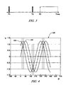
- FIG. 3 is an exemplary timing diagram indicating when the position determination system monitors the handwheel position during an ignition off state of the vehicle;
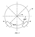
- FIG. 4 is a graph of first and second signals generated by first and second position sensors utilized in the position determination system of FIG. 1 ;
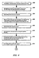
- FIG. 5 is a block diagram illustrating exemplary positions of first and second position sensors utilized in the position determination system of FIG. 1 ;
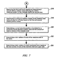
- FIGS. 6 and 7 are flowcharts of a method for determining an absolute rotational position of a rotatable shaft of a motor in the electric power system of FIG. 1 in accordance with another exemplary embodiment.
- FIG. 8 is a flowchart of another method for determining an absolute rotational position of a rotatable shaft of a motor in the electric power system of FIG. 1 in accordance with another exemplary embodiment.
- ignition off state corresponds to a power off state of an electric power steering system
- ignition on state corresponds to a power on state of an electric power steering system
- the handwheel 20 is operably coupled to the electric power steering system 24. Rotation of the handwheel 20 induces the electric power steering system 24 to cause rotation of a rotatable motor shaft 42 operably coupled to a rack-and-pinion assembly to move an operational position of vehicle wheels.
- the electric power steering system 24 includes an electric motor 40 having the rotatable shaft 42 and a magnet 44 coupled to the rotatable shaft 42.
- the rotatable shaft 42 is operably coupled via a gear assembly to a rack-and-pinion assembly for controlling an operational position of vehicle wheels.
- the position determination system 30 is provided to determine an absolute rotational position of the rotatable shaft 42 of the motor 40 when the vehicle 10 has an ignition off state.
- the system 30 includes first and second position sensors 60, 62, a microprocessor 66, a timer circuit 70, a memory device 74, a power source 80, a voltage regulator 82, a switch 84, a comparator 90, and a main controller 92.
- the first and second position sensors 60, 62 are configured to generate first and second signals indicative of a relative position of the rotatable shaft 42 of the motor 40.
- the first and second position sensors 60, 62 are Hall effect sensors that generate the first and second signals, respectively, in response to detecting a magnetic field from the magnet 44 coupled to the rotatable shaft 42.
- the first and second position sensors 60, 62 are disposed 90 degrees apart from one another about a central axis 99 of the rotatable shaft 42.
- the first position sensor 60 can generate a first signal over time represented by signal curve 122 as the rotatable shaft 42 and the magnet 44 are rotated.
- the second position sensor 62 can generate a second signal over time represented by signal curve 124 as the rotatable shaft 42 and the magnet 44 are rotated.
- the timer circuit 70 is operably coupled to the microprocessor 66.
- the timer circuit 70 is configured to periodically generate a control signal that activates the microprocessor 66 when the vehicle 10 has an ignition off state.
- the timer circuit 70 generates the control signal every 256 milliseconds to activate the microprocessor 66. Of course, other time intervals are contemplated.
- the memory device 74 is operably coupled to the microprocessor 66.
- the microprocessor 66 is configured to store data values in the memory device 74 as will be explained in greater detail below.
- the power source 80 is configured to output a voltage which is regulated utilizing the voltage regulator 82.
- the voltage regulator 82 outputs an operational voltage that is received by the microprocessor 66 for powering the microprocessor 66.
- the switch 84 is coupled between the voltage regulator 82 and the position sensors 60, 62.
- an operational voltage from the voltage regulator 82 is supplied to the first and second position sensors 60, 62 to energize the position sensors 60, 62.
- an operational voltage from the voltage regulator 82 is removed from the first and second position sensors 60, 62 to de-energize the position sensors 60, 62.
- the switch 84 is a p-channel MOSFET that is switched to either the closed operational position or the open operational position by control signals from the microprocessor 66.
- the comparator 90 is configured to compare the first, second, and third back electromotive force voltages from first, second, and third phases, respectively, of the motor 40 to a reference voltage.
- the comparator 90 outputs an interrupt/control signal that is received by the microprocessor 66 when either the first back electromotive force voltage is greater than the reference voltage, or the second back electromotive force voltage is greater than the reference voltage, or the third back electromotive force voltage is greater than the reference voltage, indicating that a rotational speed of the shaft 42 is greater than a threshold rotational speed.
- comparator 90 is configured to compare the first and second back electromotive force voltages from first and second phases, respectively, of the motor 40 to the reference voltage.
- the microprocessor 66 wakes up from a low power sleep mode to determine the absolute rotational position of the shaft 42.
- the microprocessor 66 is operably coupled to the voltage regulator 82, the switch 84, the first and second position sensors 60, 62, the timer circuit 70, the memory device 74, the comparator 90, and the main controller 92.
- the microprocessor 66 determines the absolute rotational position of the shaft 42 during the vehicle ignition off state by being periodically activated by a control signal from the timer circuit 70 or by being activated by an interrupt/control signal from the comparator 90.
- the microprocessor 66 is periodically activated by the timer circuit 70 to periodically monitor the first and second position signals from the first and second position sensors 60, 62 during the ignition off state of the vehicle 10.
- the timer circuit 70 can wake up or activate the microprocessor 66 at times T1 and T2 representing a 256 millisecond time interval between activations.
- the microprocessor 66 measures the first and second position signals from the position sensors 60, 62 for 50-100 ⁇ second and then is de-activated.
- the microprocessor 66 has an activation duty cycle that is defined by a desired quiescent current draw of the microprocessor 66 and a desired maximum speed of the shaft 42.
- the microprocessor 66 can be activated at a time T3 by an interrupt/control signal from the comparator 90. The operation of the microprocessor 66 will be discussed in greater detail below.
- FIGS. 2 , 6 and 7 a flowchart of a method for determining an absolute rotational position of the rotatable shaft 42 of the motor 40 in the electric power steering system 24 in accordance with an exemplary embodiment will be explained.
- the timer circuit 70 generates a control signal to activate the microprocessor 66 during an ignition off state of the vehicle 10.
- the microprocessor 66 generates a control signal that induces the switch 84 to supply an operational voltage to the first and second position sensors 60, 62 to energize the first and second position sensors 60, 62 at a first time when the microprocessor 66 is activated.
- the first and second position sensors 60, 62 generate first and second signals, respectively, indicative of a relative rotational position of the rotatable shaft 42 at the first time.
- the microprocessor 66 measures the first and second signals and determines a first relative position value indicating the relative rotational position of the rotatable shaft 42 at the first time and stores the first relative position value in the memory device 74.
- the microprocessor 66 deactivates itself after storing the first relative position value in the memory device 74.
- the timer circuit 70 generates a control signal to activate the microprocessor 66 during the ignition off state of the vehicle 10.
- the microprocessor 66 generates a control signal that induces the switch 84 to supply an operational voltage to the first and second position sensors 60, 62 to energize the first and second position sensors 60, 62 at a second time after the first time and after the microprocessor 66 was deactivated.
- the first and second position sensors 60, 62 generate third and fourth signals, respectively, indicative of a relative rotational position of the rotatable shaft 42 at the second time.
- the microprocessor 66 measures the third and fourth signals and determines a second relative position value indicating the relative rotational position of the rotatable shaft 42 at the second time based on the third and fourth signals, and stores the second relative position value in the memory device 74.
- the microprocessor 66 determines an amount of relative rotation of the rotatable shaft 42 during the ignition off state based on the first and second relative position values, and stores the amount of relative rotation in the memory device 74.
- the microprocessor 66 determines a current absolute position value indicating a current absolute rotational position of the rotatable shaft 42 based on a previously stored absolute position value and the amount of relative rotation of the rotatable shaft 42, and stores the current absolute position value in the memory device 74.
- the microprocessor 66 determines a total number of turns of the rotatable shaft 42 of the motor 40 by dividing the current absolute rotational position of the rotatable shaft 42 by 360 degrees, and stores the total number of turns of the rotatable shaft 42 of the motor 40 in the memory device 74.
- the microprocessor 66 determines a total number of vehicle handwheel turns based on the total number of turns of the rotatable shaft 42 of the motor 40 and a gear ratio associated with the electric power steering system, and stores the total number of vehicle handwheel turns in the memory device 74.
- FIGS. 2 and 8 a flowchart of another method for determining an absolute rotational position of the rotatable shaft 42 of the motor 40 in the electric power steering system 24 in accordance with another exemplary embodiment will be explained.
- the comparator 90 compares first and second back electromotive force voltages from first and second phases, respectively, of the motor 40 to a reference voltage, and outputs a control signal when either the first back electromotive force voltage is greater than the reference voltage or the second back electromotive force voltage is greater than the reference voltage.
- the microprocessor 66 is activated in response to the control signal during an ignition off state of the vehicle 10.
- the microprocessor 66 generates a control signal that induces the switch 84 to supply an operational voltage to the first and second position sensors 60, 62 to energize the first and second position sensors 60, 62 at a first time when the microprocessor 66 is activated.
- the first and second position sensors 60, 62 generate first and second signals, respectively, indicative of a relative rotational position of the rotatable shaft 42 over time.
- the microprocessor 66 measures the first and second signals and determines a first relative position value indicating a relative rotational position of the rotatable shaft 42 at the first time, and stores the first relative position value in the memory device 74.
- the microprocessor 66 measures the first and second signals and determines a second relative position value indicating a relative position of the rotatable shaft 42 at a second time and stores the second relative position value in the memory device 74.
- the second time is after the first time.
- the microprocessor 66 determines an amount of relative rotation of the rotatable shaft 42 during the ignition off state based on the first and second relative position values, and stores the amount of relative rotation in the memory device 74.
- the microprocessor 66 determines a current absolute position value indicating a current absolute rotational position of the rotatable shaft 42 based on a previously stored absolute position value and the amount of relative rotation of the rotatable shaft 42, and stores the current absolute position value in the memory device 74.
- the microprocessor 66 determines a total number of turns of the rotatable shaft 42 of the motor 40 by dividing the current absolute rotational position of the rotatable shaft 42 by 360 degrees, and stores the total number of turns of the rotatable shaft 42 of the motor 40 in the memory device 74.
- the microprocessor 66 determines a total number of vehicle handwheel turns based on the total number of turns of the rotatable shaft 42 of the motor 40 and a gear ratio associated with the electric power steering system, and stores the total number of vehicle handwheel turns in the memory device 74.
- the microprocessor 66 can operate in a low power mode drawing less than 70 ⁇ A when there is no movement of the shaft 42.
- the microprocessor 66 can also monitor rotational speeds of the shaft 42 up to 11,000 RPM and has a resolution of one-half of a mechanical revolution of the shaft 42.
- the microprocessor 66 can determine +/- 1080° of handwheel movement (e.g., three handwheel revolutions).
Abstract
Description
- The application claims the benefit of United States Provisional Application, serial number
61/334,835, filed May 14, 2010 - The subject application relates to a system and a method for determining an absolute rotational position of a motor shaft in an electric steering system when a vehicle has an ignition off state.
- A vehicle electric power steering system has utilized a microprocessor that monitors a motor shaft position in the electric power steering system. The microprocessor, however, is turned off when the ignition of the vehicle is off (i.e., an ignition off state of the vehicle). Accordingly, if a vehicle operator turns the steering wheel during the ignition off state, when the microprocessor is subsequently turned on during an ignition on state, the microprocessor may not be able to accurate determine an absolute rotational position of the motor shaft.
- Accordingly, it is desirable to provide a system and a method for determining an absolute rotational position of a rotatable shaft of a motor in an electric power steering system during an ignition off state of the vehicle.
- A system for determining an absolute rotational position of a rotatable shaft of a motor in an electric power steering system of a vehicle in accordance with an exemplary embodiment is provided. The system includes a microprocessor configured to be periodically activated during an ignition off state of the vehicle by a timer circuit. The microprocessor is further configured to energize first and second position sensors at a first time when the microprocessor is activated. The first and second position sensors are configured to generate first and second signals, respectively, indicative of a relative rotational position of the rotatable shaft at the first time. The microprocessor is further configured to measure the first and second signals and to determine a first relative position value indicating the relative rotational position of the rotatable shaft at the first time, and then to be deactivated. The microprocessor is further configured to energize the first and second position sensors at a second time when the microprocessor is activated. The second time is after the first time and is also after the microprocessor was deactivated. The first and second position sensors are further configured to generate third and fourth signals, respectively, indicative of a relative rotational position of the rotatable shaft at the second time. The microprocessor is further configured to measure the third and fourth signals and to determine a second relative position value indicating the relative rotational position of the rotatable shaft at the second time. The microprocessor is further configured to determine an amount of relative rotation of the rotatable shaft during the ignition off state based on the first and second relative position values. The microprocessor is further configured to determine a current absolute position value indicating a current absolute rotational position of the rotatable shaft based on a previously stored absolute position value and the amount of relative rotation of the rotatable shaft.
- A method for determining an absolute rotational position of a rotatable shaft of a motor in an electric power steering system of a vehicle in accordance with another exemplary embodiment is provided. The method includes periodically activating a microprocessor during an ignition off state of the vehicle utilizing a timer circuit. The method further includes energizing first and second position sensors at a first time when the microprocessor is activated, utilizing the microprocessor. The method further includes generating first and second signals, respectively, indicative of a relative rotational position of the rotatable shaft at the first time utilizing the first and second position sensors, respectively. The method further includes measuring the first and second signals and determining a first relative position value indicating the relative rotational position of the rotatable shaft at the first time utilizing the microprocessor. The method further includes deactivating the microprocessor after determining the first relative position value. The method further includes energizing the first and second position sensors at a second time when the microprocessor is activated, utilizing the microprocessor. The second time is after the first time and is also after the microprocessor was deactivated. The method further includes generating third and fourth signals, respectively, indicative of a relative rotational position of the rotatable shaft at the second time, utilizing the first and second position sensors, respectively. The method further includes measuring the third and fourth signals and determining a second relative position value indicating the relative rotational position of the rotatable shaft at the second time utilizing the microprocessor. The method further includes determining an amount of relative rotation of the rotatable shaft during the ignition off state based on the first and second relative position values utilizing the microprocessor. The method further includes determining a current absolute position value indicating a current absolute rotational position of the rotatable shaft based on a previously stored absolute position value and the amount of relative rotation of the rotatable shaft utilizing the microprocessor. The method further includes storing the current absolute position value in the memory device utilizing the microprocessor.
- A system for determining an absolute rotational position of a rotatable shaft of a motor in an electric power steering system of a vehicle in accordance with another exemplary embodiment is provided. The system includes a comparator configured to compare first and second back electromotive force voltages from first and second phases, respectively, of the motor to a reference voltage, and to output a control signal when either the first back electromotive force voltage is greater than the reference voltage or the second back electromotive force voltage is greater than the reference voltage. The microprocessor is configured to be activated in response to the control signal. The microprocessor is further configured to energize first and second position sensors at a first time when the microprocessor is activated. The first and second position sensors are configured to generate first and second signals, respectively, indicative of a relative rotational position of the rotatable shaft. The microprocessor is further configured to measure the first and second signals and to determine a first relative position value indicating a relative rotational position of the rotatable shaft at the first time. The microprocessor is further configured to measure the first and second signals and to determine a second relative position value indicating a relative position of the rotatable shaft at the second time. The second time is after the first time. The microprocessor is further configured to determine an amount of relative rotation of the rotatable shaft during the ignition off state based on the first and second relative position values. The microprocessor is further configured to determine a current absolute position value indicating a current absolute rotational position of the rotatable shaft based on a previously stored absolute position value and the amount of relative rotation of the rotatable shaft.
- A system for determining an absolute rotational position of a rotatable shaft of a motor in an electric power steering system having a power on state and a power off state in accordance with another exemplary embodiment is provided. The system includes a microprocessor configured to be periodically activated during the power off state of the system by a timer circuit. The microprocessor is further configured to energize a plurality of position sensors when the microprocessor is activated. The plurality of position sensors are configured to generate at least a first signal and a second signal indicative of a relative rotational position of the rotatable shaft at a first time. The plurality of position sensors are further configured to generate at least a third signal and a fourth signal indicative of a relative rotational position of the rotatable shaft at the second time. The second time is different than the first time. The microprocessor is further configured to determine an amount of relative rotation of the rotatable shaft during the power off state based on a difference between the relative rotational position at the first time and the relative rotational position at the second time. The microprocessor is further configured to determine a current absolute rotational position of the rotatable shaft based on an absolute position value stored during the power on state and the amount of relative rotation of the rotatable shaft.
- A method for determining an absolute rotational position of a rotatable shaft of a motor in an electric power steering system having a power on state and a power off state in accordance with another exemplary embodiment is provided. The method includes periodically activating a microprocessor during the power off state of the system. The method further includes determining a first relative position value indicating the relative rotational position of the rotatable shaft at a first time during the power off state utilizing the microprocessor. The method further includes deactivating the microprocessor after determining the first relative position value. The method further includes determining a second relative position value indicating the relative rotational position of the rotatable shaft at a second time during the power off state utilizing the microprocessor. The method further includes determining an amount of relative rotation of the rotatable shaft during the power off state based on the first and second relative position values. The method further includes determining a current absolute position value indicating a current absolute rotational position of the rotatable shaft by comparing an absolute position value stored during the power on state and the amount of relative rotation of the rotatable shaft utilizing the microprocessor. The method further includes storing the current absolute position value in the memory device.
- The above features and advantages and other features and advantages of the present invention are readily apparent from the following detailed description of the invention when taken in connection with the accompanying drawings.
- Other objects, features, advantages and details appear, by way of example only, in the following detailed description of embodiments, the detailed description referring to the drawings in which:
-
FIG. 1 is a block diagram of a vehicle having a handwheel, an electric power steering system, and a position determination system in accordance with an exemplary embodiment; -
FIG. 2 is a block diagram of the electric power steering system and the position determination system shown inFIG. 1 ; -
FIG. 3 is an exemplary timing diagram indicating when the position determination system monitors the handwheel position during an ignition off state of the vehicle; -
FIG. 4 is a graph of first and second signals generated by first and second position sensors utilized in the position determination system ofFIG. 1 ; -
FIG. 5 is a block diagram illustrating exemplary positions of first and second position sensors utilized in the position determination system ofFIG. 1 ; -
FIGS. 6 and7 are flowcharts of a method for determining an absolute rotational position of a rotatable shaft of a motor in the electric power system ofFIG. 1 in accordance with another exemplary embodiment; and -
FIG. 8 is a flowchart of another method for determining an absolute rotational position of a rotatable shaft of a motor in the electric power system ofFIG. 1 in accordance with another exemplary embodiment. - Referring now to
FIGS. 1 and 2 , avehicle 10 having ahandwheel 20, an electricpower steering system 24, and aposition determination system 30 in accordance with an exemplary embodiment is illustrated. The term "ignition off state" used herein corresponds to a power off state of an electric power steering system, and the term "ignition on state" corresponds to a power on state of an electric power steering system. - The
handwheel 20 is operably coupled to the electricpower steering system 24. Rotation of thehandwheel 20 induces the electricpower steering system 24 to cause rotation of arotatable motor shaft 42 operably coupled to a rack-and-pinion assembly to move an operational position of vehicle wheels. - The electric
power steering system 24 includes anelectric motor 40 having therotatable shaft 42 and amagnet 44 coupled to therotatable shaft 42. In one embodiment, therotatable shaft 42 is operably coupled via a gear assembly to a rack-and-pinion assembly for controlling an operational position of vehicle wheels. - The
position determination system 30 is provided to determine an absolute rotational position of therotatable shaft 42 of themotor 40 when thevehicle 10 has an ignition off state. Thesystem 30 includes first andsecond position sensors microprocessor 66, atimer circuit 70, amemory device 74, apower source 80, avoltage regulator 82, aswitch 84, acomparator 90, and amain controller 92. - Referring to
FIGS. 2 ,4 and5 , the first andsecond position sensors rotatable shaft 42 of themotor 40. In one exemplary embodiment, the first andsecond position sensors magnet 44 coupled to therotatable shaft 42. In one exemplary embodiment, the first andsecond position sensors central axis 99 of therotatable shaft 42. As shown inFIG. 4 , thefirst position sensor 60 can generate a first signal over time represented bysignal curve 122 as therotatable shaft 42 and themagnet 44 are rotated. Also, thesecond position sensor 62 can generate a second signal over time represented bysignal curve 124 as therotatable shaft 42 and themagnet 44 are rotated. - The
timer circuit 70 is operably coupled to themicroprocessor 66. Thetimer circuit 70 is configured to periodically generate a control signal that activates themicroprocessor 66 when thevehicle 10 has an ignition off state. In one exemplary embodiment, thetimer circuit 70 generates the control signal every 256 milliseconds to activate themicroprocessor 66. Of course, other time intervals are contemplated. - The
memory device 74 is operably coupled to themicroprocessor 66. Themicroprocessor 66 is configured to store data values in thememory device 74 as will be explained in greater detail below. - The
power source 80 is configured to output a voltage which is regulated utilizing thevoltage regulator 82. Thevoltage regulator 82 outputs an operational voltage that is received by themicroprocessor 66 for powering themicroprocessor 66. - The
switch 84 is coupled between thevoltage regulator 82 and theposition sensors switch 84 has a closed operational position, an operational voltage from thevoltage regulator 82 is supplied to the first andsecond position sensors position sensors switch 84 has an open operational position, an operational voltage from thevoltage regulator 82 is removed from the first andsecond position sensors position sensors switch 84 is a p-channel MOSFET that is switched to either the closed operational position or the open operational position by control signals from themicroprocessor 66. - The
comparator 90 is configured to compare the first, second, and third back electromotive force voltages from first, second, and third phases, respectively, of themotor 40 to a reference voltage. Thecomparator 90 outputs an interrupt/control signal that is received by themicroprocessor 66 when either the first back electromotive force voltage is greater than the reference voltage, or the second back electromotive force voltage is greater than the reference voltage, or the third back electromotive force voltage is greater than the reference voltage, indicating that a rotational speed of theshaft 42 is greater than a threshold rotational speed. Of course, in an alternative embodiment,comparator 90 is configured to compare the first and second back electromotive force voltages from first and second phases, respectively, of themotor 40 to the reference voltage. When themicroprocessor 66 receives the interrupt/control signal from thecomparator 90, themicroprocessor 66 wakes up from a low power sleep mode to determine the absolute rotational position of theshaft 42. - Referring to
FIGS. 2 and3 , themicroprocessor 66 is operably coupled to thevoltage regulator 82, theswitch 84, the first andsecond position sensors timer circuit 70, thememory device 74, thecomparator 90, and themain controller 92. Themicroprocessor 66 determines the absolute rotational position of theshaft 42 during the vehicle ignition off state by being periodically activated by a control signal from thetimer circuit 70 or by being activated by an interrupt/control signal from thecomparator 90. In particular, in one exemplary embodiment, themicroprocessor 66 is periodically activated by thetimer circuit 70 to periodically monitor the first and second position signals from the first andsecond position sensors vehicle 10. For example, thetimer circuit 70 can wake up or activate themicroprocessor 66 at times T1 and T2 representing a 256 millisecond time interval between activations. After, themicroprocessor 66 is activated, themicroprocessor 66 measures the first and second position signals from theposition sensors microprocessor 66 has an activation duty cycle that is defined by a desired quiescent current draw of themicroprocessor 66 and a desired maximum speed of theshaft 42. Also, themicroprocessor 66 can be activated at a time T3 by an interrupt/control signal from thecomparator 90. The operation of themicroprocessor 66 will be discussed in greater detail below. - Referring to
FIGS. 2 ,6 and7 , a flowchart of a method for determining an absolute rotational position of therotatable shaft 42 of themotor 40 in the electricpower steering system 24 in accordance with an exemplary embodiment will be explained. - At
step 200, thetimer circuit 70 generates a control signal to activate themicroprocessor 66 during an ignition off state of thevehicle 10. - At
step 202, themicroprocessor 66 generates a control signal that induces theswitch 84 to supply an operational voltage to the first andsecond position sensors second position sensors microprocessor 66 is activated. - At
step 204, the first andsecond position sensors rotatable shaft 42 at the first time. - At
step 206, themicroprocessor 66 measures the first and second signals and determines a first relative position value indicating the relative rotational position of therotatable shaft 42 at the first time and stores the first relative position value in thememory device 74. In one exemplary embodiment, the first relative position value is determined utilizing the following equation: first relative position value = ArcTan (amplitude ofsignal curve 124 at the first time / amplitude ofsignal curve 122 at the first time) wherein signal curves 122, 124 are shown inFIG. 4 . - At
step 208, themicroprocessor 66 deactivates itself after storing the first relative position value in thememory device 74. - At
step 210, thetimer circuit 70 generates a control signal to activate themicroprocessor 66 during the ignition off state of thevehicle 10. - At
step 212, themicroprocessor 66 generates a control signal that induces theswitch 84 to supply an operational voltage to the first andsecond position sensors second position sensors microprocessor 66 was deactivated. - At
step 124, the first andsecond position sensors rotatable shaft 42 at the second time. - At
step 216, themicroprocessor 66 measures the third and fourth signals and determines a second relative position value indicating the relative rotational position of therotatable shaft 42 at the second time based on the third and fourth signals, and stores the second relative position value in thememory device 74. - At
step 218, themicroprocessor 66 determines an amount of relative rotation of therotatable shaft 42 during the ignition off state based on the first and second relative position values, and stores the amount of relative rotation in thememory device 74. In one exemplary embodiment, the amount of relative rotation is determined utilizing the following equation: amount of relative rotation = first relative position value - second relative position value. - At
step 220, themicroprocessor 66 determines a current absolute position value indicating a current absolute rotational position of therotatable shaft 42 based on a previously stored absolute position value and the amount of relative rotation of therotatable shaft 42, and stores the current absolute position value in thememory device 74. In particular, the current absolute position value is calculated utilizing the following equation: current absolute position value = previously stored absolute position value + amount of relative rotation of therotatable shaft 42. - At
step 222, themicroprocessor 66 determines a total number of turns of therotatable shaft 42 of themotor 40 by dividing the current absolute rotational position of therotatable shaft 42 by 360 degrees, and stores the total number of turns of therotatable shaft 42 of themotor 40 in thememory device 74. In particular, the total number of turns of therotatable shaft 42 is calculated utilizing the following equation: total number of turns of therotatable shaft 42 = current absolute rotational position of therotatable shaft 42 / 360 degrees. - At
step 224, themicroprocessor 66 determines a total number of vehicle handwheel turns based on the total number of turns of therotatable shaft 42 of themotor 40 and a gear ratio associated with the electric power steering system, and stores the total number of vehicle handwheel turns in thememory device 74. In one exemplary embodiment, the total number of vehicle handwheel turns is determined utilizing the following equation: total number of vehicle handwheel turns = the total number of turns of therotatable shaft 42 of themotor 40 / gear ratio associated with the electric power steering system. - Referring to
FIGS. 2 and8 , a flowchart of another method for determining an absolute rotational position of therotatable shaft 42 of themotor 40 in the electricpower steering system 24 in accordance with another exemplary embodiment will be explained. - At
step 250, thecomparator 90 compares first and second back electromotive force voltages from first and second phases, respectively, of themotor 40 to a reference voltage, and outputs a control signal when either the first back electromotive force voltage is greater than the reference voltage or the second back electromotive force voltage is greater than the reference voltage. - At
step 252, themicroprocessor 66 is activated in response to the control signal during an ignition off state of thevehicle 10. - At
step 254, themicroprocessor 66 generates a control signal that induces theswitch 84 to supply an operational voltage to the first andsecond position sensors second position sensors microprocessor 66 is activated. - At
step 256, the first andsecond position sensors rotatable shaft 42 over time. - At
step 258, themicroprocessor 66 measures the first and second signals and determines a first relative position value indicating a relative rotational position of therotatable shaft 42 at the first time, and stores the first relative position value in thememory device 74. - At
step 260, themicroprocessor 66 measures the first and second signals and determines a second relative position value indicating a relative position of therotatable shaft 42 at a second time and stores the second relative position value in thememory device 74. The second time is after the first time. - At
step 262, themicroprocessor 66 determines an amount of relative rotation of therotatable shaft 42 during the ignition off state based on the first and second relative position values, and stores the amount of relative rotation in thememory device 74. - At
step 264, themicroprocessor 66 determines a current absolute position value indicating a current absolute rotational position of therotatable shaft 42 based on a previously stored absolute position value and the amount of relative rotation of therotatable shaft 42, and stores the current absolute position value in thememory device 74. - At
step 266, themicroprocessor 66 determines a total number of turns of therotatable shaft 42 of themotor 40 by dividing the current absolute rotational position of therotatable shaft 42 by 360 degrees, and stores the total number of turns of therotatable shaft 42 of themotor 40 in thememory device 74. - At
step 268, themicroprocessor 66 determines a total number of vehicle handwheel turns based on the total number of turns of therotatable shaft 42 of themotor 40 and a gear ratio associated with the electric power steering system, and stores the total number of vehicle handwheel turns in thememory device 74. - It should be noted that the
microprocessor 66 can operate in a low power mode drawing less than 70µA when there is no movement of theshaft 42. Themicroprocessor 66 can also monitor rotational speeds of theshaft 42 up to 11,000 RPM and has a resolution of one-half of a mechanical revolution of theshaft 42. In addition, themicroprocessor 66 can determine +/- 1080° of handwheel movement (e.g., three handwheel revolutions). - While the invention has been described with reference to exemplary embodiments, it will be understood by those skilled in the art that various changes may be made and equivalents may be substituted for elements thereof without departing from the scope of the invention. In addition, many modifications may be made to adapt a particular situation or material to the teachings of the invention without departing from the essential scope thereof. Therefore, it is intended that the invention not be limited to the particular embodiments disclosed or contemplated for carrying out this invention, but that the invention will include all embodiments falling within the scope of the present application.
Claims (15)
- A system for determining an absolute rotational position of a rotatable shaft of a motor in an electric power steering system of a vehicle, comprising:a microprocessor configured to be periodically activated during an ignition off state of the vehicle by a timer circuit, the microprocessor further configured to energize first and second position sensors at a first time when the microprocessor is activated;the first and second position sensors configured to generate first and second signals, respectively, indicative of a relative rotational position of the rotatable shaft at the first time;the microprocessor further configured to measure the first and second signals and to determine a first relative position value indicating the relative rotational position of the rotatable shaft at the first time, and then to be deactivated, the microprocessor further configured to energize the first and second position sensors at a second time when the microprocessor is activated, the second time being after the first time and after the microprocessor was deactivated;the first and second position sensors further configured to generate third and fourth signals, respectively, indicative of a relative rotational position of the rotatable shaft at the second time;the microprocessor further configured to measure the third and fourth signals and to determine a second relative position value indicating the relative rotational position of the rotatable shaft at the second time, the microprocessor further configured to determine an amount of relative rotation of the rotatable shaft during the ignition off state based on the first and second relative position values, and the microprocessor further configured to determine a current absolute position value indicating a current absolute rotational position of the rotatable shaft based on a previously stored absolute position value and the amount of relative rotation of the rotatable shaft.
- The system of claim 1, wherein the microprocessor is further configured to determine a total number of turns of the rotatable shaft of the motor by dividing the current absolute rotational position of the rotatable shaft by 360 degrees.
- The system of claim 2, wherein the microprocessor is further configured to determine a total number of vehicle handwheel turns based on the total number of turns of the rotatable shaft of the motor and a gear ratio associated with the electric power steering system.
- The system of claim 1, wherein the first and second position sensors are first and second Hall effect sensors, respectively, that are configured to measure a magnetic field of a magnet that is coupled to the rotatable shaft, in particular
wherein the first and second Hall effect sensors are disposed 90 degrees apart from one another about a central axis of the rotatable shaft. - The system of claim 1, wherein the microprocessor is configured to energize the first and second position sensors at the first time by generating a control signal that induces a switch coupled to the first and second position sensors to supply an operational voltage to the first and second position sensors.
- The system of claim 1, wherein a time interval between activations of the microprocessor is utilized to reduce power consumption of the microprocessor.
- A method for determining an absolute rotational position of a rotatable shaft of a motor in an electric power steering system of a vehicle, comprising:periodically activating a microprocessor during an ignition off state of the vehicle utilizing a timer circuit;energizing first and second position sensors at a first time when the microprocessor is activated, utilizing the microprocessor;generating first and second signals, respectively, indicative of a relative rotational position of the rotatable shaft at the first time utilizing the first and second position sensors, respectively;measuring the first and second signals and determining a first relative position value indicating the relative rotational position of the rotatable shaft at the first time utilizing the microprocessor;deactivating the microprocessor after determining the first relative position value;energizing the first and second position sensors at a second time when the microprocessor is activated, utilizing the microprocessor, the second time being after the first time and after the microprocessor was deactivated;generating third and fourth signals, respectively, indicative of a relative rotational position of the rotatable shaft at the second time, utilizing the first and second position sensors, respectively;measuring the third and fourth signals and determining a second relative position value indicating the relative rotational position of the rotatable shaft at the second time utilizing the microprocessor;determining an amount of relative rotation of the rotatable shaft during the ignition off state based on the first and second relative position values utilizing the microprocessor;determining a current absolute position value indicating a current absolute rotational position of the rotatable shaft based on a previously stored absolute position value and the amount of relative rotation of the rotatable shaft utilizing the microprocessor; andstoring the current absolute position value in the memory device utilizing the microprocessor.
- The method of claim 7, further comprising determining a total number of turns of the rotatable shaft of the motor by dividing the current absolute rotational position of the rotatable shaft by 360 degrees.
- The method of claim 8, further comprising determining a total number of vehicle handwheel turns based on the total number of turns of the rotatable shaft of the motor and a gear ratio associated with the electric power steering system, utilizing the microprocessor.
- The method of claim 7, wherein the first and second position sensors are first and second Hall effect sensors, respectively, that are configured to measure a magnetic field of a magnet that is coupled to the rotatable shaft, in particular
wherein the first and second Hall effect sensors are disposed 90 degrees apart from one another about a central axis of the rotatable shaft. - The method of claim 7, further comprising energizing the first and second position sensors at the first time by generating a control signal which induces a switch coupled to the first and second position sensors to supply an operational voltage to the first and second position sensors utilizing the microprocessor.
- The method of claim 7, wherein a time interval between activations of the microprocessor is utilized to reduce power consumption of the microprocessor.
- A system for determining an absolute rotational position of a rotatable shaft of a motor in an electric power steering system of a vehicle, comprising:a comparator configured to compare first and second back electromotive force voltages from first and second phases, respectively, of the motor to a reference voltage, and to output a control signal when either the first back electromotive force voltage is greater than the reference voltage or the second back electromotive force voltage is greater than the reference voltage;the microprocessor configured to be activated in response to the control signal;the microprocessor further configured to energize first and second position sensors at a first time when the microprocessor is activated;the first and second position sensors configured to generate first and second signals, respectively, indicative of a relative rotational position of the rotatable shaft;the microprocessor further configured to measure the first and second signals and to determine a first relative position value indicating a relative rotational position of the rotatable shaft at the first time;the microprocessor further configured to measure the first and second signals and to determine a second relative position value indicating a relative position of the rotatable shaft at the second time, the second time being after the first time;the microprocessor further configured to determine an amount of relative rotation of the rotatable shaft during the ignition off state based on the first and second relative position values; andthe microprocessor further configured to determine a current absolute position value indicating a current absolute rotational position of the rotatable shaft based on a previously stored absolute position value and the amount of relative rotation of the rotatable shaft.
- A system for determining an absolute rotational position of a rotatable shaft of a motor in an electric power steering system having a power on state and a power off state, comprising:a microprocessor configured to be periodically activated during the power off state of the system by a timer circuit, the microprocessor further configured to energize a plurality of position sensors when the microprocessor is activated;the plurality of position sensors configured to generate at least a first signal and a second signal indicative of a relative rotational position of the rotatable shaft at a first time;the plurality of position sensors further configured to generate at least a third signal and a fourth signal indicative of a relative rotational position of the rotatable shaft at the second time, the second time being different than the first time; andthe microprocessor further configured to determine an amount of relative rotation of the rotatable shaft during the power off state based on a difference between the relative rotational position at the first time and the relative rotational position at the second time, and the microprocessor further configured to determine a current absolute rotational position of the rotatable shaft based on an absolute position value stored during the power on state and the amount of relative rotation of the rotatable shaft.
- A method for determining an absolute rotational position of a rotatable shaft of a motor in an electric power steering system having a power on state and a power off state, comprising:periodically activating a microprocessor during the power off state of the system;determining a first relative position value indicating the relative rotational position of the rotatable shaft at a first time during the power off state utilizing the microprocessor;deactivating the microprocessor after determining the first relative position value;determining a second relative position value indicating the relative rotational position of the rotatable shaft at a second time during the power off state utilizing the microprocessor;determining an amount of relative rotation of the rotatable shaft during the power off state based on the first and second relative position values;determining a current absolute position value indicating a current absolute rotational position of the rotatable shaft by comparing an absolute position value stored during the power on state and the amount of relative rotation of the rotatable shaft utilizing the microprocessor; andstoring the current absolute position value in the memory device.
Applications Claiming Priority (1)
| Application Number | Priority Date | Filing Date | Title |
|---|---|---|---|
| US33483510P | 2010-05-14 | 2010-05-14 |
Publications (3)
| Publication Number | Publication Date |
|---|---|
| EP2386465A2 true EP2386465A2 (en) | 2011-11-16 |
| EP2386465A3 EP2386465A3 (en) | 2012-10-10 |
| EP2386465B1 EP2386465B1 (en) | 2014-07-09 |
Family
ID=44117130
Family Applications (1)
| Application Number | Title | Priority Date | Filing Date |
|---|---|---|---|
| EP11004000.3A Active EP2386465B1 (en) | 2010-05-14 | 2011-05-13 | System and method for determining an absolute position of a motor shaft in an electric steering system |
Country Status (2)
| Country | Link |
|---|---|
| US (1) | US8862328B2 (en) |
| EP (1) | EP2386465B1 (en) |
Cited By (3)
| Publication number | Priority date | Publication date | Assignee | Title |
|---|---|---|---|---|
| EP2998197A1 (en) * | 2014-08-11 | 2016-03-23 | Steering Solutions IP Holding Corporation | Wake-up circuit in an electric steering system |
| EP2853471A4 (en) * | 2012-05-22 | 2016-07-06 | Nsk Ltd | Vehicle steering angle detection device and electric power steering device |
| US9434407B2 (en) | 2010-05-14 | 2016-09-06 | Steering Solutions Ip Holding Corporation | Wake-up circuit in an electric steering system |
Families Citing this family (15)
| Publication number | Priority date | Publication date | Assignee | Title |
|---|---|---|---|---|
| US8390240B2 (en) | 2007-08-06 | 2013-03-05 | GM Global Technology Operations LLC | Absolute position sensor for field-oriented control of an induction motor |
| US8179127B2 (en) * | 2007-11-06 | 2012-05-15 | GM Global Technology Operations LLC | Method and apparatus to monitor position of a rotatable shaft |
| US9106175B2 (en) * | 2010-11-23 | 2015-08-11 | Steering Solutions Ip Holding Corporation | Diagnostic system and method for an electric power steering system |
| US20130342190A1 (en) * | 2011-08-17 | 2013-12-26 | Nicholas William Payne | Through Shaft Rotary Position Sensor |
| US9625534B2 (en) * | 2012-11-21 | 2017-04-18 | Allegro Microsystems, Llc | Systems and methods for detection of magnetic fields |
| EP2799310B1 (en) | 2013-04-30 | 2016-06-08 | Steering Solutions IP Holding Corporation | Providing assist torque without hand wheel torque sensor |
| US10144445B2 (en) | 2014-09-15 | 2018-12-04 | Steering Solutions Ip Holding Corporation | Modified static tire model for providing assist without a torque sensor for zero to low vehicle speeds |
| US10336363B2 (en) | 2015-09-03 | 2019-07-02 | Steering Solutions Ip Holding Corporation | Disabling controlled velocity return based on torque gradient and desired velocity error |
| US10464594B2 (en) * | 2015-09-03 | 2019-11-05 | Steering Solutions Ip Holding Corporation | Model based driver torque estimation |
| US10155534B2 (en) | 2016-06-14 | 2018-12-18 | Steering Solutions Ip Holding Corporation | Driver intent estimation without using torque sensor signal |
| JP7076683B2 (en) * | 2016-06-27 | 2022-05-30 | Smc株式会社 | Position detector |
| US10613113B2 (en) * | 2016-06-27 | 2020-04-07 | Smc Corporation | Position detecting device |
| JP6984176B2 (en) * | 2017-05-26 | 2021-12-17 | 株式会社ジェイテクト | Rotation monitoring circuit |
| KR20190001964A (en) * | 2017-06-28 | 2019-01-08 | 현대자동차주식회사 | Steering apparatus for vehivcle and controlling method therefor |
| US11180186B2 (en) * | 2018-04-05 | 2021-11-23 | Steering Solutions Ip Holding Corporation | Disturbance feedforward compensation for position control in steering systems |
Citations (2)
| Publication number | Priority date | Publication date | Assignee | Title |
|---|---|---|---|---|
| DE102006042104A1 (en) * | 2005-09-24 | 2007-04-12 | Zf Lenksysteme Gmbh | Motor vehicle steering system has servomotor to regulate wheel lock angle and sensor to monitor its shaft rotation |
| DE102006014700A1 (en) * | 2006-03-17 | 2007-09-27 | Continental Teves Ag & Co. Ohg | Steering angle sensor system and method for measuring a steering angle |
Family Cites Families (22)
| Publication number | Priority date | Publication date | Assignee | Title |
|---|---|---|---|---|
| US5241270A (en) * | 1990-04-02 | 1993-08-31 | Kim Kwee Ng | Electronic compass using hall-effect sensors |
| US5936524A (en) * | 1996-05-02 | 1999-08-10 | Visonic Ltd. | Intrusion detector |
| US6364050B1 (en) * | 1999-01-15 | 2002-04-02 | Trw Lucas Varity Electric Steering Ltd. | Electrical power assisted steering assemblies |
| US6314355B1 (en) * | 1999-07-12 | 2001-11-06 | Alps Electric Co., Ltd. | Steering angle detecting mechanism |
| US6400142B1 (en) | 1999-08-31 | 2002-06-04 | Delphi Technologies, Inc. | Steering wheel position sensor |
| DE60024564T2 (en) * | 1999-11-01 | 2006-08-10 | Koninklijke Philips Electronics N.V. | Data circuit with a non-volatile memory and with an error-correcting circuit |
| US6498971B2 (en) | 2001-03-13 | 2002-12-24 | Delphi Technologies, Inc. | Apparatus for determining steer angle of a motor vehicle |
| US6864616B2 (en) * | 2001-10-09 | 2005-03-08 | General Electric Company | Method and apparatus for forming an electric motor having stacked laminations |
| US7307415B2 (en) * | 2002-02-14 | 2007-12-11 | Bvr Technologies Co. | Contactless angular position sensor and method for sensing angular position of a rotatable shaft |
| JP4518818B2 (en) | 2004-03-17 | 2010-08-04 | 三菱電機株式会社 | Torque sensor |
| US20060065471A1 (en) * | 2004-09-28 | 2006-03-30 | Delphi Technologies, Inc. | Electric power steering controller having integrated column controls |
| US7609952B2 (en) * | 2005-08-01 | 2009-10-27 | Scott Jezierski | Apparatus and method for remote viewing system |
| RU2278797C1 (en) | 2005-08-19 | 2006-06-27 | Открытое акционерное общество "Калужский завод электронных изделий" | Electromechanical steering booster and steering booster electric motor |
| JP2008030675A (en) * | 2006-07-31 | 2008-02-14 | Nsk Ltd | Electric power steering device |
| DE102006039257A1 (en) * | 2006-08-22 | 2008-02-28 | Robert Bosch Gmbh | Adjusting device for a movable body part of a motor vehicle and method for adjusting the movable body part |
| PL1992549T3 (en) * | 2007-05-18 | 2013-03-29 | Gm Global Tech Operations Llc | Method for determining an absolute rotational position of a Vehicle Steering Column |
| US8412145B2 (en) * | 2007-05-31 | 2013-04-02 | Telenav, Inc. | Mobile battery management system |
| US8179127B2 (en) * | 2007-11-06 | 2012-05-15 | GM Global Technology Operations LLC | Method and apparatus to monitor position of a rotatable shaft |
| US8224529B2 (en) * | 2008-06-20 | 2012-07-17 | Ford Global Technologies | Self powered steering wheel angle sensor |
| US8428822B2 (en) * | 2009-03-13 | 2013-04-23 | Honda Motor Co., Ltd. | Method of determining a steering angle in a motor vehicle |
| WO2010113820A1 (en) * | 2009-03-30 | 2010-10-07 | 日立金属株式会社 | Rotation angle detection device |
| US7966963B1 (en) * | 2009-09-25 | 2011-06-28 | Dalen Products, Inc. | Owl with intermittent powered movement |
-
2011
- 2011-05-12 US US13/106,031 patent/US8862328B2/en active Active
- 2011-05-13 EP EP11004000.3A patent/EP2386465B1/en active Active
Patent Citations (2)
| Publication number | Priority date | Publication date | Assignee | Title |
|---|---|---|---|---|
| DE102006042104A1 (en) * | 2005-09-24 | 2007-04-12 | Zf Lenksysteme Gmbh | Motor vehicle steering system has servomotor to regulate wheel lock angle and sensor to monitor its shaft rotation |
| DE102006014700A1 (en) * | 2006-03-17 | 2007-09-27 | Continental Teves Ag & Co. Ohg | Steering angle sensor system and method for measuring a steering angle |
Cited By (3)
| Publication number | Priority date | Publication date | Assignee | Title |
|---|---|---|---|---|
| US9434407B2 (en) | 2010-05-14 | 2016-09-06 | Steering Solutions Ip Holding Corporation | Wake-up circuit in an electric steering system |
| EP2853471A4 (en) * | 2012-05-22 | 2016-07-06 | Nsk Ltd | Vehicle steering angle detection device and electric power steering device |
| EP2998197A1 (en) * | 2014-08-11 | 2016-03-23 | Steering Solutions IP Holding Corporation | Wake-up circuit in an electric steering system |
Also Published As
| Publication number | Publication date |
|---|---|
| EP2386465B1 (en) | 2014-07-09 |
| US8862328B2 (en) | 2014-10-14 |
| US20110282552A1 (en) | 2011-11-17 |
| EP2386465A3 (en) | 2012-10-10 |
Similar Documents
| Publication | Publication Date | Title |
|---|---|---|
| US8862328B2 (en) | System and method for determining an absolute position of a motor shaft in an electric steering system | |
| KR101597906B1 (en) | Encoder | |
| US8558534B2 (en) | Rotational angle detection device and electric power steering system | |
| JP5389101B2 (en) | Motor control device | |
| WO2012132751A1 (en) | Device for detecting steering shaft rotation angle | |
| US10103657B2 (en) | Motor drive control apparatus, electric power steering apparatus, and vehicle | |
| US8224529B2 (en) | Self powered steering wheel angle sensor | |
| JPWO2014148087A1 (en) | Power steering device and control device for power steering device | |
| JP5339094B2 (en) | Electric power steering device | |
| JP2003202224A (en) | Rotation angle detector | |
| EP1684412A3 (en) | Synchronous motor drive unit and a driving method thereof | |
| US10177638B2 (en) | Rotor position encoder for an electronically commutated electric machine having a reference encoder | |
| US9434407B2 (en) | Wake-up circuit in an electric steering system | |
| JP2015049042A (en) | Rotation angle detector, and electric power steering device | |
| US8896257B2 (en) | Motor control device and out-of-step detecting method of stepping motor | |
| EP2998197B1 (en) | Wake-up circuit in an electric steering system | |
| JP2008259347A (en) | Motor control device | |
| JP2011259635A5 (en) | ||
| US10666172B2 (en) | Motor control device and motor control method | |
| CN113840981B (en) | Motor control device, motor control method, variable valve timing control device, variable valve timing control method, and variable valve timing control program | |
| JP5325696B2 (en) | Control device for controlling position of vehicle door mirror | |
| JP5626702B2 (en) | Electric power steering device | |
| JP2007127597A (en) | Rotation angle detector | |
| CN113353144A (en) | Electric power steering control device and control method |
Legal Events
| Date | Code | Title | Description |
|---|---|---|---|
| AK | Designated contracting states |
Kind code of ref document: A2 Designated state(s): AL AT BE BG CH CY CZ DE DK EE ES FI FR GB GR HR HU IE IS IT LI LT LU LV MC MK MT NL NO PL PT RO RS SE SI SK SM TR |
|
| AX | Request for extension of the european patent |
Extension state: BA ME |
|
| PUAI | Public reference made under article 153(3) epc to a published international application that has entered the european phase |
Free format text: ORIGINAL CODE: 0009012 |
|
| PUAL | Search report despatched |
Free format text: ORIGINAL CODE: 0009013 |
|
| AK | Designated contracting states |
Kind code of ref document: A3 Designated state(s): AL AT BE BG CH CY CZ DE DK EE ES FI FR GB GR HR HU IE IS IT LI LT LU LV MC MK MT NL NO PL PT RO RS SE SI SK SM TR |
|
| AX | Request for extension of the european patent |
Extension state: BA ME |
|
| RIC1 | Information provided on ipc code assigned before grant |
Ipc: B62D 15/02 20060101AFI20120906BHEP Ipc: B62D 5/04 20060101ALI20120906BHEP |
|
| 17P | Request for examination filed |
Effective date: 20130409 |
|
| 17Q | First examination report despatched |
Effective date: 20130812 |
|
| GRAP | Despatch of communication of intention to grant a patent |
Free format text: ORIGINAL CODE: EPIDOSNIGR1 |
|
| INTG | Intention to grant announced |
Effective date: 20140123 |
|
| RAP1 | Party data changed (applicant data changed or rights of an application transferred) |
Owner name: GM GLOBAL TECHNOLOGY OPERATIONS LLC Owner name: STEERING SOLUTIONS IP HOLDING CORPORATION |
|
| GRAS | Grant fee paid |
Free format text: ORIGINAL CODE: EPIDOSNIGR3 |
|
| GRAA | (expected) grant |
Free format text: ORIGINAL CODE: 0009210 |
|
| AK | Designated contracting states |
Kind code of ref document: B1 Designated state(s): AL AT BE BG CH CY CZ DE DK EE ES FI FR GB GR HR HU IE IS IT LI LT LU LV MC MK MT NL NO PL PT RO RS SE SI SK SM TR |
|
| REG | Reference to a national code |
Ref country code: GB Ref legal event code: FG4D |
|
| REG | Reference to a national code |
Ref country code: CH Ref legal event code: EP Ref country code: AT Ref legal event code: REF Ref document number: 676464 Country of ref document: AT Kind code of ref document: T Effective date: 20140715 |
|
| REG | Reference to a national code |
Ref country code: IE Ref legal event code: FG4D |
|
| REG | Reference to a national code |
Ref country code: DE Ref legal event code: R096 Ref document number: 602011008210 Country of ref document: DE Effective date: 20140821 |
|
| REG | Reference to a national code |
Ref country code: AT Ref legal event code: MK05 Ref document number: 676464 Country of ref document: AT Kind code of ref document: T Effective date: 20140709 |
|
| REG | Reference to a national code |
Ref country code: NL Ref legal event code: VDEP Effective date: 20140709 |
|
| REG | Reference to a national code |
Ref country code: LT Ref legal event code: MG4D |
|
| PG25 | Lapsed in a contracting state [announced via postgrant information from national office to epo] |
Ref country code: FI Free format text: LAPSE BECAUSE OF FAILURE TO SUBMIT A TRANSLATION OF THE DESCRIPTION OR TO PAY THE FEE WITHIN THE PRESCRIBED TIME-LIMIT Effective date: 20140709 Ref country code: SE Free format text: LAPSE BECAUSE OF FAILURE TO SUBMIT A TRANSLATION OF THE DESCRIPTION OR TO PAY THE FEE WITHIN THE PRESCRIBED TIME-LIMIT Effective date: 20140709 Ref country code: PT Free format text: LAPSE BECAUSE OF FAILURE TO SUBMIT A TRANSLATION OF THE DESCRIPTION OR TO PAY THE FEE WITHIN THE PRESCRIBED TIME-LIMIT Effective date: 20141110 Ref country code: NO Free format text: LAPSE BECAUSE OF FAILURE TO SUBMIT A TRANSLATION OF THE DESCRIPTION OR TO PAY THE FEE WITHIN THE PRESCRIBED TIME-LIMIT Effective date: 20141009 Ref country code: LT Free format text: LAPSE BECAUSE OF FAILURE TO SUBMIT A TRANSLATION OF THE DESCRIPTION OR TO PAY THE FEE WITHIN THE PRESCRIBED TIME-LIMIT Effective date: 20140709 Ref country code: BG Free format text: LAPSE BECAUSE OF FAILURE TO SUBMIT A TRANSLATION OF THE DESCRIPTION OR TO PAY THE FEE WITHIN THE PRESCRIBED TIME-LIMIT Effective date: 20141009 Ref country code: ES Free format text: LAPSE BECAUSE OF FAILURE TO SUBMIT A TRANSLATION OF THE DESCRIPTION OR TO PAY THE FEE WITHIN THE PRESCRIBED TIME-LIMIT Effective date: 20140709 Ref country code: GR Free format text: LAPSE BECAUSE OF FAILURE TO SUBMIT A TRANSLATION OF THE DESCRIPTION OR TO PAY THE FEE WITHIN THE PRESCRIBED TIME-LIMIT Effective date: 20141010 |
|
| PG25 | Lapsed in a contracting state [announced via postgrant information from national office to epo] |
Ref country code: LV Free format text: LAPSE BECAUSE OF FAILURE TO SUBMIT A TRANSLATION OF THE DESCRIPTION OR TO PAY THE FEE WITHIN THE PRESCRIBED TIME-LIMIT Effective date: 20140709 Ref country code: CY Free format text: LAPSE BECAUSE OF FAILURE TO SUBMIT A TRANSLATION OF THE DESCRIPTION OR TO PAY THE FEE WITHIN THE PRESCRIBED TIME-LIMIT Effective date: 20140709 Ref country code: RS Free format text: LAPSE BECAUSE OF FAILURE TO SUBMIT A TRANSLATION OF THE DESCRIPTION OR TO PAY THE FEE WITHIN THE PRESCRIBED TIME-LIMIT Effective date: 20140709 Ref country code: AT Free format text: LAPSE BECAUSE OF FAILURE TO SUBMIT A TRANSLATION OF THE DESCRIPTION OR TO PAY THE FEE WITHIN THE PRESCRIBED TIME-LIMIT Effective date: 20140709 Ref country code: NL Free format text: LAPSE BECAUSE OF FAILURE TO SUBMIT A TRANSLATION OF THE DESCRIPTION OR TO PAY THE FEE WITHIN THE PRESCRIBED TIME-LIMIT Effective date: 20140709 Ref country code: HR Free format text: LAPSE BECAUSE OF FAILURE TO SUBMIT A TRANSLATION OF THE DESCRIPTION OR TO PAY THE FEE WITHIN THE PRESCRIBED TIME-LIMIT Effective date: 20140709 Ref country code: IS Free format text: LAPSE BECAUSE OF FAILURE TO SUBMIT A TRANSLATION OF THE DESCRIPTION OR TO PAY THE FEE WITHIN THE PRESCRIBED TIME-LIMIT Effective date: 20141109 Ref country code: PL Free format text: LAPSE BECAUSE OF FAILURE TO SUBMIT A TRANSLATION OF THE DESCRIPTION OR TO PAY THE FEE WITHIN THE PRESCRIBED TIME-LIMIT Effective date: 20140709 |
|
| REG | Reference to a national code |
Ref country code: DE Ref legal event code: R097 Ref document number: 602011008210 Country of ref document: DE |
|
| PG25 | Lapsed in a contracting state [announced via postgrant information from national office to epo] |
Ref country code: CZ Free format text: LAPSE BECAUSE OF FAILURE TO SUBMIT A TRANSLATION OF THE DESCRIPTION OR TO PAY THE FEE WITHIN THE PRESCRIBED TIME-LIMIT Effective date: 20140709 Ref country code: SK Free format text: LAPSE BECAUSE OF FAILURE TO SUBMIT A TRANSLATION OF THE DESCRIPTION OR TO PAY THE FEE WITHIN THE PRESCRIBED TIME-LIMIT Effective date: 20140709 Ref country code: IT Free format text: LAPSE BECAUSE OF FAILURE TO SUBMIT A TRANSLATION OF THE DESCRIPTION OR TO PAY THE FEE WITHIN THE PRESCRIBED TIME-LIMIT Effective date: 20140709 Ref country code: DK Free format text: LAPSE BECAUSE OF FAILURE TO SUBMIT A TRANSLATION OF THE DESCRIPTION OR TO PAY THE FEE WITHIN THE PRESCRIBED TIME-LIMIT Effective date: 20140709 Ref country code: EE Free format text: LAPSE BECAUSE OF FAILURE TO SUBMIT A TRANSLATION OF THE DESCRIPTION OR TO PAY THE FEE WITHIN THE PRESCRIBED TIME-LIMIT Effective date: 20140709 Ref country code: RO Free format text: LAPSE BECAUSE OF FAILURE TO SUBMIT A TRANSLATION OF THE DESCRIPTION OR TO PAY THE FEE WITHIN THE PRESCRIBED TIME-LIMIT Effective date: 20140709 |
|
| PLBE | No opposition filed within time limit |
Free format text: ORIGINAL CODE: 0009261 |
|
| STAA | Information on the status of an ep patent application or granted ep patent |
Free format text: STATUS: NO OPPOSITION FILED WITHIN TIME LIMIT |
|
| 26N | No opposition filed |
Effective date: 20150410 |
|
| PG25 | Lapsed in a contracting state [announced via postgrant information from national office to epo] |
Ref country code: SI Free format text: LAPSE BECAUSE OF FAILURE TO SUBMIT A TRANSLATION OF THE DESCRIPTION OR TO PAY THE FEE WITHIN THE PRESCRIBED TIME-LIMIT Effective date: 20140709 |
|
| REG | Reference to a national code |
Ref country code: CH Ref legal event code: PL |
|
| GBPC | Gb: european patent ceased through non-payment of renewal fee |
Effective date: 20150513 |
|
| PG25 | Lapsed in a contracting state [announced via postgrant information from national office to epo] |
Ref country code: CH Free format text: LAPSE BECAUSE OF NON-PAYMENT OF DUE FEES Effective date: 20150531 Ref country code: LI Free format text: LAPSE BECAUSE OF NON-PAYMENT OF DUE FEES Effective date: 20150531 Ref country code: LU Free format text: LAPSE BECAUSE OF FAILURE TO SUBMIT A TRANSLATION OF THE DESCRIPTION OR TO PAY THE FEE WITHIN THE PRESCRIBED TIME-LIMIT Effective date: 20150513 Ref country code: MC Free format text: LAPSE BECAUSE OF FAILURE TO SUBMIT A TRANSLATION OF THE DESCRIPTION OR TO PAY THE FEE WITHIN THE PRESCRIBED TIME-LIMIT Effective date: 20140709 |
|
| REG | Reference to a national code |
Ref country code: IE Ref legal event code: MM4A |
|
| REG | Reference to a national code |
Ref country code: FR Ref legal event code: ST Effective date: 20160129 |
|
| PG25 | Lapsed in a contracting state [announced via postgrant information from national office to epo] |
Ref country code: IE Free format text: LAPSE BECAUSE OF NON-PAYMENT OF DUE FEES Effective date: 20150513 Ref country code: GB Free format text: LAPSE BECAUSE OF NON-PAYMENT OF DUE FEES Effective date: 20150513 |
|
| PG25 | Lapsed in a contracting state [announced via postgrant information from national office to epo] |
Ref country code: FR Free format text: LAPSE BECAUSE OF NON-PAYMENT OF DUE FEES Effective date: 20150601 |
|
| PG25 | Lapsed in a contracting state [announced via postgrant information from national office to epo] |
Ref country code: BE Free format text: LAPSE BECAUSE OF FAILURE TO SUBMIT A TRANSLATION OF THE DESCRIPTION OR TO PAY THE FEE WITHIN THE PRESCRIBED TIME-LIMIT Effective date: 20140709 |
|
| PG25 | Lapsed in a contracting state [announced via postgrant information from national office to epo] |
Ref country code: MT Free format text: LAPSE BECAUSE OF FAILURE TO SUBMIT A TRANSLATION OF THE DESCRIPTION OR TO PAY THE FEE WITHIN THE PRESCRIBED TIME-LIMIT Effective date: 20140709 |
|
| PG25 | Lapsed in a contracting state [announced via postgrant information from national office to epo] |
Ref country code: HU Free format text: LAPSE BECAUSE OF FAILURE TO SUBMIT A TRANSLATION OF THE DESCRIPTION OR TO PAY THE FEE WITHIN THE PRESCRIBED TIME-LIMIT; INVALID AB INITIO Effective date: 20110513 Ref country code: SM Free format text: LAPSE BECAUSE OF FAILURE TO SUBMIT A TRANSLATION OF THE DESCRIPTION OR TO PAY THE FEE WITHIN THE PRESCRIBED TIME-LIMIT Effective date: 20140709 |
|
| PG25 | Lapsed in a contracting state [announced via postgrant information from national office to epo] |
Ref country code: TR Free format text: LAPSE BECAUSE OF FAILURE TO SUBMIT A TRANSLATION OF THE DESCRIPTION OR TO PAY THE FEE WITHIN THE PRESCRIBED TIME-LIMIT Effective date: 20140709 |
|
| PG25 | Lapsed in a contracting state [announced via postgrant information from national office to epo] |
Ref country code: MK Free format text: LAPSE BECAUSE OF FAILURE TO SUBMIT A TRANSLATION OF THE DESCRIPTION OR TO PAY THE FEE WITHIN THE PRESCRIBED TIME-LIMIT Effective date: 20140709 |
|
| PG25 | Lapsed in a contracting state [announced via postgrant information from national office to epo] |
Ref country code: AL Free format text: LAPSE BECAUSE OF FAILURE TO SUBMIT A TRANSLATION OF THE DESCRIPTION OR TO PAY THE FEE WITHIN THE PRESCRIBED TIME-LIMIT Effective date: 20140709 |
|
| PGFP | Annual fee paid to national office [announced via postgrant information from national office to epo] |
Ref country code: DE Payment date: 20230530 Year of fee payment: 13 |