EP2389875A2 - Powered surgical stapling device - Google Patents
Powered surgical stapling device Download PDFInfo
- Publication number
- EP2389875A2 EP2389875A2 EP20110178021 EP11178021A EP2389875A2 EP 2389875 A2 EP2389875 A2 EP 2389875A2 EP 20110178021 EP20110178021 EP 20110178021 EP 11178021 A EP11178021 A EP 11178021A EP 2389875 A2 EP2389875 A2 EP 2389875A2
- Authority
- EP
- European Patent Office
- Prior art keywords
- firing rod
- drive motor
- speed
- instrument
- sensor
- Prior art date
- Legal status (The legal status is an assumption and is not a legal conclusion. Google has not performed a legal analysis and makes no representation as to the accuracy of the status listed.)
- Granted
Links
- 238000010304 firing Methods 0.000 claims abstract description 203
- 239000012636 effector Substances 0.000 claims abstract description 101
- 238000006073 displacement reaction Methods 0.000 claims abstract description 48
- 230000033001 locomotion Effects 0.000 claims abstract description 14
- 230000005291 magnetic effect Effects 0.000 claims description 27
- 230000008859 change Effects 0.000 claims description 10
- 230000005294 ferromagnetic effect Effects 0.000 claims description 10
- 230000005355 Hall effect Effects 0.000 claims description 9
- 239000000696 magnetic material Substances 0.000 claims description 4
- 210000001519 tissue Anatomy 0.000 description 49
- 230000006870 function Effects 0.000 description 23
- 238000000034 method Methods 0.000 description 21
- 230000004044 response Effects 0.000 description 21
- 230000007246 mechanism Effects 0.000 description 19
- 230000036961 partial effect Effects 0.000 description 15
- 230000000007 visual effect Effects 0.000 description 15
- 230000003287 optical effect Effects 0.000 description 13
- 230000008569 process Effects 0.000 description 13
- 230000004913 activation Effects 0.000 description 12
- 238000005259 measurement Methods 0.000 description 11
- 238000013500 data storage Methods 0.000 description 10
- 230000001939 inductive effect Effects 0.000 description 10
- 238000012544 monitoring process Methods 0.000 description 10
- 239000000463 material Substances 0.000 description 9
- 238000013519 translation Methods 0.000 description 9
- 238000004891 communication Methods 0.000 description 8
- 238000005520 cutting process Methods 0.000 description 8
- 230000008878 coupling Effects 0.000 description 7
- 238000010168 coupling process Methods 0.000 description 7
- 238000005859 coupling reaction Methods 0.000 description 7
- 238000004458 analytical method Methods 0.000 description 6
- 230000006378 damage Effects 0.000 description 6
- 238000010586 diagram Methods 0.000 description 6
- 238000004377 microelectronic Methods 0.000 description 6
- 230000003213 activating effect Effects 0.000 description 5
- 238000011109 contamination Methods 0.000 description 5
- 230000005672 electromagnetic field Effects 0.000 description 5
- 239000012530 fluid Substances 0.000 description 5
- 239000012528 membrane Substances 0.000 description 5
- 238000003860 storage Methods 0.000 description 5
- 239000003990 capacitor Substances 0.000 description 4
- 238000005516 engineering process Methods 0.000 description 4
- 230000001965 increasing effect Effects 0.000 description 4
- 239000004033 plastic Substances 0.000 description 4
- 230000002441 reversible effect Effects 0.000 description 4
- 238000001356 surgical procedure Methods 0.000 description 4
- 230000000712 assembly Effects 0.000 description 3
- 238000000429 assembly Methods 0.000 description 3
- 230000033228 biological regulation Effects 0.000 description 3
- 230000005540 biological transmission Effects 0.000 description 3
- 238000001514 detection method Methods 0.000 description 3
- 229920001971 elastomer Polymers 0.000 description 3
- 230000000670 limiting effect Effects 0.000 description 3
- 238000012545 processing Methods 0.000 description 3
- 238000007789 sealing Methods 0.000 description 3
- 230000001954 sterilising effect Effects 0.000 description 3
- 238000004659 sterilization and disinfection Methods 0.000 description 3
- 102100026397 ADP/ATP translocase 3 Human genes 0.000 description 2
- CWYNVVGOOAEACU-UHFFFAOYSA-N Fe2+ Chemical compound [Fe+2] CWYNVVGOOAEACU-UHFFFAOYSA-N 0.000 description 2
- 101000718437 Homo sapiens ADP/ATP translocase 3 Proteins 0.000 description 2
- PXHVJJICTQNCMI-UHFFFAOYSA-N Nickel Chemical compound [Ni] PXHVJJICTQNCMI-UHFFFAOYSA-N 0.000 description 2
- 230000002159 abnormal effect Effects 0.000 description 2
- 230000002745 absorbent Effects 0.000 description 2
- 239000002250 absorbent Substances 0.000 description 2
- 230000001133 acceleration Effects 0.000 description 2
- 238000003491 array Methods 0.000 description 2
- 210000001124 body fluid Anatomy 0.000 description 2
- 239000003086 colorant Substances 0.000 description 2
- 230000000694 effects Effects 0.000 description 2
- 239000007943 implant Substances 0.000 description 2
- 230000007257 malfunction Effects 0.000 description 2
- 239000002184 metal Substances 0.000 description 2
- 229910052751 metal Inorganic materials 0.000 description 2
- 238000012986 modification Methods 0.000 description 2
- 230000004048 modification Effects 0.000 description 2
- 239000002245 particle Substances 0.000 description 2
- 238000003825 pressing Methods 0.000 description 2
- RNFJDJUURJAICM-UHFFFAOYSA-N 2,2,4,4,6,6-hexaphenoxy-1,3,5-triaza-2$l^{5},4$l^{5},6$l^{5}-triphosphacyclohexa-1,3,5-triene Chemical compound N=1P(OC=2C=CC=CC=2)(OC=2C=CC=CC=2)=NP(OC=2C=CC=CC=2)(OC=2C=CC=CC=2)=NP=1(OC=1C=CC=CC=1)OC1=CC=CC=C1 RNFJDJUURJAICM-UHFFFAOYSA-N 0.000 description 1
- HBBGRARXTFLTSG-UHFFFAOYSA-N Lithium ion Chemical compound [Li+] HBBGRARXTFLTSG-UHFFFAOYSA-N 0.000 description 1
- 208000027418 Wounds and injury Diseases 0.000 description 1
- 238000010521 absorption reaction Methods 0.000 description 1
- 230000009471 action Effects 0.000 description 1
- 238000013459 approach Methods 0.000 description 1
- 210000001367 artery Anatomy 0.000 description 1
- 230000017531 blood circulation Effects 0.000 description 1
- 238000009529 body temperature measurement Methods 0.000 description 1
- 210000000988 bone and bone Anatomy 0.000 description 1
- 238000004364 calculation method Methods 0.000 description 1
- 210000000845 cartilage Anatomy 0.000 description 1
- 230000001413 cellular effect Effects 0.000 description 1
- 239000000919 ceramic Substances 0.000 description 1
- 238000002788 crimping Methods 0.000 description 1
- 230000003247 decreasing effect Effects 0.000 description 1
- 230000000994 depressogenic effect Effects 0.000 description 1
- 230000004069 differentiation Effects 0.000 description 1
- 239000000806 elastomer Substances 0.000 description 1
- 230000008713 feedback mechanism Effects 0.000 description 1
- 238000001914 filtration Methods 0.000 description 1
- 239000003063 flame retardant Substances 0.000 description 1
- 239000011521 glass Substances 0.000 description 1
- 238000010438 heat treatment Methods 0.000 description 1
- 238000002847 impedance measurement Methods 0.000 description 1
- 238000010348 incorporation Methods 0.000 description 1
- 238000007373 indentation Methods 0.000 description 1
- 230000008595 infiltration Effects 0.000 description 1
- 238000001764 infiltration Methods 0.000 description 1
- 238000003331 infrared imaging Methods 0.000 description 1
- 208000014674 injury Diseases 0.000 description 1
- 238000003780 insertion Methods 0.000 description 1
- 230000037431 insertion Effects 0.000 description 1
- 229910001416 lithium ion Inorganic materials 0.000 description 1
- 230000014759 maintenance of location Effects 0.000 description 1
- 238000000465 moulding Methods 0.000 description 1
- 210000005036 nerve Anatomy 0.000 description 1
- 230000007935 neutral effect Effects 0.000 description 1
- 229910052759 nickel Inorganic materials 0.000 description 1
- 238000001208 nuclear magnetic resonance pulse sequence Methods 0.000 description 1
- 238000013021 overheating Methods 0.000 description 1
- 229920000728 polyester Polymers 0.000 description 1
- 238000002360 preparation method Methods 0.000 description 1
- 238000004064 recycling Methods 0.000 description 1
- 230000000284 resting effect Effects 0.000 description 1
- 238000005476 soldering Methods 0.000 description 1
- 230000003068 static effect Effects 0.000 description 1
- 239000000126 substance Substances 0.000 description 1
- 239000013589 supplement Substances 0.000 description 1
- 230000000153 supplemental effect Effects 0.000 description 1
- 210000002435 tendon Anatomy 0.000 description 1
Images


Classifications
-
- A—HUMAN NECESSITIES
- A61—MEDICAL OR VETERINARY SCIENCE; HYGIENE
- A61B—DIAGNOSIS; SURGERY; IDENTIFICATION
- A61B17/00—Surgical instruments, devices or methods, e.g. tourniquets
- A61B17/068—Surgical staplers, e.g. containing multiple staples or clamps
- A61B17/072—Surgical staplers, e.g. containing multiple staples or clamps for applying a row of staples in a single action, e.g. the staples being applied simultaneously
- A61B17/07207—Surgical staplers, e.g. containing multiple staples or clamps for applying a row of staples in a single action, e.g. the staples being applied simultaneously the staples being applied sequentially
-
- A—HUMAN NECESSITIES
- A61—MEDICAL OR VETERINARY SCIENCE; HYGIENE
- A61B—DIAGNOSIS; SURGERY; IDENTIFICATION
- A61B90/00—Instruments, implements or accessories specially adapted for surgery or diagnosis and not covered by any of the groups A61B1/00 - A61B50/00, e.g. for luxation treatment or for protecting wound edges
- A61B90/90—Identification means for patients or instruments, e.g. tags
- A61B90/98—Identification means for patients or instruments, e.g. tags using electromagnetic means, e.g. transponders
-
- A—HUMAN NECESSITIES
- A61—MEDICAL OR VETERINARY SCIENCE; HYGIENE
- A61B—DIAGNOSIS; SURGERY; IDENTIFICATION
- A61B17/00—Surgical instruments, devices or methods, e.g. tourniquets
- A61B2017/00017—Electrical control of surgical instruments
-
- A—HUMAN NECESSITIES
- A61—MEDICAL OR VETERINARY SCIENCE; HYGIENE
- A61B—DIAGNOSIS; SURGERY; IDENTIFICATION
- A61B17/00—Surgical instruments, devices or methods, e.g. tourniquets
- A61B2017/00367—Details of actuation of instruments, e.g. relations between pushing buttons, or the like, and activation of the tool, working tip, or the like
-
- A—HUMAN NECESSITIES
- A61—MEDICAL OR VETERINARY SCIENCE; HYGIENE
- A61B—DIAGNOSIS; SURGERY; IDENTIFICATION
- A61B17/00—Surgical instruments, devices or methods, e.g. tourniquets
- A61B2017/00681—Aspects not otherwise provided for
- A61B2017/00734—Aspects not otherwise provided for battery operated
-
- A—HUMAN NECESSITIES
- A61—MEDICAL OR VETERINARY SCIENCE; HYGIENE
- A61B—DIAGNOSIS; SURGERY; IDENTIFICATION
- A61B90/00—Instruments, implements or accessories specially adapted for surgery or diagnosis and not covered by any of the groups A61B1/00 - A61B50/00, e.g. for luxation treatment or for protecting wound edges
- A61B90/06—Measuring instruments not otherwise provided for
- A61B2090/067—Measuring instruments not otherwise provided for for measuring angles
-
- H—ELECTRICITY
- H01—ELECTRIC ELEMENTS
- H01M—PROCESSES OR MEANS, e.g. BATTERIES, FOR THE DIRECT CONVERSION OF CHEMICAL ENERGY INTO ELECTRICAL ENERGY
- H01M10/00—Secondary cells; Manufacture thereof
- H01M10/60—Heating or cooling; Temperature control
- H01M10/63—Control systems
- H01M10/637—Control systems characterised by the use of reversible temperature-sensitive devices, e.g. NTC, PTC or bimetal devices; characterised by control of the internal current flowing through the cells, e.g. by switching
-
- H—ELECTRICITY
- H01—ELECTRIC ELEMENTS
- H01M—PROCESSES OR MEANS, e.g. BATTERIES, FOR THE DIRECT CONVERSION OF CHEMICAL ENERGY INTO ELECTRICAL ENERGY
- H01M50/00—Constructional details or processes of manufacture of the non-active parts of electrochemical cells other than fuel cells, e.g. hybrid cells
- H01M50/20—Mountings; Secondary casings or frames; Racks, modules or packs; Suspension devices; Shock absorbers; Transport or carrying devices; Holders
- H01M50/204—Racks, modules or packs for multiple batteries or multiple cells
- H01M50/207—Racks, modules or packs for multiple batteries or multiple cells characterised by their shape
- H01M50/213—Racks, modules or packs for multiple batteries or multiple cells characterised by their shape adapted for cells having curved cross-section, e.g. round or elliptic
-
- H—ELECTRICITY
- H01—ELECTRIC ELEMENTS
- H01M—PROCESSES OR MEANS, e.g. BATTERIES, FOR THE DIRECT CONVERSION OF CHEMICAL ENERGY INTO ELECTRICAL ENERGY
- H01M50/00—Constructional details or processes of manufacture of the non-active parts of electrochemical cells other than fuel cells, e.g. hybrid cells
- H01M50/20—Mountings; Secondary casings or frames; Racks, modules or packs; Suspension devices; Shock absorbers; Transport or carrying devices; Holders
- H01M50/233—Mountings; Secondary casings or frames; Racks, modules or packs; Suspension devices; Shock absorbers; Transport or carrying devices; Holders characterised by physical properties of casings or racks, e.g. dimensions
- H01M50/24—Mountings; Secondary casings or frames; Racks, modules or packs; Suspension devices; Shock absorbers; Transport or carrying devices; Holders characterised by physical properties of casings or racks, e.g. dimensions adapted for protecting batteries from their environment, e.g. from corrosion
-
- Y—GENERAL TAGGING OF NEW TECHNOLOGICAL DEVELOPMENTS; GENERAL TAGGING OF CROSS-SECTIONAL TECHNOLOGIES SPANNING OVER SEVERAL SECTIONS OF THE IPC; TECHNICAL SUBJECTS COVERED BY FORMER USPC CROSS-REFERENCE ART COLLECTIONS [XRACs] AND DIGESTS
- Y02—TECHNOLOGIES OR APPLICATIONS FOR MITIGATION OR ADAPTATION AGAINST CLIMATE CHANGE
- Y02E—REDUCTION OF GREENHOUSE GAS [GHG] EMISSIONS, RELATED TO ENERGY GENERATION, TRANSMISSION OR DISTRIBUTION
- Y02E60/00—Enabling technologies; Technologies with a potential or indirect contribution to GHG emissions mitigation
- Y02E60/10—Energy storage using batteries
Definitions
- the present disclosure relates to a surgical stapler for implanting mechanical surgical fasteners into the tissue of a patient, and, in particular, to a surgical stapler which is powered by a motor for firing surgical fasteners into tissue and a feedback controller for controlling the stapler in response to one or more sensed feedback signals.
- Motor-powered surgical staplers are also known in the art. These include powered surgical staplers having motors which activate staple firing mechanisms. However, these motor powered devices only provide for limited user control of the stapling process. The user can only toggle a single switch and/or button to actuate the motor and applies corresponding torque to the stapler's firing mechanisms. In certain other devices, a controller is used to control the stapler.
- the sensors provide relevant feedback to feedback controllers which automatically adjust various parameters of the powered stapler in response to sensed feedback signals representative of stapler operation.
- a powered surgical stapler includes a housing, an endoscopic portion extending distally from the housing and defining a first longitudinal axis, a drive motor disposed at least partially within a housing and a firing rod disposed in mechanical cooperation with the drive motor.
- the firing rod is translated longitudinally and is rotatable by the motor about the first longitudinal axis extending therethrough.
- the stapler also includes an end effector disposed adjacent a distal portion of the endoscopic portion.
- the end effector is in mechanical cooperation with the firing rod so that the firing rod drives a surgical function of the end effector.
- the stapler further includes a main drive switch which includes first and second switches formed together as a toggle switch.
- the first switch is adapted to activate the drive motor in a first direction to facilitate a first surgical function of the end effector and the second switch is adapted to activate the drive motor in a second direction to facilitate a second surgical function of the end effector.
- a powered surgical stapler includes a housing, an endoscopic portion extending distally from the housing and defining a first longitudinal axis, a drive motor disposed at least partially within a housing and a firing rod disposed in mechanical cooperation with the drive motor.
- the firing rod is translated longitudinally by the motor.
- the stapler also includes a loading unit configured to be removably attached to the endoscopic portion.
- the loading unit includes an end effector in mechanical cooperation with the firing rod so that the firing rod drives a surgical function of the end effector.
- the stapler also includes a loading unit identification system including an identifier identifying the loading unit and being disposed thereon and an interrogator configured to interface with the identifier to obtain an identifying code uniquely associated with the loading unit.
- the interrogator determines whether the loading unit has been previously fired.
- the identifier and the interrogator are wireless transceivers configured to communicate with each other wirelessly.
- the identifier is an electrical identifier having at least one of a resistor, a capacitor and an inductor and the electrical identifier includes at least one electrical property uniquely associated with an identifying code.
- the interrogator includes at least one contact adapted to interface with the electrical identifier and to determine the identifying code based on the at least one electrical property.
- the identifier is a magnetic device having at least one of an identifier coded magnets and a ferrous node disposed in a predetermined magnetic pattern uniquely associated with an identifying code.
- the interrogator is a magnetic sensor adapted to interface with the magnetic identifier and to determine the identifying code based on predetermined magnetic patterns.
- the magnetic sensor may be a ferromagnetic sensor or a Hall Effect sensor.
- the identifier includes a plurality of protrusions configured to interface with a displacement sensor such that the displacement pattern corresponds to the identifying code.
- the powered surgical stapler also includes a user interface including a plurality of visual outputs configured to convey an operational status of at least one of the loading unit and the powered surgical stapler based on a combination of at least a portion of the plurality of visual outputs being activated.
- the user interface further includes a haptic feedback mechanism having an asynchronous motor disposed within the housing and configured to provide vibrational feedback varying in intensity as a function of force being exerted on the powered surgical stapler.
- the end effector includes a pair of opposing tissue engaging surfaces for deforming a plurality of surgical fasteners through and fastening tissue, the tissue engaging surfaces being movable in relation to one another between an open position and an approximated position in which the tissue engaging surfaces are juxtaposed with each other.
- the end effector also includes a first tissue sensor and a second tissue sensor disposed in each of the tissue engaging surfaces respectively, the first and second tissue sensors configured to generate a field therebetween and to detect variations in the field indicative of foreign tissue.
- the first and second tissue sensors are calibrated to ignore at least one of air, bodily fluids and tissue.
- a powered surgical stapler includes a housing, an endoscopic portion extending distally from the housing and defining a first longitudinal axis, a drive motor disposed at least partially within a housing and a firing rod disposed in mechanical cooperation with the drive motor.
- the firing rod is translated longitudinally by the motor about the first longitudinal axis extending therethrough.
- the stapler also includes an end effector disposed adjacent a distal portion of the endoscopic portion. The end effector is in mechanical cooperation with the firing rod so that the firing rod drives a surgical function of the end effector.
- the stapler further includes a power source coupled to the drive motor.
- the power source includes one or more power cells and one or more ultracapacitors enclosed within an insulating shield formed from an absorbent and flame retardant material.
- the powered surgical stapler may also include a power adapter further configured to couple to an electrosurgical generator to provide power to charge the power source.
- the powered surgical stapler may further include an inductive charging interface including an inductive coil disposed within the housing, wherein upon placement of the housing and the inductive coil disposed therein within an electromagnetic field, the inductive coil converts the electromagnetic field energy into direct current to charge the power source.
- the powered surgical stapler may include a discharge circuit having a switch and a resistive load coupled to the power source, wherein upon activation of the switch the power source is discharged into the resistive load.
- the powered surgical stapler may also include a motor and battery operating module coupled to at least one thermal sensor, the motor and battery operating module being configured to monitor temperature of at least one of the drive motor and the power source.
- the thermal sensor may be a thermistor, a thermopile, a thermocouple or a thermal infrared sensor.
- the power source further includes a temperature sensor for measuring temperature therein and an embedded microcontroller for storing a unique identifier associated with the power source.
- the powered surgical stapler may also include a microcontroller configured to interface with the embedded microcontroller to interrogate the microcontroller and to obtain the temperature and the unique identifier of the power source therefrom, wherein the microcontroller authenticates the power source if the temperature is within a predetermined operational range and the unique identifier is valid.
- a powered surgical stapler includes a housing, an endoscopic portion extending distally from the housing and defining a first longitudinal axis, a drive motor disposed at least partially within a housing and a firing rod disposed in mechanical cooperation with the drive motor.
- the firing rod is translated longitudinally by the motor.
- the stapler also includes an end effector disposed adjacent a distal portion of the endoscopic portion. The end effector is in mechanical cooperation with the firing rod so that the firing rod drives a surgical function of the end effector.
- the stapler further includes a position calculator for determining current linear position of the firing rod.
- the position calculator is coupled to a linear displacement sensor disposed adjacent to the firing rod and configured to detect linear movement of the firing rod.
- the stapler further includes a speed calculator for determining at least one of a linear speed of the firing rod and rotational speed of the drive motor.
- the firing rod may include a first indicator and a second indicator disposed thereon.
- the powered surgical stapler may include a shaft start position sensor configured to signal the position calculator when the first indicator interfaces therewith, wherein position of the first indicator denotes commencement of the firing rod being moved and a clamp position sensor configured to signal the position calculator when the second indicator interfaces therewith, wherein position of the second indicator denotes clamping of the end effector.
- the firing rod is magnetized or the firing rod may include a magnetic material disposed therein and the linear displacement sensor is configured to detect variations in the magnetic field corresponding to movement of the firing rod.
- the linear displacement sensor may be a ferromagnetic sensor or a Hall Effect sensor.
- the linear displacement sensor may be a potentiometer or a rheostat and the firing rod includes a contact in electromechanical contact with the linear displacement sensor, wherein linear displacement sensor is configured to detect movement of the firing rod based on a change of at least one electrical property thereof.
- the speed calculator may be coupled to the linear displacement sensor, and the speed calculator may be configured to determine the linear speed of the firing rod based on rate of change of displacement thereof.
- the speed calculator is coupled to a rotation speed detecting apparatus having at least one encoder for transmitting pulses corresponding to speed of rotation of the drive motor.
- a voltage sensor is connected to the drive motor which measures back electromotive force thereof.
- the speed calculator may be coupled to the voltage sensor and may be configured to determine at least one of a linear speed of the firing rod and rotational speed of the drive motor based on the measured electromotive force.
- the powered surgical stapler may also include a current sensor coupled to a shunt resistor which is connected to the drive motor, the current sensor being configured to measure current draw of the drive motor, the speed calculator being coupled to the current sensor and being configured to determine at least one of a linear speed of the firing rod and rotational speed of the drive motor based on the current draw.
- the speed calculator is configured to compare the linear speed of the firing rod and the current draw of the drive motor to determine whether rotation of the drive motor is being sufficiently translated to the firing rod.
- the speed calculator may also be configured to compare the linear speed of the firing rod and the rotational speed of the drive motor to determine whether rotation of the drive motor is being sufficiently translated to the firing rod.
- the position calculator and the speed calculator are coupled to a control system which includes a microcontroller.
- a powered surgical stapler includes a housing, an endoscopic portion extending distally from the housing and defining a first longitudinal axis, a drive motor disposed at least partially within a housing and a firing rod disposed in mechanical cooperation with the drive motor.
- the firing rod is translated longitudinally by the motor.
- the stapler also includes an end effector disposed adjacent a distal portion of the endoscopic portion. The end effector defines a second longitudinal axis is in mechanical cooperation with the firing rod so that the firing rod drives a surgical function of the end effector.
- the stapler further includes an articulation mechanism including an articulation motor configured to move the end effector between a first articulation position wherein the second longitudinal axis is substantially aligned with the first longitudinal axis toward a second articulation position in which the second longitudinal axis is disposed at an angle to the first longitudinal axis.
- the stapler includes an articulation sensor configured to determine during articulation when the end effector is in the first position, the articulation sensor being coupled to the articulation motor and configured to signal the articulation motor to cease articulation when the end effector is in the first position.
- a powered surgical stapler includes a housing, an endoscopic portion extending distally from the housing and defining a first longitudinal axis, a drive motor disposed at least partially within a housing and a firing rod disposed in mechanical cooperation with the drive motor.
- the firing rod translated longitudinally by the motor about the first longitudinal axis extending therethrough.
- the stapler also includes an end effector disposed adjacent a distal portion of the endoscopic portion. The end effector is in mechanical cooperation with the firing rod so that the firing rod drives a surgical function of the end effector.
- the stapler further includes a control system having a plurality of sensors coupled to the drive motor, the firing rod, the loading unit and the end effector, the plurality of sensors configured to detect operating parameters thereof.
- the control system also includes a microcontroller coupled to the plurality of sensors and being configured to determine operating status of the powered surgical stapler as a function of the detected operating parameters.
- control system is adapted to couple to an external feedback controller configured to process the operating status of the powered surgical stapler to generate an output.
- the feedback controller is adapted to couple to a video processor, a video display, a heads-up-display and a computing device.
- the feedback controller includes: an on-screen-display module configured to overlay the output of the feedback controller over the video display and a heads-up-display module configured to overlay the output of the feedback controller over the heads-up-display.
- distal refers to that portion of the powered surgical instrument, or component thereof, farther from the user while the term “proximal” refers to that portion of the powered surgical instrument or component thereof, closer to the user.
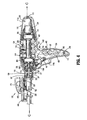
- powered surgical instrument 10 includes a housing 110, an endoscopic portion 140 defining a first longitudinal axis A-A extending therethrough, and an end effector 160, defining a second longitudinal axis B-B extending therethrough.
- Endoscopic portion 140 extends distally from housing 110 and the end effector 160 is disposed adjacent a distal portion of endoscopic portion 140.
- the components of the housing 110 are sealed against infiltration of particulate and/or fluid contamination and help prevent damage of the component by the sterilization process.
- end effector 160 includes a first jaw member having one or more surgical fasteners (e.g., cartridge assembly 164) and a second opposing jaw member including an anvil portion for deploying and forming the surgical fasteners (e.g., an anvil assembly 162).
- the staples are housed in cartridge assembly 164 to apply linear rows of staples to body tissue either in simultaneous or sequential manner.
- Either one or both of the anvil assembly 162 and the cartridge assembly 164 are movable in relation to one another between an open position in which the anvil assembly 162 is spaced from cartridge assembly 164 and an approximated or clamped position in which the anvil assembly 162 is in juxtaposed alignment with cartridge assembly 164.
- end effector 160 is attached to a mounting portion 166, which is pivotably attached to a body portion 168.
- Body portion 168 may be integral with endoscopic portion 140 of powered surgical instrument 10, or may be removably attached to the instrument 10 to provide a replaceable, disposable loading unit (DLU) or single use loading unit (SULU) (e.g., loading unit 169).
- DLU disposable loading unit
- SULU single use loading unit
- the reusable portion may be configured for sterilization and re-use in a subsequent surgical procedure.
- the loading unit 169 may be connectable to endoscopic portion 140 through a bayonet connection. It is envisioned that the loading unit 169 has an articulation link connected to mounting portion 166 of the loading unit 169 and the articulation link is connected to a linkage rod so that the end effector 160 is articulated as the linkage rod is translated in the distal-proximal direction along first longitudinal axis A-A. Other means of connecting end effector 160 to endoscopic portion 140 to allow articulation may be used, such as a flexible tube or a tube comprising a plurality of pivotable members.
- the loading unit 169 may incorporate or be configured to incorporate various end effectors, such as vessel sealing devices, linear stapling devices, circular stapling devices, cutters, etc. Such end effectors may be coupled to endoscopic portion 140 of powered surgical instrument 10.
- the loading unit 169 may include a linear stapling end effector that does not articulate.
- An intermediate flexible shaft may be included between handle portion 112 and loading unit. It is envisioned that the incorporation of a flexible shaft may facilitate access to and/or within certain areas of the body.
- housing 110 includes a handle portion 112 having a main drive switch 114 disposed thereon.
- the switch 114 may include first and second switches 114a and 114b formed together as a toggle switch.
- the handle portion 112, which defines a handle axis H-H, is configured to be grasped by fingers of a user.
- the handle portion 112 has an ergonomic shape providing ample palm grip leverage which helps prevent the handle portion 112 from being squeezed out of the user's hand during operation.
- Each switch 114a and 114b is shown as being disposed at a suitable location on handle portion 112 to facilitate its depression by a user's finger or fingers.
- switches 114a, 114b may be used for starting and/or stopping movement of drive motor 200 ( Fig. 4 ).
- the switch 114a is configured to activate the drive motor 200 in a first direction to advance firing rod 220 ( Fig. 5 ) in a distal direction thereby clamping the anvil and the cartridge assemblies 162 and 164.
- the switch 114b may be configured to retract the firing rod 220 to open the anvil and cartridge assemblies 162 and 164 by activating the drive motor 200 in a reverse direction.
- the retraction mode initiates a mechanical lock out, preventing further progression of stapling and cutting by the loading unit 169.
- the toggle has a first position for activating switch 114a, a second position for activating switch 114b, and a neutral position between the first and second positions.
- the housing 110 in particular the handle portion 112, includes switch shields 117a and 117b.
- the switch shields 117a and 117b may have a rib-like shape surrounding the bottom portion of the switch 114a and the top portion of the switch 114b, respectively.
- the switch shield 117a and 117b prevent accidental activation of the switch 114. Further, the switches 114a and 114b have high tactile feedback requiring increased pressure for activation.
- the switches 114a and 114b are configured as multi-speed (e.g., two or more), incremental or variable speed switches which control the speed of the drive motor 200 and the firing rod 220 in a non-linear manner.
- switches 114a, b can be pressure-sensitive. This type of control interface allows for gradual increase in the rate of speed of the drive components from a slower and more precise mode to a faster operation.
- the switch 114b may be disconnected electronically until a fail safe switch is pressed.
- a third switch 114c may also be used for this purpose.
- the fail safe can be overcome by pressing and holding the switch 114b for a predetermined period of time from about 100 ms to about 2 seconds.
- the firing rod 220 then automatically retracts to its initial position unless the switch 114b is activated (e.g., pressed and released) during the retraction mode to stop the retraction. Subsequent pressing of the switch 114b after the release thereof resumes the retraction. Alternatively, the retraction of the firing rod 220 can continue to full retraction even if the switch 114b is released, in other embodiments.
- the switches 114a and 114b are coupled to a non-linear speed control circuit 115 which can be implemented as a voltage regulation circuit, a variable resistance circuit, or a microelectronic pulse width modulation circuit.
- the switches 114a and 144b may interface with the control circuit 115 by displacing or actuating variable control devices, such as rheostatic devices, multiple position switch circuit, linear and/or rotary variable displacement transducers, linear and/or rotary potentiometers, optical encoders, ferromagnetic sensors, and Hall Effect sensors.
- switches 114a and 114b to operate the drive motor 200 in multiple speed modes, such as gradually increasing the speed of the drive motor 200 either incrementally or gradually depending on the type of the control circuit 115 being used, based on the depression of the switches 114a and 114b.
- the switch 114c may also be included ( Figs. 1 , 2 and 4 ), wherein depression thereof may mechanically and/or electrically change the mode of operation from clamping to firing.
- the switch 114c is recessed within the housing 110 and has high tactile feedback to prevent false actuations. Providing of a separate control switch to initialize the firing mode allows for the jaws of the end effector to be repeatedly opened and closed, so that the instrument 10 is used as a grasper until the switch 114c is pressed, thus activating the stapling and/or cutting.
- the switch 114 may include one or more microelectronic membrane switches, for example.
- Such a microelectronic membrane switch includes a relatively low actuation force, small package size, ergonomic size and shape, low profile, the ability to include molded letters on the switch, symbols, depictions and/or indications, and a low material cost. Additionally, switches 114 (such as microelectronic membrane switches) may be sealed to help facilitate sterilization of the instrument 10, as well as helping to prevent particle and/or fluid contamination.
- other input devices may include voice input technology, which may include hardware and/or software incorporated in a control system 501 ( Fig. 14 ), or a separate digital module connected thereto.
- the voice input technology may include voice recognition, voice activation, voice rectification and/or embedded speech.
- the user may be able to control the operation of the instrument in whole or in part through voice commands, thus freeing one or both of the user's hands for operating other instruments.
- Voice or other audible output may also be used to provide the user with feedback.
- a proximal area 118 of housing 110 having a user interface 120 is shown.
- the user interface 120 includes a screen 122 and a plurality of switches 124.
- the user interface 120 may display various types of operational parameters of the instrument 10 such as "mode” (e.g., rotation, articulation or actuation), which may be communicated to user interface via a sensor, "status” (e.g., angle of articulation, speed of rotation, or type of actuation) and "feedback,” such as whether staples have been fired based on the information reported by the sensors disposed in the instrument 10.
- mode e.g., rotation, articulation or actuation
- status e.g., angle of articulation, speed of rotation, or type of actuation
- feedback such as whether staples have been fired based on the information reported by the sensors disposed in the instrument 10.
- the screen 122 may be an LCD screen, a plasma screen, electroluminescent screen and the like. In one embodiment the screen 122 may be a touch screen, obviating the need for the switches 124.
- the touch screen may incorporate resistive, surface wave, capacitive, infrared, strain gauge, optical, dispersive signal or acoustic pulse recognition touch screen technologies.
- the touch screen may be used to allow the user to provide input while viewing operational feedback. This approach may enable facilitation of sealing screen components to help sterilize the instrument 10, as well as preventing particle and/or fluid contamination.
- screen is pivotably or rotatably mounted to the instrument 10 for flexibility in viewing screen during use or preparation (e.g., via a hinge or ball-and-socket mount).
- the switches 124 may be used for starting and/or stopping movement of the instrument 10 as well as selecting the pivot direction, speed and/or torque. It is also envisioned that at least one switch 124 can be used for selecting an emergency mode that overrides various settings. The switches 124 may also be used for selecting various options on the screen 122, such as responding to prompts while navigating user interface menus and selecting various settings, allowing a user input different tissue types, and various sizes and lengths of staple cartridges.
- the switches 124 may be formed from a micro-electronic tactile or non-tactile membrane, a polyester membrane, elastomer, plastic or metal keys of various shapes and sizes. Additionally, switches may be positioned at different heights from one another and/or may include raised indicia or other textural features (e.g., concavity or convexity) to allow a user to depress an appropriate switch without the need to look at user interface 120.
- switches may be formed from a micro-electronic tactile or non-tactile membrane, a polyester membrane, elastomer, plastic or metal keys of various shapes and sizes. Additionally, switches may be positioned at different heights from one another and/or may include raised indicia or other textural features (e.g., concavity or convexity) to allow a user to depress an appropriate switch without the need to look at user interface 120.
- the user interface 120 may include one or more visual outputs 123 which may include one or more colored visible lights or light emitting diodes ("LED") to relay feedback to the user.
- the visual outputs 123 may include corresponding indicators of various shapes, sizes and colors having numbers and/or text which identify the visual outputs 123.
- the visual outputs 123 are disposed on top of the housing 110 such that the outputs 123 are raised and protrude in relation to the housing 110 providing for better visibility thereof.
- the multiple lights display in a certain combination to illustrate a specific operational mode to the user.
- the visual outputs 123 include a first light (e.g., yellow) 123a, a second light (e.g., green) 123b and a third light (e.g., red) 123c.
- the lights are operated in a particular combination associated with a particular operational mode as listed in Table 1 below.
- Table 1 Light Combination Operational Mode Light Status No loading unit 169 or staple cartridge is loaded.
- First Light Off Second Light Off Third Light Off Light Status The loading unit 169 and/or staple cartridge are loaded and power is activated, allowing the end effector 160 to clamp as a grasper and articulate.
- First Light On Second Light Off Third Light Off Light Status A used loading unit 169 or staple cartridge is loaded.
- First Light Flashing Second Light Off Third Light Off Light Status Instrument 10 is deactivated and prevented from firing staples or cutting.
- First Light N/A Second Light Off Third Light N/A Light Status A new loading unit 169 is loaded, the end effector 160 is fully clamped and the instrument 10 is in firing staple and cutting modes.
- First Light On Second Light On Third Light Off Light Status Due to high stapling forces a pulse mode is in effect, providing for a time delay during which tissue is compressed.
- First Light On Second Light Flashing Third Light Off Light Status No system errors detected.
- First Light N/A Second Light N/A Third Light Off Light Status Tissue thickness and/or firing load is too high, this warning can be overridden.
- First Light On Second Light On Third Light On Light Status Functional system error is detected, instrument 10 should be replaced.
- the visual output 123 may include a single multi-colored LED which display a particular color associated with the operational modes as discussed above with respect to the first, second and third lights in Table 1.
- the user interface 120 also includes audio outputs 125 (e.g., tones, bells, buzzers, integrated speaker, etc.) to communicate various status changes to the user such as lower battery, empty cartridge, etc.
- the audible feedback can be used in conjunction with or in lieu of the visual outputs 123.
- the audible feedback may be provided in the forms of clicks, snaps, beeps, rings and buzzers in single or multiple pulse sequences.
- a simulated mechanical sound may be prerecorded which replicates the click and/or snap sounds generated by mechanical lockouts and mechanisms of conventional non-powered instruments. This eliminates the need to generate such mechanical sounds through the actual components of the instrument 10 and also avoids the use of beeps and other electronic sounds which are usually associated with other operating room equipment, thereby preventing confusion from extraneous audible feedback.
- the instrument 10 may also provide for haptic or vibratory feedback through a haptic mechanism (not explicitly shown) within the housing 110.
- the haptic feedback may be used in conjunction with the auditory and visual feedback or in lieu thereof to avoid confusion with the operating room equipment which relies on audio and visual feedback.
- the haptic mechanism may be an asynchronous motor that vibrates in a pulsating manner. In one embodiment, the vibrations are at a frequency of about 30 Hz or above providing a displacement having an amplitude of 1.5 mm or lower to limit the vibratory effects from reaching the loading unit 169.
- user interface 120 includes different colors and/or intensities of text on screen and/or on switches for further differentiation between the displayed items.
- the visual, auditory or haptic feedback can be increased or decreased in intensity.
- the intensity of the feedback may be used to indicate that the forces on the instrument are becoming excessive.
- Figs. 2-4 illustrate an articulation mechanism 170, including an articulation housing 172, a powered articulation switch 174, an articulation motor 132 and a manual articulation knob 176.
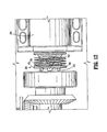
- Translation of the powered articulation switch 174 or pivoting of the manual articulation knob 176 activates the articulation motor 132 which then actuates an articulation gear 233 of the articulation mechanism 170 as shown in Fig. C.
- Actuation of articulation mechanism 170 causes the end effector 160 to move from its first position, where longitudinal axis B-B is substantially aligned with longitudinal axis A-A, towards a position in which longitudinal axis B-B is disposed at an angle to longitudinal axis A-A.
- a plurality of articulated positions is achieved.
- the powered articulation switch 174 may also incorporate similar non-linear speed controls as the clamping mechanism as controlled by the switches 114a and 114b.
- the housing 110 includes switch shields 169 having a wing-like shape and extending from the top surface of the housing 110 over the switch 174.
- the switch shields 169 prevent accidental activation of the switch 174 and require the user to reach below the shield 169 in order to activate the articulation mechanism 170.
- articulation housing 172 and powered articulation switch 174 are mounted to a rotating housing assembly 180. Rotation of a rotation knob 182 about first longitudinal axis A-A causes housing assembly 180 as well as articulation housing 172 and powered articulation switch 174 to rotate about first longitudinal axis A-A, and thus causes corresponding rotation of distal portion 224 of firing rod 220 and end effector 160 about first longitudinal axis A-A.
- the articulation mechanism 170 is electromechanically coupled to first and second conductive rings 157 and 159 which are disposed on the housing nose assembly 155 as shown in Figs. 4 and 26 .
- the conductive rings 157 and 159 may be soldered and/or crimped onto the nose assembly 155 and are in electrical contact with the power source 400 thereby providing electrical power to the articulation mechanism 170.
- the nose assembly 155 may be modular and may be attached to the housing 110 during assembly to allow for easier soldering and/or crimping of the rings.
- the articulation mechanism 170 includes one or more brush and/or spring loaded contacts in contact with the conductive rings 157 and 159 such that as the housing assembly 180 is rotated along with the articulation housing 172 the articulation mechanism 170 is in continuous contact with the conductive rings 157 and 159 thereby receiving electrical power from the power source 400.
- articulation housing 172 powered articulation switch 174, manual articulation knob 176 and providing articulation to end effector 160 are described in detail in commonly-owned U.S. Patent Application Serial No. 11 f724,733 filed March 15, 2007 , the contents of which are hereby incorporated by reference in their entirety. It is envisioned that any combinations of limit switches, proximity sensors (e.g., optical and/or ferromagnetic), linear variable displacement transducers and shaft encoders which may be disposed within housing 110, may be utilized to control and/or record an articulation angle of end effector 160 and/or position of the firing rod 220.
- limit switches e.g., optical and/or ferromagnetic
- linear variable displacement transducers and shaft encoders which may be disposed within housing 110, may be utilized to control and/or record an articulation angle of end effector 160 and/or position of the firing rod 220.
- Figs. 4-8 illustrate various internal components of the instrument 10, including a drive motor 200, a drive tube 210 and a firing rod 220 having a proximal portion 222 and a distal portion 224.
- the drive tube 210 is rotatable about drive tube axis C-C extending therethrough.
- Drive motor 200 is disposed in mechanical cooperation with drive tube 210 and is configured to rotate the drive tube 210 about drive gear axis C-C.
- the drive motor 200 may be an electrical motor or a gear motor, which may include gearing incorporated within its housing.
- the housing 110 may be formed from two halves 110a and 110b as illustrated in Fig. 3 .
- the two housing portion halves 110a and 110b may be attached to each other using screws at boss locators 111 which align the housing portions 110a and 110b.
- the housing 110 may be formed from plastic and may include rubber support members applied to the internal surface of the housing 110 via a two-shot molding process. The rubber support members may isolate the vibration of the drive components (e.g., drive motor 200) form the rest of the instrument 10.
- the housing halves 110a and 110b may be attached to each via a thin section of plastic (e.g., a living hinge) that interconnects the halves 110a and 110b allowing the housing 110 to be opened by breaking away the halves 110a and 110b.
- a thin section of plastic e.g., a living hinge
- the drive components may be mounted on a support plate allowing the drive components to be removed from the housing 110 after the instrument 10 has been used.
- the support plate mounting in conjunction with the hinged housing halves 110a and 110b provide for reusability and recyclability of specific internal components while limiting contamination thereof.
- Firing rod coupling 190 provides a link between the proximal portion 222 and the distal portion 224 of the firing rod 220. Specifically, the firing rod coupling 190 enables rotation of the distal portion 224 of the firing rod 220 with respect to proximal portion 222 of firing rod 220. Thus, firing rod coupling 190 enables proximal portion 222 of firing rod 220 to remain non-rotatable, as discussed below with reference to an alignment plate 350, while allowing rotation of distal portion 224 of firing rod 220 (e.g., upon rotation of rotation knob 182).
- the proximal portion 222 of firing rod 220 includes a threaded portion 226, which extends through an internally-threaded portion 212 of drive tube 210.
- This relationship between firing rod 220 and drive tube 210 causes firing rod 220 to move distally and/or proximally, in the directions of arrows D and E, along threaded portion 212 of drive tube 210 upon rotation of drive tube 210 in response to the rotation of the drive motor 200.
- a first direction e.g., clockwise
- firing rod 220 moves proximally as illustrated in Fig. 5
- the firing rod 220 is disposed at its proximal-most position.
- As the drive tube 210 rotates in a second direction e.g., counter-clockwise
- firing rod 220 moves distally as illustrated in Fig. 6
- the firing rod 220 is disposed at its distal-most position.
- the firing rod 220 is distally and proximally translatable within particular limits. Specifically, a first end 222a of proximal portion 222 of firing rod 220 acts as a mechanical stop in combination with an alignment plate 350. That is, upon retraction when firing rod 220 is translated proximally, first end 222a contacts a distal surface 351 of alignment plate 350, thus preventing continued proximal translation of firing rod 220 as shown in Fig. 5 . Additionally, threaded portion 226 of the proximal portion 222 acts as a mechanical stop in combination with alignment plate 350.
- the alignment plate 350 includes an aperture therethrough, which has a non-round cross-section.
- the non-round cross-section of the aperture prevents rotation of proximal portion 222 of firing rod 220, thus limiting proximal portion 222 of firing rod 220 to axial translation therethrough.
- a proximal bearing 354 and a distal bearing 356 are disposed at least partially around drive tube 210 for facilitation of rotation of drive tube 210, while helping align drive tube 210 within housing 110.
- Rotation of drive tube 210 in a first direction corresponds with distal translation of the firing rod 220 which actuates jaw members 162, 164 of the end effector 160 to grasp or clamp tissue held therebetween. Additional distal translation of firing rod 220 ejects surgical fasteners from the end effector 160 to fasten tissue by actuating cam bars and/or an actuation sled 74 ( Fig. 9 ). Further, the firing rod 220 may also be configured to actuate a knife (not explicitly shown) to sever tissue.
- Proximal translation of firing rod 220 corresponding with rotation of the drive tube 210 in a second direction actuates jaw members 162, 164 and/or knife to retract or return to corresponding pre-fired positions.
- a second direction e.g., clockwise
- firing and otherwise actuating end effector 160 are described in detail in commonly-owned U.S. Patent No. 6,953,139 to Milliman et al. (the '139 Milliman patent), the disclosure of which is hereby incorporated by reference herein.
- Fig. X shows an exploded view of the loading unit 169.
- the end effector 160 may be actuated by an axial drive assembly 213 having a drive beam or drive member 266.
- the distal end of the drive beam 213 may include a knife blade.
- the drive beam 213 includes a retention flange 40 having a pair of cam members 40a which engage the anvil and the cartridge assembly 162 and 164 during advancement of the drive beam 213 longitudinally.
- the drive beam 213 advances an actuation sled 74 longitudinally through the staple cartridge 164.
- the sled 74 has cam wedges for engaging pushers 68 disposed in slots of the cartridge assembly 164, as the sled 74 is advanced. Staples 66 disposed in the slots are driven through tissue and against the anvil assembly 162 by the pushers 66.
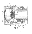
- a drive motor shaft 202 is shown extending from a planetary gear 204 that is attached to drive motor 200.
- Drive motor shaft 202 is in mechanical cooperation with clutch 300.
- Drive motor shaft 202 is rotated by the drive motor 200, thus resulting in rotation of clutch 300.
- Clutch 300 includes a clutch plate 302 and a spring 304 and is shown having wedged portions 306 disposed on clutch plate 302, which are configured to mate with an interface (e.g., wedges 214) disposed on a proximal face 216 of drive tube 210.
- Spring 304 is illustrated between planetary gear 204 and drive tube 210. Specifically, and in accordance with the embodiment illustrated in Fig. 8 , spring 304 is illustrated between clutch face 302 and a clutch washer 308. Additionally, drive motor 200 and planetary gear 204 are mounted on a motor mount 310. As illustrated in Fig. 8 , motor mount 310 is adjustable proximally and distally with respect to housing 110 via slots 312 disposed in motor mount 310 and protrusions 314 disposed on housing 110.
- the clutch 300 is implemented as a slip unidirectional clutch to limit torque and high inertia loads on the drive components.
- Wedged portions 306 of clutch 300 are configured and arranged to slip with respect to wedges 214 of proximal face 216 of drive tube 210 unless a threshold force is applied to clutch plate 302 via clutch spring 304. Further, when spring 304 applies the threshold force needed for wedged portions 306 and wedges 214 to engage without slipping, drive tube 210 will rotate upon rotation of drive motor 200. It is envisioned that wedged portions 306 and/or wedges 214 are configured to slip in one and/or both directions (i.e., clockwise and/or counter-clockwise) with respect to one another until a threshold force is attained.
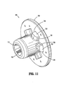
- the clutch 300 is shown with a unidirectional clutch plate 700.
- the clutch plate 700 includes a plurality of wedged portions 702 having a slip face 704 and a grip face 706.
- the slip face 704 has a curved edge which engages the wedges 214 of the drive tube 210 up to a predetermined load.
- the grip face 706 has a flat edge which fully engages the drive tube 210 and prevents slippage.
- a first direction e.g., clockwise
- the grip face 706 of the wedged portions 702 engage the wedges 214 without slipping, providing for full torque from the drive motor 200.
- the clutch plate 700 When the clutch plate 700 is rotated in a reverse direction (e.g., counterclockwise) the slip face 704 of the wedged portions 702 engage the wedges 214 and limit the torque being transferred to the drive tube 210. Thus, if the load being applied to the slip face 704 is over the limit, the clutch 300 slips and the drive tube 210 is not rotated. This prevents high load damage to the end effector 160 or tissue which can occur due to the momentum and dynamic friction of the drive components. More specifically, the drive mechanism of the instrument 10 can drive the drive rod 220 in a forward direction with less torque than in reverse. Use of a unidirectional clutch eliminates this problem. In addition electronic clutch may also be used to increase the motor potential during retraction (e.g., driving the drive rod 220 in reverse) as discussed in more detail below.
- drive motor shaft 202 includes a D-shaped cross-section 708, which includes a substantially flat portion 710 and a rounded portion 712.
- drive motor shaft 202 will not “slip” with respect to clutch plate 302 upon rotation of drive motor shaft 202. That is, rotation of drive motor shaft 202 will result in a slip-less rotation of clutch plate 302.
- the loading unit in certain embodiments according to the present disclosure, includes an axial drive assembly that cooperates with firing rod 220 to approximate anvil assembly 1fi2 and cartridge assembly 164 of end effector 160, and fire staples from the staple cartridge.
- the axial drive assembly may include a beam that travels distally through the staple cartridge and may be retracted after the staples have been fired, as discussed above and as disclosed in certain embodiments of the ⁇ 139 Milliman patent.
- the instrument 10 includes a power source 400 which may be a rechargeable battery (e.g., lead-based, nickel-based, lithium-ion based, etc.). It is also envisioned that the power source 400 includes at least one disposable battery. The disposable battery may be between about 9 volts and about 30 volts.
- the power source 400 includes one or more battery cells 401 depending on the current load needs of the instrument 10. Further, the power source 400 includes one or more ultracapacitors 402 which act as supplemental power storage due to their much higher energy density than conventional capacitors. Ultracapacitors 402 can be used in conjunction with the cells 401 during high energy draw. The ultracapacitors 402 can be used for a burst of power when energy is desired/required more quickly than can be provided solely by the cells 401(e.g., when clamping thick tissue, rapid firing, clamping, etc.), as cells 401 are typically slow-drain devices from which current cannot be quickly drawn. This configuration can reduce the current load on the cells thereby reducing the number of cells 401. It is envisioned that cells 401 can be connected to the ultracapacitors 402 to charge the capacitors.
- the power source 400 may be removable along with the drive motor 200 to provide for recycling of theses components and reuse of the instrument 10.
- the power source 400 may be an external battery pack which is worn on a belt and/or harness by the user and wired to the instrument 10 during use.
- the power source 400 is enclosed within an insulating shield 404 which may be formed from an absorbent, flame resistant and retardant material.
- the shield 404 prevents heat generated by the power source 400 from heating other components of the instrument 10.
- the shield 404 may also be configured to absorb any chemicals or fluids which may leak from the cells 402 during heavy use and/or damage.
- the power source 400 is coupled to a power adapter 406 which is configured to connect to an external power source (e.g., DC transformer).
- the external power source may be used to recharge the power source 400 or provide for additional power requirements.
- the power adapter 406 may also be configured to interface with electrosurgical generators which can then supply power to the instrument 10.
- the instrument 10 also includes an AC-to-DC power source which converts RF energy from the electrosurgical generators and powers the instrument 10.
- the power source 400 is recharged using an inductive charging interface.
- the power source 400 is coupled to an inductive coil (not explicitly shown) disposed within the proximal portion of the housing 110.
- the inductive coil Upon being placed within an electromagnetic field, the inductive coil converts the energy into electrical current that is then used to charge the power source 400.
- the electromagnetic field may be produced by a base station (not explicitly shown) which is configured to interface with the proximal portion of the housing 110, such that the inductive coil is enveloped by the electromagnetic field. This configuration eliminates the need for external contacts and allows for the proximal portion of the housing 110 to seal the power source 400 and the inductive coil within a water-proof environment which prevents exposure to fluids and contamination.
- the instrument 10 also includes one or more safety circuits such as a discharge circuit 410 and a motor and battery operating module 412.
- a discharge circuit 410 for clarity, wires and other circuit elements interconnecting various electronic components of the instrument 10 are not shown, but such electromechanical connections wires are contemplated by the present disclosure. Certain components of the instrument 10 communicate wirelessly.
- the discharge circuit 410 is coupled to a switch 414 and a resistive load 417 which are in turn coupled to the power source 400.
- the switch 414 may be a user activated or an automatic (e.g., timer, counter) switch which is activated when the power source 400 needs to be fully discharged for a safe and low temperature disposal (e.g., at the end of surgical procedure).
- the load 417 is electrically connected to the power source 400 such that the potential of the power source 400 is directed to the load 417.
- the automatic switch may be a timer or a counter which is automatically activated after a predetermined operational time period or number of uses to discharge the power source 400.
- the load 417 has a predetermined resistance sufficient to fully and safely discharge all of the cells 401.
- the motor and battery operating module 412 is coupled to one or more thermal sensors 413 which determine the temperature within the drive motor 200 and the power source 400 to ensure safe operation of the instrument 10.
- the sensors may be an ammeter for determining the current draw within the power source 400, a thermistor, a thermopile, a thermocouple, a thermal infrared sensor and the like. Monitoring temperature of these components allows for a determination of the load being placed thereon. The increase in the current flowing through these components causes an increase in temperature therein. The temperature and/or current draw data may then be used to control the power consumption in an efficient manner or assure safe levels of operation.
- the power source 400 is authentic and/or valid (e.g., conforms to strict quality and safety standards) and operating within a predetermined temperature range. Authentication that the power source 400 is valid minimizes risk of injury to the patient and/or the user due to poor quality.
- the power source 400 is shown having one or more battery cells 401, a temperature sensor 403 and an embedded microcontroller 405 coupled thereto.
- the microcontroller 405 is coupled through wired and/or wireless communication protocols to microcontroller 500 ( Fig. 14 ) of the instrument 10 to authenticate the power source 400.
- the temperature sensor 403 can be coupled directly to the microcontroller 500 instead of being coupled to the embedded microcontroller 405.
- the temperature sensor 403 may be a thermistor, a thermopile, a thermocouple, a thermal infrared sensor, a resistance temperature detector, linear active thermistor, temperature-responsive color changing strips, bimetallic contact switches, and the like.
- the temperature sensor 403 reports the measured temperature to the microcontroller 405 and/or microcontroller 500.
- the embedded microcontroller 405 executes a so-called challenge-response authentication algorithm with the microcontroller 500 which is illustrated in Fig. 10 .
- the power source 400 is connected to the instrument 10 and the instrument 10 is switched on.
- the microcontroller 500 sends a challenge request to the embedded microcontroller 405.
- the microcontroller 405 interprets the challenge request and generates a response as a reply to the request.
- the response may include an identifier, such as a unique serial number stored in a radio frequency identification tag or in memory of the microcontroller 405, a unique electrical measurable value of the power source 400 (e.g., resistance, capacitance, inductance, etc.).
- the response includes the temperature measured by the temperature sensor 403.
- step 634 the microcontroller 500 decodes the response to obtain the identifier and the measured temperature.
- step 636 the microcontroller 500 determines if the power source 400 is authentic based on the identifier, by comparing the identifier against a pre-approved list of authentic identifiers. If the identifier is not valid, the instrument 10 is not going to operate and displays a "failure to authenticate battery" message via the user interface 120. If the identifier is valid, the process proceeds to step 640 where the measured temperature is analyzed to determine if the measurement is within a predetermined operating range. If the temperature is outside the limit, the instrument 10 also displays the failure message. Thus, if the temperature is within the predetermined limit and the identifier is valid, in step 642, the instrument commences operation, which may include providing a "battery authenticated" message to the user.
- a plurality of sensors for providing feedback information relating to the function of the instrument 10 are illustrated. Any combination of sensors may be disposed within the instrument 10 to determine its operating stage, such as, staple cartridge load detection as well as status thereof, articulation, clamping, rotation, stapling, cutting and retracting, and the like.
- the sensors can be actuated by proximity, displacement or contact of various internal components of the instrument 10 (e.g., firing rod 220, drive motor 200, etc.).
- the sensors can be rheostats (e.g., variable resistance devices), current monitors, conductive sensors, capacitive sensors, inductive sensors, thermal-based sensors, limit actuated switches, multiple position switch circuits, pressure transducers, linear and/or rotary variable displacement transducers, linear and/or rotary potentiometers, optical encoders, ferromagnetic sensors, Hall Effect sensors, and proximity switches.
- the sensors measure rotation, velocity, acceleration, deceleration, linear and/or angular displacement, detection of mechanical limits (e.g., stops), etc. This is attained by implementing multiple indicators arranged in either linear or rotational arrays on the mechanical drive components of the instrument 10.
- the sensors then transmit the measurements to the microcontroller 500 which determines the operating status of the instrument 10.
- the microcontroller 500 also adjusts the motor speed or torque of the instrument 10 based on the measured feedback.
- linear displacement sensors e.g., linear displacement sensor 237) are positioned distally of the clutch 300 to provide accurate measurements. In this configuration, slippage of the clutch 300 does not affect the position, velocity and acceleration measurements recorded by the sensors.
- a load switch 230 is disposed within the articulation housing 172.
- the switch 230 is connected in series with the switch 114, preventing activation of the instrument 10 unless the loading unit 169 is properly loaded into the instrument 10. If the loading unit 169 is not loaded into the instrument 10, the main power switch (e.g., switch 114) is open, thereby preventing use of any electronic or electric components of the instrument 10. This also prevents any possible current draw from the power source 400 allowing the power source 400 to maintain a maximum potential over its specified shelf life.
- the switch 230 acts as a so-called "lock-out” switch which prevents false activation of the instrument 10 since the switch is inaccessible to external manipulation and can only be activated by the insertion of the loading unit 169.
- the switch 230 is activated by displacement of a plunger or sensor tube as the loading unit 169 is inserted into the endoscopic portion 140.
- the power from the power source 400 is supplied to the electronic components (e.g., sensors, microcontroller 500, etc.) of the instrument 10 providing the user with access to the user interface 120 and other inputs/outputs. This also activates the visual outputs 123 to light up according to the light combination indicative of a properly loaded loading unit 169 wherein all the lights are off as described in Table 1.
- the endoscopic portion 140 includes a sensor plate 360 therein which is in mechanical contact with a sensor tube also disposed within the endoscopic portion 140 and around the distal portion 224 of firing rod 220.
- the distal portion 224 of the firing rod 220 passes through an opening 368 at a distal end of a sensor cap 364.
- the sensor cap 364 includes a spring and abuts the switch 230. This allows the sensor cap 364 to be biased against the sensor tube 362 which rests on the distal end of the sensor cap 364 without passing through the opening 368. Biasing of the sensor tube 362 then pushes out the sensor plate 360 accordingly.
- the proximal portion 171 When the loading unit 169 is loaded into the endoscopic portion 140, the proximal portion 171 abuts the sensor plate 360 and displaces the plate 360 in a proximal direction. The sensor plate 360 then pushes the sensor tube 362 in the proximal direction which then applies pressure on the sensor cap 364 thereby compressing the spring 366 and activating the switch 230 denoting that the loading unit 169 has been properly inserted.
- the switch 230 determines whether the loading unit 169 is loaded correctly based on the position thereof. If the loading unit 169 is improperly loaded, the switch 114 is not activated and an error code is relayed to the user via the user interface 120 (e.g., all the lights are off as described in Table 1). If the loading unit 169 has already been fired, any mechanical lockouts have been previously activated or the staple cartridge has been used, the instrument 10 relays the error via the user interface 120, e.g., the first light 123a is flashing.
- a second lock-out switch 259 coupled to the main switch 114 may be implemented in the instrument 10 as a bioimpedance, capacitance or pressure sensor disposed on the top surface of the handle portion 112 configured to be activated when the user grasps the instrument 10. Thus, unless the instrument 10 is grasped properly, the operation of the switch 114 is disabled.
- the instrument 10 includes a position calculator 416 for determining and outputting current linear position of the firing rod 220.
- the position calculator 416 is electrically connected to a linear displacement sensor 237 and a rotation speed detecting apparatus 418 is coupled to the drive motor 200.
- the apparatus 418 includes an encoder 420 coupled to the motor for producing two or more encoder pulse signals in response to the rotation of the drive motor 200.
- the encoder 420 transmits the pulse signals to the apparatus 418 which then determines the rotational speed of the drive motor 200.
- the position calculator 416 thereafter determines the linear speed and position of the firing rod based on the rotational speed of the drive motor 200 since the rotation speed is directly proportional to the linear speed of the firing rod 220.
- the position calculator 416 and the speed calculator 422 are coupled to the microcontroller 500 which controls the drive motor 200 in response to the sensed feedback form the calculators 416 and 422. This configuration is discussed in more detail below with respect to Fig. 14 .
- the instrument 10 includes first and second indicators 320a, 320b disposed on the firing rod 220, which determine the speed of firing rod 220 and the location of firing rod 220 with respect to drive tube 210 and/or housing 110.
- a limit switch may be activated (e.g., shaft start position sensor 231 and clamp position sensor 232) by sensing first and second indicators 320a and/or 320b (e.g., bumps, grooves, indentations, etc.) passing thereby to determine position of firing rod 220, speed of firing rod 220 and mode of the instrument 10 (e.g., clamping, grasping, firing, sealing, cutting, retracting).
- the feedback received from first and second indicators 320a, 320b may be used to determine when firing rod 220 should stop its axial movement (e.g., when drive motor 200 should cease) depending on the size of the particular loading unit attached thereto.
- the first actuation of the position sensor 231 is activated by the first indicator 320a which denotes that operation of the instrument 10 has commenced.
- the firing rod 220 is moved further distally to initiate clamping, which moves first indicator 320a to interface with clamp position sensor 232. Further advancement of the firing rod 220 moves the second indicator 320b to interface with the position sensor 232 which indicates that the instrument 10 has been fired.
- the position calculator 416 is coupled to a linear displacement sensor 237 disposed adjacent to the firing rod 220.
- the linear displacement sensor 237 may be a magnetic sensor.
- the firing rod 220 may be magnetized or may include magnetic material therein.
- the magnetic sensor may be a ferromagnetic sensor or a Hall Effect sensor which is configured to detect changes in a magnetic field.
- the magnetic sensor transmits data relating to the changes in the magnetic field to the position calculator 416 which then determines the position of the firing rod 220 as a function of the magnetic field data.
- a select portion of the firing rod 220 may be magnetized, such as the threads of the internally-threaded portion 212 or other notches (e.g., indicators 320a and/or 320b) disposed on the firing rod 220 may include or be made from a magnetic material. This allows for correlation of the cyclical variations in the magnetic field with each discrete translation of the threads as the magnetized portions of the firing rod 220 are linearly translated.
- the position calculator 416 thereafter determines the distance and the position of the firing rod 220 by summing the number of cyclical changes in the magnetic field and multiplies the sum by a predetermined distance between the threads and/or notches.
- the linear displacement sensor 237 may be a potentiometer or a rheostat.
- the firing rod 220 includes a contact (e.g., wiper terminal) disposed in electromechanical contact with the linear displacement sensor 237.
- the contact slides along the surface of the linear displacement sensor 237 as the firing rod 220 is moved in the distal direction by the drive motor 200.
- the voltage of the potentiometer and the resistance of the rheostat vary accordingly.
- the variation in voltage and resistance is transmitted to the position calculator 416 which then extrapolates the distance traveled by the firing rod 220 and/or the firing rod coupling 190 and the position thereof.
- the position calculator 416 is coupled to one or more switches 421 which are actuated by the threads of the internally-threaded portion 212 or the indicators 320a and/or 320b as the firing rod 220 and the firing rod coupling 190 are moved in the distal direction.
- the position calculator 416 counts the number of threads which activated the switch 421 and then multiplies the number by a predetermined distance between the threads or the indicators 320a and/or 320b.
- the instrument 10 also includes a speed calculator 422 which determines the current speed of a linearly moving firing rod 220 and/or the torque being provided by the drive motor 200.
- the speed calculator 422 is connected to the linear displacement sensor 237 which allows the speed calculator 422 to determine the speed of the firing rod 220 based on the rate of change of the displacement thereof.
- the speed calculator 422 is coupled to the rotation speed detecting apparatus 424 which includes the encoder 426.
- the encoder 426 transmits the pulses correlating to the rotation of the drive motor 200 which the speed calculator 422 then uses to calculate the linear speed of the firing rod 220.
- the speed calculator 422 is coupled to a rotational sensor 239 which detects the rotation of the drive tube 210, thus, measuring the rate of rotation of the drive tube 210 which allows for determination of the linear velocity of the firing rod 220.
- the speed calculator 422 is also coupled to a voltage sensor 428 which measures the back electromotive force ("EMF") induced in the drive motor 200.
- EMF back electromotive force
- the back EMF voltage of the drive motor 200 is directly proportional to the rotational speed of the drive motor 200 which, as discussed above, is used to determine the linear speed of the firing rod 220.
- Monitoring of the speed of the drive motor 200 can also be accomplished by measuring the voltage across the terminals thereof under constant current conditions. An increase in a load of the drive motor 200 yields a decrease in the voltage applied at the motor terminals, which is directly related to the decrease in the speed of the motor. Thus, measuring the voltage across the drive motor 200 provides for determining the load being placed thereon. In addition, by monitoring the change of the voltage over time (dV/dt), the microprocessor 500 can detect a quick drop in voltage which correlates to a large change in the load or an increase in temperature of the drive motor 200 and/or the power source 400.
- the speed calculator 422 is coupled to a current sensor 430 (e.g., an ammeter).
- the current sensor 430 is in electrical communication with a shunt resistor 432 which is coupled to the drive motor 200.
- the current sensor 430 measures the current being drawn by the drive motor 200 by measuring the voltage drop across the resistor 432. Since the current used to power the drive motor 200 is proportional to the rotational speed of the drive motor 200 and, hence, the linear speed of the firing rod 220, the speed calculator 422 determines the speed of the firing rod 220 based on the current draw of the drive motor 200.
- the speed calculator 422 may also be coupled to a second voltage sensor (not explicitly shown) for determining the voltage within the power source 400 thereby calculating the power draw directly from the source.
- a second voltage sensor (not explicitly shown) for determining the voltage within the power source 400 thereby calculating the power draw directly from the source.
- the change in current over time (dl/dt) can be monitored to detect quick spikes in the measurements which correspond to a large increase in applied torque by the drive motor 200.
- the current sensor 430 is used to determine the speed and the load of the drive motor 200.
- the velocity of the firing rod 220 as measured by the speed calculator 422 may be then compared to the current draw of the drive motor 200 to determine whether the drive motor 200 is operating properly. Namely, if the current draw is not commensurate (e.g., large) with the velocity (e.g., low) of the firing rod 220 then the motor 200 is malfunctioning (e.g., locked, stalled, etc.). If a stall situation is detected, or the current draw exceeds predetermined limits, the position calculator 416 then determines whether the firing rod 220 is at a mechanical stop. If this is the case, then the microcontroller 500 can shut down the drive motor 200 or enters a pulse and/or pause mode (e.g., discontinuous supply of power to the drive motor 200) to unlock the instrument 10 and retract the firing rod 220.
- a pulse and/or pause mode e.g., discontinuous supply of power to the drive motor 200
- the speed calculator 422 compares the rotation speed of the drive tube 210 as detected by the rotation sensor 239 and that of the drive motor 200 based on the measurements from and the rotation speed detecting apparatus 424. This comparison allows the speed calculator 422 to determine whether there is clutch activation problem (e.g., slippage) if there is a discrepancy between the rotation of the clutch 300 and that of the drive tube 210. If slippage is detected, the position calculator 416 then determines whether the firing rod 220 is at a mechanical stop. If this is the case, then the microcontroller 500 can shut down the instrument 10 or enter a pulse and/or pause mode (e.g., discontinuous supply of power to the drive motor 200), or retract the firing rod 220.
- clutch activation problem e.g., slippage
- the instrument 10 also includes sensors adapted to detect articulation of the end effector 160.
- the instrument 10 includes a rotation sensor 241 adapted to indicate the start position, the rotational direction and the angular displacement of the rotating housing assembly 180 at the start of the procedure as detected by the shaft start position sensor 231.
- the rotation sensor 241 operates by counting the number of indicators disposed on the inner surface of the rotation knob 182 by which the rotation knob 182 has been rotated. The count is then transmitted to the microcontroller 500 which then determines the rotational position of the endoscopic portion 142. This can be communicated wirelessly or through an electrical connection on the endoscopic portion and wires to the microcontroller 500.
- the instrument 10 also includes an articulation sensor 235 which determines articulation of the end effector 160.
- the articulation sensor 235 counts the number of 263 disposed on the articulation gear 233 by which the articulation knob 176 has been rotated from its 0° position, namely the center position of the articulation knob 176 and, hence, of the end effector 160 as shown in Fig. C.
- the 0° position and can be designated by a central unique indicator 265 also disposed on the articulation gear 233 which corresponds with the first position of the end effector 160, where longitudinal axis B-B is substantially aligned with longitudinal axis A-A.
- the count is then transmitted to the microcontroller 500 which then determines the articulation position of the end effector 160 and reports the articulation angle via the interface 120.
- the articulation angle can be used for the so-called "auto stop” mode.
- the instrument 10 automatically stops the articulation of the end effector 160 when the end effector 160 is at its central first position. Namely, as the end effector 160 is articulated from a position in which longitudinal axis B-B is disposed at an angle to longitudinal axis A-A towards the first position, the articulation is stopped when the longitudinal axis B-B is substantially aligned with longitudinal axis A-A. This position is detected by the articulation sensor 235 based on the central indicator. This mode allows the endoscopic portion 140 to be extracted without the user having to manually align the end effector 160.
- the present disclosure provides a loading unit identification system 440 which allows the instrument 10 to identify the loading unit 169 and to determine operational status thereof.
- the identification system 440 provides information to the instrument 10 on staple size, cartridge length, type of the loading unit 169, status of cartridge, proper engagement, and the like. This information allows the instrument to adjust clamping forces, speed of clamping and firing and end of stroke for various length staple cartridges.
- the loading unit identification system 440 may also be adapted to determine and communicate to the instrument 10 (e.g., a control system 501 shown in Fig. 14 ) various information, including the speed, power, torque, clamping, travel length and strength limitations for operating the particular end effector 160.
- the control system 501 may also determine the operational mode and adjust the voltage, clutch spring loading and stop points for travel of the components.
- the identification system may include a component (e.g., a microchip, emitter or transmitter) disposed in the end effector 160 that communicates (e.g., wirelessly, via infrared signals, etc.) with the control system 501, or a receiver therein.
- a signal may be spent via firing rod 220, such that firing rod 220 functions as a conduit for communications between the control system 501 and end effector 160.
- the signals can be sent through an intermediate interface, such as a feedback controller 603 ( Figs. 15-17 ).
- the sensors discussed above may be used to determine if the staples have been fired from the staple cartridge, whether they have been fully fired, whether and the extent to which the beam has been retracted proximally through the staple cartridge and other information regarding the operation of the loading unit.
- the loading unit incorporates components for identifying the type of loading unit, and/or staple cartridge loaded on the instrument 10, including infra red, cellular, or radio frequency identification chips.
- the type of loading unit and/or staple cartridge may be received by an associated receiver within the control system 501, or an external device in the operating room for providing feedback, control and/or inventory analysis.
- Information can be transmitted to the instrument 10 via a variety of communication protocols (e.g., wired or wireless) between the loading unit 169 and the instrument 10.
- the information can be stored within the loading unit 169 in a microcontroller, microprocessor, non-volatile memory, radio frequency identification tags, and identifiers of various types such as optical, color, displacement, magnetic, electrical, binary and gray coding (e.g., conductance, resistance, capacitance, impedance).
- the loading unit 169 and the instrument 10 include corresponding wireless transceivers, an identifier 442 and an interrogator 444 respectively.
- the identifier 442 includes memory or may be coupled to a microcontroller for storing various identification and status information regarding the loading unit 169.
- the instrument 10 interrogates the identifier 442 via the interrogator 444 for an identifying code.
- the identifier 442 replies with the identifying code corresponding to the loading unit 169.
- the identifier 442 is configured to provide the instrument 10 with updates as to the status of the loading unit 169 (e.g., mechanical and/or electrical malfunction, position, articulation, etc.).
- the identifier 442 and the interrogator 444 are configured to communicate with each other using one or more of the following communication protocols such as Bluetooth®, ANT3®, KNX®, ZWave®, X10® Wireless USB®, IrDA®, Nanonet®, Tiny OS®, ZigBee®, 802.11 IEEE, and other radio, infrared, UHF, VHF communications and the like.
- the transceiver 400 may be a radio frequency identification (RFID) tag either active or passive, depending on the interrogator capabilities of the transceiver 402.
- RFID radio frequency identification
- Figs. 11A and B illustrate additional embodiments of the loading unit 169 having various types of identification devices.
- a proximal end 171 of the loading unit 169 having an electrical identifier 173 is shown.
- the identifier 173 may include one or more resistors, capacitors, inductors and is coupled with a corresponding electrical contact 181 disposed on the distal end of the endoscopic portion 140.
- the contact may include slip rings, brushes and/or fixed contacts disposed in the endoscopic portion.
- the identifier 173 may be disposed on any location of the loading unit 168 and may be formed on a flexible or fixed circuit or may be traced directly on the surface of the loading unit 169.
- the interrogator contact When the loading unit 169 is coupled with the endoscopic portion 140, the contact applies a small current through the electrical identifier 173.
- the interrogator contact also includes a corresponding electrical sensor which measures the resistance, impedance, capacitance, and/or impedance of the identifier 173.
- the identifier 173 has a unique electrical property (e.g., resistance, capacitance, inductance, etc.) which corresponds to the identifying code of the loading unit 169, thus, when the electrical property thereof is determined, the instrument 10 determines the identity of the loading unit 169 based on the measured property.
- the identifier 173 may be a magnetic identifier such as gray coded magnets and/or ferrous nodes incorporating predetermined unique magnetic patterns identifying the loading unit 169 by the identifying code.
- the magnetic identifier is read via a magnetic sensor (e.g., ferromagnetic sensor, Hall Effect sensor, etc.) disposed at the distal end of the endoscopic portion 140.
- the magnetic sensor transmits the magnetic data to the instrument 10 which then determines the identity of the loading unit 169.
- Fig. 11B illustrates the proximal end 171 of the loading unit 169 having one or more protrusions 175.
- the protrusions 175 can be of any shape, such as divots, bumps, strips, etc., of various dimensions.
- the protrusions 175 interface with corresponding displacement sensors 183 disposed within the proximal segment of the endoscopic portion 140. The sensors are displaced when the protrusions 175 are inserted into the endoscopic portion. The amount of the displacement is analyzed by the sensors and converted into identification data, allowing the instrument 10 to determine staple size, cartridge length, type of the loading unit 169, proper engagement, and the like.
- the displacement sensors can be switches, contacts, magnetic sensors, optical sensors, variable resistors, linear and rotary variable displacement transducers which can be spring loaded.
- the switches are configured to transmit binary code to the instrument 10 based on their activation status. More specifically, some protrusions 175 extend a distance sufficient to selectively activate some of the switches, thereby generating a unique code based on the combination of the protrusions 175.
- the protrusion 175 can be color coded.
- the displacement sensors 183 include a color sensor configured to determine the color of the protrusion 175 to measure one or more properties of the loading unit 169 based on the color and transmits the information to the instrument 10.
- Fig. 12 shows a method for identifying the loading unit 169 and providing status information concerning the loading unit 169 to the instrument 10.
- step 650 it is determined whether the loading unit 169 is properly loaded into the instrument 10. This may be determined by detecting whether contact has been made with the identifier 173 and/or protrusions 175. If the loading unit 169 is properly loaded, in step 652, the loading unit 169 communicates to the instrument 10 a ready status (e.g., turning on the first light of the visual outputs 123).
- the instrument 10 verifies whether the loading unit 169 has been previously fired.
- the identifier 442 stores a value indicative of the previously fired status. If the loading unit 169 was fired, in step 656, the instrument 10 provides an error response (e.g., flashing the first light of the visual outputs 123). If the loading unit 169 has not been fired, in step 658 the loading unit 169 provides identification and status information (e.g., first light is turned on) to the instrument 10 via the identification system 440. The determination whether the loading unit 169 has been fired is made based on the saved "previously fired" signal saved in the memory of the identifier 442 as discussed in more detail below with respect to step 664. In step 660, the instrument 10 adjusts its operating parameters in response to the information received from the loading unit 169.
- step 662 The user performs a surgical procedure via the instrument 10 in step 662. Once the procedure is complete and the loading unit 169 has been fired, the instrument 10 transmits a "previously fired” signal to the loading unit 169. In step 664, the loading unit 169 saves the "previously fired” signal in the memory of the identifier 442 for future interrogations by the instrument 10 as discussed with respect to step 654.
- the loading unit 169 includes one or more tissue sensors disposed within the end effector 160 for detecting the type of object being grasped, such recognizing non-tissue objects and the tissue type of the object.
- the sensors are also configured to determine amount of blood flow being passed between the jaw members of the end effector 160. More specifically, a first tissue sensor 177 is disposed at a distal portion of the anvil assembly 162 and a second tissue sensor 179 is disposed at a distal portion of the cartridge assembly 164.
- the sensors 177 and 179 are coupled to the identifier 442 allowing for transmission of sensor data to the microcontroller 500 of the instrument 10.
- the sensors 177 and 179 are adapted to generate a field and/or waves in one or more arrays or frequencies therebetween.
- the sensors 177 and 179 may be acoustic, ultrasonic, ferromagnetic, Hall Effect sensors, laser, infrared, radio frequency, or piezoelectric devices.
- the sensors 177 and 179 are calibrated for ignoring commonly occurring material, such as air, bodily fluids and various types of human tissue and for detecting certain types of foreign matter.
- the foreign matter may be bone, tendons, cartilage, nerves, major arteries and non-tissue matter, such as ceramic, metal, plastic, etc.
- the sensors 177 and 179 detect the foreign passing between the anvil and cartridge assemblies 162 and 164 based on the absorption, reflection and/or filtering of the field signals generated by the sensors. If the material reduces or reflects a signal, such that the material is outside the calibration range and is, therefore, foreign, the sensors 177 and 179 transmit the interference information to the microcontroller 500 which then determines the type of the material being grasped by the end effector 160. The determination may be made by comparing the interference signals with a look up table listing various types of materials and their associated interference ranges. The microcontroller 500 then alerts the user of the foreign material being grasped as well as the identity thereof. This allows the user to prevent clamping, cutting or stapling through areas containing foreign matter.
- Fig. 14 illustrates a control system 501 including the microcontroller 500 which is coupled to the position and speed calculators 416 and 422, the loading unit identification system 440, the user interface 120, the drive motor 200, and a data storage module 502.
- the microcontroller 500 may be directly coupled to various sensors (e.g., first and second tissue sensors 177 and 179, the load switch 230, shaft start position sensor 231, clamp position sensor 232, articulation sensor 235, linear displacement sensor 237, rotational sensor 239, firing rod rotation sensor 241, motor and battery operating module 412, rotation speed detecting apparatus 418, switches 421, voltage sensor 428, current sensor 430, the interrogator 444, etc.).
- sensors e.g., first and second tissue sensors 177 and 179, the load switch 230, shaft start position sensor 231, clamp position sensor 232, articulation sensor 235, linear displacement sensor 237, rotational sensor 239, firing rod rotation sensor 241, motor and battery operating module 412, rotation speed detecting apparatus 418, switches 421,
- the microcontroller 500 includes internal memory which stores one or more software applications (e.g., firmware) for controlling the operation and functionality of the instrument 10.
- the microcontroller 500 processes input data from the user interface 120 and adjusts the operation of the instrument 10 in response to the inputs.
- the adjustments to the instrument 10 may including powering the instrument 10 on or off, speed control by means of voltage regulation or voltage pulse width modulation, torque limitation by reducing duty cycle or pulsing the voltage on and off to limit average current delivery during a predetermined period of time.
- the microcontroller 500 is coupled to the user interface 120 via a user feedback module 504 which is configured to inform the user of operational parameters of the instrument 10.
- the user feedback module 504 instructs the user interface 120 to output operational data on the screen 122.
- the outputs from the sensors are transmitted to the microcontroller 500 which then sends feedback to the user instructing the user to select a specific mode, speed or function for the instrument 10 in response thereto.
- the loading unit identification system 440 instructs the microcontroller 500 which end effector is on the loading unit.
- the control system 501 is capable of storing information relating to the force applied to firing rod 220 and/or end effector 160, such that when the loading unit 169 is identified the microcontroller 500 automatically selects the operating parameters for the instrument 10. This allows for control of the force being applied to the firing rod 220 so that firing rod 220 can drive the particular end effector 160 that is on the loading unit in use at the time.
- the microcontroller 500 also analyzes the calculations from the position and speed calculators 416 and 422 and other sensors to determine the actual position and/or speed of the firing rod 220 and operating status of components of the instrument 10. The analysis may include interpretation of the sensed feedback signal from the calculators 416 and 422 to control the movement of the firing rod 220 and other components of the instrument 10 in response to the sensed signal.
- the microcontroller 500 is configured to limit the travel of the firing rod 220 once the firing rod 220 has moved beyond a predetermined point as reported by the position calculator 416. Additional parameters which may be used by the microcontroller 500 to control the instrument 10 include motor and/or battery temperature, number of cycles remaining and used, remaining battery life, tissue thickness, current status of the end effector, transmission and reception, external device connection status, etc.
- the instrument 10 includes various sensors configured to measure current (e.g., ammeter), voltage (e.g., voltmeter), proximity (e.g., optical sensors), temperature (e.g., thermocouples, thermistors, etc.), and force (e.g., strain gauges, load cells, etc.) to determine for loading conditions on the loading unit 169.
- current e.g., ammeter
- voltage e.g., voltmeter
- proximity e.g., optical sensors
- temperature e.g., thermocouples, thermistors, etc.
- force e.g., strain gauges, load cells, etc.
- Monitoring of load conditions may be performed by one or more of the following methods: monitoring speed of the drive motor 200, monitoring torque being applied by the motor, proximity of jaw members 162 and 164, monitoring temperature of components of the instrument 10, measuring the load on the firing rod 220 via a strain sensor 185 ( Fig. 4 ) and/or other load bearing components of the instrument 10. Speed and torque monitoring is discussed above with respect to Fig. 5 and the speed calculator 422.
- Measuring the distance between the jaw members 162 and 164 can also be indicative of load conditions on the end effector 160 and/or the instrument 10.
- the jaw members 162 and 164 When large amounts of force are imparted on the jaw members 162 and 164, the jaw members are deflected outwards.
- the jaw members 162 and 164 are parallel to each other during normal operation, however, during deformation, the jaw members are at an angle relative to each other. Thus, measuring the angle between the jaw members 162 and 164 allows for a determination of the deformation of the jaw members due to the load being exerted thereon.
- the jaw members may include strain gauges 187 and 189 as shown in Fig. 13 to directly measure the load being exerted thereon.
- one or more proximity sensors 191 and 193 can be disposed at the distal tips of the jaw members 162 and 164 to measure the angle therebetween. These measurements are then transmitted to the microcontroller 500 which analyzes the angle and/or strain measurements and alerts the user of the stress on the end effector 160.
- the firing rod 220 or other load-bearing components include one or more strain gauges and/or load sensors disposed thereon. Under high strain conditions, the pressure exerted on the instrument 10 and/or the end effector 160 is translated to the firing rod 220 causing the firing rod 220 to deflect, leading to increased strain thereon. The strain gauges then report the stress measurements to the microcontroller 500. In another embodiment, a position, strain or force sensor may be disposed on the clutch plate 302.
- the sensors disposed in the instrument 10 and/or the end effector 160 indicate to the microprocessor 500 that the end effector 160 is deployed about abnormal tissue (e.g., low or high load conditions).
- abnormal tissue e.g., low or high load conditions.
- Low load conditions are indicative of a small amount of tissue being grasped by the end effector 160 and high load conditions denote that too much tissue and/or a foreign object (e.g., tube, staple line, clips, etc.) is being grasped.
- the microprocessor 500 thereafter indicates to the user via the user interface 120 that a more appropriate loading unit 169 and/or instrument 10 should be chosen.
- the sensors can alert the user of a variety of errors. Sensors may communicate to the microcontroller 500 that a staple cartridge or a portion of the instrument 10 is faulty. In addition, the sensors can detect sudden spikes in the force exerted on the knife, which is indicative of encountering a foreign body. Monitoring of force spikes could also be used to detect the end of the firing stroke, such as when the firing rod 220 encounters the end of the stapling cartridge and runs into a hard stop. This hard stop creates a force spike which is relatively larger than those observed during normal operation of the instrument 10 and could be used to indicate to the microcontroller that the firing rod 220 has reached the end of loading unit 169.
- Measuring of the force spikes can be combined with positional feedback measurements (e.g., from an encoder, linear variable displacement transducer, linear potentiometer, etc.) as discussed with respect to position and speed calculators 416 and 422. This allows for use of various types of staple cartridges (e.g., multiple lengths) with the instrument 10 without modifying the end effector 160.
- positional feedback measurements e.g., from an encoder, linear variable displacement transducer, linear potentiometer, etc.
- the instrument 10 When force spikes are encountered, the instrument 10 notifies the user of the condition and takes preventative measures by entering a so-called "pulse" or an electronic clutching mode, which is discussed in more detail below.
- the drive motor 200 is controlled to run only in short bursts to allow for the pressure between the grasped tissue and the end effector 160 to equalize.
- the electronic clutching limits the torque exerted by the drive motor 200 and prevents situations where high amounts of current are drawn from the power source 400. This, in turn, prevents damage to electronic and mechanical components due to overheating which accompanies overloading and high current draw situations.
- the microcontroller 500 controls the drive motor 200 through a motor driver via a pulse width modulated control signal.
- the motor driver is configured to adjust the speed of the drive motor 200 either in clockwise or counter-clockwise direction.
- the motor driver is also configured to switch between a plurality of operational modes which include an electronic motor braking mode, a constant speed mode, an electronic clutching mode, and a controlled current activation mode. In electronic braking mode, two terminal of the drive motor 200 are shorted and the generated back EMF counteracts the rotation of the drive motor 200 allowing for faster stopping and greater positional precision in adjusting the linear position of the firing rod 220.
- the speed calculator 422 in conjunction with the microcontroller 500 and/or the motor driver adjust the rotational speed of the drive motor 200 to ensure constant linear speed of the firing rod 220.
- the electronic clutching mode involves repeat engagement and/or disengagement of the clutch 300 from the drive motor 200 in response to sensed feedback signals from the position and speed calculators 416 and 422.
- controlled current activation mode the current is either ramped up or down to prevent damaging current and torque spiked when transitioning between static to dynamic mode to provide for so-called "soft start” and "soft stop.”
- the data storage module 502 records the data from the sensors coupled to the microcontroller 500. In addition, the data storage module 502 records the identifying code of the loading unit 169, the status of the end effector 100, number of stapling cycles during the procedure, etc.
- the data storage module 502 is also configured to connect to an external device such as a personal computer, a PDA, a smartphone, a storage device (e.g., Secure Digital® card, Compact Flash® card, MemoryStick®, etc. through a wireless or wired data port 503. This allows the data storage module 502 to transmit performance data to the external device for subsequent analysis and/or storage.
- the data port 503 also allows for so-called "in the field" upgrades of firmware of the microcontroller 500.
- a feedback control system 601 is shown in Figs. 15-17 .
- the system includes a feedback controller 603 which is shown in Figs. 16A-B .
- the instrument 10 is connected to the feedback controller 603 via the data port 502 which may be either wired (e.g., Firewire®, USB®, Serial RS232®, Serial RS485®, USART®, Ethernet®, etc.) or wireless (e.g., Bluetooth®, ANT3®, KNX®, ZWave®, X10® Wireless USB®, IrDA®, Nanonet®, Tiny OS®, ZigBee®, 802.11 IEEE, and other radio, infrared, UHF, VHF communications and the like).
- wired e.g., Firewire®, USB®, Serial RS232®, Serial RS485®, USART®, Ethernet®, etc.
- wireless e.g., Bluetooth®, ANT3®, KNX®, ZWave®, X10® Wireless
- the feedback controller 603 is configured to store the data transmitted thereto by the instrument 10 as well as process and analyze the data.
- the feedback controller 603 is also connected to other devices, such as a video display 604, a video processor 605 and a computing device 606 (e.g., a personal computer, a PDA, a smartphone, a storage device, etc.).
- the video processor 605 is used for processing output data generated by the feedback controller 603 for output on the video display 604.
- the computing device 606 is used for additional processing of the feedback data.
- the results of the sensor feedback analysis performed by the microcontroller 600 may be stored internally for later retrieval by the computing device 606.
- the feedback controller 603 includes a data port 607 ( Fig. 16B ) coupled to the microcontroller 600 which allows the feedback controller 603 to be connected to the computing device 606.
- the data port 607 may provide for wired and/or wireless communication with the computing device 606 providing for an interface between the computing device 606 and the feedback controller 603 for retrieval of stored feedback data, configuration of operating parameters of the feedback controller 603 and upgrade of firmware and/or other software of the feedback controller 603.
- the feedback controller 603 is further illustrated in Figs. 16A-B .
- the feedback controller 603 includes a housing 610 and a plurality of input and output ports, such as a video input 614, a video output 616, a heads-up ("HUD") display output 618.
- the feedback controller 603 also includes a screen 620 for displaying status information concerning the feedback controller 603.
- the feedback controller 603 includes a microcontroller 600 and a data storage module 602.
- the microcontroller 600 and the data storage module 602 provide a similar functionality as the microcontroller 500 and the data storage module 502 of the instrument 10. Providing these components in a stand-alone module, in the form of the feedback controller 603, alleviates the need to have these components within the instrument 10.
- the data storage module 602 may include one or more internal and/or external storage devices, such as magnetic hard drives, flash memory (e.g., Secure Digital® card, Compact Flash® card, MemoryStick®, etc.)
- the data storage module 602 is used by the feedback controller 603 to store feedback data from the instrument 10 for later analysis of the data by the computing device 606.
- the feedback data includes information supplied by the sensors disposed within the instrument 10 and the like.
- the microcontroller 600 is configured to supplant and/or supplement the control circuitry, if present, of the instrument 10.
- the microcontroller 600 includes internal memory which stores one or more software application (e.g., firmware) for controlling the operation and functionality of the instrument 10.
- the microcontroller 600 processes input data from the user interface 120 and adjusts the operation of the instrument 10 in response to the inputs.
- the microcontroller 600 is coupled to the user interface 120 via a user feedback module 504 which is configured to inform the user of operational parameters of the instrument 10. More specifically, the instrument 10 is configured to connect to the feedback controller 603 wirelessly or through a wired connection via a data port 407 ( Fig. 5 ).
- the microcontroller 600 is connected to the drive motor 200 and is configured and arranged to monitor the battery impedance, voltage, temperature and/or current draw and to control the operation of the instrument 10.
- the load or loads on battery 400, transmission, drive motor 200 and drive components of the instrument 10 are determined to control a motor speed if the load or loads indicate a damaging limitation is reached or approached. For example, the energy remaining in battery 400, the number of firings remaining, whether battery 400 must be replaced or charged, and/or approaching the potential loading limits of the instrument 10 may be determined.
- the microcontroller 600 may also be connected to one or more of the sensors of the instrument 10 discussed above.
- the microcontroller 600 is also configured to control the operation of drive motor 200 in response to the monitored information.
- Pulse modulation control schemes which may include an electronic clutch, may be used in controlling the instrument 10.
- the microcontroller 600 can regulate the voltage supply of the drive motor 200 or supply a pulse modulated signal thereto to adjust the power and/or torque output to prevent system damage or optimize energy usage.
- an electric braking circuit may be used for controlling drive motor 200, which uses the existing back electromotive force of rotating drive motor 200 to counteract and substantially reduce the momentum of drive tube 210.
- the electric braking circuit may improve the control of drive motor 200 and/or drive tube 210 for stopping accuracy and/or shift location of powered surgical instrument 10.
- Sensors for monitoring components of powered surgical instrument 10 and to help prevent overloading of powered surgical instrument 10 may include thermal-type sensors, such as thermal sensors, thermistors, thermopiles, thermo-couples and/or thermal infrared imaging and provide feedback to the microcontroller 600.
- the microcontroller 600 may control the components of powered surgical instrument 10 in the event that limits are reached or approached and such control can include cutting off the power from the power source 400, temporarily interrupting the power or going into a pause mode and/or pulse modulation to limit the energy used.
- the microcontroller 600 can also monitor the temperature of components to determine when operation can be resumed. The above uses of the microcontroller 600 may be used independently of or factored with current, voltage, temperature and/or impedance measurements.
- the result of the analysis and processing of the data by the microcontroller 600 is output on video display 604 and/or the HUD display 622.
- the video display 604 may be any type of display such as an LCD screen, a plasma screen, electroluminescent screen and the like.
- the video display 604 may include a touch screen and may incorporate resistive, surface wave, capacitive, infrared, strain gauge, optical, dispersive signal or acoustic pulse recognition touch screen technologies.
- the touch screen may be used to allow the user to provide input while viewing operational feedback.
- the HUD display 622 may be projected onto any surface visible to the user during surgical procedures, such as lenses of a pair of glasses and/or goggles, a face shield, and the like. This allows the user to visualize vital feedback information from the feedback controller 603 without loosing focus on the procedure.
- the feedback controller 603 includes an on-screen display module 624 and a HUD module 626.
- the modules 626 process the output of the microcontroller 600 for display on the respective displays 604 and 622. More specifically, the OSD module 624 overlays text and/or graphical information from the feedback controller 603 over other video images received from the surgical site via cameras disposed therein.
- the modified video signal having overlaid text is transmitted to the video display 604 allowing the user to visualize useful feedback information from the instrument 10 and/or feedback controller 603 while still observing the surgical site.
- Figs. 24-25 illustrate another embodiment of the instrument 10'.
- the instrument 10' includes a power source 400' having a plurality of cells 401 arranged in a straight configuration.
- the power source 400' is inserted vertically into a vertical battery chamber 800 within the handle portion 112.
- the battery chamber 800 includes a spring 802 within the top portion thereof to push downward the power source 400'.
- the spring 802 may include contacts to electrically couple with the power source 400'.
- the power source 400' is held within the battery chamber 800 via a battery cap 804 which is configured to slide in a distal direction to lock in place.
- the cap 804 and the handle 112 may include tongue and groove couplings to keep the cap 804 from sliding out.
- the power source 400' is biased against the cap 804 due to the downward force of the spring 802. As the cap 804 is slid in a proximal direction, the power source 400' is ejected from the battery chamber 800 by the spring 802.
- Fig. 25 shows another embodiment of the rotational sensor 239 which detects the rotation of the drive tube 210, thus, measuring the rate of rotation of the drive tube 210 which allows for determination of the linear velocity of the firing rod 220.
- the rotational sensor 239 includes an encoder wheel 810 mounted to drive tube 210 and an optical reader 812 (e.g., photo interrupter).
- the optical reader 812 is configured to determine the number of interruptions in a light beam which is continuously provided between two opposing edges 814 and 816 thereof.
- the wheel 810 rotates with the drive tube 210 and includes a plurality of slits 811 therethrough.
- the outer edge of the wheel 810 is disposed between the opposing edges of the optical reader 812 such that the light being transmitted between the edges 814 and 816 shine through the slits 811.
- the light beam between the edges 814 and 816 is interrupted by the wheel 810 as the drive tube 210 is rotated.
- the optical reader 812 measures the number of interruptions in the light beam and rate of occurrences thereof and transmits these measurements to the speed calculator 422 which then determines the speed of the drive rod 220 as discussed above.
- Fig. 27-32 show the instrument 10' having a retraction assembly 820 for retracting the firing rod 220 from its fired position.
- the retraction assembly 820 provides for a manually driven mechanical interface with the drive tube 210 allowing for manual retraction of the firing rod 210 via ratcheting action of the retraction assembly 820 in emergency situations (e.g., electrical malfunction, stuck end effector 160, etc.).
- the retraction assembly 820 may be configured as a modular assembly which can be inserted into the instrument 10'.
- the retraction assembly 820 includes a retraction chassis 822 having top portion 823 and a bottom portion 825.
- the retraction assembly 820 interfaces mechanically with the drive tube 210 via a drive gear 826 and a retraction gear 824.
- the drive gear 826 is attached to the drive tube 210 and is translated in response to the rotation of the drive tube 210. Conversely, rotation of the drive gear 826 imparts rotation on the drive tube 210.
- the drive gear 826 and the retraction gear 824 may be bevel gears allowing the gears 824 and 826 to interface in a perpendicular manner.
- the retraction gear 824 is coupled to a first spindle 828 which is disposed in a substantially perpendicular manner between the top and bottom portions 823 and 825 of the retraction chassis 822 and is rotatable around a longitudinal axis defined thereby.
- the first spindle 828 further includes a first spur gear 830 attached thereto and to the retraction gear 824.
- the first spur gear 830 interfaces with a second spur gear 832 disposed on a second spindle 834 which is also is disposed in a substantially perpendicular manner between the top and bottom portions 823 and 825 of the retraction chassis 822 and is rotatable around a longitudinal axis defined thereby.
- the second spur gear 832 interfaces mechanically with a third spur gear 836 which is disposed on the first spindle 828.
- the third spur gear 836 is attached to a first clutch portion 838 of a unidirectional clutch assembly 840.
- the clutch assembly 840 further includes a second clutch portion 840 rotatably disposed on the first spindle 828 above the first clutch portion 838 with a spring 843 disposed between the first and second clutch portions 838 and 840 thereby keeping the first and second clutch portions 838 and 840 in a raised non-interlocking configuration (e.g., first configuration) as shown in Fig. 31 .
- Rotation of the drive tube 210 and/or the drive gear 826 imparts rotation on the retraction gear 824 and the first, second and third spur gears 830, 832 and 836 along with the first portion 838 and the respective spindles 828 and 834. Since, the second clutch portion 842 can rotate about the spindle 828 and is separated from the first clutch portion 838 by the spring 843, the rotation of the first portion 838 is not translated thereto.
- the first and second clutch portions 838 and 842 include a plurality of interlocking teeth 844 having a flat interlocking surface 846 and a sloping slip surface 848.
- the second clutch portion 842 is pushed downwards by a retraction lever 845 thereby interfacing the teeth 844.
- the slip surfaces 848 allow for the interlocking surfaces 846 to come in contact with each other thereby allowing rotation of the second clutch portion 842 to rotate the first clutch portion 838 and all of the interfacing gears.
- the retraction lever 845 includes a camming portion 847 and a handle 849 attached thereto.
- the camming portion 847 includes an opening 853 which houses a unidirectional needle clutch 855 which is mechanical cooperation with a fitting 856 attached to the first spindle 828 thereby allowing the retraction lever 845 to rotate about the first spindle 828.
- the lever 845 includes a one or more camming members 850 having a camming surface 852. In the first configuration, the lever 845 is disposed along a lever pocket 860 of the housing 110 as shown in Fig. 27 .
- the lever 845 is pushed up by the spring 843 against the top portion 823 and the camming members 850 are disposed within corresponding cam pockets 858.
- the lever 845 is maintained in the first configuration by a return extension spring 862 mounted between the top portion 823 and the camping portion 847.
- the camming members 850 and the lever pocket 860 prevent further rotation of the lever 845.
- the camming members 850 interface with the corresponding cam pockets 823 and push the camming portion 847 of the lever 845 in a downward direction.
- the downward movement compresses the spring 843 and pushes the first and second clutch portions 838 and 842 together interlocking the teeth 844 thereby engaging the portions 838 and 842.
- Rotation of the camming portion 847 in a counterclockwise direction actuates the needle clutch 855 which interfaces with the fitting 856 and the first spindle 828.
- Continual rotation of the lever 845 rotates the clutch assembly 840 which in turn rotates the spur gears 836, 832 and 830 and the retraction and drive gears 824 and 826. This in turn rotates drive tube 210 and retracts the drive rod 220.
- the lever 845 can be rotated for a predetermined amount until the handle 849 abuts the housing 110 as shown in Fig. 28 . Thereafter, the lever 845 is brought back to its first configuration by the return extension spring 862. This raises the camming portion 847 allowing the second clutch portion 842 to also move upward and disengage the first clutch portion 838. The needle clutch 855 releases the fitting 856 allowing the lever 845 to return to the first configuration without affecting the movement of the drive tube 210. Once the lever 845 is returned to the first configuration, the lever 845 may be retracted once again to continue to ratchet the driving rod 220.
- a powered surgical stapler includes a housing, an endoscopic portion extending distally from the housing and defining a first longitudinal axis, a drive motor disposed at least partially within a housing and a firing rod disposed in mechanical cooperation with the drive motor.
- the firing rod is rotatable by the motor about the first longitudinal axis extending therethrough.
- the stapler also includes an end effector disposed adjacent a distal portion of the endoscopic portion. The end effector is in mechanical cooperation with the firing rod so that the firing rod drives a surgical function of the end effector.
- the stapler further includes a control system having a plurality of sensors coupled to the drive motor, the firing rod, the loading unit and the end effector, the plurality of sensors configured to detect operating parameters thereof.
- the control system also includes a microcontroller coupled to the plurality of sensors and being configured to determine operating status of the powered surgical stapler as a function of the detected operating parameters.
Abstract
Description
- The present disclosure relates to a surgical stapler for implanting mechanical surgical fasteners into the tissue of a patient, and, in particular, to a surgical stapler which is powered by a motor for firing surgical fasteners into tissue and a feedback controller for controlling the stapler in response to one or more sensed feedback signals.
- Current known devices can typically require 10-60 pounds of manual hand force to clamp tissue and deploy and form surgical fasteners in tissue which, over repeated use, can cause a surgeon's hand to become fatigued. Gas powered pneumatic staplers which implant surgical fasteners into tissue are known in the art. Certain of these instruments utilize a pressurized gas supply which connects to a trigger mechanism. The trigger mechanism, when depressed, simply releases pressurized gas to implant a fastener into tissue.
- Motor-powered surgical staplers are also known in the art. These include powered surgical staplers having motors which activate staple firing mechanisms. However, these motor powered devices only provide for limited user control of the stapling process. The user can only toggle a single switch and/or button to actuate the motor and applies corresponding torque to the stapler's firing mechanisms. In certain other devices, a controller is used to control the stapler.
- There is a continual need for new and improved powered surgical staplers which include various sensors. The sensors provide relevant feedback to feedback controllers which automatically adjust various parameters of the powered stapler in response to sensed feedback signals representative of stapler operation.
- According to one aspect of the present disclosure, a powered surgical stapler is disclosed. The stapler includes a housing, an endoscopic portion extending distally from the housing and defining a first longitudinal axis, a drive motor disposed at least partially within a housing and a firing rod disposed in mechanical cooperation with the drive motor. The firing rod is translated longitudinally and is rotatable by the motor about the first longitudinal axis extending therethrough. The stapler also includes an end effector disposed adjacent a distal portion of the endoscopic portion. The end effector is in mechanical cooperation with the firing rod so that the firing rod drives a surgical function of the end effector. The stapler further includes a main drive switch which includes first and second switches formed together as a toggle switch. The first switch is adapted to activate the drive motor in a first direction to facilitate a first surgical function of the end effector and the second switch is adapted to activate the drive motor in a second direction to facilitate a second surgical function of the end effector.
- According to another aspect of the present disclosure, a powered surgical stapler is disclosed. The stapler includes a housing, an endoscopic portion extending distally from the housing and defining a first longitudinal axis, a drive motor disposed at least partially within a housing and a firing rod disposed in mechanical cooperation with the drive motor. The firing rod is translated longitudinally by the motor. The stapler also includes a loading unit configured to be removably attached to the endoscopic portion. The loading unit includes an end effector in mechanical cooperation with the firing rod so that the firing rod drives a surgical function of the end effector. The stapler also includes a loading unit identification system including an identifier identifying the loading unit and being disposed thereon and an interrogator configured to interface with the identifier to obtain an identifying code uniquely associated with the loading unit. The interrogator determines whether the loading unit has been previously fired.
- In one embodiment, the identifier and the interrogator are wireless transceivers configured to communicate with each other wirelessly. In another embodiment, the identifier is an electrical identifier having at least one of a resistor, a capacitor and an inductor and the electrical identifier includes at least one electrical property uniquely associated with an identifying code. The interrogator includes at least one contact adapted to interface with the electrical identifier and to determine the identifying code based on the at least one electrical property.
- In another embodiment, the identifier is a magnetic device having at least one of an identifier coded magnets and a ferrous node disposed in a predetermined magnetic pattern uniquely associated with an identifying code. The interrogator is a magnetic sensor adapted to interface with the magnetic identifier and to determine the identifying code based on predetermined magnetic patterns. The magnetic sensor may be a ferromagnetic sensor or a Hall Effect sensor.
- In a further embodiment, the identifier includes a plurality of protrusions configured to interface with a displacement sensor such that the displacement pattern corresponds to the identifying code.
- In another embodiment, the powered surgical stapler also includes a user interface including a plurality of visual outputs configured to convey an operational status of at least one of the loading unit and the powered surgical stapler based on a combination of at least a portion of the plurality of visual outputs being activated. The user interface further includes a haptic feedback mechanism having an asynchronous motor disposed within the housing and configured to provide vibrational feedback varying in intensity as a function of force being exerted on the powered surgical stapler.
- In one embodiment, the end effector includes a pair of opposing tissue engaging surfaces for deforming a plurality of surgical fasteners through and fastening tissue, the tissue engaging surfaces being movable in relation to one another between an open position and an approximated position in which the tissue engaging surfaces are juxtaposed with each other. The end effector also includes a first tissue sensor and a second tissue sensor disposed in each of the tissue engaging surfaces respectively, the first and second tissue sensors configured to generate a field therebetween and to detect variations in the field indicative of foreign tissue. The first and second tissue sensors are calibrated to ignore at least one of air, bodily fluids and tissue.
- According to a further aspect of the present disclosure, a powered surgical stapler is disclosed. The stapler includes a housing, an endoscopic portion extending distally from the housing and defining a first longitudinal axis, a drive motor disposed at least partially within a housing and a firing rod disposed in mechanical cooperation with the drive motor. The firing rod is translated longitudinally by the motor about the first longitudinal axis extending therethrough. The stapler also includes an end effector disposed adjacent a distal portion of the endoscopic portion. The end effector is in mechanical cooperation with the firing rod so that the firing rod drives a surgical function of the end effector. The stapler further includes a power source coupled to the drive motor. The power source includes one or more power cells and one or more ultracapacitors enclosed within an insulating shield formed from an absorbent and flame retardant material.
- The powered surgical stapler may also include a power adapter further configured to couple to an electrosurgical generator to provide power to charge the power source. In one embodiment, the powered surgical stapler may further include an inductive charging interface including an inductive coil disposed within the housing, wherein upon placement of the housing and the inductive coil disposed therein within an electromagnetic field, the inductive coil converts the electromagnetic field energy into direct current to charge the power source.
- In another embodiment, the powered surgical stapler may include a discharge circuit having a switch and a resistive load coupled to the power source, wherein upon activation of the switch the power source is discharged into the resistive load.
- The powered surgical stapler may also include a motor and battery operating module coupled to at least one thermal sensor, the motor and battery operating module being configured to monitor temperature of at least one of the drive motor and the power source. The thermal sensor may be a thermistor, a thermopile, a thermocouple or a thermal infrared sensor.
- In a further embodiment, the power source further includes a temperature sensor for measuring temperature therein and an embedded microcontroller for storing a unique identifier associated with the power source. The powered surgical stapler may also include a microcontroller configured to interface with the embedded microcontroller to interrogate the microcontroller and to obtain the temperature and the unique identifier of the power source therefrom, wherein the microcontroller authenticates the power source if the temperature is within a predetermined operational range and the unique identifier is valid.
- According to yet another aspect of the present disclosure, a powered surgical stapler is disclosed. The stapler includes a housing, an endoscopic portion extending distally from the housing and defining a first longitudinal axis, a drive motor disposed at least partially within a housing and a firing rod disposed in mechanical cooperation with the drive motor. The firing rod is translated longitudinally by the motor. The stapler also includes an end effector disposed adjacent a distal portion of the endoscopic portion. The end effector is in mechanical cooperation with the firing rod so that the firing rod drives a surgical function of the end effector. The stapler further includes a position calculator for determining current linear position of the firing rod. The position calculator is coupled to a linear displacement sensor disposed adjacent to the firing rod and configured to detect linear movement of the firing rod. The stapler further includes a speed calculator for determining at least one of a linear speed of the firing rod and rotational speed of the drive motor.
- The firing rod may include a first indicator and a second indicator disposed thereon. The powered surgical stapler may include a shaft start position sensor configured to signal the position calculator when the first indicator interfaces therewith, wherein position of the first indicator denotes commencement of the firing rod being moved and a clamp position sensor configured to signal the position calculator when the second indicator interfaces therewith, wherein position of the second indicator denotes clamping of the end effector.
- In one embodiment, at least a portion of the firing rod is magnetized or the firing rod may include a magnetic material disposed therein and the linear displacement sensor is configured to detect variations in the magnetic field corresponding to movement of the firing rod. The linear displacement sensor may be a ferromagnetic sensor or a Hall Effect sensor.
- In another embodiment, the linear displacement sensor may be a potentiometer or a rheostat and the firing rod includes a contact in electromechanical contact with the linear displacement sensor, wherein linear displacement sensor is configured to detect movement of the firing rod based on a change of at least one electrical property thereof.
- The speed calculator may be coupled to the linear displacement sensor, and the speed calculator may be configured to determine the linear speed of the firing rod based on rate of change of displacement thereof. The speed calculator is coupled to a rotation speed detecting apparatus having at least one encoder for transmitting pulses corresponding to speed of rotation of the drive motor.
- In a further embodiment, a voltage sensor is connected to the drive motor which measures back electromotive force thereof. The speed calculator may be coupled to the voltage sensor and may be configured to determine at least one of a linear speed of the firing rod and rotational speed of the drive motor based on the measured electromotive force.
- The powered surgical stapler may also include a current sensor coupled to a shunt resistor which is connected to the drive motor, the current sensor being configured to measure current draw of the drive motor, the speed calculator being coupled to the current sensor and being configured to determine at least one of a linear speed of the firing rod and rotational speed of the drive motor based on the current draw. The speed calculator is configured to compare the linear speed of the firing rod and the current draw of the drive motor to determine whether rotation of the drive motor is being sufficiently translated to the firing rod. The speed calculator may also be configured to compare the linear speed of the firing rod and the rotational speed of the drive motor to determine whether rotation of the drive motor is being sufficiently translated to the firing rod. In a further embodiment, the position calculator and the speed calculator are coupled to a control system which includes a microcontroller.
- According to one aspect of the present disclosure, a powered surgical stapler is disclosed. The stapler includes a housing, an endoscopic portion extending distally from the housing and defining a first longitudinal axis, a drive motor disposed at least partially within a housing and a firing rod disposed in mechanical cooperation with the drive motor. The firing rod is translated longitudinally by the motor. The stapler also includes an end effector disposed adjacent a distal portion of the endoscopic portion. The end effector defines a second longitudinal axis is in mechanical cooperation with the firing rod so that the firing rod drives a surgical function of the end effector. The stapler further includes an articulation mechanism including an articulation motor configured to move the end effector between a first articulation position wherein the second longitudinal axis is substantially aligned with the first longitudinal axis toward a second articulation position in which the second longitudinal axis is disposed at an angle to the first longitudinal axis. In addition, the stapler includes an articulation sensor configured to determine during articulation when the end effector is in the first position, the articulation sensor being coupled to the articulation motor and configured to signal the articulation motor to cease articulation when the end effector is in the first position.
- According to a further aspect of the present disclosure, a powered surgical stapler is disclosed. The stapler includes a housing, an endoscopic portion extending distally from the housing and defining a first longitudinal axis, a drive motor disposed at least partially within a housing and a firing rod disposed in mechanical cooperation with the drive motor. The firing rod translated longitudinally by the motor about the first longitudinal axis extending therethrough. The stapler also includes an end effector disposed adjacent a distal portion of the endoscopic portion. The end effector is in mechanical cooperation with the firing rod so that the firing rod drives a surgical function of the end effector. The stapler further includes a control system having a plurality of sensors coupled to the drive motor, the firing rod, the loading unit and the end effector, the plurality of sensors configured to detect operating parameters thereof. The control system also includes a microcontroller coupled to the plurality of sensors and being configured to determine operating status of the powered surgical stapler as a function of the detected operating parameters.
- In one embodiment, the control system is adapted to couple to an external feedback controller configured to process the operating status of the powered surgical stapler to generate an output. The feedback controller is adapted to couple to a video processor, a video display, a heads-up-display and a computing device. The feedback controller includes: an on-screen-display module configured to overlay the output of the feedback controller over the video display and a heads-up-display module configured to overlay the output of the feedback controller over the heads-up-display.
- Various embodiments of the subject instrument are described herein with reference to the drawings wherein:
-
Fig. 1 is a perspective view of a powered surgical instrument according to an embodiment of the present disclosure; -
Fig. 2 is a partial enlarged perspective view of the powered surgical instrument according to the embodiment of the present disclosure ofFig. 1 ; -
Fig. 3 is a partial enlarged plan view of the powered surgical instrument according to the embodiment of the present disclosure ofFig. 1 ; -
Fig. 4 is a partial perspective sectional view of internal components of the powered surgical instrument ofFig. 1 in accordance with an embodiment of the present disclosure; -
Fig. 5 is a perspective view of an articulation mechanism with parts separated of the powered surgical instrument ofFig. 1 in accordance with an embodiment of the present disclosure; -
Fig. 6 is a partial cross-sectional view showing internal components of the powered surgical instrument according to the embodiment of the present disclosure ofFig. 1 disposed in a first position; -
Fig. 7 is a partial cross-sectional view showing internal components of the powered surgical instrument according to the embodiment of the present disclosure ofFig. 1 disposed in a second position; -
FIG. 8 is a perspective view of the mounting assembly and the proximal body portion of a loading unit with parts separated of the powered surgical instrument ofFig. 1 in accordance with an embodiment of the present disclosure; -
FIG. 9 is a side cross-sectional view of an end effector of the powered surgical instrument ofFig. 1 in accordance with an embodiment of the present disclosure; -
Fig. 10 is a partial enlarged side view showing internal components of the powered surgical instrument according to the embodiment of the present disclosure ofFig. 1 ; -
Fig. 11 is a perspective view of a unidirectional clutch plate of the powered surgical instrument ofFig. 1 in accordance with an embodiment of the present disclosure; -
Fig. 12 is a partial enlarged side view showing internal components of the powered surgical instrument according to the embodiment of the present disclosure ofFig. 1 ; -
Fig. 13 is a schematic diagram of a power source of the powered surgical instrument according to the embodiment of the present disclosure ofFig. 1 ; -
Fig. 14 is a flow chart diagram illustrating a method for authenticating the power source of the powered surgical instrument ofFig. 1 ; -
Figs. 15A-B are partial perspective rear views of a loading unit of the powered surgical instrument according to the embodiment of the present disclosure ofFig. 1 ; -
Fig. 16 is a flow chart diagram illustrating a method for authenticating the loading unit of the powered surgical instrument according to the embodiment of the present disclosure ofFig. 1 ; -
Fig. 17 is a perspective view of the loading unit of the powered surgical instrument according to the embodiment of the present disclosure ofFig. 1 ; -
Fig. 18 is a side cross-sectional view of the end effector of the powered surgical instrument ofFig. 1 in accordance with an embodiment of the present disclosure; -
Fig. 19 is a side cross-sectional view of the powered surgical instrument ofFig. 1 in accordance with an embodiment of the present disclosure; -
Fig. 20 is a schematic diagram of a control system of the powered surgical instrument according to the embodiment of the present disclosure ofFig. 1 ; -
Fig. 21 is a schematic diagram of a feedback control system according to the present disclosure; -
Figs. 22A-B are perspective front and rear views of a feedback controller of the feedback control system according to the embodiment of the present disclosure; -
Fig. 23 is a schematic diagram of the feedback controller according to the embodiment of the present disclosure; -
Fig. 24 is a partial sectional view of internal components of a powered surgical instrument in accordance with an embodiment of the present disclosure; -
Fig. 25 is a partial perspective sectional view of internal components of the powered surgical instrument in accordance with an embodiment of the present disclosure; -
Fig. 26 is a partial perspective view of a nose assembly of the powered surgical instrument in accordance with an embodiment of the present disclosure; -
Fig. 27 is a partial perspective view of a retraction lever of the powered surgical instrument in accordance with an embodiment of the present disclosure; -
Fig. 28 is a partial perspective view of the powered surgical instrument in accordance with an embodiment of the present disclosure; -
Fig. 29 is a perspective view of the powered surgical instrument in accordance with an embodiment of the present disclosure; -
Fig. 30 is a perspective view of a modular retraction assembly of the powered surgical instrument in accordance with an embodiment of the present disclosure; -
Fig. 31 is an enlarged partial sectional view of internal components of a powered surgical instrument in accordance with an embodiment of the present disclosure; and -
Fig. 32 is an enlarged partial sectional view of internal components of a powered surgical instrument in accordance with an embodiment of the present disclosure. - Embodiments of the presently disclosed powered surgical instrument are now described in detail with reference to the drawings, in which like reference numerals designate identical or corresponding elements in each of the several views. As used herein the term "distal" refers to that portion of the powered surgical instrument, or component thereof, farther from the user while the term "proximal" refers to that portion of the powered surgical instrument or component thereof, closer to the user.
- A powered surgical instrument, e.g., a surgical stapler, in accordance with the present disclosure is referred to in the figures as
reference numeral 10. Referring initially toFig. 1 , poweredsurgical instrument 10 includes ahousing 110, anendoscopic portion 140 defining a first longitudinal axis A-A extending therethrough, and anend effector 160, defining a second longitudinal axis B-B extending therethrough.Endoscopic portion 140 extends distally fromhousing 110 and theend effector 160 is disposed adjacent a distal portion ofendoscopic portion 140. In an embodiment, the components of thehousing 110 are sealed against infiltration of particulate and/or fluid contamination and help prevent damage of the component by the sterilization process. - According to an embodiment of the present disclosure,
end effector 160 includes a first jaw member having one or more surgical fasteners (e.g., cartridge assembly 164) and a second opposing jaw member including an anvil portion for deploying and forming the surgical fasteners (e.g., an anvil assembly 162). In certain embodiments, the staples are housed incartridge assembly 164 to apply linear rows of staples to body tissue either in simultaneous or sequential manner. Either one or both of theanvil assembly 162 and thecartridge assembly 164 are movable in relation to one another between an open position in which theanvil assembly 162 is spaced fromcartridge assembly 164 and an approximated or clamped position in which theanvil assembly 162 is in juxtaposed alignment withcartridge assembly 164. - It is further envisioned that
end effector 160 is attached to a mountingportion 166, which is pivotably attached to abody portion 168.Body portion 168 may be integral withendoscopic portion 140 of poweredsurgical instrument 10, or may be removably attached to theinstrument 10 to provide a replaceable, disposable loading unit (DLU) or single use loading unit (SULU) (e.g., loading unit 169). In certain embodiments, the reusable portion may be configured for sterilization and re-use in a subsequent surgical procedure. - The
loading unit 169 may be connectable toendoscopic portion 140 through a bayonet connection. It is envisioned that theloading unit 169 has an articulation link connected to mountingportion 166 of theloading unit 169 and the articulation link is connected to a linkage rod so that theend effector 160 is articulated as the linkage rod is translated in the distal-proximal direction along first longitudinal axis A-A. Other means of connectingend effector 160 toendoscopic portion 140 to allow articulation may be used, such as a flexible tube or a tube comprising a plurality of pivotable members. - The
loading unit 169 may incorporate or be configured to incorporate various end effectors, such as vessel sealing devices, linear stapling devices, circular stapling devices, cutters, etc. Such end effectors may be coupled toendoscopic portion 140 of poweredsurgical instrument 10. Theloading unit 169 may include a linear stapling end effector that does not articulate. An intermediate flexible shaft may be included betweenhandle portion 112 and loading unit. It is envisioned that the incorporation of a flexible shaft may facilitate access to and/or within certain areas of the body. - With reference to
Fig. 2 , an enlarged view of thehousing 110 is illustrated according to an embodiment of the present disclosure. In the illustrated embodiment,housing 110 includes ahandle portion 112 having amain drive switch 114 disposed thereon. Theswitch 114 may include first andsecond switches handle portion 112, which defines a handle axis H-H, is configured to be grasped by fingers of a user. Thehandle portion 112 has an ergonomic shape providing ample palm grip leverage which helps prevent thehandle portion 112 from being squeezed out of the user's hand during operation. Eachswitch handle portion 112 to facilitate its depression by a user's finger or fingers. - Additionally, and with reference to
Figs. 1 and2 ,switches Fig. 4 ). In one embodiment, theswitch 114a is configured to activate thedrive motor 200 in a first direction to advance firing rod 220 (Fig. 5 ) in a distal direction thereby clamping the anvil and thecartridge assemblies switch 114b may be configured to retract thefiring rod 220 to open the anvil andcartridge assemblies drive motor 200 in a reverse direction. The retraction mode initiates a mechanical lock out, preventing further progression of stapling and cutting by theloading unit 169. The toggle has a first position for activatingswitch 114a, a second position for activatingswitch 114b, and a neutral position between the first and second positions. The details of operation of the drive components of theinstrument 10 are discussed in more detail below. - The
housing 110, in particular thehandle portion 112, includes switch shields 117a and 117b. The switch shields 117a and 117b may have a rib-like shape surrounding the bottom portion of theswitch 114a and the top portion of theswitch 114b, respectively. Theswitch shield switch 114. Further, theswitches - In one embodiment, the
switches drive motor 200 and thefiring rod 220 in a non-linear manner. For example,switches 114a, b can be pressure-sensitive. This type of control interface allows for gradual increase in the rate of speed of the drive components from a slower and more precise mode to a faster operation. To prevent accidental activation of retraction, theswitch 114b may be disconnected electronically until a fail safe switch is pressed. In addition athird switch 114c may also be used for this purpose. Additionally or alternatively, the fail safe can be overcome by pressing and holding theswitch 114b for a predetermined period of time from about 100 ms to about 2 seconds. The firingrod 220 then automatically retracts to its initial position unless theswitch 114b is activated (e.g., pressed and released) during the retraction mode to stop the retraction. Subsequent pressing of theswitch 114b after the release thereof resumes the retraction. Alternatively, the retraction of the firingrod 220 can continue to full retraction even if theswitch 114b is released, in other embodiments. - The
switches speed control circuit 115 which can be implemented as a voltage regulation circuit, a variable resistance circuit, or a microelectronic pulse width modulation circuit. Theswitches 114a and 144b may interface with thecontrol circuit 115 by displacing or actuating variable control devices, such as rheostatic devices, multiple position switch circuit, linear and/or rotary variable displacement transducers, linear and/or rotary potentiometers, optical encoders, ferromagnetic sensors, and Hall Effect sensors. This allows theswitches drive motor 200 in multiple speed modes, such as gradually increasing the speed of thedrive motor 200 either incrementally or gradually depending on the type of thecontrol circuit 115 being used, based on the depression of theswitches - In a particular embodiment, the
switch 114c may also be included (Figs. 1 ,2 and4 ), wherein depression thereof may mechanically and/or electrically change the mode of operation from clamping to firing. Theswitch 114c is recessed within thehousing 110 and has high tactile feedback to prevent false actuations. Providing of a separate control switch to initialize the firing mode allows for the jaws of the end effector to be repeatedly opened and closed, so that theinstrument 10 is used as a grasper until theswitch 114c is pressed, thus activating the stapling and/or cutting. Theswitch 114 may include one or more microelectronic membrane switches, for example. Such a microelectronic membrane switch includes a relatively low actuation force, small package size, ergonomic size and shape, low profile, the ability to include molded letters on the switch, symbols, depictions and/or indications, and a low material cost. Additionally, switches 114 (such as microelectronic membrane switches) may be sealed to help facilitate sterilization of theinstrument 10, as well as helping to prevent particle and/or fluid contamination. - As an alternative to, or in addition to
switches 114, other input devices may include voice input technology, which may include hardware and/or software incorporated in a control system 501 (Fig. 14 ), or a separate digital module connected thereto. The voice input technology may include voice recognition, voice activation, voice rectification and/or embedded speech. The user may be able to control the operation of the instrument in whole or in part through voice commands, thus freeing one or both of the user's hands for operating other instruments. Voice or other audible output may also be used to provide the user with feedback. - Referring to
Fig. 3 , aproximal area 118 ofhousing 110 having auser interface 120 is shown. Theuser interface 120 includes ascreen 122 and a plurality ofswitches 124. Theuser interface 120 may display various types of operational parameters of theinstrument 10 such as "mode" (e.g., rotation, articulation or actuation), which may be communicated to user interface via a sensor, "status" (e.g., angle of articulation, speed of rotation, or type of actuation) and "feedback," such as whether staples have been fired based on the information reported by the sensors disposed in theinstrument 10. - The
screen 122 may be an LCD screen, a plasma screen, electroluminescent screen and the like. In one embodiment thescreen 122 may be a touch screen, obviating the need for theswitches 124. The touch screen may incorporate resistive, surface wave, capacitive, infrared, strain gauge, optical, dispersive signal or acoustic pulse recognition touch screen technologies. The touch screen may be used to allow the user to provide input while viewing operational feedback. This approach may enable facilitation of sealing screen components to help sterilize theinstrument 10, as well as preventing particle and/or fluid contamination. In certain embodiments, screen is pivotably or rotatably mounted to theinstrument 10 for flexibility in viewing screen during use or preparation (e.g., via a hinge or ball-and-socket mount). - The
switches 124 may be used for starting and/or stopping movement of theinstrument 10 as well as selecting the pivot direction, speed and/or torque. It is also envisioned that at least oneswitch 124 can be used for selecting an emergency mode that overrides various settings. Theswitches 124 may also be used for selecting various options on thescreen 122, such as responding to prompts while navigating user interface menus and selecting various settings, allowing a user input different tissue types, and various sizes and lengths of staple cartridges. - The
switches 124 may be formed from a micro-electronic tactile or non-tactile membrane, a polyester membrane, elastomer, plastic or metal keys of various shapes and sizes. Additionally, switches may be positioned at different heights from one another and/or may include raised indicia or other textural features (e.g., concavity or convexity) to allow a user to depress an appropriate switch without the need to look atuser interface 120. - In addition to the
screen 124, theuser interface 120 may include one or morevisual outputs 123 which may include one or more colored visible lights or light emitting diodes ("LED") to relay feedback to the user. Thevisual outputs 123 may include corresponding indicators of various shapes, sizes and colors having numbers and/or text which identify thevisual outputs 123. Thevisual outputs 123 are disposed on top of thehousing 110 such that theoutputs 123 are raised and protrude in relation to thehousing 110 providing for better visibility thereof. - The multiple lights display in a certain combination to illustrate a specific operational mode to the user. In one embodiment, the
visual outputs 123 include a first light (e.g., yellow) 123a, a second light (e.g., green) 123b and a third light (e.g., red) 123c. The lights are operated in a particular combination associated with a particular operational mode as listed in Table 1 below.Table 1 Light Combination Operational Mode Light Status No loading unit 169 or staple cartridge is loaded.First Light Off Second Light Off Third Light Off Light Status The loading unit 169 and/or staple cartridge are loaded and power is activated, allowing theend effector 160 to clamp as a grasper and articulate.First Light On Second Light Off Third Light Off Light Status A used loading unit 169 or staple cartridge is loaded.First Light Flashing Second Light Off Third Light Off Light Status Instrument 10 is deactivated and prevented from firing staples or cutting. First Light N/A Second Light Off Third Light N/A Light Status A new loading unit 169 is loaded, theend effector 160 is fully clamped and theinstrument 10 is in firing staple and cutting modes.First Light On Second Light On Third Light Off Light Status Due to high stapling forces a pulse mode is in effect, providing for a time delay during which tissue is compressed. First Light On Second Light Flashing Third Light Off Light Status No system errors detected. First Light N/A Second Light N/A Third Light Off Light Status Tissue thickness and/or firing load is too high, this warning can be overridden. First Light On Second Light On Third Light On Light Status Functional system error is detected, instrument 10 should be replaced.First Light N/A Second Light N/A Third Light Flashing - In another embodiment, the
visual output 123 may include a single multi-colored LED which display a particular color associated with the operational modes as discussed above with respect to the first, second and third lights in Table 1. - The
user interface 120 also includes audio outputs 125 (e.g., tones, bells, buzzers, integrated speaker, etc.) to communicate various status changes to the user such as lower battery, empty cartridge, etc. The audible feedback can be used in conjunction with or in lieu of thevisual outputs 123. The audible feedback may be provided in the forms of clicks, snaps, beeps, rings and buzzers in single or multiple pulse sequences. In one embodiment, a simulated mechanical sound may be prerecorded which replicates the click and/or snap sounds generated by mechanical lockouts and mechanisms of conventional non-powered instruments. This eliminates the need to generate such mechanical sounds through the actual components of theinstrument 10 and also avoids the use of beeps and other electronic sounds which are usually associated with other operating room equipment, thereby preventing confusion from extraneous audible feedback. - The
instrument 10 may also provide for haptic or vibratory feedback through a haptic mechanism (not explicitly shown) within thehousing 110. The haptic feedback may be used in conjunction with the auditory and visual feedback or in lieu thereof to avoid confusion with the operating room equipment which relies on audio and visual feedback. The haptic mechanism may be an asynchronous motor that vibrates in a pulsating manner. In one embodiment, the vibrations are at a frequency of about 30 Hz or above providing a displacement having an amplitude of 1.5 mm or lower to limit the vibratory effects from reaching theloading unit 169. - It is also envisioned that
user interface 120 includes different colors and/or intensities of text on screen and/or on switches for further differentiation between the displayed items. The visual, auditory or haptic feedback can be increased or decreased in intensity. For example, the intensity of the feedback may be used to indicate that the forces on the instrument are becoming excessive. -
Figs. 2-4 illustrate anarticulation mechanism 170, including anarticulation housing 172, apowered articulation switch 174, anarticulation motor 132 and amanual articulation knob 176. Translation of thepowered articulation switch 174 or pivoting of themanual articulation knob 176 activates thearticulation motor 132 which then actuates anarticulation gear 233 of thearticulation mechanism 170 as shown in Fig. C. Actuation ofarticulation mechanism 170 causes theend effector 160 to move from its first position, where longitudinal axis B-B is substantially aligned with longitudinal axis A-A, towards a position in which longitudinal axis B-B is disposed at an angle to longitudinal axis A-A. Preferably, a plurality of articulated positions is achieved. Thepowered articulation switch 174 may also incorporate similar non-linear speed controls as the clamping mechanism as controlled by theswitches - Further, the
housing 110 includes switch shields 169 having a wing-like shape and extending from the top surface of thehousing 110 over theswitch 174. The switch shields 169 prevent accidental activation of theswitch 174 and require the user to reach below theshield 169 in order to activate thearticulation mechanism 170. - Additionally,
articulation housing 172 andpowered articulation switch 174 are mounted to arotating housing assembly 180. Rotation of arotation knob 182 about first longitudinal axis A-A causeshousing assembly 180 as well asarticulation housing 172 andpowered articulation switch 174 to rotate about first longitudinal axis A-A, and thus causes corresponding rotation ofdistal portion 224 of firingrod 220 andend effector 160 about first longitudinal axis A-A. Thearticulation mechanism 170 is electromechanically coupled to first and secondconductive rings housing nose assembly 155 as shown inFigs. 4 and26 . The conductive rings 157 and 159 may be soldered and/or crimped onto thenose assembly 155 and are in electrical contact with thepower source 400 thereby providing electrical power to thearticulation mechanism 170. Thenose assembly 155 may be modular and may be attached to thehousing 110 during assembly to allow for easier soldering and/or crimping of the rings. Thearticulation mechanism 170 includes one or more brush and/or spring loaded contacts in contact with theconductive rings housing assembly 180 is rotated along with thearticulation housing 172 thearticulation mechanism 170 is in continuous contact with theconductive rings power source 400. - Further details of
articulation housing 172,powered articulation switch 174,manual articulation knob 176 and providing articulation to endeffector 160 are described in detail in commonly-ownedU.S. Patent Application Serial No. 11 f724,733 filed March 15, 2007 housing 110, may be utilized to control and/or record an articulation angle ofend effector 160 and/or position of the firingrod 220. -
Figs. 4-8 illustrate various internal components of theinstrument 10, including adrive motor 200, adrive tube 210 and afiring rod 220 having aproximal portion 222 and adistal portion 224. Thedrive tube 210 is rotatable about drive tube axis C-C extending therethrough.Drive motor 200 is disposed in mechanical cooperation withdrive tube 210 and is configured to rotate thedrive tube 210 about drive gear axis C-C. In one embodiment, thedrive motor 200 may be an electrical motor or a gear motor, which may include gearing incorporated within its housing. - The
housing 110 may be formed from twohalves Fig. 3 . The twohousing portion halves boss locators 111 which align thehousing portions housing 110 may be formed from plastic and may include rubber support members applied to the internal surface of thehousing 110 via a two-shot molding process. The rubber support members may isolate the vibration of the drive components (e.g., drive motor 200) form the rest of theinstrument 10. - The
housing halves halves housing 110 to be opened by breaking away thehalves - In one embodiment, the drive components (e.g., including a
drive motor 200, adrive tube 210 and afiring rod 220, etc.) may be mounted on a support plate allowing the drive components to be removed from thehousing 110 after theinstrument 10 has been used. The support plate mounting in conjunction with the hingedhousing halves - With reference to
Figs. 4-6 , a firingrod coupling 190 is illustrated. Firingrod coupling 190 provides a link between theproximal portion 222 and thedistal portion 224 of the firingrod 220. Specifically, the firingrod coupling 190 enables rotation of thedistal portion 224 of the firingrod 220 with respect toproximal portion 222 of firingrod 220. Thus, firingrod coupling 190 enablesproximal portion 222 of firingrod 220 to remain non-rotatable, as discussed below with reference to analignment plate 350, while allowing rotation ofdistal portion 224 of firing rod 220 (e.g., upon rotation of rotation knob 182). - With reference to
Figs. 5 and6 , theproximal portion 222 of firingrod 220 includes a threadedportion 226, which extends through an internally-threadedportion 212 ofdrive tube 210. This relationship between firingrod 220 and drivetube 210causes firing rod 220 to move distally and/or proximally, in the directions of arrows D and E, along threadedportion 212 ofdrive tube 210 upon rotation ofdrive tube 210 in response to the rotation of thedrive motor 200. As thedrive tube 210 rotates in a first direction (e.g., clockwise), firingrod 220 moves proximally as illustrated inFig. 5 , the firingrod 220 is disposed at its proximal-most position. As thedrive tube 210 rotates in a second direction (e.g., counter-clockwise), firingrod 220 moves distally as illustrated inFig. 6 , the firingrod 220 is disposed at its distal-most position. - The firing
rod 220 is distally and proximally translatable within particular limits. Specifically, afirst end 222a ofproximal portion 222 of firingrod 220 acts as a mechanical stop in combination with analignment plate 350. That is, upon retraction when firingrod 220 is translated proximally,first end 222a contacts adistal surface 351 ofalignment plate 350, thus preventing continued proximal translation of firingrod 220 as shown inFig. 5 . Additionally, threadedportion 226 of theproximal portion 222 acts as a mechanical stop in combination withalignment plate 350. That is, when firingrod 220 is translated distally, the threadedportion 226 contacts aproximal surface 353 of thealignment plate 350, thus preventing further distal translation of firingrod 220 as shownFig. 6 . Thealignment plate 350 includes an aperture therethrough, which has a non-round cross-section. The non-round cross-section of the aperture prevents rotation ofproximal portion 222 of firingrod 220, thus limitingproximal portion 222 of firingrod 220 to axial translation therethrough. Further, aproximal bearing 354 and adistal bearing 356 are disposed at least partially arounddrive tube 210 for facilitation of rotation ofdrive tube 210, while helping aligndrive tube 210 withinhousing 110. - Rotation of
drive tube 210 in a first direction (e.g., counter-clockwise) corresponds with distal translation of the firingrod 220 which actuatesjaw members end effector 160 to grasp or clamp tissue held therebetween. Additional distal translation of firingrod 220 ejects surgical fasteners from theend effector 160 to fasten tissue by actuating cam bars and/or an actuation sled 74 (Fig. 9 ). Further, the firingrod 220 may also be configured to actuate a knife (not explicitly shown) to sever tissue. Proximal translation of firingrod 220 corresponding with rotation of thedrive tube 210 in a second direction (e.g., clockwise) actuatesjaw members end effector 160 are described in detail in commonly-ownedU.S. Patent No. 6,953,139 to Milliman et al. (the '139 Milliman patent), the disclosure of which is hereby incorporated by reference herein. - Fig. X shows an exploded view of the
loading unit 169. Theend effector 160 may be actuated by anaxial drive assembly 213 having a drive beam or drivemember 266. The distal end of thedrive beam 213 may include a knife blade. In addition, thedrive beam 213 includes aretention flange 40 having a pair ofcam members 40a which engage the anvil and thecartridge assembly drive beam 213 longitudinally. Thedrive beam 213 advances anactuation sled 74 longitudinally through thestaple cartridge 164. Thesled 74 has cam wedges for engagingpushers 68 disposed in slots of thecartridge assembly 164, as thesled 74 is advanced.Staples 66 disposed in the slots are driven through tissue and against theanvil assembly 162 by thepushers 66. - With reference to
Fig. 8 , adrive motor shaft 202 is shown extending from aplanetary gear 204 that is attached to drivemotor 200. Drivemotor shaft 202 is in mechanical cooperation withclutch 300. Drivemotor shaft 202 is rotated by thedrive motor 200, thus resulting in rotation ofclutch 300.Clutch 300 includes aclutch plate 302 and aspring 304 and is shown having wedgedportions 306 disposed onclutch plate 302, which are configured to mate with an interface (e.g., wedges 214) disposed on aproximal face 216 ofdrive tube 210. -
Spring 304 is illustrated betweenplanetary gear 204 and drivetube 210. Specifically, and in accordance with the embodiment illustrated inFig. 8 ,spring 304 is illustrated betweenclutch face 302 and aclutch washer 308. Additionally, drivemotor 200 andplanetary gear 204 are mounted on amotor mount 310. As illustrated inFig. 8 ,motor mount 310 is adjustable proximally and distally with respect tohousing 110 viaslots 312 disposed inmotor mount 310 andprotrusions 314 disposed onhousing 110. - In an embodiment of the disclosure, the clutch 300 is implemented as a slip unidirectional clutch to limit torque and high inertia loads on the drive components.
Wedged portions 306 ofclutch 300 are configured and arranged to slip with respect towedges 214 ofproximal face 216 ofdrive tube 210 unless a threshold force is applied toclutch plate 302 viaclutch spring 304. Further, whenspring 304 applies the threshold force needed for wedgedportions 306 andwedges 214 to engage without slipping,drive tube 210 will rotate upon rotation ofdrive motor 200. It is envisioned that wedgedportions 306 and/orwedges 214 are configured to slip in one and/or both directions (i.e., clockwise and/or counter-clockwise) with respect to one another until a threshold force is attained. - As illustrated in Figs. A and B, the clutch 300 is shown with a unidirectional
clutch plate 700. Theclutch plate 700 includes a plurality of wedgedportions 702 having aslip face 704 and agrip face 706. Theslip face 704 has a curved edge which engages thewedges 214 of thedrive tube 210 up to a predetermined load. Thegrip face 706 has a flat edge which fully engages thedrive tube 210 and prevents slippage. When theclutch plate 700 is rotated in a first direction (e.g., clockwise) thegrip face 706 of the wedgedportions 702 engage thewedges 214 without slipping, providing for full torque from thedrive motor 200. When theclutch plate 700 is rotated in a reverse direction (e.g., counterclockwise) theslip face 704 of the wedgedportions 702 engage thewedges 214 and limit the torque being transferred to thedrive tube 210. Thus, if the load being applied to theslip face 704 is over the limit, the clutch 300 slips and thedrive tube 210 is not rotated. This prevents high load damage to theend effector 160 or tissue which can occur due to the momentum and dynamic friction of the drive components. More specifically, the drive mechanism of theinstrument 10 can drive thedrive rod 220 in a forward direction with less torque than in reverse. Use of a unidirectional clutch eliminates this problem. In addition electronic clutch may also be used to increase the motor potential during retraction (e.g., driving thedrive rod 220 in reverse) as discussed in more detail below. - It is further envisioned that drive
motor shaft 202 includes a D-shaped cross-section 708, which includes a substantiallyflat portion 710 and arounded portion 712. Thus, whiledrive motor shaft 202 is translatable with respect toclutch plate 302, drivemotor shaft 202 will not "slip" with respect toclutch plate 302 upon rotation ofdrive motor shaft 202. That is, rotation ofdrive motor shaft 202 will result in a slip-less rotation ofclutch plate 302. - The loading unit, in certain embodiments according to the present disclosure, includes an axial drive assembly that cooperates with firing
rod 220 to approximate anvil assembly 1fi2 andcartridge assembly 164 ofend effector 160, and fire staples from the staple cartridge. The axial drive assembly may include a beam that travels distally through the staple cartridge and may be retracted after the staples have been fired, as discussed above and as disclosed in certain embodiments of the `139 Milliman patent. - With reference to
Fig. 4 , theinstrument 10 includes apower source 400 which may be a rechargeable battery (e.g., lead-based, nickel-based, lithium-ion based, etc.). It is also envisioned that thepower source 400 includes at least one disposable battery. The disposable battery may be between about 9 volts and about 30 volts. - The
power source 400 includes one ormore battery cells 401 depending on the current load needs of theinstrument 10. Further, thepower source 400 includes one ormore ultracapacitors 402 which act as supplemental power storage due to their much higher energy density than conventional capacitors. Ultracapacitors 402 can be used in conjunction with thecells 401 during high energy draw. Theultracapacitors 402 can be used for a burst of power when energy is desired/required more quickly than can be provided solely by the cells 401(e.g., when clamping thick tissue, rapid firing, clamping, etc.), ascells 401 are typically slow-drain devices from which current cannot be quickly drawn. This configuration can reduce the current load on the cells thereby reducing the number ofcells 401. It is envisioned thatcells 401 can be connected to theultracapacitors 402 to charge the capacitors. - The
power source 400 may be removable along with thedrive motor 200 to provide for recycling of theses components and reuse of theinstrument 10. In another embodiment, thepower source 400 may be an external battery pack which is worn on a belt and/or harness by the user and wired to theinstrument 10 during use. - The
power source 400 is enclosed within an insulatingshield 404 which may be formed from an absorbent, flame resistant and retardant material. Theshield 404 prevents heat generated by thepower source 400 from heating other components of theinstrument 10. In addition, theshield 404 may also be configured to absorb any chemicals or fluids which may leak from thecells 402 during heavy use and/or damage. - The
power source 400 is coupled to apower adapter 406 which is configured to connect to an external power source (e.g., DC transformer). The external power source may be used to recharge thepower source 400 or provide for additional power requirements. Thepower adapter 406 may also be configured to interface with electrosurgical generators which can then supply power to theinstrument 10. In this configuration, theinstrument 10 also includes an AC-to-DC power source which converts RF energy from the electrosurgical generators and powers theinstrument 10. - In another embodiment the
power source 400 is recharged using an inductive charging interface. Thepower source 400 is coupled to an inductive coil (not explicitly shown) disposed within the proximal portion of thehousing 110. Upon being placed within an electromagnetic field, the inductive coil converts the energy into electrical current that is then used to charge thepower source 400. The electromagnetic field may be produced by a base station (not explicitly shown) which is configured to interface with the proximal portion of thehousing 110, such that the inductive coil is enveloped by the electromagnetic field. This configuration eliminates the need for external contacts and allows for the proximal portion of thehousing 110 to seal thepower source 400 and the inductive coil within a water-proof environment which prevents exposure to fluids and contamination. - With reference to
Fig. 5 , theinstrument 10 also includes one or more safety circuits such as adischarge circuit 410 and a motor andbattery operating module 412. For clarity, wires and other circuit elements interconnecting various electronic components of theinstrument 10 are not shown, but such electromechanical connections wires are contemplated by the present disclosure. Certain components of theinstrument 10 communicate wirelessly. - The
discharge circuit 410 is coupled to aswitch 414 and aresistive load 417 which are in turn coupled to thepower source 400. Theswitch 414 may be a user activated or an automatic (e.g., timer, counter) switch which is activated when thepower source 400 needs to be fully discharged for a safe and low temperature disposal (e.g., at the end of surgical procedure). Once theswitch 414 is activated, theload 417 is electrically connected to thepower source 400 such that the potential of thepower source 400 is directed to theload 417. The automatic switch may be a timer or a counter which is automatically activated after a predetermined operational time period or number of uses to discharge thepower source 400. Theload 417 has a predetermined resistance sufficient to fully and safely discharge all of thecells 401. - The motor and
battery operating module 412 is coupled to one or morethermal sensors 413 which determine the temperature within thedrive motor 200 and thepower source 400 to ensure safe operation of theinstrument 10. The sensors may be an ammeter for determining the current draw within thepower source 400, a thermistor, a thermopile, a thermocouple, a thermal infrared sensor and the like. Monitoring temperature of these components allows for a determination of the load being placed thereon. The increase in the current flowing through these components causes an increase in temperature therein. The temperature and/or current draw data may then be used to control the power consumption in an efficient manner or assure safe levels of operation. - In order to ensure safe and reliable operation of the
instrument 10, it is desirable to ensure that thepower source 400 is authentic and/or valid (e.g., conforms to strict quality and safety standards) and operating within a predetermined temperature range. Authentication that thepower source 400 is valid minimizes risk of injury to the patient and/or the user due to poor quality. - With reference to
Fig. 9 , thepower source 400 is shown having one ormore battery cells 401, a temperature sensor 403 and an embeddedmicrocontroller 405 coupled thereto. Themicrocontroller 405 is coupled through wired and/or wireless communication protocols to microcontroller 500 (Fig. 14 ) of theinstrument 10 to authenticate thepower source 400. In one embodiment, the temperature sensor 403 can be coupled directly to themicrocontroller 500 instead of being coupled to the embeddedmicrocontroller 405. The temperature sensor 403 may be a thermistor, a thermopile, a thermocouple, a thermal infrared sensor, a resistance temperature detector, linear active thermistor, temperature-responsive color changing strips, bimetallic contact switches, and the like. The temperature sensor 403 reports the measured temperature to themicrocontroller 405 and/ormicrocontroller 500. - The embedded
microcontroller 405 executes a so-called challenge-response authentication algorithm with themicrocontroller 500 which is illustrated inFig. 10 . Instep 630, thepower source 400 is connected to theinstrument 10 and theinstrument 10 is switched on. Themicrocontroller 500 sends a challenge request to the embeddedmicrocontroller 405. Instep 632, themicrocontroller 405 interprets the challenge request and generates a response as a reply to the request. The response may include an identifier, such as a unique serial number stored in a radio frequency identification tag or in memory of themicrocontroller 405, a unique electrical measurable value of the power source 400 (e.g., resistance, capacitance, inductance, etc.). In addition, the response includes the temperature measured by the temperature sensor 403. - In
step 634, themicrocontroller 500 decodes the response to obtain the identifier and the measured temperature. Instep 636, themicrocontroller 500 determines if thepower source 400 is authentic based on the identifier, by comparing the identifier against a pre-approved list of authentic identifiers. If the identifier is not valid, theinstrument 10 is not going to operate and displays a "failure to authenticate battery" message via theuser interface 120. If the identifier is valid, the process proceeds to step 640 where the measured temperature is analyzed to determine if the measurement is within a predetermined operating range. If the temperature is outside the limit, theinstrument 10 also displays the failure message. Thus, if the temperature is within the predetermined limit and the identifier is valid, instep 642, the instrument commences operation, which may include providing a "battery authenticated" message to the user. - Referring back to
Figs. 4 and5 a plurality of sensors for providing feedback information relating to the function of theinstrument 10 are illustrated. Any combination of sensors may be disposed within theinstrument 10 to determine its operating stage, such as, staple cartridge load detection as well as status thereof, articulation, clamping, rotation, stapling, cutting and retracting, and the like. The sensors can be actuated by proximity, displacement or contact of various internal components of the instrument 10 (e.g., firingrod 220, drivemotor 200, etc.). - In the illustrated embodiments, the sensors can be rheostats (e.g., variable resistance devices), current monitors, conductive sensors, capacitive sensors, inductive sensors, thermal-based sensors, limit actuated switches, multiple position switch circuits, pressure transducers, linear and/or rotary variable displacement transducers, linear and/or rotary potentiometers, optical encoders, ferromagnetic sensors, Hall Effect sensors, and proximity switches. The sensors measure rotation, velocity, acceleration, deceleration, linear and/or angular displacement, detection of mechanical limits (e.g., stops), etc. This is attained by implementing multiple indicators arranged in either linear or rotational arrays on the mechanical drive components of the
instrument 10. The sensors then transmit the measurements to themicrocontroller 500 which determines the operating status of theinstrument 10. In addition, themicrocontroller 500 also adjusts the motor speed or torque of theinstrument 10 based on the measured feedback. - In embodiments where the clutch 300 is implemented as a slip clutch as shown in Figs. A and B, linear displacement sensors (e.g., linear displacement sensor 237) are positioned distally of the clutch 300 to provide accurate measurements. In this configuration, slippage of the clutch 300 does not affect the position, velocity and acceleration measurements recorded by the sensors.
- With reference to
Fig. 4 , aload switch 230 is disposed within thearticulation housing 172. Theswitch 230 is connected in series with theswitch 114, preventing activation of theinstrument 10 unless theloading unit 169 is properly loaded into theinstrument 10. If theloading unit 169 is not loaded into theinstrument 10, the main power switch (e.g., switch 114) is open, thereby preventing use of any electronic or electric components of theinstrument 10. This also prevents any possible current draw from thepower source 400 allowing thepower source 400 to maintain a maximum potential over its specified shelf life. - Thus, the
switch 230 acts as a so-called "lock-out" switch which prevents false activation of theinstrument 10 since the switch is inaccessible to external manipulation and can only be activated by the insertion of theloading unit 169. Theswitch 230 is activated by displacement of a plunger or sensor tube as theloading unit 169 is inserted into theendoscopic portion 140. Once theswitch 230 is activated, the power from thepower source 400 is supplied to the electronic components (e.g., sensors,microcontroller 500, etc.) of theinstrument 10 providing the user with access to theuser interface 120 and other inputs/outputs. This also activates thevisual outputs 123 to light up according to the light combination indicative of a properly loadedloading unit 169 wherein all the lights are off as described in Table 1. - More specifically, as shown in
Figs. 18 and19 , theendoscopic portion 140 includes asensor plate 360 therein which is in mechanical contact with a sensor tube also disposed within theendoscopic portion 140 and around thedistal portion 224 of firingrod 220. Thedistal portion 224 of the firingrod 220 passes through anopening 368 at a distal end of asensor cap 364. Thesensor cap 364 includes a spring and abuts theswitch 230. This allows thesensor cap 364 to be biased against thesensor tube 362 which rests on the distal end of thesensor cap 364 without passing through theopening 368. Biasing of thesensor tube 362 then pushes out thesensor plate 360 accordingly. - When the
loading unit 169 is loaded into theendoscopic portion 140, theproximal portion 171 abuts thesensor plate 360 and displaces theplate 360 in a proximal direction. Thesensor plate 360 then pushes thesensor tube 362 in the proximal direction which then applies pressure on thesensor cap 364 thereby compressing thespring 366 and activating theswitch 230 denoting that theloading unit 169 has been properly inserted. - Once the
loading unit 169 is inserted into the endoscopic portion, theswitch 230 also determines whether theloading unit 169 is loaded correctly based on the position thereof. If theloading unit 169 is improperly loaded, theswitch 114 is not activated and an error code is relayed to the user via the user interface 120 (e.g., all the lights are off as described in Table 1). If theloading unit 169 has already been fired, any mechanical lockouts have been previously activated or the staple cartridge has been used, theinstrument 10 relays the error via theuser interface 120, e.g., thefirst light 123a is flashing. - In one embodiment, a second lock-out switch 259 (
Fig. 4 ) coupled to themain switch 114 may be implemented in theinstrument 10 as a bioimpedance, capacitance or pressure sensor disposed on the top surface of thehandle portion 112 configured to be activated when the user grasps theinstrument 10. Thus, unless theinstrument 10 is grasped properly, the operation of theswitch 114 is disabled. - With reference to
Fig. 5 , theinstrument 10 includes aposition calculator 416 for determining and outputting current linear position of the firingrod 220. Theposition calculator 416 is electrically connected to alinear displacement sensor 237 and a rotationspeed detecting apparatus 418 is coupled to thedrive motor 200. Theapparatus 418 includes anencoder 420 coupled to the motor for producing two or more encoder pulse signals in response to the rotation of thedrive motor 200. Theencoder 420 transmits the pulse signals to theapparatus 418 which then determines the rotational speed of thedrive motor 200. Theposition calculator 416 thereafter determines the linear speed and position of the firing rod based on the rotational speed of thedrive motor 200 since the rotation speed is directly proportional to the linear speed of the firingrod 220. Theposition calculator 416 and thespeed calculator 422 are coupled to themicrocontroller 500 which controls thedrive motor 200 in response to the sensed feedback form thecalculators Fig. 14 . - The
instrument 10 includes first andsecond indicators firing rod 220, which determine the speed of firingrod 220 and the location of firingrod 220 with respect to drivetube 210 and/orhousing 110. For instance, a limit switch may be activated (e.g., shaftstart position sensor 231 and clamp position sensor 232) by sensing first andsecond indicators 320a and/or 320b (e.g., bumps, grooves, indentations, etc.) passing thereby to determine position of firingrod 220, speed of firingrod 220 and mode of the instrument 10 (e.g., clamping, grasping, firing, sealing, cutting, retracting). Further, the feedback received from first andsecond indicators rod 220 should stop its axial movement (e.g., whendrive motor 200 should cease) depending on the size of the particular loading unit attached thereto. - More specifically, as the firing
rod 220 is moved in the distal direction from its resting (e.g., initial) position, the first actuation of theposition sensor 231 is activated by thefirst indicator 320a which denotes that operation of theinstrument 10 has commenced. As the operation continues, the firingrod 220 is moved further distally to initiate clamping, which movesfirst indicator 320a to interface withclamp position sensor 232. Further advancement of the firingrod 220 moves thesecond indicator 320b to interface with theposition sensor 232 which indicates that theinstrument 10 has been fired. - As discussed above, the
position calculator 416 is coupled to alinear displacement sensor 237 disposed adjacent to thefiring rod 220. In one embodiment, thelinear displacement sensor 237 may be a magnetic sensor. The firingrod 220 may be magnetized or may include magnetic material therein. The magnetic sensor may be a ferromagnetic sensor or a Hall Effect sensor which is configured to detect changes in a magnetic field. As thefiring rod 220 is translated linearly due to the rotation of thedrive motor 200, the change in the magnetic field in response to the translation motion is registered by the magnetic sensor. The magnetic sensor transmits data relating to the changes in the magnetic field to theposition calculator 416 which then determines the position of the firingrod 220 as a function of the magnetic field data. - In one embodiment, a select portion of the firing
rod 220 may be magnetized, such as the threads of the internally-threadedportion 212 or other notches (e.g.,indicators 320a and/or 320b) disposed on thefiring rod 220 may include or be made from a magnetic material. This allows for correlation of the cyclical variations in the magnetic field with each discrete translation of the threads as the magnetized portions of the firingrod 220 are linearly translated. Theposition calculator 416 thereafter determines the distance and the position of the firingrod 220 by summing the number of cyclical changes in the magnetic field and multiplies the sum by a predetermined distance between the threads and/or notches. - In one embodiment, the
linear displacement sensor 237 may be a potentiometer or a rheostat. The firingrod 220 includes a contact (e.g., wiper terminal) disposed in electromechanical contact with thelinear displacement sensor 237. The contact slides along the surface of thelinear displacement sensor 237 as the firingrod 220 is moved in the distal direction by thedrive motor 200. As the contact slides across the potentiometer and/or the rheostat, the voltage of the potentiometer and the resistance of the rheostat vary accordingly. Thus, the variation in voltage and resistance is transmitted to theposition calculator 416 which then extrapolates the distance traveled by the firingrod 220 and/or thefiring rod coupling 190 and the position thereof. - In one embodiment, the
position calculator 416 is coupled to one ormore switches 421 which are actuated by the threads of the internally-threadedportion 212 or theindicators 320a and/or 320b as the firingrod 220 and thefiring rod coupling 190 are moved in the distal direction. Theposition calculator 416 counts the number of threads which activated theswitch 421 and then multiplies the number by a predetermined distance between the threads or theindicators 320a and/or 320b. - The
instrument 10 also includes aspeed calculator 422 which determines the current speed of a linearly movingfiring rod 220 and/or the torque being provided by thedrive motor 200. Thespeed calculator 422 is connected to thelinear displacement sensor 237 which allows thespeed calculator 422 to determine the speed of the firingrod 220 based on the rate of change of the displacement thereof. - The
speed calculator 422 is coupled to the rotationspeed detecting apparatus 424 which includes theencoder 426. Theencoder 426 transmits the pulses correlating to the rotation of thedrive motor 200 which thespeed calculator 422 then uses to calculate the linear speed of the firingrod 220. In another embodiment, thespeed calculator 422 is coupled to arotational sensor 239 which detects the rotation of thedrive tube 210, thus, measuring the rate of rotation of thedrive tube 210 which allows for determination of the linear velocity of the firingrod 220. - The
speed calculator 422 is also coupled to avoltage sensor 428 which measures the back electromotive force ("EMF") induced in thedrive motor 200. The back EMF voltage of thedrive motor 200 is directly proportional to the rotational speed of thedrive motor 200 which, as discussed above, is used to determine the linear speed of the firingrod 220. - Monitoring of the speed of the
drive motor 200 can also be accomplished by measuring the voltage across the terminals thereof under constant current conditions. An increase in a load of thedrive motor 200 yields a decrease in the voltage applied at the motor terminals, which is directly related to the decrease in the speed of the motor. Thus, measuring the voltage across thedrive motor 200 provides for determining the load being placed thereon. In addition, by monitoring the change of the voltage over time (dV/dt), themicroprocessor 500 can detect a quick drop in voltage which correlates to a large change in the load or an increase in temperature of thedrive motor 200 and/or thepower source 400. - In a further embodiment, the
speed calculator 422 is coupled to a current sensor 430 (e.g., an ammeter). Thecurrent sensor 430 is in electrical communication with ashunt resistor 432 which is coupled to thedrive motor 200. Thecurrent sensor 430 measures the current being drawn by thedrive motor 200 by measuring the voltage drop across theresistor 432. Since the current used to power thedrive motor 200 is proportional to the rotational speed of thedrive motor 200 and, hence, the linear speed of the firingrod 220, thespeed calculator 422 determines the speed of the firingrod 220 based on the current draw of thedrive motor 200. - The
speed calculator 422 may also be coupled to a second voltage sensor (not explicitly shown) for determining the voltage within thepower source 400 thereby calculating the power draw directly from the source. In addition, the change in current over time (dl/dt) can be monitored to detect quick spikes in the measurements which correspond to a large increase in applied torque by thedrive motor 200. Thus, thecurrent sensor 430 is used to determine the speed and the load of thedrive motor 200. - In addition, the velocity of the firing
rod 220 as measured by thespeed calculator 422 may be then compared to the current draw of thedrive motor 200 to determine whether thedrive motor 200 is operating properly. Namely, if the current draw is not commensurate (e.g., large) with the velocity (e.g., low) of the firingrod 220 then themotor 200 is malfunctioning (e.g., locked, stalled, etc.). If a stall situation is detected, or the current draw exceeds predetermined limits, theposition calculator 416 then determines whether the firingrod 220 is at a mechanical stop. If this is the case, then themicrocontroller 500 can shut down thedrive motor 200 or enters a pulse and/or pause mode (e.g., discontinuous supply of power to the drive motor 200) to unlock theinstrument 10 and retract thefiring rod 220. - In one embodiment, the
speed calculator 422 compares the rotation speed of thedrive tube 210 as detected by therotation sensor 239 and that of thedrive motor 200 based on the measurements from and the rotationspeed detecting apparatus 424. This comparison allows thespeed calculator 422 to determine whether there is clutch activation problem (e.g., slippage) if there is a discrepancy between the rotation of the clutch 300 and that of thedrive tube 210. If slippage is detected, theposition calculator 416 then determines whether the firingrod 220 is at a mechanical stop. If this is the case, then themicrocontroller 500 can shut down theinstrument 10 or enter a pulse and/or pause mode (e.g., discontinuous supply of power to the drive motor 200), or retract thefiring rod 220. - In addition to linear and/or rotational displacement of the firing
rod 220 and other drive components, theinstrument 10 also includes sensors adapted to detect articulation of theend effector 160. With reference toFig. 4 , theinstrument 10 includes arotation sensor 241 adapted to indicate the start position, the rotational direction and the angular displacement of therotating housing assembly 180 at the start of the procedure as detected by the shaftstart position sensor 231. Therotation sensor 241 operates by counting the number of indicators disposed on the inner surface of therotation knob 182 by which therotation knob 182 has been rotated. The count is then transmitted to themicrocontroller 500 which then determines the rotational position of the endoscopic portion 142. This can be communicated wirelessly or through an electrical connection on the endoscopic portion and wires to themicrocontroller 500. - The
instrument 10 also includes anarticulation sensor 235 which determines articulation of theend effector 160. Thearticulation sensor 235 counts the number of 263 disposed on thearticulation gear 233 by which thearticulation knob 176 has been rotated from its 0° position, namely the center position of thearticulation knob 176 and, hence, of theend effector 160 as shown in Fig. C. The 0° position and can be designated by a centralunique indicator 265 also disposed on thearticulation gear 233 which corresponds with the first position of theend effector 160, where longitudinal axis B-B is substantially aligned with longitudinal axis A-A. The count is then transmitted to themicrocontroller 500 which then determines the articulation position of theend effector 160 and reports the articulation angle via theinterface 120. - In addition, the articulation angle can be used for the so-called "auto stop" mode. During this operational mode, the
instrument 10 automatically stops the articulation of theend effector 160 when theend effector 160 is at its central first position. Namely, as theend effector 160 is articulated from a position in which longitudinal axis B-B is disposed at an angle to longitudinal axis A-A towards the first position, the articulation is stopped when the longitudinal axis B-B is substantially aligned with longitudinal axis A-A. This position is detected by thearticulation sensor 235 based on the central indicator. This mode allows theendoscopic portion 140 to be extracted without the user having to manually align theend effector 160. - With reference to
Fig. 1 , the present disclosure provides a loadingunit identification system 440 which allows theinstrument 10 to identify theloading unit 169 and to determine operational status thereof. Theidentification system 440 provides information to theinstrument 10 on staple size, cartridge length, type of theloading unit 169, status of cartridge, proper engagement, and the like. This information allows the instrument to adjust clamping forces, speed of clamping and firing and end of stroke for various length staple cartridges. - The loading
unit identification system 440 may also be adapted to determine and communicate to the instrument 10 (e.g., acontrol system 501 shown inFig. 14 ) various information, including the speed, power, torque, clamping, travel length and strength limitations for operating theparticular end effector 160. Thecontrol system 501 may also determine the operational mode and adjust the voltage, clutch spring loading and stop points for travel of the components. More specifically, the identification system may include a component (e.g., a microchip, emitter or transmitter) disposed in theend effector 160 that communicates (e.g., wirelessly, via infrared signals, etc.) with thecontrol system 501, or a receiver therein. It is also envisioned that a signal may be spent via firingrod 220, such that firingrod 220 functions as a conduit for communications between thecontrol system 501 andend effector 160. In another embodiment, the signals can be sent through an intermediate interface, such as a feedback controller 603 (Figs. 15-17 ). - By way of example, the sensors discussed above may be used to determine if the staples have been fired from the staple cartridge, whether they have been fully fired, whether and the extent to which the beam has been retracted proximally through the staple cartridge and other information regarding the operation of the loading unit. In certain embodiments of the present disclosure, the loading unit incorporates components for identifying the type of loading unit, and/or staple cartridge loaded on the
instrument 10, including infra red, cellular, or radio frequency identification chips. The type of loading unit and/or staple cartridge may be received by an associated receiver within thecontrol system 501, or an external device in the operating room for providing feedback, control and/or inventory analysis. - Information can be transmitted to the
instrument 10 via a variety of communication protocols (e.g., wired or wireless) between theloading unit 169 and theinstrument 10. The information can be stored within theloading unit 169 in a microcontroller, microprocessor, non-volatile memory, radio frequency identification tags, and identifiers of various types such as optical, color, displacement, magnetic, electrical, binary and gray coding (e.g., conductance, resistance, capacitance, impedance). - In one embodiment, the
loading unit 169 and theinstrument 10 include corresponding wireless transceivers, anidentifier 442 and aninterrogator 444 respectively. Theidentifier 442 includes memory or may be coupled to a microcontroller for storing various identification and status information regarding theloading unit 169. Once theloading unit 169 is coupled to theinstrument 10, theinstrument 10 interrogates theidentifier 442 via theinterrogator 444 for an identifying code. In response to the interrogatory, theidentifier 442 replies with the identifying code corresponding to theloading unit 169. During operation, once identification has occurred, theidentifier 442 is configured to provide theinstrument 10 with updates as to the status of the loading unit 169 (e.g., mechanical and/or electrical malfunction, position, articulation, etc.). - The
identifier 442 and theinterrogator 444 are configured to communicate with each other using one or more of the following communication protocols such as Bluetooth®, ANT3®, KNX®, ZWave®, X10® Wireless USB®, IrDA®, Nanonet®, Tiny OS®, ZigBee®, 802.11 IEEE, and other radio, infrared, UHF, VHF communications and the like. In one embodiment, thetransceiver 400 may be a radio frequency identification (RFID) tag either active or passive, depending on the interrogator capabilities of thetransceiver 402. -
Figs. 11A and B illustrate additional embodiments of theloading unit 169 having various types of identification devices. With reference toFig. 11A , aproximal end 171 of theloading unit 169 having anelectrical identifier 173 is shown. Theidentifier 173 may include one or more resistors, capacitors, inductors and is coupled with a correspondingelectrical contact 181 disposed on the distal end of theendoscopic portion 140. The contact may include slip rings, brushes and/or fixed contacts disposed in the endoscopic portion. Theidentifier 173 may be disposed on any location of theloading unit 168 and may be formed on a flexible or fixed circuit or may be traced directly on the surface of theloading unit 169. - When the
loading unit 169 is coupled with theendoscopic portion 140, the contact applies a small current through theelectrical identifier 173. The interrogator contact also includes a corresponding electrical sensor which measures the resistance, impedance, capacitance, and/or impedance of theidentifier 173. Theidentifier 173 has a unique electrical property (e.g., resistance, capacitance, inductance, etc.) which corresponds to the identifying code of theloading unit 169, thus, when the electrical property thereof is determined, theinstrument 10 determines the identity of theloading unit 169 based on the measured property. - In one embodiment, the
identifier 173 may be a magnetic identifier such as gray coded magnets and/or ferrous nodes incorporating predetermined unique magnetic patterns identifying theloading unit 169 by the identifying code. The magnetic identifier is read via a magnetic sensor (e.g., ferromagnetic sensor, Hall Effect sensor, etc.) disposed at the distal end of theendoscopic portion 140. The magnetic sensor transmits the magnetic data to theinstrument 10 which then determines the identity of theloading unit 169. -
Fig. 11B illustrates theproximal end 171 of theloading unit 169 having one ormore protrusions 175. Theprotrusions 175 can be of any shape, such as divots, bumps, strips, etc., of various dimensions. Theprotrusions 175 interface withcorresponding displacement sensors 183 disposed within the proximal segment of theendoscopic portion 140. The sensors are displaced when theprotrusions 175 are inserted into the endoscopic portion. The amount of the displacement is analyzed by the sensors and converted into identification data, allowing theinstrument 10 to determine staple size, cartridge length, type of theloading unit 169, proper engagement, and the like. The displacement sensors can be switches, contacts, magnetic sensors, optical sensors, variable resistors, linear and rotary variable displacement transducers which can be spring loaded. The switches are configured to transmit binary code to theinstrument 10 based on their activation status. More specifically, someprotrusions 175 extend a distance sufficient to selectively activate some of the switches, thereby generating a unique code based on the combination of theprotrusions 175. - In another embodiment, the
protrusion 175 can be color coded. Thedisplacement sensors 183 include a color sensor configured to determine the color of theprotrusion 175 to measure one or more properties of theloading unit 169 based on the color and transmits the information to theinstrument 10. -
Fig. 12 shows a method for identifying theloading unit 169 and providing status information concerning theloading unit 169 to theinstrument 10. Instep 650 it is determined whether theloading unit 169 is properly loaded into theinstrument 10. This may be determined by detecting whether contact has been made with theidentifier 173 and/orprotrusions 175. If theloading unit 169 is properly loaded, instep 652, theloading unit 169 communicates to the instrument 10 a ready status (e.g., turning on the first light of the visual outputs 123). - In 654, the
instrument 10 verifies whether theloading unit 169 has been previously fired. Theidentifier 442 stores a value indicative of the previously fired status. If theloading unit 169 was fired, instep 656, theinstrument 10 provides an error response (e.g., flashing the first light of the visual outputs 123). If theloading unit 169 has not been fired, instep 658 theloading unit 169 provides identification and status information (e.g., first light is turned on) to theinstrument 10 via theidentification system 440. The determination whether theloading unit 169 has been fired is made based on the saved "previously fired" signal saved in the memory of theidentifier 442 as discussed in more detail below with respect to step 664. Instep 660, theinstrument 10 adjusts its operating parameters in response to the information received from theloading unit 169. - The user performs a surgical procedure via the
instrument 10 instep 662. Once the procedure is complete and theloading unit 169 has been fired, theinstrument 10 transmits a "previously fired" signal to theloading unit 169. Instep 664, theloading unit 169 saves the "previously fired" signal in the memory of theidentifier 442 for future interrogations by theinstrument 10 as discussed with respect to step 654. - With reference to
Fig. 13 , theloading unit 169 includes one or more tissue sensors disposed within theend effector 160 for detecting the type of object being grasped, such recognizing non-tissue objects and the tissue type of the object. The sensors are also configured to determine amount of blood flow being passed between the jaw members of theend effector 160. More specifically, afirst tissue sensor 177 is disposed at a distal portion of theanvil assembly 162 and asecond tissue sensor 179 is disposed at a distal portion of thecartridge assembly 164. Thesensors identifier 442 allowing for transmission of sensor data to themicrocontroller 500 of theinstrument 10. - The
sensors sensors sensors - The
sensors cartridge assemblies sensors microcontroller 500 which then determines the type of the material being grasped by theend effector 160. The determination may be made by comparing the interference signals with a look up table listing various types of materials and their associated interference ranges. Themicrocontroller 500 then alerts the user of the foreign material being grasped as well as the identity thereof. This allows the user to prevent clamping, cutting or stapling through areas containing foreign matter. -
Fig. 14 illustrates acontrol system 501 including themicrocontroller 500 which is coupled to the position andspeed calculators unit identification system 440, theuser interface 120, thedrive motor 200, and adata storage module 502. In addition themicrocontroller 500 may be directly coupled to various sensors (e.g., first andsecond tissue sensors load switch 230, shaftstart position sensor 231, clampposition sensor 232,articulation sensor 235,linear displacement sensor 237,rotational sensor 239, firingrod rotation sensor 241, motor andbattery operating module 412, rotationspeed detecting apparatus 418, switches 421,voltage sensor 428,current sensor 430, theinterrogator 444, etc.). - The
microcontroller 500 includes internal memory which stores one or more software applications (e.g., firmware) for controlling the operation and functionality of theinstrument 10. Themicrocontroller 500 processes input data from theuser interface 120 and adjusts the operation of theinstrument 10 in response to the inputs. The adjustments to theinstrument 10 may including powering theinstrument 10 on or off, speed control by means of voltage regulation or voltage pulse width modulation, torque limitation by reducing duty cycle or pulsing the voltage on and off to limit average current delivery during a predetermined period of time. - The
microcontroller 500 is coupled to theuser interface 120 via auser feedback module 504 which is configured to inform the user of operational parameters of theinstrument 10. Theuser feedback module 504 instructs theuser interface 120 to output operational data on thescreen 122. In particular, the outputs from the sensors are transmitted to themicrocontroller 500 which then sends feedback to the user instructing the user to select a specific mode, speed or function for theinstrument 10 in response thereto. - The loading
unit identification system 440 instructs themicrocontroller 500 which end effector is on the loading unit. In an embodiment, thecontrol system 501 is capable of storing information relating to the force applied to firingrod 220 and/orend effector 160, such that when theloading unit 169 is identified themicrocontroller 500 automatically selects the operating parameters for theinstrument 10. This allows for control of the force being applied to thefiring rod 220 so that firingrod 220 can drive theparticular end effector 160 that is on the loading unit in use at the time. - The
microcontroller 500 also analyzes the calculations from the position andspeed calculators rod 220 and operating status of components of theinstrument 10. The analysis may include interpretation of the sensed feedback signal from thecalculators rod 220 and other components of theinstrument 10 in response to the sensed signal. Themicrocontroller 500 is configured to limit the travel of the firingrod 220 once the firingrod 220 has moved beyond a predetermined point as reported by theposition calculator 416. Additional parameters which may be used by themicrocontroller 500 to control theinstrument 10 include motor and/or battery temperature, number of cycles remaining and used, remaining battery life, tissue thickness, current status of the end effector, transmission and reception, external device connection status, etc. - In one embodiment, the
instrument 10 includes various sensors configured to measure current (e.g., ammeter), voltage (e.g., voltmeter), proximity (e.g., optical sensors), temperature (e.g., thermocouples, thermistors, etc.), and force (e.g., strain gauges, load cells, etc.) to determine for loading conditions on theloading unit 169. During operation of theinstrument 10 it is desirable to know the forces being exerted by theinstrument 10 on the target tissue during the approximation process and during the firing process. Detection of abnormal loads (e.g., outside a predetermined load range) indicates a problem with theinstrument 10 and/or clamped tissue which is communicated to the user. - Monitoring of load conditions may be performed by one or more of the following methods: monitoring speed of the
drive motor 200, monitoring torque being applied by the motor, proximity ofjaw members instrument 10, measuring the load on thefiring rod 220 via a strain sensor 185 (Fig. 4 ) and/or other load bearing components of theinstrument 10. Speed and torque monitoring is discussed above with respect toFig. 5 and thespeed calculator 422. - Measuring the distance between the
jaw members end effector 160 and/or theinstrument 10. When large amounts of force are imparted on thejaw members jaw members jaw members strain gauges Fig. 13 to directly measure the load being exerted thereon. Alternatively, one ormore proximity sensors jaw members microcontroller 500 which analyzes the angle and/or strain measurements and alerts the user of the stress on theend effector 160. - In another embodiment, the firing
rod 220 or other load-bearing components include one or more strain gauges and/or load sensors disposed thereon. Under high strain conditions, the pressure exerted on theinstrument 10 and/or theend effector 160 is translated to thefiring rod 220 causing the firingrod 220 to deflect, leading to increased strain thereon. The strain gauges then report the stress measurements to themicrocontroller 500. In another embodiment, a position, strain or force sensor may be disposed on theclutch plate 302. - During the approximation process, as the
end effector 160 is clamped about tissue, the sensors disposed in theinstrument 10 and/or theend effector 160 indicate to themicroprocessor 500 that theend effector 160 is deployed about abnormal tissue (e.g., low or high load conditions). Low load conditions are indicative of a small amount of tissue being grasped by theend effector 160 and high load conditions denote that too much tissue and/or a foreign object (e.g., tube, staple line, clips, etc.) is being grasped. Themicroprocessor 500 thereafter indicates to the user via theuser interface 120 that a moreappropriate loading unit 169 and/orinstrument 10 should be chosen. - During the firing process, the sensors can alert the user of a variety of errors. Sensors may communicate to the
microcontroller 500 that a staple cartridge or a portion of theinstrument 10 is faulty. In addition, the sensors can detect sudden spikes in the force exerted on the knife, which is indicative of encountering a foreign body. Monitoring of force spikes could also be used to detect the end of the firing stroke, such as when the firingrod 220 encounters the end of the stapling cartridge and runs into a hard stop. This hard stop creates a force spike which is relatively larger than those observed during normal operation of theinstrument 10 and could be used to indicate to the microcontroller that the firingrod 220 has reached the end ofloading unit 169. Measuring of the force spikes can be combined with positional feedback measurements (e.g., from an encoder, linear variable displacement transducer, linear potentiometer, etc.) as discussed with respect to position andspeed calculators instrument 10 without modifying theend effector 160. - When force spikes are encountered, the
instrument 10 notifies the user of the condition and takes preventative measures by entering a so-called "pulse" or an electronic clutching mode, which is discussed in more detail below. During this mode thedrive motor 200 is controlled to run only in short bursts to allow for the pressure between the grasped tissue and theend effector 160 to equalize. The electronic clutching limits the torque exerted by thedrive motor 200 and prevents situations where high amounts of current are drawn from thepower source 400. This, in turn, prevents damage to electronic and mechanical components due to overheating which accompanies overloading and high current draw situations. - The
microcontroller 500 controls thedrive motor 200 through a motor driver via a pulse width modulated control signal. The motor driver is configured to adjust the speed of thedrive motor 200 either in clockwise or counter-clockwise direction. The motor driver is also configured to switch between a plurality of operational modes which include an electronic motor braking mode, a constant speed mode, an electronic clutching mode, and a controlled current activation mode. In electronic braking mode, two terminal of thedrive motor 200 are shorted and the generated back EMF counteracts the rotation of thedrive motor 200 allowing for faster stopping and greater positional precision in adjusting the linear position of the firingrod 220. - In the constant speed mode, the
speed calculator 422 in conjunction with themicrocontroller 500 and/or the motor driver adjust the rotational speed of thedrive motor 200 to ensure constant linear speed of the firingrod 220. The electronic clutching mode involves repeat engagement and/or disengagement of the clutch 300 from thedrive motor 200 in response to sensed feedback signals from the position andspeed calculators - The
data storage module 502 records the data from the sensors coupled to themicrocontroller 500. In addition, thedata storage module 502 records the identifying code of theloading unit 169, the status of the end effector 100, number of stapling cycles during the procedure, etc. Thedata storage module 502 is also configured to connect to an external device such as a personal computer, a PDA, a smartphone, a storage device (e.g., Secure Digital® card, Compact Flash® card, MemoryStick®, etc. through a wireless or wireddata port 503. This allows thedata storage module 502 to transmit performance data to the external device for subsequent analysis and/or storage. Thedata port 503 also allows for so-called "in the field" upgrades of firmware of themicrocontroller 500. - A
feedback control system 601 is shown inFigs. 15-17 . The system includes afeedback controller 603 which is shown inFigs. 16A-B . Theinstrument 10 is connected to thefeedback controller 603 via thedata port 502 which may be either wired (e.g., Firewire®, USB®, Serial RS232®, Serial RS485®, USART®, Ethernet®, etc.) or wireless (e.g., Bluetooth®, ANT3®, KNX®, ZWave®, X10® Wireless USB®, IrDA®, Nanonet®, Tiny OS®, ZigBee®, 802.11 IEEE, and other radio, infrared, UHF, VHF communications and the like). - With reference to
Fig. 15 , thefeedback controller 603 is configured to store the data transmitted thereto by theinstrument 10 as well as process and analyze the data. Thefeedback controller 603 is also connected to other devices, such as avideo display 604, avideo processor 605 and a computing device 606 (e.g., a personal computer, a PDA, a smartphone, a storage device, etc.). Thevideo processor 605 is used for processing output data generated by thefeedback controller 603 for output on thevideo display 604. Thecomputing device 606 is used for additional processing of the feedback data. In one embodiment, the results of the sensor feedback analysis performed by themicrocontroller 600 may be stored internally for later retrieval by thecomputing device 606. - The
feedback controller 603 includes a data port 607 (Fig. 16B ) coupled to themicrocontroller 600 which allows thefeedback controller 603 to be connected to thecomputing device 606. Thedata port 607 may provide for wired and/or wireless communication with thecomputing device 606 providing for an interface between thecomputing device 606 and thefeedback controller 603 for retrieval of stored feedback data, configuration of operating parameters of thefeedback controller 603 and upgrade of firmware and/or other software of thefeedback controller 603. - The
feedback controller 603 is further illustrated inFigs. 16A-B . Thefeedback controller 603 includes a housing 610 and a plurality of input and output ports, such as avideo input 614, avideo output 616, a heads-up ("HUD")display output 618. Thefeedback controller 603 also includes ascreen 620 for displaying status information concerning thefeedback controller 603. - Components of the
feedback controller 603 are shown inFig. 17 . Thefeedback controller 603 includes amicrocontroller 600 and adata storage module 602. Themicrocontroller 600 and thedata storage module 602 provide a similar functionality as themicrocontroller 500 and thedata storage module 502 of theinstrument 10. Providing these components in a stand-alone module, in the form of thefeedback controller 603, alleviates the need to have these components within theinstrument 10. - The
data storage module 602 may include one or more internal and/or external storage devices, such as magnetic hard drives, flash memory (e.g., Secure Digital® card, Compact Flash® card, MemoryStick®, etc.) Thedata storage module 602 is used by thefeedback controller 603 to store feedback data from theinstrument 10 for later analysis of the data by thecomputing device 606. The feedback data includes information supplied by the sensors disposed within theinstrument 10 and the like. - The
microcontroller 600 is configured to supplant and/or supplement the control circuitry, if present, of theinstrument 10. Themicrocontroller 600 includes internal memory which stores one or more software application (e.g., firmware) for controlling the operation and functionality of theinstrument 10. Themicrocontroller 600 processes input data from theuser interface 120 and adjusts the operation of theinstrument 10 in response to the inputs. Themicrocontroller 600 is coupled to theuser interface 120 via auser feedback module 504 which is configured to inform the user of operational parameters of theinstrument 10. More specifically, theinstrument 10 is configured to connect to thefeedback controller 603 wirelessly or through a wired connection via a data port 407 (Fig. 5 ). - In a disclosed embodiment, the
microcontroller 600 is connected to thedrive motor 200 and is configured and arranged to monitor the battery impedance, voltage, temperature and/or current draw and to control the operation of theinstrument 10. The load or loads onbattery 400, transmission, drivemotor 200 and drive components of theinstrument 10 are determined to control a motor speed if the load or loads indicate a damaging limitation is reached or approached. For example, the energy remaining inbattery 400, the number of firings remaining, whetherbattery 400 must be replaced or charged, and/or approaching the potential loading limits of theinstrument 10 may be determined. Themicrocontroller 600 may also be connected to one or more of the sensors of theinstrument 10 discussed above. - The
microcontroller 600 is also configured to control the operation ofdrive motor 200 in response to the monitored information. Pulse modulation control schemes, which may include an electronic clutch, may be used in controlling theinstrument 10. For example, themicrocontroller 600 can regulate the voltage supply of thedrive motor 200 or supply a pulse modulated signal thereto to adjust the power and/or torque output to prevent system damage or optimize energy usage. - In one embodiment, an electric braking circuit may be used for controlling
drive motor 200, which uses the existing back electromotive force of rotatingdrive motor 200 to counteract and substantially reduce the momentum ofdrive tube 210. The electric braking circuit may improve the control ofdrive motor 200 and/or drivetube 210 for stopping accuracy and/or shift location of poweredsurgical instrument 10. Sensors for monitoring components of poweredsurgical instrument 10 and to help prevent overloading of poweredsurgical instrument 10 may include thermal-type sensors, such as thermal sensors, thermistors, thermopiles, thermo-couples and/or thermal infrared imaging and provide feedback to themicrocontroller 600. Themicrocontroller 600 may control the components of poweredsurgical instrument 10 in the event that limits are reached or approached and such control can include cutting off the power from thepower source 400, temporarily interrupting the power or going into a pause mode and/or pulse modulation to limit the energy used. Themicrocontroller 600 can also monitor the temperature of components to determine when operation can be resumed. The above uses of themicrocontroller 600 may be used independently of or factored with current, voltage, temperature and/or impedance measurements. - The result of the analysis and processing of the data by the
microcontroller 600 is output onvideo display 604 and/or theHUD display 622. Thevideo display 604 may be any type of display such as an LCD screen, a plasma screen, electroluminescent screen and the like. In one embodiment, thevideo display 604 may include a touch screen and may incorporate resistive, surface wave, capacitive, infrared, strain gauge, optical, dispersive signal or acoustic pulse recognition touch screen technologies. The touch screen may be used to allow the user to provide input while viewing operational feedback. TheHUD display 622 may be projected onto any surface visible to the user during surgical procedures, such as lenses of a pair of glasses and/or goggles, a face shield, and the like. This allows the user to visualize vital feedback information from thefeedback controller 603 without loosing focus on the procedure. - The
feedback controller 603 includes an on-screen display module 624 and a HUD module 626. The modules 626 process the output of themicrocontroller 600 for display on therespective displays OSD module 624 overlays text and/or graphical information from thefeedback controller 603 over other video images received from the surgical site via cameras disposed therein. The modified video signal having overlaid text is transmitted to thevideo display 604 allowing the user to visualize useful feedback information from theinstrument 10 and/orfeedback controller 603 while still observing the surgical site. -
Figs. 24-25 illustrate another embodiment of the instrument 10'. The instrument 10' includes a power source 400' having a plurality ofcells 401 arranged in a straight configuration. The power source 400' is inserted vertically into avertical battery chamber 800 within thehandle portion 112. Thebattery chamber 800 includes aspring 802 within the top portion thereof to push downward the power source 400'. In one embodiment, thespring 802 may include contacts to electrically couple with the power source 400'. The power source 400' is held within thebattery chamber 800 via abattery cap 804 which is configured to slide in a distal direction to lock in place. Thecap 804 and thehandle 112 may include tongue and groove couplings to keep thecap 804 from sliding out. The power source 400' is biased against thecap 804 due to the downward force of thespring 802. As thecap 804 is slid in a proximal direction, the power source 400' is ejected from thebattery chamber 800 by thespring 802. -
Fig. 25 shows another embodiment of therotational sensor 239 which detects the rotation of thedrive tube 210, thus, measuring the rate of rotation of thedrive tube 210 which allows for determination of the linear velocity of the firingrod 220. Therotational sensor 239 includes anencoder wheel 810 mounted to drivetube 210 and an optical reader 812 (e.g., photo interrupter). Theoptical reader 812 is configured to determine the number of interruptions in a light beam which is continuously provided between two opposingedges wheel 810 rotates with thedrive tube 210 and includes a plurality ofslits 811 therethrough. - The outer edge of the
wheel 810 is disposed between the opposing edges of theoptical reader 812 such that the light being transmitted between theedges slits 811. In other words, the light beam between theedges wheel 810 as thedrive tube 210 is rotated. Theoptical reader 812 measures the number of interruptions in the light beam and rate of occurrences thereof and transmits these measurements to thespeed calculator 422 which then determines the speed of thedrive rod 220 as discussed above. -
Fig. 27-32 show the instrument 10' having aretraction assembly 820 for retracting the firingrod 220 from its fired position. Theretraction assembly 820 provides for a manually driven mechanical interface with thedrive tube 210 allowing for manual retraction of the firingrod 210 via ratcheting action of theretraction assembly 820 in emergency situations (e.g., electrical malfunction,stuck end effector 160, etc.). Theretraction assembly 820 may be configured as a modular assembly which can be inserted into the instrument 10'. - With reference to
Fig. 30 , theretraction assembly 820 includes aretraction chassis 822 havingtop portion 823 and abottom portion 825. Theretraction assembly 820 interfaces mechanically with thedrive tube 210 via adrive gear 826 and aretraction gear 824. Thedrive gear 826 is attached to thedrive tube 210 and is translated in response to the rotation of thedrive tube 210. Conversely, rotation of thedrive gear 826 imparts rotation on thedrive tube 210. Thedrive gear 826 and theretraction gear 824 may be bevel gears allowing thegears - The
retraction gear 824 is coupled to afirst spindle 828 which is disposed in a substantially perpendicular manner between the top andbottom portions retraction chassis 822 and is rotatable around a longitudinal axis defined thereby. Thefirst spindle 828 further includes afirst spur gear 830 attached thereto and to theretraction gear 824. Thefirst spur gear 830 interfaces with asecond spur gear 832 disposed on asecond spindle 834 which is also is disposed in a substantially perpendicular manner between the top andbottom portions retraction chassis 822 and is rotatable around a longitudinal axis defined thereby. - The
second spur gear 832 interfaces mechanically with athird spur gear 836 which is disposed on thefirst spindle 828. Thethird spur gear 836 is attached to a firstclutch portion 838 of a unidirectionalclutch assembly 840. Theclutch assembly 840 further includes a secondclutch portion 840 rotatably disposed on thefirst spindle 828 above the firstclutch portion 838 with aspring 843 disposed between the first and secondclutch portions clutch portions Fig. 31 . - Rotation of the
drive tube 210 and/or thedrive gear 826 imparts rotation on theretraction gear 824 and the first, second and third spur gears 830, 832 and 836 along with thefirst portion 838 and therespective spindles clutch portion 842 can rotate about thespindle 828 and is separated from the firstclutch portion 838 by thespring 843, the rotation of thefirst portion 838 is not translated thereto. - The first and second
clutch portions teeth 844 having aflat interlocking surface 846 and asloping slip surface 848. In a second configuration as shown inFig. 32 , the secondclutch portion 842 is pushed downwards by aretraction lever 845 thereby interfacing theteeth 844. The slip surfaces 848 allow for the interlockingsurfaces 846 to come in contact with each other thereby allowing rotation of the secondclutch portion 842 to rotate the firstclutch portion 838 and all of the interfacing gears. - The
retraction lever 845 includes a camming portion 847 and ahandle 849 attached thereto. The camming portion 847 includes anopening 853 which houses a unidirectional needle clutch 855 which is mechanical cooperation with a fitting 856 attached to thefirst spindle 828 thereby allowing theretraction lever 845 to rotate about thefirst spindle 828. With reference toFig. 29 , thelever 845 includes a one ormore camming members 850 having acamming surface 852. In the first configuration, thelever 845 is disposed along alever pocket 860 of thehousing 110 as shown inFig. 27 . Thelever 845 is pushed up by thespring 843 against thetop portion 823 and thecamming members 850 are disposed within corresponding cam pockets 858. Thelever 845 is maintained in the first configuration by areturn extension spring 862 mounted between thetop portion 823 and the camping portion 847. Thecamming members 850 and thelever pocket 860 prevent further rotation of thelever 845. - As the
lever 845 is pulled out of thelever pocket 860, thecamming members 850 interface with the corresponding cam pockets 823 and push the camming portion 847 of thelever 845 in a downward direction. The downward movement compresses thespring 843 and pushes the first and secondclutch portions teeth 844 thereby engaging theportions needle clutch 855 which interfaces with the fitting 856 and thefirst spindle 828. Continual rotation of thelever 845 rotates theclutch assembly 840 which in turn rotates the spur gears 836, 832 and 830 and the retraction and drivegears drive tube 210 and retracts thedrive rod 220. - The
lever 845 can be rotated for a predetermined amount until thehandle 849 abuts thehousing 110 as shown inFig. 28 . Thereafter, thelever 845 is brought back to its first configuration by thereturn extension spring 862. This raises the camming portion 847 allowing the secondclutch portion 842 to also move upward and disengage the firstclutch portion 838. Theneedle clutch 855 releases the fitting 856 allowing thelever 845 to return to the first configuration without affecting the movement of thedrive tube 210. Once thelever 845 is returned to the first configuration, thelever 845 may be retracted once again to continue to ratchet the drivingrod 220. - It will be understood that various modifications may be made to the embodiments shown herein. Therefore, the above description should not be construed as limiting, but merely as exemplifications of preferred embodiments. Those skilled in the art will envision other modifications within the scope and spirit of the claims appended hereto.
- A powered surgical stapler is disclosed. The stapler includes a housing, an endoscopic portion extending distally from the housing and defining a first longitudinal axis, a drive motor disposed at least partially within a housing and a firing rod disposed in mechanical cooperation with the drive motor. The firing rod is rotatable by the motor about the first longitudinal axis extending therethrough. The stapler also includes an end effector disposed adjacent a distal portion of the endoscopic portion. The end effector is in mechanical cooperation with the firing rod so that the firing rod drives a surgical function of the end effector. The stapler further includes a control system having a plurality of sensors coupled to the drive motor, the firing rod, the loading unit and the end effector, the plurality of sensors configured to detect operating parameters thereof. The control system also includes a microcontroller coupled to the plurality of sensors and being configured to determine operating status of the powered surgical stapler as a function of the detected operating parameters.
- The invention may be described by reference to the following numbered paragraphs:-
- 1. A powered surgical stapler comprising: a housing; an endoscopic portion extending distally from the housing and defining a first longitudinal axis; a drive motor disposed at least partially within a housing; a firing rod disposed in mechanical cooperation with the drive motor; an end effector disposed adjacent a distal portion of the endoscopic portion, the end effector being in mechanical cooperation with the firing rod so that the firing rod drives a surgical function of the end effector; and a main drive switch including first and second switches formed together as a toggle switch, wherein the first switch is adapted to activate the drive motor in a first direction to facilitate a first surgical function of the end effector and the second switch is adapted to activate the drive motor in a second direction to facilitate a second surgical function of the end effector.
- 2. A powered surgical stapler according to
paragraph 1, wherein the first and second switches are coupled to a non-linear speed control circuit adapted to control the rate of rotation of the drive motor as a function of depression of the first and second switches. - 3. A powered surgical stapler according to paragraph 2, wherein the non-linear speed control circuit is selected from the group consisting of a voltage regulation circuit, a variable resistance circuit, and a microelectronic pulse width modulation circuit.
- 4. A powered surgical stapler according to paragraph 2, wherein the first and second switches and the non-linear speed control circuit are coupled to a variable control device.
- 5. A powered surgical stapler according to paragraph 4, wherein the variable control device is selected from the group consisting of a rheostat, a multiple position switch, a linear variable displacement transducer, a rotary variable displacement transducer, a linear potentiometer, a rotary potentiometer, an optical encoder, a ferromagnetic sensor, and a Hall Effect sensor.
- 6. A powered surgical stapler according to
paragraph 1, wherein the end effector includes a pair of opposing tissue engaging surfaces for deforming a plurality of surgical fasteners through and fastening tissue, the tissue engaging surfaces being movable in relation to one another between an open position and an approximated position in which the tissue engaging surfaces are juxtaposed with each other. - 7. A powered surgical stapler according to paragraph 6, wherein the first surgical function of the end effector includes advancing the firing rod in a distal direction to move the pair of opposing tissue engaging surfaces into the approximated position and the second surgical function of the end effector includes retracting the firing rod in a proximal direction to move the pair of opposing tissue engaging surfaces into an approximated position.
- 8. A powered surgical stapler according to paragraph 6, further comprising: a third switch adapted activate the drive motor to drive the firing rod to deploy and deform the surgical fasteners.
- 9. A powered surgical stapler according to
paragraph 1, further comprising:- a loading unit configured to be removably attached to the endoscopic portion, the loading unit including an end effector being in mechanical cooperation with the firing rod so that the firing rod drives a surgical function of the end effector; and
- a load switch disposed within the endoscopic portion and coupled to the main drive switch, wherein the main drive switch is disabled until actuation of the load switch upon attachment of the loading unit to the endoscopic portion.
- 10. A powered surgical stapler according to
paragraph 1, further comprising:- a lock-out switch disposed on the top surface of a handle portion of the housing and coupled to the main drive switch, wherein the main drive switch is disabled until actuation of the lock-out switch upon grasping of the handle portion.
- 11. A powered surgical stapler according to
paragraph 10, wherein the lock-out switch is selected from the group consisting of a bioimpedance sensor, a capacitance sensor and a pressure sensor.
Claims (12)
- A powered surgical stapler comprising:a housing;an endoscopic portion extending distally from the housing and defining a first longitudinal axis;a drive motor disposed at least partially within a housing;a firing rod disposed in mechanical cooperation with the drive motor, the firing rod translated longitudinally by the motor and including a first indicator and second indicator disposed thereon;an end effector disposed adjacent a distal portion of the endoscopic portion, the end effector in mechanical cooperation with the firing rod so that the firing rod drives a surgical function of the end effector;a position calculator for determining the current linear position of the firing rod, the position calculator coupled to a linear displacement sensor disposed adjacent to the firing rod and configured to detect linear movement of the firing rod; anda speed calculator for determining at least one of a linear speed of the firing rod and rotational speed of the drive motor.
- The powered surgical stapler according to claim 1, further comprising:a shaft start position sensor configured to signal the position calculator when the first indicator interfaces therewith, wherein position of the first indicator denotes commencement of the firing rod being moved; anda clamp position sensor configured to signal the position calculator when the second indicator interfaces therewith, wherein position of the second indicator denotes clamping of the end effector.
- The powered surgical stapler according to claim 1, wherein at least a portion of the firing rod is magnetized or the firing rod may include a magnetic material disposed therein and the linear displacement sensor is configured to detect variations in the magnetic field corresponding to movement of the firing rod.
- The powered surgical stapler according to claim 3, wherein the linear displacement sensor is a ferromagnetic sensor or a Hall Effect sensor.
- The powered surgical stapler according to claim 1, wherein the linear displacement sensor is a potentiometer or a rheostat and the firing rod includes a contact in electromechanical contact with the linear displacement sensor, wherein linear displacement sensor is configured to detect movement of the firing rod based on a change of at least one electrical property thereof.
- The powered surgical stapler according to claim 1, wherein the speed calculator is coupled to the linear displacement sensor, the speed calculator configured to determine the linear speed of the firing rod based on rate of change of displacement thereof.
- The powered surgical stapler according to claim 1, wherein the speed calculator is coupled to a rotation speed detecting apparatus having at least one encoder for transmitting pulses corresponding to speed of rotation of the drive motor.
- The powered surgical stapler according to claim 1, further comprising a voltage sensor connected to the drive motor which measures back electromotive force thereof, the speed calculator coupled to the voltage sensor and configured to determine at least one of a linear speed of the firing rod and rotational speed of the drive motor based on the measured electromotive force.
- The powered surgical stapler according to claim 1, further comprising a current sensor coupled to a shunt resistor which is connected to the drive motor, the current sensor configured to measure current draw of the drive motor, the speed calculator coupled to the current sensor and being configured to determine at least one of a linear speed of the firing rod and rotational speed of the drive motor based on the current draw.
- The powered surgical stapler according to claim 9, wherein the speed calculator is configured to compare the linear speed of the firing rod and the current draw of the drive motor to determine whether rotation of the drive motor is being sufficiently translated to the firing rod.
- The powered surgical stapler according to claim 1, wherein the speed calculator is configured to compare the linear speed of the firing rod and the rotational speed of the drive motor to determine whether rotation of the drive motor is being sufficiently translated to the firing rod.
- The powered surgical stapler according to claim 1, wherein the position calculator and the speed calculator are coupled to a control system which includes a microcontroller.
Applications Claiming Priority (3)
| Application Number | Priority Date | Filing Date | Title |
|---|---|---|---|
| US99785407P | 2007-10-05 | 2007-10-05 | |
| US12/189,834 US20090090763A1 (en) | 2007-10-05 | 2008-08-12 | Powered surgical stapling device |
| EP08253184.9A EP2044890B1 (en) | 2007-10-05 | 2008-09-30 | Powered surgical stapling device |
Related Parent Applications (3)
| Application Number | Title | Priority Date | Filing Date |
|---|---|---|---|
| EP08253184.9A Division EP2044890B1 (en) | 2007-10-05 | 2008-09-30 | Powered surgical stapling device |
| EP08253184.9A Division-Into EP2044890B1 (en) | 2007-10-05 | 2008-09-30 | Powered surgical stapling device |
| EP08253184.9 Division | 2008-09-30 |
Publications (3)
| Publication Number | Publication Date |
|---|---|
| EP2389875A2 true EP2389875A2 (en) | 2011-11-30 |
| EP2389875A3 EP2389875A3 (en) | 2013-07-03 |
| EP2389875B1 EP2389875B1 (en) | 2017-09-06 |
Family
ID=40329210
Family Applications (3)
| Application Number | Title | Priority Date | Filing Date |
|---|---|---|---|
| EP17186525.6A Active EP3289984B1 (en) | 2007-10-05 | 2008-09-30 | Powered surgical stapling device |
| EP08253184.9A Active EP2044890B1 (en) | 2007-10-05 | 2008-09-30 | Powered surgical stapling device |
| EP11178021.9A Active EP2389875B1 (en) | 2007-10-05 | 2008-09-30 | Powered surgical stapling device |
Family Applications Before (2)
| Application Number | Title | Priority Date | Filing Date |
|---|---|---|---|
| EP17186525.6A Active EP3289984B1 (en) | 2007-10-05 | 2008-09-30 | Powered surgical stapling device |
| EP08253184.9A Active EP2044890B1 (en) | 2007-10-05 | 2008-09-30 | Powered surgical stapling device |
Country Status (7)
| Country | Link |
|---|---|
| US (1) | US20090090763A1 (en) |
| EP (3) | EP3289984B1 (en) |
| JP (3) | JP5393096B2 (en) |
| CN (2) | CN101401736B (en) |
| AU (5) | AU2008229719B2 (en) |
| CA (2) | CA2935353C (en) |
| ES (2) | ES2906136T3 (en) |
Cited By (3)
| Publication number | Priority date | Publication date | Assignee | Title |
|---|---|---|---|---|
| CN103860229A (en) * | 2014-03-19 | 2014-06-18 | 常州威克医疗器械有限公司 | Rotary joint assembly for disposable intra-cavity cutting stapler |
| EP3398532A1 (en) * | 2013-04-16 | 2018-11-07 | Ethicon LLC | Surgical instrument shaft including switches for controlling the operation of the surgical instrument |
| EP3417798A1 (en) * | 2017-06-20 | 2018-12-26 | Ethicon LLC | Control of motor velocity of a surgical stapling and cutting instrument based on angle of articulation |
Families Citing this family (1295)
| Publication number | Priority date | Publication date | Assignee | Title |
|---|---|---|---|---|
| US5865361A (en) | 1997-09-23 | 1999-02-02 | United States Surgical Corporation | Surgical stapling apparatus |
| US11229472B2 (en) | 2001-06-12 | 2022-01-25 | Cilag Gmbh International | Modular battery powered handheld surgical instrument with multiple magnetic position sensors |
| US10285694B2 (en) | 2001-10-20 | 2019-05-14 | Covidien Lp | Surgical stapler with timer and feedback display |
| US7464847B2 (en) | 2005-06-03 | 2008-12-16 | Tyco Healthcare Group Lp | Surgical stapler with timer and feedback display |
| US20070084897A1 (en) | 2003-05-20 | 2007-04-19 | Shelton Frederick E Iv | Articulating surgical stapling instrument incorporating a two-piece e-beam firing mechanism |
| US9060770B2 (en) | 2003-05-20 | 2015-06-23 | Ethicon Endo-Surgery, Inc. | Robotically-driven surgical instrument with E-beam driver |
| US10041822B2 (en) * | 2007-10-05 | 2018-08-07 | Covidien Lp | Methods to shorten calibration times for powered devices |
| US10105140B2 (en) * | 2009-11-20 | 2018-10-23 | Covidien Lp | Surgical console and hand-held surgical device |
| US9055943B2 (en) | 2007-09-21 | 2015-06-16 | Covidien Lp | Hand held surgical handle assembly, surgical adapters for use between surgical handle assembly and surgical end effectors, and methods of use |
| US8806973B2 (en) * | 2009-12-02 | 2014-08-19 | Covidien Lp | Adapters for use between surgical handle assembly and surgical end effector |
| US11311291B2 (en) | 2003-10-17 | 2022-04-26 | Covidien Lp | Surgical adapter assemblies for use between surgical handle assembly and surgical end effectors |
| US9113880B2 (en) | 2007-10-05 | 2015-08-25 | Covidien Lp | Internal backbone structural chassis for a surgical device |
| US10588629B2 (en) * | 2009-11-20 | 2020-03-17 | Covidien Lp | Surgical console and hand-held surgical device |
| US10022123B2 (en) | 2012-07-09 | 2018-07-17 | Covidien Lp | Surgical adapter assemblies for use between surgical handle assembly and surgical end effectors |
| US8968276B2 (en) | 2007-09-21 | 2015-03-03 | Covidien Lp | Hand held surgical handle assembly, surgical adapters for use between surgical handle assembly and surgical end effectors, and methods of use |
| US8215531B2 (en) | 2004-07-28 | 2012-07-10 | Ethicon Endo-Surgery, Inc. | Surgical stapling instrument having a medical substance dispenser |
| US8905977B2 (en) | 2004-07-28 | 2014-12-09 | Ethicon Endo-Surgery, Inc. | Surgical stapling instrument having an electroactive polymer actuated medical substance dispenser |
| US11896225B2 (en) | 2004-07-28 | 2024-02-13 | Cilag Gmbh International | Staple cartridge comprising a pan |
| WO2006015319A2 (en) | 2004-07-30 | 2006-02-09 | Power Medical Interventions, Inc. | Flexible shaft extender and method of using same |
| US11291443B2 (en) * | 2005-06-03 | 2022-04-05 | Covidien Lp | Surgical stapler with timer and feedback display |
| CA2609970C (en) | 2005-06-03 | 2014-08-12 | Tyco Healthcare Group Lp | Battery powered surgical instrument |
| CA2617122C (en) | 2005-07-27 | 2013-12-10 | Power Medical Interventions, Inc. | Shaft, e.g., for an electro-mechanical surgical device |
| US8800838B2 (en) | 2005-08-31 | 2014-08-12 | Ethicon Endo-Surgery, Inc. | Robotically-controlled cable-based surgical end effectors |
| US11484312B2 (en) | 2005-08-31 | 2022-11-01 | Cilag Gmbh International | Staple cartridge comprising a staple driver arrangement |
| US7934630B2 (en) | 2005-08-31 | 2011-05-03 | Ethicon Endo-Surgery, Inc. | Staple cartridges for forming staples having differing formed staple heights |
| US7669746B2 (en) | 2005-08-31 | 2010-03-02 | Ethicon Endo-Surgery, Inc. | Staple cartridges for forming staples having differing formed staple heights |
| US8317070B2 (en) | 2005-08-31 | 2012-11-27 | Ethicon Endo-Surgery, Inc. | Surgical stapling devices that produce formed staples having different lengths |
| US10159482B2 (en) | 2005-08-31 | 2018-12-25 | Ethicon Llc | Fastener cartridge assembly comprising a fixed anvil and different staple heights |
| US11246590B2 (en) | 2005-08-31 | 2022-02-15 | Cilag Gmbh International | Staple cartridge including staple drivers having different unfired heights |
| US9237891B2 (en) | 2005-08-31 | 2016-01-19 | Ethicon Endo-Surgery, Inc. | Robotically-controlled surgical stapling devices that produce formed staples having different lengths |
| US20070106317A1 (en) | 2005-11-09 | 2007-05-10 | Shelton Frederick E Iv | Hydraulically and electrically actuated articulation joints for surgical instruments |
| US11278279B2 (en) | 2006-01-31 | 2022-03-22 | Cilag Gmbh International | Surgical instrument assembly |
| US7753904B2 (en) | 2006-01-31 | 2010-07-13 | Ethicon Endo-Surgery, Inc. | Endoscopic surgical instrument with a handle that can articulate with respect to the shaft |
| US7770775B2 (en) | 2006-01-31 | 2010-08-10 | Ethicon Endo-Surgery, Inc. | Motor-driven surgical cutting and fastening instrument with adaptive user feedback |
| US8708213B2 (en) | 2006-01-31 | 2014-04-29 | Ethicon Endo-Surgery, Inc. | Surgical instrument having a feedback system |
| US20110024477A1 (en) | 2009-02-06 | 2011-02-03 | Hall Steven G | Driven Surgical Stapler Improvements |
| US8186555B2 (en) | 2006-01-31 | 2012-05-29 | Ethicon Endo-Surgery, Inc. | Motor-driven surgical cutting and fastening instrument with mechanical closure system |
| US20110295295A1 (en) * | 2006-01-31 | 2011-12-01 | Ethicon Endo-Surgery, Inc. | Robotically-controlled surgical instrument having recording capabilities |
| US9861359B2 (en) | 2006-01-31 | 2018-01-09 | Ethicon Llc | Powered surgical instruments with firing system lockout arrangements |
| US20120292367A1 (en) | 2006-01-31 | 2012-11-22 | Ethicon Endo-Surgery, Inc. | Robotically-controlled end effector |
| US7845537B2 (en) | 2006-01-31 | 2010-12-07 | Ethicon Endo-Surgery, Inc. | Surgical instrument having recording capabilities |
| US11793518B2 (en) | 2006-01-31 | 2023-10-24 | Cilag Gmbh International | Powered surgical instruments with firing system lockout arrangements |
| US8161977B2 (en) * | 2006-01-31 | 2012-04-24 | Ethicon Endo-Surgery, Inc. | Accessing data stored in a memory of a surgical instrument |
| US7766210B2 (en) | 2006-01-31 | 2010-08-03 | Ethicon Endo-Surgery, Inc. | Motor-driven surgical cutting and fastening instrument with user feedback system |
| US8763879B2 (en) | 2006-01-31 | 2014-07-01 | Ethicon Endo-Surgery, Inc. | Accessing data stored in a memory of surgical instrument |
| US20110006101A1 (en) | 2009-02-06 | 2011-01-13 | EthiconEndo-Surgery, Inc. | Motor driven surgical fastener device with cutting member lockout arrangements |
| US11224427B2 (en) | 2006-01-31 | 2022-01-18 | Cilag Gmbh International | Surgical stapling system including a console and retraction assembly |
| US8820603B2 (en) | 2006-01-31 | 2014-09-02 | Ethicon Endo-Surgery, Inc. | Accessing data stored in a memory of a surgical instrument |
| US20070225562A1 (en) | 2006-03-23 | 2007-09-27 | Ethicon Endo-Surgery, Inc. | Articulating endoscopic accessory channel |
| US8992422B2 (en) | 2006-03-23 | 2015-03-31 | Ethicon Endo-Surgery, Inc. | Robotically-controlled endoscopic accessory channel |
| EP2018248B1 (en) * | 2006-05-19 | 2015-11-04 | Applied Medical Resources Corporation | Surgical stapler |
| US8322455B2 (en) | 2006-06-27 | 2012-12-04 | Ethicon Endo-Surgery, Inc. | Manually driven surgical cutting and fastening instrument |
| US7740159B2 (en) | 2006-08-02 | 2010-06-22 | Ethicon Endo-Surgery, Inc. | Pneumatically powered surgical cutting and fastening instrument with a variable control of the actuating rate of firing with mechanical power assist |
| US10568652B2 (en) | 2006-09-29 | 2020-02-25 | Ethicon Llc | Surgical staples having attached drivers of different heights and stapling instruments for deploying the same |
| US10130359B2 (en) | 2006-09-29 | 2018-11-20 | Ethicon Llc | Method for forming a staple |
| US8220690B2 (en) | 2006-09-29 | 2012-07-17 | Ethicon Endo-Surgery, Inc. | Connected surgical staples and stapling instruments for deploying the same |
| EP2083702B1 (en) | 2006-10-05 | 2019-02-13 | Covidien LP | Axial stitching device |
| EP2081481B1 (en) | 2006-10-05 | 2015-03-11 | Covidien LP | Flexible endoscopic stitching devices |
| US8807414B2 (en) * | 2006-10-06 | 2014-08-19 | Covidien Lp | System and method for non-contact electronic articulation sensing |
| US8584921B2 (en) | 2006-10-06 | 2013-11-19 | Covidien Lp | Surgical instrument with articulating tool assembly |
| US8733614B2 (en) * | 2006-10-06 | 2014-05-27 | Covidien Lp | End effector identification by mechanical features |
| DE102006058867A1 (en) * | 2006-12-07 | 2008-06-12 | Aesculap Ag & Co. Kg | Surgical switching power supply and surgical DC power tool |
| US11291441B2 (en) | 2007-01-10 | 2022-04-05 | Cilag Gmbh International | Surgical instrument with wireless communication between control unit and remote sensor |
| US8684253B2 (en) | 2007-01-10 | 2014-04-01 | Ethicon Endo-Surgery, Inc. | Surgical instrument with wireless communication between a control unit of a robotic system and remote sensor |
| US8459520B2 (en) | 2007-01-10 | 2013-06-11 | Ethicon Endo-Surgery, Inc. | Surgical instrument with wireless communication between control unit and remote sensor |
| US8652120B2 (en) | 2007-01-10 | 2014-02-18 | Ethicon Endo-Surgery, Inc. | Surgical instrument with wireless communication between control unit and sensor transponders |
| US8827133B2 (en) | 2007-01-11 | 2014-09-09 | Ethicon Endo-Surgery, Inc. | Surgical stapling device having supports for a flexible drive mechanism |
| US11039836B2 (en) | 2007-01-11 | 2021-06-22 | Cilag Gmbh International | Staple cartridge for use with a surgical stapling instrument |
| US7669747B2 (en) | 2007-03-15 | 2010-03-02 | Ethicon Endo-Surgery, Inc. | Washer for use with a surgical stapling instrument |
| US8056787B2 (en) * | 2007-03-28 | 2011-11-15 | Ethicon Endo-Surgery, Inc. | Surgical stapling and cutting instrument with travel-indicating retraction member |
| US8893946B2 (en) | 2007-03-28 | 2014-11-25 | Ethicon Endo-Surgery, Inc. | Laparoscopic tissue thickness and clamp load measuring devices |
| US7950560B2 (en) | 2007-04-13 | 2011-05-31 | Tyco Healthcare Group Lp | Powered surgical instrument |
| US7823760B2 (en) | 2007-05-01 | 2010-11-02 | Tyco Healthcare Group Lp | Powered surgical stapling device platform |
| US7931660B2 (en) | 2007-05-10 | 2011-04-26 | Tyco Healthcare Group Lp | Powered tacker instrument |
| US7810693B2 (en) * | 2007-05-30 | 2010-10-12 | Ethicon Endo-Surgery, Inc. | Surgical stapling and cutting instrument with articulatable end effector |
| US7798386B2 (en) * | 2007-05-30 | 2010-09-21 | Ethicon Endo-Surgery, Inc. | Surgical instrument articulation joint cover |
| US11857181B2 (en) | 2007-06-04 | 2024-01-02 | Cilag Gmbh International | Robotically-controlled shaft based rotary drive systems for surgical instruments |
| US8534528B2 (en) | 2007-06-04 | 2013-09-17 | Ethicon Endo-Surgery, Inc. | Surgical instrument having a multiple rate directional switching mechanism |
| US7832408B2 (en) | 2007-06-04 | 2010-11-16 | Ethicon Endo-Surgery, Inc. | Surgical instrument having a directional switching mechanism |
| US8931682B2 (en) | 2007-06-04 | 2015-01-13 | Ethicon Endo-Surgery, Inc. | Robotically-controlled shaft based rotary drive systems for surgical instruments |
| US7905380B2 (en) | 2007-06-04 | 2011-03-15 | Ethicon Endo-Surgery, Inc. | Surgical instrument having a multiple rate directional switching mechanism |
| US7753245B2 (en) | 2007-06-22 | 2010-07-13 | Ethicon Endo-Surgery, Inc. | Surgical stapling instruments |
| US8408439B2 (en) | 2007-06-22 | 2013-04-02 | Ethicon Endo-Surgery, Inc. | Surgical stapling instrument with an articulatable end effector |
| US11849941B2 (en) | 2007-06-29 | 2023-12-26 | Cilag Gmbh International | Staple cartridge having staple cavities extending at a transverse angle relative to a longitudinal cartridge axis |
| US20110046659A1 (en) * | 2007-07-09 | 2011-02-24 | Immersion Corporation | Minimally Invasive Surgical Tools With Haptic Feedback |
| US8061576B2 (en) | 2007-08-31 | 2011-11-22 | Tyco Healthcare Group Lp | Surgical instrument |
| JP5357161B2 (en) | 2007-09-21 | 2013-12-04 | コヴィディエン リミテッド パートナーシップ | Surgical equipment |
| US9023014B2 (en) | 2007-09-21 | 2015-05-05 | Covidien Lp | Quick connect assembly for use between surgical handle assembly and surgical accessories |
| US10498269B2 (en) | 2007-10-05 | 2019-12-03 | Covidien Lp | Powered surgical stapling device |
| US10779818B2 (en) | 2007-10-05 | 2020-09-22 | Covidien Lp | Powered surgical stapling device |
| US8012170B2 (en) * | 2009-04-27 | 2011-09-06 | Tyco Healthcare Group Lp | Device and method for controlling compression of tissue |
| US8960520B2 (en) | 2007-10-05 | 2015-02-24 | Covidien Lp | Method and apparatus for determining parameters of linear motion in a surgical instrument |
| US20110022032A1 (en) | 2007-10-05 | 2011-01-27 | Tyco Healthcare Group Lp | Battery ejection design for a surgical device |
| US8517241B2 (en) * | 2010-04-16 | 2013-08-27 | Covidien Lp | Hand-held surgical devices |
| US8967443B2 (en) * | 2007-10-05 | 2015-03-03 | Covidien Lp | Method and apparatus for determining parameters of linear motion in a surgical instrument |
| US20090112263A1 (en) * | 2007-10-30 | 2009-04-30 | Scott Pool | Skeletal manipulation system |
| US7922063B2 (en) | 2007-10-31 | 2011-04-12 | Tyco Healthcare Group, Lp | Powered surgical instrument |
| US8561870B2 (en) | 2008-02-13 | 2013-10-22 | Ethicon Endo-Surgery, Inc. | Surgical stapling instrument |
| US8453908B2 (en) | 2008-02-13 | 2013-06-04 | Ethicon Endo-Surgery, Inc. | Surgical stapling instrument with improved firing trigger arrangement |
| US8540133B2 (en) | 2008-09-19 | 2013-09-24 | Ethicon Endo-Surgery, Inc. | Staple cartridge |
| US7766209B2 (en) | 2008-02-13 | 2010-08-03 | Ethicon Endo-Surgery, Inc. | Surgical stapling instrument with improved firing trigger arrangement |
| US8573465B2 (en) | 2008-02-14 | 2013-11-05 | Ethicon Endo-Surgery, Inc. | Robotically-controlled surgical end effector system with rotary actuated closure systems |
| US8459525B2 (en) | 2008-02-14 | 2013-06-11 | Ethicon Endo-Sugery, Inc. | Motorized surgical cutting and fastening instrument having a magnetic drive train torque limiting device |
| US7810692B2 (en) | 2008-02-14 | 2010-10-12 | Ethicon Endo-Surgery, Inc. | Disposable loading unit with firing indicator |
| US7793812B2 (en) | 2008-02-14 | 2010-09-14 | Ethicon Endo-Surgery, Inc. | Disposable motor-driven loading unit for use with a surgical cutting and stapling apparatus |
| US7861906B2 (en) | 2008-02-14 | 2011-01-04 | Ethicon Endo-Surgery, Inc. | Surgical stapling apparatus with articulatable components |
| US7913891B2 (en) | 2008-02-14 | 2011-03-29 | Ethicon Endo-Surgery, Inc. | Disposable loading unit with user feedback features and surgical instrument for use therewith |
| BRPI0901282A2 (en) | 2008-02-14 | 2009-11-17 | Ethicon Endo Surgery Inc | surgical cutting and fixation instrument with rf electrodes |
| US7819296B2 (en) | 2008-02-14 | 2010-10-26 | Ethicon Endo-Surgery, Inc. | Surgical stapling apparatus with retractable firing systems |
| US8758391B2 (en) | 2008-02-14 | 2014-06-24 | Ethicon Endo-Surgery, Inc. | Interchangeable tools for surgical instruments |
| US7866527B2 (en) | 2008-02-14 | 2011-01-11 | Ethicon Endo-Surgery, Inc. | Surgical stapling apparatus with interlockable firing system |
| US8657174B2 (en) | 2008-02-14 | 2014-02-25 | Ethicon Endo-Surgery, Inc. | Motorized surgical cutting and fastening instrument having handle based power source |
| US7857185B2 (en) | 2008-02-14 | 2010-12-28 | Ethicon Endo-Surgery, Inc. | Disposable loading unit for surgical stapling apparatus |
| US8622274B2 (en) | 2008-02-14 | 2014-01-07 | Ethicon Endo-Surgery, Inc. | Motorized cutting and fastening instrument having control circuit for optimizing battery usage |
| US9179912B2 (en) | 2008-02-14 | 2015-11-10 | Ethicon Endo-Surgery, Inc. | Robotically-controlled motorized surgical cutting and fastening instrument |
| US8584919B2 (en) | 2008-02-14 | 2013-11-19 | Ethicon Endo-Sugery, Inc. | Surgical stapling apparatus with load-sensitive firing mechanism |
| US7819298B2 (en) | 2008-02-14 | 2010-10-26 | Ethicon Endo-Surgery, Inc. | Surgical stapling apparatus with control features operable with one hand |
| US8752749B2 (en) | 2008-02-14 | 2014-06-17 | Ethicon Endo-Surgery, Inc. | Robotically-controlled disposable motor-driven loading unit |
| US8636736B2 (en) | 2008-02-14 | 2014-01-28 | Ethicon Endo-Surgery, Inc. | Motorized surgical cutting and fastening instrument |
| US7819297B2 (en) | 2008-02-14 | 2010-10-26 | Ethicon Endo-Surgery, Inc. | Surgical stapling apparatus with reprocessible handle assembly |
| US20090206131A1 (en) | 2008-02-15 | 2009-08-20 | Ethicon Endo-Surgery, Inc. | End effector coupling arrangements for a surgical cutting and stapling instrument |
| US11272927B2 (en) | 2008-02-15 | 2022-03-15 | Cilag Gmbh International | Layer arrangements for surgical staple cartridges |
| US9770245B2 (en) | 2008-02-15 | 2017-09-26 | Ethicon Llc | Layer arrangements for surgical staple cartridges |
| US20090206139A1 (en) | 2008-02-15 | 2009-08-20 | Ethicon Endo-Surgery, Inc. | Buttress material for a surgical instrument |
| US8608044B2 (en) * | 2008-02-15 | 2013-12-17 | Ethicon Endo-Surgery, Inc. | Feedback and lockout mechanism for surgical instrument |
| US8864776B2 (en) | 2008-04-11 | 2014-10-21 | Covidien Lp | Deployment system for surgical suture |
| US7789283B2 (en) | 2008-06-06 | 2010-09-07 | Tyco Healthcare Group Lp | Knife/firing rod connection for surgical instrument |
| US8701959B2 (en) | 2008-06-06 | 2014-04-22 | Covidien Lp | Mechanically pivoting cartridge channel for surgical instrument |
| US20110040308A1 (en) | 2008-06-13 | 2011-02-17 | Ramiro Cabrera | Endoscopic Stitching Devices |
| US8628545B2 (en) | 2008-06-13 | 2014-01-14 | Covidien Lp | Endoscopic stitching devices |
| US8074858B2 (en) * | 2008-07-17 | 2011-12-13 | Tyco Healthcare Group Lp | Surgical retraction mechanism |
| US8801752B2 (en) | 2008-08-04 | 2014-08-12 | Covidien Lp | Articulating surgical device |
| US9089360B2 (en) | 2008-08-06 | 2015-07-28 | Ethicon Endo-Surgery, Inc. | Devices and techniques for cutting and coagulating tissue |
| US20100069942A1 (en) * | 2008-09-18 | 2010-03-18 | Ethicon Endo-Surgery, Inc. | Surgical instrument with apparatus for measuring elapsed time between actions |
| PL3476312T3 (en) | 2008-09-19 | 2024-03-11 | Ethicon Llc | Surgical stapler with apparatus for adjusting staple height |
| US7832612B2 (en) | 2008-09-19 | 2010-11-16 | Ethicon Endo-Surgery, Inc. | Lockout arrangement for a surgical stapler |
| US11648005B2 (en) | 2008-09-23 | 2023-05-16 | Cilag Gmbh International | Robotically-controlled motorized surgical instrument with an end effector |
| US9050083B2 (en) | 2008-09-23 | 2015-06-09 | Ethicon Endo-Surgery, Inc. | Motorized surgical instrument |
| US8210411B2 (en) * | 2008-09-23 | 2012-07-03 | Ethicon Endo-Surgery, Inc. | Motor-driven surgical cutting instrument |
| US7988028B2 (en) | 2008-09-23 | 2011-08-02 | Tyco Healthcare Group Lp | Surgical instrument having an asymmetric dynamic clamping member |
| US9005230B2 (en) | 2008-09-23 | 2015-04-14 | Ethicon Endo-Surgery, Inc. | Motorized surgical instrument |
| US9386983B2 (en) | 2008-09-23 | 2016-07-12 | Ethicon Endo-Surgery, Llc | Robotically-controlled motorized surgical instrument |
| US7896214B2 (en) | 2008-09-23 | 2011-03-01 | Tyco Healthcare Group Lp | Tissue stop for surgical instrument |
| US8628544B2 (en) | 2008-09-23 | 2014-01-14 | Covidien Lp | Knife bar for surgical instrument |
| US8142473B2 (en) | 2008-10-03 | 2012-03-27 | Tyco Healthcare Group Lp | Method of transferring rotational motion in an articulating surgical instrument |
| US8608045B2 (en) | 2008-10-10 | 2013-12-17 | Ethicon Endo-Sugery, Inc. | Powered surgical cutting and stapling apparatus with manually retractable firing system |
| US8397971B2 (en) | 2009-02-05 | 2013-03-19 | Ethicon Endo-Surgery, Inc. | Sterilizable surgical instrument |
| US8517239B2 (en) * | 2009-02-05 | 2013-08-27 | Ethicon Endo-Surgery, Inc. | Surgical stapling instrument comprising a magnetic element driver |
| US8485413B2 (en) | 2009-02-05 | 2013-07-16 | Ethicon Endo-Surgery, Inc. | Surgical stapling instrument comprising an articulation joint |
| US8414577B2 (en) | 2009-02-05 | 2013-04-09 | Ethicon Endo-Surgery, Inc. | Surgical instruments and components for use in sterile environments |
| CA2751664A1 (en) | 2009-02-06 | 2010-08-12 | Ethicon Endo-Surgery, Inc. | Driven surgical stapler improvements |
| US8444036B2 (en) * | 2009-02-06 | 2013-05-21 | Ethicon Endo-Surgery, Inc. | Motor driven surgical fastener device with mechanisms for adjusting a tissue gap within the end effector |
| US8066167B2 (en) | 2009-03-23 | 2011-11-29 | Ethicon Endo-Surgery, Inc. | Circular surgical stapling instrument with anvil locking system |
| US8292154B2 (en) | 2009-04-16 | 2012-10-23 | Tyco Healthcare Group Lp | Surgical apparatus for applying tissue fasteners |
| US8127976B2 (en) | 2009-05-08 | 2012-03-06 | Tyco Healthcare Group Lp | Stapler cartridge and channel interlock |
| WO2010138538A1 (en) | 2009-05-26 | 2010-12-02 | Zimmer, Inc. | Handheld tool for driving a bone pin into a fractured bone |
| US8132706B2 (en) | 2009-06-05 | 2012-03-13 | Tyco Healthcare Group Lp | Surgical stapling apparatus having articulation mechanism |
| USD708746S1 (en) | 2009-06-10 | 2014-07-08 | Covidien Lp | Handle for surgical device |
| US8663220B2 (en) | 2009-07-15 | 2014-03-04 | Ethicon Endo-Surgery, Inc. | Ultrasonic surgical instruments |
| USD611898S1 (en) | 2009-07-17 | 2010-03-16 | Lin Wei Yang | Induction charger |
| USD611899S1 (en) | 2009-07-31 | 2010-03-16 | Lin Wei Yang | Induction charger |
| USD611900S1 (en) | 2009-07-31 | 2010-03-16 | Lin Wei Yang | Induction charger |
| WO2011017066A1 (en) * | 2009-08-04 | 2011-02-10 | Tyco Healthcare Group Lp | Impacting anvil assembly and method for impacting surgical fasteners |
| US10383629B2 (en) * | 2009-08-10 | 2019-08-20 | Covidien Lp | System and method for preventing reprocessing of a powered surgical instrument |
| US8955732B2 (en) | 2009-08-11 | 2015-02-17 | Covidien Lp | Surgical stapling apparatus |
| US8360299B2 (en) | 2009-08-11 | 2013-01-29 | Covidien Lp | Surgical stapling apparatus |
| US20110036891A1 (en) * | 2009-08-11 | 2011-02-17 | Tyco Healthcare Group Lp | Surgical stapler with visual positional indicator |
| US8276801B2 (en) | 2011-02-01 | 2012-10-02 | Tyco Healthcare Group Lp | Surgical stapling apparatus |
| US8733612B2 (en) * | 2009-08-17 | 2014-05-27 | Covidien Lp | Safety method for powered surgical instruments |
| US8342378B2 (en) | 2009-08-17 | 2013-01-01 | Covidien Lp | One handed stapler |
| US8490713B2 (en) | 2009-10-06 | 2013-07-23 | Covidien Lp | Handle assembly for endoscopic suturing device |
| US8430892B2 (en) * | 2009-10-06 | 2013-04-30 | Covidien Lp | Surgical clip applier having a wireless clip counter |
| US10441345B2 (en) | 2009-10-09 | 2019-10-15 | Ethicon Llc | Surgical generator for ultrasonic and electrosurgical devices |
| US11090104B2 (en) | 2009-10-09 | 2021-08-17 | Cilag Gmbh International | Surgical generator for ultrasonic and electrosurgical devices |
| US9039695B2 (en) | 2009-10-09 | 2015-05-26 | Ethicon Endo-Surgery, Inc. | Surgical generator for ultrasonic and electrosurgical devices |
| US8141762B2 (en) | 2009-10-09 | 2012-03-27 | Ethicon Endo-Surgery, Inc. | Surgical stapler comprising a staple pocket |
| US20110105946A1 (en) * | 2009-10-31 | 2011-05-05 | Sorensen Peter L | Biopsy system with infrared communications |
| US8418907B2 (en) | 2009-11-05 | 2013-04-16 | Covidien Lp | Surgical stapler having cartridge with adjustable cam mechanism |
| US8622275B2 (en) | 2009-11-19 | 2014-01-07 | Ethicon Endo-Surgery, Inc. | Circular stapler introducer with rigid distal end portion |
| US8220688B2 (en) | 2009-12-24 | 2012-07-17 | Ethicon Endo-Surgery, Inc. | Motor-driven surgical cutting instrument with electric actuator directional control assembly |
| US8851354B2 (en) * | 2009-12-24 | 2014-10-07 | Ethicon Endo-Surgery, Inc. | Surgical cutting instrument that analyzes tissue thickness |
| US8267300B2 (en) | 2009-12-30 | 2012-09-18 | Ethicon Endo-Surgery, Inc. | Dampening device for endoscopic surgical stapler |
| US8608046B2 (en) | 2010-01-07 | 2013-12-17 | Ethicon Endo-Surgery, Inc. | Test device for a surgical tool |
| US8469981B2 (en) | 2010-02-11 | 2013-06-25 | Ethicon Endo-Surgery, Inc. | Rotatable cutting implement arrangements for ultrasonic surgical instruments |
| US20110218550A1 (en) * | 2010-03-08 | 2011-09-08 | Tyco Healthcare Group Lp | System and method for determining and adjusting positioning and orientation of a surgical device |
| AU2011200961B2 (en) * | 2010-03-12 | 2014-05-29 | Covidien Lp | Method and apparatus for determining parameters of linear motion in a surgical instrument |
| US8920309B2 (en) * | 2010-03-12 | 2014-12-30 | Microline Surgical, Inc. | Picture in picture clip applier video system |
| AU2014218154B2 (en) * | 2010-03-12 | 2015-07-09 | Covidien Lp | Method and apparatus for determining parameters of linear motion in a surgical instrument |
| AU2014253457B2 (en) * | 2010-03-16 | 2016-03-03 | Covidien Lp | Method and apparatus for determining parameters of linear motion in a surgical instrument |
| US8348127B2 (en) | 2010-04-07 | 2013-01-08 | Covidien Lp | Surgical fastener applying apparatus |
| SE1050365A1 (en) * | 2010-04-14 | 2011-07-19 | Isaberg Rapid Ab | Detachable staple cartridge and stapler comprising the cartridge |
| EP2568915B1 (en) | 2010-05-12 | 2020-04-08 | Bien-Air Holding SA | Device for interfacing between a user and a surgical or dental instrument |
| US8795327B2 (en) | 2010-07-22 | 2014-08-05 | Ethicon Endo-Surgery, Inc. | Electrosurgical instrument with separate closure and cutting members |
| US9192431B2 (en) * | 2010-07-23 | 2015-11-24 | Ethicon Endo-Surgery, Inc. | Electrosurgical cutting and sealing instrument |
| US8672207B2 (en) | 2010-07-30 | 2014-03-18 | Ethicon Endo-Surgery, Inc. | Transwall visualization arrangements and methods for surgical circular staplers |
| US8789740B2 (en) | 2010-07-30 | 2014-07-29 | Ethicon Endo-Surgery, Inc. | Linear cutting and stapling device with selectively disengageable cutting member |
| US8783543B2 (en) | 2010-07-30 | 2014-07-22 | Ethicon Endo-Surgery, Inc. | Tissue acquisition arrangements and methods for surgical stapling devices |
| EP2417925B1 (en) | 2010-08-12 | 2016-12-07 | Immersion Corporation | Electrosurgical tool having tactile feedback |
| US8360296B2 (en) | 2010-09-09 | 2013-01-29 | Ethicon Endo-Surgery, Inc. | Surgical stapling head assembly with firing lockout for a surgical stapler |
| US9289212B2 (en) | 2010-09-17 | 2016-03-22 | Ethicon Endo-Surgery, Inc. | Surgical instruments and batteries for surgical instruments |
| US8632525B2 (en) * | 2010-09-17 | 2014-01-21 | Ethicon Endo-Surgery, Inc. | Power control arrangements for surgical instruments and batteries |
| US9877720B2 (en) | 2010-09-24 | 2018-01-30 | Ethicon Llc | Control features for articulating surgical device |
| CN101966093B (en) * | 2010-09-28 | 2012-01-11 | 常州市康迪医用吻合器有限公司 | Cavity mirror surgical incision anastomat with replaceable nail bin |
| US8733613B2 (en) | 2010-09-29 | 2014-05-27 | Ethicon Endo-Surgery, Inc. | Staple cartridge |
| US9351730B2 (en) | 2011-04-29 | 2016-05-31 | Ethicon Endo-Surgery, Llc | Tissue thickness compensator comprising channels |
| US9314246B2 (en) | 2010-09-30 | 2016-04-19 | Ethicon Endo-Surgery, Llc | Tissue stapler having a thickness compensator incorporating an anti-inflammatory agent |
| US9220500B2 (en) | 2010-09-30 | 2015-12-29 | Ethicon Endo-Surgery, Inc. | Tissue thickness compensator comprising structure to produce a resilient load |
| US9216019B2 (en) | 2011-09-23 | 2015-12-22 | Ethicon Endo-Surgery, Inc. | Surgical stapler with stationary staple drivers |
| US11812965B2 (en) | 2010-09-30 | 2023-11-14 | Cilag Gmbh International | Layer of material for a surgical end effector |
| US8893949B2 (en) | 2010-09-30 | 2014-11-25 | Ethicon Endo-Surgery, Inc. | Surgical stapler with floating anvil |
| US11849952B2 (en) | 2010-09-30 | 2023-12-26 | Cilag Gmbh International | Staple cartridge comprising staples positioned within a compressible portion thereof |
| US9332974B2 (en) | 2010-09-30 | 2016-05-10 | Ethicon Endo-Surgery, Llc | Layered tissue thickness compensator |
| US9592050B2 (en) | 2010-09-30 | 2017-03-14 | Ethicon Endo-Surgery, Llc | End effector comprising a distal tissue abutment member |
| US20120080478A1 (en) | 2010-09-30 | 2012-04-05 | Ethicon Endo-Surgery, Inc. | Surgical staple cartridges with detachable support structures and surgical stapling instruments with systems for preventing actuation motions when a cartridge is not present |
| US9364233B2 (en) | 2010-09-30 | 2016-06-14 | Ethicon Endo-Surgery, Llc | Tissue thickness compensators for circular surgical staplers |
| US9307989B2 (en) | 2012-03-28 | 2016-04-12 | Ethicon Endo-Surgery, Llc | Tissue stapler having a thickness compensator incorportating a hydrophobic agent |
| US9517063B2 (en) | 2012-03-28 | 2016-12-13 | Ethicon Endo-Surgery, Llc | Movable member for use with a tissue thickness compensator |
| US9414838B2 (en) | 2012-03-28 | 2016-08-16 | Ethicon Endo-Surgery, Llc | Tissue thickness compensator comprised of a plurality of materials |
| US9301753B2 (en) | 2010-09-30 | 2016-04-05 | Ethicon Endo-Surgery, Llc | Expandable tissue thickness compensator |
| US9320523B2 (en) | 2012-03-28 | 2016-04-26 | Ethicon Endo-Surgery, Llc | Tissue thickness compensator comprising tissue ingrowth features |
| US11298125B2 (en) | 2010-09-30 | 2022-04-12 | Cilag Gmbh International | Tissue stapler having a thickness compensator |
| BR112013007717B1 (en) | 2010-09-30 | 2020-09-24 | Ethicon Endo-Surgery, Inc. | SURGICAL CLAMPING SYSTEM |
| US8978954B2 (en) | 2010-09-30 | 2015-03-17 | Ethicon Endo-Surgery, Inc. | Staple cartridge comprising an adjustable distal portion |
| US10945731B2 (en) | 2010-09-30 | 2021-03-16 | Ethicon Llc | Tissue thickness compensator comprising controlled release and expansion |
| US9220501B2 (en) | 2010-09-30 | 2015-12-29 | Ethicon Endo-Surgery, Inc. | Tissue thickness compensators |
| US9629814B2 (en) | 2010-09-30 | 2017-04-25 | Ethicon Endo-Surgery, Llc | Tissue thickness compensator configured to redistribute compressive forces |
| US8899461B2 (en) | 2010-10-01 | 2014-12-02 | Covidien Lp | Tissue stop for surgical instrument |
| US8695866B2 (en) | 2010-10-01 | 2014-04-15 | Ethicon Endo-Surgery, Inc. | Surgical instrument having a power control circuit |
| US8292150B2 (en) | 2010-11-02 | 2012-10-23 | Tyco Healthcare Group Lp | Adapter for powered surgical devices |
| US9072523B2 (en) * | 2010-11-05 | 2015-07-07 | Ethicon Endo-Surgery, Inc. | Medical device with feature for sterile acceptance of non-sterile reusable component |
| US9526921B2 (en) | 2010-11-05 | 2016-12-27 | Ethicon Endo-Surgery, Llc | User feedback through end effector of surgical instrument |
| US10959769B2 (en) | 2010-11-05 | 2021-03-30 | Ethicon Llc | Surgical instrument with slip ring assembly to power ultrasonic transducer |
| US8308041B2 (en) | 2010-11-10 | 2012-11-13 | Tyco Healthcare Group Lp | Staple formed over the wire wound closure procedure |
| US20120116368A1 (en) * | 2010-11-10 | 2012-05-10 | Viola Frank J | Surgical instrument with add-on power adapter for accessory |
| US8480703B2 (en) | 2010-11-19 | 2013-07-09 | Covidien Lp | Surgical device |
| US8523043B2 (en) * | 2010-12-07 | 2013-09-03 | Immersion Corporation | Surgical stapler having haptic feedback |
| US8801710B2 (en) | 2010-12-07 | 2014-08-12 | Immersion Corporation | Electrosurgical sealing tool having haptic feedback |
| US8336754B2 (en) * | 2011-02-04 | 2012-12-25 | Covidien Lp | Locking articulation mechanism for surgical stapler |
| US9393017B2 (en) | 2011-02-15 | 2016-07-19 | Intuitive Surgical Operations, Inc. | Methods and systems for detecting staple cartridge misfire or failure |
| KR102222672B1 (en) * | 2011-02-15 | 2021-03-05 | 인튜어티브 서지컬 오퍼레이션즈 인코포레이티드 | Systems for detecting clamping or firing failure |
| US20120211542A1 (en) | 2011-02-23 | 2012-08-23 | Tyco Healthcare Group I.P | Controlled tissue compression systems and methods |
| US8968340B2 (en) | 2011-02-23 | 2015-03-03 | Covidien Lp | Single actuating jaw flexible endolumenal stitching device |
| US9113884B2 (en) | 2011-03-14 | 2015-08-25 | Ethicon Endo-Surgery, Inc. | Modular surgical tool systems |
| US8800841B2 (en) | 2011-03-15 | 2014-08-12 | Ethicon Endo-Surgery, Inc. | Surgical staple cartridges |
| US20120234895A1 (en) * | 2011-03-15 | 2012-09-20 | Ethicon Endo-Surgery, Inc. | Surgical staple cartridges and end effectors with vessel measurement arrangements |
| US9044229B2 (en) | 2011-03-15 | 2015-06-02 | Ethicon Endo-Surgery, Inc. | Surgical fastener instruments |
| US8926598B2 (en) | 2011-03-15 | 2015-01-06 | Ethicon Endo-Surgery, Inc. | Surgical instruments with articulatable and rotatable end effector |
| US9549758B2 (en) | 2011-03-23 | 2017-01-24 | Covidien Lp | Surgical access assembly with adapter |
| US10307038B2 (en) | 2011-03-29 | 2019-06-04 | Covidien Lp | System and method for performing surgical procedures with a modular surgical system |
| US9474527B1 (en) * | 2011-04-26 | 2016-10-25 | Bryan D. Knodel | Surgical instrument with discrete articulation |
| US9566048B1 (en) * | 2011-04-26 | 2017-02-14 | Cardica, Inc. | Surgical instrument with discrete cammed articulation |
| CA2834649C (en) | 2011-04-29 | 2021-02-16 | Ethicon Endo-Surgery, Inc. | Staple cartridge comprising staples positioned within a compressible portion thereof |
| US9072535B2 (en) | 2011-05-27 | 2015-07-07 | Ethicon Endo-Surgery, Inc. | Surgical stapling instruments with rotatable staple deployment arrangements |
| US10542978B2 (en) | 2011-05-27 | 2020-01-28 | Covidien Lp | Method of internally potting or sealing a handheld medical device |
| US11207064B2 (en) | 2011-05-27 | 2021-12-28 | Cilag Gmbh International | Automated end effector component reloading system for use with a robotic system |
| KR102012698B1 (en) * | 2011-05-31 | 2019-08-21 | 인튜어티브 서지컬 오퍼레이션즈 인코포레이티드 | Grip force control in a robotic surgical instrument |
| US9271728B2 (en) | 2011-06-09 | 2016-03-01 | Covidien Lp | Surgical fastener applying apparatus |
| US9289209B2 (en) | 2011-06-09 | 2016-03-22 | Covidien Lp | Surgical fastener applying apparatus |
| US9451959B2 (en) | 2011-06-09 | 2016-09-27 | Covidien Lp | Surgical fastener applying apparatus |
| US8763876B2 (en) | 2011-06-30 | 2014-07-01 | Covidien Lp | Surgical instrument and cartridge for use therewith |
| US20130012958A1 (en) | 2011-07-08 | 2013-01-10 | Stanislaw Marczyk | Surgical Device with Articulation and Wrist Rotation |
| US9844384B2 (en) | 2011-07-11 | 2017-12-19 | Covidien Lp | Stand alone energy-based tissue clips |
| US8845667B2 (en) | 2011-07-18 | 2014-09-30 | Immersion Corporation | Surgical tool having a programmable rotary module for providing haptic feedback |
| US9259265B2 (en) | 2011-07-22 | 2016-02-16 | Ethicon Endo-Surgery, Llc | Surgical instruments for tensioning tissue |
| US9539007B2 (en) | 2011-08-08 | 2017-01-10 | Covidien Lp | Surgical fastener applying aparatus |
| US9155537B2 (en) | 2011-08-08 | 2015-10-13 | Covidien Lp | Surgical fastener applying apparatus |
| US9724095B2 (en) | 2011-08-08 | 2017-08-08 | Covidien Lp | Surgical fastener applying apparatus |
| US8789739B2 (en) | 2011-09-06 | 2014-07-29 | Ethicon Endo-Surgery, Inc. | Continuous stapling instrument |
| US9050084B2 (en) | 2011-09-23 | 2015-06-09 | Ethicon Endo-Surgery, Inc. | Staple cartridge including collapsible deck arrangement |
| US8899462B2 (en) | 2011-10-25 | 2014-12-02 | Covidien Lp | Apparatus for endoscopic procedures |
| US8657177B2 (en) | 2011-10-25 | 2014-02-25 | Covidien Lp | Surgical apparatus and method for endoscopic surgery |
| US9480492B2 (en) | 2011-10-25 | 2016-11-01 | Covidien Lp | Apparatus for endoscopic procedures |
| US8672206B2 (en) | 2011-10-25 | 2014-03-18 | Covidien Lp | Apparatus for endoscopic procedures |
| US9016539B2 (en) | 2011-10-25 | 2015-04-28 | Covidien Lp | Multi-use loading unit |
| US11207089B2 (en) | 2011-10-25 | 2021-12-28 | Covidien Lp | Apparatus for endoscopic procedures |
| US9492146B2 (en) | 2011-10-25 | 2016-11-15 | Covidien Lp | Apparatus for endoscopic procedures |
| US9364231B2 (en) | 2011-10-27 | 2016-06-14 | Covidien Lp | System and method of using simulation reload to optimize staple formation |
| US8740036B2 (en) | 2011-12-01 | 2014-06-03 | Covidien Lp | Surgical instrument with actuator spring arm |
| US10399218B2 (en) * | 2011-12-19 | 2019-09-03 | Carine Elen | Motorized scrubbing, buffing, and polishing tool |
| WO2013093619A2 (en) * | 2011-12-19 | 2013-06-27 | Carine Elen | Motorized scrubbing, buffing, and polishing tool |
| US10299815B2 (en) | 2012-01-19 | 2019-05-28 | Covidien Lp | Surgical instrument with clam releases mechanism |
| US8864010B2 (en) | 2012-01-20 | 2014-10-21 | Covidien Lp | Curved guide member for articulating instruments |
| JP6165780B2 (en) | 2012-02-10 | 2017-07-19 | エシコン・エンド−サージェリィ・インコーポレイテッドEthicon Endo−Surgery,Inc. | Robot-controlled surgical instrument |
| US9044230B2 (en) * | 2012-02-13 | 2015-06-02 | Ethicon Endo-Surgery, Inc. | Surgical cutting and fastening instrument with apparatus for determining cartridge and firing motion status |
| US9486271B2 (en) | 2012-03-05 | 2016-11-08 | Covidien Lp | Method and apparatus for identification using capacitive elements |
| US8979827B2 (en) | 2012-03-14 | 2015-03-17 | Covidien Lp | Surgical instrument with articulation mechanism |
| US9078653B2 (en) | 2012-03-26 | 2015-07-14 | Ethicon Endo-Surgery, Inc. | Surgical stapling device with lockout system for preventing actuation in the absence of an installed staple cartridge |
| JP6224070B2 (en) | 2012-03-28 | 2017-11-01 | エシコン・エンド−サージェリィ・インコーポレイテッドEthicon Endo−Surgery,Inc. | Retainer assembly including tissue thickness compensator |
| US9198662B2 (en) | 2012-03-28 | 2015-12-01 | Ethicon Endo-Surgery, Inc. | Tissue thickness compensator having improved visibility |
| CN104334098B (en) | 2012-03-28 | 2017-03-22 | 伊西康内外科公司 | Tissue thickness compensator comprising capsules defining a low pressure environment |
| JP6305979B2 (en) | 2012-03-28 | 2018-04-04 | エシコン・エンド−サージェリィ・インコーポレイテッドEthicon Endo−Surgery,Inc. | Tissue thickness compensator with multiple layers |
| US9439668B2 (en) | 2012-04-09 | 2016-09-13 | Ethicon Endo-Surgery, Llc | Switch arrangements for ultrasonic surgical instruments |
| US9526497B2 (en) | 2012-05-07 | 2016-12-27 | Covidien Lp | Surgical instrument with articulation mechanism |
| US10575716B2 (en) | 2012-05-11 | 2020-03-03 | Ethicon Llc | Applicator instruments with imaging systems for dispensing surgical fasteners during open repair procedures |
| US11871901B2 (en) | 2012-05-20 | 2024-01-16 | Cilag Gmbh International | Method for situational awareness for surgical network or surgical network connected device capable of adjusting function based on a sensed situation or usage |
| US9597104B2 (en) | 2012-06-01 | 2017-03-21 | Covidien Lp | Handheld surgical handle assembly, surgical adapters for use between surgical handle assembly and surgical end effectors, and methods of use |
| US9868198B2 (en) * | 2012-06-01 | 2018-01-16 | Covidien Lp | Hand held surgical handle assembly, surgical adapters for use between surgical handle assembly and surgical loading units, and methods of use |
| US10080563B2 (en) * | 2012-06-01 | 2018-09-25 | Covidien Lp | Loading unit detection assembly and surgical device for use therewith |
| US9101358B2 (en) | 2012-06-15 | 2015-08-11 | Ethicon Endo-Surgery, Inc. | Articulatable surgical instrument comprising a firing drive |
| US9364220B2 (en) | 2012-06-19 | 2016-06-14 | Covidien Lp | Apparatus for endoscopic procedures |
| US9119657B2 (en) | 2012-06-28 | 2015-09-01 | Ethicon Endo-Surgery, Inc. | Rotary actuatable closure arrangement for surgical end effector |
| US20140001234A1 (en) | 2012-06-28 | 2014-01-02 | Ethicon Endo-Surgery, Inc. | Coupling arrangements for attaching surgical end effectors to drive systems therefor |
| US20140005718A1 (en) | 2012-06-28 | 2014-01-02 | Ethicon Endo-Surgery, Inc. | Multi-functional powered surgical device with external dissection features |
| US9125662B2 (en) | 2012-06-28 | 2015-09-08 | Ethicon Endo-Surgery, Inc. | Multi-axis articulating and rotating surgical tools |
| US11278284B2 (en) | 2012-06-28 | 2022-03-22 | Cilag Gmbh International | Rotary drive arrangements for surgical instruments |
| CN104487005B (en) | 2012-06-28 | 2017-09-08 | 伊西康内外科公司 | Empty squeeze latching member |
| US9072536B2 (en) * | 2012-06-28 | 2015-07-07 | Ethicon Endo-Surgery, Inc. | Differential locking arrangements for rotary powered surgical instruments |
| US20140005705A1 (en) | 2012-06-29 | 2014-01-02 | Ethicon Endo-Surgery, Inc. | Surgical instruments with articulating shafts |
| US9289256B2 (en) | 2012-06-28 | 2016-03-22 | Ethicon Endo-Surgery, Llc | Surgical end effectors having angled tissue-contacting surfaces |
| US9649111B2 (en) | 2012-06-28 | 2017-05-16 | Ethicon Endo-Surgery, Llc | Replaceable clip cartridge for a clip applier |
| BR112014032776B1 (en) | 2012-06-28 | 2021-09-08 | Ethicon Endo-Surgery, Inc | SURGICAL INSTRUMENT SYSTEM AND SURGICAL KIT FOR USE WITH A SURGICAL INSTRUMENT SYSTEM |
| US9028494B2 (en) | 2012-06-28 | 2015-05-12 | Ethicon Endo-Surgery, Inc. | Interchangeable end effector coupling arrangement |
| US8747238B2 (en) | 2012-06-28 | 2014-06-10 | Ethicon Endo-Surgery, Inc. | Rotary drive shaft assemblies for surgical instruments with articulatable end effectors |
| US9101385B2 (en) | 2012-06-28 | 2015-08-11 | Ethicon Endo-Surgery, Inc. | Electrode connections for rotary driven surgical tools |
| US9561038B2 (en) | 2012-06-28 | 2017-02-07 | Ethicon Endo-Surgery, Llc | Interchangeable clip applier |
| US20140001231A1 (en) | 2012-06-28 | 2014-01-02 | Ethicon Endo-Surgery, Inc. | Firing system lockout arrangements for surgical instruments |
| US9351754B2 (en) | 2012-06-29 | 2016-05-31 | Ethicon Endo-Surgery, Llc | Ultrasonic surgical instruments with distally positioned jaw assemblies |
| US9226767B2 (en) | 2012-06-29 | 2016-01-05 | Ethicon Endo-Surgery, Inc. | Closed feedback control for electrosurgical device |
| US9408622B2 (en) | 2012-06-29 | 2016-08-09 | Ethicon Endo-Surgery, Llc | Surgical instruments with articulating shafts |
| US9192439B2 (en) * | 2012-06-29 | 2015-11-24 | Covidien Lp | Method of manufacturing a surgical instrument |
| US9198714B2 (en) | 2012-06-29 | 2015-12-01 | Ethicon Endo-Surgery, Inc. | Haptic feedback devices for surgical robot |
| US9326788B2 (en) | 2012-06-29 | 2016-05-03 | Ethicon Endo-Surgery, Llc | Lockout mechanism for use with robotic electrosurgical device |
| US9232944B2 (en) | 2012-06-29 | 2016-01-12 | Covidien Lp | Surgical instrument and bushing |
| US9393037B2 (en) | 2012-06-29 | 2016-07-19 | Ethicon Endo-Surgery, Llc | Surgical instruments with articulating shafts |
| US20140005702A1 (en) | 2012-06-29 | 2014-01-02 | Ethicon Endo-Surgery, Inc. | Ultrasonic surgical instruments with distally positioned transducers |
| US10492814B2 (en) | 2012-07-09 | 2019-12-03 | Covidien Lp | Apparatus for endoscopic procedures |
| US9955965B2 (en) | 2012-07-09 | 2018-05-01 | Covidien Lp | Switch block control assembly of a medical device |
| US9839480B2 (en) | 2012-07-09 | 2017-12-12 | Covidien Lp | Surgical adapter assemblies for use between surgical handle assembly and surgical end effectors |
| US10016193B2 (en) * | 2013-11-18 | 2018-07-10 | Edwards Lifesciences Ag | Multiple-firing crimp device and methods for using and manufacturing same |
| EP3225205A2 (en) | 2012-07-11 | 2017-10-04 | Zimmer, Inc. | Bone fixation tool |
| US9402604B2 (en) | 2012-07-20 | 2016-08-02 | Covidien Lp | Apparatus for endoscopic procedures |
| CN104853688B (en) | 2012-09-28 | 2017-11-28 | 伊西康内外科公司 | Multifunctional bipolar tweezers |
| US8906001B2 (en) | 2012-10-10 | 2014-12-09 | Covidien Lp | Electromechanical surgical apparatus including wire routing clock spring |
| US9386985B2 (en) | 2012-10-15 | 2016-07-12 | Ethicon Endo-Surgery, Llc | Surgical cutting instrument |
| US9364217B2 (en) | 2012-10-16 | 2016-06-14 | Covidien Lp | In-situ loaded stapler |
| US9421014B2 (en) | 2012-10-18 | 2016-08-23 | Covidien Lp | Loading unit velocity and position feedback |
| US10478182B2 (en) * | 2012-10-18 | 2019-11-19 | Covidien Lp | Surgical device identification |
| US9095367B2 (en) | 2012-10-22 | 2015-08-04 | Ethicon Endo-Surgery, Inc. | Flexible harmonic waveguides/blades for surgical instruments |
| US20140135804A1 (en) | 2012-11-15 | 2014-05-15 | Ethicon Endo-Surgery, Inc. | Ultrasonic and electrosurgical devices |
| US10722222B2 (en) | 2012-12-14 | 2020-07-28 | Covidien Lp | Surgical system including a plurality of handle assemblies |
| US9675354B2 (en) * | 2013-01-14 | 2017-06-13 | Intuitive Surgical Operations, Inc. | Torque compensation |
| US10265090B2 (en) | 2013-01-16 | 2019-04-23 | Covidien Lp | Hand held electromechanical surgical system including battery compartment diagnostic display |
| US9345480B2 (en) | 2013-01-18 | 2016-05-24 | Covidien Lp | Surgical instrument and cartridge members for use therewith |
| US9782187B2 (en) | 2013-01-18 | 2017-10-10 | Covidien Lp | Adapter load button lockout |
| US10918364B2 (en) | 2013-01-24 | 2021-02-16 | Covidien Lp | Intelligent adapter assembly for use with an electromechanical surgical system |
| US9386984B2 (en) | 2013-02-08 | 2016-07-12 | Ethicon Endo-Surgery, Llc | Staple cartridge comprising a releasable cover |
| US9216013B2 (en) | 2013-02-18 | 2015-12-22 | Covidien Lp | Apparatus for endoscopic procedures |
| US9421003B2 (en) | 2013-02-18 | 2016-08-23 | Covidien Lp | Apparatus for endoscopic procedures |
| US10092292B2 (en) | 2013-02-28 | 2018-10-09 | Ethicon Llc | Staple forming features for surgical stapling instrument |
| US9700309B2 (en) * | 2013-03-01 | 2017-07-11 | Ethicon Llc | Articulatable surgical instruments with conductive pathways for signal communication |
| MX368026B (en) | 2013-03-01 | 2019-09-12 | Ethicon Endo Surgery Inc | Articulatable surgical instruments with conductive pathways for signal communication. |
| JP6316853B2 (en) * | 2013-03-01 | 2018-04-25 | エシコン・エンド−サージェリィ・インコーポレイテッドEthicon Endo−Surgery,Inc. | End effector straightened by sensor during removal through trocar |
| MX364729B (en) | 2013-03-01 | 2019-05-06 | Ethicon Endo Surgery Inc | Surgical instrument with a soft stop. |
| US10561432B2 (en) | 2013-03-05 | 2020-02-18 | Covidien Lp | Pivoting screw for use with a pair of jaw members of a surgical instrument |
| EP2777524A3 (en) * | 2013-03-12 | 2017-04-19 | Ethicon Endo-Surgery, Inc. | Powered surgical instruments with firing system lockout arrangements |
| US9486272B2 (en) | 2013-03-12 | 2016-11-08 | Biosense Webster (Israel) Ltd. | Force feedback device and method for catheters |
| US9814463B2 (en) | 2013-03-13 | 2017-11-14 | Covidien Lp | Surgical stapling apparatus |
| US9492189B2 (en) | 2013-03-13 | 2016-11-15 | Covidien Lp | Apparatus for endoscopic procedures |
| US9629628B2 (en) | 2013-03-13 | 2017-04-25 | Covidien Lp | Surgical stapling apparatus |
| US9717498B2 (en) | 2013-03-13 | 2017-08-01 | Covidien Lp | Surgical stapling apparatus |
| US9668729B2 (en) | 2013-03-13 | 2017-06-06 | Covidien Lp | Surgical stapling apparatus |
| US20140263552A1 (en) | 2013-03-13 | 2014-09-18 | Ethicon Endo-Surgery, Inc. | Staple cartridge tissue thickness sensor system |
| US9629629B2 (en) * | 2013-03-14 | 2017-04-25 | Ethicon Endo-Surgey, LLC | Control systems for surgical instruments |
| US9629623B2 (en) | 2013-03-14 | 2017-04-25 | Ethicon Endo-Surgery, Llc | Drive system lockout arrangements for modular surgical instruments |
| WO2014152912A1 (en) | 2013-03-14 | 2014-09-25 | Applied Medical Resources Corporation | Surgical stapler with partial pockets |
| KR20240039202A (en) | 2013-03-15 | 2024-03-26 | 어플라이드 메디컬 리소시스 코포레이션 | Surgical stapler having actuation mechanism with rotatable shaft |
| KR102254476B1 (en) | 2013-03-15 | 2021-05-21 | 어플라이드 메디컬 리소시스 코포레이션 | Surgical stapler with expandable jaw |
| US9510827B2 (en) | 2013-03-25 | 2016-12-06 | Covidien Lp | Micro surgical instrument and loading unit for use therewith |
| US9572577B2 (en) | 2013-03-27 | 2017-02-21 | Ethicon Endo-Surgery, Llc | Fastener cartridge comprising a tissue thickness compensator including openings therein |
| US9795384B2 (en) | 2013-03-27 | 2017-10-24 | Ethicon Llc | Fastener cartridge comprising a tissue thickness compensator and a gap setting element |
| US9332984B2 (en) | 2013-03-27 | 2016-05-10 | Ethicon Endo-Surgery, Llc | Fastener cartridge assemblies |
| US9775610B2 (en) | 2013-04-09 | 2017-10-03 | Covidien Lp | Apparatus for endoscopic procedures |
| US9700318B2 (en) | 2013-04-09 | 2017-07-11 | Covidien Lp | Apparatus for endoscopic procedures |
| BR112015026109B1 (en) | 2013-04-16 | 2022-02-22 | Ethicon Endo-Surgery, Inc | surgical instrument |
| US9801646B2 (en) | 2013-05-30 | 2017-10-31 | Covidien Lp | Adapter load button decoupled from loading unit sensor |
| US9574644B2 (en) | 2013-05-30 | 2017-02-21 | Ethicon Endo-Surgery, Llc | Power module for use with a surgical instrument |
| US9445810B2 (en) | 2013-06-12 | 2016-09-20 | Covidien Lp | Stapling device with grasping jaw mechanism |
| US10117654B2 (en) * | 2013-06-18 | 2018-11-06 | Covidien Lp | Method of emergency retraction for electro-mechanical surgical devices and systems |
| US20140367445A1 (en) * | 2013-06-18 | 2014-12-18 | Covidien Lp | Emergency retraction for electro-mechanical surgical devices and systems |
| US9797486B2 (en) * | 2013-06-20 | 2017-10-24 | Covidien Lp | Adapter direct drive with manual retraction, lockout and connection mechanisms |
| US9757129B2 (en) | 2013-07-08 | 2017-09-12 | Covidien Lp | Coupling member configured for use with surgical devices |
| US9629633B2 (en) | 2013-07-09 | 2017-04-25 | Covidien Lp | Surgical device, surgical adapters for use between surgical handle assembly and surgical loading units, and methods of use |
| CN104337557A (en) * | 2013-08-09 | 2015-02-11 | 瑞奇外科器械(中国)有限公司 | Electric bending device for surgical operating instrument and surgical operating instrument |
| CN104337556B (en) * | 2013-08-09 | 2016-07-13 | 瑞奇外科器械(中国)有限公司 | Curved rotation control apparatus and surgical operating instrument |
| JP2015033508A (en) * | 2013-08-09 | 2015-02-19 | セイコーエプソン株式会社 | Medical instrument holding apparatus |
| US9833235B2 (en) * | 2013-08-16 | 2017-12-05 | Covidien Lp | Chip assembly for reusable surgical instruments |
| US10811816B2 (en) * | 2013-08-16 | 2020-10-20 | Covidien Lp | Chip assembly for reusable surgical instruments |
| CN105658154B (en) | 2013-08-23 | 2019-04-26 | 伊西康内外科有限责任公司 | Boosting battery for powered surgical instrument constructs |
| MX367245B (en) * | 2013-08-23 | 2019-08-09 | Ethicon Endo Surgery Llc | Surgical end effectors with a closure indicator display. |
| CN106028966B (en) * | 2013-08-23 | 2018-06-22 | 伊西康内外科有限责任公司 | For the firing member restoring device of powered surgical instrument |
| JP6526670B2 (en) * | 2013-08-23 | 2019-06-05 | エシコン エルエルシーEthicon LLC | Interactive display for surgical instruments |
| RU2676863C2 (en) * | 2013-08-23 | 2019-01-11 | ЭТИКОН ЭНДО-СЕРДЖЕРИ, ЭлЭлСи | Surgical instruments with engine drive with possibility of hinge rotation |
| US9808249B2 (en) * | 2013-08-23 | 2017-11-07 | Ethicon Llc | Attachment portions for surgical instrument assemblies |
| US9662108B2 (en) | 2013-08-30 | 2017-05-30 | Covidien Lp | Surgical stapling apparatus |
| US9814514B2 (en) | 2013-09-13 | 2017-11-14 | Ethicon Llc | Electrosurgical (RF) medical instruments for cutting and coagulating tissue |
| US20140171986A1 (en) | 2013-09-13 | 2014-06-19 | Ethicon Endo-Surgery, Inc. | Surgical Clip Having Comliant Portion |
| US9955966B2 (en) | 2013-09-17 | 2018-05-01 | Covidien Lp | Adapter direct drive with manual retraction, lockout, and connection mechanisms for improper use prevention |
| US10271840B2 (en) | 2013-09-18 | 2019-04-30 | Covidien Lp | Apparatus and method for differentiating between tissue and mechanical obstruction in a surgical instrument |
| US20140175150A1 (en) * | 2013-10-01 | 2014-06-26 | Ethicon Endo-Surgery, Inc. | Providing Near Real Time Feedback To A User of A Surgical Instrument |
| US20140035762A1 (en) * | 2013-10-01 | 2014-02-06 | Ethicon Endo-Surgery, Inc. | Providing Near Real Time Feedback To A User Of A Surgical Instrument |
| US10463365B2 (en) | 2013-10-17 | 2019-11-05 | Covidien Lp | Chip assembly for surgical instruments |
| US9974540B2 (en) | 2013-10-18 | 2018-05-22 | Covidien Lp | Adapter direct drive twist-lock retention mechanism |
| CN110063762B (en) | 2013-11-04 | 2022-04-15 | 柯惠Lp公司 | Surgical fastener applying apparatus |
| AU2013403917A1 (en) | 2013-11-04 | 2016-04-28 | Covidien Lp | Surgical fastener applying apparatus |
| EP3065648A1 (en) | 2013-11-04 | 2016-09-14 | Covidien LP | Surgical fastener applying apparatus |
| US9724795B2 (en) * | 2013-11-07 | 2017-08-08 | Apex Brands, Inc. | Tooling system with visual identification of attached component |
| US9265926B2 (en) | 2013-11-08 | 2016-02-23 | Ethicon Endo-Surgery, Llc | Electrosurgical devices |
| US9295522B2 (en) | 2013-11-08 | 2016-03-29 | Covidien Lp | Medical device adapter with wrist mechanism |
| FR3013206B1 (en) * | 2013-11-18 | 2015-12-11 | Galiana Jean Marc | MULTIFUNCTIONAL RECHARGEABLE AND DISPOSABLE SURGICAL DEVICE |
| US10056010B2 (en) * | 2013-12-03 | 2018-08-21 | Illinois Tool Works Inc. | Systems and methods for a weld training system |
| US10236616B2 (en) | 2013-12-04 | 2019-03-19 | Covidien Lp | Adapter assembly for interconnecting surgical devices and surgical attachments, and surgical systems thereof |
| ES2755485T3 (en) * | 2013-12-09 | 2020-04-22 | Covidien Lp | Adapter assembly for the interconnection of electromechanical surgical devices and surgical load units, and surgical systems thereof |
| US9918713B2 (en) * | 2013-12-09 | 2018-03-20 | Covidien Lp | Adapter assembly for interconnecting electromechanical surgical devices and surgical loading units, and surgical systems thereof |
| CN105813582B (en) | 2013-12-11 | 2019-05-28 | 柯惠Lp公司 | Wrist units and clamp assemblies for robotic surgical system |
| EP3079609B1 (en) | 2013-12-12 | 2019-07-17 | Covidien LP | Gear train assemblies for robotic surgical systems |
| US9808245B2 (en) | 2013-12-13 | 2017-11-07 | Covidien Lp | Coupling assembly for interconnecting an adapter assembly and a surgical device, and surgical systems thereof |
| GB2521228A (en) | 2013-12-16 | 2015-06-17 | Ethicon Endo Surgery Inc | Medical device |
| US9867613B2 (en) | 2013-12-19 | 2018-01-16 | Covidien Lp | Surgical staples and end effectors for deploying the same |
| US9681870B2 (en) | 2013-12-23 | 2017-06-20 | Ethicon Llc | Articulatable surgical instruments with separate and distinct closing and firing systems |
| US9642620B2 (en) | 2013-12-23 | 2017-05-09 | Ethicon Endo-Surgery, Llc | Surgical cutting and stapling instruments with articulatable end effectors |
| US9839428B2 (en) | 2013-12-23 | 2017-12-12 | Ethicon Llc | Surgical cutting and stapling instruments with independent jaw control features |
| US9724092B2 (en) | 2013-12-23 | 2017-08-08 | Ethicon Llc | Modular surgical instruments |
| US20150173756A1 (en) | 2013-12-23 | 2015-06-25 | Ethicon Endo-Surgery, Inc. | Surgical cutting and stapling methods |
| US9687232B2 (en) | 2013-12-23 | 2017-06-27 | Ethicon Llc | Surgical staples |
| US10170019B2 (en) | 2014-01-07 | 2019-01-01 | Illinois Tool Works Inc. | Feedback from a welding torch of a welding system |
| US10105782B2 (en) | 2014-01-07 | 2018-10-23 | Illinois Tool Works Inc. | Feedback from a welding torch of a welding system |
| US9795436B2 (en) | 2014-01-07 | 2017-10-24 | Ethicon Llc | Harvesting energy from a surgical generator |
| US9839424B2 (en) | 2014-01-17 | 2017-12-12 | Covidien Lp | Electromechanical surgical assembly |
| US9655616B2 (en) | 2014-01-22 | 2017-05-23 | Covidien Lp | Apparatus for endoscopic procedures |
| US9706674B2 (en) * | 2014-02-04 | 2017-07-11 | Covidien Lp | Authentication system for reusable surgical instruments |
| US10226305B2 (en) | 2014-02-12 | 2019-03-12 | Covidien Lp | Surgical end effectors and pulley assemblies thereof |
| EP2908102B1 (en) * | 2014-02-12 | 2019-03-27 | Alcatel Lucent | Modular sensor system, method, sensor module and computer program product |
| US9962161B2 (en) | 2014-02-12 | 2018-05-08 | Ethicon Llc | Deliverable surgical instrument |
| US9974541B2 (en) | 2014-02-14 | 2018-05-22 | Covidien Lp | End stop detection |
| US9848874B2 (en) | 2014-02-14 | 2017-12-26 | Covidien Lp | Small diameter endoscopic stapler |
| US10092320B2 (en) | 2014-02-17 | 2018-10-09 | Teleflex Medical Devices S.A.R.L. | Powered driver actuated by force on driveshaft and related kits, components, and methods |
| US9301691B2 (en) | 2014-02-21 | 2016-04-05 | Covidien Lp | Instrument for optically detecting tissue attributes |
| KR101533915B1 (en) * | 2014-02-21 | 2015-07-03 | 강태섭 | Multi clip gun for endoscopic treatment |
| JP6462004B2 (en) | 2014-02-24 | 2019-01-30 | エシコン エルエルシー | Fastening system with launcher lockout |
| US20140166726A1 (en) | 2014-02-24 | 2014-06-19 | Ethicon Endo-Surgery, Inc. | Staple cartridge including a barbed staple |
| US9554854B2 (en) | 2014-03-18 | 2017-01-31 | Ethicon Endo-Surgery, Llc | Detecting short circuits in electrosurgical medical devices |
| US9913642B2 (en) * | 2014-03-26 | 2018-03-13 | Ethicon Llc | Surgical instrument comprising a sensor system |
| US9733663B2 (en) | 2014-03-26 | 2017-08-15 | Ethicon Llc | Power management through segmented circuit and variable voltage protection |
| JP6532886B2 (en) * | 2014-03-26 | 2019-06-19 | エシコン エルエルシーEthicon LLC | Interface system for use with a surgical instrument |
| BR112016021943B1 (en) | 2014-03-26 | 2022-06-14 | Ethicon Endo-Surgery, Llc | SURGICAL INSTRUMENT FOR USE BY AN OPERATOR IN A SURGICAL PROCEDURE |
| BR112016021815B1 (en) * | 2014-03-26 | 2022-07-19 | Ethicon Endo-Surgery, Llc. | METHOD TO CONTROL A SURGICAL INSTRUMENT |
| US9750499B2 (en) * | 2014-03-26 | 2017-09-05 | Ethicon Llc | Surgical stapling instrument system |
| US9820738B2 (en) * | 2014-03-26 | 2017-11-21 | Ethicon Llc | Surgical instrument comprising interactive systems |
| BR112016021997A2 (en) * | 2014-03-26 | 2017-08-15 | Ethicon Endo Surgery Llc | MODULAR SURGICAL INSTRUMENT SYSTEM |
| JP6518686B2 (en) * | 2014-03-26 | 2019-05-22 | エシコン エルエルシー | Feedback algorithm of manual escape system of surgical instrument |
| US10463421B2 (en) | 2014-03-27 | 2019-11-05 | Ethicon Llc | Two stage trigger, clamp and cut bipolar vessel sealer |
| US10092310B2 (en) | 2014-03-27 | 2018-10-09 | Ethicon Llc | Electrosurgical devices |
| US10130382B2 (en) | 2014-03-27 | 2018-11-20 | Medtronic Xomed, Inc. | Powered surgical handpiece having a surgical tool with an RFID tag |
| US9737355B2 (en) | 2014-03-31 | 2017-08-22 | Ethicon Llc | Controlling impedance rise in electrosurgical medical devices |
| US10420577B2 (en) * | 2014-03-31 | 2019-09-24 | Covidien Lp | Apparatus and method for tissue thickness sensing |
| US10660713B2 (en) | 2014-03-31 | 2020-05-26 | Covidien Lp | Wrist and jaw assemblies for robotic surgical systems |
| US9757126B2 (en) | 2014-03-31 | 2017-09-12 | Covidien Lp | Surgical stapling apparatus with firing lockout mechanism |
| CA2944654C (en) | 2014-04-03 | 2020-07-14 | Zimmer, Inc. | Orthopedic tool for bone fixation |
| US9913680B2 (en) * | 2014-04-15 | 2018-03-13 | Ethicon Llc | Software algorithms for electrosurgical instruments |
| CN106456176B (en) | 2014-04-16 | 2019-06-28 | 伊西康内外科有限责任公司 | Fastener cartridge including the extension with various configuration |
| US10299792B2 (en) | 2014-04-16 | 2019-05-28 | Ethicon Llc | Fastener cartridge comprising non-uniform fasteners |
| BR112016023825B1 (en) | 2014-04-16 | 2022-08-02 | Ethicon Endo-Surgery, Llc | STAPLE CARTRIDGE FOR USE WITH A SURGICAL STAPLER AND STAPLE CARTRIDGE FOR USE WITH A SURGICAL INSTRUMENT |
| US9801627B2 (en) | 2014-09-26 | 2017-10-31 | Ethicon Llc | Fastener cartridge for creating a flexible staple line |
| US20150297225A1 (en) | 2014-04-16 | 2015-10-22 | Ethicon Endo-Surgery, Inc. | Fastener cartridges including extensions having different configurations |
| BR112016023807B1 (en) | 2014-04-16 | 2022-07-12 | Ethicon Endo-Surgery, Llc | CARTRIDGE SET OF FASTENERS FOR USE WITH A SURGICAL INSTRUMENT |
| US10164466B2 (en) | 2014-04-17 | 2018-12-25 | Covidien Lp | Non-contact surgical adapter electrical interface |
| US9668733B2 (en) | 2014-04-21 | 2017-06-06 | Covidien Lp | Stapling device with features to prevent inadvertent firing of staples |
| US10080552B2 (en) | 2014-04-21 | 2018-09-25 | Covidien Lp | Adapter assembly with gimbal for interconnecting electromechanical surgical devices and surgical loading units, and surgical systems thereof |
| US9872722B2 (en) | 2014-05-05 | 2018-01-23 | Covidien Lp | Wake-up system and method for powered surgical instruments |
| US9861366B2 (en) | 2014-05-06 | 2018-01-09 | Covidien Lp | Ejecting assembly for a surgical stapler |
| US20150324317A1 (en) * | 2014-05-07 | 2015-11-12 | Covidien Lp | Authentication and information system for reusable surgical instruments |
| US9913643B2 (en) | 2014-05-09 | 2018-03-13 | Covidien Lp | Interlock assemblies for replaceable loading unit |
| CN110680437B (en) | 2014-05-15 | 2023-01-31 | 柯惠Lp公司 | Surgical fastener applying apparatus |
| US9713466B2 (en) | 2014-05-16 | 2017-07-25 | Covidien Lp | Adaptor for surgical instrument for converting rotary input to linear output |
| US9468434B2 (en) | 2014-06-03 | 2016-10-18 | Covidien Lp | Stitching end effector |
| US10251725B2 (en) | 2014-06-09 | 2019-04-09 | Covidien Lp | Authentication and information system for reusable surgical instruments |
| US10172611B2 (en) | 2014-06-10 | 2019-01-08 | Ethicon Llc | Adjunct materials and methods of using same in surgical methods for tissue sealing |
| WO2015191887A1 (en) | 2014-06-11 | 2015-12-17 | Applied Medical Resources Corporation | Surgical stapler with circumferential firing |
| US10045781B2 (en) | 2014-06-13 | 2018-08-14 | Ethicon Llc | Closure lockout systems for surgical instruments |
| US10292701B2 (en) * | 2014-06-25 | 2019-05-21 | Ethicon Llc | Articulation drive features for surgical stapler |
| US9693774B2 (en) | 2014-06-25 | 2017-07-04 | Ethicon Llc | Pivotable articulation joint unlocking feature for surgical stapler |
| US9987095B2 (en) * | 2014-06-26 | 2018-06-05 | Covidien Lp | Adapter assemblies for interconnecting electromechanical handle assemblies and surgical loading units |
| US10561418B2 (en) | 2014-06-26 | 2020-02-18 | Covidien Lp | Adapter assemblies for interconnecting surgical loading units and handle assemblies |
| US9763661B2 (en) | 2014-06-26 | 2017-09-19 | Covidien Lp | Adapter assembly for interconnecting electromechanical surgical devices and surgical loading units, and surgical systems thereof |
| US10163589B2 (en) | 2014-06-26 | 2018-12-25 | Covidien Lp | Adapter assemblies for interconnecting surgical loading units and handle assemblies |
| US9839425B2 (en) | 2014-06-26 | 2017-12-12 | Covidien Lp | Adapter assembly for interconnecting electromechanical surgical devices and surgical loading units, and surgical systems thereof |
| US10285724B2 (en) | 2014-07-31 | 2019-05-14 | Ethicon Llc | Actuation mechanisms and load adjustment assemblies for surgical instruments |
| CN105434035B (en) * | 2014-09-02 | 2018-03-20 | 上海微创电生理医疗科技有限公司 | A kind of ablation catheter |
| KR20160028206A (en) | 2014-09-03 | 2016-03-11 | (의료)길의료재단 | A surgical stapler and method of sensing motion thereof |
| US10135242B2 (en) * | 2014-09-05 | 2018-11-20 | Ethicon Llc | Smart cartridge wake up operation and data retention |
| US11311294B2 (en) * | 2014-09-05 | 2022-04-26 | Cilag Gmbh International | Powered medical device including measurement of closure state of jaws |
| CN108289666B (en) * | 2014-09-05 | 2020-12-04 | 伊西康有限责任公司 | Multiple sensors in which one sensor affects the output or interpretation of a second sensor |
| BR112017004361B1 (en) | 2014-09-05 | 2023-04-11 | Ethicon Llc | ELECTRONIC SYSTEM FOR A SURGICAL INSTRUMENT |
| JP6640227B2 (en) * | 2014-09-05 | 2020-02-05 | エシコン エルエルシーEthicon LLC | Polarity of Hall magnet to detect misloaded cartridge |
| WO2016044216A1 (en) | 2014-09-15 | 2016-03-24 | Applied Medical Resources Corporation | Surgical stapler with self-adjusting staple height |
| US10105142B2 (en) | 2014-09-18 | 2018-10-23 | Ethicon Llc | Surgical stapler with plurality of cutting elements |
| KR101669724B1 (en) | 2014-09-24 | 2016-10-26 | (의료)길의료재단 | A detecting device using image of subject and surgical tool movement and method using thereof |
| US11523821B2 (en) | 2014-09-26 | 2022-12-13 | Cilag Gmbh International | Method for creating a flexible staple line |
| CN107427300B (en) | 2014-09-26 | 2020-12-04 | 伊西康有限责任公司 | Surgical suture buttress and buttress material |
| US10603128B2 (en) | 2014-10-07 | 2020-03-31 | Covidien Lp | Handheld electromechanical surgical system |
| US10076325B2 (en) | 2014-10-13 | 2018-09-18 | Ethicon Llc | Surgical stapling apparatus comprising a tissue stop |
| US9974539B2 (en) * | 2014-10-15 | 2018-05-22 | Ethicon Llc | Surgical instrument battery pack with voltage polling |
| EP3010080B1 (en) | 2014-10-15 | 2022-02-23 | Ethicon Endo-Surgery, Inc. | Surgical instrument battery pack with voltage polling |
| US9924944B2 (en) | 2014-10-16 | 2018-03-27 | Ethicon Llc | Staple cartridge comprising an adjunct material |
| US10226254B2 (en) | 2014-10-21 | 2019-03-12 | Covidien Lp | Adapter, extension, and connector assemblies for surgical devices |
| US10729443B2 (en) | 2014-10-21 | 2020-08-04 | Covidien Lp | Adapter, extension, and connector assemblies for surgical devices |
| US9949737B2 (en) | 2014-10-22 | 2018-04-24 | Covidien Lp | Adapter assemblies for interconnecting surgical loading units and handle assemblies |
| US10085750B2 (en) | 2014-10-22 | 2018-10-02 | Covidien Lp | Adapter with fire rod J-hook lockout |
| US11141153B2 (en) | 2014-10-29 | 2021-10-12 | Cilag Gmbh International | Staple cartridges comprising driver arrangements |
| US10517594B2 (en) | 2014-10-29 | 2019-12-31 | Ethicon Llc | Cartridge assemblies for surgical staplers |
| US11504192B2 (en) | 2014-10-30 | 2022-11-22 | Cilag Gmbh International | Method of hub communication with surgical instrument systems |
| US10417934B2 (en) | 2014-11-05 | 2019-09-17 | Illinois Tool Works Inc. | System and method of reviewing weld data |
| US10204406B2 (en) | 2014-11-05 | 2019-02-12 | Illinois Tool Works Inc. | System and method of controlling welding system camera exposure and marker illumination |
| US9844376B2 (en) | 2014-11-06 | 2017-12-19 | Ethicon Llc | Staple cartridge comprising a releasable adjunct material |
| US10639092B2 (en) | 2014-12-08 | 2020-05-05 | Ethicon Llc | Electrode configurations for surgical instruments |
| US10736636B2 (en) | 2014-12-10 | 2020-08-11 | Ethicon Llc | Articulatable surgical instrument system |
| US10188385B2 (en) | 2014-12-18 | 2019-01-29 | Ethicon Llc | Surgical instrument system comprising lockable systems |
| US9968355B2 (en) | 2014-12-18 | 2018-05-15 | Ethicon Llc | Surgical instruments with articulatable end effectors and improved firing beam support arrangements |
| US10117649B2 (en) | 2014-12-18 | 2018-11-06 | Ethicon Llc | Surgical instrument assembly comprising a lockable articulation system |
| US9844375B2 (en) | 2014-12-18 | 2017-12-19 | Ethicon Llc | Drive arrangements for articulatable surgical instruments |
| US10085748B2 (en) | 2014-12-18 | 2018-10-02 | Ethicon Llc | Locking arrangements for detachable shaft assemblies with articulatable surgical end effectors |
| US9844374B2 (en) | 2014-12-18 | 2017-12-19 | Ethicon Llc | Surgical instrument systems comprising an articulatable end effector and means for adjusting the firing stroke of a firing member |
| US9987000B2 (en) | 2014-12-18 | 2018-06-05 | Ethicon Llc | Surgical instrument assembly comprising a flexible articulation system |
| BR112017012996B1 (en) | 2014-12-18 | 2022-11-08 | Ethicon Llc | SURGICAL INSTRUMENT WITH AN ANvil WHICH IS SELECTIVELY MOVABLE ABOUT AN IMMOVABLE GEOMETRIC AXIS DIFFERENT FROM A STAPLE CARTRIDGE |
| AU2016200084B2 (en) * | 2015-01-16 | 2020-01-16 | Covidien Lp | Powered surgical stapling device |
| US10245095B2 (en) | 2015-02-06 | 2019-04-02 | Ethicon Llc | Electrosurgical instrument with rotation and articulation mechanisms |
| US10111665B2 (en) | 2015-02-19 | 2018-10-30 | Covidien Lp | Electromechanical surgical systems |
| US10039545B2 (en) | 2015-02-23 | 2018-08-07 | Covidien Lp | Double fire stapling |
| US10130367B2 (en) | 2015-02-26 | 2018-11-20 | Covidien Lp | Surgical apparatus |
| US10085749B2 (en) | 2015-02-26 | 2018-10-02 | Covidien Lp | Surgical apparatus with conductor strain relief |
| US10226250B2 (en) | 2015-02-27 | 2019-03-12 | Ethicon Llc | Modular stapling assembly |
| US10180463B2 (en) | 2015-02-27 | 2019-01-15 | Ethicon Llc | Surgical apparatus configured to assess whether a performance parameter of the surgical apparatus is within an acceptable performance band |
| US10321907B2 (en) | 2015-02-27 | 2019-06-18 | Ethicon Llc | System for monitoring whether a surgical instrument needs to be serviced |
| US11154301B2 (en) | 2015-02-27 | 2021-10-26 | Cilag Gmbh International | Modular stapling assembly |
| US9901342B2 (en) | 2015-03-06 | 2018-02-27 | Ethicon Endo-Surgery, Llc | Signal and power communication system positioned on a rotatable shaft |
| US9895148B2 (en) | 2015-03-06 | 2018-02-20 | Ethicon Endo-Surgery, Llc | Monitoring speed control and precision incrementing of motor for powered surgical instruments |
| US10617412B2 (en) | 2015-03-06 | 2020-04-14 | Ethicon Llc | System for detecting the mis-insertion of a staple cartridge into a surgical stapler |
| US10245033B2 (en) * | 2015-03-06 | 2019-04-02 | Ethicon Llc | Surgical instrument comprising a lockable battery housing |
| US10548504B2 (en) * | 2015-03-06 | 2020-02-04 | Ethicon Llc | Overlaid multi sensor radio frequency (RF) electrode system to measure tissue compression |
| US9808246B2 (en) | 2015-03-06 | 2017-11-07 | Ethicon Endo-Surgery, Llc | Method of operating a powered surgical instrument |
| US10045776B2 (en) | 2015-03-06 | 2018-08-14 | Ethicon Llc | Control techniques and sub-processor contained within modular shaft with select control processing from handle |
| US9993248B2 (en) * | 2015-03-06 | 2018-06-12 | Ethicon Endo-Surgery, Llc | Smart sensors with local signal processing |
| JP2020121162A (en) | 2015-03-06 | 2020-08-13 | エシコン エルエルシーEthicon LLC | Time dependent evaluation of sensor data to determine stability element, creep element and viscoelastic element of measurement |
| US10687806B2 (en) * | 2015-03-06 | 2020-06-23 | Ethicon Llc | Adaptive tissue compression techniques to adjust closure rates for multiple tissue types |
| US10441279B2 (en) * | 2015-03-06 | 2019-10-15 | Ethicon Llc | Multiple level thresholds to modify operation of powered surgical instruments |
| US9924961B2 (en) | 2015-03-06 | 2018-03-27 | Ethicon Endo-Surgery, Llc | Interactive feedback system for powered surgical instruments |
| US10190888B2 (en) | 2015-03-11 | 2019-01-29 | Covidien Lp | Surgical stapling instruments with linear position assembly |
| US10342602B2 (en) | 2015-03-17 | 2019-07-09 | Ethicon Llc | Managing tissue treatment |
| US10321950B2 (en) | 2015-03-17 | 2019-06-18 | Ethicon Llc | Managing tissue treatment |
| US9918717B2 (en) | 2015-03-18 | 2018-03-20 | Covidien Lp | Pivot mechanism for surgical device |
| US10595929B2 (en) | 2015-03-24 | 2020-03-24 | Ethicon Llc | Surgical instruments with firing system overload protection mechanisms |
| US10390825B2 (en) | 2015-03-31 | 2019-08-27 | Ethicon Llc | Surgical instrument with progressive rotary drive systems |
| US10327779B2 (en) | 2015-04-10 | 2019-06-25 | Covidien Lp | Adapter, extension, and connector assemblies for surgical devices |
| US10226239B2 (en) | 2015-04-10 | 2019-03-12 | Covidien Lp | Adapter assembly with gimbal for interconnecting electromechanical surgical devices and surgical loading units, and surgical systems thereof |
| US11432902B2 (en) | 2015-04-10 | 2022-09-06 | Covidien Lp | Surgical devices with moisture control |
| US10463368B2 (en) | 2015-04-10 | 2019-11-05 | Covidien Lp | Endoscopic stapler |
| EP3287084A4 (en) * | 2015-04-21 | 2018-12-19 | Olympus Corporation | Energy treatment tool |
| CN107530078B (en) | 2015-04-22 | 2021-03-05 | 柯惠Lp公司 | Hand-held electromechanical surgical system |
| US11278286B2 (en) | 2015-04-22 | 2022-03-22 | Covidien Lp | Handheld electromechanical surgical system |
| US10299789B2 (en) | 2015-05-05 | 2019-05-28 | Covidie LP | Adapter assembly for surgical stapling devices |
| US10117650B2 (en) | 2015-05-05 | 2018-11-06 | Covidien Lp | Adapter assembly and loading units for surgical stapling devices |
| US10039532B2 (en) | 2015-05-06 | 2018-08-07 | Covidien Lp | Surgical instrument with articulation assembly |
| US10143474B2 (en) | 2015-05-08 | 2018-12-04 | Just Right Surgical, Llc | Surgical stapler |
| WO2016181937A1 (en) * | 2015-05-12 | 2016-11-17 | オリンパス株式会社 | Battery-encapsulating instrument, battery assembly, and medical device unit |
| US10349941B2 (en) | 2015-05-27 | 2019-07-16 | Covidien Lp | Multi-fire lead screw stapling device |
| US10092286B2 (en) | 2015-05-27 | 2018-10-09 | Covidien Lp | Suturing loading unit |
| US10172615B2 (en) | 2015-05-27 | 2019-01-08 | Covidien Lp | Multi-fire push rod stapling device |
| WO2016196899A1 (en) | 2015-06-05 | 2016-12-08 | Ingersoll-Rand Company | Power tool housings |
| WO2016196918A1 (en) * | 2015-06-05 | 2016-12-08 | Ingersoll-Rand Company | Power tool user interfaces |
| US10178992B2 (en) | 2015-06-18 | 2019-01-15 | Ethicon Llc | Push/pull articulation drive systems for articulatable surgical instruments |
| JP6882204B2 (en) | 2015-06-18 | 2021-06-02 | エシコン エルエルシーEthicon LLC | Dual joint motion drive system configuration for joint motion surgical instruments |
| US10194911B2 (en) * | 2015-06-26 | 2019-02-05 | Ethicon Llc | Surgical stapler with ready state indicator |
| US10034704B2 (en) | 2015-06-30 | 2018-07-31 | Ethicon Llc | Surgical instrument with user adaptable algorithms |
| US11129669B2 (en) | 2015-06-30 | 2021-09-28 | Cilag Gmbh International | Surgical system with user adaptable techniques based on tissue type |
| US11051873B2 (en) | 2015-06-30 | 2021-07-06 | Cilag Gmbh International | Surgical system with user adaptable techniques employing multiple energy modalities based on tissue parameters |
| US10765470B2 (en) | 2015-06-30 | 2020-09-08 | Ethicon Llc | Surgical system with user adaptable techniques employing simultaneous energy modalities based on tissue parameters |
| US10898256B2 (en) | 2015-06-30 | 2021-01-26 | Ethicon Llc | Surgical system with user adaptable techniques based on tissue impedance |
| US10548599B2 (en) | 2015-07-20 | 2020-02-04 | Covidien Lp | Endoscopic stapler and staple |
| US9987012B2 (en) | 2015-07-21 | 2018-06-05 | Covidien Lp | Small diameter cartridge design for a surgical stapling instrument |
| US10751058B2 (en) | 2015-07-28 | 2020-08-25 | Covidien Lp | Adapter assemblies for surgical devices |
| US10064622B2 (en) | 2015-07-29 | 2018-09-04 | Covidien Lp | Surgical stapling loading unit with stroke counter and lockout |
| US11154300B2 (en) | 2015-07-30 | 2021-10-26 | Cilag Gmbh International | Surgical instrument comprising separate tissue securing and tissue cutting systems |
| US10194913B2 (en) | 2015-07-30 | 2019-02-05 | Ethicon Llc | Surgical instrument comprising systems for assuring the proper sequential operation of the surgical instrument |
| JP6838043B2 (en) * | 2015-07-30 | 2021-03-03 | エシコン エルエルシーEthicon LLC | Surgical instruments with a system that allows optional tissue crossing |
| US10045782B2 (en) | 2015-07-30 | 2018-08-14 | Covidien Lp | Surgical stapling loading unit with stroke counter and lockout |
| AU2016304601B2 (en) | 2015-08-06 | 2020-10-22 | Applied Medical Resources Corporation | Surgical stapler having locking articulation joint |
| CN104997602A (en) * | 2015-08-06 | 2015-10-28 | 李秋华 | Multifunctional neurology-used transfusion nursing device |
| US10617418B2 (en) | 2015-08-17 | 2020-04-14 | Ethicon Llc | Implantable layers for a surgical instrument |
| BR112018003693B1 (en) | 2015-08-26 | 2022-11-22 | Ethicon Llc | SURGICAL STAPLE CARTRIDGE FOR USE WITH A SURGICAL STAPPING INSTRUMENT |
| US10357251B2 (en) | 2015-08-26 | 2019-07-23 | Ethicon Llc | Surgical staples comprising hardness variations for improved fastening of tissue |
| US10172619B2 (en) | 2015-09-02 | 2019-01-08 | Ethicon Llc | Surgical staple driver arrays |
| MX2022006192A (en) | 2015-09-02 | 2022-06-16 | Ethicon Llc | Surgical staple configurations with camming surfaces located between portions supporting surgical staples. |
| US10238386B2 (en) | 2015-09-23 | 2019-03-26 | Ethicon Llc | Surgical stapler having motor control based on an electrical parameter related to a motor current |
| US10085751B2 (en) | 2015-09-23 | 2018-10-02 | Ethicon Llc | Surgical stapler having temperature-based motor control |
| US10327769B2 (en) | 2015-09-23 | 2019-06-25 | Ethicon Llc | Surgical stapler having motor control based on a drive system component |
| US10105139B2 (en) | 2015-09-23 | 2018-10-23 | Ethicon Llc | Surgical stapler having downstream current-based motor control |
| US10363036B2 (en) | 2015-09-23 | 2019-07-30 | Ethicon Llc | Surgical stapler having force-based motor control |
| US10076326B2 (en) | 2015-09-23 | 2018-09-18 | Ethicon Llc | Surgical stapler having current mirror-based motor control |
| US9987013B2 (en) * | 2015-09-24 | 2018-06-05 | Ethicon Llc | Surgical staple buttress with magnetic elements |
| EP3352699B1 (en) | 2015-09-25 | 2023-08-23 | Covidien LP | Robotic surgical assemblies and instrument drive connectors thereof |
| US10299878B2 (en) | 2015-09-25 | 2019-05-28 | Ethicon Llc | Implantable adjunct systems for determining adjunct skew |
| US10314578B2 (en) * | 2015-09-29 | 2019-06-11 | Ethicon Llc | Battery drain circuit for surgical instrument |
| US10524788B2 (en) | 2015-09-30 | 2020-01-07 | Ethicon Llc | Compressible adjunct with attachment regions |
| US11890015B2 (en) | 2015-09-30 | 2024-02-06 | Cilag Gmbh International | Compressible adjunct with crossing spacer fibers |
| US11058475B2 (en) | 2015-09-30 | 2021-07-13 | Cilag Gmbh International | Method and apparatus for selecting operations of a surgical instrument based on user intention |
| US10271849B2 (en) | 2015-09-30 | 2019-04-30 | Ethicon Llc | Woven constructs with interlocked standing fibers |
| US10980539B2 (en) | 2015-09-30 | 2021-04-20 | Ethicon Llc | Implantable adjunct comprising bonded layers |
| US10213204B2 (en) | 2015-10-02 | 2019-02-26 | Covidien Lp | Micro surgical instrument and loading unit for use therewith |
| US10371238B2 (en) | 2015-10-09 | 2019-08-06 | Covidien Lp | Adapter assembly for surgical device |
| US10413298B2 (en) | 2015-10-14 | 2019-09-17 | Covidien Lp | Adapter assembly for surgical devices |
| US10595930B2 (en) | 2015-10-16 | 2020-03-24 | Ethicon Llc | Electrode wiping surgical device |
| DE102015013923A1 (en) * | 2015-10-21 | 2017-04-27 | Karl Storz Gmbh & Co. Kg | Microsurgical instrument, handle and motor block for a microsurgical instrument |
| US10772632B2 (en) | 2015-10-28 | 2020-09-15 | Covidien Lp | Surgical stapling device with triple leg staples |
| US10292705B2 (en) | 2015-11-06 | 2019-05-21 | Covidien Lp | Surgical apparatus |
| US10939952B2 (en) | 2015-11-06 | 2021-03-09 | Covidien Lp | Adapter, extension, and connector assemblies for surgical devices |
| US10729435B2 (en) | 2015-11-06 | 2020-08-04 | Covidien Lp | Adapter assemblies for interconnecting surgical loading units and handle assemblies |
| US10595864B2 (en) | 2015-11-24 | 2020-03-24 | Covidien Lp | Adapter assembly for interconnecting electromechanical surgical devices and surgical loading units, and surgical systems thereof |
| US10617411B2 (en) * | 2015-12-01 | 2020-04-14 | Covidien Lp | Adapter assembly for surgical device |
| US10111660B2 (en) | 2015-12-03 | 2018-10-30 | Covidien Lp | Surgical stapler flexible distal tip |
| US10433841B2 (en) | 2015-12-10 | 2019-10-08 | Covidien Lp | Adapter assembly for surgical device |
| US10368894B2 (en) | 2015-12-21 | 2019-08-06 | Ethicon Llc | Surgical instrument with variable clamping force |
| US10253847B2 (en) | 2015-12-22 | 2019-04-09 | Covidien Lp | Electromechanical surgical devices with single motor drives and adapter assemblies therfor |
| US10420554B2 (en) * | 2015-12-22 | 2019-09-24 | Covidien Lp | Personalization of powered surgical devices |
| US10179022B2 (en) | 2015-12-30 | 2019-01-15 | Ethicon Llc | Jaw position impedance limiter for electrosurgical instrument |
| US10368865B2 (en) | 2015-12-30 | 2019-08-06 | Ethicon Llc | Mechanisms for compensating for drivetrain failure in powered surgical instruments |
| US10292704B2 (en) * | 2015-12-30 | 2019-05-21 | Ethicon Llc | Mechanisms for compensating for battery pack failure in powered surgical instruments |
| US10265068B2 (en) * | 2015-12-30 | 2019-04-23 | Ethicon Llc | Surgical instruments with separable motors and motor control circuits |
| US10575892B2 (en) | 2015-12-31 | 2020-03-03 | Ethicon Llc | Adapter for electrical surgical instruments |
| US10314579B2 (en) | 2016-01-07 | 2019-06-11 | Covidien Lp | Adapter assemblies for interconnecting surgical loading units and handle assemblies |
| US10966717B2 (en) | 2016-01-07 | 2021-04-06 | Covidien Lp | Surgical fastener apparatus |
| US10524797B2 (en) | 2016-01-13 | 2020-01-07 | Covidien Lp | Adapter assembly including a removable trocar assembly |
| US10716615B2 (en) | 2016-01-15 | 2020-07-21 | Ethicon Llc | Modular battery powered handheld surgical instrument with curved end effectors having asymmetric engagement between jaw and blade |
| US10660623B2 (en) | 2016-01-15 | 2020-05-26 | Covidien Lp | Centering mechanism for articulation joint |
| US10709469B2 (en) | 2016-01-15 | 2020-07-14 | Ethicon Llc | Modular battery powered handheld surgical instrument with energy conservation techniques |
| US11129670B2 (en) | 2016-01-15 | 2021-09-28 | Cilag Gmbh International | Modular battery powered handheld surgical instrument with selective application of energy based on button displacement, intensity, or local tissue characterization |
| US11229471B2 (en) | 2016-01-15 | 2022-01-25 | Cilag Gmbh International | Modular battery powered handheld surgical instrument with selective application of energy based on tissue characterization |
| US10508720B2 (en) | 2016-01-21 | 2019-12-17 | Covidien Lp | Adapter assembly with planetary gear drive for interconnecting electromechanical surgical devices and surgical loading units, and surgical systems thereof |
| CN113576559B (en) | 2016-01-29 | 2023-10-31 | 直观外科手术操作公司 | System and method for variable speed surgical instrument |
| EP3410957B1 (en) * | 2016-02-04 | 2020-06-03 | Covidien LP | Circular stapler with visual indicator mechanism |
| US11213293B2 (en) | 2016-02-09 | 2022-01-04 | Cilag Gmbh International | Articulatable surgical instruments with single articulation link arrangements |
| US10588625B2 (en) | 2016-02-09 | 2020-03-17 | Ethicon Llc | Articulatable surgical instruments with off-axis firing beam arrangements |
| CN108882932B (en) | 2016-02-09 | 2021-07-23 | 伊西康有限责任公司 | Surgical instrument with asymmetric articulation configuration |
| US10398439B2 (en) | 2016-02-10 | 2019-09-03 | Covidien Lp | Adapter, extension, and connector assemblies for surgical devices |
| US10835255B2 (en) * | 2016-02-10 | 2020-11-17 | Covidien Lp | Adapter assemblies for interconnecting electromechanical handle assemblies and surgical loading units |
| US10349937B2 (en) | 2016-02-10 | 2019-07-16 | Covidien Lp | Surgical stapler with articulation locking mechanism |
| US10420559B2 (en) | 2016-02-11 | 2019-09-24 | Covidien Lp | Surgical stapler with small diameter endoscopic portion |
| US10258331B2 (en) | 2016-02-12 | 2019-04-16 | Ethicon Llc | Mechanisms for compensating for drivetrain failure in powered surgical instruments |
| US10448948B2 (en) | 2016-02-12 | 2019-10-22 | Ethicon Llc | Mechanisms for compensating for drivetrain failure in powered surgical instruments |
| US11224426B2 (en) | 2016-02-12 | 2022-01-18 | Cilag Gmbh International | Mechanisms for compensating for drivetrain failure in powered surgical instruments |
| US10555769B2 (en) | 2016-02-22 | 2020-02-11 | Ethicon Llc | Flexible circuits for electrosurgical instrument |
| US10874451B2 (en) * | 2016-02-29 | 2020-12-29 | Pulse Biosciences, Inc. | High-voltage analog circuit pulser and pulse generator discharge circuit |
| US10548665B2 (en) | 2016-02-29 | 2020-02-04 | Pulse Biosciences, Inc. | High-voltage analog circuit pulser with feedback control |
| US10307159B2 (en) | 2016-04-01 | 2019-06-04 | Ethicon Llc | Surgical instrument handle assembly with reconfigurable grip portion |
| US11064997B2 (en) | 2016-04-01 | 2021-07-20 | Cilag Gmbh International | Surgical stapling instrument |
| US10617413B2 (en) | 2016-04-01 | 2020-04-14 | Ethicon Llc | Closure system arrangements for surgical cutting and stapling devices with separate and distinct firing shafts |
| US10271851B2 (en) | 2016-04-01 | 2019-04-30 | Ethicon Llc | Modular surgical stapling system comprising a display |
| US11284890B2 (en) | 2016-04-01 | 2022-03-29 | Cilag Gmbh International | Circular stapling system comprising an incisable tissue support |
| US10507034B2 (en) | 2016-04-04 | 2019-12-17 | Ethicon Llc | Surgical instrument with motorized articulation drive in shaft rotation knob |
| KR102457727B1 (en) | 2016-04-12 | 2022-10-21 | 어플라이드 메디컬 리소시스 코포레이션 | Surgical stapler having articulation mechanism |
| EP3442430B1 (en) | 2016-04-12 | 2021-07-14 | Applied Medical Resources Corporation | Reload shaft assembly for surgical stapler |
| ES2938241T3 (en) | 2016-04-12 | 2023-04-05 | Applied Med Resources | Surgical stapler with a motorized handle |
| US10456137B2 (en) | 2016-04-15 | 2019-10-29 | Ethicon Llc | Staple formation detection mechanisms |
| US10357247B2 (en) * | 2016-04-15 | 2019-07-23 | Ethicon Llc | Surgical instrument with multiple program responses during a firing motion |
| US11607239B2 (en) | 2016-04-15 | 2023-03-21 | Cilag Gmbh International | Systems and methods for controlling a surgical stapling and cutting instrument |
| US10828028B2 (en) | 2016-04-15 | 2020-11-10 | Ethicon Llc | Surgical instrument with multiple program responses during a firing motion |
| US10335145B2 (en) | 2016-04-15 | 2019-07-02 | Ethicon Llc | Modular surgical instrument with configurable operating mode |
| US11179150B2 (en) | 2016-04-15 | 2021-11-23 | Cilag Gmbh International | Systems and methods for controlling a surgical stapling and cutting instrument |
| US10405859B2 (en) * | 2016-04-15 | 2019-09-10 | Ethicon Llc | Surgical instrument with adjustable stop/start control during a firing motion |
| US10426467B2 (en) | 2016-04-15 | 2019-10-01 | Ethicon Llc | Surgical instrument with detection sensors |
| US10492783B2 (en) | 2016-04-15 | 2019-12-03 | Ethicon, Llc | Surgical instrument with improved stop/start control during a firing motion |
| US11317917B2 (en) | 2016-04-18 | 2022-05-03 | Cilag Gmbh International | Surgical stapling system comprising a lockable firing assembly |
| US20170296173A1 (en) | 2016-04-18 | 2017-10-19 | Ethicon Endo-Surgery, Llc | Method for operating a surgical instrument |
| US10363037B2 (en) | 2016-04-18 | 2019-07-30 | Ethicon Llc | Surgical instrument system comprising a magnetic lockout |
| US10702329B2 (en) | 2016-04-29 | 2020-07-07 | Ethicon Llc | Jaw structure with distal post for electrosurgical instruments |
| US10646269B2 (en) | 2016-04-29 | 2020-05-12 | Ethicon Llc | Non-linear jaw gap for electrosurgical instruments |
| US10485607B2 (en) | 2016-04-29 | 2019-11-26 | Ethicon Llc | Jaw structure with distal closure for electrosurgical instruments |
| US10456193B2 (en) | 2016-05-03 | 2019-10-29 | Ethicon Llc | Medical device with a bilateral jaw configuration for nerve stimulation |
| US10561419B2 (en) | 2016-05-04 | 2020-02-18 | Covidien Lp | Powered end effector assembly with pivotable channel |
| US10799239B2 (en) | 2016-05-09 | 2020-10-13 | Covidien Lp | Adapter assembly with pulley system and worm gear drive for interconnecting electromechanical surgical devices and surgical end effectors |
| US10736637B2 (en) * | 2016-05-10 | 2020-08-11 | Covidien Lp | Brake for adapter assemblies for surgical devices |
| US10588610B2 (en) | 2016-05-10 | 2020-03-17 | Covidien Lp | Adapter assemblies for surgical devices |
| US10463374B2 (en) | 2016-05-17 | 2019-11-05 | Covidien Lp | Adapter assembly for a flexible circular stapler |
| US11065022B2 (en) | 2016-05-17 | 2021-07-20 | Covidien Lp | Cutting member for a surgical instrument |
| US10702302B2 (en) | 2016-05-17 | 2020-07-07 | Covidien Lp | Adapter assembly including a removable trocar assembly |
| JP7021114B2 (en) | 2016-05-26 | 2022-02-16 | コヴィディエン リミテッド パートナーシップ | Robot Surgery Assembly |
| JP6716692B2 (en) * | 2016-05-30 | 2020-07-01 | オリンパス株式会社 | Endoscope device and endoscope |
| US10542970B2 (en) | 2016-05-31 | 2020-01-28 | Covidien Lp | Endoscopic stitching device |
| USD822206S1 (en) | 2016-06-24 | 2018-07-03 | Ethicon Llc | Surgical fastener |
| US10702270B2 (en) | 2016-06-24 | 2020-07-07 | Ethicon Llc | Stapling system for use with wire staples and stamped staples |
| USD826405S1 (en) | 2016-06-24 | 2018-08-21 | Ethicon Llc | Surgical fastener |
| USD850617S1 (en) | 2016-06-24 | 2019-06-04 | Ethicon Llc | Surgical fastener cartridge |
| USD847989S1 (en) | 2016-06-24 | 2019-05-07 | Ethicon Llc | Surgical fastener cartridge |
| CN109310431B (en) | 2016-06-24 | 2022-03-04 | 伊西康有限责任公司 | Staple cartridge comprising wire staples and punch staples |
| CN106037849B (en) * | 2016-07-01 | 2018-04-24 | 北京派尔特医疗科技股份有限公司 | Stapler control circuit and electronic stapler |
| CN110063788B (en) | 2016-07-29 | 2021-04-30 | 上海微创电生理医疗科技股份有限公司 | Pressure sensor and electrophysiology catheter |
| US10383631B2 (en) * | 2016-08-04 | 2019-08-20 | Covidien Lp | Variable speed control of powered surgical device |
| US10376305B2 (en) | 2016-08-05 | 2019-08-13 | Ethicon Llc | Methods and systems for advanced harmonic energy |
| US10653398B2 (en) | 2016-08-05 | 2020-05-19 | Covidien Lp | Adapter assemblies for surgical devices |
| CN106377284A (en) * | 2016-08-30 | 2017-02-08 | 苏州品诺维新医疗科技有限公司 | Controller, surgery instrument, control system and method |
| CN106361409A (en) * | 2016-08-30 | 2017-02-01 | 苏州品诺维新医疗科技有限公司 | Knife handle and control method thereof, and surgical operation system |
| US10583061B2 (en) * | 2016-09-06 | 2020-03-10 | Verily Life Sciences Llc | Tilt compensation for tremor cancellation device |
| CN106344092B (en) * | 2016-09-30 | 2019-02-15 | 苏州英途康医疗科技有限公司 | Intelligent stapler |
| JOP20190078A1 (en) * | 2016-10-11 | 2019-04-09 | Bayer Oy | An inserter for an intrauterine system |
| CN106333720B (en) * | 2016-10-14 | 2019-02-15 | 苏州英途康医疗科技有限公司 | Intelligent hysteroscope stapler |
| US11642126B2 (en) | 2016-11-04 | 2023-05-09 | Covidien Lp | Surgical stapling apparatus with tissue pockets |
| US10631857B2 (en) | 2016-11-04 | 2020-04-28 | Covidien Lp | Loading unit for surgical instruments with low profile pushers |
| US11116594B2 (en) | 2016-11-08 | 2021-09-14 | Covidien Lp | Surgical systems including adapter assemblies for interconnecting electromechanical surgical devices and end effectors |
| US10492784B2 (en) | 2016-11-08 | 2019-12-03 | Covidien Lp | Surgical tool assembly with compact firing assembly |
| US10966704B2 (en) | 2016-11-09 | 2021-04-06 | Biomet Sports Medicine, Llc | Methods and systems for stitching soft tissue to bone |
| US10463371B2 (en) | 2016-11-29 | 2019-11-05 | Covidien Lp | Reload assembly with spent reload indicator |
| US11266430B2 (en) | 2016-11-29 | 2022-03-08 | Cilag Gmbh International | End effector control and calibration |
| JP6643504B2 (en) * | 2016-12-05 | 2020-02-12 | オリンパス株式会社 | Treatment tool |
| US9833256B1 (en) | 2016-12-14 | 2017-12-05 | Ethicon Endo-Surgery, Llc | Ultrasonic surgical instrument with transducer slip joint |
| US10492785B2 (en) | 2016-12-21 | 2019-12-03 | Ethicon Llc | Shaft assembly comprising a lockout |
| US11684367B2 (en) | 2016-12-21 | 2023-06-27 | Cilag Gmbh International | Stepped assembly having and end-of-life indicator |
| US11419606B2 (en) | 2016-12-21 | 2022-08-23 | Cilag Gmbh International | Shaft assembly comprising a clutch configured to adapt the output of a rotary firing member to two different systems |
| US10537325B2 (en) | 2016-12-21 | 2020-01-21 | Ethicon Llc | Staple forming pocket arrangement to accommodate different types of staples |
| MX2019007311A (en) | 2016-12-21 | 2019-11-18 | Ethicon Llc | Surgical stapling systems. |
| US10993715B2 (en) | 2016-12-21 | 2021-05-04 | Ethicon Llc | Staple cartridge comprising staples with different clamping breadths |
| US10973516B2 (en) | 2016-12-21 | 2021-04-13 | Ethicon Llc | Surgical end effectors and adaptable firing members therefor |
| US11134942B2 (en) | 2016-12-21 | 2021-10-05 | Cilag Gmbh International | Surgical stapling instruments and staple-forming anvils |
| US20180168598A1 (en) | 2016-12-21 | 2018-06-21 | Ethicon Endo-Surgery, Llc | Staple forming pocket arrangements comprising zoned forming surface grooves |
| JP7010956B2 (en) | 2016-12-21 | 2022-01-26 | エシコン エルエルシー | How to staple tissue |
| JP6992071B2 (en) * | 2016-12-21 | 2022-01-13 | エシコン エルエルシー | Surgical instruments with improved jaw control |
| US10980536B2 (en) | 2016-12-21 | 2021-04-20 | Ethicon Llc | No-cartridge and spent cartridge lockout arrangements for surgical staplers |
| US10945727B2 (en) | 2016-12-21 | 2021-03-16 | Ethicon Llc | Staple cartridge with deformable driver retention features |
| US20180168647A1 (en) | 2016-12-21 | 2018-06-21 | Ethicon Endo-Surgery, Llc | Surgical stapling instruments having end effectors with positive opening features |
| US20180168625A1 (en) | 2016-12-21 | 2018-06-21 | Ethicon Endo-Surgery, Llc | Surgical stapling instruments with smart staple cartridges |
| US10568625B2 (en) | 2016-12-21 | 2020-02-25 | Ethicon Llc | Staple cartridges and arrangements of staples and staple cavities therein |
| US10881401B2 (en) | 2016-12-21 | 2021-01-05 | Ethicon Llc | Staple firing member comprising a missing cartridge and/or spent cartridge lockout |
| US10687810B2 (en) | 2016-12-21 | 2020-06-23 | Ethicon Llc | Stepped staple cartridge with tissue retention and gap setting features |
| US20180168575A1 (en) | 2016-12-21 | 2018-06-21 | Ethicon Endo-Surgery, Llc | Surgical stapling systems |
| US10736629B2 (en) | 2016-12-21 | 2020-08-11 | Ethicon Llc | Surgical tool assemblies with clutching arrangements for shifting between closure systems with closure stroke reduction features and articulation and firing systems |
| US20180168615A1 (en) | 2016-12-21 | 2018-06-21 | Ethicon Endo-Surgery, Llc | Method of deforming staples from two different types of staple cartridges with the same surgical stapling instrument |
| US20180168609A1 (en) | 2016-12-21 | 2018-06-21 | Ethicon Endo-Surgery, Llc | Firing assembly comprising a fuse |
| US10426471B2 (en) | 2016-12-21 | 2019-10-01 | Ethicon Llc | Surgical instrument with multiple failure response modes |
| JP6983893B2 (en) | 2016-12-21 | 2021-12-17 | エシコン エルエルシーEthicon LLC | Lockout configuration for surgical end effectors and replaceable tool assemblies |
| US10485543B2 (en) | 2016-12-21 | 2019-11-26 | Ethicon Llc | Anvil having a knife slot width |
| US10709901B2 (en) | 2017-01-05 | 2020-07-14 | Covidien Lp | Implantable fasteners, applicators, and methods for brachytherapy |
| US10952767B2 (en) | 2017-02-06 | 2021-03-23 | Covidien Lp | Connector clip for securing an introducer to a surgical fastener applying apparatus |
| US20180235618A1 (en) | 2017-02-22 | 2018-08-23 | Covidien Lp | Loading unit for surgical instruments with low profile pushers |
| US10849621B2 (en) | 2017-02-23 | 2020-12-01 | Covidien Lp | Surgical stapler with small diameter endoscopic portion |
| US11350915B2 (en) | 2017-02-23 | 2022-06-07 | Covidien Lp | Surgical stapler with small diameter endoscopic portion |
| US10631945B2 (en) | 2017-02-28 | 2020-04-28 | Covidien Lp | Autoclavable load sensing device |
| US11272929B2 (en) * | 2017-03-03 | 2022-03-15 | Covidien Lp | Dynamically matching input and output shaft speeds of articulating adapter assemblies for surgical instruments |
| US10299790B2 (en) | 2017-03-03 | 2019-05-28 | Covidien Lp | Adapter with centering mechanism for articulation joint |
| US10660641B2 (en) | 2017-03-16 | 2020-05-26 | Covidien Lp | Adapter with centering mechanism for articulation joint |
| US10390858B2 (en) | 2017-05-02 | 2019-08-27 | Covidien Lp | Powered surgical device with speed and current derivative motor shut off |
| US10603035B2 (en) | 2017-05-02 | 2020-03-31 | Covidien Lp | Surgical loading unit including an articulating end effector |
| US11324502B2 (en) | 2017-05-02 | 2022-05-10 | Covidien Lp | Surgical loading unit including an articulating end effector |
| US10524784B2 (en) | 2017-05-05 | 2020-01-07 | Covidien Lp | Surgical staples with expandable backspan |
| US10390826B2 (en) | 2017-05-08 | 2019-08-27 | Covidien Lp | Surgical stapling device with elongated tool assembly and methods of use |
| CN106955130B (en) * | 2017-05-10 | 2023-07-28 | 佛山衡生医疗自动化有限公司 | Minimally invasive surgical instrument with force feedback |
| US11311295B2 (en) | 2017-05-15 | 2022-04-26 | Covidien Lp | Adaptive powered stapling algorithm with calibration factor |
| AU2018202629A1 (en) * | 2017-05-15 | 2018-11-29 | Covidien Lp | Powered surgical stapling device |
| US10420551B2 (en) | 2017-05-30 | 2019-09-24 | Covidien Lp | Authentication and information system for reusable surgical instruments |
| US10478185B2 (en) | 2017-06-02 | 2019-11-19 | Covidien Lp | Tool assembly with minimal dead space |
| US11596400B2 (en) * | 2017-06-09 | 2023-03-07 | Covidien Lp | Handheld electromechanical surgical system |
| USD890784S1 (en) | 2017-06-20 | 2020-07-21 | Ethicon Llc | Display panel with changeable graphical user interface |
| US10779820B2 (en) | 2017-06-20 | 2020-09-22 | Ethicon Llc | Systems and methods for controlling motor speed according to user input for a surgical instrument |
| US11071554B2 (en) | 2017-06-20 | 2021-07-27 | Cilag Gmbh International | Closed loop feedback control of motor velocity of a surgical stapling and cutting instrument based on magnitude of velocity error measurements |
| US10980537B2 (en) | 2017-06-20 | 2021-04-20 | Ethicon Llc | Closed loop feedback control of motor velocity of a surgical stapling and cutting instrument based on measured time over a specified number of shaft rotations |
| US10624633B2 (en) | 2017-06-20 | 2020-04-21 | Ethicon Llc | Systems and methods for controlling motor velocity of a surgical stapling and cutting instrument |
| US10307170B2 (en) | 2017-06-20 | 2019-06-04 | Ethicon Llc | Method for closed loop control of motor velocity of a surgical stapling and cutting instrument |
| US11517325B2 (en) * | 2017-06-20 | 2022-12-06 | Cilag Gmbh International | Closed loop feedback control of motor velocity of a surgical stapling and cutting instrument based on measured displacement distance traveled over a specified time interval |
| US11653914B2 (en) | 2017-06-20 | 2023-05-23 | Cilag Gmbh International | Systems and methods for controlling motor velocity of a surgical stapling and cutting instrument according to articulation angle of end effector |
| US10813639B2 (en) * | 2017-06-20 | 2020-10-27 | Ethicon Llc | Closed loop feedback control of motor velocity of a surgical stapling and cutting instrument based on system conditions |
| US10646220B2 (en) | 2017-06-20 | 2020-05-12 | Ethicon Llc | Systems and methods for controlling displacement member velocity for a surgical instrument |
| US10881396B2 (en) | 2017-06-20 | 2021-01-05 | Ethicon Llc | Surgical instrument with variable duration trigger arrangement |
| US10888321B2 (en) | 2017-06-20 | 2021-01-12 | Ethicon Llc | Systems and methods for controlling velocity of a displacement member of a surgical stapling and cutting instrument |
| US10881399B2 (en) | 2017-06-20 | 2021-01-05 | Ethicon Llc | Techniques for adaptive control of motor velocity of a surgical stapling and cutting instrument |
| US10368864B2 (en) | 2017-06-20 | 2019-08-06 | Ethicon Llc | Systems and methods for controlling displaying motor velocity for a surgical instrument |
| USD879809S1 (en) | 2017-06-20 | 2020-03-31 | Ethicon Llc | Display panel with changeable graphical user interface |
| US20180360456A1 (en) * | 2017-06-20 | 2018-12-20 | Ethicon Llc | Surgical instrument having controllable articulation velocity |
| USD879808S1 (en) | 2017-06-20 | 2020-03-31 | Ethicon Llc | Display panel with graphical user interface |
| US11090046B2 (en) | 2017-06-20 | 2021-08-17 | Cilag Gmbh International | Systems and methods for controlling displacement member motion of a surgical stapling and cutting instrument |
| US10390841B2 (en) | 2017-06-20 | 2019-08-27 | Ethicon Llc | Control of motor velocity of a surgical stapling and cutting instrument based on angle of articulation |
| US11382638B2 (en) | 2017-06-20 | 2022-07-12 | Cilag Gmbh International | Closed loop feedback control of motor velocity of a surgical stapling and cutting instrument based on measured time over a specified displacement distance |
| US10631859B2 (en) | 2017-06-27 | 2020-04-28 | Ethicon Llc | Articulation systems for surgical instruments |
| US11324503B2 (en) | 2017-06-27 | 2022-05-10 | Cilag Gmbh International | Surgical firing member arrangements |
| US10772629B2 (en) | 2017-06-27 | 2020-09-15 | Ethicon Llc | Surgical anvil arrangements |
| US10993716B2 (en) | 2017-06-27 | 2021-05-04 | Ethicon Llc | Surgical anvil arrangements |
| US10856869B2 (en) | 2017-06-27 | 2020-12-08 | Ethicon Llc | Surgical anvil arrangements |
| US11266405B2 (en) | 2017-06-27 | 2022-03-08 | Cilag Gmbh International | Surgical anvil manufacturing methods |
| US11259805B2 (en) | 2017-06-28 | 2022-03-01 | Cilag Gmbh International | Surgical instrument comprising firing member supports |
| US11246592B2 (en) | 2017-06-28 | 2022-02-15 | Cilag Gmbh International | Surgical instrument comprising an articulation system lockable to a frame |
| US10603117B2 (en) * | 2017-06-28 | 2020-03-31 | Ethicon Llc | Articulation state detection mechanisms |
| USD906355S1 (en) | 2017-06-28 | 2020-12-29 | Ethicon Llc | Display screen or portion thereof with a graphical user interface for a surgical instrument |
| US11389161B2 (en) | 2017-06-28 | 2022-07-19 | Cilag Gmbh International | Surgical instrument comprising selectively actuatable rotatable couplers |
| USD854151S1 (en) | 2017-06-28 | 2019-07-16 | Ethicon Llc | Surgical instrument shaft |
| US10211586B2 (en) | 2017-06-28 | 2019-02-19 | Ethicon Llc | Surgical shaft assemblies with watertight housings |
| EP3420947B1 (en) | 2017-06-28 | 2022-05-25 | Cilag GmbH International | Surgical instrument comprising selectively actuatable rotatable couplers |
| USD851762S1 (en) | 2017-06-28 | 2019-06-18 | Ethicon Llc | Anvil |
| US11160604B2 (en) * | 2017-06-28 | 2021-11-02 | Cilag Gmbh International | Surgical end effector to adjust jaw compression |
| US10903685B2 (en) | 2017-06-28 | 2021-01-26 | Ethicon Llc | Surgical shaft assemblies with slip ring assemblies forming capacitive channels |
| US11298128B2 (en) * | 2017-06-28 | 2022-04-12 | Cilag Gmbh International | Surgical system couplable with staple cartridge and radio frequency cartridge, and method of using same |
| US10716614B2 (en) | 2017-06-28 | 2020-07-21 | Ethicon Llc | Surgical shaft assemblies with slip ring assemblies with increased contact pressure |
| USD869655S1 (en) | 2017-06-28 | 2019-12-10 | Ethicon Llc | Surgical fastener cartridge |
| US10588633B2 (en) | 2017-06-28 | 2020-03-17 | Ethicon Llc | Surgical instruments with open and closable jaws and axially movable firing member that is initially parked in close proximity to the jaws prior to firing |
| US11564686B2 (en) | 2017-06-28 | 2023-01-31 | Cilag Gmbh International | Surgical shaft assemblies with flexible interfaces |
| US10765427B2 (en) | 2017-06-28 | 2020-09-08 | Ethicon Llc | Method for articulating a surgical instrument |
| US10932772B2 (en) | 2017-06-29 | 2021-03-02 | Ethicon Llc | Methods for closed loop velocity control for robotic surgical instrument |
| US10898183B2 (en) | 2017-06-29 | 2021-01-26 | Ethicon Llc | Robotic surgical instrument with closed loop feedback techniques for advancement of closure member during firing |
| US10398434B2 (en) | 2017-06-29 | 2019-09-03 | Ethicon Llc | Closed loop velocity control of closure member for robotic surgical instrument |
| US11007022B2 (en) | 2017-06-29 | 2021-05-18 | Ethicon Llc | Closed loop velocity control techniques based on sensed tissue parameters for robotic surgical instrument |
| US10258418B2 (en) | 2017-06-29 | 2019-04-16 | Ethicon Llc | System for controlling articulation forces |
| US11471155B2 (en) | 2017-08-03 | 2022-10-18 | Cilag Gmbh International | Surgical system bailout |
| US11304695B2 (en) | 2017-08-03 | 2022-04-19 | Cilag Gmbh International | Surgical system shaft interconnection |
| US11944300B2 (en) | 2017-08-03 | 2024-04-02 | Cilag Gmbh International | Method for operating a surgical system bailout |
| CN111163723A (en) | 2017-08-16 | 2020-05-15 | 柯惠Lp公司 | Preventative maintenance of robotic surgical systems |
| US10772700B2 (en) | 2017-08-23 | 2020-09-15 | Covidien Lp | Contactless loading unit detection |
| US10624636B2 (en) | 2017-08-23 | 2020-04-21 | Covidien Lp | Surgical stapling device with floating staple cartridge |
| US10806452B2 (en) | 2017-08-24 | 2020-10-20 | Covidien Lp | Loading unit for a surgical stapling instrument |
| JP2020533061A (en) | 2017-09-06 | 2020-11-19 | コヴィディエン リミテッド パートナーシップ | Boundary scaling of surgical robots |
| USD907648S1 (en) | 2017-09-29 | 2021-01-12 | Ethicon Llc | Display screen or portion thereof with animated graphical user interface |
| US10743872B2 (en) | 2017-09-29 | 2020-08-18 | Ethicon Llc | System and methods for controlling a display of a surgical instrument |
| US10765429B2 (en) | 2017-09-29 | 2020-09-08 | Ethicon Llc | Systems and methods for providing alerts according to the operational state of a surgical instrument |
| US10796471B2 (en) * | 2017-09-29 | 2020-10-06 | Ethicon Llc | Systems and methods of displaying a knife position for a surgical instrument |
| US11399829B2 (en) | 2017-09-29 | 2022-08-02 | Cilag Gmbh International | Systems and methods of initiating a power shutdown mode for a surgical instrument |
| USD917500S1 (en) | 2017-09-29 | 2021-04-27 | Ethicon Llc | Display screen or portion thereof with graphical user interface |
| USD907647S1 (en) | 2017-09-29 | 2021-01-12 | Ethicon Llc | Display screen or portion thereof with animated graphical user interface |
| US10729501B2 (en) | 2017-09-29 | 2020-08-04 | Ethicon Llc | Systems and methods for language selection of a surgical instrument |
| US11317919B2 (en) | 2017-10-30 | 2022-05-03 | Cilag Gmbh International | Clip applier comprising a clip crimping system |
| US11291510B2 (en) | 2017-10-30 | 2022-04-05 | Cilag Gmbh International | Method of hub communication with surgical instrument systems |
| US10932804B2 (en) * | 2017-10-30 | 2021-03-02 | Ethicon Llc | Surgical instrument with sensor and/or control systems |
| US11510741B2 (en) | 2017-10-30 | 2022-11-29 | Cilag Gmbh International | Method for producing a surgical instrument comprising a smart electrical system |
| US11564756B2 (en) | 2017-10-30 | 2023-01-31 | Cilag Gmbh International | Method of hub communication with surgical instrument systems |
| US11801098B2 (en) | 2017-10-30 | 2023-10-31 | Cilag Gmbh International | Method of hub communication with surgical instrument systems |
| US11229436B2 (en) | 2017-10-30 | 2022-01-25 | Cilag Gmbh International | Surgical system comprising a surgical tool and a surgical hub |
| US11090075B2 (en) | 2017-10-30 | 2021-08-17 | Cilag Gmbh International | Articulation features for surgical end effector |
| US11207066B2 (en) | 2017-10-30 | 2021-12-28 | Covidien Lp | Apparatus for endoscopic procedures |
| US11311342B2 (en) | 2017-10-30 | 2022-04-26 | Cilag Gmbh International | Method for communicating with surgical instrument systems |
| US10959744B2 (en) | 2017-10-30 | 2021-03-30 | Ethicon Llc | Surgical dissectors and manufacturing techniques |
| US11134944B2 (en) | 2017-10-30 | 2021-10-05 | Cilag Gmbh International | Surgical stapler knife motion controls |
| US11911045B2 (en) | 2017-10-30 | 2024-02-27 | Cllag GmbH International | Method for operating a powered articulating multi-clip applier |
| US11141160B2 (en) | 2017-10-30 | 2021-10-12 | Cilag Gmbh International | Clip applier comprising a motor controller |
| US10987104B2 (en) | 2017-10-30 | 2021-04-27 | Covidien Lp | Apparatus for endoscopic procedures |
| US10779903B2 (en) | 2017-10-31 | 2020-09-22 | Ethicon Llc | Positive shaft rotation lock activated by jaw closure |
| US10842490B2 (en) | 2017-10-31 | 2020-11-24 | Ethicon Llc | Cartridge body design with force reduction based on firing completion |
| US10925603B2 (en) | 2017-11-14 | 2021-02-23 | Covidien Lp | Reload with articulation stabilization system |
| US10863987B2 (en) | 2017-11-16 | 2020-12-15 | Covidien Lp | Surgical instrument with imaging device |
| CN107951521B (en) * | 2017-11-30 | 2023-08-29 | 北京派尔特医疗科技股份有限公司 | Electric endoscope anastomat and clutch safety device thereof |
| US11071543B2 (en) | 2017-12-15 | 2021-07-27 | Cilag Gmbh International | Surgical end effectors with clamping assemblies configured to increase jaw aperture ranges |
| US10779826B2 (en) | 2017-12-15 | 2020-09-22 | Ethicon Llc | Methods of operating surgical end effectors |
| US10779825B2 (en) | 2017-12-15 | 2020-09-22 | Ethicon Llc | Adapters with end effector position sensing and control arrangements for use in connection with electromechanical surgical instruments |
| US10743874B2 (en) | 2017-12-15 | 2020-08-18 | Ethicon Llc | Sealed adapters for use with electromechanical surgical instruments |
| US10966718B2 (en) | 2017-12-15 | 2021-04-06 | Ethicon Llc | Dynamic clamping assemblies with improved wear characteristics for use in connection with electromechanical surgical instruments |
| US10828033B2 (en) | 2017-12-15 | 2020-11-10 | Ethicon Llc | Handheld electromechanical surgical instruments with improved motor control arrangements for positioning components of an adapter coupled thereto |
| US11197670B2 (en) | 2017-12-15 | 2021-12-14 | Cilag Gmbh International | Surgical end effectors with pivotal jaws configured to touch at their respective distal ends when fully closed |
| US10743875B2 (en) | 2017-12-15 | 2020-08-18 | Ethicon Llc | Surgical end effectors with jaw stiffener arrangements configured to permit monitoring of firing member |
| US11033267B2 (en) | 2017-12-15 | 2021-06-15 | Ethicon Llc | Systems and methods of controlling a clamping member firing rate of a surgical instrument |
| US10869666B2 (en) | 2017-12-15 | 2020-12-22 | Ethicon Llc | Adapters with control systems for controlling multiple motors of an electromechanical surgical instrument |
| US10687813B2 (en) | 2017-12-15 | 2020-06-23 | Ethicon Llc | Adapters with firing stroke sensing arrangements for use in connection with electromechanical surgical instruments |
| US11006955B2 (en) | 2017-12-15 | 2021-05-18 | Ethicon Llc | End effectors with positive jaw opening features for use with adapters for electromechanical surgical instruments |
| US10835330B2 (en) | 2017-12-19 | 2020-11-17 | Ethicon Llc | Method for determining the position of a rotatable jaw of a surgical instrument attachment assembly |
| US10729509B2 (en) | 2017-12-19 | 2020-08-04 | Ethicon Llc | Surgical instrument comprising closure and firing locking mechanism |
| US11020112B2 (en) | 2017-12-19 | 2021-06-01 | Ethicon Llc | Surgical tools configured for interchangeable use with different controller interfaces |
| USD910847S1 (en) | 2017-12-19 | 2021-02-16 | Ethicon Llc | Surgical instrument assembly |
| US11045270B2 (en) | 2017-12-19 | 2021-06-29 | Cilag Gmbh International | Robotic attachment comprising exterior drive actuator |
| US10716565B2 (en) | 2017-12-19 | 2020-07-21 | Ethicon Llc | Surgical instruments with dual articulation drivers |
| CN111655205B (en) * | 2017-12-21 | 2022-11-08 | 爱惜康有限责任公司 | Surgical instrument configured to determine a firing path |
| US11751867B2 (en) | 2017-12-21 | 2023-09-12 | Cilag Gmbh International | Surgical instrument comprising sequenced systems |
| US11076853B2 (en) | 2017-12-21 | 2021-08-03 | Cilag Gmbh International | Systems and methods of displaying a knife position during transection for a surgical instrument |
| US11311290B2 (en) | 2017-12-21 | 2022-04-26 | Cilag Gmbh International | Surgical instrument comprising an end effector dampener |
| US11129680B2 (en) | 2017-12-21 | 2021-09-28 | Cilag Gmbh International | Surgical instrument comprising a projector |
| US11678881B2 (en) | 2017-12-28 | 2023-06-20 | Cilag Gmbh International | Spatial awareness of surgical hubs in operating rooms |
| US11786245B2 (en) | 2017-12-28 | 2023-10-17 | Cilag Gmbh International | Surgical systems with prioritized data transmission capabilities |
| US11179208B2 (en) | 2017-12-28 | 2021-11-23 | Cilag Gmbh International | Cloud-based medical analytics for security and authentication trends and reactive measures |
| US11424027B2 (en) | 2017-12-28 | 2022-08-23 | Cilag Gmbh International | Method for operating surgical instrument systems |
| US11903601B2 (en) | 2017-12-28 | 2024-02-20 | Cilag Gmbh International | Surgical instrument comprising a plurality of drive systems |
| US11160605B2 (en) | 2017-12-28 | 2021-11-02 | Cilag Gmbh International | Surgical evacuation sensing and motor control |
| US11464559B2 (en) | 2017-12-28 | 2022-10-11 | Cilag Gmbh International | Estimating state of ultrasonic end effector and control system therefor |
| US11432885B2 (en) | 2017-12-28 | 2022-09-06 | Cilag Gmbh International | Sensing arrangements for robot-assisted surgical platforms |
| US11410259B2 (en) | 2017-12-28 | 2022-08-09 | Cilag Gmbh International | Adaptive control program updates for surgical devices |
| US20190200980A1 (en) * | 2017-12-28 | 2019-07-04 | Ethicon Llc | Surgical system for presenting information interpreted from external data |
| US11818052B2 (en) | 2017-12-28 | 2023-11-14 | Cilag Gmbh International | Surgical network determination of prioritization of communication, interaction, or processing based on system or device needs |
| US11571234B2 (en) | 2017-12-28 | 2023-02-07 | Cilag Gmbh International | Temperature control of ultrasonic end effector and control system therefor |
| US11291495B2 (en) | 2017-12-28 | 2022-04-05 | Cilag Gmbh International | Interruption of energy due to inadvertent capacitive coupling |
| US11304699B2 (en) | 2017-12-28 | 2022-04-19 | Cilag Gmbh International | Method for adaptive control schemes for surgical network control and interaction |
| US11389164B2 (en) | 2017-12-28 | 2022-07-19 | Cilag Gmbh International | Method of using reinforced flexible circuits with multiple sensors to optimize performance of radio frequency devices |
| US11051876B2 (en) | 2017-12-28 | 2021-07-06 | Cilag Gmbh International | Surgical evacuation flow paths |
| US11317937B2 (en) | 2018-03-08 | 2022-05-03 | Cilag Gmbh International | Determining the state of an ultrasonic end effector |
| US11832840B2 (en) | 2017-12-28 | 2023-12-05 | Cilag Gmbh International | Surgical instrument having a flexible circuit |
| US11364075B2 (en) | 2017-12-28 | 2022-06-21 | Cilag Gmbh International | Radio frequency energy device for delivering combined electrical signals |
| US10944728B2 (en) | 2017-12-28 | 2021-03-09 | Ethicon Llc | Interactive surgical systems with encrypted communication capabilities |
| US11423007B2 (en) | 2017-12-28 | 2022-08-23 | Cilag Gmbh International | Adjustment of device control programs based on stratified contextual data in addition to the data |
| US11253315B2 (en) | 2017-12-28 | 2022-02-22 | Cilag Gmbh International | Increasing radio frequency to create pad-less monopolar loop |
| US11026751B2 (en) | 2017-12-28 | 2021-06-08 | Cilag Gmbh International | Display of alignment of staple cartridge to prior linear staple line |
| US11324557B2 (en) | 2017-12-28 | 2022-05-10 | Cilag Gmbh International | Surgical instrument with a sensing array |
| US11109866B2 (en) | 2017-12-28 | 2021-09-07 | Cilag Gmbh International | Method for circular stapler control algorithm adjustment based on situational awareness |
| US11786251B2 (en) | 2017-12-28 | 2023-10-17 | Cilag Gmbh International | Method for adaptive control schemes for surgical network control and interaction |
| US20190201139A1 (en) | 2017-12-28 | 2019-07-04 | Ethicon Llc | Communication arrangements for robot-assisted surgical platforms |
| US10758310B2 (en) | 2017-12-28 | 2020-09-01 | Ethicon Llc | Wireless pairing of a surgical device with another device within a sterile surgical field based on the usage and situational awareness of devices |
| US11419667B2 (en) | 2017-12-28 | 2022-08-23 | Cilag Gmbh International | Ultrasonic energy device which varies pressure applied by clamp arm to provide threshold control pressure at a cut progression location |
| US11559308B2 (en) | 2017-12-28 | 2023-01-24 | Cilag Gmbh International | Method for smart energy device infrastructure |
| US11058498B2 (en) | 2017-12-28 | 2021-07-13 | Cilag Gmbh International | Cooperative surgical actions for robot-assisted surgical platforms |
| US11857152B2 (en) | 2017-12-28 | 2024-01-02 | Cilag Gmbh International | Surgical hub spatial awareness to determine devices in operating theater |
| US11612444B2 (en) | 2017-12-28 | 2023-03-28 | Cilag Gmbh International | Adjustment of a surgical device function based on situational awareness |
| US11056244B2 (en) | 2017-12-28 | 2021-07-06 | Cilag Gmbh International | Automated data scaling, alignment, and organizing based on predefined parameters within surgical networks |
| US11419630B2 (en) | 2017-12-28 | 2022-08-23 | Cilag Gmbh International | Surgical system distributed processing |
| US10987178B2 (en) | 2017-12-28 | 2021-04-27 | Ethicon Llc | Surgical hub control arrangements |
| US11864728B2 (en) | 2017-12-28 | 2024-01-09 | Cilag Gmbh International | Characterization of tissue irregularities through the use of mono-chromatic light refractivity |
| US11464535B2 (en) | 2017-12-28 | 2022-10-11 | Cilag Gmbh International | Detection of end effector emersion in liquid |
| US11529187B2 (en) | 2017-12-28 | 2022-12-20 | Cilag Gmbh International | Surgical evacuation sensor arrangements |
| US11589888B2 (en) | 2017-12-28 | 2023-02-28 | Cilag Gmbh International | Method for controlling smart energy devices |
| US11257589B2 (en) | 2017-12-28 | 2022-02-22 | Cilag Gmbh International | Real-time analysis of comprehensive cost of all instrumentation used in surgery utilizing data fluidity to track instruments through stocking and in-house processes |
| US11304720B2 (en) | 2017-12-28 | 2022-04-19 | Cilag Gmbh International | Activation of energy devices |
| US11100631B2 (en) | 2017-12-28 | 2021-08-24 | Cilag Gmbh International | Use of laser light and red-green-blue coloration to determine properties of back scattered light |
| US11832899B2 (en) | 2017-12-28 | 2023-12-05 | Cilag Gmbh International | Surgical systems with autonomously adjustable control programs |
| US10892899B2 (en) | 2017-12-28 | 2021-01-12 | Ethicon Llc | Self describing data packets generated at an issuing instrument |
| US11076921B2 (en) | 2017-12-28 | 2021-08-03 | Cilag Gmbh International | Adaptive control program updates for surgical hubs |
| US11273001B2 (en) | 2017-12-28 | 2022-03-15 | Cilag Gmbh International | Surgical hub and modular device response adjustment based on situational awareness |
| US11633237B2 (en) | 2017-12-28 | 2023-04-25 | Cilag Gmbh International | Usage and technique analysis of surgeon / staff performance against a baseline to optimize device utilization and performance for both current and future procedures |
| US11666331B2 (en) | 2017-12-28 | 2023-06-06 | Cilag Gmbh International | Systems for detecting proximity of surgical end effector to cancerous tissue |
| US11304763B2 (en) | 2017-12-28 | 2022-04-19 | Cilag Gmbh International | Image capturing of the areas outside the abdomen to improve placement and control of a surgical device in use |
| US11896322B2 (en) | 2017-12-28 | 2024-02-13 | Cilag Gmbh International | Sensing the patient position and contact utilizing the mono-polar return pad electrode to provide situational awareness to the hub |
| US10898622B2 (en) | 2017-12-28 | 2021-01-26 | Ethicon Llc | Surgical evacuation system with a communication circuit for communication between a filter and a smoke evacuation device |
| US10966791B2 (en) | 2017-12-28 | 2021-04-06 | Ethicon Llc | Cloud-based medical analytics for medical facility segmented individualization of instrument function |
| US10932872B2 (en) | 2017-12-28 | 2021-03-02 | Ethicon Llc | Cloud-based medical analytics for linking of local usage trends with the resource acquisition behaviors of larger data set |
| US11311306B2 (en) | 2017-12-28 | 2022-04-26 | Cilag Gmbh International | Surgical systems for detecting end effector tissue distribution irregularities |
| US11896443B2 (en) | 2017-12-28 | 2024-02-13 | Cilag Gmbh International | Control of a surgical system through a surgical barrier |
| US11069012B2 (en) | 2017-12-28 | 2021-07-20 | Cilag Gmbh International | Interactive surgical systems with condition handling of devices and data capabilities |
| US11278281B2 (en) | 2017-12-28 | 2022-03-22 | Cilag Gmbh International | Interactive surgical system |
| US11308075B2 (en) | 2017-12-28 | 2022-04-19 | Cilag Gmbh International | Surgical network, instrument, and cloud responses based on validation of received dataset and authentication of its source and integrity |
| US20190201039A1 (en) | 2017-12-28 | 2019-07-04 | Ethicon Llc | Situational awareness of electrosurgical systems |
| US11266468B2 (en) | 2017-12-28 | 2022-03-08 | Cilag Gmbh International | Cooperative utilization of data derived from secondary sources by intelligent surgical hubs |
| US11132462B2 (en) | 2017-12-28 | 2021-09-28 | Cilag Gmbh International | Data stripping method to interrogate patient records and create anonymized record |
| US11559307B2 (en) | 2017-12-28 | 2023-01-24 | Cilag Gmbh International | Method of robotic hub communication, detection, and control |
| US11576677B2 (en) | 2017-12-28 | 2023-02-14 | Cilag Gmbh International | Method of hub communication, processing, display, and cloud analytics |
| US11612408B2 (en) | 2017-12-28 | 2023-03-28 | Cilag Gmbh International | Determining tissue composition via an ultrasonic system |
| US10595887B2 (en) | 2017-12-28 | 2020-03-24 | Ethicon Llc | Systems for adjusting end effector parameters based on perioperative information |
| US10943454B2 (en) | 2017-12-28 | 2021-03-09 | Ethicon Llc | Detection and escalation of security responses of surgical instruments to increasing severity threats |
| US11202570B2 (en) | 2017-12-28 | 2021-12-21 | Cilag Gmbh International | Communication hub and storage device for storing parameters and status of a surgical device to be shared with cloud based analytics systems |
| US11744604B2 (en) | 2017-12-28 | 2023-09-05 | Cilag Gmbh International | Surgical instrument with a hardware-only control circuit |
| US20190200981A1 (en) | 2017-12-28 | 2019-07-04 | Ethicon Llc | Method of compressing tissue within a stapling device and simultaneously displaying the location of the tissue within the jaws |
| US11937769B2 (en) | 2017-12-28 | 2024-03-26 | Cilag Gmbh International | Method of hub communication, processing, storage and display |
| US11304745B2 (en) | 2017-12-28 | 2022-04-19 | Cilag Gmbh International | Surgical evacuation sensing and display |
| US11376002B2 (en) | 2017-12-28 | 2022-07-05 | Cilag Gmbh International | Surgical instrument cartridge sensor assemblies |
| US11659023B2 (en) | 2017-12-28 | 2023-05-23 | Cilag Gmbh International | Method of hub communication |
| US11096693B2 (en) | 2017-12-28 | 2021-08-24 | Cilag Gmbh International | Adjustment of staple height of at least one row of staples based on the sensed tissue thickness or force in closing |
| US10892995B2 (en) | 2017-12-28 | 2021-01-12 | Ethicon Llc | Surgical network determination of prioritization of communication, interaction, or processing based on system or device needs |
| US11540855B2 (en) | 2017-12-28 | 2023-01-03 | Cilag Gmbh International | Controlling activation of an ultrasonic surgical instrument according to the presence of tissue |
| US11234756B2 (en) | 2017-12-28 | 2022-02-01 | Cilag Gmbh International | Powered surgical tool with predefined adjustable control algorithm for controlling end effector parameter |
| US11166772B2 (en) | 2017-12-28 | 2021-11-09 | Cilag Gmbh International | Surgical hub coordination of control and communication of operating room devices |
| US11602393B2 (en) | 2017-12-28 | 2023-03-14 | Cilag Gmbh International | Surgical evacuation sensing and generator control |
| US11446052B2 (en) | 2017-12-28 | 2022-09-20 | Cilag Gmbh International | Variation of radio frequency and ultrasonic power level in cooperation with varying clamp arm pressure to achieve predefined heat flux or power applied to tissue |
| US11147607B2 (en) | 2017-12-28 | 2021-10-19 | Cilag Gmbh International | Bipolar combination device that automatically adjusts pressure based on energy modality |
| US11284936B2 (en) | 2017-12-28 | 2022-03-29 | Cilag Gmbh International | Surgical instrument having a flexible electrode |
| JP7005773B2 (en) | 2018-01-04 | 2022-01-24 | コヴィディエン リミテッド パートナーシップ | Robotic surgical instruments including high range of motion wrist assembly with torque transmission and mechanical manipulation |
| US10945732B2 (en) | 2018-01-17 | 2021-03-16 | Covidien Lp | Surgical stapler with self-returning assembly |
| CN108458037A (en) * | 2018-02-01 | 2018-08-28 | 安徽工程大学 | A kind of passive mixing vibration controller of flexible thin master |
| USD882782S1 (en) | 2018-02-21 | 2020-04-28 | Ethicon Llc | Three dimensional adjunct |
| USD885574S1 (en) | 2018-02-21 | 2020-05-26 | Ethicon Llc | Knitted tissue scaffold |
| US10966713B2 (en) | 2018-02-21 | 2021-04-06 | Ethicon Llc | Three dimensional adjuncts |
| US10779817B2 (en) | 2018-02-21 | 2020-09-22 | Ethicon Llc | Three dimensional adjuncts |
| BR112020016895A2 (en) | 2018-02-21 | 2020-12-15 | Ethicon Llc | INTERLACED TISSUES FOR FABRIC |
| US11155946B2 (en) | 2018-02-21 | 2021-10-26 | Cilag Gmbh International | Knitted tissue scaffolds |
| EP3758620A1 (en) | 2018-02-27 | 2021-01-06 | Applied Medical Resources Corporation | Surgical stapler having a powered handle |
| CA3090020A1 (en) | 2018-03-02 | 2019-09-06 | Covidien Lp | Surgical stapling instrument |
| US11259830B2 (en) | 2018-03-08 | 2022-03-01 | Cilag Gmbh International | Methods for controlling temperature in ultrasonic device |
| US11589915B2 (en) | 2018-03-08 | 2023-02-28 | Cilag Gmbh International | In-the-jaw classifier based on a model |
| US11389188B2 (en) | 2018-03-08 | 2022-07-19 | Cilag Gmbh International | Start temperature of blade |
| US10631861B2 (en) | 2018-03-23 | 2020-04-28 | Ethicon Llc | Slip ring assembly for surgical instrument |
| US11471156B2 (en) | 2018-03-28 | 2022-10-18 | Cilag Gmbh International | Surgical stapling devices with improved rotary driven closure systems |
| US11278280B2 (en) | 2018-03-28 | 2022-03-22 | Cilag Gmbh International | Surgical instrument comprising a jaw closure lockout |
| US11207067B2 (en) | 2018-03-28 | 2021-12-28 | Cilag Gmbh International | Surgical stapling device with separate rotary driven closure and firing systems and firing member that engages both jaws while firing |
| US11096688B2 (en) | 2018-03-28 | 2021-08-24 | Cilag Gmbh International | Rotary driven firing members with different anvil and channel engagement features |
| US11197668B2 (en) | 2018-03-28 | 2021-12-14 | Cilag Gmbh International | Surgical stapling assembly comprising a lockout and an exterior access orifice to permit artificial unlocking of the lockout |
| US11589865B2 (en) | 2018-03-28 | 2023-02-28 | Cilag Gmbh International | Methods for controlling a powered surgical stapler that has separate rotary closure and firing systems |
| US10973520B2 (en) | 2018-03-28 | 2021-04-13 | Ethicon Llc | Surgical staple cartridge with firing member driven camming assembly that has an onboard tissue cutting feature |
| US11219453B2 (en) | 2018-03-28 | 2022-01-11 | Cilag Gmbh International | Surgical stapling devices with cartridge compatible closure and firing lockout arrangements |
| US11090047B2 (en) | 2018-03-28 | 2021-08-17 | Cilag Gmbh International | Surgical instrument comprising an adaptive control system |
| CN108338810B (en) * | 2018-04-02 | 2019-03-22 | 成都五义医疗科技有限公司 | A kind of surgical instrument |
| US10905416B2 (en) | 2018-04-23 | 2021-02-02 | Covidien Lp | Over-molded connector for surgical instruments |
| US11160556B2 (en) | 2018-04-23 | 2021-11-02 | Covidien Lp | Threaded trocar for adapter assemblies |
| US11399839B2 (en) | 2018-05-07 | 2022-08-02 | Covidien Lp | Surgical devices including trocar lock and trocar connection indicator |
| US11534172B2 (en) | 2018-05-07 | 2022-12-27 | Covidien Lp | Electromechanical surgical stapler including trocar assembly release mechanism |
| US11896230B2 (en) | 2018-05-07 | 2024-02-13 | Covidien Lp | Handheld electromechanical surgical device including load sensor having spherical ball pivots |
| KR102016063B1 (en) * | 2018-05-09 | 2019-08-29 | 건국대학교 글로컬산학협력단 | Apparatus for providing touch pressure feedback of a laparoscopic grasper and method for operating thereof |
| US20190388091A1 (en) | 2018-06-21 | 2019-12-26 | Covidien Lp | Powered surgical devices including strain gauges incorporated into flex circuits |
| US10849622B2 (en) | 2018-06-21 | 2020-12-01 | Covidien Lp | Articulated stapling with fire lock |
| US11497490B2 (en) | 2018-07-09 | 2022-11-15 | Covidien Lp | Powered surgical devices including predictive motor control |
| US11241233B2 (en) | 2018-07-10 | 2022-02-08 | Covidien Lp | Apparatus for ensuring strain gauge accuracy in medical reusable device |
| US11272948B2 (en) * | 2018-07-10 | 2022-03-15 | Covidien Lp | Hand-held surgical instruments |
| CN109109329B (en) * | 2018-07-24 | 2020-06-19 | 中航沈飞民用飞机有限责任公司 | Sealing and riveting tool and sealing and riveting method suitable for airplane composite material vertical empennage wing box |
| US20200029960A1 (en) * | 2018-07-25 | 2020-01-30 | Covidien Lp | Adaptive anti-twitch algorithm for powered surgical devices |
| US11197665B2 (en) | 2018-08-06 | 2021-12-14 | Covidien Lp | Needle reload device for use with endostitch device |
| US10736631B2 (en) | 2018-08-07 | 2020-08-11 | Covidien Lp | End effector with staple cartridge ejector |
| US11596496B2 (en) | 2018-08-13 | 2023-03-07 | Covidien Lp | Surgical devices with moisture control |
| US11076858B2 (en) | 2018-08-14 | 2021-08-03 | Covidien Lp | Single use electronics for surgical devices |
| US10779821B2 (en) | 2018-08-20 | 2020-09-22 | Ethicon Llc | Surgical stapler anvils with tissue stop features configured to avoid tissue pinch |
| USD914878S1 (en) | 2018-08-20 | 2021-03-30 | Ethicon Llc | Surgical instrument anvil |
| US11324501B2 (en) | 2018-08-20 | 2022-05-10 | Cilag Gmbh International | Surgical stapling devices with improved closure members |
| US11083458B2 (en) | 2018-08-20 | 2021-08-10 | Cilag Gmbh International | Powered surgical instruments with clutching arrangements to convert linear drive motions to rotary drive motions |
| US10856870B2 (en) | 2018-08-20 | 2020-12-08 | Ethicon Llc | Switching arrangements for motor powered articulatable surgical instruments |
| US10842492B2 (en) | 2018-08-20 | 2020-11-24 | Ethicon Llc | Powered articulatable surgical instruments with clutching and locking arrangements for linking an articulation drive system to a firing drive system |
| US10912559B2 (en) | 2018-08-20 | 2021-02-09 | Ethicon Llc | Reinforced deformable anvil tip for surgical stapler anvil |
| US11039834B2 (en) | 2018-08-20 | 2021-06-22 | Cilag Gmbh International | Surgical stapler anvils with staple directing protrusions and tissue stability features |
| US11291440B2 (en) | 2018-08-20 | 2022-04-05 | Cilag Gmbh International | Method for operating a powered articulatable surgical instrument |
| US11045192B2 (en) | 2018-08-20 | 2021-06-29 | Cilag Gmbh International | Fabricating techniques for surgical stapler anvils |
| US11207065B2 (en) | 2018-08-20 | 2021-12-28 | Cilag Gmbh International | Method for fabricating surgical stapler anvils |
| US11253256B2 (en) | 2018-08-20 | 2022-02-22 | Cilag Gmbh International | Articulatable motor powered surgical instruments with dedicated articulation motor arrangements |
| US10849620B2 (en) | 2018-09-14 | 2020-12-01 | Covidien Lp | Connector mechanisms for surgical stapling instruments |
| SE543374C2 (en) * | 2018-09-15 | 2020-12-22 | Coloreel Group AB | A method and a treatment unit for in-line treatment of thread |
| US11510669B2 (en) | 2020-09-29 | 2022-11-29 | Covidien Lp | Hand-held surgical instruments |
| US11090051B2 (en) | 2018-10-23 | 2021-08-17 | Covidien Lp | Surgical stapling device with floating staple cartridge |
| US11197734B2 (en) | 2018-10-30 | 2021-12-14 | Covidien Lp | Load sensing devices for use in surgical instruments |
| US11197673B2 (en) | 2018-10-30 | 2021-12-14 | Covidien Lp | Surgical stapling instruments and end effector assemblies thereof |
| US11717276B2 (en) | 2018-10-30 | 2023-08-08 | Covidien Lp | Surgical devices including adapters and seals |
| US11369372B2 (en) | 2018-11-28 | 2022-06-28 | Covidien Lp | Surgical stapler adapter with flexible cable assembly, flexible fingers, and contact clips |
| CN111265268A (en) * | 2018-12-05 | 2020-06-12 | 苏州英途康医疗科技有限公司 | Medical instrument |
| CN109381236B (en) * | 2018-12-09 | 2024-01-30 | 江苏凯尔特医疗科技有限公司 | Pre-anastomosis pressure magnetic induction tubular anastomat |
| US10912563B2 (en) | 2019-01-02 | 2021-02-09 | Covidien Lp | Stapling device including tool assembly stabilizing member |
| US11202635B2 (en) | 2019-02-04 | 2021-12-21 | Covidien Lp | Programmable distal tilt position of end effector for powered surgical devices |
| US11376006B2 (en) | 2019-02-06 | 2022-07-05 | Covidien Lp | End effector force measurement with digital drive circuit |
| US11369377B2 (en) | 2019-02-19 | 2022-06-28 | Cilag Gmbh International | Surgical stapling assembly with cartridge based retainer configured to unlock a firing lockout |
| US11357503B2 (en) | 2019-02-19 | 2022-06-14 | Cilag Gmbh International | Staple cartridge retainers with frangible retention features and methods of using same |
| US11751872B2 (en) | 2019-02-19 | 2023-09-12 | Cilag Gmbh International | Insertable deactivator element for surgical stapler lockouts |
| US11317915B2 (en) | 2019-02-19 | 2022-05-03 | Cilag Gmbh International | Universal cartridge based key feature that unlocks multiple lockout arrangements in different surgical staplers |
| US11331100B2 (en) | 2019-02-19 | 2022-05-17 | Cilag Gmbh International | Staple cartridge retainer system with authentication keys |
| WO2020168941A1 (en) * | 2019-02-21 | 2020-08-27 | 上海逸思医疗科技有限公司 | Reset mechanism, anastomat, and medical device |
| KR20210132146A (en) | 2019-02-27 | 2021-11-03 | 어플라이드 메디컬 리소시스 코포레이션 | Surgical Stapling Instrument with 2-Position Lockout Mechanism |
| US11344297B2 (en) | 2019-02-28 | 2022-05-31 | Covidien Lp | Surgical stapling device with independently movable jaws |
| US11219461B2 (en) | 2019-03-08 | 2022-01-11 | Covidien Lp | Strain gauge stabilization in a surgical device |
| US11259808B2 (en) | 2019-03-13 | 2022-03-01 | Covidien Lp | Tool assemblies with a gap locking member |
| US11172929B2 (en) | 2019-03-25 | 2021-11-16 | Cilag Gmbh International | Articulation drive arrangements for surgical systems |
| US11147551B2 (en) | 2019-03-25 | 2021-10-19 | Cilag Gmbh International | Firing drive arrangements for surgical systems |
| US11696761B2 (en) | 2019-03-25 | 2023-07-11 | Cilag Gmbh International | Firing drive arrangements for surgical systems |
| US11147553B2 (en) | 2019-03-25 | 2021-10-19 | Cilag Gmbh International | Firing drive arrangements for surgical systems |
| JP2022527154A (en) | 2019-03-29 | 2022-05-31 | アプライド メディカル リソーシーズ コーポレイション | Reload cover for surgical staple fastening system |
| US11284892B2 (en) | 2019-04-01 | 2022-03-29 | Covidien Lp | Loading unit and adapter with modified coupling assembly |
| US11284893B2 (en) | 2019-04-02 | 2022-03-29 | Covidien Lp | Stapling device with articulating tool assembly |
| US11241228B2 (en) | 2019-04-05 | 2022-02-08 | Covidien Lp | Surgical instrument including an adapter assembly and an articulating surgical loading unit |
| US11369378B2 (en) | 2019-04-18 | 2022-06-28 | Covidien Lp | Surgical instrument including an adapter assembly and an articulating surgical loading unit |
| US11426251B2 (en) | 2019-04-30 | 2022-08-30 | Cilag Gmbh International | Articulation directional lights on a surgical instrument |
| US11452528B2 (en) | 2019-04-30 | 2022-09-27 | Cilag Gmbh International | Articulation actuators for a surgical instrument |
| US20200345357A1 (en) * | 2019-04-30 | 2020-11-05 | Ethicon Llc | Intelligent firing associated with a surgical instrument |
| US11432816B2 (en) | 2019-04-30 | 2022-09-06 | Cilag Gmbh International | Articulation pin for a surgical instrument |
| US11903581B2 (en) * | 2019-04-30 | 2024-02-20 | Cilag Gmbh International | Methods for stapling tissue using a surgical instrument |
| US11471157B2 (en) | 2019-04-30 | 2022-10-18 | Cilag Gmbh International | Articulation control mapping for a surgical instrument |
| US20200345356A1 (en) * | 2019-04-30 | 2020-11-05 | Ethicon Llc | Intelligent firing associated with a surgical instrument |
| US11253254B2 (en) | 2019-04-30 | 2022-02-22 | Cilag Gmbh International | Shaft rotation actuator on a surgical instrument |
| US11648009B2 (en) | 2019-04-30 | 2023-05-16 | Cilag Gmbh International | Rotatable jaw tip for a surgical instrument |
| US11690624B2 (en) * | 2019-06-21 | 2023-07-04 | Covidien Lp | Reload assembly injection molded strain gauge |
| US11426168B2 (en) | 2019-07-05 | 2022-08-30 | Covidien Lp | Trocar coupling assemblies for a surgical stapler |
| US11464541B2 (en) | 2019-06-24 | 2022-10-11 | Covidien Lp | Retaining mechanisms for trocar assembly |
| US11123101B2 (en) | 2019-07-05 | 2021-09-21 | Covidien Lp | Retaining mechanisms for trocar assemblies |
| US11058429B2 (en) | 2019-06-24 | 2021-07-13 | Covidien Lp | Load sensing assemblies and methods of manufacturing load sensing assemblies |
| US11446035B2 (en) | 2019-06-24 | 2022-09-20 | Covidien Lp | Retaining mechanisms for trocar assemblies |
| USD952144S1 (en) | 2019-06-25 | 2022-05-17 | Cilag Gmbh International | Surgical staple cartridge retainer with firing system authentication key |
| USD964564S1 (en) | 2019-06-25 | 2022-09-20 | Cilag Gmbh International | Surgical staple cartridge retainer with a closure system authentication key |
| USD950728S1 (en) | 2019-06-25 | 2022-05-03 | Cilag Gmbh International | Surgical staple cartridge |
| US11553971B2 (en) | 2019-06-28 | 2023-01-17 | Cilag Gmbh International | Surgical RFID assemblies for display and communication |
| US11241235B2 (en) | 2019-06-28 | 2022-02-08 | Cilag Gmbh International | Method of using multiple RFID chips with a surgical assembly |
| US11523822B2 (en) | 2019-06-28 | 2022-12-13 | Cilag Gmbh International | Battery pack including a circuit interrupter |
| US11298127B2 (en) | 2019-06-28 | 2022-04-12 | Cilag GmbH Interational | Surgical stapling system having a lockout mechanism for an incompatible cartridge |
| US11853835B2 (en) * | 2019-06-28 | 2023-12-26 | Cilag Gmbh International | RFID identification systems for surgical instruments |
| US11638587B2 (en) * | 2019-06-28 | 2023-05-02 | Cilag Gmbh International | RFID identification systems for surgical instruments |
| US11298132B2 (en) | 2019-06-28 | 2022-04-12 | Cilag GmbH Inlernational | Staple cartridge including a honeycomb extension |
| US11376098B2 (en) * | 2019-06-28 | 2022-07-05 | Cilag Gmbh International | Surgical instrument system comprising an RFID system |
| US11478241B2 (en) | 2019-06-28 | 2022-10-25 | Cilag Gmbh International | Staple cartridge including projections |
| US11219455B2 (en) | 2019-06-28 | 2022-01-11 | Cilag Gmbh International | Surgical instrument including a lockout key |
| US11051807B2 (en) | 2019-06-28 | 2021-07-06 | Cilag Gmbh International | Packaging assembly including a particulate trap |
| US11426167B2 (en) | 2019-06-28 | 2022-08-30 | Cilag Gmbh International | Mechanisms for proper anvil attachment surgical stapling head assembly |
| US11464601B2 (en) * | 2019-06-28 | 2022-10-11 | Cilag Gmbh International | Surgical instrument comprising an RFID system for tracking a movable component |
| US11771419B2 (en) | 2019-06-28 | 2023-10-03 | Cilag Gmbh International | Packaging for a replaceable component of a surgical stapling system |
| US11246678B2 (en) | 2019-06-28 | 2022-02-15 | Cilag Gmbh International | Surgical stapling system having a frangible RFID tag |
| US11684434B2 (en) | 2019-06-28 | 2023-06-27 | Cilag Gmbh International | Surgical RFID assemblies for instrument operational setting control |
| US11660163B2 (en) | 2019-06-28 | 2023-05-30 | Cilag Gmbh International | Surgical system with RFID tags for updating motor assembly parameters |
| US11497492B2 (en) | 2019-06-28 | 2022-11-15 | Cilag Gmbh International | Surgical instrument including an articulation lock |
| US11224497B2 (en) | 2019-06-28 | 2022-01-18 | Cilag Gmbh International | Surgical systems with multiple RFID tags |
| US11399837B2 (en) | 2019-06-28 | 2022-08-02 | Cilag Gmbh International | Mechanisms for motor control adjustments of a motorized surgical instrument |
| US11259803B2 (en) | 2019-06-28 | 2022-03-01 | Cilag Gmbh International | Surgical stapling system having an information encryption protocol |
| US11291451B2 (en) | 2019-06-28 | 2022-04-05 | Cilag Gmbh International | Surgical instrument with battery compatibility verification functionality |
| US11627959B2 (en) | 2019-06-28 | 2023-04-18 | Cilag Gmbh International | Surgical instruments including manual and powered system lockouts |
| US11224424B2 (en) | 2019-08-02 | 2022-01-18 | Covidien Lp | Linear stapling device with vertically movable knife |
| EP3791809A1 (en) | 2019-09-16 | 2021-03-17 | Ethicon LLC | Compressible non-fibrous adjuncts |
| EP3791799A1 (en) | 2019-09-16 | 2021-03-17 | Ethicon LLC | Compressible non-fibrous adjuncts |
| US11490890B2 (en) | 2019-09-16 | 2022-11-08 | Cilag Gmbh International | Compressible non-fibrous adjuncts |
| EP3791800A1 (en) | 2019-09-16 | 2021-03-17 | Ethicon LLC | Compressible non-fibrous adjuncts |
| EP3791806A1 (en) | 2019-09-16 | 2021-03-17 | Ethicon LLC | Compressible non-fibrous adjuncts |
| EP3791807B1 (en) | 2019-09-16 | 2023-10-04 | Ethicon LLC | Compressible non-fibrous adjuncts |
| EP3791804B1 (en) | 2019-09-16 | 2023-11-29 | Ethicon LLC | Compressible non-fibrous adjuncts |
| EP3791798B1 (en) | 2019-09-16 | 2022-05-04 | Ethicon LLC | Compressible non-fibrous adjuncts |
| EP3791810B1 (en) | 2019-09-16 | 2023-12-20 | Ethicon LLC | Compressible non-fibrous adjuncts |
| US11540832B2 (en) | 2019-09-16 | 2023-01-03 | Cilag Gmbh International | Compressible non-fibrous adjuncts |
| EP3791808A1 (en) | 2019-09-16 | 2021-03-17 | Ethicon LLC | Compressible non-fibrous adjuncts |
| US11406385B2 (en) | 2019-10-11 | 2022-08-09 | Covidien Lp | Stapling device with a gap locking member |
| US11123068B2 (en) | 2019-11-08 | 2021-09-21 | Covidien Lp | Surgical staple cartridge |
| US11534163B2 (en) | 2019-11-21 | 2022-12-27 | Covidien Lp | Surgical stapling instruments |
| US11076850B2 (en) | 2019-11-26 | 2021-08-03 | Covidien Lp | Surgical instrument including an adapter assembly and an articulating surgical loading unit |
| US11707274B2 (en) | 2019-12-06 | 2023-07-25 | Covidien Lp | Articulating mechanism for surgical instrument |
| US11109862B2 (en) | 2019-12-12 | 2021-09-07 | Covidien Lp | Surgical stapling device with flexible shaft |
| US11737747B2 (en) | 2019-12-17 | 2023-08-29 | Covidien Lp | Hand-held surgical instruments |
| US11291446B2 (en) | 2019-12-18 | 2022-04-05 | Covidien Lp | Surgical instrument including an adapter assembly and an articulating surgical loading unit |
| US11304696B2 (en) | 2019-12-19 | 2022-04-19 | Cilag Gmbh International | Surgical instrument comprising a powered articulation system |
| US11529139B2 (en) | 2019-12-19 | 2022-12-20 | Cilag Gmbh International | Motor driven surgical instrument |
| US11607219B2 (en) | 2019-12-19 | 2023-03-21 | Cilag Gmbh International | Staple cartridge comprising a detachable tissue cutting knife |
| US11931033B2 (en) | 2019-12-19 | 2024-03-19 | Cilag Gmbh International | Staple cartridge comprising a latch lockout |
| US11291447B2 (en) | 2019-12-19 | 2022-04-05 | Cilag Gmbh International | Stapling instrument comprising independent jaw closing and staple firing systems |
| US11529137B2 (en) | 2019-12-19 | 2022-12-20 | Cilag Gmbh International | Staple cartridge comprising driver retention members |
| US11701111B2 (en) | 2019-12-19 | 2023-07-18 | Cilag Gmbh International | Method for operating a surgical stapling instrument |
| US11559304B2 (en) | 2019-12-19 | 2023-01-24 | Cilag Gmbh International | Surgical instrument comprising a rapid closure mechanism |
| US11576672B2 (en) | 2019-12-19 | 2023-02-14 | Cilag Gmbh International | Surgical instrument comprising a closure system including a closure member and an opening member driven by a drive screw |
| US11844520B2 (en) | 2019-12-19 | 2023-12-19 | Cilag Gmbh International | Staple cartridge comprising driver retention members |
| US11504122B2 (en) | 2019-12-19 | 2022-11-22 | Cilag Gmbh International | Surgical instrument comprising a nested firing member |
| US11446029B2 (en) | 2019-12-19 | 2022-09-20 | Cilag Gmbh International | Staple cartridge comprising projections extending from a curved deck surface |
| US11464512B2 (en) | 2019-12-19 | 2022-10-11 | Cilag Gmbh International | Staple cartridge comprising a curved deck surface |
| US11911032B2 (en) | 2019-12-19 | 2024-02-27 | Cilag Gmbh International | Staple cartridge comprising a seating cam |
| US11234698B2 (en) | 2019-12-19 | 2022-02-01 | Cilag Gmbh International | Stapling system comprising a clamp lockout and a firing lockout |
| US11583275B2 (en) * | 2019-12-27 | 2023-02-21 | Covidien Lp | Surgical instruments including sensor assembly |
| US11812957B2 (en) * | 2019-12-30 | 2023-11-14 | Cilag Gmbh International | Surgical instrument comprising a signal interference resolution system |
| US11779387B2 (en) | 2019-12-30 | 2023-10-10 | Cilag Gmbh International | Clamp arm jaw to minimize tissue sticking and improve tissue control |
| US11744636B2 (en) | 2019-12-30 | 2023-09-05 | Cilag Gmbh International | Electrosurgical systems with integrated and external power sources |
| US11696776B2 (en) | 2019-12-30 | 2023-07-11 | Cilag Gmbh International | Articulatable surgical instrument |
| US11937863B2 (en) | 2019-12-30 | 2024-03-26 | Cilag Gmbh International | Deflectable electrode with variable compression bias along the length of the deflectable electrode |
| US11684412B2 (en) | 2019-12-30 | 2023-06-27 | Cilag Gmbh International | Surgical instrument with rotatable and articulatable surgical end effector |
| US11786291B2 (en) | 2019-12-30 | 2023-10-17 | Cilag Gmbh International | Deflectable support of RF energy electrode with respect to opposing ultrasonic blade |
| US11660089B2 (en) | 2019-12-30 | 2023-05-30 | Cilag Gmbh International | Surgical instrument comprising a sensing system |
| US11779329B2 (en) | 2019-12-30 | 2023-10-10 | Cilag Gmbh International | Surgical instrument comprising a flex circuit including a sensor system |
| US20210196361A1 (en) | 2019-12-30 | 2021-07-01 | Ethicon Llc | Electrosurgical instrument with monopolar and bipolar energy capabilities |
| US11944366B2 (en) | 2019-12-30 | 2024-04-02 | Cilag Gmbh International | Asymmetric segmented ultrasonic support pad for cooperative engagement with a movable RF electrode |
| US11786294B2 (en) | 2019-12-30 | 2023-10-17 | Cilag Gmbh International | Control program for modular combination energy device |
| US11911063B2 (en) | 2019-12-30 | 2024-02-27 | Cilag Gmbh International | Techniques for detecting ultrasonic blade to electrode contact and reducing power to ultrasonic blade |
| US20210196363A1 (en) | 2019-12-30 | 2021-07-01 | Ethicon Llc | Electrosurgical instrument with electrodes operable in bipolar and monopolar modes |
| US20210196266A1 (en) * | 2019-12-30 | 2021-07-01 | Ethicon Llc | Surgical instrument comprising a control system responsive to software configurations |
| US11452525B2 (en) | 2019-12-30 | 2022-09-27 | Cilag Gmbh International | Surgical instrument comprising an adjustment system |
| US11278282B2 (en) | 2020-01-31 | 2022-03-22 | Covidien Lp | Stapling device with selective cutting |
| US11452524B2 (en) | 2020-01-31 | 2022-09-27 | Covidien Lp | Surgical stapling device with lockout |
| US11458244B2 (en) | 2020-02-07 | 2022-10-04 | Covidien Lp | Irrigating surgical apparatus with positive pressure fluid |
| US11553913B2 (en) | 2020-02-11 | 2023-01-17 | Covidien Lp | Electrically-determining tissue cut with surgical stapling apparatus |
| TWM600131U (en) * | 2020-02-13 | 2020-08-21 | 榮晶生物科技股份有限公司 | Endoscopy system |
| EP4103070A4 (en) | 2020-02-14 | 2023-11-08 | Covidien LP | Cartridge holder for surgical staples and having ridges in peripheral walls for gripping tissue |
| US11344301B2 (en) | 2020-03-02 | 2022-05-31 | Covidien Lp | Surgical stapling device with replaceable reload assembly |
| US11344302B2 (en) | 2020-03-05 | 2022-05-31 | Covidien Lp | Articulation mechanism for surgical stapling device |
| US11707278B2 (en) | 2020-03-06 | 2023-07-25 | Covidien Lp | Surgical stapler tool assembly to minimize bleeding |
| US11246593B2 (en) | 2020-03-06 | 2022-02-15 | Covidien Lp | Staple cartridge |
| US11357505B2 (en) | 2020-03-10 | 2022-06-14 | Covidien Lp | Surgical stapling apparatus with firing lockout mechanism |
| US11317911B2 (en) | 2020-03-10 | 2022-05-03 | Covidien Lp | Tool assembly with replaceable cartridge assembly |
| DE102020106631A1 (en) | 2020-03-11 | 2021-09-16 | Hoya Corporation | Lock function for a mobile device |
| US11406383B2 (en) | 2020-03-17 | 2022-08-09 | Covidien Lp | Fire assisted powered EGIA handle |
| US11844562B2 (en) | 2020-03-23 | 2023-12-19 | Covidien Lp | Electrosurgical forceps for grasping, treating, and/or dividing tissue |
| US11331098B2 (en) | 2020-04-01 | 2022-05-17 | Covidien Lp | Sled detection device |
| US11426159B2 (en) | 2020-04-01 | 2022-08-30 | Covidien Lp | Sled detection device |
| US11504117B2 (en) | 2020-04-02 | 2022-11-22 | Covidien Lp | Hand-held surgical instruments |
| US11937794B2 (en) * | 2020-05-11 | 2024-03-26 | Covidien Lp | Powered handle assembly for surgical devices |
| US11191537B1 (en) | 2020-05-12 | 2021-12-07 | Covidien Lp | Stapling device with continuously parallel jaws |
| US11406387B2 (en) | 2020-05-12 | 2022-08-09 | Covidien Lp | Surgical stapling device with replaceable staple cartridge |
| US11690694B2 (en) | 2020-05-19 | 2023-07-04 | Covidien Lp | Powered surgical instruments and methods of identifying tissue types therewith |
| US11534167B2 (en) | 2020-05-28 | 2022-12-27 | Covidien Lp | Electrotaxis-conducive stapling |
| USD975851S1 (en) | 2020-06-02 | 2023-01-17 | Cilag Gmbh International | Staple cartridge |
| USD966512S1 (en) | 2020-06-02 | 2022-10-11 | Cilag Gmbh International | Staple cartridge |
| USD975850S1 (en) | 2020-06-02 | 2023-01-17 | Cilag Gmbh International | Staple cartridge |
| USD975278S1 (en) | 2020-06-02 | 2023-01-10 | Cilag Gmbh International | Staple cartridge |
| USD967421S1 (en) | 2020-06-02 | 2022-10-18 | Cilag Gmbh International | Staple cartridge |
| USD974560S1 (en) | 2020-06-02 | 2023-01-03 | Cilag Gmbh International | Staple cartridge |
| USD976401S1 (en) | 2020-06-02 | 2023-01-24 | Cilag Gmbh International | Staple cartridge |
| US11191538B1 (en) | 2020-06-08 | 2021-12-07 | Covidien Lp | Surgical stapling device with parallel jaw closure |
| US11844517B2 (en) | 2020-06-25 | 2023-12-19 | Covidien Lp | Linear stapling device with continuously parallel jaws |
| US11324500B2 (en) | 2020-06-30 | 2022-05-10 | Covidien Lp | Surgical stapling device |
| US11446028B2 (en) | 2020-07-09 | 2022-09-20 | Covidien Lp | Tool assembly with pivotable clamping beam |
| US11517305B2 (en) | 2020-07-09 | 2022-12-06 | Covidien Lp | Contoured staple pusher |
| US11622768B2 (en) | 2020-07-13 | 2023-04-11 | Covidien Lp | Methods and structure for confirming proper assembly of powered surgical stapling systems |
| US20220031351A1 (en) | 2020-07-28 | 2022-02-03 | Cilag Gmbh International | Surgical instruments with differential articulation joint arrangements for accommodating flexible actuators |
| US11266402B2 (en) | 2020-07-30 | 2022-03-08 | Covidien Lp | Sensing curved tip for surgical stapling instruments |
| US11439392B2 (en) | 2020-08-03 | 2022-09-13 | Covidien Lp | Surgical stapling device and fastener for pathological exam |
| US11395654B2 (en) | 2020-08-07 | 2022-07-26 | Covidien Lp | Surgical stapling device with articulation braking assembly |
| US20220047260A1 (en) * | 2020-08-12 | 2022-02-17 | Covidien Lp | Chipped trocar assembly for circular stapling instruments |
| US11602342B2 (en) | 2020-08-27 | 2023-03-14 | Covidien Lp | Surgical stapling device with laser probe |
| US11660091B2 (en) | 2020-09-08 | 2023-05-30 | Covidien Lp | Surgical device with seal assembly |
| US11678878B2 (en) | 2020-09-16 | 2023-06-20 | Covidien Lp | Articulation mechanism for surgical stapling device |
| US11571192B2 (en) | 2020-09-25 | 2023-02-07 | Covidien Lp | Adapter assembly for surgical devices |
| US11660092B2 (en) | 2020-09-29 | 2023-05-30 | Covidien Lp | Adapter for securing loading units to handle assemblies of surgical stapling instruments |
| US11748924B2 (en) | 2020-10-02 | 2023-09-05 | Cilag Gmbh International | Tiered system display control based on capacity and user operation |
| US11830602B2 (en) | 2020-10-02 | 2023-11-28 | Cilag Gmbh International | Surgical hub having variable interconnectivity capabilities |
| US11672534B2 (en) | 2020-10-02 | 2023-06-13 | Cilag Gmbh International | Communication capability of a smart stapler |
| US11911030B2 (en) * | 2020-10-02 | 2024-02-27 | Cilag Gmbh International | Communication capability of a surgical device with component |
| US11877897B2 (en) | 2020-10-02 | 2024-01-23 | Cilag Gmbh International | Situational awareness of instruments location and individualization of users to control displays |
| US20220104820A1 (en) * | 2020-10-02 | 2022-04-07 | Ethicon Llc | Surgical instrument with adaptive motor control |
| US20220104806A1 (en) * | 2020-10-02 | 2022-04-07 | Ethicon Llc | Surgical instrument with adaptive configuration control |
| US11406384B2 (en) | 2020-10-05 | 2022-08-09 | Covidien Lp | Stapling device with drive assembly stop member |
| US11576674B2 (en) | 2020-10-06 | 2023-02-14 | Covidien Lp | Surgical stapling device with articulation lock assembly |
| US11896217B2 (en) | 2020-10-29 | 2024-02-13 | Cilag Gmbh International | Surgical instrument comprising an articulation lock |
| US11717289B2 (en) | 2020-10-29 | 2023-08-08 | Cilag Gmbh International | Surgical instrument comprising an indicator which indicates that an articulation drive is actuatable |
| US11452526B2 (en) | 2020-10-29 | 2022-09-27 | Cilag Gmbh International | Surgical instrument comprising a staged voltage regulation start-up system |
| KR20230096060A (en) | 2020-10-29 | 2023-06-29 | 어플라이드 메디컬 리소시스 코포레이션 | Surgical stapler with power handle |
| US11844518B2 (en) | 2020-10-29 | 2023-12-19 | Cilag Gmbh International | Method for operating a surgical instrument |
| US11779330B2 (en) | 2020-10-29 | 2023-10-10 | Cilag Gmbh International | Surgical instrument comprising a jaw alignment system |
| US11617577B2 (en) | 2020-10-29 | 2023-04-04 | Cilag Gmbh International | Surgical instrument comprising a sensor configured to sense whether an articulation drive of the surgical instrument is actuatable |
| US11517390B2 (en) | 2020-10-29 | 2022-12-06 | Cilag Gmbh International | Surgical instrument comprising a limited travel switch |
| US11931025B2 (en) | 2020-10-29 | 2024-03-19 | Cilag Gmbh International | Surgical instrument comprising a releasable closure drive lock |
| US11534259B2 (en) | 2020-10-29 | 2022-12-27 | Cilag Gmbh International | Surgical instrument comprising an articulation indicator |
| USD980425S1 (en) | 2020-10-29 | 2023-03-07 | Cilag Gmbh International | Surgical instrument assembly |
| AU2021368128A1 (en) | 2020-10-29 | 2023-06-01 | Applied Medical Resources Corporation | Actuation shaft retention mechanism for surgical stapler |
| USD1013170S1 (en) | 2020-10-29 | 2024-01-30 | Cilag Gmbh International | Surgical instrument assembly |
| US11890007B2 (en) | 2020-11-18 | 2024-02-06 | Covidien Lp | Stapling device with flex cable and tensioning mechanism |
| US11653919B2 (en) | 2020-11-24 | 2023-05-23 | Covidien Lp | Stapler line reinforcement continuity |
| US11744580B2 (en) | 2020-11-24 | 2023-09-05 | Covidien Lp | Long stapler reloads with continuous cartridge |
| US11707279B2 (en) | 2020-11-25 | 2023-07-25 | Cilag Gmbh International | Compressible knitted adjuncts with finished edges |
| US11690617B2 (en) | 2020-11-25 | 2023-07-04 | Cilag Gmbh International | Compressible knitted adjuncts with finished edges |
| US11446027B2 (en) | 2020-11-25 | 2022-09-20 | Cilag Gmbh International | Compressible knitted adjuncts with surface features |
| US11648007B2 (en) | 2020-11-25 | 2023-05-16 | Cilag Gmbh International | Compressible knitted adjuncts with varying fiber features |
| US11678883B2 (en) | 2020-11-25 | 2023-06-20 | Cilag Gmbh International | Compressible knitted adjuncts with varying interconnections |
| US11653915B2 (en) | 2020-12-02 | 2023-05-23 | Cilag Gmbh International | Surgical instruments with sled location detection and adjustment features |
| US11627960B2 (en) | 2020-12-02 | 2023-04-18 | Cilag Gmbh International | Powered surgical instruments with smart reload with separately attachable exteriorly mounted wiring connections |
| US11849943B2 (en) | 2020-12-02 | 2023-12-26 | Cilag Gmbh International | Surgical instrument with cartridge release mechanisms |
| US11678882B2 (en) | 2020-12-02 | 2023-06-20 | Cilag Gmbh International | Surgical instruments with interactive features to remedy incidental sled movements |
| US11653920B2 (en) | 2020-12-02 | 2023-05-23 | Cilag Gmbh International | Powered surgical instruments with communication interfaces through sterile barrier |
| US11890010B2 (en) | 2020-12-02 | 2024-02-06 | Cllag GmbH International | Dual-sided reinforced reload for surgical instruments |
| US11744581B2 (en) | 2020-12-02 | 2023-09-05 | Cilag Gmbh International | Powered surgical instruments with multi-phase tissue treatment |
| US11944296B2 (en) | 2020-12-02 | 2024-04-02 | Cilag Gmbh International | Powered surgical instruments with external connectors |
| US11737751B2 (en) | 2020-12-02 | 2023-08-29 | Cilag Gmbh International | Devices and methods of managing energy dissipated within sterile barriers of surgical instrument housings |
| US11737774B2 (en) | 2020-12-04 | 2023-08-29 | Covidien Lp | Surgical instrument with articulation assembly |
| US11819200B2 (en) | 2020-12-15 | 2023-11-21 | Covidien Lp | Surgical instrument with articulation assembly |
| US11553914B2 (en) | 2020-12-22 | 2023-01-17 | Covidien Lp | Surgical stapling device with parallel jaw closure |
| US11744582B2 (en) | 2021-01-05 | 2023-09-05 | Covidien Lp | Surgical stapling device with firing lockout mechanism |
| US11759206B2 (en) | 2021-01-05 | 2023-09-19 | Covidien Lp | Surgical stapling device with firing lockout mechanism |
| CN112754575B (en) * | 2021-01-23 | 2022-06-17 | 常州安康医疗器械有限公司 | Electric endoscope anastomat convenient for disassembling and replacing battery |
| US11759207B2 (en) | 2021-01-27 | 2023-09-19 | Covidien Lp | Surgical stapling apparatus with adjustable height clamping member |
| US11517313B2 (en) | 2021-01-27 | 2022-12-06 | Covidien Lp | Surgical stapling device with laminated drive member |
| US11925349B2 (en) | 2021-02-26 | 2024-03-12 | Cilag Gmbh International | Adjustment to transfer parameters to improve available power |
| US11751869B2 (en) | 2021-02-26 | 2023-09-12 | Cilag Gmbh International | Monitoring of multiple sensors over time to detect moving characteristics of tissue |
| US11696757B2 (en) | 2021-02-26 | 2023-07-11 | Cilag Gmbh International | Monitoring of internal systems to detect and track cartridge motion status |
| US11812964B2 (en) | 2021-02-26 | 2023-11-14 | Cilag Gmbh International | Staple cartridge comprising a power management circuit |
| US20220273307A1 (en) * | 2021-02-26 | 2022-09-01 | Cilag Gmbh International | Method of powering and communicating with a staple cartridge |
| US11730473B2 (en) | 2021-02-26 | 2023-08-22 | Cilag Gmbh International | Monitoring of manufacturing life-cycle |
| US11744583B2 (en) | 2021-02-26 | 2023-09-05 | Cilag Gmbh International | Distal communication array to tune frequency of RF systems |
| US11723657B2 (en) | 2021-02-26 | 2023-08-15 | Cilag Gmbh International | Adjustable communication based on available bandwidth and power capacity |
| US11749877B2 (en) | 2021-02-26 | 2023-09-05 | Cilag Gmbh International | Stapling instrument comprising a signal antenna |
| US11701113B2 (en) | 2021-02-26 | 2023-07-18 | Cilag Gmbh International | Stapling instrument comprising a separate power antenna and a data transfer antenna |
| US11793514B2 (en) | 2021-02-26 | 2023-10-24 | Cilag Gmbh International | Staple cartridge comprising sensor array which may be embedded in cartridge body |
| US11717300B2 (en) | 2021-03-11 | 2023-08-08 | Covidien Lp | Surgical stapling apparatus with integrated visualization |
| US11826012B2 (en) | 2021-03-22 | 2023-11-28 | Cilag Gmbh International | Stapling instrument comprising a pulsed motor-driven firing rack |
| US11723658B2 (en) | 2021-03-22 | 2023-08-15 | Cilag Gmbh International | Staple cartridge comprising a firing lockout |
| US11737749B2 (en) | 2021-03-22 | 2023-08-29 | Cilag Gmbh International | Surgical stapling instrument comprising a retraction system |
| US11826042B2 (en) | 2021-03-22 | 2023-11-28 | Cilag Gmbh International | Surgical instrument comprising a firing drive including a selectable leverage mechanism |
| US11759202B2 (en) | 2021-03-22 | 2023-09-19 | Cilag Gmbh International | Staple cartridge comprising an implantable layer |
| US11806011B2 (en) | 2021-03-22 | 2023-11-07 | Cilag Gmbh International | Stapling instrument comprising tissue compression systems |
| US11717291B2 (en) | 2021-03-22 | 2023-08-08 | Cilag Gmbh International | Staple cartridge comprising staples configured to apply different tissue compression |
| US11896218B2 (en) | 2021-03-24 | 2024-02-13 | Cilag Gmbh International | Method of using a powered stapling device |
| US11832816B2 (en) | 2021-03-24 | 2023-12-05 | Cilag Gmbh International | Surgical stapling assembly comprising nonplanar staples and planar staples |
| US11744603B2 (en) | 2021-03-24 | 2023-09-05 | Cilag Gmbh International | Multi-axis pivot joints for surgical instruments and methods for manufacturing same |
| US11793516B2 (en) | 2021-03-24 | 2023-10-24 | Cilag Gmbh International | Surgical staple cartridge comprising longitudinal support beam |
| US11849944B2 (en) | 2021-03-24 | 2023-12-26 | Cilag Gmbh International | Drivers for fastener cartridge assemblies having rotary drive screws |
| US11786239B2 (en) | 2021-03-24 | 2023-10-17 | Cilag Gmbh International | Surgical instrument articulation joint arrangements comprising multiple moving linkage features |
| US11944336B2 (en) | 2021-03-24 | 2024-04-02 | Cilag Gmbh International | Joint arrangements for multi-planar alignment and support of operational drive shafts in articulatable surgical instruments |
| US11857183B2 (en) | 2021-03-24 | 2024-01-02 | Cilag Gmbh International | Stapling assembly components having metal substrates and plastic bodies |
| US11849945B2 (en) | 2021-03-24 | 2023-12-26 | Cilag Gmbh International | Rotary-driven surgical stapling assembly comprising eccentrically driven firing member |
| US11903582B2 (en) | 2021-03-24 | 2024-02-20 | Cilag Gmbh International | Leveraging surfaces for cartridge installation |
| US11786243B2 (en) | 2021-03-24 | 2023-10-17 | Cilag Gmbh International | Firing members having flexible portions for adapting to a load during a surgical firing stroke |
| US11896219B2 (en) | 2021-03-24 | 2024-02-13 | Cilag Gmbh International | Mating features between drivers and underside of a cartridge deck |
| US11497495B2 (en) | 2021-03-31 | 2022-11-15 | Covidien Lp | Continuous stapler strip for use with a surgical stapling device |
| US11666330B2 (en) | 2021-04-05 | 2023-06-06 | Covidien Lp | Surgical stapling device with lockout mechanism |
| US11944295B2 (en) | 2021-04-30 | 2024-04-02 | Cilag Gmbh International | Surgical instrument comprising end effector with longitudinal sealing step |
| US11857184B2 (en) | 2021-04-30 | 2024-01-02 | Cilag Gmbh International | Surgical instrument comprising a rotation-driven and translation-driven tissue cutting knife |
| US11826043B2 (en) | 2021-04-30 | 2023-11-28 | Cilag Gmbh International | Staple cartridge comprising formation support features |
| US11918275B2 (en) | 2021-04-30 | 2024-03-05 | Cilag Gmbh International | Electrosurgical adaptation techniques of energy modality for combination electrosurgical instruments based on shorting or tissue impedance irregularity |
| US11576670B2 (en) | 2021-05-06 | 2023-02-14 | Covidien Lp | Surgical stapling device with optimized drive assembly |
| US11812956B2 (en) | 2021-05-18 | 2023-11-14 | Covidien Lp | Dual firing radial stapling device |
| US11696755B2 (en) | 2021-05-19 | 2023-07-11 | Covidien Lp | Surgical stapling device with reload assembly removal lockout |
| US11510673B1 (en) | 2021-05-25 | 2022-11-29 | Covidien Lp | Powered stapling device with manual retraction |
| US11771423B2 (en) | 2021-05-25 | 2023-10-03 | Covidien Lp | Powered stapling device with manual retraction |
| US11701119B2 (en) | 2021-05-26 | 2023-07-18 | Covidien Lp | Powered stapling device with rack release |
| US11826047B2 (en) | 2021-05-28 | 2023-11-28 | Cilag Gmbh International | Stapling instrument comprising jaw mounts |
| US11684362B2 (en) | 2021-06-07 | 2023-06-27 | Covidien Lp | Handheld electromechanical surgical system |
| US11576675B2 (en) | 2021-06-07 | 2023-02-14 | Covidien Lp | Staple cartridge with knife |
| US11771432B2 (en) | 2021-06-29 | 2023-10-03 | Covidien Lp | Stapling and cutting to default values in the event of strain gauge data integrity loss |
| US11707275B2 (en) | 2021-06-29 | 2023-07-25 | Covidien Lp | Asymmetrical surgical stapling device |
| US11617579B2 (en) | 2021-06-29 | 2023-04-04 | Covidien Lp | Ultra low profile surgical stapling instrument for tissue resections |
| US11602344B2 (en) | 2021-06-30 | 2023-03-14 | Covidien Lp | Surgical stapling apparatus with firing lockout assembly |
| US11786248B2 (en) | 2021-07-09 | 2023-10-17 | Covidien Lp | Surgical stapling device including a buttress retention assembly |
| CN115670539A (en) * | 2021-07-29 | 2023-02-03 | 天津瑞奇外科器械股份有限公司 | Surgical instrument |
| US11819209B2 (en) | 2021-08-03 | 2023-11-21 | Covidien Lp | Hand-held surgical instruments |
| US11540831B1 (en) | 2021-08-12 | 2023-01-03 | Covidien Lp | Staple cartridge with actuation sled detection |
| US11862884B2 (en) | 2021-08-16 | 2024-01-02 | Covidien Lp | Surgical instrument with electrical connection |
| US20230051361A1 (en) * | 2021-08-16 | 2023-02-16 | Cilag Gmbh International | Methods of operating a robotic surgical stapler |
| US11779334B2 (en) | 2021-08-19 | 2023-10-10 | Covidien Lp | Surgical stapling device including a manual retraction assembly |
| US11707277B2 (en) | 2021-08-20 | 2023-07-25 | Covidien Lp | Articulating surgical stapling apparatus with pivotable knife bar guide assembly |
| US11576671B1 (en) | 2021-08-20 | 2023-02-14 | Covidien Lp | Small diameter linear surgical stapling apparatus |
| US11864761B2 (en) | 2021-09-14 | 2024-01-09 | Covidien Lp | Surgical instrument with illumination mechanism |
| CN113648089A (en) * | 2021-09-16 | 2021-11-16 | 山西医科大学口腔医院 | Handheld automatic fixing nail feeder for oral treatment |
| US11653922B2 (en) | 2021-09-29 | 2023-05-23 | Covidien Lp | Surgical stapling device with firing lockout mechanism |
| US11660094B2 (en) | 2021-09-29 | 2023-05-30 | Covidien Lp | Surgical fastening instrument with two-part surgical fasteners |
| US11849949B2 (en) | 2021-09-30 | 2023-12-26 | Covidien Lp | Surgical stapling device with firing lockout member |
| US11877745B2 (en) | 2021-10-18 | 2024-01-23 | Cilag Gmbh International | Surgical stapling assembly having longitudinally-repeating staple leg clusters |
| US11937816B2 (en) | 2021-10-28 | 2024-03-26 | Cilag Gmbh International | Electrical lead arrangements for surgical instruments |
| US20230134883A1 (en) * | 2021-10-28 | 2023-05-04 | Cilag Gmbh International | Alternate means to establish resistive load force |
| CN114018147B (en) * | 2021-11-02 | 2024-01-16 | 安徽盛隆木业有限公司 | Be used for laminate flooring processing to use timber thickness detection device |
| US20230172609A1 (en) * | 2021-12-08 | 2023-06-08 | Covidien Lp | Determination of premature staple ejection |
| CN114010242B (en) * | 2022-01-04 | 2022-03-29 | 极限人工智能(北京)有限公司 | Surgical instrument and surgical system |
| US11832823B2 (en) | 2022-02-08 | 2023-12-05 | Covidien Lp | Determination of anvil release during anastomosis |
| US20230404577A1 (en) * | 2022-06-15 | 2023-12-21 | Cilag Gmbh International | Impact mechanism for grasp clamp fire |
| CN218792363U (en) * | 2022-08-25 | 2023-04-07 | 思卓瑞(深圳)医疗科技有限公司 | State display type electric operation anastomat |
| CN115644969B (en) * | 2022-11-21 | 2023-03-21 | 以诺康医疗科技(苏州)有限公司 | Stapler manually operable in a power mode failure condition |
| CN116158853B (en) * | 2023-01-31 | 2023-10-20 | 极限人工智能有限公司 | Surgical robot instrument driving mechanism and surgical robot |
Citations (1)
| Publication number | Priority date | Publication date | Assignee | Title |
|---|---|---|---|---|
| US6953139B2 (en) | 1997-09-23 | 2005-10-11 | United States Surgical Corporation | Surgical stapling apparatus |
Family Cites Families (101)
| Publication number | Priority date | Publication date | Assignee | Title |
|---|---|---|---|---|
| US4331277A (en) * | 1980-05-23 | 1982-05-25 | United States Surgical Corporation | Self-contained gas powered surgical stapler |
| US4606343A (en) * | 1980-08-18 | 1986-08-19 | United States Surgical Corporation | Self-powered surgical fastening instrument |
| US4807628A (en) * | 1985-04-26 | 1989-02-28 | Edward Weck & Company, Inc. | Method and apparatus for storing, dispensing, and applying surgical staples |
| US4892244A (en) * | 1988-11-07 | 1990-01-09 | Ethicon, Inc. | Surgical stapler cartridge lockout device |
| US5129570A (en) * | 1990-11-30 | 1992-07-14 | Ethicon, Inc. | Surgical stapler |
| US6580086B1 (en) * | 1999-08-26 | 2003-06-17 | Masimo Corporation | Shielded optical probe and method |
| US5413267A (en) * | 1991-05-14 | 1995-05-09 | United States Surgical Corporation | Surgical stapler with spent cartridge sensing and lockout means |
| US5312023A (en) * | 1991-10-18 | 1994-05-17 | United States Surgical Corporation | Self contained gas powered surgical apparatus |
| US5326013A (en) * | 1991-10-18 | 1994-07-05 | United States Surgical Corporation | Self contained gas powered surgical apparatus |
| US5383874A (en) * | 1991-11-08 | 1995-01-24 | Ep Technologies, Inc. | Systems for identifying catheters and monitoring their use |
| US5383880A (en) * | 1992-01-17 | 1995-01-24 | Ethicon, Inc. | Endoscopic surgical system with sensing means |
| US5626595A (en) * | 1992-02-14 | 1997-05-06 | Automated Medical Instruments, Inc. | Automated surgical instrument |
| US5389098A (en) * | 1992-05-19 | 1995-02-14 | Olympus Optical Co., Ltd. | Surgical device for stapling and/or fastening body tissues |
| US5609560A (en) * | 1992-08-19 | 1997-03-11 | Olympus Optical Co., Ltd. | Medical operation device control system for controlling a operation devices accessed respectively by ID codes |
| US5400267A (en) * | 1992-12-08 | 1995-03-21 | Hemostatix Corporation | Local in-device memory feature for electrically powered medical equipment |
| US5313935A (en) * | 1992-12-31 | 1994-05-24 | Symbiosis Corporation | Apparatus for counting the number of times a surgical instrument has been used |
| CA2124109A1 (en) * | 1993-05-24 | 1994-11-25 | Mark T. Byrne | Endoscopic surgical instrument with electromagnetic sensor |
| US5487499A (en) * | 1993-10-08 | 1996-01-30 | United States Surgical Corporation | Surgical apparatus for applying surgical fasteners including a counter |
| US5782397A (en) * | 1994-01-04 | 1998-07-21 | Alpha Surgical Technologies, Inc. | Stapling device |
| US5526822A (en) * | 1994-03-24 | 1996-06-18 | Biopsys Medical, Inc. | Method and apparatus for automated biopsy and collection of soft tissue |
| CA2145723A1 (en) * | 1994-03-30 | 1995-10-01 | Steven W. Hamblin | Surgical stapling instrument with remotely articulated stapling head assembly on rotatable support shaft |
| US5529235A (en) * | 1994-04-28 | 1996-06-25 | Ethicon Endo-Surgery, Inc. | Identification device for surgical instrument |
| EP0699418A1 (en) * | 1994-08-05 | 1996-03-06 | United States Surgical Corporation | Self-contained powered surgical apparatus |
| US5779130A (en) * | 1994-08-05 | 1998-07-14 | United States Surgical Corporation | Self-contained powered surgical apparatus |
| EP0705571A1 (en) * | 1994-10-07 | 1996-04-10 | United States Surgical Corporation | Self-contained powered surgical apparatus |
| US5713505A (en) * | 1996-05-13 | 1998-02-03 | Ethicon Endo-Surgery, Inc. | Articulation transmission mechanism for surgical instruments |
| US5632432A (en) * | 1994-12-19 | 1997-05-27 | Ethicon Endo-Surgery, Inc. | Surgical instrument |
| US5704534A (en) * | 1994-12-19 | 1998-01-06 | Ethicon Endo-Surgery, Inc. | Articulation assembly for surgical instruments |
| US5782396A (en) * | 1995-08-28 | 1998-07-21 | United States Surgical Corporation | Surgical stapler |
| US5871493A (en) * | 1995-10-31 | 1999-02-16 | Smith & Nephew Endoscopy Inc. | Surgical instrument handpiece and system |
| US6699177B1 (en) * | 1996-02-20 | 2004-03-02 | Computer Motion, Inc. | Method and apparatus for performing minimally invasive surgical procedures |
| US6017354A (en) * | 1996-08-15 | 2000-01-25 | Stryker Corporation | Integrated system for powered surgical tools |
| AUPP360798A0 (en) * | 1998-05-20 | 1998-06-11 | Ultimate Medical Pty. Ltd. | Heat cycle indicating device |
| JP2000225210A (en) * | 1999-02-05 | 2000-08-15 | Bridgestone Sports Co Ltd | Golf ball |
| US6308089B1 (en) * | 1999-04-14 | 2001-10-23 | O.B. Scientific, Inc. | Limited use medical probe |
| US6716233B1 (en) * | 1999-06-02 | 2004-04-06 | Power Medical Interventions, Inc. | Electromechanical driver and remote surgical instrument attachment having computer assisted control capabilities |
| US6793652B1 (en) * | 1999-06-02 | 2004-09-21 | Power Medical Interventions, Inc. | Electro-mechanical surgical device |
| US6981941B2 (en) * | 1999-06-02 | 2006-01-03 | Power Medical Interventions | Electro-mechanical surgical device |
| US7032798B2 (en) * | 1999-06-02 | 2006-04-25 | Power Medical Interventions, Inc. | Electro-mechanical surgical device |
| US8241322B2 (en) * | 2005-07-27 | 2012-08-14 | Tyco Healthcare Group Lp | Surgical device |
| US7951071B2 (en) * | 1999-06-02 | 2011-05-31 | Tyco Healthcare Group Lp | Moisture-detecting shaft for use with an electro-mechanical surgical device |
| US6515273B2 (en) * | 1999-08-26 | 2003-02-04 | Masimo Corporation | System for indicating the expiration of the useful operating life of a pulse oximetry sensor |
| US6237604B1 (en) * | 1999-09-07 | 2001-05-29 | Scimed Life Systems, Inc. | Systems and methods for preventing automatic identification of re-used single use devices |
| US6387092B1 (en) * | 1999-09-07 | 2002-05-14 | Scimed Life Systems, Inc. | Systems and methods to identify and disable re-used single use devices based on time elapsed from first therapeutic use |
| ATE522179T1 (en) * | 2000-02-22 | 2011-09-15 | Tyco Healthcare | ELECTROMECHANICAL DRIVE DEVICE AND REMOTE-CONTROLLED SURGICAL DEVICE ATTACHMENT WITH COMPUTER-ASSISTED CONTROL POSSIBILITIES |
| US7770773B2 (en) * | 2005-07-27 | 2010-08-10 | Power Medical Interventions, Llc | Surgical device |
| US6533157B1 (en) * | 2000-02-22 | 2003-03-18 | Power Medical Interventions, Inc. | Tissue stapling attachment for use with an electromechanical driver device |
| JP3897962B2 (en) * | 2000-07-19 | 2007-03-28 | 株式会社モリタ製作所 | Identification-type instrument body, identification-type adapter, identification-type tube, and medical device using these |
| US7241270B2 (en) * | 2000-08-24 | 2007-07-10 | Timi 3 Systems Inc. | Systems and methods for monitoring and enabling use of a medical instrument |
| US7220232B2 (en) * | 2000-08-24 | 2007-05-22 | Timi 3 Systems, Inc. | Method for delivering ultrasonic energy |
| US7335169B2 (en) * | 2000-08-24 | 2008-02-26 | Timi 3 Systems, Inc. | Systems and methods for delivering ultrasound energy at an output power level that remains essentially constant despite variations in transducer impedance |
| EP1408843A2 (en) * | 2001-06-22 | 2004-04-21 | Power Medical Interventions, Inc. | Electro-mechanical surgical device |
| ES2763929T3 (en) * | 2001-10-05 | 2020-06-01 | Covidien Lp | Surgical stapling device |
| WO2003037479A1 (en) * | 2001-10-13 | 2003-05-08 | Professional Dental Manufacturing, Inc. | Water filtering apparatus |
| US7464847B2 (en) * | 2005-06-03 | 2008-12-16 | Tyco Healthcare Group Lp | Surgical stapler with timer and feedback display |
| AU2003218190A1 (en) * | 2002-03-18 | 2003-10-08 | Optim, Inc. | Charing a client for the use of a reusable instrument |
| CN101803938B (en) * | 2002-06-14 | 2012-06-20 | Tyco医疗健康集团 | Device for clamping cutting and stapling tissue |
| JP2004034243A (en) * | 2002-07-04 | 2004-02-05 | Max Co Ltd | Remaining staple quantity detecting device for electric stapler |
| JP2004208922A (en) * | 2002-12-27 | 2004-07-29 | Olympus Corp | Medical apparatus, medical manipulator and control process for medical apparatus |
| US7380696B2 (en) * | 2003-05-20 | 2008-06-03 | Ethicon Endo-Surgery, Inc. | Articulating surgical stapling instrument incorporating a two-piece E-beam firing mechanism |
| US7044352B2 (en) * | 2003-05-20 | 2006-05-16 | Ethicon Endo-Surgery, Inc. | Surgical stapling instrument having a single lockout mechanism for prevention of firing |
| US7380695B2 (en) * | 2003-05-20 | 2008-06-03 | Ethicon Endo-Surgery, Inc. | Surgical stapling instrument having a single lockout mechanism for prevention of firing |
| US20070084897A1 (en) * | 2003-05-20 | 2007-04-19 | Shelton Frederick E Iv | Articulating surgical stapling instrument incorporating a two-piece e-beam firing mechanism |
| US7111769B2 (en) * | 2003-07-09 | 2006-09-26 | Ethicon Endo-Surgery, Inc. | Surgical instrument incorporating an articulation mechanism having rotation about the longitudinal axis |
| US6981628B2 (en) * | 2003-07-09 | 2006-01-03 | Ethicon Endo-Surgery, Inc. | Surgical instrument with a lateral-moving articulation control |
| US6964363B2 (en) * | 2003-07-09 | 2005-11-15 | Ethicon Endo-Surgery, Inc. | Surgical stapling instrument having articulation joint support plates for supporting a firing bar |
| US7055731B2 (en) * | 2003-07-09 | 2006-06-06 | Ethicon Endo-Surgery Inc. | Surgical stapling instrument incorporating a tapered firing bar for increased flexibility around the articulation joint |
| JP4398813B2 (en) * | 2003-07-18 | 2010-01-13 | ヤーマン株式会社 | Skin care equipment |
| US7364061B2 (en) * | 2003-09-29 | 2008-04-29 | Ethicon Endo-Surgery, Inc. | Surgical stapling instrument incorporating a multistroke firing position indicator and retraction mechanism |
| JP2007509717A (en) * | 2003-10-28 | 2007-04-19 | ザ ユーエービー リサーチ ファウンデーション | Electrosurgical control system |
| US7766207B2 (en) * | 2003-12-30 | 2010-08-03 | Ethicon Endo-Surgery, Inc. | Articulating curved cutter stapler |
| US20050139636A1 (en) * | 2003-12-30 | 2005-06-30 | Schwemberger Richard F. | Replaceable cartridge module for a surgical stapling and cutting instrument |
| US7549563B2 (en) * | 2003-12-30 | 2009-06-23 | Ethicon Endo-Surgery, Inc. | Rotating curved cutter stapler |
| US7487899B2 (en) * | 2004-07-28 | 2009-02-10 | Ethicon Endo-Surgery, Inc. | Surgical instrument incorporating EAP complete firing system lockout mechanism |
| US7143925B2 (en) * | 2004-07-28 | 2006-12-05 | Ethicon Endo-Surgery, Inc. | Surgical instrument incorporating EAP blocking lockout mechanism |
| JP2006081687A (en) * | 2004-09-15 | 2006-03-30 | Max Co Ltd | Medical stapler |
| US7717312B2 (en) * | 2005-06-03 | 2010-05-18 | Tyco Healthcare Group Lp | Surgical instruments employing sensors |
| US8579176B2 (en) * | 2005-07-26 | 2013-11-12 | Ethicon Endo-Surgery, Inc. | Surgical stapling and cutting device and method for using the device |
| US8627995B2 (en) * | 2006-05-19 | 2014-01-14 | Ethicon Endo-Sugery, Inc. | Electrically self-powered surgical instrument with cryptographic identification of interchangeable part |
| US7641092B2 (en) * | 2005-08-05 | 2010-01-05 | Ethicon Endo - Surgery, Inc. | Swing gate for device lockout in a curved cutter stapler |
| US20070029363A1 (en) * | 2005-08-07 | 2007-02-08 | Sergey Popov | Surgical apparatus with remote drive |
| US7886953B2 (en) * | 2005-08-18 | 2011-02-15 | Ethicon Endo-Surgery, Inc. | Fired device lockout for a curved cutter stapler with a free moving trigger |
| US20070102472A1 (en) * | 2005-11-04 | 2007-05-10 | Ethicon Endo-Surgery, Inc. | Electrosurgical stapling instrument with disposable severing / stapling unit |
| US7328828B2 (en) * | 2005-11-04 | 2008-02-12 | Ethicon Endo-Surgery, Inc, | Lockout mechanisms and surgical instruments including same |
| US7673780B2 (en) * | 2005-11-09 | 2010-03-09 | Ethicon Endo-Surgery, Inc. | Articulation joint with improved moment arm extension for articulating an end effector of a surgical instrument |
| US7799039B2 (en) * | 2005-11-09 | 2010-09-21 | Ethicon Endo-Surgery, Inc. | Surgical instrument having a hydraulically actuated end effector |
| US7246734B2 (en) * | 2005-12-05 | 2007-07-24 | Ethicon Endo-Surgery, Inc. | Rotary hydraulic pump actuated multi-stroke surgical instrument |
| US7481824B2 (en) * | 2005-12-30 | 2009-01-27 | Ethicon Endo-Surgery, Inc. | Surgical instrument with bending articulation controlled articulation pivot joint |
| US7670334B2 (en) * | 2006-01-10 | 2010-03-02 | Ethicon Endo-Surgery, Inc. | Surgical instrument having an articulating end effector |
| US7770775B2 (en) * | 2006-01-31 | 2010-08-10 | Ethicon Endo-Surgery, Inc. | Motor-driven surgical cutting and fastening instrument with adaptive user feedback |
| US7644848B2 (en) * | 2006-01-31 | 2010-01-12 | Ethicon Endo-Surgery, Inc. | Electronic lockouts and surgical instrument including same |
| US8708213B2 (en) * | 2006-01-31 | 2014-04-29 | Ethicon Endo-Surgery, Inc. | Surgical instrument having a feedback system |
| US7845537B2 (en) * | 2006-01-31 | 2010-12-07 | Ethicon Endo-Surgery, Inc. | Surgical instrument having recording capabilities |
| EP2486865A3 (en) * | 2006-05-19 | 2014-04-02 | Ethicon Endo-Surgery, Inc. | Method of configuring a surgical instrument having a surgical tissue-compressing device |
| US7740159B2 (en) * | 2006-08-02 | 2010-06-22 | Ethicon Endo-Surgery, Inc. | Pneumatically powered surgical cutting and fastening instrument with a variable control of the actuating rate of firing with mechanical power assist |
| US20080029570A1 (en) * | 2006-08-02 | 2008-02-07 | Shelton Frederick E | Pneumatically powered surgical cutting and fastening instrument with improved volume storage |
| US20080029574A1 (en) * | 2006-08-02 | 2008-02-07 | Shelton Frederick E | Pneumatically powered surgical cutting and fastening instrument with actuator at distal end |
| US7699203B2 (en) * | 2006-11-13 | 2010-04-20 | Warsaw Orthopedic, Inc. | Variable angle surgical staple inserter |
| US7721931B2 (en) * | 2007-01-10 | 2010-05-25 | Ethicon Endo-Surgery, Inc. | Prevention of cartridge reuse in a surgical instrument |
| US7954682B2 (en) * | 2007-01-10 | 2011-06-07 | Ethicon Endo-Surgery, Inc. | Surgical instrument with elements to communicate between control unit and end effector |
| US7823760B2 (en) * | 2007-05-01 | 2010-11-02 | Tyco Healthcare Group Lp | Powered surgical stapling device platform |
-
2008
- 2008-08-12 US US12/189,834 patent/US20090090763A1/en not_active Abandoned
- 2008-09-30 ES ES17186525T patent/ES2906136T3/en active Active
- 2008-09-30 EP EP17186525.6A patent/EP3289984B1/en active Active
- 2008-09-30 EP EP08253184.9A patent/EP2044890B1/en active Active
- 2008-09-30 AU AU2008229719A patent/AU2008229719B2/en not_active Ceased
- 2008-09-30 EP EP11178021.9A patent/EP2389875B1/en active Active
- 2008-09-30 ES ES11178021.9T patent/ES2646491T3/en active Active
- 2008-10-03 CA CA2935353A patent/CA2935353C/en not_active Expired - Fee Related
- 2008-10-03 CA CA2640399A patent/CA2640399C/en not_active Expired - Fee Related
- 2008-10-06 JP JP2008260066A patent/JP5393096B2/en not_active Expired - Fee Related
- 2008-10-06 CN CN2008101682407A patent/CN101401736B/en active Active
- 2008-10-06 CN CN201310198745.9A patent/CN103349558B/en active Active
-
2013
- 2013-06-05 JP JP2013118504A patent/JP5744108B2/en active Active
-
2014
- 2014-07-22 JP JP2014148482A patent/JP5855180B2/en not_active Expired - Fee Related
- 2014-08-11 AU AU2014210681A patent/AU2014210681B2/en not_active Ceased
-
2016
- 2016-02-12 AU AU2016200924A patent/AU2016200924B2/en not_active Ceased
-
2017
- 2017-08-11 AU AU2017213554A patent/AU2017213554C1/en not_active Ceased
-
2019
- 2019-10-28 AU AU2019257371A patent/AU2019257371B2/en not_active Ceased
Patent Citations (1)
| Publication number | Priority date | Publication date | Assignee | Title |
|---|---|---|---|---|
| US6953139B2 (en) | 1997-09-23 | 2005-10-11 | United States Surgical Corporation | Surgical stapling apparatus |
Cited By (9)
| Publication number | Priority date | Publication date | Assignee | Title |
|---|---|---|---|---|
| EP3398532A1 (en) * | 2013-04-16 | 2018-11-07 | Ethicon LLC | Surgical instrument shaft including switches for controlling the operation of the surgical instrument |
| CN103860229A (en) * | 2014-03-19 | 2014-06-18 | 常州威克医疗器械有限公司 | Rotary joint assembly for disposable intra-cavity cutting stapler |
| CN103860229B (en) * | 2014-03-19 | 2015-12-30 | 常州威克医疗器械有限公司 | Disposable intracavity Endo-GIA rotary joint assembly |
| EP3417798A1 (en) * | 2017-06-20 | 2018-12-26 | Ethicon LLC | Control of motor velocity of a surgical stapling and cutting instrument based on angle of articulation |
| WO2018234899A1 (en) * | 2017-06-20 | 2018-12-27 | Ethicon Llc | Control of motor velocity of a surgical stapling and cutting instrument based on angle of articulation |
| CN110785133A (en) * | 2017-06-20 | 2020-02-11 | 爱惜康有限责任公司 | Controlling motor speed of a surgical stapling and cutting instrument based on an articulation angle |
| EP3827759A1 (en) * | 2017-06-20 | 2021-06-02 | Ethicon LLC | Control of motor velocity of a surgical stapling and cutting instrument based on angle of articulation |
| CN110785133B (en) * | 2017-06-20 | 2022-12-02 | 爱惜康有限责任公司 | Controlling motor speed of a surgical stapling and cutting instrument based on an articulation angle |
| EP4137066A1 (en) * | 2017-06-20 | 2023-02-22 | Ethicon LLC | Control of motor velocity of a surgical stapling and cutting instrument based on angle of articulation |
Also Published As
Similar Documents
| Publication | Publication Date | Title |
|---|---|---|
| AU2019257371B2 (en) | Powered surgical stapling device | |
| AU2019275668B2 (en) | Powered surgical stapling device | |
| US10498269B2 (en) | Powered surgical stapling device | |
| EP3047806B1 (en) | Powered surgical stapling device | |
| US10779818B2 (en) | Powered surgical stapling device | |
| US20130214025A1 (en) | Powered surgical stapling device | |
| EP3406205B1 (en) | Powered surgical stapling device |
Legal Events
| Date | Code | Title | Description |
|---|---|---|---|
| AC | Divisional application: reference to earlier application |
Ref document number: 2044890 Country of ref document: EP Kind code of ref document: P |
|
| AK | Designated contracting states |
Kind code of ref document: A2 Designated state(s): AT BE BG CH CY CZ DE DK EE ES FI FR GB GR HR HU IE IS IT LI LT LU LV MC MT NL NO PL PT RO SE SI SK TR |
|
| PUAI | Public reference made under article 153(3) epc to a published international application that has entered the european phase |
Free format text: ORIGINAL CODE: 0009012 |
|
| RAP1 | Party data changed (applicant data changed or rights of an application transferred) |
Owner name: COVIDIEN LP |
|
| PUAL | Search report despatched |
Free format text: ORIGINAL CODE: 0009013 |
|
| AK | Designated contracting states |
Kind code of ref document: A3 Designated state(s): AT BE BG CH CY CZ DE DK EE ES FI FR GB GR HR HU IE IS IT LI LT LU LV MC MT NL NO PL PT RO SE SI SK TR |
|
| RIC1 | Information provided on ipc code assigned before grant |
Ipc: A61B 17/072 20060101AFI20130528BHEP Ipc: A61B 17/00 20060101ALN20130528BHEP |
|
| 17P | Request for examination filed |
Effective date: 20131219 |
|
| RBV | Designated contracting states (corrected) |
Designated state(s): AT BE BG CH CY CZ DE DK EE ES FI FR GB GR HR HU IE IS IT LI LT LU LV MC MT NL NO PL PT RO SE SI SK TR |
|
| RIC1 | Information provided on ipc code assigned before grant |
Ipc: A61B 17/00 20060101ALN20161121BHEP Ipc: A61B 17/072 20060101AFI20161121BHEP |
|
| RIC1 | Information provided on ipc code assigned before grant |
Ipc: A61B 17/00 20060101ALN20170208BHEP Ipc: A61B 17/072 20060101AFI20170208BHEP |
|
| RIN1 | Information on inventor provided before grant (corrected) |
Inventor name: ZEMLOK, MICHAEL Inventor name: ROSS, ADAM |
|
| GRAP | Despatch of communication of intention to grant a patent |
Free format text: ORIGINAL CODE: EPIDOSNIGR1 |
|
| INTG | Intention to grant announced |
Effective date: 20170330 |
|
| RIC1 | Information provided on ipc code assigned before grant |
Ipc: A61B 17/00 20060101ALN20170322BHEP Ipc: A61B 17/072 20060101AFI20170322BHEP |
|
| GRAS | Grant fee paid |
Free format text: ORIGINAL CODE: EPIDOSNIGR3 |
|
| GRAA | (expected) grant |
Free format text: ORIGINAL CODE: 0009210 |
|
| GRAT | Correction requested after decision to grant or after decision to maintain patent in amended form |
Free format text: ORIGINAL CODE: EPIDOSNCDEC |
|
| AC | Divisional application: reference to earlier application |
Ref document number: 2044890 Country of ref document: EP Kind code of ref document: P |
|
| AK | Designated contracting states |
Kind code of ref document: B1 Designated state(s): AT BE BG CH CY CZ DE DK EE ES FI FR GB GR HR HU IE IS IT LI LT LU LV MC MT NL NO PL PT RO SE SI SK TR |
|
| REG | Reference to a national code |
Ref country code: GB Ref legal event code: FG4D |
|
| REG | Reference to a national code |
Ref country code: CH Ref legal event code: EP Ref country code: AT Ref legal event code: REF Ref document number: 925005 Country of ref document: AT Kind code of ref document: T Effective date: 20170915 |
|
| REG | Reference to a national code |
Ref country code: FR Ref legal event code: PLFP Year of fee payment: 10 |
|
| REG | Reference to a national code |
Ref country code: IE Ref legal event code: FG4D |
|
| REG | Reference to a national code |
Ref country code: DE Ref legal event code: R096 Ref document number: 602008052067 Country of ref document: DE |
|
| REG | Reference to a national code |
Ref country code: ES Ref legal event code: FG2A Ref document number: 2646491 Country of ref document: ES Kind code of ref document: T3 Effective date: 20171214 |
|
| REG | Reference to a national code |
Ref country code: NL Ref legal event code: MP Effective date: 20170906 |
|
| REG | Reference to a national code |
Ref country code: LT Ref legal event code: MG4D |
|
| PG25 | Lapsed in a contracting state [announced via postgrant information from national office to epo] |
Ref country code: NO Free format text: LAPSE BECAUSE OF FAILURE TO SUBMIT A TRANSLATION OF THE DESCRIPTION OR TO PAY THE FEE WITHIN THE PRESCRIBED TIME-LIMIT Effective date: 20171206 Ref country code: LT Free format text: LAPSE BECAUSE OF FAILURE TO SUBMIT A TRANSLATION OF THE DESCRIPTION OR TO PAY THE FEE WITHIN THE PRESCRIBED TIME-LIMIT Effective date: 20170906 Ref country code: SE Free format text: LAPSE BECAUSE OF FAILURE TO SUBMIT A TRANSLATION OF THE DESCRIPTION OR TO PAY THE FEE WITHIN THE PRESCRIBED TIME-LIMIT Effective date: 20170906 Ref country code: HR Free format text: LAPSE BECAUSE OF FAILURE TO SUBMIT A TRANSLATION OF THE DESCRIPTION OR TO PAY THE FEE WITHIN THE PRESCRIBED TIME-LIMIT Effective date: 20170906 Ref country code: FI Free format text: LAPSE BECAUSE OF FAILURE TO SUBMIT A TRANSLATION OF THE DESCRIPTION OR TO PAY THE FEE WITHIN THE PRESCRIBED TIME-LIMIT Effective date: 20170906 |
|
| REG | Reference to a national code |
Ref country code: AT Ref legal event code: MK05 Ref document number: 925005 Country of ref document: AT Kind code of ref document: T Effective date: 20170906 |
|
| PG25 | Lapsed in a contracting state [announced via postgrant information from national office to epo] |
Ref country code: LV Free format text: LAPSE BECAUSE OF FAILURE TO SUBMIT A TRANSLATION OF THE DESCRIPTION OR TO PAY THE FEE WITHIN THE PRESCRIBED TIME-LIMIT Effective date: 20170906 Ref country code: GR Free format text: LAPSE BECAUSE OF FAILURE TO SUBMIT A TRANSLATION OF THE DESCRIPTION OR TO PAY THE FEE WITHIN THE PRESCRIBED TIME-LIMIT Effective date: 20171207 Ref country code: BG Free format text: LAPSE BECAUSE OF FAILURE TO SUBMIT A TRANSLATION OF THE DESCRIPTION OR TO PAY THE FEE WITHIN THE PRESCRIBED TIME-LIMIT Effective date: 20171206 |
|
| PG25 | Lapsed in a contracting state [announced via postgrant information from national office to epo] |
Ref country code: NL Free format text: LAPSE BECAUSE OF FAILURE TO SUBMIT A TRANSLATION OF THE DESCRIPTION OR TO PAY THE FEE WITHIN THE PRESCRIBED TIME-LIMIT Effective date: 20170906 |
|
| PG25 | Lapsed in a contracting state [announced via postgrant information from national office to epo] |
Ref country code: CZ Free format text: LAPSE BECAUSE OF FAILURE TO SUBMIT A TRANSLATION OF THE DESCRIPTION OR TO PAY THE FEE WITHIN THE PRESCRIBED TIME-LIMIT Effective date: 20170906 Ref country code: PL Free format text: LAPSE BECAUSE OF FAILURE TO SUBMIT A TRANSLATION OF THE DESCRIPTION OR TO PAY THE FEE WITHIN THE PRESCRIBED TIME-LIMIT Effective date: 20170906 Ref country code: RO Free format text: LAPSE BECAUSE OF FAILURE TO SUBMIT A TRANSLATION OF THE DESCRIPTION OR TO PAY THE FEE WITHIN THE PRESCRIBED TIME-LIMIT Effective date: 20170906 |
|
| REG | Reference to a national code |
Ref country code: CH Ref legal event code: PL |
|
| PG25 | Lapsed in a contracting state [announced via postgrant information from national office to epo] |
Ref country code: EE Free format text: LAPSE BECAUSE OF FAILURE TO SUBMIT A TRANSLATION OF THE DESCRIPTION OR TO PAY THE FEE WITHIN THE PRESCRIBED TIME-LIMIT Effective date: 20170906 Ref country code: SK Free format text: LAPSE BECAUSE OF FAILURE TO SUBMIT A TRANSLATION OF THE DESCRIPTION OR TO PAY THE FEE WITHIN THE PRESCRIBED TIME-LIMIT Effective date: 20170906 Ref country code: AT Free format text: LAPSE BECAUSE OF FAILURE TO SUBMIT A TRANSLATION OF THE DESCRIPTION OR TO PAY THE FEE WITHIN THE PRESCRIBED TIME-LIMIT Effective date: 20170906 Ref country code: IS Free format text: LAPSE BECAUSE OF FAILURE TO SUBMIT A TRANSLATION OF THE DESCRIPTION OR TO PAY THE FEE WITHIN THE PRESCRIBED TIME-LIMIT Effective date: 20180106 |
|
| REG | Reference to a national code |
Ref country code: DE Ref legal event code: R097 Ref document number: 602008052067 Country of ref document: DE |
|
| REG | Reference to a national code |
Ref country code: BE Ref legal event code: MM Effective date: 20170930 |
|
| PG25 | Lapsed in a contracting state [announced via postgrant information from national office to epo] |
Ref country code: LU Free format text: LAPSE BECAUSE OF NON-PAYMENT OF DUE FEES Effective date: 20170930 Ref country code: MC Free format text: LAPSE BECAUSE OF FAILURE TO SUBMIT A TRANSLATION OF THE DESCRIPTION OR TO PAY THE FEE WITHIN THE PRESCRIBED TIME-LIMIT Effective date: 20170906 |
|
| PLBE | No opposition filed within time limit |
Free format text: ORIGINAL CODE: 0009261 |
|
| STAA | Information on the status of an ep patent application or granted ep patent |
Free format text: STATUS: NO OPPOSITION FILED WITHIN TIME LIMIT |
|
| PG25 | Lapsed in a contracting state [announced via postgrant information from national office to epo] |
Ref country code: CH Free format text: LAPSE BECAUSE OF NON-PAYMENT OF DUE FEES Effective date: 20170930 Ref country code: LI Free format text: LAPSE BECAUSE OF NON-PAYMENT OF DUE FEES Effective date: 20170930 Ref country code: DK Free format text: LAPSE BECAUSE OF FAILURE TO SUBMIT A TRANSLATION OF THE DESCRIPTION OR TO PAY THE FEE WITHIN THE PRESCRIBED TIME-LIMIT Effective date: 20170906 |
|
| 26N | No opposition filed |
Effective date: 20180607 |
|
| REG | Reference to a national code |
Ref country code: FR Ref legal event code: PLFP Year of fee payment: 11 |
|
| PG25 | Lapsed in a contracting state [announced via postgrant information from national office to epo] |
Ref country code: BE Free format text: LAPSE BECAUSE OF NON-PAYMENT OF DUE FEES Effective date: 20170930 Ref country code: SI Free format text: LAPSE BECAUSE OF FAILURE TO SUBMIT A TRANSLATION OF THE DESCRIPTION OR TO PAY THE FEE WITHIN THE PRESCRIBED TIME-LIMIT Effective date: 20170906 |
|
| PG25 | Lapsed in a contracting state [announced via postgrant information from national office to epo] |
Ref country code: MT Free format text: LAPSE BECAUSE OF NON-PAYMENT OF DUE FEES Effective date: 20170930 |
|
| PG25 | Lapsed in a contracting state [announced via postgrant information from national office to epo] |
Ref country code: HU Free format text: LAPSE BECAUSE OF FAILURE TO SUBMIT A TRANSLATION OF THE DESCRIPTION OR TO PAY THE FEE WITHIN THE PRESCRIBED TIME-LIMIT; INVALID AB INITIO Effective date: 20080930 |
|
| PG25 | Lapsed in a contracting state [announced via postgrant information from national office to epo] |
Ref country code: CY Free format text: LAPSE BECAUSE OF NON-PAYMENT OF DUE FEES Effective date: 20170906 |
|
| PG25 | Lapsed in a contracting state [announced via postgrant information from national office to epo] |
Ref country code: TR Free format text: LAPSE BECAUSE OF FAILURE TO SUBMIT A TRANSLATION OF THE DESCRIPTION OR TO PAY THE FEE WITHIN THE PRESCRIBED TIME-LIMIT Effective date: 20170906 |
|
| PG25 | Lapsed in a contracting state [announced via postgrant information from national office to epo] |
Ref country code: PT Free format text: LAPSE BECAUSE OF FAILURE TO SUBMIT A TRANSLATION OF THE DESCRIPTION OR TO PAY THE FEE WITHIN THE PRESCRIBED TIME-LIMIT Effective date: 20170906 |
|
| PGFP | Annual fee paid to national office [announced via postgrant information from national office to epo] |
Ref country code: IT Payment date: 20220825 Year of fee payment: 15 Ref country code: IE Payment date: 20220819 Year of fee payment: 15 Ref country code: GB Payment date: 20220818 Year of fee payment: 15 |
|
| PGFP | Annual fee paid to national office [announced via postgrant information from national office to epo] |
Ref country code: ES Payment date: 20221003 Year of fee payment: 15 |
|
| PGFP | Annual fee paid to national office [announced via postgrant information from national office to epo] |
Ref country code: FR Payment date: 20230822 Year of fee payment: 16 Ref country code: DE Payment date: 20230822 Year of fee payment: 16 |