EP2391070A1 - A communication apparatus for hybrid wired and wireless communications - Google Patents
A communication apparatus for hybrid wired and wireless communications Download PDFInfo
- Publication number
- EP2391070A1 EP2391070A1 EP20110004270 EP11004270A EP2391070A1 EP 2391070 A1 EP2391070 A1 EP 2391070A1 EP 20110004270 EP20110004270 EP 20110004270 EP 11004270 A EP11004270 A EP 11004270A EP 2391070 A1 EP2391070 A1 EP 2391070A1
- Authority
- EP
- European Patent Office
- Prior art keywords
- communications apparatus
- communications
- operative
- destination address
- circuit
- Prior art date
- Legal status (The legal status is an assumption and is not a legal conclusion. Google has not performed a legal analysis and makes no representation as to the accuracy of the status listed.)
- Granted
Links
Images


Classifications
-
- H—ELECTRICITY
- H04—ELECTRIC COMMUNICATION TECHNIQUE
- H04L—TRANSMISSION OF DIGITAL INFORMATION, e.g. TELEGRAPHIC COMMUNICATION
- H04L12/00—Data switching networks
- H04L12/54—Store-and-forward switching systems
- H04L12/56—Packet switching systems
- H04L12/5691—Access to open networks; Ingress point selection, e.g. ISP selection
- H04L12/5692—Selection among different networks
-
- H—ELECTRICITY
- H04—ELECTRIC COMMUNICATION TECHNIQUE
- H04L—TRANSMISSION OF DIGITAL INFORMATION, e.g. TELEGRAPHIC COMMUNICATION
- H04L12/00—Data switching networks
- H04L12/28—Data switching networks characterised by path configuration, e.g. LAN [Local Area Networks] or WAN [Wide Area Networks]
- H04L12/2803—Home automation networks
- H04L12/2807—Exchanging configuration information on appliance services in a home automation network
-
- H—ELECTRICITY
- H04—ELECTRIC COMMUNICATION TECHNIQUE
- H04L—TRANSMISSION OF DIGITAL INFORMATION, e.g. TELEGRAPHIC COMMUNICATION
- H04L12/00—Data switching networks
- H04L12/28—Data switching networks characterised by path configuration, e.g. LAN [Local Area Networks] or WAN [Wide Area Networks]
- H04L12/2803—Home automation networks
- H04L12/283—Processing of data at an internetworking point of a home automation network
- H04L12/2836—Protocol conversion between an external network and a home network
-
- H—ELECTRICITY
- H04—ELECTRIC COMMUNICATION TECHNIQUE
- H04L—TRANSMISSION OF DIGITAL INFORMATION, e.g. TELEGRAPHIC COMMUNICATION
- H04L43/00—Arrangements for monitoring or testing data switching networks
-
- H—ELECTRICITY
- H04—ELECTRIC COMMUNICATION TECHNIQUE
- H04L—TRANSMISSION OF DIGITAL INFORMATION, e.g. TELEGRAPHIC COMMUNICATION
- H04L47/00—Traffic control in data switching networks
- H04L47/10—Flow control; Congestion control
-
- H—ELECTRICITY
- H04—ELECTRIC COMMUNICATION TECHNIQUE
- H04L—TRANSMISSION OF DIGITAL INFORMATION, e.g. TELEGRAPHIC COMMUNICATION
- H04L47/00—Traffic control in data switching networks
- H04L47/10—Flow control; Congestion control
- H04L47/36—Flow control; Congestion control by determining packet size, e.g. maximum transfer unit [MTU]
-
- H—ELECTRICITY
- H04—ELECTRIC COMMUNICATION TECHNIQUE
- H04L—TRANSMISSION OF DIGITAL INFORMATION, e.g. TELEGRAPHIC COMMUNICATION
- H04L61/00—Network arrangements, protocols or services for addressing or naming
- H04L61/09—Mapping addresses
- H04L61/25—Mapping addresses of the same type
- H04L61/2596—Translation of addresses of the same type other than IP, e.g. translation from MAC to MAC addresses
-
- H—ELECTRICITY
- H04—ELECTRIC COMMUNICATION TECHNIQUE
- H04L—TRANSMISSION OF DIGITAL INFORMATION, e.g. TELEGRAPHIC COMMUNICATION
- H04L69/00—Network arrangements, protocols or services independent of the application payload and not provided for in the other groups of this subclass
- H04L69/18—Multiprotocol handlers, e.g. single devices capable of handling multiple protocols
-
- H—ELECTRICITY
- H04—ELECTRIC COMMUNICATION TECHNIQUE
- H04W—WIRELESS COMMUNICATION NETWORKS
- H04W8/00—Network data management
- H04W8/02—Processing of mobility data, e.g. registration information at HLR [Home Location Register] or VLR [Visitor Location Register]; Transfer of mobility data, e.g. between HLR, VLR or external networks
- H04W8/04—Registration at HLR or HSS [Home Subscriber Server]
-
- H—ELECTRICITY
- H04—ELECTRIC COMMUNICATION TECHNIQUE
- H04L—TRANSMISSION OF DIGITAL INFORMATION, e.g. TELEGRAPHIC COMMUNICATION
- H04L2101/00—Indexing scheme associated with group H04L61/00
- H04L2101/60—Types of network addresses
- H04L2101/618—Details of network addresses
- H04L2101/622—Layer-2 addresses, e.g. medium access control [MAC] addresses
-
- H—ELECTRICITY
- H04—ELECTRIC COMMUNICATION TECHNIQUE
- H04W—WIRELESS COMMUNICATION NETWORKS
- H04W28/00—Network traffic management; Network resource management
- H04W28/02—Traffic management, e.g. flow control or congestion control
- H04W28/10—Flow control between communication endpoints
- H04W28/14—Flow control between communication endpoints using intermediate storage
-
- H—ELECTRICITY
- H04—ELECTRIC COMMUNICATION TECHNIQUE
- H04W—WIRELESS COMMUNICATION NETWORKS
- H04W40/00—Communication routing or communication path finding
-
- H—ELECTRICITY
- H04—ELECTRIC COMMUNICATION TECHNIQUE
- H04W—WIRELESS COMMUNICATION NETWORKS
- H04W84/00—Network topologies
- H04W84/18—Self-organising networks, e.g. ad-hoc networks or sensor networks
Definitions
- the present invention relates to communications apparatus and a communications network comprising such communications apparatus, in particular, but not exclusively, for application with multi-media apparatus.
- the present invention may find application in Information Technology (IT) infrastructure apparatus, such as in routers, access points, network interface cards (NICs), Ethernet adapters, etc.
- IT Information Technology
- the multi-media apparatus might, for example, comprise Network Attached Storage (NAS), a Home Gateway (HGW), a Personal Computer (PC), a television (TV), and a Set-Top Box (STB).
- NAS Network Attached Storage
- HGW Home Gateway
- PC Personal Computer
- TV television
- STB Set-Top Box
- Communication between and amongst such multi-media apparatus is by means of a wired medium interface circuit at each multi-media apparatus (or node) with the wired medium interface circuits being operative to communicate data from node to node over an appropriate wired medium.
- the medium interface circuit may be of the kind described in WO 2008/142449 (to the present applicant), which is operative to transmit and receive data over one or more of powerlines, telephone lines and coaxial cables.
- WiFi communications is finding widespread use in residential and commercial environments. Providing for communication between and amongst nodes in a communications network over a wired medium and by WiFi can be beneficial in respect of providing for improved coverage, ubiquity and reliability. Furthermore, channel conditions between two nodes can vary, for example in terms of attenuation, noise and group delay. Hence, it may be difficult to guarantee a high level of channel capacity on a particular medium. Using wired and WiFi communication in a network can minimise the effects of channel variation.
- An approach to providing a network having wired and WiFi communication is combining a wired medium interface circuit, such as that described in WO 2008/142449 , with a WiFi transceiver at each network node.
- WiFi specifications impose a limit on the number of MAC addresses that a WiFi transceiver can support. More specifically and at present, a WiFi transceiver supports one MAC address. The present inventors have appreciated that if two or more devices are connected to a network node, for example at its Ethernet interface, the connected devices are not independently visible to the rest of the network when communication is by WiFi.
- the single MAC address means that the node is unable to determine whether the data is intended for the PC or the printer.
- the present inventors have appreciated that providing for wired and WiFi communications in a network presents a problem. It is therefore an object for the present invention to provide improved communications apparatus that is configured to communicate data over a wired medium and a wireless medium.
- a communications apparatus comprising:
- the destination address controller is operative to determine to which of a plurality of destination addresses at a communications apparatus data is to be communicated.
- the communications apparatus can have individual visibility of plural destination addresses (e.g. for respective devices) when data is received or transmitted by the wireless medium interface circuit.
- the communications apparatus may overcome the limitation in MAC addresses supported by a wireless medium interface circuit, such as the sole MAC address supported by a WiFi transceiver. For example, it may be that the data is to be communicated to one of plural addresses, such as a first address for a PC and a second address for a printer, at another communications apparatus, with each of the plural addresses corresponding to a different device connected to the other communication apparatus.
- the destination address controller can provide for independent visibility of more than one device connected to the other communications apparatus.
- the communications apparatus may be configured for communication over wired and wireless media when in use in a network.
- certain known communications apparatus force a network to use of one or other of the wired and wireless media such that the network is either wired or wireless but not both.
- the destination address controller may be operative to determine to which of a plurality of destination addresses at a communications apparatus further data is to be communicated by the first circuit.
- the known Wireless Distribution System can provide for routing of data to two or more devices connected to a WiFi enabled node in a WiFi communications network.
- WDS is configured for WiFi communication only and thus does not provide for communication in a network having both wireless and wired communication of data.
- WDS is designed to be used in applications lacking wired links.
- the communications apparatus may be operative when in use such that at least one of the wired medium interface circuit and the wireless medium interface circuit transmits the data over its respective medium, e.g. to another communications apparatus having plural destination addresses.
- the communications apparatus may be operative when in use such that the second circuit communicates data (e.g. bridges data received from the wireless medium) to one of a plurality of devices connected to the same communications apparatus.
- the plural addresses may correspond to devices attached to the same communications apparatus.
- the plurality of devices may be connected by an Ethernet connection to the communications apparatus.
- the wireless medium interface circuit of the communications apparatus may receive the data from another communications apparatus and the communications apparatus may bridge the received data to one of the plurality of devices in dependence on the destination address controller determining to which of the devices the data is to be communicated.
- the communications apparatus and the plural devices may be configured to be comprised in a node of a communications network.
- the destination address controller is comprised in the first circuit because the first circuit may be the only one of the first and second circuits that has individual visibility of plural destination addresses. Therefore, the communications apparatus may be operative to convey data received by the wireless medium interface circuit to the first circuit, in which the destination address controller is operative to determine the destination address for the data.
- the communications apparatus may be configured such that operation of the destination address controller overrides an address determination made by the second circuit.
- all bridging decisions may be made by the first circuit.
- Certain known communications apparatus comprises a discrete wireless medium interface circuit, a discrete wired medium interface circuit and a routing engine. The discrete wireless and wired interface circuits are connected by an Ethernet interface and the routing engine is operative to direct data packets to one interface circuit or the other with each interface circuit making its own bridging decision.
- the communications apparatus may further comprise a communications link between the first and second circuits, the communications link operating according to a frame based standard, such as Ethernet according to the 802.3 standard.
- the Ethernet standard may be transmitted across one of several inter system connections, such as one of the following: MII, RMII, RvMII, GMII, RGMII, SMII, 10/100, 10/100/1000, USB1.1, USB2, USB3, SDIO, PCIe and PCI.
- the communications link may be operative to convey data received by the wired medium interface to the second circuit and to convey data received by the wireless medium interface circuit to the first circuit.
- the destination address controller may be constituted in software, such as firmware operating on the first circuit. Hence, there may be no need to develop the hardware of the first circuit to implement the destination address controller. More specifically, the destination address controller may be operative to implement a communications protocol that is operative to identify each of the plurality of destination addresses. For example, the protocol may be operative to assign a unique address identifier to each of the plurality of destination addresses where the destination addresses are connected to another communications apparatus. Alternatively, the protocol may be operative to recognise a unique address identifier corresponding to one of the plurality of destination addresses where the destination addresses identify plural devices attached to the communications apparatus.
- the destination address controller may be operative to implement a communications protocol that is operative at the data link layer (i.e. Layer 2 of the OSI model).
- the communications protocol may be operative to include destination address identification information in a data packet transmitted by the communications apparatus.
- the communications protocol may be operative to recognise destination address identification information in a data packet received by the communications apparatus.
- the destination address controller may be operative to implement a virtual LAN (VLAN) with each destination address having a unique VLAN identifier.
- VLAN virtual LAN
- the communications protocol may be in accordance with the IEEE 802.1 Q standard.
- the communications apparatus may further comprise a communications controller that is operative to provide for selective communication of data over each of the wired medium and the wireless medium.
- Selective communication of data may be in dependence on at least one of: network traffic load; quality of service requirements (such as latency, jitter and guaranteed bandwidth); available channel capacity; and number of hops.
- Data may be communicated simultaneously over the wired medium and the wireless medium. Such simultaneously communicated data may be different data sent to or received from the same or different destinations. Also, such simultaneously communicated data may be the same data sent to or received from the same or different destinations.
- the wired medium interface circuit and the wireless medium interface circuit may operate asynchronously of each other. Hence, performance may be improved by splitting data between the two media. Also, performance may be improved by using the two media at the same time.
- the communications apparatus may further comprise a wired medium access controller, which is operative to control the wired medium interface circuit, and a wireless medium access controller, which is operative to control the wireless medium interface circuit.
- the communications controller may be a system medium access controller that is operative to control each of the wired and wireless medium access controllers.
- the second circuit may further comprise a Wide Area Network (WAN) interface circuit that is configured to, in use, communicate data over a WAN.
- WAN Wide Area Network
- the communications apparatus may further comprise a communications link between the first circuit and the WAN interface circuit of the second circuit.
- the communications link may operate according to a frame based standard, such as Ethernet according to the 802.3 standard.
- the communications apparatus may further comprise a communications link between the WAN interface circuit and the wireless medium interface circuit.
- the destination address controller at the first circuit may control whether data is transmitted over the WAN or over the wireless network.
- the WAN interface circuit and the wireless medium interface circuit may constitute the destination addresses at the communications apparatus, whereby bridging decisions are taken at the first circuit.
- each interface of the second circuit other than an interface between the first and second circuits may have a unique VLAN identifier.
- each of the interfaces for the plural wired media at the first circuit may be assigned a unique VLAN identifier. This is because a single MAC address is used for all the wired media interfaces at the first circuit.
- the second circuit may comprise a plurality of further interfaces, e.g. wireless, WAN or Ethernet, other than an interface, e.g. Ethernet, between the first and second circuits and each of the plurality of further interfaces may correspond to a different one of a plurality of destination addresses.
- further interfaces e.g. wireless, WAN or Ethernet
- the communications apparatus may be configured such that operation of the destination address controller overrides an address determination made by the WAN interface circuit.
- the first circuit may form part of a first discrete apparatus, such as a first System on a Chip (SoC).
- SoC System on a Chip
- the destination address controller may be comprised in the first SoC.
- second first circuit may form part of a second discrete apparatus, such as a second System on a Chip (SoC).
- the first and second circuits may be separate from each other with communication between the first and second circuits being by means of an interface, such as a serial interface.
- the wireless medium interface circuit may form part of a second discrete apparatus, such as a second System on a Chip (SoC), and the WAN interface circuit may form part of a third discrete interface circuit, such as a third System on a Chip (SoC).
- SoC System on a Chip
- a medium interface circuit may be configured to operate as a transceiver. Hence, the medium interface circuit may be operable to receive and transmit data.
- the wireless medium interface circuit may be configured for at least one of: communication in accordance with one of the IEEE 802.11 standards (i.e. WiFi); Ultra-wideband (UWB) communication; and 60 GHz communication.
- IEEE 802.11 standards i.e. WiFi
- UWB Ultra-wideband
- the wired medium interface circuit may be configured for communication over at least one of: powerline; twisted pair; and coaxial cable.
- a destination address may correspond to at least one of: a device, such as a multi-media device, connected to one of the communications apparatus itself or another communications apparatus; and an interface circuit, such as a wireless interface circuit or a WAN interface circuit, forming part of the communications apparatus itself or another communications apparatus.
- the communications apparatus may comprise a correspondence database, the correspondence database relating each destination address to a different one of a device (e.g. in the form of a MAC address) and an interface circuit.
- a correspondence database relating each destination address to a different one of a device (e.g. in the form of a MAC address) and an interface circuit.
- the communications apparatus may be operative: to convey data received at the external interface to the first circuit, the data having an external destination address; and to assign a temporary destination address, such as a VLAN identifier, to the conveyed data if the external destination address is the same as one of the plurality of destination addresses operated upon by the destination address controller. More specifically, the communications apparatus may be operative to replace the temporary destination address with the external destination address when the data is transmitted from the communications apparatus, e.g. when the data leaves a communications network comprising the communications apparatus.
- the communications apparatus may be configured to form part of a network comprising at least one further communications apparatus.
- a communications network comprising plural communications apparatus, each communications apparatus being in accordance with the first aspect of the present invention.
- a first communications apparatus may comprise a correspondence database, the correspondence database relating each destination address, such as a VLAN identifier, to a different one of a device (e.g. in the form of a MAC address) and an interface circuit.
- the correspondence database may be operative with the destination address controller to determine the destination address to which data is to be communicated. More specifically, the first communications apparatus and a second communications apparatus may be operative to convey the correspondence database from the first communications apparatus to the second communications apparatus over the wired medium. Hence, destination address information may be propagated throughout the communications network.
- the communications network may comprise at least one device connected to at least one node of the communications network.
- a device may be multi-media apparatus or IT infrastructure apparatus, such as a router, an access point, a network interface card (NIC) or an Ethernet adapter.
- NIC network interface card
- a communications apparatus comprises:
- the communications apparatus is configured to be operative when in use such that at least one of the wired medium interface circuit and the wireless medium interface circuit transmits the data over its respective medium.
- the communications apparatus is configured to be operative when in use such that the second circuit communicates data to one of a plurality of devices connected to the same communications apparatus.
- the communications apparatus is configured to be operative to convey data received by the wireless medium interface circuit to the first circuit, in which the destination address controller is operative to determine the destination address for the data.
- the second circuit is capable of determining a destination address, in which the communications apparatus is configured such that operation of the destination address controller overrides an address determination made by the second circuit.
- the communications apparatus further comprises a communications link between the first and second circuits, the communications link operating according to a frame based standard.
- the destination address controller is constituted in software.
- the destination address controller is operative to implement a communications protocol that is operative to identify each of the plurality of destination addresses.
- the destination address controller is operative to implement a communications protocol that is operative to recognise a unique address identifier corresponding to one of the plurality of destination addresses where the destination addresses identify plural devices attached to the communications apparatus.
- the destination address controller is operative to implement a communications protocol that is operative at the data link layer.
- the communications protocol is operative to include destination address identification information in a data packet transmitted by the communications apparatus.
- the communications protocol is operative to recognise destination address identification information in a data packet received by the communications apparatus.
- the destination address controller is operative to implement a virtual LAN (VLAN) with each destination address having a unique VLAN identifier.
- VLAN virtual LAN
- the communications protocol is in accordance with the IEEE 802.1Q standard.
- the communications apparatus further comprises a communications controller that is operative to provide for selective communication of data over each of the wired medium and the wireless medium.
- selective communication of data is in dependence on at least one of: network traffic load; quality of service requirements; available channel capacity; and number of hops.
- data is communicated simultaneously over the wired medium and the wireless medium, with such simultaneously communicated data being different data sent to or received from the same or different destinations.
- data is communicated simultaneously over the wired medium and the wireless medium, with such simultaneously communicated data being the same data sent to or received from the same or different destinations.
- the wired medium interface circuit and the wireless medium interface circuit operate asynchronously of each other.
- the communications apparatus further comprises a wired medium access controller, which is operative to control the wired medium interface circuit, and a wireless medium access controller, which is operative to control the wireless medium interface circuit.
- the second circuit further comprises a Wide Area Network (WAN) interface circuit that is configured to, in use, communicate data over a WAN.
- WAN Wide Area Network
- the communications apparatus further comprises a communications link between the first circuit and the WAN interface circuit of the second circuit.
- the communications link operates according to a frame based standard.
- the communications apparatus further comprises a communications link between the WAN interface circuit and the wireless medium interface circuit.
- the second circuit comprises a plurality of further interfaces other than an interface between the first and second circuits and each of the plurality of further interfaces correspond to a different one of a plurality of destination addresses.
- the second circuit further comprises a Wide Area Network (WAN) interface circuit that is configured to, in use, communicate data over a WAN and where the WAN interface circuit is capable of determining a destination address, the communications apparatus is configured such that operation of the destination address controller overrides an address determination made by the WAN interface circuit.
- WAN Wide Area Network
- the first circuit forms part of a first discrete apparatus and the second circuit forms part of a second discrete apparatus.
- communication between the first and second circuits is by means of an interface.
- the wireless medium interface circuit is configured for at least one of: communication in accordance with one of the IEEE 802.11 standards (i.e. WiFi); Ultra-wideband (UWB) communication; and 60 GHz communication.
- IEEE 802.11 standards i.e. WiFi
- UWB Ultra-wideband
- the wired medium interface circuit is configured for communication over at least one of: powerline; twisted pair; and coaxial cable.
- a destination address corresponds to at least one of: a device connected to one of the communications apparatus itself or another communications apparatus; and an interface circuit forming part of the communications apparatus itself or another communications apparatus.
- the communications apparatus comprises a correspondence database, the correspondence database relating each destination address to a different one of a device and an interface circuit.
- the communications apparatus is configured to form part of a network comprising at least one further communications apparatus.
- a communications network comprises plural communications apparatus, each communications apparatus being in accordance with any one of the preceding claims.
- a first communications apparatus comprises a correspondence database, the correspondence database relating each destination address to a different one of a device and an interface circuit, the correspondence database being operative with the destination address controller to determine the destination address to which data is to be communicated.
- the first communications apparatus and a second communications apparatus are operative to convey the correspondence database from the first communications apparatus to the second communications apparatus over the wired medium.
- the communications network comprises at least one device connected to at least one node of the communications network, the device being one of multi-media apparatus and IT infrastructure apparatus.
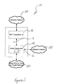
- a first embodiment 10 of communications apparatus according to the present invention is shown in Figure 1 .
- the communications apparatus 10 comprises a first circuit, which comprises a wired medium interface circuit 12 and a destination address controller 14, and a second circuit, which comprises a wireless medium interface circuit 16.
- the form and function of the destination address controller 14 will be described below with reference to Figure 2 .
- the communications apparatus 10 comprises an interface 18 (which constitutes a communications link) between the first and second circuits.
- the interface 18 is operative according to the Ethernet 802.3 standard.
- the wired medium interface circuit 12 comprises a core that is based on a home networking integrated circuit (a System on a Chip (SoC), such as the GGL541, from Gigle Networks Ltd of Capital House, 2 Festival Square, Edinburgh, EH3 9SU, UK), which is operative to receive and transmit data over wired media 20 comprising powerline, coaxial cable and twisted pair (such as is used for telephone lines).
- SoC System on a Chip
- the wired medium interface circuit 12 also comprises at least one external Ethernet interface for connection to an Ethernet network 22 and/or local devices, such as the local devices described below with reference to Figure 2 .
- the wireless medium interface circuit 16 is a known WiFi transceiver device in the form of a SoC operable according to at least one of the 802.11 standards, such as 802.11 a, 802.11 b, 802.11 g, 802.11 n, etc., and thus forms part of a WiFi network 24.
- the communications apparatus 10 of Figure 1 is operable to receive and transmit data to and from the wired medium interface circuit 12 and the wireless medium interface circuit 16 on a simultaneous basis, whereby a combined wireless and wired communications network may be formed from at least two such communications apparatus 10 as is described below with reference to Figure 2 . Provision for simultaneous communications by the wired medium interface circuit 12 and the wireless medium interface circuit 16 is described below with reference to Figure 5 .
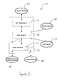
- FIG. 2 shows a communications network 30 having first 32 and second 34 nodes (which each constitute the communications apparatus of Figure 1 ).
- the communications network 30 comprises further un-illustrated nodes that are connected to each other and to the nodes shown in Figure 2 in the same fashion that the first and second nodes are connected to each other.
- the first and second nodes 32, 34 are connected to each other by already installed wired media 36 and by a WiFi link 38. More specifically, the already installed wired media consist of: a powerline cable; a coaxial cable; and a twisted pair telephone line.
- the network 30 of Figure 2 is used to provide for communication between and amongst a plurality of rooms in the building. Thus, for example, each of the nodes may be located in a different room of the residential building.
- Each of the first and second nodes 32, 34 is electrically connected to two devices.
- the first node 32 is connected to a laptop computer 40 and a television 42 and the second node 34 is connected to a Personal Computer (PC) 44 and a printer 46.
- PC Personal Computer
- Other un-illustrated nodes in a larger communications network than that represented in Figure 2 might, for example, be connected to a Home Gateway (HGW), audio-visual entertainment apparatus, etc.
- HGW Home Gateway
- the external Ethernet interface of each of the first and second nodes 32, 34 provides for a respective Ethernet connection 48, 50 to a respective two way Ethernet switch 52, 54.
- a first Ethernet switch 52 at the first node 32 is connected to the laptop computer 40 and the television 42 and a second Ethernet switch 54 at the second node 34 is connected to the PC 44 and the printer 46.
- the WiFi wireless medium interface circuits 16 at each node are capable of supporting only one MAC address.
- data for the printer 46 that is received wirelessly at the second node 34 from the first node 32 cannot be bridged to the printer according to known approaches (i.e. where the second node 34 supports WiFi communications only) because the wireless medium interface circuit 16 at the second node 34 cannot distinguish between the PC 44 and the printer 46.
- the destination address controllers 14 at each node are operative to implement a VLAN communications protocol in accordance with the IEEE 802.1 Q standard. More specifically, each destination address controller 14 is operative to modify data packets, which are to be transmitted, in accordance with the IEEE 802.1Q standard.
- each destination address controller 14 is operative to recognise a VLAN identifier in a data packet received at a node and to bridge the data to the identified device in dependence on the recognised VLAN identifier.
- the destination address controller 14 is comprised in the first, wired communications circuit.
- data that is to be transmitted over the WiFi link 38 is processed by the destination address controller 14 and then conveyed to the second circuit by the internal Ethernet interface 18.
- Data that is received over the WiFi link 38 is conveyed to the first circuit by the internal Ethernet interface 18 of the receiving communications apparatus for processing by its destination address controller 14.
- the destination address controller 14 in the first circuit controls all bridging irrespective of whether data is communicated by the wired link 36 or the WiFi link 38.
- the destination address controller 14 in each communications apparatus has the form of firmware resident in the home networking integrated circuit (i.e. the GGL541 SoC).
- Modification of the GGL541 SoC to implement the destination address controller 14 when reference is made to the content of the present application is within the ordinary design capabilities of the notionally skilled person when further reference is made to: product data from the vendor of a home networking chip, such as the GGL541, and the IEEE 802.1Q standard.
- the routing table (which constitutes a correspondence database) in each GGL541 is modified to relate each VLAN identifier to a MAC address and the interface; as mentioned above the assignment of VLAN identifiers to interfaces is described below with reference to Figure 4 .
- the first circuit comprises an Ethernet interface that connects to an Ethernet network 22 or a device.
- the Ethernet interface When the Ethernet interface is connected to an Ethernet network 22, a possible scenario is the reception of a data packet bearing a VLAN identifier that is the same as a VLAN identifier used in the network 30 of Figure 2 . Therefore, the first circuit is operative to determine whether or not a VLAN identifier of a data packet received from such an external Ethernet network 22 is the same as a VLAN identifier used in the wired and wireless communications network 30. If so, the first circuit is operative to replace the VLAN identifier with a temporary, network unique VLAN identifier before the data packet is transmitted on through the network. If the data packet is due to leave the network, the first circuit of the communications apparatus replaces the temporary, network unique VLAN identifier with the original VLAN identifier before the packet is transmitted from the network.
- one of the first and second nodes 32, 34 is configured as a master node.
- the master node is operative to control the wireless propagation of broadcast and multicast data through the network.
- the first circuit of the other communications apparatus and any further communications apparatus in a larger network is configured such that the other communications apparatus are incapable of sending broadcast and multicast data.
- wireless packet loops are avoided.
- network configuration information is received over the wired network and the modified routing table is configured in one of the nodes, e.g. the master node, before being copied to each of the other nodes in the network over the wired medium.
- a routing table can be configured or re-configured at each node based on configuration information received from the other nodes, whereby all nodes in the network have the same routing table.
- VLAN identification correspondence information is propagated throughout the communications network.
- a second embodiment 70 of communications apparatus according to the present invention is shown in Figure 3 .
- the second embodiment 70 is similar to the first embodiment in terms of it comprising a first circuit, which comprises a wired medium interface circuit 72 and a destination address controller 74, and a second circuit, which comprises a wireless medium interface circuit 76.
- the form and function of the destination address controller 74 is the same as for the destination address controller 14 of the first embodiment except as described below with reference to Figure 4 .
- the communications apparatus 70 comprises an interface 78 (which constitutes a communications link) between the first and second circuits.
- the interface 78 is operative according to the Ethernet 802.3 standard.
- the wired medium interface circuit 72 comprises a core that is based on a home networking integrated circuit (a GGL541 System on a Chip (SoC) from Gigle Networks Ltd.), which is operative to receive and transmit data over wired media 80 comprising powerline, coaxial cable and twisted pair.
- SoC System on a Chip
- the wired medium interface circuit 72 also comprises an external Ethernet interface for connection to an Ethernet network 82 or a local device as is described below with reference to Figure 4 .
- the wireless medium interface circuit 76 is a known WiFi transceiver device in the form of a SoC operable according to at least one of the 802.11 standards, such as 802.11 a, 802.11 b, 802.11 g, 802.11 n, etc., and thus forms part of a WiFi network 84.
- the second circuit of the communications apparatus 70 of Figure 3 further comprises a Wide Area Network (WAN) interface circuit 86 (which constitutes a WAN interface circuit).
- the WAN interface circuit 86 has an external Ethernet interface for communication over an Ethernet network 88 or connection to a local device (as described below with reference to Figure 4 ) and an external WAN interface for communication over a WAN network 90.
- the WAN interface circuit 86 also has an internal Ethernet interface, which is configured to provide for communications with the first circuit, which supports the wired communications, via the interface 78. Communication between the WAN interface circuit 86 and the wireless medium interface circuit 76 is by means of a communications link, such as an Ethernet or SDIO interface where the WAN and WiFi circuits form part of the same unit but are constituted as separate chipsets.
- the WAN interface circuit 86 is of known form and function, such as a circuit from Cisco, Juniper, Netgear or 3com.
- the communications apparatus 70 of Figure 3 is operable to receive and transmit data to and from the wired medium interface circuit 72 and the wireless medium interface circuit 76 on a simultaneous basis, whereby a combined wireless and wired communications network may be formed from at least two such communications apparatus 70 or communications apparatus 10 according to the first embodiment as is described below with reference to Figure 4 . Provision for simultaneous wired and wireless network communications by the wired medium interface circuit 72 and the wireless medium interface circuit 76 is described below with reference to Figure 5 .
- Figure 4 shows a communications network 100 having a first 102 node and a second 104 node.
- the first node 102 is formed by the communications apparatus 10 of Figure 1 and the second node 104 is formed by the communications apparatus 70 of Figure 3 .
- the communications network 100 of Figure 4 comprises further un-illustrated nodes that are connected to each other and to the nodes shown in Figure 4 in the same fashion that the first and second nodes are connected to each other.
- the first and second nodes 102, 104 are connected to each other by already installed wired media 106 and by a WiFi network 108. More specifically, the already installed wired media consist of: a powerline cable; a coaxial cable; and a twisted pair telephone line.
- the network 100 of Figure 4 is used to provide for communication between and amongst a plurality of rooms in a building.
- the first node 104 is connected to a single device, namely a first PC 110.
- the second node 106 is connected to two devices, namely a second PC 112 and a first laptop computer 114, with the second PC 112 being connected to the Ethernet interface of the first circuit (i.e. the GGL541) and the laptop computer being connected to the Ethernet interface of the WAN interface circuit.
- a second laptop computer 116 is connected to the wireless network 108 between the first and second nodes 102, 104 and a web server 118 is connected via the WAN to the WAN interface of the WAN interface circuit 86 of the second node 104.
- a data packet received via the wireless network 108 by the second node 104 may be intended for bridging to the second PC 112 or to the first laptop computer 114.
- the WiFi wireless medium interface circuit 76 at the second node is capable of supporting only one MAC address.
- data for the second PC 112 that is received wirelessly at the second node 104 cannot be bridged to the second first PC 112 according to known approaches because the wireless medium interface circuit 76 at the second node 104 cannot distinguish between the second PC 112 and the first laptop computer 114.
- the destination address controllers 14, 74 at each node are operative to implement a VLAN communications protocol in accordance with the IEEE 802.1Q standard as is described above with reference to the first embodiment. Therefore, a unique VLAN identifier can be attached to a data packet to provide for routing of the data packet to, for example, the second PC 112. Implementation of the VLAN communications protocol finds further application in distinguishing between and amongst interfaces of the second circuit. For example, a unique VLAN identifier is assigned to each of: the wireless interface formed by the wireless medium interface circuit 76; the WAN interface formed by the WAN interface circuit 86; and the external Ethernet interface formed by the WAN interface circuit 86.
- a VLAN identifier may be included in a data packet to determine whether the packet is transmitted from the second node 104 by the wireless interface, the WAN interface or the external Ethernet interface. Therefore, it can be appreciated that bridging control exerted by the first, wired communications circuit determines data flow though interfaces as well as to and from local and distant devices. Where a WAN interface comprises its own bridging control the bridging control exerted by the destination address controllers 14, 74 overrides the bridging control of the WAN interface. Implementation of the VLAN communications protocol finds yet further application in distinguishing between and amongst wired medium interfaces of the first circuit. Therefore, each of the powerline cable, coaxial cable and twisted pair interfaces is assigned a unique VLAN identifier so determine the wired medium by which a particular data packet will be conveyed.
- FIG. 5 An embodiment of communications apparatus 140 that supports simultaneous communication of data over wired and wireless media is represented in Figure 5 . More specifically, Figure 5 shows the physical and medium access control levels within the communications apparatus.
- the communications apparatus 140 of Figure 5 comprises a powerline medium transceiver 142 (which constitutes a first wired medium interface circuit), which is operative to interface with a powerline cable.
- the communications apparatus 140 also comprises a coaxial cable interface circuit 144 (which constitutes a second wired medium interface circuit), which is operative to interface with coaxial cable.
- the powerline medium transceiver 142 is controlled by a first Medium Access Controller (MAC) 146 and the coaxial cable interface circuit 144 is controlled by a second Medium Access Controller (MAC) 148.
- MAC Medium Access Controller
- a system Medium Access Controller 150 (which constitutes a communications controller) controls the splitting of data amongst the powerline cable, the coaxial cable and the wireless connection, as is described below in more detail.
- the hitherto described components are formed as part of a first System on a Chip (SoC) based upon the GGL541 mentioned above.
- SoC System on a Chip
- the hitherto described components constitute part of the first circuit described above with reference to Figures 1 and 2 .
- the communications apparatus 140 of Figure 5 further comprises an 802.11 compliant transceiver 152 (which constitutes a wireless medium interface circuit), which is operative to interface with the WiFi network 38, 108 of Figures 2 and 4 .
- the 802.11 compliant transceiver 152 is controlled by a third Medium Access Controller (MAC) 152.
- MAC Medium Access Controller
- Communication between the system Medium Access Controller 150 and the third Medium Access Controller 154 is by way of an Ethernet connection 18, 78, 156 (which constitutes a communications link between the first and second circuits).
- the further described components constitute part of the second circuit described above with reference to Figures 1 and 2 .
- Movie data is to be transmitted between the first 32 and second 34 nodes.
- Each of the first and second Medium Access Controllers 146, 148 is operative to obtain information from its respective channel relating to quality of service measures, such as available bandwidth, latency and extent of packet loss.
- the third Medium Access Controller 154 is operative to obtain information from the wireless network relating to quality of service measures, such as available bandwidth, latency and extent of packet loss; such information is conveyed to the system Medium Access Controller 150 by way of the Ethernet connection 156.
- a quality of service metric is determined as described in WO 2008/142450 (to the present applicant) or WO 2008/142449 (to the present applicant).
- the system Medium Access Controller 150 is operative to determine how data should be split amongst the powerline cable, the coaxial cable and the wireless network in dependence on the type of data being transmitted (i.e. a movie) and having regards to the quality of service information from the three media.
- the split data is then transmitted over the three media simultaneously.
- first and second media could be used to transmit while the third medium is used to receive or the first medium could be used to transmit and the second and third media used to receive.
- the first and third media could be used to receive while the second medium is used to transmit.
- one of the media may not be used such that, for example, the third medium is not used while the first and second media are both used to transmit or receive or the third medium is not used while one of the first and second media is used to transmit and the other of the first and second media is used to receive.
- the data packet is modified to include a VLAN identifier as described above. Also, when a data packet is received it is processed to recognise its unique VLAN identifier to thereby provide for proper bridging of the data packet.
Abstract
Description
- The present invention relates to communications apparatus and a communications network comprising such communications apparatus, in particular, but not exclusively, for application with multi-media apparatus. For example, the present invention may find application in Information Technology (IT) infrastructure apparatus, such as in routers, access points, network interface cards (NICs), Ethernet adapters, etc.
- It is known to provide for data communication between and amongst multi-media apparatus, which are installed, for example, in a residential or commercial building, by means of a communications network. The multi-media apparatus might, for example, comprise Network Attached Storage (NAS), a Home Gateway (HGW), a Personal Computer (PC), a television (TV), and a Set-Top Box (STB). Communication between and amongst such multi-media apparatus is by means of a wired medium interface circuit at each multi-media apparatus (or node) with the wired medium interface circuits being operative to communicate data from node to node over an appropriate wired medium. The medium interface circuit may be of the kind described in
WO 2008/142449 (to the present applicant), which is operative to transmit and receive data over one or more of powerlines, telephone lines and coaxial cables. - WiFi communications is finding widespread use in residential and commercial environments. Providing for communication between and amongst nodes in a communications network over a wired medium and by WiFi can be beneficial in respect of providing for improved coverage, ubiquity and reliability. Furthermore, channel conditions between two nodes can vary, for example in terms of attenuation, noise and group delay. Hence, it may be difficult to guarantee a high level of channel capacity on a particular medium. Using wired and WiFi communication in a network can minimise the effects of channel variation.
- An approach to providing a network having wired and WiFi communication is combining a wired medium interface circuit, such as that described in
WO 2008/142449 , with a WiFi transceiver at each network node. However, WiFi specifications impose a limit on the number of MAC addresses that a WiFi transceiver can support. More specifically and at present, a WiFi transceiver supports one MAC address. The present inventors have appreciated that if two or more devices are connected to a network node, for example at its Ethernet interface, the connected devices are not independently visible to the rest of the network when communication is by WiFi. For example, if a node in a network is connected by an Ethernet switch to a Personal Computer (PC) and a printer and data is received over the network by a WiFi transceiver at the node, the single MAC address means that the node is unable to determine whether the data is intended for the PC or the printer. - As mentioned above, the present inventors have appreciated that providing for wired and WiFi communications in a network presents a problem. It is therefore an object for the present invention to provide improved communications apparatus that is configured to communicate data over a wired medium and a wireless medium.
- According to a first aspect of the present invention there is provided a communications apparatus comprising:
- a first circuit comprising a wired medium interface circuit that is configured to, in use, communicate data over a wired medium;
- a second circuit comprising a wireless medium interface circuit that is configured to, in use, communicate data over a wireless medium; and
- a destination address controller comprised in the first circuit that is operative to determine to which of a plurality of destination addresses at a communications apparatus data is to be communicated from the second circuit.
- In use, the destination address controller is operative to determine to which of a plurality of destination addresses at a communications apparatus data is to be communicated. Thus, the communications apparatus can have individual visibility of plural destination addresses (e.g. for respective devices) when data is received or transmitted by the wireless medium interface circuit. Hence, the communications apparatus may overcome the limitation in MAC addresses supported by a wireless medium interface circuit, such as the sole MAC address supported by a WiFi transceiver. For example, it may be that the data is to be communicated to one of plural addresses, such as a first address for a PC and a second address for a printer, at another communications apparatus, with each of the plural addresses corresponding to a different device connected to the other communication apparatus. Hence, the destination address controller can provide for independent visibility of more than one device connected to the other communications apparatus. Also, the communications apparatus may be configured for communication over wired and wireless media when in use in a network. In contrast, certain known communications apparatus force a network to use of one or other of the wired and wireless media such that the network is either wired or wireless but not both. Hence, the destination address controller may be operative to determine to which of a plurality of destination addresses at a communications apparatus further data is to be communicated by the first circuit. The known Wireless Distribution System (WDS) can provide for routing of data to two or more devices connected to a WiFi enabled node in a WiFi communications network. However, WDS is configured for WiFi communication only and thus does not provide for communication in a network having both wireless and wired communication of data. Indeed, WDS is designed to be used in applications lacking wired links.
- Alternatively or in addition, the communications apparatus may be operative when in use such that at least one of the wired medium interface circuit and the wireless medium interface circuit transmits the data over its respective medium, e.g. to another communications apparatus having plural destination addresses.
- Alternatively or in addition, the communications apparatus may be operative when in use such that the second circuit communicates data (e.g. bridges data received from the wireless medium) to one of a plurality of devices connected to the same communications apparatus. Hence, the plural addresses may correspond to devices attached to the same communications apparatus. For example, the plurality of devices may be connected by an Ethernet connection to the communications apparatus. Hence, the wireless medium interface circuit of the communications apparatus may receive the data from another communications apparatus and the communications apparatus may bridge the received data to one of the plurality of devices in dependence on the destination address controller determining to which of the devices the data is to be communicated. The communications apparatus and the plural devices may be configured to be comprised in a node of a communications network.
- The destination address controller is comprised in the first circuit because the first circuit may be the only one of the first and second circuits that has individual visibility of plural destination addresses. Therefore, the communications apparatus may be operative to convey data received by the wireless medium interface circuit to the first circuit, in which the destination address controller is operative to determine the destination address for the data.
- Alternatively or in addition and where the second circuit is capable of determining a destination address, the communications apparatus may be configured such that operation of the destination address controller overrides an address determination made by the second circuit. Hence, all bridging decisions may be made by the first circuit. Certain known communications apparatus comprises a discrete wireless medium interface circuit, a discrete wired medium interface circuit and a routing engine. The discrete wireless and wired interface circuits are connected by an Ethernet interface and the routing engine is operative to direct data packets to one interface circuit or the other with each interface circuit making its own bridging decision. Thus, according to such known communications apparatus and in contrast with the present invention there is no destination address controller at the wired medium interface circuit that is operative to make bridging decisions for the wireless medium interface circuit.
- Alternatively or in addition, the communications apparatus may further comprise a communications link between the first and second circuits, the communications link operating according to a frame based standard, such as Ethernet according to the 802.3 standard. The Ethernet standard may be transmitted across one of several inter system connections, such as one of the following: MII, RMII, RvMII, GMII, RGMII, SMII, 10/100, 10/100/1000, USB1.1, USB2, USB3, SDIO, PCIe and PCI. Hence, the communications link may be operative to convey data received by the wired medium interface to the second circuit and to convey data received by the wireless medium interface circuit to the first circuit.
- Alternatively or in addition, the destination address controller may be constituted in software, such as firmware operating on the first circuit. Hence, there may be no need to develop the hardware of the first circuit to implement the destination address controller. More specifically, the destination address controller may be operative to implement a communications protocol that is operative to identify each of the plurality of destination addresses. For example, the protocol may be operative to assign a unique address identifier to each of the plurality of destination addresses where the destination addresses are connected to another communications apparatus. Alternatively, the protocol may be operative to recognise a unique address identifier corresponding to one of the plurality of destination addresses where the destination addresses identify plural devices attached to the communications apparatus.
- Alternatively or in addition, the destination address controller may be operative to implement a communications protocol that is operative at the data link layer (i.e.
Layer 2 of the OSI model). Thus, the communications protocol may be operative to include destination address identification information in a data packet transmitted by the communications apparatus. Alternatively, the communications protocol may be operative to recognise destination address identification information in a data packet received by the communications apparatus. Hence, the destination address controller may be operative to implement a virtual LAN (VLAN) with each destination address having a unique VLAN identifier. More specifically, the communications protocol may be in accordance with the IEEE 802.1 Q standard. - Alternatively or in addition, the communications apparatus may further comprise a communications controller that is operative to provide for selective communication of data over each of the wired medium and the wireless medium. Selective communication of data may be in dependence on at least one of: network traffic load; quality of service requirements (such as latency, jitter and guaranteed bandwidth); available channel capacity; and number of hops. Data may be communicated simultaneously over the wired medium and the wireless medium. Such simultaneously communicated data may be different data sent to or received from the same or different destinations. Also, such simultaneously communicated data may be the same data sent to or received from the same or different destinations. The wired medium interface circuit and the wireless medium interface circuit may operate asynchronously of each other. Hence, performance may be improved by splitting data between the two media. Also, performance may be improved by using the two media at the same time.
- More specifically, the communications apparatus may further comprise a wired medium access controller, which is operative to control the wired medium interface circuit, and a wireless medium access controller, which is operative to control the wireless medium interface circuit. Therefore the communications controller may be a system medium access controller that is operative to control each of the wired and wireless medium access controllers.
- In a form, the second circuit may further comprise a Wide Area Network (WAN) interface circuit that is configured to, in use, communicate data over a WAN.
- More specifically, the communications apparatus may further comprise a communications link between the first circuit and the WAN interface circuit of the second circuit. The communications link may operate according to a frame based standard, such as Ethernet according to the 802.3 standard. The communications apparatus may further comprise a communications link between the WAN interface circuit and the wireless medium interface circuit. Hence, the destination address controller at the first circuit may control whether data is transmitted over the WAN or over the wireless network. Thus, the WAN interface circuit and the wireless medium interface circuit may constitute the destination addresses at the communications apparatus, whereby bridging decisions are taken at the first circuit. For example and where the destination address controller is operative to implement a VLAN, each interface of the second circuit other than an interface between the first and second circuits may have a unique VLAN identifier. Also, each of the interfaces for the plural wired media at the first circuit may be assigned a unique VLAN identifier. This is because a single MAC address is used for all the wired media interfaces at the first circuit.
- Alternatively or in addition, the second circuit may comprise a plurality of further interfaces, e.g. wireless, WAN or Ethernet, other than an interface, e.g. Ethernet, between the first and second circuits and each of the plurality of further interfaces may correspond to a different one of a plurality of destination addresses.
- Alternatively or in addition and where the WAN interface circuit is capable of determining a destination address, the communications apparatus may be configured such that operation of the destination address controller overrides an address determination made by the WAN interface circuit.
- Alternatively or in addition, the first circuit may form part of a first discrete apparatus, such as a first System on a Chip (SoC). Hence, the destination address controller may be comprised in the first SoC. Alternatively or in addition, second first circuit may form part of a second discrete apparatus, such as a second System on a Chip (SoC). The first and second circuits may be separate from each other with communication between the first and second circuits being by means of an interface, such as a serial interface. Where the second circuit comprises a WAN interface circuit, the wireless medium interface circuit may form part of a second discrete apparatus, such as a second System on a Chip (SoC), and the WAN interface circuit may form part of a third discrete interface circuit, such as a third System on a Chip (SoC).
- Alternatively or in addition, a medium interface circuit may be configured to operate as a transceiver. Hence, the medium interface circuit may be operable to receive and transmit data.
- Alternatively or in addition, the wireless medium interface circuit may be configured for at least one of: communication in accordance with one of the IEEE 802.11 standards (i.e. WiFi); Ultra-wideband (UWB) communication; and 60 GHz communication.
- Alternatively or in addition, the wired medium interface circuit may be configured for communication over at least one of: powerline; twisted pair; and coaxial cable.
- Alternatively or in addition, a destination address may correspond to at least one of: a device, such as a multi-media device, connected to one of the communications apparatus itself or another communications apparatus; and an interface circuit, such as a wireless interface circuit or a WAN interface circuit, forming part of the communications apparatus itself or another communications apparatus.
- Alternatively or in addition, the communications apparatus may comprise a correspondence database, the correspondence database relating each destination address to a different one of a device (e.g. in the form of a MAC address) and an interface circuit.
- Alternatively or in addition and where the second circuit comprises an external interface other than the wireless medium interface and a communications link between the first and second circuits, the communications apparatus may be operative: to convey data received at the external interface to the first circuit, the data having an external destination address; and to assign a temporary destination address, such as a VLAN identifier, to the conveyed data if the external destination address is the same as one of the plurality of destination addresses operated upon by the destination address controller. More specifically, the communications apparatus may be operative to replace the temporary destination address with the external destination address when the data is transmitted from the communications apparatus, e.g. when the data leaves a communications network comprising the communications apparatus.
- Alternatively or in addition, the communications apparatus may be configured to form part of a network comprising at least one further communications apparatus.
- Hence and according to a second aspect of the present invention, there is provided a communications network comprising plural communications apparatus, each communications apparatus being in accordance with the first aspect of the present invention.
- Alternatively or in addition, a first communications apparatus may comprise a correspondence database, the correspondence database relating each destination address, such as a VLAN identifier, to a different one of a device (e.g. in the form of a MAC address) and an interface circuit. The correspondence database may be operative with the destination address controller to determine the destination address to which data is to be communicated. More specifically, the first communications apparatus and a second communications apparatus may be operative to convey the correspondence database from the first communications apparatus to the second communications apparatus over the wired medium. Hence, destination address information may be propagated throughout the communications network.
- Alternatively or in addition, the communications network may comprise at least one device connected to at least one node of the communications network. A device may be multi-media apparatus or IT infrastructure apparatus, such as a router, an access point, a network interface card (NIC) or an Ethernet adapter.
- Further embodiments of the second aspect of the present invention may comprise one or more features of the first aspect of the present invention. According to an aspect of the invention, a communications apparatus comprises:
- a first circuit comprising a wired medium interface circuit that is configured to, in use, communicate data over a wired medium;
- a second circuit comprising a wireless medium interface circuit that is configured to, in use, communicate data over a wireless medium; and
- a destination address controller comprised in the first circuit that is operative to determine to which of a plurality of destination addresses at a communications apparatus data is to be communicated from the second circuit.
- Advantageously, the communications apparatus is configured to be operative when in use such that at least one of the wired medium interface circuit and the wireless medium interface circuit transmits the data over its respective medium.
- Advantageously, the communications apparatus is configured to be operative when in use such that the second circuit communicates data to one of a plurality of devices connected to the same communications apparatus.
- Advantageously, the communications apparatus is configured to be operative to convey data received by the wireless medium interface circuit to the first circuit, in which the destination address controller is operative to determine the destination address for the data.
- Advantageously, the second circuit is capable of determining a destination address, in which the communications apparatus is configured such that operation of the destination address controller overrides an address determination made by the second circuit.
- Advantageously, the communications apparatus further comprises a communications link between the first and second circuits, the communications link operating according to a frame based standard.
- Advantageously, the destination address controller is constituted in software.
- Advantageously, the destination address controller is operative to implement a communications protocol that is operative to identify each of the plurality of destination addresses.
- Advantageously, the destination address controller is operative to implement a communications protocol that is operative to recognise a unique address identifier corresponding to one of the plurality of destination addresses where the destination addresses identify plural devices attached to the communications apparatus.
- Advantageously, the destination address controller is operative to implement a communications protocol that is operative at the data link layer.
- Advantageously, the communications protocol is operative to include destination address identification information in a data packet transmitted by the communications apparatus.
- Advantageously, the communications protocol is operative to recognise destination address identification information in a data packet received by the communications apparatus.
- Advantageously, the destination address controller is operative to implement a virtual LAN (VLAN) with each destination address having a unique VLAN identifier.
- Advantageously, the communications protocol is in accordance with the IEEE 802.1Q standard.
- Advantageously, the communications apparatus further comprises a communications controller that is operative to provide for selective communication of data over each of the wired medium and the wireless medium.
- Advantageously, selective communication of data is in dependence on at least one of: network traffic load; quality of service requirements; available channel capacity; and number of hops.
- Advantageously, data is communicated simultaneously over the wired medium and the wireless medium, with such simultaneously communicated data being different data sent to or received from the same or different destinations.
- Advantageously, data is communicated simultaneously over the wired medium and the wireless medium, with such simultaneously communicated data being the same data sent to or received from the same or different destinations.
- Advantageously, the wired medium interface circuit and the wireless medium interface circuit operate asynchronously of each other.
- Advantageously, the communications apparatus further comprises a wired medium access controller, which is operative to control the wired medium interface circuit, and a wireless medium access controller, which is operative to control the wireless medium interface circuit.
- Advantageously, the second circuit further comprises a Wide Area Network (WAN) interface circuit that is configured to, in use, communicate data over a WAN.
- Advantageously, the communications apparatus further comprises a communications link between the first circuit and the WAN interface circuit of the second circuit.
- Advantageously, the communications link operates according to a frame based standard.
- Advantageously, the communications apparatus further comprises a communications link between the WAN interface circuit and the wireless medium interface circuit.
- Advantageously, the second circuit comprises a plurality of further interfaces other than an interface between the first and second circuits and each of the plurality of further interfaces correspond to a different one of a plurality of destination addresses.
- Advantageously, the second circuit further comprises a Wide Area Network (WAN) interface circuit that is configured to, in use, communicate data over a WAN and where the WAN interface circuit is capable of determining a destination address, the communications apparatus is configured such that operation of the destination address controller overrides an address determination made by the WAN interface circuit.
- Advantageously, the first circuit forms part of a first discrete apparatus and the second circuit forms part of a second discrete apparatus.
- Advantageously, communication between the first and second circuits is by means of an interface.
- Advantageously, the wireless medium interface circuit is configured for at least one of: communication in accordance with one of the IEEE 802.11 standards (i.e. WiFi); Ultra-wideband (UWB) communication; and 60 GHz communication.
- Advantageously, the wired medium interface circuit is configured for communication over at least one of: powerline; twisted pair; and coaxial cable.
- Advantageously, a destination address corresponds to at least one of: a device connected to one of the communications apparatus itself or another communications apparatus; and an interface circuit forming part of the communications apparatus itself or another communications apparatus.
- Advantageously, the communications apparatus comprises a correspondence database, the correspondence database relating each destination address to a different one of a device and an interface circuit.
- Advantageously, the communications apparatus is configured to form part of a network comprising at least one further communications apparatus. According to a further aspect, a communications network comprises plural communications apparatus, each communications apparatus being in accordance with any one of the preceding claims.
- Advantageously, a first communications apparatus comprises a correspondence database, the correspondence database relating each destination address to a different one of a device and an interface circuit, the correspondence database being operative with the destination address controller to determine the destination address to which data is to be communicated.
- Advantageously, the first communications apparatus and a second communications apparatus are operative to convey the correspondence database from the first communications apparatus to the second communications apparatus over the wired medium.
- Advantageously, the communications network comprises at least one device connected to at least one node of the communications network, the device being one of multi-media apparatus and IT infrastructure apparatus.
- Further features and advantages of the present invention will become apparent from the following specific description, which is given by way of example only and with reference to the accompanying drawings, in which:
-
Figure 1 is a representation of a first embodiment of the present invention; -
Figure 2 is a representation of the first embodiment when used in a communications network; -
Figure 3 is a representation of a second embodiment of the present invention; -
Figure 4 is a representation of the first and second embodiments when used in a communications network; and -
Figure 5 is a representation of physical and medium access control layers in the communications apparatus ofFigure 1 . - A
first embodiment 10 of communications apparatus according to the present invention is shown inFigure 1 . Thecommunications apparatus 10 comprises a first circuit, which comprises a wiredmedium interface circuit 12 and adestination address controller 14, and a second circuit, which comprises a wirelessmedium interface circuit 16. The form and function of thedestination address controller 14 will be described below with reference toFigure 2 . In addition, thecommunications apparatus 10 comprises an interface 18 (which constitutes a communications link) between the first and second circuits. Theinterface 18 is operative according to the Ethernet 802.3 standard. The wiredmedium interface circuit 12 comprises a core that is based on a home networking integrated circuit (a System on a Chip (SoC), such as the GGL541, from Gigle Networks Ltd of Capital House, 2 Festival Square, Edinburgh, EH3 9SU, UK), which is operative to receive and transmit data over wiredmedia 20 comprising powerline, coaxial cable and twisted pair (such as is used for telephone lines). The wiredmedium interface circuit 12 also comprises at least one external Ethernet interface for connection to anEthernet network 22 and/or local devices, such as the local devices described below with reference toFigure 2 . The wirelessmedium interface circuit 16 is a known WiFi transceiver device in the form of a SoC operable according to at least one of the 802.11 standards, such as 802.11 a, 802.11 b, 802.11 g, 802.11 n, etc., and thus forms part of aWiFi network 24. Wi-Fi is a certification mark devised by the Wi-Fi Alliance to indicate that a wireless local area network (WLAN) product is based on the Institute of Electrical and Electronics Engineers' (IEEE) 802.11 standards (see http://www.wi-fi.org/knowledge center overview.php?type=3#W). Reference should be made to publicly available product data from the vendor of the GGL541 and from a vendor of a wireless communications circuit, such as Intel, Broadcom, Marvell, Ralink, Atheros and CSR; such product data provides sufficient information for the skilled person to implement thecommunications apparatus 10 shown inFigure 1 with the exception of thedestination address controller 14 and the simultaneous communications by the wired and wireless medium interface circuits without resorting to any more than ordinary design skill. Thecommunications apparatus 10 ofFigure 1 is operable to receive and transmit data to and from the wiredmedium interface circuit 12 and the wirelessmedium interface circuit 16 on a simultaneous basis, whereby a combined wireless and wired communications network may be formed from at least twosuch communications apparatus 10 as is described below with reference toFigure 2 . Provision for simultaneous communications by the wiredmedium interface circuit 12 and the wirelessmedium interface circuit 16 is described below with reference toFigure 5 . -
Figure 2 shows acommunications network 30 having first 32 and second 34 nodes (which each constitute the communications apparatus ofFigure 1 ). Thecommunications network 30 comprises further un-illustrated nodes that are connected to each other and to the nodes shown inFigure 2 in the same fashion that the first and second nodes are connected to each other. The first andsecond nodes 32, 34 are connected to each other by already installedwired media 36 and by aWiFi link 38. More specifically, the already installed wired media consist of: a powerline cable; a coaxial cable; and a twisted pair telephone line. Thenetwork 30 ofFigure 2 is used to provide for communication between and amongst a plurality of rooms in the building. Thus, for example, each of the nodes may be located in a different room of the residential building. Each of the first andsecond nodes 32, 34 is electrically connected to two devices. Thus, thefirst node 32 is connected to alaptop computer 40 and atelevision 42 and the second node 34 is connected to a Personal Computer (PC) 44 and aprinter 46. Other un-illustrated nodes in a larger communications network than that represented inFigure 2 might, for example, be connected to a Home Gateway (HGW), audio-visual entertainment apparatus, etc. The external Ethernet interface of each of the first andsecond nodes 32, 34 provides for arespective Ethernet connection way Ethernet switch first Ethernet switch 52 at thefirst node 32 is connected to thelaptop computer 40 and thetelevision 42 and asecond Ethernet switch 54 at the second node 34 is connected to thePC 44 and theprinter 46. - As explained above, the WiFi wireless
medium interface circuits 16 at each node are capable of supporting only one MAC address. Hence, data for theprinter 46 that is received wirelessly at the second node 34 from thefirst node 32 cannot be bridged to the printer according to known approaches (i.e. where the second node 34 supports WiFi communications only) because the wirelessmedium interface circuit 16 at the second node 34 cannot distinguish between thePC 44 and theprinter 46. According to the present invention, thedestination address controllers 14 at each node are operative to implement a VLAN communications protocol in accordance with the IEEE 802.1 Q standard. More specifically, eachdestination address controller 14 is operative to modify data packets, which are to be transmitted, in accordance with the IEEE 802.1Q standard. Thus, a unique VLAN identifier is used for each device, e.g. thePC 44 and theprinter 46, such that a transmitted packet contains a VLAN device identifier for a particular device. VLAN identifiers can also be assigned to interfaces of communications apparatus as well as devices connected to communications apparatus. The assignment of VLAN identifiers to interfaces will be described below with reference toFigure 4 . Hence, eachdestination address controller 14 is operative to recognise a VLAN identifier in a data packet received at a node and to bridge the data to the identified device in dependence on the recognised VLAN identifier. As can be seen fromFigure 1 , thedestination address controller 14 is comprised in the first, wired communications circuit. Hence, data that is to be transmitted over theWiFi link 38 is processed by thedestination address controller 14 and then conveyed to the second circuit by theinternal Ethernet interface 18. Data that is received over theWiFi link 38 is conveyed to the first circuit by theinternal Ethernet interface 18 of the receiving communications apparatus for processing by itsdestination address controller 14. Thus, it can be appreciated that thedestination address controller 14 in the first circuit controls all bridging irrespective of whether data is communicated by thewired link 36 or theWiFi link 38. Thedestination address controller 14 in each communications apparatus has the form of firmware resident in the home networking integrated circuit (i.e. the GGL541 SoC). Modification of the GGL541 SoC to implement thedestination address controller 14 when reference is made to the content of the present application is within the ordinary design capabilities of the notionally skilled person when further reference is made to: product data from the vendor of a home networking chip, such as the GGL541, and the IEEE 802.1Q standard. The routing table (which constitutes a correspondence database) in each GGL541 is modified to relate each VLAN identifier to a MAC address and the interface; as mentioned above the assignment of VLAN identifiers to interfaces is described below with reference toFigure 4 . - As can be seen in
Figure 1 , the first circuit comprises an Ethernet interface that connects to anEthernet network 22 or a device. When the Ethernet interface is connected to anEthernet network 22, a possible scenario is the reception of a data packet bearing a VLAN identifier that is the same as a VLAN identifier used in thenetwork 30 ofFigure 2 . Therefore, the first circuit is operative to determine whether or not a VLAN identifier of a data packet received from such anexternal Ethernet network 22 is the same as a VLAN identifier used in the wired andwireless communications network 30. If so, the first circuit is operative to replace the VLAN identifier with a temporary, network unique VLAN identifier before the data packet is transmitted on through the network. If the data packet is due to leave the network, the first circuit of the communications apparatus replaces the temporary, network unique VLAN identifier with the original VLAN identifier before the packet is transmitted from the network. - In the
network 30 ofFigure 2 , one of the first andsecond nodes 32, 34 is configured as a master node. The master node is operative to control the wireless propagation of broadcast and multicast data through the network. In addition, the first circuit of the other communications apparatus and any further communications apparatus in a larger network is configured such that the other communications apparatus are incapable of sending broadcast and multicast data. Hence, wireless packet loops are avoided. When the network is being configured or re-configured, network configuration information is received over the wired network and the modified routing table is configured in one of the nodes, e.g. the master node, before being copied to each of the other nodes in the network over the wired medium. Alternatively, a routing table can be configured or re-configured at each node based on configuration information received from the other nodes, whereby all nodes in the network have the same routing table. Hence, VLAN identification correspondence information is propagated throughout the communications network. - A second embodiment 70 of communications apparatus according to the present invention is shown in
Figure 3 . The second embodiment 70 is similar to the first embodiment in terms of it comprising a first circuit, which comprises a wired medium interface circuit 72 and adestination address controller 74, and a second circuit, which comprises a wirelessmedium interface circuit 76. The form and function of thedestination address controller 74 is the same as for thedestination address controller 14 of the first embodiment except as described below with reference toFigure 4 . In addition, the communications apparatus 70 comprises an interface 78 (which constitutes a communications link) between the first and second circuits. Theinterface 78 is operative according to the Ethernet 802.3 standard. As with the first embodiment, the wired medium interface circuit 72 comprises a core that is based on a home networking integrated circuit (a GGL541 System on a Chip (SoC) from Gigle Networks Ltd.), which is operative to receive and transmit data over wiredmedia 80 comprising powerline, coaxial cable and twisted pair. The wired medium interface circuit 72 also comprises an external Ethernet interface for connection to anEthernet network 82 or a local device as is described below with reference toFigure 4 . As with the first embodiment, the wirelessmedium interface circuit 76 is a known WiFi transceiver device in the form of a SoC operable according to at least one of the 802.11 standards, such as 802.11 a, 802.11 b, 802.11 g, 802.11 n, etc., and thus forms part of aWiFi network 84. The second circuit of the communications apparatus 70 ofFigure 3 further comprises a Wide Area Network (WAN) interface circuit 86 (which constitutes a WAN interface circuit). TheWAN interface circuit 86 has an external Ethernet interface for communication over anEthernet network 88 or connection to a local device (as described below with reference toFigure 4 ) and an external WAN interface for communication over aWAN network 90. TheWAN interface circuit 86 also has an internal Ethernet interface, which is configured to provide for communications with the first circuit, which supports the wired communications, via theinterface 78. Communication between theWAN interface circuit 86 and the wirelessmedium interface circuit 76 is by means of a communications link, such as an Ethernet or SDIO interface where the WAN and WiFi circuits form part of the same unit but are constituted as separate chipsets. TheWAN interface circuit 86 is of known form and function, such as a circuit from Cisco, Juniper, Netgear or 3com. - As with the first embodiment, reference should be made to publicly available product data from the vendor of the GGL541 and from a vendor of a wireless communications circuit and of a WAN interface circuit; such product data provides sufficient information for the skilled person to implement the communications apparatus 70 of
Figure 3 with the exception of thedestination address controller 74 and the simultaneous communications by the wired and wireless medium interface circuits without resorting to any more than ordinary design skill. The communications apparatus 70 ofFigure 3 is operable to receive and transmit data to and from the wired medium interface circuit 72 and the wirelessmedium interface circuit 76 on a simultaneous basis, whereby a combined wireless and wired communications network may be formed from at least two such communications apparatus 70 orcommunications apparatus 10 according to the first embodiment as is described below with reference toFigure 4 . Provision for simultaneous wired and wireless network communications by the wired medium interface circuit 72 and the wirelessmedium interface circuit 76 is described below with reference toFigure 5 . -
Figure 4 shows a communications network 100 having a first 102 node and a second 104 node. Thefirst node 102 is formed by thecommunications apparatus 10 ofFigure 1 and thesecond node 104 is formed by the communications apparatus 70 ofFigure 3 . The communications network 100 ofFigure 4 comprises further un-illustrated nodes that are connected to each other and to the nodes shown inFigure 4 in the same fashion that the first and second nodes are connected to each other. The first andsecond nodes wired media 106 and by aWiFi network 108. More specifically, the already installed wired media consist of: a powerline cable; a coaxial cable; and a twisted pair telephone line. The network 100 ofFigure 4 is used to provide for communication between and amongst a plurality of rooms in a building. Thefirst node 104 is connected to a single device, namely afirst PC 110. Thesecond node 106 is connected to two devices, namely asecond PC 112 and afirst laptop computer 114, with thesecond PC 112 being connected to the Ethernet interface of the first circuit (i.e. the GGL541) and the laptop computer being connected to the Ethernet interface of the WAN interface circuit. In addition, asecond laptop computer 116 is connected to thewireless network 108 between the first andsecond nodes web server 118 is connected via the WAN to the WAN interface of theWAN interface circuit 86 of thesecond node 104. - As can be seen from
Figure 3 , a data packet received via thewireless network 108 by thesecond node 104 may be intended for bridging to thesecond PC 112 or to thefirst laptop computer 114. However and as discussed above, the WiFi wirelessmedium interface circuit 76 at the second node is capable of supporting only one MAC address. Hence, data for thesecond PC 112 that is received wirelessly at thesecond node 104 cannot be bridged to the secondfirst PC 112 according to known approaches because the wirelessmedium interface circuit 76 at thesecond node 104 cannot distinguish between thesecond PC 112 and thefirst laptop computer 114. According to the present invention, thedestination address controllers second PC 112. Implementation of the VLAN communications protocol finds further application in distinguishing between and amongst interfaces of the second circuit. For example, a unique VLAN identifier is assigned to each of: the wireless interface formed by the wirelessmedium interface circuit 76; the WAN interface formed by theWAN interface circuit 86; and the external Ethernet interface formed by theWAN interface circuit 86. Hence, a VLAN identifier may be included in a data packet to determine whether the packet is transmitted from thesecond node 104 by the wireless interface, the WAN interface or the external Ethernet interface. Therefore, it can be appreciated that bridging control exerted by the first, wired communications circuit determines data flow though interfaces as well as to and from local and distant devices. Where a WAN interface comprises its own bridging control the bridging control exerted by thedestination address controllers - An embodiment of
communications apparatus 140 that supports simultaneous communication of data over wired and wireless media is represented inFigure 5 . More specifically,Figure 5 shows the physical and medium access control levels within the communications apparatus. Thecommunications apparatus 140 ofFigure 5 comprises a powerline medium transceiver 142 (which constitutes a first wired medium interface circuit), which is operative to interface with a powerline cable. In addition, thecommunications apparatus 140 also comprises a coaxial cable interface circuit 144 (which constitutes a second wired medium interface circuit), which is operative to interface with coaxial cable. The powerline medium transceiver 142 is controlled by a first Medium Access Controller (MAC) 146 and the coaxialcable interface circuit 144 is controlled by a second Medium Access Controller (MAC) 148. A system Medium Access Controller 150 (which constitutes a communications controller) controls the splitting of data amongst the powerline cable, the coaxial cable and the wireless connection, as is described below in more detail. The hitherto described components are formed as part of a first System on a Chip (SoC) based upon the GGL541 mentioned above. The hitherto described components constitute part of the first circuit described above with reference toFigures 1 and2 . - The
communications apparatus 140 ofFigure 5 further comprises an 802.11 compliant transceiver 152 (which constitutes a wireless medium interface circuit), which is operative to interface with theWiFi network Figures 2 and4 . The 802.11compliant transceiver 152 is controlled by a third Medium Access Controller (MAC) 152. Communication between the systemMedium Access Controller 150 and the thirdMedium Access Controller 154 is by way of anEthernet connection Figures 1 and2 . - The operation of the communications apparatus of
Figure 5 will now be described with reference toFigures 2 and5 . Movie data is to be transmitted between the first 32 and second 34 nodes. Each of the first and secondMedium Access Controllers 146, 148 is operative to obtain information from its respective channel relating to quality of service measures, such as available bandwidth, latency and extent of packet loss. Also, the thirdMedium Access Controller 154 is operative to obtain information from the wireless network relating to quality of service measures, such as available bandwidth, latency and extent of packet loss; such information is conveyed to the systemMedium Access Controller 150 by way of theEthernet connection 156. A quality of service metric is determined as described inWO 2008/142450 (to the present applicant) orWO 2008/142449 (to the present applicant). Then the systemMedium Access Controller 150 is operative to determine how data should be split amongst the powerline cable, the coaxial cable and the wireless network in dependence on the type of data being transmitted (i.e. a movie) and having regards to the quality of service information from the three media. The split data is then transmitted over the three media simultaneously. - Alternatively there could be more than one flow of data (e.g. more than one movie) to be transmitted and/or received, that is, communicated between the first and
second nodes 32, 34. Data can be received and/or transmitted using any combination of media in an asynchronous fashion. Thus, for example, the first and second media could be used to transmit while the third medium is used to receive or the first medium could be used to transmit and the second and third media used to receive. Alternatively, the first and third media could be used to receive while the second medium is used to transmit. Also, one of the media may not be used such that, for example, the third medium is not used while the first and second media are both used to transmit or receive or the third medium is not used while one of the first and second media is used to transmit and the other of the first and second media is used to receive. When data packets are being framed for transmission, the data packet is modified to include a VLAN identifier as described above. Also, when a data packet is received it is processed to recognise its unique VLAN identifier to thereby provide for proper bridging of the data packet.
Claims (15)
- A communications apparatus comprising:a first circuit comprising a wired medium interface circuit that is configured to, in use, communicate data over a wired medium;a second circuit comprising a wireless medium interface circuit that is configured to, in use, communicate data over a wireless medium; anda destination address controller comprised in the first circuit that is operative to determine to which of a plurality of destination addresses at a communications apparatus data is to be communicated from the second circuit.
- The communications apparatus of claim 1 configured to be operative when in use such that at least one of the wired medium interface circuit and the wireless medium interface circuit transmits the data over its respective medium.
- The communications apparatus of claim 1 or 2 configured to be operative when in use such that the second circuit communicates data to one of a plurality of devices connected to the same communications apparatus.
- The communications apparatus of any preceding claim configured to be operative to convey data received by the wireless medium interface circuit to the first circuit, in which the destination address controller is operative to determine the destination address for the data.
- The communications apparatus of any preceding claim and where the second circuit is capable of determining a destination address, in which the communications apparatus is configured such that operation of the destination address controller overrides an address determination made by the second circuit.
- The communications apparatus of any preceding claim further comprising a communications link between the first and second circuits, the communications link operating according to a frame based standard.
- The communications apparatus of any preceding claim, in which the destination address controller is constituted in software.
- The communications apparatus of any preceding claim, in which the destination address controller is operative to implement a communications protocol that is operative to identify each of the plurality of destination addresses.
- The communications apparatus of any preceding claim, in which the destination address controller is operative to implement a communications protocol that is operative to recognise a unique address identifier corresponding to one of the plurality of destination addresses where the destination addresses identify plural devices attached to the communications apparatus.
- The communications apparatus of any preceding claim, in which the destination address controller is operative to implement a communications protocol that is operative at the data link layer.
- The communications apparatus of claim 10, in which the communications protocol is operative to include destination address identification information in a data packet transmitted by the communications apparatus.
- The communications apparatus of claim 10, in which the communications protocol is operative to recognise destination address identification information in a data packet received by the communications apparatus.
- The communications apparatus of any one of claims 10 to 12, in which the destination address controller is operative to implement a virtual LAN (VLAN) with each destination address having a unique VLAN identifier.
- A communications network comprising plural communications apparatus, each communications apparatus being in accordance with any one of the preceding claims.
- The communications network of claim 14, in which a first communications apparatus comprises a correspondence database, the correspondence database relating each destination address to a different one of a device and an interface circuit, the correspondence database being operative with the destination address controller to determine the destination address to which data is to be communicated.
Applications Claiming Priority (1)
| Application Number | Priority Date | Filing Date | Title |
|---|---|---|---|
| GBGB1008633.8A GB201008633D0 (en) | 2010-05-24 | 2010-05-24 | Communications apparatus |
Publications (2)
| Publication Number | Publication Date |
|---|---|
| EP2391070A1 true EP2391070A1 (en) | 2011-11-30 |
| EP2391070B1 EP2391070B1 (en) | 2016-08-03 |
Family
ID=42341214
Family Applications (1)
| Application Number | Title | Priority Date | Filing Date |
|---|---|---|---|
| EP11004270.2A Active EP2391070B1 (en) | 2010-05-24 | 2011-05-24 | A communication apparatus for hybrid wired and wireless communications |
Country Status (3)
| Country | Link |
|---|---|
| US (1) | US9225551B2 (en) |
| EP (1) | EP2391070B1 (en) |
| GB (1) | GB201008633D0 (en) |
Cited By (1)
| Publication number | Priority date | Publication date | Assignee | Title |
|---|---|---|---|---|
| EP3068087A4 (en) * | 2013-11-04 | 2017-07-12 | Huizhou TCL Mobile Communication Co., Ltd. | Method and system for transmitting data parallelly on wireless link and wired link |
Families Citing this family (10)
| Publication number | Priority date | Publication date | Assignee | Title |
|---|---|---|---|---|
| TWI466519B (en) * | 2010-11-29 | 2014-12-21 | Realtek Semiconductor Corp | Network device and network connecting method |
| EP2663047B1 (en) * | 2012-05-10 | 2018-07-04 | Lantiq Beteiligungs-GmbH & Co.KG | Data transmission using different transmission technologies |
| US10044613B2 (en) * | 2013-05-16 | 2018-08-07 | Intel IP Corporation | Multiple radio link control (RLC) groups |
| CN103593147B (en) * | 2013-11-07 | 2016-08-17 | 华为技术有限公司 | A kind of method and device of digital independent |
| US9853676B2 (en) * | 2014-09-30 | 2017-12-26 | Apple Inc. | Alternative routing of wireless data onto power supply |
| AU2017100239A4 (en) * | 2014-09-30 | 2017-03-30 | Apple Inc. | Alternative routing of wireless data onto power supply |
| US10362011B2 (en) * | 2015-07-12 | 2019-07-23 | Qualcomm Incorporated | Network security architecture |
| US20180197501A1 (en) * | 2017-01-06 | 2018-07-12 | Intel Corporation | Display connection switching |
| US11032143B2 (en) * | 2018-08-03 | 2021-06-08 | Netapp, Inc. | Assignment of network configuration for a wired network using a wireless network |
| WO2020055294A1 (en) * | 2018-09-12 | 2020-03-19 | Telefonaktiebolaget Lm Ericsson (Publ) | Traffic splitting device |
Citations (7)
| Publication number | Priority date | Publication date | Assignee | Title |
|---|---|---|---|---|
| WO2006119573A1 (en) * | 2005-05-13 | 2006-11-16 | Mobile Ip Pty Ltd | A method, system and device for facilitating data communication |
| US20080259888A1 (en) * | 2007-04-18 | 2008-10-23 | Sony Corporation | Communications system and communication apparatus |
| WO2008142450A1 (en) | 2007-05-23 | 2008-11-27 | Gigle Semiconductors Limited | Multi-wideband communications over multiple mediums within a network |
| WO2008142449A1 (en) | 2007-05-23 | 2008-11-27 | Gigle Semiconductors Limited | Multi-wideband communications over multiple mediums |
| US20090110088A1 (en) * | 2007-10-30 | 2009-04-30 | Antonio Di Giandomenico | System and Method for Providing a Versatile RF and Analog Front-End for Wireless and Wired Networks |
| GB2455074A (en) * | 2007-11-26 | 2009-06-03 | Tesco Stores Ltd | Wireless Network Access Points which exchange management data over air interfaces and other data over wired interconnections |
| US20110032937A1 (en) * | 2009-08-07 | 2011-02-10 | Kenneth Gould | System and method for sharing a payload among multiple homed networks |
Family Cites Families (12)
| Publication number | Priority date | Publication date | Assignee | Title |
|---|---|---|---|---|
| EP1523129B1 (en) * | 2002-01-18 | 2006-11-08 | Nokia Corporation | Method and apparatus for access control of a wireless terminal device in a communications network |
| US7386324B2 (en) * | 2002-04-17 | 2008-06-10 | Lenovo (Singapore) Pte. Ltd. | System and method for dual path terminal connection |
| KR100472495B1 (en) * | 2003-06-26 | 2005-03-14 | 삼성전자주식회사 | Method and apparatus interfacing a wire and wireless data |
| JP2005020626A (en) * | 2003-06-27 | 2005-01-20 | Nec Corp | Base station, wireless network system, wireless communication method and control program of base station |
| US7965673B2 (en) * | 2003-09-09 | 2011-06-21 | Sony Corporation | System and method for multi-link communication in home network |
| US7486965B1 (en) * | 2003-12-23 | 2009-02-03 | Plantronics, Inc. | Integrated network system |
| JP4710549B2 (en) | 2005-10-28 | 2011-06-29 | 沖電気工業株式会社 | Access point device, communication system, access point device control method and communication control method |
| JP4747816B2 (en) * | 2005-12-05 | 2011-08-17 | 日本電気株式会社 | Packet carpooling method, program and apparatus |
| KR100683502B1 (en) * | 2005-12-08 | 2007-02-15 | 한국전자통신연구원 | Mobile wireless access router for controlling separately traffic signal and control signal |
| JP4791538B2 (en) | 2006-05-19 | 2011-10-12 | パナソニック株式会社 | Wireless communication device |
| US7940766B2 (en) * | 2006-12-08 | 2011-05-10 | Alcatel Lucent | Multicasting unicast packet/multiple classification of a packet |
| WO2010100877A1 (en) | 2009-03-03 | 2010-09-10 | パナソニック株式会社 | Wireless communication apparatus, wireless communication method, program, and integrated circuit |
-
2010
- 2010-05-24 GB GBGB1008633.8A patent/GB201008633D0/en not_active Ceased
-
2011
- 2011-05-24 EP EP11004270.2A patent/EP2391070B1/en active Active
- 2011-05-24 US US13/114,940 patent/US9225551B2/en active Active
Patent Citations (7)
| Publication number | Priority date | Publication date | Assignee | Title |
|---|---|---|---|---|
| WO2006119573A1 (en) * | 2005-05-13 | 2006-11-16 | Mobile Ip Pty Ltd | A method, system and device for facilitating data communication |
| US20080259888A1 (en) * | 2007-04-18 | 2008-10-23 | Sony Corporation | Communications system and communication apparatus |
| WO2008142450A1 (en) | 2007-05-23 | 2008-11-27 | Gigle Semiconductors Limited | Multi-wideband communications over multiple mediums within a network |
| WO2008142449A1 (en) | 2007-05-23 | 2008-11-27 | Gigle Semiconductors Limited | Multi-wideband communications over multiple mediums |
| US20090110088A1 (en) * | 2007-10-30 | 2009-04-30 | Antonio Di Giandomenico | System and Method for Providing a Versatile RF and Analog Front-End for Wireless and Wired Networks |
| GB2455074A (en) * | 2007-11-26 | 2009-06-03 | Tesco Stores Ltd | Wireless Network Access Points which exchange management data over air interfaces and other data over wired interconnections |
| US20110032937A1 (en) * | 2009-08-07 | 2011-02-10 | Kenneth Gould | System and method for sharing a payload among multiple homed networks |
Cited By (1)
| Publication number | Priority date | Publication date | Assignee | Title |
|---|---|---|---|---|
| EP3068087A4 (en) * | 2013-11-04 | 2017-07-12 | Huizhou TCL Mobile Communication Co., Ltd. | Method and system for transmitting data parallelly on wireless link and wired link |
Also Published As
| Publication number | Publication date |
|---|---|
| US9225551B2 (en) | 2015-12-29 |
| GB201008633D0 (en) | 2010-07-07 |
| US20110286393A1 (en) | 2011-11-24 |
| EP2391070B1 (en) | 2016-08-03 |
Similar Documents
| Publication | Publication Date | Title |
|---|---|---|
| EP2391070B1 (en) | A communication apparatus for hybrid wired and wireless communications | |
| US8213456B2 (en) | Communications system and communication apparatus | |
| JP6366670B2 (en) | Expansion of local area network | |
| US20120263066A1 (en) | Communications apparatus | |
| JP5313758B2 (en) | Wireless communication route selection method | |
| US10931477B2 (en) | Layer two network tunnels for Wi-Fi client bridging in a distributed Wi-Fi network | |
| US20100290391A1 (en) | Apparatus and method for accessing multiple wireless networks | |
| JP2022537239A (en) | Method, terminal, system and network access equipment for receiving and transmitting data in wireless LAN | |
| US9985662B2 (en) | Systems and methods for improving WLAN range | |
| US7327729B2 (en) | System and method for communications with reservation of network resources, and terminal therefore | |
| CN112654049A (en) | Method for configuring wireless communication coverage extension system and wireless communication coverage extension system for implementing same | |
| US20110205918A1 (en) | Apparatus for Power Line and Wireless Communications | |
| CN101488896A (en) | Wireless access point and constructed MESH network | |
| US8467414B2 (en) | Communication control method, communication apparatus, and communication system | |
| EP2234338A1 (en) | Communication system and method | |
| KR101132736B1 (en) | Combo Access Point Between Wi-Fi Terminal And UWB Terminal | |
| KR101415978B1 (en) | System and method for configurating and managing dhcp server of a subnet in a data transfer apparatus using virtual lan | |
| CN106656823A (en) | Multicast method, multicast relay device and system | |
| CN112714071A (en) | Data sending method and device | |
| CN201207659Y (en) | Wireless access point and constructed MESH network | |
| KR20120060531A (en) | Portable router with USB universal serial bus hub function | |
| TWI363488B (en) | Bi-directional amplifier for data over coax applications | |
| Kiruthika et al. | ANALYSIS OF BASIC COMPONENTS AND DESIGN REQUIRED TO SETUP A NETWORK WIRED/WIRELESS | |
| Dange | ANALYSIS OF BASIC COMPONENTS AND DESIGN REQUIRED TO SETUP A NETWORK | |
| JP2006287800A (en) | Communication system, master communication device, slave communication device and communication method |
Legal Events
| Date | Code | Title | Description |
|---|---|---|---|
| 17P | Request for examination filed |
Effective date: 20110524 |
|
| AK | Designated contracting states |
Kind code of ref document: A1 Designated state(s): AL AT BE BG CH CY CZ DE DK EE ES FI FR GB GR HR HU IE IS IT LI LT LU LV MC MK MT NL NO PL PT RO RS SE SI SK SM TR |
|
| AX | Request for extension of the european patent |
Extension state: BA ME |
|
| PUAI | Public reference made under article 153(3) epc to a published international application that has entered the european phase |
Free format text: ORIGINAL CODE: 0009012 |
|
| REG | Reference to a national code |
Ref country code: DE Ref legal event code: R079 Ref document number: 602011028717 Country of ref document: DE Free format text: PREVIOUS MAIN CLASS: H04L0012560000 Ipc: H04L0012280000 |
|
| RIC1 | Information provided on ipc code assigned before grant |
Ipc: H04L 29/12 20060101ALI20160111BHEP Ipc: H04L 29/06 20060101ALI20160111BHEP Ipc: H04L 12/46 20060101ALN20160111BHEP Ipc: H04L 12/801 20130101ALI20160111BHEP Ipc: H04L 12/54 20060101ALI20160111BHEP Ipc: H04W 40/00 20090101ALN20160111BHEP Ipc: H04W 84/18 20090101ALN20160111BHEP Ipc: H04L 12/28 20060101AFI20160111BHEP Ipc: H04W 28/14 20090101ALN20160111BHEP Ipc: H04L 12/26 20060101ALI20160111BHEP Ipc: H04L 12/805 20130101ALI20160111BHEP |
|
| GRAP | Despatch of communication of intention to grant a patent |
Free format text: ORIGINAL CODE: EPIDOSNIGR1 |
|
| INTG | Intention to grant announced |
Effective date: 20160226 |
|
| RAP1 | Party data changed (applicant data changed or rights of an application transferred) |
Owner name: BROADCOM NETWORKS SPAIN, S.L. |
|
| GRAS | Grant fee paid |
Free format text: ORIGINAL CODE: EPIDOSNIGR3 |
|
| GRAA | (expected) grant |
Free format text: ORIGINAL CODE: 0009210 |
|
| AK | Designated contracting states |
Kind code of ref document: B1 Designated state(s): AL AT BE BG CH CY CZ DE DK EE ES FI FR GB GR HR HU IE IS IT LI LT LU LV MC MK MT NL NO PL PT RO RS SE SI SK SM TR |
|
| REG | Reference to a national code |
Ref country code: GB Ref legal event code: FG4D |
|
| REG | Reference to a national code |
Ref country code: CH Ref legal event code: EP Ref country code: AT Ref legal event code: REF Ref document number: 817954 Country of ref document: AT Kind code of ref document: T Effective date: 20160815 |
|
| REG | Reference to a national code |
Ref country code: IE Ref legal event code: FG4D |
|
| REG | Reference to a national code |
Ref country code: DE Ref legal event code: R096 Ref document number: 602011028717 Country of ref document: DE |
|
| REG | Reference to a national code |
Ref country code: NL Ref legal event code: FP |
|
| REG | Reference to a national code |
Ref country code: LT Ref legal event code: MG4D |
|
| REG | Reference to a national code |
Ref country code: AT Ref legal event code: MK05 Ref document number: 817954 Country of ref document: AT Kind code of ref document: T Effective date: 20160803 |
|
| PG25 | Lapsed in a contracting state [announced via postgrant information from national office to epo] |
Ref country code: LT Free format text: LAPSE BECAUSE OF FAILURE TO SUBMIT A TRANSLATION OF THE DESCRIPTION OR TO PAY THE FEE WITHIN THE PRESCRIBED TIME-LIMIT Effective date: 20160803 Ref country code: HR Free format text: LAPSE BECAUSE OF FAILURE TO SUBMIT A TRANSLATION OF THE DESCRIPTION OR TO PAY THE FEE WITHIN THE PRESCRIBED TIME-LIMIT Effective date: 20160803 Ref country code: IT Free format text: LAPSE BECAUSE OF FAILURE TO SUBMIT A TRANSLATION OF THE DESCRIPTION OR TO PAY THE FEE WITHIN THE PRESCRIBED TIME-LIMIT Effective date: 20160803 Ref country code: RS Free format text: LAPSE BECAUSE OF FAILURE TO SUBMIT A TRANSLATION OF THE DESCRIPTION OR TO PAY THE FEE WITHIN THE PRESCRIBED TIME-LIMIT Effective date: 20160803 Ref country code: FI Free format text: LAPSE BECAUSE OF FAILURE TO SUBMIT A TRANSLATION OF THE DESCRIPTION OR TO PAY THE FEE WITHIN THE PRESCRIBED TIME-LIMIT Effective date: 20160803 Ref country code: NO Free format text: LAPSE BECAUSE OF FAILURE TO SUBMIT A TRANSLATION OF THE DESCRIPTION OR TO PAY THE FEE WITHIN THE PRESCRIBED TIME-LIMIT Effective date: 20161103 Ref country code: IS Free format text: LAPSE BECAUSE OF FAILURE TO SUBMIT A TRANSLATION OF THE DESCRIPTION OR TO PAY THE FEE WITHIN THE PRESCRIBED TIME-LIMIT Effective date: 20161203 |
|
| PG25 | Lapsed in a contracting state [announced via postgrant information from national office to epo] |
Ref country code: PT Free format text: LAPSE BECAUSE OF FAILURE TO SUBMIT A TRANSLATION OF THE DESCRIPTION OR TO PAY THE FEE WITHIN THE PRESCRIBED TIME-LIMIT Effective date: 20161205 Ref country code: SE Free format text: LAPSE BECAUSE OF FAILURE TO SUBMIT A TRANSLATION OF THE DESCRIPTION OR TO PAY THE FEE WITHIN THE PRESCRIBED TIME-LIMIT Effective date: 20160803 Ref country code: LV Free format text: LAPSE BECAUSE OF FAILURE TO SUBMIT A TRANSLATION OF THE DESCRIPTION OR TO PAY THE FEE WITHIN THE PRESCRIBED TIME-LIMIT Effective date: 20160803 Ref country code: ES Free format text: LAPSE BECAUSE OF FAILURE TO SUBMIT A TRANSLATION OF THE DESCRIPTION OR TO PAY THE FEE WITHIN THE PRESCRIBED TIME-LIMIT Effective date: 20160803 Ref country code: PL Free format text: LAPSE BECAUSE OF FAILURE TO SUBMIT A TRANSLATION OF THE DESCRIPTION OR TO PAY THE FEE WITHIN THE PRESCRIBED TIME-LIMIT Effective date: 20160803 Ref country code: AT Free format text: LAPSE BECAUSE OF FAILURE TO SUBMIT A TRANSLATION OF THE DESCRIPTION OR TO PAY THE FEE WITHIN THE PRESCRIBED TIME-LIMIT Effective date: 20160803 |
|
| PG25 | Lapsed in a contracting state [announced via postgrant information from national office to epo] |
Ref country code: RO Free format text: LAPSE BECAUSE OF FAILURE TO SUBMIT A TRANSLATION OF THE DESCRIPTION OR TO PAY THE FEE WITHIN THE PRESCRIBED TIME-LIMIT Effective date: 20160803 Ref country code: EE Free format text: LAPSE BECAUSE OF FAILURE TO SUBMIT A TRANSLATION OF THE DESCRIPTION OR TO PAY THE FEE WITHIN THE PRESCRIBED TIME-LIMIT Effective date: 20160803 |
|
| REG | Reference to a national code |
Ref country code: DE Ref legal event code: R097 Ref document number: 602011028717 Country of ref document: DE |
|
| PG25 | Lapsed in a contracting state [announced via postgrant information from national office to epo] |
Ref country code: CZ Free format text: LAPSE BECAUSE OF FAILURE TO SUBMIT A TRANSLATION OF THE DESCRIPTION OR TO PAY THE FEE WITHIN THE PRESCRIBED TIME-LIMIT Effective date: 20160803 Ref country code: SM Free format text: LAPSE BECAUSE OF FAILURE TO SUBMIT A TRANSLATION OF THE DESCRIPTION OR TO PAY THE FEE WITHIN THE PRESCRIBED TIME-LIMIT Effective date: 20160803 Ref country code: SK Free format text: LAPSE BECAUSE OF FAILURE TO SUBMIT A TRANSLATION OF THE DESCRIPTION OR TO PAY THE FEE WITHIN THE PRESCRIBED TIME-LIMIT Effective date: 20160803 Ref country code: BG Free format text: LAPSE BECAUSE OF FAILURE TO SUBMIT A TRANSLATION OF THE DESCRIPTION OR TO PAY THE FEE WITHIN THE PRESCRIBED TIME-LIMIT Effective date: 20161103 Ref country code: BE Free format text: LAPSE BECAUSE OF FAILURE TO SUBMIT A TRANSLATION OF THE DESCRIPTION OR TO PAY THE FEE WITHIN THE PRESCRIBED TIME-LIMIT Effective date: 20160803 Ref country code: DK Free format text: LAPSE BECAUSE OF FAILURE TO SUBMIT A TRANSLATION OF THE DESCRIPTION OR TO PAY THE FEE WITHIN THE PRESCRIBED TIME-LIMIT Effective date: 20160803 |
|
| PLBE | No opposition filed within time limit |
Free format text: ORIGINAL CODE: 0009261 |
|
| STAA | Information on the status of an ep patent application or granted ep patent |
Free format text: STATUS: NO OPPOSITION FILED WITHIN TIME LIMIT |
|
| 26N | No opposition filed |
Effective date: 20170504 |
|
| PG25 | Lapsed in a contracting state [announced via postgrant information from national office to epo] |
Ref country code: LU Free format text: LAPSE BECAUSE OF NON-PAYMENT OF DUE FEES Effective date: 20170531 Ref country code: SI Free format text: LAPSE BECAUSE OF FAILURE TO SUBMIT A TRANSLATION OF THE DESCRIPTION OR TO PAY THE FEE WITHIN THE PRESCRIBED TIME-LIMIT Effective date: 20160803 |
|
| REG | Reference to a national code |
Ref country code: DE Ref legal event code: R119 Ref document number: 602011028717 Country of ref document: DE |
|
| REG | Reference to a national code |
Ref country code: CH Ref legal event code: PL |
|
| GBPC | Gb: european patent ceased through non-payment of renewal fee |
Effective date: 20170524 |
|
| PG25 | Lapsed in a contracting state [announced via postgrant information from national office to epo] |
Ref country code: MC Free format text: LAPSE BECAUSE OF FAILURE TO SUBMIT A TRANSLATION OF THE DESCRIPTION OR TO PAY THE FEE WITHIN THE PRESCRIBED TIME-LIMIT Effective date: 20160803 |
|
| REG | Reference to a national code |
Ref country code: IE Ref legal event code: MM4A |
|
| PG25 | Lapsed in a contracting state [announced via postgrant information from national office to epo] |
Ref country code: CH Free format text: LAPSE BECAUSE OF NON-PAYMENT OF DUE FEES Effective date: 20170531 Ref country code: LI Free format text: LAPSE BECAUSE OF NON-PAYMENT OF DUE FEES Effective date: 20170531 |
|
| REG | Reference to a national code |
Ref country code: FR Ref legal event code: ST Effective date: 20180131 |
|
| PG25 | Lapsed in a contracting state [announced via postgrant information from national office to epo] |
Ref country code: LU Free format text: LAPSE BECAUSE OF NON-PAYMENT OF DUE FEES Effective date: 20170524 |
|
| PG25 | Lapsed in a contracting state [announced via postgrant information from national office to epo] |
Ref country code: IE Free format text: LAPSE BECAUSE OF NON-PAYMENT OF DUE FEES Effective date: 20170524 Ref country code: DE Free format text: LAPSE BECAUSE OF NON-PAYMENT OF DUE FEES Effective date: 20171201 Ref country code: GB Free format text: LAPSE BECAUSE OF NON-PAYMENT OF DUE FEES Effective date: 20170524 |
|
| PG25 | Lapsed in a contracting state [announced via postgrant information from national office to epo] |
Ref country code: FR Free format text: LAPSE BECAUSE OF NON-PAYMENT OF DUE FEES Effective date: 20170531 |
|
| PG25 | Lapsed in a contracting state [announced via postgrant information from national office to epo] |
Ref country code: MT Free format text: LAPSE BECAUSE OF NON-PAYMENT OF DUE FEES Effective date: 20170524 |
|
| PG25 | Lapsed in a contracting state [announced via postgrant information from national office to epo] |
Ref country code: AL Free format text: LAPSE BECAUSE OF FAILURE TO SUBMIT A TRANSLATION OF THE DESCRIPTION OR TO PAY THE FEE WITHIN THE PRESCRIBED TIME-LIMIT Effective date: 20160803 |
|
| PG25 | Lapsed in a contracting state [announced via postgrant information from national office to epo] |
Ref country code: HU Free format text: LAPSE BECAUSE OF FAILURE TO SUBMIT A TRANSLATION OF THE DESCRIPTION OR TO PAY THE FEE WITHIN THE PRESCRIBED TIME-LIMIT; INVALID AB INITIO Effective date: 20110524 |
|
| PG25 | Lapsed in a contracting state [announced via postgrant information from national office to epo] |
Ref country code: CY Free format text: LAPSE BECAUSE OF NON-PAYMENT OF DUE FEES Effective date: 20160803 |
|
| PG25 | Lapsed in a contracting state [announced via postgrant information from national office to epo] |
Ref country code: MK Free format text: LAPSE BECAUSE OF FAILURE TO SUBMIT A TRANSLATION OF THE DESCRIPTION OR TO PAY THE FEE WITHIN THE PRESCRIBED TIME-LIMIT Effective date: 20160803 |
|
| PG25 | Lapsed in a contracting state [announced via postgrant information from national office to epo] |
Ref country code: TR Free format text: LAPSE BECAUSE OF FAILURE TO SUBMIT A TRANSLATION OF THE DESCRIPTION OR TO PAY THE FEE WITHIN THE PRESCRIBED TIME-LIMIT Effective date: 20160803 |
|
| PG25 | Lapsed in a contracting state [announced via postgrant information from national office to epo] |
Ref country code: GR Free format text: LAPSE BECAUSE OF FAILURE TO SUBMIT A TRANSLATION OF THE DESCRIPTION OR TO PAY THE FEE WITHIN THE PRESCRIBED TIME-LIMIT Effective date: 20160803 |
|
| PGFP | Annual fee paid to national office [announced via postgrant information from national office to epo] |
Ref country code: NL Payment date: 20230419 Year of fee payment: 13 |