EP2400261A1 - Optical measurement method and system for determining 3D coordination in a measuring object surface - Google Patents
Optical measurement method and system for determining 3D coordination in a measuring object surface Download PDFInfo
- Publication number
- EP2400261A1 EP2400261A1 EP10166672A EP10166672A EP2400261A1 EP 2400261 A1 EP2400261 A1 EP 2400261A1 EP 10166672 A EP10166672 A EP 10166672A EP 10166672 A EP10166672 A EP 10166672A EP 2400261 A1 EP2400261 A1 EP 2400261A1
- Authority
- EP
- European Patent Office
- Prior art keywords
- measuring
- projector
- camera system
- measurement
- image sequence
- Prior art date
- Legal status (The legal status is an assumption and is not a legal conclusion. Google has not performed a legal analysis and makes no representation as to the accuracy of the status listed.)
- Withdrawn
Links
Images


Classifications
-
- G—PHYSICS
- G01—MEASURING; TESTING
- G01B—MEASURING LENGTH, THICKNESS OR SIMILAR LINEAR DIMENSIONS; MEASURING ANGLES; MEASURING AREAS; MEASURING IRREGULARITIES OF SURFACES OR CONTOURS
- G01B11/00—Measuring arrangements characterised by the use of optical techniques
- G01B11/24—Measuring arrangements characterised by the use of optical techniques for measuring contours or curvatures
- G01B11/25—Measuring arrangements characterised by the use of optical techniques for measuring contours or curvatures by projecting a pattern, e.g. one or more lines, moiré fringes on the object
- G01B11/254—Projection of a pattern, viewing through a pattern, e.g. moiré
-
- G—PHYSICS
- G01—MEASURING; TESTING
- G01B—MEASURING LENGTH, THICKNESS OR SIMILAR LINEAR DIMENSIONS; MEASURING ANGLES; MEASURING AREAS; MEASURING IRREGULARITIES OF SURFACES OR CONTOURS
- G01B11/00—Measuring arrangements characterised by the use of optical techniques
- G01B11/24—Measuring arrangements characterised by the use of optical techniques for measuring contours or curvatures
- G01B11/25—Measuring arrangements characterised by the use of optical techniques for measuring contours or curvatures by projecting a pattern, e.g. one or more lines, moiré fringes on the object
- G01B11/2513—Measuring arrangements characterised by the use of optical techniques for measuring contours or curvatures by projecting a pattern, e.g. one or more lines, moiré fringes on the object with several lines being projected in more than one direction, e.g. grids, patterns
-
- G—PHYSICS
- G01—MEASURING; TESTING
- G01B—MEASURING LENGTH, THICKNESS OR SIMILAR LINEAR DIMENSIONS; MEASURING ANGLES; MEASURING AREAS; MEASURING IRREGULARITIES OF SURFACES OR CONTOURS
- G01B11/00—Measuring arrangements characterised by the use of optical techniques
- G01B11/24—Measuring arrangements characterised by the use of optical techniques for measuring contours or curvatures
- G01B11/25—Measuring arrangements characterised by the use of optical techniques for measuring contours or curvatures by projecting a pattern, e.g. one or more lines, moiré fringes on the object
- G01B11/2545—Measuring arrangements characterised by the use of optical techniques for measuring contours or curvatures by projecting a pattern, e.g. one or more lines, moiré fringes on the object with one projection direction and several detection directions, e.g. stereo
-
- G—PHYSICS
- G01—MEASURING; TESTING
- G01N—INVESTIGATING OR ANALYSING MATERIALS BY DETERMINING THEIR CHEMICAL OR PHYSICAL PROPERTIES
- G01N21/00—Investigating or analysing materials by the use of optical means, i.e. using sub-millimetre waves, infrared, visible or ultraviolet light
- G01N21/84—Systems specially adapted for particular applications
- G01N21/88—Investigating the presence of flaws or contamination
- G01N21/8851—Scan or image signal processing specially adapted therefor, e.g. for scan signal adjustment, for detecting different kinds of defects, for compensating for structures, markings, edges
-
- G—PHYSICS
- G02—OPTICS
- G02B—OPTICAL ELEMENTS, SYSTEMS OR APPARATUS
- G02B27/00—Optical systems or apparatus not provided for by any of the groups G02B1/00 - G02B26/00, G02B30/00
- G02B27/60—Systems using moiré fringes
-
- G—PHYSICS
- G06—COMPUTING; CALCULATING OR COUNTING
- G06T—IMAGE DATA PROCESSING OR GENERATION, IN GENERAL
- G06T17/00—Three dimensional [3D] modelling, e.g. data description of 3D objects
-
- G—PHYSICS
- G06—COMPUTING; CALCULATING OR COUNTING
- G06T—IMAGE DATA PROCESSING OR GENERATION, IN GENERAL
- G06T7/00—Image analysis
- G06T7/50—Depth or shape recovery
- G06T7/521—Depth or shape recovery from laser ranging, e.g. using interferometry; from the projection of structured light
-
- G—PHYSICS
- G01—MEASURING; TESTING
- G01B—MEASURING LENGTH, THICKNESS OR SIMILAR LINEAR DIMENSIONS; MEASURING ANGLES; MEASURING AREAS; MEASURING IRREGULARITIES OF SURFACES OR CONTOURS
- G01B2210/00—Aspects not specifically covered by any group under G01B, e.g. of wheel alignment, caliper-like sensors
- G01B2210/52—Combining or merging partially overlapping images to an overall image
-
- G—PHYSICS
- G01—MEASURING; TESTING
- G01N—INVESTIGATING OR ANALYSING MATERIALS BY DETERMINING THEIR CHEMICAL OR PHYSICAL PROPERTIES
- G01N21/00—Investigating or analysing materials by the use of optical means, i.e. using sub-millimetre waves, infrared, visible or ultraviolet light
- G01N21/01—Arrangements or apparatus for facilitating the optical investigation
- G01N2021/0181—Memory or computer-assisted visual determination
-
- G—PHYSICS
- G01—MEASURING; TESTING
- G01N—INVESTIGATING OR ANALYSING MATERIALS BY DETERMINING THEIR CHEMICAL OR PHYSICAL PROPERTIES
- G01N21/00—Investigating or analysing materials by the use of optical means, i.e. using sub-millimetre waves, infrared, visible or ultraviolet light
- G01N21/84—Systems specially adapted for particular applications
- G01N21/88—Investigating the presence of flaws or contamination
- G01N21/8851—Scan or image signal processing specially adapted therefor, e.g. for scan signal adjustment, for detecting different kinds of defects, for compensating for structures, markings, edges
- G01N2021/8887—Scan or image signal processing specially adapted therefor, e.g. for scan signal adjustment, for detecting different kinds of defects, for compensating for structures, markings, edges based on image processing techniques
- G01N2021/8893—Scan or image signal processing specially adapted therefor, e.g. for scan signal adjustment, for detecting different kinds of defects, for compensating for structures, markings, edges based on image processing techniques providing a video image and a processed signal for helping visual decision
Definitions
- the invention relates to an optical measuring method for determining 3D coordinates of a plurality of measuring points of a measuring object surface according to the preamble of claim 1 and a measuring system designed for the same purpose according to the preamble of claim 9.
- Such devices and methods are used in particular in mechanical engineering, automotive industry, ceramics industry, shoe industry, jewelry industry, dental technology and human medicine (orthopedics) and other fields and are used, for example, for surveying and logging for quality control, reverse engineering, rapid prototyping, rapid milling or digital Mock-up.
- measuring systems using known image sequences for determining 3D coordinates of DUTs which may be designed, for example, as portable, handheld and / or permanently installed systems, generally have a pattern projector for illuminating the DUT with a DUT Patterns are therefore sometimes referred to as pattern projecting 3D scanners or light pattern 3D scanners.
- the pattern projected onto the surface of the measurement object is recorded by a camera system as an additional component of the measurement system.
- the projector illuminates the measurement object sequentially in time with different patterns (for example, parallel light and dark stripes of different widths, in particular, a rotation of the stripe pattern, for example by 90 °).
- the camera register the projected fringe pattern at a known viewing angle. For each projection pattern, an image is taken with each camera. For each pixel of all cameras, a chronological sequence of different brightness values is created.
- Suitable patterns for this purpose are well known to the person skilled in the art from the prior art. Pseudocodes allow e.g. a lighter absolute allocation of object points, which becomes increasingly difficult in the projection of very fine stripes. For this purpose, therefore, one or more pseudocodes and then a fine stripe pattern or in successive shots different, be projected in the sequence finer stripe pattern either in rapid succession until the desired accuracy in the resolution of measuring points on the measuring object surface is reached.
- the 3D coordinates of the measuring object surface can then be extracted from the recorded image sequence by means of image processing according to methods known to the person skilled in the art from photogrammetry and / or fringe projection.
- image processing according to methods known to the person skilled in the art from photogrammetry and / or fringe projection.
- such measuring methods and measuring systems are described in WO 2008/046663 , of the DE 101 27 304 A1 , of the DE 196 33 686 A1 or the DE 10 2008 036 710 A1 ,
- the camera system consists of one or more digital cameras, which are located in a known spatial position during a measurement. To ensure a stable position of the cameras relative to each other, these are usually integrated with a known spatial positioning and alignment together in a common housing, in particular wherein the cameras are aligned such that the fields of view of the individual cameras overlap for the most part. Often, two or three cameras are used.
- the projector can be firmly connected to the camera system (in the case of the use of separate cameras with only a part of the existing cameras of the camera system) or be positioned completely separate from the camera system.
- the sought three-dimensional coordinates of the surface are calculated in the general case, ie in the case that relative positioning and orientation of the projector to the camera system fixed to each other and therefore not previously known, in two steps.
- the coordinates of the projector are determined as follows. For a given object point, the image coordinates in the camera image are known. The projector is equivalent to a reversed camera. From the sequence of brightness values measured from the image sequence for each camera pixel, the number of the Be calculated. In the simplest case, this is done via a binary code (eg a Gray code) which identifies the number of the strip as a discrete coordinate in the projector.
- a binary code eg a Gray code
- phase shift method since it can determine a non-discrete coordinate. It can be used either as a supplement to a Gray code or as an absolute heterodyne method.
- the non-ideal properties of real lens systems which result in distortions of the image, can be adjusted by a distortion correction and / or a precise calibration of the imaging properties.
- All imaging properties of the projector and cameras can be determined within the scope of calibration processes known to the person skilled in the art (eg a series of Calibration recordings) and from this a mathematical model for the description of these imaging properties is generated (eg the series of calibration recordings with photogrammetric methods - in particular with a bundle compensation calculation - determines the parameters characterizing the imaging properties).
- the illumination sequence must take place so rapidly that a movement by the operator during the recording of the series of images does not lead to measurement errors.
- the pixels of the respective projection recorded by the cameras must be able to be allocated sufficiently well to each other.
- the image sequence must be faster than the pattern or image shift caused by the operator.
- the emissive optical energy of the projector is limited by the available optical sources and radiation protection regulations, this leads to a limitation of the detectable energy in the camera system and thus to a limitation of the measurement weakly reflective target surfaces.
- the projectors are limited in the projection speed (frame rate). Typical maximum frame rates of such projectors are for example 60 Hz.
- a measurement duration of about 200 ms is necessary (for example: for the acquisition of sequences of 8 to 10 images at an exposure time of 20 ms to 40 ms per image, total acquisition times of between 160 ms and 400 ms per measurement position may result).
- the projector or possibly a measuring head integrated with the camera arrangement and the projector
- the object to be measured relative to one another during a measuring process are not sufficiently stable or if the camera arrangement and orientation are not sufficiently high to various undesirable and the evaluation aggravating, complicating, even impossible or at least the achievable accuracy negatively affecting effects come.
- the projector or, if necessary, a measuring head integrated with the camera arrangement and the projector or the measurement object, different causes can be considered.
- vibrations in the measuring environment eg if the measurements are carried out on a production station integrated in a production line
- the holder of the test object or a robot arm holding the measuring head are transmitted and thus lead to disturbing vibrations. Therefore, hitherto elaborate measures for vibration damping are necessary or it is necessary to escape to special measuring rooms, but this makes the production process significantly more complex (since a removal of the measurement object from the production line and transporting the same is required in the corresponding designed measuring space).
- the main cause of inadequate non-restraint is, in particular, the natural tremor in the hand of the human user.
- multiple measurements are often required in succession (from different measurement positions and from different angles of the cameras relative to the measurement object), with the results of the various measurements subsequently being linked together.
- This can be done, for example, by selecting the coverage areas in overlapping fashion during the respective measurement processes and by using the respective overlap for correspondingly combining the 3D coordinates (ie point clouds) obtained during several measurement processes (ie identical or similar distributions in the case of the individual measurement processes identified specific point clouds and accordingly the point clouds are joined together).
- Disadvantages here are the relatively low accuracy with which the measuring position can be determined on the basis of the robot arm position and - nevertheless - the requirement for the presence of such a robot arm. For example, the computing power required to combine measurement results from multiple measurements can not be reduced in this way for handheld measurement systems.
- the technical problem underlying the invention is therefore to provide an improved optical measuring method and measuring system using image sequences for determining 3D coordinates on a measuring object surface, in particular wherein one or more of the disadvantages described above can be reduced or eliminated.
- More specific objects of the invention are thereby enabling a more precise determination of 3D coordinates even in measurement systems known from the prior art insufficient positional stability of the projector, the camera system and / or the measurement object (eg by unwanted vibration, vibration or Vorruhighalten) during the measurement process (ie, during pattern sequence projecting and image sequence recording).
- the measurement object eg by unwanted vibration, vibration or Vorruhighalten
- errors or inaccuracies in the determination of the 3D coordinates attributable to shaking and / or motion blur in the individual images of an image sequence should be able to be reduced.
- it is also intended to be able to reduce or eliminate errors attributable to exposure position and direction fluctuations in the images of an image sequence which occur during unrest.
- Another specific task when using a coherent source to project the patterns is to reduce the local gauges or local measurement inaccuracies caused by speckle occurring in the pattern on the DUT surface.
- Another specific task - especially for hand-held measurement systems - is to simplify the aggregation of measurement results (e.g., point clouds generated therefrom) of multiple measurement operations and / or to allow a reduction in the computational power required for such assembly.
- measurement results e.g., point clouds generated therefrom
- the invention relates to a pattern projecting and image sequences using measuring method for determining 3D coordinates of a measuring object surface and a measuring system designed for the same purpose.
- the camera system or possibly a camera assembly and the projector integrated containing the measuring head included
- the measured accelerations at Determining the 3D coordinates considered.
- the inertial sensors can be arranged on the camera system, on the projector and / or on the measurement object, the inertial sensors in particular being designed together as an integrated inertial measurement unit.
- the inertial sensors may be integrated in a housing correspondingly contained in a component of the camera system and / or the projector.
- the camera system also called camera arrangement
- the camera system can be constructed, for example-as already known from the prior art-from one, two, three, four or more cameras, which are arranged with fixed and known positioning and orientation relative to one another in a common housing and for formed substantially simultaneously taking pictures of individual images.
- individual cameras of the camera arrangement can also be carried out physically separately from one another with their own housing, which generally complicates the evaluation of the image sequences, since then the relative spatial relationship of the cameras to each other is not predefined (which normally results in an increased amount of computation the evaluation of the image sequences results).
- the user's difficulty arises in having to carry and hold several separate devices.
- the camera system together with the projector with fixed and known positioning and orientation relative to each other can physically be housed in a common measuring head of the measuring system, in particular in the case of hand-held or systems adapted for attachment to a robot arm, in which then the inertial sensors or the inertial measuring unit can be arranged.
- a group of inertial sensors can also be designed for attachment to the object to be measured, which measures the measured accelerations (or already derived movements or even positions and orientations) to the evaluation unit of the measuring system for consideration in the 3D coordinate determination communicated.
- the inertial sensors in an inertial measuring unit based on MEMS-based components are combined and integrated in such a way that the inertial measuring unit is designed to measure the accelerations in all six degrees of freedom, in particular with a measuring rate between about 1 and 2000 Hz, in particular between about 50 and 2000 Hz.
- the accelerations of the six freedoms can generally be measured by the following combination of sensors by the corresponding combination of several inertial sensors in an inertial measurement unit (English: Inertial Measurement Unit (IMU)):
- Three orthogonally arranged acceleration sensors (also referred to as translational sensors) detect the linear acceleration in x, y or z axis. From this the translatory movement (as well as the relative position) can be calculated.
- Three orthogonally arranged yaw rate sensors (also called gyroscopic sensors) measure the angular acceleration about the x, y and z axes, respectively. From this, the rotational movement (as well as the relative orientation) can be calculated.
- the accelerations of the camera system, of the projector and / or of the measurement object detected during a measurement process-or in addition also between several measurement processes-can, according to the invention, be evaluated within the context of the evaluation of the 3D coordinates of the measurement points from the image sequence or within the frame the combination of measurement results obtained from a plurality of measuring operations performed, ie from several image sequences) thereby used for different purposes and to improve different aspects.
- the accelerations at a sufficiently high rate ie, a rate that provides at least some - eg between 5 and 50 - acceleration values per exposure time of a frame
- blurring and / or motion blur in the image provoking movements of the projector, the camera system and / or the measurement object during the exposure times of the individual images of the image sequence on the basis of these measured Acceleration values are taken into account algorithmically.
- the measured acceleration values may be used to compensate for or correct for camera shake and / or motion blur in the individual images of an image sequence, for example, according to methods well known in photography.
- Lack of position and orientation of the measuring system and the measuring object relative to each other during the exposure times of the images can be caused thereby e.g. by a user holding the projector, the camera system and / or the measurement object, in particular by hand tremors and unintentionally, or by vibrations or oscillations in the holders of the projector, the camera system and / or the measurement object.
- the movement in space detected according to the invention can therefore be e.g. to correct for blurring in each shot taken by digital cameras or triangulation scanners.
- the fundamental limitations given by the tremor of a user's hand can be eliminated or at least reduced.
- the interfering oscillations / vibrations during measurements which often occur in a stationary installation of the measuring system, can thus also be taken into account in the evaluation and in the determination of the 3D coordinates, as described above.
- the measuring system according to the invention is therefore more suitable for use directly in a production line.
- the detected accelerations of measuring system components ie camera arrangement / projector
- the test object can also be used to associate the respective images of an image sequence with an image acquisition position and direction current relative to the measurement object .
- the accelerations are detected during an entire measuring operation (i.e., the entire process of taking a picture sequence or even several picture sequences).
- the accelerations can be measured at a rate such that a sufficiently accurate assignment to the respective recording times of the individual images is made possible. If the accelerations are recorded at a significantly higher rate than the images are acquired sequentially, the respective images can also be assigned those image acquisition positions and directions which result from an averaging of the accelerations detected during the exposure times of the individual images.
- the computational outlay for the evaluation of an image sequence (which is necessary in particular for the forward cutting method) can therefore be significantly reduced according to the invention, since it can be determined in advance, by means of which pixels in the respective images of the image sequence, that the acquisition positions and directions can be determined identical measuring points of the surface are shown.
- the invention now also makes it possible to record images of an image sequence over longer measurement periods, since the influence of non-steady-state measurement components during the recording of the series of images is sufficiently well compensated or correctable in accordance with the invention and does not lead to measurement failures ,
- a relatively long measuring operation can be carried out (for example, over 1-5 seconds or longer with continuous sequential recording of images), deliberately projector and camera system are moved so that ultimately a whole desired measurement range (eg the entire measurement object from all sides) is covered ,
- the traversing speed and the sequence of the projected patterns as well as the image acquisition frequency should be adapted and designed in such a way that all subareas are illuminated with sufficiently varying patterns for the evaluation and a sufficient number of images are taken thereby.
- the measurement results are then linked computationally intensive, so according to the invention, a continuous measuring operation "sliding" done, and based on the meanwhile measured according to accelerations according to the invention individual images with respect to their respective recording positions and directions - are brought into spatial relation to each other - for the evaluation of the image sequence.
- the Measurement results eg point clouds
- the Measurement results can be joined together ("stitching").
- stitching it is not absolutely necessary to measure certain subregions in an overlapping manner in order to enable the corresponding joining of the measurement results in the first place.
- an overlapping measurement can still be carried out to further increase the reliability and accuracy of the stitching of the individual measurement results in the context of the invention.
- the measuring positions and directions which can be derived from the accelerations for the respective individual measuring processes can also be used, for example, and to provide an improved starting value for the computational linking of the point clouds, if this relates to identical points (control points) or identical patterns / geometries (in the overlap areas).
- the recording positions and directions assigned to the respective images, which are derived from the measured accelerations can also be used to compress the measuring range (such that 3D coordinates are determined within a certain measuring range for a larger number of measuring points).
- a series of patterns may be projected onto a surface area and a series of images taken of them (or even multiple series of the same measurement area linked together), and - with the help of accelerations - the images spatially related to each other in a highly precise manner, so that 3D coordinates can be determined within a measuring range with a high measuring point density.
- 3D coordinates of measuring points on the surface of the measuring object can thereby be determined, for example, also in the subpixel area of the individual images.
- the present invention for systems that use substantially coherent optical radiation for pattern illumination, it is also possible according to the present invention to negatively affect the measurement results caused by unwanted speckle fields in the respective patterns of the pattern sequence (eg, local inaccuracies in measurement or measurement point gaps). to reduce. If, during the measuring process, the projector, the camera arrangement and / or the measurement object are intentionally slightly moved (eg caused by the natural tremor of a user's hand), the speckle fields also change in the patterns projected onto the measurement object surface. As a result, it can thus also be achieved that the speckle fields in the respective images do not always occur at identical locations on the measurement object surface.
- the measurement object, the camera system and / or the projector can intentionally be moved (or reduced by a negative effect actually caused unwanted movement or fixed).
- the accelerations of the projector, camera arrangement and / or measurement object are measured by means of inertial sensors and taken into account in the evaluation of the individual images of the image sequence.
- a compensation or correction of effects caused by movements during the exposure time of individual images can be carried out separately in the image.
- the movement that takes place for these purposes can be effected by a user holding the measurement object or the camera system, and / or a support designed and preprogrammed for this automatically or manually controlled - in particular a robot arm - for the projector, the camera system and / or the measurement object.
- one measuring position and orientation (of the camera arrangement, the projector and the measuring object relative to one another) can be assigned to each measuring operation one after the other, thereby simplifying or even merging the results from a plurality of individual measuring operations be made possible in the first place.
- IMU inertial measurement unit
- the projector 3 is designed to illuminate the measurement object surface 1s with a pattern sequence of different optical patterns 2a.
- the pattern projector 3 may be constructed similar to the principle of a slide projector.
- other projection techniques may be used to generate the light patterns 2a, such as programmable LCD projectors, sliding glass slides with different grating structures in a projector, a combination of an electrically switchable grid and a mechanical displacement device or the projection of individual gratings based on glass carriers.
- the camera system 4 is designed to record an image sequence of the sample object surface 1s illuminated with the pattern sequence and may have at least one camera, but in particular two, three or four cameras 4a, 4b, 4c, for example with fixed and known positioning and orientation can be arranged relative to each other and are designed in particular for substantially simultaneous taking of individual images.
- cameras 4a, 4b, 4c with electronic image sensor e.g. CCD or CMOS sensors are used, which provide the image information in the form of an image matrix for further processing.
- electronic image sensor e.g. CCD or CMOS sensors
- Both monochrome cameras and color cameras can be used.
- the evaluation unit 6 is designed to determine the 3D coordinates of the measurement points from the image sequence, in particular by determining a sequence of brightness values for identical measurement points of the measurement object surface 1s in respective images of the recorded image sequence.
- the projector 3 and the camera system 4 are embodied with fixed and known positioning and orientation relative to each other physically housed in a common measuring head 8 of the measuring system 7, in particular wherein the measuring head 8 is hand-held and / or adapted for attachment to a robot arm.
- the inertial sensors 5a having IMU are also integrated in the measuring head 8, the inertial sensors 5a thus being designed to measure translational and rotational accelerations of the measuring head 8 (i.e., the projector 3 and the camera system 4) when the image sequence is recorded.
- the evaluation unit 6 now takes into account the accelerations measured by the inertial sensors 5a when determining the 3D coordinates from the image sequence.
- the inertial sensors 5 a of the inertial measuring unit may in particular be based on MEMS-based components and be integrated into the IMU in such a way that it is designed to measure the accelerations in all six degrees of freedom, in particular with a measuring rate of approximately between 1 and 2000 Hz, specifically between 50 and 2000 Hz.
- the illustrated optical measuring system 7 for implementing the inventive optical measuring method - as already described above - thus designed and designed.
- FIG. 2 shown embodiment of an inventive optical measuring system 7 has a hand-held and IMU (with inertial sensors 5a), projector 3 and three cameras 4a, 4b, 4c comprehensive measuring head 8 (eg integrated into a hand-held housing with handle and thus designed as light structures 3D hand scanner) on, wherein a car door is illuminated as a measuring object 1 in the context of the 3D coordinate determination using the projector 3 with a pattern 2a (as part of a pattern sequence).
- IMU with inertial sensors 5a
- projector 3 with inertial sensors 5a
- three cameras 4a, 4b, 4c comprehensive measuring head 8 eg integrated into a hand-held housing with handle and thus designed as light structures 3D hand scanner
- the three cameras 4a, 4b, 4c of the camera system 4 which are arranged here by way of example with fixed and known positioning and orientation relative to one another, are designed to receive an image sequence from the car door surface illuminated by the pattern sequence.
- the cameras 4a, 4b, 4c can be designed to record individual images substantially simultaneously.
- an inertial measuring unit (with inertial sensors 5a) is integrated into the measuring head 8, as a result of which compensation according to the invention of e.g. caused by hand tremor caused Unruhigalten measurement errors in the context of the evaluation of the image sequence and the derivation of the 3D coordinates can be done.
- the illustrated optical measuring system 7 for performing the inventive optical measuring method - as described above - be designed and designed.
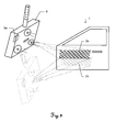
- FIGS. 3 and 4 show an inventive optical measuring system 7 with hand-held and IMU (with inertial sensors 5a), the projector 3 and a camera 4a exhibiting measuring head 8 (eg integrated in a hand-held housing with handle and thus designed as a light structures 3D hand scanner), with a car door as a measurement object 1 successively having different fineness patterns 2a, 2b as part of the pattern sequence; FIG. 3 : coarser pattern 2a; and FIG. 4 : fine structured pattern 2b) is illuminated.
- IMU with inertial sensors 5a
- measuring head 8 eg integrated in a hand-held housing with handle and thus designed as a light structures 3D hand scanner
- an illumination of the object takes place with a sequence of light patterns 2 a, 2 b of different structure fineness, to obtain a clear depth determination of the measuring points in the measuring range with the help of triangulation (forward cutting).
- image shots ie a series of images
- the measuring object 1 takes place with the corresponding different patterns 2a, 2b (ie with the series of patterns).
- an inertial measuring unit (with inertial sensors 5a) is inserted into the measuring head 8 of the in the FIGS. 3 and 4 integrates illustrated 3D scanner, whereby a compensation according to the invention can be done, for example, caused by hand tremor-induced disquieting measurement errors in the context of the evaluation of the image sequence and the derivation of the 3D coordinates.
- the illustrated optical measuring system 7 for performing one or more of the above-described embodiments of the inventive optical measuring method are designed and designed.
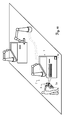
- FIGS. 5 and 6 is an inventive optical measuring system 7 similar to that from FIGS. 3 and 4 except that the measuring head 8 is embodied here as a robot arm-held measuring head 8 and the projector 3 is designed as a pattern sequence for successively projecting striations 2 a, 2 b having different finenesses.
- the measuring head 8 is embodied here as a robot arm-held measuring head 8 and the projector 3 is designed as a pattern sequence for successively projecting striations 2 a, 2 b having different finenesses.
- an inertial measuring unit IMU (with inertial sensors 5a), whereby a compensation according to the invention of measurement errors, for example, by transmitted to the robot arm from the measuring range environment Vibrations can be effected as part of the evaluation of the image sequence and the derivation of the 3D coordinates.
- the measured accelerations can also be used for spatially stitching individual frames acquired from different robot arm positions (as part of one or more image sequences), so that, depending on the choice of the different shot positions, these are adjusted as required by the person skilled in the art can be - thereby the measuring range can be increased and / or compressed, or changing a case of lighting with substantially coherent optical radiation unintentionally occurring Specklefeldern in the respective patterns 2a, 2b of the pattern sequence and thus reducing by such Specklefelder caused local measurement inaccuracies or measurement point gaps can be made.
- FIGS. 7 and 9 show a similar measuring system 7 as off FIG. 1 and illustrate thereby an (unintentionally Handtremor myselfes or - for example, for purposes of compressing or increasing the measuring range - intentional) Unruhighalten / moving the measuring head 8 during a measurement.
- the accelerations measured on the basis of the IMU can then be used for spatial stitching of the individual frames captured from different handheld positions (as part of one or more image sequences).
- a blurring of individual pattern projections 2 a, 2 b (a pattern sequence) on the measurement object 1 and a blurring of individual image recordings (an image sequence) can also be effected
- blurring errors in the image can likewise be corrected on the basis of the accelerations measured by the IMU integrated in the measuring head 8 or compensated or taken into account in the context of the 3D coordinate determination.
- FIG. 8 represents an optical measuring system 7 according to the invention with IMU (with inertial sensors 5b) arranged on the measuring object 1, whereby the measuring object 1 can be brought into different positions, for example, to increase the measuring range and, according to the invention, those recorded in the individual pictures (the picture sequence) different points of the measuring object 1 can be linked based on the IMU-measured accelerations and brought into spatial relation with each other.
- IMU with inertial sensors 5b
- an IMU (with inertial sensors 5a) can again be integrated in the measurement head 8 itself.
- movements of the measuring head 8 occurring during the measurement can, according to the invention, also be taken into account when determining the depth information and the 3D coordinates.
- FIG. 10 shows an optical measuring system 7 according to the invention in use in a production line, whereby the vibrations which are transmitted to measurements with the measuring system 7 according to the invention and which are transmitted from an adjacent production station are compensated on the basis of the measured accelerations.
- the pure here an IMU with inertial sensors 5a or 5b
- an inventive compensating of measuring errors caused, for example, by vibrations transmitted to the robot arm from the measuring range environment and by disquieting of the measuring head 8 is carried out as part of the evaluation the image sequence and the derivation of the 3D coordinates can be done.
Abstract
Description
Die Erfindung betrifft ein optisches Messverfahren zum Bestimmen von 3D-Koordinaten von einer Vielzahl von Messpunkten einer Messobjekt-Oberfläche nach dem Oberbegriff des Anspruchs 1 sowie ein zu selbigem Zweck ausgebildetes Messsystem nach dem Oberbegriff des Anspruchs 9.The invention relates to an optical measuring method for determining 3D coordinates of a plurality of measuring points of a measuring object surface according to the preamble of
Derartige Vorrichtungen und Verfahren werden insbesondere im Maschinenbau, Automobilbau, Keramikindustrie, Schuhindustrie, Schmuckindustrie, Dentaltechnik und Humanmedizin (Orthopädie) und weiteren Bereichen verwendet und kommen beispielsweise zum Einsatz für die Vermessung und Protokollierung für Qualitätskontrolle, Reverse Engineering, Rapid Prototyping, Rapid Milling oder Digital Mock-Up.Such devices and methods are used in particular in mechanical engineering, automotive industry, ceramics industry, shoe industry, jewelry industry, dental technology and human medicine (orthopedics) and other fields and are used, for example, for surveying and logging for quality control, reverse engineering, rapid prototyping, rapid milling or digital Mock-up.
Die steigenden Forderungen nach einer weitgehend vollständigen Qualitätskontrolle im laufenden Produktionsprozess sowie nach der Digitalisierung der Raumform von Prototypen machen die Aufnahme von Oberflächentopografien zu einer immer häufiger gestellten Messaufgabe. Dabei stellt sich die Aufgabe, die Koordinaten einzelner Punkte der Oberfläche der zu vermessenden Gegenstände in kurzer Zeit zu bestimmen.The increasing demands for a largely complete quality control in the ongoing production process as well as for the digitization of the spatial form of prototypes make the inclusion of surface topographies an increasingly frequent measuring task. This raises the task of determining the coordinates of individual points of the surface of the objects to be measured in a short time.
Aus dem Stand der Technik bekannte, Bild-Sequenzen verwendende Messsysteme zur Bestimmung von 3D-Koordinaten von Messobjekten, die beispielsweise als portable, handhaltbare und/oder fest installierte Systeme ausgebildet sein können, weisen dabei im Allgemeinen einen Musterprojektor zur Beleuchtung des Messobjekts mit einem Muster auf und werden daher teilweise auch als musterprojizierende 3D-Scanner oder Lichtstrukturen-3D-Scanner bezeichnet. Das auf die Oberfläche des Messobjekts projizierte Muster wird von einem Kamerasystem als weiterer Bestandteil des Messsystems aufgenommen.From the prior art, measuring systems using known image sequences for determining 3D coordinates of DUTs, which may be designed, for example, as portable, handheld and / or permanently installed systems, generally have a pattern projector for illuminating the DUT with a DUT Patterns are therefore sometimes referred to as pattern projecting 3D scanners or light pattern 3D scanners. The pattern projected onto the surface of the measurement object is recorded by a camera system as an additional component of the measurement system.
Im Rahmen einer Messung beleuchtet also der Projektor das Messobjekt zeitlich sequentiell mit unterschiedlichen Mustern (z.B. parallele helle und dunkle Streifen unterschiedlicher Breite, insbesondere kann auch eine Drehung des Streifenmusters z.B. um 90° erfolgen). Die Kamera(s) registrieren das projizierte Streifenmuster unter einem bekannten Blickwinkel zur Projektion. Für jedes Projektionsmuster wird mit jeder Kamera ein Bild aufgenommen. Für jeden Bildpunkt aller Kameras entsteht so eine zeitliche Folge von unterschiedlichen Helligkeitswerten.Thus, within the scope of a measurement, the projector illuminates the measurement object sequentially in time with different patterns (for example, parallel light and dark stripes of different widths, in particular, a rotation of the stripe pattern, for example by 90 °). The camera (s) register the projected fringe pattern at a known viewing angle. For each projection pattern, an image is taken with each camera. For each pixel of all cameras, a chronological sequence of different brightness values is created.
Projiziert werden können dabei ausser Streifen jedoch auch entsprechende andere Muster, wie beispielsweise Random Patterns, Pseudocodes, etc. Dafür geeignete Muster sind aus dem Stand der Technik dem Fachmann hinlänglich bekannt. Pseudocodes ermöglichen z.B. eine leichtere absolute Zuordnung von Objektpunkten, was bei der Projektion sehr feiner Streifen zunehmend schwieriger wird. Zu diesem Zweck kann also entweder in schneller Folge zunächst ein oder mehrere Pseudocodes und danach ein feines Streifenmuster oder auch in aufeinander folgenden Aufnahmen verschiedne, in der Abfolge feiner werdende Streifenmuster projiziert werden, bis die gewünschte Genauigkeit in der Auflösung von Messpunkten auf der Messobjekt-Oberfläche erreicht ist.However, in addition to strips, corresponding other patterns, such as random patterns, pseudocodes, etc., can also be projected. Suitable patterns for this purpose are well known to the person skilled in the art from the prior art. Pseudocodes allow e.g. a lighter absolute allocation of object points, which becomes increasingly difficult in the projection of very fine stripes. For this purpose, therefore, one or more pseudocodes and then a fine stripe pattern or in successive shots different, be projected in the sequence finer stripe pattern either in rapid succession until the desired accuracy in the resolution of measuring points on the measuring object surface is reached.
Die 3D-Koordinaten der Messobjekt-Oberfläche können dann aus der aufgenommenen Bild-Sequenz mittels Bildverarbeitung nach dem Fachmann auf diesem Gebiet bekannten Verfahren aus der Photogrammetrie und/oder Streifenprojektion berechnet werden. Beispielsweise sind derartige Messverfahren und Messsysteme beschrieben in der
Im Üblichen besteht das Kamerasystem aus einer oder mehreren digitalen Kameras, die sich während einer Messung in bekannter räumlicher Lage zueinander befinden. Zur Gewährleistung einer stabilen Lage der Kameras relativ zueinander sind diese meist fix mit bekannter räumlicher Positionierung und Ausrichtung zusammen in einem gemeinsamen Gehäuse integriert, insbesondere wobei die Kameras derart ausgerichtet sind, dass sich die Sichtfelder der einzelnen Kameras grösstenteils überschneiden. Oft werden dabei zwei oder drei Kameras verwendet. Der Projektor kann dabei fest mit dem Kamerasystem verbunden sein (im Falle der Verwendung von getrennten Kameras auch nur mit einem Teil der vorhandenen Kameras des Kamerasystems) oder auch komplett getrennt vom Kamerasystem positioniert werden.In the usual case, the camera system consists of one or more digital cameras, which are located in a known spatial position during a measurement. To ensure a stable position of the cameras relative to each other, these are usually integrated with a known spatial positioning and alignment together in a common housing, in particular wherein the cameras are aligned such that the fields of view of the individual cameras overlap for the most part. Often, two or three cameras are used. The projector can be firmly connected to the camera system (in the case of the use of separate cameras with only a part of the existing cameras of the camera system) or be positioned completely separate from the camera system.
Die gesuchten dreidimensionalen Koordinaten der Oberfläche werden im allgemeinen Fall, d.h. im Fall dass relative Positionierung und Ausrichtung von Projektor zum Kamerasystem fix zueinander und daher nicht vorab schon bekannt ist, in zwei Schritten berechnet. In einem ersten Schritt werden dann die Koordinaten des Projektors wie folgt bestimmt. Zu einem gegebenen Objektpunkt sind die Bildkoordinaten im Kamerabild bekannt. Der Projektor entspricht einer umgekehrten Kamera. Aus der Folge von Helligkeitswerten, die aus der Bildsequenz für jeden Kamerabildpunkt gemessen wurden, kann die Nummer des Streifens berechnet werden. Im einfachsten Fall erfolgt das über einen Binärkode (z.B. einen Gray-Code) der die Nummer des Streifens als diskrete Koordinate im Projektor kennzeichnet. Eine höhere Genauigkeit ist mit dem so genannten Phasenschiebeverfahren zu erreichen, da es eine nicht diskrete Koordinate bestimmen kann. Es kann entweder als Ergänzung eines Gray-Codes oder als absolut messendes Heterodynverfahren eingesetzt werden.The sought three-dimensional coordinates of the surface are calculated in the general case, ie in the case that relative positioning and orientation of the projector to the camera system fixed to each other and therefore not previously known, in two steps. In a first step, the coordinates of the projector are determined as follows. For a given object point, the image coordinates in the camera image are known. The projector is equivalent to a reversed camera. From the sequence of brightness values measured from the image sequence for each camera pixel, the number of the Be calculated. In the simplest case, this is done via a binary code (eg a Gray code) which identifies the number of the strip as a discrete coordinate in the projector. A higher accuracy can be achieved with the so-called phase shift method, since it can determine a non-discrete coordinate. It can be used either as a supplement to a Gray code or as an absolute heterodyne method.
Nach solcherart bestimmter Position des Projektors oder bei bereits vorab bekannter Position desselben relativ zum Kamerasystem können nun - z.B. durch die Methode des Vorwärtsschnitts - wie folgt 3D-Koordinaten von Messpunkten auf der Messobjekt-Oberfläche ermittelt werden. Die Streifennummer im Projektor entspricht der Bildkoordinate in der Kamera. Die Streifennummer spezifiziert eine Lichtebene im Raum, die Bildkoordinate einen Lichtstrahl. Bei bekannter Kamera und Projektorposition kann der Schnittpunkt der Ebene und der Gerade berechnet werden. Das ist die gesuchte dreidimensionale Koordinate des Objektpunktes im Koordinatensystem des Sensors. Die geometrische Lage aller Bildstrahlen muss genau bekannt sein. Die exakte Berechnung der Strahlen erfolgt mit dem aus der Photogrammetrie bekannten Vorwärtsschnitt.After such a certain position of the projector or at a previously known position thereof relative to the camera system can now -. by the method of forward cutting - as follows 3D coordinates of measuring points on the measuring object surface are determined. The stripe number in the projector corresponds to the image coordinate in the camera. The strip number specifies a light plane in space, the image coordinate specifies a light beam. If the camera and projector position are known, the intersection of the plane and the line can be calculated. This is the searched three-dimensional coordinate of the object point in the coordinate system of the sensor. The geometric position of all image rays must be known exactly. The exact calculation of the beams takes place with the forward cut known from photogrammetry.
Zur Erzielung von höheren Genauigkeiten bei diesem Messverfahren für die Berechnung der 3D-Koordinaten können die nicht idealen Eigenschaften von realen Linsensystemen, die in Verzerrungen des Bildes resultieren, durch eine Verzeichnungskorrektur angepasst werden und/oder eine präzise Kalibrierung der Abbildungseigenschaften erfolgen. Alle Abbildungseigenschaften von Projektor und Kameras können dabei im Rahmen von dem Fachmann bekannten Kalibrierungsprozessen (z.B. einer Serie von Kalibrieraufnahmen) gemessen und daraus ein mathematisches Modell zur Beschreibung dieser Abbildungseigenschaften generiert werden (z.B. werden aus der Serie von Kalibrieraufnahmen mit photogrammetrischen Methoden - insbesondere mit einer Bündelausgleichsrechnung - die die Abbildungseigenschaften bezeichnende Parameter bestimmt).To achieve higher accuracies in this measurement method for the calculation of the 3D coordinates, the non-ideal properties of real lens systems, which result in distortions of the image, can be adjusted by a distortion correction and / or a precise calibration of the imaging properties. All imaging properties of the projector and cameras can be determined within the scope of calibration processes known to the person skilled in the art (eg a series of Calibration recordings) and from this a mathematical model for the description of these imaging properties is generated (eg the series of calibration recordings with photogrammetric methods - in particular with a bundle compensation calculation - determines the parameters characterizing the imaging properties).
Zusammengefasst ist also bei dem Musterprojektionsverfahren bzw. bei Lichtstrukturen-3D-Scanner eine Beleuchtung des Objekts mit einer Sequenz von Lichtmustern erforderlich, um eine eindeutige Tiefenbestimmung der Messpunkte im Messbereich mit Hilfe von Triangulation (Vorwärtsschnitt) zu ermöglichen. Es sind also meist mehrere Aufnahmen (d.h. eine Serie von Bildern) unter Beleuchtung des Messobjekts mit entsprechenden unterschiedlichen Muster-Projektionen (d.h. mit einer entsprechenden Serie von Mustern) notwendig, um eine hinlänglich hohe Genauigkeit bezüglich des Messergebnisses zu gewährleisten. Bei aus dem Stand der Technik bekannten handgehaltenen Systemen, wie beispielsweise bei der in der
Für einen Messvorgang mit Projizieren einer Serie von Patterns und Aufnehmen einer Bild-Sequenz der jeweiligen Patterns mit dem Kamerasystem ist mit herkömmlichen Messvorrichtungen z.B. eine Messdauer von etwa 200 ms nötig (als Beispiel: für die Aufnahme von Sequenzen von 8 bis 10 Bildern bei einer Belichtungsdauer 20 ms bis 40 ms pro Bild können sich z.B. Gesamtaufnahmezeiten bzw. Messdauern von zwischen 160 ms und 400 ms pro Messposition ergeben).For a measuring operation with projecting a series of patterns and taking an image sequence of the respective patterns with the camera system, it is possible with conventional measuring devices e.g. a measurement duration of about 200 ms is necessary (for example: for the acquisition of sequences of 8 to 10 images at an exposure time of 20 ms to 40 ms per image, total acquisition times of between 160 ms and 400 ms per measurement position may result).
Bei nicht hinlänglichem Ruhighalten bzw. bei nicht hinlänglich hoher Positions- und Ausrichtungshaltigkeit der Kameraanordnung, des Projektors (bzw. ggf. eines die Kameraanordnung und den Projektor integriert beinhaltenden Messkopfes) und des Messobjekts relativ zueinander während eines Messvorgangs (in einer Messposition) kann es somit zu verschiedenen unerwünschten und die Auswertung erschwerenden, verkomplizierenden, gar verunmöglichenden oder zumindest die erzielbare Genauigkeit negativ beeinflussenden Effekten kommen.If the camera arrangement, the projector (or possibly a measuring head integrated with the camera arrangement and the projector) and the object to be measured relative to one another during a measuring process (in a measuring position) are not sufficiently stable or if the camera arrangement and orientation are not sufficiently high to various undesirable and the evaluation aggravating, complicating, even impossible or at least the achievable accuracy negatively affecting effects come.
Für ein unzulängliches Nichtruhighalten der Kameraanordnung, des Projektors (bzw. ggf. eines die Kameraanordnung und den Projektor integriert beinhaltenden Messkopfes) oder des Messobjekts können dabei unterschiedliche Ursachen infrage kommen.For inadequate non-restraining of the camera arrangement, the projector (or, if necessary, a measuring head integrated with the camera arrangement and the projector) or the measurement object, different causes can be considered.
Zum einen können Vibrationen in der Messumgebung (z.B. falls die Messungen an einer in eine Produktionsstrasse integrierten Produktionsstation durchgeführt werden) auf die Halterung des Messobjekts oder auch einen den Messkopf haltenden Roboterarm übertragen werden und somit zu störenden Schwingungen führen. Daher sind bisher aufwändige Massnahmen zur Schwingungsdämpfung nötig oder es ist ein Ausweichen auf spezielle Messräume erforderlich, was jedoch den Produktionsprozess deutlich aufwändiger gestaltet (da ein Entnehmen des Messobjekts aus der Produktionsstrasse und ein Transportieren desselben in den entsprechend dafür ausgelegten Messraum erforderlich ist).On the one hand, vibrations in the measuring environment (eg if the measurements are carried out on a production station integrated in a production line) can occur the holder of the test object or a robot arm holding the measuring head are transmitted and thus lead to disturbing vibrations. Therefore, hitherto elaborate measures for vibration damping are necessary or it is necessary to escape to special measuring rooms, but this makes the production process significantly more complex (since a removal of the measurement object from the production line and transporting the same is required in the corresponding designed measuring space).
Bei handgehaltenen Systemen ist die Hauptursache für unzulängliches Nichtruhighalten insbesondere der natürliche Tremor in der Hand des menschlichen Benutzers.In hand-held systems, the main cause of inadequate non-restraint is, in particular, the natural tremor in the hand of the human user.
Als negative Effekte, die durch mangelnde Positions- und Ausrichtungshaltigkeit der Kameraanordnung, des Projektors und des Messobjekts relativ zueinander bewirkt werden können, sind - zum einen - eine Bewegungsunschärfe und/oder Verwacklungen in einzelnen aufgenommenen Bildern einer Bild-Sequenz zu nennen.As negative effects that can be caused by lack of position and Ausrichtungshaltigkeit the camera assembly, the projector and the measuring object relative to each other, are - on the one - a motion blur and / or camera shake in individual recorded images of an image sequence to call.
Zum anderen können jedoch auch Unkonformitäten der einzelnen Bilder einer Bild-Sequenz zueinander bezüglich deren jeweiligen Aufnahmepositionen und -richtungen relativ zum Messobjekt (d.h. Schwankungen in den Aufnahmepositionen und -richtungen bei den einzelnen Bildern innerhalb einer Bild-Sequenz) auftreten, sodass ein jeweiliges Zuordnen von Bildpunkten in den einzelnen Bildern zu identischen Messpunkten auf der Messobjekt-Oberfläche entweder ganz verunmöglicht ist oder nur durch enorm hohen Rechenaufwand und Miteinbeziehen von Informationen aus einer Vielzahl von Bildern desselben Bereichs der Messobjekt-Oberfläche ermöglicht werden kann (d.h. es kann ein sich sehr aufwändig gestaltendes nachträgliches rechnerisches in räumlichen Bezug Bringen der Einzelbilder erforderlich sein, weshalb bisher teilweise präventiv gegen diesen Effekt ein Überschuss an Bildern pro Bild-Sequenz aufgenommen werden, die hauptsächlich lediglich zum Rückrechnen des räumlichen Bezugs der Aufnahmepositionen und -richtungen der einzelnen Bilder untereinander dienen).On the other hand, however, also inconsistencies of the individual images of an image sequence relative to one another with regard to their respective recording positions and directions relative to the measurement object (ie fluctuations in the recording positions and directions in the individual images within an image sequence) can occur, so that a respective assignment of Pixels in the individual images to identical measuring points on the measuring object surface is either completely impossible or can be made possible only by enormously high computational effort and involving information from a variety of images of the same area of the measuring object surface (ie it can be a very aufwändig gestaltendes subsequent arithmetic in spatial reference to bring the individual images are required, which is why so far been partially taken preventively against this effect, an excess of images per image sequence, which are mainly only for calculating back the spatial reference of the recording positions and directions of the individual images with each other).
Zur Erweiterung des Messbereichs auf dem Messobjekt (z.B. zur Vermessung eines Objekts in seiner Gesamtheit), sind oft mehrere Messungen nacheinander (aus verschiedenen Messpositionen und unter verschiedenen Blickwinkeln der Kameras relativ zum Messobjekt) erforderlich, wobei die Ergebnisse der verschiedenen Messungen anschliessend miteinander verknüpft werden. Dies kann beispielsweise dadurch erfolgen, dass bei den jeweiligen Messvorgängen die Erfassungsbereiche jeweils überlappend gewählt werden und der jeweilige Überlapp zum entsprechenden Zusammenfügen der bei mehreren Messvorgängen gewonnenen 3D-Koordinaten (d.h. Punktwolken) verwendet wird (d.h. es können identische oder ähnliche Verteilungen in den bei den einzelnen Messvorgängen bestimmten Punktwolken identifiziert und dementsprechend die Punktwolken zusammengefügt werden).To extend the measurement area on the measurement object (for example, to measure an object in its entirety), multiple measurements are often required in succession (from different measurement positions and from different angles of the cameras relative to the measurement object), with the results of the various measurements subsequently being linked together. This can be done, for example, by selecting the coverage areas in overlapping fashion during the respective measurement processes and by using the respective overlap for correspondingly combining the 3D coordinates (ie point clouds) obtained during several measurement processes (ie identical or similar distributions in the case of the individual measurement processes identified specific point clouds and accordingly the point clouds are joined together).
Dieser Zusammenfügungsvorgang ist im Allgemeinen jedoch extrem rechenintensiv und bedarf sogar bei Verfügbarkeit von höchsten Prozessorleistungen dennoch einen nicht zu verachtenden und störend hohen Zeit- und Energieaufwand. Bei Verwendung z.B. eines Roboterarms zum Halten und Führen des Messkopfes kann etwa dadurch eine Reduzierung des für den Zusammenfügungsvorgang erforderlichen Rechenaufwands erreicht werden, indem die Aufnahmepositionen und - richtungen bei den einzelnen Messungen anhand der jeweiligen Roboterarmstellung erfasst und diese für das Zusammenfügen als Vorinformation (z.B. als Randbedingungen) herangezogen werden.However, this assembly process is generally extremely computationally intensive and still requires a great deal of time and energy, even with the highest processor performance available. By using, for example, a robot arm for holding and guiding the measuring head, a reduction in the computation required for the joining process can be achieved by detecting the positions and directions of the individual measurements on the basis of the respective robot arm position and for pre-information (eg Boundary conditions) be used.
Nachteile hierbei sind die verhältnismässig geringe Genauigkeit mit welcher anhand der Roboterarmstellung die Messposition bestimmbar ist und - gleichwohl - das Erfordernis des Vorhandenseins eines solchen Roboterarms. So kann die Rechenleistung, die für das Zusammenfügen von Messergebnissen mehrerer Messvorgänge erforderlich ist, für handgehaltene Messsysteme nicht auf diese Weise reduziert werden.Disadvantages here are the relatively low accuracy with which the measuring position can be determined on the basis of the robot arm position and - nevertheless - the requirement for the presence of such a robot arm. For example, the computing power required to combine measurement results from multiple measurements can not be reduced in this way for handheld measurement systems.
Weiterer Nachteile von Systemen des Standes der Technik, welche zur Musterbeleuchtung im Wesentlichen kohärente optische Strahlung verwenden, sind - durch ungewollt auftretende Specklefelder in den jeweiligen Mustern der Muster-Sequenz hervorgerufene - lokale Messungenauigkeiten oder Messpunkt-Lücken.Further disadvantages of prior art systems which use substantially coherent optical radiation for pattern illumination are local inaccuracies or measurement point gaps caused by unwanted speckle fields in the respective patterns of the pattern sequence.
Die der Erfindung zugrunde liegende technische Aufgabe ist daher das Bereitstellen eines verbesserten, Bild-Sequenzen verwendenden optischen Messverfahrens und Messsystems zum Bestimmen von 3D-Koordinaten auf einer Messobjekt-Oberfläche, insbesondere wobei ein oder mehrere der zuvor beschriebenen Nachteile vermindert oder behoben werden können.The technical problem underlying the invention is therefore to provide an improved optical measuring method and measuring system using image sequences for determining 3D coordinates on a measuring object surface, in particular wherein one or more of the disadvantages described above can be reduced or eliminated.
Spezifischere Aufgaben der Erfindung sind dabei das Ermöglichen einer präziseren Bestimmung von 3D-Koordinaten auch bei für aus dem Stand der Technik bekannte Messsysteme unzulänglicher Positionshaltigkeit des Projektors, des Kamerasystems und/oder des Messobjekts (z.B. durch unerwünschte Schwingungen, Vibrationen oder Unruhighalten) während des Messvorgangs (d.h. während des Mustersequenzprojizierens und der Bildsequenzaufnahme). Im Speziellen sollen dabei - zum einen - auf Verwackelungen und/oder Bewegungsunschärfen in den Einzelbildern einer Bild-Sequenz zurückzuführende Fehler oder Ungenauigkeiten in der Bestimmung der 3D-Koordinaten verringert werden können. Zum anderen sollen auch Fehler verringert oder eliminiert werden können, die auf bei Unruhighalten auftretenden Aufnahmepositions- und -richtungsschwankungen bei den Bildern einer Bild-Sequenz untereinander zurückzuführen sind.More specific objects of the invention are thereby enabling a more precise determination of 3D coordinates even in measurement systems known from the prior art insufficient positional stability of the projector, the camera system and / or the measurement object (eg by unwanted vibration, vibration or Vorruhighalten) during the measurement process (ie, during pattern sequence projecting and image sequence recording). in the Specifically, on the one hand, errors or inaccuracies in the determination of the 3D coordinates attributable to shaking and / or motion blur in the individual images of an image sequence should be able to be reduced. On the other hand, it is also intended to be able to reduce or eliminate errors attributable to exposure position and direction fluctuations in the images of an image sequence which occur during unrest.
Eine weitere spezifische Aufgabe bei Verwendung einer kohärenten Quelle zum Projizieren der Muster ist das Verringern der durch auftretende Speckle im Muster auf der Messobjekt-Oberfläche hervorgerufenen lokalen Messlücken oder lokalen Messungenauigkeiten.Another specific task when using a coherent source to project the patterns is to reduce the local gauges or local measurement inaccuracies caused by speckle occurring in the pattern on the DUT surface.
Eine weitere spezifische Aufgabe - besonders für handgehaltene Messsysteme - ist das Vereinfachen des Zusammenfügens von Messergebnissen (z.B. daraus erzeugten Punktwolken) mehrerer Messvorgänge und/oder das Ermöglichen einer Reduzierung der für ein solches Zusammenfügen erforderlichen Rechenleistung.Another specific task - especially for hand-held measurement systems - is to simplify the aggregation of measurement results (e.g., point clouds generated therefrom) of multiple measurement operations and / or to allow a reduction in the computational power required for such assembly.
Diese Aufgaben werden durch die Verwirklichung der kennzeichnenden Merkmale der unabhängigen Ansprüche gelöst. Merkmale, die die Erfindung in alternativer oder vorteilhafter Weise weiterbilden, sind den abhängigen Patentansprüchen zu entnehmen.These objects are achieved by the realization of the characterizing features of the independent claims. Features which further develop the invention in an alternative or advantageous manner can be found in the dependent claims.
Die Erfindung betrifft ein musterprojizierendes und Bild-Sequenzen verwendendes Messverfahren zum Bestimmen von 3D-Koordinaten einer Messobjekt-Oberfläche sowie ein zu selbigem Zweck ausgebildetes Messsystem.The invention relates to a pattern projecting and image sequences using measuring method for determining 3D coordinates of a measuring object surface and a measuring system designed for the same purpose.
Im Rahmen der Erfindung werden dabei während eines Messvorgangs - d.h. beim Aufnehmen der Bild-Sequenz - anhand von Inertialsensoren translatorische und/oder rotatorische Beschleunigungen des Musterprojektors, des Kamerasystems (bzw. ggf. eines die Kameraanordnung und den Projektor integriert beinhaltenden Messkopfes) und/oder des Messobjekts gemessen und die gemessenen Beschleunigungen beim Bestimmen der 3D-Koordinaten berücksichtigt.In the context of the invention are doing during a Measuring process - ie when recording the image sequence - using inertial sensors translational and / or rotational accelerations of the pattern projector, the camera system (or possibly a camera assembly and the projector integrated containing the measuring head included) and / or measured object measured and the measured accelerations at Determining the 3D coordinates considered.
Dafür können am Kamerasystem, am Projektor und/oder am Messobjekt die Inertialsensoren angeordnet sein, wobei die Inertialsensoren insbesondere zusammen als integrierte inertiale Messeinheit ausgebildet sind.For this, the inertial sensors can be arranged on the camera system, on the projector and / or on the measurement object, the inertial sensors in particular being designed together as an integrated inertial measurement unit.
Je nach Ausführungsvariante des Kamerasystems und des Projektors können die Inertialsensoren dabei entsprechend in einem Komponenten des Kamerasystems und/oder des Projektors beinhaltenden Gehäuse mitintegriert sein. Das Kamerasystem (auch Kameraanordnung genannt) kann beispielsweise - wie aus dem Stand der Technik bereits bekannt - aus einer, zwei, drei, vier oder mehr Kameras aufgebaut sein, die mit fixer und bekannter Positionierung und Orientierung relativ zueinander in einem gemeinsamen Gehäuse angeordnet und zur im Wesentlichen simultan erfolgenden Aufnahme von Einzelbildern ausgebildet sind. Alternativ können einzelne Kameras der Kameraanordnung auch körperlich separat voneinander mit jeweils eigenem Gehäuse ausgeführt sein, was im Allgemeinen die Auswertung der Bild-Sequenzen jedoch erschwert, da dann der relative räumliche Bezug der Kameras zueinander nicht vordefiniert ist (wodurch sich im Normalfall ein erhöhter Rechenaufwand bei der Auswertung der Bild-Sequenzen ergibt). Zudem tritt im Fall von körperlich separat ausgeführten Kameras bei handgehaltenen Systemen die Benutzungserschwernis auf, mehrere separate Gerätschaften tragen und halten zu müssen.Depending on the embodiment variant of the camera system and the projector, the inertial sensors may be integrated in a housing correspondingly contained in a component of the camera system and / or the projector. The camera system (also called camera arrangement) can be constructed, for example-as already known from the prior art-from one, two, three, four or more cameras, which are arranged with fixed and known positioning and orientation relative to one another in a common housing and for formed substantially simultaneously taking pictures of individual images. Alternatively, individual cameras of the camera arrangement can also be carried out physically separately from one another with their own housing, which generally complicates the evaluation of the image sequences, since then the relative spatial relationship of the cameras to each other is not predefined (which normally results in an increased amount of computation the evaluation of the image sequences results). In addition, in the case of physically separate cameras in hand-held systems, the user's difficulty arises in having to carry and hold several separate devices.
Aus diesen beiden Gründen kann - insbesondere bei handhaltbaren oder zum Anbringen an einen Roboterarm ausgebildeten Systemen - das Kamerasystem zusammen mit dem Projektor mit fixer und bekannter Positionierung und Orientierung relativ zueinander körperlich in einem gemeinsamen Messkopf des Messsystems untergebracht sein, in dem dann auch erfindungsgemäss die Inertialsensoren bzw. die inertiale Messeinheit angeordnet sein kann.For these two reasons, the camera system together with the projector with fixed and known positioning and orientation relative to each other can physically be housed in a common measuring head of the measuring system, in particular in the case of hand-held or systems adapted for attachment to a robot arm, in which then the inertial sensors or the inertial measuring unit can be arranged.
Ebenso kann - alternativ oder zusätzlich - eine Gruppe von Inertialsensoren auch zum Anbringen an das zu vermessende Objekt ausgebildet sein, welche die gemessenen Beschleunigungen (oder bereits daraus abgeleitete Bewegungen oder gar Positionen und Ausrichtungen) an die Auswertereinheit des Messsystems zur Berücksichtigung bei der 3D-Koordiantenbestimmung kommuniziert.Likewise, alternatively or additionally, a group of inertial sensors can also be designed for attachment to the object to be measured, which measures the measured accelerations (or already derived movements or even positions and orientations) to the evaluation unit of the measuring system for consideration in the 3D coordinate determination communicated.
Im Speziellen sind dabei die Inertialsensoren in einer auf MEMS-basierten Komponenten beruhenden inertialen Messeinheit (wobei MEMS für Micro-Electro-Mechanical System steht) derart kombiniert und integriert, dass die inertiale Messeinheit zur Messung der Beschleunigungen in allen sechs Freiheitsgraden ausgebildet ist, insbesondere mit einer Messrate zwischen etwa 1 und 2000 Hz, im Speziellen zwischen etwa 50 und 2000 Hz.In particular, the inertial sensors in an inertial measuring unit based on MEMS-based components (where MEMS stands for Micro-Electro-Mechanical System) are combined and integrated in such a way that the inertial measuring unit is designed to measure the accelerations in all six degrees of freedom, in particular with a measuring rate between about 1 and 2000 Hz, in particular between about 50 and 2000 Hz.
Wie dem Fachmann bekannt können dabei durch die entsprechende Kombination mehrerer Inertialsensoren in einer inertialen Messeinheiten (engl.: Inertial Measurement Unit (IMU)) die Beschleunigungen der sechs Freiheiten in der Regel anhand der folgenden Sensorarten gemessen werden:As is known to the person skilled in the art, the accelerations of the six freedoms can generally be measured by the following combination of sensors by the corresponding combination of several inertial sensors in an inertial measurement unit (English: Inertial Measurement Unit (IMU)):
Drei orthogonal angeordnete Beschleunigungssensoren (auch als Translationssensoren bezeichnet) detektieren die lineare Beschleunigung in x- bzw. y- bzw. z-Achse. Daraus kann die translatorische Bewegung (sowie die relative Position) berechnet werden. Drei orthogonal angeordnete Drehratensensoren (auch als Gyroskopische Sensoren bezeichnet) messen die Winkelbeschleunigung um die x- bzw. y- bzw. z-Achse. Daraus kann die Rotationsbewegung (sowie die relative Ausrichtung) berechnet werden.Three orthogonally arranged acceleration sensors (also referred to as translational sensors) detect the linear acceleration in x, y or z axis. From this the translatory movement (as well as the relative position) can be calculated. Three orthogonally arranged yaw rate sensors (also called gyroscopic sensors) measure the angular acceleration about the x, y and z axes, respectively. From this, the rotational movement (as well as the relative orientation) can be calculated.
Derartige auf MEMS-basierte Komponenten beruhende inertiale Messeinheiten, die als miniaturisierte Geräte oder Baugruppen ausgebildet sind, sind aus dem Stand der Technik bereits hinlänglich bekannt und werden schon lange in Grossserie gefertigt.Such based on MEMS-based components inertial measurement units that are designed as miniaturized devices or assemblies are already well known in the art and have long been mass produced.
Die während eines Messvorgangs - oder zusätzlich auch zwischen mehreren Messvorgängen - erfassten Beschleunigungen des Kamerasystems, des Projektors und/oder des Messobjekts können erfindungsgemäss im Rahmen der Auswertung (z.B. im Rahmen des Bestimmens der 3D-Koordinaten der Messpunkte aus der Bild-Sequenz oder im Rahmen der Zusammenfügung von aus mehreren durchgeführten Messvorgängen gewonnenen Messergebnissen, d.h. aus mehreren Bild-Sequenzen) dabei für verschiedene Zwecke und zur Verbesserung unterschiedlicher Aspekte verwendet werden.The accelerations of the camera system, of the projector and / or of the measurement object detected during a measurement process-or in addition also between several measurement processes-can, according to the invention, be evaluated within the context of the evaluation of the 3D coordinates of the measurement points from the image sequence or within the frame the combination of measurement results obtained from a plurality of measuring operations performed, ie from several image sequences) thereby used for different purposes and to improve different aspects.
Werden während der Belichtungszeiten der einzelnen Bilder einer Bild-Sequenz die Beschleunigungen mit hinreichend hoher Rate (d.h. einer Rate, die zumindest einige - z.B. zwischen 5 und 50 - Beschleunigungswerte pro Belichtungsdauer eines Einzelbildes liefert), können Verwacklungen und/oder Bewegungsunschärfe im Bild provozierende Bewegungen des Projektors, des Kamerasystems und/oder des Messobjekts während der Belichtungszeiten der einzelnen Bilder der Bild-Sequenz anhand dieser gemessener Beschleunigungswerte algorithmisch berücksichtigt werden. Vorzugsweise können die gemessenen Beschleunigungswerte - nach z.B. aus der Photographie hinlänglich bekannten Verfahren - zum Kompensieren oder Korrigieren von Verwacklungen und/oder Bewegungsunschärfen in den einzelnen Bildern einer Bild-Sequenz verwendet werden.If during the exposure times of the individual images of an image sequence, the accelerations at a sufficiently high rate (ie, a rate that provides at least some - eg between 5 and 50 - acceleration values per exposure time of a frame), blurring and / or motion blur in the image provoking movements of the projector, the camera system and / or the measurement object during the exposure times of the individual images of the image sequence on the basis of these measured Acceleration values are taken into account algorithmically. Preferably, the measured acceleration values may be used to compensate for or correct for camera shake and / or motion blur in the individual images of an image sequence, for example, according to methods well known in photography.
Mangelnde Positions- und Orientierungshaltigkeit von Messsystem und Messobjekt relativ zueinander während der Belichtungszeiten der Bilder kann dabei hervorgerufen werden z.B. durch einen den Projektor, das Kamerasystem und/oder das Messobjekt handhaltenden Benutzer, insbesondere handtremorbedingt und unabsichtlich, oder durch Vibrationen oder Schwingungen in den Halterungen des Projektors, des Kamerasystems und/oder des Messobjekts.Lack of position and orientation of the measuring system and the measuring object relative to each other during the exposure times of the images can be caused thereby e.g. by a user holding the projector, the camera system and / or the measurement object, in particular by hand tremors and unintentionally, or by vibrations or oscillations in the holders of the projector, the camera system and / or the measurement object.
Die erfindungsgemäss erfasste Bewegung im Raum kann also z.B. zur Korrektur von Unschärfen in den einzelnen Aufnahmen von Digitalkameras bzw. Triangulationsscannern verwendet werden. Ausserdem können bei handgehaltenen Messsystemen die durch den Tremor der Hand eines Benutzers gegebenen prinzipiellen Limitierungen aufgehoben oder zumindest vermindert werden.The movement in space detected according to the invention can therefore be e.g. to correct for blurring in each shot taken by digital cameras or triangulation scanners. In addition, in hand-held measuring systems, the fundamental limitations given by the tremor of a user's hand can be eliminated or at least reduced.
Auch die bei einer stationären Installation des Messsystems oft auftretenden störenden Schwingungen/Vibrationen während Messungen können somit erfindungsgemäss - wie oben beschrieben - bei der Auswertung und beim Bestimmen der 3D-Koordinaten berücksichtigt werden. Dadurch kann z.B. auf oft baulich sehr aufwändige Vorkehrung zur Schwingungsdämpfung verzichtet werden (oder zumindest deutlich weniger aufwändige Verkehrungen vorgesehen werden), bei gleichzeitig verbesserter Genauigkeit bei der 3D-Koordinatenbestimmung oder zumindest ohne dabei Einbussen hinsichtlich der Genauigkeit hinnehmen zu müssen. Das erfindungsgemässe Messsystem eignet sich somit verbessert zum Einsatz direkt in einer Produktionslinie. Auf ein - insgesamt betrachtet - sehr aufwändiges Betreiben des Messsystems "offline" in einem speziellen Messraum (mit Entnehmen des Messobjekts aus der Produktionsstrasse und Transportieren desselben in den entsprechend dafür ausgelegten Messraum) kann - ermöglicht durch die Erfindung - im Allgemeinen verzichtet werden.The interfering oscillations / vibrations during measurements, which often occur in a stationary installation of the measuring system, can thus also be taken into account in the evaluation and in the determination of the 3D coordinates, as described above. As a result, it is possible, for example, to dispense with often structurally very costly provisions for vibration damping (or at least significantly less complex reversals can be provided), while at the same time improving accuracy in the 3D coordinate determination or at least without sacrificing it in terms of accuracy. The measuring system according to the invention is therefore more suitable for use directly in a production line. On a - considered overall - very complex operation of the measuring system "offline" in a special measuring room (with removal of the measurement object from the production line and transporting the same in the appropriately designed measuring space) - can be dispensed with - enabled by the invention in general.
Gemäss einer Weiterbildung können die erfassten Beschleunigungen von Messsystem-Komponenten (d.h. Kameraanordnung/Projektor) und/oder des Messobjekts erfindungsgemäss auch dafür verwendet werden, um den jeweiligen Bildern einer Bild-Sequenz jeweils eine zum jeweiligen Aufnahmezeitpunkt aktuelle Bildaufnahmeposition und -richtung relativ zum Messobjekt zuzuordnen. Dafür werden während eines gesamten Messvorgangs (d.h. des gesamten Vorgangs des Aufnehmens einer Bild-Sequenz oder auch mehrerer Bild-Sequenzen) die Beschleunigungen erfasst. Insbesondere können dazu die Beschleunigungen mit einer derartigen Rate gemessen werden, dass eine hinlänglich genaue Zuordnung zu den jeweiligen Aufnahmezeitpunkten der einzelnen Bilder ermöglicht ist. Werden die Beschleunigungen mit einer deutlich höheren Rate erfasst als die Bilder sequentiell aufgenommen werden, können den jeweiligen Bildern auch jene Bildaufnahmepositionen und -richtungen zugeordnet werden, die sich aus einer Mittelung der während den Belichtungsdauern der einzelnen Bildern erfassten Beschleunigungen ergeben.According to a further development, the detected accelerations of measuring system components (ie camera arrangement / projector) and / or the test object can also be used to associate the respective images of an image sequence with an image acquisition position and direction current relative to the measurement object , For this, the accelerations are detected during an entire measuring operation (i.e., the entire process of taking a picture sequence or even several picture sequences). In particular, the accelerations can be measured at a rate such that a sufficiently accurate assignment to the respective recording times of the individual images is made possible. If the accelerations are recorded at a significantly higher rate than the images are acquired sequentially, the respective images can also be assigned those image acquisition positions and directions which result from an averaging of the accelerations detected during the exposure times of the individual images.
Die den einzelnen Bildern einer Bild-Sequenz zugeordneten jeweiligen Aufnahmepositionen und -richtungen zum vereinfachten Verknüpfen von Bildpunkten in den einzelnen Bildern zu identischen Messpunkten auf der Messobjekt-Oberfläche, auch im Falle dass - z.B. tremorbedingt - Schwankungen in den Aufnahmepositionen und -richtungen der einzelnen Bildern innerhalb einer Bild-Sequenz auftreten.The respective recording positions and directions assigned to the individual pictures of an image sequence for the simplified linking of picture elements in the individual Images at identical measuring points on the measuring object surface, even in the event that - for example due to tremor - fluctuations in the recording positions and directions of the individual images occur within an image sequence.
Der Rechenaufwand für die Auswertung einer Bild-Sequenz (der insbesondere für das Vorwärtsschnittverfahren erforderlich ist) kann erfindungsgemäss somit also deutlich reduziert werden, da abgeleitet von den Aufnahmepositionen und -richtungen vorab bestimmt werden kann, durch welche Bildpunkte in den jeweiligen Bildern der Bild-Sequenz jeweils identische Messpunkte der Oberfläche abgebildet sind.The computational outlay for the evaluation of an image sequence (which is necessary in particular for the forward cutting method) can therefore be significantly reduced according to the invention, since it can be determined in advance, by means of which pixels in the respective images of the image sequence, that the acquisition positions and directions can be determined identical measuring points of the surface are shown.
Da bei Systemen aus dem Stand der Technik bisher teilweise ein Überschuss an Bildern pro Bild-Sequenz aufgenommen werden musste, um - vor der eigentlichen Auswertung - die Bilder zueinander durch Bildverarbeitung miteinander in einen räumlichen Bezug zu bringen, kann erfindungsgemäss nun der Rechenaufwand und/oder die erforderliche Anzahl von aufzunehmenden Bildern pro Bild-Sequenz für das vergleichbar genaue Bestimmen der 3D-Koordinaten aus dieser Bild-Sequenz reduziert werden.Since in systems of the prior art so far, an excess of images per image sequence had to be recorded in order - before the actual evaluation - the images to each other by image processing in a spatial reference, according to the invention now the computational effort and / or the required number of pictures to be taken per picture sequence can be reduced for the comparably accurate determination of the 3D coordinates from this picture sequence.
Auf der anderen Seite wird durch die Erfindung jedoch nun auch ermöglicht, über längere Messzeiträume Bilder einer Bild-Sequenz aufzunehmen, da der Einfluss durch ein Nichtruhighalten von Messkomponenten während des Aufnehmens der Serie von Bildern erfindungsgemäss hinlänglich gut kompensierbar oder korrigierbar ist und nicht zu Messausfällen führt.On the other hand, however, the invention now also makes it possible to record images of an image sequence over longer measurement periods, since the influence of non-steady-state measurement components during the recording of the series of images is sufficiently well compensated or correctable in accordance with the invention and does not lead to measurement failures ,
Um beispielsweise grössere Bereiche einer Messobjekt-Oberfläche zu vermessen, welche über den Sicht- und Musterprojektionsbereich von Kameraanordnung und Projektor hinausgehen, ist es gemäss dem Stand der Technik erforderlich, mehrere Messvorgänge durchzuführen und die Ergebnisse (z.B. Punktwolken) anschliessend anhand von überlappend gemessenen Teilbereichen aneinanderzufügen ("Stitching").For example, to measure larger areas of a measuring object surface, which is above the visual and According to the prior art, it is necessary to carry out several measuring operations and then to join the results (eg point clouds) on the basis of overlapping measured partial areas ("stitching").
Erfindungsgemäss kann nun z.B. auch ein verhältnismässig langer Messvorgang durchgeführt werden (z.B. über 1-5 Sekunden oder länger mit fortlaufender sequentieller Aufnahme von Bildern), wobei absichtlich Projektor und Kamerasystem derart verfahren werden, dass letztendlich ein gesamter gewünschter Messbereich (z.B. das gesamte Messobjekt von allen Seiten) abgedeckt ist. Dabei sollte die Verfahrgeschwindigkeit und die Abfolge der projizierten Muster sowie die Bildaufnahmefrequenz so angepasst und ausgelegt werden, dass alle Teilbereich mit zur Auswertung hinreichend variierenden Mustern beleuchtet und davon hinreichend viele Bilder aufgenommen werden.According to the invention, e.g. Also, a relatively long measuring operation can be carried out (for example, over 1-5 seconds or longer with continuous sequential recording of images), deliberately projector and camera system are moved so that ultimately a whole desired measurement range (eg the entire measurement object from all sides) is covered , The traversing speed and the sequence of the projected patterns as well as the image acquisition frequency should be adapted and designed in such a way that all subareas are illuminated with sufficiently varying patterns for the evaluation and a sufficient number of images are taken thereby.
Anstelle von mehreren Einzelmessvorgängen mit möglichst ruhigem Positions- und Ausrichtungshalten der Kameraanordnung und des Projektors während den jeweiligen Einzelmessungen, deren Messergebnisse anschliessend rechenintensiv verknüpft werden, kann also gemäss der Erfindung auch ein fortlaufender Messvorgang "gleitend" erfolgen, und anhand der währenddessen erfindungsgemäss gemessenen Beschleunigungen die einzelnen Bildern bzgl. ihrer jeweiligen Aufnahmepositionen und -richtungen - zur Auswertung der Bild-Sequenz - in räumlichen Bezug zueinander gebracht werden.Instead of a plurality of individual measuring operations with as quiet position and Ausrichtungshalten the camera assembly and the projector during the respective individual measurements, the measurement results are then linked computationally intensive, so according to the invention, a continuous measuring operation "sliding" done, and based on the meanwhile measured according to accelerations according to the invention individual images with respect to their respective recording positions and directions - are brought into spatial relation to each other - for the evaluation of the image sequence.
In einer weiteren Ausführungsform der Erfindung können jedoch auch Einzelmessvorgänge durchgeführt werden, deren Messergebnisse (z.B. Punktwolken) erfindungsgemäss - mithilfe der gemessenen Beschleunigungen - unter reduziertem Rechenaufwand zusammengefügt werden können ("Stitching"). Dabei ist es nun nicht zwingend erforderlich, gewisse Teilbereiche überlappend zu vermessen, um das entsprechende Zusammenfügen der Messergebnisse überhaupt erst zu ermöglichen. Ein überlappendes Messen kann jedoch zur weiteren Steigerung der Zuverlässigkeit und Genauigkeit des Stitchings der einzelnen Messergebnisse auch im Rahmen der Erfindung dennoch so erfolgen. Die - anhand der Beschleunigungen ableitbaren - Messpositionen und -richtungen bei den jeweiligen Einzelmessvorgängen können auch z.B. verwendet werden, und um einen verbesserten Startwert für das rechnerische Verknüpfen der Punktwolken zu liefern, wenn sich dieses auf identische Punkte (Passpunkte) oder identische Muster/Geometrien bezieht (in den Überlappbereichen).In a further embodiment of the invention, however, individual measuring operations can be carried out, the Measurement results (eg point clouds) according to the invention - using the measured accelerations - under reduced computational complexity can be joined together ("stitching"). In this case, it is not absolutely necessary to measure certain subregions in an overlapping manner in order to enable the corresponding joining of the measurement results in the first place. However, an overlapping measurement can still be carried out to further increase the reliability and accuracy of the stitching of the individual measurement results in the context of the invention. The measuring positions and directions which can be derived from the accelerations for the respective individual measuring processes can also be used, for example, and to provide an improved starting value for the computational linking of the point clouds, if this relates to identical points (control points) or identical patterns / geometries (in the overlap areas).
Gemäss eines weiteren Aspekts der Erfindung können die den jeweiligen Bildern zugeordneten Aufnahmepositionen und -richtungen, die aus den gemessenen Beschleunigungen abgeleitet werden, auch zum Verdichten des Messbereichs verwendet werden (sodass innerhalb eines gewissen Messbereichs für eine höhere Anzahl von Messpunkten 3D-Koordinaten bestimmt werden). Dafür kann z.B. unter geringfügiger absichtlicher Bewegung von Projektor, Kameraanordnung und/oder Messobjekt (z.B. verursacht durch den natürlichen Tremor der Hand eines Benutzers) eine Serie von Mustern auf einen Oberflächenbereich projiziert und davon eine Serie von Bildern aufgenommen werden (oder auch mehrere Serien desselben Messbereichs miteinander verknüpft werden), und - mithilfe der Beschleunigungen - die Bilder hochpräzise miteinander in räumlichen Bezug gebracht werden, sodass dadurch innerhalb eines Messbereichs mit höher Messpunktdichte 3D-Koordinaten bestimmt werden können. Insbesondere können dadurch z.B. auch im Subpixelbereich der einzelnen Bilder 3D-Koordinaten von Messpunkten auf der Oberfläche des Messobjekts bestimmt werden.According to a further aspect of the invention, the recording positions and directions assigned to the respective images, which are derived from the measured accelerations, can also be used to compress the measuring range (such that 3D coordinates are determined within a certain measuring range for a larger number of measuring points). , For example, with slight intentional movement of the projector, camera assembly and / or measurement object (eg caused by the natural tremor of a user's hand), a series of patterns may be projected onto a surface area and a series of images taken of them (or even multiple series of the same measurement area linked together), and - with the help of accelerations - the images spatially related to each other in a highly precise manner, so that 3D coordinates can be determined within a measuring range with a high measuring point density. In particular, 3D coordinates of measuring points on the surface of the measuring object can thereby be determined, for example, also in the subpixel area of the individual images.
Auf ähnliche Weise ist es für Systeme, die zur Musterbeleuchtung im Wesentlichen kohärente optische Strahlung verwenden, erfindungsgemäss auch ermöglicht, die durch ungewollt auftretende Specklefelder in den jeweiligen Mustern der Muster-Sequenz hervorgerufenen negativen Auswirkungen auf die Messergebnisse (z.B. lokale Messungenauigkeiten oder Messpunkt-Lücken) zu verringern. Werden beim Messvorgang nämlich Projektor, Kameraanordnung und/oder Messobjekt geringfügig absichtlich bewegt (z.B. verursacht durch den natürlichen Tremor der Hand eines Benutzers), ändern sich auch die Specklefelder in den auf die Messobjekt-Oberfläche projizierten Mustern. In der Folge kann dadurch also auch erreicht werden, dass die Specklefelder in den jeweiligen Bildern nicht stets an identischen Stellen auf der Messobjekt-Oberfläche auftreten. Im Rahmen einer dieserart aufgenommenen Bild-Sequenz sollten also weniger oder keine Stellen vorhanden sein, welche nicht in zumindest einigen der Bilder der Bild-Sequenz mit im Wesentlichen specklefreiem Muster beleuchtet abgebildet sind. Durch die Zusammenschau der Bilder der Bild-Sequenz (wobei die Bilder wiederum erfindungsgemäss durch Verwendung der dabei gemessenen Beschleunigungen in räumlichen Bezug zueinander gebracht werden) können also die im Falle der Musterprojektion mit kohärenter optischer Strahlung durch Speckle verursachten negativen Einflüsse vermindert werden.Similarly, for systems that use substantially coherent optical radiation for pattern illumination, it is also possible according to the present invention to negatively affect the measurement results caused by unwanted speckle fields in the respective patterns of the pattern sequence (eg, local inaccuracies in measurement or measurement point gaps). to reduce. If, during the measuring process, the projector, the camera arrangement and / or the measurement object are intentionally slightly moved (eg caused by the natural tremor of a user's hand), the speckle fields also change in the patterns projected onto the measurement object surface. As a result, it can thus also be achieved that the speckle fields in the respective images do not always occur at identical locations on the measurement object surface. In the context of an image sequence recorded in this way, therefore, fewer or no sites should be present which are not depicted illuminated in at least some of the images of the image sequence with a substantially speckle-free pattern. Through the synopsis of the images of the image sequence (the images are in turn brought according to the invention by using the measured accelerations in spatial relation to each other) so that in the case of pattern projection with coherent optical radiation caused by Speckle negative influences are reduced.
Zusammengefasst können gemäss der Erfindung also während eines Messvorgangs (Muster-Sequenz-Projektion und Bild-Sequenz-Aufnahme) für verschiedene Zwecke das Messobjekt, das Kamerasystem und/oder der Projektor absichtlich bewegt werden (oder die durch eine eigentlich ungewollte Bewegung verursachten negativen Auswirkungen vermindert oder behoben werden). Dafür werden die Beschleunigungen von Projektor, Kameraanordnung und/oder Messobjekt anhand Inertialsensoren gemessen und beim das Auswerten der einzelnen Bilder der Bild-Sequenz berücksichtigt.In summary, according to the invention, during a measurement process (pattern sequence projection and image sequence acquisition), the measurement object, the camera system and / or the projector can intentionally be moved (or reduced by a negative effect actually caused unwanted movement or fixed). For this, the accelerations of the projector, camera arrangement and / or measurement object are measured by means of inertial sensors and taken into account in the evaluation of the individual images of the image sequence.
Insbesondere kann anhand der gemessenen Beschleunigungen für jedes Bild separat eine Kompensation oder Korrektur von durch Bewegungen während der Belichtungszeit einzelner Bilder verursachten Auswirkungen (Verwacklungen/Bewegungsunschärfen) im Bild erfolgen.In particular, on the basis of the measured accelerations for each image, a compensation or correction of effects caused by movements during the exposure time of individual images (blurring / motion blur) can be carried out separately in the image.
Zusätzlich oder alternativ kann jedoch auch jedem Bild eine aus den Beschleunigungen (ggf. gemittelt) abgeleitete, jeweils aktuelle Aufnahmeposition und -richtung relativ zum Messobjekt (sowie ggf. eine jeweilige aktuelle Musterprojektionsposition und -richtung) zugeordnet und somit die Bilder für die aus der Bild-Sequenz erfolgende Bestimmung der 3D-Koordinaten vorab in räumlichen Bezug zueinander gebracht werden. Beispielsweise kann dann ein absichtliches Bewegen des Messobjekts, des Kamerasystems und/oder des Projektors erfolgen
- zum Vergrössern des Messbereichs auf der Messobjekt-Oberfläche,
- zum Verdichten des Messbereichs und somit zur Erhöhung der Messpunkte-Dichte auf der Messobjekt-Oberfläche
und/oder - zum Verändern von im Falle des Beleuchtens mit im Wesentlichen kohärenter optischer Strahlung ungewollt auftretenden Specklefeldern in den jeweiligen Mustern der Muster-Sequenz und somit zur Verringerung von durch solche Specklefelder hervorgerufene lokale Messungenauigkeiten oder Messpunkt-Lücken.
- for increasing the measuring range on the measuring object surface,
- for compressing the measuring range and thus for increasing the measuring point density on the measuring object surface
and or - for changing speckle fields unintentionally occurring in the case of illumination with substantially coherent optical radiation in the respective patterns of the pattern sequence and thus for reducing local measurement inaccuracies or measuring point gaps caused by such speckle fields.
Im Speziellen kann dabei das zu diesen Zwecken erfolgende Bewegen bewirkt werden durch einen das Messobjekt bzw. das Kamerasystem handhaltenden Benutzer, und/oder eine dafür ausgelegte und vorprogrammiert automatisch oder manuell gesteuerte Halterung - insbesondere ein Roboterarm - für den Projektor, das Kamerasystem und/oder das Messobjekt.In particular, the movement that takes place for these purposes can be effected by a user holding the measurement object or the camera system, and / or a support designed and preprogrammed for this automatically or manually controlled - in particular a robot arm - for the projector, the camera system and / or the measurement object.
Wiederum zusätzlich oder alternativ kann bei Durchführung von mehreren einzelnen Messvorgängen nacheinander jedoch auch jedem Messvorgang eine (ggf. gemittelte) Messposition und -ausrichtung (von Kameraanordnung, Projektor und Messobjekt relativ zueinander) zugeordnet werden und dadurch das Zusammenfügen der Ergebnisse aus mehreren Einzelmessvorgängen vereinfacht oder gar überhaupt erst ermöglicht werden.In addition or alternatively, when performing a plurality of individual measuring operations one measuring position and orientation (of the camera arrangement, the projector and the measuring object relative to one another) can be assigned to each measuring operation one after the other, thereby simplifying or even merging the results from a plurality of individual measuring operations be made possible in the first place.
Das erfindungsgemässe Verfahren und die erfindungsgemässe Vorrichtung werden nachfolgend anhand von in den Zeichnungen schematisch dargestellten konkreten Ausführungsbeispielen rein beispielhaft näher beschrieben, wobei auch auf weitere Vorteile der Erfindung eingegangen wird. Im Einzelnen zeigen:
- Fig. 1
- ein optisches Messsystem zur Bestimmung von 3D-Koordinaten, wobei erfindungsgemäss eine inertiale Messeinheit (IMU) in den
Fig. 2 handhaltbaren Messkopf integriert ist; ein erfindungsgemässes optisches Messsystem mit handhaltbarem und IMU, Projektor sowie drei Kameras aufweisendem Messkopf, wobei eine Autotüre als Messobjekt im Rahmen der 3D-Koordinatenbestimmung mit einem Muster beleuchtet wird; - Fig. 3 und 4
- ein erfindungsgemässes optisches Messsystem mit handhaltbarem und IMU, Projektor sowie eine Kamera aufweisendem Messkopf, wobei eine Autotüre als Messobjekt nacheinander mit unterschiedliche Feinheitsgrade aufweisenden Mustern beleuchtet wird;
- Fig. 5 und 6
- ein erfindungsgemässes optisches Messsystem mit roboterarmgehaltenem Messkopf, wobei eine Autotüre als Messobjekt nacheinander mit unterschiedliche Feinheitsgrade aufweisenden Strichmustern beleuchtet wird;
- Fig. 7
- ein erfindungsgemässes optisches Messsystem mit handhaltbarem Messkopf, wobei ein handtremorbedingtes Unruhighalten während der Messung veranschaulicht ist;
- Fig. 8
- ein erfindungsgemässes optisches Messsystem mit am Messobjekt angeordneter IMU, wobei das Messobjekt zur Vergrösserung des Messbereichs in unterschiedliche Stellungen gebracht wird und die in den unterschiedlichen Stellungen aufgenommenen Bilder anhand der gemessenen Beschleunigungen verknüpft werden;
- Fig. 9
- ein erfindungsgemässes optisches Messsystem mit handhaltbarem und IMU-aufweisendem Messkopf, wobei der Messkopf zur Vergrösserung des Messbereichs in unterschiedliche Stellungen gebracht wird und die in den unterschiedlichen Stellungen aufgenommenen Bilder anhand der gemessenen Beschleunigungen verknüpft werden; und
- Fig. 10
- ein erfindungsgemässes optisches Messsystem in Anwendung in einer Produktionsstrasse, wobei die sich auf Messungen mit dem erfindungsgemässen Messsystem auswirkenden Vibrationen, die von einer benachbarten Produktionsstation übertragen werden, anhand der gemessenen Beschleunigungen kompensiert werden.
- Fig. 1
- an optical measuring system for the determination of 3D coordinates, according to the invention an inertial measuring unit (IMU) in the
Fig. 2 hand-held measuring head is integrated; an inventive optical measuring system with hand-held and IMU, projector and three cameras having head, wherein a car door is illuminated as a measurement object in the context of the 3D coordinate determination with a pattern; - 3 and 4
- an inventive optical measuring system with hand-held and IMU, projector and a camera having head, wherein a car door is illuminated as a measurement object successively with different degrees of fineness having patterns;
- FIGS. 5 and 6
- an inventive optical measuring system with roboterarmgehaltenem measuring head, wherein a car door is illuminated as a measurement object successively with different degrees of fineness having line patterns;
- Fig. 7
- an inventive optical measuring system with hand-held measuring head, wherein a hand tremor caused Unruhighalten is illustrated during the measurement;
- Fig. 8
- an optical measuring system according to the invention with IMU arranged on the measurement object, the measurement object being brought into different positions to increase the measuring range and the images recorded in the different positions being linked on the basis of the measured accelerations;
- Fig. 9
- an optical measuring system according to the invention with a hand-held and IMU-containing measuring head, wherein the measuring head is brought into different positions to increase the measuring range and the images recorded in the different positions are linked on the basis of the measured accelerations; and
- Fig. 10
- an optical measuring system according to the invention in use in a production line, whereby the vibrations which are transmitted to measurements with the measuring system according to the invention and which are transmitted by an adjacent production station are compensated for on the basis of the measured accelerations.
Das in
Der Projektor 3 ist dabei zur Beleuchtung der Messobjekt-Oberfläche 1s mit einer Muster-Sequenz aus unterschiedlichen optischen Mustern 2a ausgebildet. Beispielsweise kann der Musterprojektor 3 ähnlich dem Prinzip eines Diaprojektors aufgebaut sein. Es können jedoch auch andere Projektionstechniken zur Erzeugung der Lichtmuster 2a eingesetzt werden, beispielsweise programmierbare LCD-Projektoren, verschiebliche Glasträger mit unterschiedlichen Gitterstrukturen in einem Projektor, eine Kombination eines elektrisch schaltbaren Gitters und einer mechanischen Verschiebeeinrichtung oder auch die Projektion von Einzelgittern auf der Basis von Glasträgern.The
Das Kamerasystem 4 ist zur Aufnahme einer Bild-Sequenz von der mit der Muster-Sequenz beleuchteten Messobjekt-Oberfläche 1s ausgebildet und kann dabei zumindest eine Kamera aufweisen, insbesondere jedoch zwei, drei oder vier Kameras 4a,4b,4c, die beispielsweise mit fixer und bekannter Positionierung und Orientierung relativ zueinander angeordnet sein können und im Speziellen zur im Wesentlichen simultan erfolgenden Aufnahme von Einzelbildern ausgebildet sind.The
Wie dem Fachmann bekannt können zur Bildaufzeichnung beispielsweise Kameras 4a,4b,4c mit elektronischem Bildsensor, z.B. CCD- oder CMOS-Sensoren, verwendet werden, welche die Bildinformation in Form einer Bildmatrix für die weitere Verarbeitung zur Verfügung stellen. Es können dabei sowohl monochrome Kameras als auch Farbkameras zum Einsatz kommen.As is known to those skilled in the art, for example,
Die Auswerteeinheit 6 ist zur Bestimmung der 3D-Koordinaten der Messpunkte aus der Bild-Sequenz ausgebildet, insbesondere unter Ermittlung einer Folge von Helligkeitswerten für identische Messpunkte der Messobjekt-Oberfläche 1s in jeweiligen Bildern der aufgenommenen Bild-Sequenz.The
Der Projektor 3 und das Kamerasystem 4 sind ausführungsbeispielgemäss mit fixer und bekannter Positionierung und Orientierung relativ zueinander körperlich in einem gemeinsamen Messkopf 8 des Messsystems 7 untergebracht, insbesondere wobei der Messkopf 8 handhaltbar und/oder zum Anbringen an einen Roboterarm ausgebildet ist.The
Erfindungsgemäss ist in den Messkopf 8 auch die Inertialsensoren 5a aufweisende IMU integriert, wobei die Inertialsensoren 5a somit zur Messung von translatorischen und rotatorischen Beschleunigungen des Messkopfes 8 (d.h. des Projektors 3 und des Kamerasystems 4) beim Aufnehmen der Bild-Sequenz ausgebildet sind. Die Auswerteeinheit 6 berücksichtigt nun bei der Bestimmung der 3D-Koordinaten aus der Bild-Sequenz die durch die Inertialsensoren 5a gemessen Beschleunigungen.According to the invention, the
Die Inertialsensoren 5a der inertialen Messeinheit können dabei insbesondere auf MEMS-basierten Komponenten basieren und derart kombiniert und in die IMU integriert sein, dass die diese zur Messung der Beschleunigungen in allen sechs Freiheitsgraden ausgebildet ist, insbesondere mit einer Messrate etwa zwischen 1 und 2000 Hz, im Speziellen zwischen 50 und 2000 Hz.The
Insbesondere automatisch und vorprogrammiert gesteuert durch die Auswerteeinheit 6 kann somit das dargestellte optische Messsystem 7 zur Durchführung des erfindungsgemässen optischen Messverfahrens - wie bereits obig beschrieben - ausgebildet und ausgelegt ist.In particular, automatically and preprogrammed controlled by the
Das in
Die drei Kameras 4a,4b,4c des Kamerasystems 4, die hier beispielhaft mit fixer und bekannter Positionierung und Orientierung relativ zueinander angeordnet sind, sind zur Aufnahme einer Bild-Sequenz von der mit der Muster-Sequenz beleuchteten Autotür-Oberfläche ausgebildet. Die Kameras 4a,4b,4c können dabei zur im Wesentlichen simultan erfolgenden Aufnahme von Einzelbildern ausgebildet sein.The three
Zudem ist wiederum eine inertiale Messeinheit (mit Inertialsensoren 5a) in den Messkopf 8 integriert, wodurch ein erfindungsgemässes Kompensieren von z.B. durch handtremorbedingtes Unruhighalten bewirkten Messfehlern im Rahmen der Auswertung der Bild-Sequenz und der Ableitung der 3D-Koordinaten erfolgen kann. Insbesondere automatisch und vorprogrammiert gesteuert durch die Auswerteeinheit kann das dargestellte optische Messsystem 7 zur Durchführung des erfindungsgemässen optischen Messverfahrens - wie obig beschrieben - ausgebildet und ausgelegt sein.In addition, in turn, an inertial measuring unit (with
Wie aus dem Stand der Technik bekannt erfolgt also eine Beleuchtung des Objekts (z.B. Autotüre) mit einer Sequenz von Lichtmustern 2a,2b unterschiedlicher Strukturenfeinheit, um eine eindeutige Tiefenbestimmung der Messpunkte im Messbereich mit Hilfe von Triangulation (Vorwärtsschnitt) zu erhalten. Es werden dabei auch mehrere Bild-Aufnahmen gemacht (d.h. eine Serie von Bildern) unter Beleuchtung des Messobjekts 1 mit den entsprechenden unterschiedlichen Mustern 2a,2b (d.h. mit der Serie von Mustern).As known from the prior art, therefore, an illumination of the object (eg car door) takes place with a sequence of
Erfindungsgemäss ist dabei wiederum eine inertiale Messeinheit (mit Inertialsensoren 5a) in den Messkopf 8 des in den
In den
Erfindungsgemäss weist auch der in den
Zudem kann dabei jedoch auch ein Verwackeln einzelner Muster-Projektionen 2a,2b (einer Muster-Sequenz) auf dem Messobjekt 1 und ein Verwackeln einzelner Bildaufnahmen (einer Bild-Sequenz) bewirkt werden, wobei die durch das Verwackeln verursachten Fehler im Bild ebenso erfindungsgemäss anhand der durch die im Messkopf 8 integrierte IMU gemessenen Beschleunigungen korrigiert oder im Rahmen der 3D-Koordinatenbestimmung kompensiert bzw. berücksichtigt werden können.In addition, however, a blurring of
Zusätzlich zu der IMU (mit Inertialsensoren 5b) am Messobjekt 1 kann auch wiederum im Messkopf 8 selbst eine IMU (mit Inertialsensoren 5a) integriert sein. Dadurch können - wie oben beschrieben - zudem auch während der Messung auftretende Bewegungen des Messkopfes 8 erfindungsgemäss beim Bestimmen der Tiefeninformationen und der 3D-Koordinaten mitberücksichtigt werden.In addition to the IMU (with
Dafür kann erfindungsgemäss - wie z.B. auch in Verbindung mit
Es versteht sich, dass diese dargestellten Figuren nur mögliche Ausführungsbeispiele schematisch darstellen. Die verschiedenen Ansätze können ebenso miteinander sowie mit Verfahren des Stands der Technik kombiniert werden.It is understood that these illustrated figures represent only possible embodiments schematically. The various approaches may also be combined with each other as well as with prior art methods.
Claims (13)
mit den Schritten
beim Aufnehmen der Bild-Sequenz translatorische und/oder rotatorische Beschleunigungen
with the steps
when recording the image sequence translational and / or rotational accelerations
dadurch gekennzeichnet, dass
Beschleunigungen des Projektors (3), des Kamerasystems (4) bzw. des Messobjekts (1) in allen sechs Freiheitsgraden gemessen werden und das Messen der Beschleunigungen fortlaufend mit einer bestimmten Messrate, insbesondere zwischen etwa 1 und 2000 Hz, im Speziellen zwischen etwa 50 und 2000 Hz, zumindest während der Belichtungszeiten der einzelnen Bilder der Bild-Sequenz erfolgt, im Speziellen während des gesamten Vorgangs des Aufnehmens der Bild-Sequenz.Optical measuring method according to claim 1,
characterized in that
Accelerations of the projector (3), the Camera system (4) and the measuring object (1) are measured in all six degrees of freedom and measuring the accelerations continuously with a certain measuring rate, in particular between about 1 and 2000 Hz, in particular between about 50 and 2000 Hz, at least during the exposure times of individual images of the image sequence, especially during the entire process of capturing the image sequence.
dadurch gekennzeichnet, dass
Verwacklungen und/oder Bewegungsunschärfe im Bild provozierende Bewegungen des Projektors (3), des Kamerasystems (4) und/oder des Messobjekts (1) während der Belichtungszeiten der einzelnen Bilder der Bild-Sequenz anhand der gemessenen Beschleunigungen algorithmisch berücksichtigt werden, insbesondere zum Kompensieren oder Korrigieren von dadurch bewirkten Verwacklungen und/oder Bewegungsunschärfen in den einzelnen Bildern,
im Speziellen wobei die Bewegungen hervorgerufen werden
characterized in that
Camera shake and / or motion blur in the image provocative movements of the projector (3), the camera system (4) and / or the measurement object (1) during the exposure times of the individual images of the image sequence are taken into account algorithmically based on the measured accelerations, in particular for compensating or Correcting for blurring and / or blurring of motion in the individual images,
in particular, wherein the movements are evoked
dadurch gekennzeichnet, dass
während des gesamten Vorgangs des Aufnehmens der Bild-Sequenz oder mehrerer Bild-Sequenzen die Beschleunigungen gemessen werden und die durch das Auswerten der einzelnen Bilder bezüglich der 3D-Koordinaten der Messpunkte gewonnene Informationen rechnerisch zusammengefügt werden unter Zuhilfenahme der gemessenen Beschleunigungen,
insbesondere wobei während des Vorgangs des Aufnehmens
im Speziellen wobei das zu diesem Zweck erfolgende Bewegen bewirkt wird durch
characterized in that
throughout the process of capturing the image sequence or several image sequences, the accelerations are measured and the information obtained by evaluating the individual images with respect to the 3D coordinates of the measurement points are computed mathematically with the aid of the measured accelerations,
in particular wherein during the process of recording
in particular, the movement for this purpose is effected by
dadurch gekennzeichnet, dass
für das rechnerische Zusammenfügen als Startbedingungen aus den gemessenen Beschleunigungen abgeleitete räumliche Bezüge zwischen den einzelnen aufgenommenen Bilder untereinander hinsichtlich deren Aufnahmepositionen und -richtungen relativ zum Messobjekt (1) herangezogen werden, sodass das rechnerische Zusammenfügen an sich einen - gegenüber einem unter Nichtheranziehung solcher Startbedingungen erfolgenden Verfahren - verringerten rechnerischen Aufwand bedarf.Optical measuring method according to claim 4,
characterized in that
for the mathematical joining as starting conditions derived from the measured accelerations spatial references between the individual recorded images with respect to their recording positions and directions relative to the measuring object (1) are used, so that the computational asserting itself - compared to taking place under Nichtheranziehung such starting conditions procedures - Reduced computational effort required.
dadurch gekennzeichnet, dass
das Bestimmen der 3D-Koordinaten der Messpunkte photogrammetrisch nach dem Triangulationsprinzip aus der Bild-Sequenz und unter Kenntnis des in den jeweiligen Bildern der Bild-Sequenz erfassten Musters der Muster-Sequenz erfolgt, insbesondere vermittels Vorwärtsschnitt.Optical measuring method according to one of claims 1 to 5,
characterized in that
the 3D coordinates of the measuring points are determined photogrammetrically according to the triangulation principle from the image sequence and with knowledge of the pattern of the pattern sequence recorded in the respective images of the image sequence, in particular by means of forward cutting.
dadurch gekennzeichnet, dass
das Beleuchten und das Aufnehmen von relativ zueinander bekannten Positionen aus und mit relativ zueinander bekannten Ausrichtungen erfolgt, insbesondere wobei das Aufnehmen mit mehreren Kameras (4a,4b,4c) als Teile des Kamerasystems (4) von unterschiedlichen Positionen aus erfolgt.Optical measuring method according to one of claims 1 to 6,
characterized in that
the illumination and the recording of relatively known positions from and with relatively known orientations takes place, in particular wherein the recording takes place with several cameras (4a, 4b, 4c) as parts of the camera system (4) from different positions.
dadurch gekennzeichnet, dass
die Messobjekt-Oberfläche (1s) nacheinander mit
characterized in that
the measuring object surface (1s) with one after the other
mit
die Auswerteeinheit (6) ausgebildet ist zur Berücksichtigung der durch die Inertialsensoren (5a,5b) gemessen Beschleunigungen bei der Bestimmung der 3D-Koordinaten.Optical measuring system (7) for determining 3D coordinates of a plurality of measuring points of a measuring object surface (1s),
With
the evaluation unit (6) is designed to take into account the accelerations measured by the inertial sensors (5a, 5b) in the determination of the 3D coordinates.
dadurch gekennzeichnet, dass
die Inertialsensoren (5a,5b) in einer - insbesondere auf MEMS-basierten Komponenten beruhenden - inertialen Messeinheit derart kombiniert und integriert sind, dass die inertiale Messeinheit zur Messung der Beschleunigungen in allen sechs Freiheitsgraden ausgebildet ist, insbesondere mit einer Messrate von etwa 50 bis 2000 Hz.Optical measuring system (7) according to claim 9,
characterized in that
the inertial sensors (5a, 5b) are combined and integrated in an inertial measuring unit based in particular on MEMS-based components in such a way that the inertial measuring unit is designed to measure the accelerations in all six degrees of freedom, in particular with a measuring rate of approximately 50 to 2000 Hz.
dadurch gekennzeichnet, dass
dass der Projektor (3) und das Kamerasystem (4) mit fixer und bekannter Positionierung und Orientierung relativ zueinander körperlich in einem gemeinsamen Messkopf (8) des Messsystems untergebracht sind, in dem auch die Inertialsensoren (5a,5b) angeordnet sind, insbesondere wobei der Messkopf (8) handhaltbar und/oder zum Anbringen an einen Roboterarm ausgebildet ist.Optical measuring system (7) according to claim 9 or 10,
characterized in that
that the projector (3) and the camera system (4) with fixed and known positioning and orientation relative to each other physically in a common measuring head (8) of the measuring system are housed, in which the inertial sensors (5a, 5b) are arranged, in particular wherein the Measuring head (8) is hand-held and / or designed for attachment to a robot arm.
dadurch gekennzeichnet, dass
das Kamerasystem (4) zumindest eine Kamera (4a,4b,4c) aufweist, insbesondere wobei das Kamerasystem (4) zwei, drei oder vier Kameras (4a,4b,4c) beinhaltet, die mit fixer und bekannter Positionierung und Orientierung relativ zueinander angeordnet sind und zur im Wesentlichen simultan erfolgenden Aufnahme von Einzelbildern ausgebildet sind.Optical measuring system (7) according to one of claims 9 to 11,
characterized in that
the camera system (4) has at least one camera (4a, 4b, 4c), in particular wherein the camera system (4) comprises two, three or four cameras (4a, 4b, 4c) arranged with fixed and known positioning and orientation relative to one another are and are formed for substantially simultaneous taking of individual images.
dadurch gekennzeichnet, dass
dieses zur Durchführung des optischen Messverfahrens nach einem der Ansprüche 1 bis 8 ausgebildet und ausgelegt ist.Optical measuring system (7) according to one of Claims 9 to 12,
characterized in that
This is designed and designed for carrying out the optical measuring method according to one of claims 1 to 8.
Priority Applications (10)
| Application Number | Priority Date | Filing Date | Title |
|---|---|---|---|
| EP10166672A EP2400261A1 (en) | 2010-06-21 | 2010-06-21 | Optical measurement method and system for determining 3D coordination in a measuring object surface |
| CN201180030261.2A CN102947670B (en) | 2010-06-21 | 2011-06-09 | For determining measuring method and the measuring system of the 3D coordinate on measuring object surface |
| AU2011269189A AU2011269189B2 (en) | 2010-06-21 | 2011-06-09 | Optical measurement method and measurement system for determining 3D coordinates on a measurement object surface |
| JP2013515812A JP5680196B2 (en) | 2010-06-21 | 2011-06-09 | Optical measuring method and measuring system for obtaining three-dimensional coordinates on the surface of a measuring object |
| PCT/EP2011/059641 WO2011160962A1 (en) | 2010-06-21 | 2011-06-09 | Optical measurement method and measurement system for determining 3d coordinates on a measurement object surface |
| EP11724425.1A EP2583055B1 (en) | 2010-06-21 | 2011-06-09 | Optical measurement method and system for determining 3D coordinates of a surface of a measurement object |
| US13/702,259 US9683837B2 (en) | 2010-06-21 | 2011-06-09 | Optical measurement method and measurement system for determining 3D coordinates on a measurement object surface |
| KR1020137000016A KR101458991B1 (en) | 2010-06-21 | 2011-06-09 | Optical measurement method and measurement system for determining 3D coordinates on a measurement object surface |
| CA2801595A CA2801595C (en) | 2010-06-21 | 2011-06-09 | Optical measurement method and measurement system for determining 3d coordinates on a measurement object surface |
| BR112012032875A BR112012032875B1 (en) | 2010-06-21 | 2011-06-09 | optical measurement method and system to determine the 3D coordinates of a multiplicity of measurement points |
Applications Claiming Priority (1)
| Application Number | Priority Date | Filing Date | Title |
|---|---|---|---|
| EP10166672A EP2400261A1 (en) | 2010-06-21 | 2010-06-21 | Optical measurement method and system for determining 3D coordination in a measuring object surface |
Publications (1)
| Publication Number | Publication Date |
|---|---|
| EP2400261A1 true EP2400261A1 (en) | 2011-12-28 |
Family
ID=42697642
Family Applications (2)
| Application Number | Title | Priority Date | Filing Date |
|---|---|---|---|
| EP10166672A Withdrawn EP2400261A1 (en) | 2010-06-21 | 2010-06-21 | Optical measurement method and system for determining 3D coordination in a measuring object surface |
| EP11724425.1A Active EP2583055B1 (en) | 2010-06-21 | 2011-06-09 | Optical measurement method and system for determining 3D coordinates of a surface of a measurement object |
Family Applications After (1)
| Application Number | Title | Priority Date | Filing Date |
|---|---|---|---|
| EP11724425.1A Active EP2583055B1 (en) | 2010-06-21 | 2011-06-09 | Optical measurement method and system for determining 3D coordinates of a surface of a measurement object |
Country Status (9)
| Country | Link |
|---|---|
| US (1) | US9683837B2 (en) |
| EP (2) | EP2400261A1 (en) |
| JP (1) | JP5680196B2 (en) |
| KR (1) | KR101458991B1 (en) |
| CN (1) | CN102947670B (en) |
| AU (1) | AU2011269189B2 (en) |
| BR (1) | BR112012032875B1 (en) |
| CA (1) | CA2801595C (en) |
| WO (1) | WO2011160962A1 (en) |
Cited By (35)
| Publication number | Priority date | Publication date | Assignee | Title |
|---|---|---|---|---|
| US8533967B2 (en) | 2010-01-20 | 2013-09-17 | Faro Technologies, Inc. | Coordinate measurement machines with removable accessories |
| US20130271573A1 (en) * | 2011-09-30 | 2013-10-17 | Steinbichler Optotechnik Gmbh | Method and apparatus for determining the 3d coordinates of an object |
| JP2013234951A (en) * | 2012-05-10 | 2013-11-21 | Mitsutoyo Corp | Three-dimensional measuring apparatus |
| US8601702B2 (en) | 2010-01-20 | 2013-12-10 | Faro Technologies, Inc. | Display for coordinate measuring machine |
| WO2013184340A1 (en) * | 2012-06-07 | 2013-12-12 | Faro Technologies, Inc. | Coordinate measurement machines with removable accessories |
| US8607536B2 (en) | 2011-01-14 | 2013-12-17 | Faro Technologies, Inc. | Case for a device |
| US8615893B2 (en) | 2010-01-20 | 2013-12-31 | Faro Technologies, Inc. | Portable articulated arm coordinate measuring machine having integrated software controls |
| US8630314B2 (en) | 2010-01-11 | 2014-01-14 | Faro Technologies, Inc. | Method and apparatus for synchronizing measurements taken by multiple metrology devices |
| US8638446B2 (en) | 2010-01-20 | 2014-01-28 | Faro Technologies, Inc. | Laser scanner or laser tracker having a projector |
| US8677643B2 (en) | 2010-01-20 | 2014-03-25 | Faro Technologies, Inc. | Coordinate measurement machines with removable accessories |
| US8832954B2 (en) | 2010-01-20 | 2014-09-16 | Faro Technologies, Inc. | Coordinate measurement machines with removable accessories |
| US8875409B2 (en) | 2010-01-20 | 2014-11-04 | Faro Technologies, Inc. | Coordinate measurement machines with removable accessories |
| US8898919B2 (en) | 2010-01-20 | 2014-12-02 | Faro Technologies, Inc. | Coordinate measurement machine with distance meter used to establish frame of reference |
| US8997362B2 (en) | 2012-07-17 | 2015-04-07 | Faro Technologies, Inc. | Portable articulated arm coordinate measuring machine with optical communications bus |
| US9074883B2 (en) | 2009-03-25 | 2015-07-07 | Faro Technologies, Inc. | Device for optically scanning and measuring an environment |
| US9168654B2 (en) | 2010-11-16 | 2015-10-27 | Faro Technologies, Inc. | Coordinate measuring machines with dual layer arm |
| EP2950235A1 (en) * | 2014-05-27 | 2015-12-02 | Airbus Group SAS | Method for projecting virtual data and device enabling said projection |
| USRE45854E1 (en) | 2006-07-03 | 2016-01-19 | Faro Technologies, Inc. | Method and an apparatus for capturing three-dimensional data of an area of space |
| US9329271B2 (en) | 2010-05-10 | 2016-05-03 | Faro Technologies, Inc. | Method for optically scanning and measuring an environment |
| US9372265B2 (en) | 2012-10-05 | 2016-06-21 | Faro Technologies, Inc. | Intermediate two-dimensional scanning with a three-dimensional scanner to speed registration |
| US9417056B2 (en) | 2012-01-25 | 2016-08-16 | Faro Technologies, Inc. | Device for optically scanning and measuring an environment |
| US9417316B2 (en) | 2009-11-20 | 2016-08-16 | Faro Technologies, Inc. | Device for optically scanning and measuring an environment |
| US9482524B2 (en) | 2011-04-14 | 2016-11-01 | Hexagon Technology Center Gmbh | Measuring system for determining 3D coordinates of an object surface |
| US9513107B2 (en) | 2012-10-05 | 2016-12-06 | Faro Technologies, Inc. | Registration calculation between three-dimensional (3D) scans based on two-dimensional (2D) scan data from a 3D scanner |
| US9551575B2 (en) | 2009-03-25 | 2017-01-24 | Faro Technologies, Inc. | Laser scanner having a multi-color light source and real-time color receiver |
| US9607239B2 (en) | 2010-01-20 | 2017-03-28 | Faro Technologies, Inc. | Articulated arm coordinate measurement machine having a 2D camera and method of obtaining 3D representations |
| US9628779B2 (en) | 2011-05-19 | 2017-04-18 | Hexagon Technology Center Gmbh | Optical measurement method and measurement system for determining 3D coordinates on a measurement object surface |
| US9628775B2 (en) | 2010-01-20 | 2017-04-18 | Faro Technologies, Inc. | Articulated arm coordinate measurement machine having a 2D camera and method of obtaining 3D representations |
| US9879976B2 (en) | 2010-01-20 | 2018-01-30 | Faro Technologies, Inc. | Articulated arm coordinate measurement machine that uses a 2D camera to determine 3D coordinates of smoothly continuous edge features |
| US9922249B2 (en) | 2013-04-15 | 2018-03-20 | Microsoft Technology Licensing, Llc | Super-resolving depth map by moving pattern projector |
| US10067231B2 (en) | 2012-10-05 | 2018-09-04 | Faro Technologies, Inc. | Registration calculation of three-dimensional scanner data performed between scans based on measurements by two-dimensional scanner |
| US10175037B2 (en) | 2015-12-27 | 2019-01-08 | Faro Technologies, Inc. | 3-D measuring device with battery pack |
| US10459083B2 (en) | 2017-02-27 | 2019-10-29 | Kulzer Gmbh | 3D scanner with accelerometer |
| EP3564618A1 (en) * | 2018-05-02 | 2019-11-06 | OMRON Corporation | Three-dimensional shape measuring system and measuring time setting method |
| CN114485479A (en) * | 2022-01-17 | 2022-05-13 | 吉林大学 | Structured light scanning measurement method and system based on binocular camera and inertial navigation |
Families Citing this family (64)
| Publication number | Priority date | Publication date | Assignee | Title |
|---|---|---|---|---|
| US9482755B2 (en) | 2008-11-17 | 2016-11-01 | Faro Technologies, Inc. | Measurement system having air temperature compensation between a target and a laser tracker |
| US9772394B2 (en) | 2010-04-21 | 2017-09-26 | Faro Technologies, Inc. | Method and apparatus for following an operator and locking onto a retroreflector with a laser tracker |
| US9377885B2 (en) | 2010-04-21 | 2016-06-28 | Faro Technologies, Inc. | Method and apparatus for locking onto a retroreflector with a laser tracker |
| US9400170B2 (en) | 2010-04-21 | 2016-07-26 | Faro Technologies, Inc. | Automatic measurement of dimensional data within an acceptance region by a laser tracker |
| US8619265B2 (en) | 2011-03-14 | 2013-12-31 | Faro Technologies, Inc. | Automatic measurement of dimensional data with a laser tracker |
| GB2518544A (en) | 2011-03-03 | 2015-03-25 | Faro Tech Inc | Target apparatus and method |
| EP2511659A1 (en) * | 2011-04-14 | 2012-10-17 | Hexagon Technology Center GmbH | Geodesic marking system for marking target points |
| US9164173B2 (en) | 2011-04-15 | 2015-10-20 | Faro Technologies, Inc. | Laser tracker that uses a fiber-optic coupler and an achromatic launch to align and collimate two wavelengths of light |
| US9482529B2 (en) | 2011-04-15 | 2016-11-01 | Faro Technologies, Inc. | Three-dimensional coordinate scanner and method of operation |
| JP2014516409A (en) | 2011-04-15 | 2014-07-10 | ファロ テクノロジーズ インコーポレーテッド | Improved position detector for laser trackers. |
| US9686532B2 (en) | 2011-04-15 | 2017-06-20 | Faro Technologies, Inc. | System and method of acquiring three-dimensional coordinates using multiple coordinate measurement devices |
| US8922647B2 (en) * | 2011-08-03 | 2014-12-30 | The Boeing Company | Projection aided feature measurement using uncalibrated camera |
| US8934010B2 (en) * | 2011-11-21 | 2015-01-13 | Shenzhen China Star Optoelectronics Technology Co., Ltd. | Method for smear measurement of display device and device for smear measurement of display device |
| US9638507B2 (en) | 2012-01-27 | 2017-05-02 | Faro Technologies, Inc. | Measurement machine utilizing a barcode to identify an inspection plan for an object |
| DE102012100953B4 (en) * | 2012-02-06 | 2020-01-09 | A.Tron3D Gmbh | Device for detecting the three-dimensional geometry of objects and method for operating the same |
| US8937657B2 (en) * | 2012-07-15 | 2015-01-20 | Erik Klass | Portable three-dimensional metrology with data displayed on the measured surface |
| ES2683364T3 (en) * | 2012-11-07 | 2018-09-26 | Artec Europe S.A.R.L. | Method to monitor linear dimensions of three-dimensional objects |
| DE102012112321B4 (en) | 2012-12-14 | 2015-03-05 | Faro Technologies, Inc. | Device for optically scanning and measuring an environment |
| DE202012104890U1 (en) | 2012-12-14 | 2013-03-05 | Faro Technologies, Inc. | Device for optically scanning and measuring an environment |
| DE102012112322B4 (en) | 2012-12-14 | 2015-11-05 | Faro Technologies, Inc. | Method for optically scanning and measuring an environment |
| US9041914B2 (en) | 2013-03-15 | 2015-05-26 | Faro Technologies, Inc. | Three-dimensional coordinate scanner and method of operation |
| US20150092048A1 (en) | 2013-09-27 | 2015-04-02 | Qualcomm Incorporated | Off-Target Tracking Using Feature Aiding in the Context of Inertial Navigation |
| US9233469B2 (en) * | 2014-02-13 | 2016-01-12 | GM Global Technology Operations LLC | Robotic system with 3D box location functionality |
| JP6317618B2 (en) * | 2014-05-01 | 2018-04-25 | キヤノン株式会社 | Information processing apparatus and method, measuring apparatus, and working apparatus |
| US9395174B2 (en) | 2014-06-27 | 2016-07-19 | Faro Technologies, Inc. | Determining retroreflector orientation by optimizing spatial fit |
| DE102014216390A1 (en) * | 2014-08-19 | 2016-02-25 | Siemens Aktiengesellschaft | projector |
| RU2573053C1 (en) * | 2014-09-10 | 2016-01-20 | Самсунг Электроникс Ко., Лтд. | Laser speckle interferometric systems and methods for mobile devices |
| DE102014019670B3 (en) * | 2014-12-30 | 2016-06-30 | Faro Technologies, Inc. | Method for optically scanning and measuring an environment with a 3D measuring device and auto-calibration by means of redundancies |
| DE102014019053A1 (en) * | 2014-12-18 | 2016-06-23 | Testo Ag | Method and device for determining a dimension of an object |
| EP3238447B1 (en) * | 2014-12-22 | 2021-10-27 | Cyberoptics Corporation | Updating calibration of a three-dimensional measurement system |
| JP6101944B2 (en) * | 2014-12-25 | 2017-03-29 | パナソニックIpマネジメント株式会社 | Projection device |
| EP3799427A1 (en) | 2014-12-31 | 2021-03-31 | SZ DJI Technology Co., Ltd. | System and method for adjusting a baseline of an imaging system with microlens array |
| WO2016125732A1 (en) * | 2015-02-02 | 2016-08-11 | 光雄 中山 | Optical terminal device and scan program |
| DE102015204474B4 (en) * | 2015-03-12 | 2016-10-13 | Hans-Günter Vosseler | Device and method for contactless three-dimensional measurement of components |
| USD754130S1 (en) * | 2015-03-19 | 2016-04-19 | Faro Technologies, Inc. | Optical scanner |
| US9964402B2 (en) * | 2015-04-24 | 2018-05-08 | Faro Technologies, Inc. | Two-camera triangulation scanner with detachable coupling mechanism |
| KR101687307B1 (en) * | 2015-12-29 | 2016-12-16 | 인천대학교 산학협력단 | Method for wireless digital optical communications based on projector-projection surface-camera |
| DE102016002398B4 (en) | 2016-02-26 | 2019-04-25 | Gerd Häusler | Optical 3D sensor for fast and dense shape detection |
| CA3018886C (en) * | 2016-04-08 | 2020-10-27 | Shining 3D Tech Co., Ltd. | Three-dimensional measuring system and measuring method with multiple measuring modes |
| DE102017113471A1 (en) * | 2016-06-20 | 2017-12-21 | Cognex Corporation | Method for calibrating an image-capturing sensor from at least one sensor camera using a time-coded pattern target |
| US10659764B2 (en) * | 2016-06-20 | 2020-05-19 | Intel Corporation | Depth image provision apparatus and method |
| KR102268151B1 (en) * | 2016-06-20 | 2021-06-23 | 코그넥스코오포레이션 | Method for three-dimensional measurement of moving objects during known movement |
| US10609359B2 (en) | 2016-06-22 | 2020-03-31 | Intel Corporation | Depth image provision apparatus and method |
| CN106403845B (en) * | 2016-09-14 | 2017-10-03 | 杭州思看科技有限公司 | Three-dimension sensor system and three-dimensional data acquisition methods |
| US11060853B2 (en) | 2016-09-14 | 2021-07-13 | Scantech (Hangzhou) Co., Ltd. | Three-dimensional sensor system and three-dimensional data acquisition method |
| CN107202554B (en) * | 2017-07-06 | 2018-07-06 | 杭州思看科技有限公司 | It is provided simultaneously with photogrammetric and 3-D scanning function hand-held large scale three-dimensional measurement beam scanner system |
| DE102017222708A1 (en) * | 2017-12-14 | 2019-06-19 | Conti Temic Microelectronic Gmbh | 3D environment detection via projector and camera modules |
| WO2019116401A1 (en) * | 2017-12-15 | 2019-06-20 | Camoga S.P.A. | Three-dimensional mapping machine for leather or similar material covered objects |
| KR102068309B1 (en) * | 2017-12-26 | 2020-01-20 | 경북대학교 산학협력단 | 3d scanning apparatus and 3d scanning method |
| JP6888580B2 (en) * | 2018-04-05 | 2021-06-16 | オムロン株式会社 | Information processing equipment, information processing methods, and programs |
| US10477180B1 (en) * | 2018-05-22 | 2019-11-12 | Faro Technologies, Inc. | Photogrammetry system and method of operation |
| KR20200005332A (en) | 2018-07-06 | 2020-01-15 | 삼성전자주식회사 | Calibration device and method of operation thereof |
| JP7346775B2 (en) * | 2018-12-25 | 2023-09-20 | 株式会社Xtia | Optical measurement equipment and its data generation method |
| JP7206127B2 (en) * | 2019-02-20 | 2023-01-17 | 株式会社Ihiエアロスペース | IMAGE SENSOR INFORMATION CORRECTION METHOD AND MOVING OBJECT |
| DE102019110508A1 (en) * | 2019-04-23 | 2020-10-29 | Carl Zeiss Industrielle Messtechnik Gmbh | Method for controlling a coordinate measuring machine and a coordinate measuring machine |
| CN112348948A (en) * | 2019-08-08 | 2021-02-09 | 中国石油天然气股份有限公司 | Three-dimensional geological model construction method and device and storage medium |
| TWI714221B (en) * | 2019-08-19 | 2020-12-21 | 國立中央大學 | Transmissive light based tremor identification method and system thereof |
| TWI721533B (en) * | 2019-08-19 | 2021-03-11 | 國立中央大學 | Tremor identification method and system thereof |
| WO2021038276A1 (en) | 2019-08-28 | 2021-03-04 | Elasizer S.R.L. | Method and system for an automatic selection of items of equipment |
| CN114585875A (en) * | 2019-10-11 | 2022-06-03 | 莱卡地球系统公开股份有限公司 | Metering system |
| US11132804B2 (en) * | 2020-01-07 | 2021-09-28 | Himax Technologies Limited | Hybrid depth estimation system |
| CN111383332B (en) * | 2020-03-26 | 2023-10-13 | 深圳市菲森科技有限公司 | Three-dimensional scanning and reconstruction system, computer device and readable storage medium |
| CN111409109B (en) * | 2020-04-01 | 2022-11-04 | 伯朗特机器人股份有限公司 | Method for measuring and evaluating stability of industrial robot |
| CN115002429B (en) * | 2022-05-07 | 2023-03-24 | 深圳市和天创科技有限公司 | Projector capable of automatically calibrating projection position based on camera calculation |
Citations (8)
| Publication number | Priority date | Publication date | Assignee | Title |
|---|---|---|---|---|
| DE19633686A1 (en) | 1996-08-12 | 1998-02-19 | Fraunhofer Ges Forschung | Distances and-or spatial coordinates measuring device for moving objects |
| US20020041282A1 (en) * | 2000-08-08 | 2002-04-11 | Ricoh Company, Ltd. | Shape measurement system |
| DE10127304A1 (en) | 2001-06-06 | 2002-12-19 | Univ Braunschweig Tech Carolo Wilhelmina | Determination of the 3-dimensional shape of the reflective surface of an object by imaging a pattern of known dimensions reflected in the object surface at two different separations from the object surface |
| WO2008046663A2 (en) | 2006-10-16 | 2008-04-24 | Fraunhofer Gesellschaft Zur Förderung Der Angewandten Forschung E. V. | Device and method for the contactless detection of a three-dimensional contour |
| EP2026034A2 (en) * | 2007-08-16 | 2009-02-18 | Steinbichler Optotechnik Gmbh | Device for determining the 3D coordinates of an object, in particular a tooth |
| EP2071279A1 (en) * | 2007-12-12 | 2009-06-17 | NextSense Mess- und Prüfsysteme GmbH | Method and device for recording measurements of bodies and contour data of a solid body |
| DE102008036710A1 (en) | 2008-08-07 | 2010-02-11 | GOM - Gesellschaft für Optische Meßtechnik mbH | Method for three-dimensional optical measuring of object with topometric measuring process, involves selecting partial areas of objects such that reflections of patterns on surface of object do not influence patterns in partial areas |
| EP2166303A1 (en) * | 2008-09-18 | 2010-03-24 | Steinbichler Optotechnik GmbH | Device for determining the 3D coordinates of an object, in particular a tooth |
Family Cites Families (9)
| Publication number | Priority date | Publication date | Assignee | Title |
|---|---|---|---|---|
| GB2292605B (en) * | 1994-08-24 | 1998-04-08 | Guy Richard John Fowler | Scanning arrangement and method |
| DE19942900B4 (en) | 1998-09-08 | 2004-01-22 | Ricoh Company, Ltd. | Device for correcting image errors caused by camera shake |
| US7184150B2 (en) | 2003-03-24 | 2007-02-27 | D4D Technologies, Llc | Laser digitizer system for dental applications |
| JP4480488B2 (en) | 2003-08-28 | 2010-06-16 | 富士通株式会社 | Measuring device, computer numerical control device, and program |
| US8239162B2 (en) * | 2006-04-13 | 2012-08-07 | Tanenhaus & Associates, Inc. | Miniaturized inertial measurement unit and associated methods |
| JP4800163B2 (en) * | 2006-09-29 | 2011-10-26 | 株式会社トプコン | Position measuring apparatus and method |
| DE102007060263A1 (en) * | 2007-08-16 | 2009-02-26 | Steinbichler Optotechnik Gmbh | Scanner for scanning e.g. teeth, in mouth of patient, has image optics arranged at distance to each other, where distance of optics and directions of optical axes are selected such that optics and axes are oriented to common area of tooth |
| CA2957077C (en) * | 2009-06-01 | 2019-07-02 | Gerd Hausler | Method and device for three-dimensional surface detection with a dynamic reference frame |
| CN101697233B (en) | 2009-10-16 | 2012-06-06 | 长春理工大学 | Structured light-based three-dimensional object surface reconstruction method |
-
2010
- 2010-06-21 EP EP10166672A patent/EP2400261A1/en not_active Withdrawn
-
2011
- 2011-06-09 AU AU2011269189A patent/AU2011269189B2/en not_active Ceased
- 2011-06-09 KR KR1020137000016A patent/KR101458991B1/en active IP Right Grant
- 2011-06-09 CA CA2801595A patent/CA2801595C/en not_active Expired - Fee Related
- 2011-06-09 CN CN201180030261.2A patent/CN102947670B/en active Active
- 2011-06-09 EP EP11724425.1A patent/EP2583055B1/en active Active
- 2011-06-09 WO PCT/EP2011/059641 patent/WO2011160962A1/en active Application Filing
- 2011-06-09 BR BR112012032875A patent/BR112012032875B1/en not_active IP Right Cessation
- 2011-06-09 US US13/702,259 patent/US9683837B2/en active Active
- 2011-06-09 JP JP2013515812A patent/JP5680196B2/en not_active Expired - Fee Related
Patent Citations (8)
| Publication number | Priority date | Publication date | Assignee | Title |
|---|---|---|---|---|
| DE19633686A1 (en) | 1996-08-12 | 1998-02-19 | Fraunhofer Ges Forschung | Distances and-or spatial coordinates measuring device for moving objects |
| US20020041282A1 (en) * | 2000-08-08 | 2002-04-11 | Ricoh Company, Ltd. | Shape measurement system |
| DE10127304A1 (en) | 2001-06-06 | 2002-12-19 | Univ Braunschweig Tech Carolo Wilhelmina | Determination of the 3-dimensional shape of the reflective surface of an object by imaging a pattern of known dimensions reflected in the object surface at two different separations from the object surface |
| WO2008046663A2 (en) | 2006-10-16 | 2008-04-24 | Fraunhofer Gesellschaft Zur Förderung Der Angewandten Forschung E. V. | Device and method for the contactless detection of a three-dimensional contour |
| EP2026034A2 (en) * | 2007-08-16 | 2009-02-18 | Steinbichler Optotechnik Gmbh | Device for determining the 3D coordinates of an object, in particular a tooth |
| EP2071279A1 (en) * | 2007-12-12 | 2009-06-17 | NextSense Mess- und Prüfsysteme GmbH | Method and device for recording measurements of bodies and contour data of a solid body |
| DE102008036710A1 (en) | 2008-08-07 | 2010-02-11 | GOM - Gesellschaft für Optische Meßtechnik mbH | Method for three-dimensional optical measuring of object with topometric measuring process, involves selecting partial areas of objects such that reflections of patterns on surface of object do not influence patterns in partial areas |
| EP2166303A1 (en) * | 2008-09-18 | 2010-03-24 | Steinbichler Optotechnik GmbH | Device for determining the 3D coordinates of an object, in particular a tooth |
Cited By (62)
| Publication number | Priority date | Publication date | Assignee | Title |
|---|---|---|---|---|
| USRE45854E1 (en) | 2006-07-03 | 2016-01-19 | Faro Technologies, Inc. | Method and an apparatus for capturing three-dimensional data of an area of space |
| US9551575B2 (en) | 2009-03-25 | 2017-01-24 | Faro Technologies, Inc. | Laser scanner having a multi-color light source and real-time color receiver |
| US9074883B2 (en) | 2009-03-25 | 2015-07-07 | Faro Technologies, Inc. | Device for optically scanning and measuring an environment |
| US9417316B2 (en) | 2009-11-20 | 2016-08-16 | Faro Technologies, Inc. | Device for optically scanning and measuring an environment |
| US8630314B2 (en) | 2010-01-11 | 2014-01-14 | Faro Technologies, Inc. | Method and apparatus for synchronizing measurements taken by multiple metrology devices |
| US8832954B2 (en) | 2010-01-20 | 2014-09-16 | Faro Technologies, Inc. | Coordinate measurement machines with removable accessories |
| US8898919B2 (en) | 2010-01-20 | 2014-12-02 | Faro Technologies, Inc. | Coordinate measurement machine with distance meter used to establish frame of reference |
| US10281259B2 (en) | 2010-01-20 | 2019-05-07 | Faro Technologies, Inc. | Articulated arm coordinate measurement machine that uses a 2D camera to determine 3D coordinates of smoothly continuous edge features |
| US8638446B2 (en) | 2010-01-20 | 2014-01-28 | Faro Technologies, Inc. | Laser scanner or laser tracker having a projector |
| US8677643B2 (en) | 2010-01-20 | 2014-03-25 | Faro Technologies, Inc. | Coordinate measurement machines with removable accessories |
| US8683709B2 (en) | 2010-01-20 | 2014-04-01 | Faro Technologies, Inc. | Portable articulated arm coordinate measuring machine with multi-bus arm technology |
| US8763266B2 (en) | 2010-01-20 | 2014-07-01 | Faro Technologies, Inc. | Coordinate measurement device |
| US9879976B2 (en) | 2010-01-20 | 2018-01-30 | Faro Technologies, Inc. | Articulated arm coordinate measurement machine that uses a 2D camera to determine 3D coordinates of smoothly continuous edge features |
| US8875409B2 (en) | 2010-01-20 | 2014-11-04 | Faro Technologies, Inc. | Coordinate measurement machines with removable accessories |
| US10060722B2 (en) | 2010-01-20 | 2018-08-28 | Faro Technologies, Inc. | Articulated arm coordinate measurement machine having a 2D camera and method of obtaining 3D representations |
| US8942940B2 (en) | 2010-01-20 | 2015-01-27 | Faro Technologies, Inc. | Portable articulated arm coordinate measuring machine and integrated electronic data processing system |
| US8615893B2 (en) | 2010-01-20 | 2013-12-31 | Faro Technologies, Inc. | Portable articulated arm coordinate measuring machine having integrated software controls |
| US9628775B2 (en) | 2010-01-20 | 2017-04-18 | Faro Technologies, Inc. | Articulated arm coordinate measurement machine having a 2D camera and method of obtaining 3D representations |
| US9607239B2 (en) | 2010-01-20 | 2017-03-28 | Faro Technologies, Inc. | Articulated arm coordinate measurement machine having a 2D camera and method of obtaining 3D representations |
| US9009000B2 (en) | 2010-01-20 | 2015-04-14 | Faro Technologies, Inc. | Method for evaluating mounting stability of articulated arm coordinate measurement machine using inclinometers |
| US8601702B2 (en) | 2010-01-20 | 2013-12-10 | Faro Technologies, Inc. | Display for coordinate measuring machine |
| US8533967B2 (en) | 2010-01-20 | 2013-09-17 | Faro Technologies, Inc. | Coordinate measurement machines with removable accessories |
| US9684078B2 (en) | 2010-05-10 | 2017-06-20 | Faro Technologies, Inc. | Method for optically scanning and measuring an environment |
| US9329271B2 (en) | 2010-05-10 | 2016-05-03 | Faro Technologies, Inc. | Method for optically scanning and measuring an environment |
| US9168654B2 (en) | 2010-11-16 | 2015-10-27 | Faro Technologies, Inc. | Coordinate measuring machines with dual layer arm |
| US8607536B2 (en) | 2011-01-14 | 2013-12-17 | Faro Technologies, Inc. | Case for a device |
| US9482524B2 (en) | 2011-04-14 | 2016-11-01 | Hexagon Technology Center Gmbh | Measuring system for determining 3D coordinates of an object surface |
| US9628779B2 (en) | 2011-05-19 | 2017-04-18 | Hexagon Technology Center Gmbh | Optical measurement method and measurement system for determining 3D coordinates on a measurement object surface |
| US20130271573A1 (en) * | 2011-09-30 | 2013-10-17 | Steinbichler Optotechnik Gmbh | Method and apparatus for determining the 3d coordinates of an object |
| US10200670B2 (en) * | 2011-09-30 | 2019-02-05 | Carl Zeiss Optotechnik GmbH | Method and apparatus for determining the 3D coordinates of an object |
| US9417056B2 (en) | 2012-01-25 | 2016-08-16 | Faro Technologies, Inc. | Device for optically scanning and measuring an environment |
| JP2013234951A (en) * | 2012-05-10 | 2013-11-21 | Mitsutoyo Corp | Three-dimensional measuring apparatus |
| GB2517621A (en) * | 2012-06-07 | 2015-02-25 | Faro Tech Inc | Coordinate measurement machines with removable accessories |
| WO2013184340A1 (en) * | 2012-06-07 | 2013-12-12 | Faro Technologies, Inc. | Coordinate measurement machines with removable accessories |
| CN104380033A (en) * | 2012-06-07 | 2015-02-25 | 法罗技术股份有限公司 | Coordinate measurement machines with removable accessories |
| US8997362B2 (en) | 2012-07-17 | 2015-04-07 | Faro Technologies, Inc. | Portable articulated arm coordinate measuring machine with optical communications bus |
| US10067231B2 (en) | 2012-10-05 | 2018-09-04 | Faro Technologies, Inc. | Registration calculation of three-dimensional scanner data performed between scans based on measurements by two-dimensional scanner |
| US9372265B2 (en) | 2012-10-05 | 2016-06-21 | Faro Technologies, Inc. | Intermediate two-dimensional scanning with a three-dimensional scanner to speed registration |
| US9746559B2 (en) | 2012-10-05 | 2017-08-29 | Faro Technologies, Inc. | Using two-dimensional camera images to speed registration of three-dimensional scans |
| US9618620B2 (en) | 2012-10-05 | 2017-04-11 | Faro Technologies, Inc. | Using depth-camera images to speed registration of three-dimensional scans |
| US11112501B2 (en) | 2012-10-05 | 2021-09-07 | Faro Technologies, Inc. | Using a two-dimensional scanner to speed registration of three-dimensional scan data |
| US11035955B2 (en) | 2012-10-05 | 2021-06-15 | Faro Technologies, Inc. | Registration calculation of three-dimensional scanner data performed between scans based on measurements by two-dimensional scanner |
| US10739458B2 (en) | 2012-10-05 | 2020-08-11 | Faro Technologies, Inc. | Using two-dimensional camera images to speed registration of three-dimensional scans |
| US9513107B2 (en) | 2012-10-05 | 2016-12-06 | Faro Technologies, Inc. | Registration calculation between three-dimensional (3D) scans based on two-dimensional (2D) scan data from a 3D scanner |
| US11815600B2 (en) | 2012-10-05 | 2023-11-14 | Faro Technologies, Inc. | Using a two-dimensional scanner to speed registration of three-dimensional scan data |
| US9739886B2 (en) | 2012-10-05 | 2017-08-22 | Faro Technologies, Inc. | Using a two-dimensional scanner to speed registration of three-dimensional scan data |
| US10203413B2 (en) | 2012-10-05 | 2019-02-12 | Faro Technologies, Inc. | Using a two-dimensional scanner to speed registration of three-dimensional scan data |
| EP2986936B1 (en) * | 2013-04-15 | 2020-08-26 | Microsoft Technology Licensing, LLC | Super-resolving depth map by moving pattern projector |
| US10268885B2 (en) | 2013-04-15 | 2019-04-23 | Microsoft Technology Licensing, Llc | Extracting true color from a color and infrared sensor |
| US10816331B2 (en) | 2013-04-15 | 2020-10-27 | Microsoft Technology Licensing, Llc | Super-resolving depth map by moving pattern projector |
| EP3757510A1 (en) * | 2013-04-15 | 2020-12-30 | Microsoft Technology Licensing, LLC | Depth map by vibrating pattern projector |
| US9922249B2 (en) | 2013-04-15 | 2018-03-20 | Microsoft Technology Licensing, Llc | Super-resolving depth map by moving pattern projector |
| US10928189B2 (en) | 2013-04-15 | 2021-02-23 | Microsoft Technology Licensing, Llc | Intensity-modulated light pattern for active stereo |
| US10929658B2 (en) | 2013-04-15 | 2021-02-23 | Microsoft Technology Licensing, Llc | Active stereo with adaptive support weights from a separate image |
| FR3021784A1 (en) * | 2014-05-27 | 2015-12-04 | Eads Europ Aeronautic Defence | METHOD FOR PROJECTING VIRTUAL DATA AND DEVICE FOR SAID PROJECTION |
| EP2950235A1 (en) * | 2014-05-27 | 2015-12-02 | Airbus Group SAS | Method for projecting virtual data and device enabling said projection |
| US10044996B2 (en) | 2014-05-27 | 2018-08-07 | Airbus | Method for projecting virtual data and device enabling this projection |
| US10175037B2 (en) | 2015-12-27 | 2019-01-08 | Faro Technologies, Inc. | 3-D measuring device with battery pack |
| US10459083B2 (en) | 2017-02-27 | 2019-10-29 | Kulzer Gmbh | 3D scanner with accelerometer |
| EP3367053B1 (en) * | 2017-02-27 | 2021-02-17 | Kulzer GmbH | 3d scanner with gyroscope sensor |
| EP3564618A1 (en) * | 2018-05-02 | 2019-11-06 | OMRON Corporation | Three-dimensional shape measuring system and measuring time setting method |
| CN114485479A (en) * | 2022-01-17 | 2022-05-13 | 吉林大学 | Structured light scanning measurement method and system based on binocular camera and inertial navigation |
Also Published As
| Publication number | Publication date |
|---|---|
| JP2013531237A (en) | 2013-08-01 |
| EP2583055B1 (en) | 2020-09-23 |
| AU2011269189B2 (en) | 2013-09-26 |
| EP2583055A1 (en) | 2013-04-24 |
| CA2801595C (en) | 2015-10-27 |
| JP5680196B2 (en) | 2015-03-04 |
| BR112012032875A2 (en) | 2016-11-08 |
| CN102947670A (en) | 2013-02-27 |
| BR112012032875B1 (en) | 2020-02-04 |
| US20130100282A1 (en) | 2013-04-25 |
| US9683837B2 (en) | 2017-06-20 |
| CA2801595A1 (en) | 2011-12-29 |
| AU2011269189A1 (en) | 2012-11-22 |
| WO2011160962A1 (en) | 2011-12-29 |
| KR101458991B1 (en) | 2014-11-12 |
| CN102947670B (en) | 2015-11-25 |
| KR20130032351A (en) | 2013-04-01 |
Similar Documents
| Publication | Publication Date | Title |
|---|---|---|
| EP2583055B1 (en) | Optical measurement method and system for determining 3D coordinates of a surface of a measurement object | |
| EP2710331B1 (en) | Optical measurement method and measurement system for determining 3d coordinates on a measurement object surface | |
| EP3278302B1 (en) | Motion-measuring system of a machine and method for operating the motion-measuring system | |
| DE102014206309B4 (en) | System and method for obtaining offset images to be used for improved edge resolution | |
| DE102007054906B4 (en) | Method for optical measurement of the three-dimensional geometry of objects | |
| DE69831181T2 (en) | location | |
| EP1497613B1 (en) | Method and device for determining the spatial co-ordinates of an object | |
| DE102006049695A1 (en) | Device and method for contactless detection of a three-dimensional contour | |
| DE102011114674B4 (en) | Method and device for determining the 3D coordinates of an object | |
| WO2009063088A2 (en) | Method for optical measurement of objects using a triangulation method | |
| EP3775767B1 (en) | Method and system for measuring an object by means of stereoscopy | |
| DE102016217628B4 (en) | A method of operating a surgical microscopy system, a motion sensing system for a surgical microscopy system, and an operating microscopy system | |
| DE102006042311B4 (en) | Three-dimensional measurement of objects in an extended angle range | |
| EP2791619B1 (en) | Method and device for the 3d measurement of depth-limited objects | |
| DE102009032771A1 (en) | Measuring device for three-dimensional optical measurement of object, has image evaluation unit optically measuring object by evaluating images from reference mark image recording units for photogrametric determination of marks coordinates | |
| EP2470857B1 (en) | Method and arrangement for determining a combined data record for a masticatory organ to be measured | |
| DE4212404B4 (en) | Apparatus and method for determining the spatial shape of an elongate member | |
| DE102015103785A1 (en) | Method and device for calibrating a camera | |
| DE102004058655A1 (en) | Two dimensional coordinate geometry or structure measurement for object, uses image processing, combines partial images to produce results with equidistant pixels | |
| DE102011082280A1 (en) | Image measuring device and image measuring method | |
| DE19846145A1 (en) | Three-dimensional imaging device for shape measurement has transmitter array whose elements move in straight, parallel lines | |
| DE10359104B3 (en) | Method for dynamic, three-dimensional acquisition and display of a surface | |
| EP2904988B1 (en) | Method for intraoral three-dimensional measurement | |
| DE19749974C2 (en) | Method and apparatus for generating a 3D point cloud | |
| DE102007038785A1 (en) | Method and device for determining geometric data of a measurement object |
Legal Events
| Date | Code | Title | Description |
|---|---|---|---|
| AK | Designated contracting states |
Kind code of ref document: A1 Designated state(s): AL AT BE BG CH CY CZ DE DK EE ES FI FR GB GR HR HU IE IS IT LI LT LU LV MC MK MT NL NO PL PT RO SE SI SK SM TR |
|
| AX | Request for extension of the european patent |
Extension state: BA ME RS |
|
| PUAI | Public reference made under article 153(3) epc to a published international application that has entered the european phase |
Free format text: ORIGINAL CODE: 0009012 |
|
| STAA | Information on the status of an ep patent application or granted ep patent |
Free format text: STATUS: THE APPLICATION IS DEEMED TO BE WITHDRAWN |
|
| 18D | Application deemed to be withdrawn |
Effective date: 20120629 |