EP2400664A1 - Method for producing an optoelectronic sensor with an operating element and optoelectronic sensor with an operating element - Google Patents
Method for producing an optoelectronic sensor with an operating element and optoelectronic sensor with an operating element Download PDFInfo
- Publication number
- EP2400664A1 EP2400664A1 EP11162554A EP11162554A EP2400664A1 EP 2400664 A1 EP2400664 A1 EP 2400664A1 EP 11162554 A EP11162554 A EP 11162554A EP 11162554 A EP11162554 A EP 11162554A EP 2400664 A1 EP2400664 A1 EP 2400664A1
- Authority
- EP
- European Patent Office
- Prior art keywords
- mechanical transmission
- transmission element
- lever
- optoelectronic sensor
- length
- Prior art date
- Legal status (The legal status is an assumption and is not a legal conclusion. Google has not performed a legal analysis and makes no representation as to the accuracy of the status listed.)
- Granted
Links
Images

Classifications
-
- H—ELECTRICITY
- H03—ELECTRONIC CIRCUITRY
- H03K—PULSE TECHNIQUE
- H03K17/00—Electronic switching or gating, i.e. not by contact-making and –breaking
- H03K17/94—Electronic switching or gating, i.e. not by contact-making and –breaking characterised by the way in which the control signals are generated
- H03K17/965—Switches controlled by moving an element forming part of the switch
- H03K17/968—Switches controlled by moving an element forming part of the switch using opto-electronic devices
-
- H—ELECTRICITY
- H01—ELECTRIC ELEMENTS
- H01H—ELECTRIC SWITCHES; RELAYS; SELECTORS; EMERGENCY PROTECTIVE DEVICES
- H01H2229/00—Manufacturing
- H01H2229/064—Eliminating tolerances
-
- H—ELECTRICITY
- H01—ELECTRIC ELEMENTS
- H01H—ELECTRIC SWITCHES; RELAYS; SELECTORS; EMERGENCY PROTECTIVE DEVICES
- H01H2239/00—Miscellaneous
- H01H2239/022—Miscellaneous with opto-electronic switch
Definitions
- the invention relates to a method for producing an optoelectronic sensor having a control element and to an optoelectronic sensor having a control element.
- tolerance devices of the individual components can lead to strong overall tolerance fluctuations at function-related interfaces in devices and assemblies.
- tolerances of the switching mechanism of the electrical probe element so the position of the switching point, which indicates how far the electrical probe element must be pressed before the switching takes place, a loading tolerance of the switch on the electronics card, a tolerance of the inclusion of the electronic card in the housing and a tolerance of the housing to an external control surface together.
- a mechanical transmission element is provided, as is often used, in particular in the case of controls designed as metal diaphragms on a housing of an optoelectronic sensor, in order to penetrate the housing and thus enable actuation of an electrical probe element located inside the housing, its tolerances are also added ,
- the object of the invention is to provide a method for producing an optoelectronic sensor with a control element and an optoelectronic sensor with a control element, which no longer have these disadvantages.
- the inventive method for producing an optoelectronic sensor having a control element, which has a control surface, an electrical sensing element and a mechanical, as a result of actuation of the control surface movable transmission element for actuating the electrical sensing element comprises at least the following steps: arranging the electrical sensing element in or on the optoelectronic sensor, inserting the mechanical transmission element into the optoelectronic sensor, so that switching of the electrical sensing element can be triggered by movement of the mechanical transmission element, transferring the mechanical transmission element into a position in which it triggers switching of the electrical sensing element and holding the mechanical transmission element in this position, and adjusting the length of the mechanical transmission element in the working direction for tolerance elimination.
- the working direction is understood to be the direction in which force is introduced into the mechanical transmission element when the operating surface of the operating element is actuated.
- the steps in this sequence can be performed.
- the length adjustment should advantageously take place before the final positioning of the operating surface on the optoelectronic sensor.
- the mechanical transmission element according to the invention is transferred to a position in which it triggers switching of the electrical probe element and then the length of the mechanical transmission element is adjusted individually, component tolerances are compensated, so that in the optoelectronic sensors with control element produced in this way above problems can no longer occur.
- the waste of equipment during manufacturing and the risk of damaging the operating element when it is actuated are reliably eliminated, which leads to noticeable cost reductions.
- the insertion of the mechanical transmission element advantageously comprises striking into a receptacle referencing a reference surface provided, for example, in or on the housing of the optoelectronic sensor.
- the adaptation of the length of the mechanical transmission element takes place by melting.
- a hot stamp on the mechanical transmission element which is referenced to a housing edge, that even with the smallest occurring within the tolerances for the control surface stroke of the switching process is triggered, are driven.
- the molten material settles as a circumferential bead on the mechanical transmission element.
- a material is used as the material for the mechanical transmission element, which can be easily separated from the hot stamp after Abschmelzvorgang. Preference is given to the use of POM plastic because of the good sliding properties, high elasticity and good melting properties of this material.
- a steel die permanently heated to 300 ° C to 400 ° C, especially 380 ° C may be used, depending on the geometry and material of the transfer element, when the carcinogenic vapors resulting from the burning of the POM material are exhausted.
- the material below the combustion limit can be melted off with a so-called "heat staker". The detachment from the molten mechanical transmission element takes place by a termporäre cooling of the hot stamp by an air flow.
- adjusting the length of the mechanical transmission element by milling.
- the advantages of milling This is because there is a very good dimensional stability and a very high tolerance compensation capacity, but there may be some risk of dust or chips entering the optoelectronic sensor.
- the milling depth to be achieved can be fixed to a reference stop, z. As a reference edge, be referenced on or in the housing of the optoelectronic sensor.
- the adaptation of the length of the mechanical transmission element by means of a snap-on takes place.
- a reference edge be referenced on or in the housing of the optoelectronic sensor.
- adjusting the length of the mechanical transmission element by applying an adhesive takes place.
- a mechanical transmission element which must be extended in order to achieve the desired length.
- a tough adhesive is applied to the surface of the mechanical transmission element facing the operating surface, so that an adhesive drop is formed which projects beyond the desired height.
- the height of the adhesive drop is adjusted by a non-adhesive adhesive on the spacer, for. B. Teflon, with a reference stop on or in the housing is brought into abutment.
- An additional, separate central aspect of the invention is the idea of designing the mechanical transmission element of an optoelectronic sensor with a control element as a lever.
- the lever is for example mounted at one end and the actuation of the switching element takes place at the opposite end of the lever. In between, the feeler element acts on the lever.
- an increase in the stroke based on the operating stroke for the output stroke on the switching element of the electrical probe element, can be achieved.
- a lever is mounted at one end and the actuation of the probe element takes place at the opposite end of the lever. In between, the actuation of the switching element takes place.
- an elastically deformable lever as a result of excessive power transmission is excluded. If the operating stroke is too great, the lever bends and prevents a transmission of force to the electrical probe element and its storage.
- the elasticity can be adjusted by material selection, geometric arrangement or influencing the area moment of inertia by Querschittsverjüngept, which must be ensured that the minimum required actuation force and the minimum required stroke for the switching element of the electrical probe element can be achieved. All these advantages are achieved independently of the elimination of tolerance by adaptation of the mechanical transmission element.
- a lever which is particularly well suited for the inventive adjustment of the length in the working direction.
- This is a lever, in which a pin arranged on the lever when pressing the operating surface exerted applied force in the lever, since then the length adjustment can remain limited to this pin.
- z. B. be realized with locking and clamping connections.
- z. B. the lever on the side with which the electrical probe element is operated, having a projection which is guided obliquely from above on a arranged in the housing of the optoelectronic sensor undercut. Subsequently, the opposite region of the lever is clipped into a shaft which is provided in the housing or in a holder arranged in the housing.
- the optoelectronic sensor according to the invention has at least one operating element, which in turn has a control surface, an electrical sensing element and a mechanical, as a result of actuation of the control surface movable transmission element for actuating the electrical sensing element.
- the mechanical transmission element in particular its length in the working direction, is adapted to eliminate tolerance.
- an elastically deformable lever as a result of excessive power transmission is excluded. If the operating stroke is too great, the lever bends and prevents a transmission of force to the electrical probe element and its storage.
- the elasticity can be adjusted by material selection, geometric arrangement or influencing the area moment of inertia by Querschittsverjüngungen.
- Particularly suitable for the inventive adjustment of the length in the working direction is a lever in which a pin arranged on the lever exerted the force on actuation of the operating surface Force in the lever introduces, since then the length adjustment can remain limited to this pin.
- a captive variant of the optoelectronic sensor has the further features that a first end of the lever is guided past an undercut and that a second end of the lever is clipped into a shaft.
- a flexible spring element is mounted on the side of the lever on which the lever is mounted, which is supported under pretension on the outer housing, one obtains an optoelectronic sensor in which rattling noises are avoided. In the narrowest tolerance case of this spring element is bent maximum when operating the lever. The required bending force is added to the actual operating force of the lever (without spring element).
- Fig. 1 shows a cross-sectional view of a section of a first embodiment of the invention. Shown is a section of an optoelectronic sensor 10 with an operating element, which represents the environment of the operating element.
- the control element has an operating surface 15, here shown as a teach membrane, which is arranged on a portion of a housing 11 of the optoelectronic sensor 10, on.
- the control surface 15 has an in FIG. 1 as h designated working stroke.
- the housing 11 has an in FIG. 1 Not shown reference surface, which can be used to refer to this distance when adjusting the mechanical transmission element 13.
- the portion of the housing 11 is penetrated by a recess 12. At least in sections within the recess 12, a mechanical transmission element 13 is arranged so that it is movable upon actuation of the control surface 15. Inside the housing 11, an electronic card 16 is arranged. On the electronic board 16, an electrical sensing element 18 is arranged with a switching element 17 so that upon actuation of the control surface 14, the mechanical transmission element 13 exerts a force on the switching element 17, which leads to a switching of the electrical sensing element 18.
- the length of the mechanical transmission element 13 is adapted in the working direction for tolerance elimination, as can be seen from a facing on the control surface 15 side of the mechanical transmission element 13 bead 14 of molten material, so as to ensure that by means of the working stroke h switching the electrical probe element 18 can be triggered.
- the mechanical transmission element 13 further has on one side a projection 21 or a step which projects into the recess 12. At this stage can engage in the production of the optoelectronic sensor, not shown down device, which transfers the mechanical transmission element 13 in a position in which it triggers a switching of the electrical sensing element 18 and holds the mechanical transmission element 13 in this position, while the adjustment of mechanical transmission element 13 takes place.
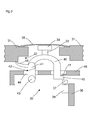
- FIG. 2 shows the embodiment FIG. 1 before performing the length adjustment of in FIG. 1 designated by the reference numeral 13 mechanical transmission element.
- FIG. 2 thus differs from the presentation FIG. 1 only to the effect that in place of the mechanical transmission element 13 a not yet matched in length mechanical transmission element 13 'occurs, the one in the FIG. 2 with x marked length over its nominal length survives.
- the desired length is in this case a length which leads to a protrusion of the mechanical transmission element 13, 13 'relative to the surface of the housing 11 attributable to an outer side of the optoelectronic sensor 10 around the in FIG FIG. 1 shown distance h leads.
- This means that the surface of the mechanical transmission element 13 'facing away from the switching element 17 is removed in its direction of movement by the distance x + h from a surface of the housing 11 attributable to an outside of the optoelectronic sensor 10.
- Fig. 3 shows a cross-sectional view of a section of another embodiment of the invention with a lever 40 as a mechanical transmission element. Shown is a section of an optoelectronic sensor 30 with an operating element, which represents the environment of the operating element.
- the operating element has a control surface 35, here shown as a teach membrane, which is arranged on a portion of a housing 31 of the optoelectronic sensor 30 on.
- the housing 31 has an in FIG. 3 not shown reference surface, which can be used for referencing the distance when adjusting the mechanical transmission element, that is, in this embodiment of the lever 40.
- the portion of the housing 31 is penetrated by a recess 32. At least in sections within the recess 32, the lever 40 is arranged so that it is movable upon actuation of the operating surface 35.
- an electronic card 36 is arranged, which is fixed in a holder, not shown.
- an electrical sensing element 38 is arranged with a switching element 37 so that upon actuation of the control surface 35, the lever 40 exerts a force on the switching element 37, which leads to a switching of the electrical sensing element 38.
- the lever 40 is mounted on one side slidably resting with a step 41 at a support point 42 and on the side at which the support point of the lever 40, in addition to a clamping body 43 in an undercut of a shaft 44 of a housing 31 of the optoelectronic sensor 30th arranged carrier 46 clipped.
- the other side of the lever 40 which triggers the switching of the electrical sensing element 38, has a nose 45 which engages behind an undercut 47 on the carrier 46, so that a captive against shaking out is given.
- a flexible spring element 48 is arranged, which, in particular in widest tolerance case, under bias on the housing 31 is supported.
- a pin 33 is arranged in this embodiment on the lever 40, via which a force exerted on the operating surface 35 on actuation of pressure in the lever 40, so that there is a one-sided tilting of the Lever 40 comes, which in turn triggers the actuation of the electrical sensing element 38 via the switching element 37.
- the adaptation preferably takes place on the pin 33. If it takes place by melting the material, the implementation of the adaptation is based on a side of the pin 33 facing the operating surface 35 arranged bead 34 made of molten material recognizable, so as to ensure that by means of the available, in FIG. 3 not shown working the switching of the electric probe element 38 can be triggered. Of course, all other procedures described above for length adjustment of the pin 33 are possible.
- the transmission element or the lever can be used in device housings of a wide variety of devices, such as measuring or control devices, in particular electronic or optoelectronic sensors, such as light barriers or light grids.
- the device housings are used in industries in which high demands are made on impermeability, temperature resistance, thermal shock resistance, mechanical abrasion resistance, resistance to external mechanical impacts, vapor and gas permeability, low moisture absorption and / or hygiene requirements, in particular in the food industry, the food industry. , Semi-luxury and / or beverage industry, the solar energy industry or the pharmaceutical industry, in which in particular the equipment used to be cleaned with chemicals, especially aggressive chemicals.
- the device housings meet the requirements up to IP69k.
Landscapes
- Switches Operated By Changes In Physical Conditions (AREA)
- Geophysics And Detection Of Objects (AREA)
Abstract
Description
Die Erfindung betrifft ein Verfahren zur Herstellung eines optoelektronischen Sensors mit einem Bedienelement und einen optoelektronischer Sensor mit einem Bedienelement.The invention relates to a method for producing an optoelectronic sensor having a control element and to an optoelectronic sensor having a control element.
In Geräten und Baugruppen kann es durch einzelne Unterbaugruppen und Einzelteile durch Toleranzverkettungen der Einzelkomponenten zu starken Gesamttoleranzschwankungen an funktionsbedingten Schnittstellen kommen. Bei einem typischen Bedienelement mit einem elektrischen Tastelement, das in der Regel auf einer Elektronik-Karte angeordnet ist, wirken Toleranzen des Schaltmechanismus des elektrischen Tastelements, also der Lage des Schaltpunktes, der angibt, wie weit das elektrische Tastelement gedrückt werden muss, ehe das Umschalten erfolgt, eine Bestücktoleranz des Schalters auf der Elektronik-Karte, eine Toleranz der Aufnahme der Elektronikkarte in das Gehäuse und eine Toleranz des Gehäuses zu einer außenliegenden Bedienfläche zusammen. Ist ein mechanisches Übertragungselement vorgesehen, wie es insbesondere im Fall von als Metallmembranen auf einem Gehäuse eines optoelektronischen Sensors ausgeführten Bedienelementen oft verwendet wird, um das Gehäuse zu durchsetzen und so die Betätigung eines im Gehäuseinneren liegenden elektrischen Tastelements zu ermöglichen, kommen auch dessen Toleranzen noch hinzu.Due to individual subassemblies and individual parts, tolerance devices of the individual components can lead to strong overall tolerance fluctuations at function-related interfaces in devices and assemblies. In a typical control element with an electrical probe element, which is usually arranged on an electronic card, tolerances of the switching mechanism of the electrical probe element, so the position of the switching point, which indicates how far the electrical probe element must be pressed before the switching takes place, a loading tolerance of the switch on the electronics card, a tolerance of the inclusion of the electronic card in the housing and a tolerance of the housing to an external control surface together. If a mechanical transmission element is provided, as is often used, in particular in the case of controls designed as metal diaphragms on a housing of an optoelectronic sensor, in order to penetrate the housing and thus enable actuation of an electrical probe element located inside the housing, its tolerances are also added ,
Um einen Schaltvorgang auszulösen, muss das elektrische Tastelement um einen Mindesthub betätigt werden, während zugleich für die Bedienfläche nur ein begrenzter Hub verfügbar ist. Durch Kombination der Einzeltoleranzen zu einer Gesamttoleranz kann es dabei zu drei unterschiedlichen Problemen kommen:
- 1) Wenn die Toleranzen so zusammenwirken, dass ein maximaler Abstand zwischen der Bedienfläche und dem Schaltpunkt des elektrischen Tastelements vorliegt, kann es vorkommen, dass der maximal verfügbare Hub nicht ausreicht, um zu einem Schalten des elektrischen Tastelements zu führen. Die Betätigung der Bedienfläche bleibt folgenlos, das Bedienelement versagt.
- 2) Wenn die Toleranzen so zusammenwirken, dass ein minimaler Abstand zwischen der Bedienfläche und dem Schaltpunkt des elektrischen Tastelements vorliegt, kann beim Fügen der Baugruppe durch Vorspannung zwischen Bedienfläche und elektrischem Tastelement eine Dauerbetätigung ausgelöst werden.
- 3) Wenn die Toleranzen so zusammenwirken, dass ein Abstand zwischen minimalem Abstand und Sollabstand zwischen Bedienfläche und dem Schaltpunkt des elektrischen Tastelements vorliegt, ist der verfügbare Hub zu groß. Dann kann es vorkommen, dass der Benutzer mit hohem Krafteinsatz das Bedienelement betätigt und dadurch nicht nur das Schalten des elektrischen Tastelements bewirkt, sondern dieses durch ungedämpftes Einleiten der aufgewendeten Bedienkraft beschädigt. Lagerungen und Lötverbindungen eines elektrischen Tastelements sind üblicherweise für deutlich geringere Kräfte ausgelegt, als maximal über Bedienfläche und ein mechanisches Übertragungselement übertragbar sind.
- 1) If the tolerances cooperate so that there is a maximum distance between the operating surface and the switching point of the electrical sensing element, it may happen that the maximum available stroke is not sufficient to lead to a switching of the electrical sensing element. The operation of the control surface remains without consequences, the operating element fails.
- 2) If the tolerances cooperate so that there is a minimum distance between the operating surface and the switching point of the electrical sensing element, a permanent actuation can be triggered when joining the assembly by bias between the control surface and the electrical probe element.
- 3) If the tolerances interact so that there is a distance between minimum distance and nominal distance between the operating surface and the switching point of the electrical probe element, the available stroke is too large. Then it can happen that the user operates with high force input the control element and thereby not only causes the switching of the electrical probe element, but this damaged by undamped initiation of the applied operating force. Bearings and solder joints of an electrical probe element are usually designed for significantly lower forces, as a maximum on control surface and a mechanical transmission element are transferable.
Aufgabe der Erfindung ist die Bereitstellung eines Verfahrens zur Herstellung eines optoelektronischen Sensors mit einem Bedienelement und einem optoelektronischer Sensor mit einem Bedienelement, die diese Nachteile nicht mehr aufweisen.The object of the invention is to provide a method for producing an optoelectronic sensor with a control element and an optoelectronic sensor with a control element, which no longer have these disadvantages.
Die Aufgabe wird erfindungsgemäß gelöst durch ein Verfahren mit den Merkmalen des Patentanspruchs 1 und ein Bedienelement mit den Merkmalen des Patentanspruchs 9. Vorteilhafte Ausgestaltungen und Weiterbildungen der Erfindung sind in den Unteransprüchen angegeben.The object is achieved by a method with the features of claim 1 and an operating element with the features of the claim 9. Advantageous embodiments and further developments of the invention are specified in the subclaims.
Das erfindungsgemäße Verfahren zur Herstellung eines optoelektronischen Sensors mit einem Bedienelement, das eine Bedienfläche, ein elektrisches Tastelement und ein mechanisches, als Folge einer Betätigung der Bedienfläche bewegliches Übertragungselement zur Betätigung des elektrischen Tastelements aufweist, weist zumindest die folgenden Schritte auf: Anordnen des elektrischen Tastelements in oder an dem optoelektronischen Sensor, Einlegen des mechanischen Übertragungselements in den optoelektronischen Sensor, so dass durch Bewegung des mechanischen Übertragungselements ein Schalten des elektrischen Tastelements auslösbar ist, Überführen des mechanischen Übertragungselements in eine Position, in der es ein Schalten des elektrischen Tastelements auslöst und Festhalten des mechanischen Übertragungselements in dieser Position, und Anpassen der Länge des mechanischen Übertragungselements in Arbeitsrichtung zur Toleranzeliminierung. Unter der Arbeitsrichtung wird dabei die Richtung verstanden, in die in das mechanische Übertragungselement bei Betätigung der Bedienfläche des Bedienelements Kraft eingeleitet wird. Insbesondere können die Schritte in dieser Abfolge durchgeführt werden. Die Längenanpassung sollte vorteilhafterweise vor dem endgültigen Anordnen der Bedienfläche an dem optoelektronischen Sensor erfolgen.The inventive method for producing an optoelectronic sensor having a control element, which has a control surface, an electrical sensing element and a mechanical, as a result of actuation of the control surface movable transmission element for actuating the electrical sensing element comprises at least the following steps: arranging the electrical sensing element in or on the optoelectronic sensor, inserting the mechanical transmission element into the optoelectronic sensor, so that switching of the electrical sensing element can be triggered by movement of the mechanical transmission element, transferring the mechanical transmission element into a position in which it triggers switching of the electrical sensing element and holding the mechanical transmission element in this position, and adjusting the length of the mechanical transmission element in the working direction for tolerance elimination. The working direction is understood to be the direction in which force is introduced into the mechanical transmission element when the operating surface of the operating element is actuated. In particular, the steps in this sequence can be performed. The length adjustment should advantageously take place before the final positioning of the operating surface on the optoelectronic sensor.
Dadurch, dass das mechanische Übertragungselement erfindungsgemäß in eine Position überführt wird, in der es ein Schalten des elektrischen Tastelementes auslöst und dann die Länge des mechanischen Übertragungselements individuell angepasst wird, werden Bauteiltoleranzen ausgeglichen, so dass bei den auf diese Weise hergestellten optoelektronischen Sensoren mit Bedienelement die oben genannten Probleme nicht mehr auftreten können. Der Ausschuss an Geräten bei der Herstellung und das Risiko einer Beschädigung des Bedienelements bei seiner Betätigung wird sicher eliminiert, was zu spürbarer Kostenreduktion führt.Due to the fact that the mechanical transmission element according to the invention is transferred to a position in which it triggers switching of the electrical probe element and then the length of the mechanical transmission element is adjusted individually, component tolerances are compensated, so that in the optoelectronic sensors with control element produced in this way above problems can no longer occur. The waste of equipment during manufacturing and the risk of damaging the operating element when it is actuated are reliably eliminated, which leads to noticeable cost reductions.
Das Einlegen des mechanischen Übertragungselements umfasst vorteilhafterweise das Anschlagen in eine Aufnahme referenzierend zu einer beispielsweise im oder am Gehäuse des optoelektronischen Sensors vorgesehenen Referenzfläche.The insertion of the mechanical transmission element advantageously comprises striking into a receptacle referencing a reference surface provided, for example, in or on the housing of the optoelectronic sensor.
Das Überführen des mechanischen Übertragungselements in eine Position, in der es ein Schalten des elektrischen Tastelementes auslöst, kann beispielsweise mittels eines gefederten Elementes geschehen, das auf einen Vorsprung oder Abschnitt des mechanischen Übertragungselements einwirkt, der nicht von der nachfolgenden Anpassung der Länge in Arbeitsrichtung betroffen wird.The transfer of the mechanical transmission element into a position in which it triggers switching of the electrical sensing element, for example, by means of a sprung element which acts on a projection or portion of the mechanical transmission element, which is not affected by the subsequent adjustment of the length in the working direction ,
In einer ersten bevorzugten Ausführungsform erfolgt das Anpassen der Länge des mechanischen Übertragungselements durch Abschmelzen. Dazu kann beispielsweise ein heißer Stempel auf das mechanische Übertragungselement, der so zu einer Gehäusekante referenziert ist, dass auch bei dem kleinsten innerhalb der Toleranzen für die Bedienfläche auftretenden Hub der Schaltprozess ausgelöst wird, gefahren werden. Das abgeschmolzene Material setzt sich als umlaufender Wulst am mechanischen Übertragungselement ab.In a first preferred embodiment, the adaptation of the length of the mechanical transmission element takes place by melting. For this purpose, for example, a hot stamp on the mechanical transmission element, which is referenced to a housing edge, that even with the smallest occurring within the tolerances for the control surface stroke of the switching process is triggered, are driven. The molten material settles as a circumferential bead on the mechanical transmission element.
Zweckmäßigerweise wird als Material für das mechanische Übertragungselement ein Material verwendet, das sich nach dem Abschmelzvorgang gut vom Heißstempel trennen lässt. Bevorzugt ist die Verwendung von POM-Kunststoff wegen der guten Gleiteigenschaften, hohen Elastizität und guten Schmelzeigenschaften dieses Materials. Bei Verwendung dieses Materials kann ein auf 300° C bis 400° C, insbesondere 380° C daueraufgeheizter Stahlstempel benutzt werden, abhängig von der Geometrie und Material des Übertragungselements, wenn die beim Verbrennen des POM-Materials entstehenden kanzerogenen Dämpfe abgesaugt werden. Alternativ kann mit einem sogenannten "Heat-Staker" das Material unterhalb der Verbrennungsgrenze abgeschmolzen werden. Die Ablösung vom abgeschmolzenen mechanischen Übertragungselement erfolgt durch eine termporäre Kühlung des Heißstempels durch einen Luftstrom.Conveniently, a material is used as the material for the mechanical transmission element, which can be easily separated from the hot stamp after Abschmelzvorgang. Preference is given to the use of POM plastic because of the good sliding properties, high elasticity and good melting properties of this material. When using this material, a steel die permanently heated to 300 ° C to 400 ° C, especially 380 ° C, may be used, depending on the geometry and material of the transfer element, when the carcinogenic vapors resulting from the burning of the POM material are exhausted. Alternatively, the material below the combustion limit can be melted off with a so-called "heat staker". The detachment from the molten mechanical transmission element takes place by a termporäre cooling of the hot stamp by an air flow.
In einer zweiten bevorzugten Ausführungsform erfolgt das Anpassen der Länge des mechanischen Übertragungselements durch Abfräsen. Die Vorteile beim Abfräsen liegen darin, dass eine sehr gute Maßhaltigkeit und ein sehr hohes Toleranzausgleichsvermögen gegeben sind, allerdings kann ein gewisses Risiko, dass es zum Eindringen von Stäuben oder Spänen in den optoelektronischen Sensor kommt, bestehen. Die zu erreichende Frästiefe kann fest auf einen Bezugsanschlag, z. B. eine Bezugskante, am oder im Gehäuse des optoelektronischen Sensors referenziert werden.In a second preferred embodiment, adjusting the length of the mechanical transmission element by milling. The advantages of milling This is because there is a very good dimensional stability and a very high tolerance compensation capacity, but there may be some risk of dust or chips entering the optoelectronic sensor. The milling depth to be achieved can be fixed to a reference stop, z. As a reference edge, be referenced on or in the housing of the optoelectronic sensor.
In einer dritten bevorzugten Ausführungsform erfolgt das Anpassen der Länge des mechanischen Übertragungselements durch Abkneifen. Auch hier kann die zu erreichende Tiefe über einen Bezugsanschlag, z. B. eine Bezugskante, am oder im Gehäuse des optoelektronischen Sensors referenziert werden. Diese Vorgehensweise zeichnet sich durch einen besonders einfachen Aufbau und ein hohes Toleranzausgleichsvermögen aus, allerdings ist die Prozesssicherheit weniger gut als bei alternativen Vorgehensweisen und die Form der Fläche des mechanischen Übertragungselements, die mit der Bedienfläche wechselwirkt, ist nicht optimal.In a third preferred embodiment, the adaptation of the length of the mechanical transmission element by means of a snap-on takes place. Again, the depth to be reached via a reference stop, z. As a reference edge, be referenced on or in the housing of the optoelectronic sensor. This approach is characterized by a particularly simple structure and a high tolerance compensation capability, however, the process reliability is less good than in alternative approaches and the shape of the surface of the mechanical transmission element that interacts with the control surface is not optimal.
In einer vierten bevorzugten Ausführungsform erfolgt das Anpassen der Länge des mechanischen Übertragungselements durch Auftrag eines Klebstoffs. Im Gegensatz zu den vorstehenden Ausgestaltungen wird dabei ein mechanisches Übertragungselement verwendet, das verlängert werden muss, um die Solllänge zu erreichen. Zur Verlängerung des mechanischen Übertragungselements wird auf die der Bedienfläche zugewandte Oberfläche des mechanischen Übertragungselements ein zäher Klebstoff aufgetragen, so dass sich ein Klebstofftropfen bildet, der über die Sollhöhe hinausragt. Anschließend wird die Höhe des Klebstofftropfens dadurch angepasst, dass ein am Klebstoff nicht haftendes Distanzstück, z. B. aus Teflon, mit einem Bezugsanschlag am oder im Gehäuse in Anschlag gebracht wird. Diese Lösung erreicht gute Maßhaltigkeit, das Toleranzausgleichsvermögen ist aber gering. Die Geschwindigkeit bei dieser Vorgehensweise ist wegen der Aushärtezeit des Klebstoffs tendenziell langsam, sie kann aber beschleunigt werden, wenn ein Klebstoff verwendet wird, der durch Bestrahlen mit UV-Licht ausgehärtet wird. Als Distanzstück verwendet man dann ein lichtundurchlässiges, nicht materialanhaftendes Plättchen, beispielsweise ein Plättchen aus Teflon, dass Licht eines UV-Strahlers, der bezogen auf den Bezugsanschlag mit dem Distanzstück auf den Klebstoff aufgefahren und für die benötigte Aushärtezeit eingeschaltet wird, nur wenig geschwächt wird.In a fourth preferred embodiment, adjusting the length of the mechanical transmission element by applying an adhesive takes place. In contrast to the above embodiments, while a mechanical transmission element is used, which must be extended in order to achieve the desired length. To extend the mechanical transmission element, a tough adhesive is applied to the surface of the mechanical transmission element facing the operating surface, so that an adhesive drop is formed which projects beyond the desired height. Subsequently, the height of the adhesive drop is adjusted by a non-adhesive adhesive on the spacer, for. B. Teflon, with a reference stop on or in the housing is brought into abutment. This solution achieves good dimensional stability, but the tolerance compensation capability is low. The speed of this approach tends to be slow because of the curing time of the adhesive, but it can be accelerated if an adhesive that is cured by exposure to UV light is used. As a spacer, it is then used an opaque, not material adhering platelets, such as a Teflon plate that light of a UV lamp, based on the reference stop with the spacer on the Adhesive raised and turned on for the required curing time, only slightly weakened.
Ein zusätzlicher, separater zentraler Aspekt der Erfindung ist der Gedanke, das mechanische Übertragungselement eines optoelektronischen Sensors mit einem Bedienelement als ein Hebel auszulegen. Der Hebel ist beispielsweise an einem Ende gelagert und die Betätigung des Schaltelements erfolgt am gegenüberliegenden Ende des Hebels. Dazwischen wirkt das Tastelement auf den Hebel. Dadurch kann eine Vergrößerung des Hubes, bezogen vom Bedienhub zum Ausgangshub am Schaltelement des elektrischen Tastelement, erreicht werden.An additional, separate central aspect of the invention is the idea of designing the mechanical transmission element of an optoelectronic sensor with a control element as a lever. The lever is for example mounted at one end and the actuation of the switching element takes place at the opposite end of the lever. In between, the feeler element acts on the lever. As a result, an increase in the stroke, based on the operating stroke for the output stroke on the switching element of the electrical probe element, can be achieved.
In Weiterbildung der Erfindung ist es auch vorgesehen, eine Verkleinerung des Hubes vorzusehen. Dazu ist ein Hebel an einem Ende gelagert und die Betätigung des Tastelementes erfolgt am gegenüberliegenden Ende des Hebels. Dazwischen erfolgt die Betätigung des Schaltelements. Dadurch ist zum einen ein vergrößerter Hub des Tastelementes möglich und auch eine Vergrößerung der Kraft auf das Betätigungselement.In a further development of the invention, it is also provided to provide a reduction of the stroke. For this purpose, a lever is mounted at one end and the actuation of the probe element takes place at the opposite end of the lever. In between, the actuation of the switching element takes place. As a result, on the one hand, an enlarged stroke of the probe element is possible and also an increase in the force on the actuating element.
Besonders bevorzugt ist ein elastisch verformbarer Hebel, da dadurch eine zu hohe Kraftübertragung ausgeschlossen wird. Bei zu großem Bedienhub biegt sich der Hebel durch und unterbindet so eine Kraftübertragung zum elektrischen Tastelement und auf dessen Lagerung. Die Elastizität kann durch Materialwahl, geometrische Anordnung oder Beeinflussung des Flächenträgheitsmomentes durch Querschittsverjüngungen eingestellt werden, wobei sichergestellt sein muss, dass die minimal erforderliche Betätigungskraft und der minimal erforderliche Hub für das Schaltelement des elektrischen Tastelements erreicht werden. All diese Vorteile werden auch unabhängig von der Toleranzeliminierung durch Anpassung des mechanischen Übertragungselements erreicht.Particularly preferred is an elastically deformable lever, as a result of excessive power transmission is excluded. If the operating stroke is too great, the lever bends and prevents a transmission of force to the electrical probe element and its storage. The elasticity can be adjusted by material selection, geometric arrangement or influencing the area moment of inertia by Querschittsverjüngungen, which must be ensured that the minimum required actuation force and the minimum required stroke for the switching element of the electrical probe element can be achieved. All these advantages are achieved independently of the elimination of tolerance by adaptation of the mechanical transmission element.
In einer besonders bevorzugten Ausgestaltung des Verfahrens verwendet man nicht nur einen Hebel, sondern einen Hebel, der besonders gut geeignet für die erfindungsgemäße Anpassung der Länge in Arbeitsrichtung ist. Dies ist ein Hebel, bei der ein an den Hebel angeordneter Zapfen die bei Betätigung der Bedienfläche ausgeübte Kraft in den Hebel einleitet, da dann die Längenanpassung auf diesen Zapfen beschränkt bleiben kann.In a particularly preferred embodiment of the method is used not only a lever, but a lever which is particularly well suited for the inventive adjustment of the length in the working direction. This is a lever, in which a pin arranged on the lever when pressing the operating surface exerted applied force in the lever, since then the length adjustment can remain limited to this pin.
Besonders vorteilhaft ist es bei dieser Ausgestaltung, wenn der Hebel nach dem Einlegen verliersicher an dem optoelektronischen Sensor fixiert wird. Dies kann z. B. mit Rast- und Klemmverbindungen realisiert werden. Insbesondere kann z. B. der Hebel auf der Seite, mit der das elektrische Tastelement bedient wird, einen Vorsprung aufweisen, der schräg von oben an einem im Gehäuse des optoelektronischen Sensors angeordneten Hinterschnitt vorbeigeführt wird. Anschließend wird der gegenüberliegende Bereich des Hebels in einen Schacht, der im Gehäuse oder in einer im Gehäuse angeordneten Halterung vorgesehen ist, eingeclipst.It is particularly advantageous in this embodiment, when the lever is fixed captive after insertion on the optoelectronic sensor. This can be z. B. be realized with locking and clamping connections. In particular, z. B. the lever on the side with which the electrical probe element is operated, having a projection which is guided obliquely from above on a arranged in the housing of the optoelectronic sensor undercut. Subsequently, the opposite region of the lever is clipped into a shaft which is provided in the housing or in a holder arranged in the housing.
Der erfindungsgemäße optoelektronische Sensor weist mindestens ein Bedienelement auf, das seinerseits eine Bedienfläche, ein elektrisches Tastelement und ein mechanisches, als Folge einer Betätigung der Bedienfläche bewegliches Übertragungselement zur Betätigung des elektrischen Tastelements aufweist. Erfindungswesentlich ist, dass das mechanische Übertragungselement, insbesondere seine Länge in Arbeitsrichtung, zur Toleranzeliminierung angepasst ist. Dadurch werden Bauteiltoleranzen ausgeglichen, so dass bei den auf diese Weise hergestellten optoelektronischen Sensoren mit Bedienelement die oben genannten Probleme nicht mehr auftreten können. Der Ausschuss an Geräten bei der Herstellung und das Risiko einer Beschädigung des Bedienelements bei seiner Betätigung werden sicher eliminiert, was zu spürbarer Kostenreduktion führt.The optoelectronic sensor according to the invention has at least one operating element, which in turn has a control surface, an electrical sensing element and a mechanical, as a result of actuation of the control surface movable transmission element for actuating the electrical sensing element. It is essential to the invention that the mechanical transmission element, in particular its length in the working direction, is adapted to eliminate tolerance. As a result, component tolerances are compensated so that the above-mentioned problems can no longer occur in the optoelectronic sensors with control element produced in this way. The waste of equipment during manufacturing and the risk of damaging the operating element when it is actuated are reliably eliminated, which leads to noticeable cost reductions.
Besonders bevorzugt ist ein elastisch verformbarer Hebel, da dadurch eine zu hohe Kraftübertragung ausgeschlossen wird. Bei zu großem Bedienhub biegt sich der Hebel durch und unterbindet so eine Kraftübertragung zum elektrischen Tastelement und auf dessen Lagerung. Die Elastizität kann durch Materialwahl, geometrische Anordnung oder Beeinflussung des Flächenträgheitsmomentes durch Querschittsverjüngungen eingestellt werden. Besonders gut geeignet für die erfindungsgemäße Anpassung der Länge in Arbeitsrichtung ist ein Hebel, bei dem ein an dem Hebel angeordneter Zapfen die bei Betätigung der Bedienfläche ausgeübte Kraft in den Hebel einleitet, da dann die Längenanpassung auf diesen Zapfen beschränkt bleiben kann.Particularly preferred is an elastically deformable lever, as a result of excessive power transmission is excluded. If the operating stroke is too great, the lever bends and prevents a transmission of force to the electrical probe element and its storage. The elasticity can be adjusted by material selection, geometric arrangement or influencing the area moment of inertia by Querschittsverjüngungen. Particularly suitable for the inventive adjustment of the length in the working direction is a lever in which a pin arranged on the lever exerted the force on actuation of the operating surface Force in the lever introduces, since then the length adjustment can remain limited to this pin.
Eine verliersichere Variante des optoelektronischen Sensors hat die weiteren Merkmale, dass ein erstes Ende des Hebels an einem Hinterschnitt vorbeigeführt ist und dass ein zweites Ende des Hebels in einen Schacht eingeclipst ist.A captive variant of the optoelectronic sensor has the further features that a first end of the lever is guided past an undercut and that a second end of the lever is clipped into a shaft.
Wenn an der Seite des Hebels, an der der Hebel aufliegend gelagert ist, ein flexibles Federelement angebracht ist, welches sich unter Vorspannung am Außengehäuse abstützt, erhält man einen optoelektronischen Sensor, bei dem Rasselgeräusche vermieden werden. Im engsten Toleranzfall wird dieses Federelement bei Betätigung des Hebels maximal durchgebogen. Die erforderliche Durchbiegekraft addiert sich zur eigentlichen Betätigungskraft des Hebels (ohne Federelement) hinzu.If a flexible spring element is mounted on the side of the lever on which the lever is mounted, which is supported under pretension on the outer housing, one obtains an optoelectronic sensor in which rattling noises are avoided. In the narrowest tolerance case of this spring element is bent maximum when operating the lever. The required bending force is added to the actual operating force of the lever (without spring element).
Ein Ausführungsbeispiel der Erfindung wird anhand der folgenden Figuren ausführlich erläutert.An embodiment of the invention will be explained in detail with reference to the following figures.
Es zeigt:
- Fig. 1
- eine Querschnittsdarstellung eines Ausschnitts eines ersten Ausführungsbeispiels der Erfindung,
- Fig. 2
- das Ausführungsbeispiel aus
Figur 1 vor der Durchführung der Längenanpassung des mechanischen Übertragungselements und - Fig. 3
- eine Querschnittsdarstellung eines Ausschnitts eines weiteren Ausführungsbeispiels der Erfindung mit einem Hebel als mechanischem Übertragungselement.
- Fig. 1
- a cross-sectional view of a section of a first embodiment of the invention,
- Fig. 2
- the embodiment
FIG. 1 before performing the length adjustment of the mechanical transmission element and - Fig. 3
- a cross-sectional view of a section of another embodiment of the invention with a lever as a mechanical transmission element.
Für gleiche Bauteile gleicher Ausführungsbeispiele werden dieselben Bezugszeichen verwendet.The same reference numerals are used for the same components of the same exemplary embodiments.
Der Abschnitt des Gehäuses 11 wird von einer Ausnehmung 12 durchsetzt. Zumindest abschnittsweise innerhalb der Ausnehmung 12 ist ein mechanisches Übertragungselement 13 so angeordnet, dass es bei Betätigung der Bedienfläche 15 beweglich ist. Im Inneren des Gehäuses 11 ist eine Elektronikkarte 16 angeordnet. Auf der Elektronikkarte 16 ist ein elektrisches Tastelement 18 mit einem Schaltelement 17 so angeordnet, dass bei Betätigung der Bedienfläche 14 das mechanische Übertragungselement 13 eine Kraft auf das Schaltelement 17 ausübt, die zu einem Schalten des elektrischen Tastelements 18 führt.The portion of the
Die Länge des mechanischen Übertragungselements 13 ist in Arbeitsrichtung zur Toleranzeliminierung angepasst, wie anhand eines an der Bedienfläche 15 zugewandten Seite des mechanischen Übertragungselements 13 angeordneten Wulstes 14 aus geschmolzenem Material erkennbar ist, so dass sichergestellt ist, dass mittels des Arbeitshubes h das Schalten des elektrischen Tastelements 18 ausgelöst werden kann. Das mechanische Übertragungselement 13 weist weiter an einer Seite einen Vorsprung 21 oder eine Stufe auf, die in die Ausnehmung 12 hineinragt. An dieser Stufe kann bei der Herstellung des optoelektronischen Sensors ein nicht dargestellter Niederhalter eingreifen, der das mechanische Übertragungselement 13 in eine Position überführt, in der es ein Schalten des elektrischen Tastelements 18 auslöst und das mechanische Übertragungselement 13 in dieser Position festhält, während die Anpassung des mechanischen Übertragungselements 13 erfolgt.The length of the
Je nachdem wie die Anpassung des mechanischen Übertragungselements erfolgt ist, kann ihre Durchführung auch statt aus dem Vorhandensein des Wulstes 14 aus dem Vorhandensein einer Fräsfläche, einer Oberfläche mit Kneifspuren oder eines Klebstofftropfens jeweils auf der der Bedienfläche 14 zugewandten Seite gefolgert werden.Depending on how the adaptation of the mechanical transmission element has taken place, its implementation can also be inferred instead of from the presence of the
Der Abschnitt des Gehäuses 31 wird von einer Ausnehmung 32 durchsetzt. Zumindest abschnittsweise innerhalb der Ausnehmung 32 ist der Hebel 40 so angeordnet, dass er bei Betätigung der Bedienfläche 35 beweglich ist.The portion of the
Im Inneren des Gehäuses 31 ist eine Elektronikkarte 36 angeordnet, die in einer nicht dargestellten Halterung fixiert ist. Auf der Elektronikkarte 36 ist ein elektrisches Tastelement 38 mit einem Schaltelement 37 so angeordnet, dass bei Betätigung der Bedienfläche 35 der Hebel 40 eine Kraft auf das Schaltelement 37 ausübt, die zu einem Schalten des elektrischen Tastelements 38 führt.Inside the
Der Hebel 40 ist einseitig verschiebbar aufliegend mit einer Stufe 41 an einem Auflagepunkt 42 gelagert und an der Seite, an der sich der Auflagepunkt des Hebels 40 befindet, zusätzlich mit einem Klemmkörper 43 in einen Hinterschnitt eines Schachts 44 eines im Gehäuse 31 des optoelektronischen Sensors 30 angeordneten Trägers 46 eingeclipst. Die andere Seite des Hebels 40, die das Schalten des elektrischen Tastelements 38 auslöst, weist eine Nase 45 auf, die einen Hinterschnitt 47 am Träger 46 hintergreift, so dass eine Verliersicherung gegen Herausschütteln gegeben ist.The
Eine weitere Zusatzfunktion des Hebels 40, nämlich eine ein Rasseln vermeidende Fixierung des Hebels 40 in dem optoelektronischen Sensor 30 wird dadurch erzielt, dass an der Seite des Hebels, an der sie gelagert ist, ein flexibles Federelement 48 angeordnet ist, das sich, insbesondere im weitesten Toleranzfall, unter Vorspannung am Gehäuse 31 abstützt.Another additional function of the
Zur Anpassung der Länge des Hebels 40 in Arbeitsrichtung zur Toleranzeliminierung ist in dieser Ausführungsform an dem Hebel 40 ein Zapfen 33 angeordnet, über den ein bei Betätigung auf die Bedienfläche 35 ausgeübter Druck in den Hebel 40 eingeleitet wird, so dass es zu einem einseitigen Kippen des Hebels 40 kommt, was wiederum die Betätigung des elektrischen Tastelements 38 über das Schaltelement 37 auslöst. Die Anpassung erfolgt vorzugsweise am Zapfen 33. Wenn sie durch Schmelzen des Materials erfolgt, ist die Durchführung der Anpassung anhand eines an der Bedienfläche 35 zugewandten Seite des Zapfens 33 angeordneten Wulstes 34 aus geschmolzenem Material erkennbar, so dass sichergestellt ist, dass mittels des verfügbaren, in
In der Ausführungsform nach
Das Übertragungselement oder der Hebel kann in Gerätegehäusen der unterschiedlichsten Geräte, beispielsweise von Mess- oder Regelgeräten, insbesondere von elektronischen oder optoelektronischen Sensoren, wie beispielsweise Lichtschranken oder Lichtgittern, verwendet werden. Die Gerätegehäuse finden Verwendung in Industriezweigen, in welchen hohe Anforderungen an Dichtigkeit, Temperaturbeständigkeit, Temperaturwechselbeständigkeit, mechanische Abriebfestigkeit, Durchdruckbeständigkeit gegen äußere mechanische Einwirkungen, Dampf- und Gasdurchlässigkeit, geringe Feuchtigkeitsaufnahme und/oder Hygieneanforderungen vorhanden sind, insbesondere im Bereich der Lebensmittelindustrie, der Nahrungs-, Genussmittel- und/oder Getränkeindustrie, der Solarenergieindustrie oder der Pharmaindustrie, in welchen insbesondere die verwendeten Geräte mit Chemikalien, insbesondere aggressiven Chemikalien gereinigt werden. Die Gerätegehäuse erfüllen die Anforderungen bis zu der Dichtigkeitsklasse IP69k.The transmission element or the lever can be used in device housings of a wide variety of devices, such as measuring or control devices, in particular electronic or optoelectronic sensors, such as light barriers or light grids. The device housings are used in industries in which high demands are made on impermeability, temperature resistance, thermal shock resistance, mechanical abrasion resistance, resistance to external mechanical impacts, vapor and gas permeability, low moisture absorption and / or hygiene requirements, in particular in the food industry, the food industry. , Semi-luxury and / or beverage industry, the solar energy industry or the pharmaceutical industry, in which in particular the equipment used to be cleaned with chemicals, especially aggressive chemicals. The device housings meet the requirements up to IP69k.
- 10,3010.30
- Optoelektronischer Sensor mit BedienelementOpto-electronic sensor with control element
- 11,3111.31
- Gehäusecasing
- 12,3212.32
- Ausnehmungrecess
- 1313
- mechanisches Übertragungselementmechanical transmission element
- 14,3414.34
- Wulstbead
- 15,3515.35
- Bedienflächeoperating surface
- 16,3616.36
- Elektronikkarteelectronic card
- 17,3717,37
- Schaltelementswitching element
- 18,3818.38
- elektrisches Tastelementelectrical probe element
- 2121
- Vorsprunghead Start
- 3333
- Zapfenspigot
- 4141
- Stufestep
- 4242
- Auflagepunktsupport point
- 4343
- Klemmkörperclamping bodies
- 4444
- Schachtshaft
- 4545
- Nasenose
- 4646
- Trägercarrier
- 4747
- Hinterschnittundercut
- 4848
- flexibles Federelementflexible spring element
- 4949
- Hebellever
Claims (11)
aufweist.
having.
dadurch gekennzeichnet, dass das Anpassen der Länge des mechanischen Übertragungselements (13,40) durch Abschmelzen erfolgt.Method according to claim 1,
characterized in that the adjustment of the length of the mechanical transmission element (13,40) is carried out by melting.
dadurch gekennzeichnet, dass das Anpassen der Länge des mechanischen Übertragungselements (13,40) durch Abfräsen erfolgt.Method according to claim 1,
characterized in that the adjustment of the length of the mechanical transmission element (13,40) is carried out by milling.
dadurch gekennzeichnet, dass das Anpassen der Länge des mechanischen Übertragungselements (13,40) durch Abkneifen erfolgt.Method according to claim 1,
characterized in that the adjustment of the length of the mechanical transmission element (13,40) is carried out by means of pinching.
dadurch gekennzeichnet, dass das Anpassen der Länge des mechanischen Übertragungselements (13,40) durch Auftrag eines Klebstoffs erfolgt.Method according to claim 1,
characterized in that the adjustment of the length of the mechanical transmission element (13,40) is carried out by applying an adhesive.
dadurch gekennzeichnet, dass der Klebstoff durch Bestrahlen mit UV-Licht ausgehärtet wird.Method according to claim 5,
characterized in that the adhesive is cured by irradiation with UV light.
dadurch gekennzeichnet, dass das mechanische Übertragungselement (13,40) ein Hebel (40) ist.Method according to a preceding claim,
characterized in that the mechanical transmission element (13, 40) is a lever (40).
dadurch gekennzeichnet, dass der Hebel (40) nach dem Einlegen verliersicher an oder in dem optoelektronischen Sensor (10,30) fixiert wird.Method according to claim 7,
characterized in that the lever (40) after insertion captive on or in the optoelectronic sensor (10,30) is fixed.
dadurch gekennzeichnet, dass das mechanische Übertragungselement (13,40) in Arbeitsrichtung zur Toleranzeliminierung angepasst ist und/oder ein Hebel ist.Optoelectronic sensor (10, 30) with an operating element that has a control surface (15, 35), an electrical sensing element (18, 38) and a mechanical transmission element (13, 40) that can be moved as a result of an actuation of the control surface (15, 35) for actuating the electrical probe element,
characterized in that the mechanical transmission element (13,40) is adapted in the working direction for tolerance elimination and / or is a lever.
dadurch gekennzeichnet, dass ein erstes Ende des Hebels (40) an einem Hinterschnitt (47) vorbeigeführt ist und dass ein zweites Ende des Hebels (40) in einen Schacht (44) eingeclipst ist.Optoelectronic sensor (10,30) according to claim 9,
characterized in that a first end of the lever (40) is guided past an undercut (47) and that a second end of the lever (40) is clipped into a slot (44).
dadurch gekennzeichnet, dass an der Seite des Hebels (40), an der der Hebel (40) aufliegend gelagert ist, ein flexibles Federelement (48) angebracht ist, welches sich unter Vorspannung am Gehäuse (11) abstützt.Optoelectronic sensor (10,30) according to claim 9 or 10,
characterized in that on the side of the lever (40) on which the lever (40) is mounted lying, a flexible spring element (48) is mounted, which is biased on the housing (11).
Applications Claiming Priority (1)
| Application Number | Priority Date | Filing Date | Title |
|---|---|---|---|
| DE201010024900 DE102010024900B3 (en) | 2010-06-24 | 2010-06-24 | Method for producing an optoelectronic sensor with a control element and optoelectronic sensor with a control element |
Publications (2)
| Publication Number | Publication Date |
|---|---|
| EP2400664A1 true EP2400664A1 (en) | 2011-12-28 |
| EP2400664B1 EP2400664B1 (en) | 2013-11-06 |
Family
ID=43902319
Family Applications (1)
| Application Number | Title | Priority Date | Filing Date |
|---|---|---|---|
| EP11162554.7A Active EP2400664B1 (en) | 2010-06-24 | 2011-04-15 | Method for producing an optoelectronic sensor with an operating element |
Country Status (2)
| Country | Link |
|---|---|
| EP (1) | EP2400664B1 (en) |
| DE (1) | DE102010024900B3 (en) |
Families Citing this family (1)
| Publication number | Priority date | Publication date | Assignee | Title |
|---|---|---|---|---|
| DE202015104820U1 (en) | 2015-09-11 | 2016-12-14 | Sick Ag | sensor |
Citations (3)
| Publication number | Priority date | Publication date | Assignee | Title |
|---|---|---|---|---|
| US4536625A (en) * | 1983-04-20 | 1985-08-20 | Bebie Alain M | Keyboard design |
| DE3214446C2 (en) * | 1982-04-20 | 1987-04-02 | Thyssen-M.A.N. Aufzuege Gmbh, 7303 Neuhausen, De | |
| EP0777327A1 (en) * | 1995-11-30 | 1997-06-04 | Haschkamp, Joachim, Dipl.-Ing. | Push button switch for household appliances |
Family Cites Families (2)
| Publication number | Priority date | Publication date | Assignee | Title |
|---|---|---|---|---|
| JP3941357B2 (en) * | 2000-08-21 | 2007-07-04 | 松下電器産業株式会社 | Pushbutton switch and composite switch using the same |
| EP2034499A4 (en) * | 2006-06-22 | 2012-01-11 | Covac Co Ltd | Switch responsive to see-saw key |
-
2010
- 2010-06-24 DE DE201010024900 patent/DE102010024900B3/en not_active Expired - Fee Related
-
2011
- 2011-04-15 EP EP11162554.7A patent/EP2400664B1/en active Active
Patent Citations (3)
| Publication number | Priority date | Publication date | Assignee | Title |
|---|---|---|---|---|
| DE3214446C2 (en) * | 1982-04-20 | 1987-04-02 | Thyssen-M.A.N. Aufzuege Gmbh, 7303 Neuhausen, De | |
| US4536625A (en) * | 1983-04-20 | 1985-08-20 | Bebie Alain M | Keyboard design |
| EP0777327A1 (en) * | 1995-11-30 | 1997-06-04 | Haschkamp, Joachim, Dipl.-Ing. | Push button switch for household appliances |
Also Published As
| Publication number | Publication date |
|---|---|
| EP2400664B1 (en) | 2013-11-06 |
| DE102010024900B3 (en) | 2011-05-26 |
Similar Documents
| Publication | Publication Date | Title |
|---|---|---|
| WO2002076685A1 (en) | Micro-gripper | |
| EP3073578B1 (en) | Connector plug | |
| DE202009014353U1 (en) | vacuum lifters | |
| DE102014212570B4 (en) | Blocking device for a closing sequence control device of a two-leaf revolving door system | |
| EP2006562B1 (en) | Coupling with readjustment device | |
| DE102010024900B3 (en) | Method for producing an optoelectronic sensor with a control element and optoelectronic sensor with a control element | |
| WO2016079077A1 (en) | Spring terminal | |
| EP0508076A1 (en) | Limit switch with preset overrun for the protection of the sample in microscopes with motorised focussing | |
| DE102016109486B3 (en) | Electromagnetic switch | |
| WO1998045865A1 (en) | Electric switch | |
| DE3922504A1 (en) | Axial piezoelectric actuator spring-biased by metallic bellows - incorporates stack of piezoelectric discs within welded bellows which forms whole or part of sealed housing | |
| EP1251540B1 (en) | Temperature limiter | |
| DE102017104638B4 (en) | Device for folding over excess material from a lamination around an edge area of a workpiece and a corresponding method | |
| DE19727553A1 (en) | Electrical switch | |
| EP0091157A2 (en) | Adjusting device for the operating tappet of an actuating device | |
| DE102016220746B4 (en) | Support plate for holding a friction clutch for a motor vehicle with at least one spacer element | |
| DE102006056862A1 (en) | Joystick for a freight loading system | |
| DE102011106051A1 (en) | Control element e.g. push-button, has plunger driven by actuator and impressing movement during contacting control surface, and force-transferring bistable element arranged between plunger and control surface | |
| WO2009080402A1 (en) | Housing having an assembly disposed therein | |
| WO2002049411A1 (en) | Method and device for removing insertion elements | |
| DE10114530A1 (en) | Franking machine with clamping device for a mail piece | |
| DE611446C (en) | Control switch that switches on and off periodically, the contacts of which are arranged in a vacuum-tight closed glass vessel | |
| EP1445784A1 (en) | Microswitch with integrated leverage | |
| DE102015201916A1 (en) | Housing and fastening system | |
| DE102013111202A1 (en) | thermostat |
Legal Events
| Date | Code | Title | Description |
|---|---|---|---|
| AK | Designated contracting states |
Kind code of ref document: A1 Designated state(s): AL AT BE BG CH CY CZ DE DK EE ES FI FR GB GR HR HU IE IS IT LI LT LU LV MC MK MT NL NO PL PT RO RS SE SI SK SM TR |
|
| AX | Request for extension of the european patent |
Extension state: BA ME |
|
| PUAI | Public reference made under article 153(3) epc to a published international application that has entered the european phase |
Free format text: ORIGINAL CODE: 0009012 |
|
| 17P | Request for examination filed |
Effective date: 20111214 |
|
| 17Q | First examination report despatched |
Effective date: 20120313 |
|
| GRAP | Despatch of communication of intention to grant a patent |
Free format text: ORIGINAL CODE: EPIDOSNIGR1 |
|
| INTG | Intention to grant announced |
Effective date: 20130704 |
|
| GRAS | Grant fee paid |
Free format text: ORIGINAL CODE: EPIDOSNIGR3 |
|
| GRAA | (expected) grant |
Free format text: ORIGINAL CODE: 0009210 |
|
| AK | Designated contracting states |
Kind code of ref document: B1 Designated state(s): AL AT BE BG CH CY CZ DE DK EE ES FI FR GB GR HR HU IE IS IT LI LT LU LV MC MK MT NL NO PL PT RO RS SE SI SK SM TR |
|
| REG | Reference to a national code |
Ref country code: GB Ref legal event code: FG4D Free format text: NOT ENGLISH |
|
| REG | Reference to a national code |
Ref country code: CH Ref legal event code: EP |
|
| REG | Reference to a national code |
Ref country code: AT Ref legal event code: REF Ref document number: 640010 Country of ref document: AT Kind code of ref document: T Effective date: 20131215 |
|
| REG | Reference to a national code |
Ref country code: IE Ref legal event code: FG4D Free format text: LANGUAGE OF EP DOCUMENT: GERMAN |
|
| REG | Reference to a national code |
Ref country code: DE Ref legal event code: R096 Ref document number: 502011001585 Country of ref document: DE Effective date: 20140102 |
|
| REG | Reference to a national code |
Ref country code: NL Ref legal event code: VDEP Effective date: 20131106 |
|
| REG | Reference to a national code |
Ref country code: LT Ref legal event code: MG4D |
|
| PG25 | Lapsed in a contracting state [announced via postgrant information from national office to epo] |
Ref country code: HR Free format text: LAPSE BECAUSE OF FAILURE TO SUBMIT A TRANSLATION OF THE DESCRIPTION OR TO PAY THE FEE WITHIN THE PRESCRIBED TIME-LIMIT Effective date: 20131106 Ref country code: FI Free format text: LAPSE BECAUSE OF FAILURE TO SUBMIT A TRANSLATION OF THE DESCRIPTION OR TO PAY THE FEE WITHIN THE PRESCRIBED TIME-LIMIT Effective date: 20131106 Ref country code: NO Free format text: LAPSE BECAUSE OF FAILURE TO SUBMIT A TRANSLATION OF THE DESCRIPTION OR TO PAY THE FEE WITHIN THE PRESCRIBED TIME-LIMIT Effective date: 20140206 Ref country code: LT Free format text: LAPSE BECAUSE OF FAILURE TO SUBMIT A TRANSLATION OF THE DESCRIPTION OR TO PAY THE FEE WITHIN THE PRESCRIBED TIME-LIMIT Effective date: 20131106 Ref country code: IS Free format text: LAPSE BECAUSE OF FAILURE TO SUBMIT A TRANSLATION OF THE DESCRIPTION OR TO PAY THE FEE WITHIN THE PRESCRIBED TIME-LIMIT Effective date: 20140306 Ref country code: NL Free format text: LAPSE BECAUSE OF FAILURE TO SUBMIT A TRANSLATION OF THE DESCRIPTION OR TO PAY THE FEE WITHIN THE PRESCRIBED TIME-LIMIT Effective date: 20131106 Ref country code: SE Free format text: LAPSE BECAUSE OF FAILURE TO SUBMIT A TRANSLATION OF THE DESCRIPTION OR TO PAY THE FEE WITHIN THE PRESCRIBED TIME-LIMIT Effective date: 20131106 |
|
| PG25 | Lapsed in a contracting state [announced via postgrant information from national office to epo] |
Ref country code: ES Free format text: LAPSE BECAUSE OF FAILURE TO SUBMIT A TRANSLATION OF THE DESCRIPTION OR TO PAY THE FEE WITHIN THE PRESCRIBED TIME-LIMIT Effective date: 20131106 Ref country code: RS Free format text: LAPSE BECAUSE OF FAILURE TO SUBMIT A TRANSLATION OF THE DESCRIPTION OR TO PAY THE FEE WITHIN THE PRESCRIBED TIME-LIMIT Effective date: 20131106 Ref country code: LV Free format text: LAPSE BECAUSE OF FAILURE TO SUBMIT A TRANSLATION OF THE DESCRIPTION OR TO PAY THE FEE WITHIN THE PRESCRIBED TIME-LIMIT Effective date: 20131106 |
|
| PG25 | Lapsed in a contracting state [announced via postgrant information from national office to epo] |
Ref country code: PT Free format text: LAPSE BECAUSE OF FAILURE TO SUBMIT A TRANSLATION OF THE DESCRIPTION OR TO PAY THE FEE WITHIN THE PRESCRIBED TIME-LIMIT Effective date: 20140306 |
|
| PG25 | Lapsed in a contracting state [announced via postgrant information from national office to epo] |
Ref country code: EE Free format text: LAPSE BECAUSE OF FAILURE TO SUBMIT A TRANSLATION OF THE DESCRIPTION OR TO PAY THE FEE WITHIN THE PRESCRIBED TIME-LIMIT Effective date: 20131106 |
|
| REG | Reference to a national code |
Ref country code: DE Ref legal event code: R097 Ref document number: 502011001585 Country of ref document: DE |
|
| PG25 | Lapsed in a contracting state [announced via postgrant information from national office to epo] |
Ref country code: PL Free format text: LAPSE BECAUSE OF FAILURE TO SUBMIT A TRANSLATION OF THE DESCRIPTION OR TO PAY THE FEE WITHIN THE PRESCRIBED TIME-LIMIT Effective date: 20131106 Ref country code: RO Free format text: LAPSE BECAUSE OF FAILURE TO SUBMIT A TRANSLATION OF THE DESCRIPTION OR TO PAY THE FEE WITHIN THE PRESCRIBED TIME-LIMIT Effective date: 20131106 Ref country code: CZ Free format text: LAPSE BECAUSE OF FAILURE TO SUBMIT A TRANSLATION OF THE DESCRIPTION OR TO PAY THE FEE WITHIN THE PRESCRIBED TIME-LIMIT Effective date: 20131106 Ref country code: SK Free format text: LAPSE BECAUSE OF FAILURE TO SUBMIT A TRANSLATION OF THE DESCRIPTION OR TO PAY THE FEE WITHIN THE PRESCRIBED TIME-LIMIT Effective date: 20131106 |
|
| PLBE | No opposition filed within time limit |
Free format text: ORIGINAL CODE: 0009261 |
|
| STAA | Information on the status of an ep patent application or granted ep patent |
Free format text: STATUS: NO OPPOSITION FILED WITHIN TIME LIMIT |
|
| PG25 | Lapsed in a contracting state [announced via postgrant information from national office to epo] |
Ref country code: DK Free format text: LAPSE BECAUSE OF FAILURE TO SUBMIT A TRANSLATION OF THE DESCRIPTION OR TO PAY THE FEE WITHIN THE PRESCRIBED TIME-LIMIT Effective date: 20131106 |
|
| 26N | No opposition filed |
Effective date: 20140807 |
|
| REG | Reference to a national code |
Ref country code: DE Ref legal event code: R097 Ref document number: 502011001585 Country of ref document: DE Effective date: 20140807 |
|
| PG25 | Lapsed in a contracting state [announced via postgrant information from national office to epo] |
Ref country code: MC Free format text: LAPSE BECAUSE OF FAILURE TO SUBMIT A TRANSLATION OF THE DESCRIPTION OR TO PAY THE FEE WITHIN THE PRESCRIBED TIME-LIMIT Effective date: 20131106 Ref country code: LU Free format text: LAPSE BECAUSE OF FAILURE TO SUBMIT A TRANSLATION OF THE DESCRIPTION OR TO PAY THE FEE WITHIN THE PRESCRIBED TIME-LIMIT Effective date: 20140415 |
|
| REG | Reference to a national code |
Ref country code: IE Ref legal event code: MM4A |
|
| PG25 | Lapsed in a contracting state [announced via postgrant information from national office to epo] |
Ref country code: SI Free format text: LAPSE BECAUSE OF FAILURE TO SUBMIT A TRANSLATION OF THE DESCRIPTION OR TO PAY THE FEE WITHIN THE PRESCRIBED TIME-LIMIT Effective date: 20131106 |
|
| PG25 | Lapsed in a contracting state [announced via postgrant information from national office to epo] |
Ref country code: IE Free format text: LAPSE BECAUSE OF NON-PAYMENT OF DUE FEES Effective date: 20140415 |
|
| GBPC | Gb: european patent ceased through non-payment of renewal fee |
Effective date: 20150415 |
|
| PG25 | Lapsed in a contracting state [announced via postgrant information from national office to epo] |
Ref country code: GB Free format text: LAPSE BECAUSE OF NON-PAYMENT OF DUE FEES Effective date: 20150415 |
|
| PG25 | Lapsed in a contracting state [announced via postgrant information from national office to epo] |
Ref country code: MT Free format text: LAPSE BECAUSE OF FAILURE TO SUBMIT A TRANSLATION OF THE DESCRIPTION OR TO PAY THE FEE WITHIN THE PRESCRIBED TIME-LIMIT Effective date: 20131106 |
|
| REG | Reference to a national code |
Ref country code: FR Ref legal event code: PLFP Year of fee payment: 6 |
|
| PG25 | Lapsed in a contracting state [announced via postgrant information from national office to epo] |
Ref country code: SM Free format text: LAPSE BECAUSE OF FAILURE TO SUBMIT A TRANSLATION OF THE DESCRIPTION OR TO PAY THE FEE WITHIN THE PRESCRIBED TIME-LIMIT Effective date: 20131106 |
|
| PG25 | Lapsed in a contracting state [announced via postgrant information from national office to epo] |
Ref country code: GR Free format text: LAPSE BECAUSE OF FAILURE TO SUBMIT A TRANSLATION OF THE DESCRIPTION OR TO PAY THE FEE WITHIN THE PRESCRIBED TIME-LIMIT Effective date: 20140207 Ref country code: CY Free format text: LAPSE BECAUSE OF FAILURE TO SUBMIT A TRANSLATION OF THE DESCRIPTION OR TO PAY THE FEE WITHIN THE PRESCRIBED TIME-LIMIT Effective date: 20131106 Ref country code: BG Free format text: LAPSE BECAUSE OF FAILURE TO SUBMIT A TRANSLATION OF THE DESCRIPTION OR TO PAY THE FEE WITHIN THE PRESCRIBED TIME-LIMIT Effective date: 20131106 |
|
| PG25 | Lapsed in a contracting state [announced via postgrant information from national office to epo] |
Ref country code: BE Free format text: LAPSE BECAUSE OF FAILURE TO SUBMIT A TRANSLATION OF THE DESCRIPTION OR TO PAY THE FEE WITHIN THE PRESCRIBED TIME-LIMIT Effective date: 20140430 Ref country code: HU Free format text: LAPSE BECAUSE OF FAILURE TO SUBMIT A TRANSLATION OF THE DESCRIPTION OR TO PAY THE FEE WITHIN THE PRESCRIBED TIME-LIMIT; INVALID AB INITIO Effective date: 20110415 Ref country code: TR Free format text: LAPSE BECAUSE OF FAILURE TO SUBMIT A TRANSLATION OF THE DESCRIPTION OR TO PAY THE FEE WITHIN THE PRESCRIBED TIME-LIMIT Effective date: 20131106 |
|
| REG | Reference to a national code |
Ref country code: FR Ref legal event code: PLFP Year of fee payment: 7 |
|
| REG | Reference to a national code |
Ref country code: FR Ref legal event code: PLFP Year of fee payment: 8 |
|
| PG25 | Lapsed in a contracting state [announced via postgrant information from national office to epo] |
Ref country code: MK Free format text: LAPSE BECAUSE OF FAILURE TO SUBMIT A TRANSLATION OF THE DESCRIPTION OR TO PAY THE FEE WITHIN THE PRESCRIBED TIME-LIMIT Effective date: 20131106 |
|
| PG25 | Lapsed in a contracting state [announced via postgrant information from national office to epo] |
Ref country code: AL Free format text: LAPSE BECAUSE OF FAILURE TO SUBMIT A TRANSLATION OF THE DESCRIPTION OR TO PAY THE FEE WITHIN THE PRESCRIBED TIME-LIMIT Effective date: 20131106 |
|
| PGFP | Annual fee paid to national office [announced via postgrant information from national office to epo] |
Ref country code: IT Payment date: 20210430 Year of fee payment: 11 Ref country code: FR Payment date: 20210422 Year of fee payment: 11 |
|
| PGFP | Annual fee paid to national office [announced via postgrant information from national office to epo] |
Ref country code: AT Payment date: 20210420 Year of fee payment: 11 Ref country code: CH Payment date: 20210422 Year of fee payment: 11 |
|
| REG | Reference to a national code |
Ref country code: CH Ref legal event code: PL |
|
| REG | Reference to a national code |
Ref country code: AT Ref legal event code: MM01 Ref document number: 640010 Country of ref document: AT Kind code of ref document: T Effective date: 20220415 |
|
| PG25 | Lapsed in a contracting state [announced via postgrant information from national office to epo] |
Ref country code: LI Free format text: LAPSE BECAUSE OF NON-PAYMENT OF DUE FEES Effective date: 20220430 Ref country code: FR Free format text: LAPSE BECAUSE OF NON-PAYMENT OF DUE FEES Effective date: 20220430 Ref country code: CH Free format text: LAPSE BECAUSE OF NON-PAYMENT OF DUE FEES Effective date: 20220430 Ref country code: AT Free format text: LAPSE BECAUSE OF NON-PAYMENT OF DUE FEES Effective date: 20220415 |
|
| PG25 | Lapsed in a contracting state [announced via postgrant information from national office to epo] |
Ref country code: IT Free format text: LAPSE BECAUSE OF NON-PAYMENT OF DUE FEES Effective date: 20220415 |
|
| PGFP | Annual fee paid to national office [announced via postgrant information from national office to epo] |
Ref country code: DE Payment date: 20230418 Year of fee payment: 13 |