EP2402764A1 - Distribution d'échantillons - Google Patents
Distribution d'échantillons Download PDFInfo
- Publication number
- EP2402764A1 EP2402764A1 EP11171557A EP11171557A EP2402764A1 EP 2402764 A1 EP2402764 A1 EP 2402764A1 EP 11171557 A EP11171557 A EP 11171557A EP 11171557 A EP11171557 A EP 11171557A EP 2402764 A1 EP2402764 A1 EP 2402764A1
- Authority
- EP
- European Patent Office
- Prior art keywords
- pipetting
- vessels
- arrangement
- samples
- pipette tips
- Prior art date
- Legal status (The legal status is an assumption and is not a legal conclusion. Google has not performed a legal analysis and makes no representation as to the accuracy of the status listed.)
- Granted
Links
Images


Classifications
-
- G—PHYSICS
- G01—MEASURING; TESTING
- G01N—INVESTIGATING OR ANALYSING MATERIALS BY DETERMINING THEIR CHEMICAL OR PHYSICAL PROPERTIES
- G01N35/00—Automatic analysis not limited to methods or materials provided for in any single one of groups G01N1/00 - G01N33/00; Handling materials therefor
- G01N35/10—Devices for transferring samples or any liquids to, in, or from, the analysis apparatus, e.g. suction devices, injection devices
- G01N35/1095—Devices for transferring samples or any liquids to, in, or from, the analysis apparatus, e.g. suction devices, injection devices for supplying the samples to flow-through analysers
-
- G—PHYSICS
- G01—MEASURING; TESTING
- G01N—INVESTIGATING OR ANALYSING MATERIALS BY DETERMINING THEIR CHEMICAL OR PHYSICAL PROPERTIES
- G01N35/00—Automatic analysis not limited to methods or materials provided for in any single one of groups G01N1/00 - G01N33/00; Handling materials therefor
- G01N35/0098—Automatic analysis not limited to methods or materials provided for in any single one of groups G01N1/00 - G01N33/00; Handling materials therefor involving analyte bound to insoluble magnetic carrier, e.g. using magnetic separation
-
- G—PHYSICS
- G01—MEASURING; TESTING
- G01N—INVESTIGATING OR ANALYSING MATERIALS BY DETERMINING THEIR CHEMICAL OR PHYSICAL PROPERTIES
- G01N35/00—Automatic analysis not limited to methods or materials provided for in any single one of groups G01N1/00 - G01N33/00; Handling materials therefor
- G01N35/02—Automatic analysis not limited to methods or materials provided for in any single one of groups G01N1/00 - G01N33/00; Handling materials therefor using a plurality of sample containers moved by a conveyor system past one or more treatment or analysis stations
- G01N35/028—Automatic analysis not limited to methods or materials provided for in any single one of groups G01N1/00 - G01N33/00; Handling materials therefor using a plurality of sample containers moved by a conveyor system past one or more treatment or analysis stations having reaction cells in the form of microtitration plates
-
- G—PHYSICS
- G01—MEASURING; TESTING
- G01N—INVESTIGATING OR ANALYSING MATERIALS BY DETERMINING THEIR CHEMICAL OR PHYSICAL PROPERTIES
- G01N35/00—Automatic analysis not limited to methods or materials provided for in any single one of groups G01N1/00 - G01N33/00; Handling materials therefor
- G01N35/10—Devices for transferring samples or any liquids to, in, or from, the analysis apparatus, e.g. suction devices, injection devices
- G01N35/1065—Multiple transfer devices
- G01N35/1067—Multiple transfer devices for transfer to or from containers having different spacing
-
- G—PHYSICS
- G01—MEASURING; TESTING
- G01N—INVESTIGATING OR ANALYSING MATERIALS BY DETERMINING THEIR CHEMICAL OR PHYSICAL PROPERTIES
- G01N35/00—Automatic analysis not limited to methods or materials provided for in any single one of groups G01N1/00 - G01N33/00; Handling materials therefor
- G01N35/10—Devices for transferring samples or any liquids to, in, or from, the analysis apparatus, e.g. suction devices, injection devices
- G01N35/1065—Multiple transfer devices
- G01N35/1074—Multiple transfer devices arranged in a two-dimensional array
-
- B—PERFORMING OPERATIONS; TRANSPORTING
- B01—PHYSICAL OR CHEMICAL PROCESSES OR APPARATUS IN GENERAL
- B01L—CHEMICAL OR PHYSICAL LABORATORY APPARATUS FOR GENERAL USE
- B01L3/00—Containers or dishes for laboratory use, e.g. laboratory glassware; Droppers
- B01L3/02—Burettes; Pipettes
- B01L3/0275—Interchangeable or disposable dispensing tips
-
- G—PHYSICS
- G01—MEASURING; TESTING
- G01N—INVESTIGATING OR ANALYSING MATERIALS BY DETERMINING THEIR CHEMICAL OR PHYSICAL PROPERTIES
- G01N35/00—Automatic analysis not limited to methods or materials provided for in any single one of groups G01N1/00 - G01N33/00; Handling materials therefor
- G01N2035/00178—Special arrangements of analysers
- G01N2035/00326—Analysers with modular structure
-
- G—PHYSICS
- G01—MEASURING; TESTING
- G01N—INVESTIGATING OR ANALYSING MATERIALS BY DETERMINING THEIR CHEMICAL OR PHYSICAL PROPERTIES
- G01N35/00—Automatic analysis not limited to methods or materials provided for in any single one of groups G01N1/00 - G01N33/00; Handling materials therefor
- G01N35/10—Devices for transferring samples or any liquids to, in, or from, the analysis apparatus, e.g. suction devices, injection devices
- G01N2035/1027—General features of the devices
- G01N2035/103—General features of the devices using disposable tips
-
- G—PHYSICS
- G01—MEASURING; TESTING
- G01N—INVESTIGATING OR ANALYSING MATERIALS BY DETERMINING THEIR CHEMICAL OR PHYSICAL PROPERTIES
- G01N35/00—Automatic analysis not limited to methods or materials provided for in any single one of groups G01N1/00 - G01N33/00; Handling materials therefor
- G01N35/10—Devices for transferring samples or any liquids to, in, or from, the analysis apparatus, e.g. suction devices, injection devices
- G01N35/1065—Multiple transfer devices
- G01N35/1067—Multiple transfer devices for transfer to or from containers having different spacing
- G01N2035/1069—Multiple transfer devices for transfer to or from containers having different spacing by adjusting the spacing between multiple probes of a single transferring head
-
- Y—GENERAL TAGGING OF NEW TECHNOLOGICAL DEVELOPMENTS; GENERAL TAGGING OF CROSS-SECTIONAL TECHNOLOGIES SPANNING OVER SEVERAL SECTIONS OF THE IPC; TECHNICAL SUBJECTS COVERED BY FORMER USPC CROSS-REFERENCE ART COLLECTIONS [XRACs] AND DIGESTS
- Y10—TECHNICAL SUBJECTS COVERED BY FORMER USPC
- Y10T—TECHNICAL SUBJECTS COVERED BY FORMER US CLASSIFICATION
- Y10T436/00—Chemistry: analytical and immunological testing
- Y10T436/11—Automated chemical analysis
- Y10T436/113332—Automated chemical analysis with conveyance of sample along a test line in a container or rack
- Y10T436/114998—Automated chemical analysis with conveyance of sample along a test line in a container or rack with treatment or replacement of aspirator element [e.g., cleaning, etc.]
-
- Y—GENERAL TAGGING OF NEW TECHNOLOGICAL DEVELOPMENTS; GENERAL TAGGING OF CROSS-SECTIONAL TECHNOLOGIES SPANNING OVER SEVERAL SECTIONS OF THE IPC; TECHNICAL SUBJECTS COVERED BY FORMER USPC CROSS-REFERENCE ART COLLECTIONS [XRACs] AND DIGESTS
- Y10—TECHNICAL SUBJECTS COVERED BY FORMER USPC
- Y10T—TECHNICAL SUBJECTS COVERED BY FORMER US CLASSIFICATION
- Y10T436/00—Chemistry: analytical and immunological testing
- Y10T436/11—Automated chemical analysis
- Y10T436/119163—Automated chemical analysis with aspirator of claimed structure
-
- Y—GENERAL TAGGING OF NEW TECHNOLOGICAL DEVELOPMENTS; GENERAL TAGGING OF CROSS-SECTIONAL TECHNOLOGIES SPANNING OVER SEVERAL SECTIONS OF THE IPC; TECHNICAL SUBJECTS COVERED BY FORMER USPC CROSS-REFERENCE ART COLLECTIONS [XRACs] AND DIGESTS
- Y10—TECHNICAL SUBJECTS COVERED BY FORMER USPC
- Y10T—TECHNICAL SUBJECTS COVERED BY FORMER US CLASSIFICATION
- Y10T436/00—Chemistry: analytical and immunological testing
- Y10T436/25—Chemistry: analytical and immunological testing including sample preparation
- Y10T436/2575—Volumetric liquid transfer
Definitions
- the present invention relates to a method for isolating analytes in an automated system, and to an analytical system for processing an analyte.
- Analytical systems used in the field of diagnostics require processing of samples comprising analytes to be analysed.
- Such processing involves sorting of samples, transfer of vessels, or of liquid samples and reagents from one vessel to another. For higher throughput, simultaneous processing is often performed using multiple consumables, such as pipette tips and single vessels or multiwell plates.
- analyzers which are fully integrated and which carry out all steps necessary from sample preparation to the obtaining of the results of the analytical method.
- One such analyzer is described in WO99/057561 .
- the analyzer processes samples sequentially. I.e. the samples are transferred from one linear (one dimensional) arrangement of primary sample tubes to another linear arrangement (one dimensional) of test tubes (MTU), and are processed within the analyzer in the sequence in which they were loaded.
- the present invention provides for an improved method for isolating analytes, and an improved analytical system.
- the present invention provides for a method for isolating analytes that may be present in fluid samples in an automated analytical system.
- the method comprises the automated steps of:
- the method of the present invention allows for more efficient processing in the instrument.
- the sorting of the samples by the control unit enables allocation of individual samples for specific tests within one processing plate.
- the use of a plate with a two-dimensional arrangement of vessels provides for enhanced throughput since nxm number of samples can be analyzed simultaneously.
- said wells of said processing plate are integrally formed. More preferred embodiments are described hereinafter.
- the present invention provides for a method for isolating analytes that may be present in fluid samples in an automated analytical system.
- the method comprises the automated steps of:
- step a) additionally comprises sorting of samples loaded on the automated system according to sample type and analytical test to be performed, wherein said sorting is controlled by the control unit in step b).
- step b) may be preceded by entering instructions or transferring information regarding the identity of the samples from a reader to the control device.
- the isolating and analyzing samples in two-dimensional nxm arrangement of vessels is advantageous because it allows to isolate and analyse a multitude of samples simultaneously, exposing them to identical conditions, as opposed to sequential processing. Loading samples individually or in a linear array in sequential processing, however, necessitates sorting of samples and transferring of samples from a linear arrangement of sample tubes to a two-dimensional arrangement of processing vessels.
- analyte as used herein may be any type of biomolecule which is of interest for detection, and the detection thereof is indicative of a diagnostic status of an organism.
- the organism can be animal or, more preferably, human.
- Preferred analytes are proteins, polypeptides, antibodies or nucleic acids. More preferably, the analyte is a nucleic acid.
- isolation relates to a separation of an analyte from other material present in a liquid sample.
- fluid samples relates to any kind of sample obtainable from an individual which is or can be made available in liquid form for use in the analytical process.
- Preferred non-limiting examples of such fluid samples are whole blood, plasma, serum, sputum, alveolar lavage, liquefied stool.
- sample type as used herein relates to the type of liquid samples, such as the ones listed above, although the term is understood not to be limited to these types.
- analytical test to be performed relates to the type of analysis to be performed on a specific sample.
- individual samples as used herein relates to a sample which is or is to be transferred to one specific vessel of the processing plate.
- the term "individual tests” relates to a specific test to which a specific individual sample is subjected.
- vessel is understood to mean a single vessel or a single vessel in a multi-tube unit, a multiwell plate or a multi-tube unit or a well of a multiwell plate.
- Preferred embodiments of a first pipetting device with at least two pipetting units in linear arrangement, wherein said pipetting units are coupled to pipette tips are further described below.
- solid support as used herein relates to any type of solid support to which the analyte is capable of binding, either directly and non-specifically by adsorption, or indirectly and specifically.
- Indirect binding may be binding of an analyte to an antibody immobilized on the solid support, or binding of a tag to a tag binding compound, e.g. binding of 6xHis tags to Nichelate.
- the analyte is a nucleic acid
- such indirect binding is preferably by binding to a capture nucleic acid probe which is homologuous to a target sequence of the nucleic acid of interest.
- a target analyte preferably a target nucleic acid
- non-target material preferably non-target nucleic acid
- capture probe is immobilized on the solid support.
- Solid support material may be a polymer, or a composition of polymers. Other types of solid support material include magnetic silica particles, metal particles etc.
- Preferred non-specific binding of nucleic acid to silica particles occurs in the presence of chaotropic compounds. Such binding may also be referred to as direct binding, as opposed to the indirect binding described above.
- the solid supports silica particles which comprise a magnetic or magnetizable material.
- Immobilized on the solid support material means bound directly or indirectly, as described above.
- the analyte bound to the solid support can be separated from other material present.
- the analyte is separated from other material in a separation station by separating the fluid sample from the solid support material and washing the materials one or more times with a wash buffer.
- An embodiment of a separation station is shown in Fig. 24 and described hereinafter.
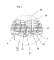
- FIG. 2 A partial view of a preferred embodiment of a second pipetting device is shown in Fig. 2 .
- said processing plate is a multiwell plate with a two-dimensional arrangement of vessels.
- sample vessels used in the method of the present invention are arranged in a linear rack.
- sample vessels comprise stored information relating to their identity and readable by a reader.
- Preferred embodiments of stored information are barcodes storing information or RFID.
- the reader then transfers the information to the control unit.
- the control unit optimizes the allocation of individual samples for individual tests to be carried out with said samples to the nxm allocation of the vessels in the processing plate.
- an optimal use of the processing plates can be achieved by avoiding unnecessary empty vessels in the process plate during the analytical process by optimized sorting and allocation of samples and tests prior to the start of the analytical process. This leads to an optimal throughput according to the requirements of the user and to cost reductions since less consumables are required for a specific number of tests.
- step b) instructions are transferred from said control unit to a first processor for transferring samples with said first pipetting device, and instructions are transferred from said control unit to a second processor for the steps carried out by said second pipetting device.
- a first processor for transferring samples with said first pipetting device
- instructions are transferred from said control unit to a second processor for the steps carried out by said second pipetting device.
- the present invention comprises a 6x8 arrangement of pipette tips.
- Preferred embodiments of pipette tip racks are described hereinafter.
- said pipette tips are replaced in a tip rack in a two dimensional nxm arrangement following step c).
- the advantageous effect described hereinbefore is achieved by the step of assigning any one pipette tip in said pipette tip rack to a specific vessel of said processing plate with a two-dimensional nxm arrangement of vessels.
- a pipette tip located in position ny/mz of the two-dimensional nxm arrangement of the pipette tip rack is used for pipetting a sample to the vessel in position ny/mz of the two-dimensional nxm arrangement of vessels in said processing vessel.
- the plate has a two dimensional nxm arrangement of the vessels
- the pipette rack has a two-dimensional axnxm arrangement of vessels, wherein a is equal or larger than 1.
- a>1 are disclosed herein.
- pipette tips of two types i.e. pipette tips of a larger volume and pipette tips of a smaller volume as disclosed herein are included in the tip rack.
- Preferred embodiments of second pipetting devices comprise process heads with a two-dimensional nxm arrangement of pipetting units.
- both n and m are >1.
- n is between 2 and 8 and m is between 2 and 12.
- the present invention comprises a 6x8 arrangement of pipetting units.
- Pipetting units are understood to comprise interfaces for interacting with a pipette tip. They further comprise an actuator, preferably a pump for aspirating and dispensing liquids.
- the distance between two adjacent sample vessels is different from the distance between two adjacent vessels of the processing plate, and wherein the distance between two adjacent pipetting units of the first pipetting device is adjustable. Preferred embodiments of said first pipetting device are described hereinafter.
- the method additionally comprises the step of analyzing said purified analyte.
- the present invention also relates to an analytical system (440) for processing an analyte, comprising
- First receptacles (1001) are preferably placed in a rack (1002).
- the first position preferably comprises a holder (1003) for rack (1002).
- the first position additionally preferably comprises a holder (1007) for rack (70).
- the position of said pipetting units (702) of the first pipetting device (700) are variable. Preferred embodiments of said first pipetting device (700) are described hereinafter.
- the tip rack (70) comprises pipette tips (3, 4) in a two-dimensional ax(nxm) arrangement.
- a first type (4) and a second type (3) of pipette tips are comprised in the tip rack (70).
- the first type of pipette tips (4) is arranged in a two-dimensional arrangement
- the second type of pipette tips (3) is arranged in the two-dimensional arrangement.
- the first type of pipette tips (4) has a different volume than the second type of pipette tips (3), preferably, the volume of the first type of pipette tips (4) is more than 500 ul, and the volume of the second type of pipette tips (3) is less than 500 ul.
- a 2. More preferably, the volume of the first type of pipette tips is between 0.5 ml and 5 ml, and the colume of the second type of pipette tips is between 0.5 ul to 500 ul.
- embodiments of the invention with more than two types of pipette tips, and thus a >2 are also included in the present invention.
- the analytical system (440) of the present invention comprises a control unit (1006) for allocating sample types and individual tests to individual positions of said processing plate (101).
- said positions are separate cells (401, 402).
- the system additionally comprises a transfer system (480) for transferring said process plate (101) and said rack (70) between first (402) and second (401) positions.
- a transfer system (480) for transferring said process plate (101) and said rack (70) between first (402) and second (401) positions.
- Preferred embodiments of said transfer system (480) are conveyor belts or, more preferably, one or more handler. Preferred embodiments of said handler are described hereinafter.
- said pipette units of said second pipetting device (35) are engaged to pipette tips (3, 4) which were used in the first position (402).
- a preferred embodiment of the system (440) of the present invention additionally comprises a third station (403) comprising a temperature-controlled incubator for incubating said analyte with reagents necessary to obtain a detectable signal. Further preferred embodiments of this system are described hereinafter.
- More optimal control of the allocation of samples and tests to the two-dimensional arrangement is achieved with a first processor (1004) which is comprised in said first position (402) to which said control unit (1006) transfers instructions for allocating sample types and individual tests to specific positions in the two-dimensional arrangement of vessels (103) of the process plate (101), and a second processor (1005) which is comprised in said second position (401) to which said control unit (1006) transfers instructions for allocating sample types and individual tests to specific positions in the two-dimensional arrangement of vessels (103) of the process plate.
- said system additionally comprises a first processor located in said first position, and a second processor located in said second position.
- said first processor (1004) controls said first pipetting device (700) and said second processor (1005) controls said second pipetting device (35).
- the invention relates to a method for isolating and analyzing an analyte that may be present in a fluid sample. Said method comprises the automated steps of
- said pipette tip used in step a) is re-used after step a).
- step a) comprises
- the processing vessel comprises more than one receptacle. More preferably, the processing vessel is a multiwell plate.
- the method preferably additionally comprises the step of
- the washing in step d) comprises aspirating and dispensing the washing buffer with a process head engaged to pipette tips.
- receptacle as used herein relates to a single vessel (or tube) or to a tube comprised in a multi-tube unit, or to a well (or vessel) of a multiwell plate.
- the reacting comprises generating a detectable signal. More preferably, the method additionally comprises the step of detecting a detectable signal.
- reacting as used herein relates to any type of chemical reaction of the analyte with reagents that is necessary to obtain a detectable signal.
- said reacting comprises amplification.
- Amplification may be understood as any type of enhancement of a signal.
- amplification can be a conversion of a molecule by an enzyme, wherein said enzyme is coupled or bound to the analyte, leading to a detectable signal, wherein more signal molecules are formed than analyte molecules are present.
- amplification further relates to nucleic acid amplification, if the analyte is a nucleic acid. This includes both linear, isothermal and exponential amplifications.
- nucleic acid amplification methods are TMA, SDA, NASBA, PCR, including real-time PCR. Such methods are well known to the skilled person.
- the transporting of said rack comprising said pipette tips and said processing vessel to a second positions occurs between a separate first cell of an analytical instrument and a separate second cell, preferably a processing cell, of said analytical system.
- the rack comprises independent chambers to accommodate pipette tips.
- the first type of pipette tips is re-used for the washing in step d).
- the rack additionally comprises a second type of pipette tips.
- a method as hereinbefore described wherein between step d) and e), the analyte is eluted from the magnetic particles.
- a preferred embodiment comprises the transfer of the analyte from said processing vessel, which is preferably a multiwall plate, to a reaction vessel, which is preferably a multiwall plate, with said second type of pipette tips.
- system of the present invention comprises:
- the positions are separate cells.
- the rack transferred by said transfer system preferably comprises pipette tips which were used in the first position.
- the first receptacle is a sample vessel and the second receptacle is a processing vessel. Further preferred is a processing vessel which is a multiwell vessel. Preferred embodiments of said stations are described hereinafter.
- the transport system preferably transfers the receptacle and the rack from the first position to the second separate position.
- the second separate position comprises a magnetic separation station.
- the analytical system additionally preferably comprises an amplification station.
- the transport system of the preferred system comprises a handler constructed and arranged to grip and transport said rack and said processing vessel from a first to a second location within the system. Further preferred handlers are disclosed herein.
- the system is preferably fully automated.
- the automated analyzer further comprises a reaction station disposed in a third location, wherein said reaction station is constructed and arranged to analyze said analyte to obtain a detectable signal.
- a reaction station is a station comprising an incubator.
- said incubator is a temperature-controlled incubator. More preferably, said incubator is held at one constant temperature.
- Another preferred embodiment of an incubator is a thermocycler block.
- a detector for detecting the detectable signal is integrally connected to the reaction station, more preferably to the incubator as hereinbefore described.
- a preferred detector comprises a nucleic acid quantification system for periodic measurement and quantification. More preferably, the detector additionally comprises a nucleic acid detection system which detects the signal and ascertains the presence or absence of the nucleic acid in the reaction receptacle based upon whether or not a signal above a threshold level is detected.
- the automated analyzer additionally comprises a detecting station.
- the automated analyzer further comprises a transport mechanism.
- Said transport mechanism comprises a handler for handling consumables.
- Said handler preferably transports a consumable between stations.
- said transport mechanism is constructed and arranged to transport said sample vessel and said rack from said sample dispensing station to said separation station. Further preferred embodiments of the automated analyzer of the present invention are individual or combined features disclosed herein.
- the analytical apparatus (400) of the present invention comprises at least one module (401) for processing an analyte, said processing comprising pipetting of a liquid.
- the processing module (401) comprises:
- said processing module (401) is a module for isolation and purification of an analyte. Therefore, the term "processing" as used herein is understood to relate to isolation and/or separation and/or capture and/or purification of an analyte.
- said apparatus (400) comprises a module for preparing samples for processing (402).
- said apparatus (400) comprises a module for amplification of said analyte (403).
- said apparatus additionally comprises a module (404) for transferring amplification reagents from a storage receptacle to a receptacle comprising a purified analyte. Further preferred embodiments of said apparatus are as hereinbefore and hereinafter described.
- the present invention also relates to an automated analyzer (400) for use in performing a nucleic acid based amplification reaction, said analyzer comprising a plurality of modules (401, 402, 403).
- One module is a processing module disposed at a first location within the analyzer constructed and arranged to separate a nucleic acid from other material in a sample.
- Said processing module comprises a separation device as herein described.
- the analyzer further comprises an amplification module disposed and arranged at a second location within the analyzer.
- the amplification module comprises a temperature-controlled incubator for incubating the contents of at least one receptacle, preferably of a multiwell plate comprising the separated nucleic acid and one or more amplification reagents for producing an amplification product indicative of the target nucleic acid in the sample.
- module and “cell” are used interchangeably herein.
- a preferred embodiment of an exemplary tip rack is an integral one part tip rack (70) comprising a top surface (71), two opposing short (72) and two opposing long (73) side walls ( Fig. 2 ).
- the tip rack comprises vessels (74, 75) for holding pipette tips (3, 4).
- Said vessels (74, 75) comprise an open top (76) and a closed bottom (77). Any one vessel (74, 75) can hold one tip (3, 4).
- the footprint of the rack (70) preferably comprises a length and width of the base essentially corresponding to ANSI SBS footprint format. More preferably, the length is 127.76mm +/- 0.25 mm, and the width is 85.48 mm +/- 0.25 mm.
- Preferred embodiments of said second embodiment comprise hardware identifiers (6, 7, 39), recesses (37) to engage with counter elements on an analytical instrument to hold down the rack in the instrument as described for the first embodiment of said rack.
- Preferred embodiments also comprise positioning elements (31, 32, 33, 34, 10) as described for the first embodiment of the rack (60).
- the processing plate (101) of the present invention is preferably a 1-component plate. Its top surface (110) comprises multiple vessels (103) ( Fig. 4-6 ). Each vessel has an opening (108) at the top and is closed at the bottom end (112).
- the top surface (110) comprises ribs (104) which are preferably elevated relative to the top surface (110) and surround the openings (108) of the vessels (103). This prevents contamination of the contents of the vessels (103) with droplets of liquid that may fall onto the top surface (110) of the plate (101). Views of a preferred process plate are shown in Figs. 4 to 13 .
- the footprint of the processing plate (101) preferably comprises a length and width of the base corresponding to ANSI SBS footprint format. More preferably, the length is 127.76mm +/-0.25 mm, and the width is 85.48 mm +/- 0.25 mm. Thus, the plate (101) has two opposing shorter side walls (109) and two opposing longer side walls (118).
- the processing plate (101) comprises form locking elements (106) for interacting with a handler (500).
- the processing plate (101) can be gripped, transported and positioned quickly and safely at high speed while maintaining the correct orientation and position.
- the form locking elements (106) for gripping are located within the upper central part, preferably the upper central third of the processing plate (101). This has the advantage that a potential distortion of the processing plate (101) has only a minor effect on the form locking elements (106) and that the handling of the plate (101) is more robust.
- the processing plate (101) preferably comprises hardware-identifiers (102) and (115).
- the hardware identifiers (102) and (115) are unique for the processing plate (101) and different from hardware identifiers of other consumables used in the same system.
- the hardware identifiers (102, 115) preferably comprise ridges (119) and/or recesses (125) on the side walls of the consumables, wherein said pattern of ridges (119) and/or recesses (125) is unique for a specific type of consumable, preferably the processing plate (101). This unique pattern is also referred to herein as a unique "surface geometry".
- the hardware-identifiers (102, 115) ensure that the user can only load the processing plate (101) into the appropriate stacker position of an analytical instrument (126) in the proper orientation.
- guiding elements (116) and (117) are comprised ( Fig. 11 ). They prevent canting of the processing plate (101).
- the guiding elements (116, 117) allow the user to load the processing plates (101) with guiding elements (116, 117) as a stack into an analytical instrument which is then transferred vertically within the instrument in a stacker without canting of the plates.
- a continuous space (121) is located ( Fig. 10, 11 ).
- the space (121) can accommodate magnets (122) or heating devices (128).
- one of the shorter side walls (109) of the vessel (103) comprises an reagent inlet channel (105) which extends to the circumferential rib (104) ( Fig. 4 ).
- the reagents are pipetted onto the reagent inlet channel (105) and drain off the channel (105) into the vessel (103).
- contact between the pipette needle (80) or tip (3, 4) and liquid contained in the vessel is prevented.
- splashes resulting from liquid being directly dispensed into another liquid (215) contained in the vessels (103), which may cause contamination of the pipette needle (80) or tip (3, 4) or neighboring vessels (103) is prevented.
- the shape On the inside, on the bottom of the vessels (111, 112), the shape becomes conical (111) and ends with a spherical bottom (112) ( Fig. 10 ).
- the combination of spherical bottom (112), rounded inside shape (114), conical part (111) and refined surface of the vessels (103) leads to favorable fluidics which facilitate an effective separation and purification of analytes in the processing plate (101).
- the spherical bottom (112) allows an essentially complete use of the separated eluate and a reduction of dead-volume which reduces the carryover of reagents or sample cross-contamination.
- the rim on the base (129) of the processing plate (101) comprises recesses (107) for engagement with latch clips (124) on the processing station (201) or heating device (128) or analytical instrument (126).
- the engagement of the latch clips (124) with the recesses (107) allows positioning and fixation of the processing plate (101) on the processing station (201).
- the presence of the recesses (107) allows the latch force to act on the processing plate (101) almost vertically to the base (129). Thus, only small forces acting sideways can occur. This reduces the occurrence of strain, and, thus, the deformation of the processing plate (101).
- the vertical latch forces can also neutralize any deformations of the processing plate (101) leading to a more precise positioning of the spherical bottoms (111) within the processing station (201).
- the precise interface between the processing plate (101) and the processing station (201) or heating device (128) within an analyzer (126) reduces dead-volumes and also reduces the risk of sample cross-contamination.
- a preferred handler (500) comprises a central part (500a) which is connected to a robotic arm (502).
- the central part (500a) comprises, on two opposite sides, gripper fingers (501).
- the gripper fingers (501) are movable.
- the gripper fingers (501) When engaging with a consumable (60, 70, 101,301,302) comprising form-locking elements (38, 106, 507, 309), as hereinbefore described, the gripper fingers (501) connect with the consumable (60, 70, 101,301,302).
- the gripper fingers (501) are moved towards the consumable (60, 70, 101, 301, 302), in X-direction, interlock with the form locking elements (38, 106, 507, 309), until the gripper fingers (501) reach a stop.
- a form-locked position between handler (500) and consumable (60, 70, 101,301,302) exists.
- the handler (500) connected to the robotic arm (502) can move the consumable (60, 70, 101,301,302) from one position to a second position.
- the gripper fingers (501) move away from the consumable (60, 70, 101,301,302).
- the handler comprises spring-mounted pins (506). Said pins (506) are forced away from the consumable (60, 70, 101,301,302) when the handler (500) is pushed on the consumable (60, 70, 101,301,302).
- the gripper fingers (501) can interact with the form locking elements (38, 106, 507, 309) of the consumable (60, 70, 101,301,302).
- the gripper fingers (501) can move away from the form locking elements (38, 106, 507, 309) of the consumable (60, 70, 101,301,302) ( Fig. 15 a) ).
- the handler (500) also comprises pins (507) which are located sideways of the multiwell plate when the handler (500) is moved downwards on the consumable (60, 70, 101,301,302) prior to gripping. These pins (507) guide the consumable (60, 70, 101,301,302) into the correct position for gripping. Furthermore, said pins (507) prevent the consumable (60, 70, 101,301,302) from getting stuck to the handler (500) when the gripper fingers (501) move away from the consumable (60, 70, 101,301,302) ( Fig. 15 b)
- said form-locking elements (38, 106, 507, 309) are openings (38, 106, 507, 309) in the side walls of the consumable, more preferably the long side of the consumable (60, 70, 101,301,302).
- two openings (38, 106, 507, 309) are located on one side wall, and two openings (38, 106, 507, 309) are located on the opposite side wall.
- At least one module is mounted outside of said frame, wherein the said modules of two adjacent pipetting units are staggered. This again allows achieving an appropriate spacing between said pipetting units.
- the pipetting unit does not comprise frames.
- at least one module is mounted in a staggered fashion on two adjacent pipetting units.
- a preferred shortest distance between said more than one pipette units is 10 mm or shorter. More preferably, the shortest distance between said more than one pipette units is between 10 mm and 1 mm. Further preferred shortest distances are 9 mm, 4.5 mm, 2.25 mm, 1.125 mm.
- the device hereinbefore described additionally comprises a sixth module, which is a sensor module.
- Preferred sensor modules are sensors for initializing or determining the position in Y or Z direction of the pipette unit.
- Preferred sensors for determining the position of the pipette unit in is a ultrasound sensor.
- one side of a pipette unit is connected to said Y-axis transfer mechanism.
- said pipette units additionally comprise ball bearings, wherein said ball bearings of two adjacent pipette units are staggered.
- the present invention further relates to a method of pipetting samples from a first set of vessels holding said samples to a second set of vessels, wherein the distance between adjacent vessels of the first set of vessels is different from the distance between adjacent vessels of the second set of vessels.
- Said method comprises aspirating said samples with pipette tips mounted on a device hereinbefore described, wherein the distance between said pipetting units is adjusted to the distance between said first set of vessels by moving the pipetting units along one axis prior to aspiration. The distance between the pipette units to the distance between said second set of vessels prior to dispensing is then adjusted for dispensing said samples into the second set of vessels.
- said first set of vessels comprises at least two vessels in a linear arrangement.
- said second set of vessels are integrally formed.
- the second set of vessels is only one vessel.
- said second set of vessels comprises a multiwell plate.
- the present invention further relates to a method of isolating and analyzing at least one analyte that may be present in at least one liquid sample in an automated analytical system, comprising the automated steps of providing a first set of vessels comprising said at least one liquid sample to said automated analytical system; aspirating at least a portion of said at least two liquid samples from said first set of vessels with a pipetting device comprising more than one pipetting unit, wherein the distance between said pipetting units is adjusted to the distance between the first set of vessels prior to aspiration; adjusting the distance between said pipetting units to the distance between vessels of a second set of vessels; dispensing said liquid samples into said second set of vessels.
- the method further comprises the steps of combining together a solid support material and one of said fluid samples in a well of said second set of vessels vessel for a period of time and under conditions sufficient to permit said analyte to be immobilized on the solid support material. isolating the solid support material is then isolated from other material present in the fluid sample in a separation station. The analyte is then purified in the separation station by separating the fluid sample from the solid support material and washing the materials one or more times with a wash buffer. Finally, the analyte is analyzed.
- the method comprises at least two liquid samples.
- said analyte is a nucleic acid. More preferably, said device comprises the device hereinbefore described.
- the present invention also relates to an analytical system for isolating an analyte, comprising a module for transferring samples from a first set of vessels to a second set of vessels, wherein said module comprises a pipetting device comprising more than one pipetting units, wherein said pipetting units are movable relative to each other along one axis; and a module for isolating said analyte.
- said analytical system additionally comprises a module for analyzing said analyte.
- a device (700) according to the invention comprising a main frame body (701) and two pipetting units (702 a,b) is shown in Fig. 16 .
- Each pipetting unit (702) comprises two frames (703, 704).
- any one of the pipetting unit (702) comprises an electronic module (705).
- the electronic module (705) of pipetting unit (702 a) is mounted in the lower frame (703)
- the electronic module (705) of pipetting unit (702 b) is mounted in the upper frame (704).
- the Y-axis actuators (717) are also mounted on the pipette units in a staggered fashion.
- the pipetting units also comprise interfaces (706) for interacting with pipette tips (3, 4).
- Fig. 17 shows the two units (702 a, b) as they are moved together, bringing the two pipette tips (3, 4) into close proximity.
- Corresponding modules (eg 705) are arranged in an nonoverlapping way to allow for an optimal spacing between the two pipetting units.
- Fig. 18 a) shows a device (700) with five pipette units (702 a to e) with the staggered mount of different modules (705). Four of the pipette units (702 b to e) are shown with a short distance between each other. The fifth unit (702 a) is shown in a position further away.
- Fig. 18 b) shows a device (700) with eight pipetting units (702), wherein all units (702) are in close proximity to the adjacent units (702) and have needles (80) for pipetting.
- Fig. 19 shows an embodiment of a pipetting device (700) which is only moved in Z-direction.
- a) Two units (702) are fixed in the support (707). To obtain a sufficiently small raster, e.g. a 9 mm raster, the units (702) are mounted in a staggered manner. Modules (710) on the tools (709) as well as modules (705, 711) on the frame part (703) of the pipette unit (702) are staggered to obtain the required distance between the pipette units (702).
- B) shows the pipette units (709 a, b) and the frames (702 a, b) in a disassembled manner.
- Fig. 20 shows the interface to the frame body (701): a) the frame body is a Y-carriage; the pipetting unit (702) comprises an interacting part (712) which can be engaged with a receiving part (713) of the frame body (701) and releasably fixed. b) shows a detail of the interacting part before engagement. c) shows the frame engaged to the frame body.
- Fig. 21 a shows an adaptor plate (714) for fixing the pipette tool (709) to the frame part (710) of the pipette unit (702).
- Other tools (715, 716) may also be attached to said frame part (710).
- b) shows a detail of the pipette tool (709) fixed to the frame part (702).
- the pipette unit may comprise additional modules.
- such modules comprise sensors.
- sensors Several types of sensors and other modules are shown in Fig. 22 a) to c) , eg. a magnet (720), a hallsensor (721), an init-sensor of the Z-drive (723), an init sensor of the Y-drive (722), an ultrasound sensor (724).
- the separation station (230) comprises at least one fixture (231) comprising at least one magnet (232), preferably a number of magnets equal to a number of vessels (103) in a row (123).
- the separation station (230) comprises a number of fixtures (231) equal to the number of rows (123) of the multiwell plate (101) hereinbefore described. More preferably, six fixtures (231) are mounted on the separation station (230). At least one magnet (232) is mounted on one fixture (231). Preferably, the number of magnets (232) equals the number of vessels (103) in one row (123). Most preferably, eight magnets (232) are mounted on one fixture (231).
- one type of magnet (232) is comprised on said fixture (231). More preferably, the magnet (232) is mounted on one side of the which is oriented towards the vessels with which the magnet interacts.
- the fixture (231) is mounted on a base (233).
- said mount is flexible.
- the base (233) comprises springs (234) mounted thereon.
- the number of springs (234) is at least one spring per fixture (231) mounted on said base (233).
- the base further comprises a chamfer (236) which limits the movement of the spring and, consequently, the fixture (231) comprising the magnets (232).
- any one of said springs (234) is constructed and arranged to interact with a fixture (231). More preferably, said spring (234) is a yoke spring. Said interaction controls the horizontal movement of the fixtures (231).
- the separation station (230) comprises a frame (235).
- the base (233) with fixtures (231) is connected to the frame (235) by a moving mechanism as described hereinbefore for the magnets (232) of the first embodiment.
- said base (233) and fixture (231) is constructed and arranged to move vertically (in Z-direction).
- the multiwell plate (101) hereinbefore described is inserted into the separation station (230).
- the fixture (231) comprising the magnets (232) is moved vertically. Any one fixture (232) is, thus, moved into a space (121) between two rows (123) of vessels (103).
- the vertical movement brings the magnets (232) mounted on a fixture (231) into contact with the vessels (103).
- the Z-position is chosen depending on the volume of liquid (215) inside the vessels (103).
- the magnets (232) contact the vessels (103) in a center position (120) where the vessels (103) are of an almost rectangular shape.
- the magnets (232) preferably contact the conical part (111) of the vessels (103).
- a spring is attached to the base (233) of any one frame (231) .
- the spring presses the magnets (232) against the vessels (103). This ensures a contact between magnets (232) and vessels (103) during magnetic separation.
- the magnet (232) contacts the vessel (103) on the side wall (109) located underneath the inlet (105). This has the advantage that liquid which is added by pipetting flows over the sequestered magnetic particles and ensures that particles are resuspended and that all samples in all vessels are treated identically.
- This embodiment is particularly suited to separate a liquid (215) comprised in a multiwell plate (101) as hereinbefore described, from magnetic particles (216) when different levels of liquid (215) are contained in the vessels (103) of said multiwell plate (101).
Landscapes
- Chemical & Material Sciences (AREA)
- Immunology (AREA)
- Health & Medical Sciences (AREA)
- Biochemistry (AREA)
- Life Sciences & Earth Sciences (AREA)
- Analytical Chemistry (AREA)
- Physics & Mathematics (AREA)
- General Health & Medical Sciences (AREA)
- General Physics & Mathematics (AREA)
- Pathology (AREA)
- Chemical Kinetics & Catalysis (AREA)
- Automatic Analysis And Handling Materials Therefor (AREA)
- Sampling And Sample Adjustment (AREA)
Priority Applications (1)
| Application Number | Priority Date | Filing Date | Title |
|---|---|---|---|
| EP11171557.9A EP2402764B1 (fr) | 2010-06-29 | 2011-06-27 | Distribution d'échantillons |
Applications Claiming Priority (2)
| Application Number | Priority Date | Filing Date | Title |
|---|---|---|---|
| EP10167647 | 2010-06-29 | ||
| EP11171557.9A EP2402764B1 (fr) | 2010-06-29 | 2011-06-27 | Distribution d'échantillons |
Publications (2)
| Publication Number | Publication Date |
|---|---|
| EP2402764A1 true EP2402764A1 (fr) | 2012-01-04 |
| EP2402764B1 EP2402764B1 (fr) | 2019-11-27 |
Family
ID=43385698
Family Applications (1)
| Application Number | Title | Priority Date | Filing Date |
|---|---|---|---|
| EP11171557.9A Active EP2402764B1 (fr) | 2010-06-29 | 2011-06-27 | Distribution d'échantillons |
Country Status (3)
| Country | Link |
|---|---|
| US (3) | US8772036B2 (fr) |
| EP (1) | EP2402764B1 (fr) |
| JP (1) | JP5846773B2 (fr) |
Cited By (1)
| Publication number | Priority date | Publication date | Assignee | Title |
|---|---|---|---|---|
| US20150101427A1 (en) * | 2013-10-10 | 2015-04-16 | Hamilton Bonaduz Ag | Movement device comprising a combined individual movement and block movement drive for a plurality of jointly guided movement units |
Families Citing this family (7)
| Publication number | Priority date | Publication date | Assignee | Title |
|---|---|---|---|---|
| US20140011290A1 (en) * | 2007-01-16 | 2014-01-09 | Roche Diagnostics Operations, Inc. | Collection of liquid analytical samples for clinical analytical purpose and device thereof |
| EP2410342B1 (fr) * | 2010-06-29 | 2020-02-19 | F.Hoffmann-La Roche Ag | Dispositif de pipetage avec pointes de pipette mobiles indépendamment |
| JP5846773B2 (ja) * | 2010-06-29 | 2016-01-20 | エフ.ホフマン−ラ ロシュ アーゲーF. Hoffmann−La Roche Aktiengesellschaft | サンプルの分配 |
| CA2976652A1 (fr) * | 2015-02-27 | 2016-09-01 | Hycor Biomedical, Llc | Appareils et procedes pour mettre en suspension et laver le contenu d'une pluralite de plusieurs cuvettes |
| US9623405B2 (en) * | 2015-03-03 | 2017-04-18 | HighRes Biosolutions, Inc. | Pipettor system |
| JP7172745B2 (ja) * | 2019-03-06 | 2022-11-16 | 株式会社Jvcケンウッド | 分析用ユニット、洗浄装置、及び洗浄方法 |
| KR102635367B1 (ko) * | 2023-05-23 | 2024-02-08 | 주식회사 제놀루션 | 검체처리장치 및 검체처리방법 |
Citations (7)
| Publication number | Priority date | Publication date | Assignee | Title |
|---|---|---|---|---|
| JPH08211071A (ja) * | 1994-10-27 | 1996-08-20 | Precision Syst Sci Kk | 自動分析装置及びその方法 |
| WO1999057561A2 (fr) | 1998-05-01 | 1999-11-11 | Gen-Probe Incorporated | Analyseur automatise pour diagnostics et procede correspondant |
| EP0965842A1 (fr) * | 1996-05-20 | 1999-12-22 | Precision System Science Co., Ltd. | Procede et appareil pour commander des particules magnetiques a l'aide d'une machine de pipettage |
| US20040161368A1 (en) * | 2001-05-09 | 2004-08-19 | Jostein Holtlund | Assay system |
| WO2005009202A2 (fr) * | 2003-05-12 | 2005-02-03 | Isis Pharmaceuticals, Inc. | Identification automatique de bioagents |
| US20060081539A1 (en) * | 2002-04-26 | 2006-04-20 | Abbott Laboratories | Structure and method for handling magnetic particles in biological assays |
| EP1712285A1 (fr) * | 2005-04-13 | 2006-10-18 | Fuji Photo Film Co., Ltd. | Dispositif et méthode pour la distribution de fluide at dispositif d'essai utilisant la réfléction totale atténuée |
Family Cites Families (38)
| Publication number | Priority date | Publication date | Assignee | Title |
|---|---|---|---|---|
| US3581575A (en) * | 1969-04-11 | 1971-06-01 | Fisons Ltd | Dispensing apparatus for receiving and discharging a precisely predetermined volume of fluid |
| US4265855A (en) * | 1978-11-03 | 1981-05-05 | Electro-Nucleonics, Inc. | System for performing immunochemical and other analyses involving phase separation |
| US4681742A (en) * | 1984-10-01 | 1987-07-21 | Cetus Corporation | Assay tray |
| US4734261A (en) * | 1985-01-29 | 1988-03-29 | Fuji Photo Film Co., Ltd. | Duplex pipette |
| US4803050A (en) * | 1985-07-22 | 1989-02-07 | Sequoia-Turner Corporation | Method and apparatus for liquid addition and aspiration in automated immunoassay techniques |
| US5306510A (en) * | 1988-01-14 | 1994-04-26 | Cyberlab, Inc. | Automated pipetting system |
| DE3805808A1 (de) | 1988-02-24 | 1989-09-07 | Europ Lab Molekularbiolog | Automatische arbeitsstation fuer mikrobiologische arbeiten |
| US5335481A (en) * | 1993-01-22 | 1994-08-09 | Ward Glen N | Apparatus and method for automatic packaging of pipette tips |
| FI932866A0 (fi) * | 1993-06-21 | 1993-06-21 | Labsystems Oy | Separeringsfoerfarande |
| US5417922A (en) * | 1993-05-14 | 1995-05-23 | Board Of Regents - University Of Nebraska | Specimen carrier |
| EP0644426B1 (fr) * | 1993-09-17 | 2004-05-06 | F. Hoffmann-La Roche Ag | Analyseur comprenant un dispositif pour la suspension de particules, et méthode de suspension |
| JP3115501B2 (ja) * | 1994-06-15 | 2000-12-11 | プレシジョン・システム・サイエンス株式会社 | 分注機を利用した磁性体の脱着制御方法及びこの方法によって処理される各種装置 |
| DE4423878A1 (de) * | 1994-07-07 | 1996-01-11 | Boehringer Mannheim Gmbh | Vorrichtung und Verfahren zum Abscheiden von magnetischen Mikropartikeln |
| JP3481705B2 (ja) * | 1994-12-12 | 2003-12-22 | 株式会社モリテックス | 自動固相抽出装置 |
| JPH0949848A (ja) * | 1995-08-07 | 1997-02-18 | Suzuki Motor Corp | 分注装置 |
| JPH0996643A (ja) * | 1995-09-29 | 1997-04-08 | Suzuki Motor Corp | 酵素免疫反応測定装置 |
| JP2001527642A (ja) * | 1997-01-17 | 2001-12-25 | スミスクライン・ビーチャム・コーポレイション | ビーズを配列するための装置および方法 |
| US6045755A (en) * | 1997-03-10 | 2000-04-04 | Trega Biosciences,, Inc. | Apparatus and method for combinatorial chemistry synthesis |
| US5976470A (en) * | 1998-05-29 | 1999-11-02 | Ontogen Corporation | Sample wash station assembly |
| JP3587066B2 (ja) * | 1998-10-12 | 2004-11-10 | 松下電器産業株式会社 | 自動分注装置 |
| US6235244B1 (en) * | 1998-12-14 | 2001-05-22 | Matrix Technologies Corp. | Uniformly expandable multi-channel pipettor |
| US6497155B1 (en) * | 1999-02-09 | 2002-12-24 | Pharmacopeia, Inc. | Article comprising a particle retrieval device |
| ATE341002T1 (de) * | 1999-02-16 | 2006-10-15 | Applera Corp | Vorrichtung zur handhabung von kügelchen |
| US20020009394A1 (en) * | 1999-04-02 | 2002-01-24 | Hubert Koster | Automated process line |
| WO2001011364A1 (fr) * | 1999-08-09 | 2001-02-15 | Precision System Science Co., Ltd. | Procede d'etiquetage automatique faisant appel a un distributeur automatique, procede de separation automatique d'une substance cible, procede permettant de determiner la sequence de base et systeme de distribution automatique |
| US6451263B1 (en) * | 1999-11-04 | 2002-09-17 | Helena Laboratories Corporation | Pipette adapter |
| WO2002039084A2 (fr) * | 2000-10-25 | 2002-05-16 | Dna Sciences, Inc. | Chargeur d'echantillons de fluides a geometrie variable |
| JP2002189033A (ja) * | 2000-12-22 | 2002-07-05 | Furuno Electric Co Ltd | 分注方法、分注システム、およびチップストッカ装置 |
| EP1354211A1 (fr) | 2001-01-25 | 2003-10-22 | Tecan Trading AG | Dispositif de pipettage |
| US20020106804A1 (en) * | 2001-02-05 | 2002-08-08 | Nippon Laser & Electronics Lab | Method for analyzing reaction test sample using test sample chip |
| JP4016811B2 (ja) | 2002-11-15 | 2007-12-05 | 日立工機株式会社 | 自動分注装置 |
| GB2425498A (en) | 2005-04-25 | 2006-11-01 | Dynal Biotech Asa | A magnetic separation device |
| JP5038004B2 (ja) | 2007-04-12 | 2012-10-03 | キヤノン株式会社 | 分析装置 |
| US8222048B2 (en) * | 2007-11-05 | 2012-07-17 | Abbott Laboratories | Automated analyzer for clinical laboratory |
| US8029742B2 (en) * | 2008-05-05 | 2011-10-04 | Integra Biosciences Corp. | Multi-channel pipettor with repositionable tips |
| EP2192186B1 (fr) | 2008-11-28 | 2016-03-09 | F. Hoffmann-La Roche AG | Système et précédé pour l'extraction automatisée des acides nucléiques |
| JP5846773B2 (ja) * | 2010-06-29 | 2016-01-20 | エフ.ホフマン−ラ ロシュ アーゲーF. Hoffmann−La Roche Aktiengesellschaft | サンプルの分配 |
| SG192678A1 (en) * | 2011-02-10 | 2013-09-30 | Hysitron Inc | Nanomechanical testing system |
-
2011
- 2011-06-24 JP JP2011140587A patent/JP5846773B2/ja active Active
- 2011-06-27 US US13/169,559 patent/US8772036B2/en active Active
- 2011-06-27 EP EP11171557.9A patent/EP2402764B1/fr active Active
-
2014
- 2014-05-23 US US14/285,907 patent/US9383379B2/en active Active
- 2014-05-23 US US14/285,825 patent/US9383378B2/en active Active
Patent Citations (9)
| Publication number | Priority date | Publication date | Assignee | Title |
|---|---|---|---|---|
| JPH08211071A (ja) * | 1994-10-27 | 1996-08-20 | Precision Syst Sci Kk | 自動分析装置及びその方法 |
| JP3652424B2 (ja) * | 1994-10-27 | 2005-05-25 | 日本政策投資銀行 | 自動分析装置及びその方法 |
| EP0965842A1 (fr) * | 1996-05-20 | 1999-12-22 | Precision System Science Co., Ltd. | Procede et appareil pour commander des particules magnetiques a l'aide d'une machine de pipettage |
| WO1999057561A2 (fr) | 1998-05-01 | 1999-11-11 | Gen-Probe Incorporated | Analyseur automatise pour diagnostics et procede correspondant |
| EP2156891A2 (fr) * | 1998-05-01 | 2010-02-24 | Gen-Probe Incorporated | Système et procédé pour incuber le contenu d'une cuve à réaction |
| US20040161368A1 (en) * | 2001-05-09 | 2004-08-19 | Jostein Holtlund | Assay system |
| US20060081539A1 (en) * | 2002-04-26 | 2006-04-20 | Abbott Laboratories | Structure and method for handling magnetic particles in biological assays |
| WO2005009202A2 (fr) * | 2003-05-12 | 2005-02-03 | Isis Pharmaceuticals, Inc. | Identification automatique de bioagents |
| EP1712285A1 (fr) * | 2005-04-13 | 2006-10-18 | Fuji Photo Film Co., Ltd. | Dispositif et méthode pour la distribution de fluide at dispositif d'essai utilisant la réfléction totale atténuée |
Cited By (2)
| Publication number | Priority date | Publication date | Assignee | Title |
|---|---|---|---|---|
| US20150101427A1 (en) * | 2013-10-10 | 2015-04-16 | Hamilton Bonaduz Ag | Movement device comprising a combined individual movement and block movement drive for a plurality of jointly guided movement units |
| US9664263B2 (en) * | 2013-10-10 | 2017-05-30 | Hamilton Bonaduz Ag | Movement device comprising a combined individual movement and block movement drive for a plurality of jointly guided movement units |
Also Published As
| Publication number | Publication date |
|---|---|
| JP2012013697A (ja) | 2012-01-19 |
| US8772036B2 (en) | 2014-07-08 |
| US9383378B2 (en) | 2016-07-05 |
| US9383379B2 (en) | 2016-07-05 |
| JP5846773B2 (ja) | 2016-01-20 |
| US20150050185A1 (en) | 2015-02-19 |
| US20150037896A1 (en) | 2015-02-05 |
| US20120164735A1 (en) | 2012-06-28 |
| EP2402764B1 (fr) | 2019-11-27 |
Similar Documents
| Publication | Publication Date | Title |
|---|---|---|
| US9383379B2 (en) | Sample distribution in a method for isolating analytes in fluid samples in an automated system | |
| US9315801B2 (en) | Method for separating and detecting an analyte | |
| CA2724132C (fr) | Systeme d'amplification avec separation spatiale | |
| CA2724106C (fr) | Plaque et couvercle multipuits | |
| EP2338596B1 (fr) | Plateau pour embouts de pipettes | |
| EP2333557B1 (fr) | Système d'identification de matériel consommable | |
| EP2602626B1 (fr) | Horloge de flux de travail entre les modules | |
| US9958469B2 (en) | Form-locking gripping system | |
| EP2338600A1 (fr) | Positionnement de tête de procédé | |
| EP2363713A1 (fr) | Architecture matérielle pour analyseurs | |
| EP2397859B1 (fr) | Surveillance optique de mélange et de séparation |
Legal Events
| Date | Code | Title | Description |
|---|---|---|---|
| AK | Designated contracting states |
Kind code of ref document: A1 Designated state(s): AL AT BE BG CH CY CZ DE DK EE ES FI FR GB GR HR HU IE IS IT LI LT LU LV MC MK MT NL NO PL PT RO RS SE SI SK SM TR |
|
| AX | Request for extension of the european patent |
Extension state: BA ME |
|
| PUAI | Public reference made under article 153(3) epc to a published international application that has entered the european phase |
Free format text: ORIGINAL CODE: 0009012 |
|
| 17P | Request for examination filed |
Effective date: 20120704 |
|
| STAA | Information on the status of an ep patent application or granted ep patent |
Free format text: STATUS: EXAMINATION IS IN PROGRESS |
|
| 17Q | First examination report despatched |
Effective date: 20170914 |
|
| GRAP | Despatch of communication of intention to grant a patent |
Free format text: ORIGINAL CODE: EPIDOSNIGR1 |
|
| STAA | Information on the status of an ep patent application or granted ep patent |
Free format text: STATUS: GRANT OF PATENT IS INTENDED |
|
| INTG | Intention to grant announced |
Effective date: 20190626 |
|
| GRAS | Grant fee paid |
Free format text: ORIGINAL CODE: EPIDOSNIGR3 |
|
| GRAA | (expected) grant |
Free format text: ORIGINAL CODE: 0009210 |
|
| STAA | Information on the status of an ep patent application or granted ep patent |
Free format text: STATUS: THE PATENT HAS BEEN GRANTED |
|
| AK | Designated contracting states |
Kind code of ref document: B1 Designated state(s): AL AT BE BG CH CY CZ DE DK EE ES FI FR GB GR HR HU IE IS IT LI LT LU LV MC MK MT NL NO PL PT RO RS SE SI SK SM TR |
|
| REG | Reference to a national code |
Ref country code: GB Ref legal event code: FG4D |
|
| REG | Reference to a national code |
Ref country code: CH Ref legal event code: EP |
|
| REG | Reference to a national code |
Ref country code: AT Ref legal event code: REF Ref document number: 1207296 Country of ref document: AT Kind code of ref document: T Effective date: 20191215 |
|
| REG | Reference to a national code |
Ref country code: DE Ref legal event code: R096 Ref document number: 602011063602 Country of ref document: DE |
|
| REG | Reference to a national code |
Ref country code: IE Ref legal event code: FG4D |
|
| REG | Reference to a national code |
Ref country code: NL Ref legal event code: MP Effective date: 20191127 |
|
| REG | Reference to a national code |
Ref country code: LT Ref legal event code: MG4D |
|
| PG25 | Lapsed in a contracting state [announced via postgrant information from national office to epo] |
Ref country code: ES Free format text: LAPSE BECAUSE OF FAILURE TO SUBMIT A TRANSLATION OF THE DESCRIPTION OR TO PAY THE FEE WITHIN THE PRESCRIBED TIME-LIMIT Effective date: 20191127 Ref country code: LV Free format text: LAPSE BECAUSE OF FAILURE TO SUBMIT A TRANSLATION OF THE DESCRIPTION OR TO PAY THE FEE WITHIN THE PRESCRIBED TIME-LIMIT Effective date: 20191127 Ref country code: SE Free format text: LAPSE BECAUSE OF FAILURE TO SUBMIT A TRANSLATION OF THE DESCRIPTION OR TO PAY THE FEE WITHIN THE PRESCRIBED TIME-LIMIT Effective date: 20191127 Ref country code: NO Free format text: LAPSE BECAUSE OF FAILURE TO SUBMIT A TRANSLATION OF THE DESCRIPTION OR TO PAY THE FEE WITHIN THE PRESCRIBED TIME-LIMIT Effective date: 20200227 Ref country code: GR Free format text: LAPSE BECAUSE OF FAILURE TO SUBMIT A TRANSLATION OF THE DESCRIPTION OR TO PAY THE FEE WITHIN THE PRESCRIBED TIME-LIMIT Effective date: 20200228 Ref country code: NL Free format text: LAPSE BECAUSE OF FAILURE TO SUBMIT A TRANSLATION OF THE DESCRIPTION OR TO PAY THE FEE WITHIN THE PRESCRIBED TIME-LIMIT Effective date: 20191127 Ref country code: BG Free format text: LAPSE BECAUSE OF FAILURE TO SUBMIT A TRANSLATION OF THE DESCRIPTION OR TO PAY THE FEE WITHIN THE PRESCRIBED TIME-LIMIT Effective date: 20200227 Ref country code: FI Free format text: LAPSE BECAUSE OF FAILURE TO SUBMIT A TRANSLATION OF THE DESCRIPTION OR TO PAY THE FEE WITHIN THE PRESCRIBED TIME-LIMIT Effective date: 20191127 Ref country code: LT Free format text: LAPSE BECAUSE OF FAILURE TO SUBMIT A TRANSLATION OF THE DESCRIPTION OR TO PAY THE FEE WITHIN THE PRESCRIBED TIME-LIMIT Effective date: 20191127 |
|
| PG25 | Lapsed in a contracting state [announced via postgrant information from national office to epo] |
Ref country code: HR Free format text: LAPSE BECAUSE OF FAILURE TO SUBMIT A TRANSLATION OF THE DESCRIPTION OR TO PAY THE FEE WITHIN THE PRESCRIBED TIME-LIMIT Effective date: 20191127 Ref country code: RS Free format text: LAPSE BECAUSE OF FAILURE TO SUBMIT A TRANSLATION OF THE DESCRIPTION OR TO PAY THE FEE WITHIN THE PRESCRIBED TIME-LIMIT Effective date: 20191127 Ref country code: IS Free format text: LAPSE BECAUSE OF FAILURE TO SUBMIT A TRANSLATION OF THE DESCRIPTION OR TO PAY THE FEE WITHIN THE PRESCRIBED TIME-LIMIT Effective date: 20200327 |
|
| PG25 | Lapsed in a contracting state [announced via postgrant information from national office to epo] |
Ref country code: AL Free format text: LAPSE BECAUSE OF FAILURE TO SUBMIT A TRANSLATION OF THE DESCRIPTION OR TO PAY THE FEE WITHIN THE PRESCRIBED TIME-LIMIT Effective date: 20191127 |
|
| PG25 | Lapsed in a contracting state [announced via postgrant information from national office to epo] |
Ref country code: PT Free format text: LAPSE BECAUSE OF FAILURE TO SUBMIT A TRANSLATION OF THE DESCRIPTION OR TO PAY THE FEE WITHIN THE PRESCRIBED TIME-LIMIT Effective date: 20200419 Ref country code: EE Free format text: LAPSE BECAUSE OF FAILURE TO SUBMIT A TRANSLATION OF THE DESCRIPTION OR TO PAY THE FEE WITHIN THE PRESCRIBED TIME-LIMIT Effective date: 20191127 Ref country code: DK Free format text: LAPSE BECAUSE OF FAILURE TO SUBMIT A TRANSLATION OF THE DESCRIPTION OR TO PAY THE FEE WITHIN THE PRESCRIBED TIME-LIMIT Effective date: 20191127 Ref country code: CZ Free format text: LAPSE BECAUSE OF FAILURE TO SUBMIT A TRANSLATION OF THE DESCRIPTION OR TO PAY THE FEE WITHIN THE PRESCRIBED TIME-LIMIT Effective date: 20191127 Ref country code: RO Free format text: LAPSE BECAUSE OF FAILURE TO SUBMIT A TRANSLATION OF THE DESCRIPTION OR TO PAY THE FEE WITHIN THE PRESCRIBED TIME-LIMIT Effective date: 20191127 |
|
| REG | Reference to a national code |
Ref country code: DE Ref legal event code: R097 Ref document number: 602011063602 Country of ref document: DE |
|
| PG25 | Lapsed in a contracting state [announced via postgrant information from national office to epo] |
Ref country code: SM Free format text: LAPSE BECAUSE OF FAILURE TO SUBMIT A TRANSLATION OF THE DESCRIPTION OR TO PAY THE FEE WITHIN THE PRESCRIBED TIME-LIMIT Effective date: 20191127 Ref country code: SK Free format text: LAPSE BECAUSE OF FAILURE TO SUBMIT A TRANSLATION OF THE DESCRIPTION OR TO PAY THE FEE WITHIN THE PRESCRIBED TIME-LIMIT Effective date: 20191127 |
|
| REG | Reference to a national code |
Ref country code: AT Ref legal event code: MK05 Ref document number: 1207296 Country of ref document: AT Kind code of ref document: T Effective date: 20191127 |
|
| PLBE | No opposition filed within time limit |
Free format text: ORIGINAL CODE: 0009261 |
|
| STAA | Information on the status of an ep patent application or granted ep patent |
Free format text: STATUS: NO OPPOSITION FILED WITHIN TIME LIMIT |
|
| 26N | No opposition filed |
Effective date: 20200828 |
|
| PG25 | Lapsed in a contracting state [announced via postgrant information from national office to epo] |
Ref country code: PL Free format text: LAPSE BECAUSE OF FAILURE TO SUBMIT A TRANSLATION OF THE DESCRIPTION OR TO PAY THE FEE WITHIN THE PRESCRIBED TIME-LIMIT Effective date: 20191127 Ref country code: AT Free format text: LAPSE BECAUSE OF FAILURE TO SUBMIT A TRANSLATION OF THE DESCRIPTION OR TO PAY THE FEE WITHIN THE PRESCRIBED TIME-LIMIT Effective date: 20191127 Ref country code: SI Free format text: LAPSE BECAUSE OF FAILURE TO SUBMIT A TRANSLATION OF THE DESCRIPTION OR TO PAY THE FEE WITHIN THE PRESCRIBED TIME-LIMIT Effective date: 20191127 |
|
| PG25 | Lapsed in a contracting state [announced via postgrant information from national office to epo] |
Ref country code: MC Free format text: LAPSE BECAUSE OF FAILURE TO SUBMIT A TRANSLATION OF THE DESCRIPTION OR TO PAY THE FEE WITHIN THE PRESCRIBED TIME-LIMIT Effective date: 20191127 Ref country code: IT Free format text: LAPSE BECAUSE OF FAILURE TO SUBMIT A TRANSLATION OF THE DESCRIPTION OR TO PAY THE FEE WITHIN THE PRESCRIBED TIME-LIMIT Effective date: 20191127 |
|
| PG25 | Lapsed in a contracting state [announced via postgrant information from national office to epo] |
Ref country code: LU Free format text: LAPSE BECAUSE OF NON-PAYMENT OF DUE FEES Effective date: 20200627 |
|
| REG | Reference to a national code |
Ref country code: BE Ref legal event code: MM Effective date: 20200630 |
|
| PG25 | Lapsed in a contracting state [announced via postgrant information from national office to epo] |
Ref country code: IE Free format text: LAPSE BECAUSE OF NON-PAYMENT OF DUE FEES Effective date: 20200627 |
|
| PG25 | Lapsed in a contracting state [announced via postgrant information from national office to epo] |
Ref country code: BE Free format text: LAPSE BECAUSE OF NON-PAYMENT OF DUE FEES Effective date: 20200630 |
|
| PG25 | Lapsed in a contracting state [announced via postgrant information from national office to epo] |
Ref country code: TR Free format text: LAPSE BECAUSE OF FAILURE TO SUBMIT A TRANSLATION OF THE DESCRIPTION OR TO PAY THE FEE WITHIN THE PRESCRIBED TIME-LIMIT Effective date: 20191127 Ref country code: MT Free format text: LAPSE BECAUSE OF FAILURE TO SUBMIT A TRANSLATION OF THE DESCRIPTION OR TO PAY THE FEE WITHIN THE PRESCRIBED TIME-LIMIT Effective date: 20191127 Ref country code: CY Free format text: LAPSE BECAUSE OF FAILURE TO SUBMIT A TRANSLATION OF THE DESCRIPTION OR TO PAY THE FEE WITHIN THE PRESCRIBED TIME-LIMIT Effective date: 20191127 |
|
| PG25 | Lapsed in a contracting state [announced via postgrant information from national office to epo] |
Ref country code: MK Free format text: LAPSE BECAUSE OF FAILURE TO SUBMIT A TRANSLATION OF THE DESCRIPTION OR TO PAY THE FEE WITHIN THE PRESCRIBED TIME-LIMIT Effective date: 20191127 |
|
| PGFP | Annual fee paid to national office [announced via postgrant information from national office to epo] |
Ref country code: FR Payment date: 20230509 Year of fee payment: 13 Ref country code: DE Payment date: 20230509 Year of fee payment: 13 |
|
| PGFP | Annual fee paid to national office [announced via postgrant information from national office to epo] |
Ref country code: GB Payment date: 20230510 Year of fee payment: 13 Ref country code: CH Payment date: 20230701 Year of fee payment: 13 |