EP2405836B1 - Interspinous process implant and fusion cage spacer - Google Patents
Interspinous process implant and fusion cage spacer Download PDFInfo
- Publication number
- EP2405836B1 EP2405836B1 EP09798981.8A EP09798981A EP2405836B1 EP 2405836 B1 EP2405836 B1 EP 2405836B1 EP 09798981 A EP09798981 A EP 09798981A EP 2405836 B1 EP2405836 B1 EP 2405836B1
- Authority
- EP
- European Patent Office
- Prior art keywords
- implant
- spinous processes
- recited
- spinal implant
- anchor
- Prior art date
- Legal status (The legal status is an assumption and is not a legal conclusion. Google has not performed a legal analysis and makes no representation as to the accuracy of the status listed.)
- Active
Links
- 239000007943 implant Substances 0.000 title claims description 173
- 238000000034 method Methods 0.000 title claims description 129
- 125000006850 spacer group Chemical group 0.000 title claims description 9
- 230000004927 fusion Effects 0.000 title description 6
- 238000003780 insertion Methods 0.000 claims description 40
- 230000037431 insertion Effects 0.000 claims description 40
- 230000033001 locomotion Effects 0.000 claims description 28
- 210000003484 anatomy Anatomy 0.000 claims description 8
- 230000007246 mechanism Effects 0.000 claims description 4
- 239000000463 material Substances 0.000 description 12
- 210000000988 bone and bone Anatomy 0.000 description 10
- 238000009434 installation Methods 0.000 description 8
- 208000005198 spinal stenosis Diseases 0.000 description 8
- 210000000278 spinal cord Anatomy 0.000 description 7
- 238000002513 implantation Methods 0.000 description 6
- 239000004696 Poly ether ether ketone Substances 0.000 description 4
- 229920001971 elastomer Polymers 0.000 description 4
- 239000000806 elastomer Substances 0.000 description 4
- 229920002530 polyetherether ketone Polymers 0.000 description 4
- 210000004872 soft tissue Anatomy 0.000 description 4
- 238000001356 surgical procedure Methods 0.000 description 4
- 210000001519 tissue Anatomy 0.000 description 4
- 208000002193 Pain Diseases 0.000 description 3
- 229910001069 Ti alloy Inorganic materials 0.000 description 3
- 239000000919 ceramic Substances 0.000 description 3
- 239000002131 composite material Substances 0.000 description 3
- 230000006835 compression Effects 0.000 description 3
- 238000007906 compression Methods 0.000 description 3
- 230000006837 decompression Effects 0.000 description 3
- 230000002401 inhibitory effect Effects 0.000 description 3
- 230000006641 stabilisation Effects 0.000 description 3
- 238000011105 stabilization Methods 0.000 description 3
- 239000000126 substance Substances 0.000 description 3
- 229910045601 alloy Inorganic materials 0.000 description 2
- 239000000956 alloy Substances 0.000 description 2
- 238000005452 bending Methods 0.000 description 2
- 238000003384 imaging method Methods 0.000 description 2
- 206010025005 lumbar spinal stenosis Diseases 0.000 description 2
- 238000012978 minimally invasive surgical procedure Methods 0.000 description 2
- 229910001000 nickel titanium Inorganic materials 0.000 description 2
- HLXZNVUGXRDIFK-UHFFFAOYSA-N nickel titanium Chemical compound [Ti].[Ti].[Ti].[Ti].[Ti].[Ti].[Ti].[Ti].[Ti].[Ti].[Ti].[Ni].[Ni].[Ni].[Ni].[Ni].[Ni].[Ni].[Ni].[Ni].[Ni].[Ni].[Ni].[Ni].[Ni] HLXZNVUGXRDIFK-UHFFFAOYSA-N 0.000 description 2
- 238000002360 preparation method Methods 0.000 description 2
- 239000012858 resilient material Substances 0.000 description 2
- 238000010079 rubber tapping Methods 0.000 description 2
- 229910001285 shape-memory alloy Inorganic materials 0.000 description 2
- 210000001032 spinal nerve Anatomy 0.000 description 2
- 230000008961 swelling Effects 0.000 description 2
- 208000024891 symptom Diseases 0.000 description 2
- 238000013519 translation Methods 0.000 description 2
- 238000003466 welding Methods 0.000 description 2
- 208000005298 acute pain Diseases 0.000 description 1
- 238000004873 anchoring Methods 0.000 description 1
- 239000000560 biocompatible material Substances 0.000 description 1
- 239000012620 biological material Substances 0.000 description 1
- 239000003246 corticosteroid Substances 0.000 description 1
- 230000001186 cumulative effect Effects 0.000 description 1
- 230000000991 decompressive effect Effects 0.000 description 1
- 230000001419 dependent effect Effects 0.000 description 1
- 238000011161 development Methods 0.000 description 1
- 230000018109 developmental process Effects 0.000 description 1
- 238000006073 displacement reaction Methods 0.000 description 1
- 230000000694 effects Effects 0.000 description 1
- 239000013013 elastic material Substances 0.000 description 1
- 239000013536 elastomeric material Substances 0.000 description 1
- 238000002594 fluoroscopy Methods 0.000 description 1
- 238000002347 injection Methods 0.000 description 1
- 239000007924 injection Substances 0.000 description 1
- 238000012966 insertion method Methods 0.000 description 1
- 238000012977 invasive surgical procedure Methods 0.000 description 1
- 238000002684 laminectomy Methods 0.000 description 1
- 210000003041 ligament Anatomy 0.000 description 1
- 208000018883 loss of balance Diseases 0.000 description 1
- 238000012423 maintenance Methods 0.000 description 1
- 229910052751 metal Inorganic materials 0.000 description 1
- 239000002184 metal Substances 0.000 description 1
- 238000013508 migration Methods 0.000 description 1
- 230000005012 migration Effects 0.000 description 1
- 210000005036 nerve Anatomy 0.000 description 1
- 230000007935 neutral effect Effects 0.000 description 1
- 229940021182 non-steroidal anti-inflammatory drug Drugs 0.000 description 1
- 238000012148 non-surgical treatment Methods 0.000 description 1
- 231100000862 numbness Toxicity 0.000 description 1
- 238000002355 open surgical procedure Methods 0.000 description 1
- 230000011164 ossification Effects 0.000 description 1
- 238000012856 packing Methods 0.000 description 1
- 229920001296 polysiloxane Polymers 0.000 description 1
- 230000000750 progressive effect Effects 0.000 description 1
- 230000001737 promoting effect Effects 0.000 description 1
- 230000000717 retained effect Effects 0.000 description 1
- 210000003625 skull Anatomy 0.000 description 1
- 239000007787 solid Substances 0.000 description 1
- 210000000273 spinal nerve root Anatomy 0.000 description 1
- 230000000087 stabilizing effect Effects 0.000 description 1
- 239000010935 stainless steel Substances 0.000 description 1
- 229910001220 stainless steel Inorganic materials 0.000 description 1
- 229920001169 thermoplastic Polymers 0.000 description 1
- 239000004416 thermosoftening plastic Substances 0.000 description 1
- 238000011282 treatment Methods 0.000 description 1
Images


Classifications
-
- A—HUMAN NECESSITIES
- A61—MEDICAL OR VETERINARY SCIENCE; HYGIENE
- A61B—DIAGNOSIS; SURGERY; IDENTIFICATION
- A61B17/00—Surgical instruments, devices or methods, e.g. tourniquets
- A61B17/56—Surgical instruments or methods for treatment of bones or joints; Devices specially adapted therefor
- A61B17/58—Surgical instruments or methods for treatment of bones or joints; Devices specially adapted therefor for osteosynthesis, e.g. bone plates, screws, setting implements or the like
- A61B17/68—Internal fixation devices, including fasteners and spinal fixators, even if a part thereof projects from the skin
- A61B17/70—Spinal positioners or stabilisers ; Bone stabilisers comprising fluid filler in an implant
- A61B17/7071—Implants for expanding or repairing the vertebral arch or wedged between laminae or pedicles; Tools therefor
-
- A—HUMAN NECESSITIES
- A61—MEDICAL OR VETERINARY SCIENCE; HYGIENE
- A61B—DIAGNOSIS; SURGERY; IDENTIFICATION
- A61B17/00—Surgical instruments, devices or methods, e.g. tourniquets
- A61B17/56—Surgical instruments or methods for treatment of bones or joints; Devices specially adapted therefor
- A61B17/58—Surgical instruments or methods for treatment of bones or joints; Devices specially adapted therefor for osteosynthesis, e.g. bone plates, screws, setting implements or the like
- A61B17/68—Internal fixation devices, including fasteners and spinal fixators, even if a part thereof projects from the skin
- A61B17/70—Spinal positioners or stabilisers ; Bone stabilisers comprising fluid filler in an implant
- A61B17/7062—Devices acting on, attached to, or simulating the effect of, vertebral processes, vertebral facets or ribs ; Tools for such devices
-
- A—HUMAN NECESSITIES
- A61—MEDICAL OR VETERINARY SCIENCE; HYGIENE
- A61B—DIAGNOSIS; SURGERY; IDENTIFICATION
- A61B17/00—Surgical instruments, devices or methods, e.g. tourniquets
- A61B17/00234—Surgical instruments, devices or methods, e.g. tourniquets for minimally invasive surgery
-
- A—HUMAN NECESSITIES
- A61—MEDICAL OR VETERINARY SCIENCE; HYGIENE
- A61B—DIAGNOSIS; SURGERY; IDENTIFICATION
- A61B17/00—Surgical instruments, devices or methods, e.g. tourniquets
- A61B17/56—Surgical instruments or methods for treatment of bones or joints; Devices specially adapted therefor
- A61B17/58—Surgical instruments or methods for treatment of bones or joints; Devices specially adapted therefor for osteosynthesis, e.g. bone plates, screws, setting implements or the like
- A61B17/68—Internal fixation devices, including fasteners and spinal fixators, even if a part thereof projects from the skin
- A61B17/70—Spinal positioners or stabilisers ; Bone stabilisers comprising fluid filler in an implant
- A61B17/7062—Devices acting on, attached to, or simulating the effect of, vertebral processes, vertebral facets or ribs ; Tools for such devices
- A61B17/7065—Devices with changeable shape, e.g. collapsible or having retractable arms to aid implantation; Tools therefor
-
- A—HUMAN NECESSITIES
- A61—MEDICAL OR VETERINARY SCIENCE; HYGIENE
- A61B—DIAGNOSIS; SURGERY; IDENTIFICATION
- A61B17/00—Surgical instruments, devices or methods, e.g. tourniquets
- A61B17/56—Surgical instruments or methods for treatment of bones or joints; Devices specially adapted therefor
- A61B17/58—Surgical instruments or methods for treatment of bones or joints; Devices specially adapted therefor for osteosynthesis, e.g. bone plates, screws, setting implements or the like
- A61B17/68—Internal fixation devices, including fasteners and spinal fixators, even if a part thereof projects from the skin
- A61B17/70—Spinal positioners or stabilisers ; Bone stabilisers comprising fluid filler in an implant
- A61B17/7062—Devices acting on, attached to, or simulating the effect of, vertebral processes, vertebral facets or ribs ; Tools for such devices
- A61B17/7067—Devices bearing against one or more spinous processes and also attached to another part of the spine; Tools therefor
-
- A—HUMAN NECESSITIES
- A61—MEDICAL OR VETERINARY SCIENCE; HYGIENE
- A61B—DIAGNOSIS; SURGERY; IDENTIFICATION
- A61B17/00—Surgical instruments, devices or methods, e.g. tourniquets
- A61B17/56—Surgical instruments or methods for treatment of bones or joints; Devices specially adapted therefor
- A61B17/58—Surgical instruments or methods for treatment of bones or joints; Devices specially adapted therefor for osteosynthesis, e.g. bone plates, screws, setting implements or the like
- A61B17/68—Internal fixation devices, including fasteners and spinal fixators, even if a part thereof projects from the skin
- A61B17/70—Spinal positioners or stabilisers ; Bone stabilisers comprising fluid filler in an implant
- A61B17/7062—Devices acting on, attached to, or simulating the effect of, vertebral processes, vertebral facets or ribs ; Tools for such devices
- A61B17/7068—Devices comprising separate rigid parts, assembled in situ, to bear on each side of spinous processes; Tools therefor
-
- A—HUMAN NECESSITIES
- A61—MEDICAL OR VETERINARY SCIENCE; HYGIENE
- A61B—DIAGNOSIS; SURGERY; IDENTIFICATION
- A61B17/00—Surgical instruments, devices or methods, e.g. tourniquets
- A61B17/56—Surgical instruments or methods for treatment of bones or joints; Devices specially adapted therefor
- A61B17/58—Surgical instruments or methods for treatment of bones or joints; Devices specially adapted therefor for osteosynthesis, e.g. bone plates, screws, setting implements or the like
- A61B17/68—Internal fixation devices, including fasteners and spinal fixators, even if a part thereof projects from the skin
- A61B17/70—Spinal positioners or stabilisers ; Bone stabilisers comprising fluid filler in an implant
- A61B17/7074—Tools specially adapted for spinal fixation operations other than for bone removal or filler handling
-
- A—HUMAN NECESSITIES
- A61—MEDICAL OR VETERINARY SCIENCE; HYGIENE
- A61B—DIAGNOSIS; SURGERY; IDENTIFICATION
- A61B17/00—Surgical instruments, devices or methods, e.g. tourniquets
- A61B17/56—Surgical instruments or methods for treatment of bones or joints; Devices specially adapted therefor
- A61B17/58—Surgical instruments or methods for treatment of bones or joints; Devices specially adapted therefor for osteosynthesis, e.g. bone plates, screws, setting implements or the like
- A61B17/88—Osteosynthesis instruments; Methods or means for implanting or extracting internal or external fixation devices
-
- A—HUMAN NECESSITIES
- A61—MEDICAL OR VETERINARY SCIENCE; HYGIENE
- A61B—DIAGNOSIS; SURGERY; IDENTIFICATION
- A61B17/00—Surgical instruments, devices or methods, e.g. tourniquets
- A61B17/56—Surgical instruments or methods for treatment of bones or joints; Devices specially adapted therefor
- A61B2017/564—Methods for bone or joint treatment
-
- A—HUMAN NECESSITIES
- A61—MEDICAL OR VETERINARY SCIENCE; HYGIENE
- A61F—FILTERS IMPLANTABLE INTO BLOOD VESSELS; PROSTHESES; DEVICES PROVIDING PATENCY TO, OR PREVENTING COLLAPSING OF, TUBULAR STRUCTURES OF THE BODY, e.g. STENTS; ORTHOPAEDIC, NURSING OR CONTRACEPTIVE DEVICES; FOMENTATION; TREATMENT OR PROTECTION OF EYES OR EARS; BANDAGES, DRESSINGS OR ABSORBENT PADS; FIRST-AID KITS
- A61F2/00—Filters implantable into blood vessels; Prostheses, i.e. artificial substitutes or replacements for parts of the body; Appliances for connecting them with the body; Devices providing patency to, or preventing collapsing of, tubular structures of the body, e.g. stents
- A61F2/02—Prostheses implantable into the body
- A61F2/30—Joints
- A61F2/44—Joints for the spine, e.g. vertebrae, spinal discs
- A61F2/4455—Joints for the spine, e.g. vertebrae, spinal discs for the fusion of spinal bodies, e.g. intervertebral fusion of adjacent spinal bodies, e.g. fusion cages
- A61F2/4465—Joints for the spine, e.g. vertebrae, spinal discs for the fusion of spinal bodies, e.g. intervertebral fusion of adjacent spinal bodies, e.g. fusion cages having a circular or kidney shaped cross-section substantially perpendicular to the axis of the spine
Definitions
- the subject invention is directed to spinal implants, and more particularly, to an interspinous process implant for spinal stabilization, for percutaneous placement in a target interspinous process space, which can also serve as a fusion cage spacer to treat lumbar spinal stenosis.
- the spine consists of a column of twenty-four vertebrae that extend from the skull to the hips. Discs of soft tissue are disposed between adjacent vertebrae. The vertebrae provide support for the head and body, while the discs act as cushions. In addition, the spine encloses and protects the spinal cord, defining a bony channel around the spinal cord, called the spinal canal. There is normally a space between the spinal cord and the borders of the spinal canal so that the spinal cord and the nerves associated therewith are not pinched.
- Non-surgical treatments for spinal stenosis include non-steroidal anti-inflammatory drugs to reduce the swelling and pain, and corticosteroid injections to reduce swelling and treat acute pain. While some patients may experience relief from symptoms of spinal stenosis with such treatments, many do not, and thus turn to surgical treatment.
- the most common surgical procedure for treating spinal stenosis is decompressive laminectomy, which involves removal of parts of the vertebrae. The goal of the procedure is to relieve pressure on the spinal cord and nerves by increasing the area of the spinal canal.
- Interspinous process decompression is a less invasive surgical procedure for treating spinal stenosis. With IPD surgery, there is no removal of bone or soft tissue. Instead, an implant or spacer device is positioned behind the spinal cord or nerves between the interspinous processes that protrude from the vertebrae in the lower back.
- a well-known implant used for performing IPD surgery is the X-STOP® device, which is described in U.S. Patent No. 6,419,676 . However implantation of the X-STOP® device still requires an incision to access the spinal column to deploy the X-STOP® device.
- US 2006/264938 A1 discloses a spinal implant according to preamble part of claim 1.
- the invention is directed to a spinal implant having an elongated body dimensioned and configured to function as a spacer, for placement in a target interspinous process space, between two adjacent spinous processes, a distal anchor associated with a distal end of the body, and a proximal anchor mounted for longitudinal movement along the body between a first position spaced apart from the distal anchor and a second position approximated with the distal anchor, adapted to compress the two adjacent spinous processes, in conjunction with the distal anchor.
- the proximal anchor can include an axially slideable plate.
- the elongated body can be provided with threads at least on a distal portion thereof for facilitating engagement with bony anatomical structures.
- the proximal anchor can include a plurality of circumferentially spaced apart distally facing spikes for engaging the spinous processes when the distal anchor and the proximal anchor are approximated.
- the body and proximal anchor can be threadedly associated with one another to facilitate longitudinal movement of the proximal anchor along the body between the first and second positions.
- the body can be at least partially hollow and include a plurality of openings for permitting tissue ingrowth.
- the distal anchor is provided with a tapered head portion, which can be configured to gradually distract the two adjacent spinous processes during insertion therebetween.
- the shape of the body can ease insertion of the implant in-between the adjacent spinous processes after distraction thereof by a separate instrument or instruments.
- the distal anchor can include a plurality of radially-deployable blades adapted for engaging adjacent spinous processes.
- the body can be provided with an internal chamber in which the plurality of radially-deployable blades are stowed prior to deployment thereof.
- the plurality of radially-deployable blades can be hinged by a common annular pivot member. Alternatively, the plurality of radially-deployable blades can be hinged by a common linear pivot member.
- the spinal implant can further include an internal plunger adapted for deploying the plurality of radially-deployable blades, by way of a camming mechanism.
- the distal anchor can be provided in either a normally expanded or otherwise deployed condition, or alternatively, in a normally contracted or otherwise stowed condition.
- normally means that the implant, absent externally-applied forces, maintains that condition.
- the distal anchor includes a tapered head, wherein the tapered head has a maximum diameter that is, in its neutral state, greater than a diameter of the elongated body.
- the tapered head has a plurality of circumferentially spaced apart proximally-facing spikes for engaging the spinous processes when the distal anchor and the proximal anchor are mutually approximated.
- the tapered head can have a trailing skirt section adapted and configured for movement between a radially expanded condition and a radially compressed condition as the head is inserted between the two adjacent spinous processes.
- the trailing skirt section of the head can include a plurality of circumferentially spaced apart hinged pleats that are biased into the radially expanded condition. Alternatively, these pleats can be biased in a radially contracted condition. The pleats can be biased by spring elements.
- the spinal implant has an elongated body dimensioned and configured to function as a spacer, for placement in a target interspinous process space, between two adjacent spinous processes, the body having a tapered head portion, configured to gradually distract the two adjacent spinous processes during insertion therebetween, a distal anchor associated with a distal end of the body, the distal anchor having a plurality of deployable blades adapted to engage a first side of the two adjacent spinous processes, and a proximal anchor mounted for longitudinal movement along the body between a first position spaced apart from the distal anchor and a second position approximated with the distal anchor, adapted to engage a second side of the two adjacent spinous processes.
- the body can maintain distraction performed by another instrument, prior to insertion of the implant.
- a method of percutaneously performing interspinous process decompression comprising the steps of providing a spinal implant having an elongated body dimensioned and configured to function as a spacer, for placement in a target interspinous process space, between two adjacent spinous processes, a distal anchor associated with a distal end of the body, and a proximal anchor mounted for longitudinal movement along the body between a first position spaced apart from the distal anchor and a second position approximated with the distal anchor, adapted to compress the two adjacent spinous processes, in conjunction with the distal anchor, forming an incision in a patient's skin, lateral from a target interspinous process space, in which the implant is to be placed, inserting a stylet through the incision, laterally to the target interspinous process space, using an internal imaging technique, to form an entry path, inserting one or more dilators, sequentially, along the entry path to dilate soft tissues between the incision and the target interspinous process space, inserting a slee
- a tap can be used after the step of inserting the sleeve.
- the tap can be a graduated-type tap, the diameter of which increasing toward the proximal end thereof.
- threads are cut into the adjacent spinous processes.
- the tap is graduated, the adjacent spinous processes are gradually mutually distracted during advancement of the tap.
- the surgeon can determine the size of the implant to insert. In such an arrangement, the subject implant maintains distraction performed by the tap, and does not necessarily perform distraction.
- the advancing step can include rotating the implant along a longitudinal axis thereof, to effect axial advancement of the implant by way of threads formed on an outer surface thereof.
- interspinous implant constructed in accordance with a preferred embodiment of the subject invention and designated generally by reference numeral 10.
- the implant 10 is particularly well adapted for use in performing minimally invasive surgical procedures for treating spinal stenosis, including, for example, interspinous process decompression (IPD).
- IPD interspinous process decompression
- the implant 10 of the subject invention can be used in other spinal procedures as well, including, but not limited to as an adjunct to spinal fusion procedures, or as a spinal stabilization device.
- the interspinous process implant of the subject invention is well adapted for percutaneous insertion, and thus overcomes many of the drawbacks of prior art devices presently used in IPD procedures. That is, the implant 10 is dimensioned and configured for introduction and placement through a small skin incision rather than in an open surgical procedure involving a cut down of tissue, as will be described in more detail hereinbelow.
- the interspinous process implant 10 includes an elongated threaded body portion 12 which can be configured as a solid element or alternatively can be at least partially hollow, and which may include a plurality of longitudinal openings 14 to permit insertion of demineralized bone or another type of osteogenesis-promoting substances or fusion adjunct material, and also promote the ingrowth of bone.
- the implant 10 further includes a tapered or conical head portion 16, which is associated with a distal end of the body portion 12.
- the head portion 16 can be dimensioned and configured to progressively distract two adjacent spinous processes 381a and 381b as the implant 10 is advanced therebetween. It is to be understood, however, that the head portion 16 facilitates insertion of the implant, when distraction is initially performed by a separate instrument.
- the elongated body portion 12 can alternatively be provided without threads, in accordance with an alternative aspect of the invention.
- the head portion 16 can be attached to the body portion in any suitable manner, including mechanical fasteners, mechanical interlock, welding or the like.
- an axial screw element is provided, although an internal threaded connection can be provided, for example.
- the tapered head 16 of implant 10 is included in a distal anchor portion configured with a trailing skirt section 18.
- the skirt section 18, as embodied, is a dynamic structure formed from a plurality of circumferentially spaced apart pleats 20.
- the pleats 20 can be hinged, and generally arcuate in configuration. Hinging can be accomplished by way of a defined line of weakness in the material, so as to form a "living hinge," or alternatively can be a conventional hinge with a separate pivot. Alternatively still, the necessary deflection of the pleats 20 can be accomplished without a defined hinge, utilizing only the cumulative bending of the pleats 20 along their length. Further, the pleats 20 can be embodied in shapes other than those having an arcuate configuration, such as a generally rectangular parallelepiped, for example.
- the head portion 16 and trailing skirt section 18 have helical threads 22 so as to ease progressive advancement of the head portion 16 and skirt section 18 between the two adjacent bony spinous processes 381a and 381b during insertion therethrough.
- the threads 22 serve to draw the implant 10 into the target interspinous process space 382, defined by the adjacent spinous processes 381a, 381b.
- the helical threads 22 can be any of a variety of suitable forms, such as, for example, cutting threads or box threads.
- the tapered head portion 16 and skirt section 18 can be provided without any threads.
- an integral tap chamfer can be incorporated into the threads, if so-desired.
- the head portion 16 of the implant 10 can be advanced between the two adjacent spinous processes 381a and 381b by application of a generally axially directed force.
- each of the arcuate pleats 20 of the skirt section 18 are biased into a radially expanded condition shown in Figure 1 by coiled biasing springs 25.
- the coiled biasing springs 25 are supported on guide pins 26 that are retained in body portion 12 by heads 28.
- the heads 28 of the guide pins 26 act to limit the extent to which the arcuate pleats 20 of skirt section 18 can extend.
- alternative biasing mechanisms can be used to bias the pleats 20 into an expanded condition, including but not limited to a provision of elastic material, such as an elastomer.
- Such a material can be a bio-compatible silicone, for example.
- the pleats 20 are adapted and configured for movement between a (first) radially expanded condition shown in Figures 1-3 and 5 and a (second) radially compressed condition shown, for example, in Figure 4 .
- a sheath (not illustrated) can be provided over the structure of the head portion 16, such as a thin layer of a biocompatible elastomer, to maintain a continuous surface while permitting flexibility between the pleats.
- webs or similar elements can be provided between adjacent pleats 20.
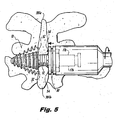
- the implant device 10 further includes a proximal anchor portion 30 that is operatively associated with the threaded body 12 in such a manner so as to enable the longitudinal movement of the anchor portion 30 along the length of body 12 between a first position, spaced from the head portion 16 ( e . g ., Figure 3 ) and second position, approximated with the head portion 16 ( e . g ., Figure 5 ).
- the operative connection between the body portion 12 and the proximal anchor 30 can be accomplished in a variety of ways including a direct threaded engagement between the proximal anchor 30 and the body 12 or through the use of a captured threaded nut that permits the proximal anchor 30 to translate longitudinally along the threaded body portion 12 without rotating about the axis of the body portion 12, such as by providing one or more interfacing flat regions 17a, 17b.
- the proximal surfaces of the arcuate pleats 20 of the trailing skirt section 18 are provided with proximally-directed spikes 24 adapted and configured to engage the bony anatomy of the spinous processes 381a and 381b, when the head portion 16 and the anchor portion 30 are mutually approximated about the spinous processes 381a and 381b.
- the distal surface of the proximal anchor 30 can include a plurality of circumferentially spaced, distally facing spikes 34 for engaging the bony spinous processes 381 a and 381b when the head portion 16 and the anchor portion 30 are mutually approximated into the position shown in Figure 5 .
- the spikes 34 are not limited to any particular shape, but can be generally conical, pyramidal or tetrahedral, for example. Alternatively, the spikes can be truncated versions of such shapes.
- the pleats 20 of the skirt section 18 are urged into a compressed condition, against the bias of the coiled springs 25, or alternative biasing elements.
- the pleats 20 can compress so as to not extend beyond the diameter of the body 12, if necessary.
- the skirt section 18 is beyond the distracted spinous processes 381a, 381b, the pleats 20 are urged back into their normally expanded position under the bias of the springs'25.
- the implant 10, alternatively, can be inserted following insertion of a separate instrument, such as a tap or other distractor, in which case the implant 10 does not necessarily cause distraction during insertion thereof, but rather maintains distraction.
- the head portion 16 can be provided and inserted in a collapsed state, and expanded when the implant 10 is placed in the desired position. Expansion of the head portion 16 can be achieved by way of an internal cam mechanism, as described in connection with the embodiments described below. In such an arrangement, an outwardly biasing member can be eliminated, while the heads 28 of the guide pins 26 follow an internal moveable cam, for example. It may be desirable in such an arrangement to provide inwardly-biasing elements (e.g., springs placed within the body 12, between the body 12 and the pin heads 28, if the structure of the head portion 16 alone is not sufficient to maintain a collapsed condition of the head portion 16.
- any implant constructed in accordance with the invention can be provided in a normally deployed condition, or a normally collapsed condition.
- the proximal anchor 30 is moved into approximation with the head portion 16, as shown in Figure 5 .
- the head portion 16 having a distal anchor composed of the pleats 20, and the proximal anchor 30 compress the spinous processes 381a and 381b therebetween and the spikes 24, 34 on each component secure the implant 10 against unintentional migration.
- the resulting construct serves to stabilize spinous processes 381a, 381b of the target interspinous process space 382, while at the same time the body portion 12 acts as a spacer between the spinous processes 381 a and 381 b to decompress tissues between the respective adjacent vertebrae.
- the body 12, as with any of the other embodiments described herein can be provided with the following dimensions, but are not limited thereto.
- the body portion 12 is dimensioned and configured for threaded placement between the spinous processes of symptomatic disc levels.
- the outer diameter of the implant 10 can range from about 8.0 mm to about 16.0 mm, with the thread depth being about 1.0 mm.
- the threads on the body portion 12 of the implant 10 can be configured so that the implant is self-tapping to ease insertion of the implant into the interspinous process space, as described below.
- the implant 10, as with any implant in accordance with the invention can be provided with or without threads, as desired or required.
- the components of the implant 10, or any implant constructed in accordance with the invention can be formed out of similar or identical materials to one another.
- polymeric materials such as PEEK
- alloys such as titanium alloys or shape-memory alloys, such as Nitinol
- ceramic and/or composite materials can be used, as desired or required.
- the components of the implant 10 can be formed from different materials from one another.
- the body 12 can be formed from a polymeric material, such as PEEK
- the head portion can be formed of an alloy, such as a titanium alloy or a shape-memory alloy, such as Nitinol.
- Ceramic and/or composite materials can additionally or alternatively be used, as desired or required.
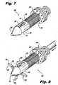
- Implant 100 is similar to the previously described implant 10 in that it includes an elongated threaded body portion 112, a tapered head portion 116 at the distal end of the body portion 112 and a proximal anchor portion 130 adapted for longitudinal movement along the length of the body portion 112 between a first portion spaced from the head portion 116 and a second position approximated with the head portion 116.
- Implant 100 differs from implant 10 in the manner in which the distal end portion thereof engages the adjacent anatomy (spinous processes 381a, 381b).
- the head portion 116 instead of having a plurality of outwardly biased pleats (20) as a distal anchor portion, the head portion 116 includes a plurality of circumferentially spaced apart deployable blades 120 that are mounted for pivotal movement about a pivot ring 123, within a bore 150 of the implant 100.
- the blades 120 are mounted for movement between a first, stowed position shown in Figure 7 , retracted within the head portion 116 and a second, deployed position shown in Figure 8 , projecting radially outwardly from the head portion 116.
- the body 112 of the implant 110 is provided with apertures 115, corresponding to each blade 120 provided.
- Movement of the blades 120 between the retracted and deployed positions is accomplished, at least in-part, through actuation by an internal plunger 126. More particularly, the surfaces of the head 128 of the plunger 126 act as a cam, and cooperate with inner cam surfaces 140 formed on each of the blades 120. As the plunger head 128 moves distally, cam surfaces 140 of the blades 120 follow the outer surface of the plunger head 128, and urge the blades 120 radially outwardly.
- orthogonal blades 120 are provided, although it is to be understood that any practicable number thereof can be provided, including but not limited to a total of one, two, three, four, five, six, seven, eight, nine or ten blades 120, for example.
- the blades 120 and their annular pivot ring 123 are mutually connected within the bore 150 of the body 112, thus forming a subassembly 119.
- the subassembly 119 can be provided in an axially fixed location along the longitudinal axis of the implant 100, or alternatively can be configured to permit limited axial movement of the subassembly 119.
- the blades 120 are fitted to the pivot ring 123, which is in-turn, positionally constrained to, or alternatively integrally formed with, the inner wall 152 of the bore 150. Securement of the axial position of the pivot ring 123 to the wall 152 can be facilitated in any suitable fashion, which may depend on the precise material selection. Mechanical connections can be utilized, for permitting snap or press fitting thereof, for example. For example, one or more stops in the form of protrusions, or alternatively grooves 154, can be provided in the bore 150. With such features, the pivot ring 123 can be captured and its axial position fixed. In this regard, the pivot ring 123 can be configured as a "split ring" or as an otherwise circumferentially compressible member.
- the subassembly 119 can be inserted axially from the proximal end 117 of the body 112, through the bore 150, and moved toward the distal end of the implant 100.
- Such engagement can be either permanent or temporary, depending on the precise implementation thereof.
- the ring 123 can be permanently attached, such as by welding, to the inner wall 152 of the bore 150, provided that compatible materials are used.
- the relative size and configuration of protrusions and/or grooves can be such that the pivot ring 123 is releasably captured by such features ( e.g. , groove 154), and can be removed therefrom upon application of sufficient force.
- the pivot ring 123 includes inherent mechanical properties including elasticity or stiffness ( i . e ., spring rate), frictional properties and the like, which depend on the material being used. If dimensioned and implemented suitably, the subassembly 119, including the blades 120 and the pivot ring 123 can be axially positioned at any stage by way of such a feature.
- the blades 120 can be stowed prior to placement of the implant 100.
- a stowed configuration of the subassembly 119 can permit the radially outer ends 132 thereof to be rotated inward, through the apertures 115, and into the bore 150 of the implant 100.
- the subassembly 119 can then be moved proximally, bringing the blades 120 fully within the bore 150, and capturing their radially outer ends 132 within the bore 150.
- a positioning feature such as a groove ( e.g ., 154) for example, can correspond with this stowed position and maintain the axial position of the subassembly 119 until deployment of the blades 120 is desired.
- the plunger 126 can be urged distally, pushing the subassembly 119 to an axial position in which the blades 120 are free to rotate about the pivot ring 123 and through the apertures 115, which can be accomplished by way of movement of the plunger 126 in connection with the cam surfaces 140 of the blades 120, as described above.
- the subassembly 119 can be configured to travel axially to the distal end of the bore 150, at which position the outer surfaces of the blades 120 abut the inner end face 152 of the bore 150. Such positioning advantageously inhibits eversion or overextension of the blades 120 from a deployed position in which they are configured to engage the target spinous processes 381a, 381b ( e.g ., Figs. 10-13 ).
- the head 128 of the plunger 126 can be figured with an outer diameter that is greater than an inner diameter of the pivot ring 123, so that actuation of the plunger 126 yields distal axial translation of the subassembly 119, simply by pushing against it, following rotation of the blades 120 outward, radially.
- one or more linear pivots can be provided in lieu of the pivot ring 123.
- Such linear pivots can be provided as stationary elements, secured to or through the body 112, or alternatively can be mounted for axial movement with respect to the body 112.
- Such linear pivots can be mounted tangentially or transversely, with respect to the body 112, or can be centrally mounted (e.g., transverse to and intersecting the longitudinal axis of the body 112).
- the plunger 126 itself can be provided with various features, including features to permit actuation thereof, and secure positioning thereof.
- the plunger 126 in addition to the distal rounded head 128, can include a proximal head 125 having a proximal internal recess 121, and an angled distal surface to facilitate distal-directed urging and proximal-directed urging, respectively, applied from the proximal direction.
- the plunger 126 can also include a recess 129, for securely engaging a resilient catch 127.
- the catch 127 is configured to interface between the plunger 126 and internal surface features of the body 112, such as annular grooves or recesses.
- the resilient catch 127 permits axial movement of the plunger 126, and in conjunction with the above-described internal surface features of the body 112, defined positions at which the plunger 126 is held, inhibiting unintentional movement therefrom.
- the catch 127 can be formed of any suitable material or configuration, such as from a resilient material, such as an elastomer, or as a resilient structure, such as a toroidal metallic coil, or a combination of these, for example.
- the plunger 126 is overmolded with an elastomeric material.
- a more discrete element is provided, which configuration can equally be applied to this embodiment.
- the implant 100 is also similar to implant 10 in that the distal surface of the proximal anchor 130 can include a plurality of distally facing spikes 134 for engaging one side of the spinous processes 381a, 381b adjacent to the target interspinous process space 382 ( Figs. 10-13 ).
- the proximal facing surfaces of the blades 120 is furnished with spikes 124 for engaging the other side of the spinous processes 381a, 381b.
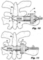
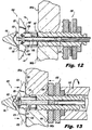
- Figures 10-13 illustrate various stages during insertion and placement of the implant 100.
- Figure 10 is a dorsal (rear) view of the implant 100 illustrating the implant during installation into a target interspinous process space 382.
- Figure 11 is a dorsal view of the implant 100, illustrating the implant 100 during installation, advanced to a position where distal anchor elements or blades 120 are unobstructed by anatomy, allowing for deployment thereof.
- Figure 12 is a dorsal view of the implant 100, illustrating the implant 100 during installation, with the distal anchor elements 120 in a deployed condition.
- Figure 13 is a dorsal view of the implant 100, illustrating the implant 100 with the proximal anchor 130 urged distally, causing engagement of the implant 100 with the adjacent spinous processes 381a, 381b.
- the implant 100 can be inserted into a target interspinous process space 382 with the blades 120 already deployed, extending outwardly from the body 112.
- the plunger 126 is placed in a distal position where the blades 120 are deployed.
- the plunger 126 can be placed in a partly extended (intermediate) position, or in a fully extended position. In a partly extended position, radially-inward urging of the blades 120 causes proximal urging of the plunger 126.
- the plunger 126 therefore, can be provided with a stop or as spring-biased to a distal or intermediate position.
- the implant 100 can be embodied such that the pivot ring 123, or other pivot arrangement, permits inward urging of the blades 120 despite placement of the plunger 126 in its fully extended position. In such an arrangement, the blades 120 pivot about the head 128 of the plunger 126, as the pivot ring 123 flexes to permit the ends 132 of the blades 120 to move inwardly.
- FIGs 14-24 illustrate an interspinous process implant 200 in accordance with a further embodiment of the invention.
- the implant 200 includes certain features of the foregoing embodiments, where similar elements are designated with similar reference numbers as used above.
- the implant 200 includes a body 212, providing overall structure to the implant 200.
- the body 212 as illustrated, is provided with threads 222 for facilitating insertion of the implant 200 into a target interspinous process space 382 ( Figs. 20-24 ), as will be described in more detail below in connection with Figures 20-24 , as well as for providing additional engagement with the anatomy of the patient in the target interspinous process space 382.
- threads 222 permit rotational engagement between the body 212 and a proximal nut 235, provided to securely engage the implant 200 with interspinous processes 381a, 381b adjacent the target interspinous process space 382, which will be described in more detail below.
- this implant 200, and the other implants 10, 100 of the invention can be provided without threads thereon, or with threads provided only on a portion thereof for one of the foregoing functions. That is, if desired, threads 222 can be provided only on the proximal end of the body 112, for engaging the nut 235 and not on the distal portion, or vice versa.
- a distal anchor portion is provided, and in this embodiment is configured as two opposed deployable blades 220 (220a, 220b).
- the blades 220 are provided with a common pivot, defined by a pin 259 passing therethrough, as well as through the body 212.
- Use of a common pivot advantageously minimizes the space required for housing all elements within the body 212 in their stowed state, although variations from this precise configuration are possible.
- two separate pivots can be provided for each blade 220a, 220b, still in keeping with the invention.
- the blades 220 are provided with proximally directed spikes 224 for engaging the relevant adjacent bony anatomy, such as the spinous processes 381a,381b. In embodiments not according to the invention blades 220 can alternatively be provided without such spikes 224.
- the blades 220a, 220b are respectively provided with hinge portions 223a, 223b for engaging the pin 259.
- one hinge portion 223a is shaped as a clevis, while the other 223b is shaped to fit within the clevis-shaped hinge portion 223a.
- a plunger 226 is provided and includes a head portion 228 shaped and configured to act as a cam and cooperate with inner cam surfaces 240 formed on each of the blades 220a, 220b, as described above.
- cam surfaces 240 of the blades 220a, 200b follow the outer surface of the plunger head 228, and urge the blades 220a, 220b radially outwardly.
- the plunger can include, as described above, a proximal head 225 having a proximal internal recess 221, and an angled distal surface to facilitate distally-directed urging and proximal-directed urging, respectively, applied from the proximal direction.
- the plunger 226 can also include a recess 229, for securely engaging a resilient catch 227.
- the catch 227 is configured to interface between the plunger 226 and internal surface features of the body 212, such as annular grooves or recesses 254.
- the resilient catch 227 permits axial movement of the plunger 226, and in conjunction with the above-described internal surface features of the body 212, defined positions at which the plunger 226 is held, inhibiting unintentional movement therefrom.
- the catch 227 can be formed of any suitable material or configuration, such as from a resilient material, such as an elastomer, or as a resilient structure, such as a toroidal metallic coil, or a combination of these, for example.
- the catch 227 can be, in accordance with the invention, a canted coil, such as a Bal LatchTM, available from Bal Seal Engineering, Inc. of Foothill Collins, California, USA.
- the blades 220 When deployed, the blades 220 function in concert with the proximal anchor portion 230, which is axially moveable along the length of the implant 200.
- the nut 235 includes threads on its inner surface that engage the threads 222 provided on the outer surface of the body 212. Accordingly, rotational movement of the nut 235 yields axial movement thereof. When that axial movement is in the distal direction, the nut 235 urges the proximal anchor portion 230 distally until it abuts the bony structures (e.g. spinous processes 381a, 381b) surrounding the target interspinous process space 382. If provided, protrusions or spikes 234 on the proximal anchor portion facilitate engagement with the bone and thus stabilization of the entire vertebrae-implant construct.
- the bony structures e.g. spinous processes 381a, 381b
- opposed flat portions 217 comprising upper and lower flat portions 217a, 217b, respectively, guide correspondingly shaped (e.g., flat) portions 237 of the proximal anchor 230, permitting axial movement but inhibiting rotational movement thereof, during movement of the nut 235.
- a lock washer 233 or equivalent feature can be provided to inhibit unintentional loosening of the nut 235 following implantation and deployment of the blades 220a, 220b.
- the blades 220 can be provided with an internal spring element 281, spanning between respective recess in each of the blades 220a, 220b.
- the spring element 281 can be provided straight to maintain the blades 220a, 220b deployed (open) normally, or alternatively, bent, to maintain the blades 220a, 220b stowed (contracted) normally.
- the spring element 281 is provided bent, and urges the blades 220a, 220b inwardly, toward the stowed position, prior to and during implantation.
- the spring 281 serves to maintain a position of the blades 220.
- a head portion 228 thereof engages a corresponding detent 249 in the profile 240 of the blades 220a, 220b.
- the engagement of the detent 249 by the head portion 228 further ensures secure deployment of the blades 220a, 220b.
- the spring element 281 can alternatively be provided as normally straight, urging the blades 220a, 220b outwardly toward the deployed position, prior to, during and following implantation. During implantation, however, the spring element 281 permits inward rotation of the blades 220a, 220b, temporarily bending the spring element 281 in the process. Thus, during implantation the spring 281 serves to maintain a position of the blades 220a, 220b against externally-applied forces. Once placed in the target interspinous process space 382, the plunger 226 can be urged distally in order to lock the blades 220a, 220b in the deployed position.
- the body 212 includes at its proximal end, an expanded-diameter portion 213, defining a proximal-most limit for traveling of the nut 235 and proximal anchor 230. Also in the proximal end portion, formed within the bore 250, is a shaped socket 251 for engagement with an insertion tool. As illustrated, the socket 251 is substantially hexagonal, with flat portions defined at regular angular intervals. Practicable departures from the precise configuration illustrated are possible. The shaped socket 251 facilitates mutual rotational engagement between the implant 200 and the insertion tool.
- transverse grooves 253 which, in conjunction with a corresponding element on the insertion tool, inhibit unintentional mutual axial displacement therebetween.
- the corresponding element on the insertion tool can be, for example, a resiliently and optionally lockable protrusion extending laterally ( i . e ., radially) from the insertion tool.
- the lockable protrusion may be, for example, a lockable spring-loaded spherical element, for example.
- the implant 200 can be provided with one or more apertures 214 to permit packing of the implant, such as in the bore 250 thereof, with osteogenesis-promoting substances to facilitate bone ingrowth and/or fusion, such as demineralized bone.
- Figures 20-24 illustrate various stages during insertion and placement of the implant 200 into a target interspinous process space 382.
- Figure 20 is a perspective view of the implant 200, in preparation to be installed dorsally through a curved introducer tube 387, which has been inserted through an incision 389 formed through the skin 388 of a patient.
- Figure 21 is a dorsal (rear) view of the implant 200, held by an elongate insertion tool 392, within a lumen of an introducer tube 397, during lateral insertion thereof.
- Figure 22 is a dorsal view illustrating the implant 200, laterally advancing to the target interspinous process space 382, under application of a rotational force applied by the insertion tool 392, by virtue of the threads 222 provided on the body 212 thereof.
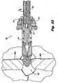
- Figure 23 is a dorsal view illustrating the implant 200 with the internal plunger 226 urged distally, effecting deployment of the distal anchor elements- in this case, blades 220a, 220b.
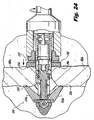
- FIG. 24 is a dorsal view illustrating the implant 200 with the proximal anchor element 230 urged distally by the nut 235, engaging the adjacent spinous processes 281 a, 281b.
- a sleeve 387 is provided to facilitate insertion.
- the insertion methods can include use of a stylet, dilators, and the like to gain access and define a path for the sleeve 387, as will be described in more detail below.
- dorsal insertion can be accomplished as set forth in U.S. Patent Application Serial No. 12/011,905, filed January 30, 2008 ( U.S. Pub. No. 2009/0054988 ).
- dorsal insertion of the subject implants can be effected by forming an incision 389 through the skin 388 of a patient, at a level corresponding to a target interspinous process space 382, defined between adjacent vertebral processes 381a, 381b.
- the path traversed by the implant 200, and therefore also by the sleeve 387 is curved to align the path and the implant 200 with the target interspinous process space 382.
- Figure 21 in contrast, illustrates direct lateral insertion of the implant 200 into the target interspinous process space 382.
- an incision 399 is formed in the skin 388 of a patient, and ultimately a sleeve 397 is advanced through the tissue to the target interspinous process space 382, through which the implant 200 is advanced, connected to the insertion device 392.
- the implant 200 is axially rotated by way of the insertion device 392, thus threading the implant 200 into the target interspinous process space 382, distracting the adjacent spinous processes 381a, 381b, and advancing the implant 200 into its final position, generally centered with respect to the spinous processes 381a, 381b.
- distraction can be performed in advance by a separate instrument, with insertion of the implant following, and maintaining such distraction.
- relative rotation and axial translation between the implant 200 and the insertion device 392 is preferably inhibited by the above-mentioned features.
- the anchoring blades 220a, 220b When in position, the anchoring blades 220a, 220b can be deployed, as shown in Figure 23 . Subsequently, the nut 235 can be tightened, advancing the locking proximal anchor 230 distally into engagement with the spinous processes 381a, 381b.
- one or more osteogenesis promoting substances can be packed in and/or around the implant 200 to promote bone ingrowth and/or spinal fusion, if desired.
- a separate tap can be used in the target interspinous process space 382 before the insertion of the implant 200, or as mentioned above, the implant 200 can be provided with features that provide self-tapping capability.
- Methods of lateral insertion of the spinal implant 200 into a target interspinous process space 382 can include, following forming the incision 399, inserting a stylet (not illustrated) through the incision 399, laterally to the target interspinous process space 382, preferably using an internal imaging technique, such as fluoroscopy.
- Insertion of the stylet forms an entry path, along which one or more dilators can be sequentially advanced; in order to dilate soft tissues between the incision and the target interspinous process space 382.
- the sleeve 397 can then be advanced through the entry path.
- a distractor which can be a tap ( e . g ., a graduated tap)
- a distractor can then be inserted and advanced into the target interspinous process space 382, to tap and gradually distract the adjacent spinous processes 381a,381b and/or help determine an appropriate size of implant to be inserted.
- the implant 200 can be inserted, held by the insertion device 392, advanced through the sleeve 397, up to the target interspinous process space 382, after which the implant 200 can be inserted into the target interspinous process space 382.
- rotational motion is applied to advance the implant 200 and, if not already distracted, to distract the adjacent spinous processes 381a, 381b.
- laterally-directed pressure can be applied until the implant 300 is in the desired position, after which any proximal and/or distal engagement elements can be deployed.
- Many of the primary structural components of the implant devices described herein are preferably formed from biological and/or biocompatible materials, including metal, ceramic, polymeric and/or composite materials that can be selected to have a modulus of elasticity that is substantially similar to that of bone, for example, polyetheretherketone thermoplastic (PEEK), machined bone, a titanium alloy or stainless steel, for example.
- PEEK polyetheretherketone thermoplastic
Description
- The subject invention is directed to spinal implants, and more particularly, to an interspinous process implant for spinal stabilization, for percutaneous placement in a target interspinous process space, which can also serve as a fusion cage spacer to treat lumbar spinal stenosis.
- The spine consists of a column of twenty-four vertebrae that extend from the skull to the hips. Discs of soft tissue are disposed between adjacent vertebrae. The vertebrae provide support for the head and body, while the discs act as cushions. In addition, the spine encloses and protects the spinal cord, defining a bony channel around the spinal cord, called the spinal canal. There is normally a space between the spinal cord and the borders of the spinal canal so that the spinal cord and the nerves associated therewith are not pinched.
- Over time, the ligaments and bone that surround the spinal canal can thicken and harden, resulting in a narrowing of the spinal canal and compression of the spinal cord or nerve roots. This condition is called spinal stenosis, which results in pain and numbness in the back and legs, weakness and/or a loss of balance. These symptoms often increase after walking or standing for a period of time.
- There are number of non-surgical treatments for spinal stenosis. These include non-steroidal anti-inflammatory drugs to reduce the swelling and pain, and corticosteroid injections to reduce swelling and treat acute pain. While some patients may experience relief from symptoms of spinal stenosis with such treatments, many do not, and thus turn to surgical treatment. The most common surgical procedure for treating spinal stenosis is decompressive laminectomy, which involves removal of parts of the vertebrae. The goal of the procedure is to relieve pressure on the spinal cord and nerves by increasing the area of the spinal canal.
- Interspinous process decompression (IPD) is a less invasive surgical procedure for treating spinal stenosis. With IPD surgery, there is no removal of bone or soft tissue. Instead, an implant or spacer device is positioned behind the spinal cord or nerves between the interspinous processes that protrude from the vertebrae in the lower back. A well-known implant used for performing IPD surgery is the X-STOP® device, which is described in
U.S. Patent No. 6,419,676 . However implantation of the X-STOP® device still requires an incision to access the spinal column to deploy the X-STOP® device. - An interspinous process implant placed in a minimally invasive surgical procedure is disclosed in
U.S. Patent Application Publication 2008/0243250 . This implant functions as a spacer between two adjacent spinous processes, but it is not designed to stabilize the spinous process and can migrate over time. -
US 2006/264938 A1 discloses a spinal implant according to preamble part of claim 1. - Further relevant prior art is known from
US 2007/032790 A1 ,WO 2008/088613 A2 andUS 2008/281359 A1 . - It would be advantageous to provide an implant for performing IPD procedures that can be percutaneously inserted into the interspinous process space to effectively treat lumbar spinal stenosis by distracting, or maintaining distraction, and sufficiently stabilizing adjacent spinous processes, and thus, adjacent vertebrae.
- The object is solved by the features of claim 1. The dependent claims contain further preferred developments of the invention.
- The invention is directed to a spinal implant having an elongated body dimensioned and configured to function as a spacer, for placement in a target interspinous process space, between two adjacent spinous processes, a distal anchor associated with a distal end of the body, and a proximal anchor mounted for longitudinal movement along the body between a first position spaced apart from the distal anchor and a second position approximated with the distal anchor, adapted to compress the two adjacent spinous processes, in conjunction with the distal anchor.
- The proximal anchor can include an axially slideable plate.
- The elongated body can be provided with threads at least on a distal portion thereof for facilitating engagement with bony anatomical structures.
- The proximal anchor can include a plurality of circumferentially spaced apart distally facing spikes for engaging the spinous processes when the distal anchor and the proximal anchor are approximated.
- The body and proximal anchor can be threadedly associated with one another to facilitate longitudinal movement of the proximal anchor along the body between the first and second positions.
- The body can be at least partially hollow and include a plurality of openings for permitting tissue ingrowth.
- The distal anchor is provided with a tapered head portion, which can be configured to gradually distract the two adjacent spinous processes during insertion therebetween. Similarly, the shape of the body can ease insertion of the implant in-between the adjacent spinous processes after distraction thereof by a separate instrument or instruments.
- The distal anchor can include a plurality of radially-deployable blades adapted for engaging adjacent spinous processes. The body can be provided with an internal chamber in which the plurality of radially-deployable blades are stowed prior to deployment thereof. The plurality of radially-deployable blades can be hinged by a common annular pivot member. Alternatively, the plurality of radially-deployable blades can be hinged by a common linear pivot member. The spinal implant can further include an internal plunger adapted for deploying the plurality of radially-deployable blades, by way of a camming mechanism.
- In accordance with the invention, the distal anchor can be provided in either a normally expanded or otherwise deployed condition, or alternatively, in a normally contracted or otherwise stowed condition. The term "normally" means that the implant, absent externally-applied forces, maintains that condition.
- The distal anchor includes a tapered head, wherein the tapered head has a maximum diameter that is, in its neutral state, greater than a diameter of the elongated body. The tapered head has a plurality of circumferentially spaced apart proximally-facing spikes for engaging the spinous processes when the distal anchor and the proximal anchor are mutually approximated. The tapered head can have a trailing skirt section adapted and configured for movement between a radially expanded condition and a radially compressed condition as the head is inserted between the two adjacent spinous processes. The trailing skirt section of the head can include a plurality of circumferentially spaced apart hinged pleats that are biased into the radially expanded condition. Alternatively, these pleats can be biased in a radially contracted condition. The pleats can be biased by spring elements.
- In an ambodiment, the spinal implant has an elongated body dimensioned and configured to function as a spacer, for placement in a target interspinous process space, between two adjacent spinous processes, the body having a tapered head portion, configured to gradually distract the two adjacent spinous processes during insertion therebetween, a distal anchor associated with a distal end of the body, the distal anchor having a plurality of deployable blades adapted to engage a first side of the two adjacent spinous processes, and a proximal anchor mounted for longitudinal movement along the body between a first position spaced apart from the distal anchor and a second position approximated with the distal anchor, adapted to engage a second side of the two adjacent spinous processes. Alternatively, the body can maintain distraction performed by another instrument, prior to insertion of the implant.
- Also disclosed is a method of percutaneously performing interspinous process decompression, comprising the steps of providing a spinal implant having an elongated body dimensioned and configured to function as a spacer, for placement in a target interspinous process space, between two adjacent spinous processes, a distal anchor associated with a distal end of the body, and a proximal anchor mounted for longitudinal movement along the body between a first position spaced apart from the distal anchor and a second position approximated with the distal anchor, adapted to compress the two adjacent spinous processes, in conjunction with the distal anchor, forming an incision in a patient's skin, lateral from a target interspinous process space, in which the implant is to be placed, inserting a stylet through the incision, laterally to the target interspinous process space, using an internal imaging technique, to form an entry path, inserting one or more dilators, sequentially, along the entry path to dilate soft tissues between the incision and the target interspinous process space, inserting a sleeve through the entry path, selecting an implant having a size appropriate for a desired amount of interspinous distraction, inserting the implant, held by an insertion device, through the sleeve, up to the target interspinous process space, and advancing the implant into the interspinous process space.
- In accordance with the method, after the step of inserting the sleeve, a tap can be used. The tap can be a graduated-type tap, the diameter of which increasing toward the proximal end thereof. During rotation of such a tap, threads are cut into the adjacent spinous processes. If the tap is graduated, the adjacent spinous processes are gradually mutually distracted during advancement of the tap. Further, based on the distance the tap advances through the target interspinous process space, the surgeon can determine the size of the implant to insert. In such an arrangement, the subject implant maintains distraction performed by the tap, and does not necessarily perform distraction.
- The advancing step can include rotating the implant along a longitudinal axis thereof, to effect axial advancement of the implant by way of threads formed on an outer surface thereof.
- So that those skilled in the art to which the subject invention relates will readily understand how to make and use the interspinous process implant of the subject invention without undue experimentation, embodiments thereof will be described in detail herein below with reference to certain figures, wherein:
-
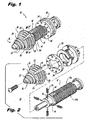
Figure 1 is a perspective view of an interspinous process implant in accordance with a first exemplary embodiment of the invention; -
Figure 2 is an exploded view of the implant ofFigure 1 , illustrating the components thereof; -
Figure 3 is a dorsal (rear) view of the implant ofFigures 1-2 , illustrating the implant during installation into a target interspinous process space, prior to compression of a distal end portion thereof; -
Figure 4 is a dorsal view of the implant ofFigures 1-2 , illustrating the implant during installation into a target interspinous process space, during compression of the distal end portion thereof; -
Figure 5 is a dorsal view of the implant ofFigures 1-2 , illustrating the implant in final position in the target interspinous process space, with a proximal anchor urged distally engaging a proximal surface of adjacent spinous processes, and the proximal end portion engaging distal surface of the adjacent spinous processes; -
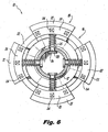
Figure 6 is a cross-sectional view of the implant ofFigure 1 , taken along line 6-6 ofFigure 1 , illustrating details of the distal end portion thereof; -
Figure 7 is a perspective view of an interspinous process implant in accordance with a second exemplary embodiment of the invention, showing distal anchor elements in a stowed position; -
Figure 8 is a perspective view of the implant ofFigure 7 , showing the distal anchor elements in a deployed condition; -
Figure 9 is an exploded view of the implant ofFigures 7-8 , illustrating the components thereof; -
Figure 10 is a dorsal (rear) view of the implant ofFigures 7-9 , illustrating the implant during installation into a target interspinous process space; -
Figure 11 is a dorsal view of the implant ofFigures 7-9 , illustrating the implant during installation, advanced to a position where distal anchor elements are unobstructed by anatomy, to allow for deployment thereof; -
Figure 12 is a dorsal view of the implant ofFigures 7-9 , illustrating the implant during installation, with the distal anchor elements in a deployed condition; -
Figure 13 is a dorsal view of the implant ofFigures 7-9 , illustrating the implant with a proximal anchor element urged distally, causing engagement of the implant with the adjacent spinous processes; -
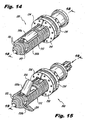
Figure 14 is a perspective view of an interspinous process implant in accordance with a third exemplary embodiment of the invention, illustrating distal anchor elements in a stowed position; -
Figure 15 is a perspective view of the implant ofFigure 14 , illustrating the distal anchor elements in a deployed condition; -
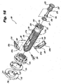
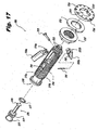
Figure 16 is a rear exploded view of the implant ofFigures 14-15 ; -
Figure 17 is a front exploded view of the implant ofFigures 14-15 ; -
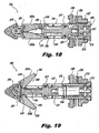
Figure 18 is a cross-sectional view of the implant ofFigures 14-15 taken at line 18-18 ofFigure 14 , where the distal anchor elements are in a stowed position; -
Figure 19 is a cross-sectional view of the implant ofFigures 14-15 taken at line 19-19 ofFigure 15 , where the distal anchor elements are in a deployed position; -
Figure 20 is a perspective view, illustrating an implant in preparation to be installed dorsally, illustrated with the implant ofFigures 14-15 but applicable to all embodiments of the invention; -
Figure 21 is a dorsal view of an implant within an introducer tube during lateral insertion thereof, illustrated with the implant ofFigures 14-15 but applicable to all embodiments of the invention; -
Figure 22 is a dorsal view illustrating the implant ofFigures 14-15 , showing the implant being screwed into a target interspinous process space; -
Figure 23 is a dorsal view illustrating the implant ofFigures 14-15 , showing the implant with internal plunger urged distally, effecting deployment of the distal anchor elements; and -
Figure 24 is a dorsal view illustrating the implant ofFigures 14-15 , showing the proximal anchor element urged distally, engaging the adjacent spinous processes. - With reference to
Figures 1-6 , there is illustrated an interspinous implant constructed in accordance with a preferred embodiment of the subject invention and designated generally byreference numeral 10. Theimplant 10 is particularly well adapted for use in performing minimally invasive surgical procedures for treating spinal stenosis, including, for example, interspinous process decompression (IPD). - It is envisioned however, that the
implant 10 of the subject invention can be used in other spinal procedures as well, including, but not limited to as an adjunct to spinal fusion procedures, or as a spinal stabilization device. Those skilled in the art will readily appreciate from the following description that the interspinous process implant of the subject invention is well adapted for percutaneous insertion, and thus overcomes many of the drawbacks of prior art devices presently used in IPD procedures. That is, theimplant 10 is dimensioned and configured for introduction and placement through a small skin incision rather than in an open surgical procedure involving a cut down of tissue, as will be described in more detail hereinbelow. - The
interspinous process implant 10 includes an elongated threadedbody portion 12 which can be configured as a solid element or alternatively can be at least partially hollow, and which may include a plurality oflongitudinal openings 14 to permit insertion of demineralized bone or another type of osteogenesis-promoting substances or fusion adjunct material, and also promote the ingrowth of bone. Theimplant 10 further includes a tapered orconical head portion 16, which is associated with a distal end of thebody portion 12. Thehead portion 16 can be dimensioned and configured to progressively distract two adjacentspinous processes implant 10 is advanced therebetween. It is to be understood, however, that thehead portion 16 facilitates insertion of the implant, when distraction is initially performed by a separate instrument. It is also to be understood that theelongated body portion 12 can alternatively be provided without threads, in accordance with an alternative aspect of the invention. - The
head portion 16, and with other embodiment set forth herein, tapers axially inwardly, by an angle between about 5 degrees and about 65 degrees, with respect to a longitudinal axis of theimplant 10. In accordance with one aspect of the invention, this angle is between about 15 and about 45 degrees. In accordance with another aspect of the invention, this angle is between about 25 and about 35 degrees. In accordance with still another aspect of the invention, this angle is about 30 degrees. It is to be understood however, that this angle is not limited to the foregoing ranges. - The
head portion 16 can be attached to the body portion in any suitable manner, including mechanical fasteners, mechanical interlock, welding or the like. In the illustrated embodiment, an axial screw element is provided, although an internal threaded connection can be provided, for example. - The tapered
head 16 ofimplant 10 is included in a distal anchor portion configured with a trailingskirt section 18. Theskirt section 18, as embodied, is a dynamic structure formed from a plurality of circumferentially spaced apart pleats 20. Thepleats 20 can be hinged, and generally arcuate in configuration. Hinging can be accomplished by way of a defined line of weakness in the material, so as to form a "living hinge," or alternatively can be a conventional hinge with a separate pivot. Alternatively still, the necessary deflection of thepleats 20 can be accomplished without a defined hinge, utilizing only the cumulative bending of thepleats 20 along their length. Further, thepleats 20 can be embodied in shapes other than those having an arcuate configuration, such as a generally rectangular parallelepiped, for example. - In accordance with one preferred aspect, the
head portion 16 and trailingskirt section 18 havehelical threads 22 so as to ease progressive advancement of thehead portion 16 andskirt section 18 between the two adjacent bonyspinous processes threads 22 serve to draw theimplant 10 into the targetinterspinous process space 382, defined by the adjacentspinous processes helical threads 22 can be any of a variety of suitable forms, such as, for example, cutting threads or box threads. However, it is also envisioned and well within the scope of the subject disclosure that the taperedhead portion 16 andskirt section 18 can be provided without any threads. Further, an integral tap chamfer can be incorporated into the threads, if so-desired. In embodiments in which no threads are provided, thehead portion 16 of theimplant 10 can be advanced between the two adjacentspinous processes - As best seen in
Figure 6 , each of thearcuate pleats 20 of theskirt section 18 are biased into a radially expanded condition shown inFigure 1 by coiled biasing springs 25. The coiled biasing springs 25 are supported on guide pins 26 that are retained inbody portion 12 byheads 28. Theheads 28 of the guide pins 26 act to limit the extent to which thearcuate pleats 20 ofskirt section 18 can extend. It is envisioned that alternative biasing mechanisms can be used to bias thepleats 20 into an expanded condition, including but not limited to a provision of elastic material, such as an elastomer. Such a material can be a bio-compatible silicone, for example. As explained in more detail below, thepleats 20 are adapted and configured for movement between a (first) radially expanded condition shown inFigures 1-3 and5 and a (second) radially compressed condition shown, for example, inFigure 4 . If desired, a sheath (not illustrated) can be provided over the structure of thehead portion 16, such as a thin layer of a biocompatible elastomer, to maintain a continuous surface while permitting flexibility between the pleats. Alternatively, webs or similar elements can be provided betweenadjacent pleats 20. - The
implant device 10 further includes aproximal anchor portion 30 that is operatively associated with the threadedbody 12 in such a manner so as to enable the longitudinal movement of theanchor portion 30 along the length ofbody 12 between a first position, spaced from the head portion 16 (e.g.,Figure 3 ) and second position, approximated with the head portion 16 (e.g.,Figure 5 ). It is envisioned that the operative connection between thebody portion 12 and theproximal anchor 30 can be accomplished in a variety of ways including a direct threaded engagement between theproximal anchor 30 and thebody 12 or through the use of a captured threaded nut that permits theproximal anchor 30 to translate longitudinally along the threadedbody portion 12 without rotating about the axis of thebody portion 12, such as by providing one or more interfacing flat regions 17a, 17b. - With reference to
Figures 1-6 , the proximal surfaces of thearcuate pleats 20 of the trailingskirt section 18 are provided with proximally-directedspikes 24 adapted and configured to engage the bony anatomy of thespinous processes head portion 16 and theanchor portion 30 are mutually approximated about thespinous processes proximal anchor 30 can include a plurality of circumferentially spaced, distally facingspikes 34 for engaging the bonyspinous processes head portion 16 and theanchor portion 30 are mutually approximated into the position shown inFigure 5 . Thespikes 34, or any spikes described herein in connection with any embodiment of the invention are not limited to any particular shape, but can be generally conical, pyramidal or tetrahedral, for example. Alternatively, the spikes can be truncated versions of such shapes. - In use, as the
head portion 16 is inserted between the two adjacentspinous processes Figure 4 , thepleats 20 of theskirt section 18 are urged into a compressed condition, against the bias of the coiled springs 25, or alternative biasing elements. In accordance with the invention, thepleats 20 can compress so as to not extend beyond the diameter of thebody 12, if necessary. Once theskirt section 18 is beyond the distractedspinous processes pleats 20 are urged back into their normally expanded position under the bias of the springs'25. Theimplant 10, alternatively, can be inserted following insertion of a separate instrument, such as a tap or other distractor, in which case theimplant 10 does not necessarily cause distraction during insertion thereof, but rather maintains distraction. - In accordance with a method, the
head portion 16 can be provided and inserted in a collapsed state, and expanded when theimplant 10 is placed in the desired position. Expansion of thehead portion 16 can be achieved by way of an internal cam mechanism, as described in connection with the embodiments described below. In such an arrangement, an outwardly biasing member can be eliminated, while theheads 28 of the guide pins 26 follow an internal moveable cam, for example. It may be desirable in such an arrangement to provide inwardly-biasing elements (e.g., springs placed within thebody 12, between thebody 12 and the pin heads 28, if the structure of thehead portion 16 alone is not sufficient to maintain a collapsed condition of thehead portion 16. The reader will appreciate that any implant constructed in accordance with the invention can be provided in a normally deployed condition, or a normally collapsed condition. - Thereafter, the
proximal anchor 30 is moved into approximation with thehead portion 16, as shown inFigure 5 . Once approximated, thehead portion 16, having a distal anchor composed of thepleats 20, and theproximal anchor 30 compress thespinous processes spikes implant 10 against unintentional migration. The resulting construct serves to stabilizespinous processes interspinous process space 382, while at the same time thebody portion 12 acts as a spacer between thespinous processes - The
body 12, as with any of the other embodiments described herein can be provided with the following dimensions, but are not limited thereto. Thebody portion 12 is dimensioned and configured for threaded placement between the spinous processes of symptomatic disc levels. In this regard, it is envisioned that the outer diameter of theimplant 10 can range from about 8.0 mm to about 16.0 mm, with the thread depth being about 1.0 mm. The threads on thebody portion 12 of theimplant 10 can be configured so that the implant is self-tapping to ease insertion of the implant into the interspinous process space, as described below. As mentioned, theimplant 10, as with any implant in accordance with the invention, can be provided with or without threads, as desired or required. - The components of the
implant 10, or any implant constructed in accordance with the invention can be formed out of similar or identical materials to one another. For example, polymeric materials, such as PEEK, alloys, such as titanium alloys or shape-memory alloys, such as Nitinol, ceramic and/or composite materials can be used, as desired or required. However, it is specifically envisioned that the components of theimplant 10 can be formed from different materials from one another. For example, thebody 12 can be formed from a polymeric material, such as PEEK, while the head portion can be formed of an alloy, such as a titanium alloy or a shape-memory alloy, such as Nitinol. Ceramic and/or composite materials can additionally or alternatively be used, as desired or required. - Referring now to
Figures 7-13 , there is illustrated another embodiment of the implant of the subject invention, which is designated generally byreference numeral 100.Implant 100 is similar to the previously describedimplant 10 in that it includes an elongated threadedbody portion 112, atapered head portion 116 at the distal end of thebody portion 112 and aproximal anchor portion 130 adapted for longitudinal movement along the length of thebody portion 112 between a first portion spaced from thehead portion 116 and a second position approximated with thehead portion 116. -
Implant 100 differs fromimplant 10 in the manner in which the distal end portion thereof engages the adjacent anatomy (spinous processes head portion 116 includes a plurality of circumferentially spaced apartdeployable blades 120 that are mounted for pivotal movement about apivot ring 123, within abore 150 of theimplant 100. In particular, theblades 120 are mounted for movement between a first, stowed position shown inFigure 7 , retracted within thehead portion 116 and a second, deployed position shown inFigure 8 , projecting radially outwardly from thehead portion 116. Thebody 112 of the implant 110 is provided withapertures 115, corresponding to eachblade 120 provided. - Movement of the
blades 120 between the retracted and deployed positions is accomplished, at least in-part, through actuation by aninternal plunger 126. More particularly, the surfaces of thehead 128 of theplunger 126 act as a cam, and cooperate with inner cam surfaces 140 formed on each of theblades 120. As theplunger head 128 moves distally, cam surfaces 140 of theblades 120 follow the outer surface of theplunger head 128, and urge theblades 120 radially outwardly. - As illustrated, four
orthogonal blades 120 are provided, although it is to be understood that any practicable number thereof can be provided, including but not limited to a total of one, two, three, four, five, six, seven, eight, nine or tenblades 120, for example. - The
blades 120 and theirannular pivot ring 123 are mutually connected within thebore 150 of thebody 112, thus forming a subassembly 119. The subassembly 119 can be provided in an axially fixed location along the longitudinal axis of theimplant 100, or alternatively can be configured to permit limited axial movement of the subassembly 119. - In one aspect, the
blades 120 are fitted to thepivot ring 123, which is in-turn, positionally constrained to, or alternatively integrally formed with, the inner wall 152 of thebore 150. Securement of the axial position of thepivot ring 123 to the wall 152 can be facilitated in any suitable fashion, which may depend on the precise material selection. Mechanical connections can be utilized, for permitting snap or press fitting thereof, for example. For example, one or more stops in the form of protrusions, or alternatively grooves 154, can be provided in thebore 150. With such features, thepivot ring 123 can be captured and its axial position fixed. In this regard, thepivot ring 123 can be configured as a "split ring" or as an otherwise circumferentially compressible member. As such, the subassembly 119 can be inserted axially from the proximal end 117 of thebody 112, through thebore 150, and moved toward the distal end of theimplant 100. Such engagement can be either permanent or temporary, depending on the precise implementation thereof. Alternatively or additionally, to achieve permanent positioning, thering 123 can be permanently attached, such as by welding, to the inner wall 152 of thebore 150, provided that compatible materials are used. - If repositionability of the subassembly 119 is desired, the relative size and configuration of protrusions and/or grooves can be such that the
pivot ring 123 is releasably captured by such features (e.g., groove 154), and can be removed therefrom upon application of sufficient force. In this regard, thepivot ring 123 includes inherent mechanical properties including elasticity or stiffness (i.e., spring rate), frictional properties and the like, which depend on the material being used. If dimensioned and implemented suitably, the subassembly 119, including theblades 120 and thepivot ring 123 can be axially positioned at any stage by way of such a feature. - As shown in
Figure 7 , theblades 120 can be stowed prior to placement of theimplant 100. To inhibit unintended pivoting of theblades 120 about thepivot ring 123, which could interfere with the insertion process, a stowed configuration of the subassembly 119 can permit the radially outer ends 132 thereof to be rotated inward, through theapertures 115, and into thebore 150 of theimplant 100. The subassembly 119 can then be moved proximally, bringing theblades 120 fully within thebore 150, and capturing their radially outer ends 132 within thebore 150. A positioning feature, such as a groove (e.g., 154) for example, can correspond with this stowed position and maintain the axial position of the subassembly 119 until deployment of theblades 120 is desired. At that time, theplunger 126 can be urged distally, pushing the subassembly 119 to an axial position in which theblades 120 are free to rotate about thepivot ring 123 and through theapertures 115, which can be accomplished by way of movement of theplunger 126 in connection with the cam surfaces 140 of theblades 120, as described above. - Optionally, the subassembly 119 can be configured to travel axially to the distal end of the
bore 150, at which position the outer surfaces of theblades 120 abut the inner end face 152 of thebore 150. Such positioning advantageously inhibits eversion or overextension of theblades 120 from a deployed position in which they are configured to engage thetarget spinous processes Figs. 10-13 ). - In configurations in which the subassembly 119 of the
blades 120 andpivot ring 123 are axially moveable, thehead 128 of theplunger 126 can be figured with an outer diameter that is greater than an inner diameter of thepivot ring 123, so that actuation of theplunger 126 yields distal axial translation of the subassembly 119, simply by pushing against it, following rotation of theblades 120 outward, radially. - In accordance with the invention, one or more linear pivots can be provided in lieu of the
pivot ring 123. Such linear pivots can be provided as stationary elements, secured to or through thebody 112, or alternatively can be mounted for axial movement with respect to thebody 112. Such linear pivots can be mounted tangentially or transversely, with respect to thebody 112, or can be centrally mounted (e.g., transverse to and intersecting the longitudinal axis of the body 112). - The
plunger 126 itself can be provided with various features, including features to permit actuation thereof, and secure positioning thereof. For example, as best illustrated inFigure 9 , theplunger 126, in addition to the distalrounded head 128, can include aproximal head 125 having a proximalinternal recess 121, and an angled distal surface to facilitate distal-directed urging and proximal-directed urging, respectively, applied from the proximal direction. Theplunger 126 can also include a recess 129, for securely engaging aresilient catch 127. Thecatch 127 is configured to interface between theplunger 126 and internal surface features of thebody 112, such as annular grooves or recesses. As described, theresilient catch 127 permits axial movement of theplunger 126, and in conjunction with the above-described internal surface features of thebody 112, defined positions at which theplunger 126 is held, inhibiting unintentional movement therefrom. Thecatch 127 can be formed of any suitable material or configuration, such as from a resilient material, such as an elastomer, or as a resilient structure, such as a toroidal metallic coil, or a combination of these, for example. In the illustrated embodiment, as best seen inFigures 9 ,12 and 13 , theplunger 126 is overmolded with an elastomeric material. In the subsequent embodiment, a more discrete element is provided, which configuration can equally be applied to this embodiment. - As shown in
Figures 7-13 , theimplant 100 is also similar toimplant 10 in that the distal surface of theproximal anchor 130 can include a plurality of distally facingspikes 134 for engaging one side of thespinous processes Figs. 10-13 ). In a similar fashion, the proximal facing surfaces of theblades 120 is furnished withspikes 124 for engaging the other side of thespinous processes -
Figures 10-13 illustrate various stages during insertion and placement of theimplant 100.Figure 10 is a dorsal (rear) view of theimplant 100 illustrating the implant during installation into a targetinterspinous process space 382.Figure 11 is a dorsal view of theimplant 100, illustrating theimplant 100 during installation, advanced to a position where distal anchor elements orblades 120 are unobstructed by anatomy, allowing for deployment thereof.Figure 12 is a dorsal view of theimplant 100, illustrating theimplant 100 during installation, with thedistal anchor elements 120 in a deployed condition.Figure 13 is a dorsal view of theimplant 100, illustrating theimplant 100 with theproximal anchor 130 urged distally, causing engagement of theimplant 100 with the adjacentspinous processes - In accordance with the invention, as discussed above in connection with the embodiment of
Figures 1-6 , theimplant 100 can be inserted into a targetinterspinous process space 382 with theblades 120 already deployed, extending outwardly from thebody 112. For example, in such application, theplunger 126 is placed in a distal position where theblades 120 are deployed. Theplunger 126 can be placed in a partly extended (intermediate) position, or in a fully extended position. In a partly extended position, radially-inward urging of theblades 120 causes proximal urging of theplunger 126. Theplunger 126, therefore, can be provided with a stop or as spring-biased to a distal or intermediate position. If spring-biased distally, theplunger 126 will then attempt to urge theblades 120 outwardly once they are free from interference. Alternatively still, theimplant 100 can be embodied such that thepivot ring 123, or other pivot arrangement, permits inward urging of theblades 120 despite placement of theplunger 126 in its fully extended position. In such an arrangement, theblades 120 pivot about thehead 128 of theplunger 126, as thepivot ring 123 flexes to permit theends 132 of theblades 120 to move inwardly. -
Figures 14-24 illustrate aninterspinous process implant 200 in accordance with a further embodiment of the invention. Theimplant 200 includes certain features of the foregoing embodiments, where similar elements are designated with similar reference numbers as used above. Theimplant 200 includes abody 212, providing overall structure to theimplant 200. Thebody 212, as illustrated, is provided withthreads 222 for facilitating insertion of theimplant 200 into a target interspinous process space 382 (Figs. 20-24 ), as will be described in more detail below in connection withFigures 20-24 , as well as for providing additional engagement with the anatomy of the patient in the targetinterspinous process space 382. Further, thethreads 222 permit rotational engagement between thebody 212 and aproximal nut 235, provided to securely engage theimplant 200 withinterspinous processes interspinous process space 382, which will be described in more detail below. Alternatively, thisimplant 200, and theother implants threads 222 can be provided only on the proximal end of thebody 112, for engaging thenut 235 and not on the distal portion, or vice versa. - As with the foregoing embodiments, a distal anchor portion is provided, and in this embodiment is configured as two opposed deployable blades 220 (220a, 220b). The blades 220 are provided with a common pivot, defined by a
pin 259 passing therethrough, as well as through thebody 212. Use of a common pivot advantageously minimizes the space required for housing all elements within thebody 212 in their stowed state, although variations from this precise configuration are possible. For example, two separate pivots can be provided for eachblade spikes 224 for engaging the relevant adjacent bony anatomy, such as thespinous processes such spikes 224. - The
blades hinge portions pin 259. In the illustrated embodiment, onehinge portion 223a is shaped as a clevis, while the other 223b is shaped to fit within the clevis-shapedhinge portion 223a. - In the illustrated embodiment, a
plunger 226 is provided and includes ahead portion 228 shaped and configured to act as a cam and cooperate with inner cam surfaces 240 formed on each of theblades plunger head 228 moves distally, cam surfaces 240 of theblades 220a, 200b follow the outer surface of theplunger head 228, and urge theblades proximal head 225 having a proximalinternal recess 221, and an angled distal surface to facilitate distally-directed urging and proximal-directed urging, respectively, applied from the proximal direction. Theplunger 226 can also include arecess 229, for securely engaging aresilient catch 227. Thecatch 227 is configured to interface between theplunger 226 and internal surface features of thebody 212, such as annular grooves or recesses 254. As described, theresilient catch 227 permits axial movement of theplunger 226, and in conjunction with the above-described internal surface features of thebody 212, defined positions at which theplunger 226 is held, inhibiting unintentional movement therefrom. Thecatch 227 can be formed of any suitable material or configuration, such as from a resilient material, such as an elastomer, or as a resilient structure, such as a toroidal metallic coil, or a combination of these, for example. Thecatch 227 can be, in accordance with the invention, a canted coil, such as a Bal Latch™, available from Bal Seal Engineering, Inc. of Foothill Ranch, California, USA. - When deployed, the blades 220 function in concert with the
proximal anchor portion 230, which is axially moveable along the length of theimplant 200. Thenut 235 includes threads on its inner surface that engage thethreads 222 provided on the outer surface of thebody 212. Accordingly, rotational movement of thenut 235 yields axial movement thereof. When that axial movement is in the distal direction, thenut 235 urges theproximal anchor portion 230 distally until it abuts the bony structures (e.g.spinous processes interspinous process space 382. If provided, protrusions or spikes 234 on the proximal anchor portion facilitate engagement with the bone and thus stabilization of the entire vertebrae-implant construct. - As illustrated, opposed flat portions 217, comprising upper and lower
flat portions 217a, 217b, respectively, guide correspondingly shaped (e.g., flat)portions 237 of theproximal anchor 230, permitting axial movement but inhibiting rotational movement thereof, during movement of thenut 235. Alock washer 233 or equivalent feature can be provided to inhibit unintentional loosening of thenut 235 following implantation and deployment of theblades - With reference to the cross-sectional views of
Figures 18-19 , in the illustrated embodiment, the blades 220 can be provided with aninternal spring element 281, spanning between respective recess in each of theblades spring element 281 can be provided straight to maintain theblades blades spring element 281 is provided bent, and urges theblades plunger 226, thespring 281 serves to maintain a position of the blades 220. As illustrated, when theplunger 226 is fully extended, ahead portion 228 thereof engages acorresponding detent 249 in theprofile 240 of theblades detent 249 by thehead portion 228 further ensures secure deployment of theblades - In accordance with the invention, the
spring element 281 can alternatively be provided as normally straight, urging theblades spring element 281 permits inward rotation of theblades spring element 281 in the process. Thus, during implantation thespring 281 serves to maintain a position of theblades interspinous process space 382, theplunger 226 can be urged distally in order to lock theblades detent 249 by thehead portion 228 of theplunger 226 further ensures maintenance of that position. Thebody 212 includes at its proximal end, an expanded-diameter portion 213, defining a proximal-most limit for traveling of thenut 235 andproximal anchor 230. Also in the proximal end portion, formed within thebore 250, is a shapedsocket 251 for engagement with an insertion tool. As illustrated, thesocket 251 is substantially hexagonal, with flat portions defined at regular angular intervals. Practicable departures from the precise configuration illustrated are possible. The shapedsocket 251 facilitates mutual rotational engagement between theimplant 200 and the insertion tool. Also provided in connection with thesocket 251, aretransverse grooves 253, which, in conjunction with a corresponding element on the insertion tool, inhibit unintentional mutual axial displacement therebetween. The corresponding element on the insertion tool can be, for example, a resiliently and optionally lockable protrusion extending laterally (i.e., radially) from the insertion tool. The lockable protrusion may be, for example, a lockable spring-loaded spherical element, for example. - As with foregoing embodiments, the
implant 200 can be provided with one ormore apertures 214 to permit packing of the implant, such as in thebore 250 thereof, with osteogenesis-promoting substances to facilitate bone ingrowth and/or fusion, such as demineralized bone. -
Figures 20-24 illustrate various stages during insertion and placement of theimplant 200 into a targetinterspinous process space 382. In short,Figure 20 is a perspective view of theimplant 200, in preparation to be installed dorsally through acurved introducer tube 387, which has been inserted through anincision 389 formed through theskin 388 of a patient.Figure 21 is a dorsal (rear) view of theimplant 200, held by anelongate insertion tool 392, within a lumen of anintroducer tube 397, during lateral insertion thereof.Figure 22 is a dorsal view illustrating theimplant 200, laterally advancing to the targetinterspinous process space 382, under application of a rotational force applied by theinsertion tool 392, by virtue of thethreads 222 provided on thebody 212 thereof.Figure 23 is a dorsal view illustrating theimplant 200 with theinternal plunger 226 urged distally, effecting deployment of the distal anchor elements- in this case,blades nut 235 is then tightened, which urges thebody 212 proximally, and thus also urges the blades 220 more securely against the adjacent bony structure, impinging thespinous processes Figure 24 , which is a dorsal view illustrating theimplant 200 with theproximal anchor element 230 urged distally by thenut 235, engaging the adjacent spinous processes 281 a, 281b. - More particularly, As seen in
Figure 20 , asleeve 387 is provided to facilitate insertion. The insertion methods can include use of a stylet, dilators, and the like to gain access and define a path for thesleeve 387, as will be described in more detail below. However, dorsal insertion can be accomplished as set forth inU.S. Patent Application Serial No. 12/011,905, filed January 30, 2008 (U.S. Pub. No. 2009/0054988 ). - As illustrated, in
Figure 20 , dorsal insertion of the subject implants, represented byimplant 10, can be effected by forming anincision 389 through theskin 388 of a patient, at a level corresponding to a targetinterspinous process space 382, defined between adjacentvertebral processes - With dorsal entry illustrated in
Figure 20 , the path traversed by theimplant 200, and therefore also by thesleeve 387 is curved to align the path and theimplant 200 with the targetinterspinous process space 382. -
Figure 21 , in contrast, illustrates direct lateral insertion of theimplant 200 into the targetinterspinous process space 382. In this arrangement, an incision 399 is formed in theskin 388 of a patient, and ultimately asleeve 397 is advanced through the tissue to the targetinterspinous process space 382, through which theimplant 200 is advanced, connected to theinsertion device 392. As shown inFigures 22-24 , which are illustrated for clarity without thesleeve 397, theimplant 200 is axially rotated by way of theinsertion device 392, thus threading theimplant 200 into the targetinterspinous process space 382, distracting the adjacentspinous processes implant 200 into its final position, generally centered with respect to thespinous processes implant 200, relative rotation and axial translation between theimplant 200 and theinsertion device 392 is preferably inhibited by the above-mentioned features. When in position, theanchoring blades Figure 23 . Subsequently, thenut 235 can be tightened, advancing the lockingproximal anchor 230 distally into engagement with thespinous processes - Subsequently, one or more osteogenesis promoting substances can be packed in and/or around the
implant 200 to promote bone ingrowth and/or spinal fusion, if desired. - A separate tap can be used in the target
interspinous process space 382 before the insertion of theimplant 200, or as mentioned above, theimplant 200 can be provided with features that provide self-tapping capability. - Methods of lateral insertion of the
spinal implant 200 into a targetinterspinous process space 382 can include, following forming the incision 399, inserting a stylet (not illustrated) through the incision 399, laterally to the targetinterspinous process space 382, preferably using an internal imaging technique, such as fluoroscopy. - Insertion of the stylet forms an entry path, along which one or more dilators can be sequentially advanced; in order to dilate soft tissues between the incision and the target
interspinous process space 382. Thesleeve 397 can then be advanced through the entry path. After inserting thesleeve 397, a distractor, which can be a tap (e.g., a graduated tap), can then be inserted and advanced into the targetinterspinous process space 382, to tap and gradually distract the adjacentspinous processes - Following selection of an
implant 200 having a size appropriate for a desired amount of interspinous distraction, theimplant 200 can be inserted, held by theinsertion device 392, advanced through thesleeve 397, up to the targetinterspinous process space 382, after which theimplant 200 can be inserted into the targetinterspinous process space 382. In the case of threaded implants, rotational motion is applied to advance theimplant 200 and, if not already distracted, to distract the adjacentspinous processes - Many of the primary structural components of the implant devices described herein are preferably formed from biological and/or biocompatible materials, including metal, ceramic, polymeric and/or composite materials that can be selected to have a modulus of elasticity that is substantially similar to that of bone, for example, polyetheretherketone thermoplastic (PEEK), machined bone, a titanium alloy or stainless steel, for example.
Claims (14)
- A spinal implant (10, 100, 200) comprising:a) an elongated body (12, 112, 212) dimensioned and configured to function as a spacer, for placement in a target interspinous process space, between two adjacent spinous processes;b) a distal anchor (20; 120; 220) associated with a distal end of the body; andc) a proximal anchor (30, 130, 230) mounted for longitudinal movement along the body between a first position spaced apart from the distal anchor and a second position approximated with the distal anchor, adapted to compress the two adjacent spinous processes, in conjunction with the distal anchor, wherein the proximal anchor (30, 130, 230) is arranged to be closer to the surgeon as the distal anchor (20, 120, 220),characterized in that the distal anchor includes an expandable tapered head, wherein the tapered head has a maximum diameter that is, in its expanded state, greater than a diameter of the elongated body (12), and
wherein the tapered head has a plurality of circumferentially spaced apart proximally facing spikes (24, 124, 224) for engaging the spinous processes when the distal anchor and the proximal anchor are mutually approximated. - A spinal implant as recited in Claim 1, wherein the proximal anchor includes an axially slideable plate and the proximal anchor includes a plurality of circumferentially spaced apart distally facing spikes (34) for engaging the spinous processes when the distal anchor and the proximal anchor are approximated.
- A spinal implant as recited in Claim 1, wherein the elongated body (12) is provided with helical threads (22) at least on a distal portion thereof for facilitating engagement with bony anatomical structures, wherein the threads (22) serve to draw the implant into the target interspinous process space.
- A spinal implant as recited in Claim 1, wherein the body (12) and proximal anchor (30) are threadedly associated with one another to facilitate longitudinal movement of the proximal anchor along the body between the first and second positions.
- A spinal implant as recited in Claim 1, wherein the body is at least partially hollow and includes a plurality of openings (14) for permitting tissue ingrowth and is provided with a tapered head portion (16), configured to gradually distract the two adjacent spinous processes during insertion therebetween.
- A spinal implant as recited in Claim 1, wherein the distal anchor is provided in a normally expanded or otherwise deployed condition.
- A spinal implant as recited in Claim 1, wherein the distal anchor is provided in a normally contracted or otherwise stowed condition.
- A spinal implant as recited in Claim 1, wherein the distal anchor includes a plurality of radially-deployable blades (120) adapted for engaging adjacent spinous processes.
- A spinal implant as recited in Claim 8, wherein the body (12) is provided with an internal chamber (115) in which the plurality of radially-deployable blades (120) are stowed prior to deployment thereof.
- A spinal implant as recited in Claim 8, wherein the plurality of radially-deployable blades (120) are hinged by a common pivot member (123).
- A spinal implant as recited in Claim 8, further comprising an internal plunger (126) adapted for deploying the plurality of radially-deployable blades, by way of a camming mechanism.
- A spinal implant as recited in Claim 1, wherein the tapered head has a trailing skirt section (18) adapted and configured for movement between a radially expanded condition and a radially compressed condition as the head is inserted between the two adjacent spinous processes.
- A spinal implant as recited in Claim 12, wherein the trailing skirt section (18) of the head includes a plurality of circumferentially spaced apart hinged pleats (20) that are biased into said radially expanded condition.
- A spinal implant as recited in claim 1 wherein:the body has a tapered head portion, configured to gradually distract the two adjacent spinous processes during insertion therebetween; andthe distal anchor has a plurality of deployable blades (120) adapted to engage a first side of the two adjacent spinous processes.
Applications Claiming Priority (3)
| Application Number | Priority Date | Filing Date | Title |
|---|---|---|---|
| US20999709P | 2009-03-13 | 2009-03-13 | |
| US12/554,922 US8945184B2 (en) | 2009-03-13 | 2009-09-07 | Interspinous process implant and fusion cage spacer |
| PCT/US2009/006742 WO2010104496A1 (en) | 2009-03-13 | 2009-12-30 | Interspinous process implant and fusion cage spacer |
Publications (2)
| Publication Number | Publication Date |
|---|---|
| EP2405836A1 EP2405836A1 (en) | 2012-01-18 |
| EP2405836B1 true EP2405836B1 (en) | 2016-09-07 |
Family
ID=41683475
Family Applications (1)
| Application Number | Title | Priority Date | Filing Date |
|---|---|---|---|
| EP09798981.8A Active EP2405836B1 (en) | 2009-03-13 | 2009-12-30 | Interspinous process implant and fusion cage spacer |
Country Status (12)
| Country | Link |
|---|---|
| US (3) | US8945184B2 (en) |
| EP (1) | EP2405836B1 (en) |
| JP (1) | JP5548709B2 (en) |
| KR (1) | KR101687977B1 (en) |
| CN (1) | CN102438536B (en) |
| AU (1) | AU2009341811B2 (en) |
| CA (1) | CA2755431C (en) |
| HK (1) | HK1170140A1 (en) |
| IL (2) | IL215006A (en) |
| MX (1) | MX2011009399A (en) |
| WO (1) | WO2010104496A1 (en) |
| ZA (1) | ZA201106825B (en) |
Families Citing this family (86)
| Publication number | Priority date | Publication date | Assignee | Title |
|---|---|---|---|---|
| US9161783B2 (en) | 2004-10-20 | 2015-10-20 | Vertiflex, Inc. | Interspinous spacer |
| US8128662B2 (en) | 2004-10-20 | 2012-03-06 | Vertiflex, Inc. | Minimally invasive tooling for delivery of interspinous spacer |
| US9119680B2 (en) | 2004-10-20 | 2015-09-01 | Vertiflex, Inc. | Interspinous spacer |
| US8273108B2 (en) | 2004-10-20 | 2012-09-25 | Vertiflex, Inc. | Interspinous spacer |
| US7763074B2 (en) | 2004-10-20 | 2010-07-27 | The Board Of Trustees Of The Leland Stanford Junior University | Systems and methods for posterior dynamic stabilization of the spine |
| US8123807B2 (en) | 2004-10-20 | 2012-02-28 | Vertiflex, Inc. | Systems and methods for posterior dynamic stabilization of the spine |
| US8152837B2 (en) | 2004-10-20 | 2012-04-10 | The Board Of Trustees Of The Leland Stanford Junior University | Systems and methods for posterior dynamic stabilization of the spine |
| US9023084B2 (en) | 2004-10-20 | 2015-05-05 | The Board Of Trustees Of The Leland Stanford Junior University | Systems and methods for stabilizing the motion or adjusting the position of the spine |
| US8317864B2 (en) | 2004-10-20 | 2012-11-27 | The Board Of Trustees Of The Leland Stanford Junior University | Systems and methods for posterior dynamic stabilization of the spine |
| US8167944B2 (en) | 2004-10-20 | 2012-05-01 | The Board Of Trustees Of The Leland Stanford Junior University | Systems and methods for posterior dynamic stabilization of the spine |
| US8409282B2 (en) | 2004-10-20 | 2013-04-02 | Vertiflex, Inc. | Systems and methods for posterior dynamic stabilization of the spine |
| US8425559B2 (en) | 2004-10-20 | 2013-04-23 | Vertiflex, Inc. | Systems and methods for posterior dynamic stabilization of the spine |
| ATE524121T1 (en) | 2004-11-24 | 2011-09-15 | Abdou Samy | DEVICES FOR PLACING AN ORTHOPEDIC INTERVERTEBRAL IMPLANT |
| WO2009086010A2 (en) | 2004-12-06 | 2009-07-09 | Vertiflex, Inc. | Spacer insertion instrument |
| US8845726B2 (en) | 2006-10-18 | 2014-09-30 | Vertiflex, Inc. | Dilator |
| CA2684461C (en) * | 2007-04-16 | 2015-06-30 | Vertiflex Inc. | Interspinous spacer |
| US9750544B2 (en) * | 2007-11-02 | 2017-09-05 | Zimmer Biomet Spine, Inc. | Interspinous implants with deployable wing |
| EP2244670B1 (en) | 2008-01-15 | 2017-09-13 | Vertiflex, Inc. | Interspinous spacer |
| US8192466B2 (en) * | 2008-08-27 | 2012-06-05 | Alphatec Spine, Inc. | Conical interspinous apparatus and a method of performing interspinous distraction |
| US9757164B2 (en) * | 2013-01-07 | 2017-09-12 | Spinal Simplicity Llc | Interspinous process implant having deployable anchor blades |
| US9861399B2 (en) | 2009-03-13 | 2018-01-09 | Spinal Simplicity, Llc | Interspinous process implant having a body with a removable end portion |
| US8945184B2 (en) * | 2009-03-13 | 2015-02-03 | Spinal Simplicity Llc. | Interspinous process implant and fusion cage spacer |
| US9179944B2 (en) * | 2009-09-11 | 2015-11-10 | Globus Medical, Inc. | Spinous process fusion devices |
| US8795335B1 (en) | 2009-11-06 | 2014-08-05 | Samy Abdou | Spinal fixation devices and methods of use |
| KR20120107943A (en) | 2009-11-06 | 2012-10-04 | 신세스 게엠바하 | Minimally invasive interspinous process spacer implants and methods |
| US8764806B2 (en) | 2009-12-07 | 2014-07-01 | Samy Abdou | Devices and methods for minimally invasive spinal stabilization and instrumentation |
| US8740948B2 (en) | 2009-12-15 | 2014-06-03 | Vertiflex, Inc. | Spinal spacer for cervical and other vertebra, and associated systems and methods |
| WO2011111301A1 (en) * | 2010-03-09 | 2011-09-15 | 国立大学法人神戸大学 | Inter-spinous process implant |
| US20120135486A1 (en) * | 2010-09-14 | 2012-05-31 | C/O Joule Unlimited Technologies, Inc. | Methods and Compositions for the Extracellular Transport of Biosynthetic Hydrocarbons and Other Molecules |
| BR112013006868A2 (en) * | 2010-09-23 | 2016-06-21 | Alphatec Spine Inc | interspinous spacer for fixation and methods of use |
| US8876866B2 (en) | 2010-12-13 | 2014-11-04 | Globus Medical, Inc. | Spinous process fusion devices and methods thereof |
| US8906092B2 (en) * | 2011-01-24 | 2014-12-09 | Samy Abdou | Spinous process fixation devices and methods of use |
| US20120215262A1 (en) * | 2011-02-16 | 2012-08-23 | Interventional Spine, Inc. | Spinous process spacer and implantation procedure |
| US9149306B2 (en) | 2011-06-21 | 2015-10-06 | Seaspine, Inc. | Spinous process device |
| US8845728B1 (en) | 2011-09-23 | 2014-09-30 | Samy Abdou | Spinal fixation devices and methods of use |
| AU2012318811B2 (en) | 2011-10-03 | 2017-05-18 | In Queue Innovations, Llc | Interspinous process fusion device and method of use |
| EP2779925B1 (en) * | 2011-11-17 | 2019-01-16 | Howmedica Osteonics Corp. | Interspinous spacers |
| US20130226240A1 (en) * | 2012-02-22 | 2013-08-29 | Samy Abdou | Spinous process fixation devices and methods of use |
| US9693876B1 (en) | 2012-03-30 | 2017-07-04 | Ali H. MESIWALA | Spinal fusion implant and related methods |
| US9198767B2 (en) | 2012-08-28 | 2015-12-01 | Samy Abdou | Devices and methods for spinal stabilization and instrumentation |
| US9320617B2 (en) | 2012-10-22 | 2016-04-26 | Cogent Spine, LLC | Devices and methods for spinal stabilization and instrumentation |
| US9675303B2 (en) | 2013-03-15 | 2017-06-13 | Vertiflex, Inc. | Visualization systems, instruments and methods of using the same in spinal decompression procedures |
| CA2911880C (en) * | 2013-03-15 | 2022-02-08 | 4-Web, Inc. | Traumatic bone fracture repair systems and methods |
| CN104116579B (en) * | 2013-04-28 | 2016-08-03 | 苏州海欧斯医疗器械有限公司 | Implantation unit is strutted between a kind of Via Posterior Spinal Approach ridge |
| CN105530881B (en) | 2013-05-29 | 2019-04-26 | 脊椎简易矫治有限责任公司 | For being inserted into the instrument of protrusion implantation piece between spinous process |
| US11801075B2 (en) * | 2013-05-29 | 2023-10-31 | Spinal Simplicity, Llc | Instrument for inserting an interspinous process implant |
| CN103431902B (en) * | 2013-08-30 | 2015-05-06 | 常州鼎健医疗器械有限公司 | Vertebral body fusion device |
| JP6623168B2 (en) | 2014-03-26 | 2019-12-18 | メダクタ・インターナショナル・ソシエテ・アノニム | Device for implanting a surgical screwdriver |
| AU2015256024B2 (en) | 2014-05-07 | 2020-03-05 | Vertiflex, Inc. | Spinal nerve decompression systems, dilation systems, and methods of using the same |
| USD764054S1 (en) | 2014-05-29 | 2016-08-16 | Spinal Simplicity Llc. | Insertion instrument |
| CA2986612C (en) * | 2015-05-22 | 2023-01-10 | Spinal Simplicity, Llc | Interspinous process implant having a body with a removable end portion |
| US10857003B1 (en) | 2015-10-14 | 2020-12-08 | Samy Abdou | Devices and methods for vertebral stabilization |
| US9937054B2 (en) * | 2016-01-28 | 2018-04-10 | Warsaw Orthopedic, Inc. | Expandable implant and insertion tool |
| CN105605058A (en) * | 2016-03-25 | 2016-05-25 | 张子豹 | V-shaped universal expansion bolt |
| CN105662565B (en) * | 2016-03-29 | 2018-03-02 | 苏州点合医疗科技有限公司 | Support meanss between the two-way expansion type vertebra of a kind of X-axis, Y-axis |
| US11510710B2 (en) | 2016-04-14 | 2022-11-29 | Spinal Simplicity, Llc | Locking system for interspinous implant insertion instrument |
| US10420591B2 (en) | 2016-04-14 | 2019-09-24 | Spinal Simplicity, Llc | Interspinous implant insertion instrument with staggered path implant deployment mechanism |
| US20220226027A1 (en) * | 2016-04-14 | 2022-07-21 | Spinal Simplicity, Llc | Interspinous implant insertion instrument with wing actuation tool |
| US10744000B1 (en) | 2016-10-25 | 2020-08-18 | Samy Abdou | Devices and methods for vertebral bone realignment |
| US10973648B1 (en) | 2016-10-25 | 2021-04-13 | Samy Abdou | Devices and methods for vertebral bone realignment |
| CN108236525A (en) * | 2016-12-27 | 2018-07-03 | 重庆润泽医药有限公司 | A kind of bone surgery tantalum bar system |
| CN108236530A (en) * | 2016-12-27 | 2018-07-03 | 重庆润泽医药有限公司 | Bone surgery tantalum bar system |
| US10041518B1 (en) * | 2017-01-09 | 2018-08-07 | Heartland Precision Fasteners, Inc. | Captive screw |
| EP3570719B1 (en) * | 2017-01-18 | 2021-04-21 | Boston Scientific Scimed, Inc. | Medical systems, devices, and related methods |
| CN110418613A (en) * | 2017-03-16 | 2019-11-05 | 坎努弗洛公司 | System and method for flaky material to be fixed to destination organization |
| US11896494B2 (en) | 2017-07-10 | 2024-02-13 | Life Spine, Inc. | Expandable implant assembly |
| IT201800003973A1 (en) * | 2018-03-23 | 2019-09-23 | Techlamed S R L | DEVICE FOR INTERSPINUS FUSION |
| US11179248B2 (en) | 2018-10-02 | 2021-11-23 | Samy Abdou | Devices and methods for spinal implantation |
| US11123122B2 (en) * | 2019-02-27 | 2021-09-21 | Warsaw Orthopedic, Inc. | Anatomy buttressing adaptor |
| CN109723706B (en) * | 2019-03-04 | 2020-12-15 | 平湖市飞天人图文设计有限公司 | Self-locking screw suitable for blind hole implantation |
| CN110848223A (en) * | 2019-11-22 | 2020-02-28 | 国唐汽车有限公司 | Locking device |
| WO2021205211A1 (en) * | 2020-04-08 | 2021-10-14 | Diametros Medical S.R.L. | Interspinous vertebral distraction method |
| EP4306066A3 (en) * | 2020-04-08 | 2024-04-17 | Diametros Medical S.r.l. | Interspinous vertebral distractor |
| US11857432B2 (en) | 2020-04-13 | 2024-01-02 | Life Spine, Inc. | Expandable implant assembly |
| US11602439B2 (en) | 2020-04-16 | 2023-03-14 | Life Spine, Inc. | Expandable implant assembly |
| US11259936B2 (en) | 2020-06-15 | 2022-03-01 | Nofusco Corporation | Intravertebral implant system and methods of use |
| US11883300B2 (en) | 2020-06-15 | 2024-01-30 | Nofusco Corporation | Orthopedic implant system and methods of use |
| US11311388B2 (en) | 2020-08-20 | 2022-04-26 | Spinal Simplicity, Llc | Interspinous process implant |
| US11534310B2 (en) | 2020-08-20 | 2022-12-27 | Spinal Simplicity, Llc | Interspinous process implant |
| US11554020B2 (en) | 2020-09-08 | 2023-01-17 | Life Spine, Inc. | Expandable implant with pivoting control assembly |
| US11571221B2 (en) | 2020-10-22 | 2023-02-07 | Spinal Simplicity, Llc | Combined bone tap and rasp |
| US11723778B1 (en) | 2021-09-23 | 2023-08-15 | Nofusco Corporation | Vertebral implant system and methods of use |
| US11672572B1 (en) | 2022-04-08 | 2023-06-13 | Spinal Simplicity, Llc | Disposable interspinous implant insertion instrument |
| WO2023196535A1 (en) | 2022-04-08 | 2023-10-12 | Spinal Simplicity, Llc | Interspinous implant insertion instrument with wing actuation tool |
| US11766280B1 (en) * | 2022-04-08 | 2023-09-26 | Spinal Simplicity, Llc | Interspinous implant insertion instrument with wing actuation tool |
| US11849975B1 (en) | 2022-11-09 | 2023-12-26 | Spinal Simplicity, Llc | Methods for single incision anterior and posterior spinal fusion procedure |
Family Cites Families (216)
| Publication number | Priority date | Publication date | Assignee | Title |
|---|---|---|---|---|
| US624969A (en) * | 1899-05-16 | Peter peterson | ||
| US1195013A (en) * | 1916-08-15 | Leak-stopper | ||
| US1112622A (en) * | 1912-03-04 | 1914-10-06 | George D Jones | Outlet-valve for irrigating devices. |
| US1153797A (en) * | 1915-04-29 | 1915-09-14 | Jules Emile Kegreisz | Expansion-anchor. |
| US1346578A (en) * | 1920-02-28 | 1920-07-13 | Walter E Windsor | Bolt-fastening |
| US2077804A (en) * | 1936-05-19 | 1937-04-20 | Morrison Gordon Monroe | Device for treating fractures of the neck of the femur |
| US2771259A (en) * | 1952-04-10 | 1956-11-20 | Faries Mfg Co | Wall mirror mounting |
| US3921334A (en) * | 1974-02-06 | 1975-11-25 | Sr William R Black | Window guard apparatus |
| US4116104A (en) | 1977-04-15 | 1978-09-26 | Arvest Gethner Kennedy | Toggle bolt wing nut retainer |
| EP0002654B1 (en) * | 1977-12-24 | 1982-01-20 | Heinrich Liebig | Fastening device with a dowel positively locking in a undercut bore |
| US4530630A (en) * | 1982-07-14 | 1985-07-23 | Brown Russell L | Expanding anchor fastener |
| US4519100A (en) * | 1982-09-30 | 1985-05-28 | Orthopedic Equipment Co. Inc. | Distal locking intramedullary nail |
| US4822226A (en) * | 1983-08-08 | 1989-04-18 | Kennedy Arvest G | Wing nut retainer and extractor |
| US4573844A (en) * | 1983-11-25 | 1986-03-04 | Smith Gareth J | Anchoring bolt device |
| US4721103A (en) * | 1985-01-31 | 1988-01-26 | Yosef Freedland | Orthopedic device |
| US4632101A (en) * | 1985-01-31 | 1986-12-30 | Yosef Freedland | Orthopedic fastener |
| US4599086A (en) | 1985-06-07 | 1986-07-08 | Doty James R | Spine stabilization device and method |
| GB8718708D0 (en) | 1987-08-07 | 1987-09-16 | Mehdian S M H | Apparatus for treatment of spinal disorders |
| US5098433A (en) * | 1989-04-12 | 1992-03-24 | Yosef Freedland | Winged compression bolt orthopedic fastener |
| US5209621A (en) * | 1991-08-27 | 1993-05-11 | Burbidge Myron L | Toggle bolt stabilizer |
| IT1257908B (en) * | 1992-07-10 | 1996-02-16 | Mini Ricerca Scient Tecnolog | PROCEDURE FOR THE PRODUCTION OF ITTRIO-90 AND ITTRIO-90 GENERATOR |
| US5514180A (en) | 1994-01-14 | 1996-05-07 | Heggeness; Michael H. | Prosthetic intervertebral devices |
| US6093207A (en) | 1994-03-18 | 2000-07-25 | Pisharodi; Madhavan | Middle expanded, removable intervertebral disk stabilizer disk |
| FR2722980B1 (en) | 1994-07-26 | 1996-09-27 | Samani Jacques | INTERTEPINOUS VERTEBRAL IMPLANT |
| US5782919A (en) | 1995-03-27 | 1998-07-21 | Sdgi Holdings, Inc. | Interbody fusion device and method for restoration of normal spinal anatomy |
| US6077265A (en) * | 1995-04-21 | 2000-06-20 | Werding; Gerd | Nail for fixing the position and shape of broken long bones |
| DE19603887C2 (en) * | 1996-02-03 | 1998-07-02 | Lerch Karl Dieter | Arrangement for fixing a piece of bone that has been removed from the skull capsule for the purpose of the surgical intervention to the remaining skull leg |
| US5700264A (en) | 1996-07-01 | 1997-12-23 | Zucherman; James F. | Apparatus and method for preparing a site for an interbody fusion implant |
| US5849004A (en) * | 1996-07-17 | 1998-12-15 | Bramlet; Dale G. | Surgical anchor |
| US5968098A (en) | 1996-10-22 | 1999-10-19 | Surgical Dynamics, Inc. | Apparatus for fusing adjacent bone structures |
| US6632224B2 (en) * | 1996-11-12 | 2003-10-14 | Triage Medical, Inc. | Bone fixation system |
| US6648890B2 (en) * | 1996-11-12 | 2003-11-18 | Triage Medical, Inc. | Bone fixation system with radially extendable anchor |
| US5893850A (en) * | 1996-11-12 | 1999-04-13 | Cachia; Victor V. | Bone fixation device |
| US6027504A (en) * | 1996-12-06 | 2000-02-22 | Mcguire; David A. | Device and method for producing osteotomies |
| US6796983B1 (en) | 1997-01-02 | 2004-09-28 | St. Francis Medical Technologies, Inc. | Spine distraction implant and method |
| US7306628B2 (en) | 2002-10-29 | 2007-12-11 | St. Francis Medical Technologies | Interspinous process apparatus and method with a selectably expandable spacer |
| US5860977A (en) | 1997-01-02 | 1999-01-19 | Saint Francis Medical Technologies, Llc | Spine distraction implant and method |
| US6156038A (en) | 1997-01-02 | 2000-12-05 | St. Francis Medical Technologies, Inc. | Spine distraction implant and method |
| US7959652B2 (en) | 2005-04-18 | 2011-06-14 | Kyphon Sarl | Interspinous process implant having deployable wings and method of implantation |
| US6068630A (en) | 1997-01-02 | 2000-05-30 | St. Francis Medical Technologies, Inc. | Spine distraction implant |
| US6695842B2 (en) | 1997-10-27 | 2004-02-24 | St. Francis Medical Technologies, Inc. | Interspinous process distraction system and method with positionable wing and method |
| US7201751B2 (en) | 1997-01-02 | 2007-04-10 | St. Francis Medical Technologies, Inc. | Supplemental spine fixation device |
| US6451019B1 (en) | 1998-10-20 | 2002-09-17 | St. Francis Medical Technologies, Inc. | Supplemental spine fixation device and method |
| US6902566B2 (en) | 1997-01-02 | 2005-06-07 | St. Francis Medical Technologies, Inc. | Spinal implants, insertion instruments, and methods of use |
| US5836948A (en) | 1997-01-02 | 1998-11-17 | Saint Francis Medical Technologies, Llc | Spine distraction implant and method |
| US6712819B2 (en) | 1998-10-20 | 2004-03-30 | St. Francis Medical Technologies, Inc. | Mating insertion instruments for spinal implants and methods of use |
| US6514256B2 (en) | 1997-01-02 | 2003-02-04 | St. Francis Medical Technologies, Inc. | Spine distraction implant and method |
| US7101375B2 (en) | 1997-01-02 | 2006-09-05 | St. Francis Medical Technologies, Inc. | Spine distraction implant |
| US20050245937A1 (en) * | 2004-04-28 | 2005-11-03 | St. Francis Medical Technologies, Inc. | System and method for insertion of an interspinous process implant that is rotatable in order to retain the implant relative to the spinous processes |
| US5704746A (en) * | 1997-01-30 | 1998-01-06 | Illinois Tool Works Inc. | Plastic fastener for threaded blind aperture |
| US5876457A (en) | 1997-05-20 | 1999-03-02 | George J. Picha | Spinal implant |
| US5919194A (en) * | 1997-07-21 | 1999-07-06 | Anderson; David L. | Orthopaedic implant |
| US6264677B1 (en) | 1997-10-15 | 2001-07-24 | Applied Biological Concepts, Inc. | Wedge screw suture anchor |
| CA2307888C (en) | 1997-10-27 | 2007-09-18 | Saint Francis Medical Technologies, Inc. | Spine distraction implant |
| FR2775183B1 (en) | 1998-02-20 | 2000-08-04 | Jean Taylor | INTER-SPINOUS PROSTHESIS |
| US6045552A (en) | 1998-03-18 | 2000-04-04 | St. Francis Medical Technologies, Inc. | Spine fixation plate system |
| US6099527A (en) * | 1998-04-30 | 2000-08-08 | Spinal Concepts, Inc. | Bone protector and method |
| DE19822802C2 (en) * | 1998-05-20 | 2001-11-08 | Medicon Eg Chirurgiemechaniker | Device for distraction of bone segments, especially in the jaw area |
| US6017342A (en) | 1998-08-05 | 2000-01-25 | Beere Precision Medical Instrumnets, Inc. | Compression and distraction instrument |
| US6235058B1 (en) * | 1998-10-19 | 2001-05-22 | Douglas B. Huene | Bone plug anchoring device and methods for anchoring one or more tendons or other grafts using the bone plug anchoring device |
| US7029473B2 (en) | 1998-10-20 | 2006-04-18 | St. Francis Medical Technologies, Inc. | Deflectable spacer for use as an interspinous process implant and method |
| US7189234B2 (en) | 1998-10-20 | 2007-03-13 | St. Francis Medical Technologies, Inc. | Interspinous process implant sizer and distractor with a split head and size indicator and method |
| US6652527B2 (en) | 1998-10-20 | 2003-11-25 | St. Francis Medical Technologies, Inc. | Supplemental spine fixation device and method |
| US6652534B2 (en) | 1998-10-20 | 2003-11-25 | St. Francis Medical Technologies, Inc. | Apparatus and method for determining implant size |
| US6183517B1 (en) | 1998-12-16 | 2001-02-06 | Loubert Suddaby | Expandable intervertebral fusion implant and applicator |
| WO2000045753A1 (en) | 1999-02-04 | 2000-08-10 | Sdgi Holdings, Inc. | Improved interbody fusion device with anti-rotation features |
| US6746485B1 (en) | 1999-02-18 | 2004-06-08 | St. Francis Medical Technologies, Inc. | Hair used as a biologic disk, replacement, and/or structure and method |
| US6245108B1 (en) | 1999-02-25 | 2001-06-12 | Spineco | Spinal fusion implant |
| US6558423B1 (en) | 1999-05-05 | 2003-05-06 | Gary K. Michelson | Interbody spinal fusion implants with multi-lock for locking opposed screws |
| US6770096B2 (en) | 1999-07-01 | 2004-08-03 | Spinevision S.A. | Interbody spinal stabilization cage and spinal stabilization method |
| US6783546B2 (en) | 1999-09-13 | 2004-08-31 | Keraplast Technologies, Ltd. | Implantable prosthetic or tissue expanding device |
| US6203260B1 (en) * | 1999-09-15 | 2001-03-20 | Charles Henline | Toggle bolt assembly with bolt centering spacer |
| US6379363B1 (en) * | 1999-09-24 | 2002-04-30 | Walter Lorenz Surgical, Inc. | Method and apparatus for reattachment of a cranial flap using a cranial clamp |
| FR2799640B1 (en) | 1999-10-15 | 2002-01-25 | Spine Next Sa | IMPLANT INTERVETEBRAL |
| US6610091B1 (en) | 1999-10-22 | 2003-08-26 | Archus Orthopedics Inc. | Facet arthroplasty devices and methods |
| US6435789B2 (en) * | 1999-12-21 | 2002-08-20 | Powers Fasteners | Self drilling swivel toggle anchor |
| JP4509308B2 (en) * | 2000-01-28 | 2010-07-21 | 若井産業株式会社 | Rotating nut |
| US6402750B1 (en) | 2000-04-04 | 2002-06-11 | Spinlabs, Llc | Devices and methods for the treatment of spinal disorders |
| US7963966B2 (en) * | 2000-06-06 | 2011-06-21 | Cole J Dean | Bone fixation system and method of use |
| FR2811540B1 (en) | 2000-07-12 | 2003-04-25 | Spine Next Sa | IMPORTING INTERVERTEBRAL IMPLANT |
| ATE320760T1 (en) * | 2000-07-27 | 2006-04-15 | Synthes Ag | INSTRUMENT FOR SKULL CASE FIXATION DEVICE |
| JP3734146B2 (en) * | 2000-08-07 | 2006-01-11 | 光洋器材株式会社 | Board anchor |
| ATE296073T1 (en) | 2000-10-11 | 2005-06-15 | Michael D Mason | TRANSPLANTLESS SPINE FUSION DEVICE |
| FR2818530B1 (en) | 2000-12-22 | 2003-10-31 | Spine Next Sa | INTERVERTEBRAL IMPLANT WITH DEFORMABLE SHIM |
| US6779316B2 (en) * | 2001-01-31 | 2004-08-24 | Kenneth Carroll | Safety anchor |
| US6673113B2 (en) | 2001-10-18 | 2004-01-06 | Spinecore, Inc. | Intervertebral spacer device having arch shaped spring elements |
| US6849093B2 (en) | 2001-03-09 | 2005-02-01 | Gary K. Michelson | Expansion constraining member adapted for use with an expandable interbody spinal fusion implant and method for use thereof |
| US7686807B2 (en) * | 2001-03-22 | 2010-03-30 | Interventional Spine, Inc. | Tool for bone fixation device |
| US7128760B2 (en) | 2001-03-27 | 2006-10-31 | Warsaw Orthopedic, Inc. | Radially expanding interbody spinal fusion implants, instrumentation, and methods of insertion |
| TWI229138B (en) | 2001-06-12 | 2005-03-11 | Unaxis Balzers Ag | Magnetron-sputtering source |
| US6926728B2 (en) | 2001-07-18 | 2005-08-09 | St. Francis Medical Technologies, Inc. | Curved dilator and method |
| FR2828398B1 (en) | 2001-08-08 | 2003-09-19 | Jean Taylor | VERTEBRA STABILIZATION ASSEMBLY |
| US20040024463A1 (en) | 2001-08-27 | 2004-02-05 | Thomas James C. | Expandable implant for partial disc replacement and reinforcement of a disc partially removed in a discectomy and for reduction and maintenance of alignment of cancellous bone fractures and methods and apparatuses for same |
| US6669699B2 (en) * | 2001-11-30 | 2003-12-30 | Spinecore, Inc. | Distraction instrument for use in anterior cervical fixation surgery |
| US6689135B2 (en) * | 2002-01-25 | 2004-02-10 | Albert Enayati | Expandable bone fastener and installation tool |
| US6733534B2 (en) | 2002-01-29 | 2004-05-11 | Sdgi Holdings, Inc. | System and method for spine spacing |
| AR038680A1 (en) | 2002-02-19 | 2005-01-26 | Synthes Ag | INTERVERTEBRAL IMPLANT |
| EP1346708A1 (en) | 2002-03-20 | 2003-09-24 | A-Spine Holding Group Corp. | Three-hooked device for fixing spinal column |
| US6932834B2 (en) * | 2002-06-27 | 2005-08-23 | Ethicon, Inc. | Suture anchor |
| US6682564B1 (en) | 2002-07-02 | 2004-01-27 | Luis Duarte | Intervertebral support device and related methods |
| AU2003261286B2 (en) | 2002-07-19 | 2009-10-29 | Interventional Spine, Inc. | Method and apparatus for spinal fixation |
| US7089234B2 (en) * | 2002-07-31 | 2006-08-08 | International Business Machines Corporation | Communicating state information in a network employing extended queries and extended responses |
| US6709212B1 (en) * | 2002-09-05 | 2004-03-23 | Hewlett-Packard Development Company, L.P. | Toggling fastening device |
| US6719509B1 (en) * | 2002-10-04 | 2004-04-13 | Joker Ind Co Ltd | Expansion screw |
| FR2845741B1 (en) * | 2002-10-11 | 2005-01-21 | Itw De France | RIVET WITH ELASTIC LEGS |
| US7125425B2 (en) | 2002-10-21 | 2006-10-24 | Sdgi Holdings, Inc. | Systems and techniques for restoring and maintaining intervertebral anatomy |
| US8048117B2 (en) | 2003-05-22 | 2011-11-01 | Kyphon Sarl | Interspinous process implant and method of implantation |
| US20060064165A1 (en) | 2004-09-23 | 2006-03-23 | St. Francis Medical Technologies, Inc. | Interspinous process implant including a binder and method of implantation |
| US20060271194A1 (en) | 2005-03-22 | 2006-11-30 | St. Francis Medical Technologies, Inc. | Interspinous process implant having deployable wing as an adjunct to spinal fusion and method of implantation |
| US20060264939A1 (en) | 2003-05-22 | 2006-11-23 | St. Francis Medical Technologies, Inc. | Interspinous process implant with slide-in distraction piece and method of implantation |
| US8147548B2 (en) * | 2005-03-21 | 2012-04-03 | Kyphon Sarl | Interspinous process implant having a thread-shaped wing and method of implantation |
| US7909853B2 (en) | 2004-09-23 | 2011-03-22 | Kyphon Sarl | Interspinous process implant including a binder and method of implantation |
| US8070778B2 (en) | 2003-05-22 | 2011-12-06 | Kyphon Sarl | Interspinous process implant with slide-in distraction piece and method of implantation |
| US7497859B2 (en) | 2002-10-29 | 2009-03-03 | Kyphon Sarl | Tools for implanting an artificial vertebral disk |
| US7749252B2 (en) | 2005-03-21 | 2010-07-06 | Kyphon Sarl | Interspinous process implant having deployable wing and method of implantation |
| US7083649B2 (en) | 2002-10-29 | 2006-08-01 | St. Francis Medical Technologies, Inc. | Artificial vertebral disk replacement implant with translating pivot point |
| US20080021468A1 (en) * | 2002-10-29 | 2008-01-24 | Zucherman James F | Interspinous process implants and methods of use |
| US7118572B2 (en) * | 2003-02-03 | 2006-10-10 | Orthopedic Designs, Inc. | Femoral neck compression screw system with ortho-biologic material delivery capability |
| US20050049590A1 (en) * | 2003-03-07 | 2005-03-03 | Neville Alleyne | Spinal implant with securement spikes |
| JP3532559B1 (en) * | 2003-04-04 | 2004-05-31 | 光洋器材株式会社 | Blind bolts and blind nuts |
| US20040208722A1 (en) * | 2003-04-17 | 2004-10-21 | Pop-In Pop-Out, Inc. | Fastener adapted for use with a structural member |
| US6951561B2 (en) * | 2003-05-06 | 2005-10-04 | Triage Medical, Inc. | Spinal stabilization device |
| ES2329897T3 (en) | 2003-07-23 | 2009-12-02 | Ebi, Llc | EXPANSIBLE SPINAL IMPLANT. |
| US6884012B2 (en) * | 2003-09-04 | 2005-04-26 | Illinois Tool Works Inc. | Heavy duty toggle bolt fastener assembly, and method of installing and removing the same |
| US7520899B2 (en) | 2003-11-05 | 2009-04-21 | Kyphon Sarl | Laterally insertable artificial vertebral disk replacement implant with crossbar spacer |
| US20050154462A1 (en) | 2003-12-02 | 2005-07-14 | St. Francis Medical Technologies, Inc. | Laterally insertable artificial vertebral disk replacement implant with translating pivot point |
| US7481839B2 (en) | 2003-12-02 | 2009-01-27 | Kyphon Sarl | Bioresorbable interspinous process implant for use with intervertebral disk remediation or replacement implants and procedures |
| US7217291B2 (en) | 2003-12-08 | 2007-05-15 | St. Francis Medical Technologies, Inc. | System and method for replacing degenerated spinal disks |
| US20050129482A1 (en) * | 2003-12-16 | 2005-06-16 | Wang San S. | Retention device |
| US7763073B2 (en) * | 2004-03-09 | 2010-07-27 | Depuy Spine, Inc. | Posterior process dynamic spacer |
| US8764364B2 (en) * | 2004-03-24 | 2014-07-01 | Illinois Tool Works Inc. | System and methods for wall and ceiling fastening |
| US7465318B2 (en) | 2004-04-15 | 2008-12-16 | Soteira, Inc. | Cement-directing orthopedic implants |
| US7524324B2 (en) | 2004-04-28 | 2009-04-28 | Kyphon Sarl | System and method for an interspinous process implant as a supplement to a spine stabilization implant |
| US20060036258A1 (en) | 2004-06-08 | 2006-02-16 | St. Francis Medical Technologies, Inc. | Sizing distractor and method for implanting an interspinous implant between adjacent spinous processes |
| JP4578875B2 (en) | 2004-07-16 | 2010-11-10 | 株式会社荏原製作所 | Mapping electron microscope |
| US8016835B2 (en) | 2004-08-06 | 2011-09-13 | Depuy Spine, Inc. | Rigidly guided implant placement with control assist |
| US7481840B2 (en) | 2004-09-29 | 2009-01-27 | Kyphon Sarl | Multi-piece artificial spinal disk replacement device with selectably positioning articulating element |
| US8152837B2 (en) * | 2004-10-20 | 2012-04-10 | The Board Of Trustees Of The Leland Stanford Junior University | Systems and methods for posterior dynamic stabilization of the spine |
| US8012207B2 (en) * | 2004-10-20 | 2011-09-06 | Vertiflex, Inc. | Systems and methods for posterior dynamic stabilization of the spine |
| US8123807B2 (en) | 2004-10-20 | 2012-02-28 | Vertiflex, Inc. | Systems and methods for posterior dynamic stabilization of the spine |
| CA2614133A1 (en) | 2004-10-25 | 2006-05-04 | Lanx, Llc | Interspinous distraction devices and associated methods of insertion |
| US7918875B2 (en) | 2004-10-25 | 2011-04-05 | Lanx, Inc. | Interspinous distraction devices and associated methods of insertion |
| US9055981B2 (en) * | 2004-10-25 | 2015-06-16 | Lanx, Inc. | Spinal implants and methods |
| US8241330B2 (en) * | 2007-01-11 | 2012-08-14 | Lanx, Inc. | Spinous process implants and associated methods |
| US7144415B2 (en) * | 2004-11-16 | 2006-12-05 | The Anspach Effort, Inc. | Anchor/suture used for medical procedures |
| US8403959B2 (en) | 2004-12-16 | 2013-03-26 | Med-Titan Spine Gmbh | Implant for the treatment of lumbar spinal canal stenosis |
| US7988709B2 (en) | 2005-02-17 | 2011-08-02 | Kyphon Sarl | Percutaneous spinal implants and methods |
| US20060195102A1 (en) | 2005-02-17 | 2006-08-31 | Malandain Hugues F | Apparatus and method for treatment of spinal conditions |
| ATE547069T1 (en) * | 2005-03-21 | 2012-03-15 | Kyphon S Rl | INTERSPINAL IMPLANT WITH EXPANDABLE WING |
| AU2006227019A1 (en) * | 2005-03-22 | 2006-09-28 | Fsi Acquisition Sub, Llc | Minimally invasive spine restoration systems, devices, methods and kits |
| EP1863415A4 (en) * | 2005-03-31 | 2012-04-04 | Life Spine Inc | Expandable spinal interbody and intravertebral body devices |
| US7727233B2 (en) * | 2005-04-29 | 2010-06-01 | Warsaw Orthopedic, Inc. | Spinous process stabilization devices and methods |
| US8162992B2 (en) | 2005-04-30 | 2012-04-24 | Warsaw Orthopedic, Inc. | Spinal fusion with osteogenic material and migration barrier |
| US20060247634A1 (en) | 2005-05-02 | 2006-11-02 | Warner Kenneth D | Spinous Process Spacer Implant and Technique |
| MX2007012980A (en) * | 2005-05-02 | 2008-03-14 | Kinetic Spine Technologies Inc | Spinal stabilisation implant. |
| US7909825B2 (en) * | 2006-11-22 | 2011-03-22 | Sonoma Orthepedic Products, Inc. | Fracture fixation device, tools and methods |
| US7753938B2 (en) | 2005-08-05 | 2010-07-13 | Synthes Usa, Llc | Apparatus for treating spinal stenosis |
| EP1920719B1 (en) * | 2005-08-11 | 2015-12-02 | National University Corporation Kobe University | Minimally-invasive implant for opening and enlargement of processus spinosus interspace |
| US20130296939A1 (en) * | 2005-11-22 | 2013-11-07 | Richard Perkins | Adjustable spinous process spacer device and method of treating spinal disorders |
| US7226261B1 (en) * | 2005-12-08 | 2007-06-05 | Bristol Steven L | Toggle assembly |
| US8430911B2 (en) * | 2005-12-14 | 2013-04-30 | Spinefrontier Inc | Spinous process fixation implant |
| US7585313B2 (en) * | 2005-12-22 | 2009-09-08 | Depuy Spine, Inc. | Rotatable interspinous spacer |
| US20070185490A1 (en) | 2006-01-31 | 2007-08-09 | Dante Implicito | Percutaneous interspinous distraction device and method |
| WO2007089905A2 (en) * | 2006-02-01 | 2007-08-09 | Synthes (U.S.A.) | Interspinous process spacer |
| US7871426B2 (en) * | 2006-03-21 | 2011-01-18 | Spinefrontier, LLS | Spinous process fixation device |
| GB2436292B (en) * | 2006-03-24 | 2011-03-16 | Galley Geoffrey H | Expandable spacing means for insertion between spinous processes of adjacent vertebrae |
| US20080080948A1 (en) * | 2006-09-13 | 2008-04-03 | Tracrac, Inc. | Rail to truck panel attachment mount |
| EP2086420A1 (en) * | 2006-09-28 | 2009-08-12 | Ogen Innovative Medical Devices Ltd. | Orthopedic bone fixation |
| WO2008067022A2 (en) * | 2006-10-02 | 2008-06-05 | The Cleveland Clinic Foundation | Fastener assembly |
| US8097019B2 (en) * | 2006-10-24 | 2012-01-17 | Kyphon Sarl | Systems and methods for in situ assembly of an interspinous process distraction implant |
| US20080108990A1 (en) * | 2006-11-02 | 2008-05-08 | St. Francis Medical Technologies, Inc. | Interspinous process implant having a fixed wing and a deployable wing and method of implantation |
| US20080114455A1 (en) * | 2006-11-15 | 2008-05-15 | Warsaw Orthopedic, Inc. | Rotating Interspinous Process Devices and Methods of Use |
| US8372118B2 (en) * | 2006-12-12 | 2013-02-12 | Spinefrontier Inc | Spinous process fixation implant |
| US7955392B2 (en) * | 2006-12-14 | 2011-06-07 | Warsaw Orthopedic, Inc. | Interspinous process devices and methods |
| US7879039B2 (en) * | 2006-12-28 | 2011-02-01 | Mi4Spine, Llc | Minimally invasive interspinous process spacer insertion device |
| US20080177312A1 (en) * | 2006-12-28 | 2008-07-24 | Mi4Spine, Llc | Interspinous Process Spacer Device |
| US20140207191A1 (en) * | 2007-01-05 | 2014-07-24 | Ezriel Kornel | System and Method for Performing Spinal Stabilization |
| US8568453B2 (en) | 2007-01-29 | 2013-10-29 | Samy Abdou | Spinal stabilization systems and methods of use |
| US20080183218A1 (en) * | 2007-01-31 | 2008-07-31 | Nuvasive, Inc. | System and Methods for Spinous Process Fusion |
| US9545267B2 (en) * | 2007-03-26 | 2017-01-17 | Globus Medical, Inc. | Lateral spinous process spacer |
| US8500739B2 (en) * | 2007-04-06 | 2013-08-06 | DePuy Synthes Products, LLC | Securing device to secure fixation devices to bone portions |
| US8142479B2 (en) * | 2007-05-01 | 2012-03-27 | Spinal Simplicity Llc | Interspinous process implants having deployable engagement arms |
| EP2142146A4 (en) | 2007-05-01 | 2010-12-01 | Spinal Simplicity Llc | Interspinous implants and methods for implanting same |
| US20090164020A1 (en) * | 2007-11-28 | 2009-06-25 | Pioneer Surgical Technology, Inc. | Device for Securing an Implant to Tissue |
| ITPI20080010A1 (en) * | 2008-02-07 | 2009-08-08 | Giuseppe Calvosa | INTERSTEIN VERTEBRAL DISTRACTOR FOR PERCUTANEOUS INSERTION |
| EP2249730A1 (en) * | 2008-03-06 | 2010-11-17 | Synthes GmbH | Facet interference screw |
| TW200938157A (en) * | 2008-03-11 | 2009-09-16 | Fong-Ying Chuang | Interspinous spine fixing device |
| US8343190B1 (en) * | 2008-03-26 | 2013-01-01 | Nuvasive, Inc. | Systems and methods for spinous process fixation |
| US8523910B2 (en) | 2008-04-22 | 2013-09-03 | Globus Medical, Inc. | Lateral spinous process spacer |
| US8308769B2 (en) | 2008-05-07 | 2012-11-13 | Innovative Spine LLC. | Implant device and method for interspinous distraction |
| CA2734090A1 (en) * | 2008-08-13 | 2010-02-18 | Synthes Usa, Llc | Interspinous spacer assembly |
| US8172878B2 (en) | 2008-08-27 | 2012-05-08 | Yue James J | Conical interspinous apparatus and a method of performing interspinous distraction |
| US8192466B2 (en) * | 2008-08-27 | 2012-06-05 | Alphatec Spine, Inc. | Conical interspinous apparatus and a method of performing interspinous distraction |
| CA2734995A1 (en) * | 2008-08-28 | 2010-03-04 | Synthes Usa, Llc | Bone-derived interspinous spacer |
| US8623056B2 (en) * | 2008-10-23 | 2014-01-07 | Linares Medical Devices, Llc | Support insert associated with spinal vertebrae |
| US8114131B2 (en) | 2008-11-05 | 2012-02-14 | Kyphon Sarl | Extension limiting devices and methods of use for the spine |
| US8021393B2 (en) * | 2008-12-12 | 2011-09-20 | Globus Medical, Inc. | Lateral spinous process spacer with deployable wings |
| EP2378990B1 (en) * | 2008-12-22 | 2018-05-16 | Synthes GmbH | Expandable interspinous process spacer |
| US8945184B2 (en) * | 2009-03-13 | 2015-02-03 | Spinal Simplicity Llc. | Interspinous process implant and fusion cage spacer |
| US8641766B2 (en) * | 2009-04-15 | 2014-02-04 | DePuy Synthes Products, LLC | Arcuate fixation member |
| US8157842B2 (en) * | 2009-06-12 | 2012-04-17 | Kyphon Sarl | Interspinous implant and methods of use |
| CN105342683B (en) * | 2009-07-06 | 2018-02-13 | 斯恩蒂斯有限公司 | Expandable fixation assemblies |
| US8998954B2 (en) * | 2009-08-03 | 2015-04-07 | Life Spine, Inc. | Spinous process spacer |
| US9402656B2 (en) * | 2009-09-11 | 2016-08-02 | Globus Medical, Inc. | Spinous process fusion devices |
| US9179944B2 (en) * | 2009-09-11 | 2015-11-10 | Globus Medical, Inc. | Spinous process fusion devices |
| US20110071568A1 (en) * | 2009-09-24 | 2011-03-24 | Ginn Richard S | Spacer Devices Having Retainers And Systems For The Treatment Of Spinal Stenosis And Methods For Using The Same |
| US20110077686A1 (en) * | 2009-09-29 | 2011-03-31 | Kyphon Sarl | Interspinous process implant having a compliant spacer |
| US9149305B2 (en) * | 2009-10-14 | 2015-10-06 | Latitude Holdings, Llc | Spinous process fixation plate and minimally invasive method for placement |
| US8771317B2 (en) * | 2009-10-28 | 2014-07-08 | Warsaw Orthopedic, Inc. | Interspinous process implant and method of implantation |
| KR20120107943A (en) * | 2009-11-06 | 2012-10-04 | 신세스 게엠바하 | Minimally invasive interspinous process spacer implants and methods |
| US8262697B2 (en) * | 2010-01-14 | 2012-09-11 | X-Spine Systems, Inc. | Modular interspinous fixation system and method |
| US20110184468A1 (en) * | 2010-01-28 | 2011-07-28 | Warsaw Orthopedic, Inc., An Indiana Corporation | Spinous process fusion plate with osteointegration insert |
| US8882805B1 (en) * | 2011-08-02 | 2014-11-11 | Lawrence Maccree | Spinal fixation system |
| US20130184751A1 (en) * | 2012-01-17 | 2013-07-18 | Warsaw Orthopedic, Inc. | Spinous process implant with plate moveable by gear nut |
| US20130190820A1 (en) * | 2012-01-25 | 2013-07-25 | Warsaw Orthopedic, Inc. | Spinous process implant with gear teeth |
| US9517091B2 (en) * | 2013-03-15 | 2016-12-13 | Warsaw Orthopediac, Inc. | Locking mechanism |
-
2009
- 2009-09-07 US US12/554,922 patent/US8945184B2/en active Active
- 2009-12-30 EP EP09798981.8A patent/EP2405836B1/en active Active
- 2009-12-30 AU AU2009341811A patent/AU2009341811B2/en active Active
- 2009-12-30 MX MX2011009399A patent/MX2011009399A/en active IP Right Grant
- 2009-12-30 CA CA2755431A patent/CA2755431C/en active Active
- 2009-12-30 WO PCT/US2009/006742 patent/WO2010104496A1/en active Application Filing
- 2009-12-30 KR KR1020117024039A patent/KR101687977B1/en active IP Right Grant
- 2009-12-30 CN CN200980159194.7A patent/CN102438536B/en not_active Expired - Fee Related
- 2009-12-30 JP JP2011554022A patent/JP5548709B2/en active Active
-
2011
- 2011-09-06 IL IL215006A patent/IL215006A/en not_active IP Right Cessation
- 2011-09-19 ZA ZA2011/06825A patent/ZA201106825B/en unknown
-
2012
- 2012-11-01 HK HK12110968.3A patent/HK1170140A1/en not_active IP Right Cessation
-
2014
- 2014-06-22 IL IL233289A patent/IL233289A/en active IP Right Grant
- 2014-12-04 US US14/560,006 patent/US9314276B2/en active Active
-
2016
- 2016-03-30 US US15/085,687 patent/US9907581B2/en active Active
Also Published As
| Publication number | Publication date |
|---|---|
| CA2755431C (en) | 2016-04-26 |
| CA2755431A1 (en) | 2010-09-16 |
| IL233289A0 (en) | 2014-08-31 |
| JP5548709B2 (en) | 2014-07-16 |
| CN102438536A (en) | 2012-05-02 |
| US9314276B2 (en) | 2016-04-19 |
| IL233289A (en) | 2015-05-31 |
| EP2405836A1 (en) | 2012-01-18 |
| AU2009341811A1 (en) | 2011-10-06 |
| ZA201106825B (en) | 2012-08-28 |
| US9907581B2 (en) | 2018-03-06 |
| AU2009341811B2 (en) | 2015-11-12 |
| HK1170140A1 (en) | 2013-02-22 |
| IL215006A (en) | 2014-07-31 |
| WO2010104496A1 (en) | 2010-09-16 |
| US20150112387A1 (en) | 2015-04-23 |
| US20100234889A1 (en) | 2010-09-16 |
| US20160206352A1 (en) | 2016-07-21 |
| KR101687977B1 (en) | 2017-01-02 |
| JP2012520120A (en) | 2012-09-06 |
| CN102438536B (en) | 2015-05-20 |
| IL215006A0 (en) | 2011-11-30 |
| KR20120001759A (en) | 2012-01-04 |
| US8945184B2 (en) | 2015-02-03 |
| MX2011009399A (en) | 2012-01-12 |
Similar Documents
| Publication | Publication Date | Title |
|---|---|---|
| US9907581B2 (en) | Interspinous process implant and fusion cage spacer | |
| US10080669B2 (en) | Expandable intervertebral implant | |
| JP5899284B2 (en) | Interspinous implant with deployable engagement arm | |
| US9861399B2 (en) | Interspinous process implant having a body with a removable end portion | |
| EP2967907B1 (en) | Expandable intervertebral implant | |
| US9186258B2 (en) | Expandable intervertebral implant | |
| EP3003185B1 (en) | Instrument for inserting an interspinous process implant | |
| US8114131B2 (en) | Extension limiting devices and methods of use for the spine | |
| EP2197392B1 (en) | Interspinous spacer | |
| US20200155205A1 (en) | Spinal fixation access and delivery system | |
| AU2016266953B2 (en) | Interspinous process implant having a body with a removable end portion |
Legal Events
| Date | Code | Title | Description |
|---|---|---|---|
| PUAI | Public reference made under article 153(3) epc to a published international application that has entered the european phase |
Free format text: ORIGINAL CODE: 0009012 |
|
| 17P | Request for examination filed |
Effective date: 20110921 |
|
| AK | Designated contracting states |
Kind code of ref document: A1 Designated state(s): AT BE BG CH CY CZ DE DK EE ES FI FR GB GR HR HU IE IS IT LI LT LU LV MC MK MT NL NO PL PT RO SE SI SK SM TR |
|
| DAX | Request for extension of the european patent (deleted) | ||
| GRAP | Despatch of communication of intention to grant a patent |
Free format text: ORIGINAL CODE: EPIDOSNIGR1 |
|
| INTG | Intention to grant announced |
Effective date: 20160331 |
|
| GRAS | Grant fee paid |
Free format text: ORIGINAL CODE: EPIDOSNIGR3 |
|
| GRAA | (expected) grant |
Free format text: ORIGINAL CODE: 0009210 |
|
| AK | Designated contracting states |
Kind code of ref document: B1 Designated state(s): AT BE BG CH CY CZ DE DK EE ES FI FR GB GR HR HU IE IS IT LI LT LU LV MC MK MT NL NO PL PT RO SE SI SK SM TR |
|
| REG | Reference to a national code |
Ref country code: GB Ref legal event code: FG4D |
|
| REG | Reference to a national code |
Ref country code: CH Ref legal event code: EP |
|
| REG | Reference to a national code |
Ref country code: IE Ref legal event code: FG4D |
|
| REG | Reference to a national code |
Ref country code: AT Ref legal event code: REF Ref document number: 826115 Country of ref document: AT Kind code of ref document: T Effective date: 20161015 |
|
| REG | Reference to a national code |
Ref country code: DE Ref legal event code: R096 Ref document number: 602009041018 Country of ref document: DE |
|
| REG | Reference to a national code |
Ref country code: LT Ref legal event code: MG4D |
|
| REG | Reference to a national code |
Ref country code: NL Ref legal event code: MP Effective date: 20160907 |
|
| REG | Reference to a national code |
Ref country code: FR Ref legal event code: PLFP Year of fee payment: 8 |
|
| PG25 | Lapsed in a contracting state [announced via postgrant information from national office to epo] |
Ref country code: NO Free format text: LAPSE BECAUSE OF FAILURE TO SUBMIT A TRANSLATION OF THE DESCRIPTION OR TO PAY THE FEE WITHIN THE PRESCRIBED TIME-LIMIT Effective date: 20161207 Ref country code: HR Free format text: LAPSE BECAUSE OF FAILURE TO SUBMIT A TRANSLATION OF THE DESCRIPTION OR TO PAY THE FEE WITHIN THE PRESCRIBED TIME-LIMIT Effective date: 20160907 Ref country code: FI Free format text: LAPSE BECAUSE OF FAILURE TO SUBMIT A TRANSLATION OF THE DESCRIPTION OR TO PAY THE FEE WITHIN THE PRESCRIBED TIME-LIMIT Effective date: 20160907 Ref country code: LT Free format text: LAPSE BECAUSE OF FAILURE TO SUBMIT A TRANSLATION OF THE DESCRIPTION OR TO PAY THE FEE WITHIN THE PRESCRIBED TIME-LIMIT Effective date: 20160907 |
|
| REG | Reference to a national code |
Ref country code: AT Ref legal event code: MK05 Ref document number: 826115 Country of ref document: AT Kind code of ref document: T Effective date: 20160907 |
|
| PG25 | Lapsed in a contracting state [announced via postgrant information from national office to epo] |
Ref country code: SE Free format text: LAPSE BECAUSE OF FAILURE TO SUBMIT A TRANSLATION OF THE DESCRIPTION OR TO PAY THE FEE WITHIN THE PRESCRIBED TIME-LIMIT Effective date: 20160907 Ref country code: NL Free format text: LAPSE BECAUSE OF FAILURE TO SUBMIT A TRANSLATION OF THE DESCRIPTION OR TO PAY THE FEE WITHIN THE PRESCRIBED TIME-LIMIT Effective date: 20160907 Ref country code: ES Free format text: LAPSE BECAUSE OF FAILURE TO SUBMIT A TRANSLATION OF THE DESCRIPTION OR TO PAY THE FEE WITHIN THE PRESCRIBED TIME-LIMIT Effective date: 20160907 Ref country code: GR Free format text: LAPSE BECAUSE OF FAILURE TO SUBMIT A TRANSLATION OF THE DESCRIPTION OR TO PAY THE FEE WITHIN THE PRESCRIBED TIME-LIMIT Effective date: 20161208 Ref country code: LV Free format text: LAPSE BECAUSE OF FAILURE TO SUBMIT A TRANSLATION OF THE DESCRIPTION OR TO PAY THE FEE WITHIN THE PRESCRIBED TIME-LIMIT Effective date: 20160907 |
|
| PG25 | Lapsed in a contracting state [announced via postgrant information from national office to epo] |
Ref country code: RO Free format text: LAPSE BECAUSE OF FAILURE TO SUBMIT A TRANSLATION OF THE DESCRIPTION OR TO PAY THE FEE WITHIN THE PRESCRIBED TIME-LIMIT Effective date: 20160907 Ref country code: EE Free format text: LAPSE BECAUSE OF FAILURE TO SUBMIT A TRANSLATION OF THE DESCRIPTION OR TO PAY THE FEE WITHIN THE PRESCRIBED TIME-LIMIT Effective date: 20160907 |
|
| PG25 | Lapsed in a contracting state [announced via postgrant information from national office to epo] |
Ref country code: PT Free format text: LAPSE BECAUSE OF FAILURE TO SUBMIT A TRANSLATION OF THE DESCRIPTION OR TO PAY THE FEE WITHIN THE PRESCRIBED TIME-LIMIT Effective date: 20170109 Ref country code: SK Free format text: LAPSE BECAUSE OF FAILURE TO SUBMIT A TRANSLATION OF THE DESCRIPTION OR TO PAY THE FEE WITHIN THE PRESCRIBED TIME-LIMIT Effective date: 20160907 Ref country code: SM Free format text: LAPSE BECAUSE OF FAILURE TO SUBMIT A TRANSLATION OF THE DESCRIPTION OR TO PAY THE FEE WITHIN THE PRESCRIBED TIME-LIMIT Effective date: 20160907 Ref country code: PL Free format text: LAPSE BECAUSE OF FAILURE TO SUBMIT A TRANSLATION OF THE DESCRIPTION OR TO PAY THE FEE WITHIN THE PRESCRIBED TIME-LIMIT Effective date: 20160907 Ref country code: AT Free format text: LAPSE BECAUSE OF FAILURE TO SUBMIT A TRANSLATION OF THE DESCRIPTION OR TO PAY THE FEE WITHIN THE PRESCRIBED TIME-LIMIT Effective date: 20160907 Ref country code: BE Free format text: LAPSE BECAUSE OF FAILURE TO SUBMIT A TRANSLATION OF THE DESCRIPTION OR TO PAY THE FEE WITHIN THE PRESCRIBED TIME-LIMIT Effective date: 20160907 Ref country code: IS Free format text: LAPSE BECAUSE OF FAILURE TO SUBMIT A TRANSLATION OF THE DESCRIPTION OR TO PAY THE FEE WITHIN THE PRESCRIBED TIME-LIMIT Effective date: 20170107 Ref country code: CZ Free format text: LAPSE BECAUSE OF FAILURE TO SUBMIT A TRANSLATION OF THE DESCRIPTION OR TO PAY THE FEE WITHIN THE PRESCRIBED TIME-LIMIT Effective date: 20160907 Ref country code: BG Free format text: LAPSE BECAUSE OF FAILURE TO SUBMIT A TRANSLATION OF THE DESCRIPTION OR TO PAY THE FEE WITHIN THE PRESCRIBED TIME-LIMIT Effective date: 20161207 |
|
| REG | Reference to a national code |
Ref country code: DE Ref legal event code: R097 Ref document number: 602009041018 Country of ref document: DE |
|
| PLBE | No opposition filed within time limit |
Free format text: ORIGINAL CODE: 0009261 |
|
| STAA | Information on the status of an ep patent application or granted ep patent |
Free format text: STATUS: NO OPPOSITION FILED WITHIN TIME LIMIT |
|
| PG25 | Lapsed in a contracting state [announced via postgrant information from national office to epo] |
Ref country code: DK Free format text: LAPSE BECAUSE OF FAILURE TO SUBMIT A TRANSLATION OF THE DESCRIPTION OR TO PAY THE FEE WITHIN THE PRESCRIBED TIME-LIMIT Effective date: 20160907 |
|
| REG | Reference to a national code |
Ref country code: CH Ref legal event code: PL |
|
| 26N | No opposition filed |
Effective date: 20170608 |
|
| PG25 | Lapsed in a contracting state [announced via postgrant information from national office to epo] |
Ref country code: SI Free format text: LAPSE BECAUSE OF FAILURE TO SUBMIT A TRANSLATION OF THE DESCRIPTION OR TO PAY THE FEE WITHIN THE PRESCRIBED TIME-LIMIT Effective date: 20160907 |
|
| PG25 | Lapsed in a contracting state [announced via postgrant information from national office to epo] |
Ref country code: MC Free format text: LAPSE BECAUSE OF FAILURE TO SUBMIT A TRANSLATION OF THE DESCRIPTION OR TO PAY THE FEE WITHIN THE PRESCRIBED TIME-LIMIT Effective date: 20160907 |
|
| REG | Reference to a national code |
Ref country code: IE Ref legal event code: MM4A |
|
| PG25 | Lapsed in a contracting state [announced via postgrant information from national office to epo] |
Ref country code: LU Free format text: LAPSE BECAUSE OF NON-PAYMENT OF DUE FEES Effective date: 20161230 Ref country code: LI Free format text: LAPSE BECAUSE OF NON-PAYMENT OF DUE FEES Effective date: 20161231 Ref country code: CH Free format text: LAPSE BECAUSE OF NON-PAYMENT OF DUE FEES Effective date: 20161231 |
|
| PG25 | Lapsed in a contracting state [announced via postgrant information from national office to epo] |
Ref country code: IE Free format text: LAPSE BECAUSE OF NON-PAYMENT OF DUE FEES Effective date: 20161230 |
|
| REG | Reference to a national code |
Ref country code: FR Ref legal event code: PLFP Year of fee payment: 9 |
|
| PG25 | Lapsed in a contracting state [announced via postgrant information from national office to epo] |
Ref country code: CY Free format text: LAPSE BECAUSE OF FAILURE TO SUBMIT A TRANSLATION OF THE DESCRIPTION OR TO PAY THE FEE WITHIN THE PRESCRIBED TIME-LIMIT Effective date: 20160907 Ref country code: HU Free format text: LAPSE BECAUSE OF FAILURE TO SUBMIT A TRANSLATION OF THE DESCRIPTION OR TO PAY THE FEE WITHIN THE PRESCRIBED TIME-LIMIT; INVALID AB INITIO Effective date: 20091230 |
|
| PG25 | Lapsed in a contracting state [announced via postgrant information from national office to epo] |
Ref country code: MK Free format text: LAPSE BECAUSE OF FAILURE TO SUBMIT A TRANSLATION OF THE DESCRIPTION OR TO PAY THE FEE WITHIN THE PRESCRIBED TIME-LIMIT Effective date: 20160907 Ref country code: TR Free format text: LAPSE BECAUSE OF FAILURE TO SUBMIT A TRANSLATION OF THE DESCRIPTION OR TO PAY THE FEE WITHIN THE PRESCRIBED TIME-LIMIT Effective date: 20160907 |
|
| PG25 | Lapsed in a contracting state [announced via postgrant information from national office to epo] |
Ref country code: MT Free format text: LAPSE BECAUSE OF NON-PAYMENT OF DUE FEES Effective date: 20161230 |
|
| PGFP | Annual fee paid to national office [announced via postgrant information from national office to epo] |
Ref country code: RO Payment date: 20190114 Year of fee payment: 12 Ref country code: IT Payment date: 20190123 Year of fee payment: 10 |
|
| PG25 | Lapsed in a contracting state [announced via postgrant information from national office to epo] |
Ref country code: FR Free format text: LAPSE BECAUSE OF NON-PAYMENT OF DUE FEES Effective date: 20191231 Ref country code: IT Free format text: LAPSE BECAUSE OF NON-PAYMENT OF DUE FEES Effective date: 20191230 |
|
| P01 | Opt-out of the competence of the unified patent court (upc) registered |
Effective date: 20230508 |
|
| PGFP | Annual fee paid to national office [announced via postgrant information from national office to epo] |
Ref country code: GB Payment date: 20231130 Year of fee payment: 15 |
|
| PGFP | Annual fee paid to national office [announced via postgrant information from national office to epo] |
Ref country code: DE Payment date: 20231205 Year of fee payment: 15 |