EP2413155A1 - Modular MRI phased array antenna - Google Patents
Modular MRI phased array antenna Download PDFInfo
- Publication number
- EP2413155A1 EP2413155A1 EP11175518A EP11175518A EP2413155A1 EP 2413155 A1 EP2413155 A1 EP 2413155A1 EP 11175518 A EP11175518 A EP 11175518A EP 11175518 A EP11175518 A EP 11175518A EP 2413155 A1 EP2413155 A1 EP 2413155A1
- Authority
- EP
- European Patent Office
- Prior art keywords
- antenna
- carrier body
- decoupling
- individual
- network
- Prior art date
- Legal status (The legal status is an assumption and is not a legal conclusion. Google has not performed a legal analysis and makes no representation as to the accuracy of the status listed.)
- Granted
Links
- 239000004020 conductor Substances 0.000 claims abstract description 14
- 230000001939 inductive effect Effects 0.000 claims abstract description 4
- 238000010276 construction Methods 0.000 claims 1
- 230000006378 damage Effects 0.000 claims 1
- 239000003990 capacitor Substances 0.000 abstract description 5
- 230000008878 coupling Effects 0.000 description 18
- 238000010168 coupling process Methods 0.000 description 18
- 238000005859 coupling reaction Methods 0.000 description 18
- 238000002595 magnetic resonance imaging Methods 0.000 description 11
- 238000003384 imaging method Methods 0.000 description 6
- 238000005481 NMR spectroscopy Methods 0.000 description 5
- 238000003491 array Methods 0.000 description 5
- 238000000034 method Methods 0.000 description 5
- 238000010586 diagram Methods 0.000 description 3
- 241000699670 Mus sp. Species 0.000 description 2
- 230000005284 excitation Effects 0.000 description 2
- 238000005259 measurement Methods 0.000 description 2
- 238000012360 testing method Methods 0.000 description 2
- 241001465754 Metazoa Species 0.000 description 1
- 241000699666 Mus <mouse, genus> Species 0.000 description 1
- 210000001015 abdomen Anatomy 0.000 description 1
- 238000010521 absorption reaction Methods 0.000 description 1
- 230000006978 adaptation Effects 0.000 description 1
- 238000013459 approach Methods 0.000 description 1
- 230000004888 barrier function Effects 0.000 description 1
- 230000005540 biological transmission Effects 0.000 description 1
- 230000000903 blocking effect Effects 0.000 description 1
- 210000000746 body region Anatomy 0.000 description 1
- 238000013461 design Methods 0.000 description 1
- 238000002059 diagnostic imaging Methods 0.000 description 1
- 230000000694 effects Effects 0.000 description 1
- 239000003822 epoxy resin Substances 0.000 description 1
- 230000006870 function Effects 0.000 description 1
- 239000003365 glass fiber Substances 0.000 description 1
- 230000005283 ground state Effects 0.000 description 1
- 239000000463 material Substances 0.000 description 1
- 229920000647 polyepoxide Polymers 0.000 description 1
- 230000003068 static effect Effects 0.000 description 1
- 239000000758 substrate Substances 0.000 description 1
- 230000001960 triggered effect Effects 0.000 description 1
Images


Classifications
-
- G—PHYSICS
- G01—MEASURING; TESTING
- G01R—MEASURING ELECTRIC VARIABLES; MEASURING MAGNETIC VARIABLES
- G01R33/00—Arrangements or instruments for measuring magnetic variables
- G01R33/20—Arrangements or instruments for measuring magnetic variables involving magnetic resonance
- G01R33/28—Details of apparatus provided for in groups G01R33/44 - G01R33/64
- G01R33/32—Excitation or detection systems, e.g. using radio frequency signals
- G01R33/34—Constructional details, e.g. resonators, specially adapted to MR
- G01R33/341—Constructional details, e.g. resonators, specially adapted to MR comprising surface coils
- G01R33/3415—Constructional details, e.g. resonators, specially adapted to MR comprising surface coils comprising arrays of sub-coils, i.e. phased-array coils with flexible receiver channels
-
- G—PHYSICS
- G01—MEASURING; TESTING
- G01R—MEASURING ELECTRIC VARIABLES; MEASURING MAGNETIC VARIABLES
- G01R33/00—Arrangements or instruments for measuring magnetic variables
- G01R33/20—Arrangements or instruments for measuring magnetic variables involving magnetic resonance
- G01R33/28—Details of apparatus provided for in groups G01R33/44 - G01R33/64
- G01R33/32—Excitation or detection systems, e.g. using radio frequency signals
- G01R33/34—Constructional details, e.g. resonators, specially adapted to MR
- G01R33/34007—Manufacture of RF coils, e.g. using printed circuit board technology; additional hardware for providing mechanical support to the RF coil assembly or to part thereof, e.g. a support for moving the coil assembly relative to the remainder of the MR system
-
- G—PHYSICS
- G01—MEASURING; TESTING
- G01R—MEASURING ELECTRIC VARIABLES; MEASURING MAGNETIC VARIABLES
- G01R33/00—Arrangements or instruments for measuring magnetic variables
- G01R33/20—Arrangements or instruments for measuring magnetic variables involving magnetic resonance
- G01R33/28—Details of apparatus provided for in groups G01R33/44 - G01R33/64
- G01R33/32—Excitation or detection systems, e.g. using radio frequency signals
- G01R33/36—Electrical details, e.g. matching or coupling of the coil to the receiver
- G01R33/3642—Mutual coupling or decoupling of multiple coils, e.g. decoupling of a receive coil from a transmission coil, or intentional coupling of RF coils, e.g. for RF magnetic field amplification
- G01R33/365—Decoupling of multiple RF coils wherein the multiple RF coils have the same function in MR, e.g. decoupling of a receive coil from another receive coil in a receive coil array, decoupling of a transmission coil from another transmission coil in a transmission coil array
Definitions
- the invention relates to an antenna arrangement for use in a magnetic resonance apparatus, which is constructed as a phased array and comprises at least two individual antennas, each having at least one conductor loop, a tuning network and a matching network, wherein the tuning network at least one tuning capacity and the matching network contains at least one matching capacity, and the individual antennas are each combined in separate modules, which can be positioned on a support body, attached and non-destructively removed therefrom.
- the invention relates to an imaging device for the use of nuclear magnetic resonance (NMR or MR) using antennas (coils) which serve to transmit and / or receive frequency signals (Larmor frequency) and which are combined in arrays (fields), wherein the single antenna consists of a track defining an area.
- NMR or MR nuclear magnetic resonance
- nuclear magnetic resonance has been widely used as an important imaging technique.
- the effect is exploited that nuclear spins in a homogeneous magnetic field (B0) when supplied with energy by means of electromagnetic waves of certain frequencies, due to absorption excitation.
- the frequency is determined by the strength of the constant magnetic field (B0) and the special characteristics of the core.
- the excited spins return to their ground state, ie a lower energy state and emit an electromagnetic high-frequency signal that can be detected via receiving antennas and used to construct an image.
- the same antenna elements can be used for excitation (transmission) of a signal as well as for reception. It is possible to combine multiple antennas in so-called arrays.
- Another important advantage of antenna arrays is the possibility of Use of parallel imaging techniques such as SENSE or GRAPPA. With these methods, a higher recording speed can be realized.
- the present invention relates to an antenna array consisting of several individual antennas.
- a higher signal-to-noise ratio (SNR) in the MR image is achieved with a receiving antenna which is designed as a surface antenna (local antenna or local coil) which is adapted to the surface of the object and the area to be examined.
- a receiving antenna which is designed as a surface antenna (local antenna or local coil) which is adapted to the surface of the object and the area to be examined.
- a smaller surface antenna will have a higher SNR than a larger surface antenna, but will also have a correspondingly smaller field-of-view (FOV, mapped area). For this reason, if a larger FOV is to be investigated, a large number of smaller antennas or an array of smaller antennas are frequently used instead of a single large antenna. Every single receiving antenna needs its own receiving path consisting of preamplifier, cable and receiver. Devices of this type are referred to as phased array antennas or antenna arrays.
- the individual antennas are generally arranged on a surface that is adapted to the geometry of the study area.
- One problem with antenna arrays is the fact that, with several juxtaposed individual antennas, a high-frequency current in one of the individual antennas can induce a voltage in adjacent individual antennas. This is referred to as coupling (coupling) of antennas with each other. Couplings occur both in arrangements of circularly polarized antennas and in arrangements of linearly polarized individual antennas. Couplings degrade the signal-to-noise ratio (SNR) and produce artifacts in the MR image. In addition, the effort for the testing of coupled individual antennas is greater than for the testing of uncoupled individual antennas. One goal in the design of phased array antennas is therefore to avoid coupling the individual antennas as much as possible.
- the antenna array comprises a plurality of juxtaposed individual antennas. For decoupling, adjacent individual antennas partially overlap. The overlap reduces the mutual inductance of the adjacent individual antennas. On the other hand, the overlap required crossover routing of the antenna conductors with corresponding crossing points. The antenna conductors must be guided isolated from each other at the crossing points. In addition, capacitive couplings occur at higher frequencies due to the capacitances formed at the crossing points.
- US 4,825,162 [1] is another measure indicated to reduce couplings. It consists of selecting the impedance of a preamplifier connected to the individual antenna such that an impedance which is effective for the individual antenna at its terminals and which is also determined by the input resistance of the preamplifier is as large as possible. In order to The induced current in the individual antennas disappears almost, whereby the voltage induced in adjacent individual antennas is low and negligible. However, this can only be achieved with great effort sufficient decoupling. This type of decoupling is therefore used in practice along with other decoupling techniques. This type of decoupling is referred to below as preamplifier decoupling.
- the antenna array comprises two mutually perpendicular antenna systems. With exact alignment, the two antenna systems are decoupled from each other solely by their arrangement. However, asymmetries cause coupling of the two antenna systems, which is compensated by a capacitor connecting the two antenna systems.
- decoupling element consisting of a galvanic contact-free decoupling antenna.
- This decoupling antenna is designed and / or arranged such that it inductively couples with the adjacent individual antennas in such a way that the inductive coupling between the two relevant individual antennas is minimal.
- the use of decoupling elements is often completely dispensed with and the individual antennas are only decoupled from one another via the preamplifier decoupling described above.
- a phased array antenna arrangement consisting of several rigid antenna elements, which are connected to each other via a hinge and can be adapted to the patient geometry.
- phased array antenna Another possibility of adapting a phased array antenna to the geometry of the object to be imaged is to construct the phased array antenna in a modular manner so that the individual antennas of the phased array antenna can be arranged according to the desired geometry.
- An antenna system of this kind is in US 6,084,411 [9].
- the aim of the device according to the invention is to define individual antenna modules which can be arranged in a simple manner around the measurement volume and at the same time are electromagnetically decoupled from one another, and which can preferably be positioned close to the measurement volume, so that the received MRI image has as high a signal as possible. has to-noise ratio.
- This goal is achieved in that the individual antennas are interconnected by decoupling elements, and that the decoupling elements are attached to the support body and can not be removed from this.
- the objectives listed above are achieved by serving an antenna arrangement which belongs to a magnetic resonance apparatus and is constructed as a phased array, wherein the antenna arrangement comprises at least two individual antennas, each consisting of at least one conductor loop, a tuning Network, a matching network and preferably a detuning network is constructed, wherein the tuning network at least one tuning capacity, the matching network at least one matching capacity and the detuning network preferably at least one diode, and wherein the individual antennas by decoupling elements connected to each other, characterized in that only the decoupling elements are fixedly secured to a carrier body, and the individual antennas are each combined in separate modules, which can be positioned on the carrier body, fixed, and non-destructively be removed from there again NEN.
- the appropriate geometry can be modularly assembled.
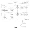
- Fig. 1 Figure 4 is a simplified block diagram of the essential components of a Magnetic Resonance Imaging (MRI) system which would be suitable for use with an antenna array described in this invention.
- MRI Magnetic Resonance Imaging
- the system consists of a computer connected to a memory unit and an interface unit.
- a radio frequency (RF) transmitter, an RF receiver and power supplies for the gradients are connected to the computer via the interface unit.
- RF radio frequency
- the power supply of the gradients supplies the gradient coils which generate the magnetic fields Gx, Gy and Gz with a gradient in X, Y and Z direction over the object to be imaged.
- the RF transmitter is triggered by the computer via pulses and thus generates the RF pulses of appropriate modulation in order to excite an MR signal in the object.
- the RF pulses are amplified in an RF power amplifier to powers between a few hundred watts to several kilowatts, depending on the imaging method, and applied to the transmitting antenna. Higher powers are needed for larger sample volumes, such as full-body MR imaging and where short pulses are needed to excite large NMR frequency bandwidths.
- the RF pulses emitted by the transmitting antenna induce an MR signal in the object which is to be examined.
- the MR signal is received by receive antenna, amplified in a low noise preamplifier, and passed to the receiver where the signal is further processed (e.g., amplified, filtered, mixed, averaged, etc.).
- each of the receiving antennas is connected via a connecting cable with its own low-noise preamplifier, which in turn is connected to a separate receiver.
- the signal is then digitized and forwarded via the interface unit to the computer, where the signal is further processed.
- Preamplifiers and receivers are protected by active cut-off or passive filters from the high RF transmit pulses.
- the same antenna is used to transmit and receive the RF signals.
- a separate antenna may be used to transmit and receive the RF signal.
- the magnetic field B1 generated by the antennas is orthogonal to the static magnetic field B0.
- the gradient coils generate magnetic field gradients Gx Gy and Gz which are monotonic and as linear as possible over the sample volume.
- Non-monotone gradient fields above the sample volume create artifacts in the MR image known as aliasing.
- Nonlinear gradients produce geometric distortions of the MR image.
- MRI systems are used to generate images of different body regions of individuals of different sizes. For this reason, a wide variety of receiving antennas are needed, which accordingly also have to be changed frequently. Switching the receive antennas is time consuming and the purchase of separate receive antennas for each application is very expensive.
- the present invention now describes an antenna system consisting of several individual antennas, which can be assembled in a modular manner and thus form a phased array antenna.
- the antenna arrangement which belongs to a magnetic resonance apparatus and is constructed as a phased array, will now be described below.
- the antenna arrangement comprises at least two individual antennas, wherein the individual antennas are interconnected by decoupling elements, characterized in that only the Decoupling elements are fixedly fixed to a carrier body, and the individual antennas are each combined in separate modules, which can be positioned on the carrier body, fixed, and non-destructively removed therefrom.
- the geometry suitable for the object to be imaged can be assembled in a modular manner.
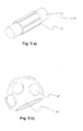
- Fig. 4 a represents said antenna system according to the present invention, when the individual antennas are mounted on the carrier body.
- Fig. 4b) represents a carrier body without individual antenna modules dar.
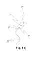
- Fig. 4c represents a single antenna module.
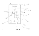
- FIG Fig. 3 A schematic representation of a single antenna module is shown in FIG Fig. 3 given.
- the individual antenna consists at least of a conductor loop, a tuning network, a matching network and preferably a detuning network, wherein the tuning network at least one tuning capacity, the matching network at least one matching capacity and the detuning network preferably at least one Contains diode.
- the individual antenna itself is located in a rigid housing.
- the housing is designed such that it can be positioned and fastened on the carrier body described below. In the concrete case described here, this comprises two bores for receiving positioning pins of the carrier body and a hole through which the individual antenna module can be fastened with a knurled screw on the carrier body.
- this comprises two bores for receiving positioning pins of the carrier body and a hole through which the individual antenna module can be fastened with a knurled screw on the carrier body.
- other possibilities of positioning and fixing the individual antenna modules on the carrier body are also conceivable.
- the carrier body defines the geometry of the antenna array.
- the carrier body is made of MR-compatible, stable material (eg glass fiber reinforced epoxy resin).
- the carrier has a planar geometry.
- the geometry of the carrier body is not limited to this, but may instead have any geometry adapted to the geometry of the object to be imaged.
- FIG. 5 a) & b) Further possible geometries for support bodies are shown.
- FIG. 5 a) FIG. 12 illustrates a cylindrical support body as would be used, for example, for an antenna configuration such as would be used to generate whole-body MRI images or MRI images of extremities.
- Fig. 5b represents an approximately spherical support body a cutout as it would be used to generate head MRI images.
- devices for fastening the carrier body to the object to be imaged such as (elastic) bands, hook-and-loop fasteners, snap closures or the like, are also attached to the carrier body.
- there are several devices on the support body which serve for fastening and positioning of the individual antennas on the carrier body.
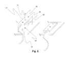
- Fig. 6 is a simple embodiment of such a device for attachment and positioning of a single antenna shown on the support body, consisting of two pins in the carrier body, which fit into two holes in the antenna module and this so positioned relative to the carrier body and a thumbscrew, with which the Einzelantennenmodul on the carrier body can be fixed. By loosening the thumbscrew, the single antenna module can be easily detached again from the carrier body and optionally attached to another carrier body.
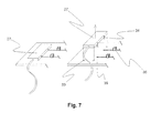
- decoupling elements on the carrier body, which serve to minimize the coupling between the individual antenna modules.
- said decoupling elements consist of contact sleeves, short traces and capacitances.
- Fig. 7 shown in more detail.
- the individual antenna module there are electrical contact pins, which are introduced into the corresponding contact sleeves on the carrier body when the individual antenna module is fastened to the carrier body. This creates an electrical connection between the individual antenna module and the conductor tracks on the carrier body.
- the individual antenna modules are electrically connected to each other in an advantageous manner. 'Advantageously' means that the coupling of the adjacent individual antenna modules is minimized in this way.
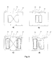
- Fig. 8 is the use of different carrier body and the idea of belonging to the carrier body decoupling again shown somewhat more schematically.
- FIG. 8 a) and Fig. 8 b) put two different Suspringper there.
- the carrier body shown in FIG Fig. 8b) In this case, the distance between the individual antenna modules is smaller than that of the carrier body shown in FIG Fig. 8 a) , The coupling of two antennae lying closer together is greater, which is why the decoupling capacitances which are on the carrier body in Fig. 8b) have a higher capacitance value than the decoupling capacitances on carrier bodies in FIG Fig. 8 a) .
- Fig. 8 c) and d) now set the respective carrier body Fig. 8 a) and b) with mounted individual antenna modules.
- Fig. 9 a) and b) represent a further possible embodiment of the invention.
- Fig. 9 a) and Fig. 9 b) put two different Collinsköper there.
- the carrier body shown in FIG Fig. 9b) In this case, the distance between the individual antenna modules is smaller than that of the carrier body shown in FIG Fig. 9 a) ,
- the decoupling elements on the carrier bodies now only consist of a closed strip conductor in the form of a butterfly and does not have to be electrically contacted with the individual antenna modules.
- the advantage of this embodiment of the decoupling elements is the fact that no galvanic contact between individual antenna module and decoupling element is necessary.
- the idea of using a conductor loop in the form of a butterfly as a decoupling element is not new, and will be described in detail in detail DE102 44 172 A1 described. Again, the coupling of two antennas closer together is larger. To compensate for the coupling of the two individual antennas, for this reason, the butterfly antenna in Fig. 9d) overlap the single antenna module slightly more than the butterfly antenna in Fig. 9c) ,
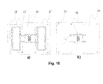
- Fig. 10 a) and b) represent a further possible embodiment of the invention.
- the decoupling element is designed as a transformer.
- Fig. 10 a) represents the carrier body with the transformer mounted thereon.
- Fig. 10b) two attached to the carrier body antenna modules are shown, which are contacted with the terminals of the transformer and decoupled therewith.
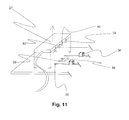
- a coding element is additionally present on the carrier body for each individual antenna module.
- this coding element consists of a resistor.
- the size of the resistor is different depending on the position on the carrier body and depending on the carrier body geometry. That is to say the resistance value encodes carrier body geometry and individual antenna position on the carrier body.
- one or more capacitive elements of the individual antenna modules are realized as capacitance diodes.
- each capacitance diode can be adjusted by changing the voltage applied across the element. Further, there is an electrical connection between the two terminals of each capacitance diode and a respective voltage source controlled by the computer. This device makes it possible with the method described below to set specific capacitance values of the various individual antenna modules as a function of the carrier body geometry and the position of the individual antenna module on the carrier body.
- the voltage values entered in the list have been determined previously and once so that changes in the adaptation of the individual resonant circuits resulting from the different arrangement of the individual antenna modules are corrected.
- the task was the MRI examination of abdomen of mice.
- a phased array antenna with 6 individual elements can be used, which are arranged on a cylindrical surface. This is in Fig. 5 ) a) shown schematically.
- the cylinder can now be selected, in which the mouse to be examined just barely fits. On this carrier body then the 6 antenna modules are attached. This gives you the desired 6x phased array antenna in the optimal size for the desired examination.
- the decoupling elements fastened on the carrier body ensure that the individual antennas are decoupled as well as possible.
Abstract
Description
Die Erfindung betrifft eine Antennenanordnung zur Verwendung in einem Magnetresonanzgerät, die als phasengesteuertes Array aufgebaut ist und mindestens zwei Einzelantennen umfasst, welche jeweils mindestens eine Leiterschleife, ein Tuning-Netzwerk und ein Matching-Netzwerk aufweisen, wobei das Tuning-Netzwerk mindestens eine Tuning-Kapazität und das Matching-Netzwerk mindestens eine Matching-Kapazität enthält, und die Einzelantennen jeweils in separaten Modulen zusammengefasst sind, die auf einem Trägerkörper positioniert, befestigt und zerstörungsfrei von dort wieder entfernt werden können.The invention relates to an antenna arrangement for use in a magnetic resonance apparatus, which is constructed as a phased array and comprises at least two individual antennas, each having at least one conductor loop, a tuning network and a matching network, wherein the tuning network at least one tuning capacity and the matching network contains at least one matching capacity, and the individual antennas are each combined in separate modules, which can be positioned on a support body, attached and non-destructively removed therefrom.
Eine solche Antennenanordnung ist aus der
Die Erfindung bezieht sich auf eine Abbildungsvorrichtung zur Nutzung der magnetischen Kernresonanz (NMR oder MR) unter Verwendung von Antennen (Spulen), die dem Senden und/oder Empfangen von Frequenzsignalen (Larmor-Frequenz) dienen und die in Arrays (Feldern) zusammengefasst sind, wobei die einzelne Antenne aus einer Leiterbahn besteht, die eine Fläche definiert.The invention relates to an imaging device for the use of nuclear magnetic resonance (NMR or MR) using antennas (coils) which serve to transmit and / or receive frequency signals (Larmor frequency) and which are combined in arrays (fields), wherein the single antenna consists of a track defining an area.
Die Nutzung der magnetischen Kernresonanz hat als ein wichtiges bildgebendes Verfahren weite Verbreitung gefunden. Hierbei wird der Effekt genutzt, dass Kernspins in einem homogenen magnetischen Feld (B0) bei Zuführung von Energie vermittels elektromagnetischer Wellen bestimmter Frequenzen, aufgrund von Absorption eine Anregung erfahren. Die Frequenz bestimmt sich dabei aus der Stärke des konstanten Magnetfeldes (B0) und den speziellen charakteristischen Eigenschaften des Kernes. Nach kurzer Zeit kehren die angeregten Spins in ihren Grundzustand, also einen tieferen Energiezustand zurück und emittieren ein elektromagnetisches hochfrequentes Signal, dass über Empfangsantennen erfasst und zur Konstruktion eines Bildes genutzt werden kann. Grundsätzlich können die gleichen Antennenelemente zur Anregung (Senden) eines Signals als auch zum Empfang genutzt werden. Es ist möglich mehrere Antennen in so genannten Arrays zusammenzufassen. Je größer die Dichte, also die Anzahl der einzelnen Antennen pro Flächeneinheit, umso besser wird das Signal-/Rausch- Verhältnis (SNR). Damit kann zum Beispiel die Auflösung des hergeleiteten Bildes erhöht werden. Ein weiterer wichtiger Vorzug von Antennenarrays ist die Möglichkeit der Nutzung parallelbildgebender Verfahren sie z.B. SENSE oder GRAPPA. Mit diesen Verfahren lässt sich eine höhere Aufnahmegeschwindigkeit realisieren.The use of nuclear magnetic resonance has been widely used as an important imaging technique. In this case, the effect is exploited that nuclear spins in a homogeneous magnetic field (B0) when supplied with energy by means of electromagnetic waves of certain frequencies, due to absorption excitation. The frequency is determined by the strength of the constant magnetic field (B0) and the special characteristics of the core. After a short time, the excited spins return to their ground state, ie a lower energy state and emit an electromagnetic high-frequency signal that can be detected via receiving antennas and used to construct an image. In principle, the same antenna elements can be used for excitation (transmission) of a signal as well as for reception. It is possible to combine multiple antennas in so-called arrays. The greater the density, ie the number of individual antennas per unit area, the better the signal-to-noise ratio (SNR). Thus, for example, the resolution of the derived image can be increased. Another important advantage of antenna arrays is the possibility of Use of parallel imaging techniques such as SENSE or GRAPPA. With these methods, a higher recording speed can be realized.
Die vorliegende Erfindung betrifft ein Antennenarray bestehend aus mehreren Einzelantennen.The present invention relates to an antenna array consisting of several individual antennas.
Bei der medizinischen Bildgebung mittels NMR werden hochfrequente Magnetfelder im MHz-Bereich aus dem menschlichen oder tierischen Körper mit einer HF-Antenne empfangen und zur Bildgebung weiter verarbeitet.In medical imaging by NMR, high-frequency magnetic fields in the MHz range from the human or animal body are received with an RF antenna and further processed for imaging.
Im Vergleich zum Empfang mit einer Ganzkörperantenne wird mit einer Empfangsantenne welche als Oberflächenantenne (Lokalantennen oder Lokalspulen) ausgebildet ist, welche der Oberfläche des Objektes und dem zu untersuchenden Gebiet angepasst ist, ein höheres Signal zu Rausch Verhältnis (SNR) im MR-Bild erzielt.Compared with reception with a whole-body antenna, a higher signal-to-noise ratio (SNR) in the MR image is achieved with a receiving antenna which is designed as a surface antenna (local antenna or local coil) which is adapted to the surface of the object and the area to be examined.
Eine kleinere Oberflächenantenne bringt dabei ein höheres SNR als eine größere Oberflächenantenne, hat aber auch ein dementsprechend kleineres Field-of-View (FOV, abgebildeter Bereich). Wenn nun ein größeres FOV untersucht werden soll, wird aus diesem Grund anstelle einer einzelnen großen Antenne häufig mit einer Vielzahl von kleineren Antennen bzw. mit einem Array von kleineren Antennen gearbeitet. Dabei benötigt jede einzelne Empfangsantenne ihren eigenen Empfangspfad bestehend aus Vorverstärker, Kabel und Empfänger. Vorrichtungen dieser Arte werden als Phased-Array-Antennen oder Antennenarrays bezeichnet.A smaller surface antenna will have a higher SNR than a larger surface antenna, but will also have a correspondingly smaller field-of-view (FOV, mapped area). For this reason, if a larger FOV is to be investigated, a large number of smaller antennas or an array of smaller antennas are frequently used instead of a single large antenna. Every single receiving antenna needs its own receiving path consisting of preamplifier, cable and receiver. Devices of this type are referred to as phased array antennas or antenna arrays.
Die Einzelantennen sind dabei im Allgemeinen auf einer Fläche angeordnet, die der Geometrie des Untersuchungsgebietes angepasst ist.The individual antennas are generally arranged on a surface that is adapted to the geometry of the study area.
Ein Problem bei Antennenarrays ist die Tatsache, dass mit mehreren nebeneinander angeordneten Einzelantennen ein Hochfrequenzstrom in einer der Einzelantennen eine Spannung in benachbarten Einzelantennen induzieren kann. Dies wird als Verkopplung (Kopplung) von Antennen untereinander bezeichnet wird. Verkopplungen treten sowohl bei Anordnungen von zirkular polarisierten Antennen als auch bei Anordnungen von linear polarisierten Einzelantennen auf. Verkopplungen verschlechtern das Signal-Rauschverhältnis (SNR) und erzeugt Artefakte im MR-Bild. Zudem ist der Aufwand für die Prüfung von verkoppelten Einzelantennen größer als für die Prüfung von nicht verkoppelten Einzelantennen. Ein Ziel beim Design von Phased-Array-Antennen ist deshalb, eine Verkopplung der Einzelantennen möglichst zu vermeiden.One problem with antenna arrays is the fact that, with several juxtaposed individual antennas, a high-frequency current in one of the individual antennas can induce a voltage in adjacent individual antennas. This is referred to as coupling (coupling) of antennas with each other. Couplings occur both in arrangements of circularly polarized antennas and in arrangements of linearly polarized individual antennas. Couplings degrade the signal-to-noise ratio (SNR) and produce artifacts in the MR image. In addition, the effort for the testing of coupled individual antennas is greater than for the testing of uncoupled individual antennas. One goal in the design of phased array antennas is therefore to avoid coupling the individual antennas as much as possible.
Ein Antennenarray der eingangs genannten Art ist in der
In der vorstehend bereits zitierten
Ein weiteres Antennenarray ist in der
In der
In der
In der
Um die Einzelantennen auf einer Fläche anzuordnen, welch der Geometrie des Untersuchungsgebietes möglichst gut angepasst ist, werden mit Vorteil flexible Antennen eingesetzt.In order to arrange the individual antennas on a surface which is adapted as well as possible to the geometry of the examination area, flexible antennas are advantageously used.
So beschreibt
Eine andere Möglichkeit eine Phased-Array-Antenne der Geometrie des abzubildenden Objektes anzupassen ist es, die Phased-Array-Antenne modular aufzubauen, sodass die Einzelantennen der Phased-Array-Antenne entsprechend der gewünschten Geometrie angeordnet werden können. Ein Antennensystem dieser Art ist in
Alle diesen Lösungsansätzen ist jedoch ein Problem gemeinsam. Durch Verformen eines Antennenarrays bzw. durch umplatzieren von einzelnen Antennen eines Antennenarrays ändert sich die gegenseitige Kopplung der Einzelantennen, was dazu führt dass die Entkopplungselemente nachgeregelt werden müssen um die Kopplung der Einzelantennen wieder zu minimieren.However, all these approaches have one problem in common. By deforming an antenna array or by repositioning of individual antennas of an antenna array, the mutual coupling of the individual antennas changes, which means that the decoupling must be readjusted to minimize the coupling of the individual antennas again.
Ziel der erfindungsgemäßen Vorrichtung ist es, Einzelantennenmodule zu definieren, die auf einfache Weise um das Messvolumen herum angeordnet werden können und zugleich untereinander elektromagnetisch entkoppelt sind, und die vorzugsweise dicht am Messvolumen positioniert werden können, damit das empfangene MRI-Bild ein möglichst hohes Signal-zu-Rauschverhältnis besitzt.The aim of the device according to the invention is to define individual antenna modules which can be arranged in a simple manner around the measurement volume and at the same time are electromagnetically decoupled from one another, and which can preferably be positioned close to the measurement volume, so that the received MRI image has as high a signal as possible. has to-noise ratio.
Erreicht wird dieses Ziel dadurch, dass die Einzelantennen durch Entkopplungselemente miteinander verbunden sind, und dass die Entkopplungselemente am Trägerkörper befestigt sind und von diesem nicht entfernt werden können.This goal is achieved in that the individual antennas are interconnected by decoupling elements, and that the decoupling elements are attached to the support body and can not be removed from this.
- 1. die Phased-Array-Antenne in irgendeiner Form flexibel ist, damit alle Einzelantennen des Arrays möglichst nahe am Objekt positioniert werden können und die Phased-Array-Antenne so möglichst gut auf eine Vielzahl von verschiedenen Objektgrößen und -formen passt.1. The phased array antenna is flexible in some form, so that all the individual antennas of the array can be positioned as close to the object as possible and the phased array antenna fits as well as possible to a variety of different object sizes and shapes.
-
2. die unter Punkt 1 beschriebene Flexibilität derart erreicht wird, dass die Einzelelemente der Phased-Array-Antenne nicht verformt werden müssen.2. The flexibility described in
point 1 is achieved in such a way that the individual elements of the phased array antenna need not be deformed. -
3. die Entkopplung der Einzelantennen trotz der unter Punkt 1 beschriebenen Flexibilität gewährleistet ist.3. the decoupling of the individual antennas is guaranteed despite the flexibility described in
point 1.
In der vorliegenden Erfindung werden die oben aufgelisteten Ziele dadurch erreicht, dass man sich einer Antennenanordnung, die zu einem Magnetresonanzgerät gehört und als phasengesteuertes Array aufgebaut ist, bedient, wobei die Antennenanordnung mindestens zwei Einzelantennen umfasst, welche jeweils aus mindestens einer Leiterschleife, einem Tuning-Netzwerk, einem Matching-Netzwerk sowie vorzugsweise einem Detuning-Netzwerk aufgebaut ist, wobei das Tuning-Netzwerk mindestens eine Tuningkapazität, das Matching-Netzwerk mindestens eine Matching-Kapazität und das Detuning-Netzwerk vorzugsweise mindestens eine Diode enthält, und wobei die Einzelantennen durch Entkopplungselementen miteinander verbunden sind, dadurch gekennzeichnet, dass nur die Entkopplungselemente fix an einem Trägerkörper befestigt sind, und die Einzelantennen jeweils in separaten Modulen zusammengefasst sind, die am Trägerkörper positioniert, befestigt, und zerstörungsfrei von dort wieder entfernt werden können. Durch bereitstellen unterschiedlicher Trägerkörper kann die passende Geometrie in modularer Weise zusammengebaut werden. In the present invention, the objectives listed above are achieved by serving an antenna arrangement which belongs to a magnetic resonance apparatus and is constructed as a phased array, wherein the antenna arrangement comprises at least two individual antennas, each consisting of at least one conductor loop, a tuning Network, a matching network and preferably a detuning network is constructed, wherein the tuning network at least one tuning capacity, the matching network at least one matching capacity and the detuning network preferably at least one diode, and wherein the individual antennas by decoupling elements connected to each other, characterized in that only the decoupling elements are fixedly secured to a carrier body, and the individual antennas are each combined in separate modules, which can be positioned on the carrier body, fixed, and non-destructively be removed from there again NEN. By providing different support bodies, the appropriate geometry can be modularly assembled.
Das System besteht aus einem Computer, welcher mit einer Speichereinheit und einer Schnittstelleneinheit verbunden ist.The system consists of a computer connected to a memory unit and an interface unit.
Ein Hochfrequenz (HF) Transmitter, ein HF - Empfänger und Stromversorgungen für die Gradienten, sind über die Schnittstelleneinheit mit dem Computer verbunden.A radio frequency (RF) transmitter, an RF receiver and power supplies for the gradients are connected to the computer via the interface unit.
Die Stromversorgung der Gradienten versorgt die die Gradientenspulen, welche die Magnetfelder Gx, Gy und Gz mit einem Gradienten in X, Y und Z-Richtung über dem abzubildenden Objekt erzeugen.The power supply of the gradients supplies the gradient coils which generate the magnetic fields Gx, Gy and Gz with a gradient in X, Y and Z direction over the object to be imaged.
Der HF - Transmitter wird über Pulse vom Computer getriggert und erzeugt so die HF-Pulse entsprechender Modulierung um ein MR-Signal im Objekt anzuregen.The RF transmitter is triggered by the computer via pulses and thus generates the RF pulses of appropriate modulation in order to excite an MR signal in the object.
Die HF-Pulse werden in einem HF - Leistungsverstärker auf Leistungen zwischen einigen hundert Watt bis mehreren Kilowatt, abhängig von der Bildgebungsmethode, verstärkt und auf die Sendeantenne gegeben.
Höhere Leistungen werden für größere Samplevolumen benötigt, wie z.B. bei der Erzeugung von Ganzkörper MR-Bildern und dort, wo kurze Pulse benötigt werden um große NMR Frequenzbandbreiten anzuregen.The RF pulses are amplified in an RF power amplifier to powers between a few hundred watts to several kilowatts, depending on the imaging method, and applied to the transmitting antenna.
Higher powers are needed for larger sample volumes, such as full-body MR imaging and where short pulses are needed to excite large NMR frequency bandwidths.
Die von der Sendeantenne abgestrahlten HF-Pulse induzieren ein MR-Signal im Objekt, welches untersucht werden soll.The RF pulses emitted by the transmitting antenna induce an MR signal in the object which is to be examined.
Das MR - Signal wird von Empfangsantenne empfangen, in einem rauscharmen Vorverstärker verstärkt und zum Empfänger weitergeleitet, wo das Signal weiter prozessiert (z.B. weiter verstärkt, gefiltert, gemischt, gemittelt usw.) wird.The MR signal is received by receive antenna, amplified in a low noise preamplifier, and passed to the receiver where the signal is further processed (e.g., amplified, filtered, mixed, averaged, etc.).
In einer alternativen Anordnung existieren mehrere Empfangsantennen jede der Empfangsantennen ist dabei über ein Verbindungskabel mit einem eigenen rauscharmen Vorverstärker verbunden, welcher wiederum an einen eigenen Empfänger verbunden ist.In an alternative arrangement, there are several receiving antennas each of the receiving antennas is connected via a connecting cable with its own low-noise preamplifier, which in turn is connected to a separate receiver.
Das Signal wird dann digitalisiert und über die Schnittstelleneinheit an den Computer weitergeleitet, wo das Signal weiter prozessiert wird.The signal is then digitized and forwarded via the interface unit to the computer, where the signal is further processed.
Vorverstärker und Empfänger werden durch aktives Wegschalten oder passive Filter von den hohen HF-Sendepulsen geschützt.Preamplifiers and receivers are protected by active cut-off or passive filters from the high RF transmit pulses.
In einigen MR - Systemen wird zum Senden und Empfangen der HF - Signale dieselbe Antenne verwendet. Alternativ kann zum Senden und Empfangen des HF - Signals jeweils eine separate Antenne verwendet werden. In beiden Fällen ist das von den Antennen erzeugte magnetische Feld B1 orthogonal zum statischen Magnetfeld B0.In some MR systems, the same antenna is used to transmit and receive the RF signals. Alternatively, a separate antenna may be used to transmit and receive the RF signal. In both cases, the magnetic field B1 generated by the antennas is orthogonal to the static magnetic field B0.
Die Gradientenspulen erzeugen Magnetfeldgradienten Gx Gy und Gz welche monoton und möglichst linear über dem Samplevolumen sind. Nicht monotone Gradientenfelder über dem Samplevolumen erzeugen Artefakte im MR - Bild, welche als ,Aliasing' bekannt sind. Nichtlineare Gradienten erzeugen geometrische Verzerrungen des MR-Bildes.The gradient coils generate magnetic field gradients Gx Gy and Gz which are monotonic and as linear as possible over the sample volume. Non-monotone gradient fields above the sample volume create artifacts in the MR image known as aliasing. Nonlinear gradients produce geometric distortions of the MR image.
In der klinischen Anwendung werden MRI-Systeme benutzt um Bilder von verschiedenen Körperregionen von Individuen unterschiedlichster Größe zu erzeugen. Aus diesem Grund werden unterschiedlichster Empfangsantennen benötigt, welche dementsprechend auch häufig gewechselt werden müssen. Das Wechseln der Empfangsantennen ist zeitraubend und die Anschaffung separater Empfangsantennen für jede Anwendung ist sehr teuer.In clinical application, MRI systems are used to generate images of different body regions of individuals of different sizes. For this reason, a wide variety of receiving antennas are needed, which accordingly also have to be changed frequently. Switching the receive antennas is time consuming and the purchase of separate receive antennas for each application is very expensive.
Die vorliegende Erfindung beschreibt nun ein Antennensystem bestehend aus mehreren Einzelantennen, welche in modularer Weise zusammengesetzt werden können und so eine Phased-Array-Antenne bilden.The present invention now describes an antenna system consisting of several individual antennas, which can be assembled in a modular manner and thus form a phased array antenna.
Im Folgenden ist nun die erfindungsgemäße Antennenanordnung, die zu einem Magnetresonanzgerät gehört und als phasengesteuertes Array aufgebaut ist, beschrieben. Die Antennenanordnung umfasst dabei mindestens zwei Einzelantennen, wobei die Einzelantennen durch Entkopplungselementen miteinander verbunden sind, dadurch gekennzeichnet, dass nur die Entkopplungselemente fix an einem Trägerkörper befestigt sind, und die Einzelantennen jeweils in separaten Modulen zusammengefasst sind, die am Trägerkörper positioniert, befestigt, und zerstörungsfrei von dort wieder entfernt werden können.The antenna arrangement according to the invention, which belongs to a magnetic resonance apparatus and is constructed as a phased array, will now be described below. The antenna arrangement comprises at least two individual antennas, wherein the individual antennas are interconnected by decoupling elements, characterized in that only the Decoupling elements are fixedly fixed to a carrier body, and the individual antennas are each combined in separate modules, which can be positioned on the carrier body, fixed, and non-destructively removed therefrom.
Durch Bereitstellen unterschiedlicher Trägerkörper kann damit die zum abzubildenden Objekt passende Geometrie in modularer Weise zusammengebaut werden.By providing different carrier bodies, the geometry suitable for the object to be imaged can be assembled in a modular manner.
Eine schematische Darstellung eines Einzelantennenmodules ist in
Der Trägerkörper, dargestellt in
Zweckmäßigerweise sind am Trägerkörper auch Vorrichtungen zur Befestigung des Trägerkörpers am abzubildenden Objekt, wie (elastische) Bänder, Klettverschlüsse, Schnappverschlüsse oder ähnliches angebracht. In jedem Fall befinden sich auf dem Trägerkörper jedoch mehrere Vorrichtungen, welche zur Befestigung und Positionierung der Einzelantennen auf dem Trägerkörper dienen. In
In jedem Fall befinden sich auf dem Trägerkörper auch Entkopplungselemente, welche zur Minimierung der Kopplung zwischen den Einzelantennenmodulen dienen. In der konkreten Ausführung, welche in
In
Die Entkopplungselemente auf den Trägerkörpern bestehen hier nun lediglich aus einer geschlossenen Leiterbahn in Schmetterlingsform und muss nicht elektrisch mit den Einzelantennenmodulen kontaktiert werden. Vorteil dieser Ausführung der Entkopplungselemente ist die Tatsache, dass kein galvanischer Kontakt zwischen Einzelantennenmodul und Entkopplungselement nötig ist. Die Idee eine Leiterschleife in Schmetterlingsform als Entkopplungselement zu verwenden ist dabei nicht neu, und wird unter anderem ausführlich in
In einer etwas komplizierteren Ausführung der hier vorliegenden Erfindung ist auf dem Trägerkörper neben den oben beschriebenen Elementen für jedes Einzelantennenmodul zusätzlich noch ein Codierelement vorhanden. Im konkreten in
D.h. die Kapazität dieser Elemente kann durch Änderung der über dem Element angelegten Spannung eingestellt werden. Weiter existiert eine elektrische Verbindung zwischen den beiden Anschlüssen jeder Kapazitätsdiode und je einer vom Computer gesteuerten Spannungsquelle. Diese Vorrichtung erlaubt es mit dem im Folgenden beschriebenen Verfahren bestimmte Kapazitätswerte der verschiedenen Einzelantennenmodule abhängig von der Trägerkörpergeometrie und der Position des Einzelantennenmodules auf dem Trägerkörper einzustellen.That the capacitance of these elements can be adjusted by changing the voltage applied across the element. Further, there is an electrical connection between the two terminals of each capacitance diode and a respective voltage source controlled by the computer. This device makes it possible with the method described below to set specific capacitance values of the various individual antenna modules as a function of the carrier body geometry and the position of the individual antenna module on the carrier body.
Ein Verfahren, wie mit oben beschriebener Vorrichtung die Kapazitätsdioden in den Einzelantennenmodulen eingestellt werden kann:
- Jedes Codierelement auf dem Trägerkörper wird über die jeweilige elektrische Verbindung vom Computer ausgelesen und mit einer zuvor erzeugten Liste von Widerstandswerten verglichen. Diese Liste ordnet in eindeutiger Weise jedem Widerstandswert einen Spannungswert zu. Der Computer steuert nun die entsprechenden Spannungsquellen so, dass über den jeweiligen Kapazitätsdioden die entsprechenden Spannungen anliegen, wodurch die Kapazitätsdioden einen bestimmten Kapazitätswert annehmen.
- Each coding element on the carrier body is read by the computer via the respective electrical connection and compared with a previously generated list of resistance values. This list uniquely assigns a voltage value to each resistance value. The computer now controls the corresponding voltage sources so that the corresponding voltages are present across the respective capacitance diodes, whereby the capacitance diodes assume a specific capacitance value.
Die in der Liste eingetragenen Spannungswerte wurden vorgängig und einmalig so bestimmt, dass Veränderungen in der Anpassung der einzelnen Schwingkreise, welche sich durch die unterschiedliche Anordnung der Einzelantennenmodule ergeben, korrigiert werden.The voltage values entered in the list have been determined previously and once so that changes in the adaptation of the individual resonant circuits resulting from the different arrangement of the individual antenna modules are corrected.
Im Folgenden sein nun ein konkretes Beispiel der oben beschriebenen Erfindung gegeben.In the following, a concrete example of the invention described above will now be given.
Aufgabe sei die MRI-Untersuchung von Abdomen von Mäusen.The task was the MRI examination of abdomen of mice.
Dazu kann eine Phased-Array-Antenne mit 6 Einzelelementen verwendet werden, welche auf einer Zylindermantel-Oberfläche angeordnet sind. Dies ist in
Um nun Spulen zu haben, welche auf unterschiedlich große Mäuse passen werden im Sinne der vorliegenden Erfindung 6 separate Einzelantennenmodule und ein Set von beispielsweise 3 Trägerkörpern unterschiedlicher Größe zur Verfügung gestellt.In order to have coils that fit differently sized mice, 6 separate antenna modules and a set of, for example, 3 bodies of different sizes are provided for the purposes of the present invention.
Aus dem Set von Trägerkörpern kann nun der Zylinder ausgewählt werden, in welchen die zu untersuchende Maus noch knapp hineinpasst. Auf diesem Trägerkörper werden anschließend die 6 Antennenmodule befestigt werden. Damit hat man die gewünschte 6-fach Phased-Array-Antenne in der optimalen Größe für die gewünschte Untersuchung.From the set of carrier bodies, the cylinder can now be selected, in which the mouse to be examined just barely fits. On this carrier body then the 6 antenna modules are attached. This gives you the desired 6x phased array antenna in the optimal size for the desired examination.
Die auf dem Trägerkörper befestigten Entkopplungselemente sorgen dabei dafür, dass die Einzelantennen möglichst gut entkoppelt sind.The decoupling elements fastened on the carrier body ensure that the individual antennas are decoupled as well as possible.
In der nachfolgenden Liste sind alle vorhandenen Abbildungen beschrieben:
- Fig.1
- Blockdiagramm MRI-System
- Fig.2
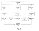
- Blockdiagramm Phased-Array-Antenne
- Fig.3
- Schematische Darstellung eines Einzelantennenmoduls
- Fig.4a
- Modulare MRI Phased-Array-Antenne
- Fig.4b
- Trägerköper einer modularen Phased-Array-Antenne
- Fig.4c
- Einzelantennen einer modularen Phased-Array-Antenne
- Fig.5
- Verschiedene Geometrien von Trägerkörpern
- Fig.6
- Vorrichtung zur Befestigung von Einzelantennen auf dem Trägerkörper
- Fig.7
- Entkopplungskapazitäten als Entkopplungselemente
- Fig.8
- Erfindungsgemäße Antennenanordnung mit Kapazitäten als Entkopplungselemente
- Fig.9
- Erfindungsgemäße Antennenanordnung mit Schmetterlingsantennen als Entkopplungselemente
- Fig.10
- Erfindungsgemäße Antennenanordnung mit Transformatoren als Entkopplungselemente
- Fig.11
- Trägerkörper mit Codierelement
- Fig.1
- Block diagram MRI system
- Fig.2
- Block diagram phased array antenna
- Figure 3
- Schematic representation of a single antenna module
- 4a
- Modular MRI phased array antenna
- 4b
- Carrier body of a modular phased array antenna
- 4c
- Single antennas of a modular phased array antenna
- Figure 5
- Different geometries of support bodies
- Figure 6
- Device for fixing individual antennas on the carrier body
- Figure 7
- Decoupling capacities as decoupling elements
- Figure 8
- Antenna arrangement according to the invention with capacities as decoupling elements
- Figure 9
- Antenna arrangement according to the invention with butterfly antennas as decoupling elements
- Figure 10
- Antenna arrangement according to the invention with transformers as decoupling elements
- Figure 11
- Carrier body with coding element
- [1]:[1]:
-
US 4,825,162US 4,825,162 - [2]:[2]:
-
DE 38 20 168 A1 DE 38 20 168 A1 - [3]:[3]:
-
US 5,216,368US 5,216,368 - [4]:[4]:
-
DE 41 13 120 C2 DE 41 13 120 C2 - [5]:[5]:
-
DE 10 2004 046 188 A1DE 10 2004 046 188 A1 - [6]:[6]:
-
DE 102 44 172 A1DE 102 44 172 A1 - [7]:[7]:
-
US 6,650,926 B1US Pat. No. 6,650,926 B1 - [8]:[8th]:
-
US 2008/0238424 A1US 2008/0238424 A1 - [9]:[9]:
-
US 6,084,411US 6,084,411
Claims (9)
dadurch gekennzeichnet,
dass die Einzelantennen durch Entkopplungselemente miteinander verbunden sind,
und dass die Entkopplungselemente am Trägerkörper befestigt sind und von diesem nicht entfernt werden können.Antenna arrangement for use in a magnetic resonance apparatus, which is constructed as a phased array and comprises at least two individual antennas, which each have at least one conductor loop, a tuning network and a matching network, wherein the tuning network has at least one tuning capacity and the matching network. Network contains at least one matching capacity, and the individual antennas are each combined in separate modules that can be positioned on a support body, attached and destroyed without destruction,
characterized,
that the individual antennas are interconnected by decoupling elements,
and that the decoupling elements are attached to the carrier body and can not be removed from this.
dadurch gekennzeichnet, dass die Anordnung ein Detuning-Netzwerk aufweist, welches mindestens eine Diode enthält.Antenna arrangement according to one of the preceding claims,
characterized in that the arrangement comprises a detuning network containing at least one diode.
dadurch gekennzeichnet, dass der Trägerkörper zusätzlich noch mit einem Codierelement ausgerüstet ist, welches die Spannungsversorgung von Kapazitätsdioden in den einzelnen Antennenelementen regelt.Antenna arrangement according to one of the preceding claims,
characterized in that the carrier body is additionally equipped with a coding element which controls the voltage supply of capacitance diodes in the individual antenna elements.
Applications Claiming Priority (1)
| Application Number | Priority Date | Filing Date | Title |
|---|---|---|---|
| DE102010038722A DE102010038722B4 (en) | 2010-07-30 | 2010-07-30 | Modular MRI phased array antenna |
Publications (2)
| Publication Number | Publication Date |
|---|---|
| EP2413155A1 true EP2413155A1 (en) | 2012-02-01 |
| EP2413155B1 EP2413155B1 (en) | 2013-03-13 |
Family
ID=44785189
Family Applications (1)
| Application Number | Title | Priority Date | Filing Date |
|---|---|---|---|
| EP11175518A Active EP2413155B1 (en) | 2010-07-30 | 2011-07-27 | Modular MRI phased array antenna |
Country Status (4)
| Country | Link |
|---|---|
| US (1) | US8692553B2 (en) |
| EP (1) | EP2413155B1 (en) |
| JP (1) | JP5611902B2 (en) |
| DE (1) | DE102010038722B4 (en) |
Cited By (1)
| Publication number | Priority date | Publication date | Assignee | Title |
|---|---|---|---|---|
| CN103576108A (en) * | 2012-08-07 | 2014-02-12 | 西门子公司 | Activation of transmit/receive arrays for decoupling during transmission |
Families Citing this family (4)
| Publication number | Priority date | Publication date | Assignee | Title |
|---|---|---|---|---|
| AU2010230843B2 (en) * | 2009-03-31 | 2015-04-30 | The University Of Queensland | Coil arrangement |
| US8970217B1 (en) | 2010-04-14 | 2015-03-03 | Hypres, Inc. | System and method for noise reduction in magnetic resonance imaging |
| DE102017213026A1 (en) * | 2017-07-28 | 2019-01-31 | Siemens Healthcare Gmbh | Gradient coil for generating a magnetic field gradient and a higher-order magnetic field |
| CN109856683B (en) * | 2019-01-07 | 2020-06-16 | 吉林大学 | Towed phased array electromagnetic detection device and method |
Citations (12)
| Publication number | Priority date | Publication date | Assignee | Title |
|---|---|---|---|---|
| US4825162A (en) | 1987-12-07 | 1989-04-25 | General Electric Company | Nuclear magnetic resonance (NMR) imaging with multiple surface coils |
| DE3820168A1 (en) | 1988-06-14 | 1989-12-21 | Philips Patentverwaltung | CORE SPIN EXAMINATION DEVICE WITH A CIRCUIT FOR UNCOUPLING THE BOTH COIL SYSTEMS OF A SQUARE COIL ARRANGEMENT |
| US5216368A (en) | 1990-11-10 | 1993-06-01 | U.S. Philips Corporation | Quadrature coil system |
| DE4113120C2 (en) | 1991-04-22 | 1993-09-23 | Siemens Ag, 80333 Muenchen, De | |
| US6084411A (en) | 1997-02-13 | 2000-07-04 | General Electric Company | Flexible lightweight attached phased-array (FLAP) receive coils |
| US6650926B1 (en) | 2001-03-30 | 2003-11-18 | Usa Instruments, Inc. | Flexible multi-section MRI radio frequency array coil |
| DE10244172A1 (en) | 2002-09-23 | 2004-03-11 | Siemens Ag | Magnetic resonance unit antenna has adjacent elements excited from figure of eight coupling loop to minimize inductive coupling |
| EP1521094A1 (en) * | 2003-10-01 | 2005-04-06 | Gore Enterprise Holdings, Inc. | Modular MR radio frequency coil array |
| DE102004046188A1 (en) | 2004-09-23 | 2006-04-06 | Siemens Ag | Antenna arrangement for receiving a magnetic resonance signal |
| US20070257670A1 (en) * | 2006-05-04 | 2007-11-08 | General Electric Company | Multi-channel low loss mri coil |
| WO2008073512A2 (en) * | 2006-06-09 | 2008-06-19 | Koninklijke Philips Electronics, N.V. | Integrated system of mri rf loop coil modules and spacing fixtures with biocontainment uses |
| US20080238424A1 (en) | 2005-10-19 | 2008-10-02 | Koninklijke Philips Electronics N. V. | Compact and Flexible Radio Frequency Coil Arrays |
Family Cites Families (19)
| Publication number | Priority date | Publication date | Assignee | Title |
|---|---|---|---|---|
| JPH01126532A (en) | 1987-11-10 | 1989-05-18 | Takeda Chem Ind Ltd | Polynuclear nmr probe for local measurement |
| JP2641808B2 (en) | 1991-01-31 | 1997-08-20 | 株式会社島津製作所 | MRI antenna coil |
| JP3167038B2 (en) | 1991-07-18 | 2001-05-14 | 株式会社日立メディコ | Magnetic resonance imaging equipment |
| US5329233A (en) * | 1992-12-10 | 1994-07-12 | General Electric Company | Cylindrical local coil for nuclear magnetic resonance imaging |
| US5594337A (en) * | 1993-05-07 | 1997-01-14 | Medical Advances, Inc. | Local coil for magnetic resonance angiography |
| US5351688A (en) * | 1993-08-16 | 1994-10-04 | Univ. Of Ne Board Of Regents | NMR quadrature detection solenoidal coils |
| US5578925A (en) * | 1995-08-18 | 1996-11-26 | Picker International, Inc. | Vertical field quadrature phased array coil system |
| JP4552291B2 (en) * | 2000-08-23 | 2010-09-29 | ソニー株式会社 | Information processing apparatus and method, and recording medium |
| US6591128B1 (en) * | 2000-11-09 | 2003-07-08 | Koninklijke Philips Electronics, N.V. | MRI RF coil systems having detachable, relocatable, and or interchangeable sections and MRI imaging systems and methods employing the same |
| EP1430323B1 (en) * | 2001-09-14 | 2011-03-09 | Koninklijke Philips Electronics N.V. | Mr coil module |
| US6992486B2 (en) * | 2002-05-16 | 2006-01-31 | Advanced Imaging Research, Inc. | Radio frequency coil for resonance imaging analysis of pediatric patients |
| US7215120B2 (en) * | 2002-05-17 | 2007-05-08 | Mr Instruments, Inc. | Cavity resonator for MR systems |
| DE10226511A1 (en) * | 2002-06-14 | 2003-12-24 | Philips Intellectual Property | MR arrangement with high-frequency coil arrays |
| JP2004033380A (en) | 2002-07-02 | 2004-02-05 | Ge Medical Systems Global Technology Co Llc | Radio frequency coil and magnetic resonance imaging device |
| WO2005078468A2 (en) * | 2004-01-20 | 2005-08-25 | The University Of Houston System | Superconducting loop, saddle and birdcage mri coils comprising built-in capacitors |
| US7659719B2 (en) * | 2005-11-25 | 2010-02-09 | Mr Instruments, Inc. | Cavity resonator for magnetic resonance systems |
| JP4866760B2 (en) | 2007-03-06 | 2012-02-01 | 株式会社日立メディコ | Magnetic resonance imaging system |
| US7772842B2 (en) * | 2008-09-17 | 2010-08-10 | Time Medical Holdings Company Limited | Dedicated superconductor MRI imaging system |
| US7728592B2 (en) * | 2008-09-17 | 2010-06-01 | Time Medical Holdings Company Limited | Integrated superconductor MRI imaging system |
-
2010
- 2010-07-30 DE DE102010038722A patent/DE102010038722B4/en not_active Expired - Fee Related
-
2011
- 2011-07-27 US US13/137,184 patent/US8692553B2/en active Active
- 2011-07-27 EP EP11175518A patent/EP2413155B1/en active Active
- 2011-07-29 JP JP2011166641A patent/JP5611902B2/en active Active
Patent Citations (12)
| Publication number | Priority date | Publication date | Assignee | Title |
|---|---|---|---|---|
| US4825162A (en) | 1987-12-07 | 1989-04-25 | General Electric Company | Nuclear magnetic resonance (NMR) imaging with multiple surface coils |
| DE3820168A1 (en) | 1988-06-14 | 1989-12-21 | Philips Patentverwaltung | CORE SPIN EXAMINATION DEVICE WITH A CIRCUIT FOR UNCOUPLING THE BOTH COIL SYSTEMS OF A SQUARE COIL ARRANGEMENT |
| US5216368A (en) | 1990-11-10 | 1993-06-01 | U.S. Philips Corporation | Quadrature coil system |
| DE4113120C2 (en) | 1991-04-22 | 1993-09-23 | Siemens Ag, 80333 Muenchen, De | |
| US6084411A (en) | 1997-02-13 | 2000-07-04 | General Electric Company | Flexible lightweight attached phased-array (FLAP) receive coils |
| US6650926B1 (en) | 2001-03-30 | 2003-11-18 | Usa Instruments, Inc. | Flexible multi-section MRI radio frequency array coil |
| DE10244172A1 (en) | 2002-09-23 | 2004-03-11 | Siemens Ag | Magnetic resonance unit antenna has adjacent elements excited from figure of eight coupling loop to minimize inductive coupling |
| EP1521094A1 (en) * | 2003-10-01 | 2005-04-06 | Gore Enterprise Holdings, Inc. | Modular MR radio frequency coil array |
| DE102004046188A1 (en) | 2004-09-23 | 2006-04-06 | Siemens Ag | Antenna arrangement for receiving a magnetic resonance signal |
| US20080238424A1 (en) | 2005-10-19 | 2008-10-02 | Koninklijke Philips Electronics N. V. | Compact and Flexible Radio Frequency Coil Arrays |
| US20070257670A1 (en) * | 2006-05-04 | 2007-11-08 | General Electric Company | Multi-channel low loss mri coil |
| WO2008073512A2 (en) * | 2006-06-09 | 2008-06-19 | Koninklijke Philips Electronics, N.V. | Integrated system of mri rf loop coil modules and spacing fixtures with biocontainment uses |
Cited By (3)
| Publication number | Priority date | Publication date | Assignee | Title |
|---|---|---|---|---|
| CN103576108A (en) * | 2012-08-07 | 2014-02-12 | 西门子公司 | Activation of transmit/receive arrays for decoupling during transmission |
| CN103576108B (en) * | 2012-08-07 | 2016-04-13 | 西门子公司 | Control sending/receiving array for decoupling in the transmitting case |
| US9395427B2 (en) | 2012-08-07 | 2016-07-19 | Siemens Aktiengesellschaft | Activation of transmit/receive arrays for decoupling during transmission |
Also Published As
| Publication number | Publication date |
|---|---|
| JP5611902B2 (en) | 2014-10-22 |
| US20120025832A1 (en) | 2012-02-02 |
| DE102010038722A1 (en) | 2012-02-02 |
| JP2012030076A (en) | 2012-02-16 |
| US8692553B2 (en) | 2014-04-08 |
| EP2413155B1 (en) | 2013-03-13 |
| DE102010038722B4 (en) | 2012-10-31 |
Similar Documents
| Publication | Publication Date | Title |
|---|---|---|
| EP0352824B1 (en) | Local coil arrangement for NMR examination | |
| DE4113120C2 (en) | ||
| DE4232884C2 (en) | Antenna arrangement for a nuclear magnetic resonance device | |
| DE102012207722B3 (en) | Whole-body coil for MRI apparatus e.g. functional MRI apparatus used for performing investigation of patient, has radio frequency antenna whose capacitance is changed by changing distance of RF-screen | |
| DE3427666C2 (en) | ||
| EP0200078B1 (en) | Apparatus for nuclear tomography | |
| EP2413155B1 (en) | Modular MRI phased array antenna | |
| DE102012200600A1 (en) | MRI local coil position detection in an MRI system | |
| DE102012211147A1 (en) | Automatic detuning of unconnected transmit / receive coils for MRI | |
| DE102010004515A1 (en) | Spine coil array for MRI applications with enhanced imaging capabilities for dedicated body regions | |
| DE102010027295B4 (en) | Drum standing wave trap | |
| DE102010041202A1 (en) | Magnetic resonance apparatus, reflector array and high-frequency shielding system for a magnetic resonance apparatus | |
| DE102013214307A1 (en) | Local transmitter coil / transmitter coil array in spinal imaging in an MRI | |
| DE4038107C2 (en) | Resonator for an MRI scanner | |
| DE102013213377B3 (en) | Local coil for MRI system, has diode that is connected to antenna between two connection points in the space formed between two portions of antenna | |
| WO2007101741A1 (en) | Circulator and magnetic resonance device | |
| EP3134745B1 (en) | Device and method for electrically linking electronic assemblies by means of screened balanced line | |
| DE102014202716B4 (en) | Improve local SAR behavior of MRI transmit coils by using orthogonal loop antennas | |
| DE102012213995B3 (en) | System for electromagnetic excitation in a magnetic resonance tomography and magnetic resonance tomograph | |
| DE112016004343T5 (en) | Radio Frequency Antenna Array for Magnetic Resonance Image Guided Therapy | |
| DE102011086285B4 (en) | local coil | |
| DE102011075452B4 (en) | MRT local coil arrangement | |
| DE102021214562B3 (en) | Magnetic resonance local coil for percutaneous MRI-guided needle intervention | |
| DE102022205796A1 (en) | Multi-channel radio frequency array for tracking a medical instrument | |
| DE102014226664B4 (en) | Output combination of transistors in MRI RFPAs |
Legal Events
| Date | Code | Title | Description |
|---|---|---|---|
| AK | Designated contracting states |
Kind code of ref document: A1 Designated state(s): AL AT BE BG CH CY CZ DE DK EE ES FI FR GB GR HR HU IE IS IT LI LT LU LV MC MK MT NL NO PL PT RO RS SE SI SK SM TR |
|
| AX | Request for extension of the european patent |
Extension state: BA ME |
|
| PUAI | Public reference made under article 153(3) epc to a published international application that has entered the european phase |
Free format text: ORIGINAL CODE: 0009012 |
|
| 17P | Request for examination filed |
Effective date: 20120720 |
|
| GRAP | Despatch of communication of intention to grant a patent |
Free format text: ORIGINAL CODE: EPIDOSNIGR1 |
|
| RIC1 | Information provided on ipc code assigned before grant |
Ipc: G01R 33/34 20060101ALI20120917BHEP Ipc: G01R 33/3415 20060101AFI20120917BHEP Ipc: G01R 33/36 20060101ALI20120917BHEP |
|
| GRAS | Grant fee paid |
Free format text: ORIGINAL CODE: EPIDOSNIGR3 |
|
| GRAA | (expected) grant |
Free format text: ORIGINAL CODE: 0009210 |
|
| AK | Designated contracting states |
Kind code of ref document: B1 Designated state(s): AL AT BE BG CH CY CZ DE DK EE ES FI FR GB GR HR HU IE IS IT LI LT LU LV MC MK MT NL NO PL PT RO RS SE SI SK SM TR |
|
| REG | Reference to a national code |
Ref country code: GB Ref legal event code: FG4D Free format text: NOT ENGLISH |
|
| REG | Reference to a national code |
Ref country code: AT Ref legal event code: REF Ref document number: 601111 Country of ref document: AT Kind code of ref document: T Effective date: 20130315 Ref country code: CH Ref legal event code: EP |
|
| REG | Reference to a national code |
Ref country code: IE Ref legal event code: FG4D Free format text: LANGUAGE OF EP DOCUMENT: GERMAN |
|
| REG | Reference to a national code |
Ref country code: DE Ref legal event code: R096 Ref document number: 502011000471 Country of ref document: DE Effective date: 20130508 |
|
| PG25 | Lapsed in a contracting state [announced via postgrant information from national office to epo] |
Ref country code: LT Free format text: LAPSE BECAUSE OF FAILURE TO SUBMIT A TRANSLATION OF THE DESCRIPTION OR TO PAY THE FEE WITHIN THE PRESCRIBED TIME-LIMIT Effective date: 20130313 Ref country code: SE Free format text: LAPSE BECAUSE OF FAILURE TO SUBMIT A TRANSLATION OF THE DESCRIPTION OR TO PAY THE FEE WITHIN THE PRESCRIBED TIME-LIMIT Effective date: 20130313 Ref country code: BG Free format text: LAPSE BECAUSE OF FAILURE TO SUBMIT A TRANSLATION OF THE DESCRIPTION OR TO PAY THE FEE WITHIN THE PRESCRIBED TIME-LIMIT Effective date: 20130613 Ref country code: NO Free format text: LAPSE BECAUSE OF FAILURE TO SUBMIT A TRANSLATION OF THE DESCRIPTION OR TO PAY THE FEE WITHIN THE PRESCRIBED TIME-LIMIT Effective date: 20130613 Ref country code: ES Free format text: LAPSE BECAUSE OF FAILURE TO SUBMIT A TRANSLATION OF THE DESCRIPTION OR TO PAY THE FEE WITHIN THE PRESCRIBED TIME-LIMIT Effective date: 20130624 |
|
| REG | Reference to a national code |
Ref country code: NL Ref legal event code: VDEP Effective date: 20130313 |
|
| REG | Reference to a national code |
Ref country code: LT Ref legal event code: MG4D |
|
| PG25 | Lapsed in a contracting state [announced via postgrant information from national office to epo] |
Ref country code: LV Free format text: LAPSE BECAUSE OF FAILURE TO SUBMIT A TRANSLATION OF THE DESCRIPTION OR TO PAY THE FEE WITHIN THE PRESCRIBED TIME-LIMIT Effective date: 20130313 Ref country code: FI Free format text: LAPSE BECAUSE OF FAILURE TO SUBMIT A TRANSLATION OF THE DESCRIPTION OR TO PAY THE FEE WITHIN THE PRESCRIBED TIME-LIMIT Effective date: 20130313 Ref country code: SI Free format text: LAPSE BECAUSE OF FAILURE TO SUBMIT A TRANSLATION OF THE DESCRIPTION OR TO PAY THE FEE WITHIN THE PRESCRIBED TIME-LIMIT Effective date: 20130313 Ref country code: GR Free format text: LAPSE BECAUSE OF FAILURE TO SUBMIT A TRANSLATION OF THE DESCRIPTION OR TO PAY THE FEE WITHIN THE PRESCRIBED TIME-LIMIT Effective date: 20130614 |
|
| PG25 | Lapsed in a contracting state [announced via postgrant information from national office to epo] |
Ref country code: RS Free format text: LAPSE BECAUSE OF FAILURE TO SUBMIT A TRANSLATION OF THE DESCRIPTION OR TO PAY THE FEE WITHIN THE PRESCRIBED TIME-LIMIT Effective date: 20130313 Ref country code: HR Free format text: LAPSE BECAUSE OF FAILURE TO SUBMIT A TRANSLATION OF THE DESCRIPTION OR TO PAY THE FEE WITHIN THE PRESCRIBED TIME-LIMIT Effective date: 20130313 |
|
| PG25 | Lapsed in a contracting state [announced via postgrant information from national office to epo] |
Ref country code: NL Free format text: LAPSE BECAUSE OF FAILURE TO SUBMIT A TRANSLATION OF THE DESCRIPTION OR TO PAY THE FEE WITHIN THE PRESCRIBED TIME-LIMIT Effective date: 20130313 Ref country code: IS Free format text: LAPSE BECAUSE OF FAILURE TO SUBMIT A TRANSLATION OF THE DESCRIPTION OR TO PAY THE FEE WITHIN THE PRESCRIBED TIME-LIMIT Effective date: 20130713 Ref country code: EE Free format text: LAPSE BECAUSE OF FAILURE TO SUBMIT A TRANSLATION OF THE DESCRIPTION OR TO PAY THE FEE WITHIN THE PRESCRIBED TIME-LIMIT Effective date: 20130313 Ref country code: RO Free format text: LAPSE BECAUSE OF FAILURE TO SUBMIT A TRANSLATION OF THE DESCRIPTION OR TO PAY THE FEE WITHIN THE PRESCRIBED TIME-LIMIT Effective date: 20130313 Ref country code: PT Free format text: LAPSE BECAUSE OF FAILURE TO SUBMIT A TRANSLATION OF THE DESCRIPTION OR TO PAY THE FEE WITHIN THE PRESCRIBED TIME-LIMIT Effective date: 20130715 Ref country code: SK Free format text: LAPSE BECAUSE OF FAILURE TO SUBMIT A TRANSLATION OF THE DESCRIPTION OR TO PAY THE FEE WITHIN THE PRESCRIBED TIME-LIMIT Effective date: 20130313 Ref country code: CZ Free format text: LAPSE BECAUSE OF FAILURE TO SUBMIT A TRANSLATION OF THE DESCRIPTION OR TO PAY THE FEE WITHIN THE PRESCRIBED TIME-LIMIT Effective date: 20130313 |
|
| PG25 | Lapsed in a contracting state [announced via postgrant information from national office to epo] |
Ref country code: PL Free format text: LAPSE BECAUSE OF FAILURE TO SUBMIT A TRANSLATION OF THE DESCRIPTION OR TO PAY THE FEE WITHIN THE PRESCRIBED TIME-LIMIT Effective date: 20130313 |
|
| PLBE | No opposition filed within time limit |
Free format text: ORIGINAL CODE: 0009261 |
|
| STAA | Information on the status of an ep patent application or granted ep patent |
Free format text: STATUS: NO OPPOSITION FILED WITHIN TIME LIMIT |
|
| BERE | Be: lapsed |
Owner name: BRUKER BIOSPIN A.G. Effective date: 20130731 |
|
| PG25 | Lapsed in a contracting state [announced via postgrant information from national office to epo] |
Ref country code: DK Free format text: LAPSE BECAUSE OF FAILURE TO SUBMIT A TRANSLATION OF THE DESCRIPTION OR TO PAY THE FEE WITHIN THE PRESCRIBED TIME-LIMIT Effective date: 20130313 |
|
| 26N | No opposition filed |
Effective date: 20131216 |
|
| PG25 | Lapsed in a contracting state [announced via postgrant information from national office to epo] |
Ref country code: MC Free format text: LAPSE BECAUSE OF FAILURE TO SUBMIT A TRANSLATION OF THE DESCRIPTION OR TO PAY THE FEE WITHIN THE PRESCRIBED TIME-LIMIT Effective date: 20130313 Ref country code: IT Free format text: LAPSE BECAUSE OF FAILURE TO SUBMIT A TRANSLATION OF THE DESCRIPTION OR TO PAY THE FEE WITHIN THE PRESCRIBED TIME-LIMIT Effective date: 20130313 |
|
| REG | Reference to a national code |
Ref country code: DE Ref legal event code: R097 Ref document number: 502011000471 Country of ref document: DE Effective date: 20131216 |
|
| REG | Reference to a national code |
Ref country code: IE Ref legal event code: MM4A |
|
| PG25 | Lapsed in a contracting state [announced via postgrant information from national office to epo] |
Ref country code: BE Free format text: LAPSE BECAUSE OF NON-PAYMENT OF DUE FEES Effective date: 20130731 |
|
| PG25 | Lapsed in a contracting state [announced via postgrant information from national office to epo] |
Ref country code: IE Free format text: LAPSE BECAUSE OF NON-PAYMENT OF DUE FEES Effective date: 20130727 |
|
| PG25 | Lapsed in a contracting state [announced via postgrant information from national office to epo] |
Ref country code: SM Free format text: LAPSE BECAUSE OF FAILURE TO SUBMIT A TRANSLATION OF THE DESCRIPTION OR TO PAY THE FEE WITHIN THE PRESCRIBED TIME-LIMIT Effective date: 20130313 |
|
| PG25 | Lapsed in a contracting state [announced via postgrant information from national office to epo] |
Ref country code: MT Free format text: LAPSE BECAUSE OF FAILURE TO SUBMIT A TRANSLATION OF THE DESCRIPTION OR TO PAY THE FEE WITHIN THE PRESCRIBED TIME-LIMIT Effective date: 20130313 Ref country code: TR Free format text: LAPSE BECAUSE OF FAILURE TO SUBMIT A TRANSLATION OF THE DESCRIPTION OR TO PAY THE FEE WITHIN THE PRESCRIBED TIME-LIMIT Effective date: 20130313 Ref country code: CY Free format text: LAPSE BECAUSE OF FAILURE TO SUBMIT A TRANSLATION OF THE DESCRIPTION OR TO PAY THE FEE WITHIN THE PRESCRIBED TIME-LIMIT Effective date: 20130313 |
|
| PG25 | Lapsed in a contracting state [announced via postgrant information from national office to epo] |
Ref country code: MK Free format text: LAPSE BECAUSE OF FAILURE TO SUBMIT A TRANSLATION OF THE DESCRIPTION OR TO PAY THE FEE WITHIN THE PRESCRIBED TIME-LIMIT Effective date: 20130313 Ref country code: HU Free format text: LAPSE BECAUSE OF FAILURE TO SUBMIT A TRANSLATION OF THE DESCRIPTION OR TO PAY THE FEE WITHIN THE PRESCRIBED TIME-LIMIT; INVALID AB INITIO Effective date: 20110727 Ref country code: LU Free format text: LAPSE BECAUSE OF NON-PAYMENT OF DUE FEES Effective date: 20130727 |
|
| REG | Reference to a national code |
Ref country code: FR Ref legal event code: PLFP Year of fee payment: 6 |
|
| REG | Reference to a national code |
Ref country code: FR Ref legal event code: PLFP Year of fee payment: 7 |
|
| REG | Reference to a national code |
Ref country code: AT Ref legal event code: MM01 Ref document number: 601111 Country of ref document: AT Kind code of ref document: T Effective date: 20160727 |
|
| PG25 | Lapsed in a contracting state [announced via postgrant information from national office to epo] |
Ref country code: AT Free format text: LAPSE BECAUSE OF NON-PAYMENT OF DUE FEES Effective date: 20160727 |
|
| REG | Reference to a national code |
Ref country code: FR Ref legal event code: PLFP Year of fee payment: 8 |
|
| PG25 | Lapsed in a contracting state [announced via postgrant information from national office to epo] |
Ref country code: AL Free format text: LAPSE BECAUSE OF FAILURE TO SUBMIT A TRANSLATION OF THE DESCRIPTION OR TO PAY THE FEE WITHIN THE PRESCRIBED TIME-LIMIT Effective date: 20130313 |
|
| REG | Reference to a national code |
Ref country code: DE Ref legal event code: R082 Ref document number: 502011000471 Country of ref document: DE Representative=s name: KOHLER SCHMID MOEBUS PATENTANWAELTE PARTNERSCH, DE Ref country code: DE Ref legal event code: R081 Ref document number: 502011000471 Country of ref document: DE Owner name: BRUKER SWITZERLAND AG, CH Free format text: FORMER OWNER: BRUKER BIOSPIN AG, FAELLANDEN, CH |
|
| REG | Reference to a national code |
Ref country code: CH Ref legal event code: PFA Owner name: BRUKER SWITZERLAND AG, CH Free format text: FORMER OWNER: BRUKER BIOSPIN AG, CH |
|
| PGFP | Annual fee paid to national office [announced via postgrant information from national office to epo] |
Ref country code: GB Payment date: 20230724 Year of fee payment: 13 Ref country code: CH Payment date: 20230801 Year of fee payment: 13 |
|
| PGFP | Annual fee paid to national office [announced via postgrant information from national office to epo] |
Ref country code: FR Payment date: 20230724 Year of fee payment: 13 Ref country code: DE Payment date: 20230720 Year of fee payment: 13 |
|
| P01 | Opt-out of the competence of the unified patent court (upc) registered |
Effective date: 20231221 |