EP2425775A1 - Lancet device - Google Patents
Lancet device Download PDFInfo
- Publication number
- EP2425775A1 EP2425775A1 EP11190926A EP11190926A EP2425775A1 EP 2425775 A1 EP2425775 A1 EP 2425775A1 EP 11190926 A EP11190926 A EP 11190926A EP 11190926 A EP11190926 A EP 11190926A EP 2425775 A1 EP2425775 A1 EP 2425775A1
- Authority
- EP
- European Patent Office
- Prior art keywords
- lancet
- housing
- shield
- puncturing
- lancet device
- Prior art date
- Legal status (The legal status is an assumption and is not a legal conclusion. Google has not performed a legal analysis and makes no representation as to the accuracy of the status listed.)
- Granted
Links
Images


Classifications
-
- A—HUMAN NECESSITIES
- A61—MEDICAL OR VETERINARY SCIENCE; HYGIENE
- A61B—DIAGNOSIS; SURGERY; IDENTIFICATION
- A61B5/00—Measuring for diagnostic purposes; Identification of persons
- A61B5/14—Devices for taking samples of blood ; Measuring characteristics of blood in vivo, e.g. gas concentration within the blood, pH-value of blood
- A61B5/1405—Devices for taking blood samples
- A61B5/1411—Devices for taking blood samples by percutaneous method, e.g. by lancet
-
- A—HUMAN NECESSITIES
- A61—MEDICAL OR VETERINARY SCIENCE; HYGIENE
- A61B—DIAGNOSIS; SURGERY; IDENTIFICATION
- A61B5/00—Measuring for diagnostic purposes; Identification of persons
- A61B5/14—Devices for taking samples of blood ; Measuring characteristics of blood in vivo, e.g. gas concentration within the blood, pH-value of blood
- A61B5/1405—Devices for taking blood samples
-
- A—HUMAN NECESSITIES
- A61—MEDICAL OR VETERINARY SCIENCE; HYGIENE
- A61B—DIAGNOSIS; SURGERY; IDENTIFICATION
- A61B5/00—Measuring for diagnostic purposes; Identification of persons
- A61B5/15—Devices for taking samples of blood
- A61B5/150007—Details
- A61B5/150015—Source of blood
- A61B5/150022—Source of blood for capillary blood or interstitial fluid
-
- A—HUMAN NECESSITIES
- A61—MEDICAL OR VETERINARY SCIENCE; HYGIENE
- A61B—DIAGNOSIS; SURGERY; IDENTIFICATION
- A61B5/00—Measuring for diagnostic purposes; Identification of persons
- A61B5/15—Devices for taking samples of blood
- A61B5/150007—Details
- A61B5/150206—Construction or design features not otherwise provided for; manufacturing or production; packages; sterilisation of piercing element, piercing device or sampling device
- A61B5/150259—Improved gripping, e.g. with high friction pattern or projections on the housing surface or an ergonometric shape
-
- A—HUMAN NECESSITIES
- A61—MEDICAL OR VETERINARY SCIENCE; HYGIENE
- A61B—DIAGNOSIS; SURGERY; IDENTIFICATION
- A61B5/00—Measuring for diagnostic purposes; Identification of persons
- A61B5/15—Devices for taking samples of blood
- A61B5/150007—Details
- A61B5/150374—Details of piercing elements or protective means for preventing accidental injuries by such piercing elements
- A61B5/150381—Design of piercing elements
- A61B5/150412—Pointed piercing elements, e.g. needles, lancets for piercing the skin
-
- A—HUMAN NECESSITIES
- A61—MEDICAL OR VETERINARY SCIENCE; HYGIENE
- A61B—DIAGNOSIS; SURGERY; IDENTIFICATION
- A61B5/00—Measuring for diagnostic purposes; Identification of persons
- A61B5/15—Devices for taking samples of blood
- A61B5/150007—Details
- A61B5/150374—Details of piercing elements or protective means for preventing accidental injuries by such piercing elements
- A61B5/150381—Design of piercing elements
- A61B5/150503—Single-ended needles
-
- A—HUMAN NECESSITIES
- A61—MEDICAL OR VETERINARY SCIENCE; HYGIENE
- A61B—DIAGNOSIS; SURGERY; IDENTIFICATION
- A61B5/00—Measuring for diagnostic purposes; Identification of persons
- A61B5/15—Devices for taking samples of blood
- A61B5/150007—Details
- A61B5/150374—Details of piercing elements or protective means for preventing accidental injuries by such piercing elements
- A61B5/150534—Design of protective means for piercing elements for preventing accidental needle sticks, e.g. shields, caps, protectors, axially extensible sleeves, pivotable protective sleeves
- A61B5/150541—Breakable protectors, e.g. caps, shields or sleeves, i.e. protectors separated destructively, e.g. by breaking a connecting area
- A61B5/150549—Protectors removed by rotational movement, e.g. torsion or screwing
-
- A—HUMAN NECESSITIES
- A61—MEDICAL OR VETERINARY SCIENCE; HYGIENE
- A61B—DIAGNOSIS; SURGERY; IDENTIFICATION
- A61B5/00—Measuring for diagnostic purposes; Identification of persons
- A61B5/15—Devices for taking samples of blood
- A61B5/150007—Details
- A61B5/150374—Details of piercing elements or protective means for preventing accidental injuries by such piercing elements
- A61B5/150534—Design of protective means for piercing elements for preventing accidental needle sticks, e.g. shields, caps, protectors, axially extensible sleeves, pivotable protective sleeves
- A61B5/150541—Breakable protectors, e.g. caps, shields or sleeves, i.e. protectors separated destructively, e.g. by breaking a connecting area
- A61B5/150564—Protectors removed by pulling or pushing
-
- A—HUMAN NECESSITIES
- A61—MEDICAL OR VETERINARY SCIENCE; HYGIENE
- A61B—DIAGNOSIS; SURGERY; IDENTIFICATION
- A61B5/00—Measuring for diagnostic purposes; Identification of persons
- A61B5/15—Devices for taking samples of blood
- A61B5/150007—Details
- A61B5/150374—Details of piercing elements or protective means for preventing accidental injuries by such piercing elements
- A61B5/150534—Design of protective means for piercing elements for preventing accidental needle sticks, e.g. shields, caps, protectors, axially extensible sleeves, pivotable protective sleeves
- A61B5/15058—Joining techniques used for protective means
- A61B5/150618—Integrally moulded protectors, e.g. protectors simultaneously moulded together with a further component, e.g. a hub, of the piercing element
-
- A—HUMAN NECESSITIES
- A61—MEDICAL OR VETERINARY SCIENCE; HYGIENE
- A61B—DIAGNOSIS; SURGERY; IDENTIFICATION
- A61B5/00—Measuring for diagnostic purposes; Identification of persons
- A61B5/15—Devices for taking samples of blood
- A61B5/150007—Details
- A61B5/150374—Details of piercing elements or protective means for preventing accidental injuries by such piercing elements
- A61B5/150534—Design of protective means for piercing elements for preventing accidental needle sticks, e.g. shields, caps, protectors, axially extensible sleeves, pivotable protective sleeves
- A61B5/150694—Procedure for removing protection means at the time of piercing
- A61B5/150717—Procedure for removing protection means at the time of piercing manually removed
-
- A—HUMAN NECESSITIES
- A61—MEDICAL OR VETERINARY SCIENCE; HYGIENE
- A61B—DIAGNOSIS; SURGERY; IDENTIFICATION
- A61B5/00—Measuring for diagnostic purposes; Identification of persons
- A61B5/15—Devices for taking samples of blood
- A61B5/150007—Details
- A61B5/150885—Preventing re-use
- A61B5/150908—Preventing re-use by disconnecting components, e.g. breaking or rupturing of connected parts, e.g. piston and rod
-
- A—HUMAN NECESSITIES
- A61—MEDICAL OR VETERINARY SCIENCE; HYGIENE
- A61B—DIAGNOSIS; SURGERY; IDENTIFICATION
- A61B5/00—Measuring for diagnostic purposes; Identification of persons
- A61B5/15—Devices for taking samples of blood
- A61B5/151—Devices specially adapted for taking samples of capillary blood, e.g. by lancets, needles or blades
- A61B5/15101—Details
- A61B5/15103—Piercing procedure
- A61B5/15107—Piercing being assisted by a triggering mechanism
- A61B5/15111—Semi-automatically triggered, e.g. at the end of the cocking procedure, for instance by biasing the main drive spring or when reaching sufficient contact pressure, the piercing device is automatically triggered without any deliberate action by the user
-
- A—HUMAN NECESSITIES
- A61—MEDICAL OR VETERINARY SCIENCE; HYGIENE
- A61B—DIAGNOSIS; SURGERY; IDENTIFICATION
- A61B5/00—Measuring for diagnostic purposes; Identification of persons
- A61B5/15—Devices for taking samples of blood
- A61B5/151—Devices specially adapted for taking samples of capillary blood, e.g. by lancets, needles or blades
- A61B5/15101—Details
- A61B5/15103—Piercing procedure
- A61B5/15107—Piercing being assisted by a triggering mechanism
- A61B5/15113—Manually triggered, i.e. the triggering requires a deliberate action by the user such as pressing a drive button
-
- A—HUMAN NECESSITIES
- A61—MEDICAL OR VETERINARY SCIENCE; HYGIENE
- A61B—DIAGNOSIS; SURGERY; IDENTIFICATION
- A61B5/00—Measuring for diagnostic purposes; Identification of persons
- A61B5/15—Devices for taking samples of blood
- A61B5/151—Devices specially adapted for taking samples of capillary blood, e.g. by lancets, needles or blades
- A61B5/15101—Details
- A61B5/15115—Driving means for propelling the piercing element to pierce the skin, e.g. comprising mechanisms based on shape memory alloys, magnetism, solenoids, piezoelectric effect, biased elements, resilient elements, vacuum or compressed fluids
- A61B5/15117—Driving means for propelling the piercing element to pierce the skin, e.g. comprising mechanisms based on shape memory alloys, magnetism, solenoids, piezoelectric effect, biased elements, resilient elements, vacuum or compressed fluids comprising biased elements, resilient elements or a spring, e.g. a helical spring, leaf spring, or elastic strap
-
- A—HUMAN NECESSITIES
- A61—MEDICAL OR VETERINARY SCIENCE; HYGIENE
- A61B—DIAGNOSIS; SURGERY; IDENTIFICATION
- A61B5/00—Measuring for diagnostic purposes; Identification of persons
- A61B5/15—Devices for taking samples of blood
- A61B5/151—Devices specially adapted for taking samples of capillary blood, e.g. by lancets, needles or blades
- A61B5/15101—Details
- A61B5/15126—Means for controlling the lancing movement, e.g. 2D- or 3D-shaped elements, tooth-shaped elements or sliding guides
- A61B5/1513—Means for controlling the lancing movement, e.g. 2D- or 3D-shaped elements, tooth-shaped elements or sliding guides comprising linear sliding guides
-
- A—HUMAN NECESSITIES
- A61—MEDICAL OR VETERINARY SCIENCE; HYGIENE
- A61B—DIAGNOSIS; SURGERY; IDENTIFICATION
- A61B5/00—Measuring for diagnostic purposes; Identification of persons
- A61B5/15—Devices for taking samples of blood
- A61B5/151—Devices specially adapted for taking samples of capillary blood, e.g. by lancets, needles or blades
- A61B5/15142—Devices intended for single use, i.e. disposable
- A61B5/15144—Devices intended for single use, i.e. disposable comprising driving means, e.g. a spring, for retracting the piercing unit into the housing
Definitions
- the invention relates generally to medical puncturing devices, commonly referred to as lancets, which are used to take blood samples from patients and, more specifically, to a lancet device that is designed for ease of use with activation achieved during contact of the device in normal use.
- Lancet devices are used in the medical field for puncturing the skin of a patient to obtain a capillary blood sample from the patient.
- Certain diseases such as diabetes, require that the patient's blood be tested on a regular basis to monitor, for example, the patient's blood sugar levels.
- test kits such as cholesterol test kits, often require a blood sample for analysis.
- the blood collection procedure usually involves pricking a finger or other suitable body part in order to obtain the blood sample.
- the amount of blood needed for such tests is relatively small and a small puncture wound or incision normally provides a sufficient amount of blood for these tests.
- lancet devices are commercially available to hospitals, clinics, doctors' offices, and the like, as well as to individual consumers. Such devices typically include a sharp-pointed member such as a needle, or a sharp-edged member such as a blade, that is used to make a quick puncture wound or incision in the patient's skin in order to provide a small outflow of blood. It is often physiologically and psychologically difficult for many people to prick their own finger with a hand-held needle or blade. As a result, lancet devices have evolved into devices that facilitate puncturing or cutting the skin of the patient upon the actuation of a triggering mechanism.
- the needle or blade is kept in a standby position until it is triggered by the user, who may be a medical professional in charge of drawing blood from the patient, or the patient himself or herself. Upon triggering, the needle or blade punctures or cuts the skin of the patient, for example on the finger. Often, a spring is incorporated into the device to provide the "automatic" force necessary to puncture or cut the skin of the patient.
- an important aspect of lancet design involves preventing the needle or blade of the device from wounding the user or another person after the blood sample is drawn from the patient. Once used, the needle or blade should be shielded to prevent the needle or blade from wounding the user or another person handling the device. Moreover, the lancet device should be disposable to eliminate the chances of disease transmission due to the needle or blade being used on more than one person. In this regard, the lancet device should ideally be designed for one firing, and have safety features to prevent reuse.
- lancet devices are currently available which are single shot devices that feature automatic ejection and retraction of the puncturing or cutting element from and into the device. Examples of such medical puncturing devices are disclosed in United States Patent Nos. 6,432,120 ; 6,248,120 ; 5,755,733 ; and 5,540,709 .
- United States Patent No. 6,432,120 to Teo discloses a lancet device that includes a lancet holder which contains a spring-loaded lancet structure.
- the spring-loaded lancet structure includes a single spring that effects the ejection and retraction of a lancet needle upon the triggering of the structure.
- United States Patent No. 6,248,120 to Wyszogrodzki discloses a lancet device comprised of a housing, a shielding portion, a piston with a puncturing tip, and drive and return springs that eject and retract the piston, respectively, upon the breakage of internal wing elements in the housing.
- United States Patent No. 5,755,733 to Morita discloses a lancet device that includes a combined holder and lancet structure.
- the lancet structure includes a lancet member with a puncturing tip and a compressible spring member that causes the lancet member to puncture the skin of a patient upon actuation of a pair of actuating arms.
- United States Patent No. 5,540,709 to Ramel discloses a lancet device that includes a housing enclosing a slidable trigger, which is used to trigger a compressed spring that powers a piercing lancet member to pierce the skin of a patient.
- the housing includes a pair of internal fingers that engage the body of the lancet member, which are then released of engagement with the lancet member body by axial force applied by the user to the slidable trigger.
- Other medical puncturing devices or lancets known in the art are disclosed in United States Patent Nos. 4,869,249 and 4,817,603 .
- the devices disclosed in these references include a cap that is used to protect a needle or to keep the needle sterile.
- a need generally exists in the medical field for a medical puncturing device that is easy for a user to manipulate and use while ensuring sterility before use and safe and secure disposal after use. Additionally, a need exists in the medical field for a simple, inexpensive, reliable, and disposable medical puncturing device for use in collecting blood samples.
- the present invention is generally directed to a lancet device.
- the lancet device according to a first embodiment comprises a housing, a shield at least partially disposed within the housing and movably associated therewith, and a lancet disposed in the housing and axially movable through the shield.
- the lancet comprises a puncturing element, and is adapted for axial movement between an initial position wherein the puncturing element is disposed within the housing and a puncturing position wherein the puncturing element extends through a forward opening in the shield for a puncturing procedure.
- a drive spring is disposed between a rearward end of the housing and the lancet for biasing the lancet to the puncturing position.
- the lancet device further comprises an actuator associated with the shield and in interference engagement with the lancet in the initial position.
- axial movement of the shield into the housing causes the actuator to move the lancet toward and contact the rearward end of the housing to at least partially compress the drive spring.
- further force applied to retract the shield into the housing causes failure of the interference engagement between the actuator and the lancet thereby releasing the at least partially compressed drive spring and permitting the drive spring to bias the lancet through the shield to the puncturing position.
- the actuator comprises a shearable element associated with a proximal end of the shield, and the shearable element may comprise at least one breakable shelf or tab providing the interference engagement with the lancet.
- the lancet device comprises a housing, a shield at least partially disposed within the housing and movably associated therewith, with the shield comprising at least one internal tab, and a lancet disposed in the housing and axially movable through the shield.
- the lancet comprises a puncturing element, and is adapted for axial movement between an initial position wherein the puncturing element is disposed within the housing and a puncturing position wherein the puncturing element extends through a forward opening in the shield for a puncturing procedure.
- the lancet is in interference engagement with the internal tab in the shield in the initial position.
- a drive spring is disposed between a rearward end of the housing and the lancet for biasing the lancet to the puncturing position.
- axial movement of the shield into the housing causes the lancet to move toward and contact the rearward end of the housing due to the interference engagement with the shield internal tab to at least partially compress the drive spring.
- further force or movement applied to retract the shield into the housing causes failure of the internal tab removing the interference engagement and releasing the at least partially compressed drive spring to bias the lancet through the shield to the puncturing position.
- the lancet may comprise a cutting element providing the interference engagement with the internal tab in the initial position of the lancet, and failure of the internal tab may be caused by the cutting element cutting through the internal tab.
- the lancet device comprises a housing, a shield at least partially disposed within the housing and movably associated therewith, and a lancet disposed in the housing and axially movable through the shield and comprising a puncturing element.
- the lancet is generally adapted for axial movement between an initial position wherein the puncturing element is disposed within the housing and a puncturing position wherein the puncturing element extends through a forward opening in the shield for a puncturing procedure.
- a drive spring is disposed between a rearward end of the housing and the lancet for biasing the lancet to the puncturing position.
- the lancet device further comprises an actuator in interference engagement with the lancet in the initial position and maintains the drive spring in an at least partially compressed state in the initial position of the lancet.
- the actuator comprises a sleeve portion associated with the housing and at least one elastic element in interference engagement with the lancet. In operation, axial movement of the shield into the housing causes the shield to move the elastic element radially outward from the lancet releasing the interference engagement therewith, and thereby releasing the at least partially compressed drive spring to bias the lancet through the shield to the puncturing position.
- the sleeve portion and elastic element may be formed integrally and connected, for example, by a living hinge.
- the lancet device comprises a housing and a lancet disposed in the housing and axially movable through the housing and comprising a puncturing element.
- the lancet is adapted for axial movement between an initial position wherein the puncturing element is disposed within the housing and a puncturing position wherein the puncturing element extends through a front opening in the housing for a puncturing procedure.
- a drive spring is disposed between a rearward end of the housing and the lancet for biasing the lancet to the puncturing position. The drive spring is held in at least partially compressed state between the rearward end of the housing and the lancet by an interference engagement between the lancet and housing.
- the lancet device further comprises an actuator pivotally connected to the housing and in contact engagement with the lancet in the initial position for causing release of the drive spring.
- movement, typically depression, of the actuator causes pivotal movement thereof into the housing causing at least a portion of the lancet to move downward in the housing until the lancet is released of interference engagement with the housing, thereby releasing the at least partially compressed drive spring to bias the lancet through the housing to the puncturing position.
- the lancet may comprises at least one outward-extending guide tab and the housing may define an internal guide channel comprising a longitudinal main channel and a generally transverse side channel, such that the interference engagement comprises the guide tab engaging a corner or vertex defined generally at the intersection of the main channel and side channel.
- the lancet device comprises a housing having an internal cam surface at a rearward end thereof, a shield at least partially disposed within the housing and movably associated therewith, and a lancet disposed in the housing and axially movable through the shield and comprising a puncturing element.
- the lancet is adapted for axial movement between an initial position wherein the puncturing element is disposed within the housing and a puncturing position wherein the puncturing element extends through a forward opening in the shield for a puncturing procedure.
- a drive spring is disposed between the rearward end of the housing and the lancet for biasing the lancet to the puncturing position.
- the lancet device further comprises an actuator associated with a proximal end of the shield disposed in the housing and in interference engagement with the lancet in the initial position thereof.
- axial movement of the shield into the housing causes the actuator to move the lancet toward the rearward end of the housing to at least partially compress the drive spring while simultaneously interacting with the internal cam surface.
- the actuator may comprise a plate member slidably associated with the shield proximal end and defining a keyhole for permitting passage of the lancet therethrough to release the interference engagement.
- the lancet device comprises a housing and a lancet disposed in the housing and axially movable through the housing.
- the lancet device comprises a puncturing element, and is adapted for axial movement between an initial position wherein the puncturing element is disposed within the housing and a puncturing position wherein the puncturing element extends through a front opening in the housing for a puncturing procedure.
- a drive spring is disposed between a rearward end of the housing and the lancet for biasing the lancet to the puncturing position.
- the lancet device further comprises an actuator associated with the housing and in interference engagement with the lancet in the initial position.
- the interference engagement between actuator and lancet maintains the drive spring in at least a partially compressed state between the rearward end of the housing and the lancet in the initial position.
- movement, typically depression, of the actuator into the housing moves the actuator to a position within the housing where the interference engagement between the actuator and the lancet is released, thereby releasing the at least partially compressed drive spring and permitting the drive spring to bias the lancet through the shield to the puncturing position.
- the actuator may comprise a lever member pivotally connected to the housing and a plate member depending into the housing. The plate member defines a keyhole for permitting passage of the lancet therethrough to release the interference engagement.
- the lancet device may include the actuator comprising a depressible button associated with the housing and a plate member depending into the housing, with the plate member defining a keyhole for permitting passage of the lancet therethrough to release the interference engagement.
- the lancet device comprises a housing, a lancet disposed in the housing and axially movable through the housing and comprising a puncturing element.
- the lancet is adapted for axial movement between an initial position wherein the puncturing element is disposed within the housing and a puncturing position wherein the puncturing element extends through a front opening in the housing for a puncturing procedure.
- a drive spring is disposed between a rearward end of the housing and the lancet for biasing the lancet to the puncturing position. The drive spring is held in at least a partially compressed state between the rearward end of the housing and the lancet by an interference engagement between the lancet and housing.
- the lancet device further comprises an actuator connected or optionally integrated pivotally to the housing and adapted to sever the interference engagement between the lancet and housing for causing release of the drive spring.
- movement, typically depression, of the actuator causes pivotal movement thereof into the housing until the actuator severs the interference engagement between the lancet and housing thereby releasing the at least partially compressed drive spring to bias the lancet through the housing to the puncturing position.
- the actuator may comprise a lever member connected pivotally to the housing and comprising a depending cutting edge for severing the interference engagement between the lancet and housing.
- the lancet device comprises a housing and a lancet disposed within the housing and comprising a puncturing element.
- the lancet is adapted for axial movement between an initial, pre-actuated position wherein the puncturing element is retained within the housing and a puncturing position wherein the puncturing element extends through a front opening the housing.
- a drive spring is disposed between a rearward end of the housing and the lancet for biasing the lancet toward the puncturing position.
- the lancet device further comprises a retaining hub retaining the lancet in the pre-actuated position.
- the retaining hub is adapted to retain the lancet against the bias of the drive spring, and comprises a pivotal cam element.
- the cam element is in interference engagement with the lancet in the pre-actuated position of the lancet.
- axial movement of the housing toward the retaining hub causes the cam element to pivot, thereby moving the lancet toward the rearward end of the housing to at least partially compress the drive spring and releasing the cam element from interference engagement with the lancet, permitting the drive spring to drive the lancet through the housing toward the puncturing position.
- the cam element may define a recess or notch which releases the cam element from the interference engagement with the lancet when the cam element is pivoted to align the recess with an interfering on the lancet.
- the lancet device may further comprise an internal contact within the housing and axial movement of the housing toward the retaining hub causes the internal contact within the housing to pivot the cam element.
- the cam element may comprise a contact surface for engagement with the internal contact of the housing.
- the internal contact of the housing may comprise an integrally formed cam surface for cooperating engagement with the contact surface of the cam element.
- the retaining hub may comprise an annular rim, generally defined by a pair of opposed support members connected by a pair of pivotal cam elements.
- the cam elements may comprise pivotal shafts connecting the support members.
- the lancet device generally comprises a housing including an internal actuation member, a shield at least partially disposed within the housing and movably associated therewith, a lancet disposed in the housing and axially movable through the shield, and a rotation element.
- the lancet includes a puncturing element and is adapted for axial movement between an initial position wherein the puncturing element is disposed within the housing, and a puncturing position wherein the puncturing element extends through a forward opening in the shield for a puncturing procedure.
- a drive spring is typically disposed between a rearward end of the housing and the lancet for biasing the lancet to the puncturing position.
- the lancet is typically in interference engagement with the rotation element in the initial position.
- axial movement of the shield into the housing causes the actuation member to rotate the rotation element relative to the lancet to a release position releasing the interference engagement between the lancet and rotation element, thereby permitting the drive spring to bias the lancet through the shield to the puncturing position.
- the rotation element may be associated with the shield such that axial movement of the shield into the housing causes the drive spring to at least partially compress between the housing rearward end and lancet due to the interference engagement between the lancet and rotation element.
- the rotation element may be associated with a rearward end of the shield disposed in the housing.
- the actuating member may comprise a cam element with a cam surface and the rotation element may comprise a guide plate defining a cam guide recess for receiving the cam element, such that axial movement of the shield into the housing causes the cam surface to engage the cam guide recess an impart rotational motion to the guide plate.
- the lancet may comprise an actuation tab in interference engagement with the guide plate, and the guide plate may define a clearance slot, such that the interference engagement may be released when the guide plate rotates to the release position where the actuation tab aligns with the clearance slot.
- the actuating member may comprise a cam element with a cam surface and the rotation element may comprise a cam follower, such that axial movement of the shield into the housing causes the cam surface to engage the cam follower an impart rotational motion thereto at least until the cam follower reaches the release position.
- FIG. 1 is a longitudinal cross-sectional view of a first embodiment of a lancet device showing the lancet device in an initial, pre-actuated state;
- FIG. 2 is a longitudinal cross-sectional view of the lancet device of FIG. 1 taken along a perpendicular longitudinal axis to the cross-sectional view in FIG. 1 ;
- FIG. 3 is a longitudinal cross-sectional view of the lancet device of FIG. 1 showing the lancet device in an initial stage of actuation;
- FIG. 4 is a longitudinal cross-sectional view of the lancet device of FIG. 1 showing the lancet device immediately after actuation;
- FIG. 5 is a longitudinal cross-sectional view of the lancet device of FIG. 1 showing the lancet device after actuation with a lancet of device partially exposed for a puncturing procedure;
- FIG. 6 is a longitudinal cross-sectional view of the lancet device of FIG. 1 showing the lancet device in a final state after actuation;
- FIG. 7 is a longitudinal cross-sectional view of a second embodiment of the lancet device showing the lancet device in the initial, pre-actuated state;
- FIG. 8 is a longitudinal cross-sectional view of the lancet device of FIG. 7 taken along a perpendicular longitudinal axis to the cross-sectional view in FIG. 7 ;
- FIG. 9 is a longitudinal cross-sectional view of the lancet device of FIG. 7 showing the lancet device in the initial stage of actuation;
- FIG. 10 is a longitudinal cross-sectional view of the lancet device of FIG. 7 with the lancet of device removed for viewing the interior of the device;
- FIG. 11 is a longitudinal cross-sectional view of the lancet device of FIG. 7 showing the lancet device after actuation with the lancet of device partially exposed for a puncturing procedure;
- FIG. 12 is a longitudinal cross-sectional view of the lancet device of FIG. 7 showing the lancet device in the final state after actuation;
- FIG. 13 is a longitudinal cross-sectional view of a third embodiment of the lancet device showing the lancet device in the initial, pre-actuated state;
- FIG. 14 is a longitudinal cross-sectional view of the lancet device of FIG. 13 showing the lancet device in the initial stage of actuation;
- FIG. 15 is a longitudinal cross-sectional view of the lancet device of FIG. 13 showing the lancet device in a later stage of actuation;
- FIG. 16 is a cross-sectional view of the lancet device of FIG. 13 showing the lancet device immediately after actuation;
- FIG. 17 is a longitudinal cross-sectional view of the lancet device of FIG. 13 showing the lancet device after actuation with the lancet of the device partially exposed for a puncturing procedure;
- FIG. 18 is a longitudinal cross-sectional view of the lancet device of FIG. 13 showing the lancet device in the final state after actuation;
- FIG. 19 is a longitudinal cross-sectional view of a fourth embodiment of the lancet device showing the lancet device in the initial, pre-actuated state;
- FIG. 20 is a longitudinal cross-sectional view of the lancet device of FIG. 19 showing the lancet device in the initial stage of actuation;
- FIG. 21 is a cross-sectional view of the lancet device of FIG. 19 showing the lancet device immediately after actuation;
- FIG. 22 is a longitudinal cross-sectional view of the lancet device of FIG. 19 with the lancet of the device removed for viewing the interior of the device;
- FIG. 23 is a longitudinal cross-sectional view of the lancet device of FIG. 19 showing the lancet device after actuation with the lancet of the device partially exposed for a puncturing procedure;
- FIG. 24 is a longitudinal cross-sectional view of a fifth embodiment of the lancet device showing the lancet device in the initial, pre-actuated state;
- FIG. 25 is longitudinal cross-sectional view of the lancet device of FIG. 24 taken along a perpendicular longitudinal axis to the cross-sectional view in FIG. 24 ;
- FIG. 26 is a transverse cross-sectional view of the lancet device of FIG. 24 showing the lancet device in the initial stage of actuation with the lancet in an interference engagement within the device;
- FIG. 27 is a transverse cross-sectional view of the lancet device of FIG. 24 showing the lancet device at the point of actuation with the lancet released of the interference engagement within the device;
- FIG. 28 is a longitudinal cross-sectional view of the lancet device of FIG. 24 showing the lancet device in the initial stage of actuation
- FIG. 29 is a longitudinal cross-sectional view of the lancet device of FIG. 24 showing the lancet device at the point of actuation;
- FIG. 30 is a longitudinal cross-sectional view of the lancet device of FIG. 24 showing the lancet device after actuation with the lancet of the device partially exposed for a puncturing procedure;
- FIG. 31 is a longitudinal cross-sectional view of a sixth embodiment of the lancet device showing the lancet device in the initial, pre-actuated state;
- FIG. 32 is a second longitudinal cross-sectional view of the lancet device of FIG. 31 showing the lancet device in the initial, pre-actuated state;
- FIG. 33 is a transverse cross-sectional view of the lancet device of FIG. 31 showing the lancet device in the initial stage of actuation with the lancet in an interference engagement within the device;
- FIG. 34 is a transverse cross-sectional view of the lancet device of FIG. 31 showing the lancet device at the point of actuation with the lancet released of the interference engagement within the device;
- FIG. 35 is a longitudinal cross-sectional view of the lancet device of FIG. 31 showing the lancet device in the initial stage of actuation;
- FIG. 36 is a longitudinal cross-sectional view of the lancet device of FIG. 31 showing the lancet device at the point of actuation;
- FIG. 37 is a longitudinal cross-sectional view of the lancet device of FIG. 31 showing the lancet device after actuation with the lancet moving within the device toward a puncturing position;
- FIG. 38 is a longitudinal cross-sectional view of a seventh embodiment of the lancet device showing the lancet device in the initial, pre-actuated state;
- FIG. 39 is a longitudinal cross-sectional view of the lancet device of FIG. 38 showing the lancet device in the initial stage of actuation with the lancet in an interference engagement within the device;
- FIG. 40 is a transverse cross-sectional view of the lancet device of FIG. 38 showing the lancet device at the point of actuation with the lancet released of the interference engagement within the device;
- FIG. 41 is a longitudinal cross-sectional view of the lancet device of FIG. 38 showing the lancet device after actuation with the lancet moving within the device toward a puncturing position;
- FIG. 42 is a longitudinal cross-sectional view of the lancet device of FIG. 38 showing the lancet device after actuation with the lancet of device in the puncturing position for a puncturing procedure;
- FIG. 43 is a longitudinal cross-sectional view of the lancet device of FIG. 38 showing the lancet device in the final state after actuation;
- FIG. 44 is a perspective view of an eighth embodiment of the lancet device.
- FIG. 45 is a perspective view of the lancet device of FIG. 44 with a sterile cover associated with the internal lancet removed;
- FIG. 46 is an exploded perspective view of the lancet device of FIG. 44 ;
- FIG. 47 is a perspective view of a portion of the lancet device of FIG. 44 showing an actuator, a drive spring, and the lancet of the device;
- FIG. 48 is a longitudinal cross-sectional view of the lancet device of FIG. 44 showing the lancet device in the initial, pre-actuated state;
- FIG. 49 is a longitudinal cross-sectional view of the lancet device of FIG. 44 taken along a perpendicular longitudinal axis to the cross-sectional view in FIG. 48 ;
- FIG. 50 is a longitudinal cross-sectional view of the lancet device of FIG. 44 showing the lancet device at the point of actuation;
- FIG. 51 is a longitudinal cross-sectional view of the lancet device of FIG. 44 showing the lancet device after actuation with the lancet of the device partially exposed for a puncturing procedure;
- FIG. 52 is a longitudinal cross-sectional view of the lancet device of FIG. 44 showing the lancet device in the final state after actuation;
- FIG. 53 is a perspective view of a further embodiment of the lancet device.
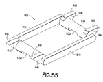
- FIGS. 54A-54C are bottom, side, and end views, respectively, of a retaining hub used in the lancet device shown in FIG. 53 ;
- FIG. 55 is a perspective view of the retaining hub shown in FIGS. 54A-54C
- FIG. 56 is a perspective view of a final embodiment of the lancet device
- FIG. 57 is a longitudinal cross-sectional view of the lancet device of FIG. 56 ;
- FIG. 58 is a transverse cross-sectional view of the lancet device of FIG. 56 taken along line 58-58 in FIG. 57 ;
- FIG. 59 is an exploded and partial cross-sectional view of the lancet device of FIG. 56 showing a rear cap, guide plate and shield of the lancet device;
- FIG. 60 is a perspective view of a lancet used in the lancet device of FIG. 56 ;
- FIG. 61 is a perspective view of a rearward portion of the lancet of FIG. 60 showing the lancet associated with the shield and guide plate shown in FIG. 59 ;
- FIG. 62 is a side view of the assembled structure shown in FIG. 61 additionally including the rear cap shown in FIG. 59 ;
- FIG. 64 is a perspective view of a forward end of the shield of the lancet device of FIG. 56 ;
- FIGS. 65A and 65B are longitudinal and transverse cross-sectional views, respectively, of the lancet device of FIG. 56 showing the lancet device in an initial, pre-actuated state;
- FIGS. 66A and 66B are longitudinal and transverse cross-sectional views, respectively, of the lancet device of FIG. 56 showing the lancet device in an initial stage of actuation;
- FIGS. 67A and 67B are longitudinal and transverse cross-sectional views, respectively, of the lancet device of FIG. 56 showing the lancet device at the point of actuation.
- the lancet device 10a generally includes a housing 12a, a shield 14a movably associated with the housing 12a, and a lancet 70a movably disposed in the housing 12a.
- shield 14a is movably associated with the housing 12a, and is at least partially disposed within housing 12a.
- the shield 14a typically extends partially outward from the housing 12a, while the lancet 70a is contained within housing 12a and is axially movable through the shield 14a.
- the housing 12a is generally in the form of an elongated body, referred to hereinafter as main body 20a.
- the main body 20a has a generally cylindrical and hollow configuration.
- the main body 20a has a distal or forward end portion 22a, and a rear cap 24a forming a proximal or rearward end portion 26a of the main body 20a.
- the interior of main body 20a is generally open and comprises an internal cavity or bore 28a.
- the internal cavity 28a is closed at the rearward end due to the presence of rear cap 24a, and includes a front opening 30a defmed by a forward end portion 22a of main body 20a, and through which shield 14a extends.
- Main body 20a and rear cap 24a may be integrally formed.
- main body 20a and rear cap 24a may be separate elements that are affixed together to form housing 12a, which facilitates assembly of lancet device 10a.
- main body 20a and rear cap 24a may be affixed together through an appropriate medical grade adhesive, or connected using inter-engaging structures providing a mechanical engagement therebetween, such as a friction-fit or a snap-fit connection.
- main body 20a may include an annular rim 32a defining an annular groove 34a
- rear cap 24a may include a mating annular rim 36a having a mating annular lip 38a as mating elements.
- annular lip 38a extends within the rear open end of main body 20a, with annular lip 38a snap-fitting over annular rim 32a and into annular groove 34a of main body 20.
- Main body 20a further comprises an internal ridge 40a, typically a perimetrically-extending ridge 40a forward of annular groove 34a, the purpose and function of which will be described herein.
- main body 20a of housing 12a may include a forward rim 42a formed as part of forward end potion 22a and which defines front opening 30a.
- shield 14a extends outward at least partially from front opening 30a in the forward end portion 22a of main body 20a.
- Shield 14a is a generally cylindrical, hollow structure comprising a shield body 50a having a distal or forward end 52a and a proximal or rearward end 54a, and defines an internal cavity or bore 56a extending therethrough.
- the forward end 52a of shield body 50a defines a partial forward end wall 58a defining a forward opening 60a, through which a puncturing element of lancet 70a extends when lancet device 10a is actuated by a user as will be discussed in more detail herein.
- the forward end wall 58a generally defines a small contact area about forward opening 60a for contacting an intended puncture area on a patient's body.
- the reduced contact area may be made smaller (i.e., reduced in surface area) by providing a plurality of peripheral indentations (not shown) formed perimetrically in shield 14a.
- the external surface features of housing 12a and shield 14a may be formed in accordance with the ergonomic features and structure disclosed in co-pending application Serial No. 11/123,849, filed November 30, 2004 , entitled “Lancet Device", and naming Bradley Wilkinson as inventor. The disclosure of the foregoing "Lancet Device” application is incorporated herein by reference thereto.
- the shield 14a is axially and slidably movable within housing 12a.
- the shield 14a and housing 12a may be coaxially associated, with the shield 14a and housing 12a coaxially disposed around a common Central Axis A.
- the shield 14a and housing 12a may each be generally cylindrically shaped.
- a shearable element 62a is further associated with shield 14a.
- shearable element 62a is disposed at the rearward end 54a of shield body 50a and engages a rear rim 63a of shield body 50a.
- Shearable element 62a comprises an annular sleeve portion 64a that extends axially in a distal direction along the outer surface of shield body 50a.
- the annular sleeve 64a receives the rearward end 54a of shield body 50a so as to be positioned between shield body 50a and main body 20a of housing 12a.
- the inner surface of annular sleeve 64a engages a proximally-extending portion of the outer surface of shield body 50a at the rearward end 54a of shield body 50a, while the outer surface of shearable element 62a slidably cooperates with the inner surface of main body 20a of housing 12a.
- Shearable element 62a further typically comprises two opposing and inward-projecting breakable shelves or wings 66a that engage lancet 70a as described further herein.
- shearable element 62a is shown with two opposing and inward-extending shelves or wings 66a, it will be appreciated that only one shelf or wing 66a is necessary for interference engagement with the lancet 70a as described herein.
- Breakable shelves or wings 66a may comprise a weakened area or score line 67a for allowing the shelves 66a to break (i.e., fail) when sufficient downward pressure is applied thereto as discussed herein.
- Breakable shelves or wings 66a are generally inwardly radially-extending cantilevers which may be made of a similar or dissimilar material compared to that chosen for shield 14a.
- Shearable element 62a is adapted to slide in combination with shield body 50a in main body 20a of housing 12a when axial motion is imparted to shield body 50a, for example by axially retracting (i.e., inserting) shield body 50a into main body 20a to actuate the lancet device 10a as described herein.
- shearable element 62a comprises an abutment recess 68a defined by sleeve portion 64a which engages the proximal or rearward end 54a of shield body 50a, and rear rim 63a in particular.
- any axial motion applied to shield body 50a to retract (i.e., insert) shield body 50a into main body 20a of housing 12a will be transmitted to shearable element 62a through the interference engagement of rear rim 63a in abutment recess 68a.
- shearable element 62a will slide within main body 20a of housing 12a along with shield body 50a when axial motion applied thereto for actuating the lancet device 10a.
- the captured portion of shield body 50a may be secured in sleeve portion 64a of shearable element 62a so that there is tight engagement between these elements and ensuring that axial motion imparted to shield body 50a will be transmitted to shearable element 62a.
- a medical grade adhesive or mechanical locking engagement may be provided between the inner surface of sleeve portion 64a and the captured portion (i.e., outer surface) of shield body 50a at the rearward end 54a of shield body 50a to ensure that these elements are secured together and move as a unit in main body 20a of housing 12a.
- Forward rim 42a of main body 20a of housing 12a is formed to provide an interference engagement with the distal end of sleeve portion 64a of shearable element 62a to prevent shearable element 62a and, consequently, shield body 50a from axially sliding completely out of housing 12a through front opening 30a.
- Lancet device 10a further comprises a lancet 70a disposed within the housing 12a, and extending into shield 14a.
- Lancet 70a includes a puncturing element shown in the form of a lancet 72a.
- Lancet 72a comprises a puncturing end 74a at the forward end thereof.
- Lancet 70a is adapted for axial movement through the internal cavity 56a of shield body 50a between an initial position, wherein the puncturing end 74a is disposed within shield body 50a to a puncturing position wherein the puncturing end 74a extends beyond the forward opening 60a of shield body 50a a sufficient distance to cause a puncture wound in a patient's body. Further details regarding the operation of lancet device 10a and lancet 70a are provided hereinafter.
- the puncturing end 74a of lancet 72a is adapted for puncturing the skin of a patient, and may be in the form of a pointed end, needle tip, blade edge, and the like. Puncturing end 74a may include a preferred alignment orientation, such as with a pointed end or a blade aligned in a specific orientation. In such an orientation, shield body 50a and/or main body 20a of housing 12a may include target indicia corresponding to the alignment orientation of puncturing end 74a. Indentations (not shown) in the shield body 50a and/or indentations (not shown) in main body 20a may function as such an alignment orientation, as described in co-pending Application Serial No. 11/123,849 , previously incorporated by reference.
- Lancet 70a further includes a carrier body 76a supporting lancet 72a at the rearward end thereof.
- the carrier body 76a and shield body 50a may include corresponding guiding surfaces for guiding the movement of lancet 70a in shield body 50a.
- carrier body 76a may include guide tabs 78a on an external surface thereof with shield body 50a defining corresponding guide channels 80a extending longitudinally along an inner surface thereof for accommodating guide tabs 78a slidably therein.
- the carrier body 76 may include a pair of guide tabs 78a on opposing lateral sides thereof as illustrated, or a single guide tab 78a, and shield body 50a may include a corresponding pair of guide channels 80a extending along opposing inner surfaces thereof corresponding to each of the guide tabs 78a, or a single corresponding guide channel 80a. It is contemplated that the arrangement of the guide tabs and channels 78a, 80a may be reversed, and multiple guide tabs-guide channels 78a, 80a (i.e., three or more) may also be used.
- the guide tabs 78a and guide channels 80a ensure that lancet 70a is properly aligned within shield body 50a, and guides the sliding axial movement of lancet 70a within shield body 50a and, further, may be used to prevent or resist rotational movement of carrier body 76a in shield body 50a.
- a distal facing surface 82a on guide tabs 78a engages shelves or wings 66a on shearable element 62a in the initial or pre-actuated state of lancet device 10a until the shelves or wings 66a are broken to release lancet 70a.
- the carrier body 76a further comprises a proximal or rearward end spring guide 86a and a distal or forward end spring guide 88a for engaging a drive spring and retraction spring, respectively, of lancet device 10a as described herein.
- Spring guides 86a, 88a may be formed integral with the carrier body 76a or be provided as distinct, separate elements and secured to the body of carrier body 76a by means customary in the medical field as, for example, with medical grade adhesive or direct mechanical attachment.
- Drive spring 92a is adapted to exert a biasing force against lancet 70a to drive lancet 70a through the lancet device 10a toward the puncturing position, and is disposed between the rearward end of the housing 12a and the lancet 70a.
- Rear cap 24a may include structure for alignment of and/or for maintaining drive spring 92a in the proper orientation on rear cap 24a.
- rear cap 24a may include an internal alignment structure (not shown) for correctly positioning the drive spring 92a.
- the lancet 70a includes proximal spring guide 86a which engages the opposite end of drive spring 92a in the initial or pre-actuated state of lancet device 10a.
- drive spring 92a extends between rear cap 24a and distal spring guide 86a of carrier body 76a.
- drive spring 92a is in a substantially unloaded, relaxed condition and exerts little to no biasing force on lancet 70a.
- the lancet device 10a Upon compressing or "loading" the drive spring 92a, the lancet device 10a is placed into an armed or loaded state ready for a puncturing procedure as described in detail herein.
- a retraction or return spring 94a may further be provided at the forward or distal end of the lancet device 10a, for retracting the lancet 70a within the shield body 50a after the lancet 70a has moved distally to the puncturing position wherein the puncturing element 74a extends outward from the distal or forward end 54a of shield body 50a a sufficient distance to cause a puncture wound in the patient.
- Retraction spring 94a is adapted to be engaged by distal spring guide 88a extending forward from carrier body 76a during the forward movement of lancet 70a, as described herein.
- the forward or distal end wall 58a of shield body 50a further comprises an axially rearward, or proximally-extending internal sleeve 96a which defines a distal end pocket 98 for receiving retraction spring 94a.
- the retraction spring 94a is disposed in distal end pocket 98a throughout the operation sequence of lancet device 10a in a puncturing procedure.
- the retraction spring 94a may be secured in distal end pocket 98a through use of a medical grade adhesive or by mechanically securing retraction spring 94a in distal end pocket 98a.
- the drive and retraction springs 92a, 94a are typically compression springs capable of storing potential energy when in a compressed state.
- Lancet device 10a may further include a protective tab or cover 100a for protectively covering the forward end of the lancet 70a and, in particular, the puncturing end 74a of lancet 72a.
- the tab or cover 100a protectively covers puncturing end 74a to maintain sterility thereof prior to use.
- the tab or cover 100a is typically a relatively thin and elongated structure that extends from carrier body 76a through the forward opening 60a in shield body 50a for grasping by a user of the lancet device 10a.
- Tab or cover 100a may be integrally formed with the body of carrier body 76a, for example, by being integrally formed with carrier body 76a during a plastic molding process.
- connection between tab or cover 100a and carrier body 76a may include a weakened area in the form of a perimeter groove or score line, along which the tab or cover 100a is intended to break to remove the cover 100a from carrier body 76a.
- the tab or cover 100a as depicted, extends forward from distal spring guide 88a of carrier body 76a.
- Tab or cover 100a is sized to extend axially through retraction spring 94a.
- Various configurations of the tab or cover 100a are described in co-pending Application Serial No. 11/123,849 , previously incorporated by reference.
- the respective elements of the lancet device 10a are all typically formed of molded plastic material, such as a medical grade plastic material.
- the lancet 72a may be constructed of any suitable material adapted for puncturing the skin, and is typically a surgical grade metal such as stainless steel.
- Lancet device 10a is typically initially provided with cover 100a extending distally from carrier body 76a, and through forward opening 60a in the forward end wall 58a of shield body 50a.
- the drive spring 92a is substantially uncompressed (i.e., unloaded) and in a relaxed state.
- Drive spring 92a extends from the inner side of rear cap 24a to the carrier body 76a and, more particularly, is disposed about proximal spring guide 86a of carrier body 76a.
- the drive spring 92a To use the lancet device 10a in a puncturing procedure, the drive spring 92a must be compressed and placed into a compressed, armed state to provide the biasing force needed to move the lancet 70a through housing 12a and shield 14a. Further, in the initial state, the drive spring 92a acts on spring guide 86a substantially only to position lancet 70a within main body 20a of housing 12a. More particularly, drive spring 92a positions carrier body 76a at a relatively fixed and stationary position within main body 20a of housing 12a, wherein the lancet 70a occupies a generally fixed position relative to main body 20a of housing 12a and shield body 50a of shield 14a.
- drive spring 92a acting on spring guide 86a of carrier body 76a positions the carrier body 76a such that guide tabs 78a extending laterally from carrier body 76a contact cantilevered shelves or wings 66a on shearable element 62a, which further serves to position shearable element 62a and shield body 50a at a substantially fixed position relative to main body 20a.
- the drive spring 92a acts on carrier body 76a to position carrier body 76a such that the distal surface 82a on guide tabs 86a is in interference engagement with shelves 66a, and positions the shearable element 62a and shield body 50a at a generally fixed position relative to main body 20a. Accordingly, until the user is ready to use the lancet device 10a, shearable element 62a and shield body 50a are kept at a substantially constant relative position with respect to main body 20a.
- cover 100a is removed typically by moving cover 100a in a combined twisting and pulling motion in forward opening 60a defined in forward end wall 58a of shield body 50a to break the frangible connection with carrier body 76a. Once the frangible connection is broken, the cover 100a may be removed through the forward opening 60a. The forward end wall 58a of shield body 50a may then be placed in contact with a location on the patient's body where it is desired to cause a puncture injury to initiate blood flow. If provided, target indicia may be aligned with the desired location of puncture.
- the user exerts a downwardly directed force on main body 20a of housing 12a forcing shield body 50a of shield 14a to retract (i.e., depress) into housing 12a.
- the user applies a downward directed force in the direction of Arrow X, thereby applying a force against the user's body (i.e., skin surface).
- Such force establishes an opposing force on forward end wall 58a of shield body 50a causing shield body 50a to retract axially and proximally within main body 20a of housing 12a.
- rearward end 54a of shield body 50a moves proximally (i.e., rearward) toward rear cap 24a.
- drive spring 92a substantially reaches its maximum compression between proximal spring guide 86a and rear cap 24a and the lancet device 10a is now "armed” or “loaded” sufficiently to carry out a puncturing procedure.
- spring guide 86a does not need to contact or “bottom out” against the inner side of rear cap 24a, and drive spring 92a may have sufficient stored potential energy to carry out the actuation of lancet device 10a.
- proximal spring guide 86a contacts the inner side of rear cap 24a, continued downward force applied to main body 20a of housing 12a is applied entirely to breakable shelves or wings 66a through the interference engagement with guide tabs 78a.
- the user's entire downward applied force is transmitted from main body 20a (i.e., rear cap 24a ) to carrier body 76a and, accordingly, guide tabs 78a.
- the interference engagement between guide tabs 78a and shelves 66a focuses the downward applied force on the shelves 66a, which will cause the shelves 66a to yield, shear, or break (i.e., fail) in a distal or forward direction at weakened area 67a and into internal cavity 56a of shield body 50a.
- the restraining or compression force previously applied to drive spring 92a due to the interference engagement between guide tabs 78a and shelves 66a is released, releasing the stored potential energy in drive spring 92a to allow the drive spring 92a to move lancet 70a forward in shield body 50a.
- the shearable element 62a and shield body 50a are free to retract rearward to engage annular rim 36a on rear cap 24a where their further rearward movement thereof is halted.
- shearable element 62a and shield body 50a move toward annular rim 36a, shearable element 62a rides over top of annular ridge 40a on the inner surface of main body 20a of housing 12a.
- the engagement of shearable element 62a with annular ridge 40a increases the frictional engagement between the shearable element 62a and main body 20a of housing 12a, thereby substantially fixing the position of shearable element 62a and shield body 50a relative to main body 20a and inhibiting the shield body 50a from moving forward again in main body 20a.
- the frictional engagement between the outer surface of shearable element 62a and annular ridge 40a operates substantially as a frictional lock or brake to substantially prevent forward movement of shield body 50a in main body 20a after the shearable element 62a and shield body 50a retract fully into main body 20a and engage rear cap 24a.
- the drive spring 92a biases the lancet 70a away from rear cap 24a and through internal cavity 56a in shield body 50a.
- the biasing force of drive spring 92a propels lancet 70a downward and distally away from the rear cap 24a axially through main body 20a of housing 12a and shield body 50a of shield 14a.
- corresponding guide tabs 78a and guide channels 80a guide lancet 70a axially through shield body 50a.
- the biasing force acting on lancet 70a is preferably sufficient to cause the puncturing end 74a of lancet 72a to project a sufficient distance and with sufficient kinetic energy from the forward opening 60a in shield body 50a to cause a puncture wound in the desired location on a patient's body. Moreover, during the propelling movement of lancet 70a, proximal spring guide 86a on carrier body 76a of lancet 70a releases from drive spring 92a which remains connected to rear cap 24a.
- distal spring guide 88a engages the rearward end of retraction spring 94a.
- the biasing force provided by drive spring 92a is at least in part applied to retraction spring 94a by engagement of distal spring guide 88a with the rearward end of retraction spring 94a which causes the retraction spring 94a to compress toward distal end pocket 98a.
- the retraction spring 94a is designed such that it may be compressed in whole or in part by the biasing force of drive spring 92a propelling lancet 70a, but still permits puncturing end 74a of lancet 72a to extend through forward opening 60a in shield body 50a a sufficient distance and with sufficient force to puncture the skin of the patient and initiate blood flow.
- Distal spring guide 88a is sized to provide an abutment surface for abutting against internal sleeve 96a supporting retraction spring 94a to prevent lancet 70a from axial movement entirely out of shield body 50a through forward or front opening 60a.
- retraction spring 94a is typically a compression spring and will have sufficient resilience to return to a relaxed, unloaded state within shield body 50a after the lancet 70a extends to the puncturing position. Accordingly, once the retraction spring 94a is compressed it will provide a return biasing force on the lancet 70a by engagement with the distal spring guide 88a on carrier body 76a. The retraction spring 94a thereby acts between the forward end wall 58a of the shield body 50a and distal spring guide 88a on carrier body 76a to cause sufficient or complete retraction of the lancet 70a into shield body 50a.
- retraction spring 94a applies a return biasing force that retracts the puncturing end 74a of lancet 72a entirely within shield body 50a. Moreover, as the retraction spring 94a returns to a relaxed or unloaded state within shield body 50a, the lancet 70a is returned to a static position within shield body 50a, wherein lancet 70a is disposed at a relatively fixed and stationary position within shield body 50a. Once retraction spring 94a returns to a relaxed or uncompressed state, the retraction spring 94a maintains the lancet 70a disposed within the shield body 50a with puncturing end 74a shielded within shield body 50a, and preventing further movement of lancet 70a to the puncturing position. The lancet device 10a is therefore safely protected from re-use and may be properly discarded, such as in an appropriate medical waste container.
- lancet device 10b comprises the same basic components as lancet device 10a described previously.
- lancet device 10b comprises a housing 12b, a shield 14b movably associated with the housing 12b, and a lancet 70b movably disposed in housing 12a and movable through shield 14b.
- the foregoing basic components of lancet device 10b are substantially similar to the corresponding components of lancet device 10a, only distinct differences between these components will be discussed herein, along with the use and sequence of operation of lancet device 10b.
- lancet device 10b does not comprise a structure corresponding to shearable element 62a discussed previously.
- Lancet device 10b comprises the shield 14a having a shield body 50b with a rear ledge or rim 102 at shield proximal end 54b.
- the rear ledge or rim 102 is adapted for interference engagement with forward rim 42b at the forward end portion 22b of main body 20a of housing 12a.
- the interference engagement of rear ledge 102 with forward rim 42b is provided to prevent the shield body 50b from axially sliding completely out of housing 12b through front opening 30b defined in forward rim 42b prior to actuating lancet device 10b.
- Rear rim 102 is sized such that it may contact and slidably engage the inner surface of main body 20b when shield body 50b is retracted (i.e., depressed) into main body 20b, as will occur when the lancet device 10b is actuated by a user.
- shield body 50b comprises inward-extending shelves, wings, or internal tabs 104, which take the place of breakable shelves or wings 66a on shearable element 62a in lancet device 10a.
- the internal tabs 104 are desirably formed integrally with the shield body 50b, but may also be part of an additional, separate structure associated with shield body 62a, for example associated with rear rim 102 and extending into central cavity or bore 56b of shield body 50b.
- shield body 50b is shown with two opposing and inward-extending internal tabs 104, it will be appreciated that only one internal tab 104 is necessary for engagement with the lancet 70b in a similar manner to that described previously in connection with the breakable shelves or wings 66a on shearable element 62a.
- guide tabs 78a form the structure on lancet 70a for an interference engagement with breakable shelves or wings 66a, which initially just contact shelves 66a under the position effect of drive spring 92a in the initial or pre-actuated state of lancet device 10a.
- guide tabs 78b are further provided or formed with cutting elements 106 which may be cutting blades, edges, and the like. Cutting elements 106 may be formed integrally with guide tabs 78b or, alternatively, be separate cutting structures secured to guide tabs 78b by means customary in the medical device field, such as direct mechanical or adhesive attachment.
- lancet device 10b is substantially similar in all other respects to the structure of lancet device 10a described previously.
- lancet device 10b Prior to use, cover 100b extending distally from carrier body 76b is removed by breaking the frangible connection with carrier body 76b in the manner described previously and withdrawing cover 100b from forward opening 60b in forward end wall 58b of shield body 50b. The forward end wall 58b of shield body 50b may then be placed in contact with a target location on a patient's body.
- the drive spring 92b In the initial state of lancet device 10b, the drive spring 92b is substantially uncompressed (i.e., unloaded) and in a relaxed state. Drive spring 92b extends from proximal spring guide 86a of carrier body 76a to rear cap 24b.
- drive spring 92a is in a relaxed condition and acts on spring guide 86b substantially to position lancet 70b at a stationary position within main body 20b of housing 12a, wherein the lancet 70b occupies a generally fixed position relative to main body 20b.
- drive spring 92b acts on spring guide 86b on carrier body 76b to position carrier body 70a in main body 20b such that guide tabs 78b and more particularly, cutting elements 106 are in interference engagement with tabs or shelves 104 in the internal cavity 56b of shield body 50b.
- the interference engagement between cutting elements 106 and internal tabs 104 further operates to place shield body 50b at a generally fixed and stationary position relative to main body 20b. Accordingly, until the user is ready to use lancet device 10b, shield body 50b is kept substantially at a generally fixed and stationary position relative to main body 20a by virtue of the interference engagement between guide tabs 78b and internal tabs 104 in shield body 50b.
- the user grasps opposing sides of housing 12b and exerts downwardly directed force on main body 20. This force causes an opposing force on forward end wall 58b of shield body 50b, causing shield body 50b to retract axially within main body 20a. As shield body 50b retracts into main body 20b, rearward end 54a of shield body 50a moves proximally (i.e., rearward) toward rear cap 24b. Due to the interference engagement between guide tabs 78b and internal tabs or shelves 104 and, more particularly, between cutting elements 106 on guide tabs 78b and internal tabs or shelves 104, lancet 70b also moves rearwardly toward rear cap 24b.
- proximal spring guide 86b contacts rear cap 24b, the downward force applied to main body 20b of housing 12b is applied entirely to the interference engagement between cutting elements 106 and internal tabs 104.
- main body 20b i.e., rear cap 24b
- guide tabs 78b and cutting elements 106 the user's entire downward applied force is transmitted from main body 20b (i.e., rear cap 24b) to carrier body 76b and, accordingly, guide tabs 78b and cutting elements 106.
- the downward cutting force on the internal tabs 104 is now sufficient to cut-through or plastically deform internal tabs 104.
- shield body 50b is able to retract further rearward under the downward force still typically applied by the user to housing 12b.
- the shield body 50b ultimately moves rearward to a position engaging annular rim 36b on rear cap 24b where further rearward movement is halted.
- rear rim 102 on the rearward end 54b of shield body 50b rides over top of annular ridge 40b.
- the annular ridge 40b thereafter forms a locking structure to inhibit or prevent subsequent forward movement of shield 50b.
- the drive spring 92b biases lancet 70b away from rear cap 24b and through shield body 50b.
- the corresponding guide tabs 78b and guide channels 80b guide lancet 70b axially through shield body 50b.
- the biasing force applied to lancet 70a is preferably sufficient to cause the puncturing end 74b of lancet 72b to project a sufficient distance and with sufficient force from the forward opening 60b in shield body 50b to cause a puncture wound at the target location on the patient's body.
- proximal spring guide 86b on carrier body 76b releases from drive spring 92b which remains connected to rear cap 24b.
- Internal sleeve 96b at the forward end wall 58b defines a distal stop for engaging distal spring guide 88b and prevents lancet 70b from axial movement entirely out of shield body 50b through forward opening 60b.
- distal spring guide 88b engages retraction spring 94b.
- the biasing force applied to lancet 70b by drive spring 92b is at least in part applied to retraction spring 94b by engagement of distal spring guide 88b with retraction spring 94b, which causes the retraction spring 94b to compress toward distal end pocket 98b.
- the retraction spring 94a permits puncturing end 74b of lancet 72b to extend through forward opening 60b in shield body 50b a sufficient distance and with sufficient kinetic energy to puncture the skin of the patient and initiate blood flow, and thereafter return lancet 70b to a substantially fixed and stationary position within shield 14b.
- the lancet 70a is retracted in shield 14b and returned to a substantially fixed and stationary positioned within shield body 14b. Thereafter, the engagement of retraction spring 94b with distal spring guide 88b maintains the lancet 70b at a generally fixed and stationary position within shield body 50b. This maintains puncturing end 74b shielded within shield body 50b, and prevents further movement of lancet 70b to the puncturing position.
- lancet device 10c comprises the same basic components as lancet devices 10a, 10b described previously.
- lancet device 10c comprises a housing 12c, a shield 14c movably associated with the housing 12c, and a lancet 70c movably disposed in housing 12c.
- the foregoing basic components of lancet device 10c are substantially similar to the corresponding components of lancet devices 10a, 10b only distinct differences between these components will be discussed herein, along with the general use and sequence of operation of lancet device 10c.
- lancets 70a, 70b are initially positioned at substantially fixed and stationary positions in housings 12a, 12b by drive springs 92a, 92b in the initial, pre-actuated states of these devices.
- drive springs 92a, 92b are initially in a relaxed, unloaded condition and act upon lancets 70a, 70b to position lancets 70a, 70b relative to housings 12a, 12b.
- Lancet devices 10a, 10b are only placed in an armed or loaded state when shields 14a, 14b are retracted (i.e., depressed) into housings 12a, 12b under the force applied by a user, which in turn causes lancets 70a, 70b to act upon drive springs 92a, 92b and compress and load the respective drive springs 92a, 92b with potential energy.
- Lancet device 10c is initially provided in an armed or loaded state, with lancet 70c ready to be biased to a puncturing position by a compressed drive spring 92c.
- drive spring 92c is in a compressed (i.e., loaded) state, ready to bias the lancet 70c through a puncturing procedure upon release.
- lancet device 10c is provided with drive spring 92c compressed between proximal spring guide 86c on carrier body 76c and rear cap 24c.
- the lancet 70c is secured against forward movement into shield 14c by a locking or actuation structure 110 extending between housing 12c and lancet 70c. Actuator 110 prevents release of lancet 70c and, correspondingly, maintains compression of drive spring 92c until a user of the lancet device 10c is ready to carry out a puncturing procedure.
- Actuator 110 generally comprises a sleeve portion 112 and one or more pivotal splints or tabs 114, for example elastic splints, extending from the sleeve portion 112.
- Sleeve portion 112 is disposed in an annular wall recess 116 defined in the inner surface of main body 20c of housing 12c.
- Main body 20c is formed with a generally thicker annular wall in lancet device 10c in comparison to lancet devices 10a, 10b.
- Sleeve portion 112 may be secured in wall recess 116 by a medical grade adhesive and/or preferably by being captured axially between wall recess 116 and annular rim 36c on rear cap 24c and thereby frictionally held in wall recess 116.
- Actuator 110 is depicted with two generally inward-extending splints or tabs 114 engaging lancet 70c. While this configuration is desirable, only one elastic splint 114 for engaging lancet 70c is typically required, and additional splints 114 in excess of two may be also be provided.
- the splints 114 extend generally rearward or in a proximal direction in main body 20c and engage guide tabs 78c on carrier body 76c of lancet 70c. Splints 114 are angled inward, in this instance, at approximately a 45° angle relative to Central Axis A to engage guide tabs 76c in the initial state of lancet device 10c. In particular, ends 118 of splints 114 engage guide tabs 78c on carrier body 76c to prevent lancet 70c from releasing from the initial, armed state of lancet device 10c and thereby maintain drive spring 92c in a compressed state until lancet device 10c is actuated by a user.
- Splints 114 are each connected by a hinge connection 120 to sleeve portion 112.
- the hinge connection 120 may be a living hinge as illustrated as an exemplary embodiment of this structure. Ends 118 of splints 114 engage a corner of guide tabs 78c, such that distal movement of carrier body 76c distally with respect to housing 12c in absence of shield 14c would cause splints 114 to generally compress between hinge connection 120 and the point of contact between guide tabs 78c.
- lancet device 10c is actuated when a user depresses housing 12c to retract (i.e., depress) shield 14c therein.
- shield 14c is now adapted to release actuator 110 between housing 12c and lancet 70c, thereby releasing compressed drive spring 92c to bias the lancet 70c through a puncturing procedure.
- shield 14c is adapted to engage and release actuator 110.
- shield body 50c may be formed with a tapered rear rim 122 at shield proximal end 54c.
- the tapered rear rim 120 is generally tapered in the same direction as splints 114 to engage the distal or forward facing sides of splints 114.
- the point of engagement for the tapered rear rim 122 is on splints 114 at a location between hinge connection 120 and the point of contact between guide tabs 78c.
- the tapered rear rim 122 may define a taper of about 45° to correspond to the inward taper of splints 114.
- the tapered rear rim 122 is in contact with splints 114 so that any rearward movement of shield 14c into housing 12a will immediately act upon the actuator 110 and splints 114 in particular. While the rear rim 122 is illustrated with a defined taper, it will be appreciated that such taper may be omitted and shield body 50c formed as a cylindrical structure with a flat or blunted rear rim 122.
- lancet device 10c extending distally from carrier body 76c is first removed by breaking the frangible connection with carrier body 76c and withdrawing cover 100c from forward opening 60c in forward end wall 58c of shield body 50c. The forward end wall 58c of shield body 50c may then be placed in contact with the target location on the patient's body.
- lancet device 10c is initially provided in an armed state with lancet 70c ready to initiate a puncturing procedure when compressed drive spring 92c is released.
- shield body 50c To carry out a puncturing procedure, the user grasps opposing sides of housing 12c and exerts downwardly directed force in the direction of Arrow X on main body 20c forcing shield body 50c to retract into main body 20c. This force causes an opposing force on forward end wall 58c of shield body 50c, causing shield body 50c to retract axially within main body 20c. As shield body 50c retracts into main body 20c, tapered rear rim 122 on rearward end 54c of shield body 50c and in engagement with splints 114 begins to move splints 114 radially outward toward sleeve portion 112.
- shield body 50c continues their radial outward movement away from lancet 70c until the splints 114 disengage from guide tabs 78c and release the interference engagement therewith.
- the configuration of actuator 110 converts the axial movement of shield body 50c into pivotal radial outward movement of splints 114 to effectuate actuation of lancet device 10c
- drive spring 92c biases the lancet 70c away from rear cap 24c and through shield body 5cb.
- corresponding guide tabs 78c on carrier body 76c and guide channels 80c within shield body 50c guide lancet 70c axially through shield body 50c.
- the biasing force imparted to lancet 70c is preferably sufficient to cause the puncturing end 74c of lancet 72c to project a sufficient distance and with sufficient force from the forward opening 60c of shield body 50c to cause a puncture wound in the desired location on the patient's body.
- proximal spring guide 86c on carrier body 76c releases from drive spring 92c which remains connected to rear cap 24c.
- Distal spring guide 88c provides an abutment surface for engaging internal sleeve 96c supporting retraction spring 94c to prevent lancet 70c from axial movement entirely out of shield body 50c through forward opening 60c.
- distal spring guide 88c engages retraction spring 94c.
- the biasing/propelling force provided by drive spring 92c is at least in part applied to retraction spring 94c by engagement of distal spring guide 88c with retraction spring 94c, which causes the retraction spring 94c to compress toward distal end pocket 98c.
- the retraction spring 94c permits puncturing end 74c of lancet 72c to extend through forward opening 60c in shield body 50c a sufficient distance and with sufficient force to puncture the skin of the patient and initiate blood flow, and thereafter return lancet 70c to a substantially fixed and stationary position within shield 14b.
- the lancet 70c is retracted in shield 14c and returned to a generally stationary and fixed position within shield body 50c. Thereafter, the engagement of retraction spring 94c with distal spring guide 88c maintains the lancet 70c at a stationary and relatively fixed position within shield body 50c and maintains puncturing end 74c shielded within shield body 50c preventing further movement of lancet 70c to the puncturing position.
- a fourth embodiment of a lancet device 10d is generally illustrated, and generally comprises a housing 12d and a lancet 70d disposed in housing 12d.
- Lancet device 10d differs from lancet devices 10a-c discussed previously, as lancet device 10d is not actuated through the retraction (i.e., depression) of a shield element into housing 12d.
- lancet device 10d is similar to lancet device 10c discussed immediately above because lancet device 10d is initially provided in an armed or loaded state, with lancet 70d ready to be biased to the puncturing position by drive spring 92d upon release of an interfering structure.
- drive spring 92d In this initial, armed state, drive spring 92d is in a compressed (i.e., loaded) state, ready to bias the lancet 70d through a puncturing procedure upon repositioning lancet 70d with respect to an interfering structure or engagement between housing 12d and lancet 70d.
- the configuration of the housing 12d, lancet 70d, and drive spring 92d differ from previous embodiments and these differences will now be described.
- Housing 12d of lancet device 10d comprises an elongated main body 20d that generally defines a cylindrical and hollow configuration.
- the main body 20d has a distal or forward end portion 22d, and a rear cap 24d forming a proximal or rearward end portion 26d of the main body 20d.
- the interior of housing 12d is generally open and comprises an internal cavity 28d.
- the internal cavity 28d is closed at the rearward end due to rear cap 24d, and includes a front opening 30d defined in forward end portion 22d of main body 20d, and through which lancet 70d at least partially extends when lancet device 10d is actuated.
- Main body 20d and rear cap 24d may be integrally fonned.
- main body 20d and rear cap 24d are separate elements that are affixed together to form housing 12d, as illustrated, which facilitates assembly of lancet device 10d.
- main body 20d and rear cap 24d may be affixed together through an appropriate medical grade adhesive, and/or may be connected using inter-engaging structures providing a mechanical engagement therebetween, such as a friction-fit or a snap-fit construction.
- main body 20d may include an annular rim 32d defining an annular groove 34d
- the rear cap 24a may include a mating annular rim 36d having a mating annular lip 38d as mating elements in much the same manner as described previously.
- distal or forward end portion 22d of main body 20d comprises an axially rearward-extending internal sleeve 98d that defines a distal end pocket 98d for receiving and supporting retraction spring 94d.
- the retraction spring(s) were disposed in a distal end pocket formed as part of the forward end wall of the actuating shield structure.
- This structure is now provided at the forward end portion 22d of main body 20d of housing 12d.
- main body 20d of housing 12d further comprises an actuation structure or actuator 130 for causing actuation of lancet 70d and corresponding release of drive spring 92d.
- Actuator 130 generally comprises an actuating button or lever 132 that is typically pivotally associated with main body 20d.
- the pivotal association with main body 20d may be in the form of a living hinge or equivalent structure and lever 132 may thus be integrally formed with main body 20d.
- a tab member 134 depends from an inner side of actuating lever 132 for engaging lancet 70d and causing actuation of the same.
- lever 132 is pivotally connected to main body 20d so that the lever 132 may be depressed inward into internal cavity 28d in main body 20d, such that tab member 134 interacts with lancet 70d to cause actuation or release of lancet 70d.
- Main body 20d of housing 12d includes opposing inner sidewalls 136 each defining an internal guide channel 138 for guiding movement of lancet 70d within main body 20d.
- Guide channels 138 may be formed as grooves or recesses in the inner sidewalls 136, or be formed in a structure extending inward from the respective sidewalls 136.
- Guide channels 138 are generally L-shaped and comprise a longitudinally extending main channel 140 and a generally transversely extending side channel 142.
- Main channel 140 extends distally forward from an area proximate to tab member 134 to a location proximate to retraction spring 94d.
- Main channel 140 defines an abutment surface or stop 144 in guide channels 138 to provide a stop for carrier body 76d of lancet 70d to prevent axial movement of the lancet 70d entirely out of main body 20d through front opening 30d.
- Side channel 142 is contiguous with main channel 140 and extends approximately oblique to transverse to main channel 140. Side channel 142 extends upward in a direction towards lever 132. While side channel 142 is formed generally oblique to main channel 140, side channel 142 and main channel 140 define a tapered corner or vertex 146 at their intersection. The corner 146 defines an angle of less than about 90°.
- the opposing side channels 142 in main body 20d are used to initially receive guide tabs 78d on carrier body 76d for maintaining carrier body 76d in a dynamically stable and balanced position, thereby opposing the force acting on guide tabs 78d by drive spring 92d, and restraining compressed drive spring 92d.
- Corner 146 is used to define the transition between main channel 140 and side channel 142. Movement of guide tabs 78d towards side channels 142 allows carrier body 76d to transition from a position of dynamic stability to a position of dynamic instability. Accordingly, side channels 142 initially maintain the positioning of guide tabs 78d, with guide tabs 78d in interference engagement with corners or vertexes 146 to maintain the positioning of guide tabs 78d until lancet device 10d is to be actuated.
- Lancet 70d is formed in a generally analogous manner as previous embodiments and comprises a lancet 72d with a puncturing end 74d at the forward end thereof, and a carrier body 76d supporting lancet 72d at the rearward end thereof.
- the carrier body 76d comprises a pair of guide tabs 78d on an external surface thereof that engage guide channels 138.
- Lancet 70d is adapted for axial movement through the internal cavity 28d of main body 20d between an initial position wherein guide tabs 78d are disposed in side channels 142 and the puncturing end 74a is disposed entirely within main body 20d, to a puncturing position wherein the puncturing end 74d extends beyond the front opening 30d in main body 20d a sufficient distance to cause a puncture wound on a patient's body while guide tabs 78d remain disposed in main channels 140. Further details regarding the operation of lancet device 10d and the movement of lancet 70d are provided hereinafter.
- Carrier body 76d further comprises a proximal or rear rim 148 at the rearward end thereof.
- Rim 148 defines the forward end of proximal spring guide 86d and typically has a diameter larger than the diameter of distal spring guide 88d of carrier body 76d.
- Rim 148 is provided as a contact structure or surface on lancet 70d for engagement by tab member 134 to cause actuation of lancet device 10d.
- the diameter of rim 148 is also typically sized to be at least equal to the diameter of drive spring 92d and provides a contact structure or surface that restrains compressed drive spring 92d in the initial state of lancet 70d.
- carrier body 76d additionally comprises two opposing posts 150 cooperating with guide channels 138, and main channels 140 in particular. Posts 150 engaged in guide channels 138 permit at least a limited amount of pivotal movement by carrier body 76d about an axis passing through posts 150, and maintain lancet 70d associated with guide channels 138 until guide tabs 78d align with main channels 140 during the actuation sequence of lancet device 10d.
- drive spring 92d In the initial state of lancet device 10d, drive spring 92d is at least partially compressed between rear rim 148 on carrier body 76d and rear cap 24d, and typically has sufficient stored potential energy to conduct a skin-puncturing procedure.
- the rearward or proximal end of drive spring 92d is typically secured to rear cap 24d in the manner discussed previously in this disclosure.
- the forward or distal end of drive spring 92d is associated with carrier body 76d and may be secured to rear rim 148 by similar means discussed previously, as by suitable adhesive or direct mechanical attachment.
- Drive spring 92d generally defines an off-axis or off-center spring arrangement, wherein drive spring 92d extends at upward angle toward lever 132.
- Drive spring 92d is stabilized in the off-center and compressed (i.e., loaded) arrangement by engagement of guide tabs 78d in side channels 142 of guide channels 138.
- Corners 146 define an interfering engagement and point of transition for guide tabs 78d to maintain drive spring 92d in a compressed (i.e., loaded) state and in the off-center configuration.
- the acute angle defined by corner 146 defines a receiving notch 152 for guide tabs 78d to prevent guide tabs 78d from readily releasing from side channels 142 until intended actuation by a user.
- engagement of guide tabs 78d in guide channels 138 forms an interfering structure to secure lancet 70d against forward movement in main body 20d and, correspondingly, maintains compression of drive spring 92d until a user of the lancet device 10d is ready to carry out a puncturing operation.
- lancet device 10d As with previous embodiments, a cover (not shown) extending distally from carrier body 76d may be provided with carrier body 76d. As with previous embodiments, such a cover is removed by breaking the frangible connection with carrier body 76d and withdrawing the cover from front opening 30d in main body 20d. The forward end rim 42d of main body 20d may then be placed in contact with the target location on a patient's body. As indicated previously, lancet device 10d is initially provided in an armed state with lancet 70d ready initiate a puncturing procedure when compressed drive spring 92d is released.
- lever 132 pivotally connected to main body 20d, causing lever 132 to depress into internal cavity 28d of main body 20d.
- tab member 134 interacts with rear rim 148 on carrier body 76d.
- the downward force applied to lever 132 causes tab member 134 to move rear rim 148 downward in the internal cavity 28d.
- the carrier body 76d will substantially simultaneously pivot about posts 150 in main channel 140 of guide channels 138.
- guide tabs 78d received in side channels 142 slide downward in side channels 142 until passing corners 146 which has the effect of moving carrier body 76d from a first state of being dynamically balanced to a second state of being dynamically unbalanced, thereby allowing drive spring 92d to propel carrier body 76d through main body 20d until the puncturing end 74d of lancet 72d projects through front opening 30d in main body 20d.
- the downward movement of guide tabs 78d in side channels 142 has the optional effect of further compressing drive spring 92d.
- guide tabs 78d eventually clear corners 146 and disengage from side channels 142. At this point, guide tabs 78d align with main channel 140 of guide channels 138 and are free to move forward therein under the biasing force of drive spring 92d.
- the drive spring 92d is free to bias lancet 70d to the puncturing position. With the stored potential energy in drive spring 92d released, drive spring 92d thereafter biases the lancet 70d away from rear cap 24d and through main body 20d.
- the engagement of guide tabs 78d in guide channels 138 guides lancet 70d axially through main body 20d.
- the distal biasing energy imparted to lancet 70d is preferably sufficient to cause the puncturing end 74d of lancet 72d to project a sufficient distance and with sufficient force from the front opening 30d in main body 20d to cause a puncture wound in the desired location on the patient's body.
- proximal spring guide 86d on carrier body 76d releases from drive spring 92d which remains connected to rear cap 24d.
- the engagement of posts 150 with stops 144 in guide channels 138 prevents lancet 70d from axial movement entirely out of main body 20d through front opening 30d.
- distal spring guide 88d engages retraction spring 94d.
- the biasing force of drive spring 92d is at least in part applied to retraction spring 94d by engagement of distal spring guide 88d with retraction spring 94d, which causes the retraction spring 94d to compress toward distal end pocket 98d.
- the retraction spring 94d permits puncturing end 74d of lancet 72d to extend through front opening 30d in main body 20d a sufficient distance and with sufficient force to puncture the skin of the patient and initiate blood flow, and thereafter return lancet 70d to a generally fixed and stationary position within housing 12d.
- the lancet 70d is retracted in main body 20d and returned to a generally fixed and stationary position within main body 20d. Thereafter, the engagement of retraction spring 94d with distal spring guide 88d maintains the positioning of lancet 70d within main body 20d with puncturing end 74d of lancet 72d shielded within housing 12d, and prevents further movement of lancet 70d to the puncturing position.
- lancet device 10e comprises the same basic components or elements as lancet devices 10a-c described previously.
- lancet device 10e comprises a housing 12e, a shield 14e movably associated with the housing 12e, and a lancet 70e movably disposed in housing 12e.
- the basic components of lancet device 10e are substantially similar to the corresponding components of lancet devices 10a-c discussed previously, only distinct differences between these general components will be discussed herein, along with the use and sequence of operation of lancet device 10e.
- lancet device 10e generally follows the sequence of operation of lancet devices 10a-c, wherein lancet device 10e is armed and actuated through the retraction (i.e., depression) of shield 14e into housing 12e.
- lancet device 10e arming and actuation of lancet device 10e occurs as a result of proximal or rearward end 54e of shield body 50e of shield 14e engaging a structure within housing 12e that causes compression (i.e., loading) of drive spring 92e and, upon release of such compression, drive spring 92e biases lancet 70e through a propelling movement resulting in puncturing end 74e of lancet 72e projecting from shield 14e for puncturing procedure the skin of a patient, as discussed in more detail herein.
- compression i.e., loading
- shield 14e comprises a shield body 50e with a rear ledge or rim 162 at shield proximal end 54e.
- the rear ledge or rim 162 is generally adapted for contact or engagement with a slide plate 164 disposed in housing 12e to cause actuation of lancet device 10e as described in detail herein.
- Slide plate 164 forms the structure for compressing drive spring 92e alluded to previously.
- Rear ledge or rim 162 is also adapted to engage forward rim 42e of main body 20e of housing 12e to prevent shield body 50e from axially sliding completely out of housing 12e through front opening 30e defined in the forward end wall 58e of shield body 50e.
- Rear rim 162 is sized such that it may slide along the inner surface of main body 20b when shield body 50e is retracted (i.e., depressed) into main body 20e, as will occur when the lancet device 10b is actuated by a user.
- Slide plate 164 forms the internal structure in main body 20e of housing 12e which is used to cause compression of drive spring 92e thereby storing potential energy in drive spring 92e which, upon release, is used to bias lancet 70e to the puncturing position.
- Slide plate 164 is disposed in main body 20e of housing 12e to be in contact with rear rim 162 of shield body 50e.
- Slide plate 164 is associated with rear rim 162 of shield body 50e so that slide plate 164 may move rearward with shield body 50e as shield body 50e is retracted (i.e., depressed) into main body 20e of housing 12e to arm and actuate lancet device 10e.
- Slide plate 164 defines a generally centrally-located keyhole or key opening 166 that is sized and shaped to generally conform to the transverse cross-sectional shape of carrier body 76e of lancet 70e, to allow the cross-section of carrier body 76e to pass therethrough during actuation of lancet device 10e.
- keyhole 166 comprises a central, typically circular-shaped portion 168 and two contiguous laterally-extending notches 170, which define a shape that permits the transverse cross-section of carrier body 76e to pass therethrough during actuation of lancet device 10e, as discussed further herein.
- rear cap 24e comprises an annular rim 36e that engages an annular rear rim 32e of main body 20e of housing 12e.
- annular lip 38e on annular rim 36e engages annular groove 34e defined in annular rim 32e to join rear cap 24e to main body 20e.
- annular rim 36e is elongated and extends distally a greater distance into main body 20e of housing 12e, so as to be positioned proximate to the rear rim 162 of shield body 50e in the initial state of lancet device 10e.
- Annular rim 36e defines a tapered internal cam surface 172, which is shaped to impart a specific cam motion to slide plate 164 due to contact therewith and ultimately cause arming and actuation of lancet device 10e as described hereinafter.
- drive spring 92e is associated with lancet 70e, with the drive spring 92e extending from the inner side of rear cap 24e to carrier body 76e.
- carrier body 76e is further formed with a proximal or rear rim 174 at the rearward end thereof.
- Rim 174 generally defines the forward end of proximal spring guide 86e and typically has a diameter larger than the diameter of distal spring guide 88e and typically at least equal to the diameter of the forward end of drive spring 92e.
- Rim 174 defines a contact structure or surface on carrier body 76e that is used to compress drive spring 92e to place the lancet device 10e into a loaded or armed state.
- lancet device 10e Prior to use, cover 100e extending distally from carrier body 76e is removed by breaking the frangible connection with carrier body 76e, and withdrawing cover 100e from forward opening 60e in forward end wall 58e of shield body 50e in the manner described previously. The forward end wall 58e of shield body 50e may then be placed in contact with a target location on a patient's body. In the initial, unarmed state of lancet device 10e, the drive spring 92e is substantially uncompressed (i.e., unloaded) and extends from rear rim 174 on carrier body 76e to rear cap 24e.
- drive spring 92e In the initial, unarmed state of lancet device 10e, drive spring 92e is in a relaxed condition and acts on rear rim 174 on carrier body 76e to position lancet 70e at a generally fixed and stationary position within main body 20e of housing 12e, wherein the lancet 70e occupies a substantially fixed position relative to main body 20e and shield body 50e. Additionally, the drive spring 92e acting on rear rim 174 causes the carrier body 76e to engage (i.e., contact) the rear side of slide plate 164. In particular, drive spring 92e in its relaxed or unloaded initial state, causes the front side or surface of rear rim 174 and front surface 82e of guide tabs 78e to be in substantial contact with the rear side or surface of slide plate 164.
- slide plate 164 is positioned in contact with the rear rim 162 of shield body 50e so that rear rim 174 and guide tabs 78e of carrier body 76e are offset vertically from the keyhole 166 defined in slide plate 164. Accordingly, in the initial state of lancet device 10e, rear rim 174 and guide tabs 78e are in interference engagement with the rear side of slide plate 164.
- the user grasps opposing sides of housing 12e and exerts downwardly directed force on main body 20e thereof in the direction of Arrow X.
- This force causes an opposing force on forward end wall 58e of shield body 50e, causing shield body 50e to retract (i.e., depress) axially within main body 20e.
- rearward end 54e of shield body 50e moves proximally (i.e., rearward) toward rear cap 24e.
- rear rim 162 at the rearward end 54e of shield body 50e moves rearward while simultaneously interacting with cam surface 172.
- slide plate 164 also begins to move rearwardly in combination with the rear rim 162 toward rear cap 24e, due to the engagement between slide plate 164 and rear rim 162. Additionally, lancet 70e will move rearward with shield body 50e and slide plate 164 due to the offset interference engagement between rear rim 174 and guide tabs 78e and slide plate 164. The rearward movement of lancet 70e will further begin to compress drive spring 92e, due to the engagement of drive spring 92e with the rear side of rear rim 174 on carrier body 76e.
- the downward movement imparted to housing 12e also causes the slide plate 164 to interact with tapered cam surface 172 defined by annular rim 36e of rear cap 24e. Due to the tapered shape of cam surface 172 from the forward or distal end of annular rim 36e toward the Central Axis A of lancet device 10e, slide plate 164 moves downward in internal cavity 28e of main body 20e as the slide plate 164 is retracted in main body 20e. Accordingly, as shield body 50e is retracted (i.e., depressed) into main body 20e of housing 12e, slide plate 164 moves rearwardly and downward in main body 20e, and this combined movement occurs substantially simultaneously. Additionally, continued rearward movement of shield body 50e has the effect of compressing the drive spring 92e and storing the potential energy necessary to bias the lancet 70e to the puncturing position.
- the slide plate 164 moves downward to a position where the transverse cross-sectional shape of the carrier body 76e defined at the location of rear rim 174 and guide tabs 78e on carrier body 76e matches the corresponding profile of keyhole 166, the interfering engagement restraining the drive spring 92e is removed and the potential energy stored in drive spring 92e is released. With the stored potential in drive spring 92e released and providing a biasing force acting on lancet 70e, the drive spring 92e biases the lancet 70e away from rear cap 24b and through shield body 50e. During such propelling movement, the corresponding guide tabs 78e and guide channels 80b guide lancet 70b axially through shield body 50e.
- the biasing force acting on lancet 70e is preferably sufficient to cause the puncturing end 74e of lancet 72e to project a sufficient distance and with sufficient force from the forward opening 60e in shield body 50e to cause a puncture wound at the target location on the patient's body. Moreover, during the propelling movement of lancet 70e, proximal spring guide 86e on carrier body 76e releases from drive spring 92e which remains connected to rear cap 24e.
- distal spring guide 88e engages retraction spring 94e.
- the biasing/propelling force provided by drive spring 92e is at least in part applied to retraction spring 94e by engagement of distal spring guide 88e with retraction spring 94e, which causes the retraction spring 94e to compress toward distal end pocket 98e.
- the retraction spring 94e permits puncturing end 74e of lancet 72e to extend through forward opening 60e in shield body 50e a sufficient distance and with sufficient force to puncture the skin of the patient and initiate blood flow, and thereafter returns lancet 70e to a substantially fixed and stationary position within shield 14e.
- Distal spring guide 88e provides an abutment surface for engaging internal sleeve 96e in shield body 50e supporting retraction spring 94e to prevent lancet 70e from axial movement entirely out of shield body 50e through forward opening 60e.
- the retraction spring 94e returns to a relaxed or unloaded state within shield body 50e, the lancet 70e is retracted in shield 14e and returned to a substantially fixed and stationary positioned within shield body 14e. Thereafter, the engagement of retraction spring 94e with distal spring guide 88e maintains the lancet 70e at a generally fixed position within shield body 50e. This engagement further maintains puncturing end 74e shielded within shield body 50e, and prevents further movement of lancet 70e to the puncturing position.
- a sixth embodiment of a lancet device 10f is generally illustrated, and generally comprises a housing 12f and a lancet 70f disposed in housing 12f.
- Lancet device 10f is similar in structure to lancet device 10d discussed previously but includes a plate for actuating the device in a similar manner to lancet device 10e discussed immediately above.
- lancet device 10f is not actuated through the retraction (i.e., depression) of a shield element into housing 12f, and is initially provided in an armed or loaded state, with lancet 70f ready to be biased to the puncturing position by drive spring 92f upon release of an interfering structure.
- the interfering structure in lancet device 10f is a plate similar that described previously and additional details of which specific to the present embodiment will be provided herein.
- drive spring 92f In the initial, armed state of lancet device 10f, drive spring 92f is in a compressed (i.e., loaded) state, ready to bias the lancet 70f through a puncturing procedure upon release.
- lancet 70f, and drive spring 92f are generally similar to lancet device 10d discussed previously, the following discussion will build upon the previously discussed structure of lancet device 10d .
- Housing 12f of lancet device 10f comprises an elongated main body 20f that generally defines a cylindrical and hollow configuration.
- the main body 20f has a distal or forward end portion 22f, and a rear cap 24f forming a proximal or rearward end portion 26f of the main body 20f.
- the interior of housing 12f is generally open and comprises an internal cavity 28f.
- the internal cavity 28f is closed at the rearward end due to rear cap 24f, and includes a front opening 30f defined in forward end portion 22f of main body 20f, and through which lancet 70f extends when lancet device 10f is actuated.
- Main body 20f and rear cap 24f may be integrally formed.
- main body 20f and rear cap 24f are separate elements that are affixed together to form housing 12f, in the manner described previously, but may also be integral also in the manner described.
- distal or forward end portion 22f of main body 20d comprises an axially rearward-extending internal sleeve 96f which defines a distal end pocket 98f for receiving and supporting retraction spring 94f.
- Forward rim 42f at the forward end portion 22f of main body 20f is adapted to be placed in contact with a patient's body during use of lancet device 10f.
- main body 20f comprises an actuation structure or actuator 180 for causing actuation of lancet 70f and corresponding release of compressed drive spring 92f.
- Actuator 180 generally comprises an actuating button or lever 182 that is pivotally associated with main body 20f.
- the pivotal association with main body 20f may be in the form of a living hinge 183 or equivalent structure and lever 182 may thus be integrally formed with main body 20f.
- Actuator 180 further comprises a plate member 184, which depends from an inner side of actuating lever 182 and extends downward into internal cavity 28f of main body 20f of housing 12f. Plate member 184 is oriented substantially transverse to the Central Axis A of main body 20f in the initial state of actuating lever 182. Plate member 184 may be formed integrally with lever 182 or be provided as a separate component from lever 182 and be joined thereto.
- lever 182 may define a recess 186 that accepts a tab 188 extending from plate member 184 to connect plate member 184 to lever 182.
- Tab 188 may be secured in recess 186 via friction fit and/or with an adhesive.
- the pivotal connection be lever 182 and main body 20f is provided so that plate member 184 may interact with lancet 70f and, further, drive spring 92f to release the compressed drive spring 92f and cause actuation of lancet device 10f.
- Main body 20f of housing 12f comprises opposing inner sidewalls 190 each defining an internal guide channel 192 for guiding movement of lancet 70f within main body 20f.
- Guide channels 192 may be formed as longitudinally extending grooves or recesses in the inner sidewalls 190, or may be formed as part of a raised structure extending inward from sidewalls 190.
- the guide channels 192 are adapted to receive to receive guide tabs 78f on carrier body 76f to guide movement of lancet 70f within main body 20f.
- Guide channels 190 each define an end surface or stop 194, which may be use to provide a stop for guide tabs 78f to prevent lancet 70f from axial movement entirely out of main body 20f through front opening 30f after the lancet device 10f is actuated.
- distal spring guide 88f may be formed to provide an abutment surface for engaging internal sleeve 96f in shield body 50f supporting retraction spring 94f to prevent lancet 70f from axial movement entirely out of shield body 50f through forward opening 60f.
- Lancet 70f is formed in a generally analogous manner to lancet 70d of lancet device 10d discussed previously, with carrier body 76f including two outward extending guides tabs 76f and supporting a lancet 72f with a puncturing end 74f at the forward end thereof.
- guide tabs 78f extending laterally outward from carrier body 76f engage guide channels 190 in main body 20f.
- Carrier body 76f further comprises a proximal or rear rim 196 at the rearward end thereof.
- Rim 196 generally defines the forward end of proximal spring guide 86f and typically has a diameter larger than the diameter of distal spring guide 88f on carrier body 76f, and typically at least equal to the diameter of the forward end of drive spring 92f. Rim 196 is provided as a contact structure or surface on lancet 70f for interference engagement with plate member 184 to prevent actuation of lancet device 10f, and maintain compression of drive spring 92f in the initial, pre-actuated state of lancet device 10f.
- the diameter of rim 196 is also typically sized to be at least equal to the diameter of drive spring 92f and provides a contact structure or surface that maintains drive spring 92f in a compressed state in the initial, pre-actuated state of lancet device 10f.
- drive spring 92f will act against rim 196 to bias lancet 70f to the puncturing position, as described further herein.
- lancet 70f is adapted for axial movement through the internal cavity 28f of main body 20f between an initial position wherein plate member 184 is in interference engagement with the lancet 70f, thereby holding or maintaining drive spring 92f in a compressed or loaded state, to a puncturing position where the puncturing end 74f of lancet 72f extends beyond the front opening 30f in main body 20f a sufficient amount to cause a puncture wound on a patient's s body.
- Plate member 184 defines a generally centrally-located keyhole or key opening 197 that is sized and shaped to match the transverse cross-sectional shape or outline of carrier body 76f of lancet 70f to allow the carrier body 76f to pass therethrough during actuation of lancet device 10f.
- keyhole 197 comprises a central, typically circular-shaped portion 198 and two contiguous laterally extending notches 200 which define a shape that permits the carrier body 76f to pass therethrough during actuation of lancet device 10f.
- lancet device 10f Prior to use, cover 100f extending distally from carrier body 76f is removed by breaking the frangible connection with carrier body 76f, and withdrawing cover 100f from the front opening 30f in main body 20f in the manner described previously.
- plate member 184 In the initial, pre-actuated state of lancet device 10f, plate member 184 is positioned relative to carrier body 76f such that the rear rim 196 and guide tabs 78f on carrier body 76f are offset from keyhole 197 and, therefore, in interference engagement with the rear side of plate member 184.
- the transverse cross-sectional shape defined by the carrier body 76f at the location of rear rim 196 and guide tabs 78f is offset, typically vertically offset, from keyhole 197.
- drive spring 92f is held in a compressed, loaded state between rear rim 196 on carrier body 76f and rear cap 24f.
- the rearward or proximal end of drive spring 92f may be secured to rear cap 24f in the manner discussed previously in this disclosure.
- the forward or distal end of drive spring 92f may be associated with the proximal spring guide 86f and rear rim 196 of carrier body 76f in the manner described previously, and may be secured to rear rim 196 by suitable means such as by adhesive and/or direct mechanical attachment.
- the user grasps opposing sides of housing 12f and places the forward rim 42f of main body 20f in contact with a target location on a patient's body. The user then exerts downward pressure in the direction of Arrow X on lever 182, causing lever 182 to pivot (i.e., depress) into internal cavity 28f of main body 20f. As lever 182 pivots downward in internal cavity 28f, plate member 184 also moves downward in internal cavity 28f while initially maintaining an interference engagement with lancet 70f and thereby continuing to maintain the drive spring 92f in a compressed state.
- plate member 184 initially maintains an interference engagement with lancet 70f, wherein the forward side or surface of rear rim 196 and forward side or surface of guide tabs 78f on carrier body 76f are in interference engagement with the rearward side or surface of plate member 184 thereby maintaining the drive spring 92f compressed between rear rim 196 and rear cap 24a.
- keyhole 197 in plate member 184 eventually aligns with a matching transverse cross-sectional shape defined by carrier body 76f at the location of the rear rim 196 and guide tabs 78f, thereby permitting the carrier body 76f to pass through keyhole 197.
- the interference engagement between the rear rim 196 and guide tabs 78f and plate member 184 is released, the stored potential energy in drive spring 92e is also released and used to move the lancet 70f to the puncturing position.
- the pivotal movement of lever 182 results in a corresponding pivotal movement by plate member 184.
- the plate member 184 begins to define an angle ⁇ with an axis perpendicular PA to the Central Axis A of lancet device 10f and housing 12f in particular.
- the angle formed by plate member increases to angle ⁇ ' .
- the angular orientation of plate member 184 causes keyhole 197 to be at a slight angular orientation relative to Central Axis A.
- keyhole 197 does not align exactly along Axis PA but at an angle to this axis. Due to the angular "offset" between keyhole 197 and the Central Axis A of main body 20f, the matching transverse cross-sectional shape defined by carrier body 76f at the location of the rear rim 196 and guide tabs 78f will not pass easily through keyhole 197 unless the size of keyhole 197 is increased to compensate for the angular orientation of plate member 184. Therefore, in lancet device 10f it is desirable to increase the size of keyhole 197 to compensate for the forward angular movement of plate member 184.
- plate member 184 could be positioned in a track such that pivotal movement of lever 182 translates into linearly tracked movement of plate member 184. Plate member 184 would still allow for providing clearance for rear rim 196 and guide tabs 78f to pass through keyhole 197.
- the drive spring 92f biases the lancet 70f away from rear cap 24f and through main body 20f.
- the engagement of guide tabs 78f in guide channels 192 guides lancet 70f axially through main body 20f.
- the biasing force applied to lancet 70f is preferably sufficient to cause the puncturing end 74f of lancet 72f to project a sufficient distance and with sufficient force from the front opening 30f in main body 20f to cause a puncture wound in the desired location on the patient's body.
- proximal spring guide 86f on carrier body 76f releases from drive spring 92f which remains connected to rear cap 24f.
- distal spring guide 88f engages retraction spring 94f.
- the biasing/propelling force of drive spring 92f is at least in part applied to retraction spring 94f by engagement of distal spring guide 88f with retraction spring 94f, which causes the retraction spring 94f to compress toward distal end pocket 98f.
- the retraction spring 94f is adapted to permit puncturing end 74f of lancet 72f to extend through front opening 30f in main body 20f a sufficient distance and with sufficient force to puncture the skin of the patient and initiate blood flow, and thereafter return lancet 70f to a substantially fixed and stationary position within housing 12f.
- distal spring guide 88f desirably provides an abutment surface for engaging internal sleeve 96f supporting retraction spring 94f to prevent lancet 70f from axial movement entirely out of main body 20f of housing 12f through front opening 30f.
- the lancet 70f is retracted in main body 20f and returned to a substantially fixed and stationary positioned within main body 20f. Thereafter, the engagement of retraction spring 94f with distal spring guide 88f maintains the lancet 70f within main body 20f, with the puncturing end 74f of lancet 72f shielded within housing 12f and preventing further movement of lancet 70f to the puncturing position.
- a seventh embodiment of a lancet device 10g is shown and which is a variation of lancet device 10f described immediately previously.
- Lancet device 10g is similar in all respects to lancet device 10f described immediately above, except for comprising a different configuration of actuation structure or actuator 180g, which will now be detailed.
- Actuator 180g of lancet device 10g replaces the pivoting lever 182 of actuator 180 of lancet device 10f with a depressible button 182g, which allows plate member 184g to be depressed into main body 20g directly along Axis PA, such that plate member 184g no longer pivots into main body 20g and thereby form an angle with Axis PA, as was the case with the lever 182 and depending plate member 184 of actuator 180 in lancet device 10f., Other than the foregoing difference between actuator 180g of lancet device 10g and actuator 180 of lancet device 10f, all other aspects of lancet device 10g are identical to lancet device 10f described previously.
- actuation structures or actuators 180, 180g of these devices comprise a structure for engaging main bodies 20f, 20g of housing 12f, 12g such that, once actuation structures or actuators 180, 180g are depressed, the actuators 180, 180g are prevented from returning to their initial positions.
- one or more detents 202, 202g are provided on a proximal or rearward end of lever 182 and a proximal or rearward end of button 182g, respectively.
- Detents 202, 202g are adapted to engage in a snap-fit or friction-fit manner with a mating recess 204 defined in main bodies 20f, 20g.
- Recesses 204, 204g in main bodies 20f, 20g are provided opposite to the proximal or rearward end of lever 182 and the proximal or rearward side of button 182g, respectively.
- detents 202, 202g successively engage the mating recesses 204, 204g in main bodies 20f, 20g.
- detents 202, 202g prevents lever 182 and button 182g from returning to their initial positions.
- the use of multiple detents 202, 202g allows lever 182 and button 182g to be moved in discrete downward steps or stages to the actuating position, where keyholes 196, 196g defined in plate members 184, 184g align with the matching or corresponding transverse cross-sectional shape of carrier bodies 76f, 76g to permit lancets 70f, 70g to move to the puncturing position.
- an eighth embodiment of a lancet device 10h is generally illustrated, and generally comprises a housing 12h and a lancet 70h disposed in housing 12h.
- Lancet device 10h differs from lancet devices 10a-c, e discussed previously, as lancet device 10h is not actuated through the retraction (i.e., depression) of a shield element into housing 12h.
- lancet device 10h is similar to lancet devices 10d, 10f, and 10g discussed previously because lancet device 10h is initially provided in an armed or loaded state, with lancet 70h ready to be biased to the puncturing position by drive spring 92h upon release or removal of an interfering engagement or structure, and likewise comprises a depressible actuation structure or actuator for releasing or removing the interference engagement. Additionally, lancet device 10h incorporates a cutting and shearing concept such as that utilized in lancet devices 10a, 10b to remove the interference engagement.
- drive spring 92h in the initial armed state of lancet device 10h, is in a compressed (i.e., loaded) state, ready to bias the lancet 70h to a puncturing position in skin-puncturing operation upon removal of an interference engagement.
- Housing 12h of lancet device 10h comprises an elongated main body 20h that generally has a cylindrical and hollow configuration.
- the main body 20h has a distal or forward end portion 22h, and a rear cap 24h forming a proximal or rearward end portion 26h of the main body 20h.
- the interior of main body 20h is generally open and defines an internal cavity 28h.
- the internal cavity 28h is closed at the rearward end due to the presence of rear cap 24h and includes a front opening 30h defined in forward end portion 22h of main body 20h, and through which lancet 70h extends when lancet device 10h is actuated.
- Main body 20h and rear cap 24h may be integrally formed.
- main body 20h and rear cap 24h are separate elements that are affixed together to form housing 12h, as illustrated, which facilitates assembly of lancet device 10h.
- main body 20h and rear cap 24h may be affixed together through an appropriate medical grade adhesive, and/or may connected using inter-engaging structures providing a mechanical engagement therebetween, such as a friction-fit or a snap-fit construction.
- main body 20h may comprise an annular rim 32h that cooperates with an annular rim 36h on rear cap 24h and which is recessed to accept annular rim 32h.
- An adhesive such as a medical grade adhesive, may be used to secure annular rim 32h with annular rim 36h.
- distal or forward end portion 22h of main body 20h comprises an axially rearward-extending sleeve 96h which defines a distal end pocket 98h for receiving and supporting retraction spring 94h.
- main body 20h of housing 12h further comprises a pivoting actuation structure or actuator 206 in a generally analogous manner to lancet device 10d described previously, for causing actuation of lancet 70h and corresponding release of drive spring 92h.
- Actuation structure or actuator 206 generally comprises an actuating lever 208 that is pivotally movable relative to main body 20h, and is desirably located at the rear end portion 26h of main body 20h proximate to rear cap 24h. Actuating lever 208 may extend distally or forward from rear cap 24h and be connected to rear cap 24h by a living hinge or equivalent structure. Lever 208 may thus be integrally formed with rear cap 24h. The lever 208 may alternatively be associated with main body 20h.
- lever 208 may be formed as part of the rear end portion 26h of main body 20h, or even formed as part of the forward end portion 22h of main body 20h and extend rearward or proximally toward rear cap 24h.
- lever 208 comprises two opposed and depending sidewalls 210.
- Sidewalls 210 terminate with a cutting edge or blade 212.
- Cutting edge 212 may be an integral, sharp edge on sidewalls 210 or be provided as a separate cutting blade secured to the ends of sidewalls 210.
- Lever 208 is generally adapted to be depressed into the internal cavity 28h of main body 20h so that cutting edges 212 may cut or sever an interfering engagement within in main body 20h restraining drive spring 92h, and thereby cause actuation of lancet device 10h as described in detail herein.
- Main body 20h of housing 12h may be formed with a generally rectangular cross-section as illustrated in FIG. 46 and comprise opposing inner sidewalls 213 each defining an internal shelf or ledge 214.
- Lancet 70h is generally adapted to engage shelves 214 for restraining compressed drive spring 92h and, upon depression of lever 208 into main body 20h, a structure on lancet 70h is cut or severed to release the interference engagement of lancet 70h with shelves 214 and, thus, release the biasing force of drive spring 92h.
- Main body 20h defines a main guide channel 216 that accommodates lancet 70h and guides movement of lancet 70h within main body 20h.
- Lancet 70h is formed in a generally analogous manner as previous embodiments and comprises a lancet 72h with a puncturing end 74h at the forward end thereof, and a carrier body 76h supporting lancet 72h at the rearward end thereof.
- the carrier body 76h now comprises a pair of outward extending tab members 218 which generally take the place of the guide tabs discussed previously in this disclosure.
- Tab members 218 are adapted for interference engagement with shelves 214 for positioning lancet 70h in housing 12h and main body 20h in particular.
- the interference engagement between tab members 218 and shelves 216 further serves to restrain compressed drive spring 92h.
- Tab members 218 are adapted to be cut or severed by cutting edge 212 on sidewalls 210 upon depression of lever 208 into main body 20b.
- tab members 218 may define a tapered cross-section forming a narrow neck or weakened area 220 which may be cut through by cutting edge 212 on sidewalls 210.
- Neck area 220 may take other forms, such as a score line, but is generally adapted to be easily cut or sheared through (i.e., cause failure of) by cutting edge 212 when lever 208 is depressed into main body 20h of housing 12h.
- Carrier body 76h further comprises a proximal or rearward end spring guide 86h and a distal or forward end spring guide 88h for engaging drive spring 92h and retraction spring 96h, respectively, of lancet device 10h.
- Spring guides 86h, 88h may be formed integral with the body of carrier body 76h or be provided as distinct, separate elements and secured to the body of carrier body 76h in the manner described previously.
- lancet 70h is adapted for axial movement through the main guide channel 216 of main body 20h between an initial position wherein tab members 218 are in interference engagement with shelves 214 defined by main body 20h and the puncturing end 74h of lancet 72h is disposed entirely within main body 20d, to a puncturing position wherein carrier body 76h is disposed in main guide channel 216 with the puncturing end 74h extending beyond front opening 30h of main body 20h a sufficient distance to cause a puncture wound in a patient's body.
- drive spring 92h is at least partially compressed between rear cap 24h and carrier body 76h and typically has sufficient stored potential energy to conduct a skin-piercing procedure.
- drive spring 92h is typically secured to rear cap 24h in the manner discussed previously in this disclosure.
- the forward or distal end of drive spring 92h is associated with carrier body 76h and disposed about proximal spring guide 86h, and may be secured to carrier body 76h by similar means discussed previously, as by suitable adhesive or direct mechanical attachment.
- drive spring 92h directly engages carrier body 76h, and the carrier body 76h may further comprise two outward-extending tabs or flanges 222 against which the forward end of drive spring 92h is engaged to provide additional surfaces for transmitting the biasing force of drive spring 92h to lancet 70h to move the lancet 70h to the puncturing position.
- lancet device 10h As with previous embodiments, a cover (not shown) extending distally from carrier body 76h may be provided with carrier body 76h. As with previous embodiments, such a cover would be removed by breaking the frangible connection with carrier body 76h and withdrawing the cover from front opening 30h in main body 20h. Forward end rim 42h of main body 20h may then be placed in contact with the target location on the patient's body. As indicated previously, lancet device 10h is initially provided in an armed state, with lancet 70h ready to initiate a puncturing procedure when compressed drive spring 92h is released.
- lever 208 To carry out a puncturing procedure, the user grasps opposing sides of housing 12h and exerts downwardly directed force in the direction of Arrow X on lever 208, causing lever 208 to pivot (i.e., depress) into internal cavity 28h of main body 20h.
- lever 208 As lever 208 is depressed into main body 20h, depending sidewalls 210 and, more particularly, cutting edge 212 at the end of each depending sidewall 210 contacts tab members 218 at the reduced cross-sectional, weakened area 220 on tab members 218.
- cutting edge 212 on sidewalls 210 begins to cut through the neck area 220 on each tab member 218.
- distal spring guide 88h engages retraction spring 94h.
- the biasing/propelling force provided by drive spring 92h is at least in part applied to retraction spring 94h by engagement of distal spring guide 88h with retraction spring 94h, which causes the retraction spring 94h to compress toward distal end pocket 98h.
- the retraction spring 94h permits puncturing end 74h of lancet 72h to extend through front opening 30h in main body 20h a sufficient distance and with sufficient force to puncture the skin of the patient and initiate blood flow, and thereafter return lancet 70h to a substantially fixed and stationary position within housing 12h.
- Carrier body 76h is desirably formed with a shoulder 224 formed at the base of distal spring guide 88h, and which is configured to engage an abutment surface or stop 226 defined by sidewalls 213 of main body 20h in main guide channel 216 to prevent lancet 70h from axial movement entirely out of main body 20h through front opening 30h.
- the stop 226 is defined rearward of rearward-extending internal sleeve 96h supporting retraction spring 94h. As the retraction spring 94h returns to a relaxed or unloaded state within main body 20h, the lancet 70h is retracted in main body 20h and returned to a substantially fixed and stationary positioned within main body 20h.
- retraction spring 94h With distal spring guide 88h maintains the lancet 70h shielded within housing 12h, and prevents further movement of lancet 70h to the puncturing position, in the manner discussed in detail previously.
- various elements have been identified as being adapted to be “cut”, “sheared”, “yielded”, “fractured” to cause release and actuation of lancet device 10. These terms may all be grouped under a common heading of a "failure" item or element which is intended to fail when force is applied thereto in whatever form, for example blunt force or a cutting force.
- Lancet device 10 disclosed in the foregoing incorporated reference document may include a modified version of a retaining hub 90i.
- FIG. 53 shows the retaining hub 90i as part of the lancet device 10 disclosed in the incorporated reference document, the disclosure of which will be used to describe the location and operation of retaining hub 90i.
- Retaining hub 90i generally defines an annular shape and is adapted to maintain the lancet 70 in an initial armed position retracted within housing 12.
- Retaining hub 90i typically includes two opposed and elongated support members 91i connected by two pivotal cam elements 92i to form the annular shape of retaining hub 90i.
- Cam elements 92i each include two outward-extending shafts 93i engaged pivotally with the opposed support members 91i.
- Cam elements 92i each further include at least one typically wedge-shaped contact element 94i defining an upper contact surface 96i on the upper surface thereof.
- Cam elements 92i each further define a generally centrally located recess or cut-out 100i defined in a bottom side thereof. The purpose of recess 100i is described herein in connection with the operation of retaining hub 90i in lancet device 10. As shown in FIGS.
- the cam elements 92i desirably each include two contact elements 94i disposed generally at opposite ends of the cam elements 92i, with the recess 100i defined in the bottom side of the cam elements 92i between the contact elements 94i.
- retaining hub 90i and lancet 70 are in interference engagement with each other, such that retaining hub 90i retains the lancet 70 in an initial armed state retracted within housing 12.
- fingers 82 on carrier element 76 may rest on the upper side of cam elements 92i, thereby providing interference engagement between the lancet 70 and the retaining hub 90i.
- upper contact surface 96i on the contact elements 94i may be adapted for contacting engagement with structure within housing 12.
- rear cap 24 of housing 12 may include structure extending therein, such as internal contact 46 integrally formed and extending on at least one, and desirably on two opposing inner sidewalls thereof.
- each internal contact 46 may be provided on each of the two opposing inner sidewalls of the housing 12.
- Each internal contact 46 includes a distal engagement cam surface 47 for contacting engagement with the corresponding contact surface 96i on contact elements 94i.
- cam elements 92i Due to the generally wedge-shaped profile of the contact elements 94i, the pivotal movement of cam elements 92i has the effect of further compressing drive spring 102 by further "lifting" fingers 82, at least until the point where rear nub 86 on carrier element 76 contacts the inner side of rear cap 24. At this point, continued axial displacement of shield body 50 toward rear cap 24 pivots cam elements 92i to a position where recess 100i defined in the bottom side of cam elements 92i has rotated to a position generally aligned with fingers 82 at which point the interference engagement between fingers 82 and cam elements 92i is released by such alignment. The biasing force of drive spring 102 then propels lancet 70 downward away from the rear cap 24 axially through housing 12 and shield body 50, with guide tabs 78 passing axially through the annular opening defined by retaining hub 90i.
- Lancet device 10k generally includes a housing 12k, a shield 14k movably associated with the housing 12k, and a lancet 70k movably disposed in housing 12k.
- Shield 14k is movably associated with housing 12k, and is at least partially disposed within housing 12k. Shield 14k extends outward from housing 12k, while the lancet 70 is contained within housing 12k and is typically axially movable through the shield 14k.
- Housing 12k comprises an elongated main body 20k having a generally cylindrical and hollow configuration.
- Main body 20k has a distal or forward end portion 22k, and a rear cap 24k forming a proximal or rearward end portion 26k of the main body 20k.
- the interior of main body 20k is generally open and comprises an internal cavity or bore 28k.
- the internal cavity 28k is closed at the rearward end due to the presence of rear cap 24k, and includes a front opening 30k defined by forward end portion 22k of main body 20k, and through which shield 14k extends.
- Main body 20k and rear cap 24k may be integrally formed. Alternatively, main body 20k and rear cap 24k may be separate elements that are affixed together to form housing 12k in the general manner described previously in this disclosure.
- Main body 20k further includes a forward rim 42k formed as part of forward end potion 22k and which defines front opening 30k.
- Shield 14k is typically a generally cylindrical, hollow structure comprising a shield body 50k having a distal or forward end 52k and a proximal or rearward end 54k, and defines an internal cavity or bore 56k extending therethrough.
- Forward end 52k of shield body 50k defines a partial forward end wall or rim 58k defining a forward opening 60k, through which a puncturing element of lancet 70k extends when lancet device 10k is actuated by a user.
- Forward end wall 58k typically defines a small contact area about forward opening 60k for contacting an intended puncture area on a patient's body.
- the reduced contact area may be made smaller (i.e., reduced in surface area) by providing a plurality of peripheral indentations (not shown) formed perimetrically in shield 14k.
- the external surface features of housing 12k and shield 14k may be formed in accordance with the ergonomic features and structure disclosed in application Serial No. 11/123,849 incorporated by reference previously in this disclosure.
- Rearward end 54k of shield body 50k defines a rear rim 63k.
- Shield 14k is typically axially and slidably movable within housing 12k. Shield 14k and housing 12k may be coaxially associated, with shield 14k and housing 12k coaxially disposed around a common Central Axis A. Shield 14k and housing 12k may each be generally cylindrical-shaped.
- a rotation element or cam follower, typically a guide plate 262 is further associated with shield 14k. In particular, guide plate 262 is disposed at the rearward end 54k of shield body 50k and engages rear rim 63k of shield body 50k. Plate 262 is a generally annular-shaped structure and defines a central opening 263 with two opposed clearance slots 264 and two opposed guide slots 266.
- Clearance slots 264 and guide slots 266 are orientated along axes that are generally orthogonal to one another.
- An outer periphery or perimeter of plate 262 is formed with two opposed cam guide recesses 268 for receiving and engaging a cam structure adapted to cause rotation of plate 262 to cause actuation of lancet device 10k as described further herein.
- Plate 262 is typically in rotational sliding engagement or contact with rear rim 63 of shield body 50k to permit rotation thereof relative to rear rim 63.
- plate 262 comprises a bottom side 270 in contact with rear rim 63k and an upper side 272 facing away from rear rim 63k.
- plate 262 is adapted to slide together with shield body 50k in main body 20k when axial motion is imparted to shield body 50k, for example by axially retracting (i.e., depressing) shield body 50k into main body 20k to actuate lancet device 10k as described herein. Accordingly, any axial motion applied to shield body 50k to retract (i.e., depress) shield body 50k into main body 20k of housing 12k will be transmitted to plate 262 through the contact engagement of rear rim 63k and plate 262.
- Lancet device 10k further comprises a lancet 70k disposed within the housing 12k, and extending into shield 14k.
- Lancet 70k includes a puncturing element shown in the form of a lancet 72k.
- Lancet 72k comprises a puncturing end 74k at the forward end thereof.
- Lancet 70k is generally adapted for axial movement through the internal cavity 56k of shield body 50k between an initial position, wherein the puncturing end 74k is disposed within shield body 50k, to a puncturing position wherein the puncturing end 74k extends beyond the forward opening 60k of shield body 50k a sufficient distance to cause a puncture wound in a patient's body.
- the puncturing end 74k of lancet 72k is adapted for puncturing the skin of a patient, and may be in the form of a pointed end, needle tip, blade edge, and the like. Puncturing end 74k may include a preferred alignment orientation, such as with a pointed end or a blade aligned in a specific orientation. In such an orientation, shield body 50k and/or main body 20k of housing 12k may include target indicia corresponding to the alignment orientation of puncturing end 74k. Indentations (not shown) in the shield body 50k and/or indentations (not shown) in main body 20k may function as such an alignment orientation, as described previously in this disclosure.
- Lancet 70k comprises a carrier body 76k supporting lancet 72k at the rearward end thereof.
- Carrier body 76k and shield body 50k may include corresponding guiding surfaces for guiding the movement of lancet 70k in shield body 50k.
- carrier body 76k may include guide tabs 78k on an external surface thereof, with shield body 50k defining corresponding guide channels 80k extending longitudinally along an inner wall thereof for accommodating guide tabs 78k slidably therein upon actuation of lancet device 10k.
- Carrier body 76k may include a pair of elongated guide tabs 78k on opposing lateral sides thereof as illustrated, or a single elongated guide tab 78k, and shield body 50k may include a corresponding pair of guide channels 80k extending along opposing inner surfaces thereof corresponding to each of the guide tabs 78k, or a single corresponding guide channel 80k.
- the engagement of guide tabs 78k in guide channels 80k in the initial, pre-actuated state of lancet device 10k ensures that lancet 70k is prevented from substantial rotation in shield body 50k during the actuation sequence of lancet device 10k, wherein plate 262 is set into sliding rotational movement relative to rear rim 63k as described herein.
- engagement of guide tabs 78k in guide channels 80k guides movement of lancet 70k to the puncturing position.
- carrier body 76k further comprises two actuation tabs 81k oriented along an axis generally orthogonal to an axis passing through guide tabs 78k.
- Actuation tabs 81k form part of the actuation structure or actuator of lancet device 10k. Actuation tabs 81 are shorter in length than guide tabs 78k, which typically extend approximately the length of carrier body 76k. Actuation tabs 81k comprise a distal facing surface 82k adapted to engage or rest upon the upper side 270 of guide plate 262 in the initial, pre-actuated state of lancet 70k.
- Actuation tabs 81k are generally adapted to mate or align with clearance slots 264 in plate 262 when plate 262 is rotated to the appropriate alignment position with actuation tabs 81k to allow actuation of lancet device 10k as described herein.
- guide tabs 78k are sized to mate with guide slots 266 in plate 262.
- guide tabs 78k generally extend at least partially through guide slots 266 in the initial, pre-actuated state of lancet device 10k, and the guide slots 266 are typically sized larger enough to allow plate 262 to rotate relative to carrier body 76k without guide tabs 78k interfering with such rotation due to their presence in guide slots 266.
- Shield body 50k may define additional internal guide channels 84k for receiving actuation tabs 81k when the interference engagement between actuation tabs 81k and plate 262 is removed by rotation of plate 262.
- additional guide channels 84k are optional as the association of guide tabs 78k and guide channels 84k is typically sufficient to guide the movement of carrier body 76k during the puncturing movement of lancet 70k. If provided, additional guide channels 84k may extend the internal length of shield body 50k or along only a portion of the length of shield body 50k.
- Carrier body 76k further comprises a proximal or rearward end spring guide 86k and a distal or forward end spring guide 88k for engaging a drive spring and retraction spring, respectively, of lancet device 10k as described herein.
- Spring guides 86k, 88k may be formed integral with the carrier body 76k or be provided as distinct, separate elements in the manner described previously in this disclosure.
- Movement of the lancet 70k through the lancet device 10a is achieved through a biasing force provided by a drive spring 92k.
- Drive spring 92k is adapted to exert a biasing force against lancet 70k to drive lancet 70k through lancet device 10k toward the puncturing position, and is disposed between the rearward end of main body 20k and the lancet 70k.
- Rear cap 24k may include structure for alignment of and/or for maintaining drive spring 92k in the proper orientation on rear cap 24k.
- rear cap 24k may include an internal alignment structure (not shown) for correctly positioning the drive spring 92k.
- Lancet 70k includes proximal spring guide 86k which engages the opposite end of drive spring 92k in the initial or pre-actuated state of lancet device 10k.
- Guide tabs 78k and actuation tabs 81k may be used as additional or replacement structure for engaging the distal end of drive spring 92k.
- drive spring 92k In the initial state of lancet device 10k, drive spring 92k is typically in a generally uncompressed, unloaded state between rear cap 24k and distal spring guide 86k of carrier body 76k. However, drive spring 92k may exert a limited forward biasing or positioning force on carrier body 76k via proximal spring guide 86k to help maintain the interference engagement between actuation tabs 81k and plate 262. Alternatively, drive spring 92k may be partially compressed between rear cap 24k and carrier body 76k and is adapted for further compression therebetween.
- the retraction of shield body 50k into main body 20k causes compression or further compression of drive spring 92k due to the interference engagement between lancet 70k and plate 262, thereby storing potential energy in drive spring 92k necessary to bias lancet 70k to the puncturing position.
- the rotation of plate 262 relative to lancet 70k eventually removes the interference engagement between actuation tabs 81k and plate 262, thereby releasing the potential energy stored in compressed drive spring 92k as kinetic energy applied to lancet 70k to bias lancet 70k to the puncturing position.
- a retraction or return spring 94k may further be provided at the forward end of the lancet device 10k, for retracting the lancet 70k within shield body 50k after lancet 70k has moved axially to the puncturing position wherein puncturing element 74k extends outward from the distal or forward end 52k of shield body 50k.
- Retraction spring 94k is adapted to be engaged by distal spring guide 88k extending forward from carrier body 76a during the forward, puncturing movement of lancet 70k, as described herein.
- the forward end wall 58k of shield body 50k forms a distal end pocket 98k for receiving and supporting retraction spring 94k.
- Retraction spring 94k is disposed in distal end pocket 98k throughout the operation sequence of lancet device 10a in a puncturing procedure.
- Retraction spring 94k may be secured to the internal side of the forward end wall 58k of shield body 50k through use of a medical grade adhesive or by mechanically securing retraction spring 94k thereto in the manner described previously in this disclosure.
- Drive and retraction springs 92k, 94k are typically compression springs capable of storing potential energy when in a compressed state.
- Lancet device 10k may further include a protective tab or cover 100k for protectively covering the forward end of the lancet 70k as described in previous embodiments.
- the respective elements of the lancet device 10k are all typically formed of molded plastic material, such as a medical grade plastic material.
- Lancet 72k may be constructed of any suitable material adapted for puncturing the skin, and is typically a surgical grade metal such as stainless steel.
- Rear cap 24k of housing 12k further comprises internal structure adapted to interact with plate 262 to cause actuation of lancet device 10k.
- rear cap 24k is formed with at least one and typically two distally-extending actuation members typically cam elements 280 each having a tapered cam surface 282 formed on their distal ends.
- Cam elements 280 are formed to extend distally into the respective cam guide recesses 268 in plate 262. The cam interaction between cam elements 280 and plate 262 provides the means by which the interference engagement between the lancet 70k and plate 262 is removed to allow lancet 70k to move to the puncturing position.
- the interaction between the tapered cam surfaces 282 on cam elements 280 and cam guide recesses 268 in plate 262 during the retracting movement of shield body 50k into main body 20k causes sufficient rotational movement of plate 262 relative to carrier body 76k to allow actuation tabs 81k to align with clearance slots 264 in plate 262 to remove the interference engagement between lancet 70k and plate 262.
- rotational movement of plate 262 is sliding rotational movement on rear rim 63k of shield body 50k.
- guide slots 266 in plate 262 are preferable sized sufficiently to allow plate 262 to rotate to the alignment position without guide tabs 78k interfering with such rotation.
- shield body 50k defines opposed cut-outs or notches 284 to accommodate the distal tips of cam elements 280 extending through cam guide recesses 268 in the initial, pre-actuated state of lancet device 10k, and the eventual forward position of the distal tips of cam elements 280 as shield body 50k is retracted into main body 20k to cause actuation of lancet device 10k.
- Cam guide recesses 268 are initially offset from notches 284 but as plate 262 is rotated to the alignment position cam guide recesses 268 eventually align with notches 284 as shown in FIG. 62 .
- cam elements 280 with plate 262 in cam guide recesses 268 provides an additional advantage of maintaining or locking the orientation of plate 262 on rear rim 63k of shield body 50k.
- plate 262 will be prevented or inhibited from disengaging from and falling off of rear rim 63k should lancet device 10k be turned upside down (i.e., shield 14k pointed upward) prior to use.
- Additional structure extending from rear cap 24k or internally from the inner wall of main body 20k of housing 12k may be provided to maintain the positioning of plate 262 on rear rim 63k of shield body 50k.
- shield body 50k may comprise longitudinally-extending outer ribs 288 which are adapted to cooperate with interfering structure on the inner wall of main body 20k, such as an engaging tab or detent (not shown).
- the engagement of such a tab or detent with ribs 288 will substantially lock the orientation of shield body 50k relative main body 20k and prevent rotation of shield body 50k relative to main body 20k.
- engagement ribs 288 may be used as guiding structure to guide the retracting movement of shield body 50k into main body 20k during actuation of lancet device 10k.
- Shield body 50k further defines an abutment shoulder 290 at forward end 52k.
- Abutment shoulder 290 is adapted for interference engagement with forward rim 42k of main body 20k to prevent shield body 50k and, thus, lancet 70k from axial forward movement out of main body 20k through front opening 30k. Additionally, the limited positioning or biasing force of drive spring 92k on lancet 70k in the initial, pre-actuated state of lancet device 10k is transmitted by the interference engagement between plate 262 and shield body 50k to shoulder 290, which then engages forward rim 42k.
- Lancet device 10k is typically initially provided with cover 100k extending distally from carrier body 76k, and through forward opening 60k in forward end wall 58k of shield body 50k.
- drive spring 92k is typically uncompressed between the inner side of rear cap 24a and proximal spring guide 86a of carrier body 76a, and lancet 70k is initially in interference engagement with plate 262, for example under the limited position or biasing force provided by drive spring 92k.
- actuation tabs 81k extending from carrier body 76k rest upon the upper side 270 of plate 262 and are offset from mating clearance slots 264 in plate 262.
- guide tabs 78k are disposed in guide channels 80 in shield body 50k, and extend proximally through guide slots 266 in plate 262.
- the engagement of guide tabs 78k in guide channels 80k prevents rotation of lancet 70k in shield body 50k and, more particularly, carrier body 76k in shield body 50k during the rotational movement of plate 262 used to release the interference engagement between actuation tabs 81k and plate 262, as described herein.
- Cam elements 280 extending distally from rear cap 24k extend at least partially through the respective cam guide recesses 268 defined in the periphery of plate 262.
- the tapered cam surfaces 282 of cam elements 280 contact plate 262 within cam guide recesses 268 to allow cam elements 280 to effect the rotational movement of plate 262 when shield body 50k is retracted (i.e., depressed) into main body 20k, and secondarily to maintain plate 262 associated with rear rim 63k of shield body 50k.
- cam guide recesses 268 are offset from notches 284 in shield body 50k with the only the distal tips of cam elements 280 extending through cam guide recesses 268 as shown in FIG. 65B .
- cover 100k is removed typically by moving cover 100k in a combined twisting and pulling motion in forward opening 60k in forward end wall 58a of shield body 50k to break the frangible connection with carrier body 76k. Once the frangible connection is broken, cover 100k may be removed through the forward opening 60k. Forward end wall 58k of shield body 50k may then be placed in contact with a location on the patient's body where it is desired to cause a puncture injury to initiate blood flow. If provided, target indicia may be aligned with the desired location of puncture.
- the user exerts a downwardly directed force on main body 20k of housing 12k forcing shield body 50k of shield 14k to retract (i.e., depress) into housing 12k.
- the user applies a downward directed force in the direction of Arrow X, thereby applying a force against the user's body (i.e., skin surface).
- Such force establishes an opposing force on forward end wall 58k of shield body 50k causing shield body 50k to retract axially within main body 20k of housing 12k.
- rearward end 54k of shield body 50k moves proximally (i.e., rearward) toward rear cap 24k.
- tapered cam surfaces 282 on cam elements 280 engage plate 262 in cam guide recesses 268 causing plate 262 to rotate.
- the tapered form of tapered cam surface 282 converts the linear retraction motion imparted to shield body 50k to rotational movement of plate 262.
- the engagement of guide tabs 78k in guide channels 80k prevents lancet 70k and carrier body 76k in particular from rotating in shield body 50k.
- the distal ends of cam elements 280 project further through cam guide recesses 268 as cam elements 280 rotate plate 262 toward the release position where actuation tabs 81k align with clearance slots 264 in plate 262.
- the biasing force acting on lancet 70k is preferably sufficient to cause the puncturing end 74k of lancet 72k to project a sufficient distance and with sufficient force from the forward opening 60k in shield body 50k to cause a puncture wound in the desired location on a patient's body. Moreover, during the propelling axial movement of lancet 70k, proximal spring guide 86k on carrier body 76k of lancet 70k releases from drive spring 92k which remains connected to rear cap 24k. In lancet device 10k, lancet 70k is limited to axial movement only with respect to shield 14k and housing 12k.
- distal spring guide 88k engages the rearward end of retraction spring 94k.
- the biasing force provided by drive spring 92k is at least in part applied to retraction spring 94k by engagement of distal spring guide 88k with the rearward end of retraction spring 94a which causes retraction spring 94k to compress toward distal end pocket 98k and store potential energy.
- Retraction spring 94k is designed such that it may be compressed in whole or in part by the biasing force of drive spring 92k propelling lancet 70k, but still permits puncturing end 74k of lancet 72k to extend through forward opening 60k in shield body 50k a sufficient distance and with sufficient force to puncture the skin of the patient and initiate blood flow.
- Guide channels 84k associated with actuation tabs 81k may be formed with abutment surfaces for engagement by actuation tabs 81k during the forward movement of lancet 70k to prevent lancet 70k from axial movement entirely out of shield body 50k through forward or front opening 60k.
- carrier body 76k and/or distal spring guide 88k may be adapted for interference engagement with forward end wall 58 of shield body 50k to prevent lancet 70k from axial movement entirely out of shield body 50k through forward or front opening 60k
- retraction spring 94k is typically a compression spring and will have sufficient resilience to return to a relaxed, unloaded state within shield body 50k after the lancet 70k extends to the puncturing position. Accordingly, once the retraction spring 94k is compressed it will provide a return biasing force on the lancet 70k by engagement with the distal spring guide 88k on carrier body 76k. Retraction spring 94k thereby acts between the forward end wall 58k of the shield body 50a and distal spring guide 88k on carrier body 76k to cause complete retraction of lancet 70k into shield body 50k.
- retraction spring 94k applies a return biasing force that retracts the puncturing end 74k of lancet 72k entirely within shield body 50k. Moreover, as the retraction spring 94k returns to a relaxed or unloaded state within shield body 50k, lancet 70k is returned to a static position within shield body 50k, wherein lancet 70k is disposed at a relatively fixed and stationary position within shield body 50. Once retraction spring 94k returns to a relaxed or uncompressed state, retraction spring 94k maintains lancet 70k disposed within the shield body 50k with puncturing end 74k shielded within shield body 50k, and prevents further movement of lancet 70k toward the puncturing position.
Abstract
Description
- The invention relates generally to medical puncturing devices, commonly referred to as lancets, which are used to take blood samples from patients and, more specifically, to a lancet device that is designed for ease of use with activation achieved during contact of the device in normal use.
- Lancet devices are used in the medical field for puncturing the skin of a patient to obtain a capillary blood sample from the patient. Certain diseases, such as diabetes, require that the patient's blood be tested on a regular basis to monitor, for example, the patient's blood sugar levels. Additionally, test kits, such as cholesterol test kits, often require a blood sample for analysis. The blood collection procedure usually involves pricking a finger or other suitable body part in order to obtain the blood sample. Typically, the amount of blood needed for such tests is relatively small and a small puncture wound or incision normally provides a sufficient amount of blood for these tests.
- Various lancet devices are commercially available to hospitals, clinics, doctors' offices, and the like, as well as to individual consumers. Such devices typically include a sharp-pointed member such as a needle, or a sharp-edged member such as a blade, that is used to make a quick puncture wound or incision in the patient's skin in order to provide a small outflow of blood. It is often physiologically and psychologically difficult for many people to prick their own finger with a hand-held needle or blade. As a result, lancet devices have evolved into devices that facilitate puncturing or cutting the skin of the patient upon the actuation of a triggering mechanism. In some devices, the needle or blade is kept in a standby position until it is triggered by the user, who may be a medical professional in charge of drawing blood from the patient, or the patient himself or herself. Upon triggering, the needle or blade punctures or cuts the skin of the patient, for example on the finger. Often, a spring is incorporated into the device to provide the "automatic" force necessary to puncture or cut the skin of the patient.
- It is of the utmost importance in the medical field that such medical puncturing devices or lancets are in a sterile condition before use. Today, generally without exception, medical puncturing devices or lancets are manufactured and packaged in a sterilized condition before they are distributed to medical professionals and members of the public who have a need for such devices. The sterile packaging maintains the sterility of the device, ensuring that the surrounding environment does not contaminate it until use. In addition, it is also of increasing importance that the user or another person does not come into contact with the needle or blade after use of the device. With the concern over blood-borne diseases, medical professionals are required to take great care with medical devices that come into contact with the blood of patients. Thus, an important aspect of lancet design involves preventing the needle or blade of the device from wounding the user or another person after the blood sample is drawn from the patient. Once used, the needle or blade should be shielded to prevent the needle or blade from wounding the user or another person handling the device. Moreover, the lancet device should be disposable to eliminate the chances of disease transmission due to the needle or blade being used on more than one person. In this regard, the lancet device should ideally be designed for one firing, and have safety features to prevent reuse.
- Advances have been made in recent years to increase safety in operating and handling used lancet devices. For example, lancet devices are currently available which are single shot devices that feature automatic ejection and retraction of the puncturing or cutting element from and into the device. Examples of such medical puncturing devices are disclosed in United States Patent Nos.
6,432,120 ;6,248,120 ;5,755,733 ; and5,540,709 . - United States Patent No.
6,432,120 to Teo discloses a lancet device that includes a lancet holder which contains a spring-loaded lancet structure. The spring-loaded lancet structure includes a single spring that effects the ejection and retraction of a lancet needle upon the triggering of the structure. United States Patent No.6,248,120 to Wyszogrodzki discloses a lancet device comprised of a housing, a shielding portion, a piston with a puncturing tip, and drive and return springs that eject and retract the piston, respectively, upon the breakage of internal wing elements in the housing. United States Patent No.5,755,733 to Morita discloses a lancet device that includes a combined holder and lancet structure. The lancet structure includes a lancet member with a puncturing tip and a compressible spring member that causes the lancet member to puncture the skin of a patient upon actuation of a pair of actuating arms. - United States Patent No.
5,540,709 to Ramel discloses a lancet device that includes a housing enclosing a slidable trigger, which is used to trigger a compressed spring that powers a piercing lancet member to pierce the skin of a patient. The housing includes a pair of internal fingers that engage the body of the lancet member, which are then released of engagement with the lancet member body by axial force applied by the user to the slidable trigger. Other medical puncturing devices or lancets known in the art are disclosed in United States Patent Nos.4,869,249 and4,817,603 . The devices disclosed in these references include a cap that is used to protect a needle or to keep the needle sterile. - In view of the foregoing, a need generally exists in the medical field for a medical puncturing device that is easy for a user to manipulate and use while ensuring sterility before use and safe and secure disposal after use. Additionally, a need exists in the medical field for a simple, inexpensive, reliable, and disposable medical puncturing device for use in collecting blood samples.
- The present invention is generally directed to a lancet device. The lancet device according to a first embodiment comprises a housing, a shield at least partially disposed within the housing and movably associated therewith, and a lancet disposed in the housing and axially movable through the shield. The lancet comprises a puncturing element, and is adapted for axial movement between an initial position wherein the puncturing element is disposed within the housing and a puncturing position wherein the puncturing element extends through a forward opening in the shield for a puncturing procedure. A drive spring is disposed between a rearward end of the housing and the lancet for biasing the lancet to the puncturing position. The lancet device further comprises an actuator associated with the shield and in interference engagement with the lancet in the initial position. In operation, axial movement of the shield into the housing causes the actuator to move the lancet toward and contact the rearward end of the housing to at least partially compress the drive spring. Upon contact with the rearward end of the housing, further force applied to retract the shield into the housing causes failure of the interference engagement between the actuator and the lancet thereby releasing the at least partially compressed drive spring and permitting the drive spring to bias the lancet through the shield to the puncturing position. The actuator comprises a shearable element associated with a proximal end of the shield, and the shearable element may comprise at least one breakable shelf or tab providing the interference engagement with the lancet.
- The lancet device according to a second embodiment comprises a housing, a shield at least partially disposed within the housing and movably associated therewith, with the shield comprising at least one internal tab, and a lancet disposed in the housing and axially movable through the shield. The lancet comprises a puncturing element, and is adapted for axial movement between an initial position wherein the puncturing element is disposed within the housing and a puncturing position wherein the puncturing element extends through a forward opening in the shield for a puncturing procedure. The lancet is in interference engagement with the internal tab in the shield in the initial position. A drive spring is disposed between a rearward end of the housing and the lancet for biasing the lancet to the puncturing position. In operation, axial movement of the shield into the housing causes the lancet to move toward and contact the rearward end of the housing due to the interference engagement with the shield internal tab to at least partially compress the drive spring. Upon contact with the rearward end of the housing, further force or movement applied to retract the shield into the housing causes failure of the internal tab removing the interference engagement and releasing the at least partially compressed drive spring to bias the lancet through the shield to the puncturing position. The lancet may comprise a cutting element providing the interference engagement with the internal tab in the initial position of the lancet, and failure of the internal tab may be caused by the cutting element cutting through the internal tab.
- The lancet device according to a third embodiment comprises a housing, a shield at least partially disposed within the housing and movably associated therewith, and a lancet disposed in the housing and axially movable through the shield and comprising a puncturing element. The lancet is generally adapted for axial movement between an initial position wherein the puncturing element is disposed within the housing and a puncturing position wherein the puncturing element extends through a forward opening in the shield for a puncturing procedure. A drive spring is disposed between a rearward end of the housing and the lancet for biasing the lancet to the puncturing position. The lancet device further comprises an actuator in interference engagement with the lancet in the initial position and maintains the drive spring in an at least partially compressed state in the initial position of the lancet. The actuator comprises a sleeve portion associated with the housing and at least one elastic element in interference engagement with the lancet. In operation, axial movement of the shield into the housing causes the shield to move the elastic element radially outward from the lancet releasing the interference engagement therewith, and thereby releasing the at least partially compressed drive spring to bias the lancet through the shield to the puncturing position. The sleeve portion and elastic element may be formed integrally and connected, for example, by a living hinge.
- The lancet device according to fourth embodiment comprises a housing and a lancet disposed in the housing and axially movable through the housing and comprising a puncturing element. The lancet is adapted for axial movement between an initial position wherein the puncturing element is disposed within the housing and a puncturing position wherein the puncturing element extends through a front opening in the housing for a puncturing procedure. A drive spring is disposed between a rearward end of the housing and the lancet for biasing the lancet to the puncturing position. The drive spring is held in at least partially compressed state between the rearward end of the housing and the lancet by an interference engagement between the lancet and housing. The lancet device further comprises an actuator pivotally connected to the housing and in contact engagement with the lancet in the initial position for causing release of the drive spring. In operation, movement, typically depression, of the actuator causes pivotal movement thereof into the housing causing at least a portion of the lancet to move downward in the housing until the lancet is released of interference engagement with the housing, thereby releasing the at least partially compressed drive spring to bias the lancet through the housing to the puncturing position. The lancet may comprises at least one outward-extending guide tab and the housing may define an internal guide channel comprising a longitudinal main channel and a generally transverse side channel, such that the interference engagement comprises the guide tab engaging a corner or vertex defined generally at the intersection of the main channel and side channel.
- The lancet device according to a fifth embodiment comprises a housing having an internal cam surface at a rearward end thereof, a shield at least partially disposed within the housing and movably associated therewith, and a lancet disposed in the housing and axially movable through the shield and comprising a puncturing element. The lancet is adapted for axial movement between an initial position wherein the puncturing element is disposed within the housing and a puncturing position wherein the puncturing element extends through a forward opening in the shield for a puncturing procedure. A drive spring is disposed between the rearward end of the housing and the lancet for biasing the lancet to the puncturing position. The lancet device further comprises an actuator associated with a proximal end of the shield disposed in the housing and in interference engagement with the lancet in the initial position thereof. In operation, axial movement of the shield into the housing causes the actuator to move the lancet toward the rearward end of the housing to at least partially compress the drive spring while simultaneously interacting with the internal cam surface. Continued interaction with the internal cam surface during the shield axial movement further moves the actuator to a position within the housing where the interference engagement between the actuator and the lancet is released, thereby releasing the at least partially compressed drive spring and permitting the drive spring to bias the lancet through the shield to the puncturing position. The actuator may comprise a plate member slidably associated with the shield proximal end and defining a keyhole for permitting passage of the lancet therethrough to release the interference engagement.
- The lancet device according to a sixth embodiment comprises a housing and a lancet disposed in the housing and axially movable through the housing. The lancet device comprises a puncturing element, and is adapted for axial movement between an initial position wherein the puncturing element is disposed within the housing and a puncturing position wherein the puncturing element extends through a front opening in the housing for a puncturing procedure. A drive spring is disposed between a rearward end of the housing and the lancet for biasing the lancet to the puncturing position. The lancet device further comprises an actuator associated with the housing and in interference engagement with the lancet in the initial position. The interference engagement between actuator and lancet maintains the drive spring in at least a partially compressed state between the rearward end of the housing and the lancet in the initial position. In operation, movement, typically depression, of the actuator into the housing moves the actuator to a position within the housing where the interference engagement between the actuator and the lancet is released, thereby releasing the at least partially compressed drive spring and permitting the drive spring to bias the lancet through the shield to the puncturing position. The actuator may comprise a lever member pivotally connected to the housing and a plate member depending into the housing. The plate member defines a keyhole for permitting passage of the lancet therethrough to release the interference engagement. The lancet device, according to a seventh embodiment, may include the actuator comprising a depressible button associated with the housing and a plate member depending into the housing, with the plate member defining a keyhole for permitting passage of the lancet therethrough to release the interference engagement.
- The lancet device according to an eighth embodiment comprises a housing, a lancet disposed in the housing and axially movable through the housing and comprising a puncturing element. The lancet is adapted for axial movement between an initial position wherein the puncturing element is disposed within the housing and a puncturing position wherein the puncturing element extends through a front opening in the housing for a puncturing procedure. A drive spring is disposed between a rearward end of the housing and the lancet for biasing the lancet to the puncturing position. The drive spring is held in at least a partially compressed state between the rearward end of the housing and the lancet by an interference engagement between the lancet and housing. The lancet device further comprises an actuator connected or optionally integrated pivotally to the housing and adapted to sever the interference engagement between the lancet and housing for causing release of the drive spring. In operation, movement, typically depression, of the actuator causes pivotal movement thereof into the housing until the actuator severs the interference engagement between the lancet and housing thereby releasing the at least partially compressed drive spring to bias the lancet through the housing to the puncturing position. The actuator may comprise a lever member connected pivotally to the housing and comprising a depending cutting edge for severing the interference engagement between the lancet and housing.
- The lancet device according to a further embodiment comprises a housing and a lancet disposed within the housing and comprising a puncturing element. The lancet is adapted for axial movement between an initial, pre-actuated position wherein the puncturing element is retained within the housing and a puncturing position wherein the puncturing element extends through a front opening the housing. A drive spring is disposed between a rearward end of the housing and the lancet for biasing the lancet toward the puncturing position. The lancet device further comprises a retaining hub retaining the lancet in the pre-actuated position. The retaining hub is adapted to retain the lancet against the bias of the drive spring, and comprises a pivotal cam element. The cam element is in interference engagement with the lancet in the pre-actuated position of the lancet. In operation, axial movement of the housing toward the retaining hub causes the cam element to pivot, thereby moving the lancet toward the rearward end of the housing to at least partially compress the drive spring and releasing the cam element from interference engagement with the lancet, permitting the drive spring to drive the lancet through the housing toward the puncturing position. The cam element may define a recess or notch which releases the cam element from the interference engagement with the lancet when the cam element is pivoted to align the recess with an interfering on the lancet.
- The lancet device may further comprise an internal contact within the housing and axial movement of the housing toward the retaining hub causes the internal contact within the housing to pivot the cam element. The cam element may comprise a contact surface for engagement with the internal contact of the housing. The internal contact of the housing may comprise an integrally formed cam surface for cooperating engagement with the contact surface of the cam element. The retaining hub may comprise an annular rim, generally defined by a pair of opposed support members connected by a pair of pivotal cam elements. The cam elements may comprise pivotal shafts connecting the support members.
- The lancet device according to a final embodiment generally comprises a housing including an internal actuation member, a shield at least partially disposed within the housing and movably associated therewith, a lancet disposed in the housing and axially movable through the shield, and a rotation element. The lancet includes a puncturing element and is adapted for axial movement between an initial position wherein the puncturing element is disposed within the housing, and a puncturing position wherein the puncturing element extends through a forward opening in the shield for a puncturing procedure. A drive spring is typically disposed between a rearward end of the housing and the lancet for biasing the lancet to the puncturing position. The lancet is typically in interference engagement with the rotation element in the initial position. In operation, axial movement of the shield into the housing causes the actuation member to rotate the rotation element relative to the lancet to a release position releasing the interference engagement between the lancet and rotation element, thereby permitting the drive spring to bias the lancet through the shield to the puncturing position.
- The rotation element may be associated with the shield such that axial movement of the shield into the housing causes the drive spring to at least partially compress between the housing rearward end and lancet due to the interference engagement between the lancet and rotation element. The rotation element may be associated with a rearward end of the shield disposed in the housing.
- The actuating member may comprise a cam element with a cam surface and the rotation element may comprise a guide plate defining a cam guide recess for receiving the cam element, such that axial movement of the shield into the housing causes the cam surface to engage the cam guide recess an impart rotational motion to the guide plate. The lancet may comprise an actuation tab in interference engagement with the guide plate, and the guide plate may define a clearance slot, such that the interference engagement may be released when the guide plate rotates to the release position where the actuation tab aligns with the clearance slot.
- The actuating member may comprise a cam element with a cam surface and the rotation element may comprise a cam follower, such that axial movement of the shield into the housing causes the cam surface to engage the cam follower an impart rotational motion thereto at least until the cam follower reaches the release position.
- Further details and advantages of the invention will become clear from the following detailed description when read in conjunction with the accompanying drawings.
-
FIG. 1 is a longitudinal cross-sectional view of a first embodiment of a lancet device showing the lancet device in an initial, pre-actuated state; -
FIG. 2 is a longitudinal cross-sectional view of the lancet device ofFIG. 1 taken along a perpendicular longitudinal axis to the cross-sectional view inFIG. 1 ; -
FIG. 3 is a longitudinal cross-sectional view of the lancet device ofFIG. 1 showing the lancet device in an initial stage of actuation; -
FIG. 4 is a longitudinal cross-sectional view of the lancet device ofFIG. 1 showing the lancet device immediately after actuation; -
FIG. 5 is a longitudinal cross-sectional view of the lancet device ofFIG. 1 showing the lancet device after actuation with a lancet of device partially exposed for a puncturing procedure; -
FIG. 6 is a longitudinal cross-sectional view of the lancet device ofFIG. 1 showing the lancet device in a final state after actuation; -
FIG. 7 is a longitudinal cross-sectional view of a second embodiment of the lancet device showing the lancet device in the initial, pre-actuated state; -
FIG. 8 is a longitudinal cross-sectional view of the lancet device ofFIG. 7 taken along a perpendicular longitudinal axis to the cross-sectional view inFIG. 7 ; -
FIG. 9 is a longitudinal cross-sectional view of the lancet device ofFIG. 7 showing the lancet device in the initial stage of actuation; -
FIG. 10 is a longitudinal cross-sectional view of the lancet device ofFIG. 7 with the lancet of device removed for viewing the interior of the device; -
FIG. 11 is a longitudinal cross-sectional view of the lancet device ofFIG. 7 showing the lancet device after actuation with the lancet of device partially exposed for a puncturing procedure; -
FIG. 12 is a longitudinal cross-sectional view of the lancet device ofFIG. 7 showing the lancet device in the final state after actuation; -
FIG. 13 is a longitudinal cross-sectional view of a third embodiment of the lancet device showing the lancet device in the initial, pre-actuated state; -
FIG. 14 is a longitudinal cross-sectional view of the lancet device ofFIG. 13 showing the lancet device in the initial stage of actuation; -
FIG. 15 is a longitudinal cross-sectional view of the lancet device ofFIG. 13 showing the lancet device in a later stage of actuation; -
FIG. 16 is a cross-sectional view of the lancet device ofFIG. 13 showing the lancet device immediately after actuation; -
FIG. 17 is a longitudinal cross-sectional view of the lancet device ofFIG. 13 showing the lancet device after actuation with the lancet of the device partially exposed for a puncturing procedure; -
FIG. 18 is a longitudinal cross-sectional view of the lancet device ofFIG. 13 showing the lancet device in the final state after actuation; -
FIG. 19 is a longitudinal cross-sectional view of a fourth embodiment of the lancet device showing the lancet device in the initial, pre-actuated state; -
FIG. 20 is a longitudinal cross-sectional view of the lancet device ofFIG. 19 showing the lancet device in the initial stage of actuation; -
FIG. 21 is a cross-sectional view of the lancet device ofFIG. 19 showing the lancet device immediately after actuation; -
FIG. 22 is a longitudinal cross-sectional view of the lancet device ofFIG. 19 with the lancet of the device removed for viewing the interior of the device; -
FIG. 23 is a longitudinal cross-sectional view of the lancet device ofFIG. 19 showing the lancet device after actuation with the lancet of the device partially exposed for a puncturing procedure; -
FIG. 24 is a longitudinal cross-sectional view of a fifth embodiment of the lancet device showing the lancet device in the initial, pre-actuated state; -
FIG. 25 is longitudinal cross-sectional view of the lancet device ofFIG. 24 taken along a perpendicular longitudinal axis to the cross-sectional view inFIG. 24 ; -
FIG. 26 is a transverse cross-sectional view of the lancet device ofFIG. 24 showing the lancet device in the initial stage of actuation with the lancet in an interference engagement within the device; -
FIG. 27 is a transverse cross-sectional view of the lancet device ofFIG. 24 showing the lancet device at the point of actuation with the lancet released of the interference engagement within the device; -
FIG. 28 is a longitudinal cross-sectional view of the lancet device ofFIG. 24 showing the lancet device in the initial stage of actuation -
FIG. 29 is a longitudinal cross-sectional view of the lancet device ofFIG. 24 showing the lancet device at the point of actuation; -
FIG. 30 is a longitudinal cross-sectional view of the lancet device ofFIG. 24 showing the lancet device after actuation with the lancet of the device partially exposed for a puncturing procedure; -
FIG. 31 is a longitudinal cross-sectional view of a sixth embodiment of the lancet device showing the lancet device in the initial, pre-actuated state; -
FIG. 32 is a second longitudinal cross-sectional view of the lancet device ofFIG. 31 showing the lancet device in the initial, pre-actuated state; -
FIG. 33 is a transverse cross-sectional view of the lancet device ofFIG. 31 showing the lancet device in the initial stage of actuation with the lancet in an interference engagement within the device; -
FIG. 34 is a transverse cross-sectional view of the lancet device ofFIG. 31 showing the lancet device at the point of actuation with the lancet released of the interference engagement within the device; -
FIG. 35 is a longitudinal cross-sectional view of the lancet device ofFIG. 31 showing the lancet device in the initial stage of actuation; -
FIG. 36 is a longitudinal cross-sectional view of the lancet device ofFIG. 31 showing the lancet device at the point of actuation; -
FIG. 37 is a longitudinal cross-sectional view of the lancet device ofFIG. 31 showing the lancet device after actuation with the lancet moving within the device toward a puncturing position; -
FIG. 38 is a longitudinal cross-sectional view of a seventh embodiment of the lancet device showing the lancet device in the initial, pre-actuated state; -
FIG. 39 is a longitudinal cross-sectional view of the lancet device ofFIG. 38 showing the lancet device in the initial stage of actuation with the lancet in an interference engagement within the device; -
FIG. 40 is a transverse cross-sectional view of the lancet device ofFIG. 38 showing the lancet device at the point of actuation with the lancet released of the interference engagement within the device; -
FIG. 41 is a longitudinal cross-sectional view of the lancet device ofFIG. 38 showing the lancet device after actuation with the lancet moving within the device toward a puncturing position; -
FIG. 42 is a longitudinal cross-sectional view of the lancet device ofFIG. 38 showing the lancet device after actuation with the lancet of device in the puncturing position for a puncturing procedure; -
FIG. 43 is a longitudinal cross-sectional view of the lancet device ofFIG. 38 showing the lancet device in the final state after actuation; -
FIG. 44 is a perspective view of an eighth embodiment of the lancet device; -
FIG. 45 is a perspective view of the lancet device ofFIG. 44 with a sterile cover associated with the internal lancet removed; -
FIG. 46 is an exploded perspective view of the lancet device ofFIG. 44 ; -
FIG. 47 is a perspective view of a portion of the lancet device ofFIG. 44 showing an actuator, a drive spring, and the lancet of the device; -
FIG. 48 is a longitudinal cross-sectional view of the lancet device ofFIG. 44 showing the lancet device in the initial, pre-actuated state; -
FIG. 49 is a longitudinal cross-sectional view of the lancet device ofFIG. 44 taken along a perpendicular longitudinal axis to the cross-sectional view inFIG. 48 ; -
FIG. 50 is a longitudinal cross-sectional view of the lancet device ofFIG. 44 showing the lancet device at the point of actuation; -
FIG. 51 is a longitudinal cross-sectional view of the lancet device ofFIG. 44 showing the lancet device after actuation with the lancet of the device partially exposed for a puncturing procedure; -
FIG. 52 is a longitudinal cross-sectional view of the lancet device ofFIG. 44 showing the lancet device in the final state after actuation; -
FIG. 53 is a perspective view of a further embodiment of the lancet device; -
FIGS. 54A-54C are bottom, side, and end views, respectively, of a retaining hub used in the lancet device shown inFIG. 53 ; -
FIG. 55 is a perspective view of the retaining hub shown inFIGS. 54A-54C -
FIG. 56 is a perspective view of a final embodiment of the lancet device; -
FIG. 57 is a longitudinal cross-sectional view of the lancet device ofFIG. 56 ; -
FIG. 58 is a transverse cross-sectional view of the lancet device ofFIG. 56 taken along line 58-58 inFIG. 57 ; -
FIG. 59 is an exploded and partial cross-sectional view of the lancet device ofFIG. 56 showing a rear cap, guide plate and shield of the lancet device; -
FIG. 60 is a perspective view of a lancet used in the lancet device ofFIG. 56 ; -
FIG. 61 is a perspective view of a rearward portion of the lancet ofFIG. 60 showing the lancet associated with the shield and guide plate shown inFIG. 59 ; -
FIG. 62 is a side view of the assembled structure shown inFIG. 61 additionally including the rear cap shown inFIG. 59 ; -
FIG. 64 is a perspective view of a forward end of the shield of the lancet device ofFIG. 56 ; -
FIGS. 65A and 65B are longitudinal and transverse cross-sectional views, respectively, of the lancet device ofFIG. 56 showing the lancet device in an initial, pre-actuated state; -
FIGS. 66A and 66B are longitudinal and transverse cross-sectional views, respectively, of the lancet device ofFIG. 56 showing the lancet device in an initial stage of actuation; and -
FIGS. 67A and 67B are longitudinal and transverse cross-sectional views, respectively, of the lancet device ofFIG. 56 showing the lancet device at the point of actuation. - For purposes of the description hereinafter, spatial orientation terms, if used, shall relate to the embodiment of the invention as it is oriented in the accompanying drawing figures. However, it is to be understood that the invention may assume many alternative variations and embodiments except where expressly specified to the contrary. It is also to be understood that the specific devices and embodiments illustrated in the accompanying drawing figures and described herein are simply exemplary embodiments of the invention, and wherein like elements are designated with like reference numerals and an accompanying alphabetic designation.
- Referring to
FIGS. 1-6 , alancet device 10a according to a first embodiment is generally shown. Thelancet device 10a generally includes ahousing 12a, ashield 14a movably associated with thehousing 12a, and alancet 70a movably disposed in thehousing 12a. As described in greater detail herein,shield 14a is movably associated with thehousing 12a, and is at least partially disposed withinhousing 12a. Theshield 14a typically extends partially outward from thehousing 12a, while thelancet 70a is contained withinhousing 12a and is axially movable through theshield 14a. - The
housing 12a is generally in the form of an elongated body, referred to hereinafter asmain body 20a. Themain body 20a has a generally cylindrical and hollow configuration. Themain body 20a has a distal orforward end portion 22a, and arear cap 24a forming a proximal orrearward end portion 26a of themain body 20a. The interior ofmain body 20a is generally open and comprises an internal cavity or bore 28a. Theinternal cavity 28a is closed at the rearward end due to the presence ofrear cap 24a, and includes afront opening 30a defmed by aforward end portion 22a ofmain body 20a, and through whichshield 14a extends.Main body 20a andrear cap 24a may be integrally formed. Alternatively,main body 20a andrear cap 24a may be separate elements that are affixed together to formhousing 12a, which facilitates assembly oflancet device 10a. As examples,main body 20a andrear cap 24a may be affixed together through an appropriate medical grade adhesive, or connected using inter-engaging structures providing a mechanical engagement therebetween, such as a friction-fit or a snap-fit connection. For example,main body 20a may include anannular rim 32a defining anannular groove 34a, andrear cap 24a may include a matingannular rim 36a having a matingannular lip 38a as mating elements. Whenmain body 20a andrear cap 24a are connected,annular lip 38a extends within the rear open end ofmain body 20a, withannular lip 38a snap-fitting overannular rim 32a and intoannular groove 34a ofmain body 20. It should be understood that the arrangement of such elements is merely exemplary and may be reversed, and it is contemplated that other interfitting mechanical engagement arrangements may be used to connect themain body 20a andrear cap 24a.Main body 20a further comprises aninternal ridge 40a, typically a perimetrically-extendingridge 40a forward ofannular groove 34a, the purpose and function of which will be described herein. Further,main body 20a ofhousing 12a may include aforward rim 42a formed as part offorward end potion 22a and which definesfront opening 30a. - As noted previously,
shield 14a extends outward at least partially fromfront opening 30a in theforward end portion 22a ofmain body 20a.Shield 14a is a generally cylindrical, hollow structure comprising ashield body 50a having a distal orforward end 52a and a proximal orrearward end 54a, and defines an internal cavity or bore 56a extending therethrough. Theforward end 52a ofshield body 50a defines a partialforward end wall 58a defining aforward opening 60a, through which a puncturing element oflancet 70a extends whenlancet device 10a is actuated by a user as will be discussed in more detail herein. Theforward end wall 58a generally defines a small contact area aboutforward opening 60a for contacting an intended puncture area on a patient's body. The reduced contact area may be made smaller (i.e., reduced in surface area) by providing a plurality of peripheral indentations (not shown) formed perimetrically inshield 14a. The external surface features ofhousing 12a andshield 14a may be formed in accordance with the ergonomic features and structure disclosed in co-pending application Serial No.11/123,849, filed November 30, 2004 - The
shield 14a is axially and slidably movable withinhousing 12a. Theshield 14a andhousing 12a may be coaxially associated, with theshield 14a andhousing 12a coaxially disposed around a common Central Axis A. Theshield 14a andhousing 12a may each be generally cylindrically shaped. Ashearable element 62a is further associated withshield 14a. In particular,shearable element 62a is disposed at therearward end 54a ofshield body 50a and engages arear rim 63a ofshield body 50a.Shearable element 62a comprises anannular sleeve portion 64a that extends axially in a distal direction along the outer surface ofshield body 50a. Theannular sleeve 64a receives therearward end 54a ofshield body 50a so as to be positioned betweenshield body 50a andmain body 20a ofhousing 12a. In particular, the inner surface ofannular sleeve 64a engages a proximally-extending portion of the outer surface ofshield body 50a at therearward end 54a ofshield body 50a, while the outer surface ofshearable element 62a slidably cooperates with the inner surface ofmain body 20a ofhousing 12a.Shearable element 62a further typically comprises two opposing and inward-projecting breakable shelves orwings 66a that engagelancet 70a as described further herein. Whileshearable element 62a is shown with two opposing and inward-extending shelves orwings 66a, it will be appreciated that only one shelf orwing 66a is necessary for interference engagement with thelancet 70a as described herein. Breakable shelves orwings 66a may comprise a weakened area or scoreline 67a for allowing theshelves 66a to break (i.e., fail) when sufficient downward pressure is applied thereto as discussed herein. Breakable shelves orwings 66a are generally inwardly radially-extending cantilevers which may be made of a similar or dissimilar material compared to that chosen forshield 14a. -
Shearable element 62a is adapted to slide in combination withshield body 50a inmain body 20a ofhousing 12a when axial motion is imparted to shieldbody 50a, for example by axially retracting (i.e., inserting)shield body 50a intomain body 20a to actuate thelancet device 10a as described herein. For this purpose and to properly engage therear rim 63a on therearward end 54a ofshield body 50a,shearable element 62a comprises anabutment recess 68a defined bysleeve portion 64a which engages the proximal orrearward end 54a ofshield body 50a, andrear rim 63a in particular. Accordingly, any axial motion applied to shieldbody 50a to retract (i.e., insert)shield body 50a intomain body 20a ofhousing 12a will be transmitted toshearable element 62a through the interference engagement ofrear rim 63a inabutment recess 68a. As a result,shearable element 62a will slide withinmain body 20a ofhousing 12a along withshield body 50a when axial motion applied thereto for actuating thelancet device 10a. The captured portion ofshield body 50a may be secured insleeve portion 64a ofshearable element 62a so that there is tight engagement between these elements and ensuring that axial motion imparted to shieldbody 50a will be transmitted toshearable element 62a. For example, a medical grade adhesive or mechanical locking engagement may be provided between the inner surface ofsleeve portion 64a and the captured portion (i.e., outer surface) ofshield body 50a at therearward end 54a ofshield body 50a to ensure that these elements are secured together and move as a unit inmain body 20a ofhousing 12a.Forward rim 42a ofmain body 20a ofhousing 12a is formed to provide an interference engagement with the distal end ofsleeve portion 64a ofshearable element 62a to preventshearable element 62a and, consequently, shieldbody 50a from axially sliding completely out ofhousing 12a throughfront opening 30a. -
Lancet device 10a further comprises alancet 70a disposed within thehousing 12a, and extending intoshield 14a.Lancet 70a includes a puncturing element shown in the form of alancet 72a.Lancet 72a comprises a puncturingend 74a at the forward end thereof.Lancet 70a is adapted for axial movement through theinternal cavity 56a ofshield body 50a between an initial position, wherein the puncturingend 74a is disposed withinshield body 50a to a puncturing position wherein the puncturingend 74a extends beyond theforward opening 60a ofshield body 50a a sufficient distance to cause a puncture wound in a patient's body. Further details regarding the operation oflancet device 10a andlancet 70a are provided hereinafter. - The puncturing
end 74a oflancet 72a is adapted for puncturing the skin of a patient, and may be in the form of a pointed end, needle tip, blade edge, and the like. Puncturingend 74a may include a preferred alignment orientation, such as with a pointed end or a blade aligned in a specific orientation. In such an orientation,shield body 50a and/ormain body 20a ofhousing 12a may include target indicia corresponding to the alignment orientation of puncturingend 74a. Indentations (not shown) in theshield body 50a and/or indentations (not shown) inmain body 20a may function as such an alignment orientation, as described in co-pending Application Serial No.11/123,849 -
Lancet 70a further includes acarrier body 76a supporting lancet 72a at the rearward end thereof. Thecarrier body 76a and shieldbody 50a may include corresponding guiding surfaces for guiding the movement oflancet 70a inshield body 50a. For example,carrier body 76a may includeguide tabs 78a on an external surface thereof withshield body 50a definingcorresponding guide channels 80a extending longitudinally along an inner surface thereof for accommodatingguide tabs 78a slidably therein. Thecarrier body 76 may include a pair ofguide tabs 78a on opposing lateral sides thereof as illustrated, or asingle guide tab 78a, and shieldbody 50a may include a corresponding pair ofguide channels 80a extending along opposing inner surfaces thereof corresponding to each of theguide tabs 78a, or a singlecorresponding guide channel 80a. It is contemplated that the arrangement of the guide tabs andchannels guide channels guide tabs 78a and guidechannels 80a ensure thatlancet 70a is properly aligned withinshield body 50a, and guides the sliding axial movement oflancet 70a withinshield body 50a and, further, may be used to prevent or resist rotational movement ofcarrier body 76a inshield body 50a. A distal facingsurface 82a onguide tabs 78a engages shelves orwings 66a onshearable element 62a in the initial or pre-actuated state oflancet device 10a until the shelves orwings 66a are broken to releaselancet 70a. Thecarrier body 76a further comprises a proximal or rearwardend spring guide 86a and a distal or forwardend spring guide 88a for engaging a drive spring and retraction spring, respectively, oflancet device 10a as described herein. Spring guides 86a, 88a may be formed integral with thecarrier body 76a or be provided as distinct, separate elements and secured to the body ofcarrier body 76a by means customary in the medical field as, for example, with medical grade adhesive or direct mechanical attachment. - Movement of the
lancet 70a through thelancet device 10a is achieved through a biasing force provided by adrive spring 92a. Drivespring 92a is adapted to exert a biasing force againstlancet 70a to drivelancet 70a through thelancet device 10a toward the puncturing position, and is disposed between the rearward end of thehousing 12a and thelancet 70a.Rear cap 24a may include structure for alignment of and/or for maintainingdrive spring 92a in the proper orientation onrear cap 24a. For example,rear cap 24a may include an internal alignment structure (not shown) for correctly positioning thedrive spring 92a. Thelancet 70a, as indicated previously, includesproximal spring guide 86a which engages the opposite end ofdrive spring 92a in the initial or pre-actuated state oflancet device 10a. In the initial state oflancet device 10a,drive spring 92a extends betweenrear cap 24a anddistal spring guide 86a ofcarrier body 76a. When thelancet 70a is in the initial, pre-actuated state, drivespring 92a is in a substantially unloaded, relaxed condition and exerts little to no biasing force onlancet 70a. Upon compressing or "loading" thedrive spring 92a, thelancet device 10a is placed into an armed or loaded state ready for a puncturing procedure as described in detail herein. - A retraction or return
spring 94a may further be provided at the forward or distal end of thelancet device 10a, for retracting thelancet 70a within theshield body 50a after thelancet 70a has moved distally to the puncturing position wherein thepuncturing element 74a extends outward from the distal orforward end 54a ofshield body 50a a sufficient distance to cause a puncture wound in the patient.Retraction spring 94a is adapted to be engaged bydistal spring guide 88a extending forward fromcarrier body 76a during the forward movement oflancet 70a, as described herein. The forward ordistal end wall 58a ofshield body 50a further comprises an axially rearward, or proximally-extendinginternal sleeve 96a which defines a distal end pocket 98 for receivingretraction spring 94a. Theretraction spring 94a is disposed indistal end pocket 98a throughout the operation sequence oflancet device 10a in a puncturing procedure. Theretraction spring 94a may be secured indistal end pocket 98a through use of a medical grade adhesive or by mechanically securingretraction spring 94a indistal end pocket 98a. The drive andretraction springs -
Lancet device 10a may further include a protective tab or cover 100a for protectively covering the forward end of thelancet 70a and, in particular, the puncturingend 74a oflancet 72a. The tab or cover 100a protectively covers puncturingend 74a to maintain sterility thereof prior to use. The tab or cover 100a is typically a relatively thin and elongated structure that extends fromcarrier body 76a through theforward opening 60a inshield body 50a for grasping by a user of thelancet device 10a. Tab or cover 100a may be integrally formed with the body ofcarrier body 76a, for example, by being integrally formed withcarrier body 76a during a plastic molding process. The connection between tab or cover 100a andcarrier body 76a may include a weakened area in the form of a perimeter groove or score line, along which the tab or cover 100a is intended to break to remove thecover 100a fromcarrier body 76a. The tab or cover 100a, as depicted, extends forward fromdistal spring guide 88a ofcarrier body 76a. Tab or cover 100a is sized to extend axially throughretraction spring 94a. Various configurations of the tab or cover 100a are described in co-pending Application Serial No.11/123,849 - The respective elements of the
lancet device 10a are all typically formed of molded plastic material, such as a medical grade plastic material. Thelancet 72a may be constructed of any suitable material adapted for puncturing the skin, and is typically a surgical grade metal such as stainless steel. - Use and actuation of
lancet device 10a will now be described with continued reference toFIGS. 1-6 .Lancet device 10a is typically initially provided withcover 100a extending distally fromcarrier body 76a, and throughforward opening 60a in theforward end wall 58a ofshield body 50a. In the initial, unarmed state oflancet device 10a, thedrive spring 92a is substantially uncompressed (i.e., unloaded) and in a relaxed state. Drivespring 92a extends from the inner side ofrear cap 24a to thecarrier body 76a and, more particularly, is disposed aboutproximal spring guide 86a ofcarrier body 76a. To use thelancet device 10a in a puncturing procedure, thedrive spring 92a must be compressed and placed into a compressed, armed state to provide the biasing force needed to move thelancet 70a throughhousing 12a andshield 14a. Further, in the initial state, thedrive spring 92a acts onspring guide 86a substantially only to positionlancet 70a withinmain body 20a ofhousing 12a. More particularly, drivespring 92apositions carrier body 76a at a relatively fixed and stationary position withinmain body 20a ofhousing 12a, wherein thelancet 70a occupies a generally fixed position relative tomain body 20a ofhousing 12a and shieldbody 50a ofshield 14a. Further,drive spring 92a acting onspring guide 86a ofcarrier body 76a positions thecarrier body 76a such thatguide tabs 78a extending laterally fromcarrier body 76a contact cantilevered shelves orwings 66a onshearable element 62a, which further serves to positionshearable element 62a and shieldbody 50a at a substantially fixed position relative tomain body 20a. In particular, thedrive spring 92a acts oncarrier body 76a to positioncarrier body 76a such that thedistal surface 82a onguide tabs 86a is in interference engagement withshelves 66a, and positions theshearable element 62a and shieldbody 50a at a generally fixed position relative tomain body 20a. Accordingly, until the user is ready to use thelancet device 10a,shearable element 62a and shieldbody 50a are kept at a substantially constant relative position with respect tomain body 20a. - To use the
lancet device 10a, the user grasps opposing sides ofhousing 12a, such as between a finger and thumb, and removesbreakable cover 100a.Cover 100a is removed typically by movingcover 100a in a combined twisting and pulling motion inforward opening 60a defined inforward end wall 58a ofshield body 50a to break the frangible connection withcarrier body 76a. Once the frangible connection is broken, thecover 100a may be removed through theforward opening 60a. Theforward end wall 58a ofshield body 50a may then be placed in contact with a location on the patient's body where it is desired to cause a puncture injury to initiate blood flow. If provided, target indicia may be aligned with the desired location of puncture. - Once placed against the body, the user exerts a downwardly directed force on
main body 20a ofhousing 12a forcingshield body 50a ofshield 14a to retract (i.e., depress) intohousing 12a. In particular, the user applies a downward directed force in the direction of Arrow X, thereby applying a force against the user's body (i.e., skin surface). Such force establishes an opposing force onforward end wall 58a ofshield body 50a causingshield body 50a to retract axially and proximally withinmain body 20a ofhousing 12a. Asshield body 50a retracts intomain body 20a, rearward end 54a ofshield body 50a moves proximally (i.e., rearward) towardrear cap 24a. The interference engagement betweenabutment recess 68a onshearable element 62a and therear rim 63a at therearward end 54a ofshield body 50a causesshearable element 62a to move in combination withshield body 50a towardrear cap 24a. Substantially simultaneously, the interference engagement betweenguide tabs 78a and shelves orwings 66a begins to exert compressive pressure or force ondrive spring 92a. In particular, as the user applies downward force onhousing 12a,shield body 50a andshearable element 62a move rearward and transmit the opposing force to drivespring 92a through the interference engagement betweendistal end surface 82a onguide tabs 78a andshelves 66a, thereby beginning to compressdrive spring 92a betweenrear cap 24a andcarrier body 76a. - As the
entire lancet 70a continues to move rearward, the interference engagement betweenguide tabs 78a andshelves 66a compresses drivespring 92a betweenrear cap 24a andcarrier body 76a and, more particularly, betweenproximal spring guide 86a andrear cap 24a. While the shelves orwings 66a are intentionally formed to be broken (i.e., frangible), theshelves 66a are formed with sufficient strength to withstand the force required to axiallycompress drive spring 92a betweenproximal spring guide 86a andrear cap 24a a preselected distance without breaking. Further downward movement ofmain body 20a ofhousing 12a eventually causes theproximal spring guide 86a to contact or "bottom out" against the inner side ofrear cap 24a. At this point, drivespring 92a substantially reaches its maximum compression betweenproximal spring guide 86a andrear cap 24a and thelancet device 10a is now "armed" or "loaded" sufficiently to carry out a puncturing procedure. Optionally,spring guide 86a does not need to contact or "bottom out" against the inner side ofrear cap 24a, and drivespring 92a may have sufficient stored potential energy to carry out the actuation oflancet device 10a. - Once the
proximal spring guide 86a contacts the inner side ofrear cap 24a, continued downward force applied tomain body 20a ofhousing 12a is applied entirely to breakable shelves orwings 66a through the interference engagement withguide tabs 78a. In particular, once theproximal spring guide 86a contactsrear cap 24a, the user's entire downward applied force is transmitted frommain body 20a (i.e.,rear cap 24a) tocarrier body 76a and, accordingly,guide tabs 78a. The interference engagement betweenguide tabs 78a andshelves 66a focuses the downward applied force on theshelves 66a, which will cause theshelves 66a to yield, shear, or break (i.e., fail) in a distal or forward direction at weakenedarea 67a and intointernal cavity 56a ofshield body 50a. At the moment the shelves orwings 66a break, the restraining or compression force previously applied to drivespring 92a due to the interference engagement betweenguide tabs 78a andshelves 66a is released, releasing the stored potential energy indrive spring 92a to allow thedrive spring 92a to movelancet 70a forward inshield body 50a. Additionally, with the interference engagement broken between theguide tabs 78a andshelves 66a removed, theshearable element 62a and shieldbody 50a are free to retract rearward to engageannular rim 36a onrear cap 24a where their further rearward movement thereof is halted. As theshearable element 62a and shieldbody 50a move towardannular rim 36a,shearable element 62a rides over top ofannular ridge 40a on the inner surface ofmain body 20a ofhousing 12a. The engagement ofshearable element 62a withannular ridge 40a increases the frictional engagement between theshearable element 62a andmain body 20a ofhousing 12a, thereby substantially fixing the position ofshearable element 62a and shieldbody 50a relative tomain body 20a and inhibiting theshield body 50a from moving forward again inmain body 20a. The frictional engagement between the outer surface ofshearable element 62a andannular ridge 40a operates substantially as a frictional lock or brake to substantially prevent forward movement ofshield body 50a inmain body 20a after theshearable element 62a and shieldbody 50a retract fully intomain body 20a and engagerear cap 24a. - With the stored potential energy in
compressed drive spring 92a released, thedrive spring 92a biases thelancet 70a away fromrear cap 24a and throughinternal cavity 56a inshield body 50a. In particular, with the interference engagement betweenguide tabs 78a andshelves 66a removed, the biasing force ofdrive spring 92a propelslancet 70a downward and distally away from therear cap 24a axially throughmain body 20a ofhousing 12a and shieldbody 50a ofshield 14a. During such movement, correspondingguide tabs 78a and guidechannels 80a guide lancet 70a axially throughshield body 50a. The biasing force acting onlancet 70a is preferably sufficient to cause the puncturingend 74a oflancet 72a to project a sufficient distance and with sufficient kinetic energy from theforward opening 60a inshield body 50a to cause a puncture wound in the desired location on a patient's body. Moreover, during the propelling movement oflancet 70a,proximal spring guide 86a oncarrier body 76a oflancet 70a releases fromdrive spring 92a which remains connected torear cap 24a. - Further, as the
lancet 70a moves forward in the propelling movement,distal spring guide 88a engages the rearward end ofretraction spring 94a. The biasing force provided bydrive spring 92a is at least in part applied toretraction spring 94a by engagement ofdistal spring guide 88a with the rearward end ofretraction spring 94a which causes theretraction spring 94a to compress towarddistal end pocket 98a. Theretraction spring 94a is designed such that it may be compressed in whole or in part by the biasing force ofdrive spring 92a propelling lancet 70a, but still permits puncturingend 74a oflancet 72a to extend throughforward opening 60a inshield body 50a a sufficient distance and with sufficient force to puncture the skin of the patient and initiate blood flow.Distal spring guide 88a is sized to provide an abutment surface for abutting againstinternal sleeve 96a supportingretraction spring 94a to preventlancet 70a from axial movement entirely out ofshield body 50a through forward orfront opening 60a. - As indicated previously,
retraction spring 94a is typically a compression spring and will have sufficient resilience to return to a relaxed, unloaded state withinshield body 50a after thelancet 70a extends to the puncturing position. Accordingly, once theretraction spring 94a is compressed it will provide a return biasing force on thelancet 70a by engagement with thedistal spring guide 88a oncarrier body 76a. Theretraction spring 94a thereby acts between theforward end wall 58a of theshield body 50a anddistal spring guide 88a oncarrier body 76a to cause sufficient or complete retraction of thelancet 70a intoshield body 50a. In particular,retraction spring 94a applies a return biasing force that retracts the puncturingend 74a oflancet 72a entirely withinshield body 50a. Moreover, as theretraction spring 94a returns to a relaxed or unloaded state withinshield body 50a, thelancet 70a is returned to a static position withinshield body 50a, whereinlancet 70a is disposed at a relatively fixed and stationary position withinshield body 50a. Onceretraction spring 94a returns to a relaxed or uncompressed state, theretraction spring 94a maintains thelancet 70a disposed within theshield body 50a with puncturingend 74a shielded withinshield body 50a, and preventing further movement oflancet 70a to the puncturing position. Thelancet device 10a is therefore safely protected from re-use and may be properly discarded, such as in an appropriate medical waste container. - Referring to
FIGS. 7-12 , a second embodiment of alancet device 10b is generally illustrated, and comprises the same basic components aslancet device 10a described previously. Generally,lancet device 10b comprises ahousing 12b, ashield 14b movably associated with thehousing 12b, and alancet 70b movably disposed inhousing 12a and movable throughshield 14b. As the foregoing basic components oflancet device 10b are substantially similar to the corresponding components oflancet device 10a, only distinct differences between these components will be discussed herein, along with the use and sequence of operation oflancet device 10b. - In contrast to
lancet device 10a,lancet device 10b does not comprise a structure corresponding toshearable element 62a discussed previously.Lancet device 10b comprises theshield 14a having ashield body 50b with a rear ledge or rim 102 at shieldproximal end 54b. The rear ledge orrim 102 is adapted for interference engagement withforward rim 42b at theforward end portion 22b ofmain body 20a ofhousing 12a. The interference engagement ofrear ledge 102 withforward rim 42b is provided to prevent theshield body 50b from axially sliding completely out ofhousing 12b throughfront opening 30b defined inforward rim 42b prior to actuatinglancet device 10b. Rear rim 102 is sized such that it may contact and slidably engage the inner surface ofmain body 20b whenshield body 50b is retracted (i.e., depressed) intomain body 20b, as will occur when thelancet device 10b is actuated by a user. - A further difference over
lancet device 10a discussed previously lies in the interfering structure betweenlancet 70b andshield 14b used to placelancet device 10b into an armed or loaded state, and thereafter cause actuation oflancet device 10b. Inlancet device 10b,shield body 50b comprises inward-extending shelves, wings, orinternal tabs 104, which take the place of breakable shelves orwings 66a onshearable element 62a inlancet device 10a. Theinternal tabs 104 are desirably formed integrally with theshield body 50b, but may also be part of an additional, separate structure associated withshield body 62a, for example associated withrear rim 102 and extending into central cavity or bore 56b ofshield body 50b. Whileshield body 50b is shown with two opposing and inward-extendinginternal tabs 104, it will be appreciated that only oneinternal tab 104 is necessary for engagement with thelancet 70b in a similar manner to that described previously in connection with the breakable shelves orwings 66a onshearable element 62a. - In
lancet device 10a,guide tabs 78a form the structure onlancet 70a for an interference engagement with breakable shelves orwings 66a, which initially just contactshelves 66a under the position effect ofdrive spring 92a in the initial or pre-actuated state oflancet device 10a. Inlancet device 10b, guidetabs 78b are further provided or formed with cuttingelements 106 which may be cutting blades, edges, and the like.Cutting elements 106 may be formed integrally withguide tabs 78b or, alternatively, be separate cutting structures secured to guidetabs 78b by means customary in the medical device field, such as direct mechanical or adhesive attachment. The cuttingelements 106 are adapted to cut, shear, or plastically deforminternal tabs 104 in theinternal cavity 56b ofshield body 50b during actuation oflancet device 10b to permit movement oflancet 70b throughshield body 50b, and thereby conduct a puncturing procedure. Other than the foregoing structural differences,lancet device 10b is substantially similar in all other respects to the structure oflancet device 10a described previously. - With continued reference to
FIGS. 7-12 , use and operation oflancet device 10b will now be discussed. Prior to use,cover 100b extending distally fromcarrier body 76b is removed by breaking the frangible connection withcarrier body 76b in the manner described previously and withdrawingcover 100b from forward opening 60b inforward end wall 58b ofshield body 50b. Theforward end wall 58b ofshield body 50b may then be placed in contact with a target location on a patient's body. In the initial state oflancet device 10b, thedrive spring 92b is substantially uncompressed (i.e., unloaded) and in a relaxed state.Drive spring 92b extends fromproximal spring guide 86a ofcarrier body 76a torear cap 24b. As discussed previously, in the initial state oflancet device 10b,drive spring 92a is in a relaxed condition and acts onspring guide 86b substantially to positionlancet 70b at a stationary position withinmain body 20b ofhousing 12a, wherein thelancet 70b occupies a generally fixed position relative tomain body 20b. Additionally,drive spring 92b acts onspring guide 86b oncarrier body 76b to positioncarrier body 70a inmain body 20b such thatguide tabs 78b and more particularly, cuttingelements 106 are in interference engagement with tabs orshelves 104 in theinternal cavity 56b ofshield body 50b. The interference engagement between cuttingelements 106 andinternal tabs 104 further operates to placeshield body 50b at a generally fixed and stationary position relative tomain body 20b. Accordingly, until the user is ready to uselancet device 10b,shield body 50b is kept substantially at a generally fixed and stationary position relative tomain body 20a by virtue of the interference engagement betweenguide tabs 78b andinternal tabs 104 inshield body 50b. - To use the
lancet device 10b, the user grasps opposing sides ofhousing 12b and exerts downwardly directed force onmain body 20. This force causes an opposing force onforward end wall 58b ofshield body 50b, causingshield body 50b to retract axially withinmain body 20a. Asshield body 50b retracts intomain body 20b,rearward end 54a ofshield body 50a moves proximally (i.e., rearward) towardrear cap 24b. Due to the interference engagement betweenguide tabs 78b and internal tabs orshelves 104 and, more particularly, between cuttingelements 106 onguide tabs 78b and internal tabs orshelves 104,lancet 70b also moves rearwardly towardrear cap 24b. As theshield body 50b moves rearward, the opposing force is applied to drivespring 92b through the interference engagement between cuttingelements 106 onguide tabs 78a and internal tabs orshelves 104, thereby compressingdrive spring 92b betweenrear cap 24b andcarrier body 76b. Whileinternal tabs 104 are intended to cut-through or plastically deformed by cuttingelements 106, they are formed with sufficient strength to withstand being cut-through or sheared-off by cuttingelements 106 under the opposing force required to axiallycompress drive spring 92b betweenproximal spring guide 86b andrear cap 24b. In other words, internal tabs orshelves 104 are formed to withstand the force required to compressdrive spring 92b a predetermined distance prior to the desired point of triggering. Further downward movement ofhousing 12b eventually causesproximal spring guide 86b to contact the inner side ofrear cap 24a. At this point, drive spring 92ba substantially reaches its maximum compression with a maximum level of stored potential energy.Lancet device 10b is now in an armed or loaded state sufficient to carry out a puncturing procedure. - Once the
proximal spring guide 86b contactsrear cap 24b, the downward force applied tomain body 20b ofhousing 12b is applied entirely to the interference engagement between cuttingelements 106 andinternal tabs 104. In particular, onceproximal spring guide 86b contactsrear cap 24b, the user's entire downward applied force is transmitted frommain body 20b (i.e.,rear cap 24b) tocarrier body 76b and, accordingly, guidetabs 78b and cuttingelements 106. The downward cutting force on theinternal tabs 104 is now sufficient to cut-through or plastically deforminternal tabs 104. At the moment theinternal tabs 104 are cut-through or plastically deformed, the opposing force applied to compressdrive spring 92b is released, thereby allowingdrive spring 92b to movelancet 70b forward inshield 14b. Additionally, with the interference engagement betweenguide tabs 78b andinternal tabs 104 removed,shield body 50b is able to retract further rearward under the downward force still typically applied by the user tohousing 12b. Theshield body 50b ultimately moves rearward to a position engagingannular rim 36b onrear cap 24b where further rearward movement is halted. As theshield body 50b moves towardannular rim 36b onrear cap 24b,rear rim 102 on therearward end 54b ofshield body 50b rides over top ofannular ridge 40b. Theannular ridge 40b thereafter forms a locking structure to inhibit or prevent subsequent forward movement ofshield 50b. - With the potential energy stored in
drive spring 92b by compression thereof released, thedrive spring 92b biases lancet 70b away fromrear cap 24b and throughshield body 50b. During such propelling movement, thecorresponding guide tabs 78b and guidechannels 80b guide lancet 70b axially throughshield body 50b. The biasing force applied tolancet 70a is preferably sufficient to cause the puncturingend 74b oflancet 72b to project a sufficient distance and with sufficient force from theforward opening 60b inshield body 50b to cause a puncture wound at the target location on the patient's body. Moreover, during the propelling movement oflancet 70b,proximal spring guide 86b oncarrier body 76b releases fromdrive spring 92b which remains connected torear cap 24b.Internal sleeve 96b at theforward end wall 58b defines a distal stop for engagingdistal spring guide 88b and preventslancet 70b from axial movement entirely out ofshield body 50b throughforward opening 60b. - As the
lancet 70b moves forward in the propelling movement,distal spring guide 88b engagesretraction spring 94b. The biasing force applied tolancet 70b bydrive spring 92b is at least in part applied toretraction spring 94b by engagement ofdistal spring guide 88b withretraction spring 94b, which causes theretraction spring 94b to compress towarddistal end pocket 98b. Theretraction spring 94apermits puncturing end 74b oflancet 72b to extend throughforward opening 60b inshield body 50b a sufficient distance and with sufficient kinetic energy to puncture the skin of the patient and initiate blood flow, and thereafter returnlancet 70b to a substantially fixed and stationary position withinshield 14b. In particular, as theretraction spring 94b returns to a relaxed or unloaded state withinshield body 50b, thelancet 70a is retracted inshield 14b and returned to a substantially fixed and stationary positioned withinshield body 14b. Thereafter, the engagement ofretraction spring 94b withdistal spring guide 88b maintains thelancet 70b at a generally fixed and stationary position withinshield body 50b. This maintains puncturingend 74b shielded withinshield body 50b, and prevents further movement oflancet 70b to the puncturing position. - Referring to
FIGS. 13-18 , a third embodiment of alancet device 10c is generally illustrated, and comprises the same basic components aslancet devices lancet device 10c comprises ahousing 12c, ashield 14c movably associated with thehousing 12c, and alancet 70c movably disposed inhousing 12c. As the foregoing basic components oflancet device 10c are substantially similar to the corresponding components oflancet devices lancet device 10c. - In
lancet devices lancets housings drive springs lancet devices lancets lancets housings Lancet devices shields housings lancets drive springs respective drive springs -
Lancet device 10c is initially provided in an armed or loaded state, withlancet 70c ready to be biased to a puncturing position by acompressed drive spring 92c. In this initial armed state, drivespring 92c is in a compressed (i.e., loaded) state, ready to bias thelancet 70c through a puncturing procedure upon release. In particular,lancet device 10c is provided withdrive spring 92c compressed betweenproximal spring guide 86c oncarrier body 76c andrear cap 24c. Thelancet 70c is secured against forward movement intoshield 14c by a locking oractuation structure 110 extending betweenhousing 12c andlancet 70c.Actuator 110 prevents release oflancet 70c and, correspondingly, maintains compression ofdrive spring 92c until a user of thelancet device 10c is ready to carry out a puncturing procedure. -
Actuator 110 generally comprises asleeve portion 112 and one or more pivotal splints ortabs 114, for example elastic splints, extending from thesleeve portion 112.Sleeve portion 112 is disposed in anannular wall recess 116 defined in the inner surface ofmain body 20c ofhousing 12c.Main body 20c is formed with a generally thicker annular wall inlancet device 10c in comparison tolancet devices Sleeve portion 112 may be secured inwall recess 116 by a medical grade adhesive and/or preferably by being captured axially betweenwall recess 116 andannular rim 36c onrear cap 24c and thereby frictionally held inwall recess 116.Actuator 110 is depicted with two generally inward-extending splints ortabs 114 engaginglancet 70c. While this configuration is desirable, only oneelastic splint 114 for engaginglancet 70c is typically required, andadditional splints 114 in excess of two may be also be provided. - The
splints 114 extend generally rearward or in a proximal direction inmain body 20c and engageguide tabs 78c oncarrier body 76c oflancet 70c.Splints 114 are angled inward, in this instance, at approximately a 45° angle relative to Central Axis A to engageguide tabs 76c in the initial state oflancet device 10c. In particular, ends 118 ofsplints 114 engageguide tabs 78c oncarrier body 76c to preventlancet 70c from releasing from the initial, armed state oflancet device 10c and thereby maintaindrive spring 92c in a compressed state untillancet device 10c is actuated by a user.Splints 114 are each connected by ahinge connection 120 tosleeve portion 112. Thehinge connection 120 may be a living hinge as illustrated as an exemplary embodiment of this structure.Ends 118 ofsplints 114 engage a corner ofguide tabs 78c, such that distal movement ofcarrier body 76c distally with respect tohousing 12c in absence ofshield 14c would causesplints 114 to generally compress betweenhinge connection 120 and the point of contact betweenguide tabs 78c. As withlancet devices lancet device 10c is actuated when a user depresseshousing 12c to retract (i.e., depress)shield 14c therein. However,shield 14c is now adapted to releaseactuator 110 betweenhousing 12c andlancet 70c, thereby releasingcompressed drive spring 92c to bias thelancet 70c through a puncturing procedure. - To facilitate actuation of
lancet device 10c,shield 14c is adapted to engage andrelease actuator 110. For this purpose,shield body 50c may be formed with a taperedrear rim 122 at shieldproximal end 54c. The taperedrear rim 120 is generally tapered in the same direction assplints 114 to engage the distal or forward facing sides ofsplints 114. The point of engagement for the taperedrear rim 122 is onsplints 114 at a location betweenhinge connection 120 and the point of contact betweenguide tabs 78c. The taperedrear rim 122 may define a taper of about 45° to correspond to the inward taper ofsplints 114. In the initial, armed state oflancet device 10c, the taperedrear rim 122 is in contact withsplints 114 so that any rearward movement ofshield 14c intohousing 12a will immediately act upon theactuator 110 andsplints 114 in particular. While therear rim 122 is illustrated with a defined taper, it will be appreciated that such taper may be omitted and shieldbody 50c formed as a cylindrical structure with a flat or bluntedrear rim 122. - With continued reference to
FIGS. 13-18 , use and operation oflancet device 10c will now be discussed. As with previous embodiments,cover 100c extending distally fromcarrier body 76c is first removed by breaking the frangible connection withcarrier body 76c and withdrawingcover 100c from forward opening 60c inforward end wall 58c ofshield body 50c. Theforward end wall 58c ofshield body 50c may then be placed in contact with the target location on the patient's body. As indicated,lancet device 10c is initially provided in an armed state withlancet 70c ready to initiate a puncturing procedure when compresseddrive spring 92c is released. - To carry out a puncturing procedure, the user grasps opposing sides of
housing 12c and exerts downwardly directed force in the direction of Arrow X onmain body 20c forcingshield body 50c to retract intomain body 20c. This force causes an opposing force onforward end wall 58c ofshield body 50c, causingshield body 50c to retract axially withinmain body 20c. Asshield body 50c retracts intomain body 20c, taperedrear rim 122 onrearward end 54c ofshield body 50c and in engagement withsplints 114 begins to movesplints 114 radially outward towardsleeve portion 112. Continued rearward movement ofshield body 50c causes thesplints 114 to continue their radial outward movement away fromlancet 70c until thesplints 114 disengage fromguide tabs 78c and release the interference engagement therewith. The configuration ofactuator 110 converts the axial movement ofshield body 50c into pivotal radial outward movement ofsplints 114 to effectuate actuation oflancet device 10c - With the potential energy in
drive spring 92c released,drive spring 92c biases thelancet 70c away fromrear cap 24c and through shield body 5cb. During such propelling movement, correspondingguide tabs 78c oncarrier body 76c and guidechannels 80c withinshield body 50c guide lancet 70c axially throughshield body 50c. The biasing force imparted tolancet 70c is preferably sufficient to cause the puncturingend 74c oflancet 72c to project a sufficient distance and with sufficient force from theforward opening 60c ofshield body 50c to cause a puncture wound in the desired location on the patient's body. Moreover, during the propelling movement oflancet 70c,proximal spring guide 86c oncarrier body 76c releases fromdrive spring 92c which remains connected torear cap 24c.Distal spring guide 88c provides an abutment surface for engaginginternal sleeve 96c supportingretraction spring 94c to preventlancet 70c from axial movement entirely out ofshield body 50c throughforward opening 60c. - As the
lancet 70c moves forward in the propelling movement,distal spring guide 88c engagesretraction spring 94c. The biasing/propelling force provided bydrive spring 92c is at least in part applied toretraction spring 94c by engagement ofdistal spring guide 88c withretraction spring 94c, which causes theretraction spring 94c to compress towarddistal end pocket 98c. Theretraction spring 94cpermits puncturing end 74c oflancet 72c to extend throughforward opening 60c inshield body 50c a sufficient distance and with sufficient force to puncture the skin of the patient and initiate blood flow, and thereafter returnlancet 70c to a substantially fixed and stationary position withinshield 14b. In particular, as theretraction spring 94c returns to a relaxed or unloaded state withinshield body 50c, thelancet 70c is retracted inshield 14c and returned to a generally stationary and fixed position withinshield body 50c. Thereafter, the engagement ofretraction spring 94c withdistal spring guide 88c maintains thelancet 70c at a stationary and relatively fixed position withinshield body 50c and maintains puncturingend 74c shielded withinshield body 50c preventing further movement oflancet 70c to the puncturing position. - Referring to
FIGS. 19-23 , a fourth embodiment of alancet device 10d is generally illustrated, and generally comprises ahousing 12d and alancet 70d disposed inhousing 12d.Lancet device 10d differs fromlancet devices 10a-c discussed previously, aslancet device 10d is not actuated through the retraction (i.e., depression) of a shield element intohousing 12d. However,lancet device 10d is similar tolancet device 10c discussed immediately above becauselancet device 10d is initially provided in an armed or loaded state, withlancet 70d ready to be biased to the puncturing position bydrive spring 92d upon release of an interfering structure. In this initial, armed state,drive spring 92d is in a compressed (i.e., loaded) state, ready to bias thelancet 70d through a puncturing procedure uponrepositioning lancet 70d with respect to an interfering structure or engagement betweenhousing 12d andlancet 70d. However, the configuration of thehousing 12d,lancet 70d, and drivespring 92d differ from previous embodiments and these differences will now be described. -
Housing 12d oflancet device 10d comprises an elongatedmain body 20d that generally defines a cylindrical and hollow configuration. Themain body 20d has a distal orforward end portion 22d, and arear cap 24d forming a proximal orrearward end portion 26d of themain body 20d. The interior ofhousing 12d is generally open and comprises aninternal cavity 28d. Theinternal cavity 28d is closed at the rearward end due torear cap 24d, and includes afront opening 30d defined inforward end portion 22d ofmain body 20d, and through whichlancet 70d at least partially extends whenlancet device 10d is actuated.Main body 20d andrear cap 24d may be integrally fonned. Typically,main body 20d andrear cap 24d are separate elements that are affixed together to formhousing 12d, as illustrated, which facilitates assembly oflancet device 10d. As examples,main body 20d andrear cap 24d may be affixed together through an appropriate medical grade adhesive, and/or may be connected using inter-engaging structures providing a mechanical engagement therebetween, such as a friction-fit or a snap-fit construction. For example,main body 20d may include anannular rim 32d defining anannular groove 34d, and therear cap 24a may include a matingannular rim 36d having a matingannular lip 38d as mating elements in much the same manner as described previously. - In contrast to previous embodiments, distal or
forward end portion 22d ofmain body 20d comprises an axially rearward-extendinginternal sleeve 98d that defines adistal end pocket 98d for receiving and supportingretraction spring 94d. In previous embodiments, the retraction spring(s) were disposed in a distal end pocket formed as part of the forward end wall of the actuating shield structure. This structure is now provided at theforward end portion 22d ofmain body 20d ofhousing 12d. Additionally,main body 20d ofhousing 12d further comprises an actuation structure oractuator 130 for causing actuation oflancet 70d and corresponding release ofdrive spring 92d.Actuator 130 generally comprises an actuating button orlever 132 that is typically pivotally associated withmain body 20d. The pivotal association withmain body 20d may be in the form of a living hinge or equivalent structure andlever 132 may thus be integrally formed withmain body 20d. Atab member 134 depends from an inner side of actuatinglever 132 for engaginglancet 70d and causing actuation of the same. In particular,lever 132 is pivotally connected tomain body 20d so that thelever 132 may be depressed inward intointernal cavity 28d inmain body 20d, such thattab member 134 interacts withlancet 70d to cause actuation or release oflancet 70d. -
Main body 20d ofhousing 12d. includes opposinginner sidewalls 136 each defining aninternal guide channel 138 for guiding movement oflancet 70d withinmain body 20d.Guide channels 138 may be formed as grooves or recesses in theinner sidewalls 136, or be formed in a structure extending inward from therespective sidewalls 136.Guide channels 138 are generally L-shaped and comprise a longitudinally extendingmain channel 140 and a generally transversely extendingside channel 142.Main channel 140 extends distally forward from an area proximate totab member 134 to a location proximate toretraction spring 94d.Main channel 140 defines an abutment surface or stop 144 inguide channels 138 to provide a stop forcarrier body 76d oflancet 70d to prevent axial movement of thelancet 70d entirely out ofmain body 20d throughfront opening 30d. -
Side channel 142 is contiguous withmain channel 140 and extends approximately oblique to transverse tomain channel 140.Side channel 142 extends upward in a direction towardslever 132. Whileside channel 142 is formed generally oblique tomain channel 140,side channel 142 andmain channel 140 define a tapered corner orvertex 146 at their intersection. Thecorner 146 defines an angle of less than about 90°. The opposingside channels 142 inmain body 20d are used to initially receiveguide tabs 78d oncarrier body 76d for maintainingcarrier body 76d in a dynamically stable and balanced position, thereby opposing the force acting onguide tabs 78d bydrive spring 92d, and restrainingcompressed drive spring 92d.Corner 146 is used to define the transition betweenmain channel 140 andside channel 142. Movement ofguide tabs 78d towardsside channels 142 allowscarrier body 76d to transition from a position of dynamic stability to a position of dynamic instability. Accordingly,side channels 142 initially maintain the positioning ofguide tabs 78d, withguide tabs 78d in interference engagement with corners orvertexes 146 to maintain the positioning ofguide tabs 78d untillancet device 10d is to be actuated. -
Lancet 70d is formed in a generally analogous manner as previous embodiments and comprises alancet 72d with a puncturingend 74d at the forward end thereof, and acarrier body 76d supporting lancet 72d at the rearward end thereof. Thecarrier body 76d comprises a pair ofguide tabs 78d on an external surface thereof that engageguide channels 138.Lancet 70d is adapted for axial movement through theinternal cavity 28d ofmain body 20d between an initial position whereinguide tabs 78d are disposed inside channels 142 and the puncturingend 74a is disposed entirely withinmain body 20d, to a puncturing position wherein the puncturingend 74d extends beyond thefront opening 30d inmain body 20d a sufficient distance to cause a puncture wound on a patient's body whileguide tabs 78d remain disposed inmain channels 140. Further details regarding the operation oflancet device 10d and the movement oflancet 70d are provided hereinafter. -
Carrier body 76d further comprises a proximal orrear rim 148 at the rearward end thereof.Rim 148 defines the forward end ofproximal spring guide 86d and typically has a diameter larger than the diameter ofdistal spring guide 88d ofcarrier body 76d.Rim 148 is provided as a contact structure or surface onlancet 70d for engagement bytab member 134 to cause actuation oflancet device 10d. The diameter ofrim 148 is also typically sized to be at least equal to the diameter ofdrive spring 92d and provides a contact structure or surface that restrains compresseddrive spring 92d in the initial state oflancet 70d. During actuation oflancet device 10d,drive spring 92d acts againstrear rim 148 tobias lancet 70d to the puncturing position, as described herein. Moreover,carrier body 76d additionally comprises two opposingposts 150 cooperating withguide channels 138, andmain channels 140 in particular.Posts 150 engaged inguide channels 138 permit at least a limited amount of pivotal movement bycarrier body 76d about an axis passing throughposts 150, and maintainlancet 70d associated withguide channels 138 untilguide tabs 78d align withmain channels 140 during the actuation sequence oflancet device 10d. - In the initial state of
lancet device 10d,drive spring 92d is at least partially compressed betweenrear rim 148 oncarrier body 76d andrear cap 24d, and typically has sufficient stored potential energy to conduct a skin-puncturing procedure. The rearward or proximal end ofdrive spring 92d is typically secured torear cap 24d in the manner discussed previously in this disclosure. The forward or distal end ofdrive spring 92d is associated withcarrier body 76d and may be secured torear rim 148 by similar means discussed previously, as by suitable adhesive or direct mechanical attachment.Drive spring 92d generally defines an off-axis or off-center spring arrangement, whereindrive spring 92d extends at upward angle towardlever 132.Drive spring 92d is stabilized in the off-center and compressed (i.e., loaded) arrangement by engagement ofguide tabs 78d inside channels 142 ofguide channels 138.Corners 146 define an interfering engagement and point of transition forguide tabs 78d to maintaindrive spring 92d in a compressed (i.e., loaded) state and in the off-center configuration. The acute angle defined bycorner 146 defines a receivingnotch 152 forguide tabs 78d to preventguide tabs 78d from readily releasing fromside channels 142 until intended actuation by a user. Thus, engagement ofguide tabs 78d inguide channels 138 forms an interfering structure to securelancet 70d against forward movement inmain body 20d and, correspondingly, maintains compression ofdrive spring 92d until a user of thelancet device 10d is ready to carry out a puncturing operation. - With continued reference to
FIGS. 19-23 , use and operation oflancet device 10d will now be discussed. As with previous embodiments, a cover (not shown) extending distally fromcarrier body 76d may be provided withcarrier body 76d. As with previous embodiments, such a cover is removed by breaking the frangible connection withcarrier body 76d and withdrawing the cover fromfront opening 30d inmain body 20d. Theforward end rim 42d ofmain body 20d may then be placed in contact with the target location on a patient's body. As indicated previously,lancet device 10d is initially provided in an armed state withlancet 70d ready initiate a puncturing procedure when compresseddrive spring 92d is released. - To carry out a puncturing procedure, the user grasps opposing sides of
housing 12d and exerts downwardly directed force onlever 132 pivotally connected tomain body 20d, causinglever 132 to depress intointernal cavity 28d ofmain body 20d. Aslever 132 is depressed intomain body 20d,tab member 134 interacts withrear rim 148 oncarrier body 76d. In particular, the downward force applied to lever 132 causestab member 134 to moverear rim 148 downward in theinternal cavity 28d. Asrear rim 148 ofcarrier body 76d moves downward ininternal cavity 28d ofmain body 20d, thecarrier body 76d will substantially simultaneously pivot aboutposts 150 inmain channel 140 ofguide channels 138. Also substantially simultaneously,guide tabs 78d received inside channels 142 slide downward inside channels 142 until passingcorners 146 which has the effect of movingcarrier body 76d from a first state of being dynamically balanced to a second state of being dynamically unbalanced, thereby allowingdrive spring 92d to propelcarrier body 76d throughmain body 20d until the puncturingend 74d oflancet 72d projects throughfront opening 30d inmain body 20d. The downward movement ofguide tabs 78d inside channels 142 has the optional effect of further compressingdrive spring 92d. - As the
lever 132 is continued to be depressed intomain body 20d,guide tabs 78d eventuallyclear corners 146 and disengage fromside channels 142. At this point,guide tabs 78d align withmain channel 140 ofguide channels 138 and are free to move forward therein under the biasing force ofdrive spring 92d. Correspondingly, with the engagement betweenguide tabs 78d andcorners 146 released, thedrive spring 92d is free tobias lancet 70d to the puncturing position. With the stored potential energy indrive spring 92d released,drive spring 92d thereafter biases thelancet 70d away fromrear cap 24d and throughmain body 20d. During such propelling movement, the engagement ofguide tabs 78d inguide channels 138 guideslancet 70d axially throughmain body 20d. The distal biasing energy imparted tolancet 70d is preferably sufficient to cause the puncturingend 74d oflancet 72d to project a sufficient distance and with sufficient force from thefront opening 30d inmain body 20d to cause a puncture wound in the desired location on the patient's body. Moreover, during the propelling movement oflancet 70d,proximal spring guide 86d oncarrier body 76d releases fromdrive spring 92d which remains connected torear cap 24d. The engagement ofposts 150 withstops 144 inguide channels 138 preventslancet 70d from axial movement entirely out ofmain body 20d throughfront opening 30d. - As the
lancet 70d moves forward in the propelling movement,distal spring guide 88d engagesretraction spring 94d. The biasing force ofdrive spring 92d is at least in part applied toretraction spring 94d by engagement ofdistal spring guide 88d withretraction spring 94d, which causes theretraction spring 94d to compress towarddistal end pocket 98d. Theretraction spring 94dpermits puncturing end 74d oflancet 72d to extend throughfront opening 30d inmain body 20d a sufficient distance and with sufficient force to puncture the skin of the patient and initiate blood flow, and thereafter returnlancet 70d to a generally fixed and stationary position withinhousing 12d. In particular, as theretraction spring 94d returns to a relaxed or unloaded state withinmain body 20d, thelancet 70d is retracted inmain body 20d and returned to a generally fixed and stationary position withinmain body 20d. Thereafter, the engagement ofretraction spring 94d withdistal spring guide 88d maintains the positioning oflancet 70d withinmain body 20d with puncturingend 74d oflancet 72d shielded withinhousing 12d, and prevents further movement oflancet 70d to the puncturing position. - Referring to
FIGS. 24-30 , a fifth embodiment of alancet device 10e is generally illustrated, and comprises the same basic components or elements aslancet devices 10a-c described previously. Generally,lancet device 10e comprises ahousing 12e, ashield 14e movably associated with thehousing 12e, and alancet 70e movably disposed inhousing 12e. As the basic components oflancet device 10e are substantially similar to the corresponding components oflancet devices 10a-c discussed previously, only distinct differences between these general components will be discussed herein, along with the use and sequence of operation oflancet device 10e. - The sequence of operation of
lancet device 10e generally follows the sequence of operation oflancet devices 10a-c, whereinlancet device 10e is armed and actuated through the retraction (i.e., depression) ofshield 14e intohousing 12e. Generally, inlancet device 10e, arming and actuation oflancet device 10e occurs as a result of proximal orrearward end 54e ofshield body 50e ofshield 14e engaging a structure withinhousing 12e that causes compression (i.e., loading) ofdrive spring 92e and, upon release of such compression,drive spring 92e biases lancet 70e through a propelling movement resulting in puncturingend 74e oflancet 72e projecting fromshield 14e for puncturing procedure the skin of a patient, as discussed in more detail herein. - In
lancet device 10e,shield 14e comprises ashield body 50e with a rear ledge or rim 162 at shieldproximal end 54e. The rear ledge orrim 162 is generally adapted for contact or engagement with aslide plate 164 disposed inhousing 12e to cause actuation oflancet device 10e as described in detail herein.Slide plate 164 forms the structure for compressingdrive spring 92e alluded to previously. Rear ledge orrim 162 is also adapted to engageforward rim 42e ofmain body 20e ofhousing 12e to preventshield body 50e from axially sliding completely out ofhousing 12e throughfront opening 30e defined in theforward end wall 58e ofshield body 50e. Rear rim 162 is sized such that it may slide along the inner surface ofmain body 20b whenshield body 50e is retracted (i.e., depressed) intomain body 20e, as will occur when thelancet device 10b is actuated by a user. -
Slide plate 164 forms the internal structure inmain body 20e ofhousing 12e which is used to cause compression ofdrive spring 92e thereby storing potential energy indrive spring 92e which, upon release, is used to biaslancet 70e to the puncturing position.Slide plate 164 is disposed inmain body 20e ofhousing 12e to be in contact withrear rim 162 ofshield body 50e.Slide plate 164 is associated withrear rim 162 ofshield body 50e so thatslide plate 164 may move rearward withshield body 50e asshield body 50e is retracted (i.e., depressed) intomain body 20e ofhousing 12e to arm and actuatelancet device 10e.Slide plate 164 defines a generally centrally-located keyhole orkey opening 166 that is sized and shaped to generally conform to the transverse cross-sectional shape ofcarrier body 76e oflancet 70e, to allow the cross-section ofcarrier body 76e to pass therethrough during actuation oflancet device 10e. In particular,keyhole 166 comprises a central, typically circular-shapedportion 168 and two contiguous laterally-extendingnotches 170, which define a shape that permits the transverse cross-section ofcarrier body 76e to pass therethrough during actuation oflancet device 10e, as discussed further herein. - A further difference in
lancet device 10e when compared tolancet devices 10a-c discussed previously lies in the formation ofrear cap 24e, and the interaction therewith byslide plate 164 and shieldbody 50e to cause arming and actuation oflancet device 10e. As in previous embodiments,rear cap 24e comprises anannular rim 36e that engages an annular rear rim 32e ofmain body 20e ofhousing 12e. In particular,annular lip 38e onannular rim 36e engagesannular groove 34e defined in annular rim 32e to joinrear cap 24e tomain body 20e. However, inlancet device 10e,annular rim 36e is elongated and extends distally a greater distance intomain body 20e ofhousing 12e, so as to be positioned proximate to therear rim 162 ofshield body 50e in the initial state oflancet device 10e.Annular rim 36e defines a taperedinternal cam surface 172, which is shaped to impart a specific cam motion to slideplate 164 due to contact therewith and ultimately cause arming and actuation oflancet device 10e as described hereinafter. - In the initial state of
lancet device 10e,drive spring 92e is associated withlancet 70e, with thedrive spring 92e extending from the inner side ofrear cap 24e tocarrier body 76e. Inlancet device 10e,carrier body 76e is further formed with a proximal orrear rim 174 at the rearward end thereof.Rim 174 generally defines the forward end ofproximal spring guide 86e and typically has a diameter larger than the diameter ofdistal spring guide 88e and typically at least equal to the diameter of the forward end ofdrive spring 92e.Rim 174 defines a contact structure or surface oncarrier body 76e that is used to compressdrive spring 92e to place thelancet device 10e into a loaded or armed state. Once thedrive spring 92e is released, thereby releasing the potential energy stored therein during the compression ofdrive spring 92e, thedrive spring 92e will act againstrear rim 174 to biaslancet 70e to the puncturing position.Guide tabs 78e are typically formed integrally withrear rim 174 and extend laterally therefrom. - With the various distinguishing components of
lancet device 10e now set forth, use and operation oflancet device 10e will now be described with continued reference toFIGS. 24-30 . Prior to use, cover 100e extending distally fromcarrier body 76e is removed by breaking the frangible connection withcarrier body 76e, and withdrawingcover 100e from forward opening 60e inforward end wall 58e ofshield body 50e in the manner described previously. Theforward end wall 58e ofshield body 50e may then be placed in contact with a target location on a patient's body. In the initial, unarmed state oflancet device 10e, thedrive spring 92e is substantially uncompressed (i.e., unloaded) and extends fromrear rim 174 oncarrier body 76e torear cap 24e. In the initial, unarmed state oflancet device 10e,drive spring 92e is in a relaxed condition and acts onrear rim 174 oncarrier body 76e to positionlancet 70e at a generally fixed and stationary position withinmain body 20e ofhousing 12e, wherein thelancet 70e occupies a substantially fixed position relative tomain body 20e and shieldbody 50e. Additionally, thedrive spring 92e acting onrear rim 174 causes thecarrier body 76e to engage (i.e., contact) the rear side ofslide plate 164. In particular,drive spring 92e in its relaxed or unloaded initial state, causes the front side or surface ofrear rim 174 andfront surface 82e ofguide tabs 78e to be in substantial contact with the rear side or surface ofslide plate 164. Moreover, in the initial state oflancet device 10e,slide plate 164 is positioned in contact with therear rim 162 ofshield body 50e so thatrear rim 174 andguide tabs 78e ofcarrier body 76e are offset vertically from thekeyhole 166 defined inslide plate 164. Accordingly, in the initial state oflancet device 10e,rear rim 174 andguide tabs 78e are in interference engagement with the rear side ofslide plate 164. - To use the
lancet device 10e, the user grasps opposing sides ofhousing 12e and exerts downwardly directed force onmain body 20e thereof in the direction of Arrow X. This force causes an opposing force onforward end wall 58e ofshield body 50e, causingshield body 50e to retract (i.e., depress) axially withinmain body 20e. Asshield body 50e retracts intomain body 20e, rearward end 54e ofshield body 50e moves proximally (i.e., rearward) towardrear cap 24e. In particular,rear rim 162 at therearward end 54e ofshield body 50e moves rearward while simultaneously interacting withcam surface 172. Further, asrear rim 162 ofshield body 50e moves rearwardly inmain body 20e,slide plate 164 also begins to move rearwardly in combination with therear rim 162 towardrear cap 24e, due to the engagement betweenslide plate 164 andrear rim 162. Additionally,lancet 70e will move rearward withshield body 50e andslide plate 164 due to the offset interference engagement betweenrear rim 174 andguide tabs 78e andslide plate 164. The rearward movement oflancet 70e will further begin to compressdrive spring 92e, due to the engagement ofdrive spring 92e with the rear side ofrear rim 174 oncarrier body 76e. - The downward movement imparted to
housing 12e also causes theslide plate 164 to interact with taperedcam surface 172 defined byannular rim 36e ofrear cap 24e. Due to the tapered shape ofcam surface 172 from the forward or distal end ofannular rim 36e toward the Central Axis A oflancet device 10e,slide plate 164 moves downward ininternal cavity 28e ofmain body 20e as theslide plate 164 is retracted inmain body 20e. Accordingly, asshield body 50e is retracted (i.e., depressed) intomain body 20e ofhousing 12e,slide plate 164 moves rearwardly and downward inmain body 20e, and this combined movement occurs substantially simultaneously. Additionally, continued rearward movement ofshield body 50e has the effect of compressing thedrive spring 92e and storing the potential energy necessary to bias thelancet 70e to the puncturing position. - Once the
slide plate 164 moves downward to a position where the transverse cross-sectional shape of thecarrier body 76e defined at the location ofrear rim 174 andguide tabs 78e oncarrier body 76e matches the corresponding profile ofkeyhole 166, the interfering engagement restraining thedrive spring 92e is removed and the potential energy stored indrive spring 92e is released. With the stored potential indrive spring 92e released and providing a biasing force acting onlancet 70e, thedrive spring 92e biases thelancet 70e away fromrear cap 24b and throughshield body 50e. During such propelling movement, thecorresponding guide tabs 78e and guidechannels 80b guide lancet 70b axially throughshield body 50e. The biasing force acting onlancet 70e is preferably sufficient to cause the puncturingend 74e oflancet 72e to project a sufficient distance and with sufficient force from theforward opening 60e inshield body 50e to cause a puncture wound at the target location on the patient's body. Moreover, during the propelling movement oflancet 70e,proximal spring guide 86e oncarrier body 76e releases fromdrive spring 92e which remains connected torear cap 24e. - As the
lancet 70e moves forward in the propelling movement,distal spring guide 88e engagesretraction spring 94e. The biasing/propelling force provided bydrive spring 92e is at least in part applied toretraction spring 94e by engagement ofdistal spring guide 88e withretraction spring 94e, which causes theretraction spring 94e to compress towarddistal end pocket 98e. Theretraction spring 94epermits puncturing end 74e oflancet 72e to extend throughforward opening 60e inshield body 50e a sufficient distance and with sufficient force to puncture the skin of the patient and initiate blood flow, and thereafter returnslancet 70e to a substantially fixed and stationary position withinshield 14e.Distal spring guide 88e provides an abutment surface for engaginginternal sleeve 96e inshield body 50e supportingretraction spring 94e to preventlancet 70e from axial movement entirely out ofshield body 50e throughforward opening 60e. As theretraction spring 94e returns to a relaxed or unloaded state withinshield body 50e, thelancet 70e is retracted inshield 14e and returned to a substantially fixed and stationary positioned withinshield body 14e. Thereafter, the engagement ofretraction spring 94e withdistal spring guide 88e maintains thelancet 70e at a generally fixed position withinshield body 50e. This engagement further maintains puncturingend 74e shielded withinshield body 50e, and prevents further movement oflancet 70e to the puncturing position. - Referring to
FIGS. 31-37 , a sixth embodiment of alancet device 10f is generally illustrated, and generally comprises ahousing 12f and alancet 70f disposed inhousing 12f.Lancet device 10f is similar in structure tolancet device 10d discussed previously but includes a plate for actuating the device in a similar manner tolancet device 10e discussed immediately above. As withlancet device 10d,lancet device 10f is not actuated through the retraction (i.e., depression) of a shield element intohousing 12f, and is initially provided in an armed or loaded state, withlancet 70f ready to be biased to the puncturing position bydrive spring 92f upon release of an interfering structure. The interfering structure inlancet device 10f is a plate similar that described previously and additional details of which specific to the present embodiment will be provided herein. - In the initial, armed state of
lancet device 10f,drive spring 92f is in a compressed (i.e., loaded) state, ready to bias thelancet 70f through a puncturing procedure upon release. As the configuration of thehousing 12f,lancet 70f, and drivespring 92f are generally similar tolancet device 10d discussed previously, the following discussion will build upon the previously discussed structure oflancet device 10d. -
Housing 12f oflancet device 10f comprises an elongatedmain body 20f that generally defines a cylindrical and hollow configuration. Themain body 20f has a distal orforward end portion 22f, and arear cap 24f forming a proximal or rearward end portion 26f of themain body 20f. The interior ofhousing 12f is generally open and comprises aninternal cavity 28f. Theinternal cavity 28f is closed at the rearward end due torear cap 24f, and includes afront opening 30f defined inforward end portion 22f ofmain body 20f, and through whichlancet 70f extends whenlancet device 10f is actuated.Main body 20f andrear cap 24f may be integrally formed. Typically,main body 20f andrear cap 24f are separate elements that are affixed together to formhousing 12f, in the manner described previously, but may also be integral also in the manner described. - In
lancet device 10f, distal orforward end portion 22f ofmain body 20d comprises an axially rearward-extending internal sleeve 96f which defines adistal end pocket 98f for receiving and supportingretraction spring 94f.Forward rim 42f at theforward end portion 22f ofmain body 20f is adapted to be placed in contact with a patient's body during use oflancet device 10f. Additionally,main body 20f comprises an actuation structure oractuator 180 for causing actuation oflancet 70f and corresponding release ofcompressed drive spring 92f.Actuator 180 generally comprises an actuating button orlever 182 that is pivotally associated withmain body 20f. The pivotal association withmain body 20f may be in the form of aliving hinge 183 or equivalent structure andlever 182 may thus be integrally formed withmain body 20f.Actuator 180 further comprises aplate member 184, which depends from an inner side of actuatinglever 182 and extends downward intointernal cavity 28f ofmain body 20f ofhousing 12f.Plate member 184 is oriented substantially transverse to the Central Axis A ofmain body 20f in the initial state of actuatinglever 182.Plate member 184 may be formed integrally withlever 182 or be provided as a separate component fromlever 182 and be joined thereto. For example,lever 182 may define arecess 186 that accepts atab 188 extending fromplate member 184 to connectplate member 184 to lever 182.Tab 188 may be secured inrecess 186 via friction fit and/or with an adhesive. The pivotal connection belever 182 andmain body 20f is provided so thatplate member 184 may interact withlancet 70f and, further, drivespring 92f to release thecompressed drive spring 92f and cause actuation oflancet device 10f. -
Main body 20f ofhousing 12f comprises opposinginner sidewalls 190 each defining aninternal guide channel 192 for guiding movement oflancet 70f withinmain body 20f.Guide channels 192 may be formed as longitudinally extending grooves or recesses in theinner sidewalls 190, or may be formed as part of a raised structure extending inward fromsidewalls 190. Theguide channels 192 are adapted to receive to receiveguide tabs 78f oncarrier body 76f to guide movement oflancet 70f withinmain body 20f.Guide channels 190 each define an end surface or stop 194, which may be use to provide a stop forguide tabs 78f to preventlancet 70f from axial movement entirely out ofmain body 20f throughfront opening 30f after thelancet device 10f is actuated. However, desirablydistal spring guide 88f may be formed to provide an abutment surface for engaging internal sleeve 96f in shield body 50f supportingretraction spring 94f to preventlancet 70f from axial movement entirely out of shield body 50f through forward opening 60f. -
Lancet 70f is formed in a generally analogous manner tolancet 70d oflancet device 10d discussed previously, withcarrier body 76f including two outward extendingguides tabs 76f and supporting alancet 72f with a puncturingend 74f at the forward end thereof. As in previous embodiments,guide tabs 78f extending laterally outward fromcarrier body 76f engageguide channels 190 inmain body 20f.Carrier body 76f further comprises a proximal orrear rim 196 at the rearward end thereof.Rim 196 generally defines the forward end ofproximal spring guide 86f and typically has a diameter larger than the diameter ofdistal spring guide 88f oncarrier body 76f, and typically at least equal to the diameter of the forward end ofdrive spring 92f.Rim 196 is provided as a contact structure or surface onlancet 70f for interference engagement withplate member 184 to prevent actuation oflancet device 10f, and maintain compression ofdrive spring 92f in the initial, pre-actuated state oflancet device 10f. As indicated, the diameter ofrim 196 is also typically sized to be at least equal to the diameter ofdrive spring 92f and provides a contact structure or surface that maintainsdrive spring 92f in a compressed state in the initial, pre-actuated state oflancet device 10f. During actuation oflancet device 10f,drive spring 92f will act againstrim 196 to biaslancet 70f to the puncturing position, as described further herein. In general,lancet 70f is adapted for axial movement through theinternal cavity 28f ofmain body 20f between an initial position whereinplate member 184 is in interference engagement with thelancet 70f, thereby holding or maintainingdrive spring 92f in a compressed or loaded state, to a puncturing position where the puncturingend 74f oflancet 72f extends beyond thefront opening 30f inmain body 20f a sufficient amount to cause a puncture wound on a patient's s body. -
Plate member 184 defines a generally centrally-located keyhole orkey opening 197 that is sized and shaped to match the transverse cross-sectional shape or outline ofcarrier body 76f oflancet 70f to allow thecarrier body 76f to pass therethrough during actuation oflancet device 10f. In particular,keyhole 197 comprises a central, typically circular-shapedportion 198 and two contiguous laterally extendingnotches 200 which define a shape that permits thecarrier body 76f to pass therethrough during actuation oflancet device 10f. - With the general components of
lancet device 10f now set forth, use and operation oflancet device 10f will now be described with continued reference toFIGS. 31-37 . Prior to use, cover 100f extending distally fromcarrier body 76f is removed by breaking the frangible connection withcarrier body 76f, and withdrawing cover 100f from thefront opening 30f inmain body 20f in the manner described previously. In the initial, pre-actuated state oflancet device 10f,plate member 184 is positioned relative tocarrier body 76f such that therear rim 196 andguide tabs 78f oncarrier body 76f are offset fromkeyhole 197 and, therefore, in interference engagement with the rear side ofplate member 184. In particular, the transverse cross-sectional shape defined by thecarrier body 76f at the location ofrear rim 196 andguide tabs 78f is offset, typically vertically offset, fromkeyhole 197. As a result,drive spring 92f is held in a compressed, loaded state betweenrear rim 196 oncarrier body 76f andrear cap 24f. The rearward or proximal end ofdrive spring 92f may be secured torear cap 24f in the manner discussed previously in this disclosure. The forward or distal end ofdrive spring 92f may be associated with theproximal spring guide 86f andrear rim 196 ofcarrier body 76f in the manner described previously, and may be secured torear rim 196 by suitable means such as by adhesive and/or direct mechanical attachment. - To carry out a puncturing procedure, the user grasps opposing sides of
housing 12f and places theforward rim 42f ofmain body 20f in contact with a target location on a patient's body. The user then exerts downward pressure in the direction of Arrow X onlever 182, causinglever 182 to pivot (i.e., depress) intointernal cavity 28f ofmain body 20f. Aslever 182 pivots downward ininternal cavity 28f,plate member 184 also moves downward ininternal cavity 28f while initially maintaining an interference engagement withlancet 70f and thereby continuing to maintain thedrive spring 92f in a compressed state. In particular,plate member 184 initially maintains an interference engagement withlancet 70f, wherein the forward side or surface ofrear rim 196 and forward side or surface ofguide tabs 78f oncarrier body 76f are in interference engagement with the rearward side or surface ofplate member 184 thereby maintaining thedrive spring 92f compressed betweenrear rim 196 andrear cap 24a. As thelever 182 is continued to be depressed intomain body 20a,keyhole 197 inplate member 184 eventually aligns with a matching transverse cross-sectional shape defined bycarrier body 76f at the location of therear rim 196 andguide tabs 78f, thereby permitting thecarrier body 76f to pass throughkeyhole 197. As the interference engagement between therear rim 196 andguide tabs 78f andplate member 184 is released, the stored potential energy indrive spring 92e is also released and used to move thelancet 70f to the puncturing position. - As shown in
FIGS. 35-37 , the pivotal movement oflever 182 results in a corresponding pivotal movement byplate member 184. As a result, asplate member 184 is pivoted downward intomain body 20f, theplate member 184 begins to define an angle α with an axis perpendicular PA to the Central Axis A oflancet device 10f andhousing 12f in particular. As thelever 182 is further depressed intomain body 20f, the angle formed by plate member increases to angle α'. The angular orientation ofplate member 184 causes keyhole 197 to be at a slight angular orientation relative to Central Axis A. As a result, asplate member 184 moves downward and slightly forward inmain body 20f,keyhole 197 does not align exactly along Axis PA but at an angle to this axis. Due to the angular "offset" betweenkeyhole 197 and the Central Axis A ofmain body 20f, the matching transverse cross-sectional shape defined bycarrier body 76f at the location of therear rim 196 andguide tabs 78f will not pass easily throughkeyhole 197 unless the size ofkeyhole 197 is increased to compensate for the angular orientation ofplate member 184. Therefore, inlancet device 10f it is desirable to increase the size ofkeyhole 197 to compensate for the forward angular movement ofplate member 184. Alternatively,plate member 184 could be positioned in a track such that pivotal movement oflever 182 translates into linearly tracked movement ofplate member 184.Plate member 184 would still allow for providing clearance forrear rim 196 andguide tabs 78f to pass throughkeyhole 197. - With the stored potential in
drive spring 92f released and providing a biasing force acting onlancet 70f, thedrive spring 92f biases thelancet 70f away fromrear cap 24f and throughmain body 20f. During such propelling movement, the engagement ofguide tabs 78f inguide channels 192 guideslancet 70f axially throughmain body 20f. The biasing force applied tolancet 70f is preferably sufficient to cause the puncturingend 74f oflancet 72f to project a sufficient distance and with sufficient force from thefront opening 30f inmain body 20f to cause a puncture wound in the desired location on the patient's body. Moreover, during the propelling movement oflancet 70f,proximal spring guide 86f oncarrier body 76f releases fromdrive spring 92f which remains connected torear cap 24f. As thelancet 70f moves forward in the propelling movement,distal spring guide 88f engagesretraction spring 94f. The biasing/propelling force ofdrive spring 92f is at least in part applied toretraction spring 94f by engagement ofdistal spring guide 88f withretraction spring 94f, which causes theretraction spring 94f to compress towarddistal end pocket 98f. Theretraction spring 94f is adapted to permit puncturingend 74f oflancet 72f to extend throughfront opening 30f inmain body 20f a sufficient distance and with sufficient force to puncture the skin of the patient and initiate blood flow, and thereafter returnlancet 70f to a substantially fixed and stationary position withinhousing 12f. As indicated,distal spring guide 88f desirably provides an abutment surface for engaging internal sleeve 96f supportingretraction spring 94f to preventlancet 70f from axial movement entirely out ofmain body 20f ofhousing 12f throughfront opening 30f. As theretraction spring 94f returns to a relaxed or unloaded state withinmain body 20f, thelancet 70f is retracted inmain body 20f and returned to a substantially fixed and stationary positioned withinmain body 20f. Thereafter, the engagement ofretraction spring 94f withdistal spring guide 88f maintains thelancet 70f withinmain body 20f, with the puncturingend 74f oflancet 72f shielded withinhousing 12f and preventing further movement oflancet 70f to the puncturing position. - Referring to
FIGS. 38-43 , a seventh embodiment of alancet device 10g is shown and which is a variation oflancet device 10f described immediately previously.Lancet device 10g is similar in all respects tolancet device 10f described immediately above, except for comprising a different configuration of actuation structure oractuator 180g, which will now be detailed.Actuator 180g oflancet device 10g replaces the pivotinglever 182 ofactuator 180 oflancet device 10f with adepressible button 182g, which allowsplate member 184g to be depressed intomain body 20g directly along Axis PA, such thatplate member 184g no longer pivots intomain body 20g and thereby form an angle with Axis PA, as was the case with thelever 182 and dependingplate member 184 ofactuator 180 in lancet device 10f., Other than the foregoing difference betweenactuator 180g oflancet device 10g andactuator 180 oflancet device 10f, all other aspects oflancet device 10g are identical tolancet device 10f described previously. - As further shown in the
FIGS. 31-43 associated withlancet devices actuators main bodies housing actuators actuators actuators more detents lever 182 and a proximal or rearward end ofbutton 182g, respectively.Detents mating recess 204 defined inmain bodies Recesses main bodies lever 182 and the proximal or rearward side ofbutton 182g, respectively. In operation, aslever 182 andbutton 182g are depressed intomain bodies detents main bodies detents lever 182 andbutton 182g from returning to their initial positions. The use ofmultiple detents lever 182 andbutton 182g to be moved in discrete downward steps or stages to the actuating position, wherekeyholes plate members carrier bodies lancets - Referring to
FIGS. 44-52 , an eighth embodiment of alancet device 10h is generally illustrated, and generally comprises ahousing 12h and alancet 70h disposed inhousing 12h.Lancet device 10h differs fromlancet devices 10a-c, e discussed previously, aslancet device 10h is not actuated through the retraction (i.e., depression) of a shield element intohousing 12h. However,lancet device 10h is similar tolancet devices lancet device 10h is initially provided in an armed or loaded state, withlancet 70h ready to be biased to the puncturing position bydrive spring 92h upon release or removal of an interfering engagement or structure, and likewise comprises a depressible actuation structure or actuator for releasing or removing the interference engagement. Additionally,lancet device 10h incorporates a cutting and shearing concept such as that utilized inlancet devices lancet device 10h,drive spring 92h is in a compressed (i.e., loaded) state, ready to bias thelancet 70h to a puncturing position in skin-puncturing operation upon removal of an interference engagement. -
Housing 12h oflancet device 10h comprises an elongatedmain body 20h that generally has a cylindrical and hollow configuration. Themain body 20h has a distal orforward end portion 22h, and arear cap 24h forming a proximal orrearward end portion 26h of themain body 20h. The interior ofmain body 20h is generally open and defines aninternal cavity 28h. Theinternal cavity 28h is closed at the rearward end due to the presence ofrear cap 24h and includes afront opening 30h defined inforward end portion 22h ofmain body 20h, and through whichlancet 70h extends whenlancet device 10h is actuated.Main body 20h andrear cap 24h may be integrally formed. Typically,main body 20h andrear cap 24h are separate elements that are affixed together to formhousing 12h, as illustrated, which facilitates assembly oflancet device 10h. As examples,main body 20h andrear cap 24h may be affixed together through an appropriate medical grade adhesive, and/or may connected using inter-engaging structures providing a mechanical engagement therebetween, such as a friction-fit or a snap-fit construction. For example,main body 20h may comprise anannular rim 32h that cooperates with anannular rim 36h onrear cap 24h and which is recessed to acceptannular rim 32h. An adhesive, such as a medical grade adhesive, may be used to secureannular rim 32h withannular rim 36h. As withlancet devices forward end portion 22h ofmain body 20h comprises an axially rearward-extendingsleeve 96h which defines adistal end pocket 98h for receiving and supportingretraction spring 94h. - Additionally,
main body 20h ofhousing 12h further comprises a pivoting actuation structure oractuator 206 in a generally analogous manner tolancet device 10d described previously, for causing actuation oflancet 70h and corresponding release ofdrive spring 92h. Actuation structure oractuator 206 generally comprises anactuating lever 208 that is pivotally movable relative tomain body 20h, and is desirably located at therear end portion 26h ofmain body 20h proximate torear cap 24h.Actuating lever 208 may extend distally or forward fromrear cap 24h and be connected torear cap 24h by a living hinge or equivalent structure.Lever 208 may thus be integrally formed withrear cap 24h. Thelever 208 may alternatively be associated withmain body 20h. For example,lever 208 may be formed as part of therear end portion 26h ofmain body 20h, or even formed as part of theforward end portion 22h ofmain body 20h and extend rearward or proximally towardrear cap 24h. In contrast to previous embodiments,lever 208 comprises two opposed and dependingsidewalls 210.Sidewalls 210 terminate with a cutting edge orblade 212. Cuttingedge 212 may be an integral, sharp edge onsidewalls 210 or be provided as a separate cutting blade secured to the ends ofsidewalls 210.Lever 208 is generally adapted to be depressed into theinternal cavity 28h ofmain body 20h so that cuttingedges 212 may cut or sever an interfering engagement within inmain body 20h restrainingdrive spring 92h, and thereby cause actuation oflancet device 10h as described in detail herein. -
Main body 20h ofhousing 12h may be formed with a generally rectangular cross-section as illustrated inFIG. 46 and comprise opposinginner sidewalls 213 each defining an internal shelf orledge 214.Lancet 70h is generally adapted to engageshelves 214 for restrainingcompressed drive spring 92h and, upon depression oflever 208 intomain body 20h, a structure onlancet 70h is cut or severed to release the interference engagement oflancet 70h withshelves 214 and, thus, release the biasing force ofdrive spring 92h.Main body 20h defines amain guide channel 216 that accommodateslancet 70h and guides movement oflancet 70h withinmain body 20h. -
Lancet 70h is formed in a generally analogous manner as previous embodiments and comprises alancet 72h with a puncturingend 74h at the forward end thereof, and acarrier body 76h supporting lancet 72h at the rearward end thereof. Thecarrier body 76h now comprises a pair of outward extendingtab members 218 which generally take the place of the guide tabs discussed previously in this disclosure.Tab members 218 are adapted for interference engagement withshelves 214 forpositioning lancet 70h inhousing 12h andmain body 20h in particular. The interference engagement betweentab members 218 andshelves 216 further serves to restraincompressed drive spring 92h.Tab members 218 are adapted to be cut or severed by cuttingedge 212 onsidewalls 210 upon depression oflever 208 intomain body 20b. For this purpose,tab members 218 may define a tapered cross-section forming a narrow neck or weakenedarea 220 which may be cut through by cuttingedge 212 onsidewalls 210.Neck area 220 may take other forms, such as a score line, but is generally adapted to be easily cut or sheared through (i.e., cause failure of) by cuttingedge 212 whenlever 208 is depressed intomain body 20h ofhousing 12h.Carrier body 76h further comprises a proximal or rearwardend spring guide 86h and a distal or forwardend spring guide 88h for engagingdrive spring 92h andretraction spring 96h, respectively, oflancet device 10h. Spring guides 86h, 88h may be formed integral with the body ofcarrier body 76h or be provided as distinct, separate elements and secured to the body ofcarrier body 76h in the manner described previously. - In operation,
lancet 70h is adapted for axial movement through themain guide channel 216 ofmain body 20h between an initial position whereintab members 218 are in interference engagement withshelves 214 defined bymain body 20h and the puncturingend 74h oflancet 72h is disposed entirely withinmain body 20d, to a puncturing position whereincarrier body 76h is disposed inmain guide channel 216 with the puncturingend 74h extending beyondfront opening 30h ofmain body 20h a sufficient distance to cause a puncture wound in a patient's body. In the initial, pre-actuated state oflancet device 10h,drive spring 92h is at least partially compressed betweenrear cap 24h andcarrier body 76h and typically has sufficient stored potential energy to conduct a skin-piercing procedure. The rearward or proximal end ofdrive spring 92h is typically secured torear cap 24h in the manner discussed previously in this disclosure. The forward or distal end ofdrive spring 92h is associated withcarrier body 76h and disposed aboutproximal spring guide 86h, and may be secured tocarrier body 76h by similar means discussed previously, as by suitable adhesive or direct mechanical attachment. As shown, for example, inFIG. 47 ,drive spring 92h directly engagescarrier body 76h, and thecarrier body 76h may further comprise two outward-extending tabs orflanges 222 against which the forward end ofdrive spring 92h is engaged to provide additional surfaces for transmitting the biasing force ofdrive spring 92h tolancet 70h to move thelancet 70h to the puncturing position. - With continued reference to
FIGS. 44-52 , use and operation oflancet device 10h will now be discussed. As with previous embodiments, a cover (not shown) extending distally fromcarrier body 76h may be provided withcarrier body 76h. As with previous embodiments, such a cover would be removed by breaking the frangible connection withcarrier body 76h and withdrawing the cover fromfront opening 30h inmain body 20h.Forward end rim 42h ofmain body 20h may then be placed in contact with the target location on the patient's body. As indicated previously,lancet device 10h is initially provided in an armed state, withlancet 70h ready to initiate a puncturing procedure when compresseddrive spring 92h is released. - To carry out a puncturing procedure, the user grasps opposing sides of
housing 12h and exerts downwardly directed force in the direction of Arrow X onlever 208, causinglever 208 to pivot (i.e., depress) intointernal cavity 28h ofmain body 20h. Aslever 208 is depressed intomain body 20h, depending sidewalls 210 and, more particularly, cuttingedge 212 at the end of each depending sidewall 210contacts tab members 218 at the reduced cross-sectional, weakenedarea 220 ontab members 218. As thelever 208 is continued to be depressed intomain body 20h, cuttingedge 212 onsidewalls 210 begins to cut through theneck area 220 on eachtab member 218. Once thetab members 218 are completely cut-through, the interference engagement betweentab members 218 andshelves 214 defined by sidewalls 213 ofmain body 20h is removed, releasing thedrive spring 92b to biaslancet 70h to the puncturing position. With the biasing force ofdrive spring 92h released,drive spring 92h thereafter biases thelancet 70h away fromrear cap 24h and throughmain guide channel 216. The biasing force imparted tolancet 70h is preferably sufficient to cause the puncturingend 74h oflancet 72h to project a sufficient distance and with sufficient force from thefront opening 30h inmain body 20h to cause a puncture wound in the desired location on the patient's body. Moreover, during the propelling movement oflancet 70h,proximal spring guide 86h oncarrier body 76h releases fromdrive spring 92h which remains connected torear cap 24h. - As the
lancet 70h moves forward in the propelling movement,distal spring guide 88h engagesretraction spring 94h. The biasing/propelling force provided bydrive spring 92h is at least in part applied toretraction spring 94h by engagement ofdistal spring guide 88h withretraction spring 94h, which causes theretraction spring 94h to compress towarddistal end pocket 98h. Theretraction spring 94hpermits puncturing end 74h oflancet 72h to extend throughfront opening 30h inmain body 20h a sufficient distance and with sufficient force to puncture the skin of the patient and initiate blood flow, and thereafter returnlancet 70h to a substantially fixed and stationary position withinhousing 12h.Carrier body 76h is desirably formed with ashoulder 224 formed at the base ofdistal spring guide 88h, and which is configured to engage an abutment surface or stop 226 defined by sidewalls 213 ofmain body 20h inmain guide channel 216 to preventlancet 70h from axial movement entirely out ofmain body 20h throughfront opening 30h. Thestop 226 is defined rearward of rearward-extendinginternal sleeve 96h supportingretraction spring 94h. As theretraction spring 94h returns to a relaxed or unloaded state withinmain body 20h, thelancet 70h is retracted inmain body 20h and returned to a substantially fixed and stationary positioned withinmain body 20h. Thereafter, the engagement ofretraction spring 94h withdistal spring guide 88h maintains thelancet 70h shielded withinhousing 12h, and prevents further movement oflancet 70h to the puncturing position, in the manner discussed in detail previously. In this disclosure, various elements have been identified as being adapted to be "cut", "sheared", "yielded", "fractured" to cause release and actuation of lancet device 10. These terms may all be grouped under a common heading of a "failure" item or element which is intended to fail when force is applied thereto in whatever form, for example blunt force or a cutting force. - Referring to
FIGS. 53-55 , a modification to a lancet device disclosed in United States Patent Application Serial No.11/270,330, filed November 30, 2004 hub 90i.FIG. 53 shows the retaininghub 90i as part of the lancet device 10 disclosed in the incorporated reference document, the disclosure of which will be used to describe the location and operation of retaininghub 90i. Retaininghub 90i generally defines an annular shape and is adapted to maintain thelancet 70 in an initial armed position retracted within housing 12. Retaininghub 90i typically includes two opposed andelongated support members 91i connected by twopivotal cam elements 92i to form the annular shape of retaininghub 90i.Cam elements 92i each include two outward-extendingshafts 93i engaged pivotally with theopposed support members 91i.Cam elements 92i each further include at least one typically wedge-shapedcontact element 94i defining anupper contact surface 96i on the upper surface thereof.Cam elements 92i each further define a generally centrally located recess or cut-out 100i defined in a bottom side thereof. The purpose ofrecess 100i is described herein in connection with the operation of retaininghub 90i in lancet device 10. As shown inFIGS. 54 and55 , thecam elements 92i desirably each include twocontact elements 94i disposed generally at opposite ends of thecam elements 92i, with therecess 100i defined in the bottom side of thecam elements 92i between thecontact elements 94i. - In lancet device 10, retaining
hub 90i andlancet 70 are in interference engagement with each other, such that retaininghub 90i retains thelancet 70 in an initial armed state retracted within housing 12. For example,fingers 82 oncarrier element 76 may rest on the upper side ofcam elements 92i, thereby providing interference engagement between thelancet 70 and the retaininghub 90i. Moreover,upper contact surface 96i on thecontact elements 94i may be adapted for contacting engagement with structure within housing 12. For example,rear cap 24 of housing 12 may include structure extending therein, such as internal contact 46 integrally formed and extending on at least one, and desirably on two opposing inner sidewalls thereof. As retaininghub 90i typically includes twocontact elements 94i on eachcam element 92i, two internal contacts 46 may be provided on each of the two opposing inner sidewalls of the housing 12. Each internal contact 46 includes a distal engagement cam surface 47 for contacting engagement with thecorresponding contact surface 96i oncontact elements 94i. - During usual operation of the lancet device 10, axial movement of
shield body 50 towardrear cap 24, causes the retaininghub 90i to be displaced rearwardly towardrear cap 24, withfingers 82 of thecarrier element 76 resting upon thecam elements 92i. Such rearward movement of retaininghub 90i causes the contact surfaces of engagement cam surfaces 47 of the internal contacts 46 withinrear cap 24 to engage and co-act with thecorresponding contact surfaces 96i on thecontact elements 94i ofcam elements 92i. Such engagement and continued downward movement of internal contacts 46 causes thecam elements 92i to pivot on or rotate aboutshafts 93i with respect to supportmembers 91i. Due to the generally wedge-shaped profile of thecontact elements 94i, the pivotal movement ofcam elements 92i has the effect of further compressingdrive spring 102 by further "lifting"fingers 82, at least until the point whererear nub 86 oncarrier element 76 contacts the inner side ofrear cap 24. At this point, continued axial displacement ofshield body 50 towardrear cap 24pivots cam elements 92i to a position whererecess 100i defined in the bottom side ofcam elements 92i has rotated to a position generally aligned withfingers 82 at which point the interference engagement betweenfingers 82 andcam elements 92i is released by such alignment. The biasing force ofdrive spring 102 then propelslancet 70 downward away from therear cap 24 axially through housing 12 andshield body 50, with guide tabs 78 passing axially through the annular opening defined by retaininghub 90i. - Referring to
FIGS. 56-67 , a final embodiment of alancet device 10k is generally shown.Lancet device 10k generally includes ahousing 12k, ashield 14k movably associated with thehousing 12k, and alancet 70k movably disposed inhousing 12k.Shield 14k is movably associated withhousing 12k, and is at least partially disposed withinhousing 12k.Shield 14k extends outward fromhousing 12k, while thelancet 70 is contained withinhousing 12k and is typically axially movable through theshield 14k. -
Housing 12k comprises an elongatedmain body 20k having a generally cylindrical and hollow configuration.Main body 20k has a distal orforward end portion 22k, and arear cap 24k forming a proximal orrearward end portion 26k of themain body 20k. The interior ofmain body 20k is generally open and comprises an internal cavity or bore 28k. Theinternal cavity 28k is closed at the rearward end due to the presence ofrear cap 24k, and includes afront opening 30k defined byforward end portion 22k ofmain body 20k, and through whichshield 14k extends.Main body 20k andrear cap 24k may be integrally formed. Alternatively,main body 20k andrear cap 24k may be separate elements that are affixed together to formhousing 12k in the general manner described previously in this disclosure.Main body 20k further includes aforward rim 42k formed as part offorward end potion 22k and which definesfront opening 30k. -
Shield 14k is typically a generally cylindrical, hollow structure comprising ashield body 50k having a distal orforward end 52k and a proximal orrearward end 54k, and defines an internal cavity or bore 56k extending therethrough.Forward end 52k ofshield body 50k defines a partial forward end wall orrim 58k defining aforward opening 60k, through which a puncturing element oflancet 70k extends whenlancet device 10k is actuated by a user.Forward end wall 58k typically defines a small contact area aboutforward opening 60k for contacting an intended puncture area on a patient's body. The reduced contact area may be made smaller (i.e., reduced in surface area) by providing a plurality of peripheral indentations (not shown) formed perimetrically inshield 14k. The external surface features ofhousing 12k andshield 14k may be formed in accordance with the ergonomic features and structure disclosed in application Serial No.11/123,849 Rearward end 54k ofshield body 50k defines arear rim 63k. -
Shield 14k is typically axially and slidably movable withinhousing 12k.Shield 14k andhousing 12k may be coaxially associated, withshield 14k andhousing 12k coaxially disposed around a common CentralAxis A. Shield 14k andhousing 12k may each be generally cylindrical-shaped. A rotation element or cam follower, typically aguide plate 262 is further associated withshield 14k. In particular,guide plate 262 is disposed at therearward end 54k ofshield body 50k and engagesrear rim 63k ofshield body 50k.Plate 262 is a generally annular-shaped structure and defines acentral opening 263 with twoopposed clearance slots 264 and twoopposed guide slots 266.Clearance slots 264 and guideslots 266 are orientated along axes that are generally orthogonal to one another. An outer periphery or perimeter ofplate 262 is formed with two opposed cam guide recesses 268 for receiving and engaging a cam structure adapted to cause rotation ofplate 262 to cause actuation oflancet device 10k as described further herein.Plate 262 is typically in rotational sliding engagement or contact with rear rim 63 ofshield body 50k to permit rotation thereof relative to rear rim 63. In particular,plate 262 comprises abottom side 270 in contact withrear rim 63k and anupper side 272 facing away fromrear rim 63k. Due to the contact between thebottom side 270 ofplate 262 and rear rim 63,plate 262 is adapted to slide together withshield body 50k inmain body 20k when axial motion is imparted to shieldbody 50k, for example by axially retracting (i.e., depressing)shield body 50k intomain body 20k to actuatelancet device 10k as described herein. Accordingly, any axial motion applied to shieldbody 50k to retract (i.e., depress)shield body 50k intomain body 20k ofhousing 12k will be transmitted to plate 262 through the contact engagement ofrear rim 63k andplate 262. -
Lancet device 10k further comprises alancet 70k disposed within thehousing 12k, and extending intoshield 14k.Lancet 70k includes a puncturing element shown in the form of alancet 72k.Lancet 72k comprises a puncturingend 74k at the forward end thereof.Lancet 70k is generally adapted for axial movement through theinternal cavity 56k ofshield body 50k between an initial position, wherein the puncturingend 74k is disposed withinshield body 50k, to a puncturing position wherein the puncturingend 74k extends beyond theforward opening 60k ofshield body 50k a sufficient distance to cause a puncture wound in a patient's body. The puncturingend 74k oflancet 72k is adapted for puncturing the skin of a patient, and may be in the form of a pointed end, needle tip, blade edge, and the like. Puncturingend 74k may include a preferred alignment orientation, such as with a pointed end or a blade aligned in a specific orientation. In such an orientation,shield body 50k and/ormain body 20k ofhousing 12k may include target indicia corresponding to the alignment orientation of puncturingend 74k. Indentations (not shown) in theshield body 50k and/or indentations (not shown) inmain body 20k may function as such an alignment orientation, as described previously in this disclosure. -
Lancet 70k comprises acarrier body 76k supporting lancet 72k at the rearward end thereof.Carrier body 76k andshield body 50k may include corresponding guiding surfaces for guiding the movement oflancet 70k inshield body 50k. For example,carrier body 76k may includeguide tabs 78k on an external surface thereof, withshield body 50k definingcorresponding guide channels 80k extending longitudinally along an inner wall thereof for accommodatingguide tabs 78k slidably therein upon actuation oflancet device 10k.Carrier body 76k may include a pair ofelongated guide tabs 78k on opposing lateral sides thereof as illustrated, or a singleelongated guide tab 78k, andshield body 50k may include a corresponding pair ofguide channels 80k extending along opposing inner surfaces thereof corresponding to each of theguide tabs 78k, or a singlecorresponding guide channel 80k. The engagement ofguide tabs 78k inguide channels 80k in the initial, pre-actuated state oflancet device 10k ensures thatlancet 70k is prevented from substantial rotation inshield body 50k during the actuation sequence oflancet device 10k, whereinplate 262 is set into sliding rotational movement relative torear rim 63k as described herein. Upon actuation, engagement ofguide tabs 78k inguide channels 80k guides movement oflancet 70k to the puncturing position. - As shown in
FIG. 60 , in addition to twoopposed guide tabs 78k,carrier body 76k further comprises twoactuation tabs 81k oriented along an axis generally orthogonal to an axis passing throughguide tabs 78k.Actuation tabs 81k form part of the actuation structure or actuator oflancet device 10k. Actuation tabs 81 are shorter in length thanguide tabs 78k, which typically extend approximately the length ofcarrier body 76k.Actuation tabs 81k comprise a distal facingsurface 82k adapted to engage or rest upon theupper side 270 ofguide plate 262 in the initial, pre-actuated state oflancet 70k.Actuation tabs 81k are generally adapted to mate or align withclearance slots 264 inplate 262 whenplate 262 is rotated to the appropriate alignment position withactuation tabs 81k to allow actuation oflancet device 10k as described herein. Likewise, guidetabs 78k are sized to mate withguide slots 266 inplate 262. However, guidetabs 78k generally extend at least partially throughguide slots 266 in the initial, pre-actuated state oflancet device 10k, and theguide slots 266 are typically sized larger enough to allowplate 262 to rotate relative tocarrier body 76k withoutguide tabs 78k interfering with such rotation due to their presence inguide slots 266. -
Shield body 50k may define additionalinternal guide channels 84k for receivingactuation tabs 81k when the interference engagement betweenactuation tabs 81k andplate 262 is removed by rotation ofplate 262. Suchadditional guide channels 84k are optional as the association ofguide tabs 78k and guidechannels 84k is typically sufficient to guide the movement ofcarrier body 76k during the puncturing movement oflancet 70k. If provided,additional guide channels 84k may extend the internal length ofshield body 50k or along only a portion of the length ofshield body 50k.Carrier body 76k further comprises a proximal or rearwardend spring guide 86k and a distal or forwardend spring guide 88k for engaging a drive spring and retraction spring, respectively, oflancet device 10k as described herein. Spring guides 86k, 88k may be formed integral with thecarrier body 76k or be provided as distinct, separate elements in the manner described previously in this disclosure. - Movement of the
lancet 70k through thelancet device 10a is achieved through a biasing force provided by adrive spring 92k.Drive spring 92k is adapted to exert a biasing force againstlancet 70k to drivelancet 70k throughlancet device 10k toward the puncturing position, and is disposed between the rearward end ofmain body 20k and thelancet 70k.Rear cap 24k may include structure for alignment of and/or for maintainingdrive spring 92k in the proper orientation onrear cap 24k. For example,rear cap 24k may include an internal alignment structure (not shown) for correctly positioning thedrive spring 92k.Lancet 70k, as indicated previously, includesproximal spring guide 86k which engages the opposite end ofdrive spring 92k in the initial or pre-actuated state oflancet device 10k.Guide tabs 78k andactuation tabs 81k may be used as additional or replacement structure for engaging the distal end ofdrive spring 92k. - In the initial state of
lancet device 10k,drive spring 92k is typically in a generally uncompressed, unloaded state betweenrear cap 24k anddistal spring guide 86k ofcarrier body 76k. However,drive spring 92k may exert a limited forward biasing or positioning force oncarrier body 76k viaproximal spring guide 86k to help maintain the interference engagement betweenactuation tabs 81k andplate 262. Alternatively,drive spring 92k may be partially compressed betweenrear cap 24k andcarrier body 76k and is adapted for further compression therebetween. During actuation oflancet device 10k, the retraction ofshield body 50k intomain body 20k causes compression or further compression ofdrive spring 92k due to the interference engagement betweenlancet 70k andplate 262, thereby storing potential energy indrive spring 92k necessary tobias lancet 70k to the puncturing position. Asshield body 50k is further retracted intomain body 20k, the rotation ofplate 262 relative tolancet 70k eventually removes the interference engagement betweenactuation tabs 81k andplate 262, thereby releasing the potential energy stored incompressed drive spring 92k as kinetic energy applied tolancet 70k tobias lancet 70k to the puncturing position. - A retraction or return
spring 94k may further be provided at the forward end of thelancet device 10k, for retracting thelancet 70k withinshield body 50k afterlancet 70k has moved axially to the puncturing position wherein puncturingelement 74k extends outward from the distal orforward end 52k ofshield body 50k.Retraction spring 94k is adapted to be engaged bydistal spring guide 88k extending forward fromcarrier body 76a during the forward, puncturing movement oflancet 70k, as described herein. Theforward end wall 58k ofshield body 50k forms adistal end pocket 98k for receiving and supportingretraction spring 94k.Retraction spring 94k is disposed indistal end pocket 98k throughout the operation sequence oflancet device 10a in a puncturing procedure.Retraction spring 94k may be secured to the internal side of theforward end wall 58k ofshield body 50k through use of a medical grade adhesive or by mechanically securingretraction spring 94k thereto in the manner described previously in this disclosure. Drive and retraction springs 92k, 94k are typically compression springs capable of storing potential energy when in a compressed state.Lancet device 10k may further include a protective tab or cover 100k for protectively covering the forward end of thelancet 70k as described in previous embodiments. The respective elements of thelancet device 10k are all typically formed of molded plastic material, such as a medical grade plastic material.Lancet 72k may be constructed of any suitable material adapted for puncturing the skin, and is typically a surgical grade metal such as stainless steel. -
Rear cap 24k ofhousing 12k further comprises internal structure adapted to interact withplate 262 to cause actuation oflancet device 10k. In particular,rear cap 24k is formed with at least one and typically two distally-extending actuation members typicallycam elements 280 each having a taperedcam surface 282 formed on their distal ends.Cam elements 280 are formed to extend distally into the respective cam guide recesses 268 inplate 262. The cam interaction betweencam elements 280 andplate 262 provides the means by which the interference engagement between thelancet 70k andplate 262 is removed to allowlancet 70k to move to the puncturing position. More particularly, the interaction between the tapered cam surfaces 282 oncam elements 280 and cam guide recesses 268 inplate 262 during the retracting movement ofshield body 50k intomain body 20k causes sufficient rotational movement ofplate 262 relative tocarrier body 76k to allowactuation tabs 81k to align withclearance slots 264 inplate 262 to remove the interference engagement betweenlancet 70k andplate 262. As indicated previously, such rotational movement ofplate 262 is sliding rotational movement onrear rim 63k ofshield body 50k. Also as indicated previously, guideslots 266 inplate 262 are preferable sized sufficiently to allowplate 262 to rotate to the alignment position withoutguide tabs 78k interfering with such rotation. - Due to the elongated length of
cam elements 280,shield body 50k defines opposed cut-outs ornotches 284 to accommodate the distal tips ofcam elements 280 extending through cam guide recesses 268 in the initial, pre-actuated state oflancet device 10k, and the eventual forward position of the distal tips ofcam elements 280 asshield body 50k is retracted intomain body 20k to cause actuation oflancet device 10k. Cam guide recesses 268 are initially offset fromnotches 284 but asplate 262 is rotated to the alignment position cam guide recesses 268 eventually align withnotches 284 as shown inFIG. 62 . The engagement ofcam elements 280 withplate 262 in cam guide recesses 268 provides an additional advantage of maintaining or locking the orientation ofplate 262 onrear rim 63k ofshield body 50k. Thus,plate 262 will be prevented or inhibited from disengaging from and falling off ofrear rim 63k shouldlancet device 10k be turned upside down (i.e.,shield 14k pointed upward) prior to use. Additional structure extending fromrear cap 24k or internally from the inner wall ofmain body 20k ofhousing 12k may be provided to maintain the positioning ofplate 262 onrear rim 63k ofshield body 50k. - Additionally, in order to prevent the possibility of rotational motion imparted to plate 262 by
cam elements 280 from being transmitted to shieldbody 50k,shield body 50k may comprise longitudinally-extendingouter ribs 288 which are adapted to cooperate with interfering structure on the inner wall ofmain body 20k, such as an engaging tab or detent (not shown). The engagement of such a tab or detent withribs 288 will substantially lock the orientation ofshield body 50k relativemain body 20k and prevent rotation ofshield body 50k relative tomain body 20k. Moreover,engagement ribs 288 may be used as guiding structure to guide the retracting movement ofshield body 50k intomain body 20k during actuation oflancet device 10k.Shield body 50k further defines anabutment shoulder 290 atforward end 52k.Abutment shoulder 290 is adapted for interference engagement withforward rim 42k ofmain body 20k to preventshield body 50k and, thus,lancet 70k from axial forward movement out ofmain body 20k throughfront opening 30k. Additionally, the limited positioning or biasing force ofdrive spring 92k onlancet 70k in the initial, pre-actuated state oflancet device 10k is transmitted by the interference engagement betweenplate 262 andshield body 50k toshoulder 290, which then engagesforward rim 42k. - Use and actuation of
lancet device 10k will now be described with continued reference toFIGS. 56-67 .Lancet device 10k is typically initially provided withcover 100k extending distally fromcarrier body 76k, and throughforward opening 60k inforward end wall 58k ofshield body 50k. In the initial, pre-actuated state oflancet device 10k,drive spring 92k is typically uncompressed between the inner side ofrear cap 24a andproximal spring guide 86a ofcarrier body 76a, andlancet 70k is initially in interference engagement withplate 262, for example under the limited position or biasing force provided bydrive spring 92k. In particular,actuation tabs 81k extending fromcarrier body 76k rest upon theupper side 270 ofplate 262 and are offset frommating clearance slots 264 inplate 262. Further, in the initial, pre-actuated state oflancet device 10k, guidetabs 78k are disposed in guide channels 80 inshield body 50k, and extend proximally throughguide slots 266 inplate 262. As indicated previously, the engagement ofguide tabs 78k inguide channels 80k prevents rotation oflancet 70k inshield body 50k and, more particularly,carrier body 76k inshield body 50k during the rotational movement ofplate 262 used to release the interference engagement betweenactuation tabs 81k andplate 262, as described herein.Cam elements 280 extending distally fromrear cap 24k extend at least partially through the respective cam guide recesses 268 defined in the periphery ofplate 262. Typically, the tapered cam surfaces 282 ofcam elements 280contact plate 262 within cam guide recesses 268 to allowcam elements 280 to effect the rotational movement ofplate 262 whenshield body 50k is retracted (i.e., depressed) intomain body 20k, and secondarily to maintainplate 262 associated withrear rim 63k ofshield body 50k. As described previously, guideslots 266 inplate 262 are sized to accommodateguide tabs 78k and to allowplate 262 to rotaterelative carrier body 76k withoutguide tabs 78k interfering with such rotational movement necessary to allowactuation tabs 81k into alignment withclearance slots 264 inplate 262. In this initial, pre-actuated state oflancet device 10k, cam guide recesses 268 are offset fromnotches 284 inshield body 50k with the only the distal tips ofcam elements 280 extending through cam guide recesses 268 as shown inFIG. 65B . - To use the
lancet device 10k, the user grasps opposing sides ofhousing 12k, such as between a finger and thumb, and removesbreakable cover 100k.Cover 100k is removed typically by movingcover 100k in a combined twisting and pulling motion inforward opening 60k inforward end wall 58a ofshield body 50k to break the frangible connection withcarrier body 76k. Once the frangible connection is broken,cover 100k may be removed through theforward opening 60k.Forward end wall 58k ofshield body 50k may then be placed in contact with a location on the patient's body where it is desired to cause a puncture injury to initiate blood flow. If provided, target indicia may be aligned with the desired location of puncture. - Once placed against the body, the user exerts a downwardly directed force on
main body 20k ofhousing 12k forcingshield body 50k ofshield 14k to retract (i.e., depress) intohousing 12k. In particular, the user applies a downward directed force in the direction of Arrow X, thereby applying a force against the user's body (i.e., skin surface). Such force establishes an opposing force onforward end wall 58k ofshield body 50k causingshield body 50k to retract axially withinmain body 20k ofhousing 12k. Asshield body 50k retracts intomain body 20k,rearward end 54k ofshield body 50k moves proximally (i.e., rearward) towardrear cap 24k. The engagement betweenrear rim 63k at therearward end 54k ofshield body 50k andplate 262 causesplate 262 to move together withshield body 50k towardrear cap 24k. As theentire lancet 70k moves rearward due to the interference engagement betweenactuation tabs 81k andplate 262,drive spring 92k begins to compress or compresses further betweenrear cap 24k andcarrier body 76k and, more particularly, betweenproximal spring guide 86k andrear cap 24. Substantially simultaneously,cam elements 280 interact withplate 262 in cam guide recesses 268 inplate 262, and act uponplate 262 to causeplate 262 to slidably rotate on rear rim 63 ofshield body 50k. In particular, asshield body 50k moves proximally, tapered cam surfaces 282 oncam elements 280 engageplate 262 in cam guide recesses 268 causingplate 262 to rotate. The tapered form of taperedcam surface 282 converts the linear retraction motion imparted to shieldbody 50k to rotational movement ofplate 262. The engagement ofguide tabs 78k inguide channels 80k preventslancet 70k andcarrier body 76k in particular from rotating inshield body 50k. As shown inFIG. 66B , the distal ends ofcam elements 280 project further through cam guide recesses 268 ascam elements 280 rotateplate 262 toward the release position whereactuation tabs 81k align withclearance slots 264 inplate 262. - As the
entire lancet 70k continues move rearward due to the interference engagement betweenactuation tabs 81k andplate 262,drive spring 92k continues to compress betweenrear cap 24k andproximal spring guide 86k, and amelements 280 continue to rotateplate 262 onrear rim 63k ofshield body 50k. Eventually,plate 262 rotates to the release position whereactuation tabs 81k align withclearance slots 264 inplate 262, as shown inFIG. 67B . When this occurs, the interference engagement betweenactuation tabs 81k andplate 262 is released. At the moment theactuation tabs 81k align withclearance slots 264, the restraining force applied to drivespring 92k due to the interference engagement betweenactuation tabs 81k andplate 262 is released, releasing the stored potential energy indrive spring 92k as kinetic energy used to movelancet 70k forward inshield body 50k. With the stored potential energy incompressed drive spring 92k released as kinetic energy,drive spring 92k biases lancet 70k away fromrear cap 24k and throughinternal cavity 56k inshield body 50k. During such movement, correspondingguide tabs 78k and guidechannels 80k guide lancet 70k axially throughshield body 50k. The biasing force acting onlancet 70k is preferably sufficient to cause the puncturingend 74k oflancet 72k to project a sufficient distance and with sufficient force from theforward opening 60k inshield body 50k to cause a puncture wound in the desired location on a patient's body. Moreover, during the propelling axial movement oflancet 70k,proximal spring guide 86k oncarrier body 76k oflancet 70k releases fromdrive spring 92k which remains connected torear cap 24k. Inlancet device 10k,lancet 70k is limited to axial movement only with respect to shield 14k andhousing 12k. - Moreover, as
lancet 70k moves forward in the propelling movement,distal spring guide 88k engages the rearward end ofretraction spring 94k. The biasing force provided bydrive spring 92k is at least in part applied toretraction spring 94k by engagement ofdistal spring guide 88k with the rearward end ofretraction spring 94a which causesretraction spring 94k to compress towarddistal end pocket 98k and store potential energy.Retraction spring 94k is designed such that it may be compressed in whole or in part by the biasing force ofdrive spring 92k propelling lancet 70k, but still permits puncturingend 74k oflancet 72k to extend throughforward opening 60k inshield body 50k a sufficient distance and with sufficient force to puncture the skin of the patient and initiate blood flow.Guide channels 84k associated withactuation tabs 81k may be formed with abutment surfaces for engagement byactuation tabs 81k during the forward movement oflancet 70k to preventlancet 70k from axial movement entirely out ofshield body 50k through forward orfront opening 60k. Alternatively,carrier body 76k and/ordistal spring guide 88k may be adapted for interference engagement withforward end wall 58 ofshield body 50k to preventlancet 70k from axial movement entirely out ofshield body 50k through forward orfront opening 60k - As indicated previously,
retraction spring 94k is typically a compression spring and will have sufficient resilience to return to a relaxed, unloaded state withinshield body 50k after thelancet 70k extends to the puncturing position. Accordingly, once theretraction spring 94k is compressed it will provide a return biasing force on thelancet 70k by engagement with thedistal spring guide 88k oncarrier body 76k.Retraction spring 94k thereby acts between theforward end wall 58k of theshield body 50a anddistal spring guide 88k oncarrier body 76k to cause complete retraction oflancet 70k intoshield body 50k. In particular,retraction spring 94k applies a return biasing force that retracts the puncturingend 74k oflancet 72k entirely withinshield body 50k. Moreover, as theretraction spring 94k returns to a relaxed or unloaded state withinshield body 50k,lancet 70k is returned to a static position withinshield body 50k, whereinlancet 70k is disposed at a relatively fixed and stationary position withinshield body 50. Onceretraction spring 94k returns to a relaxed or uncompressed state,retraction spring 94k maintainslancet 70k disposed within theshield body 50k with puncturingend 74k shielded withinshield body 50k, and prevents further movement oflancet 70k toward the puncturing position. - While the invention was described with reference to several distinct embodiments of the lancet device, those skilled in the art may make modifications and alterations to the invention without departing from the scope and spirit of the invention. Accordingly, the above detailed description is intended to be illustrative rather than restrictive. The invention is defined by the appended claims, and all changes to the invention that fall within the meaning and range of equivalency of the claims are to be embraced within their scope.
Claims (4)
- A lancet device, comprising
a housing;
a shield at least partially disposed within the housing and movably associated therewith, the shield comprising at least one internal tab;
a lancet disposed in the housing and axially movable through the shield and comprising a puncturing element, the lancet adapted for axial movement between an initial position wherein the puncturing element is disposed within the housing and a puncturing position wherein the puncturing element extends through a forward opening in the shield for a puncturing procedure, the lancet in interference engagement with the internal tab in the shield in the initial position; and
a drive spring disposed between a rearward end of the housing and the lancet for biasing the lancet to the puncturing position;
wherein axial movement of the shield into the housing causes the lancet to move toward and contact the rearward end of the housing due to the interference engagement with the shield internal tab to at least partially compress the drive spring, and wherein upon contact with the rearward end of the housing the force applied to retract the shield into the housing causes failure of the internal tab removing the interference engagement and releasing the at least partially compressed drive spring to bias the lancet through the shield to the puncturing position. - The lancet device of claim 1, wherein the lancet comprises a cutting element providing the interference engagement with the internal tab, and wherein failure of the internal tab is caused by the cutting element cutting through the internal tab.
- A lancet device, comprising:a housing;a lancet disposed in the housing and axially movable through the housing and comprising a puncturing element, the lancet adapted for axial movement between an initial position wherein the puncturing element is disposed within the housing and a puncturing position wherein the puncturing element extends through a front opening in the housing for a puncturing procedure;a drive spring disposed between a rearward end of the housing and the lancet for biasing the lancet to the puncturing position, the drive spring held in an at least partially compressed state between the rearward end of the housing and the lancet by an interference engagement between the lancet and housing; andan actuator pivotally connected to the housing and adapted to sever the interference engagement between the lancet and housing for causing release of the drive spring;wherein movement of the actuator causes pivotal movement thereof into the housing until the actuator severs the interference engagement between the lancet and housing thereby releasing the at least partially compressed drive spring to bias the lancet through the housing to the puncturing position.
- The lancet device of claim 3, wherein the actuator comprises a lever member pivotally connected to the housing and comprising a depending cutting edge for severing the interference engagement between the lancet and housing.
Priority Applications (1)
| Application Number | Priority Date | Filing Date | Title |
|---|---|---|---|
| PL11190926T PL2425775T3 (en) | 2005-04-07 | 2006-04-07 | Lancet device |
Applications Claiming Priority (2)
| Application Number | Priority Date | Filing Date | Title |
|---|---|---|---|
| US66927605P | 2005-04-07 | 2005-04-07 | |
| EP06749752A EP1865859B1 (en) | 2005-04-07 | 2006-04-07 | Lancet device |
Related Parent Applications (1)
| Application Number | Title | Priority Date | Filing Date |
|---|---|---|---|
| EP06749752.9 Division | 2006-04-07 |
Publications (2)
| Publication Number | Publication Date |
|---|---|
| EP2425775A1 true EP2425775A1 (en) | 2012-03-07 |
| EP2425775B1 EP2425775B1 (en) | 2013-06-12 |
Family
ID=37087637
Family Applications (5)
| Application Number | Title | Priority Date | Filing Date |
|---|---|---|---|
| EP11190931.3A Active EP2425776B1 (en) | 2005-04-07 | 2006-04-07 | Lancet device |
| EP06749752A Active EP1865859B1 (en) | 2005-04-07 | 2006-04-07 | Lancet device |
| EP11190926.3A Active EP2425775B1 (en) | 2005-04-07 | 2006-04-07 | Lancet device |
| EP11190942.0A Active EP2425778B1 (en) | 2005-04-07 | 2006-04-07 | Lancet device |
| EP11190935.4A Active EP2425777B1 (en) | 2005-04-07 | 2006-04-07 | Lancet device |
Family Applications Before (2)
| Application Number | Title | Priority Date | Filing Date |
|---|---|---|---|
| EP11190931.3A Active EP2425776B1 (en) | 2005-04-07 | 2006-04-07 | Lancet device |
| EP06749752A Active EP1865859B1 (en) | 2005-04-07 | 2006-04-07 | Lancet device |
Family Applications After (2)
| Application Number | Title | Priority Date | Filing Date |
|---|---|---|---|
| EP11190942.0A Active EP2425778B1 (en) | 2005-04-07 | 2006-04-07 | Lancet device |
| EP11190935.4A Active EP2425777B1 (en) | 2005-04-07 | 2006-04-07 | Lancet device |
Country Status (12)
| Country | Link |
|---|---|
| US (5) | US8333781B2 (en) |
| EP (5) | EP2425776B1 (en) |
| JP (8) | JP5058971B2 (en) |
| KR (1) | KR101270801B1 (en) |
| CN (2) | CN101184444B (en) |
| AT (1) | ATE544399T1 (en) |
| AU (1) | AU2006235418B2 (en) |
| BR (1) | BRPI0610446B1 (en) |
| CA (1) | CA2603771C (en) |
| ES (5) | ES2425928T3 (en) |
| PL (5) | PL2425775T3 (en) |
| WO (1) | WO2006110742A2 (en) |
Families Citing this family (68)
| Publication number | Priority date | Publication date | Assignee | Title |
|---|---|---|---|---|
| US7381184B2 (en) | 2002-11-05 | 2008-06-03 | Abbott Diabetes Care Inc. | Sensor inserter assembly |
| USD914881S1 (en) | 2003-11-05 | 2021-03-30 | Abbott Diabetes Care Inc. | Analyte sensor electronic mount |
| US7883464B2 (en) | 2005-09-30 | 2011-02-08 | Abbott Diabetes Care Inc. | Integrated transmitter unit and sensor introducer mechanism and methods of use |
| US9259175B2 (en) | 2006-10-23 | 2016-02-16 | Abbott Diabetes Care, Inc. | Flexible patch for fluid delivery and monitoring body analytes |
| US9788771B2 (en) | 2006-10-23 | 2017-10-17 | Abbott Diabetes Care Inc. | Variable speed sensor insertion devices and methods of use |
| US9351669B2 (en) | 2009-09-30 | 2016-05-31 | Abbott Diabetes Care Inc. | Interconnect for on-body analyte monitoring device |
| US9398882B2 (en) | 2005-09-30 | 2016-07-26 | Abbott Diabetes Care Inc. | Method and apparatus for providing analyte sensor and data processing device |
| US8571624B2 (en) * | 2004-12-29 | 2013-10-29 | Abbott Diabetes Care Inc. | Method and apparatus for mounting a data transmission device in a communication system |
| US20090105569A1 (en) | 2006-04-28 | 2009-04-23 | Abbott Diabetes Care, Inc. | Introducer Assembly and Methods of Use |
| US9572534B2 (en) | 2010-06-29 | 2017-02-21 | Abbott Diabetes Care Inc. | Devices, systems and methods for on-skin or on-body mounting of medical devices |
| US7731657B2 (en) | 2005-08-30 | 2010-06-08 | Abbott Diabetes Care Inc. | Analyte sensor introducer and methods of use |
| US8512243B2 (en) | 2005-09-30 | 2013-08-20 | Abbott Diabetes Care Inc. | Integrated introducer and transmitter assembly and methods of use |
| US8029441B2 (en) | 2006-02-28 | 2011-10-04 | Abbott Diabetes Care Inc. | Analyte sensor transmitter unit configuration for a data monitoring and management system |
| US9743862B2 (en) | 2011-03-31 | 2017-08-29 | Abbott Diabetes Care Inc. | Systems and methods for transcutaneously implanting medical devices |
| US10226207B2 (en) | 2004-12-29 | 2019-03-12 | Abbott Diabetes Care Inc. | Sensor inserter having introducer |
| US7697967B2 (en) | 2005-12-28 | 2010-04-13 | Abbott Diabetes Care Inc. | Method and apparatus for providing analyte sensor insertion |
| US8333714B2 (en) | 2006-09-10 | 2012-12-18 | Abbott Diabetes Care Inc. | Method and system for providing an integrated analyte sensor insertion device and data processing unit |
| US8545403B2 (en) * | 2005-12-28 | 2013-10-01 | Abbott Diabetes Care Inc. | Medical device insertion |
| JP5058971B2 (en) * | 2005-04-07 | 2012-10-24 | ベクトン・ディキンソン・アンド・カンパニー | Lancet device |
| US9521968B2 (en) | 2005-09-30 | 2016-12-20 | Abbott Diabetes Care Inc. | Analyte sensor retention mechanism and methods of use |
| ATE513511T1 (en) * | 2005-10-08 | 2011-07-15 | Hoffmann La Roche | STICKING SYSTEM |
| US11298058B2 (en) | 2005-12-28 | 2022-04-12 | Abbott Diabetes Care Inc. | Method and apparatus for providing analyte sensor insertion |
| JP4871083B2 (en) * | 2006-09-27 | 2012-02-08 | テルモ株式会社 | Body fluid collection unit |
| WO2008150917A1 (en) * | 2007-05-31 | 2008-12-11 | Abbott Diabetes Care, Inc. | Insertion devices and methods |
| US8679144B2 (en) | 2008-06-05 | 2014-03-25 | Lightnix, Inc. | Puncture needle cartridge and puncture device |
| US9402544B2 (en) | 2009-02-03 | 2016-08-02 | Abbott Diabetes Care Inc. | Analyte sensor and apparatus for insertion of the sensor |
| JP2010233803A (en) * | 2009-03-31 | 2010-10-21 | Sysmex Corp | Puncture instrument for forming micropore |
| EP2260898A1 (en) * | 2009-06-10 | 2010-12-15 | Ulrich Schäfer | Guide wire and method for its use |
| US8317812B2 (en) * | 2009-07-29 | 2012-11-27 | Wah Leong Lum | Lancet device with lance retraction |
| WO2011026149A1 (en) * | 2009-08-31 | 2011-03-03 | Abbott Diabetes Care Inc. | Mounting unit having a sensor and associated circuitry |
| EP2473963A4 (en) | 2009-08-31 | 2014-01-08 | Abbott Diabetes Care Inc | Medical devices and methods |
| WO2011043368A1 (en) * | 2009-10-07 | 2011-04-14 | 株式会社旭ポリスライダー | Lancing device |
| WO2011084103A1 (en) * | 2010-01-08 | 2011-07-14 | Mi Technologies Pte. Ltd. | A lancet |
| USD924406S1 (en) | 2010-02-01 | 2021-07-06 | Abbott Diabetes Care Inc. | Analyte sensor inserter |
| WO2011119898A1 (en) * | 2010-03-24 | 2011-09-29 | Abbott Diabetes Care Inc. | Medical device inserters and processes of inserting and using medical devices |
| EP2549918B2 (en) | 2010-03-24 | 2023-01-25 | Abbott Diabetes Care, Inc. | Medical device inserters and processes of inserting and using medical devices |
| CN101843518B (en) * | 2010-06-07 | 2011-10-05 | 常州威克医疗器械有限公司 | Disposable puncture device |
| US11064921B2 (en) | 2010-06-29 | 2021-07-20 | Abbott Diabetes Care Inc. | Devices, systems and methods for on-skin or on-body mounting of medical devices |
| DE102011015656B3 (en) * | 2011-03-30 | 2012-06-21 | Gerresheimer Regensburg Gmbh | Lancet magazine for lancing devices |
| KR101361112B1 (en) * | 2011-07-26 | 2014-02-13 | 주식회사 지엠엠씨 | A safty lancet for anti reuse |
| EP4056105B1 (en) | 2011-12-11 | 2023-10-11 | Abbott Diabetes Care, Inc. | Analyte sensor devices |
| WO2013112877A1 (en) | 2012-01-25 | 2013-08-01 | Tasso, Inc. | Handheld device for drawing, collecting, and analyzing bodily fluid |
| GB2498772A (en) * | 2012-01-27 | 2013-07-31 | Owen Mumford Ltd | Lancing device moving lancet needle in longitudinal and lateral directions, lancet needle and lancing device with anti-recocking means |
| US20140052023A1 (en) * | 2012-08-15 | 2014-02-20 | Charles D. Starnes | Single Use Lancet Assembly |
| GB2521150B (en) * | 2013-12-10 | 2016-04-27 | Owen Mumford Ltd | Skin pricking lancets |
| US9919082B2 (en) * | 2014-07-09 | 2018-03-20 | H&H Medical Corporation | Pneumothorax medical treatment device |
| EP3169236B1 (en) | 2014-07-18 | 2019-09-18 | Becton, Dickinson and Company | Lancet device with first-drop removal |
| WO2016025709A1 (en) * | 2014-08-13 | 2016-02-18 | Oregon Health & Science University | Dried blood spot collection device |
| CA2984939A1 (en) | 2015-05-14 | 2016-11-17 | Abbott Diabetes Care Inc. | Compact medical device inserters and related systems and methods |
| US10213139B2 (en) | 2015-05-14 | 2019-02-26 | Abbott Diabetes Care Inc. | Systems, devices, and methods for assembling an applicator and sensor control device |
| JP6553428B2 (en) * | 2015-06-30 | 2019-07-31 | アークレイ株式会社 | Puncture device |
| AU2016301348B2 (en) * | 2015-08-06 | 2019-05-02 | Becton, Dickinson And Company | Biological fluid collection device |
| US10426390B2 (en) | 2015-12-21 | 2019-10-01 | Tasso, Inc. | Devices, systems and methods for actuation and retraction in fluid collection |
| CN110461217B (en) | 2017-01-23 | 2022-09-16 | 雅培糖尿病护理公司 | Systems, devices, and methods for analyte sensor insertion |
| PL234203B1 (en) * | 2017-09-02 | 2020-01-31 | Htl Strefa Spolka Akcyjna | Device for puncturing of patient's skin |
| GB2568025A (en) * | 2017-09-29 | 2019-05-08 | Owen Mumford Ltd | A blood sampling device |
| CN108324290B (en) * | 2018-03-01 | 2023-11-21 | 皖南医学院 | Disposable touch-pressing type safe painless blood taking needle |
| JPWO2019188907A1 (en) * | 2018-03-29 | 2021-04-08 | 富士フイルム株式会社 | Blood collection lancet and blood test kit |
| US20200085414A1 (en) | 2018-09-14 | 2020-03-19 | Tasso, Inc. | Bodily fluid collection devices and related methods |
| SE542496C2 (en) * | 2018-09-20 | 2020-05-26 | Ind Stockholm Ab | Improved activation and retraction mechanism for lancing devices |
| USD1002852S1 (en) | 2019-06-06 | 2023-10-24 | Abbott Diabetes Care Inc. | Analyte sensor device |
| WO2021054684A1 (en) * | 2019-09-16 | 2021-03-25 | 최임철 | Pressure-operated disposable painless blood sampler having improved performance and structure |
| CN111759325B (en) * | 2020-07-14 | 2021-05-11 | 普昂(杭州)医疗科技股份有限公司 | Disposable safety blood taking needle |
| CN111700649A (en) * | 2020-07-31 | 2020-09-25 | 刘相东 | Novel coronavirus sampling swab and sampling tube |
| USD999913S1 (en) | 2020-12-21 | 2023-09-26 | Abbott Diabetes Care Inc | Analyte sensor inserter |
| JP2024504922A (en) * | 2021-01-07 | 2024-02-02 | ローメッド カンパニー リミテッド | disposable blood sampler |
| WO2022154469A1 (en) * | 2021-01-12 | 2022-07-21 | (주) 로아메드 | Replacement-type blood-collecting device |
| CN114667098A (en) * | 2021-03-23 | 2022-06-24 | 苏州市开元医疗器械有限公司 | Push type blood taking needle |
Citations (8)
| Publication number | Priority date | Publication date | Assignee | Title |
|---|---|---|---|---|
| US4817603A (en) | 1986-07-30 | 1989-04-04 | Glyme Valley Technology Limited | Lancet device |
| US4869249A (en) | 1987-05-01 | 1989-09-26 | Owen Mumford Limited | Blood sampling devices |
| US5540709A (en) | 1991-11-12 | 1996-07-30 | Actimed Laboratories, Inc. | Lancet device |
| US5755733A (en) | 1994-11-29 | 1998-05-26 | Apls Co., Ltd. | Lancet assembly |
| US6248120B1 (en) | 2000-01-10 | 2001-06-19 | P. Z. “HTL” Spolka Akcyjna | Puncturing device |
| US6432120B1 (en) | 1999-06-18 | 2002-08-13 | Surgilance Pte Ltd. | Lancet assembly |
| EP1247489A1 (en) * | 2001-04-04 | 2002-10-09 | Pz Htl S.A. | Blood sampling device |
| WO2004039429A2 (en) * | 2002-10-29 | 2004-05-13 | Palco Labs, Inc. | Single-use lancet device |
Family Cites Families (59)
| Publication number | Priority date | Publication date | Assignee | Title |
|---|---|---|---|---|
| CH538277A (en) * | 1970-09-04 | 1973-06-30 | Micromedic Systems Inc | Percutaneous blood test device |
| JPS557477A (en) | 1978-07-04 | 1980-01-19 | Unitika Ltd | Laminate wrapping laminate whose gas shuttingg shuttinggoff property hardly deteriorates due to inflexion fatigue |
| US4194505A (en) * | 1978-09-15 | 1980-03-25 | Vac-O-Cast, Inc. | Containerized hypodermic module |
| DE3011211A1 (en) | 1980-03-22 | 1981-10-01 | Clinicon Mannheim GmbH, 6800 Mannheim | BLOOD PLANT DEVICE FOR TAKING BLOOD FOR DIAGNOSTIC PURPOSES |
| US4553541A (en) * | 1981-03-23 | 1985-11-19 | Becton, Dickinson And Co. | Automatic retractable lancet assembly |
| US4388925A (en) * | 1981-03-23 | 1983-06-21 | Becton Dickinson And Company | Automatic retractable lancet assembly |
| US4517978A (en) * | 1983-01-13 | 1985-05-21 | Levin Paul D | Blood sampling instrument |
| DE3312911C2 (en) * | 1983-04-11 | 1986-01-02 | Th. Goldschmidt Ag, 4300 Essen | Preparations for rendering inorganic building elements water-repellent |
| US4580564A (en) * | 1983-06-07 | 1986-04-08 | Andersen Michael A | Finger pricking device |
| US4577630A (en) * | 1984-02-14 | 1986-03-25 | Becton, Dickinson And Co. | Reusable breach loading target pressure activated lancet firing device |
| JPS61286738A (en) | 1985-06-14 | 1986-12-17 | オ−デイオバイオニクス インコ−ポレイテツド | Medical system |
| US4653513A (en) | 1985-08-09 | 1987-03-31 | Dombrowski Mitchell P | Blood sampler |
| US4924879A (en) | 1988-10-07 | 1990-05-15 | Brien Walter J O | Blood lancet device |
| US4976724A (en) * | 1989-08-25 | 1990-12-11 | Lifescan, Inc. | Lancet ejector mechanism |
| US4994068A (en) | 1989-11-24 | 1991-02-19 | Unidex, Inc. | Combination sterile pad support and lancet containing lancet disposal element |
| FR2660936B1 (en) | 1990-04-13 | 1992-09-11 | Vieille Montagne France Sa | PROCESS FOR THE PREPARATION OF METAL MERCURY FROM CALOMEL. |
| JPH04176444A (en) | 1990-11-09 | 1992-06-24 | Terumo Corp | Sticking needle for sampling blood and sticking apparatus for sampling blood |
| US5318583A (en) | 1992-05-05 | 1994-06-07 | Ryder International Corporation | Lancet actuator mechanism |
| PL169210B1 (en) | 1992-08-03 | 1996-06-28 | Przed Zagraniczne Htl | Puncturing device |
| US5314441A (en) | 1992-10-16 | 1994-05-24 | International Technidyne Corporation | Disposable slicing lancet assembly |
| JPH06238140A (en) | 1993-02-18 | 1994-08-30 | Toto Ltd | Filter membrane |
| DE4320463A1 (en) * | 1993-06-21 | 1994-12-22 | Boehringer Mannheim Gmbh | Blood lancet device for drawing blood for diagnostic purposes |
| GB9422260D0 (en) * | 1994-11-04 | 1994-12-21 | Owen Mumford Ltd | Improvements relating to skin prickers |
| US5628764A (en) * | 1995-03-21 | 1997-05-13 | Schraga; Steven | Collar lancet device |
| US5662127A (en) * | 1996-01-17 | 1997-09-02 | Bio-Plas, Inc. | Self-contained blood withdrawal apparatus and method |
| CN1222840A (en) * | 1996-05-17 | 1999-07-14 | 莫克里诊断公司 | Method and apparatus for sampling and analyzing body fluid |
| US5662672A (en) | 1996-05-23 | 1997-09-02 | Array Medical, Inc. | Single use, bi-directional linear motion lancet |
| GB9616953D0 (en) * | 1996-08-13 | 1996-09-25 | Owen Mumford Ltd | Improvements relating to skin prickers |
| GB9708512D0 (en) | 1997-04-28 | 1997-06-18 | Owen Mumford Ltd | Improvements relating to skin prickers |
| US5984940A (en) | 1997-05-29 | 1999-11-16 | Atrion Medical Products, Inc. | Lancet device |
| US6053930A (en) * | 1998-05-11 | 2000-04-25 | Ruppert; Norbert | Single use lancet assembly |
| US6045567A (en) * | 1999-02-23 | 2000-04-04 | Lifescan Inc. | Lancing device causing reduced pain |
| US6197040B1 (en) * | 1999-02-23 | 2001-03-06 | Lifescan, Inc. | Lancing device having a releasable connector |
| DE19909602A1 (en) | 1999-03-05 | 2000-09-07 | Roche Diagnostics Gmbh | Device for drawing blood for diagnostic purposes |
| GB9914355D0 (en) * | 1999-06-19 | 1999-08-18 | Owen Mumford Ltd | Improvements relating to blood sampling devices |
| US6558402B1 (en) * | 1999-08-03 | 2003-05-06 | Becton, Dickinson And Company | Lancer |
| PL189108B1 (en) | 1999-09-06 | 2005-06-30 | Htl Strefa Sp Z Oo | Puncturing device |
| JP4359671B2 (en) * | 1999-09-29 | 2009-11-04 | アークレイ株式会社 | Body fluid collection tool |
| JP4210782B2 (en) * | 1999-10-13 | 2009-01-21 | アークレイ株式会社 | Blood sampling position indicator |
| PL191428B1 (en) | 2000-04-06 | 2006-05-31 | Htl Strefa Sp Z Oo | Puncturing depth adjusting assembly for puncturing devices |
| JP2002200061A (en) * | 2000-12-28 | 2002-07-16 | Terumo Corp | Component measurement apparatus |
| GB0103977D0 (en) * | 2001-02-17 | 2001-04-04 | Owen Mumford Ltd | Improvements relating to skin prickers |
| US6540763B2 (en) * | 2001-02-20 | 2003-04-01 | Medisys Asia Pacific Pte Ltd. | Lancet device with retractable sharps member |
| CN1380042A (en) * | 2001-04-13 | 2002-11-20 | “Pzhtl”股份有限公司 | Puncture device |
| ATE483400T1 (en) * | 2001-07-11 | 2010-10-15 | Arkray Inc | LANCET |
| KR20030042393A (en) | 2001-11-22 | 2003-05-28 | 신백식 | A disposal lancet |
| WO2003073936A2 (en) * | 2002-03-06 | 2003-09-12 | 'htl Strefa' Sp. Z O.O. | A device for puncturing patient's skin |
| US6929649B2 (en) * | 2002-04-23 | 2005-08-16 | Lifescan, Inc. | Lancing device with automatic stick and return |
| DE10222235A1 (en) | 2002-05-16 | 2003-11-27 | Roche Diagnostics Gmbh | Blood Collection system |
| DE10223558A1 (en) | 2002-05-28 | 2003-12-11 | Roche Diagnostics Gmbh | System useful in withdrawing blood for diagnostic purposes, has housing, lancet guide and lancet drive provided with drive spring, cocking device, drive rotor and outputs side coupling mechanism |
| US6997913B2 (en) | 2002-06-07 | 2006-02-14 | Becton, Dickinson And Company | Needle safety device |
| JP4250694B2 (en) * | 2002-07-02 | 2009-04-08 | アークレイ株式会社 | Puncture device |
| US6852119B1 (en) | 2002-09-09 | 2005-02-08 | Ramzi F. Abulhaj | Adjustable disposable lancet and method |
| CN2613234Y (en) * | 2003-05-12 | 2004-04-28 | 施国平 | Self-destroyed disposable safety automatic blood sampling needle |
| US7621931B2 (en) * | 2003-05-20 | 2009-11-24 | Stat Medical Devices, Inc. | Adjustable lancet device and method |
| JP4296035B2 (en) * | 2003-05-21 | 2009-07-15 | アークレイ株式会社 | Puncture device |
| PL207804B1 (en) * | 2003-07-29 | 2011-02-28 | Htl Strefa Społka Z Ograniczoną Odpowiedzialnością | Piercing apparatus |
| JP5058971B2 (en) * | 2005-04-07 | 2012-10-24 | ベクトン・ディキンソン・アンド・カンパニー | Lancet device |
| DE102012203950A1 (en) | 2012-03-14 | 2013-09-19 | Carl Zeiss Smt Gmbh | Illumination optics for a projection exposure machine |
-
2006
- 2006-04-07 JP JP2008505644A patent/JP5058971B2/en active Active
- 2006-04-07 AT AT06749752T patent/ATE544399T1/en active
- 2006-04-07 ES ES11190935T patent/ES2425928T3/en active Active
- 2006-04-07 PL PL11190926T patent/PL2425775T3/en unknown
- 2006-04-07 EP EP11190931.3A patent/EP2425776B1/en active Active
- 2006-04-07 ES ES11190931T patent/ES2432439T3/en active Active
- 2006-04-07 ES ES11190942T patent/ES2430820T3/en active Active
- 2006-04-07 KR KR1020077025723A patent/KR101270801B1/en active IP Right Grant
- 2006-04-07 CN CN2006800188669A patent/CN101184444B/en active Active
- 2006-04-07 EP EP06749752A patent/EP1865859B1/en active Active
- 2006-04-07 BR BRPI0610446-0A patent/BRPI0610446B1/en active IP Right Grant
- 2006-04-07 EP EP11190926.3A patent/EP2425775B1/en active Active
- 2006-04-07 ES ES06749752T patent/ES2382049T3/en active Active
- 2006-04-07 AU AU2006235418A patent/AU2006235418B2/en active Active
- 2006-04-07 US US11/910,629 patent/US8333781B2/en active Active
- 2006-04-07 PL PL11190931T patent/PL2425776T3/en unknown
- 2006-04-07 CA CA2603771A patent/CA2603771C/en active Active
- 2006-04-07 ES ES11190926T patent/ES2425927T3/en active Active
- 2006-04-07 CN CN2010101507710A patent/CN101816564B/en active Active
- 2006-04-07 PL PL06749752T patent/PL1865859T3/en unknown
- 2006-04-07 EP EP11190942.0A patent/EP2425778B1/en active Active
- 2006-04-07 EP EP11190935.4A patent/EP2425777B1/en active Active
- 2006-04-07 PL PL11190942T patent/PL2425778T3/en unknown
- 2006-04-07 WO PCT/US2006/013470 patent/WO2006110742A2/en active Application Filing
- 2006-04-07 PL PL11190935T patent/PL2425777T3/en unknown
-
2012
- 2012-05-14 JP JP2012110938A patent/JP5836192B2/en active Active
- 2012-11-06 US US13/669,792 patent/US8998942B2/en active Active
-
2014
- 2014-03-26 JP JP2014064720A patent/JP5869609B2/en active Active
- 2014-11-17 US US14/543,168 patent/US9993184B2/en active Active
-
2015
- 2015-07-03 JP JP2015134765A patent/JP2015198961A/en active Pending
-
2016
- 2016-09-07 JP JP2016174842A patent/JP6310023B2/en active Active
-
2017
- 2017-09-20 JP JP2017180618A patent/JP6678629B2/en active Active
- 2017-10-20 JP JP2017203807A patent/JP6557311B2/en active Active
-
2018
- 2018-05-09 US US15/974,934 patent/US10849534B2/en active Active
-
2019
- 2019-01-08 JP JP2019001318A patent/JP6707155B2/en active Active
-
2020
- 2020-10-26 US US17/080,514 patent/US20210038124A1/en active Pending
Patent Citations (8)
| Publication number | Priority date | Publication date | Assignee | Title |
|---|---|---|---|---|
| US4817603A (en) | 1986-07-30 | 1989-04-04 | Glyme Valley Technology Limited | Lancet device |
| US4869249A (en) | 1987-05-01 | 1989-09-26 | Owen Mumford Limited | Blood sampling devices |
| US5540709A (en) | 1991-11-12 | 1996-07-30 | Actimed Laboratories, Inc. | Lancet device |
| US5755733A (en) | 1994-11-29 | 1998-05-26 | Apls Co., Ltd. | Lancet assembly |
| US6432120B1 (en) | 1999-06-18 | 2002-08-13 | Surgilance Pte Ltd. | Lancet assembly |
| US6248120B1 (en) | 2000-01-10 | 2001-06-19 | P. Z. “HTL” Spolka Akcyjna | Puncturing device |
| EP1247489A1 (en) * | 2001-04-04 | 2002-10-09 | Pz Htl S.A. | Blood sampling device |
| WO2004039429A2 (en) * | 2002-10-29 | 2004-05-13 | Palco Labs, Inc. | Single-use lancet device |
Also Published As
Similar Documents
| Publication | Publication Date | Title |
|---|---|---|
| JP6707155B2 (en) | Lancet device | |
| US20090118753A1 (en) | Rotary-actuated medical puncturing device | |
| AU2014202573B2 (en) | Lancet device | |
| AU2012200142B2 (en) | Lancet device |
Legal Events
| Date | Code | Title | Description |
|---|---|---|---|
| AC | Divisional application: reference to earlier application |
Ref document number: 1865859 Country of ref document: EP Kind code of ref document: P |
|
| AK | Designated contracting states |
Kind code of ref document: A1 Designated state(s): AT BE BG CH CY CZ DE DK EE ES FI FR GB GR HU IE IS IT LI LT LU LV MC NL PL PT RO SE SI SK TR |
|
| PUAI | Public reference made under article 153(3) epc to a published international application that has entered the european phase |
Free format text: ORIGINAL CODE: 0009012 |
|
| 17P | Request for examination filed |
Effective date: 20120905 |
|
| GRAP | Despatch of communication of intention to grant a patent |
Free format text: ORIGINAL CODE: EPIDOSNIGR1 |
|
| RIC1 | Information provided on ipc code assigned before grant |
Ipc: A61B 5/15 20060101AFI20121031BHEP |
|
| GRAS | Grant fee paid |
Free format text: ORIGINAL CODE: EPIDOSNIGR3 |
|
| GRAA | (expected) grant |
Free format text: ORIGINAL CODE: 0009210 |
|
| AC | Divisional application: reference to earlier application |
Ref document number: 1865859 Country of ref document: EP Kind code of ref document: P |
|
| AK | Designated contracting states |
Kind code of ref document: B1 Designated state(s): AT BE BG CH CY CZ DE DK EE ES FI FR GB GR HU IE IS IT LI LT LU LV MC NL PL PT RO SE SI SK TR |
|
| REG | Reference to a national code |
Ref country code: GB Ref legal event code: FG4D |
|
| REG | Reference to a national code |
Ref country code: CH Ref legal event code: EP |
|
| REG | Reference to a national code |
Ref country code: AT Ref legal event code: REF Ref document number: 616359 Country of ref document: AT Kind code of ref document: T Effective date: 20130615 |
|
| REG | Reference to a national code |
Ref country code: IE Ref legal event code: FG4D |
|
| REG | Reference to a national code |
Ref country code: DE Ref legal event code: R096 Ref document number: 602006036830 Country of ref document: DE Effective date: 20130808 |
|
| REG | Reference to a national code |
Ref country code: SE Ref legal event code: TRGR |
|
| REG | Reference to a national code |
Ref country code: ES Ref legal event code: FG2A Ref document number: 2425927 Country of ref document: ES Kind code of ref document: T3 Effective date: 20131018 |
|
| PG25 | Lapsed in a contracting state [announced via postgrant information from national office to epo] |
Ref country code: SI Free format text: LAPSE BECAUSE OF FAILURE TO SUBMIT A TRANSLATION OF THE DESCRIPTION OR TO PAY THE FEE WITHIN THE PRESCRIBED TIME-LIMIT Effective date: 20130612 Ref country code: LT Free format text: LAPSE BECAUSE OF FAILURE TO SUBMIT A TRANSLATION OF THE DESCRIPTION OR TO PAY THE FEE WITHIN THE PRESCRIBED TIME-LIMIT Effective date: 20130612 Ref country code: GR Free format text: LAPSE BECAUSE OF FAILURE TO SUBMIT A TRANSLATION OF THE DESCRIPTION OR TO PAY THE FEE WITHIN THE PRESCRIBED TIME-LIMIT Effective date: 20130913 Ref country code: FI Free format text: LAPSE BECAUSE OF FAILURE TO SUBMIT A TRANSLATION OF THE DESCRIPTION OR TO PAY THE FEE WITHIN THE PRESCRIBED TIME-LIMIT Effective date: 20130612 |
|
| REG | Reference to a national code |
Ref country code: NL Ref legal event code: VDEP Effective date: 20130612 |
|
| REG | Reference to a national code |
Ref country code: LT Ref legal event code: MG4D |
|
| PG25 | Lapsed in a contracting state [announced via postgrant information from national office to epo] |
Ref country code: BG Free format text: LAPSE BECAUSE OF FAILURE TO SUBMIT A TRANSLATION OF THE DESCRIPTION OR TO PAY THE FEE WITHIN THE PRESCRIBED TIME-LIMIT Effective date: 20130912 |
|
| REG | Reference to a national code |
Ref country code: PL Ref legal event code: T3 |
|
| PG25 | Lapsed in a contracting state [announced via postgrant information from national office to epo] |
Ref country code: LV Free format text: LAPSE BECAUSE OF FAILURE TO SUBMIT A TRANSLATION OF THE DESCRIPTION OR TO PAY THE FEE WITHIN THE PRESCRIBED TIME-LIMIT Effective date: 20130612 |
|
| PG25 | Lapsed in a contracting state [announced via postgrant information from national office to epo] |
Ref country code: PT Free format text: LAPSE BECAUSE OF FAILURE TO SUBMIT A TRANSLATION OF THE DESCRIPTION OR TO PAY THE FEE WITHIN THE PRESCRIBED TIME-LIMIT Effective date: 20131014 Ref country code: BE Free format text: LAPSE BECAUSE OF FAILURE TO SUBMIT A TRANSLATION OF THE DESCRIPTION OR TO PAY THE FEE WITHIN THE PRESCRIBED TIME-LIMIT Effective date: 20130612 Ref country code: EE Free format text: LAPSE BECAUSE OF FAILURE TO SUBMIT A TRANSLATION OF THE DESCRIPTION OR TO PAY THE FEE WITHIN THE PRESCRIBED TIME-LIMIT Effective date: 20130612 Ref country code: CZ Free format text: LAPSE BECAUSE OF FAILURE TO SUBMIT A TRANSLATION OF THE DESCRIPTION OR TO PAY THE FEE WITHIN THE PRESCRIBED TIME-LIMIT Effective date: 20130612 Ref country code: SK Free format text: LAPSE BECAUSE OF FAILURE TO SUBMIT A TRANSLATION OF THE DESCRIPTION OR TO PAY THE FEE WITHIN THE PRESCRIBED TIME-LIMIT Effective date: 20130612 Ref country code: IS Free format text: LAPSE BECAUSE OF FAILURE TO SUBMIT A TRANSLATION OF THE DESCRIPTION OR TO PAY THE FEE WITHIN THE PRESCRIBED TIME-LIMIT Effective date: 20131012 |
|
| PG25 | Lapsed in a contracting state [announced via postgrant information from national office to epo] |
Ref country code: NL Free format text: LAPSE BECAUSE OF FAILURE TO SUBMIT A TRANSLATION OF THE DESCRIPTION OR TO PAY THE FEE WITHIN THE PRESCRIBED TIME-LIMIT Effective date: 20130612 Ref country code: RO Free format text: LAPSE BECAUSE OF FAILURE TO SUBMIT A TRANSLATION OF THE DESCRIPTION OR TO PAY THE FEE WITHIN THE PRESCRIBED TIME-LIMIT Effective date: 20130612 |
|
| PLBE | No opposition filed within time limit |
Free format text: ORIGINAL CODE: 0009261 |
|
| STAA | Information on the status of an ep patent application or granted ep patent |
Free format text: STATUS: NO OPPOSITION FILED WITHIN TIME LIMIT |
|
| PG25 | Lapsed in a contracting state [announced via postgrant information from national office to epo] |
Ref country code: DK Free format text: LAPSE BECAUSE OF FAILURE TO SUBMIT A TRANSLATION OF THE DESCRIPTION OR TO PAY THE FEE WITHIN THE PRESCRIBED TIME-LIMIT Effective date: 20130612 |
|
| 26N | No opposition filed |
Effective date: 20140313 |
|
| REG | Reference to a national code |
Ref country code: DE Ref legal event code: R097 Ref document number: 602006036830 Country of ref document: DE Effective date: 20140313 |
|
| PG25 | Lapsed in a contracting state [announced via postgrant information from national office to epo] |
Ref country code: MC Free format text: LAPSE BECAUSE OF FAILURE TO SUBMIT A TRANSLATION OF THE DESCRIPTION OR TO PAY THE FEE WITHIN THE PRESCRIBED TIME-LIMIT Effective date: 20130612 Ref country code: LU Free format text: LAPSE BECAUSE OF FAILURE TO SUBMIT A TRANSLATION OF THE DESCRIPTION OR TO PAY THE FEE WITHIN THE PRESCRIBED TIME-LIMIT Effective date: 20140407 |
|
| REG | Reference to a national code |
Ref country code: CH Ref legal event code: PL |
|
| REG | Reference to a national code |
Ref country code: IE Ref legal event code: MM4A |
|
| PG25 | Lapsed in a contracting state [announced via postgrant information from national office to epo] |
Ref country code: CH Free format text: LAPSE BECAUSE OF NON-PAYMENT OF DUE FEES Effective date: 20140430 Ref country code: LI Free format text: LAPSE BECAUSE OF NON-PAYMENT OF DUE FEES Effective date: 20140430 |
|
| PG25 | Lapsed in a contracting state [announced via postgrant information from national office to epo] |
Ref country code: IE Free format text: LAPSE BECAUSE OF NON-PAYMENT OF DUE FEES Effective date: 20140407 |
|
| REG | Reference to a national code |
Ref country code: FR Ref legal event code: PLFP Year of fee payment: 11 |
|
| PG25 | Lapsed in a contracting state [announced via postgrant information from national office to epo] |
Ref country code: CY Free format text: LAPSE BECAUSE OF FAILURE TO SUBMIT A TRANSLATION OF THE DESCRIPTION OR TO PAY THE FEE WITHIN THE PRESCRIBED TIME-LIMIT Effective date: 20130612 |
|
| PG25 | Lapsed in a contracting state [announced via postgrant information from national office to epo] |
Ref country code: TR Free format text: LAPSE BECAUSE OF FAILURE TO SUBMIT A TRANSLATION OF THE DESCRIPTION OR TO PAY THE FEE WITHIN THE PRESCRIBED TIME-LIMIT Effective date: 20130612 Ref country code: HU Free format text: LAPSE BECAUSE OF FAILURE TO SUBMIT A TRANSLATION OF THE DESCRIPTION OR TO PAY THE FEE WITHIN THE PRESCRIBED TIME-LIMIT; INVALID AB INITIO Effective date: 20060407 |
|
| REG | Reference to a national code |
Ref country code: FR Ref legal event code: PLFP Year of fee payment: 12 |
|
| REG | Reference to a national code |
Ref country code: FR Ref legal event code: PLFP Year of fee payment: 13 |
|
| PGFP | Annual fee paid to national office [announced via postgrant information from national office to epo] |
Ref country code: FR Payment date: 20230321 Year of fee payment: 18 |
|
| PGFP | Annual fee paid to national office [announced via postgrant information from national office to epo] |
Ref country code: SE Payment date: 20230327 Year of fee payment: 18 Ref country code: PL Payment date: 20230323 Year of fee payment: 18 Ref country code: IT Payment date: 20230322 Year of fee payment: 18 Ref country code: GB Payment date: 20230321 Year of fee payment: 18 |
|
| PGFP | Annual fee paid to national office [announced via postgrant information from national office to epo] |
Ref country code: ES Payment date: 20230502 Year of fee payment: 18 Ref country code: DE Payment date: 20230321 Year of fee payment: 18 |
|
| PGFP | Annual fee paid to national office [announced via postgrant information from national office to epo] |
Ref country code: AT Payment date: 20230322 Year of fee payment: 18 |