EP2425794A1 - Electromagnetic field applicator array with integral field sensors for implicit correction of mutual coupling and mismatch - Google Patents
Electromagnetic field applicator array with integral field sensors for implicit correction of mutual coupling and mismatch Download PDFInfo
- Publication number
- EP2425794A1 EP2425794A1 EP11180243A EP11180243A EP2425794A1 EP 2425794 A1 EP2425794 A1 EP 2425794A1 EP 11180243 A EP11180243 A EP 11180243A EP 11180243 A EP11180243 A EP 11180243A EP 2425794 A1 EP2425794 A1 EP 2425794A1
- Authority
- EP
- European Patent Office
- Prior art keywords
- electromagnetic field
- radio frequency
- field generating
- array
- phase
- Prior art date
- Legal status (The legal status is an assumption and is not a legal conclusion. Google has not performed a legal analysis and makes no representation as to the accuracy of the status listed.)
- Granted
Links
- 230000005672 electromagnetic field Effects 0.000 title claims abstract description 66
- 230000008878 coupling Effects 0.000 title claims abstract description 53
- 238000010168 coupling process Methods 0.000 title claims abstract description 53
- 238000005859 coupling reaction Methods 0.000 title claims abstract description 53
- 238000012937 correction Methods 0.000 title description 6
- 230000005284 excitation Effects 0.000 claims abstract description 42
- 238000005259 measurement Methods 0.000 claims abstract description 34
- 239000011159 matrix material Substances 0.000 claims abstract description 21
- 238000009826 distribution Methods 0.000 claims abstract description 6
- 229910052751 metal Inorganic materials 0.000 claims abstract description 6
- 238000004364 calculation method Methods 0.000 claims abstract description 3
- 238000000034 method Methods 0.000 claims description 11
- XLYOFNOQVPJJNP-UHFFFAOYSA-N water Substances O XLYOFNOQVPJJNP-UHFFFAOYSA-N 0.000 claims description 7
- 230000007248 cellular mechanism Effects 0.000 claims description 2
- 210000005036 nerve Anatomy 0.000 claims description 2
- 210000003850 cellular structure Anatomy 0.000 claims 1
- 239000004020 conductor Substances 0.000 claims 1
- 238000001514 detection method Methods 0.000 claims 1
- 238000013507 mapping Methods 0.000 claims 1
- 239000002184 metal Substances 0.000 claims 1
- 238000003012 network analysis Methods 0.000 claims 1
- 239000000126 substance Substances 0.000 claims 1
- 206010020843 Hyperthermia Diseases 0.000 abstract description 25
- 230000036031 hyperthermia Effects 0.000 abstract description 25
- 238000011002 quantification Methods 0.000 abstract description 2
- 238000011282 treatment Methods 0.000 description 26
- 206010028980 Neoplasm Diseases 0.000 description 15
- 238000013459 approach Methods 0.000 description 5
- 238000003491 array Methods 0.000 description 5
- 201000011510 cancer Diseases 0.000 description 4
- 238000012544 monitoring process Methods 0.000 description 4
- 238000002560 therapeutic procedure Methods 0.000 description 4
- 230000005540 biological transmission Effects 0.000 description 3
- 238000004891 communication Methods 0.000 description 3
- 238000001816 cooling Methods 0.000 description 3
- 230000003044 adaptive effect Effects 0.000 description 2
- 230000006378 damage Effects 0.000 description 2
- 230000008021 deposition Effects 0.000 description 2
- 238000011161 development Methods 0.000 description 2
- 230000018109 developmental process Effects 0.000 description 2
- 238000002955 isolation Methods 0.000 description 2
- 238000003908 quality control method Methods 0.000 description 2
- 206010027406 Mesothelioma Diseases 0.000 description 1
- 206010039491 Sarcoma Diseases 0.000 description 1
- 208000027418 Wounds and injury Diseases 0.000 description 1
- 238000010521 absorption reaction Methods 0.000 description 1
- 238000004458 analytical method Methods 0.000 description 1
- 238000009529 body temperature measurement Methods 0.000 description 1
- 210000004556 brain Anatomy 0.000 description 1
- 210000000481 breast Anatomy 0.000 description 1
- 210000003679 cervix uteri Anatomy 0.000 description 1
- 230000008859 change Effects 0.000 description 1
- 238000002512 chemotherapy Methods 0.000 description 1
- 238000005094 computer simulation Methods 0.000 description 1
- 238000005516 engineering process Methods 0.000 description 1
- 210000003238 esophagus Anatomy 0.000 description 1
- 230000006870 function Effects 0.000 description 1
- 210000003128 head Anatomy 0.000 description 1
- 230000036541 health Effects 0.000 description 1
- 238000003384 imaging method Methods 0.000 description 1
- 238000010348 incorporation Methods 0.000 description 1
- 238000002347 injection Methods 0.000 description 1
- 239000007924 injection Substances 0.000 description 1
- 208000014674 injury Diseases 0.000 description 1
- 230000010354 integration Effects 0.000 description 1
- 210000004185 liver Anatomy 0.000 description 1
- 210000004072 lung Anatomy 0.000 description 1
- 238000004519 manufacturing process Methods 0.000 description 1
- 201000001441 melanoma Diseases 0.000 description 1
- 238000012986 modification Methods 0.000 description 1
- 230000004048 modification Effects 0.000 description 1
- 230000005404 monopole Effects 0.000 description 1
- 230000008450 motivation Effects 0.000 description 1
- 210000003739 neck Anatomy 0.000 description 1
- 230000010363 phase shift Effects 0.000 description 1
- 230000010287 polarization Effects 0.000 description 1
- 238000012545 processing Methods 0.000 description 1
- 102000004169 proteins and genes Human genes 0.000 description 1
- 108090000623 proteins and genes Proteins 0.000 description 1
- 238000000275 quality assurance Methods 0.000 description 1
- 230000005855 radiation Effects 0.000 description 1
- 238000001959 radiotherapy Methods 0.000 description 1
- 210000000664 rectum Anatomy 0.000 description 1
- 238000011160 research Methods 0.000 description 1
- 230000004044 response Effects 0.000 description 1
- 238000012552 review Methods 0.000 description 1
- 238000012216 screening Methods 0.000 description 1
- 230000035945 sensitivity Effects 0.000 description 1
- 238000010561 standard procedure Methods 0.000 description 1
- 238000012360 testing method Methods 0.000 description 1
- 238000000015 thermotherapy Methods 0.000 description 1
- 210000003932 urinary bladder Anatomy 0.000 description 1
Images

Classifications
-
- A—HUMAN NECESSITIES
- A61—MEDICAL OR VETERINARY SCIENCE; HYGIENE
- A61B—DIAGNOSIS; SURGERY; IDENTIFICATION
- A61B18/00—Surgical instruments, devices or methods for transferring non-mechanical forms of energy to or from the body
- A61B18/18—Surgical instruments, devices or methods for transferring non-mechanical forms of energy to or from the body by applying electromagnetic radiation, e.g. microwaves
- A61B18/1815—Surgical instruments, devices or methods for transferring non-mechanical forms of energy to or from the body by applying electromagnetic radiation, e.g. microwaves using microwaves
-
- A—HUMAN NECESSITIES
- A61—MEDICAL OR VETERINARY SCIENCE; HYGIENE
- A61B—DIAGNOSIS; SURGERY; IDENTIFICATION
- A61B18/00—Surgical instruments, devices or methods for transferring non-mechanical forms of energy to or from the body
- A61B18/04—Surgical instruments, devices or methods for transferring non-mechanical forms of energy to or from the body by heating
- A61B18/12—Surgical instruments, devices or methods for transferring non-mechanical forms of energy to or from the body by heating by passing a current through the tissue to be heated, e.g. high-frequency current
-
- A—HUMAN NECESSITIES
- A61—MEDICAL OR VETERINARY SCIENCE; HYGIENE
- A61B—DIAGNOSIS; SURGERY; IDENTIFICATION
- A61B18/00—Surgical instruments, devices or methods for transferring non-mechanical forms of energy to or from the body
- A61B2018/00053—Mechanical features of the instrument of device
- A61B2018/0016—Energy applicators arranged in a two- or three dimensional array
-
- A—HUMAN NECESSITIES
- A61—MEDICAL OR VETERINARY SCIENCE; HYGIENE
- A61B—DIAGNOSIS; SURGERY; IDENTIFICATION
- A61B18/00—Surgical instruments, devices or methods for transferring non-mechanical forms of energy to or from the body
- A61B2018/00636—Sensing and controlling the application of energy
- A61B2018/00773—Sensed parameters
- A61B2018/00827—Current
-
- A—HUMAN NECESSITIES
- A61—MEDICAL OR VETERINARY SCIENCE; HYGIENE
- A61B—DIAGNOSIS; SURGERY; IDENTIFICATION
- A61B18/00—Surgical instruments, devices or methods for transferring non-mechanical forms of energy to or from the body
- A61B2018/00636—Sensing and controlling the application of energy
- A61B2018/00773—Sensed parameters
- A61B2018/00869—Phase
-
- A—HUMAN NECESSITIES
- A61—MEDICAL OR VETERINARY SCIENCE; HYGIENE
- A61B—DIAGNOSIS; SURGERY; IDENTIFICATION
- A61B18/00—Surgical instruments, devices or methods for transferring non-mechanical forms of energy to or from the body
- A61B2018/00636—Sensing and controlling the application of energy
- A61B2018/00773—Sensed parameters
- A61B2018/00892—Voltage
-
- A—HUMAN NECESSITIES
- A61—MEDICAL OR VETERINARY SCIENCE; HYGIENE
- A61N—ELECTROTHERAPY; MAGNETOTHERAPY; RADIATION THERAPY; ULTRASOUND THERAPY
- A61N1/00—Electrotherapy; Circuits therefor
- A61N1/40—Applying electric fields by inductive or capacitive coupling ; Applying radio-frequency signals
- A61N1/403—Applying electric fields by inductive or capacitive coupling ; Applying radio-frequency signals for thermotherapy, e.g. hyperthermia
Definitions
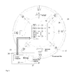
- An illustrative application of the invention is a phased array 19 applicator system, figure 5 , that can generate specific field conditions at certain locations in space or focus the RF energy into dielectric objects.
- the direct measurement of the currents or fields in metallic, slot or coil elements 26 allows direct quantification of the radiated or reactive fields generated by the electromagnetic field generating elements. More specifically, the invention provides the possibility to implicitly correct for the perturbations in the electromagnetic field generated due mutual coupling and mismatch in the applicator array 19 without explicitly measuring the coupling matrix and applying a correction to the excitations from the a radio frequency power source 18.
- the direct relationship between the current in a metallic element (or field in a slot based element) to the electrical output from the element sensors 4 to the radiated or reactive field can be determined by experimental or numerical means.
- the measurement devices 20 are put into calibration mode where the RF switch 13 in figure 4 is switched so that the calibration input phase reference signal from the bus 12 is measured by each measurement device to allow calibration of the phase of the device and also to remove the phase ambiguity of the ⁇ 2 quadrature phase splitter in the in-phase/quadrature demodulator 14.
Abstract
Description
- This invention relates to systems for creating specific electromagnetic field conditions within specific regions in space, or for focussing electromagnetic energy into dielectric objects with enhanced control.
- The ability to create specific electromagnetic field conditions is a core requirement in many medical applications from imaging to therapies. The present invention has applications in both these disciplines, as well as in phased array technology employed for communications and sensing applications.
- One application of this invention is the generation of specific field conditions at certain locations in the human body for the purpose of hyperthermia.
- The National Cancer Institute of the US National Institutes of Health defines Hyperthermia (also called thermal therapy or thermotherapy) as a type of cancer treatment in which body tissue is exposed to high temperatures (up to 45°C). Research has shown that high temperatures can damage and kill cancer cells, usually with minimal injury to normal tissues. By killing cancer cells and damaging proteins and structures within cells, hyperthermia may shrink tumors.
- This invention is concerned with local hyperthermia in which heat is applied to a small region, such as a tumor. It is possible to use various techniques to deliver energy to heat the tumor. In the context of this invention, either microwave or radio frequencies may be employed to apply the heat. Depending on the tumor location, there are several approaches to local hyperthermia. In the present case, an external approach is employed to treat tumors. The energy is applied by means of an applicator. The applicator is made up of a number of elements that are positioned around or near the appropriate region, and energy is focused on the tumor to raise its temperature using phased array techniques.
- Hyperthermia is often applied in combination with other therapies such as radiation therapy and/or chemotherapy. Hyperthermia has been performed as part of the treatment of many types of cancer, including sarcoma, melanoma, and cancers of the head and neck, brain, lung, esophagus, breast, bladder, rectum, liver, appendix, cervix, and peritoneal lining (mesothelioma).
- A phased array antenna is an antenna made up from a number of small(er) radiating elements, each with its own feed point. Phased array antennas are electrically steerable, which means the physical antenna can be stationary yet the antenna pattern can be manipulated by adjusting the amplitude weighting and phases of each element such that it is focused towards a particular region or such that it enables location of objects in space. Phased arrays can also be utilized to generate specific field conditions at certain locations in space or to focus radio frequency (RF) energy into dielectric objects in order to elevate the temperature of a target region inside the dielectric object or patient or induce fields and currents in a patient to excite atoms, nerves or other cellular mechanisms.
- A phased array can be used for hyperthermia by focusing RF energy into the patient such that the temperature is elevated. When a phased array is used for this purpose, it is termed an applicator as it applies energy to the patient. The phased array or applicator elements are fed by a multi-channel RF or microwave power source where the phase and amplitude signals are agile such that the RF or microwave energy can be focused in a target region or tumor. The number of array elements and placement of these elements with respect to the target region define the quality of the focus that can be achieved.
- The exemplar of RF hyperthermia will be used to illustrate the benefits of the invention. Although many systems have been proposed and used in the past for hyperthermia treatment of tumors, either alone or in conjunction with other therapies, the consistency and quality of the treatment has generally been lacking. Of utmost importance in local hyperthermia is the ability to apply or focus the energy from the applicator into the target region, tissue or tumor. To achieve satisfactory treatment outcomes, the whole target region should be heated sufficiently. To ensure this, a good electromagnetic applicator and patient specific models are most preferably used to plan and optimize the treatment. This step of accurately predicting the deposition of energy (and/or temperature rises) and optimizing such for best tumor treatment has been lacking in hyperthermia systems and has contributed to poor outcomes. During the treatment itself, in which RF or microwave power is applied to the hyperthermia array with the excitation amplitudes and phases as determined from the treatment plan, it is essential from a quality assurance point of view that the electromagnetic fields generated by each element is monitored to determine that the correct planned treatment is actually being applied.
- Common to all phased array antennas or hyperthermia applicators, is the requirement for a multi-channel source which can generate powerful signals with accurately controllable amplitude and phase with which to feed the individual electromagnetic field generating elements. It is not important for this invention which method is used to generate these signals.
- Multi-element or phased array applicators generally dispose the elements of the array around the patient with a water bolus filling the space between patient and array to provide surface cooling and lower reflections at the patient interface.
US patents 4672980 ,5251645 and5441532 all show typical phased array applicators. Each has the elements disposed in a circular array around the patient with the individual antenna elements (or pairs of elements inUS patent 4672980 ) excited by an RF power source with controlled amplitude and phase. None of these systems measure the actual applied signals or any power reflected which would reduce the effective radiated power. These factors therefore increase the uncertainty, InUS patents 5251645 and5441532 , field sensors are placed in and around the body of the patient to measure the overall applied field at those points and claims that using the values from these sensors the array excitation can be controlled such that the energy is focused into the target.US patent 4672980 uses a different approach where temperature measurement catheters are inserted into the patient and the system controlled to maximize the temperature increase in the target region. The draw-back of both approaches is that the human body is highly inhomogeneous and there is no intuitive relationship between applied excitations of the array and the energy deposition pattern. In essence these approaches assume that knowing the field or temperature at a few points is a substitute for knowing the radiation from each array element. - In the literature, Paulides et al 2007 describe a typical state of the art system, where the magnitude and phase of the applied signals to each applicator element is measured along with the reflected power, such that the control values can be adjusted such that the applied signals in light of reflections are as desired. When used with proper treatment planning this system has the potential to perform satisfactorily. However, the system relies on a computer simulation model fully defining the actual device and no means is available to fully account for changes in registration of the patient with respect to the applicator for the element impedance and mutual coupling element of the excitation.
- In the broader context of phased arrays for other applications,
US Patent 5867123 uses a technique of exciting single elements and observing the signals received by adjacent elements for built-in testing and failure analysis. Fulton and Chappell, 2009, review different calibration techniques for phased arrays and states arrays should be calibrated in an anechoic environment to determine the coupling matrix to enable compensation of the mutual coupling in the array. Additionally, it is noted that internal electronic hardware can be introduced for the monitoring of any changes from the initial calibrated coupling or transmit chain gains allowing correction to be applied. Lee et al, 1992/3, introduced a transmission (microstrip) line into the antenna panel to couple with each element so that transmit and receive functions of the electronics could be tested. The transmission line receives energy from all elements or injects energy into all elements of the array simultaneously. - Experience with radio frequency hyperthermia treatments and treatment planning and knowledge of the short-comings of systems of the nature discussed above, has led to important developments being made to the equipment and control systems. These developments greatly enhance certainty and consistency through assured field excitation. The present invention enhances consistency through assured field excitation from each antenna element of the array in the presence of mutual coupling, mismatch and reflections and hence uncertainty is reduced. Furthermore, the invention allows the coupling matrix to be determined more accurately than by the use of impedance or scattering matrix measurements, enabling a form of self-calibration which may be performed for each patient undergoing treatment. The key to achieving assured field excitation as determined by the treatment plan is the inclusion of sensors integrated into the antenna elements themselves which measure the phase and amplitude of current flowing in a metallic element or field in a slot-based element. These sensors, in the absence of mutual coupling or reflections, provide a measure proportional to the excitation. However, there is no requirement to consider mismatch or phase differences in connection leads, since it is the actual current (or field) in the antenna that is measured. With mutual coupling and reflections, the sensors measure the sum of all excitations, whatever their origin, and hence allows determination of the actual radiated field. Excitation of each element in turn and the measurement of the current (or field) in the excited antenna along with coupled excitation of all other antennas will allow the coupling matrix of the array to be directly determined.
-
US Patent 5867123 discussed above also excites each element in turn, but does not use this as a means to achieve self-calibration; even if it did, element mismatch would increase uncertainty. Lee et al, 1992/3 includes transmission lines introduced into the antenna panel, but lacks the ability to sense each antenna element individually, and does not disclose any motivation or ability to determine the antenna currents (or fields) due to either direct excitation or mutually coupled excitation. Hence, this system is used as a diagnostic tool rather than for control of field excitation. - The present invention comprises an array of electromagnetic field generating elements and integrates into each a sensor for measuring the phase and amplitude of the current flowing in a metallic element (antenna or coil) or field in a slot based element linked to a measurement device to enable measurement of both phase and amplitude of the electrical signals from each of the sensors, Furthermore, because signal picked up by each sensor is directly proportional to the phase and amplitude of the current or field in the associated electromagnetic field generating element where the current or field is the total current or field whose amplitude and phase is the sum of both the applied (from the radio frequency power source) and secondary excitations from mutual coupling and mismatch, hence the measured value represents the ideal excitation in the absence of mutual coupling and mismatch. This invention then uses embedded sensors in the antenna to add further functionality, for example, the direct excitation of each array element by a multichannel radio frequency or microwave power source, with individually controllable amplitude and phase, can be modified using a feedback controller such that the total excitation as measured by the embedded (current in a metallic or the field in a slot based antenna) sensor is the ideal array excitation without coupling or mismatch such that the superposition of the fields produced by each electromagnetic field generating element produces a specific electromagnetic field distribution in a defined volume or region. Implicitly correcting for the mutual coupling and mismatch without explicit knowledge of, and calculation based on, the mutual coupling and mismatch, termed the coupling matrix, such that changes in the coupling matrix due to presence of objects or changes thereof are inherently taken into account. Additionally, using sequential excitation of each element, the invention can directly determine the exact mutual coupling matrix of the array even in the presence of variations in source impedance and undefined cable lengths which can be useful in determining the initial excitation of the array of electromagnetic field generating elements such that feedback can more rapidly achieve the predefined ideal array excitation.
-
-
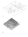
Fig. 1 : is illustrative of two adjacent array elements (cavity backed slots) one showing the incorporation of one possible implementation of the present invention -
Fig. 1a Two adjacent array elements (cavity backed slots), with the cavity screening of one element cut away -
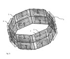
Fig. 2 : is illustrative of a whole RF hyperthermia applicator phased array, detail of small sensor elements not included -
Fig. 3 . Multi-channel radio frequency power source -
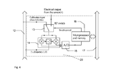
Fig. 4 . Measurement Device, single channel -
Fig. 5 : is illustrative of a whole system with phase and amplitude controlled multi-channel transmitter and phase/amplitude detectors connected by a measurement bus to the measurement and computer controllers. -
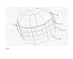
Fig. 6 . is illustrative of an array for radio frequency hyperthermia in which a water bolus is shown for placement between the array elements and the patient to reduce reflection and facilitate surface cooling. - The invention relates to a system made up of five integral parts, it is the novel features of some of these parts and the integration and use of them as a whole that provides the innovation. The first integral part are the electromagnetic field generating elements,
figure 1 , which are arranged into an array of arbitrary geometry,figure 2 . The array of elements is connected to a radio frequency power source,figure 3 , which has a number of independently phase and amplitude computer controllable channels. Integrated into each electromagnetic field generating element is a current (or field) sensing element which produces an electrical output proportional to the electromagnetic field generated, each electrical signal is measured by a measurement device that measures both amplitude and phase,figure 4 . The measurement data is communicated via a measurement bus to a measurement controller. A control computer utilizes the measurement data to control the radio frequency power source in such a way that the electromagnetic fields generated are the required fields, the whole system and the interconnections are shown infigure 5 . - An illustrative application of the invention is a phased
array 19 applicator system,figure 5 , that can generate specific field conditions at certain locations in space or focus the RF energy into dielectric objects. The direct measurement of the currents or fields in metallic, slot orcoil elements 26 allows direct quantification of the radiated or reactive fields generated by the electromagnetic field generating elements. More specifically, the invention provides the possibility to implicitly correct for the perturbations in the electromagnetic field generated due mutual coupling and mismatch in theapplicator array 19 without explicitly measuring the coupling matrix and applying a correction to the excitations from the a radiofrequency power source 18. The direct relationship between the current in a metallic element (or field in a slot based element) to the electrical output from the element sensors 4 to the radiated or reactive field can be determined by experimental or numerical means. - An objective of the invention is to provide an improved means of determining the actual radiated or reactive near field of each
element 26,figure 1 , in an array of electromagneticfield generating elements 19 for radio frequency hyperthermia applications,figures 2 and6 , where the immediate load due to patient, dielectric objects and other system components changes the coupling between and matching seen at theinput ports 3 of theelements 26 or where the source impedance of the radio frequencypower source channels 11 are not well characterized. - A further objective of the invention is to provide higher levels of confidence that the real array excitation from the multichannel radio
frequency power source 18 is the planned excitation ensuring higher quality control of the field distribution generated by thearray 19 of electromagnetic field generating elements. To enable this, the electromagnetic field generated is measured,figure 4 , using a measurement device such as a vector volt meter or in-phase/quadrature demodulator of sufficient sensitivity. Additional circuitry may be added, as shown infigure 4 , to allow self calibration of the amplitude and phase detectors facilitated by not only distributing the local oscillator via a bus but also a phase reference which can be switched to the input to allow calibration and / or phase ambiguity removal further reducing the uncertainty. - Additionally, the invention provides a new paradigm for the correction of array mutual coupling by implicitly measuring the generated electromagnetic field with the mutual coupling and mismatch accounted for. Hence the actual and planned excitations have a low deviation in particular in the presence of variations that could not be modeled during treatment planning.
- Furthermore, the invention does not limit the geometry or placement of the
applicator array elements 26,figure 2 , around or close to the target area and can be applied to any generic array of electromagneticfield generating elements 19. In particular there are no limits on the proximity of dielectric objects such as patients or other mutual coupling or element matching modifying attributes. - Though the integrated current or field sensors 4,
figure 1 , implicitly take into account mismatch and mutual coupling, the invention allows the coupling matrix (that describes the mismatch and mutual coupling) of the applicator array of electromagnetic field generating elements to be directly determined with greater accuracy than the standard technique of calculating the coupling matrix from the S-parameters and with the convenience of not having to disconnect theapplicator array 19 from the radiofrequency power source 18,figure 5 , and connect it to a network analyzer. By excitation of eachelement 2 in turn using the radio frequency power source and measurement of the requisite currents (or fields) 5 in all theelements 2 using themeasurement device 18 the coupling matrix can be determined more accurately as the non-ideal output impedances of eachamplifier 10 and connecting cable lengths between radio frequencypower source output 11 and electromagneticfield generating element 3 are inherently accounted for. - The invention whilst providing this very important information on the radiated or reactive field from each
element 26 also gives the ability to detect whichoutput channel 11 from the multi channel radiofrequency power source 18 has been connected to which electromagneticfield generating element 26 in thearray 19 and hence remove the possibility of incorrect connection and the chance of a treatment that is completely in error. - With a
measurement device 20 integrated with eachelement 26 it becomes possible to have an individual identity for each electromagnetic field generating element allowing individual calibrations for the element- measuring device combination to be assigned. Therefore, calibration data can be assigned to the correct element for means of quality control, ease of use and security. A calibration facility can therefore provide an accredited calibration that can be attributed to a given element. Enabling thewhole array 19 to be modular withreplaceable elements 26 and provide 'plug and play' capabilities. - The preferred embodiment can be described in the context of an RF hyperthermia applicator system,
figures 5 . This hyperthermia applicator system consists of both hardware and a computer control systems and these systems allow enhanced use paradigms that illustrate the utility of the invention. - The Hyperthermia applicator system illustrated in
figure 5 takes the form of a ring array applicator made up of electromagnetic field generating elements,figure 2 , where the electromagnetic field generating elements,figure 1 , are placed around the body in the vicinity of the region to be heated. It is not always the case that elements need to form an entire ring, but might be placed predominantly on one side of the patient. In this specific array however the E-field vector of all elements should be predominantly aligned in the same direction within the target region, but this is not a requirement in all applications of the system. The region between the applicator and the patient is filled by a water bolus,figure 6 , of a defined shape which affords three things: - 1. Miniaturization of the antenna elements due to the high dielectric constant.
- 2. Minimization of the discontinuity between antenna and patient as the dielectric properties of water and tissue are much more similar than air and tissue.
- 3. To provide cooling of the patient skin as high levels of specific energy absorption can occur on the body surface.
- Cavity backed slot antennas,
figure 1 , are chosen as the electromagnetic field generating elements in our preferred embodiment as they provide: Low profile, good polarization purity, accurate dimensions through photolithographic printed circuit processing techniques, ease of manufacture, robust structure, relatively broadband response and hence tolerance to environment changes. With aslot antenna 2 embodiment then an appropriate method of sensing is through sensing of the field in the slot by means of small coupling loops 4. The loops 4 are sufficiently small such that the amount of coupled power is small compared to the total, which could be 100s of Watts, which is applied to theantenna port 3 and so that the field in theslot 2 remains unperturbed by the measurement. - Each slot element in the applicator is fed from a phase and amplitude controllable radio frequency power source,
figure 3 . The fields in each applicator element slot due to its own excitation and fields coupled from other elements are sensed 4 and measured usingmeasurement device 20 consisting of a phase / amplitude detectors,figure 4 , and the values communicated to acontrol system 21. In this case an in-phase/quadrature demodulator 14 in conjunction with a pair of analog todigital converters 15 is used to measure the in-phase and quadrature voltage levels. The digital signal is then converted into a magnitude and phase using themicroprocessor 16 and communicated to themeasurement controller 21 via ameasurement bus 17. - The
control system 22 sets the amplitudes and phases 8 of the multi channel radiofrequency power source 18 andmeasures 20 the resultant fields 4 applied from eachelement 26 and affords feedback control to ensure the applied fields are the required fields. - A typical usage paradigm is that a validated numerical electromagnetic model of the
applicator array 19 is used with a patient specific EM model derived from CT, MRI or other image data within a treatment planning software. In the treatment planning software the target region or regions for treatment is defined and the optimum ideal excitation values (or non-ideal taking into account mutual coupling and mismatch based on the mutual coupling matrix for the model which may or may not closely correspond to the real coupling matrix due to the possible errors previously mentioned from which the ideal excitation can be calculated) are derived and the corresponding EM-field, SAR or temperature rise values across the whole of the target region or regions generated. - The target excitations are then transferred to the treatment control software and the patient placed in the
applicator 19 at the position modeled in the treatment planning. Thewater bolus 25 is filled with demonized water. - The
measurement devices 20 are put into calibration mode where theRF switch 13 infigure 4 is switched so that the calibration input phase reference signal from thebus 12 is measured by each measurement device to allow calibration of the phase of the device and also to remove the phase ambiguity of the ÷2 quadrature phase splitter in the in-phase/quadrature demodulator 14. - Each radio frequency
power source output 11 channel of the multi channel radiofrequency power source 18 is excited in turn to determine whichapplicator element 26 is connected to each output channel and to measure the fields/currents 4 induced in all the elements to generate the actual mutual coupling matrix for thearray 19 at the time of treatment. In addition the phase and amplitude offset due to the connecting cables or transmit channel differences can be eliminated or calibrated out. Phase shifts due to variation in applicator element impedance from the ideal, for example due to patient proximity and hence change in the dielectric constant immediate environment, are also eliminated. - Treatment is commenced with
radio frequency power 18 being applied to eachelement 26 based on the treatment planning, either based on ideal or corrected (using the coupling matrix) excitations, the actual excitation levels are determined using the field monitoring 4 andmeasurement 20 and controlled by thefeedback controller 27 to correct for any deviation from the desired excitation levels. Throughout the treatment the total output power from eachchannel 11 can be controlled 8 and the correct relationship between amplitudes and phase monitored 20 and controlled to the correct value. While the invention herein disclosed has been described by means of specific embodiments and applications thereof, numerous modifications and variations could be made thereto by those skilled in the art without departing from the scope of the invention set forth in the claims. -
- United States Patent
5251645 "Adaptive nulling hyperthermia array " Inventors: Fenn, Alan J. (Wayland, MA) Assignee: Massachusetts Institute of Technology (Cambridge, MA). - United States Patent
4672980 "System and method for creating hyperthermia in tissue " Inventors: Turner, Paul F. Assignee: BSD Medical Corporation (Salt Lake City, UT) - United States Patent
US5441532 and WIPO Patent ApplicationWO/1993/000132 "ADAPTIVE FOCUSING AND NULLING HYPERTHERMIA ANNULAR AND MONOPOLE PHASED ARRAY APPLICATORS", Inventors: Fenn, Alan J. (Wayland, MA) Assignee: Massachusetts Institute of Technology (Cambridge, MA). -
- Calibration techniques for digital phased arrays, Fulton, C.; Chappell, W.; Microwaves, Communications, Antennas and Electronics Systems, 2009. COMCAS 2009. IEEE International Conference on Communications, Antennas and Electronic Systems. Publication Year: 2009 , Page(s): 1 -10
- A Built-In Performance-Monitoring/Fault Isolation and Correction (PM/FIC) System for Active Phased-Array Antennas, Kuan-Min Lee, Ruey-Shi Chu, and Sien-Chang Liu, IEEE TRANSACTIONS ON ANTENNAS AND PROPAGATION, VOL. 41, NO. 11, NOVEMBER 1993
- K. M. Lee, R. S. Chu, and S. C. Liu, "A performance monitoring/fault isolation and correction system of a phased array antenna using transmission-line signal injection with phase toggling method," IEEE AP-S 1992 Symposium Digest (Chicago, IL), July 18-25, 1992, vol. 1, pp. 429-432.
Claims (18)
- A system for producing a predetermined electromagnetic field distribution in a defined volume or region, comprising a multi-channel radio frequency or microwave power source (18) connected to an array (19) of electromagnetic field generating elements (26), and a feedback controller (27) for controlling the radio frequency or microwave power source (18) to achieve the desired electromagnetic field produced by each element (26) such that the superposition of the fields produced by each electromagnetic field generating element produces said predetermined electromagnetic field distribution in said defined volume, the feedback to the controller (27) being the amplitude and phase of the electromagnetic field generated by each of the generating elements, characterised in that current or field (electric, magnetic or electromagnetic) sensors (4) are integrated into each electromagnetic field generating element (26) for sensing directly the element excitation and hence indirectly the amplitude and phase of the electromagnetic field generated by each of the generating elements (26), said sensors (4) being interconnected with a measurement device (20) for determining the amplitude and phase of the signals from each sensor (4) and hence the electromagnetic field produced by each element (26).
- A system according to claim 1 in which the electromagnetic field generating elements (26) are antennas (based on conductor or slot(2) elements) or coils.
- A system according to claim 1 or claim 2, in which the multi-channel radio frequency power source (18) is provided with control means for individually controlling amplitudes and phases (8) to produce individually controlled radio frequency outputs (11).
- A system according to any one of claims 1 to 3, in which the electromagnetic field generating elements (26) are provided with a feed port (3) to which radio frequency power from outputs (11) is applied, and one or more integrated sensors (4) for measuring the phase and amplitude of current flowing in a metallic element or field in a slot-based element (2) (which is the analogue of the current in a metal element), the output of the sensors being an electrical signal which is a measure of said current or field.
- A system according to any one of claims 1 to 4, in which the electromagnetic field generating elements (26) are situated into an array (19) of arbitrary configuration such that each element(26) may be excited by the radio frequency power output (11) of one channel of the radio frequency power source (18) and such that the electrical signal from the integrated sensors (4) of the field generating elements (26) is proportional to the radio frequency current (or field in the case of slot) in each element (2).
- A system according to any one of claims 1 to 5, in which the electromagnetic field generating elements (26) having integrated current (or field in the case of slot based elements) sensors (4) provide a direct indication of the relative amplitude and phase of the electromagnetic field produced by each electromagnetic field generating element in the presence of mutual coupling between elements and hence afford control of the applied fields in the presence of mutual coupling.
- A system according to any one of claims 1 to 6, in which the measurement device (20) is of sufficient dynamic range to enable measurement of both phase and amplitude of the electrical signals from the sensors (4).
- A system according to any one of the preceding claims in which the measurement device (20) is an In-phase/Quadrature (IQ) demodulator (14) or vector voltmeter, whereby multiplication of the measured electrical signals by a calibration factor can enable the electromagnetic field produced by each individual electromagnetic field generating element (26) to be quantified.
- A system according to any one of claims 1 to 8, in which each electromagnetic field generating element (26) is integrated with a channel of the measurement device (20) to form a module such that each module may be provided with an individual identity or serial number such that calibration data can be seamlessly assigned to each electromagnetic field generating element, modules may be exchanged to enable rapid repair and / or servicing, and whereby the individual identity provides 'plug and play' capability with automatic detection of different hardware and assignment of calibration data.
- A system according to any one of claims 1 to 9, in which the feedback controller (27) enables adjustment of the amplitude and phase (8) of each individual channel of the multi channel radio frequency power source (18) such that the electromagnetic field radiating element (26) currents (or fields in the case of slot based elements) sensed by the sensors (4) and measured by the measurement device (20) are the desired currents or fields.
- A system according to any one of claims 1 to 10, adapted to focus radio frequency energy into one or more dielectric objects or one or multiple regions of said one or more dielectric objects, in order to excite atoms, molecules or cellular structures or to elevate the temperature within said one or more objects or one or multiple regions within the dielectric object or objects.
- A system according to any one of claims 1 to 11, adapted to induce fields and currents into a human patient or specific regions within the patient to excite atoms, molecules, nerves or other chemical or cellular mechanisms.
- A system according to any one of claims 1 to 10, adapted to locate objects in space.
- A system according to any one of claims 1 to 13, in which control of the multi-channel radio frequency power source (18) connected to the array of electromagnetic field generating elements (19) in which the sensed currents (or fields in the case of slot based elements) are the desired current or field levels of the ideal array(19) without coupling or mismatch, implicitly correcting for the mutual coupling between and mismatch of the electromagnetic field generating elements without explicit knowledge of, and calculation based on, the mutual coupling and mismatch.
- A system according to any one of claims 1 to 14, in which changes in the mutual coupling and mismatch due to presence of dielectric or metallic objects (e.g., patient, water bolus (25), support structures) or changes in the position of these objects are inherently taken into account.
- A system according to any one of claims 1 to 15, in which the mutual coupling and mismatch, described in terms of a coupling matrix, of an arbitrary array (19) of electromagnetic field generating elements (26) can be determined directly by excitation (11) of each electromagnetic field generating element (26) in turn by a single channel of the multi channel radio frequency power source (18) and using the currents or fields measured by all the channels the measurement system(20) from all the integrated sensors(4) the coupling matrix for the array can be determined more accurately than by the use of standard network analysis methods as the non-ideal output impedances of each amplifier and connecting cable lengths are inherently accounted for.
- A system according to any one of claims 1 to 16 in which the coupling matrix is used to calculate the initial amplitudes and phases of the radio frequency outputs (11) of the multi channel radio frequency power source (18) and the currents or fields measured by the measurement system (20) from the current or field sensors (4) integral to the electromagnetic field generating elements (26) and the feedback controller (27) used to fine tune the system to provide the desired currents or fields in the electromagnetic field generating elements.
- A system according to any one of claims 1 to 17 in which each radio frequency output(11) from the multi channel radio frequency power source (18) that connects to individual electromagnetic field generating elements (26) can be connected in any order to the array (19) of electromagnetic field generating elements and the integrated current or field sensor (4) used to determine which radio frequency output is connected to which electromagnetic field generating element and define the correct mapping between output and element eliminating incorrect electromagnetic field generation due to incorrect interconnection.
Priority Applications (1)
| Application Number | Priority Date | Filing Date | Title |
|---|---|---|---|
| PL11180243T PL2425794T3 (en) | 2010-09-06 | 2011-09-06 | Electromagnetic field applicator array with integral field sensors for implicit correction of mutual coupling and mismatch |
Applications Claiming Priority (1)
| Application Number | Priority Date | Filing Date | Title |
|---|---|---|---|
| CH01439/10A CH704177A2 (en) | 2010-09-06 | 2010-09-06 | Array antenna structure for generating specific electromagnetic field distributions with integrated probes for implicit correction of mutual coupling and mismatch. |
Publications (2)
| Publication Number | Publication Date |
|---|---|
| EP2425794A1 true EP2425794A1 (en) | 2012-03-07 |
| EP2425794B1 EP2425794B1 (en) | 2015-09-02 |
Family
ID=44645100
Family Applications (1)
| Application Number | Title | Priority Date | Filing Date |
|---|---|---|---|
| EP11180243.5A Active EP2425794B1 (en) | 2010-09-06 | 2011-09-06 | Electromagnetic field applicator array with integral field sensors for implicit correction of mutual coupling and mismatch |
Country Status (11)
| Country | Link |
|---|---|
| US (1) | US9763734B2 (en) |
| EP (1) | EP2425794B1 (en) |
| JP (1) | JP5925780B2 (en) |
| CN (1) | CN103200894B (en) |
| CA (1) | CA2808670A1 (en) |
| CH (1) | CH704177A2 (en) |
| DK (1) | DK2425794T3 (en) |
| ES (1) | ES2552159T3 (en) |
| PL (1) | PL2425794T3 (en) |
| PT (1) | PT2425794E (en) |
| WO (1) | WO2012032053A1 (en) |
Cited By (1)
| Publication number | Priority date | Publication date | Assignee | Title |
|---|---|---|---|---|
| EP3131327A4 (en) * | 2014-05-05 | 2017-05-17 | Huawei Technologies Co. Ltd. | Rcu and rf port matching electric tilt antenna, base station and method |
Families Citing this family (13)
| Publication number | Priority date | Publication date | Assignee | Title |
|---|---|---|---|---|
| US9669231B1 (en) * | 2011-11-04 | 2017-06-06 | Parmenides, Inc. | Apparatus and method for hyperthermic treatments |
| US10232188B2 (en) | 2011-11-04 | 2019-03-19 | Thermofield Inc. | Single cable apparatus and method for hyperthermic treatments |
| US11911629B2 (en) | 2013-03-11 | 2024-02-27 | NeurEM Therapeutics, Inc. | Treatment of primary and metastatic brain cancers by transcranial electromagnetic treatment |
| US11752356B2 (en) * | 2013-03-11 | 2023-09-12 | NeuroEM Therapeutics, Inc. | Systems for controlling power to differently loaded antenna arrays |
| US11759650B2 (en) | 2013-03-11 | 2023-09-19 | NeuroEM Therapeutics, Inc. | Immunoregulation, brain detoxification, and cognitive protection by electromagnetic treatment |
| US11813472B2 (en) | 2013-03-11 | 2023-11-14 | NeuroEM Therapeutics, Inc. | Systems for sensing proper emitter array placement |
| CN103646126A (en) * | 2013-11-01 | 2014-03-19 | 南京信息工程大学 | Design method of micro-strip array focusing antenna and micro-strip array focusing antenna |
| US11794028B2 (en) | 2014-03-11 | 2023-10-24 | NeuroEM Therapeutics, Inc. | Transcranial electromagnetic treatment |
| CN103990228B (en) * | 2014-05-15 | 2016-02-17 | 哈尔滨易奥秘科技发展有限公司 | A kind of can the multi-electrode bispectrum radio frequency tumour thermal therapeutic apparatus of focused electromagnetic |
| KR101676192B1 (en) * | 2015-10-02 | 2016-11-15 | (의료)길의료재단 | Multi-channel RF coil array for MRI |
| WO2017184582A1 (en) * | 2016-04-18 | 2017-10-26 | Alps South Europe, S.R.O. | Induction heater and dispenser |
| CN111939479A (en) * | 2020-08-20 | 2020-11-17 | 哈尔滨乔然科技有限公司 | Phased array thermotherapy machine and control method thereof |
| CN113456213B (en) * | 2021-08-13 | 2022-08-02 | 卡本(深圳)医疗器械有限公司 | Artificial intelligence-based radio frequency ablation parameter optimization and information synthesis method and system |
Citations (6)
| Publication number | Priority date | Publication date | Assignee | Title |
|---|---|---|---|---|
| US4672980A (en) | 1980-04-02 | 1987-06-16 | Bsd Medical Corporation | System and method for creating hyperthermia in tissue |
| WO1993000132A1 (en) | 1991-06-26 | 1993-01-07 | Massachusetts Institute Of Technology | Adaptive focusing and nulling hyperthermia annular and monopole phased array applicators |
| US5441532A (en) | 1991-06-26 | 1995-08-15 | Massachusetts Institute Of Technology | Adaptive focusing and nulling hyperthermia annular and monopole phased array applicators |
| US5867123A (en) | 1997-06-19 | 1999-02-02 | Motorola, Inc. | Phased array radio frequency (RF) built-in-test equipment (BITE) apparatus and method of operation therefor |
| US6208903B1 (en) * | 1995-06-07 | 2001-03-27 | Medical Contouring Corporation | Microwave applicator |
| WO2008068485A2 (en) * | 2006-12-08 | 2008-06-12 | Medical Device Innovations Limited | Microwave array applicator for hyperthermia |
Family Cites Families (12)
| Publication number | Priority date | Publication date | Assignee | Title |
|---|---|---|---|---|
| US4798215A (en) * | 1984-03-15 | 1989-01-17 | Bsd Medical Corporation | Hyperthermia apparatus |
| US4885589A (en) * | 1988-09-14 | 1989-12-05 | General Electric Company | Optical distribution of transmitter signals and antenna returns in a phased array radar system |
| WO2004025321A1 (en) | 2002-09-11 | 2004-03-25 | Lockheed Martin Corporation | Cce calibration with an array of calibration probes interleaved with the array antenna |
| US6904323B2 (en) | 2003-05-14 | 2005-06-07 | Duke University | Non-invasive apparatus and method for providing RF energy-induced localized hyperthermia |
| US20060265034A1 (en) * | 2005-04-05 | 2006-11-23 | Ams Medical Sa | Microwave devices for treating biological samples and tissue and methods for using same |
| US7471237B2 (en) | 2006-03-22 | 2008-12-30 | The Boeing Company | Built-in missile RADAR calibration verification |
| US20080007453A1 (en) | 2006-06-12 | 2008-01-10 | Bill Vassilakis | Smart antenna array over fiber |
| US8700176B2 (en) * | 2006-07-27 | 2014-04-15 | Pollogen Ltd. | Apparatus and method for non-invasive treatment of skin tissue |
| EP1911410A1 (en) * | 2006-10-10 | 2008-04-16 | Wavelight Aesthetic GmbH | Device for dermatolgic treatments |
| CN101711134B (en) * | 2007-04-19 | 2016-08-17 | 米勒玛尔实验室公司 | Tissue is applied the system of microwave energy and in organized layer, produces the system of tissue effect |
| US20080281386A1 (en) * | 2007-05-09 | 2008-11-13 | Tessaron Medical, Inc. | Systems and methods for treating body tissue |
| US9415234B2 (en) * | 2012-07-06 | 2016-08-16 | Pyrexar Medical Inc. | Tissue heating prediction using feedpoint EM field determination |
-
2010
- 2010-09-06 CH CH01439/10A patent/CH704177A2/en not_active Application Discontinuation
-
2011
- 2011-09-06 JP JP2013526511A patent/JP5925780B2/en active Active
- 2011-09-06 PL PL11180243T patent/PL2425794T3/en unknown
- 2011-09-06 ES ES11180243.5T patent/ES2552159T3/en active Active
- 2011-09-06 US US13/261,600 patent/US9763734B2/en active Active
- 2011-09-06 CN CN201180053379.7A patent/CN103200894B/en active Active
- 2011-09-06 CA CA2808670A patent/CA2808670A1/en not_active Abandoned
- 2011-09-06 PT PT111802435T patent/PT2425794E/en unknown
- 2011-09-06 EP EP11180243.5A patent/EP2425794B1/en active Active
- 2011-09-06 WO PCT/EP2011/065402 patent/WO2012032053A1/en active Application Filing
- 2011-09-06 DK DK11180243.5T patent/DK2425794T3/en active
Patent Citations (7)
| Publication number | Priority date | Publication date | Assignee | Title |
|---|---|---|---|---|
| US4672980A (en) | 1980-04-02 | 1987-06-16 | Bsd Medical Corporation | System and method for creating hyperthermia in tissue |
| WO1993000132A1 (en) | 1991-06-26 | 1993-01-07 | Massachusetts Institute Of Technology | Adaptive focusing and nulling hyperthermia annular and monopole phased array applicators |
| US5251645A (en) | 1991-06-26 | 1993-10-12 | Massachusetts Institute Of Technology | Adaptive nulling hyperthermia array |
| US5441532A (en) | 1991-06-26 | 1995-08-15 | Massachusetts Institute Of Technology | Adaptive focusing and nulling hyperthermia annular and monopole phased array applicators |
| US6208903B1 (en) * | 1995-06-07 | 2001-03-27 | Medical Contouring Corporation | Microwave applicator |
| US5867123A (en) | 1997-06-19 | 1999-02-02 | Motorola, Inc. | Phased array radio frequency (RF) built-in-test equipment (BITE) apparatus and method of operation therefor |
| WO2008068485A2 (en) * | 2006-12-08 | 2008-06-12 | Medical Device Innovations Limited | Microwave array applicator for hyperthermia |
Non-Patent Citations (6)
| Title |
|---|
| FENN, ALAN J., ADAPTIVE NULLING HYPERTHERMIA ARRAY |
| FENN, ALAN J.: "ADAPTIVE FOCUSING AND NULLING HYPERTHERMIA ANNULAR AND MONOPOLE PHASED ARRAYAPPLICATORS", MASSACHUSETTS INSTITUTE OF TECHNOLOGY |
| FULTON, C., CHAPPELL, W.: "Calibration techniques for digital phased arrays", MICROWAVES, COMMUNICATIONS, ANTENNAS AND ELECTRONICS SYSTEMS, 2009 |
| IEEE INTERNATIONAL CONFERENCE ON COMMUNICATIONS, ANTENNAS AND ELECTRONIC SYSTEMS, 2009, pages 1 - 10 |
| K. M. LEE, R. S. CHU, S. C. LIU: "A performance monitoring/fault isolation and correction system of a phased array antenna using transmission-line signal injection with phase toggling method", IEEE AP-S 1992 SYMPOSIUM DIGEST (CHICAGO, IL, no. 1, 18 July 1992 (1992-07-18), pages 429 - 432, XP000342359, DOI: doi:10.1109/APS.1992.221915 |
| KUAN-MIN LEE, RUEY-SHI CHU, SIEN-CHANG LIU: "A Built-In Performance-Monitoring/Fault Isolation and Correction (PM/FIC) System for Active Phased-Array Antennas", IEEE TRANSACTIONS ON ANTENNAS AND PROPAGATION, vol. 41, no. 11, November 1993 (1993-11-01) |
Cited By (2)
| Publication number | Priority date | Publication date | Assignee | Title |
|---|---|---|---|---|
| EP3131327A4 (en) * | 2014-05-05 | 2017-05-17 | Huawei Technologies Co. Ltd. | Rcu and rf port matching electric tilt antenna, base station and method |
| US9763108B2 (en) | 2014-05-05 | 2017-09-12 | Huawei Technologies Co., Ltd. | Remote electrical tilt antenna, base station, and method for matching RCU with RF port |
Also Published As
| Publication number | Publication date |
|---|---|
| PL2425794T3 (en) | 2016-07-29 |
| ES2552159T3 (en) | 2015-11-26 |
| US9763734B2 (en) | 2017-09-19 |
| US20130237742A1 (en) | 2013-09-12 |
| DK2425794T3 (en) | 2015-11-09 |
| WO2012032053A1 (en) | 2012-03-15 |
| JP2013538612A (en) | 2013-10-17 |
| CN103200894B (en) | 2017-06-13 |
| EP2425794B1 (en) | 2015-09-02 |
| PT2425794E (en) | 2015-12-24 |
| CA2808670A1 (en) | 2012-03-15 |
| CN103200894A (en) | 2013-07-10 |
| CH704177A2 (en) | 2012-05-31 |
| JP5925780B2 (en) | 2016-05-25 |
Similar Documents
| Publication | Publication Date | Title |
|---|---|---|
| EP2425794B1 (en) | Electromagnetic field applicator array with integral field sensors for implicit correction of mutual coupling and mismatch | |
| US9415234B2 (en) | Tissue heating prediction using feedpoint EM field determination | |
| US20100253338A1 (en) | Magnetic resonance method and apparatus for reducing rf heating in the patient | |
| US20110193566A1 (en) | Multichannel absorberless near field measurement system | |
| WO2009046516A1 (en) | Multichannel absorberless near field measurement system | |
| EP2126600B1 (en) | A model based positioning system | |
| Steensma et al. | Introduction of the snake antenna array: geometry optimization of a sinusoidal dipole antenna for 10.5 T body imaging with lower peak SAR | |
| Stakhursky et al. | Real-time MRI-guided hyperthermia treatment using a fast adaptive algorithm | |
| Eigentler et al. | Wideband self‐grounded bow‐tie antenna for thermal mr | |
| Bakker et al. | Design and test of a 434 MHz multi-channel amplifier system for targeted hyperthermia applicators | |
| Restivo et al. | Improving peak local SAR prediction in parallel transmit using in situ S‐matrix measurements | |
| US11426080B2 (en) | Real-time imaging system for monitoring and control of thermal therapy treatments | |
| Williams et al. | Ultra-high field MRI: parallel-transmit arrays and RF pulse design | |
| van Leeuwen et al. | The coax dipole: a fully flexible coaxial cable dipole antenna with flattened current distribution for body imaging at 7 Tesla | |
| WO2007112546A1 (en) | Multichannel absorberless near field measurement system | |
| Hornsleth et al. | Quality assurance for radiofrequency regional hyperthermia | |
| US20220187391A1 (en) | Multi-frequency high electric field systems for magnetic resonance imaging safety testing of medical devices | |
| US20220088394A1 (en) | Method and system for validating safety of a medical device when exposed to magnetic resonance imaging fields | |
| CN102551716B (en) | Magnetic resonance system and magnetic resonance method | |
| Sumser et al. | Dual-function MR-guided hyperthermia: An innovative integrated approach and experimental demonstration of proof of principle | |
| Sun et al. | A retrofit to enable dynamic steering for transmit arrays without multiple amplifiers | |
| Raskmark et al. | Multi-applicator hyperthermia system description using scattering parameters | |
| Wust et al. | Scanning E-field sensor device for online measurements in annular phased-array systems | |
| Capstick et al. | Novel applicator for local RF hyperthermia treatment using improved excitation control | |
| Qiu et al. | Simultaneous radiofrequency (RF) heating and magnetic resonance (MR) thermal mapping using an intravascular MR imaging/RF heating system |
Legal Events
| Date | Code | Title | Description |
|---|---|---|---|
| AK | Designated contracting states |
Kind code of ref document: A1 Designated state(s): AL AT BE BG CH CY CZ DE DK EE ES FI FR GB GR HR HU IE IS IT LI LT LU LV MC MK MT NL NO PL PT RO RS SE SI SK SM TR |
|
| AX | Request for extension of the european patent |
Extension state: BA ME |
|
| PUAI | Public reference made under article 153(3) epc to a published international application that has entered the european phase |
Free format text: ORIGINAL CODE: 0009012 |
|
| 17P | Request for examination filed |
Effective date: 20120822 |
|
| 17Q | First examination report despatched |
Effective date: 20130626 |
|
| GRAP | Despatch of communication of intention to grant a patent |
Free format text: ORIGINAL CODE: EPIDOSNIGR1 |
|
| INTG | Intention to grant announced |
Effective date: 20150317 |
|
| GRAS | Grant fee paid |
Free format text: ORIGINAL CODE: EPIDOSNIGR3 |
|
| GRAA | (expected) grant |
Free format text: ORIGINAL CODE: 0009210 |
|
| AK | Designated contracting states |
Kind code of ref document: B1 Designated state(s): AL AT BE BG CH CY CZ DE DK EE ES FI FR GB GR HR HU IE IS IT LI LT LU LV MC MK MT NL NO PL PT RO RS SE SI SK SM TR |
|
| REG | Reference to a national code |
Ref country code: GB Ref legal event code: FG4D |
|
| REG | Reference to a national code |
Ref country code: AT Ref legal event code: REF Ref document number: 746041 Country of ref document: AT Kind code of ref document: T Effective date: 20150915 Ref country code: CH Ref legal event code: EP |
|
| REG | Reference to a national code |
Ref country code: IE Ref legal event code: FG4D |
|
| REG | Reference to a national code |
Ref country code: DE Ref legal event code: R096 Ref document number: 602011019324 Country of ref document: DE |
|
| REG | Reference to a national code |
Ref country code: FR Ref legal event code: PLFP Year of fee payment: 5 |
|
| REG | Reference to a national code |
Ref country code: DK Ref legal event code: T3 Effective date: 20151103 |
|
| REG | Reference to a national code |
Ref country code: ES Ref legal event code: FG2A Ref document number: 2552159 Country of ref document: ES Kind code of ref document: T3 Effective date: 20151126 |
|
| REG | Reference to a national code |
Ref country code: SE Ref legal event code: TRGR |
|
| REG | Reference to a national code |
Ref country code: PT Ref legal event code: SC4A Free format text: AVAILABILITY OF NATIONAL TRANSLATION Effective date: 20151130 |
|
| REG | Reference to a national code |
Ref country code: CH Ref legal event code: PK Free format text: BERICHTIGUNG INHABER Ref country code: CH Ref legal event code: NV Representative=s name: SCHMAUDER AND PARTNER AG PATENT- UND MARKENANW, CH |
|
| PG25 | Lapsed in a contracting state [announced via postgrant information from national office to epo] |
Ref country code: LV Free format text: LAPSE BECAUSE OF FAILURE TO SUBMIT A TRANSLATION OF THE DESCRIPTION OR TO PAY THE FEE WITHIN THE PRESCRIBED TIME-LIMIT Effective date: 20150902 Ref country code: GR Free format text: LAPSE BECAUSE OF FAILURE TO SUBMIT A TRANSLATION OF THE DESCRIPTION OR TO PAY THE FEE WITHIN THE PRESCRIBED TIME-LIMIT Effective date: 20151203 Ref country code: LT Free format text: LAPSE BECAUSE OF FAILURE TO SUBMIT A TRANSLATION OF THE DESCRIPTION OR TO PAY THE FEE WITHIN THE PRESCRIBED TIME-LIMIT Effective date: 20150902 |
|
| REG | Reference to a national code |
Ref country code: NL Ref legal event code: FP |
|
| REG | Reference to a national code |
Ref country code: LT Ref legal event code: MG4D |
|
| PG25 | Lapsed in a contracting state [announced via postgrant information from national office to epo] |
Ref country code: RS Free format text: LAPSE BECAUSE OF FAILURE TO SUBMIT A TRANSLATION OF THE DESCRIPTION OR TO PAY THE FEE WITHIN THE PRESCRIBED TIME-LIMIT Effective date: 20150902 |
|
| PG25 | Lapsed in a contracting state [announced via postgrant information from national office to epo] |
Ref country code: IS Free format text: LAPSE BECAUSE OF FAILURE TO SUBMIT A TRANSLATION OF THE DESCRIPTION OR TO PAY THE FEE WITHIN THE PRESCRIBED TIME-LIMIT Effective date: 20160102 Ref country code: CZ Free format text: LAPSE BECAUSE OF FAILURE TO SUBMIT A TRANSLATION OF THE DESCRIPTION OR TO PAY THE FEE WITHIN THE PRESCRIBED TIME-LIMIT Effective date: 20150902 Ref country code: EE Free format text: LAPSE BECAUSE OF FAILURE TO SUBMIT A TRANSLATION OF THE DESCRIPTION OR TO PAY THE FEE WITHIN THE PRESCRIBED TIME-LIMIT Effective date: 20150902 Ref country code: SK Free format text: LAPSE BECAUSE OF FAILURE TO SUBMIT A TRANSLATION OF THE DESCRIPTION OR TO PAY THE FEE WITHIN THE PRESCRIBED TIME-LIMIT Effective date: 20150902 |
|
| PG25 | Lapsed in a contracting state [announced via postgrant information from national office to epo] |
Ref country code: RO Free format text: LAPSE BECAUSE OF FAILURE TO SUBMIT A TRANSLATION OF THE DESCRIPTION OR TO PAY THE FEE WITHIN THE PRESCRIBED TIME-LIMIT Effective date: 20150902 |
|
| REG | Reference to a national code |
Ref country code: DE Ref legal event code: R097 Ref document number: 602011019324 Country of ref document: DE |
|
| PG25 | Lapsed in a contracting state [announced via postgrant information from national office to epo] |
Ref country code: MC Free format text: LAPSE BECAUSE OF FAILURE TO SUBMIT A TRANSLATION OF THE DESCRIPTION OR TO PAY THE FEE WITHIN THE PRESCRIBED TIME-LIMIT Effective date: 20150902 |
|
| PLBE | No opposition filed within time limit |
Free format text: ORIGINAL CODE: 0009261 |
|
| STAA | Information on the status of an ep patent application or granted ep patent |
Free format text: STATUS: NO OPPOSITION FILED WITHIN TIME LIMIT |
|
| REG | Reference to a national code |
Ref country code: NO Ref legal event code: T2 Effective date: 20150902 |
|
| 26N | No opposition filed |
Effective date: 20160603 |
|
| PG25 | Lapsed in a contracting state [announced via postgrant information from national office to epo] |
Ref country code: SI Free format text: LAPSE BECAUSE OF FAILURE TO SUBMIT A TRANSLATION OF THE DESCRIPTION OR TO PAY THE FEE WITHIN THE PRESCRIBED TIME-LIMIT Effective date: 20150902 |
|
| REG | Reference to a national code |
Ref country code: FR Ref legal event code: PLFP Year of fee payment: 6 |
|
| REG | Reference to a national code |
Ref country code: DE Ref legal event code: R082 Ref document number: 602011019324 Country of ref document: DE Representative=s name: REBLE & KESSELHUT PARTNERSCHAFTSGESELLSCHAFT V, DE |
|
| PG25 | Lapsed in a contracting state [announced via postgrant information from national office to epo] |
Ref country code: MT Free format text: LAPSE BECAUSE OF FAILURE TO SUBMIT A TRANSLATION OF THE DESCRIPTION OR TO PAY THE FEE WITHIN THE PRESCRIBED TIME-LIMIT Effective date: 20150902 |
|
| PG25 | Lapsed in a contracting state [announced via postgrant information from national office to epo] |
Ref country code: HU Free format text: LAPSE BECAUSE OF FAILURE TO SUBMIT A TRANSLATION OF THE DESCRIPTION OR TO PAY THE FEE WITHIN THE PRESCRIBED TIME-LIMIT; INVALID AB INITIO Effective date: 20110906 Ref country code: BG Free format text: LAPSE BECAUSE OF FAILURE TO SUBMIT A TRANSLATION OF THE DESCRIPTION OR TO PAY THE FEE WITHIN THE PRESCRIBED TIME-LIMIT Effective date: 20150902 Ref country code: SM Free format text: LAPSE BECAUSE OF FAILURE TO SUBMIT A TRANSLATION OF THE DESCRIPTION OR TO PAY THE FEE WITHIN THE PRESCRIBED TIME-LIMIT Effective date: 20150902 |
|
| PG25 | Lapsed in a contracting state [announced via postgrant information from national office to epo] |
Ref country code: CY Free format text: LAPSE BECAUSE OF FAILURE TO SUBMIT A TRANSLATION OF THE DESCRIPTION OR TO PAY THE FEE WITHIN THE PRESCRIBED TIME-LIMIT Effective date: 20150902 |
|
| PG25 | Lapsed in a contracting state [announced via postgrant information from national office to epo] |
Ref country code: HR Free format text: LAPSE BECAUSE OF FAILURE TO SUBMIT A TRANSLATION OF THE DESCRIPTION OR TO PAY THE FEE WITHIN THE PRESCRIBED TIME-LIMIT Effective date: 20150902 |
|
| PG25 | Lapsed in a contracting state [announced via postgrant information from national office to epo] |
Ref country code: TR Free format text: LAPSE BECAUSE OF FAILURE TO SUBMIT A TRANSLATION OF THE DESCRIPTION OR TO PAY THE FEE WITHIN THE PRESCRIBED TIME-LIMIT Effective date: 20150902 |
|
| REG | Reference to a national code |
Ref country code: FR Ref legal event code: PLFP Year of fee payment: 7 |
|
| PGFP | Annual fee paid to national office [announced via postgrant information from national office to epo] |
Ref country code: FI Payment date: 20170922 Year of fee payment: 7 Ref country code: NO Payment date: 20170925 Year of fee payment: 7 |
|
| PG25 | Lapsed in a contracting state [announced via postgrant information from national office to epo] |
Ref country code: LU Free format text: LAPSE BECAUSE OF NON-PAYMENT OF DUE FEES Effective date: 20150906 |
|
| PGFP | Annual fee paid to national office [announced via postgrant information from national office to epo] |
Ref country code: IE Payment date: 20170928 Year of fee payment: 7 Ref country code: DK Payment date: 20170921 Year of fee payment: 7 Ref country code: PT Payment date: 20170901 Year of fee payment: 7 Ref country code: SE Payment date: 20170921 Year of fee payment: 7 Ref country code: PL Payment date: 20170901 Year of fee payment: 7 |
|
| REG | Reference to a national code |
Ref country code: AT Ref legal event code: UEP Ref document number: 746041 Country of ref document: AT Kind code of ref document: T Effective date: 20150902 |
|
| PG25 | Lapsed in a contracting state [announced via postgrant information from national office to epo] |
Ref country code: MK Free format text: LAPSE BECAUSE OF FAILURE TO SUBMIT A TRANSLATION OF THE DESCRIPTION OR TO PAY THE FEE WITHIN THE PRESCRIBED TIME-LIMIT Effective date: 20150902 |
|
| REG | Reference to a national code |
Ref country code: FR Ref legal event code: PLFP Year of fee payment: 8 |
|
| PG25 | Lapsed in a contracting state [announced via postgrant information from national office to epo] |
Ref country code: AL Free format text: LAPSE BECAUSE OF FAILURE TO SUBMIT A TRANSLATION OF THE DESCRIPTION OR TO PAY THE FEE WITHIN THE PRESCRIBED TIME-LIMIT Effective date: 20150902 |
|
| REG | Reference to a national code |
Ref country code: NO Ref legal event code: MMEP |
|
| PG25 | Lapsed in a contracting state [announced via postgrant information from national office to epo] |
Ref country code: FI Free format text: LAPSE BECAUSE OF NON-PAYMENT OF DUE FEES Effective date: 20180906 |
|
| REG | Reference to a national code |
Ref country code: SE Ref legal event code: EUG |
|
| REG | Reference to a national code |
Ref country code: DK Ref legal event code: EBP Effective date: 20180930 |
|
| PG25 | Lapsed in a contracting state [announced via postgrant information from national office to epo] |
Ref country code: SE Free format text: LAPSE BECAUSE OF NON-PAYMENT OF DUE FEES Effective date: 20180907 Ref country code: PT Free format text: LAPSE BECAUSE OF NON-PAYMENT OF DUE FEES Effective date: 20190306 |
|
| REG | Reference to a national code |
Ref country code: IE Ref legal event code: MM4A |
|
| PG25 | Lapsed in a contracting state [announced via postgrant information from national office to epo] |
Ref country code: NO Free format text: LAPSE BECAUSE OF NON-PAYMENT OF DUE FEES Effective date: 20180930 Ref country code: IE Free format text: LAPSE BECAUSE OF NON-PAYMENT OF DUE FEES Effective date: 20180906 |
|
| PG25 | Lapsed in a contracting state [announced via postgrant information from national office to epo] |
Ref country code: DK Free format text: LAPSE BECAUSE OF NON-PAYMENT OF DUE FEES Effective date: 20180930 |
|
| PGFP | Annual fee paid to national office [announced via postgrant information from national office to epo] |
Ref country code: NL Payment date: 20190918 Year of fee payment: 9 |
|
| PGFP | Annual fee paid to national office [announced via postgrant information from national office to epo] |
Ref country code: BE Payment date: 20190918 Year of fee payment: 9 |
|
| PGFP | Annual fee paid to national office [announced via postgrant information from national office to epo] |
Ref country code: AT Payment date: 20190919 Year of fee payment: 9 |
|
| PGFP | Annual fee paid to national office [announced via postgrant information from national office to epo] |
Ref country code: ES Payment date: 20191022 Year of fee payment: 9 |
|
| PG25 | Lapsed in a contracting state [announced via postgrant information from national office to epo] |
Ref country code: PL Free format text: LAPSE BECAUSE OF NON-PAYMENT OF DUE FEES Effective date: 20180906 |
|
| REG | Reference to a national code |
Ref country code: NL Ref legal event code: MM Effective date: 20201001 |
|
| REG | Reference to a national code |
Ref country code: AT Ref legal event code: MM01 Ref document number: 746041 Country of ref document: AT Kind code of ref document: T Effective date: 20200906 |
|
| REG | Reference to a national code |
Ref country code: BE Ref legal event code: MM Effective date: 20200930 |
|
| PG25 | Lapsed in a contracting state [announced via postgrant information from national office to epo] |
Ref country code: NL Free format text: LAPSE BECAUSE OF NON-PAYMENT OF DUE FEES Effective date: 20201001 |
|
| PG25 | Lapsed in a contracting state [announced via postgrant information from national office to epo] |
Ref country code: BE Free format text: LAPSE BECAUSE OF NON-PAYMENT OF DUE FEES Effective date: 20200930 Ref country code: AT Free format text: LAPSE BECAUSE OF NON-PAYMENT OF DUE FEES Effective date: 20200906 |
|
| REG | Reference to a national code |
Ref country code: ES Ref legal event code: FD2A Effective date: 20220114 |
|
| PG25 | Lapsed in a contracting state [announced via postgrant information from national office to epo] |
Ref country code: ES Free format text: LAPSE BECAUSE OF NON-PAYMENT OF DUE FEES Effective date: 20200907 |
|
| PGFP | Annual fee paid to national office [announced via postgrant information from national office to epo] |
Ref country code: GB Payment date: 20230920 Year of fee payment: 13 |
|
| PGFP | Annual fee paid to national office [announced via postgrant information from national office to epo] |
Ref country code: FR Payment date: 20230928 Year of fee payment: 13 Ref country code: DE Payment date: 20230920 Year of fee payment: 13 |
|
| PGFP | Annual fee paid to national office [announced via postgrant information from national office to epo] |
Ref country code: IT Payment date: 20230927 Year of fee payment: 13 Ref country code: CH Payment date: 20231001 Year of fee payment: 13 |