EP2426689A2 - Method for connecting an inductive load and connecting circuit for carrying out the method - Google Patents
Method for connecting an inductive load and connecting circuit for carrying out the method Download PDFInfo
- Publication number
- EP2426689A2 EP2426689A2 EP20110178297 EP11178297A EP2426689A2 EP 2426689 A2 EP2426689 A2 EP 2426689A2 EP 20110178297 EP20110178297 EP 20110178297 EP 11178297 A EP11178297 A EP 11178297A EP 2426689 A2 EP2426689 A2 EP 2426689A2
- Authority
- EP
- European Patent Office
- Prior art keywords
- voltage
- medium voltage
- medium
- circuit
- time
- Prior art date
- Legal status (The legal status is an assumption and is not a legal conclusion. Google has not performed a legal analysis and makes no representation as to the accuracy of the status listed.)
- Withdrawn
Links
Images


Classifications
-
- H—ELECTRICITY
- H02—GENERATION; CONVERSION OR DISTRIBUTION OF ELECTRIC POWER
- H02H—EMERGENCY PROTECTIVE CIRCUIT ARRANGEMENTS
- H02H9/00—Emergency protective circuit arrangements for limiting excess current or voltage without disconnection
- H02H9/001—Emergency protective circuit arrangements for limiting excess current or voltage without disconnection limiting speed of change of electric quantities, e.g. soft switching on or off
- H02H9/002—Emergency protective circuit arrangements for limiting excess current or voltage without disconnection limiting speed of change of electric quantities, e.g. soft switching on or off limiting inrush current on switching on of inductive loads subjected to remanence, e.g. transformers
-
- H—ELECTRICITY
- H02—GENERATION; CONVERSION OR DISTRIBUTION OF ELECTRIC POWER
- H02P—CONTROL OR REGULATION OF ELECTRIC MOTORS, ELECTRIC GENERATORS OR DYNAMO-ELECTRIC CONVERTERS; CONTROLLING TRANSFORMERS, REACTORS OR CHOKE COILS
- H02P9/00—Arrangements for controlling electric generators for the purpose of obtaining a desired output
- H02P9/10—Control effected upon generator excitation circuit to reduce harmful effects of overloads or transients, e.g. sudden application of load, sudden removal of load, sudden change of load
-
- H—ELECTRICITY
- H01—ELECTRIC ELEMENTS
- H01H—ELECTRIC SWITCHES; RELAYS; SELECTORS; EMERGENCY PROTECTIVE DEVICES
- H01H33/00—High-tension or heavy-current switches with arc-extinguishing or arc-preventing means
- H01H33/02—Details
- H01H33/59—Circuit arrangements not adapted to a particular application of the switch and not otherwise provided for, e.g. for ensuring operation of the switch at a predetermined point in the ac cycle
- H01H33/593—Circuit arrangements not adapted to a particular application of the switch and not otherwise provided for, e.g. for ensuring operation of the switch at a predetermined point in the ac cycle for ensuring operation of the switch at a predetermined point of the ac cycle
-
- H—ELECTRICITY
- H01—ELECTRIC ELEMENTS
- H01H—ELECTRIC SWITCHES; RELAYS; SELECTORS; EMERGENCY PROTECTIVE DEVICES
- H01H9/00—Details of switching devices, not covered by groups H01H1/00 - H01H7/00
- H01H9/54—Circuit arrangements not adapted to a particular application of the switching device and for which no provision exists elsewhere
- H01H9/56—Circuit arrangements not adapted to a particular application of the switching device and for which no provision exists elsewhere for ensuring operation of the switch at a predetermined point in the ac cycle
-
- H—ELECTRICITY
- H02—GENERATION; CONVERSION OR DISTRIBUTION OF ELECTRIC POWER
- H02K—DYNAMO-ELECTRIC MACHINES
- H02K3/00—Details of windings
- H02K3/04—Windings characterised by the conductor shape, form or construction, e.g. with bar conductors
- H02K3/28—Layout of windings or of connections between windings
Definitions
- the present invention relates to the field of electric power generation. It relates to a method for connecting an inductive load, in particular a winding through the stator bore of a generator, to a predetermined AC voltage in the medium voltage range according to the preamble of claim 1. It further relates to a connection circuit for carrying out the method.
- a medium voltage of 6-10 kV must be connected and connected to a coil or winding consisting of 5-12 turns of a medium-voltage cable exists, which is wound through the stator bore. So far, the medium voltage has been switched on, that a conventional medium-voltage circuit breaker has been closed from an associated panel.
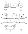
- the basic arrangement for this procedure is in Fig. 1 shown.
- a winding 13 of a generator 12 via a connection circuit 11 with a medium-voltage switch panel 14 is connected.
- An embodiment of the method according to the invention is characterized in that the connection takes place when the medium voltage passes through its phase maximum.
- Another embodiment of the inventive method is characterized in that the temporal course of the medium voltage is sampled, that it is determined when the medium voltage assumes an excellent value, which is reached a fixed period of time before passing through the predetermined phase position, and that after the expiration of the fixed Time span the connection takes place.
- the excellent value of the medium voltage is a zero crossing.
- Another embodiment is characterized in that the circuit breaker has its own delay time, and that the fixed period of time is greater than the delay time of the circuit breaker.
- Another embodiment of the method according to the invention is characterized in that the circuit breaker of a medium-voltage switching field is used as the circuit breaker.
- Another embodiment of the method according to the invention is characterized in that a mean voltage of 6-10 kV is used.
- connection circuit for carrying out the method has medium-voltage connections for connecting the medium voltage and winding connections for connecting the inductive load, which are interconnected via a power switch, wherein between the medium-voltage terminals and the circuit breaker, a first voltage converter is arranged, the output of the first voltage converter to the Input of a zero-crossing detector is connected, and the zero-crossing detector via a subsequent delay circuit controls the power switch.
- connection circuit is characterized in that the delay time of the delay circuit is adjustable.
- connection circuit is characterized in that a control panel is provided, via which the zero-crossing detector and the delay circuit can be put into a standby state.
- the idea underlying the invention is to minimize, as a first approximation, the inrush currents which occur during the performance of high-flux measurements by closing the associated circuit breaker which connects the associated winding to the medium-voltage source at the right time.
- the phase maximum of the AC voltage of the medium-voltage source is taken as the correct time.
- connection circuit 11 has two medium-voltage terminals 15a and 15b on the input side, to which the medium voltage used is applied.
- the medium-voltage terminals 15a and 15b connecting lines run to two output winding terminals 21a and 21b to which a winding 13 (turns of a medium voltage cable wound through the stator bore) of the generator 12 to be tested is connected.
- a separator 19 is inserted, with the aid of which the winding terminals 21 a and 21 b can be de-energized and grounded.
- a power switch 17 is inserted, which controls the actual switch-on.
- the control of the circuit breaker 17 is carried out in accordance with the time course of the medium voltage terminals 15a and 15b lying medium voltage.
- This alternating voltage is tapped via a voltage converter 16 and the output signal of the voltage converter 16 is fed to a zero-crossing detector 22, which detects the zero crossings of the alternating voltage and transmits corresponding signals to a delay circuit 23.
- the time delayed detector signals are then used to control the power switch 17. So that one of the delayed detector signals close the power switch 17 can, must first be prepared by a control panel 24 from the zero crossing detector 22 and the delay circuit 23 by corresponding signals (enable command) on standby. Once this is done, the next following detector signal from the zero-crossing detector 22 is used after appropriate delay in the delay circuit 23 to turn on the power switch 17.
- a further voltage converter 18 arranged between the power switch 17 and the isolator 19 can serve to monitor the behavior of the output voltage during the switch-on.
- a current transformer 20 can be used to control the flowing current during the switch-on process.
- a setting mode first the power switch 17 and the disconnector 19 are opened.
- the circuit breaker 17 is then closed and at the same time voltage profiles of the converter voltages VT1 and VT2 are recorded in an oscilloscopic manner (see Fig. 3 ).
- the delay time in the delay circuit 23 is now set so that the sum of the set delay time (T1 in Fig. 4 ) and from the delay switch (T2 in Fig. 4 ) Is just so large that the AC voltage then applied to the winding terminals 21 a and 21 b when the AC voltage reaches the maximum phase.
- connection circuit 11 can be used for carrying out the high-flow measurement of the generator.
- the disconnector 19 is permanently closed and from the control panel 24 is at the beginning of the test (time t1 in Fig. 4 ) is a ready signal to the zero-crossing detector 22 and the delay circuit 23. Is detected by the zero-crossing detector 22, the next zero crossing (time t2 in Fig. 4 ), the power switch 17 closes after passing the set delay time T1 and the inherent delay time T2 (time t3 in FIG Fig. 4 ), so that from there on the transducer voltage VT2 follows the course of the transducer voltage VT1.
- the flowchart comprises five sections FC1 to FC5.
- the first section FC1 designates the transition to the active test mode, in which the disconnector 19 is closed while the power switch 17 remains open. With a first command K1 then the devices 22 and 23 are put on standby. In the second section FC2, the next zero crossing is detected at the converter voltage VT1 of the voltage converter 16. In the third section FC3, the detector signal is subjected to a first time delay in the circuit 23. With a second command K2, the power switch 17 is commanded to turn on. After expiration of the inherent delay time of the circuit breaker (section FC4), the power switch 17 is actually closed (section FC5).
Landscapes
- Engineering & Computer Science (AREA)
- Power Engineering (AREA)
- Control Of Eletrric Generators (AREA)
- Electronic Switches (AREA)
- Tests Of Circuit Breakers, Generators, And Electric Motors (AREA)
Abstract
Description
Die vorliegende Erfindung bezieht sich auf das Gebiet der elektrischen Energieerzeugung. Sie betrifft ein Verfahren zum Zuschalten einer induktiven Last, insbesondere einer Wicklung durch die Statorbohrung eines Generators, an eine vorgegebene Wechselspannung im Mittelspannungsbereich gemäss dem Oberbegriff des Anspruchs 1. Sie betrifft weiterhin eine Anschlussschaltung zur Durchführung des Verfahrens.The present invention relates to the field of electric power generation. It relates to a method for connecting an inductive load, in particular a winding through the stator bore of a generator, to a predetermined AC voltage in the medium voltage range according to the preamble of claim 1. It further relates to a connection circuit for carrying out the method.
Für Hochfluss-Messungen am Stator eines Generators muss eine Mittelspannung von 6-10 kV an eine Spule beziehungsweise Wicklung angeschlossen und zugeschaltet werden, die aus 5-12 Windungen eines Mittelspannungskabels besteht, das durch die Statorbohrung hindurch gewickelt ist. Bisher wurde die Mittelspannung dadurch zugeschaltet, dass ein herkömmlicher Mittelspannungs-Leistungsschalter aus einem zugeordneten Schaltfeld geschlossen wurde. Die prinzipielle Anordnung für dieses Vorgehen ist in
Aufgrund einer zeitweisen Gleichstromkomponente im Schaltstrom und der hohen magnetischen Remanenz des Statorkerns können dabei extrem hohe Einschaltströme auftreten. Hierdurch ergeben sich ernsthafte Probleme, den Schutzschalter geschlossen zu halten, wenn die Einschaltströme die Grenzwerte der Überstromauslöser im einspeisenden Mittelspannungs-Schaltfeld überschreiten.Due to a temporary DC component in the switching current and the high magnetic remanence of the stator core, extremely high inrush currents can occur. This poses serious problems in keeping the circuit breaker closed when the inrush currents exceed the limits of the overcurrent releases in the medium voltage feed-in panel.
Es ist daher Aufgabe der Erfindung, ein Verfahren zum Zuschalten einer solchen induktiven Last an eine Mittelspannung zu schaffen, welches die Nachteile bekannter Verfahren vermeidet und sich durch das Auftreten minimaler Einschaltströme auszeichnet, sowie eine Anschlussschaltung zur Durchführung des Verfahrens anzugeben.It is therefore an object of the invention to provide a method for connecting such an inductive load to a medium voltage, which avoids the disadvantages of known methods and is characterized by the occurrence of minimum inrush currents, and to provide a connection circuit for performing the method.
Die Aufgabe wird durch die Gesamtheit der Merkmale der Ansprüche 1 und 8 gelöst. Für die Erfindung wesentlich ist, dass zur Reduzierung des Einschaltstromes das Zuschalten dann erfolgt, wenn die Mittelspannung eine vorbestimmte Phasenlage durchläuft.The object is solved by the entirety of the features of claims 1 and 8. For the invention it is essential that the connection is made to reduce the inrush current when the medium voltage passes through a predetermined phase position.
Eine Ausgestaltung des Verfahrens nach der Erfindung ist dadurch gekennzeichnet, dass das Zuschalten dann erfolgt, wenn die Mittelspannung ihr Phasenmaximum durchläuft.An embodiment of the method according to the invention is characterized in that the connection takes place when the medium voltage passes through its phase maximum.
Eine andere Ausgestaltung des erfindungsgemässen Verfahrens ist dadurch gekennzeichnet, dass der zeitliche Verlauf der Mittelspannung abgetastet wird, dass festgestellt wird, wann die Mittelspannung einen ausgezeichneten Wert annimmt, der eine feste Zeitspanne vor dem Durchlaufen der vorbestimmten Phasenlage erreicht wird, und dass nach Ablauf der festen Zeitspanne das Zuschalten erfolgt.Another embodiment of the inventive method is characterized in that the temporal course of the medium voltage is sampled, that it is determined when the medium voltage assumes an excellent value, which is reached a fixed period of time before passing through the predetermined phase position, and that after the expiration of the fixed Time span the connection takes place.
Insbesondere ist der ausgezeichnete Wert der Mittelspannung ein Nulldurchgang.In particular, the excellent value of the medium voltage is a zero crossing.
Eine andere Ausgestaltung zeichnet sich dadurch aus, dass der Leistungsschalter eine ihm eigene Verzögerungszeit aufweist, und dass die feste Zeitspanne grösser gewählt ist als die Verzögerungszeit des Schutzschalters.Another embodiment is characterized in that the circuit breaker has its own delay time, and that the fixed period of time is greater than the delay time of the circuit breaker.
Eine andere Ausgestaltung des erfindungsgemässen Verfahrens ist dadurch gekennzeichnet, dass als Leistungsschalter der Leistungsschalter eines Mittelspannungs-Schaltfeldes verwendet wird.Another embodiment of the method according to the invention is characterized in that the circuit breaker of a medium-voltage switching field is used as the circuit breaker.
Eine andere Ausgestaltung des erfindungsgemässen Verfahrens ist dadurch gekennzeichnet, dass eine Mittelspannung von 6-10 kV verwendet wird.Another embodiment of the method according to the invention is characterized in that a mean voltage of 6-10 kV is used.
Die erfindungsgemässe Anschlussschaltung zur Durchführung des Verfahrens weist Mittelspannungsanschlüsse zum Anschluss der Mittelspannung sowie Wicklungsanschlüsse zum Anschluss der induktiven Last auf, die untereinander über einen Leistungsschalter verbunden sind, wobei zwischen den Mittelspannungsanschlüssen und dem Leistungsschalter ein erster Spannungswandler angeordnet ist, der Ausgang des ersten Spannungswandlers an den Eingang eines Nulldurchgangs-Detektors angeschlossen ist, und der Nulldurchgangs-Detektor über eine nachfolgende Verzögerungsschaltung den Leistungsschalter steuert.The connection circuit according to the invention for carrying out the method has medium-voltage connections for connecting the medium voltage and winding connections for connecting the inductive load, which are interconnected via a power switch, wherein between the medium-voltage terminals and the circuit breaker, a first voltage converter is arranged, the output of the first voltage converter to the Input of a zero-crossing detector is connected, and the zero-crossing detector via a subsequent delay circuit controls the power switch.
Eine Ausgestaltung der Anschlussschaltung nach der Erfindung ist dadurch gekennzeichnet, dass die Verzögerungszeit der Verzögerungsschaltung einstellbar ist.An embodiment of the connection circuit according to the invention is characterized in that the delay time of the delay circuit is adjustable.
Eine andere Ausgestaltung der Anschlussschaltung ist dadurch gekennzeichnet, dass ein Steuerpult vorgesehen ist, über welches der Nulldurchgangs-Detektor und die Verzögerungsschaltung in einen Bereitschaftszustand versetzbar sind.Another embodiment of the connection circuit is characterized in that a control panel is provided, via which the zero-crossing detector and the delay circuit can be put into a standby state.
Die Erfindung soll nachfolgend anhand von Ausführungsbeispielen im Zusammenhang mit der Zeichnung näher erläutert werden. Es zeigen
- Fig. 1
- das stark vereinfachte Schaltbild einer Messanordnung für die Hochflussmessung am Stator eines Generators;
- Fig. 2
- den Aufbau einer Anschlussschaltung für eine Messanordnung nach
Fig. 1 gemäss einem Ausführungsbeispiel der Erfindung; - Fig. 3
- den zeitlichen Verlauf der gemessenen Spannungen vor und hinter dem ersten Schutzschalter aus
Fig. 2 ; - Fig. 4
- im Spannungs-Zeit-Diagramm den Ablauf des Zuschaltvorgangs gemäss einem Ausführungsbeispiel des erfindungsgemässen Verfahrens; und
- Fig. 5
- das Flussdiagramm des Zuschaltvorgangs aus
Fig. 4 .
- Fig. 1
- the greatly simplified circuit diagram of a measuring arrangement for high-flow measurement on the stator of a generator;
- Fig. 2
- the structure of a connection circuit for a measuring arrangement according to
Fig. 1 according to an embodiment of the invention; - Fig. 3
- the time course of the measured voltages before and after the first circuit breaker
Fig. 2 ; - Fig. 4
- in the voltage-time diagram, the sequence of the connection operation according to an embodiment of the inventive method; and
- Fig. 5
- the flowchart of the connection process off
Fig. 4 ,
Die der Erfindung zu Grunde liegende Idee besteht darin, die Einschaltströme, die während der Durchführung von Hochfluss-Messungen auftreten, in erster Näherung dadurch zu minimieren, dass der zugehörige Leistungsschalter, der die zugehörige Wicklung mit der Mittelspannungsquelle verbindet, zum richtigen Zeitpunkt geschlossen wird. Als richtiger Zeitpunkt wird insbesondere das Phasenmaximum der Wechselspannung der Mittelspannungsquelle genommen.The idea underlying the invention is to minimize, as a first approximation, the inrush currents which occur during the performance of high-flux measurements by closing the associated circuit breaker which connects the associated winding to the medium-voltage source at the right time. In particular, the phase maximum of the AC voltage of the medium-voltage source is taken as the correct time.
In
Zwischen dem Trenner 19 und den Mittelspannungsanschlüssen 15a und 15b ist ein Leistungsschalter 17 eingefügt, der den eigentlichen Einschaltvorgang steuert. Die Steuerung des Leistungsschalters 17 erfolgt nach Massgabe des zeitlichen Verlaufs der an den Mittelspannungsanschlüssen 15a und 15b liegenden Mittelspannung. Diese Wechselspannung wird über einen Spannungswandler 16 abgegriffen und das Ausgangssignal des Spannungswandlers 16 einem Nulldurchgangs-Detektor 22 zugeführt, der die Nulldurchgänge der Wechselspannung detektiert und entsprechende Signale an eine Verzögerungsschaltung 23 weitergibt. Die zeitlich verzögerten Detektorsignale werden dann zur Steuerung des Leistungsschalters 17 verwendet. Damit eines der zeitlich verzögerten Detektorsignale den Leistungsschalter 17 schliessen kann, müssen zunächst von einem Steuerpult 24 aus der Nulldurchgangs-Detektor 22 und die Verzögerungsschaltung 23 durch entsprechende Signale (enable command) in Bereitschaft versetzt werden. Ist dies geschehen, wird das nächstfolgende Detektorsignal aus dem Nulldurchgangs-Detektor 22 nach entsprechender Verzögerung in der Verzögerungsschaltung 23 zum Einschalten des Leistungsschalters 17 benutzt.Between the
Ein zwischen dem Leistungsschalter 17 und dem Trenner 19 angeordneter weiterer Spannungswandler 18 kann dazu dienen, das Verhalten der Ausgangsspannung während des Einschaltens zu überwachen. Zusätzlich kann ein Stromwandler 20 zur Kontrolle des fliessenden Stromes während des Einschaltvorgangs verwendet werden.A
Die mit den beiden Spannungswandlern 16 und 18 abgenommenen Spannungen VT1 und VT2 haben beim Einschalten die in
In einem Einstellmodus sind zunächst der Leistungsschalter 17 und der Trenner 19 geöffnet. Es wird dann der Leistungsschalter 17 geschlossen und dabei werden gleichzeitig Spannungsverläufe der Wandlerspannungen VT1 und VT2 oszillographisch aufgenommen (siehe
Ist diese Einstellung der Verzögerungszeit vorgenommen worden, kann die Anschlussschaltung 11 für die Durchführung der Hochflussmessung des Generators eingesetzt werden. Der Trenner 19 wird dazu dauerhaft geschlossen und vom Steuerpult 24 ergeht zu Beginn des Tests (Zeitpunkt t1 in
Das entsprechende Flussdiagramm dieses Ablaufs ist in
- 1010
- Messanordnungmeasuring arrangement
- 1111
- Anschlussschaltungconnection circuit
- 1212
- Generatorgenerator
- 1313
- Wicklung (Windungen eines Mittelspannungskabels durch die Statorbohrung)Winding (windings of a medium voltage cable through the stator bore)
- 1414
- Mittelspannungs-SchaltfeldMedium voltage switchgear panel
- 15a,b15a, b
- Mittelspannungsanschluss (Einspeisung)Medium voltage connection (supply)
- 16,1816.18
- SpannungswandlerDC converter
- 1717
- Leistungsschalterbreakers
- 1919
- Trenner (mit Erdungsstellung)Disconnector (with earthing position)
- 2020
- StromwandlerPower converter
- 21 a,b21 a, b
- Wicklungsanschlusswinding connection
- 2222
- Nulldurchgangs-DetektorZero crossing detector
- 2323
- Verzögerungsschaltungdelay circuit
- 2424
- Steuerpultcontroller
- VT1, VT2VT1, VT2
- Wandlerspannungvoltage converter
- t1,t2,t3t1, t2, t3
- Zeitpunkttime
- T1,2T1,2
- VerzögerungszeitDelay Time
- FC1-FC5FC1-FC5
- Flussdiagramm-AbschnittFlowchart-section
- K1,2K1,2
- Befehlcommand
Claims (10)
Applications Claiming Priority (1)
| Application Number | Priority Date | Filing Date | Title |
|---|---|---|---|
| DE201010044600 DE102010044600A1 (en) | 2010-09-07 | 2010-09-07 | Method for connecting an inductive load and connection circuit for carrying out the method |
Publications (2)
| Publication Number | Publication Date |
|---|---|
| EP2426689A2 true EP2426689A2 (en) | 2012-03-07 |
| EP2426689A3 EP2426689A3 (en) | 2013-03-06 |
Family
ID=44763825
Family Applications (1)
| Application Number | Title | Priority Date | Filing Date |
|---|---|---|---|
| EP20110178297 Withdrawn EP2426689A3 (en) | 2010-09-07 | 2011-08-22 | Method for connecting an inductive load and connecting circuit for carrying out the method |
Country Status (7)
| Country | Link |
|---|---|
| US (1) | US20120056496A1 (en) |
| EP (1) | EP2426689A3 (en) |
| JP (1) | JP2012080759A (en) |
| KR (1) | KR20120025436A (en) |
| CN (1) | CN102403841A (en) |
| CA (1) | CA2751768A1 (en) |
| DE (1) | DE102010044600A1 (en) |
Families Citing this family (4)
| Publication number | Priority date | Publication date | Assignee | Title |
|---|---|---|---|---|
| EP2608357B1 (en) * | 2011-12-19 | 2014-07-23 | Vetco Gray Controls Limited | Protecting against transients in a communication system |
| KR101723463B1 (en) * | 2015-05-28 | 2017-04-07 | 창신정보통신(주) | Multi-tap able to control on/off timing of output power of each power socket based on load type |
| JP7188259B2 (en) * | 2019-04-22 | 2022-12-13 | 株式会社ジェイテクト | Signal input device and signal detection method |
| CN112083231B (en) * | 2020-08-21 | 2023-04-25 | 中国大唐集团科学技术研究院有限公司西北电力试验研究院 | Generator stator core loss test device capable of reducing closing impact current |
Family Cites Families (9)
| Publication number | Priority date | Publication date | Assignee | Title |
|---|---|---|---|---|
| DE366854C (en) * | 1923-01-12 | Aeg | Device for connecting ferrous coils to alternating current voltages | |
| DE1082322B (en) * | 1954-02-22 | 1960-05-25 | Koch & Sterzel Kommanditgesell | Device for switching on or off a z. B. a transformer, in particular Roentgen transformer, containing AC circuit |
| DE2530047C3 (en) * | 1975-07-04 | 1979-06-21 | Siemens Ag, 1000 Berlin Und 8000 Muenchen | Arrangement for connecting transformers, in particular no-load transformers, to an AC voltage source |
| US4370564A (en) * | 1980-06-04 | 1983-01-25 | Ricoh Company, Ltd. | AC Switching device |
| AT384502B (en) * | 1985-09-10 | 1987-11-25 | Sprecher & Schuh Ag | DEVICE FOR THE CONTROLLED SWITCHING ON AND / OR SWITCHING OFF OF INDUCTIVE AND CAPACITIVE ELEMENTS IN THE HIGH VOLTAGE NETWORK |
| DE3614057A1 (en) * | 1986-04-25 | 1987-10-29 | Heidelberger Druckmasch Ag | METHOD AND CIRCUIT ARRANGEMENT FOR SWITCHING ON AN INDUCTIVITY WITH REMANENCE |
| JP2892717B2 (en) * | 1989-11-15 | 1999-05-17 | 株式会社日立製作所 | Power switching controller |
| GB0421443D0 (en) * | 2004-09-27 | 2004-10-27 | Unsworth Peter | Point on wave (pow) control for motor starting and switching |
| JP5248269B2 (en) * | 2008-10-31 | 2013-07-31 | 株式会社東芝 | Circuit breaker switching control device and circuit breaker switching control system |
-
2010
- 2010-09-07 DE DE201010044600 patent/DE102010044600A1/en not_active Withdrawn
-
2011
- 2011-08-22 EP EP20110178297 patent/EP2426689A3/en not_active Withdrawn
- 2011-08-26 US US13/218,668 patent/US20120056496A1/en not_active Abandoned
- 2011-09-06 CA CA 2751768 patent/CA2751768A1/en not_active Abandoned
- 2011-09-06 CN CN2011102766100A patent/CN102403841A/en active Pending
- 2011-09-06 KR KR20110090233A patent/KR20120025436A/en not_active Application Discontinuation
- 2011-09-06 JP JP2011193631A patent/JP2012080759A/en not_active Withdrawn
Non-Patent Citations (1)
| Title |
|---|
| None |
Also Published As
| Publication number | Publication date |
|---|---|
| US20120056496A1 (en) | 2012-03-08 |
| KR20120025436A (en) | 2012-03-15 |
| EP2426689A3 (en) | 2013-03-06 |
| CA2751768A1 (en) | 2012-03-07 |
| CN102403841A (en) | 2012-04-04 |
| DE102010044600A1 (en) | 2012-03-08 |
| JP2012080759A (en) | 2012-04-19 |
Similar Documents
| Publication | Publication Date | Title |
|---|---|---|
| EP2282399B1 (en) | Static converter and method for starting the converter | |
| DE102011083514A1 (en) | DC circuit breaker | |
| EP3510618A1 (en) | Circuit breaker | |
| EP3576284A1 (en) | Electrical coupling of a first electrical network with a second electric network | |
| EP2426689A2 (en) | Method for connecting an inductive load and connecting circuit for carrying out the method | |
| DE102008024348B4 (en) | Method for reducing pulsed earth currents on a large electric device and compensating circuit for earth current displacement | |
| EP1070376A1 (en) | Device and method for supplying an electric load with electric energy | |
| EP1475645A1 (en) | Synthetic testing circuit for high voltage alternating current circuit breakers | |
| WO2016026524A1 (en) | Method for interrupting an electric current in a dc line and application of said method | |
| WO2014075740A1 (en) | Transformation apparatus | |
| AT509837B1 (en) | APPARATUS FOR ERROR CURRENT REDUCTION | |
| DE102011005905A1 (en) | Switch for a transmission line for high voltage direct current | |
| WO2015169692A2 (en) | System and method for providing reactive power | |
| EP3080822B1 (en) | Device and method for reducing a magnetic unidirectional flux component in the core of a three-phase transformer | |
| DE202012001061U1 (en) | Test device for generating an overvoltage | |
| DE19903131A1 (en) | Method for connecting a transformer to an AC voltage network and circuit arrangement for carrying out the method | |
| Hashem et al. | Attenuation of Transformer Inrush Current Using Controlled Switching System on Delta-Star Transformer | |
| EP3262664B1 (en) | Method for changing the active number of turns of a control winding in an electric system, and electric system comprising a control winding | |
| AT515818A1 (en) | Method and system for testing a substation for power transmission systems | |
| DE112014006555B4 (en) | commutation circuit | |
| DE102012221952A1 (en) | Method for suppressing or interrupting arc in switch after opening, involves passing supply current in same direction as previous current between return path and infeed node through supply line | |
| EP3402062B1 (en) | Connection of at least two modular multilevel converters | |
| EP2274758A1 (en) | Method for determining a switching time of an electrical switching device | |
| WO1997006589A1 (en) | Thyristor switched capacitor bank | |
| DE102010034905A1 (en) | High-voltage electric energy supply devices e.g. sea-side converter stations, for use in high-voltage direct current power transmission system, have two three-phase transformers connected in parallel with each other |
Legal Events
| Date | Code | Title | Description |
|---|---|---|---|
| AK | Designated contracting states |
Kind code of ref document: A2 Designated state(s): AL AT BE BG CH CY CZ DE DK EE ES FI FR GB GR HR HU IE IS IT LI LT LU LV MC MK MT NL NO PL PT RO RS SE SI SK SM TR |
|
| AX | Request for extension of the european patent |
Extension state: BA ME |
|
| PUAI | Public reference made under article 153(3) epc to a published international application that has entered the european phase |
Free format text: ORIGINAL CODE: 0009012 |
|
| PUAL | Search report despatched |
Free format text: ORIGINAL CODE: 0009013 |
|
| AK | Designated contracting states |
Kind code of ref document: A3 Designated state(s): AL AT BE BG CH CY CZ DE DK EE ES FI FR GB GR HR HU IE IS IT LI LT LU LV MC MK MT NL NO PL PT RO RS SE SI SK SM TR |
|
| AX | Request for extension of the european patent |
Extension state: BA ME |
|
| RIC1 | Information provided on ipc code assigned before grant |
Ipc: H01H 33/59 20060101AFI20130128BHEP Ipc: H02H 9/00 20060101ALI20130128BHEP Ipc: H01H 9/56 20060101ALI20130128BHEP |
|
| 17P | Request for examination filed |
Effective date: 20130821 |
|
| RBV | Designated contracting states (corrected) |
Designated state(s): AL AT BE BG CH CY CZ DE DK EE ES FI FR GB GR HR HU IE IS IT LI LT LU LV MC MK MT NL NO PL PT RO RS SE SI SK SM TR |
|
| STAA | Information on the status of an ep patent application or granted ep patent |
Free format text: STATUS: THE APPLICATION IS DEEMED TO BE WITHDRAWN |
|
| 18D | Application deemed to be withdrawn |
Effective date: 20160301 |