EP2426828A2 - Transmission power control method for a wireless communication system - Google Patents
Transmission power control method for a wireless communication system Download PDFInfo
- Publication number
- EP2426828A2 EP2426828A2 EP11177310A EP11177310A EP2426828A2 EP 2426828 A2 EP2426828 A2 EP 2426828A2 EP 11177310 A EP11177310 A EP 11177310A EP 11177310 A EP11177310 A EP 11177310A EP 2426828 A2 EP2426828 A2 EP 2426828A2
- Authority
- EP
- European Patent Office
- Prior art keywords
- signal
- transmission power
- station
- wireless communication
- propagation path
- Prior art date
- Legal status (The legal status is an assumption and is not a legal conclusion. Google has not performed a legal analysis and makes no representation as to the accuracy of the status listed.)
- Granted
Links
Images


Classifications
-
- H—ELECTRICITY
- H04—ELECTRIC COMMUNICATION TECHNIQUE
- H04W—WIRELESS COMMUNICATION NETWORKS
- H04W52/00—Power management, e.g. TPC [Transmission Power Control], power saving or power classes
- H04W52/04—TPC
- H04W52/18—TPC being performed according to specific parameters
- H04W52/24—TPC being performed according to specific parameters using SIR [Signal to Interference Ratio] or other wireless path parameters
- H04W52/243—TPC being performed according to specific parameters using SIR [Signal to Interference Ratio] or other wireless path parameters taking into account interferences
-
- H—ELECTRICITY
- H04—ELECTRIC COMMUNICATION TECHNIQUE
- H04W—WIRELESS COMMUNICATION NETWORKS
- H04W52/00—Power management, e.g. TPC [Transmission Power Control], power saving or power classes
- H04W52/04—TPC
- H04W52/18—TPC being performed according to specific parameters
- H04W52/24—TPC being performed according to specific parameters using SIR [Signal to Interference Ratio] or other wireless path parameters
- H04W52/242—TPC being performed according to specific parameters using SIR [Signal to Interference Ratio] or other wireless path parameters taking into account path loss
-
- H—ELECTRICITY
- H04—ELECTRIC COMMUNICATION TECHNIQUE
- H04W—WIRELESS COMMUNICATION NETWORKS
- H04W52/00—Power management, e.g. TPC [Transmission Power Control], power saving or power classes
- H04W52/04—TPC
- H04W52/18—TPC being performed according to specific parameters
- H04W52/24—TPC being performed according to specific parameters using SIR [Signal to Interference Ratio] or other wireless path parameters
- H04W52/247—TPC being performed according to specific parameters using SIR [Signal to Interference Ratio] or other wireless path parameters where the output power of a terminal is based on a path parameter sent by another terminal
-
- H—ELECTRICITY
- H04—ELECTRIC COMMUNICATION TECHNIQUE
- H04W—WIRELESS COMMUNICATION NETWORKS
- H04W52/00—Power management, e.g. TPC [Transmission Power Control], power saving or power classes
- H04W52/04—TPC
- H04W52/38—TPC being performed in particular situations
- H04W52/50—TPC being performed in particular situations at the moment of starting communication in a multiple access environment
-
- Y—GENERAL TAGGING OF NEW TECHNOLOGICAL DEVELOPMENTS; GENERAL TAGGING OF CROSS-SECTIONAL TECHNOLOGIES SPANNING OVER SEVERAL SECTIONS OF THE IPC; TECHNICAL SUBJECTS COVERED BY FORMER USPC CROSS-REFERENCE ART COLLECTIONS [XRACs] AND DIGESTS
- Y02—TECHNOLOGIES OR APPLICATIONS FOR MITIGATION OR ADAPTATION AGAINST CLIMATE CHANGE
- Y02D—CLIMATE CHANGE MITIGATION TECHNOLOGIES IN INFORMATION AND COMMUNICATION TECHNOLOGIES [ICT], I.E. INFORMATION AND COMMUNICATION TECHNOLOGIES AIMING AT THE REDUCTION OF THEIR OWN ENERGY USE
- Y02D30/00—Reducing energy consumption in communication networks
- Y02D30/70—Reducing energy consumption in communication networks in wireless communication networks
Definitions
- the present invention relates to a method for controlling wireless transmission power and a communication channel data rate in a wireless communication system, and particularly preferably applied to a mobile communication system.
- USP 5,559,790 Hitachi Ltd., "Spread Spectrum Communication System and Transmission Power Control Method therefor" discloses a technique as follows. That is, each mobile station measures the reception quality of a pilot signal transmitted with known power by a base station. On the basis of that measuring result, the mobile station transmits a transmission power control signal to the base station for requesting higher transmission power in the case where the reception quality is bad than in the case where the reception quality is good.
- the base station controls the transmission power of a signal sent to the mobile station, on the basis of the transmission power control signal.
- the signal reception quality from the base station is kept substantially constant in the mobile station.
- Each of these techniques is aimed at controlling received power or quality on the reception side to be constant. That is, in a transmission power control method using any of the aforementioned background-art techniques, the reception quality is made constant enough to prevent deterioration of reception quality caused by a gain variation in a propagation path or in-system interference caused by unnecessarily excessive transmission power.
- Means for solving the foregoing problems has a feature in that means for measuring a propagation path gain and reception quality and means for transmitting transmission power control information and reception quality information are provided in a first Wireless Communication Station, and means for receiving the aforementioned transmission power control information and the aforementioned reception quality information and means for controlling transmission power and a data rate are provided in a second Wireless Communication Station.
- the second Wireless Communication Station may include control means for making control to increase the transmission power of the second Wireless Communication Station when the propagation path gain becomes high, and to reduce the transmission power of the second Wireless Communication Station when the propagation path gain becomes low.
- the second Wireless Communication Station may include control means for making control to increase the data rate when the reception quality is good, and to reduce the data rate when the reception quality is not good.
- the transmission power is reduced when the propagation path gain is low, there may occur dispersion in quality of Received Data or omission in the Received Data.
- the dispersion or the omission may be remedied by powerful error correction codes represented by turbo codes.
- Fig. 1 is a graph showing an example of a time variation of a propagation path gain. Now, consider that the propagation path gain has a variation as shown in Fig. 1 . That is, consider a propagation path in which gains at time instants t1, t2, t3 and t4 are 2, 1, 1/3 and 2/3 respectively so that the average gain is 1.
- Fig. 2 is a graph showing an example of a time variation of noise power.
- Fig. 3 is a graph showing an example of a time variation of equivalent noise power at a transmitter. Assume that constant noise with power of 1 is added on the reception side as shown in Fig. 2 . This is equivalent to the case where noises of powers 1/2, 1, 3 and 3/2 are added on the transmission side at the time instants t1, t2, t3 and t4 respectively as shown in Fig. 3 . That is, a variation of the propagation path gain can be regarded as a variation of noise power equivalently.
- C designates the number of transmissible bits per second
- W designates the frequency band width
- S designates the signal power
- N designates the noise power
- log2(x) designates the logarithm of x to the base of 2.
- Ave(x) designates the time average of x . Accordingly, if S(t) is varied with time by power control, the communication channel capacity will vary.
- the transmission power is controlled to make the communication channel capacity as large as possible. Specifically, control is made as follows.
- N+S will be constant finally when all the power has been distributed.
- S will not be distributed at all to a period of time in which N is larger than the attained S+N. In such a state, the communication channel capacity will be largest.
- the real transmission power is set at 0 (that is, transmission is suspended) when S(t) ⁇ 0.
- P_const is increased, the average transmission power and the communication channel capacity will increase.
- P_const is reduced, the average transmission power and the communication channel capacity will decrease. Accordingly, it will go well if P_const is determined as a value with which a desired communication channel capacity can be obtained.
- Fig. 4 shows the concept of transmission power control.
- the portions surrounded by the thick lines designate signal powers while the portions surrounded by the thin lines designate noise powers. That is, the transmission powers at the time instants t1, t2, t3 and t4 are set at 11/6, 4/3, 0 and 5/6 respectively.
- Fig. 5 shows received power in which the result of the transmission power control in Fig. 4 is viewed on the reception side.
- the received powers at the time instants t1, t2, t3 and t4 are 11/3, 4/3, 0 and 5/9 respectively.
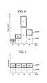
- Fig. 6 shows a comparative example in which control is made to make the transmission power proportional to the noise power in order to keep the received power or the reception quality constant. That is, the transmission powers at the time instants t1, t2, t3 and t4 are 1/3, 2/3, 2 and 1 respectively.
- Fig. 7 is a graph showing an example of a time variation of the received power based on the comparative example of Fig. 6 .
- the received powers at the time instants t1, t2, t3 and t4, in which the result of power distribution (transmission power control) in Fig. 6 is viewed on the reception side, are 2/3, 2/3, 2/3 and 2/3 respectively as shown in Fig. 7 .
- the present invention is compared with the background art as to the control of transmission power relative to a variation of the propagation path gain.
- the abscissa designates the propagation path gain
- the ordinate designates the transmission power as a result of transmission power control.
- the outline circles designate the present invention
- the outline diamonds designate the background art. That is, the channel gain has a relationship of inverse proportion to the transmission power in the background-art transmission power control, in which the transmission power is increased when the channel gain decreases, and the transmission power is reduced when the channel gain increases.
- the transmission power is reduced when the channel gain decreases, and the transmission power is increased when the channel gain increases.
- transmission power may be controlled by use of a function approximating the relationship between the propagation path gain and the transmission power shown in Fig. 8 . It is desired that the function has a positive slope as a whole. For example, substantially equal effect can be obtained even with a simple function by which the transmission power is made proportional to the propagation path gain.
- Fig. 9 is a graph showing a second example of a propagation path gain variation.
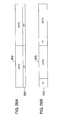
- Figs. 10A to 10D are graphs showing a second embodiment of transmission power control according to the present invention.
- the transmission power when the propagation path gain increases stepwise at the time instant t0 as shown in Fig. 9 , the transmission power also varies stepwise correspondingly as shown in Fig. 10A . In addition, when there occurs a control delay or the like, the transmission power varies with a certain rise time as shown in Fig. 10B .
- Co designates a constant. Consequently, the aforementioned power control is applied to a short-periodical variation of the communication channel while obtaining a substantially constant communication channel capacity regardless of a distance from the base station.
- the communication channel capacity varies with time. For this reason, it is therefore preferable that the bit rate is controlled so as to make communication at a high bit rate when the reception quality is good and the communication channel capacity is not lower than its average over a certain period of time, and so as to make communication conversely at a low bit rate when the reception quality is bad and the communication channel capacity is not higher than the average.
- the average bit rate can be enhanced without controlling the bit rate explicitly.
- this manner is suitable to a system required to have a fixed bit rate.
- the communication channel capacity is fixed by fixing the reception quality.
- the communication channel has a characteristic close to AWGN (Additive White Gaussian Noise). Therefore, error correction coding suitable for the AWGN communication channel is suitable.
- AWGN Additional White Gaussian Noise
- the reception quality has a large variation so that a part of Received Data is nearly omitted.
- time correlativity of the variation of the reception quality is eliminated by interleave, and further, powerfull error correction codes such as turbo codes or the like are applied so that Received Data poor in reception quality is remedied with Received Data good in reception quality by use of the redundancy of the error correction codes.
- LDPC Low Density Parity Check
- the remedy using error correction cannot be attained when the bad condition of the reception quality continues over a certain period of time (for example, a period of time corresponding to one coding unit of error correction codes or one interleave unit).
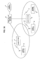
- Fig. 30 shows the system configuration according to the present invention.
- a plurality of mobile stations 3, 4 and 5 make communication with base stations 1 and 2 by wireless so that the base stations 1 and 2 establish communication of the aforementioned mobile stations with each other or with communication equipment belonging to a fixed network under the control of a base station control center 6.
- Fig. 11 shows the configuration of a reception-side Wireless Communication Station according to the present invention.
- Figs. 12A to 12C show format diagrams of first examples of a transmission signal multiplexing format of the transmission-side Wireless Communication Station according to the present invention.
- Fig. 13 shows the configuration of a transmission-side Wireless Communication Station according to the present invention.
- Figs. 14A and 14B show format diagrams of examples of a transmission signal multiplexing format of the reception-side Wireless Communication Station according to the present invention.
- one of Wireless Communication Stations whose transmission power and data rate are controlled according to the present invention is set as the transmission-side Wireless Communication Station, while the other is set as the reception-side Wireless Communication Station.
- the transmission-side Wireless Communication Station there is no preference as to which station, the mobile station or the base station, is the transmission-side Wireless Communication Station and which station is the reception-side Wireless Communication Station.
- the base station is set as the transmission-side Wireless Communication Station, transmission power control and bit rate control are carried out upon a downstream signal.
- transmission power control and bit rate control are carried out upon an upstream signal.
- a signal received through an antenna in Fig. 11 is converted into a baseband signal by a Radio Frequency Circuit 101.
- Demodulation processing such as detection and the like is carried out upon the baseband signal by a demodulator 102, and error correction is carried out on the demodulated baseband signal for every coding unit by a communication channel decoder 121.
- any missing data may be decoded without waiting for accumulation of all the data corresponding to one coding unit on the assumption that a signal whose power is zero has been received.
- decoding can be performed without waiting for accumulation of all the data corresponding to one coding unit.
- Decoding is carried out at any time in the course of accumulating the data corresponding to one coding unit.
- the result error-corrected by the communication channel decoder 121 is supplied to a reception quality judging portion 140, and errors are detected in an error detecting portion 115. Thus, the presence/absence of any error is made up as reception quality information.
- the aforementioned baseband signal is supplied to a power signal generating portion 105 so as to generate a transmission power control signal following the aforementioned power control algorithm.
- the reception quality information and the transmission power control signal are multiplexed by a multiplexer 109 together with a third pilot signal generated by a third pilot signal generating portion 130, and a data signal subjected to communication channel encoding in an error correction encoder 106 and an interleaver 107.
- the multiplexed signal has a format in Fig. 14A or 14B by way of example.
- the reference numeral 303 represents the data signal; 304, the power control signal; 305, the third pilot signal; and 306, the reception quality information signal.
- the widthwise direction designates time
- the lengthwise direction designates codes used for code division.
- Multiplexing is carried out in a multiplexing method such as time division multiplexing, code division multiplexing, or the like.
- the aforementioned multiplexed signal is modulated by a modulator 110, and sent to a wireless propagation path through the Radio Frequency Circuit 101.
- the signal sent from the reception-side Wireless Communication Station is received by the transmission-side Wireless Communication Station shown in Fig. 13 .
- the operations of members 101, 102, 103 and 104 are similar to those in the reception-side Wireless Communication Station.
- a transmission power control portion 111 extracts the aforementioned power control signal 304, and calculates transmission power corresponding to the extracted transmission power control signal 304.
- a reception quality signal extracting portion 141 extracts the aforementioned reception quality information signal 306, and notifies data rate control means 142 of the presence/absence of errors detected by the error detecting portion 115.
- transmission data encoded by a communication channel encoder 122 is accumulated for every coding unit. Then, the data rate is changed in accordance with the aforementioned information of the presence/absence of errors reported by the reception quality signal extracting portion 141, while the transmission data added with data for identifying the coding unit is outputted to a multiplexing portion 112.
- Fig. 31 shows an example of a processing flow carried out by the data rate control means 142.
- the data rate control means 142 divides the encoded transmission data into a plurality of blocks by coding unit, and transmits every block of the transmission data.
- the data rate control means 142 terminates the transmission.
- the data rate control means 142 transmits a block following the previously transmitted block.
- the data rate control means 142 repeats transmission from the start block again.
- the transmission data outputted from the data rate control means has a data rate necessary and sufficient for meeting the varying communication channel capacity.
- the transmission data outputted from the data rate control means 142 is multiplexed by the multiplexer 112 together with a second pilot signal generated by second pilot signal generating means 108, and supplied to transmission power varying means 113.
- the transmission power varying means 113 varies the signal amplitude correspondingly to the transmission power specified by the aforementioned transmission power control portion 111.
- the output of the transmission power varying means 113 is multiplexed by a multiplexer 115 together with a first pilot signal set to have a predetermined power by first pilot signal generating means 114, so that the multiplexed signal is formed into a format shown in anyone of Figs. 12A to 12C .
- the reference numeral 301 represents the first pilot signal; 302, the second pilot signal; and 303, the data signal.
- the first pilot signal 301 (P0) is transmitted by predetermined power without receiving the aforementioned power control from the transmission power control portion 111.
- the second pilot signal 302 is transmitted together with the data signal 303.
- the signal multiplexed in the format shown in any one of Figs. 12A to 12C is modulated in a modulator 110 and sent to the wireless propagation path through the Radio Frequency Circuit 101.
- Fig. 15 shows a block diagram of a first configuration example of a transmission power control signal generating portion according to the present invention.
- Fig. 16 shows a block diagram of a first configuration example of a transmission power control portion according to the present invention.
- the aforementioned transmission power signal generating portion 105 in the reception-side Wireless Communication Station and the aforementioned transmission power generating portion 111 in the transmission-side Wireless Communication Station are configured as shown in Figs. 15 and 16 , respectively.
- the transmission power signal generating portion in Fig. 15 separates the first pilot signal and the second pilot signal in first pilot signal separating means 201 and second pilot signal separating means 205 respectively.
- the transmission power signal generating portion generates a transmission power control signal 304 giving an instruction to reduce the transmission power when the current transmission power is larger, and an instruction to increase the transmission power when the current transmission power is smaller.
- the transmission power control portion in Fig. 16 extracts the aforementioned transmission power control signal 304, and increases/reduces the current transmission power in accordance with the transmission power control signal.
- noise power is obtained from the second pilot signal in Fig. 15 , it may be obtained from the first pilot signal (broken line).
- Fig. 32 shows a block diagram of a configuration example of an error correction encoder 106.
- encoding is performed with turbo codes.
- Input transmission data is encoded in accordance with data rate information, and an encoding result is outputted.
- the input transmission data is convolutionally encoded by a recursive convolutional encoder E1 (231) so as to be formed into a signal Y1.
- the data order of the aforementioned transmission data is changed by an interleaver 230. Then, the transmission data is convolutionally encoded by another recursive convolutional encoder E2 (232) so as to be formed into a signal Y2.
- original transmission data X (or U) and the signals Y1 and Y2 are integrated into one signal by a parallel-to-serial (P/S) converter 233, and an encoding result is outputted.
- P/S parallel-to-serial
- Fig. 33 shows a block diagram of a configuration example of an error correction decoder 104.
- Fig. 33 shows an error correction decoder supporting signals encoded by the turbo encoder in Fig. 32 .
- the error correction decoder carries out error correction decoding by iterative decoding in accordance with the reception signal information and the data rate information so as to output a decoding result U''.
- An input reception signal is separated into U', Y1' and Y2' in a serial-to-parallel (S/P) converter 234 by its operation reverse to that of the aforementioned parallel-to-serial (P/S) converter 233.
- S/P serial-to-parallel
- a soft decision decoder D1 (235) performs soft decision decoding processing corresponding to the aforementioned recursive convolutional encoder E1 (231) by use of the separated U' and Y1'.
- a decoding result by the soft decision decoder D1 (235) is supplied to a soft decision decoder D2 (238) through an interleaver 237.
- interleavers 236 and 237 follow the same order change rule as that of the interleaver 230 in Fig. 32 .
- the soft decision decoder D2 (238) carries out soft decision decoding using the output Y2' of the aforementioned serial-to-parallel (S/P) converter 234, the output of the aforementioned interleaver 236, and the output of the aforementioned interleaver 237, so that a decoding result is outputted.
- S/P serial-to-parallel
- the decoding result of the soft decision decoder D2 (238) is supplied to a deinterleaver 239 so as to be transposed in data order.
- the deinterleaver 239 operates to restore the data order by the operation reverse to those of the aforementioned interleavers 230, 236 and 237.
- the output of the deinterleaver 239 is supplied to the aforementioned soft decision decoder D1 (235) so as to be subjected to decoding processing again.
- the reception signal is passed through the soft decision decoders D1 (235) and D2 (238) repeatedly and alternately.
- precision of decoding is enhanced.
- one of the decoding results of the soft decision decoders D1 (235) and D2 (238) is outputted as a final decoding result.
- Figs. 32 and 33 show an example using turbo codes, as described previously, the error correction encoder and the error correction decoder may support error correction codes such as LDPC codes, product codes, or the like, capable of exhibiting high error correction capacity by iterative decoding processing.
- error correction codes such as LDPC codes, product codes, or the like
- Fig. 17 is a block diagram of a second configuration example of an encoder with a data rate control function according to the present invention.
- Fig. 18 is a block diagram of a second configuration example of a decoder with a data rate control function according to the present invention.
- the bit rate is controlled so as to make communication at a high bit rate on average when the communication channel capacity is not lower than the average over a certain period of time, and so as to make communication conversely at a low bit rate on average when the communication channel capacity is not higher than the average.
- a communication channel encoder and a communication channel decoder as shown in Figs. 17 and 18 respectively are used in place of the communication channel encoder 122 in Fig. 13 and the communication channel decoder 121 in Fig. 11 .
- an error correction encoder 106 for carrying out encoding at a data rate specified by a data rate instruction; a rate information generating portion 123 for generating data rate information, which is information about the data rate specified by the data rate instruction, and outputting the data rate information; an interleave portion 107 for carrying out interleave processing upon the output of the error correction encoder 106; and a multiplexing portion 124 for multiplexing the output of the interleave portion 107 and the output of the rate information generating portion 123.
- the communication channel decoder shown in Fig. 18 includes a rate information separating portion 125 for separating the data rate information from a received signal, a deinterleave portion 103 for deinterleaving the rest data from which the data rate information has been separated, and an error correction decoder 104 for decoding the output of the deinterleave portion in accordance with the separated data rate information.
- Fig. 19 shows an example of the configuration of the aforementioned transmission power control portion 105.
- a function operating portion 214 operates a function f(x) whose output increases as an input signal increases. Consequently, when the propagation path gain increases beyond its average value, a transmission power control signal giving an instruction to increase the transmission power is generated.
- Fig. 20 shows an example of the configuration simplified in the case where it can be granted that noise power is constant regardless of time.
- Figs. 21A and 21B , Figs. 22 to 25 , Figs. 26A and 26B , and Figs. 27 to 29 are diagrams showing other modified examples of the present invention.
- standardized transmission power S(t)/P0 may be obtained by the configuration shown in Fig. 22 so that, by use of this standardized transmission power S(t)/P0 as a transmission power control signal, S(t) can be obtained by the transmission power control portion shown in Fig. 23 .
- the configuration of Fig. 24 and the configuration of Fig. 25 may be used in place of the configuration of Fig. 22 and the configuration of Fig. 23 respectively.
- S(t) can be obtained by the transmission power control signal generating portion shown in Fig. 27 and the transmission power control portion shown in Fig. 16 .
- the configuration of Fig. 28 and the configuration of Fig. 29 may be used in place of the configuration of Fig. 27 and the configuration of Fig. 16 respectively.
Abstract
Description
- The present invention relates to a method for controlling wireless transmission power and a communication channel data rate in a wireless communication system, and particularly preferably applied to a mobile communication system.
- In wireless communication systems, there are known techniques for controlling transmission power of a Wireless Communication Station in order to obtain a desired reception quality. For example,
USP 5,267,262 , Qualcomm Inc., "Transmitter Power Control System" discloses a technique in a CDMA mobile communication system as follows. That is, signal received power from each mobile station is measured in a base station. When the measured signal received power is lower than a desired value, an instruction to increase transmission power is transmitted to the mobile station. When the measured signal received power is higher than the desired value, an instruction to reduce the transmission power is transmitted to the mobile station. The mobile station controls the transmission power in accordance with the aforementioned transmission power control instruction. Thus, the received power in the base station is kept substantially constant. - In addition,
USP 5,559,790 , Hitachi Ltd., "Spread Spectrum Communication System and Transmission Power Control Method therefor" discloses a technique as follows. That is, each mobile station measures the reception quality of a pilot signal transmitted with known power by a base station. On the basis of that measuring result, the mobile station transmits a transmission power control signal to the base station for requesting higher transmission power in the case where the reception quality is bad than in the case where the reception quality is good. The base station controls the transmission power of a signal sent to the mobile station, on the basis of the transmission power control signal. Thus, the signal reception quality from the base station is kept substantially constant in the mobile station. - Each of these techniques is aimed at controlling received power or quality on the reception side to be constant. That is, in a transmission power control method using any of the aforementioned background-art techniques, the reception quality is made constant enough to prevent deterioration of reception quality caused by a gain variation in a propagation path or in-system interference caused by unnecessarily excessive transmission power.
- However, assume that there is a fading which is a propagation path gain variation having a comparatively short period of time and generated as a mobile station moves. In such a case, when the background-art techniques are used, the transmission power becomes very high when the propagation path gain drops down instantaneously. Thus, average transmission power increases. The increase of the average transmission power increases mutual interference provided for the system as a whole, and results in lowering of communication throughput in the system as a whole. In addition, in a mobile station, the increase of the average transmission power increases power consumption so that the time allowed to talk becomes short.
- It is therefore a first object of the present invention to provide a transmission power control method for attaining a desired reception quality while preventing increase in average transmission power even when there occurs a propagation path gain variation having a comparatively short period of time.
- In addition, when the average transmission power is not increased, average received power is reduced. The deterioration of the reception quality (SN ratio or SNR) caused by the reduction results in lowering in the capacity of the communication channel. That is, the maximum data rate at which communication can be made is lowered. It is therefore a second object of the present invention to keep the communication channel capacity as large as possible even when there occurs a propagation path gain variation having a comparatively short period of time.
- In addition, when the communication channel capacity per time varies due to a variation of the propagation path gain, there is a problem that the time required for making communication for desired information varies so that stable communication quality cannot be obtained. It is therefore a third object of the present invention to provide stable communication quality even when the communication channel capacity per time varies.
- Means for solving the foregoing problems has a feature in that means for measuring a propagation path gain and reception quality and means for transmitting transmission power control information and reception quality information are provided in a first Wireless Communication Station, and means for receiving the aforementioned transmission power control information and the aforementioned reception quality information and means for controlling transmission power and a data rate are provided in a second Wireless Communication Station. The second Wireless Communication Station may include control means for making control to increase the transmission power of the second Wireless Communication Station when the propagation path gain becomes high, and to reduce the transmission power of the second Wireless Communication Station when the propagation path gain becomes low. In addition, the second Wireless Communication Station may include control means for making control to increase the data rate when the reception quality is good, and to reduce the data rate when the reception quality is not good. Further, if the transmission power is reduced when the propagation path gain is low, there may occur dispersion in quality of Received Data or omission in the Received Data. The dispersion or the omission may be remedied by powerful error correction codes represented by turbo codes.
- Other aspects of the present invention will be made clear in the following embodiments of the present invention.
-
-
Fig. 1 is a graph showing an example of a time variation of a propagation path gain. -
Fig. 2 is a graph showing an example of a time variation of noise power. -
Fig. 3 is a graph showing an example of a time variation of equivalent noise power at a transmitter. -
Fig. 4 is a graph showing an embodiment of transmission power control according to the present invention. -
Fig. 5 is a graph showing an example of a time variation of received power according to the present invention. -
Fig. 6 is a graph showing an example of transmission power control according to the background art. -
Fig. 7 is a graph showing an example of a time variation of received power according to the background art. -
Fig. 8 is a graph showing comparison of transmission power by transmission power control according to the present invention with that according to the background art. -
Fig. 9 is a graph showing a second example of a propagation path gain variation. -
Figs. 10A-10D are graphs showing a second embodiment of transmission power control according to the present invention. -
Fig. 11 is a block diagram of an example of configuration of a reception-side Wireless Communication Station according to the present invention. -
Figs. 12A-12C are format diagrams of first examples of a transmission signal multiplexing format in a transmission-side Wireless Communication Station according to the present invention. -
Fig. 13 is a block diagram showing a configuration of the transmission-side Wireless Communication Station according to the present invention. -
Figs. 14A and 14B are format diagrams of examples of a transmission signal multiplexing format in the reception-side Wireless Communication Station according to the present invention. -
Fig. 15 is a block diagram of a first configuration example of a transmission power control signal genrating portion according to the present invention. -
Fig. 16 is a block diagram of a first configuration example of a transmission power control portion according to the present invention. -
Fig. 17 is a block diagram of a second configuration example of an encoder with a data rate control function according to the present invention. -
Fig. 18 is a block diagram of a second configuration example of a decoder with a data rate control function according to the present invention. -
Fig. 19 is a block diagram of a second configuration example of a transmission power control signal generating portion according to the present invention. -
Fig. 20 is a block diagram of a third configuration example of a transmission power control signal generating portion according to the present invention. -
Figs. 21A and 21B are format diagrams of second examples of a transmission signal multiplexing format in the transmission-side Wireless Communication Station according to the present invention. -
Fig. 22 is a block diagram of a fourth configuration example of a transmission power control signal generating portion according to the present invention. -
Fig. 23 is a block diagram of a second configuration example of a transmission power control portion according to the present invention. -
Fig. 24 is a block diagram of a fifth configuration example of a transmission power control signal generating portion according to the present invention. -
Fig. 25 is a block diagram of a third configuration example of a transmission power control portion according to the present invention. -
Figs. 26A and 26B are format diagrams of third examples of a transmission signal multiplexing format in the transmission-side Wireless Communication Station according to the present invention. -
Fig. 27 is a block diagram of a sixth configuration example of a transmission power control signal generating portion according to the present invention. -
Fig. 28 is a block diagram of a seventh configuration example of a transmission power control signal generating portion according to the present invention. -
Fig. 29 is a block diagram of a fourth configuration example of a transmission power control portion according to the present invention. -
Fig. 30 is a system configuration diagram according to the present invention. -
Fig. 31 is a flow chart of an example of a flow of processing of data rate control means according to the present invention. -
Fig. 32 is a block diagram of a configuration example of an error correction encoder of a transmission-side Wireless Communication Station according to the present invention. -
Fig. 33 is a block diagram of a configuration example of an error correction decoder of a reception-side Wireless Communication Station according to the present invention. - First, description will be made on a power control algorithm according to the present invention.
-
Fig. 1 is a graph showing an example of a time variation of a propagation path gain. Now, consider that the propagation path gain has a variation as shown inFig. 1 . That is, consider a propagation path in which gains at time instants t1, t2, t3 and t4 are 2, 1, 1/3 and 2/3 respectively so that the average gain is 1. -
Fig. 2 is a graph showing an example of a time variation of noise power. -
Fig. 3 is a graph showing an example of a time variation of equivalent noise power at a transmitter. Assume that constant noise with power of 1 is added on the reception side as shown inFig. 2 . This is equivalent to the case where noises ofpowers 1/2, 1, 3 and 3/2 are added on the transmission side at the time instants t1, t2, t3 and t4 respectively as shown inFig. 3 . That is, a variation of the propagation path gain can be regarded as a variation of noise power equivalently. - On the other hand, it is known that capacity C of a communication channel is theoretically expressed by C=W log2 (1+S/N). Here, C designates the number of transmissible bits per second, W designates the frequency band width, S designates the signal power, N designates the noise power, and log2(x) designates the logarithm of x to the base of 2. Accordingly, the communication channel capacity in a propagation path varying with time as described above is expressed by C=Ave(W log2(1+S(t)/N(t))) where S(t) and N(t) designate signal power and noise power at a time instant t respectively. Here, Ave(x) designates the time average of x. Accordingly, if S(t) is varied with time by power control, the communication channel capacity will vary. In the present invention, the transmission power is controlled to make the communication channel capacity as large as possible. Specifically, control is made as follows.
- Now, consider S(t) that maximizes the communication channel capacity C on the assumption that the average transmission power, that is, the time average Ave(S(t)) of S(t) is constant. Since Ave(S(t)) is constant, if transmission power at one time instant is increased, transmission power at another time instant has to be reduced. Here, the increasing rate of C relative to a very small increase of S is expressed by dC/dS=W/log(2)/(N+S) on the basis of the aforementioned definitional expression of the communication channel capacity. Accordingly, when fixed power is distributed timewise, the communication channel capacity will be increased to a maximum if the transmission power is distributed to a minimum of N+S. If the transmission power is sequentially distributed thus to the minimum of N+S, N+S will be constant finally when all the power has been distributed. In addition, S will not be distributed at all to a period of time in which N is larger than the attained S+N. In such a state, the communication channel capacity will be largest.
- Here, assume that the noise power received by a receiver is expressed by a function Nr(t) of time, and the propagation path gain is expressed by a function g(t) of time. Then, equivalent noise power N(t) viewed on the transmitter side is expressed by:

- Accordingly, the aforementioned transmission power S(t) that maximizes the communication channel capacity satisfies the following condition:

(constant) - That is, it will go well if control is made to satisfy:

- Then, the real transmission power is set at 0 (that is, transmission is suspended) when S(t)<0. Incidentally, if P_const is increased, the average transmission power and the communication channel capacity will increase. On the contrary, if P_const is reduced, the average transmission power and the communication channel capacity will decrease. Accordingly, it will go well if P_const is determined as a value with which a desired communication channel capacity can be obtained.
-
Fig. 4 shows the concept of transmission power control. For example, on the assumption that the average transmission power is set at 1 under the variation of the propagation path gain shown inFig. 1 , the result of controlling the transmission power is shown inFig. 4 . In the drawing, the portions surrounded by the thick lines designate signal powers while the portions surrounded by the thin lines designate noise powers. That is, the transmission powers at the time instants t1, t2, t3 and t4 are set at 11/6, 4/3, 0 and 5/6 respectively. The average transmission power is expressed by:
-
Fig. 5 shows received power in which the result of the transmission power control inFig. 4 is viewed on the reception side. The received powers at the time instants t1, t2, t3 and t4 are 11/3, 4/3, 0 and 5/9 respectively. -
Fig. 6 shows a comparative example in which control is made to make the transmission power proportional to the noise power in order to keep the received power or the reception quality constant. That is, the transmission powers at the time instants t1, t2, t3 and t4 are 1/3, 2/3, 2 and 1 respectively. The average transmission power is expressed by:
-
Fig. 7 is a graph showing an example of a time variation of the received power based on the comparative example ofFig. 6 . The received powers at the time instants t1, t2, t3 and t4, in which the result of power distribution (transmission power control) inFig. 6 is viewed on the reception side, are 2/3, 2/3, 2/3 and 2/3 respectively as shown inFig. 7 . - In
Fig. 8 , the present invention is compared with the background art as to the control of transmission power relative to a variation of the propagation path gain. The abscissa designates the propagation path gain, and the ordinate designates the transmission power as a result of transmission power control. In the drawing, the outline circles designate the present invention, and the outline diamonds designate the background art. That is, the channel gain has a relationship of inverse proportion to the transmission power in the background-art transmission power control, in which the transmission power is increased when the channel gain decreases, and the transmission power is reduced when the channel gain increases. On the contrary, according to the present invention, the transmission power is reduced when the channel gain decreases, and the transmission power is increased when the channel gain increases. - In addition, the communication channel capacity attained by the transmission power control according to the present invention is expressed by:

- On the other hand, the communication channel capacity attained by the transmission power control according to the background art is expressed by:

- Hence, in the examples shown here, the communication channel capacity based on the power control according to the present invention increases to be 1.38 (=(1.02/0.737)) times as large as that in the background-art power control method. On the other hand, in order that the same communication channel capacity as the aforementioned communication channel capacity in the case where the present invention has been applied is attained by use of the background-art transmission power control system, S/N=1.028 is required because 1.02=log2(1+1.028). Thus, the average transmission power 1.54 (=1.028/(2/3)) times as large as S/N=2/3 attained by the aforementioned background-art transmission power control is required. Accordingly, according to the present invention, the transmission power for attaining the same communication channel capacity is reduced to 0.649 times as large as that in the case where the background art is used.
- Description has been made above on the transmission power control algorithm for maximizing the communication channel capacity theoretically. However, substantially equal effect can be obtained without following the aforementioned algorithm strictly. That is, transmission power may be controlled by use of a function approximating the relationship between the propagation path gain and the transmission power shown in
Fig. 8 . It is desired that the function has a positive slope as a whole. For example, substantially equal effect can be obtained even with a simple function by which the transmission power is made proportional to the propagation path gain. -
Fig. 9 is a graph showing a second example of a propagation path gain variation. -
Figs. 10A to 10D are graphs showing a second embodiment of transmission power control according to the present invention. - According to the algorithm for determining the transmission power:

- when the propagation path gain increases stepwise at the time instant t0 as shown in
Fig. 9 , the transmission power also varies stepwise correspondingly as shown inFig. 10A . In addition, when there occurs a control delay or the like, the transmission power varies with a certain rise time as shown inFig. 10B . - In the control of
Fig. 10A or 10B , the communication channel capacity increases when a mobile station is located in a place close to a base station having a high propagation path gain, and on the contrary the communication channel capacity decreases when the mobile station is located in a place distant from the base station. When such a difference is not preferable on the system design, practically, P_const is controlled comparatively slowly by use of the average gain and the average noise power in the current communication channel situation, for example, by:
- Here, Co designates a constant. Consequently, the aforementioned power control is applied to a short-periodical variation of the communication channel while obtaining a substantially constant communication channel capacity regardless of a distance from the base station.
- In this case, response to the aforementioned variation of the propagation path gain shown in
Fig. 9 is made so that transmission power as shown inFig. 10C or 10D is similar to the aforementioned transmission power inFig. 10A or 10B for a short period of time, whereafter the transmission power approaches gradually to transmission power canceling the variation of the propagation path gain in the same manner as that under the background-art power control. - According to the above power control, the communication channel capacity varies with time. For this reason, it is therefore preferable that the bit rate is controlled so as to make communication at a high bit rate when the reception quality is good and the communication channel capacity is not lower than its average over a certain period of time, and so as to make communication conversely at a low bit rate when the reception quality is bad and the communication channel capacity is not higher than the average.
- In addition, when the average times Ave(Nr(t)) and Ave(g(t)) used for calculating P_const are made consistent with the unit with which communication channel coding is executed, the average bit rate can be enhanced without controlling the bit rate explicitly. Thus, this manner is suitable to a system required to have a fixed bit rate.
- In the background-art power control, the communication channel capacity is fixed by fixing the reception quality. Thus, the communication channel has a characteristic close to AWGN (Additive White Gaussian Noise). Therefore, error correction coding suitable for the AWGN communication channel is suitable.
- On the other hand, in the aforementioned power control, the reception quality has a large variation so that a part of Received Data is nearly omitted.
- Accordingly, for a variation having a comparatively short period of time, it is preferable that time correlativity of the variation of the reception quality is eliminated by interleave, and further, powerfull error correction codes such as turbo codes or the like are applied so that Received Data poor in reception quality is remedied with Received Data good in reception quality by use of the redundancy of the error correction codes.
- It is also preferable to apply LDPC (Low Density Parity Check) codes, product codes, or the like, instead of turbo codes.
- More generally, it is preferable to apply error correction codes having dependency in which a large number of bits constituting a code word have been catenated complicatedly, and known to have a high error correction capacity when iterative decoding is applied to perform decoding again using a halfway result of decoding.
- In addition, the remedy using error correction cannot be attained when the bad condition of the reception quality continues over a certain period of time (for example, a period of time corresponding to one coding unit of error correction codes or one interleave unit).
- Description will be made below on the system and the apparatus configuration for carrying out the aforementioned algorithm.
-
Fig. 30 shows the system configuration according to the present invention. A plurality ofmobile stations base stations base stations -
Fig. 11 shows the configuration of a reception-side Wireless Communication Station according to the present invention. -
Figs. 12A to 12C show format diagrams of first examples of a transmission signal multiplexing format of the transmission-side Wireless Communication Station according to the present invention. -
Fig. 13 shows the configuration of a transmission-side Wireless Communication Station according to the present invention. -
Figs. 14A and 14B show format diagrams of examples of a transmission signal multiplexing format of the reception-side Wireless Communication Station according to the present invention. - Here, one of Wireless Communication Stations whose transmission power and data rate are controlled according to the present invention is set as the transmission-side Wireless Communication Station, while the other is set as the reception-side Wireless Communication Station. On the system configuration shown in
Fig. 30 , there is no preference as to which station, the mobile station or the base station, is the transmission-side Wireless Communication Station and which station is the reception-side Wireless Communication Station. When the base station is set as the transmission-side Wireless Communication Station, transmission power control and bit rate control are carried out upon a downstream signal. On the contrary, when the mobile station is set as the transmission-side Wireless Communication Station, transmission power control and bit rate control are carried out upon an upstream signal. - A signal received through an antenna in
Fig. 11 is converted into a baseband signal by aRadio Frequency Circuit 101. Demodulation processing such as detection and the like is carried out upon the baseband signal by ademodulator 102, and error correction is carried out on the demodulated baseband signal for every coding unit by acommunication channel decoder 121. - Incidentally, at the time of decoding in the
communication channel decoder 121, any missing data may be decoded without waiting for accumulation of all the data corresponding to one coding unit on the assumption that a signal whose power is zero has been received. Thus, decoding can be performed without waiting for accumulation of all the data corresponding to one coding unit. Decoding is carried out at any time in the course of accumulating the data corresponding to one coding unit. The result error-corrected by thecommunication channel decoder 121 is supplied to a receptionquality judging portion 140, and errors are detected in anerror detecting portion 115. Thus, the presence/absence of any error is made up as reception quality information. On the other hand, the aforementioned baseband signal is supplied to a powersignal generating portion 105 so as to generate a transmission power control signal following the aforementioned power control algorithm. The reception quality information and the transmission power control signal are multiplexed by amultiplexer 109 together with a third pilot signal generated by a third pilotsignal generating portion 130, and a data signal subjected to communication channel encoding in anerror correction encoder 106 and aninterleaver 107. The multiplexed signal has a format inFig. 14A or 14B by way of example. Thereference numeral 303 represents the data signal; 304, the power control signal; 305, the third pilot signal; and 306, the reception quality information signal. In the drawings, the widthwise direction designates time, and the lengthwise direction designates codes used for code division. Multiplexing is carried out in a multiplexing method such as time division multiplexing, code division multiplexing, or the like. The aforementioned multiplexed signal is modulated by amodulator 110, and sent to a wireless propagation path through theRadio Frequency Circuit 101. - The signal sent from the reception-side Wireless Communication Station is received by the transmission-side Wireless Communication Station shown in
Fig. 13 . The operations ofmembers power control portion 111 extracts the aforementionedpower control signal 304, and calculates transmission power corresponding to the extracted transmissionpower control signal 304. A reception qualitysignal extracting portion 141 extracts the aforementioned receptionquality information signal 306, and notifies data rate control means 142 of the presence/absence of errors detected by theerror detecting portion 115. In the data rate control means 142, transmission data encoded by acommunication channel encoder 122 is accumulated for every coding unit. Then, the data rate is changed in accordance with the aforementioned information of the presence/absence of errors reported by the reception qualitysignal extracting portion 141, while the transmission data added with data for identifying the coding unit is outputted to amultiplexing portion 112. -
Fig. 31 shows an example of a processing flow carried out by the data rate control means 142. In the flow of processing inFig. 31 , the data rate control means 142 divides the encoded transmission data into a plurality of blocks by coding unit, and transmits every block of the transmission data. When the data rate control means 142 is notified of no error, the data rate control means 142 terminates the transmission. When the data rate control means 142 is not notified of no error, the data rate control means 142 transmits a block following the previously transmitted block. When the data rate control means 142 is not notified of no error after finishing transmitting all the blocks, the data rate control means 142 repeats transmission from the start block again. Thus, the transmission data outputted from the data rate control means has a data rate necessary and sufficient for meeting the varying communication channel capacity. The transmission data outputted from the data rate control means 142 is multiplexed by themultiplexer 112 together with a second pilot signal generated by second pilot signal generating means 108, and supplied to transmission power varying means 113. The transmission power varying means 113 varies the signal amplitude correspondingly to the transmission power specified by the aforementioned transmissionpower control portion 111. The output of the transmission power varying means 113 is multiplexed by amultiplexer 115 together with a first pilot signal set to have a predetermined power by first pilot signal generating means 114, so that the multiplexed signal is formed into a format shown in anyone ofFigs. 12A to 12C . InFigs. 12A to 12C , thereference numeral 301 represents the first pilot signal; 302, the second pilot signal; and 303, the data signal. - As shown in
Figs. 12A to 12C , various multiplexing formats can be adopted. In addition, the first pilot signal 301 (P0) is transmitted by predetermined power without receiving the aforementioned power control from the transmissionpower control portion 111. On the other hand, while receiving the aforementioned power control, thesecond pilot signal 302 is transmitted together with the data signal 303. The signal multiplexed in the format shown in any one ofFigs. 12A to 12C is modulated in amodulator 110 and sent to the wireless propagation path through theRadio Frequency Circuit 101. -
Fig. 15 shows a block diagram of a first configuration example of a transmission power control signal generating portion according to the present invention. -
Fig. 16 shows a block diagram of a first configuration example of a transmission power control portion according to the present invention. - For example, the aforementioned transmission power
signal generating portion 105 in the reception-side Wireless Communication Station and the aforementioned transmissionpower generating portion 111 in the transmission-side Wireless Communication Station are configured as shown inFigs. 15 and16 , respectively. The transmission power signal generating portion inFig. 15 separates the first pilot signal and the second pilot signal in first pilot signal separating means 201 and second pilot signal separating means 205 respectively. The transmission power signal generating portion uses acomparator 211 to judge whether current transmission power is larger or smaller than the transmission power satisfying:
when:
- Then, the transmission power signal generating portion generates a transmission
power control signal 304 giving an instruction to reduce the transmission power when the current transmission power is larger, and an instruction to increase the transmission power when the current transmission power is smaller. Accordingly, the transmission power control portion inFig. 16 extracts the aforementioned transmissionpower control signal 304, and increases/reduces the current transmission power in accordance with the transmission power control signal. Incidentally, although noise power is obtained from the second pilot signal inFig. 15 , it may be obtained from the first pilot signal (broken line). -
Fig. 32 shows a block diagram of a configuration example of anerror correction encoder 106. - In
Fig. 32 , encoding is performed with turbo codes. Input transmission data is encoded in accordance with data rate information, and an encoding result is outputted. - The input transmission data is convolutionally encoded by a recursive convolutional encoder E1 (231) so as to be formed into a signal Y1.
- In addition, the data order of the aforementioned transmission data is changed by an
interleaver 230. Then, the transmission data is convolutionally encoded by another recursive convolutional encoder E2 (232) so as to be formed into a signal Y2. - After that, original transmission data X (or U) and the signals Y1 and Y2 are integrated into one signal by a parallel-to-serial (P/S)
converter 233, and an encoding result is outputted. -
Fig. 33 shows a block diagram of a configuration example of anerror correction decoder 104. -
Fig. 33 shows an error correction decoder supporting signals encoded by the turbo encoder inFig. 32 . The error correction decoder carries out error correction decoding by iterative decoding in accordance with the reception signal information and the data rate information so as to output a decoding result U''. - An input reception signal is separated into U', Y1' and Y2' in a serial-to-parallel (S/P)
converter 234 by its operation reverse to that of the aforementioned parallel-to-serial (P/S)converter 233. - A soft decision decoder D1 (235) performs soft decision decoding processing corresponding to the aforementioned recursive convolutional encoder E1 (231) by use of the separated U' and Y1'.
- A decoding result by the soft decision decoder D1 (235) is supplied to a soft decision decoder D2 (238) through an
interleaver 237. - On the other hand, the data order of the output U' of the aforementioned serial-to-parallel (S/P)
converter 234 is changed by aninterleaver 236, and the transposed data is supplied to the aforementioned soft decision decoder D2 (238). - Here, the
interleavers interleaver 230 inFig. 32 . - The soft decision decoder D2 (238) carries out soft decision decoding using the output Y2' of the aforementioned serial-to-parallel (S/P)
converter 234, the output of theaforementioned interleaver 236, and the output of theaforementioned interleaver 237, so that a decoding result is outputted. - The decoding result of the soft decision decoder D2 (238) is supplied to a
deinterleaver 239 so as to be transposed in data order. - The
deinterleaver 239 operates to restore the data order by the operation reverse to those of theaforementioned interleavers - The output of the
deinterleaver 239 is supplied to the aforementioned soft decision decoder D1 (235) so as to be subjected to decoding processing again. - In such a manner, the reception signal is passed through the soft decision decoders D1 (235) and D2 (238) repeatedly and alternately. Thus, precision of decoding is enhanced.
- After decoding is performed a sufficient number of times, one of the decoding results of the soft decision decoders D1 (235) and D2 (238) is outputted as a final decoding result.
- Although
Figs. 32 and33 show an example using turbo codes, as described previously, the error correction encoder and the error correction decoder may support error correction codes such as LDPC codes, product codes, or the like, capable of exhibiting high error correction capacity by iterative decoding processing. -
Fig. 17 is a block diagram of a second configuration example of an encoder with a data rate control function according to the present invention. -
Fig. 18 is a block diagram of a second configuration example of a decoder with a data rate control function according to the present invention. - In the above embodiment, as described previously, it is preferable that the bit rate is controlled so as to make communication at a high bit rate on average when the communication channel capacity is not lower than the average over a certain period of time, and so as to make communication conversely at a low bit rate on average when the communication channel capacity is not higher than the average. To this end, it will go well if a communication channel encoder and a communication channel decoder as shown in
Figs. 17 and 18 respectively are used in place of thecommunication channel encoder 122 inFig. 13 and thecommunication channel decoder 121 inFig. 11 . The communication channel encoder shown inFig. 17 includes: anerror correction encoder 106 for carrying out encoding at a data rate specified by a data rate instruction; a rateinformation generating portion 123 for generating data rate information, which is information about the data rate specified by the data rate instruction, and outputting the data rate information; aninterleave portion 107 for carrying out interleave processing upon the output of theerror correction encoder 106; and a multiplexingportion 124 for multiplexing the output of theinterleave portion 107 and the output of the rateinformation generating portion 123. - On the other hand, the communication channel decoder shown in
Fig. 18 includes a rateinformation separating portion 125 for separating the data rate information from a received signal, adeinterleave portion 103 for deinterleaving the rest data from which the data rate information has been separated, and anerror correction decoder 104 for decoding the output of the deinterleave portion in accordance with the separated data rate information. -
Fig. 19 shows an example of the configuration of the aforementioned transmissionpower control portion 105. In the drawing, afunction operating portion 214 operates a function f(x) whose output increases as an input signal increases. Consequently, when the propagation path gain increases beyond its average value, a transmission power control signal giving an instruction to increase the transmission power is generated. -
Fig. 20 shows an example of the configuration simplified in the case where it can be granted that noise power is constant regardless of time. -
Figs. 21A and 21B ,Figs. 22 to 25 ,Figs. 26A and 26B , andFigs. 27 to 29 are diagrams showing other modified examples of the present invention. - Also when the
second pilot signal 302 is not included in a signal to be transmitted by the transmission-side Wireless Communication Station as shown inFigs. 21A and 21B , for example, standardized transmission power S(t)/P0 may be obtained by the configuration shown inFig. 22 so that, by use of this standardized transmission power S(t)/P0 as a transmission power control signal, S(t) can be obtained by the transmission power control portion shown inFig. 23 . More simply, the configuration ofFig. 24 and the configuration ofFig. 25 may be used in place of the configuration ofFig. 22 and the configuration ofFig. 23 respectively. - In addition, also when the
first pilot signal 301 is not included in a signal transmitted by the transmission-side Wireless Communication Station as shown inFigs. 26A and 26B , for example, S(t) can be obtained by the transmission power control signal generating portion shown inFig. 27 and the transmission power control portion shown inFig. 16 . More simply, the configuration ofFig. 28 and the configuration ofFig. 29 may be used in place of the configuration ofFig. 27 and the configuration ofFig. 16 respectively. - According to the embodiments of the present invention described above, it is possible to provide a transmission power control method which attains a desired reception quality while preventing increase in the average transmission power even when there occurs a propagation path gain variation having a comparatively short period of time. In addition, it is possible to keep the communication channel capacity large even when there occurs a propagation path gain variation having a comparatively short period of time.
- It should be further understood by those skilled in the art that although the foregoing description has been made on embodiments of the invention, the invention is not limited thereto and various changes and modifications may be made without departing from the spirit of the invention and the scope of the appended claims.
- According to the invention there may be provided aspects according to the following clauses:
- Clause 1: A communication control method for a wireless communication system constituted by a plurality of Wireless Communication Stations (1, 2, 3, 4, 5), comprising the steps of:
- measuring a propagation path gain and reception quality in a first one of said Wireless Communication Stations;
- transmitting information (304) of said measured propagation path gain and information (306) of said measured reception quality in said first Wireless Communication Station;
- receiving said transmitted propagation path gain information (304) and said transmitted reception quality information (306) in a second one of said Wireless Communication Stations;
- making transmission power control in said second Wireless Communication Station so as to increase transmission power thereof when said propagation path gain becomes high, and to reduce said transmission power when said propagation path gain becomes low; and
- making data rate control so as to increase a data rate when said reception quality is good, and so as to reduce said data rate when said reception quality is not good.
- Clause 2: A wireless communication system comprising first and second Wireless Communication Stations (1, 2, 3, 4, 5), wherein:
- said first Wireless Communication Station includes:
- a measuring portion (105, 140) for measuring a propagation path gain and reception quality;
- a control signal generating portion (105, 140) for generating a transmission control signal in accordance with said measured propagation path gain and said measured reception quality; and
- a transmitting portion for transmitting said transmission control signal; and
- said second Wireless Communication Station includes:
- a receiving portion for receiving said transmission control signal; and
- a control portion (111, 142) for controlling transmission power and a data rate in accordance with said transmission control signal.
- said first Wireless Communication Station includes:
- Clause 3: A wireless communication system according to Clause2, wherein said control signal generating portion includes:
- a power control signal generating portion (105) for generating a power control signal (304) in accordance with said propagation path gain;
- a reception quality information generating portion (140) for generating a signal (306) indicating reception quality based on an error of a received signal; and
- a multiplexing portion (109) for multiplexing said signals (304, 306) from said power control signal generating portion (105) and said reception quality information generating portion (140).
- Clause 4: A wireless communication system according to Clause3, wherein said power control signal (304) is a signal for giving an instruction to increase or reduce said transmission power.
- Clause 5: A wireless communication system according to Clause3, wherein said reception quality information (306) includes presence/absence of any decoding error or the number of decoding errors.
- Clause 6: A wireless communication system according to Clause2, wherein said control portion (111, 142) makes control to increase said data rate when said reception quality is good and to reduce said data rate when said reception quality is not good, and makes control to increase said transmission power of said second Wireless Communication Station when said propagation path gain becomes high and to reduce said transmission power of said second Wireless Communication Station when said propagation path gain becomes low.
- Clause 7: A wireless communication system according to Clause6, wherein said control portion (111, 142) sets an average data rate to be high when said propagation path gain becomes high, and sets said average data rate to be low when said propagation path gain becomes low. Clause 8: A wireless communication system according to Clause2, wherein said second Wireless Communication Station suspends transmission of codes to thereby increase said data rate when said reception quality is good.
- Clause 9: A wireless communication system according to
Clause 2, wherein said second Wireless Communication Station transmits codes to thereby reduce said data rate when said reception quality is not good, said codes being encoded out of information identical to information which has already been transmitted. Clause 10:A wireless communication system according to Clause2, wherein said first Wireless Communication Station has means (206) for measuring noise power, so as to reduce said transmission power of said second Wireless Communication Station when said noise power becomes high and so as to increase said transmission power of said second Wireless Communication Station when said noise power becomes low. - Clause 11: A second Wireless Communication Station in a wireless communication system constituted by first and second Wireless Communication Stations (1, 2, 3, 4, 5), comprising:
- a receiving portion (121) for receiving a transmission control signal transmitted from said first Wireless Communication Station, said transmission control signal reflecting a propagation path gain and reception quality; and
- a control portion (111, 142) for controlling transmission power and a data rate in accordance with said transmission control signal.
- Clause 12:A first Wireless Communication Station in a wireless communication system constituted by first and second Wireless Communication Stations (1, 2, 3, 4, 5), comprising:
- a measuring portion (105, 140) for measuring a propagation path gain and reception quality;
- a control signal generating portion (105, 140) for generating a transmission control signal in accordance with said measured propagation path gain and said measured reception quality; and
- a transmitting portion (122) for transmitting said transmission control signal.
Claims (22)
- A wireless communication system, comprising:a transmitter which transmits a first pilot signal, a second pilot signal and a data signal from a transmitting station to a receiving station, the first pilot signal and the second pilot signal working as reference signals and the data signal being used for information transmission,wherein the receiving station includes:a measuring section (206) which measures an equivalent noise power on a communication path between the transmitting station and the receiving station using the first pilot signal, anda control signal generating section (111) which transmits a control signal to the receiving station based on the measured equivalent noise power, andthe transmitting station includes:a transmission power control section which corrects a transmission power of the second pilot signal and the data signal so as to have negative correlation with the equivalent noise power according to the control signal and does not perform any correction of a transmission power of the first pilot signal according to the control signal.
- The wireless communication system according to claim 1,
wherein the equivalent noise power becomes smaller as a propagation gain becomes larger. - The wireless communication system according to claim 1,
wherein the control signal generating section includes an averaging section (203) which averages the received pilot signal and generates the control signal based on the received pilot signal and the averaged pilot signal, and
the transmission power control section receives the control signal and controls the transmission power to be larger as an average value of the propagation gain becomes larger, and corrects the transmission power to be larger when a fluctuation which makes the propagation gain larger occurs. - The wireless communication system according to claim 1,
wherein the first pilot signal and the second pilot signal are time-multiplexed. - The wireless communication system according to claim 1, wherein a data rate of the data signal is controlled so as to have negative correlation with the equivalent noise power.
- A wireless station (1,2,3,4,5) adapted for being employed in the wireless communication system according to at least one of claims 1 to 5 comprising:a transceiver which transmits a first notice signal to a wireless transmitting station and receives a first pilot signal and a second pilot signal from the wireless transmitting station, a transmission power of the second pilot signal being controlled according to the first notice signal and a transmission power of the first pilot signal being not controlled according to the first notice signal;a measuring section (206) which measures an equivalent noise power on a communication path between the wireless transmitting station and the wireless station using the received first pilot signal; anda notice signal generation section (111) which generates the first notice signal for correcting the transmission power so as to have negative correlation with the equivalent noise power.
- The wireless station according to claim 6, wherein the equivalent noise power becomes smaller as a propagation gain becomes larger.
- The wireless station according to claims 6 or 7, wherein,
the transceiver which transmits a first notice signal to a wireless transmitting station and receives a first pilot signal, a second pilot signal and a data signal from the wireless transmitting station, a transmission power of the second pilot signal being controlled according to the first notice signal, a transmission power of the first pilot signal being not controlled according to the first notice signal, and a data rate of the data signal being controlled according to the first notice signal;
and
the notice signal generation section which generates the first notice signal for making the data rate of the data signal higher as the equivalent noise power becomes smaller and correcting the transmission power so as to have negative correlation with the equivalent noise power. - The wireless station according to claim 8, wherein the equivalent noise power becomes smaller as a propagation gain becomes larger.
- A wireless communication method, in a wireless communication system which includes a first station and a second station, comprising the steps of:in the second station, sending a first signal from the first station via a propagation path;controlling a transmission power of a second signal to be transmitted from the first station to the second station based on that the first signal according to condition of the propagation path; and,in the second station, sending the second signal of which transmission power is controlled by the step of controlling.
- The wireless communication method according to claim 10,
wherein the step of controlling a transmission power of the second signal controls, if a first condition of the propagation path is better than a second condition of the propagation path, a first transmission power corresponding to the first condition to be higher than a second transmission power corresponding to the second condition. - The wireless communication method according to claim 10 or 11,
further comprises the step of:determining condition of the propagation path between the first station and the second station on the basis of the first signal to be used as a first reference signal; and,wherein the step of controlling controls the transmission power of the second signal on the basis of the condition of the propagation path. - The wireless communication method according to claim 10 or 11,
further comprises the step of:determining condition of the propagation path between the first station and the second station on the basis of receiving the first signal in the first station, whereinthe step of controlling controls the transmission power of the second signal on the basis of the condition of the propagation path. - The wireless communication method according to claim 12, wherein the step of sending the first signal performs without controlling a transmit power on the basis of condition of the propagation path.
- The wireless communication method according to claim 10, wherein the step of sending the first signal performs sending the first signal by predetermined transmit power.
- The wireless communication method according to claim 10, wherein the first signal is a first reference signal for determining the condition of the propagation path between the first station and the second station.
- The wireless communication method according to claim 10, wherein the step of sending the second signal performs adding the first signal to send without controlled by the step of controlling.
- The wireless communication method according to claim 10, wherein the second signal includes a data signal and a second reference signal.
- The wireless communication method according to claim 10, wherein the second reference signal used for decoding the data signal to be received in the first station.
- A receiving apparatus of a wireless communication system comprising:a wireless communication part for receiving a reception signal from a transmitting apparatus and transmitting a control signal for the reception signal;a data rate control part; anda control signal generating part for generating said control signal in response to the reception signal,wherein said data rate control part decodes coding units of said reception signal to generate a first control signal to be used for informing said transmitting apparatus of the presence/absence of error for a coding unit, and
wherein said control signal generating part judges the quality of a propagation path between said receiving apparatus and said transmitting apparatus and generates a second control signal indicating to control transmission power to be transmitted from said wireless communication part to said receiving apparatus, the controlled transmission power, when the quality of the propagation path is a first quality, is higher than the controlled transmission power when the quality of the propagation path is a second quality, which is lower than the first. - The receiving apparatus of the wireless communication system according to claim 20, wherein said data rate control part uses a plurality of blocks generated by dividing encoded transmission data from said transmitting apparatus to decode said coding units of said reception signal.
- The receiving apparatus of the wireless communication system according to claim 21, wherein said data rate control part starts decoding of a next coding unit after a time when said first control signal indicating no error in said decoding is notified.
Applications Claiming Priority (3)
| Application Number | Priority Date | Filing Date | Title |
|---|---|---|---|
| JP2001338879A JP4003436B2 (en) | 2001-11-05 | 2001-11-05 | Transmission power control method for wireless communication system, wireless communication system, transmission device, and reception device |
| JP2002009380A JP3941518B2 (en) | 2002-01-18 | 2002-01-18 | COMMUNICATION CONTROL METHOD, WIRELESS COMMUNICATION SYSTEM, AND WIRELESS COMMUNICATION DEVICE |
| EP02024592A EP1309100B1 (en) | 2001-11-05 | 2002-11-05 | Transmission power control method for a wireless communication system |
Related Parent Applications (2)
| Application Number | Title | Priority Date | Filing Date |
|---|---|---|---|
| EP02024592A Division EP1309100B1 (en) | 2001-11-05 | 2002-11-05 | Transmission power control method for a wireless communication system |
| EP02024592.4 Division | 2002-11-05 |
Publications (3)
| Publication Number | Publication Date |
|---|---|
| EP2426828A2 true EP2426828A2 (en) | 2012-03-07 |
| EP2426828A3 EP2426828A3 (en) | 2013-07-03 |
| EP2426828B1 EP2426828B1 (en) | 2015-03-04 |
Family
ID=26624341
Family Applications (2)
| Application Number | Title | Priority Date | Filing Date |
|---|---|---|---|
| EP02024592A Expired - Lifetime EP1309100B1 (en) | 2001-11-05 | 2002-11-05 | Transmission power control method for a wireless communication system |
| EP11177310.7A Expired - Lifetime EP2426828B1 (en) | 2001-11-05 | 2002-11-05 | Transmission power control method for a wireless communication system |
Family Applications Before (1)
| Application Number | Title | Priority Date | Filing Date |
|---|---|---|---|
| EP02024592A Expired - Lifetime EP1309100B1 (en) | 2001-11-05 | 2002-11-05 | Transmission power control method for a wireless communication system |
Country Status (4)
| Country | Link |
|---|---|
| US (5) | US7428264B2 (en) |
| EP (2) | EP1309100B1 (en) |
| KR (8) | KR100915275B1 (en) |
| CN (1) | CN1272916C (en) |
Families Citing this family (31)
| Publication number | Priority date | Publication date | Assignee | Title |
|---|---|---|---|---|
| US20050227763A1 (en) * | 2004-03-31 | 2005-10-13 | Microsoft Corporation | Game controller power management |
| US8452294B2 (en) * | 2003-04-23 | 2013-05-28 | Qualcomm Incorporated | In-band ate indicator methods and apparatus |
| US9049722B2 (en) | 2004-04-23 | 2015-06-02 | Qualcomm Incorporated | Methods and apparatus of enhancing performance in wireless communication systems |
| JP4367044B2 (en) * | 2003-07-23 | 2009-11-18 | 日本電気株式会社 | Communication system and transmission power control method |
| JP4100304B2 (en) * | 2003-09-10 | 2008-06-11 | 株式会社日立製作所 | Wireless communication system, demodulation method thereof, and data rate control method |
| WO2005062542A1 (en) * | 2003-12-22 | 2005-07-07 | Telefonaktiebolaget Lm Ericsson (Publ) | A method in a communication system |
| US7594151B2 (en) * | 2004-06-18 | 2009-09-22 | Qualcomm, Incorporated | Reverse link power control in an orthogonal system |
| US8452316B2 (en) * | 2004-06-18 | 2013-05-28 | Qualcomm Incorporated | Power control for a wireless communication system utilizing orthogonal multiplexing |
| US7197692B2 (en) | 2004-06-18 | 2007-03-27 | Qualcomm Incorporated | Robust erasure detection and erasure-rate-based closed loop power control |
| JP4967658B2 (en) * | 2004-08-11 | 2012-07-04 | 日本電気株式会社 | Pilot signal transmission method and radio communication system capable of measuring reception quality with high accuracy |
| JP4737553B2 (en) * | 2004-10-20 | 2011-08-03 | 日本電気株式会社 | Wireless communication system, mobile station, base station, wireless communication system control method used therefor, and program thereof |
| US7555808B2 (en) | 2004-11-16 | 2009-07-07 | Samsung Gwangju Electronics Co., Ltd. | Vacuum cleaner having a cyclone dust collecting apparatus |
| US7577456B2 (en) * | 2005-02-28 | 2009-08-18 | Telefonaktiebolaget Lm Ericsson (Publ) | Using uplink relative path gain related measurements to support uplink resource management |
| US8488459B2 (en) * | 2005-03-04 | 2013-07-16 | Qualcomm Incorporated | Power control and quality of service (QoS) implementation in a communication system |
| US7512412B2 (en) * | 2005-03-15 | 2009-03-31 | Qualcomm, Incorporated | Power control and overlapping control for a quasi-orthogonal communication system |
| US8942639B2 (en) * | 2005-03-15 | 2015-01-27 | Qualcomm Incorporated | Interference control in a wireless communication system |
| US8848574B2 (en) | 2005-03-15 | 2014-09-30 | Qualcomm Incorporated | Interference control in a wireless communication system |
| US7936831B2 (en) * | 2005-07-20 | 2011-05-03 | Qualcomm Incorporated | Methods and apparatus for implementing and using an in-band rate indicator |
| IN2013MN00252A (en) * | 2005-10-27 | 2015-06-05 | Qualcomm Inc | |
| US8670777B2 (en) | 2006-09-08 | 2014-03-11 | Qualcomm Incorporated | Method and apparatus for fast other sector interference (OSI) adjustment |
| US8442572B2 (en) * | 2006-09-08 | 2013-05-14 | Qualcomm Incorporated | Method and apparatus for adjustments for delta-based power control in wireless communication systems |
| US8259603B2 (en) * | 2006-12-05 | 2012-09-04 | Nec Corporation | Cellular system, communication path quality measuring method, base station, and mobile station |
| US7949315B2 (en) * | 2007-09-25 | 2011-05-24 | Broadcom Corporation | Power consumption management and data rate control based on transmit power and method for use therewith |
| CN101471737B (en) * | 2007-12-25 | 2013-04-10 | 大唐移动通信设备有限公司 | Method and device for regulating calibration transmission power |
| US9144042B2 (en) | 2008-03-06 | 2015-09-22 | Marvell World Trade Ltd. | Method for fast automatic power control of wireless transmitters |
| JP4867980B2 (en) * | 2008-11-26 | 2012-02-01 | 住友電気工業株式会社 | Error correction decoding device |
| JP5603647B2 (en) * | 2009-05-13 | 2014-10-08 | キヤノン株式会社 | Power feeding device, power feeding device control method, and power feeding communication system |
| CN102026358B (en) * | 2010-12-20 | 2013-06-05 | 中国人民解放军信息工程大学 | Decode-and-forward power distribution method and system of in three-node cooperative communication |
| TW201238260A (en) * | 2011-01-05 | 2012-09-16 | Nec Casio Mobile Comm Ltd | Receiver, reception method, and computer program |
| CN105246146B (en) * | 2015-10-22 | 2018-09-25 | 中国联合网络通信集团有限公司 | The method and device of Femtocell system powers configuration |
| EP3606270B1 (en) * | 2017-04-04 | 2022-04-27 | LG Electronics Inc. | Method and device for transmitting and receiving data of terminal in wireless communication system |
Citations (2)
| Publication number | Priority date | Publication date | Assignee | Title |
|---|---|---|---|---|
| US5267262A (en) | 1989-11-07 | 1993-11-30 | Qualcomm Incorporated | Transmitter power control system |
| US5559790A (en) | 1993-07-23 | 1996-09-24 | Hitachi, Ltd. | Spread spectrum communication system and transmission power control method therefor |
Family Cites Families (59)
| Publication number | Priority date | Publication date | Assignee | Title |
|---|---|---|---|---|
| US559790A (en) * | 1896-05-05 | Pocket billiard-table | ||
| US699428A (en) * | 1902-03-12 | 1902-05-06 | Louis B Truslow | Vehicle-seat. |
| FR2530191B1 (en) * | 1982-07-16 | 1986-11-21 | Aussedat Rey | NOVEL COLOR DEVELOPERS BASED ON SACCHARIN AND / OR SACCHARIN DERIVATIVES, THERMOGRAPHIC RECORDING COMPOSITIONS CONTAINING THEM AND MATERIALS THEREOF |
| JPS61102841A (en) | 1984-10-24 | 1986-05-21 | Nec Corp | Line quality monitoring device |
| US5396516A (en) * | 1993-02-22 | 1995-03-07 | Qualcomm Incorporated | Method and system for the dynamic modification of control paremeters in a transmitter power control system |
| JP3192839B2 (en) * | 1993-09-20 | 2001-07-30 | 富士通株式会社 | How to determine initial transmit power |
| JPH07107545A (en) | 1993-10-07 | 1995-04-21 | Nec Corp | Mobile communications system composed of sector cells |
| JP3257257B2 (en) | 1994-07-13 | 2002-02-18 | 株式会社日立製作所 | CD-ROM disk and playback device |
| WO1996031009A1 (en) * | 1995-03-27 | 1996-10-03 | Celsat America, Inc. | Cellular communications power control system |
| JP3039402B2 (en) | 1996-12-05 | 2000-05-08 | 日本電気株式会社 | Transmission power control device for mobile communication system |
| JP3631601B2 (en) | 1996-11-27 | 2005-03-23 | 株式会社日立製作所 | Mobile communication system transmission power control method and apparatus for implementing the same |
| US6212397B1 (en) * | 1996-12-23 | 2001-04-03 | Texas Instruments Incorporated | Method and system for controlling remote multipoint stations |
| US5991284A (en) * | 1997-02-13 | 1999-11-23 | Qualcomm Inc. | Subchannel control loop |
| US6647058B1 (en) * | 1997-06-23 | 2003-11-11 | Paradyne Corporation | Performance customization system and process for optimizing XDSL performance |
| KR100243425B1 (en) * | 1997-07-10 | 2000-02-01 | 곽치영 | Method and apparatus of forward traffic channel power control for CDMA Wiredless Local Loop System |
| US6396822B1 (en) * | 1997-07-15 | 2002-05-28 | Hughes Electronics Corporation | Method and apparatus for encoding data for transmission in a communication system |
| ATE320683T1 (en) | 1997-08-01 | 2006-04-15 | Iwics Inc | PERFORMANCE ADJUSTMENT IN A MULTI-STATION NETWORK |
| CA2239201C (en) * | 1997-08-12 | 2003-08-05 | Nec Corporation | Mobile station and a method of reducing interference among radio channels in the mobile station |
| KR100289036B1 (en) * | 1997-09-05 | 2001-05-02 | 정규석 | Method for controlling forward power of wll system |
| JP3355295B2 (en) | 1997-11-13 | 2002-12-09 | 松下電器産業株式会社 | Transmission power control method and transmission / reception device |
| US6545989B1 (en) * | 1998-02-19 | 2003-04-08 | Qualcomm Incorporated | Transmit gating in a wireless communication system |
| US6104991A (en) * | 1998-02-27 | 2000-08-15 | Lucent Technologies, Inc. | Speech encoding and decoding system which modifies encoding and decoding characteristics based on an audio signal |
| CA2264125C (en) * | 1998-03-03 | 2003-05-06 | Nec Corporation | Method of controlling transmission power in a cellular type mobile communication system |
| JP3214466B2 (en) * | 1998-04-07 | 2001-10-02 | 日本電気株式会社 | Mobile communication system, communication control method therefor, base station and mobile station used for the same |
| EP0996247B1 (en) | 1998-04-23 | 2008-08-27 | NTT DoCoMo, Inc. | CDMA receiver and CDMA transmitter/receiver |
| CN1192651C (en) | 1998-07-16 | 2005-03-09 | 三星电子株式会社 | Processing packet data in mobile communication system |
| JP3911861B2 (en) * | 1998-07-22 | 2007-05-09 | ソニー株式会社 | COMMUNICATION METHOD, TRANSMISSION POWER CONTROL METHOD, AND MOBILE STATION |
| DE69936019T2 (en) | 1998-07-24 | 2007-08-30 | Matsushita Electric Industrial Co. Limited, Kadoma | CDMA radio transmission system and method |
| US6587696B1 (en) | 1998-07-31 | 2003-07-01 | Nokia Mobile Phones Limited | Power control technique utilizing forward pilot channel |
| JP4047461B2 (en) | 1998-08-27 | 2008-02-13 | 松下電器産業株式会社 | Transmission power control device and transmission / reception device |
| KR20000021097A (en) * | 1998-09-25 | 2000-04-15 | 김영환 | Method for controlling power of paging channel in cdma mobile communication system |
| CN1131587C (en) * | 1998-12-14 | 2003-12-17 | Ntt移动通信网株式会社 | Feedforward amplifier |
| US6567473B1 (en) * | 1999-03-12 | 2003-05-20 | Aware, Inc. | Method for seamlessly changing power modes in a ADSL system |
| US6535723B1 (en) | 1999-03-15 | 2003-03-18 | Lucent Technologies Inc. | Method of power control for a wireless communication system having multiple information rates |
| JP3344373B2 (en) | 1999-07-09 | 2002-11-11 | 日本電気株式会社 | Mobile packet communication system |
| KR20010021098A (en) | 1999-07-19 | 2001-03-15 | 가와타 류우시 | CDMA base station apparatus, and CDMA mobile communication system |
| JP4231593B2 (en) * | 1999-07-21 | 2009-03-04 | 株式会社日立コミュニケーションテクノロジー | Communication system and communication method thereof |
| JP2001044930A (en) | 1999-07-30 | 2001-02-16 | Matsushita Electric Ind Co Ltd | Device and method for radio communication |
| US6697375B1 (en) * | 1999-08-04 | 2004-02-24 | Atheros Communications, Inc. | Method and apparatus for bandwidth and frequency management in the U-NII band |
| US6208699B1 (en) * | 1999-09-01 | 2001-03-27 | Qualcomm Incorporated | Method and apparatus for detecting zero rate frames in a communications system |
| JP3910770B2 (en) | 1999-10-15 | 2007-04-25 | 株式会社エヌ・ティ・ティ・ドコモ | Error control method and receiver using the method |
| US6735447B1 (en) | 1999-12-08 | 2004-05-11 | Telefonaktiebolaget Lm Ericsson (Publ) | Transmission power control of a mobile station |
| JP2001177470A (en) | 1999-12-21 | 2001-06-29 | Matsushita Electric Ind Co Ltd | Mobile station device, base station device and transmission power control method |
| JP3398700B2 (en) | 1999-12-21 | 2003-04-21 | 埼玉日本電気株式会社 | Transmission power control method in mobile communication system |
| JP2001186102A (en) | 1999-12-24 | 2001-07-06 | Mitsubishi Electric Corp | Communication system and communication method |
| US7570929B1 (en) * | 2000-01-14 | 2009-08-04 | Symbol Technologies, Inc. | 802.11 networks using dynamic power control for RF transmission |
| KR100525386B1 (en) * | 2000-02-18 | 2005-11-02 | 엘지전자 주식회사 | Method for controlling data rate in communication system and Apparatus for transmitter/receiver |
| JP3424647B2 (en) | 2000-04-04 | 2003-07-07 | 日本電気株式会社 | CDMA transceiver |
| SG109450A1 (en) | 2000-04-06 | 2005-03-30 | Ntt Docomo Inc | Multicast signal transmission power control method and base station using the same |
| KR100459564B1 (en) * | 2000-06-21 | 2004-12-03 | 삼성전자주식회사 | apparatus and method for reporting service load to mobile station in mobile communication system |
| US6947490B1 (en) * | 2000-06-22 | 2005-09-20 | Nortel Networks Limited | Cellular radio communications system |
| JP4330767B2 (en) | 2000-06-26 | 2009-09-16 | 株式会社エヌ・ティ・ティ・ドコモ | Communication method and base station apparatus performing automatic retransmission request |
| JP2002019260A (en) | 2000-07-04 | 2002-01-23 | Seiko Epson Corp | Method for recording |
| US7099384B1 (en) * | 2000-09-01 | 2006-08-29 | Qualcomm, Inc. | Method and apparatus for time-division power assignments in a wireless communication system |
| US6763244B2 (en) * | 2001-03-15 | 2004-07-13 | Qualcomm Incorporated | Method and apparatus for adjusting power control setpoint in a wireless communication system |
| US6760576B2 (en) * | 2001-03-27 | 2004-07-06 | Qualcomm Incorporated | Method and apparatus for enhanced rate determination in high data rate wireless communication systems |
| US6889056B2 (en) * | 2001-04-30 | 2005-05-03 | Ntt Docomo, Inc. | Transmission control scheme |
| US7072413B2 (en) * | 2001-05-17 | 2006-07-04 | Qualcomm, Incorporated | Method and apparatus for processing data for transmission in a multi-channel communication system using selective channel inversion |
| JP2004266585A (en) | 2003-03-03 | 2004-09-24 | Hitachi Ltd | Wireless communication system, its transmission electric power and data rate control method |
-
2002
- 2002-11-04 KR KR1020020067806A patent/KR100915275B1/en active IP Right Grant
- 2002-11-05 EP EP02024592A patent/EP1309100B1/en not_active Expired - Lifetime
- 2002-11-05 US US10/287,676 patent/US7428264B2/en active Active
- 2002-11-05 EP EP11177310.7A patent/EP2426828B1/en not_active Expired - Lifetime
- 2002-11-05 CN CNB021502218A patent/CN1272916C/en not_active Expired - Lifetime
-
2007
- 2007-06-21 US US11/812,693 patent/US7760795B2/en not_active Expired - Lifetime
- 2007-08-30 US US11/896,082 patent/US7769081B2/en not_active Expired - Lifetime
-
2008
- 2008-11-28 KR KR1020080119721A patent/KR100964754B1/en active IP Right Grant
-
2009
- 2009-05-15 KR KR1020090042509A patent/KR100955160B1/en active IP Right Grant
- 2009-12-21 KR KR1020090127938A patent/KR101015639B1/en active IP Right Grant
- 2009-12-21 KR KR1020090127935A patent/KR101029655B1/en active IP Right Grant
-
2010
- 2010-06-22 US US12/820,555 patent/US8385393B2/en not_active Expired - Lifetime
- 2010-10-01 KR KR1020100095893A patent/KR101121888B1/en active IP Right Grant
-
2011
- 2011-07-04 KR KR1020110065859A patent/KR101171693B1/en active IP Right Grant
-
2012
- 2012-02-27 KR KR1020120019847A patent/KR101244087B1/en active IP Right Grant
-
2013
- 2013-01-28 US US13/751,239 patent/US8804802B2/en not_active Expired - Lifetime
Patent Citations (2)
| Publication number | Priority date | Publication date | Assignee | Title |
|---|---|---|---|---|
| US5267262A (en) | 1989-11-07 | 1993-11-30 | Qualcomm Incorporated | Transmitter power control system |
| US5559790A (en) | 1993-07-23 | 1996-09-24 | Hitachi, Ltd. | Spread spectrum communication system and transmission power control method therefor |
Also Published As
| Publication number | Publication date |
|---|---|
| US20030086375A1 (en) | 2003-05-08 |
| US20100255872A1 (en) | 2010-10-07 |
| KR101015639B1 (en) | 2011-02-22 |
| US20080014980A1 (en) | 2008-01-17 |
| KR100964754B1 (en) | 2010-06-21 |
| KR101029655B1 (en) | 2011-04-15 |
| US8385393B2 (en) | 2013-02-26 |
| US7760795B2 (en) | 2010-07-20 |
| KR20100013298A (en) | 2010-02-09 |
| US7428264B2 (en) | 2008-09-23 |
| US20070248015A1 (en) | 2007-10-25 |
| KR20090056958A (en) | 2009-06-03 |
| EP1309100B1 (en) | 2011-10-19 |
| US20130137474A1 (en) | 2013-05-30 |
| KR20100120626A (en) | 2010-11-16 |
| KR100955160B1 (en) | 2010-04-28 |
| KR20110093966A (en) | 2011-08-19 |
| US8804802B2 (en) | 2014-08-12 |
| KR20120036920A (en) | 2012-04-18 |
| EP2426828A3 (en) | 2013-07-03 |
| KR101244087B1 (en) | 2013-03-18 |
| KR20030038415A (en) | 2003-05-16 |
| KR100915275B1 (en) | 2009-09-03 |
| CN1422010A (en) | 2003-06-04 |
| KR101171693B1 (en) | 2012-08-06 |
| US7769081B2 (en) | 2010-08-03 |
| EP1309100A1 (en) | 2003-05-07 |
| KR20090005270A (en) | 2009-01-13 |
| KR20100012022A (en) | 2010-02-04 |
| EP2426828B1 (en) | 2015-03-04 |
| KR101121888B1 (en) | 2012-03-20 |
| CN1272916C (en) | 2006-08-30 |
Similar Documents
| Publication | Publication Date | Title |
|---|---|---|
| EP2426828B1 (en) | Transmission power control method for a wireless communication system | |
| JP4522634B2 (en) | Method and apparatus for detecting zero rate frames in a communication system | |
| US7233582B2 (en) | Wireless communication system and transmission power control method therefor | |
| EP1128587B1 (en) | Received-signal combining method and system | |
| JP3941518B2 (en) | COMMUNICATION CONTROL METHOD, WIRELESS COMMUNICATION SYSTEM, AND WIRELESS COMMUNICATION DEVICE | |
| JP3948367B2 (en) | Wireless communication method for wireless communication device, wireless communication method for wireless communication system, wireless communication system, and wireless communication device | |
| JP4274106B2 (en) | Transmission power control method for wireless communication system | |
| JP4003436B2 (en) | Transmission power control method for wireless communication system, wireless communication system, transmission device, and reception device | |
| JP4591469B2 (en) | COMMUNICATION CONTROL METHOD, WIRELESS COMMUNICATION SYSTEM, AND WIRELESS COMMUNICATION DEVICE | |
| JP4922887B2 (en) | Transmission power control method for wireless communication system, wireless communication system, transmission device, and reception device | |
| JP4978656B2 (en) | Transmission power control method for wireless communication system |
Legal Events
| Date | Code | Title | Description |
|---|---|---|---|
| 17P | Request for examination filed |
Effective date: 20110929 |
|
| AC | Divisional application: reference to earlier application |
Ref document number: 1309100 Country of ref document: EP Kind code of ref document: P |
|
| AK | Designated contracting states |
Kind code of ref document: A2 Designated state(s): DE FR GB SE |
|
| PUAI | Public reference made under article 153(3) epc to a published international application that has entered the european phase |
Free format text: ORIGINAL CODE: 0009012 |
|
| PUAL | Search report despatched |
Free format text: ORIGINAL CODE: 0009013 |
|
| AK | Designated contracting states |
Kind code of ref document: A3 Designated state(s): DE FR GB SE |
|
| RIC1 | Information provided on ipc code assigned before grant |
Ipc: H04L 1/00 20060101ALI20130528BHEP Ipc: H04B 7/005 20060101AFI20130528BHEP Ipc: H04W 52/08 20090101ALI20130528BHEP Ipc: H04W 52/24 20090101ALI20130528BHEP |
|
| 17Q | First examination report despatched |
Effective date: 20140211 |
|
| GRAP | Despatch of communication of intention to grant a patent |
Free format text: ORIGINAL CODE: EPIDOSNIGR1 |
|
| INTG | Intention to grant announced |
Effective date: 20140808 |
|
| GRAS | Grant fee paid |
Free format text: ORIGINAL CODE: EPIDOSNIGR3 |
|
| GRAA | (expected) grant |
Free format text: ORIGINAL CODE: 0009210 |
|
| RAP1 | Party data changed (applicant data changed or rights of an application transferred) |
Owner name: HITACHI, LTD. |
|
| AC | Divisional application: reference to earlier application |
Ref document number: 1309100 Country of ref document: EP Kind code of ref document: P |
|
| AK | Designated contracting states |
Kind code of ref document: B1 Designated state(s): DE FR GB SE |
|
| REG | Reference to a national code |
Ref country code: GB Ref legal event code: FG4D |
|
| REG | Reference to a national code |
Ref country code: SE Ref legal event code: TRGR |
|
| REG | Reference to a national code |
Ref country code: DE Ref legal event code: R096 Ref document number: 60247025 Country of ref document: DE Effective date: 20150416 |
|
| REG | Reference to a national code |
Ref country code: FR Ref legal event code: PLFP Year of fee payment: 14 |
|
| REG | Reference to a national code |
Ref country code: DE Ref legal event code: R097 Ref document number: 60247025 Country of ref document: DE |
|
| PLBE | No opposition filed within time limit |
Free format text: ORIGINAL CODE: 0009261 |
|
| STAA | Information on the status of an ep patent application or granted ep patent |
Free format text: STATUS: NO OPPOSITION FILED WITHIN TIME LIMIT |
|
| 26N | No opposition filed |
Effective date: 20151207 |
|
| REG | Reference to a national code |
Ref country code: FR Ref legal event code: PLFP Year of fee payment: 15 |
|
| REG | Reference to a national code |
Ref country code: FR Ref legal event code: PLFP Year of fee payment: 16 |
|
| REG | Reference to a national code |
Ref country code: FR Ref legal event code: PLFP Year of fee payment: 17 |
|
| PGFP | Annual fee paid to national office [announced via postgrant information from national office to epo] |
Ref country code: GB Payment date: 20210930 Year of fee payment: 20 |
|
| PGFP | Annual fee paid to national office [announced via postgrant information from national office to epo] |
Ref country code: SE Payment date: 20211012 Year of fee payment: 20 Ref country code: DE Payment date: 20210929 Year of fee payment: 20 |
|
| PGFP | Annual fee paid to national office [announced via postgrant information from national office to epo] |
Ref country code: FR Payment date: 20211018 Year of fee payment: 20 |
|
| REG | Reference to a national code |
Ref country code: DE Ref legal event code: R071 Ref document number: 60247025 Country of ref document: DE |
|
| REG | Reference to a national code |
Ref country code: GB Ref legal event code: PE20 Expiry date: 20221104 |
|
| REG | Reference to a national code |
Ref country code: SE Ref legal event code: EUG |
|
| PG25 | Lapsed in a contracting state [announced via postgrant information from national office to epo] |
Ref country code: GB Free format text: LAPSE BECAUSE OF EXPIRATION OF PROTECTION Effective date: 20221104 |