EP2431007A1 - Composite bone graft, method of making and using same - Google Patents
Composite bone graft, method of making and using same Download PDFInfo
- Publication number
- EP2431007A1 EP2431007A1 EP10012502A EP10012502A EP2431007A1 EP 2431007 A1 EP2431007 A1 EP 2431007A1 EP 10012502 A EP10012502 A EP 10012502A EP 10012502 A EP10012502 A EP 10012502A EP 2431007 A1 EP2431007 A1 EP 2431007A1
- Authority
- EP
- European Patent Office
- Prior art keywords
- bone
- graft
- composite
- cortical
- portions
- Prior art date
- Legal status (The legal status is an assumption and is not a legal conclusion. Google has not performed a legal analysis and makes no representation as to the accuracy of the status listed.)
- Granted
Links
Images


Classifications
-
- A—HUMAN NECESSITIES
- A61—MEDICAL OR VETERINARY SCIENCE; HYGIENE
- A61F—FILTERS IMPLANTABLE INTO BLOOD VESSELS; PROSTHESES; DEVICES PROVIDING PATENCY TO, OR PREVENTING COLLAPSING OF, TUBULAR STRUCTURES OF THE BODY, e.g. STENTS; ORTHOPAEDIC, NURSING OR CONTRACEPTIVE DEVICES; FOMENTATION; TREATMENT OR PROTECTION OF EYES OR EARS; BANDAGES, DRESSINGS OR ABSORBENT PADS; FIRST-AID KITS
- A61F2/00—Filters implantable into blood vessels; Prostheses, i.e. artificial substitutes or replacements for parts of the body; Appliances for connecting them with the body; Devices providing patency to, or preventing collapsing of, tubular structures of the body, e.g. stents
- A61F2/02—Prostheses implantable into the body
- A61F2/28—Bones
-
- A—HUMAN NECESSITIES
- A61—MEDICAL OR VETERINARY SCIENCE; HYGIENE
- A61F—FILTERS IMPLANTABLE INTO BLOOD VESSELS; PROSTHESES; DEVICES PROVIDING PATENCY TO, OR PREVENTING COLLAPSING OF, TUBULAR STRUCTURES OF THE BODY, e.g. STENTS; ORTHOPAEDIC, NURSING OR CONTRACEPTIVE DEVICES; FOMENTATION; TREATMENT OR PROTECTION OF EYES OR EARS; BANDAGES, DRESSINGS OR ABSORBENT PADS; FIRST-AID KITS
- A61F2/00—Filters implantable into blood vessels; Prostheses, i.e. artificial substitutes or replacements for parts of the body; Appliances for connecting them with the body; Devices providing patency to, or preventing collapsing of, tubular structures of the body, e.g. stents
- A61F2/02—Prostheses implantable into the body
- A61F2/30—Joints
- A61F2/44—Joints for the spine, e.g. vertebrae, spinal discs
- A61F2/4455—Joints for the spine, e.g. vertebrae, spinal discs for the fusion of spinal bodies, e.g. intervertebral fusion of adjacent spinal bodies, e.g. fusion cages
- A61F2/447—Joints for the spine, e.g. vertebrae, spinal discs for the fusion of spinal bodies, e.g. intervertebral fusion of adjacent spinal bodies, e.g. fusion cages substantially parallelepipedal, e.g. having a rectangular or trapezoidal cross-section
-
- A—HUMAN NECESSITIES
- A61—MEDICAL OR VETERINARY SCIENCE; HYGIENE
- A61L—METHODS OR APPARATUS FOR STERILISING MATERIALS OR OBJECTS IN GENERAL; DISINFECTION, STERILISATION OR DEODORISATION OF AIR; CHEMICAL ASPECTS OF BANDAGES, DRESSINGS, ABSORBENT PADS OR SURGICAL ARTICLES; MATERIALS FOR BANDAGES, DRESSINGS, ABSORBENT PADS OR SURGICAL ARTICLES
- A61L27/00—Materials for grafts or prostheses or for coating grafts or prostheses
- A61L27/02—Inorganic materials
-
- A—HUMAN NECESSITIES
- A61—MEDICAL OR VETERINARY SCIENCE; HYGIENE
- A61L—METHODS OR APPARATUS FOR STERILISING MATERIALS OR OBJECTS IN GENERAL; DISINFECTION, STERILISATION OR DEODORISATION OF AIR; CHEMICAL ASPECTS OF BANDAGES, DRESSINGS, ABSORBENT PADS OR SURGICAL ARTICLES; MATERIALS FOR BANDAGES, DRESSINGS, ABSORBENT PADS OR SURGICAL ARTICLES
- A61L27/00—Materials for grafts or prostheses or for coating grafts or prostheses
- A61L27/14—Macromolecular materials
-
- A—HUMAN NECESSITIES
- A61—MEDICAL OR VETERINARY SCIENCE; HYGIENE
- A61L—METHODS OR APPARATUS FOR STERILISING MATERIALS OR OBJECTS IN GENERAL; DISINFECTION, STERILISATION OR DEODORISATION OF AIR; CHEMICAL ASPECTS OF BANDAGES, DRESSINGS, ABSORBENT PADS OR SURGICAL ARTICLES; MATERIALS FOR BANDAGES, DRESSINGS, ABSORBENT PADS OR SURGICAL ARTICLES
- A61L27/00—Materials for grafts or prostheses or for coating grafts or prostheses
- A61L27/36—Materials for grafts or prostheses or for coating grafts or prostheses containing ingredients of undetermined constitution or reaction products thereof, e.g. transplant tissue, natural bone, extracellular matrix
- A61L27/3604—Materials for grafts or prostheses or for coating grafts or prostheses containing ingredients of undetermined constitution or reaction products thereof, e.g. transplant tissue, natural bone, extracellular matrix characterised by the human or animal origin of the biological material, e.g. hair, fascia, fish scales, silk, shellac, pericardium, pleura, renal tissue, amniotic membrane, parenchymal tissue, fetal tissue, muscle tissue, fat tissue, enamel
- A61L27/3608—Bone, e.g. demineralised bone matrix [DBM], bone powder
-
- A—HUMAN NECESSITIES
- A61—MEDICAL OR VETERINARY SCIENCE; HYGIENE
- A61L—METHODS OR APPARATUS FOR STERILISING MATERIALS OR OBJECTS IN GENERAL; DISINFECTION, STERILISATION OR DEODORISATION OF AIR; CHEMICAL ASPECTS OF BANDAGES, DRESSINGS, ABSORBENT PADS OR SURGICAL ARTICLES; MATERIALS FOR BANDAGES, DRESSINGS, ABSORBENT PADS OR SURGICAL ARTICLES
- A61L27/00—Materials for grafts or prostheses or for coating grafts or prostheses
- A61L27/36—Materials for grafts or prostheses or for coating grafts or prostheses containing ingredients of undetermined constitution or reaction products thereof, e.g. transplant tissue, natural bone, extracellular matrix
- A61L27/3641—Materials for grafts or prostheses or for coating grafts or prostheses containing ingredients of undetermined constitution or reaction products thereof, e.g. transplant tissue, natural bone, extracellular matrix characterised by the site of application in the body
- A61L27/3645—Connective tissue
- A61L27/365—Bones
-
- A—HUMAN NECESSITIES
- A61—MEDICAL OR VETERINARY SCIENCE; HYGIENE
- A61L—METHODS OR APPARATUS FOR STERILISING MATERIALS OR OBJECTS IN GENERAL; DISINFECTION, STERILISATION OR DEODORISATION OF AIR; CHEMICAL ASPECTS OF BANDAGES, DRESSINGS, ABSORBENT PADS OR SURGICAL ARTICLES; MATERIALS FOR BANDAGES, DRESSINGS, ABSORBENT PADS OR SURGICAL ARTICLES
- A61L27/00—Materials for grafts or prostheses or for coating grafts or prostheses
- A61L27/40—Composite materials, i.e. containing one material dispersed in a matrix of the same or different material
- A61L27/44—Composite materials, i.e. containing one material dispersed in a matrix of the same or different material having a macromolecular matrix
- A61L27/446—Composite materials, i.e. containing one material dispersed in a matrix of the same or different material having a macromolecular matrix with other specific inorganic fillers other than those covered by A61L27/443 or A61L27/46
-
- A—HUMAN NECESSITIES
- A61—MEDICAL OR VETERINARY SCIENCE; HYGIENE
- A61L—METHODS OR APPARATUS FOR STERILISING MATERIALS OR OBJECTS IN GENERAL; DISINFECTION, STERILISATION OR DEODORISATION OF AIR; CHEMICAL ASPECTS OF BANDAGES, DRESSINGS, ABSORBENT PADS OR SURGICAL ARTICLES; MATERIALS FOR BANDAGES, DRESSINGS, ABSORBENT PADS OR SURGICAL ARTICLES
- A61L27/00—Materials for grafts or prostheses or for coating grafts or prostheses
- A61L27/40—Composite materials, i.e. containing one material dispersed in a matrix of the same or different material
- A61L27/44—Composite materials, i.e. containing one material dispersed in a matrix of the same or different material having a macromolecular matrix
- A61L27/46—Composite materials, i.e. containing one material dispersed in a matrix of the same or different material having a macromolecular matrix with phosphorus-containing inorganic fillers
-
- A—HUMAN NECESSITIES
- A61—MEDICAL OR VETERINARY SCIENCE; HYGIENE
- A61L—METHODS OR APPARATUS FOR STERILISING MATERIALS OR OBJECTS IN GENERAL; DISINFECTION, STERILISATION OR DEODORISATION OF AIR; CHEMICAL ASPECTS OF BANDAGES, DRESSINGS, ABSORBENT PADS OR SURGICAL ARTICLES; MATERIALS FOR BANDAGES, DRESSINGS, ABSORBENT PADS OR SURGICAL ARTICLES
- A61L27/00—Materials for grafts or prostheses or for coating grafts or prostheses
- A61L27/40—Composite materials, i.e. containing one material dispersed in a matrix of the same or different material
- A61L27/44—Composite materials, i.e. containing one material dispersed in a matrix of the same or different material having a macromolecular matrix
- A61L27/48—Composite materials, i.e. containing one material dispersed in a matrix of the same or different material having a macromolecular matrix with macromolecular fillers
-
- A—HUMAN NECESSITIES
- A61—MEDICAL OR VETERINARY SCIENCE; HYGIENE
- A61L—METHODS OR APPARATUS FOR STERILISING MATERIALS OR OBJECTS IN GENERAL; DISINFECTION, STERILISATION OR DEODORISATION OF AIR; CHEMICAL ASPECTS OF BANDAGES, DRESSINGS, ABSORBENT PADS OR SURGICAL ARTICLES; MATERIALS FOR BANDAGES, DRESSINGS, ABSORBENT PADS OR SURGICAL ARTICLES
- A61L27/00—Materials for grafts or prostheses or for coating grafts or prostheses
- A61L27/50—Materials characterised by their function or physical properties, e.g. injectable or lubricating compositions, shape-memory materials, surface modified materials
- A61L27/54—Biologically active materials, e.g. therapeutic substances
-
- A—HUMAN NECESSITIES
- A61—MEDICAL OR VETERINARY SCIENCE; HYGIENE
- A61F—FILTERS IMPLANTABLE INTO BLOOD VESSELS; PROSTHESES; DEVICES PROVIDING PATENCY TO, OR PREVENTING COLLAPSING OF, TUBULAR STRUCTURES OF THE BODY, e.g. STENTS; ORTHOPAEDIC, NURSING OR CONTRACEPTIVE DEVICES; FOMENTATION; TREATMENT OR PROTECTION OF EYES OR EARS; BANDAGES, DRESSINGS OR ABSORBENT PADS; FIRST-AID KITS
- A61F2/00—Filters implantable into blood vessels; Prostheses, i.e. artificial substitutes or replacements for parts of the body; Appliances for connecting them with the body; Devices providing patency to, or preventing collapsing of, tubular structures of the body, e.g. stents
- A61F2/02—Prostheses implantable into the body
- A61F2/30—Joints
- A61F2/3094—Designing or manufacturing processes
-
- A—HUMAN NECESSITIES
- A61—MEDICAL OR VETERINARY SCIENCE; HYGIENE
- A61F—FILTERS IMPLANTABLE INTO BLOOD VESSELS; PROSTHESES; DEVICES PROVIDING PATENCY TO, OR PREVENTING COLLAPSING OF, TUBULAR STRUCTURES OF THE BODY, e.g. STENTS; ORTHOPAEDIC, NURSING OR CONTRACEPTIVE DEVICES; FOMENTATION; TREATMENT OR PROTECTION OF EYES OR EARS; BANDAGES, DRESSINGS OR ABSORBENT PADS; FIRST-AID KITS
- A61F2/00—Filters implantable into blood vessels; Prostheses, i.e. artificial substitutes or replacements for parts of the body; Appliances for connecting them with the body; Devices providing patency to, or preventing collapsing of, tubular structures of the body, e.g. stents
- A61F2/02—Prostheses implantable into the body
- A61F2/30—Joints
- A61F2/44—Joints for the spine, e.g. vertebrae, spinal discs
- A61F2/442—Intervertebral or spinal discs, e.g. resilient
-
- A—HUMAN NECESSITIES
- A61—MEDICAL OR VETERINARY SCIENCE; HYGIENE
- A61F—FILTERS IMPLANTABLE INTO BLOOD VESSELS; PROSTHESES; DEVICES PROVIDING PATENCY TO, OR PREVENTING COLLAPSING OF, TUBULAR STRUCTURES OF THE BODY, e.g. STENTS; ORTHOPAEDIC, NURSING OR CONTRACEPTIVE DEVICES; FOMENTATION; TREATMENT OR PROTECTION OF EYES OR EARS; BANDAGES, DRESSINGS OR ABSORBENT PADS; FIRST-AID KITS
- A61F2/00—Filters implantable into blood vessels; Prostheses, i.e. artificial substitutes or replacements for parts of the body; Appliances for connecting them with the body; Devices providing patency to, or preventing collapsing of, tubular structures of the body, e.g. stents
- A61F2/02—Prostheses implantable into the body
- A61F2/28—Bones
- A61F2002/2817—Bone stimulation by chemical reactions or by osteogenic or biological products for enhancing ossification, e.g. by bone morphogenetic or morphogenic proteins [BMP] or by transforming growth factors [TGF]
-
- A—HUMAN NECESSITIES
- A61—MEDICAL OR VETERINARY SCIENCE; HYGIENE
- A61F—FILTERS IMPLANTABLE INTO BLOOD VESSELS; PROSTHESES; DEVICES PROVIDING PATENCY TO, OR PREVENTING COLLAPSING OF, TUBULAR STRUCTURES OF THE BODY, e.g. STENTS; ORTHOPAEDIC, NURSING OR CONTRACEPTIVE DEVICES; FOMENTATION; TREATMENT OR PROTECTION OF EYES OR EARS; BANDAGES, DRESSINGS OR ABSORBENT PADS; FIRST-AID KITS
- A61F2/00—Filters implantable into blood vessels; Prostheses, i.e. artificial substitutes or replacements for parts of the body; Appliances for connecting them with the body; Devices providing patency to, or preventing collapsing of, tubular structures of the body, e.g. stents
- A61F2/02—Prostheses implantable into the body
- A61F2/28—Bones
- A61F2002/2835—Bone graft implants for filling a bony defect or an endoprosthesis cavity, e.g. by synthetic material or biological material
- A61F2002/2839—Bone plugs or bone graft dowels
-
- A—HUMAN NECESSITIES
- A61—MEDICAL OR VETERINARY SCIENCE; HYGIENE
- A61F—FILTERS IMPLANTABLE INTO BLOOD VESSELS; PROSTHESES; DEVICES PROVIDING PATENCY TO, OR PREVENTING COLLAPSING OF, TUBULAR STRUCTURES OF THE BODY, e.g. STENTS; ORTHOPAEDIC, NURSING OR CONTRACEPTIVE DEVICES; FOMENTATION; TREATMENT OR PROTECTION OF EYES OR EARS; BANDAGES, DRESSINGS OR ABSORBENT PADS; FIRST-AID KITS
- A61F2/00—Filters implantable into blood vessels; Prostheses, i.e. artificial substitutes or replacements for parts of the body; Appliances for connecting them with the body; Devices providing patency to, or preventing collapsing of, tubular structures of the body, e.g. stents
- A61F2/02—Prostheses implantable into the body
- A61F2/30—Joints
- A61F2002/30001—Additional features of subject-matter classified in A61F2/28, A61F2/30 and subgroups thereof
- A61F2002/30003—Material related properties of the prosthesis or of a coating on the prosthesis
- A61F2002/30004—Material related properties of the prosthesis or of a coating on the prosthesis the prosthesis being made from materials having different values of a given property at different locations within the same prosthesis
- A61F2002/30057—Material related properties of the prosthesis or of a coating on the prosthesis the prosthesis being made from materials having different values of a given property at different locations within the same prosthesis made from both cortical and cancellous adjacent parts
-
- A—HUMAN NECESSITIES
- A61—MEDICAL OR VETERINARY SCIENCE; HYGIENE
- A61F—FILTERS IMPLANTABLE INTO BLOOD VESSELS; PROSTHESES; DEVICES PROVIDING PATENCY TO, OR PREVENTING COLLAPSING OF, TUBULAR STRUCTURES OF THE BODY, e.g. STENTS; ORTHOPAEDIC, NURSING OR CONTRACEPTIVE DEVICES; FOMENTATION; TREATMENT OR PROTECTION OF EYES OR EARS; BANDAGES, DRESSINGS OR ABSORBENT PADS; FIRST-AID KITS
- A61F2/00—Filters implantable into blood vessels; Prostheses, i.e. artificial substitutes or replacements for parts of the body; Appliances for connecting them with the body; Devices providing patency to, or preventing collapsing of, tubular structures of the body, e.g. stents
- A61F2/02—Prostheses implantable into the body
- A61F2/30—Joints
- A61F2002/30001—Additional features of subject-matter classified in A61F2/28, A61F2/30 and subgroups thereof
- A61F2002/30003—Material related properties of the prosthesis or of a coating on the prosthesis
- A61F2002/3006—Properties of materials and coating materials
- A61F2002/30062—(bio)absorbable, biodegradable, bioerodable, (bio)resorbable, resorptive
-
- A—HUMAN NECESSITIES
- A61—MEDICAL OR VETERINARY SCIENCE; HYGIENE
- A61F—FILTERS IMPLANTABLE INTO BLOOD VESSELS; PROSTHESES; DEVICES PROVIDING PATENCY TO, OR PREVENTING COLLAPSING OF, TUBULAR STRUCTURES OF THE BODY, e.g. STENTS; ORTHOPAEDIC, NURSING OR CONTRACEPTIVE DEVICES; FOMENTATION; TREATMENT OR PROTECTION OF EYES OR EARS; BANDAGES, DRESSINGS OR ABSORBENT PADS; FIRST-AID KITS
- A61F2/00—Filters implantable into blood vessels; Prostheses, i.e. artificial substitutes or replacements for parts of the body; Appliances for connecting them with the body; Devices providing patency to, or preventing collapsing of, tubular structures of the body, e.g. stents
- A61F2/02—Prostheses implantable into the body
- A61F2/30—Joints
- A61F2002/30001—Additional features of subject-matter classified in A61F2/28, A61F2/30 and subgroups thereof
- A61F2002/30108—Shapes
- A61F2002/3011—Cross-sections or two-dimensional shapes
- A61F2002/30112—Rounded shapes, e.g. with rounded corners
- A61F2002/30113—Rounded shapes, e.g. with rounded corners circular
-
- A—HUMAN NECESSITIES
- A61—MEDICAL OR VETERINARY SCIENCE; HYGIENE
- A61F—FILTERS IMPLANTABLE INTO BLOOD VESSELS; PROSTHESES; DEVICES PROVIDING PATENCY TO, OR PREVENTING COLLAPSING OF, TUBULAR STRUCTURES OF THE BODY, e.g. STENTS; ORTHOPAEDIC, NURSING OR CONTRACEPTIVE DEVICES; FOMENTATION; TREATMENT OR PROTECTION OF EYES OR EARS; BANDAGES, DRESSINGS OR ABSORBENT PADS; FIRST-AID KITS
- A61F2/00—Filters implantable into blood vessels; Prostheses, i.e. artificial substitutes or replacements for parts of the body; Appliances for connecting them with the body; Devices providing patency to, or preventing collapsing of, tubular structures of the body, e.g. stents
- A61F2/02—Prostheses implantable into the body
- A61F2/30—Joints
- A61F2002/30001—Additional features of subject-matter classified in A61F2/28, A61F2/30 and subgroups thereof
- A61F2002/30108—Shapes
- A61F2002/3011—Cross-sections or two-dimensional shapes
- A61F2002/30112—Rounded shapes, e.g. with rounded corners
- A61F2002/30125—Rounded shapes, e.g. with rounded corners elliptical or oval
-
- A—HUMAN NECESSITIES
- A61—MEDICAL OR VETERINARY SCIENCE; HYGIENE
- A61F—FILTERS IMPLANTABLE INTO BLOOD VESSELS; PROSTHESES; DEVICES PROVIDING PATENCY TO, OR PREVENTING COLLAPSING OF, TUBULAR STRUCTURES OF THE BODY, e.g. STENTS; ORTHOPAEDIC, NURSING OR CONTRACEPTIVE DEVICES; FOMENTATION; TREATMENT OR PROTECTION OF EYES OR EARS; BANDAGES, DRESSINGS OR ABSORBENT PADS; FIRST-AID KITS
- A61F2/00—Filters implantable into blood vessels; Prostheses, i.e. artificial substitutes or replacements for parts of the body; Appliances for connecting them with the body; Devices providing patency to, or preventing collapsing of, tubular structures of the body, e.g. stents
- A61F2/02—Prostheses implantable into the body
- A61F2/30—Joints
- A61F2002/30001—Additional features of subject-matter classified in A61F2/28, A61F2/30 and subgroups thereof
- A61F2002/30108—Shapes
- A61F2002/3011—Cross-sections or two-dimensional shapes
- A61F2002/30112—Rounded shapes, e.g. with rounded corners
- A61F2002/30131—Rounded shapes, e.g. with rounded corners horseshoe- or crescent- or C-shaped or U-shaped
-
- A—HUMAN NECESSITIES
- A61—MEDICAL OR VETERINARY SCIENCE; HYGIENE
- A61F—FILTERS IMPLANTABLE INTO BLOOD VESSELS; PROSTHESES; DEVICES PROVIDING PATENCY TO, OR PREVENTING COLLAPSING OF, TUBULAR STRUCTURES OF THE BODY, e.g. STENTS; ORTHOPAEDIC, NURSING OR CONTRACEPTIVE DEVICES; FOMENTATION; TREATMENT OR PROTECTION OF EYES OR EARS; BANDAGES, DRESSINGS OR ABSORBENT PADS; FIRST-AID KITS
- A61F2/00—Filters implantable into blood vessels; Prostheses, i.e. artificial substitutes or replacements for parts of the body; Appliances for connecting them with the body; Devices providing patency to, or preventing collapsing of, tubular structures of the body, e.g. stents
- A61F2/02—Prostheses implantable into the body
- A61F2/30—Joints
- A61F2002/30001—Additional features of subject-matter classified in A61F2/28, A61F2/30 and subgroups thereof
- A61F2002/30108—Shapes
- A61F2002/3011—Cross-sections or two-dimensional shapes
- A61F2002/30138—Convex polygonal shapes
- A61F2002/30143—Convex polygonal shapes hexagonal
-
- A—HUMAN NECESSITIES
- A61—MEDICAL OR VETERINARY SCIENCE; HYGIENE
- A61F—FILTERS IMPLANTABLE INTO BLOOD VESSELS; PROSTHESES; DEVICES PROVIDING PATENCY TO, OR PREVENTING COLLAPSING OF, TUBULAR STRUCTURES OF THE BODY, e.g. STENTS; ORTHOPAEDIC, NURSING OR CONTRACEPTIVE DEVICES; FOMENTATION; TREATMENT OR PROTECTION OF EYES OR EARS; BANDAGES, DRESSINGS OR ABSORBENT PADS; FIRST-AID KITS
- A61F2/00—Filters implantable into blood vessels; Prostheses, i.e. artificial substitutes or replacements for parts of the body; Appliances for connecting them with the body; Devices providing patency to, or preventing collapsing of, tubular structures of the body, e.g. stents
- A61F2/02—Prostheses implantable into the body
- A61F2/30—Joints
- A61F2002/30001—Additional features of subject-matter classified in A61F2/28, A61F2/30 and subgroups thereof
- A61F2002/30108—Shapes
- A61F2002/3011—Cross-sections or two-dimensional shapes
- A61F2002/30138—Convex polygonal shapes
- A61F2002/30153—Convex polygonal shapes rectangular
-
- A—HUMAN NECESSITIES
- A61—MEDICAL OR VETERINARY SCIENCE; HYGIENE
- A61F—FILTERS IMPLANTABLE INTO BLOOD VESSELS; PROSTHESES; DEVICES PROVIDING PATENCY TO, OR PREVENTING COLLAPSING OF, TUBULAR STRUCTURES OF THE BODY, e.g. STENTS; ORTHOPAEDIC, NURSING OR CONTRACEPTIVE DEVICES; FOMENTATION; TREATMENT OR PROTECTION OF EYES OR EARS; BANDAGES, DRESSINGS OR ABSORBENT PADS; FIRST-AID KITS
- A61F2/00—Filters implantable into blood vessels; Prostheses, i.e. artificial substitutes or replacements for parts of the body; Appliances for connecting them with the body; Devices providing patency to, or preventing collapsing of, tubular structures of the body, e.g. stents
- A61F2/02—Prostheses implantable into the body
- A61F2/30—Joints
- A61F2002/30001—Additional features of subject-matter classified in A61F2/28, A61F2/30 and subgroups thereof
- A61F2002/30108—Shapes
- A61F2002/3011—Cross-sections or two-dimensional shapes
- A61F2002/30138—Convex polygonal shapes
- A61F2002/30154—Convex polygonal shapes square
-
- A—HUMAN NECESSITIES
- A61—MEDICAL OR VETERINARY SCIENCE; HYGIENE
- A61F—FILTERS IMPLANTABLE INTO BLOOD VESSELS; PROSTHESES; DEVICES PROVIDING PATENCY TO, OR PREVENTING COLLAPSING OF, TUBULAR STRUCTURES OF THE BODY, e.g. STENTS; ORTHOPAEDIC, NURSING OR CONTRACEPTIVE DEVICES; FOMENTATION; TREATMENT OR PROTECTION OF EYES OR EARS; BANDAGES, DRESSINGS OR ABSORBENT PADS; FIRST-AID KITS
- A61F2/00—Filters implantable into blood vessels; Prostheses, i.e. artificial substitutes or replacements for parts of the body; Appliances for connecting them with the body; Devices providing patency to, or preventing collapsing of, tubular structures of the body, e.g. stents
- A61F2/02—Prostheses implantable into the body
- A61F2/30—Joints
- A61F2002/30001—Additional features of subject-matter classified in A61F2/28, A61F2/30 and subgroups thereof
- A61F2002/30108—Shapes
- A61F2002/3011—Cross-sections or two-dimensional shapes
- A61F2002/30138—Convex polygonal shapes
- A61F2002/30156—Convex polygonal shapes triangular
-
- A—HUMAN NECESSITIES
- A61—MEDICAL OR VETERINARY SCIENCE; HYGIENE
- A61F—FILTERS IMPLANTABLE INTO BLOOD VESSELS; PROSTHESES; DEVICES PROVIDING PATENCY TO, OR PREVENTING COLLAPSING OF, TUBULAR STRUCTURES OF THE BODY, e.g. STENTS; ORTHOPAEDIC, NURSING OR CONTRACEPTIVE DEVICES; FOMENTATION; TREATMENT OR PROTECTION OF EYES OR EARS; BANDAGES, DRESSINGS OR ABSORBENT PADS; FIRST-AID KITS
- A61F2/00—Filters implantable into blood vessels; Prostheses, i.e. artificial substitutes or replacements for parts of the body; Appliances for connecting them with the body; Devices providing patency to, or preventing collapsing of, tubular structures of the body, e.g. stents
- A61F2/02—Prostheses implantable into the body
- A61F2/30—Joints
- A61F2002/30001—Additional features of subject-matter classified in A61F2/28, A61F2/30 and subgroups thereof
- A61F2002/30108—Shapes
- A61F2002/3011—Cross-sections or two-dimensional shapes
- A61F2002/30138—Convex polygonal shapes
- A61F2002/30158—Convex polygonal shapes trapezoidal
-
- A—HUMAN NECESSITIES
- A61—MEDICAL OR VETERINARY SCIENCE; HYGIENE
- A61F—FILTERS IMPLANTABLE INTO BLOOD VESSELS; PROSTHESES; DEVICES PROVIDING PATENCY TO, OR PREVENTING COLLAPSING OF, TUBULAR STRUCTURES OF THE BODY, e.g. STENTS; ORTHOPAEDIC, NURSING OR CONTRACEPTIVE DEVICES; FOMENTATION; TREATMENT OR PROTECTION OF EYES OR EARS; BANDAGES, DRESSINGS OR ABSORBENT PADS; FIRST-AID KITS
- A61F2/00—Filters implantable into blood vessels; Prostheses, i.e. artificial substitutes or replacements for parts of the body; Appliances for connecting them with the body; Devices providing patency to, or preventing collapsing of, tubular structures of the body, e.g. stents
- A61F2/02—Prostheses implantable into the body
- A61F2/30—Joints
- A61F2002/30001—Additional features of subject-matter classified in A61F2/28, A61F2/30 and subgroups thereof
- A61F2002/30108—Shapes
- A61F2002/30199—Three-dimensional shapes
- A61F2002/30224—Three-dimensional shapes cylindrical
-
- A—HUMAN NECESSITIES
- A61—MEDICAL OR VETERINARY SCIENCE; HYGIENE
- A61F—FILTERS IMPLANTABLE INTO BLOOD VESSELS; PROSTHESES; DEVICES PROVIDING PATENCY TO, OR PREVENTING COLLAPSING OF, TUBULAR STRUCTURES OF THE BODY, e.g. STENTS; ORTHOPAEDIC, NURSING OR CONTRACEPTIVE DEVICES; FOMENTATION; TREATMENT OR PROTECTION OF EYES OR EARS; BANDAGES, DRESSINGS OR ABSORBENT PADS; FIRST-AID KITS
- A61F2/00—Filters implantable into blood vessels; Prostheses, i.e. artificial substitutes or replacements for parts of the body; Appliances for connecting them with the body; Devices providing patency to, or preventing collapsing of, tubular structures of the body, e.g. stents
- A61F2/02—Prostheses implantable into the body
- A61F2/30—Joints
- A61F2002/30001—Additional features of subject-matter classified in A61F2/28, A61F2/30 and subgroups thereof
- A61F2002/30108—Shapes
- A61F2002/30199—Three-dimensional shapes
- A61F2002/30261—Three-dimensional shapes parallelepipedal
- A61F2002/30263—Three-dimensional shapes parallelepipedal cubical
-
- A—HUMAN NECESSITIES
- A61—MEDICAL OR VETERINARY SCIENCE; HYGIENE
- A61F—FILTERS IMPLANTABLE INTO BLOOD VESSELS; PROSTHESES; DEVICES PROVIDING PATENCY TO, OR PREVENTING COLLAPSING OF, TUBULAR STRUCTURES OF THE BODY, e.g. STENTS; ORTHOPAEDIC, NURSING OR CONTRACEPTIVE DEVICES; FOMENTATION; TREATMENT OR PROTECTION OF EYES OR EARS; BANDAGES, DRESSINGS OR ABSORBENT PADS; FIRST-AID KITS
- A61F2/00—Filters implantable into blood vessels; Prostheses, i.e. artificial substitutes or replacements for parts of the body; Appliances for connecting them with the body; Devices providing patency to, or preventing collapsing of, tubular structures of the body, e.g. stents
- A61F2/02—Prostheses implantable into the body
- A61F2/30—Joints
- A61F2002/30001—Additional features of subject-matter classified in A61F2/28, A61F2/30 and subgroups thereof
- A61F2002/30108—Shapes
- A61F2002/30199—Three-dimensional shapes
- A61F2002/3028—Three-dimensional shapes polyhedral different from parallelepipedal and pyramidal
-
- A—HUMAN NECESSITIES
- A61—MEDICAL OR VETERINARY SCIENCE; HYGIENE
- A61F—FILTERS IMPLANTABLE INTO BLOOD VESSELS; PROSTHESES; DEVICES PROVIDING PATENCY TO, OR PREVENTING COLLAPSING OF, TUBULAR STRUCTURES OF THE BODY, e.g. STENTS; ORTHOPAEDIC, NURSING OR CONTRACEPTIVE DEVICES; FOMENTATION; TREATMENT OR PROTECTION OF EYES OR EARS; BANDAGES, DRESSINGS OR ABSORBENT PADS; FIRST-AID KITS
- A61F2/00—Filters implantable into blood vessels; Prostheses, i.e. artificial substitutes or replacements for parts of the body; Appliances for connecting them with the body; Devices providing patency to, or preventing collapsing of, tubular structures of the body, e.g. stents
- A61F2/02—Prostheses implantable into the body
- A61F2/30—Joints
- A61F2002/30001—Additional features of subject-matter classified in A61F2/28, A61F2/30 and subgroups thereof
- A61F2002/30316—The prosthesis having different structural features at different locations within the same prosthesis; Connections between prosthetic parts; Special structural features of bone or joint prostheses not otherwise provided for
- A61F2002/30329—Connections or couplings between prosthetic parts, e.g. between modular parts; Connecting elements
- A61F2002/30383—Connections or couplings between prosthetic parts, e.g. between modular parts; Connecting elements made by laterally inserting a protrusion, e.g. a rib into a complementarily-shaped groove
- A61F2002/30387—Dovetail connection
-
- A—HUMAN NECESSITIES
- A61—MEDICAL OR VETERINARY SCIENCE; HYGIENE
- A61F—FILTERS IMPLANTABLE INTO BLOOD VESSELS; PROSTHESES; DEVICES PROVIDING PATENCY TO, OR PREVENTING COLLAPSING OF, TUBULAR STRUCTURES OF THE BODY, e.g. STENTS; ORTHOPAEDIC, NURSING OR CONTRACEPTIVE DEVICES; FOMENTATION; TREATMENT OR PROTECTION OF EYES OR EARS; BANDAGES, DRESSINGS OR ABSORBENT PADS; FIRST-AID KITS
- A61F2/00—Filters implantable into blood vessels; Prostheses, i.e. artificial substitutes or replacements for parts of the body; Appliances for connecting them with the body; Devices providing patency to, or preventing collapsing of, tubular structures of the body, e.g. stents
- A61F2/02—Prostheses implantable into the body
- A61F2/30—Joints
- A61F2002/30001—Additional features of subject-matter classified in A61F2/28, A61F2/30 and subgroups thereof
- A61F2002/30316—The prosthesis having different structural features at different locations within the same prosthesis; Connections between prosthetic parts; Special structural features of bone or joint prostheses not otherwise provided for
- A61F2002/30329—Connections or couplings between prosthetic parts, e.g. between modular parts; Connecting elements
- A61F2002/30476—Connections or couplings between prosthetic parts, e.g. between modular parts; Connecting elements locked by an additional locking mechanism
- A61F2002/30492—Connections or couplings between prosthetic parts, e.g. between modular parts; Connecting elements locked by an additional locking mechanism using a locking pin
-
- A—HUMAN NECESSITIES
- A61—MEDICAL OR VETERINARY SCIENCE; HYGIENE
- A61F—FILTERS IMPLANTABLE INTO BLOOD VESSELS; PROSTHESES; DEVICES PROVIDING PATENCY TO, OR PREVENTING COLLAPSING OF, TUBULAR STRUCTURES OF THE BODY, e.g. STENTS; ORTHOPAEDIC, NURSING OR CONTRACEPTIVE DEVICES; FOMENTATION; TREATMENT OR PROTECTION OF EYES OR EARS; BANDAGES, DRESSINGS OR ABSORBENT PADS; FIRST-AID KITS
- A61F2/00—Filters implantable into blood vessels; Prostheses, i.e. artificial substitutes or replacements for parts of the body; Appliances for connecting them with the body; Devices providing patency to, or preventing collapsing of, tubular structures of the body, e.g. stents
- A61F2/02—Prostheses implantable into the body
- A61F2/30—Joints
- A61F2002/30001—Additional features of subject-matter classified in A61F2/28, A61F2/30 and subgroups thereof
- A61F2002/30316—The prosthesis having different structural features at different locations within the same prosthesis; Connections between prosthetic parts; Special structural features of bone or joint prostheses not otherwise provided for
- A61F2002/30329—Connections or couplings between prosthetic parts, e.g. between modular parts; Connecting elements
- A61F2002/30476—Connections or couplings between prosthetic parts, e.g. between modular parts; Connecting elements locked by an additional locking mechanism
- A61F2002/30494—Cooperating protrusions and recesses, e.g. radial serrations, located on abutting end surfaces of a longitudinal connection
-
- A—HUMAN NECESSITIES
- A61—MEDICAL OR VETERINARY SCIENCE; HYGIENE
- A61F—FILTERS IMPLANTABLE INTO BLOOD VESSELS; PROSTHESES; DEVICES PROVIDING PATENCY TO, OR PREVENTING COLLAPSING OF, TUBULAR STRUCTURES OF THE BODY, e.g. STENTS; ORTHOPAEDIC, NURSING OR CONTRACEPTIVE DEVICES; FOMENTATION; TREATMENT OR PROTECTION OF EYES OR EARS; BANDAGES, DRESSINGS OR ABSORBENT PADS; FIRST-AID KITS
- A61F2/00—Filters implantable into blood vessels; Prostheses, i.e. artificial substitutes or replacements for parts of the body; Appliances for connecting them with the body; Devices providing patency to, or preventing collapsing of, tubular structures of the body, e.g. stents
- A61F2/02—Prostheses implantable into the body
- A61F2/30—Joints
- A61F2002/30001—Additional features of subject-matter classified in A61F2/28, A61F2/30 and subgroups thereof
- A61F2002/30316—The prosthesis having different structural features at different locations within the same prosthesis; Connections between prosthetic parts; Special structural features of bone or joint prostheses not otherwise provided for
- A61F2002/30535—Special structural features of bone or joint prostheses not otherwise provided for
- A61F2002/30599—Special structural features of bone or joint prostheses not otherwise provided for stackable
-
- A—HUMAN NECESSITIES
- A61—MEDICAL OR VETERINARY SCIENCE; HYGIENE
- A61F—FILTERS IMPLANTABLE INTO BLOOD VESSELS; PROSTHESES; DEVICES PROVIDING PATENCY TO, OR PREVENTING COLLAPSING OF, TUBULAR STRUCTURES OF THE BODY, e.g. STENTS; ORTHOPAEDIC, NURSING OR CONTRACEPTIVE DEVICES; FOMENTATION; TREATMENT OR PROTECTION OF EYES OR EARS; BANDAGES, DRESSINGS OR ABSORBENT PADS; FIRST-AID KITS
- A61F2/00—Filters implantable into blood vessels; Prostheses, i.e. artificial substitutes or replacements for parts of the body; Appliances for connecting them with the body; Devices providing patency to, or preventing collapsing of, tubular structures of the body, e.g. stents
- A61F2/02—Prostheses implantable into the body
- A61F2/30—Joints
- A61F2002/30001—Additional features of subject-matter classified in A61F2/28, A61F2/30 and subgroups thereof
- A61F2002/30316—The prosthesis having different structural features at different locations within the same prosthesis; Connections between prosthetic parts; Special structural features of bone or joint prostheses not otherwise provided for
- A61F2002/30535—Special structural features of bone or joint prostheses not otherwise provided for
- A61F2002/30604—Special structural features of bone or joint prostheses not otherwise provided for modular
-
- A—HUMAN NECESSITIES
- A61—MEDICAL OR VETERINARY SCIENCE; HYGIENE
- A61F—FILTERS IMPLANTABLE INTO BLOOD VESSELS; PROSTHESES; DEVICES PROVIDING PATENCY TO, OR PREVENTING COLLAPSING OF, TUBULAR STRUCTURES OF THE BODY, e.g. STENTS; ORTHOPAEDIC, NURSING OR CONTRACEPTIVE DEVICES; FOMENTATION; TREATMENT OR PROTECTION OF EYES OR EARS; BANDAGES, DRESSINGS OR ABSORBENT PADS; FIRST-AID KITS
- A61F2/00—Filters implantable into blood vessels; Prostheses, i.e. artificial substitutes or replacements for parts of the body; Appliances for connecting them with the body; Devices providing patency to, or preventing collapsing of, tubular structures of the body, e.g. stents
- A61F2/02—Prostheses implantable into the body
- A61F2/30—Joints
- A61F2002/30001—Additional features of subject-matter classified in A61F2/28, A61F2/30 and subgroups thereof
- A61F2002/30667—Features concerning an interaction with the environment or a particular use of the prosthesis
- A61F2002/30677—Means for introducing or releasing pharmaceutical products, e.g. antibiotics, into the body
-
- A—HUMAN NECESSITIES
- A61—MEDICAL OR VETERINARY SCIENCE; HYGIENE
- A61F—FILTERS IMPLANTABLE INTO BLOOD VESSELS; PROSTHESES; DEVICES PROVIDING PATENCY TO, OR PREVENTING COLLAPSING OF, TUBULAR STRUCTURES OF THE BODY, e.g. STENTS; ORTHOPAEDIC, NURSING OR CONTRACEPTIVE DEVICES; FOMENTATION; TREATMENT OR PROTECTION OF EYES OR EARS; BANDAGES, DRESSINGS OR ABSORBENT PADS; FIRST-AID KITS
- A61F2/00—Filters implantable into blood vessels; Prostheses, i.e. artificial substitutes or replacements for parts of the body; Appliances for connecting them with the body; Devices providing patency to, or preventing collapsing of, tubular structures of the body, e.g. stents
- A61F2/02—Prostheses implantable into the body
- A61F2/30—Joints
- A61F2/30767—Special external or bone-contacting surface, e.g. coating for improving bone ingrowth
- A61F2/30771—Special external or bone-contacting surface, e.g. coating for improving bone ingrowth applied in original prostheses, e.g. holes or grooves
- A61F2002/30772—Apertures or holes, e.g. of circular cross section
- A61F2002/30777—Oblong apertures
-
- A—HUMAN NECESSITIES
- A61—MEDICAL OR VETERINARY SCIENCE; HYGIENE
- A61F—FILTERS IMPLANTABLE INTO BLOOD VESSELS; PROSTHESES; DEVICES PROVIDING PATENCY TO, OR PREVENTING COLLAPSING OF, TUBULAR STRUCTURES OF THE BODY, e.g. STENTS; ORTHOPAEDIC, NURSING OR CONTRACEPTIVE DEVICES; FOMENTATION; TREATMENT OR PROTECTION OF EYES OR EARS; BANDAGES, DRESSINGS OR ABSORBENT PADS; FIRST-AID KITS
- A61F2/00—Filters implantable into blood vessels; Prostheses, i.e. artificial substitutes or replacements for parts of the body; Appliances for connecting them with the body; Devices providing patency to, or preventing collapsing of, tubular structures of the body, e.g. stents
- A61F2/02—Prostheses implantable into the body
- A61F2/30—Joints
- A61F2/30767—Special external or bone-contacting surface, e.g. coating for improving bone ingrowth
- A61F2/30771—Special external or bone-contacting surface, e.g. coating for improving bone ingrowth applied in original prostheses, e.g. holes or grooves
- A61F2002/30772—Apertures or holes, e.g. of circular cross section
- A61F2002/30784—Plurality of holes
- A61F2002/30785—Plurality of holes parallel
-
- A—HUMAN NECESSITIES
- A61—MEDICAL OR VETERINARY SCIENCE; HYGIENE
- A61F—FILTERS IMPLANTABLE INTO BLOOD VESSELS; PROSTHESES; DEVICES PROVIDING PATENCY TO, OR PREVENTING COLLAPSING OF, TUBULAR STRUCTURES OF THE BODY, e.g. STENTS; ORTHOPAEDIC, NURSING OR CONTRACEPTIVE DEVICES; FOMENTATION; TREATMENT OR PROTECTION OF EYES OR EARS; BANDAGES, DRESSINGS OR ABSORBENT PADS; FIRST-AID KITS
- A61F2/00—Filters implantable into blood vessels; Prostheses, i.e. artificial substitutes or replacements for parts of the body; Appliances for connecting them with the body; Devices providing patency to, or preventing collapsing of, tubular structures of the body, e.g. stents
- A61F2/02—Prostheses implantable into the body
- A61F2/30—Joints
- A61F2/30767—Special external or bone-contacting surface, e.g. coating for improving bone ingrowth
- A61F2/30771—Special external or bone-contacting surface, e.g. coating for improving bone ingrowth applied in original prostheses, e.g. holes or grooves
- A61F2002/30904—Special external or bone-contacting surface, e.g. coating for improving bone ingrowth applied in original prostheses, e.g. holes or grooves serrated profile, i.e. saw-toothed
-
- A—HUMAN NECESSITIES
- A61—MEDICAL OR VETERINARY SCIENCE; HYGIENE
- A61F—FILTERS IMPLANTABLE INTO BLOOD VESSELS; PROSTHESES; DEVICES PROVIDING PATENCY TO, OR PREVENTING COLLAPSING OF, TUBULAR STRUCTURES OF THE BODY, e.g. STENTS; ORTHOPAEDIC, NURSING OR CONTRACEPTIVE DEVICES; FOMENTATION; TREATMENT OR PROTECTION OF EYES OR EARS; BANDAGES, DRESSINGS OR ABSORBENT PADS; FIRST-AID KITS
- A61F2/00—Filters implantable into blood vessels; Prostheses, i.e. artificial substitutes or replacements for parts of the body; Appliances for connecting them with the body; Devices providing patency to, or preventing collapsing of, tubular structures of the body, e.g. stents
- A61F2/02—Prostheses implantable into the body
- A61F2/30—Joints
- A61F2/3094—Designing or manufacturing processes
- A61F2002/30971—Laminates, i.e. layered products
-
- A—HUMAN NECESSITIES
- A61—MEDICAL OR VETERINARY SCIENCE; HYGIENE
- A61F—FILTERS IMPLANTABLE INTO BLOOD VESSELS; PROSTHESES; DEVICES PROVIDING PATENCY TO, OR PREVENTING COLLAPSING OF, TUBULAR STRUCTURES OF THE BODY, e.g. STENTS; ORTHOPAEDIC, NURSING OR CONTRACEPTIVE DEVICES; FOMENTATION; TREATMENT OR PROTECTION OF EYES OR EARS; BANDAGES, DRESSINGS OR ABSORBENT PADS; FIRST-AID KITS
- A61F2210/00—Particular material properties of prostheses classified in groups A61F2/00 - A61F2/26 or A61F2/82 or A61F9/00 or A61F11/00 or subgroups thereof
- A61F2210/0004—Particular material properties of prostheses classified in groups A61F2/00 - A61F2/26 or A61F2/82 or A61F9/00 or A61F11/00 or subgroups thereof bioabsorbable
-
- A—HUMAN NECESSITIES
- A61—MEDICAL OR VETERINARY SCIENCE; HYGIENE
- A61F—FILTERS IMPLANTABLE INTO BLOOD VESSELS; PROSTHESES; DEVICES PROVIDING PATENCY TO, OR PREVENTING COLLAPSING OF, TUBULAR STRUCTURES OF THE BODY, e.g. STENTS; ORTHOPAEDIC, NURSING OR CONTRACEPTIVE DEVICES; FOMENTATION; TREATMENT OR PROTECTION OF EYES OR EARS; BANDAGES, DRESSINGS OR ABSORBENT PADS; FIRST-AID KITS
- A61F2220/00—Fixations or connections for prostheses classified in groups A61F2/00 - A61F2/26 or A61F2/82 or A61F9/00 or A61F11/00 or subgroups thereof
- A61F2220/0025—Connections or couplings between prosthetic parts, e.g. between modular parts; Connecting elements
-
- A—HUMAN NECESSITIES
- A61—MEDICAL OR VETERINARY SCIENCE; HYGIENE
- A61F—FILTERS IMPLANTABLE INTO BLOOD VESSELS; PROSTHESES; DEVICES PROVIDING PATENCY TO, OR PREVENTING COLLAPSING OF, TUBULAR STRUCTURES OF THE BODY, e.g. STENTS; ORTHOPAEDIC, NURSING OR CONTRACEPTIVE DEVICES; FOMENTATION; TREATMENT OR PROTECTION OF EYES OR EARS; BANDAGES, DRESSINGS OR ABSORBENT PADS; FIRST-AID KITS
- A61F2230/00—Geometry of prostheses classified in groups A61F2/00 - A61F2/26 or A61F2/82 or A61F9/00 or A61F11/00 or subgroups thereof
- A61F2230/0002—Two-dimensional shapes, e.g. cross-sections
- A61F2230/0004—Rounded shapes, e.g. with rounded corners
- A61F2230/0006—Rounded shapes, e.g. with rounded corners circular
-
- A—HUMAN NECESSITIES
- A61—MEDICAL OR VETERINARY SCIENCE; HYGIENE
- A61F—FILTERS IMPLANTABLE INTO BLOOD VESSELS; PROSTHESES; DEVICES PROVIDING PATENCY TO, OR PREVENTING COLLAPSING OF, TUBULAR STRUCTURES OF THE BODY, e.g. STENTS; ORTHOPAEDIC, NURSING OR CONTRACEPTIVE DEVICES; FOMENTATION; TREATMENT OR PROTECTION OF EYES OR EARS; BANDAGES, DRESSINGS OR ABSORBENT PADS; FIRST-AID KITS
- A61F2230/00—Geometry of prostheses classified in groups A61F2/00 - A61F2/26 or A61F2/82 or A61F9/00 or A61F11/00 or subgroups thereof
- A61F2230/0002—Two-dimensional shapes, e.g. cross-sections
- A61F2230/0004—Rounded shapes, e.g. with rounded corners
- A61F2230/0008—Rounded shapes, e.g. with rounded corners elliptical or oval
-
- A—HUMAN NECESSITIES
- A61—MEDICAL OR VETERINARY SCIENCE; HYGIENE
- A61F—FILTERS IMPLANTABLE INTO BLOOD VESSELS; PROSTHESES; DEVICES PROVIDING PATENCY TO, OR PREVENTING COLLAPSING OF, TUBULAR STRUCTURES OF THE BODY, e.g. STENTS; ORTHOPAEDIC, NURSING OR CONTRACEPTIVE DEVICES; FOMENTATION; TREATMENT OR PROTECTION OF EYES OR EARS; BANDAGES, DRESSINGS OR ABSORBENT PADS; FIRST-AID KITS
- A61F2230/00—Geometry of prostheses classified in groups A61F2/00 - A61F2/26 or A61F2/82 or A61F9/00 or A61F11/00 or subgroups thereof
- A61F2230/0002—Two-dimensional shapes, e.g. cross-sections
- A61F2230/0004—Rounded shapes, e.g. with rounded corners
- A61F2230/0013—Horseshoe-shaped, e.g. crescent-shaped, C-shaped, U-shaped
-
- A—HUMAN NECESSITIES
- A61—MEDICAL OR VETERINARY SCIENCE; HYGIENE
- A61F—FILTERS IMPLANTABLE INTO BLOOD VESSELS; PROSTHESES; DEVICES PROVIDING PATENCY TO, OR PREVENTING COLLAPSING OF, TUBULAR STRUCTURES OF THE BODY, e.g. STENTS; ORTHOPAEDIC, NURSING OR CONTRACEPTIVE DEVICES; FOMENTATION; TREATMENT OR PROTECTION OF EYES OR EARS; BANDAGES, DRESSINGS OR ABSORBENT PADS; FIRST-AID KITS
- A61F2230/00—Geometry of prostheses classified in groups A61F2/00 - A61F2/26 or A61F2/82 or A61F9/00 or A61F11/00 or subgroups thereof
- A61F2230/0002—Two-dimensional shapes, e.g. cross-sections
- A61F2230/0017—Angular shapes
- A61F2230/0019—Angular shapes rectangular
-
- A—HUMAN NECESSITIES
- A61—MEDICAL OR VETERINARY SCIENCE; HYGIENE
- A61F—FILTERS IMPLANTABLE INTO BLOOD VESSELS; PROSTHESES; DEVICES PROVIDING PATENCY TO, OR PREVENTING COLLAPSING OF, TUBULAR STRUCTURES OF THE BODY, e.g. STENTS; ORTHOPAEDIC, NURSING OR CONTRACEPTIVE DEVICES; FOMENTATION; TREATMENT OR PROTECTION OF EYES OR EARS; BANDAGES, DRESSINGS OR ABSORBENT PADS; FIRST-AID KITS
- A61F2230/00—Geometry of prostheses classified in groups A61F2/00 - A61F2/26 or A61F2/82 or A61F9/00 or A61F11/00 or subgroups thereof
- A61F2230/0002—Two-dimensional shapes, e.g. cross-sections
- A61F2230/0017—Angular shapes
- A61F2230/0021—Angular shapes square
-
- A—HUMAN NECESSITIES
- A61—MEDICAL OR VETERINARY SCIENCE; HYGIENE
- A61F—FILTERS IMPLANTABLE INTO BLOOD VESSELS; PROSTHESES; DEVICES PROVIDING PATENCY TO, OR PREVENTING COLLAPSING OF, TUBULAR STRUCTURES OF THE BODY, e.g. STENTS; ORTHOPAEDIC, NURSING OR CONTRACEPTIVE DEVICES; FOMENTATION; TREATMENT OR PROTECTION OF EYES OR EARS; BANDAGES, DRESSINGS OR ABSORBENT PADS; FIRST-AID KITS
- A61F2230/00—Geometry of prostheses classified in groups A61F2/00 - A61F2/26 or A61F2/82 or A61F9/00 or A61F11/00 or subgroups thereof
- A61F2230/0002—Two-dimensional shapes, e.g. cross-sections
- A61F2230/0017—Angular shapes
- A61F2230/0023—Angular shapes triangular
-
- A—HUMAN NECESSITIES
- A61—MEDICAL OR VETERINARY SCIENCE; HYGIENE
- A61F—FILTERS IMPLANTABLE INTO BLOOD VESSELS; PROSTHESES; DEVICES PROVIDING PATENCY TO, OR PREVENTING COLLAPSING OF, TUBULAR STRUCTURES OF THE BODY, e.g. STENTS; ORTHOPAEDIC, NURSING OR CONTRACEPTIVE DEVICES; FOMENTATION; TREATMENT OR PROTECTION OF EYES OR EARS; BANDAGES, DRESSINGS OR ABSORBENT PADS; FIRST-AID KITS
- A61F2230/00—Geometry of prostheses classified in groups A61F2/00 - A61F2/26 or A61F2/82 or A61F9/00 or A61F11/00 or subgroups thereof
- A61F2230/0002—Two-dimensional shapes, e.g. cross-sections
- A61F2230/0017—Angular shapes
- A61F2230/0026—Angular shapes trapezoidal
-
- A—HUMAN NECESSITIES
- A61—MEDICAL OR VETERINARY SCIENCE; HYGIENE
- A61F—FILTERS IMPLANTABLE INTO BLOOD VESSELS; PROSTHESES; DEVICES PROVIDING PATENCY TO, OR PREVENTING COLLAPSING OF, TUBULAR STRUCTURES OF THE BODY, e.g. STENTS; ORTHOPAEDIC, NURSING OR CONTRACEPTIVE DEVICES; FOMENTATION; TREATMENT OR PROTECTION OF EYES OR EARS; BANDAGES, DRESSINGS OR ABSORBENT PADS; FIRST-AID KITS
- A61F2230/00—Geometry of prostheses classified in groups A61F2/00 - A61F2/26 or A61F2/82 or A61F9/00 or A61F11/00 or subgroups thereof
- A61F2230/0063—Three-dimensional shapes
- A61F2230/0069—Three-dimensional shapes cylindrical
-
- A—HUMAN NECESSITIES
- A61—MEDICAL OR VETERINARY SCIENCE; HYGIENE
- A61F—FILTERS IMPLANTABLE INTO BLOOD VESSELS; PROSTHESES; DEVICES PROVIDING PATENCY TO, OR PREVENTING COLLAPSING OF, TUBULAR STRUCTURES OF THE BODY, e.g. STENTS; ORTHOPAEDIC, NURSING OR CONTRACEPTIVE DEVICES; FOMENTATION; TREATMENT OR PROTECTION OF EYES OR EARS; BANDAGES, DRESSINGS OR ABSORBENT PADS; FIRST-AID KITS
- A61F2230/00—Geometry of prostheses classified in groups A61F2/00 - A61F2/26 or A61F2/82 or A61F9/00 or A61F11/00 or subgroups thereof
- A61F2230/0063—Three-dimensional shapes
- A61F2230/0082—Three-dimensional shapes parallelepipedal
- A61F2230/0084—Three-dimensional shapes parallelepipedal cubical
-
- A—HUMAN NECESSITIES
- A61—MEDICAL OR VETERINARY SCIENCE; HYGIENE
- A61F—FILTERS IMPLANTABLE INTO BLOOD VESSELS; PROSTHESES; DEVICES PROVIDING PATENCY TO, OR PREVENTING COLLAPSING OF, TUBULAR STRUCTURES OF THE BODY, e.g. STENTS; ORTHOPAEDIC, NURSING OR CONTRACEPTIVE DEVICES; FOMENTATION; TREATMENT OR PROTECTION OF EYES OR EARS; BANDAGES, DRESSINGS OR ABSORBENT PADS; FIRST-AID KITS
- A61F2240/00—Manufacturing or designing of prostheses classified in groups A61F2/00 - A61F2/26 or A61F2/82 or A61F9/00 or A61F11/00 or subgroups thereof
- A61F2240/001—Designing or manufacturing processes
-
- A—HUMAN NECESSITIES
- A61—MEDICAL OR VETERINARY SCIENCE; HYGIENE
- A61F—FILTERS IMPLANTABLE INTO BLOOD VESSELS; PROSTHESES; DEVICES PROVIDING PATENCY TO, OR PREVENTING COLLAPSING OF, TUBULAR STRUCTURES OF THE BODY, e.g. STENTS; ORTHOPAEDIC, NURSING OR CONTRACEPTIVE DEVICES; FOMENTATION; TREATMENT OR PROTECTION OF EYES OR EARS; BANDAGES, DRESSINGS OR ABSORBENT PADS; FIRST-AID KITS
- A61F2250/00—Special features of prostheses classified in groups A61F2/00 - A61F2/26 or A61F2/82 or A61F9/00 or A61F11/00 or subgroups thereof
- A61F2250/0014—Special features of prostheses classified in groups A61F2/00 - A61F2/26 or A61F2/82 or A61F9/00 or A61F11/00 or subgroups thereof having different values of a given property or geometrical feature, e.g. mechanical property or material property, at different locations within the same prosthesis
-
- A—HUMAN NECESSITIES
- A61—MEDICAL OR VETERINARY SCIENCE; HYGIENE
- A61F—FILTERS IMPLANTABLE INTO BLOOD VESSELS; PROSTHESES; DEVICES PROVIDING PATENCY TO, OR PREVENTING COLLAPSING OF, TUBULAR STRUCTURES OF THE BODY, e.g. STENTS; ORTHOPAEDIC, NURSING OR CONTRACEPTIVE DEVICES; FOMENTATION; TREATMENT OR PROTECTION OF EYES OR EARS; BANDAGES, DRESSINGS OR ABSORBENT PADS; FIRST-AID KITS
- A61F2250/00—Special features of prostheses classified in groups A61F2/00 - A61F2/26 or A61F2/82 or A61F9/00 or A61F11/00 or subgroups thereof
- A61F2250/0058—Additional features; Implant or prostheses properties not otherwise provided for
- A61F2250/006—Additional features; Implant or prostheses properties not otherwise provided for modular
- A61F2250/0063—Nested prosthetic parts
-
- A—HUMAN NECESSITIES
- A61—MEDICAL OR VETERINARY SCIENCE; HYGIENE
- A61F—FILTERS IMPLANTABLE INTO BLOOD VESSELS; PROSTHESES; DEVICES PROVIDING PATENCY TO, OR PREVENTING COLLAPSING OF, TUBULAR STRUCTURES OF THE BODY, e.g. STENTS; ORTHOPAEDIC, NURSING OR CONTRACEPTIVE DEVICES; FOMENTATION; TREATMENT OR PROTECTION OF EYES OR EARS; BANDAGES, DRESSINGS OR ABSORBENT PADS; FIRST-AID KITS
- A61F2310/00—Prostheses classified in A61F2/28 or A61F2/30 - A61F2/44 being constructed from or coated with a particular material
- A61F2310/00005—The prosthesis being constructed from a particular material
- A61F2310/00011—Metals or alloys
- A61F2310/00017—Iron- or Fe-based alloys, e.g. stainless steel
-
- A—HUMAN NECESSITIES
- A61—MEDICAL OR VETERINARY SCIENCE; HYGIENE
- A61F—FILTERS IMPLANTABLE INTO BLOOD VESSELS; PROSTHESES; DEVICES PROVIDING PATENCY TO, OR PREVENTING COLLAPSING OF, TUBULAR STRUCTURES OF THE BODY, e.g. STENTS; ORTHOPAEDIC, NURSING OR CONTRACEPTIVE DEVICES; FOMENTATION; TREATMENT OR PROTECTION OF EYES OR EARS; BANDAGES, DRESSINGS OR ABSORBENT PADS; FIRST-AID KITS
- A61F2310/00—Prostheses classified in A61F2/28 or A61F2/30 - A61F2/44 being constructed from or coated with a particular material
- A61F2310/00005—The prosthesis being constructed from a particular material
- A61F2310/00011—Metals or alloys
- A61F2310/00023—Titanium or titanium-based alloys, e.g. Ti-Ni alloys
-
- A—HUMAN NECESSITIES
- A61—MEDICAL OR VETERINARY SCIENCE; HYGIENE
- A61F—FILTERS IMPLANTABLE INTO BLOOD VESSELS; PROSTHESES; DEVICES PROVIDING PATENCY TO, OR PREVENTING COLLAPSING OF, TUBULAR STRUCTURES OF THE BODY, e.g. STENTS; ORTHOPAEDIC, NURSING OR CONTRACEPTIVE DEVICES; FOMENTATION; TREATMENT OR PROTECTION OF EYES OR EARS; BANDAGES, DRESSINGS OR ABSORBENT PADS; FIRST-AID KITS
- A61F2310/00—Prostheses classified in A61F2/28 or A61F2/30 - A61F2/44 being constructed from or coated with a particular material
- A61F2310/00005—The prosthesis being constructed from a particular material
- A61F2310/00011—Metals or alloys
- A61F2310/00029—Cobalt-based alloys, e.g. Co-Cr alloys or Vitallium
-
- A—HUMAN NECESSITIES
- A61—MEDICAL OR VETERINARY SCIENCE; HYGIENE
- A61F—FILTERS IMPLANTABLE INTO BLOOD VESSELS; PROSTHESES; DEVICES PROVIDING PATENCY TO, OR PREVENTING COLLAPSING OF, TUBULAR STRUCTURES OF THE BODY, e.g. STENTS; ORTHOPAEDIC, NURSING OR CONTRACEPTIVE DEVICES; FOMENTATION; TREATMENT OR PROTECTION OF EYES OR EARS; BANDAGES, DRESSINGS OR ABSORBENT PADS; FIRST-AID KITS
- A61F2310/00—Prostheses classified in A61F2/28 or A61F2/30 - A61F2/44 being constructed from or coated with a particular material
- A61F2310/00005—The prosthesis being constructed from a particular material
- A61F2310/00179—Ceramics or ceramic-like structures
-
- A—HUMAN NECESSITIES
- A61—MEDICAL OR VETERINARY SCIENCE; HYGIENE
- A61F—FILTERS IMPLANTABLE INTO BLOOD VESSELS; PROSTHESES; DEVICES PROVIDING PATENCY TO, OR PREVENTING COLLAPSING OF, TUBULAR STRUCTURES OF THE BODY, e.g. STENTS; ORTHOPAEDIC, NURSING OR CONTRACEPTIVE DEVICES; FOMENTATION; TREATMENT OR PROTECTION OF EYES OR EARS; BANDAGES, DRESSINGS OR ABSORBENT PADS; FIRST-AID KITS
- A61F2310/00—Prostheses classified in A61F2/28 or A61F2/30 - A61F2/44 being constructed from or coated with a particular material
- A61F2310/00005—The prosthesis being constructed from a particular material
- A61F2310/00329—Glasses, e.g. bioglass
-
- A—HUMAN NECESSITIES
- A61—MEDICAL OR VETERINARY SCIENCE; HYGIENE
- A61L—METHODS OR APPARATUS FOR STERILISING MATERIALS OR OBJECTS IN GENERAL; DISINFECTION, STERILISATION OR DEODORISATION OF AIR; CHEMICAL ASPECTS OF BANDAGES, DRESSINGS, ABSORBENT PADS OR SURGICAL ARTICLES; MATERIALS FOR BANDAGES, DRESSINGS, ABSORBENT PADS OR SURGICAL ARTICLES
- A61L2430/00—Materials or treatment for tissue regeneration
- A61L2430/02—Materials or treatment for tissue regeneration for reconstruction of bones; weight-bearing implants
Definitions
- the invention relates to bone grafts and more particularly, to bone grafts useful for spinal fusion.
- the invention provides a composite bone graft for implantation in a patient, and methods of making and using the composite bone graft.
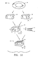
- the composite bone graft contains two or more distinct bone portions where the bone portions are connected.
- the bone portions are preferably self-locking, interlocking, and/or connected by at least one mechanical connector, including for example, a bone pin.
- One or more of the bone portions may be demineralized, and may also be continuous or discontinuous.
- the composite bone graft may include one or more textured surfaces, preferably including a plurality of closely spaced protrusions.
- the composite bone graft is useful for repairing bone defects caused by congenital anomaly, disease, or trauma, and is particularly useful for spinal fusions.
- the composite bone graft can be appropriately sized for any application and can be used to replace traditional non-bone prosthetic implants.
- the composite bone graft promotes the growth of patient bone at an implantation site by promoting osteoinductivity and cellularization, provides added stability and mechanical strength, and does not shift, extrude or rotate, after implantation.
- materials often used include bone grafts and implants produced from non-bone materials, including for example stainless steel, titanium and plastics.
- non-bone materials including for example stainless steel, titanium and plastics.
- the choice of whether to use a bone or a non-bone implant often depends on the clinical indication, implant site, whether the implant is load-bearing, and the size of the implant needed.
- the success or failure of a bone graft further depends on whether the bone graft remains at the implant site, is cellularized, and whether it can withstand the mechanical load.
- allograft bone there are two primary indications for use of allograft bone: (1) when there is insufficient available autograft bone, and (2) in spinal fusion procedures when a structural element in needed.
- bone grafts are affixed at an implant site by fusion. Bone grafts for spinal applications often fail because they are extruded from the implantation site due to shifting, rotation, and slippage of the graft, are not cellularized, or fail mechanically.
- the invention enables the use of bone grafts for applications normally suited for only non-bone prosthetic implants.
- the invention solves the problem of graft failure by providing a composite bone graft which can be appropriately sized for any application out of for example, strong cortical bone; promotes the ingrowth of patient bone at an implantation site by promoting osteoinductivity and cellularization; provides added stability and mechanical strength; and does not shift, extrude or rotate; after implantation.
- the present invention is directed to a composite bone graft for repairing bone defects caused by congenital anomaly, disease, or trauma, including for example, for restoring vertical support of the posterior and/or anterior column.
- the present composite bone grafts can be used as structural grafts placed posteriorly in the spine as interbody grafts or as strut grafts spanning multiple segments.
- Posterior composite bone grafts can be used to supplement autologous bone for spinal fusions in patients who lack sufficient host bone and to avoid significant donor site morbidity.
- the present composite bone grafts can be used for applications normally suited for only non-bone prosthetic implants because the composite bone graft can be appropriately sized for any application and has adequate mechanical strength.
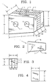
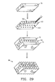
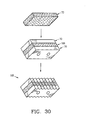
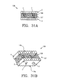
- the invention provides a composite bone graft including a plurality of bone portions layered to form a graft unit, and one or more biocompatible connectors for holding together the graft unit.
- the invention also provides a composite bone graft including two or more distinct bone portions, and one or more biocompatible connectors, where the biocompatible connectors hold together the two or more bone portions to form the composite bone graft.
- the present invention provides a composite bone graft including two or more connected, distinct bone portions.
- the present invention provides a composite bone graft including three or more connected, distinct bone portions.
- the present invention provides a composite bone graft including three or more connected, distinct cortical bone portions.
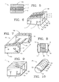
- the present invention provides a composite bone graft including one or more horizontally disposed channels provided through the composite bone graft perpendicular to the interfaces of the bone portions.
- the present invention also provides a composite bone graft including one or more vertically disposed channels provided through the composite bone graft parallel to the interfaces of the bone portions.
- the present invention further provides a composite bone graft including one or more horizontally disposed channels and vertically disposed channels where the one or more channels includes one or more therapeutically beneficial substances.
- the invention further provides a composite bone graft including two or more connected bone portions, where the bone portions can include cortical bone and cancellous bone.
- the invention also provides a composite bone graft, including a first bone portion, a second bone portion, a third bone portion, the first, second and third bone portions are disposed one on the other (ie. layered) to form a graft unit; and one or more biocompatible connectors for holding together the graft unit.
- the invention provides a composite bone graft, including a first cortical bone portion, a second cortical bone portion, a cancellous bone portion disposed between the first cortical bone portion and the second cortical bone portion to form a graft unit, and one or more biocompatible connectors for holding together the graft unit.
- the invention further provides a composite bone graft, including a first cortical bone portion, a second cortical bone portion provided on the first cortical bone portion to form a graft unit; and one or more biocompatible connectors for holding together the graft unit.
- the invention provides a composite bone graft, including a plurality of layered cortical bone portions forming a graft unit, and one or more biocompatible connectors for holding together the graft unit.
- the invention provides a composite bone graft, including a plurality of layered bone portions forming a graft unit, and one or more biocompatible connectors for holding together the graft unit.
- the invention also provides a composite bone graft, including a first bone portion, a second bone portion provided on the first bone portion to form a graft unit, and one or more biocompatible connectors for holding together the graft unit
- the invention provides a composite bone graft including a plurality of distinct bone portions, where one or more of the bone portions are demineralized.
- the invention provides a composite bone graft including a plurality of distinct bone portions, where one or more of the bone portions are continuous or discontinuous.
- the invention further provides a composite bone graft including a plurality of distinct bone portions where one or more of the bone portions include a discontinuous bone portion, the discontinuous bone portion including one or more therapeutically beneficial substances including but not limited to, for example, one or more of the following: osteoinductive substances, osteoconductive substances, and pharmaceutically active agents.
- therapeutically beneficial substances may optionally be provided with a carrier.
- Suitable osteoinductive substances include but are not limited to, for example, autograft bone; allograft bone; GraftonTM produced by Osteotech; DynaGraftTM; demineralized cortical bone; demineralized cancellous bone; collagen including one or more growth factors including for example NovusTM produced by Stryker Biotech; collagen including demineralized bone including for example DynaGraftTM; cancellous bone; cortical bone; OpteoFormTM produced by the University of Florida; OsteoFillTM produced by the University of Florida; and growth factors including for example, bone morphogenic protein, and transforming growth factor- ⁇ .
- Suitable osteoconductive substances include but are not limited to, for example, hydroxyapitate; collagen; any biocompatible matrix material including for example, polymeric matrix materials, bioglass, bioceramics, resorbable Biomaterials; bioabsorbable polymers; a plastic matrix; stainless steel; titanium; cobalt-chromium-molybdenum alloy matrix; and substances including hydroxyapitate, including for example, OsteosetTM produced by Wright Medical.
- Suitable pharmaceutically active agents include but are not limited to, for example, growth factors including for example bone growth factors including for example bone morphogenic protein, and transforming growth factor- ⁇ , chemotherapeutic agents, anti-inflammatory agents, and antibiotics.
- the invention also provides a composite bone graft, including a first cortical bone portion, a second cortical bone portion, a cancellous bone portion disposed between the first cortical bone portion and the second cortical bone portion to form a graft unit, and one or more biocompatible connectors for holding together the graft unit, where the cancellous bone portion is demineralized and discontinuous.
- the invention provides a composite bone graft, including a first cortical bone portion, a second cortical bone portion, and a third cortical bone portion disposed between the first cortical bone portion and the second cortical bone portion to form a graft unit, and one or more biocompatible connectors for holding together the graft unit, where the third cortical bone portion is demineralized and discontinuous.
- the invention provides a composite bone graft, including a first cortical bone portion, and a second cortical bone portion disposed apart from each other, and forming a graft unit, and one or more biocompatible mechanical connectors for holding together the graft unit, where the first and second cortical bone portions are disposed separate from each other by the biocompatible mechanical connectors, thereby forming a substantially void central area.
- the invention further provides a composite bone graft including a substantially void central area, where the substantially void central area further includes one or more therapeutically beneficial substances including but not limited to, for example, one or more of the following: osteoinductive substances, osteoconductive substances, and pharmaceutically active agents.
- therapeutically beneficial substances may optionally be provided with a carrier.
- Suitable osteoinductive substances include but are not limited to, for example, autograft bone; allograft bone; GraftonTM produced by Osteotech; DynaGraftTM; demineralized cortical bone; demineralized cancellous bone; collagen including one or more growth factors including for example NovusTM produced by Stryker Biotech; collagen including demineralized bone including for example DynaGraftTM ; cancellous bone; cortical bone; OpteoFormTM produced by the University of Florida; OsteoFillTM produced by the University of Florida; and growth factors including for example bone morphogenic protein, and transforming growth factor- ⁇ .
- Suitable osteoconductive substances include but are not limited to, for example, hydroxyapitate; collagen; any biocompatible matrix material including for example, polymeric matrix materials, bioglass, bioceramics, resorbable Biomaterials; bioabsorbable polymers; a plastic matrix; stainless steel; titanium; cobalt-chromium-molybdenum alloy matrix; and substances including hydroxyapitate, including for example, OsteosetTM produced by Wright Medical.
- Suitable pharmaceutically active agents include but are not limited to, for example, growth factors including for example bone growth factors including for example bone morphogenic protein, and transforming growth factor- ⁇ ; chemotherapeutic agents; anti-inflammatory agents; and antibiotics.
- the material may be in any suitable form including for example, in the form of a solid, sponge, paste, powder, and/or gel.
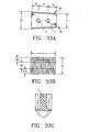
- the invention further provides a composite bone graft where the biocompatible connectors include one or more mechanical biocompatible connectors.
- the invention provides a composite bone graft where the biocompatible connectors include a chemical biocompatible connector.
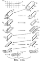
- the invention further provides a composite bone graft where the mechanical biocompatible connectors include one or more pins.
- the invention further provides a composite bone graft where the chemical biocompatible connectors include a biocompatible adhesive.
- the invention provides a composite bone graft where one or more biocompatible connectors include one or more of the following: a mechanical connector and a chemical connector.
- the invention also provides a composite bone graft where the mechanical biocompatible connectors include one or more of the following biocompatible materials: cortical bone; stainless steel; titanium; cobalt-chromium-molybdenum alloy; a bioceramic; a bioglass; a plastic of one or more of the following: nylon, polycarbonate, polypropylene, polyacetal, polyethylene, and polysulfone; and one or more bioabsorbable polymers.
- the invention also provides a composite bone graft where the mechanical biocompatible connectors include cortical bone.
- the invention provides a composite bone graft where the one or more pins include one or more cortical bone pins.
- the invention provides a composite bone graft where the graft unit includes one or more through-holes configured to accomadate the one or more pins.
- the invention further provides a composite bone graft where the through-holes are disposed perpendicular to interfaces of bone portions forming the graft unit.
- the invention further provides a composite bone graft where the through-holes are disposed perpendicular to interfaces of for example, the first bone portion, the second bone portion, and the third bone portion, of the graft unit.
- the invention provides a composite bone graft where the one or more pins and the one or more through-holes are configured to provide an interference fit tor holding together the graft unit.
- the invention also provides a composite bone graft where the one or more through-holes and the one or more pins are round and an inner diameter of a through-hole is smaller than a diameter of a pin, to provide an interference fit between the through-hole and the pin.
- the invention further provides a composite bone graft where the one or more cortical bone pins include a plurality of vertical groves provided on a surface thereof.
- the invention further provides a composite bone graft where the one or more cortical bone pins includes a roughened surface.
- the invention provides a composite bone graft where the one or more cortical bone pins further includes a slot extending from one end of the bone pin.
- the invention provides a composite bone graft where the one or more pins is threaded to provide a threaded engagement with the one or more through-holes.
- the invention further provides a composite bone graft where the one or more pins is threaded and the one or more through-holes is threaded, to provide a threaded engagement between the one or more pins and the one or more through-holes.
- the invention provides a composite bone graft where the one or more pins and the one or more through-holes are configured to provide a slidable connection, for example, to provide a composite bone graft including a substantially void central area.
- the invention also provides a composite bone graft where a cross-section of the one or more pins includes a shape selected from the group including the following: round, ovoid, square, rectangular, triangular, pentagon, hexagon, and trapezoidal.
- the invention further provides a composite bone graft including a plurality of plate-like cortical bone portions, the cortical bone portions layered to form a graft unit, the graft unit held together with one or more cortical bone pins.
- the invention further provides a composite bone graft where the composite bone graft is a cortical cylinder.
- the invention provides a composite bone graft including a graft unit having one or more through-holes configured to accomadate one or more pins, the graft unit including two or more bone portions layered to form the graft unit, and one or more pins for holding together the graft unit.
- the invention further provides a composite bone graft, including a graft unit having one or more through-holes configured to accomadate one or more pins, the graft unit including a first plate-like cortical bone, a second plate-like cortical bone, a plate-like cancellous bone disposed between the first plate-like cortical bone and the second plate-like cortical bone to form the graft unit, and one or more cortical bone pins for holding together the graft unit.
- the invention also provides a composite bone graft, including a graft unit having one or more through-holes configured to accomadate one or more pins, the graft unit including a first plate-like bone, a second plate-like bone provided on the first plate-like bone to form the graft unit, and one or more bone pins for holding together the graft unit.
- the invention also provides a cervical composite bone graft, including a flattened curved wedge graft unit having one or more through-holes configured to accomadate one or more pins, the graft unit including two or more plate-like cortical bone portions layered to form the graft unit, and at least two bone pins for holding together the graft unit, where the graft unit includes a substantially centrally located through-hole.
- the diameter of the through-hole may be readily selected by one of ordinary skill in the art without undue experimentation depending upon the particular application; for example, the diameter of the through-hole may be from about 2.0 mm-4.0 mm; preferably 2.5 mm-3.0 mm; and more preferably 3.0 mm.
- the invention also provides a composite bone graft where the one or more through-holes are disposed perpendicular to interfaces of plate-like bones of the graft unit.
- the invention provides a composite bone graft where the composite bone graft is a parallelepiped; a parallel block; a square block; a trapezoid wedge; a cylinder; a tapered cylinder; a cervical wedge (flattened curved wedge); an ovoid wedge (anterior lumbar wedge graft) and a polyhedron.
- the invention further provides a composite bone graft where the composite bone graft is a polyhedron including six planer surfaces.
- the invention provides a composite bone graft where the composite bone graft further includes one or more textured surfaces.
- the invention also provides a composite bone graft where the one or more textured surfaces includes a plurality of closely spaced continuous protrusions.
- the invention provides a composite bone graft where the continuous protrusions include a cross-section having one or more shapes selected from the following: irregular; triangular, square, rectangular, and curved.
- the invention further provides a composite bone graft where the plurality of continuous protrusions are sized to be in a range of greater than or equal to about 1.5 mm in length; 0.5 to about 10.0 mm in width and 0.1 to about 5.0 mm in depth.
- the invention provides a composite bone graft where the plurality of closely spaced continuous protrusions are spaced from about 0.0 to about 3.0 mm apart.
- the invention provides a composite bone graft where the plurality of protrusions are spaced from about 0.1 to about 2.0 mm apart.
- the invention also provides a composite bone graft where the plurality of protrusions are spaced about 0.5 mm apart.
- the invention provides a method for restoring vertical support of the posterior and/or anterior column by implanting a composite bone graft including two or more distinct bone portions held together by one or more connectors, at a site in a patient.
- the invention provides a composite bone graft containing two or more connected bone portions, where the composite bone graft has a plurality of closely spaced protrusions on one or more surfaces thereof, where the protrusions are continuous protrusions, discrete protrusions, or a combination thereof.
- the invention provides a composite bone graft where the plate-like cortical and/or cancellous bone portions are continuous bone portions and/or discontinuous bone portions.
- the invention provides a composite bone graft including one or more discontinuous bone portions.
- the invention provides a composite bone graft including one or more discontinuous, demineralized cortical bone portions.
- the invention provides a composite bone graft including one or more discontinuous, demineralized cancellous bone portions.
- the invention further provides a composite bone graft where one or more continuous or discontinuous cancellous bone portions, (continuous or discontinuous and/or demineralized)includes one or more therapeutically beneficial substances including but not limited to, for example, one or more of the following: osteoinductive substances, osteoconductive substances, and pharmaceutically active agents.
- therapeutically beneficial substances may optionally be provided with a carrier.
- Suitable osteoinductive substances include but are not limited to, for example, autograft bone; allograft bone; GraftonTM produced by Osteotech; DynaGraftTM; demineralized cortical bone; demineralized cancellous bone; collagen including one or more growth factors including for example NovusTM produced by Stryker Biotech; collagen including demineralized bone including for example DynaGraftTM; cancellous bone; cortical bone; OpteoFormTM produced by the University of Florida; OsteoFillTM produced by the University of Florida; and growth factors including for example bone morphogenic protein, and transforming growth factor- ⁇ .
- Suitable osteoconductive substances include but are not limited to, for example, hydroxyapitate; collagen; any biocompatible matrix material including for example, polymeric matrix materials, bioglass, bioceramics, resorbable Biomaterials; bioabsorbable polymers; a plastic matrix; stainless steel; titanium; cobalt-chromium-molybdenum alloy matrix; and substances including hydroxyapitate, including for example, OsteosetTM produced by Wright Medical.
- Suitable pharmaceutically active agents include but are not limited to, for example, growth factors including for example bone growth factors including for example bone morphogenic protein, and transforming growth factor- ⁇ ; chemotherapeutic agents; anti-inflammatory agents; and antibiotics.
- the invention provides a composite bone graft where one or more continuous or discontinuous cancellous bone portions are demineralized and include one or more therapeutically beneficial substances.
- the invention provides a composite bone graft where one or more discontinuous cortical bone portions, include one or more therapeutically beneficial substances.
- the invention further provides a composite bone graft where one or more discontinuous cortical bone portions are demineralized and include one or more therapeutically beneficial substances.
- the invention also provides a composite bone graft including a two or more distinct bone portions held together by one or more connectors, where the composite bone graft includes two diametrically opposing chamfered edges, one provided along the length of the graft at its top edge and the other provided along the length of the graft at its bottom edge, such that the chamfered edges are diametrically opposing.
- the invention further provides a composite bone graft including two or more distinct interlocking cortical bone portions.
- the invention provides a composite bone graft including two or more distinct interlocking bone portions, where the interlocking bone portions are self-locking.
- the invention also provides a composite bone graft including two or more distinct interlocking bone portions, where the interlocking bone portions are locked with one or more locking pins.
- the invention further provides a composite bone graft where bone portions are locked with one or more locking pins entirely or partially traversing a dimension of the composite bone graft.
- the invention provides an interlocking composite bone graft where each complementary bone portion is provided with a discrete or continuous interlocking pattern.
- the invention also provides an interlocking composite bone graft including two or more distinct adjacent bone portions where adjacent bone portions are configured to interlock with each other, and one or more bone pins partially or entirely traversing a dimension of the graft, where the dimension of the graft is the length, width, or height of the graft.
- the invention provides an interlocking composite bone graft including two or more distinct adjacent bone portions where adjacent bone portions are configured to interlock with each other.
- the invention provides a composite bone graft including two or more distinct adjacent interlocking bone portions where adj acent bone portions include complementary peg-like protrusions and corresponding depressions, such that the protrusions and depressions provide an interlocking fit between the bone portions.
- Bioabsorbable polymers are intended for the purposes of the present invention, bioresorbable, bioabsorbable, biodegradable, and bioerodible materials that are well known to those of ordinary skill in the art and are described in Biomaterials Science-An Introduction to Materials in Medicine, edited by Ratner, B. D.
- chitosan include for example, the following materials: chitosan; isomorphic ploy(hexamethylene co-trans-1,4-cyclohexane dimethylene oxalates); poly(glycolic acid); copolymers of poly(glycolic acid) and poly(lactic acid); polydioxanone; poly(latic acid); polymers having a back-bone structure selected from the group consisting of: polyanhydrides, polyphophazenes, polyphosphonates, polyamides, and polyiminocarbonates; polyhydroxybutyrate; polyhydroxyvalerate; copolymers of polyhydroxybutyrate and polyhydroxyvalerate; polycaprolactone; polydioxanone; poly( ⁇ -ethyl glutamate); poly (DTH iminocarbonate); poly(Bisphenol A iminocarbonate); poly(DETOSU-1,6 HD-t-CDM ortho ester); poly(Sebacic acid-hexade
- Such polymers may optionally include one or more pharmaceutically active agents for controlled release applications, such agents including for example: osteoinductive factors including for example bone morphogenic protein; growth factors including for example transforming growth factor- ⁇ ; chemotherapeutic agents; antiobiotics; and anti-inflammatory agents.
- agents including for example: osteoinductive factors including for example bone morphogenic protein; growth factors including for example transforming growth factor- ⁇ ; chemotherapeutic agents; antiobiotics; and anti-inflammatory agents.
- Biocompatible By the term “biocompatible” is intended for the purposes of the present invention, any material which when implanted in a patient does not provoke an adverse response in the patient. A suitable biocompatible material when introduced into a patient is not toxic or injurious to that patient, or does not cause immunological rejection.
- Biomechanical strength is intended for the purposes of the present invention, those properties exhibited by a bone graft, including loading strength, compressive strength, and tensile strength.
- Bone is intended for the purposes of the present invention, bone recovered from any source including animal and human, for example, human bone recovered for the production of allografts, and animal bone recovered for the production of xenografts, such allografts and xenografts suitable for implantation into a human.
- Such bone includes: any bone or portion thereof, including cut pieces of bone, including cortical and/or cancellous bone, for example, recovered from a human including a living human or a cadaver, or animal, and processed for implantation into a living patient.
- Such bones including for example: the humorous, hemi-pelvi, tibia, fibula, radius, ulna, rib, vertebrae, mandibular, femur, and ilia, and any cut portion thereof.
- Such bone may be demineralized or not demineralized.
- a cancellous or cortical bone section is demineralized and disposed between two non-demineralized cortical bone portions.
- Suitable bone may also include continuous or discontinuous bone portions.
- one or more bone portions of a composite bone graft may be discontinuous, for example, a bone portion may be perforated and demineralized, for example perforated either before or after demineralization, for example, to allow for uniform demineralization (perforations before demineralization) and to promote ingrowth of patient bone.
- Cancellous and/or demineralized cancellous and/or discontinuous cancellous and/or demineralized discontinuous cancellous and or discontinuous cortical and/or demineralized discontinuous cortical, bone may optionally include one or more therapeutically beneficial substances provided with or without a carrier.
- the composite bone graft may include a substantially void central area, where the substantially void central area further includes one or more therapeutically beneficial substances provided with or without a carrier.
- the material may be in any suitable form including for example, in the form of a solid, sponge, paste and/or gel.
- Bone marrow elements By the term “bone marrow elements" is intended for the purposes of the present invention, the highly cellular hematopoietic connective tissue filling the medullary cavities and spongy epiphysis of bones which may harbor bacterial and/or viral particles and/or fungal particles, and includes for example, blood and lipid.
- Chamfer By the term “chamfer” is intended for the purposes of the invention, an oblique face formed at a corner of a composite bone graft, at an angle to the adjacent principal faces. Suitable angles include angles in the range of from 38° to 52°, more preferably 40° to 50°, even more preferably 42 ° to 48 °, and most preferably about 45 °.
- Cleaned bone is intended for the purposes of the present invention, a bone or cut portion thereof, that has been processed using means known in the art, to remove bone marrow elements.
- protrusions discrete or continuous which are in close proximity to each other.
- the protrusions are spaced no more than 3.0mm apart (i.e. the distance between the edges of two adjacent protrusions), more preferably no more than 2.0mm apart, even more preferably no more than 1.5mm apart, and most preferably about 0.5mm apart
- composite By the term “composite” is intended for the purposes of the present invention, a bone graft which is made up of two or more distinct bone portions.
- Connector By the term “connector” is intended for the purposes of the present invention, a means of connecting two or more distinct bone portions, including for example a chemical and/or mechanical means.
- mechanical connector By the term “mechanical connector” is intended for the purposes of the present invention, a structural member including for example, a pin.
- chemical connector By the term “chemical connector” is intended for the purposes of the present invention, a biocompatible composition including for example, one or more biocompatible adhesives and one or more surface modification agents and methods.
- Continuous Bone Portion is intended for the purposes of the present invention, a bone portion that is substantially solid without any artificial void areas.
- Continuous protrusion is intended for the purposes of the present invention, a protrusion whose length continues substantially uninterrupted, including for example a linear or curved protrusion whose length is at least three times greater than its width, preferably at least five times greater, and includes for example a continuous, protruding concentric ring, and a continuous linear protrusion, for example, as illustrated in Fig 2 .
- Each continuous protrusion may or may not be distinct from another continuous protrusion.
- Demineralized Bone By the term “demineralized bone” is intended for the purposes of this invention, one or more distinct bone portions which have been demineralized by any method well known to those of ordinary skill in the art.
- Cortical bone is preferably demineralized in .5 to .6 N hydrochloric acid for a period of time of from about 1 to about 8 hours, more preferably for a time period of about two hours, at 25 °C to 50°C, more preferably at 25 °C to 37°C.
- Cancellous bone is preferably demineralized in .5 to .6N hydrochloric acid for a period of time of from about 20 minutes to about 6.0 hours, more preferably for a time period of from about 30minutes to about 2.0 hours.
- cortical and/or cancellous bone is demineralized to contain less than 10 wt% residual calcium, more preferably about less than 5 wt% residual calcium, even more preferably about I wt% to about 3 wt%, and most preferably about 2 wt% residual calcium.
- Other methods for demineralizing bone are well known in the art to which the present invention pertains, and can be readily selected and employed by one of ordinary skill in the art, without undue experimentation.
- discontinuous bone portion a bone portion that contains artificially created void areas including for example, a perforated bone portion, where the perforations or channels may be of any shape and may partially or completely transverse the bone portion. Such perforations may be randomly disposed or disposed in a regular pattern on and/or through the bone portion. Suitable perforations include perforations traversing the width of the bone portion provided perpendicular to the interfaces of the bone portions of the composite graft, and channels traversing the height of the bone portion provided parallel to the interfaces of the bone portions of the composite graft. Such perforations allow for uniform demineralization of a bone portion, and allow for ingrowth of patient bone. A demineralized discontinuous bone portion may be perforated prior to demineralization or after demineralization.
- Discrete Protrusion is intended for the purposes of the present invention, a protrusion which is discontinuous, i.e. which has a distinct length and width, where each discrete protrusion is separate and distinct from every other discrete protrusion, and includes for example a protrusion whose length is less than three times its width, preferably less than twice its width and more preferably a protrusion whose length is about equal to its width.
- Interlocking is intended for the purposes of the present invention, any pattern provided on a bone portion which allows that bone portion to engage or interlace with another bone portion, such that the engaged bone portions act as a single bone portion when stressed.
- Such bone portions may be provided with engaging patterns including but not limited to the following: step patterns, sawtooth patterns, and ridged patterns, patterns that define mortise and tenon joints, and lock and key type patterns. These patterns may be either discrete, for example one bone portion may include one or more protrusions and a complementary bone portion may be provided with one or more corresponding depressions, or continuous, for example bone portions are provided with complementary continuous grooves (See figs. 39, 40, and 41 ).
- the discrete patterns may include protrusions and corresponding depressions of any shape and size sufficient to provide an interlocking fit, and include round, square, rectangular, triangular, oval, irregular, and any combination of geometric and curved shaped protrusions and corresponding depressions.
- the depth/height of the discrete or continuous patterns is from about 0.1mm to about 3.5mm, preferably from about 0.2mm to about 2.0mm, more preferably from about 0.3mm to 1.5mm, and most preferably from about 0.5mm to about 1.0mm.
- Adjacent bone portions provided with interlocking patterns may be self-locking such that no other connecting means, for example one or more pins, is necessary to form a unitary structure, ie. to hold the composite bone graft together.
- interlocking bone portions may be "locked" to form a unitary structure using other connection means, for example, one or more pins partially or entirely traversing a dimension of the composite bone graft, where the dimension is for example the height, width, or length of the composite bone graft.
- Load-bearing is intended for the purposes of the present invention a non-demineralized bone product for implantation in a patient at a site where the bone graft will be expected to withstand some level of physical load(s).
- Locking pin By the term “locking-pin” is intended for the purposes of the present invention, one or more pins entirely or partially traversing a dimension of a composite bone graft which serve to hold the bone graft together, for example, two or more interlocking bone portions provided with complementary patterns for example, a stepped pattern, may be locked using one or more pins, for example, one bone pin partially traversing the length of the graft.
- Mechanical strength is intended for the purposes of the present invention, the ability of a bone allograft to withstand mechanical loads at an implant site without failing.
- Materials properties are intended for the purposes of the present invention, those properties present in normal fresh bone and include loading strength, compressive strength, tensile strength, and brittleness.
- normal bone By the term “normal bone” is intended for the purposes of the present invention, fresh hydrated autogenous and/or fresh-frozen hydrated allograft bone tissue.
- Osteoconductivity is intended for the purposes of the present invention, the ability of a substance which by its presence conducts osteoinductive activity.
- Suitable osteoconductive materials include but are not limited to, for example, one or more biocompatible matrix materials.
- Suitable osteoconductive substances include but are not limited to, for example, hydroxyapitate; collagen; any biocompatible matrix material including for example, polymeric matrix materials, bioglass, bioceramics, resorbable Biomaterials, bioabsorbable polymers, a plastic matrix, stainless steel, titanium, and cobalt-chromium-molybdenum alloy matrix; and substances including hydroxyapitate, including for example, OsteosetTM produced by Wright Medical.
- Osteoinductivity is intended for the purposes of the present invention, the ability of a substance to promote bone growth.
- suitable osteoinductive substances include but are not limited to, for example, autograft bone; allograft bone; GraftonTM produced by Osteotech; DynaGraftTM; demineralized cortical bone; demineralized cancellous bone; collagen including one or more growth factors including for example NovusTM produced by Stryker Biotech; collagen including demineralized bone including for example DynaGraftTM; cancellous bone; cortical bone; OpteoFormTM produced by the University of Florida; OsteoFill TM produced by the University of Florida; growth factors including for example, bone morphogenic protein and transforming growth factor- ⁇ .
- the bone is demineralized to contain less than 6 wt% residual calcium, more preferably demineralized to contain 1 wt% to about 3 wt% residual calcium, and most preferably demineralized to contain about 2 wt% residual calcium.
- Parallelepiped By the term “parallelepiped” is intended for the purposes of the present invention, a six-faced polyhedron all of whose faces are parallelograms lying in pairs of parallel planes.
- Polyhedron By the term “polyhedron” is intended for the purposes of the present invention, a solid formed by plane faces, preferably formed by six faces.
- Protrusion is intended for the purposes of the present invention, an irregularity in a surface of a bone allograft having a height of from 0.1 to 5.00 mm, preferably 0.3 to 3.0 mm, more preferably 0.5 to 1.5 mm, and most preferably .75mm to 1.2mm.
- the protrusions can be discrete, continuous, or a combination thereof, and can be of any shape including for example: irregular; pyrimidal; conical; cuboidal; rectangular; and cylindrical; or any combination thereof.
- a cross-section of a continuous or discrete protrusion may be of any shape including for example: irregular; rectangular; square; oval; round; triangular; trapizoidal; and a regular or irregular curve; or any combination thereof.
- the protrusions can be provided on the bone allograft surface in a regular, symmetric pattern including for example a linear pattern or in an irregular pattern.
- Self-locking, interlocking pattern is intended for the purposes of the present invention, any complementary patterns provided on adjacent bone portions which enable the bone portions: to interlock, act as a unitary structure, and the bone portions are held together, without the use of any additional connecting means.
- Stability is intended for the purposes of the present invention the ability of the present composite bone graft to remain at an implantation site without significantly shifting, rotating, or being extruded.
- Stress is intended for the purposes of the present invention, load per unit cross-sectional area.
- a composite bone graft having one or more textured surfaces provided on the surface of the composite bone graft where the surface of the composite bone graft can be any surface or a portion of any surface including a natural surface and/or a cut surface.
- the textured surface preferably includes a plurality of protrusions provided on the surface or a portion thereof, the protrusions of a shape including for example, irregular; pyrimidal; conical; cuboidal; rectangular; trapizoidal; curved; and cylindrical; or any combination thereof.
- the protrusions can be discrete, continuous, or a combination thereof.
- Therapeutically beneficial is intended any material which by its action or presence, bring about a therapeutic result in a patient.
- Such materials include but are not limited to, for example, one or more of the following: osteoinductive substances, osteoconductive substances, and pharmaceutically active agents.
- Such therapeutically beneficial substances may optionally be provided with a carrier.
- Suitable osteoinductive substances include but are not limited to, for example, autograft bone; allograft bone; GraftonTM produced by Osteotech; DynaGraftTM; demineralized cortical bone; demineralized cancellous bone; collagen including one or more growth factors including for example NovusTM produced by Stryker Biotech; collagen including demineralized bone including for example DynaGraftTM; cancellous bone; cortical bone; OpteoFormTM produced by the University of Florida; OsteoFillTM produced by the University of Florida; growth factors including for example bone morphogenic protein, and transforming growth factor- ⁇ .
- Suitable osteoconductive substances include but are not limited to, for example, hydroxyapitate; collagen; any biocompatible matrix material including for example, polymeric matrix materials, bioglass, bioceramics, resorbable Biomaterials; bioabsorbable polymers; a plastic matrix; stainless steel; titanium; cobalt-chromium-molybdenum alloy matrix; and substances including hydroxyapitate, including for example, OsteosetTM produced by Wright Medical.
- Suitable pharmaceutically active agents include but are not limited to, for example, growth factors including for example bone growth factors including for example bone morphogenic protein, and transforming growth factor- ⁇ , and transforming growth factor- ⁇ ; chemotherapeutic agents; anti-inflammatory agents; and antibiotics.
- Suitable bone tissue includes bone obtained from any animal or human source.
- bone graft tissue can be obtained from the patient himself (autologous bone) or from a cadaver (allograft bone).
- allograft bone tissue is used, it is processed under strict aseptic conditions in certified clean room operating suites.
- the bone tissue is preferably processed to remove all soft tissue, including marrow and blood, to produce a cleaned bone graft.
- Suitable processing methods are well known to those skilled in the art and can be readily selected and employed by those of ordinary skill in the art without undue experimentation. Suitable methods include the methods disclosed in, for example, United States Patent Nos: 5,556,379 ; 5,820,581 ; and 5,797,891 .
- the cleaned grafts are packaged under sterile conditions and stored for latter processing into the present composite bone allograft, or immediately processed into the present composite bone allograft followed by appropriate packaging.
- the use of fresh-frozen and/or freeze-dried, bone allografts are preferred.
- FIG 11A illustrates a preferred method 60 of making the present composite bone graft.
- a composite bone graft having of any size necessary for a particular application, can be made using the preferred method discussed hereafter.
- a cortical bone shaft 61 is obtained from a cadaver and is transected into cortical sections 62 having a length 63 of at least 18.0 mm, preferably at least 21.0 mm.
- a cortical section 62 is then first cut to produce a cortical plank 64, the remaining cortical section 62a is turned and again cut to produce a second cortical plank, the remaining cortical plank 62b is again turned and cut into third and fourth cortical planks 64 .
- the cortical planks 64 are cut to an appropriate width 65 and thickness 66 .
- the concave surface 64a of the plank 64 can be smoothed if needed to produce a smoothed plank 67 .
- Opposing edges 67a and 67b can be cut such that the cut surfaces 67c and 67d are approximately parallel.
- the cut width 68 should be larger than the final composite bone graft width. More specifically, cut width 68 is preferably greater than about 12.0mm.
- the convex surface 64b of plank 64 is then smoothed to produce a smoothed plank 69 .
- the smoothed plank 64 is further smoothed by for example, milling, such that the opposing surfaces 64a and 64b, and 67c and 67d , are parallel, to produce a parallel plank 70 having a thickness 71 of at least 1.0 mm, preferably from about 1.5 mm to about 6.0 mm, and more preferably from about 2.0 mm to about 5.5 mm.
- FIG 11B illustrates cortical pins 7 cut from a cortical section 62 , using for example a drill press 72 or other means known in the art.
- the cortical pins 7, can also be made from a cortical plank 64 , for example by turning on a lathe.
- the pins 7 have a diameter of from about 1.0 to about 6.0 mm, preferably from about 1.5 mm to about 4.5 mm, and more preferably from about 2.0 mm to about 4.0 mm.
- cancellous bone planks 73 are produced and sized by the method as described above for producing cortical bone planks 6 9 and 70.
- the composite bone unit 74 is then assembled as desired, for example a cortical parallel plank 70 , a cancellous plank 73 , and another cortical parallel plank 70 .
- the composite bone unit 74 has a height 74a , a width 74b and a length 74c .
- the height 74a, width 74b and length 74c can be readily selected by one of ordinary skill in the art, depending on factors including for example, the particular application and site of implantation in a patient.
- the planks are secured and holes 5 are drilled there through.
- the through-holes 5 are sized such that a tight or frictional fit is provided between a pin 7 and a though-hole 5 .
- the cortical pins 7 are then inserted through the through-holes 5 , and pressed to fit if needed, to produce pinned composite graft 75 .
- the cortical bone pins 7 have a diameter 8 sufficient to provide an interference fit or frictional fit between a pin 7 and a through-hole 5 . More specifically the diameter 8 of a cortical pin 7 is generally the same or slightly larger than the diameter 6 of a through-hole 5 into which it is to be inserted.
- the diameter of the pin 7 is preferably no more than 1.5mm larger than the diameter of the through-hole 5 .
- the assembled pinned graft can thereafter be shaped as desired, for example into a trapezoid shaped graft and appropriately dimensioned to produce a composite bone graft.
- One or more surfaces of the composite bone graft may be textured if desired, for example, depending upon the particular application.
- Figure 12 illustrates an additional method 33 of making a preferred embodiment of the present composite bone graft.
- a cross-section of a femur is obtained from a cadaver, and cleaned using methods well known to those of ordinary skill in the art to which the present invention pertains, to remove bone marrow elements thereby producing the cleaned femural ring 34 .
- the cleaned femural ring is then sectioned into several sections of cortical bone including a first cortical bone portion 35 and a second cortical bone portion 36 , each portion having a width 37 of from about 2.0 to about 10.0 mm; preferably of from about 4.0 to about 8.0 mm; and more preferably of from about 5.0 to about 6.0 mm.
- Portions 35 and 36 are then held together to form a graft unit 38 having a width of 39 which is at least 4.0 mm; preferably greater than 9.0 mm; using for example, a clamp, and one or more through-holes 5 having a diameter 6 of about 0.5mm to about 10.0 mm, preferably 2.0mm to about 5.0 mm, more preferably 2.0mm to about 4.0 mm, are then drilled there through.
- Cortical pins 7 are produced from cortical bone by methods well known to those of ordinary skill in the art to which the present invention pertains.
- the pins 7 have a diameter of from 1.0mm to about 6.0 mm, preferably from about 1.5mm to about 4.5mm, and more preferably from about 2.0mm to about 4.0mm.
- the graft unit 38 having through-holes 5 drilled there through is then placed in a press and one or more cortical pins 7 are inserted into the through-holes 5 .
- one or more surfaces 44 of the composite bone graft 45 can be textured by for example, milling to create a desired texture including the illustrated continuous linear protrusions (sawtooth pattern).
- the composite bone graft includes opposing textured surfaces disposed perpendicular to the interface(s) of the bone portions.
- Figure 15 illustrates a preferred method for making a cervical wedge(flattened curved wedge) composite bone graft.
- Cortical planks 70 are produced and pinned using cortical pins 7 as previously described in Figures 11A and 11B to form a pinned cortical graft unit 89 .
- the pinned graft unit 89 has a height 90 , a length 91 and a width 92 .
- the pinned graft unit 89 is then cut and shaped 94 to a designated pattern 93 to form a flattened curved block 95.
- a through-hole 83 is then provided centrally through the flattened curved block 95 using for example a drill press 72 .
- top 96 and bottom 97 faces of the block 95 are then provided with a slope at an angle 98 for example by milling.
- the top 96 and/or bottom 97 faces may optionally be textured, for example by providing the faces with a plurality of pyrimidal protrusions.
- Figure 29 illustrates a method of making a composite bone graft 99 including a discontinuous, demineralized, cortical bone portion 100 disposed between two cortical bone portions 70 .
- the cortical parallel planks 70 are produced as discussed above in reference to Figure 11 .
- the discontinuous, demineralized, cortical bone portion 100 is produced by first producing a cortical parallel plank 70 , as described above in reference to Figure 11 .
- the cortical parallel plank 70 is then perforated, for example using a drill press, to create perforations 101 traversing the width of the plank, and to create channels 102 traversing the height of the plank, to produce a discontinuous bone plank 103 .
- the discontinuous bone plank 103 is then demineralized by any method well known to those of ordinary skill in the art, including for example, demineralizing in .5-.6N hydrochloric acid at from 25°C to 50°C, preferably at from 25°C to 37°C, for a period of time of from about 1 hour to about 8 hours, preferably for about 2 hours, more preferably demineralization is carried out until the discontinuous bone plank 103 contains less than 6 wt% residual calcium, preferably about 1wt% to about 3wt% residual calcium, and most preferably demineralized to contain about 2 wt% residual calcium, to produce a demineralized discontinuous plank 100 .
- the demineralized discontinuous bone plank 100 and the cortical parallel planks 70 are then assembled, shaped, and textured to produce the composite bone graft 99 , according to the methods described in reference to Figure 11 .
- Figure 30 illustrates a method of making a composite bone graft 105 including a demineralized cancellous bone portion 106 disposed between two cortical bone portions 70 .
- the cortical parallel planks 70 are produced as discussed above in reference to Figure 11 .
- the demineralized cancellous bone portion 106 is produced by first producing a cancellous parallel plank 73 , as described above in reference to Figure 11 .
- the cancellous parallel plank 73 is then demineralized by any method well known to those of ordinary skill in the art, including for example, demineralizing in .5-.6N hydrochloric acid at from 25 °C to 50°C, preferably at from 25 °C to 37°C, for a period of time of from about 20 minutes to about 6.0 hours, preferably for about 30 minutes to about 2.0 hour to produce a demineralized cancellous bone plank 106 . More preferably, demineralization is carried out until the bone plank 106 produced, contains less than 6 wt% residual calcium, preferably about 1 wt% to about 3wt% residual calcium, and most preferably demineralized to contain about 2 wt% residual calcium.
- the demineralized cancellous bone plank 106 and the cortical parallel planks 70 are then assembled, shaped, and textured to produce the composite bone graft 105 , according to the methods described in reference to figure 11 .
- Composite bone grafts including two or more distinct cortical bone portions each bone portion provided with a pattern thereon to enable the bone portions to interlock or engage, are made by first making cortical bone planks as described. After the planks are made they are each provided with a pattern, for example a discrete or continuous pattern. The patterned planks are then fitted together. The patterned planks may be self-locking, ie. provided with a "key" type pattern, to form a unitary structure, or may be locked using one or more pins entirely or partially traversing a dimension, ie. the graft's height, width, and/or length. Thereafter, the locked graft is shaped to form the composite bone graft. Suitable patterns include any complementary patterns which when provided on two or more adjacent bone portions, enable two or more bone portions to act as one, where the patterns are self-locking or are locked with one or more additional connection means, including for example one or more pins.
- the present composite bone graft provides a bone graft which can be appropriately sized for any application, has increased stability of the graft at an implant site and promotes the ingrowth of patient bone, while providing excellent mechanical strength.
- the present composite bone graft can include two or more bone portions, including any combination of cancellous and cortical bone portions, or cancellous or cortical bone portions alone, where the bone portions may optionally be demineralized, and may optionally be discontinuous, where the bone portions are connected, for example by interlocking the bone portions, and/or by one or more mechanical and/or chemical connectors.
- Any cancellous bone portion and/or discontinuous bone portion (cortical and/or cancellous), and/or any demineralized bone portion (cortical and/or cancellous) may optionally include one or more pharmaceutically active agents or therapeutically beneficial substances provided therein, for example provided in the matrix of cancellous bone, or provided in any artificially created void areas.
- Both the cortical and cancellous bone portions may be solid and continuous or may be discontinuous (i.e. include one or more "holes” or “perforations” of any shape disposed at regular or random intervals throughout the bone portion.
- Bone portions may be provided with a pattern to enable an interlocking fit between cortical bone portions.
- Suitable mechanical connectors include pin-type structures having any cross-section shape, such shapes including for example, round, square, triangular, rectangular, hexagon, pentagon, oval, and irregular.
- the pin-type structure can include surface modification, for example the surface can be roughened, or provided with a plurality of horizontally or vertically disposed grooves (horizontal or vertically relative to the length of the pin); horizontally or vertically disposed ridges; or helical threads.
- the pin or surface-modified pin can also include one or more slots extending partially or entirely through the diameter of the pin, and extending partially or entirely through the length of the pin, suitable slots include for example, a slot extending partially through the diameter of the pin, for example about half way through the diameter of the pin, and through the entire length of the pin; and a slot extending entirely through the diameter of the pin, and extending through a partial length of the pin for example, extending at least half-way through the length of the pin, preferably extending no more than about seven-eighths the length of the pin.
- suitable mechanical connectors also include cotter pins.
- a composite graft can be pinned with one or more biocompatible pins, where the pins have substantially the same diameter or have a diameter different from each other.
- Suitable diameters can be readily selected and employed by one of ordinary skill in the art to which the present invention pertains without undue experimentation depending upon, for example, the particular application and implantation site, and the size and shape of the composite graft.
- the composite graft can be pinned with one or more biocompatible pins, entirely or partially traversing a dimension of the graft, for example, the height, length, and/or width of the composite graft.
- One of ordinary skill in the art to which the present invention pertains can readily select an appropriate pin, number of pins, and determine the orientation of the pin or pins, based on for example, the particular graft, whether the graft is interlocking or not, the orientation of the graft in the body, and the clinical indication, without undue experimentation.
- Suitable chemical connectors include any biocompatible adhesive. Such adhesives are well known to those of ordinary skill in the art to which the present invention pertains, and can be readily selected and employed by those of ordinary skill in the art, without undue experimentation. Suitable chemical connectors also include known methods of biochemical surface modification. Such methods are well known to those of ordinary skill in the art to which the present invention pertains, and can be readily selected and employed by those of ordinary skill in the art, without undue experimentation.
- the chemical and/or mechanical connectors may be used alone or in any combination and may include one or more therapeutically beneficial substances including for example, one or more osteoinductive substances, one or more osteoconductive substances and one or more pharmaceutically active agents.
- the through-hole(s) of the composite bone graft may also include surface modification as described above for the present mechanical connectors configured to accomadate a particular mechanical connector.
- the through-hole or holes can optionally be threaded.
- the through-hole(s) can traverse any dimension of the graft, provided that they are placed such that when graft unit is connected the graft is held together.
- One of ordinary skill in the art to which the present invention pertains can readily select an optimum location for the through-holes based on criteria including the following: the anterior and posterior height of the composite bone graft, and the diameter of the mechanical and/or mechanical and chemical connectors, and the height of the protrusions.
- the through-holes can be spaced equidistant along the length of the graft unit, or displaced toward the posterior end of the graft unit.
- the graft unit can be connected with one or more mechanical connectors.
- Suitable connection include any connection which is adequate to hold the bone portions of the graft unit together.
- Such connections include, for example, an interference or friction connection where the diameter of the pin is the same as or slightly larger than (preferably no more than 1.5 mm larger than the diameter of the through-hole) the diameter of the corresponding through-hole; a slidable connection where the diameter of the pin is the slightly less than the diameter of the through-hole, and a compression fit, where the pin is configured to allow compression upon insertion where the pin expands after insertion, achieved for example, by providing the pin with a slot.
- the mechanical connector of the invention can be composed of any biocompatible material sufficient to hold together the present graft unit.
- Suitable biocompatible materials include for example, cortical bone; stainless steel; titanium; cobalt-chromium-molybdenum alloy; and a plastic for example, of one or more of the following: nylon, polycarbonate, polypropylene, polyacetal, polyethylene, and polysulfone, where the plastic can optionally include fibers; and a polymer including one or more bioabsorbable polymers including resorbable calcium phosphates; bioceramics and/or glasses including for example bioactive glasses and glass-ceramics; and calcium phosphate ceramics.
- Such mechanical connectors including for example, bioabsorbable polymers may optionally include one or more active agents, including for example one or more pharmaceutically active agents and/or one or more therapeutically beneficial agents, provided on the surface or impregnated in the matrix of the material.
- the surface of the mechanical connector can be modified by methods well known to those of ordinary skill in the art to which the invention pertains, and include for example the following:
- the composite bone graft preferably has a shape including for example, a square, rectangular or curved block; a flattened curved wedge (ie. a cervical wedge for use in cervical fusion); a wedge; a trapezoid wedge; a polyhedron block, a parallelepiped; a cylinder or dowel having a uniform diameter or a decreasing or increasing diameter, for example a tapered cylinder or tapered dowel; a dowel or tapered dowel having a cross-section of a shape including for example, round, oval, square, rectangular, triangular, pentagon, or hexagon.
- the composite bone graft can include one or more partially or completely textured surfaces.
- a textured composite bone graft includes opposing textured surfaces disposed perpendicular to the interface(s) of the bone portions.
- the textured surface of the composite bone graft includes a plurality of protrusions.
- the protrusions can be formed over an entire surface of the composite bone graft or over a portion of a surface, for example over the entire cut surfaces, or over a portion of the cut surfaces.
- the plurality of protrusions can be formed on the surface in any number of ways well known to those of ordinary skill in the art to which the present invention pertains, including for example mechanical and/or chemical methods, including for example, by forming a series of parallel linear or curved grooves.
- the bone allograft protrusions can be formed by milling, for example by milling a set of parallel linear groves to form a saw-tooth configuration on the cut surface of the composite graft to form continuous linear protrusions; by milling a first set of parallel linear groves followed by turning the graft and forming a second set of parallel grooves at an angle to the first series, for example, at a 90° angle to form a plurality of discrete pyrimidal protrusions.
- Milling is preferably achieved, by for example: running the graft over a milling tool which includes a plurality of closely spaced blades which can be adjusted to achieve a desired height and width; to form the discrete pyrimidal protrusions, the graft can then be turned at, for example, a 90° angle and again run over the milling tool to produce the discrete protrusions illustrated. Milling can also be achieved using for example a routing or dremel tool, a laser, and masking and acid etching.
- protrusions for example concentric rings or other curved or irregular, or regular protrusions can be provided by attaching a drill bit having a blade corresponding to the protrusion pattern desired where the blade is appropriately sized to provide a desired protrusion width, length, and height, to a drill and drilling the desired surface of the bone to achieve the desired textured surface.
- a drill bit having a blade corresponding to the protrusion pattern desired where the blade is appropriately sized to provide a desired protrusion width, length, and height
- One of ordinary skill in the art can readily design and produce, or select, and employ an appropriate milling tool to achieve a desired textured surface on a bone allograft, without undue experimentation.
- the protrusions (discrete, continuous, or a combination thereof) present on one or more surfaces of the present allograft are closely spaced, preferably from about 0.0 to 3.0 mm apart, preferably 0.1 to 2.0 mm apart, more preferably about 0.2 to 1.5 mm apart, and most preferably about 0.5 mm apart, (that is, there is preferably a distance of from 0.0 to 3.0 mm between the edges of two adjacent protrusions).
- the protrusions preferably have a height of from 0.1 to 5.00 mm, preferably 0.3 to 3.0 mm, more preferably 0.5 to 1.5 mm, and even more preferably .75 mm to 1.3mm, and most preferably about 1.2 mm.
- the composite bone graft may include one or more void areas.
- grafts include a composite graft having for example a first and a second cortical bone portion where the bone portions are for example slidably connected with for example one or more bone pins, where the first and second bone portion are disposed apart thereby creating a centrally located void.
- the void may optionally include any pharmaceutically active agent and/or therapeutically beneficial agent, including for example, osteoinductive substances including for example, bone morphogenic protein, hydroxyapitate, demineralized bone and bone products including for example GRAFTON and DYNEGRAFT, and autograft bone; such substances may be in any form including for example, in the form of a paste, gel, or sponge.
- Composite grafts suitable for posterior lumbar interbody fusions include for example the following described in detail below: (a) composite bone grafts having a trapezoid wedge shape and optionally having opposing textured surfaces disposed perpendicular to the interfaces of the bone portions, (b) composite bone grafts having a parallel block shape and optionally having opposing textured surfaces disposed perpendicular to the interfaces of the bone portions, (c) composite bone grafts having a large square block shape and optionally having opposing textured surfaces disposed perpendicular to the interfaces of the bone portions, (d) composite bone graft blocks having a flattened curved wedge shape and optionally having opposing textured surfaces disposed perpendicular to the interfaces of the bone portions for use in for example, cervical fusion, (which can be used from an anterior or posterior approach) and (e) composite bone grafts having an ovoid
- the composite bone grafts having a trapezoid wedge shape, the shape as shown in Figure 1 , and optionally having opposing textured surfaces disposed perpendicular to the interfaces of the bone portions preferably include two or more bone portions where the bone portions can be cortical or cancellous bone portions or a combination thereof, each bone portion having a width of from about 1.5 mm to about 10.0 mm, preferably from about 2.0 mm to about 7.0 mm, more preferably from about 2.0 mm to about 5.0 mm, and most preferably having a width of about2.0mm to about 4.0 mm, to give a composite width of from about 8.0 mm to about 15.0mm, preferably from about 9.0mm to about 13.00mm, and more preferably about 11.0mm.
- the trapezoid wedge composite bone graft has a front (anterior) height which is smaller than its back (posterior) height, the anterior height being from about 5.0 mm to about 15.0 mm, preferably from about 6.0 mm to about 13.0 mm, more preferably from about 7.0 mm to about 12.0 mm, and most preferably about 8.0 mm, 9.0 mm, 10.0 mm, 12.0 mm, or 14.0 mm; the posterior height being from about 7.0 mm to about 20.0 mm, preferably from about 8.0 mm to about 17.0 mm, more preferably from about 9.0 mm to about 15.0 mm, and most preferably the posterior height is about 7.0mm, 10.0 mm,11.0 mm, 12.0 mm, or 14.0 mm ; and the trapezoid wedge composite bone graft has a length of from about 15.0 mm to about 35.0 mm, preferably from about 17.0 mm to about 30.0 mm, more preferably from about 20.0 mm to about
- the bone portions may be interlocking and/or connected with one or more mechanical and/or chemical biocompatible connectors.
- the preferred connectors include mechanical connectors including for example, one or more cortical bone pins having a round cross-section and having a diameter of from about 1.0 mm to about 6.0 mm, preferably from about 2.0 mm to about 5.0 mm, more preferably from about 2.0 mm to about 4.5 mm, and most preferably a pin diameter of from about 2.0 mm to about 4.0 mm, where the diameter of each pin in a single graft may be the same or different.
- the diameter of the two corresponding through-holes is preferably sufficient to provide an interference or frictional or slidable connection between the bone portions and the pin, preferably a interference or frictional connection.
- the foregoing described trapezoid wedge composite optionally includes a cancellous bone portion disposed between the two cortical bone portions and having the same width or a greater width than the cortical bone portions.
- the trapezoid wedge composite graft can optionally include diametrically opposed chamfered edges.
- trapezoid wedge composite bone grafts include the following configurations:
- the composite bone grafts having a parallel block shape and optionally having opposing textured surfaces disposed perpendicular to the interfaces of the boneportions, and optionally having diametrically opposed chamfered edges preferably include: a combination of two or more bone portions, preferably cortical bone portions, optionally each having a patterned surface such that an interlocking fit between adjacent bone portions is provided; and: (a) at least two cortical bone portions each having a width of from about 1.5 mm to about 10.0 mm, preferably from about 2.0 mm to about 7.0 mm, more preferably from about 3.0 mm to about 5.0 mm, and most preferably having a width of about 4.0 mm to give a composite width of about 15.0 mm; the parallel block composite bone graft has a height from about 5.0 mm to about 20.0 mm, preferably from about 7.0 mm to about 19.0 mm, more preferably from about 8.0 mm to about 17.0 mm, and most preferably from about 9.0 mm to about 1
- the preferred mechanical connectors include one or more, preferably two cortical bone pins having a round cross-section and having a diameter of from about 1.0 mm to about 6.0 mm, preferably from about 2.0 mm to about 5.0 mm, more preferably from about 2.5 mm to about 4.5 mm, and most preferably a pin diameter of from about 3.0 mm to about 4.0 mm, where the diameter of each cortical bone pin may be the same of different..
- the diameter of the two corresponding through-holes is preferably sufficient to provide an interference or frictional or slidable connection between the bone portions and the pin, preferably a interference or frictional connection, and (b) two or more cortical bone portions layered to form a graft unit, and optionally one or more cancellous bone portions disposed between said cortical bone portions, the graft unit being connected by one or more mechanical connectors, preferably two cortical bone pins having a diameter of from about 1.0 mm to about 6.0 mm, preferably from about 2.0 mm to about 5.0 mm, more preferably from about 2.5 mm to about 4.5 mm, and most preferably a pin diameter of from about 3.0 mm to about 4.0 mm, where the diameter of each pin may be the same or different, and having a composite width of from 4.5 mm to about 30.0 mm, preferably from about 6.0 mm to about 21.0 mm, more preferably from about 9.0 mm to about 15.0 mm, and most preferably having a width
- Most preferable parallel block composite bone grafts include the following configurations:
- cortical block composite bone grafts include the following configurations:
- cervical wedge grafts flattened curved wedge composite bone grafts
- cervical fusion include the following configurations: a combination of two or more cortical bone portions optionally each having a patterned surface such that an interlocking fit between the bone portions is provided, and: (a) a first cervical (flattened curved) cortical portion having a width of from about 2.0 mm to about 8.0 mm; a second cervical cortical bone portion having a width of from about 2.0 mm to about 8.0 mm; where the first portion is disposed on the second portion forming a graft unit, the graft unit is held together by at least two cortical bone pins having a diameter of from about 2.0 mm to about 4.0 mm, preferably 2.0 mm to about 3.0 mm; where the diameter of each pin is the same or different, the composite graft having a width of about 10.0 to about 20.0 mm, preferably about 16.0 mm, a diameter of about 10.0 mm to about 18.0 mm,
- Each of the top and bottom surfaces of the cervical fusion graft may be sloped at an angle of from about 0° to about 15 °, preferably at an angle of from about 3 ° to about 10°, and most preferably one of the top or bottom surfaces sloped at an angle of about 7° with the other surface not sloped, along the top and bottom faces of the graft from the curved top end to the flattened bottom end as shown in Figures 14 and 15 , to form the wedge shape.
- the anterior composite width at the flattened end is preferably from about 6.0 to about 8.0 mm.
- the top and bottom opposing faces of the cervical graft may optionally be textured, preferably with a plurality of pyrimidal protrusions,
- anterior lumbar oval wedge composite bone grafts include the following configurations: (a) two or more ovoid cortical bone portions disposed on each other thereby forming a graft unit having a composite posterior width of from about 5.0 mm to about 20.0 mm, preferably from about 1.0 mm to about 15.0 mm, an anterior composite width of from 5.0 mm to about 20.0 mm, preferably from about 8.0 mm to about 14.0 mm, a height of from about 15.0 mm to about 30.0 mm, preferably from about 21.0 mm to about 28.0 mm, and a length of from about 23.0 mm to about 45.0 mm, preferably from about 32.0 mm to about 42.0 mm; the graft unit is held together by at least two cortical bone pins having a diameter of from about 2.0 mm to about 4.0 mm, where the pins have the same or a different diameter, to form a pinned graft unit; and optionally one or more through- holes disposed through the
- the graft from a side view, is preferably sloped at an angle of from about 3 to about 15°, preferably at an angle of about 7°, or an angle of 0° along the top surface and an angle of 7° along the bottom surface, along the top and bottom faces of the to form the wedge shape.
- the top and bottom opposing faces of the cervical graft may optionally be textured.
- any one or more of the cortical and/or cancellous bone portions of the above-described composite bone grafts may optionally be demineralized and/or discontinuous, depending upon the particular clinical application.
- any one or more bone portions of any composite graft may include for example, one or more horizontally disposed channels, vertically disposed channels or randomly disposed channels, partially or completely traversing the height and/or width of the graft.
- One of ordinary skill in the art to which the present invention pertains can readily select, make and employ, a particular composite graft, without undue experimentation.
- the present composite bone graft is useful for implantation in patients suffering from defects caused by congenital anomaly, disease, or trauma, including for example, spine fractures; deformity, e.g. kyphotic deformities, e.g. posttraumatic kyphosis; postlaminectomy kyphosis, junctional kyphosis, and Scheuermann's kyphosis; scoliosis, e.g. neuromuscular scoliosis, adult scoliosis, paralytic scoliosis, congenital and syndromic scoliosis; and cervical neck pain.
- Surgical methods for correcting degenerative conditions for example in the lumbar spine, include decompression (excision of disc material, hypertrophied bone, or ligament along with fusion, or fusion alone.
- a posterior surgical approach is preferably used. The choice of approach is dictated by the site of primary pathology and the physical size of the composite bone graft. Pathology that involves vertebral bodies is best approached anteriorly through the thorax, abdomen or flank. Pathology involving posterior elements are best approached posteriorly for example, through a vertical midline approach or posterior lateral muscle spinning approach.
- Those of ordinary skill in the art to which the present invention pertain can readily select and employ a particular composite bone graft, without undue experimentation. Factors to be considered in such selection and employment include: the type and size of graft bone, its anatomic site of fusion, and the age of the patient.
- An ideal graft, for example for use in lumbar interbody fusion, should be: osteoinductive, non-immunogenic, provide immediate mechanical stability, and be appropriately sized and shaped for the particular application/patient.
- Indications, diagnostic criteria, graft selection and surgical technique are factors that can be readily selected, optimized and employed by those of ordinary skill in the art without undue experimentation, and are discussed in: Master Techniques in Orthopaedic Surgery, The Spine, edited by Bradford, David S., Lippincott-Raven, ISBN 0-7817-0033-7, Philadelphia, PA, (1997 ), hereby incorporated herein by reference in its entirety.
- W h e n implanting a cervical fusion graft, an anterior cervical approach is used.
- Donor bone was harvested according to industry accepted standards from a cadaver donor.
- the composite bone grafts sized as recorded in Table 1, were prepared according to the method described as follows. Using a bandsaw cortical planks and pin segments were cut from a cortical shaft. One surface of each cortical planks was smoothed on a planing table and the planks were cut to the recorded thickness using a mill. Thereafter, using a table saw, the cut planks were cut to the recorded width and length. Cortical pins were then cut using a drill press, from the pin segments. Using a drill sander, the cortical pins were tapered sufficient to allow insertion into the reamed graft unit.
- the pinned graft unit was then shaped to the final recorded width, and if the composite graft was angled, the pinned graft was then milled to cut angles.
- the composite graft was milled to provide grooves of the recorded height, on the opposing surfaces as shown in the Figures.
- the produced composite bone grafts were then cleaned and tested as follows.
- the biomechanical strength of the composite bone grafts recorded in Table 2 was determined using static compression testing. All of the tested bone grafts were produced as set forth in Example 1, and sized as recorded. All of the composite bone grafts were constructed from two cortical layers sandwiching a cancellous layer with all of the layers oriented parallel to the sagittal plane, and secured together with two cortical bone pins. Tests were performed under a compressive load using an InstronTM 4204 test machine. An axial displacement was applied in a ramp fashion at 2.5 mm/min rate until catastrophic failure of the bone graft occurred or until the maximum displacement of 3 mm was reached. Data was collected at a rate of 2 Hz.
- Composite bone grafts were produced as described in Example A. 11 x 9 x 21 mm grafts:
- Test results showed that the 20 minute soaked freeze- dried grafts had the highest strength (Table 3) and stiffness (Table 4) among all the tested groups. Generally, strength and stiffness of the fresh-frozen grafts were relatively lower than the freeze-dried grafts.
- OsTM bone is a commercial tricortical bone graft product.
- - -Mid America tricortical is a commercially available bone graft product produced by Mid America TABLE 4 Specimen Number Graft Type 1 2 3 4 5 Mean Std. Dev. Fresh Frozen-one-hour (PJ-I) (9x7.
- Donor bone was harvested according to industry accepted standards from a cadaver donor.
- the composite bone grafts sized as recorded in Table 5, were prepared according to the method described as follows. Using a bandsaw cortical planks and pin segments were cut from a cortical shaft. One surface of each cortical planks was smoothed on a planing table and the planks were cut to the required thickness using a mill. Thereafter, using a table saw, the cut planks were cut to the required width and length. Cortical pins were then cut using a drill press, from the pin segments. Using a drill sander, the cortical pins were tapered sufficient to allow insertion into the reamed graft unit.
- the cortical planks were assembled into a graft unit in a jig and were then reamed using a drill press. Using an arbor press, the cortical pins were pushed into the reamed graft unit to produce a pinned unit.
- the pinned unit was optionally sloped at it's top and/or bottom surface, for example at its bottom surface, at 7° using a radial saw.
- a circular shape was then cut through the pinned and optionally sloped unit using a trephine or Cloward cutter of appropriate size. Thereafter, using a radial saw or a band saw, the sides and bottom of the graft were shaped, and a centrally located hole was drilled through the pinned unit.
Abstract
Description
- This application is a Continuation-in-Part application of United States Patent Application Serial No:
09/286,975, filed April 6, 1999 09/225,299, filed January 5, 1999 - The invention relates to bone grafts and more particularly, to bone grafts useful for spinal fusion. The invention provides a composite bone graft for implantation in a patient, and methods of making and using the composite bone graft. The composite bone graft contains two or more distinct bone portions where the bone portions are connected. The bone portions are preferably self-locking, interlocking, and/or connected by at least one mechanical connector, including for example, a bone pin. One or more of the bone portions may be demineralized, and may also be continuous or discontinuous. The composite bone graft may include one or more textured surfaces, preferably including a plurality of closely spaced protrusions. The composite bone graft is useful for repairing bone defects caused by congenital anomaly, disease, or trauma, and is particularly useful for spinal fusions. The composite bone graft can be appropriately sized for any application and can be used to replace traditional non-bone prosthetic implants. The composite bone graft promotes the growth of patient bone at an implantation site by promoting osteoinductivity and cellularization, provides added stability and mechanical strength, and does not shift, extrude or rotate, after implantation.
- In the field of prosthetic implants, materials often used include bone grafts and implants produced from non-bone materials, including for example stainless steel, titanium and plastics. The choice of whether to use a bone or a non-bone implant often depends on the clinical indication, implant site, whether the implant is load-bearing, and the size of the implant needed.
- Prior to the present invention, the use of bone grafts versus non-bone prosthetic implants to for example, support and fuse together adjacent vertebrae, has been limited in part by the physical size of a cortical bone graft. Interbody bone grafting involves the problem of strength. Strong cortical bone (the outer layer) is required as a strut in the interbody position to prevent collapse of the disc space while healing occurs. For example, cortical bone obtained from a cadaver source fashioned into struts, is not wide enough for optimum load bearing. This natural limitation often excludes the use of a bone graft product.
- The success or failure of a bone graft further depends on whether the bone graft remains at the implant site, is cellularized, and whether it can withstand the mechanical load. In spinal surgery, there are two primary indications for use of allograft bone: (1) when there is insufficient available autograft bone, and (2) in spinal fusion procedures when a structural element in needed. Typically, bone grafts are affixed at an implant site by fusion. Bone grafts for spinal applications often fail because they are extruded from the implantation site due to shifting, rotation, and slippage of the graft, are not cellularized, or fail mechanically.
- The invention enables the use of bone grafts for applications normally suited for only non-bone prosthetic implants. The invention solves the problem of graft failure by providing a composite bone graft which can be appropriately sized for any application out of for example, strong cortical bone; promotes the ingrowth of patient bone at an implantation site by promoting osteoinductivity and cellularization; provides added stability and mechanical strength; and does not shift, extrude or rotate; after implantation.
- The present invention is directed to a composite bone graft for repairing bone defects caused by congenital anomaly, disease, or trauma, including for example, for restoring vertical support of the posterior and/or anterior column. The present composite bone grafts can be used as structural grafts placed posteriorly in the spine as interbody grafts or as strut grafts spanning multiple segments. Posterior composite bone grafts can be used to supplement autologous bone for spinal fusions in patients who lack sufficient host bone and to avoid significant donor site morbidity. The present composite bone grafts can be used for applications normally suited for only non-bone prosthetic implants because the composite bone graft can be appropriately sized for any application and has adequate mechanical strength.
- The invention provides a composite bone graft including a plurality of bone portions layered to form a graft unit, and one or more biocompatible connectors for holding together the graft unit.
- The invention also provides a composite bone graft including two or more distinct bone portions, and one or more biocompatible connectors, where the biocompatible connectors hold together the two or more bone portions to form the composite bone graft.
- The present invention provides a composite bone graft including two or more connected, distinct bone portions.
- The present invention provides a composite bone graft including three or more connected, distinct bone portions.
- The present invention provides a composite bone graft including three or more connected, distinct cortical bone portions.
- The present invention provides a composite bone graft including one or more horizontally disposed channels provided through the composite bone graft perpendicular to the interfaces of the bone portions.
- The present invention also provides a composite bone graft including one or more vertically disposed channels provided through the composite bone graft parallel to the interfaces of the bone portions.
- The present invention further provides a composite bone graft including one or more horizontally disposed channels and vertically disposed channels where the one or more channels includes one or more therapeutically beneficial substances.
- The invention further provides a composite bone graft including two or more connected bone portions, where the bone portions can include cortical bone and cancellous bone.
- The invention also provides a composite bone graft, including a first bone portion, a second bone portion, a third bone portion, the first, second and third bone portions are disposed one on the other (ie. layered) to form a graft unit; and one or more biocompatible connectors for holding together the graft unit.
- The invention provides a composite bone graft, including a first cortical bone portion, a second cortical bone portion, a cancellous bone portion disposed between the first cortical bone portion and the second cortical bone portion to form a graft unit, and one or more biocompatible connectors for holding together the graft unit.
- The invention further provides a composite bone graft, including a first cortical bone portion, a second cortical bone portion provided on the first cortical bone portion to form a graft unit; and one or more biocompatible connectors for holding together the graft unit.
- The invention provides a composite bone graft, including a plurality of layered cortical bone portions forming a graft unit, and one or more biocompatible connectors for holding together the graft unit.
- The invention provides a composite bone graft, including a plurality of layered bone portions forming a graft unit, and one or more biocompatible connectors for holding together the graft unit.
- The invention also provides a composite bone graft, including a first bone portion, a second bone portion provided on the first bone portion to form a graft unit, and one or more biocompatible connectors for holding together the graft unit
- The invention provides a composite bone graft including a plurality of distinct bone portions, where one or more of the bone portions are demineralized.
- The invention provides a composite bone graft including a plurality of distinct bone portions, where one or more of the bone portions are continuous or discontinuous.
- The invention further provides a composite bone graft including a plurality of distinct bone portions where one or more of the bone portions include a discontinuous bone portion, the discontinuous bone portion including one or more therapeutically beneficial substances including but not limited to, for example, one or more of the following: osteoinductive substances, osteoconductive substances, and pharmaceutically active agents. Such therapeutically beneficial substances may optionally be provided with a carrier. Suitable osteoinductive substances include but are not limited to, for example, autograft bone; allograft bone; Grafton™ produced by Osteotech; DynaGraft™; demineralized cortical bone; demineralized cancellous bone; collagen including one or more growth factors including for example Novus™ produced by Stryker Biotech; collagen including demineralized bone including for example DynaGraft™; cancellous bone; cortical bone; OpteoForm™ produced by the University of Florida; OsteoFill™ produced by the University of Florida; and growth factors including for example, bone morphogenic protein, and transforming growth factor-β. Suitable osteoconductive substances include but are not limited to, for example, hydroxyapitate; collagen; any biocompatible matrix material including for example, polymeric matrix materials, bioglass, bioceramics, resorbable Biomaterials; bioabsorbable polymers; a plastic matrix; stainless steel; titanium; cobalt-chromium-molybdenum alloy matrix; and substances including hydroxyapitate, including for example, Osteoset™ produced by Wright Medical. Suitable pharmaceutically active agents include but are not limited to, for example, growth factors including for example bone growth factors including for example bone morphogenic protein, and transforming growth factor-β, chemotherapeutic agents, anti-inflammatory agents, and antibiotics.
- The invention also provides a composite bone graft, including a first cortical bone portion, a second cortical bone portion, a cancellous bone portion disposed between the first cortical bone portion and the second cortical bone portion to form a graft unit, and one or more biocompatible connectors for holding together the graft unit, where the cancellous bone portion is demineralized and discontinuous.
- The invention provides a composite bone graft, including a first cortical bone portion, a second cortical bone portion, and a third cortical bone portion disposed between the first cortical bone portion and the second cortical bone portion to form a graft unit, and one or more biocompatible connectors for holding together the graft unit, where the third cortical bone portion is demineralized and discontinuous.
- The invention provides a composite bone graft, including a first cortical bone portion, and a second cortical bone portion disposed apart from each other, and forming a graft unit, and one or more biocompatible mechanical connectors for holding together the graft unit, where the first and second cortical bone portions are disposed separate from each other by the biocompatible mechanical connectors, thereby forming a substantially void central area.
- The invention further provides a composite bone graft including a substantially void central area, where the substantially void central area further includes one or more therapeutically beneficial substances including but not limited to, for example, one or more of the following: osteoinductive substances, osteoconductive substances, and pharmaceutically active agents. Such therapeutically beneficial substances may optionally be provided with a carrier. Suitable osteoinductive substances include but are not limited to, for example, autograft bone; allograft bone; Grafton™ produced by Osteotech; DynaGraft™; demineralized cortical bone; demineralized cancellous bone; collagen including one or more growth factors including for example Novus™ produced by Stryker Biotech; collagen including demineralized bone including for example DynaGraft™; cancellous bone; cortical bone; OpteoForm™ produced by the University of Florida; OsteoFill™ produced by the University of Florida; and growth factors including for example bone morphogenic protein, and transforming growth factor-β. Suitable osteoconductive substances include but are not limited to, for example, hydroxyapitate; collagen; any biocompatible matrix material including for example, polymeric matrix materials, bioglass, bioceramics, resorbable Biomaterials; bioabsorbable polymers; a plastic matrix; stainless steel; titanium; cobalt-chromium-molybdenum alloy matrix; and substances including hydroxyapitate, including for example, Osteoset™ produced by Wright Medical. Suitable pharmaceutically active agents include but are not limited to, for example, growth factors including for example bone growth factors including for example bone morphogenic protein, and transforming growth factor-β; chemotherapeutic agents; anti-inflammatory agents; and antibiotics. The material may be in any suitable form including for example, in the form of a solid, sponge, paste, powder, and/or gel.
- The invention further provides a composite bone graft where the biocompatible connectors include one or more mechanical biocompatible connectors.
- The invention provides a composite bone graft where the biocompatible connectors include a chemical biocompatible connector.
- The invention further provides a composite bone graft where the mechanical biocompatible connectors include one or more pins.
- The invention further provides a composite bone graft where the chemical biocompatible connectors include a biocompatible adhesive.
- The invention provides a composite bone graft where one or more biocompatible connectors include one or more of the following: a mechanical connector and a chemical connector.
- The invention also provides a composite bone graft where the mechanical biocompatible connectors include one or more of the following biocompatible materials: cortical bone; stainless steel; titanium; cobalt-chromium-molybdenum alloy; a bioceramic; a bioglass; a plastic of one or more of the following: nylon, polycarbonate, polypropylene, polyacetal, polyethylene, and polysulfone; and one or more bioabsorbable polymers.
- The invention also provides a composite bone graft where the mechanical biocompatible connectors include cortical bone.
- The invention provides a composite bone graft where the one or more pins include one or more cortical bone pins.
- The invention provides a composite bone graft where the graft unit includes one or more through-holes configured to accomadate the one or more pins.
- The invention further provides a composite bone graft where the through-holes are disposed perpendicular to interfaces of bone portions forming the graft unit.
- The invention further provides a composite bone graft where the through-holes are disposed perpendicular to interfaces of for example, the first bone portion, the second bone portion, and the third bone portion, of the graft unit.
- The invention provides a composite bone graft where the one or more pins and the one or more through-holes are configured to provide an interference fit tor holding together the graft unit.
- The invention also provides a composite bone graft where the one or more through-holes and the one or more pins are round and an inner diameter of a through-hole is smaller than a diameter of a pin, to provide an interference fit between the through-hole and the pin.
- The invention further provides a composite bone graft where the one or more cortical bone pins include a plurality of vertical groves provided on a surface thereof.
- The invention further provides a composite bone graft where the one or more cortical bone pins includes a roughened surface.
- The invention provides a composite bone graft where the one or more cortical bone pins further includes a slot extending from one end of the bone pin.
- The invention provides a composite bone graft where the one or more pins is threaded to provide a threaded engagement with the one or more through-holes.
- The invention further provides a composite bone graft where the one or more pins is threaded and the one or more through-holes is threaded, to provide a threaded engagement between the one or more pins and the one or more through-holes.
- The invention provides a composite bone graft where the one or more pins and the one or more through-holes are configured to provide a slidable connection, for example, to provide a composite bone graft including a substantially void central area.
- The invention also provides a composite bone graft where a cross-section of the one or more pins includes a shape selected from the group including the following: round, ovoid, square, rectangular, triangular, pentagon, hexagon, and trapezoidal.
- The invention further provides a composite bone graft including a plurality of plate-like cortical bone portions, the cortical bone portions layered to form a graft unit, the graft unit held together with one or more cortical bone pins.
- The invention further provides a composite bone graft where the composite bone graft is a cortical cylinder.
- The invention provides a composite bone graft including a graft unit having one or more through-holes configured to accomadate one or more pins, the graft unit including two or more bone portions layered to form the graft unit, and one or more pins for holding together the graft unit.
- The invention further provides a composite bone graft, including a graft unit having one or more through-holes configured to accomadate one or more pins, the graft unit including a first plate-like cortical bone, a second plate-like cortical bone, a plate-like cancellous bone disposed between the first plate-like cortical bone and the second plate-like cortical bone to form the graft unit, and one or more cortical bone pins for holding together the graft unit.
- The invention also provides a composite bone graft, including a graft unit having one or more through-holes configured to accomadate one or more pins, the graft unit including a first plate-like bone, a second plate-like bone provided on the first plate-like bone to form the graft unit, and one or more bone pins for holding together the graft unit.
- The invention also provides a cervical composite bone graft, including a flattened curved wedge graft unit having one or more through-holes configured to accomadate one or more pins, the graft unit including two or more plate-like cortical bone portions layered to form the graft unit, and at least two bone pins for holding together the graft unit, where the graft unit includes a substantially centrally located through-hole. The diameter of the through-hole may be readily selected by one of ordinary skill in the art without undue experimentation depending upon the particular application; for example, the diameter of the through-hole may be from about 2.0 mm-4.0 mm; preferably 2.5 mm-3.0 mm; and more preferably 3.0 mm.
- The invention also provides a composite bone graft where the one or more through-holes are disposed perpendicular to interfaces of plate-like bones of the graft unit.
- The invention provides a composite bone graft where the composite bone graft is a parallelepiped; a parallel block; a square block; a trapezoid wedge; a cylinder; a tapered cylinder; a cervical wedge (flattened curved wedge); an ovoid wedge (anterior lumbar wedge graft) and a polyhedron.
- The invention further provides a composite bone graft where the composite bone graft is a polyhedron including six planer surfaces.
- The invention provides a composite bone graft where the composite bone graft further includes one or more textured surfaces.
- The invention also provides a composite bone graft where the one or more textured surfaces includes a plurality of closely spaced continuous protrusions.
- The invention provides a composite bone graft where the continuous protrusions include a cross-section having one or more shapes selected from the following: irregular; triangular, square, rectangular, and curved.
- The invention further provides a composite bone graft where the plurality of continuous protrusions are sized to be in a range of greater than or equal to about 1.5 mm in length; 0.5 to about 10.0 mm in width and 0.1 to about 5.0 mm in depth.
- The invention provides a composite bone graft where the plurality of closely spaced continuous protrusions are spaced from about 0.0 to about 3.0 mm apart.
- The invention provides a composite bone graft where the plurality of protrusions are spaced from about 0.1 to about 2.0 mm apart.
- The invention also provides a composite bone graft where the plurality of protrusions are spaced about 0.5 mm apart.
- The invention provides a method for restoring vertical support of the posterior and/or anterior column by implanting a composite bone graft including two or more distinct bone portions held together by one or more connectors, at a site in a patient.
- The invention provides a composite bone graft containing two or more connected bone portions, where the composite bone graft has a plurality of closely spaced protrusions on one or more surfaces thereof, where the protrusions are continuous protrusions, discrete protrusions, or a combination thereof.
- The invention provides a composite bone graft where the plate-like cortical and/or cancellous bone portions are continuous bone portions and/or discontinuous bone portions.
- The invention provides a composite bone graft including one or more discontinuous bone portions.
- The invention provides a composite bone graft including one or more discontinuous, demineralized cortical bone portions.
- The invention provides a composite bone graft including one or more discontinuous, demineralized cancellous bone portions.
- The invention further provides a composite bone graft where one or more continuous or discontinuous cancellous bone portions, (continuous or discontinuous and/or demineralized)includes one or more therapeutically beneficial substances including but not limited to, for example, one or more of the following: osteoinductive substances, osteoconductive substances, and pharmaceutically active agents. Such therapeutically beneficial substances may optionally be provided with a carrier. Suitable osteoinductive substances include but are not limited to, for example, autograft bone; allograft bone; Grafton™ produced by Osteotech; DynaGraft™; demineralized cortical bone; demineralized cancellous bone; collagen including one or more growth factors including for example Novus™ produced by Stryker Biotech; collagen including demineralized bone including for example DynaGraft™; cancellous bone; cortical bone; OpteoForm™ produced by the University of Florida; OsteoFill™ produced by the University of Florida; and growth factors including for example bone morphogenic protein, and transforming growth factor-β. Suitable osteoconductive substances include but are not limited to, for example, hydroxyapitate; collagen; any biocompatible matrix material including for example, polymeric matrix materials, bioglass, bioceramics, resorbable Biomaterials; bioabsorbable polymers; a plastic matrix; stainless steel; titanium; cobalt-chromium-molybdenum alloy matrix; and substances including hydroxyapitate, including for example, Osteoset™ produced by Wright Medical. Suitable pharmaceutically active agents include but are not limited to, for example, growth factors including for example bone growth factors including for example bone morphogenic protein, and transforming growth factor-β; chemotherapeutic agents; anti-inflammatory agents; and antibiotics.
- The invention provides a composite bone graft where one or more continuous or discontinuous cancellous bone portions are demineralized and include one or more therapeutically beneficial substances.
- The invention provides a composite bone graft where one or more discontinuous cortical bone portions, include one or more therapeutically beneficial substances.
- The invention further provides a composite bone graft where one or more discontinuous cortical bone portions are demineralized and include one or more therapeutically beneficial substances.
- The invention also provides a composite bone graft including a two or more distinct bone portions held together by one or more connectors, where the composite bone graft includes two diametrically opposing chamfered edges, one provided along the length of the graft at its top edge and the other provided along the length of the graft at its bottom edge, such that the chamfered edges are diametrically opposing.
- The invention further provides a composite bone graft including two or more distinct interlocking cortical bone portions.
- The invention provides a composite bone graft including two or more distinct interlocking bone portions, where the interlocking bone portions are self-locking.
- The invention also provides a composite bone graft including two or more distinct interlocking bone portions, where the interlocking bone portions are locked with one or more locking pins.
- The invention further provides a composite bone graft where bone portions are locked with one or more locking pins entirely or partially traversing a dimension of the composite bone graft.
- The invention provides an interlocking composite bone graft where each complementary bone portion is provided with a discrete or continuous interlocking pattern.
- The invention also provides an interlocking composite bone graft including two or more distinct adjacent bone portions where adjacent bone portions are configured to interlock with each other, and one or more bone pins partially or entirely traversing a dimension of the graft, where the dimension of the graft is the length, width, or height of the graft.
- The invention provides an interlocking composite bone graft including two or more distinct adjacent bone portions where adjacent bone portions are configured to interlock with each other.
- The invention provides a composite bone graft including two or more distinct adjacent interlocking bone portions where adj acent bone portions include complementary peg-like protrusions and corresponding depressions, such that the protrusions and depressions provide an interlocking fit between the bone portions.
-
- Figure 1.
-
Figure 1 illustrates a perspective view of a trapezoid wedge composite bone graft having a non-textured surface. - Figure 2.
-
Figure 2 illustrates a side view of a trapezoid wedge composite bone graft having opposing textured surfaces provided perpendicular to the interfaces of the bone portions. The textured surfaces illustrate continuous linear protrusions defining a saw-tooth-like pattern. - Figure 3.
-
Figure 3 illustrates a cross-section posterior view of the trapezoid wedge composite bone graft offigure 2 . - Figure 4.
-
Figure 4 illustrates a cross-section anterior view of the trapezoid wedge composite bone graft offigure 2 . - Figure 5 .
-
Figure 5 illustrates a top view of the trapezoid wedge composite bone graft offigure 2 , and having a textured surface. - Figure 6.
-
Figure 6 is a perspective view of the trapezoid wedge composite bone graft offigure 2 , and having a textured surface. - Figure 7 .
-
Figure 7 illustrates a perspective of a preferred slidably connected composite bone graft having a first cortical bone portion, a second cortical bone portion, cortical bone pins, through-holes, and a centrally located void. - Figure 8.
-
Figure 8 illustrates a top view of the slidably connected composite bone graft offigure 7 , having a first cortical bone portion, a second cortical bone portion, and a cancellous bone portion disposed there between. - Figure 9.
-
Figure 9 illustrates a perspective view of a preferred embodiment of the composite bone graft. - Figure 10.
-
Figure 10 illustrates a preferred cortical dowel composite bone graft including a plurality of cortical bone portions connected by a single cortical bone pin inserted into a through-hole. - Figure 11A.
-
Figure 11A illustrates the method of making a preferred embodiment of the composite bone graft. - Figure 11B.
-
Figure 11B illustrates a method for producing bone pins and producing a pinned graft unit. - Figure 12.
-
Figure 12 illustrates another method for making a composite bone graft. - Figures 13A & 13B.
-
Figure 13A is a perspective view of a preferred trapezoid block composite bone graft having opposing textured surfaces;Figure 13B is a detail of the protrusions of the textured surface. - Figures 14A, 14B & 14C.
-
Figures 14A, 14B and 14C , illustrate a cervical wedge (flattened curved wedge)composite bone graft for use in cervical fusions where 14A is a perspective standing view, 14B is a side view, and 14C is a perspective view where the graft is provided with opposing textured surfaces. - Figure 15.
-
Figure 15 illustrates a method for making a cervical wedge composite bone graft for use in cervical fusions. - Figure 16.
-
Figure 16 illustrates a perspective view of a mechanical pin connector having a slot extending from its lower end. - Figure 17.
-
Figure 17 illustrates a side view of the mechanical pin connector offigure 16 , having a slot extending from its lower end. - Figure 18.
-
Figure 18 illustrates a cross-section view of the mechanical pin connector offigure 16 , having a slot extending from its lower end. - Figure 19.
-
Figure 19 illustrates a perspective view of a mechanical pin connector having a plurality of horizontally disposed grooves. - Figure 20.
-
Figure 20 illustrates a perspective view of a mechanical pin connector having helical threads. - Figure 21.
-
Figure 21 illustrates a perspective view of a mechanical pin connector having a plurality of vertically disposed grooves. - Figure 22.
-
Figure 22 illustrates a perspective view ofa mechanical slotted pin connector. - Figure 23.
-
Figure 23 illustrates a perspective view of a mechanical pin connector having a plurality of horizontally disposed ridges. - Figure 24.
-
Figure 24 illustrates a perspective view of a mechanical triangular pin connector. - Figure 25.
-
Figure 25 illustrates a perspective view of a mechanical square pin connector - Figure 26.
-
Figure 26 illustrates a perspective view of a mechanical hexagon pin connector. - Figure 27.
-
Figure 27 illustrates a perspective view of a rectangular block composite bone graft having a demineralized cortical bone portion sandwiched between two cortical bone portions, where the demineralized cortical bone portion is provided with perforations and channels, and where the composite graft includes opposing textured surfaces provided perpendicular to the interfaces of the bone portions. The textured surfaces illustrate continuous linear protrusions defining a saw-tooth-like pattern. - Figure 28.
-
Figure 28 illustrates a perspective view of a rectangular block composite bone graft having a demineralized cancellous bone portion sandwiched between two cortical bone portions, where the composite graft includes opposing textured surfaces provided perpendicular to the interfaces of the bone portions. The textured surfaces illustrate continuous linear protrusions defining a saw-tooth-like pattern. - Figure 29.
-
Figure 29 illustrates a preferred method of making the bone graft ofFigure 27 . - Figure 30.
-
Figure 30 illustrates a preferred method of making the bone graft ofFigure 28 . - Figure 31A.
-
Figure 31A illustrates a top view of a composite bone graft including a void disposed between two cortical bone portions where the void includes one or more therapeutically beneficial substances.Figure 3 1 B illustrates a perspective view of a composite bone graft including a void disposed between two cortical bone portions where the void includes one or more therapeutically beneficial substances, and the composite graft includes opposing textured surfaces. - Figure 32A, 32B, & 32C.
-
Figures 32A, 32B, and 32C , illustrate a top view, a cross-section, and a side view, respectively, of a preferred parallel block composite bone graft. - Figure 33A, 33B, & 33C.
-
Figures 33A, 33B, and 33C , illustrate a top view, a cross-section, and a side view, respectively, of a preferred trapezoid wedge composite bone graft. - Figure 34.
-
Figure 34 illustrates a perspective view of a preferred trapezoid wedge composite bone graft having opposing textured surfaces and having a horizontally disposed channel and vertically disposed canals. - Figures 35A & 35B.
-
Figure 35A illustrates a standing view of a preferred cervical wedge composite bone graft for use in cervical fusions, having horizontally disposed channels and having a centrally located through-hole including an osteoconductive substance.Figure 35B illustrates a side view of the cervical wedge graft ofFig. 35A including a vertically disposed channel. - Figures 36A, 36B, & 36C.
-
Figures 36A, 36B, and 36C , illustrate a cross-section, a top view, and a side view, respectively, of a preferred trapezoid wedge composite bone graft. - Figure 37.
-
Figure 37 illustrates a standing view of a cervical wedge (flattened curved wedge)composite bone graft for use in cervical fusions. - Figure 38.
-
Figure 38 illustrates a standing view of a cervical wedge (flattened curved wedge)composite bone graft for use in cervical fusions. - Figures 39.
-
Figure 39 illustrates a perspective view of a preferred embodiment of the composite bone graft including two interlocking cortical bone portions. - Figures 40A & 40B.
-
Figure 40A illustrates a side view of a preferred embodiment of a cervical wedge composite bone graft including two interlocking cortical bone portions, andfigure 40B illustrates a perspective view of the graft including two interlocking cortical bone portions. - Figure 41.
-
Figure 41 illustrates a perspective view of a preferred trapezoid wedge bone graft including three interlocking cortical bone portions. - Figures 42A, 42B, & 42C.
-
Figures 42A, 42B, & 42C illustrate side views of preferred composite bone grafts including two interlocking cortical bone portions where the interlocking interface defines a sawtooth pattern, a stepped pattern and a lock & key pattern, respectively. - Figure 43.
-
Figure 43 illustrates a standing view of a cervical wedge (flattened curved wedge)composite bone graft for use in cervical fusions. - Figure 44.
-
Figure 44 illustrates a standing view of a cervical wedge (flattened curved wedge)composite bone graft for use in cervical fusions. - The below definitions serve to provide a clear and consistent understanding of the specification and claims, including the scope to be given such terms.
- Bioabsorbable polymers. By the term "bioabsorbable polymers" is intended for the purposes of the present invention, bioresorbable, bioabsorbable, biodegradable, and bioerodible materials that are well known to those of ordinary skill in the art and are described in Biomaterials Science-An Introduction to Materials in Medicine, edited by Ratner, B. D. et al., Academic Press, (1996), and include for example, the following materials: chitosan; isomorphic ploy(hexamethylene co-trans-1,4-cyclohexane dimethylene oxalates); poly(glycolic acid); copolymers of poly(glycolic acid) and poly(lactic acid); polydioxanone; poly(latic acid); polymers having a back-bone structure selected from the group consisting of: polyanhydrides, polyphophazenes, polyphosphonates, polyamides, and polyiminocarbonates; polyhydroxybutyrate; polyhydroxyvalerate; copolymers of polyhydroxybutyrate and polyhydroxyvalerate; polycaprolactone; polydioxanone; poly(γ-ethyl glutamate); poly (DTH iminocarbonate); poly(Bisphenol A iminocarbonate); poly(DETOSU-1,6 HD-t-CDM ortho ester); poly(Sebacic acid-hexadecandioic acid anhydride); poly(ortho esters); poly(amino acids); and PLOA. Such polymers may optionally include one or more pharmaceutically active agents for controlled release applications, such agents including for example: osteoinductive factors including for example bone morphogenic protein; growth factors including for example transforming growth factor-β; chemotherapeutic agents; antiobiotics; and anti-inflammatory agents.
- Biocompatible. By the term "biocompatible" is intended for the purposes of the present invention, any material which when implanted in a patient does not provoke an adverse response in the patient. A suitable biocompatible material when introduced into a patient is not toxic or injurious to that patient, or does not cause immunological rejection.
- Biomechanical strength. By the term "biomechanical strength" is intended for the purposes of the present invention, those properties exhibited by a bone graft, including loading strength, compressive strength, and tensile strength.
- Bone. By the term "bone" is intended for the purposes of the present invention, bone recovered from any source including animal and human, for example, human bone recovered for the production of allografts, and animal bone recovered for the production of xenografts, such allografts and xenografts suitable for implantation into a human. Such bone includes: any bone or portion thereof, including cut pieces of bone, including cortical and/or cancellous bone, for example, recovered from a human including a living human or a cadaver, or animal, and processed for implantation into a living patient. Such bones including for example: the humorous, hemi-pelvi, tibia, fibula, radius, ulna, rib, vertebrae, mandibular, femur, and ilia, and any cut portion thereof. Such bone may be demineralized or not demineralized. In a preferred embodiment a cancellous or cortical bone section is demineralized and disposed between two non-demineralized cortical bone portions. Suitable bone may also include continuous or discontinuous bone portions. For example, one or more bone portions of a composite bone graft may be discontinuous, for example, a bone portion may be perforated and demineralized, for example perforated either before or after demineralization, for example, to allow for uniform demineralization (perforations before demineralization) and to promote ingrowth of patient bone. Cancellous and/or demineralized cancellous and/or discontinuous cancellous and/or demineralized discontinuous cancellous and or discontinuous cortical and/or demineralized discontinuous cortical, bone, may optionally include one or more therapeutically beneficial substances provided with or without a carrier. transforming growth factor-β; The composite bone graft may include a substantially void central area, where the substantially void central area further includes one or more therapeutically beneficial substances provided with or without a carrier. The material may be in any suitable form including for example, in the form of a solid, sponge, paste and/or gel.
- Bone marrow elements. By the term "bone marrow elements" is intended for the purposes of the present invention, the highly cellular hematopoietic connective tissue filling the medullary cavities and spongy epiphysis of bones which may harbor bacterial and/or viral particles and/or fungal particles, and includes for example, blood and lipid.
- Chamfer By the term "chamfer" is intended for the purposes of the invention, an oblique face formed at a corner of a composite bone graft, at an angle to the adjacent principal faces. Suitable angles include angles in the range of from 38° to 52°, more preferably 40° to 50°, even more preferably 42 ° to 48 °, and most preferably about 45 °.
- Cleaned bone. By the term "cleaned bone" is intended for the purposes of the present invention, a bone or cut portion thereof, that has been processed using means known in the art, to remove bone marrow elements.
- Closely Spaced. By the term "closely spaced" is intended for the purposes of the present invention, protrusions (discrete or continuous) which are in close proximity to each other. Preferably the protrusions are spaced no more than 3.0mm apart (i.e. the distance between the edges of two adjacent protrusions), more preferably no more than 2.0mm apart, even more preferably no more than 1.5mm apart, and most preferably about 0.5mm apart
- Composite. By the term "composite" is intended for the purposes of the present invention, a bone graft which is made up of two or more distinct bone portions.
- Connector. By the term "connector" is intended for the purposes of the present invention, a means of connecting two or more distinct bone portions, including for example a chemical and/or mechanical means. By the term "mechanical connector" is intended for the purposes of the present invention, a structural member including for example, a pin. By the term "chemical connector" is intended for the purposes of the present invention, a biocompatible composition including for example, one or more biocompatible adhesives and one or more surface modification agents and methods.
- Continuous Bone Portion. By the term "continuous bone portion" is intended for the purposes of the present invention, a bone portion that is substantially solid without any artificial void areas.
- Continuous Protrusion. By the term "continuous protrusion" is intended for the purposes of the present invention, a protrusion whose length continues substantially uninterrupted, including for example a linear or curved protrusion whose length is at least three times greater than its width, preferably at least five times greater, and includes for example a continuous, protruding concentric ring, and a continuous linear protrusion, for example, as illustrated in
Fig 2 . Each continuous protrusion may or may not be distinct from another continuous protrusion. - Demineralized Bone. By the term "demineralized bone" is intended for the purposes of this invention, one or more distinct bone portions which have been demineralized by any method well known to those of ordinary skill in the art. Cortical bone is preferably demineralized in .5 to .6 N hydrochloric acid for a period of time of from about 1 to about 8 hours, more preferably for a time period of about two hours, at 25 °C to 50°C, more preferably at 25 °C to 37°C. Cancellous bone is preferably demineralized in .5 to .6N hydrochloric acid for a period of time of from about 20 minutes to about 6.0 hours, more preferably for a time period of from about 30minutes to about 2.0 hours. Preferably, cortical and/or cancellous bone is demineralized to contain less than 10 wt% residual calcium, more preferably about less than 5 wt% residual calcium, even more preferably about I wt% to about 3 wt%, and most preferably about 2 wt% residual calcium. Other methods for demineralizing bone are well known in the art to which the present invention pertains, and can be readily selected and employed by one of ordinary skill in the art, without undue experimentation.
- Discontinuous Bone Portion. By the term "discontinuous bone portion" is intended for the purposes of the present invention, a bone portion that contains artificially created void areas including for example, a perforated bone portion, where the perforations or channels may be of any shape and may partially or completely transverse the bone portion. Such perforations may be randomly disposed or disposed in a regular pattern on and/or through the bone portion. Suitable perforations include perforations traversing the width of the bone portion provided perpendicular to the interfaces of the bone portions of the composite graft, and channels traversing the height of the bone portion provided parallel to the interfaces of the bone portions of the composite graft. Such perforations allow for uniform demineralization of a bone portion, and allow for ingrowth of patient bone. A demineralized discontinuous bone portion may be perforated prior to demineralization or after demineralization.
- Discrete Protrusion. By the term "discrete protrusion" is intended for the purposes of the present invention, a protrusion which is discontinuous, i.e. which has a distinct length and width, where each discrete protrusion is separate and distinct from every other discrete protrusion, and includes for example a protrusion whose length is less than three times its width, preferably less than twice its width and more preferably a protrusion whose length is about equal to its width.
- Interlocking. By the term "interlocking" is intended for the purposes of the present invention, any pattern provided on a bone portion which allows that bone portion to engage or interlace with another bone portion, such that the engaged bone portions act as a single bone portion when stressed. Such bone portions may be provided with engaging patterns including but not limited to the following: step patterns, sawtooth patterns, and ridged patterns, patterns that define mortise and tenon joints, and lock and key type patterns. These patterns may be either discrete, for example one bone portion may include one or more protrusions and a complementary bone portion may be provided with one or more corresponding depressions, or continuous, for example bone portions are provided with complementary continuous grooves (See
figs. 39, 40, and 41 ). The discrete patterns, may include protrusions and corresponding depressions of any shape and size sufficient to provide an interlocking fit, and include round, square, rectangular, triangular, oval, irregular, and any combination of geometric and curved shaped protrusions and corresponding depressions. The depth/height of the discrete or continuous patterns is from about 0.1mm to about 3.5mm, preferably from about 0.2mm to about 2.0mm, more preferably from about 0.3mm to 1.5mm, and most preferably from about 0.5mm to about 1.0mm. One of ordinary skill in the art to which the invention pertain can readily determine, select and employ an appropriate depth/height of the depression/protrusion based on the desired graft dimensions, whether or not a pin will also be used, clinical application, etc., without undue experimentation. Adjacent bone portions provided with interlocking patterns, may be self-locking such that no other connecting means, for example one or more pins, is necessary to form a unitary structure, ie. to hold the composite bone graft together. Alternatively, interlocking bone portions may be "locked" to form a unitary structure using other connection means, for example, one or more pins partially or entirely traversing a dimension of the composite bone graft, where the dimension is for example the height, width, or length of the composite bone graft. - Load-bearing. By the term "load-bearing" is intended for the purposes of the present invention a non-demineralized bone product for implantation in a patient at a site where the bone graft will be expected to withstand some level of physical load(s).
- Locking pin. By the term "locking-pin" is intended for the purposes of the present invention, one or more pins entirely or partially traversing a dimension of a composite bone graft which serve to hold the bone graft together, for example, two or more interlocking bone portions provided with complementary patterns for example, a stepped pattern, may be locked using one or more pins, for example, one bone pin partially traversing the length of the graft.
- Mechanical Strength. By the term "mechanical strength" is intended for the purposes of the present invention, the ability of a bone allograft to withstand mechanical loads at an implant site without failing.
- Materials properties. By the term "materials properties" is intended for the purposes of the present invention, those properties present in normal fresh bone and include loading strength, compressive strength, tensile strength, and brittleness.
- Normal bone. By the term "normal bone" is intended for the purposes of the present invention, fresh hydrated autogenous and/or fresh-frozen hydrated allograft bone tissue.
- Osteoconductivity. By the term "osteoconductivity" is intended for the purposes of the present invention, the ability of a substance which by its presence conducts osteoinductive activity. Suitable osteoconductive materials include but are not limited to, for example, one or more biocompatible matrix materials. Suitable osteoconductive substances include but are not limited to, for example, hydroxyapitate; collagen; any biocompatible matrix material including for example, polymeric matrix materials, bioglass, bioceramics, resorbable Biomaterials, bioabsorbable polymers, a plastic matrix, stainless steel, titanium, and cobalt-chromium-molybdenum alloy matrix; and substances including hydroxyapitate, including for example, Osteoset™ produced by Wright Medical.
- Osteoinductivity. By the term "osteoinductivity" is intended for the purposes of the present invention, the ability of a substance to promote bone growth. Suitable osteoinductive substances include but are not limited to, for example, autograft bone; allograft bone; Grafton™ produced by Osteotech; DynaGraft™; demineralized cortical bone; demineralized cancellous bone; collagen including one or more growth factors including for example Novus™ produced by Stryker Biotech; collagen including demineralized bone including for example DynaGraft™; cancellous bone; cortical bone; OpteoForm™ produced by the University of Florida; OsteoFill™ produced by the University of Florida; growth factors including for example, bone morphogenic protein and transforming growth factor-β. Preferably, when a demineralized bone product is used the bone is demineralized to contain less than 6 wt% residual calcium, more preferably demineralized to contain 1 wt% to about 3 wt% residual calcium, and most preferably demineralized to contain about 2 wt% residual calcium.
- Parallelepiped By the term "parallelepiped" is intended for the purposes of the present invention, a six-faced polyhedron all of whose faces are parallelograms lying in pairs of parallel planes.
- Polyhedron. By the term "polyhedron" is intended for the purposes of the present invention, a solid formed by plane faces, preferably formed by six faces.
- Protrusion. By the term "protrusion" is intended for the purposes of the present invention, an irregularity in a surface of a bone allograft having a height of from 0.1 to 5.00 mm, preferably 0.3 to 3.0 mm, more preferably 0.5 to 1.5 mm, and most preferably .75mm to 1.2mm. The protrusions can be discrete, continuous, or a combination thereof, and can be of any shape including for example: irregular; pyrimidal; conical; cuboidal; rectangular; and cylindrical; or any combination thereof. Further, a cross-section of a continuous or discrete protrusion may be of any shape including for example: irregular; rectangular; square; oval; round; triangular; trapizoidal; and a regular or irregular curve; or any combination thereof. The protrusions can be provided on the bone allograft surface in a regular, symmetric pattern including for example a linear pattern or in an irregular pattern.
- Self-locking, interlocking pattern. By the term "self-locking, interlocking pattern" is intended for the purposes of the present invention, any complementary patterns provided on adjacent bone portions which enable the bone portions: to interlock, act as a unitary structure, and the bone portions are held together, without the use of any additional connecting means.
- Stability. By the term "stability" is intended for the purposes of the present invention the ability of the present composite bone graft to remain at an implantation site without significantly shifting, rotating, or being extruded.
- Stress. By the term "stress" is intended for the purposes of the present invention, load per unit cross-sectional area.
- Textured By the term "textured" is intended for the purposes of the present invention, a composite bone graft having one or more textured surfaces provided on the surface of the composite bone graft where the surface of the composite bone graft can be any surface or a portion of any surface including a natural surface and/or a cut surface. The textured surface preferably includes a plurality of protrusions provided on the surface or a portion thereof, the protrusions of a shape including for example, irregular; pyrimidal; conical; cuboidal; rectangular; trapizoidal; curved; and cylindrical; or any combination thereof. The protrusions can be discrete, continuous, or a combination thereof.
- Therapeutically Beneficial. By the term "therapeutically beneficial" is intended any material which by its action or presence, bring about a therapeutic result in a patient. Such materials include but are not limited to, for example, one or more of the following: osteoinductive substances, osteoconductive substances, and pharmaceutically active agents. Such therapeutically beneficial substances may optionally be provided with a carrier. Suitable osteoinductive substances include but are not limited to, for example, autograft bone; allograft bone; Grafton™ produced by Osteotech; DynaGraft™; demineralized cortical bone; demineralized cancellous bone; collagen including one or more growth factors including for example Novus™ produced by Stryker Biotech; collagen including demineralized bone including for example DynaGraft™; cancellous bone; cortical bone; OpteoForm™ produced by the University of Florida; OsteoFill™ produced by the University of Florida; growth factors including for example bone morphogenic protein, and transforming growth factor-β. Suitable osteoconductive substances include but are not limited to, for example, hydroxyapitate; collagen; any biocompatible matrix material including for example, polymeric matrix materials, bioglass, bioceramics, resorbable Biomaterials; bioabsorbable polymers; a plastic matrix; stainless steel; titanium; cobalt-chromium-molybdenum alloy matrix; and substances including hydroxyapitate, including for example, Osteoset™ produced by Wright Medical. Suitable pharmaceutically active agents include but are not limited to, for example, growth factors including for example bone growth factors including for example bone morphogenic protein, and transforming growth factor-β, and transforming growth factor-β; chemotherapeutic agents; anti-inflammatory agents; and antibiotics.
- Suitable bone tissue includes bone obtained from any animal or human source. Preferably, bone graft tissue can be obtained from the patient himself (autologous bone) or from a cadaver (allograft bone). When allograft bone tissue is used, it is processed under strict aseptic conditions in certified clean room operating suites. The bone tissue is preferably processed to remove all soft tissue, including marrow and blood, to produce a cleaned bone graft. Suitable processing methods are well known to those skilled in the art and can be readily selected and employed by those of ordinary skill in the art without undue experimentation. Suitable methods include the methods disclosed in, for example, United States Patent Nos:
5,556,379 ;5,820,581 ; and5,797,891 . - After processing, the cleaned grafts are packaged under sterile conditions and stored for latter processing into the present composite bone allograft, or immediately processed into the present composite bone allograft followed by appropriate packaging. The use of fresh-frozen and/or freeze-dried, bone allografts are preferred.
-
Figure 11A illustrates apreferred method 60 of making the present composite bone graft. A composite bone graft having of any size necessary for a particular application, can be made using the preferred method discussed hereafter. Acortical bone shaft 61 is obtained from a cadaver and is transected intocortical sections 62 having alength 63 of at least 18.0 mm, preferably at least 21.0 mm. - A
cortical section 62 is then first cut to produce acortical plank 64, the remainingcortical section 62a is turned and again cut to produce a second cortical plank, the remainingcortical plank 62b is again turned and cut into third and fourthcortical planks 64. Thecortical planks 64 are cut to anappropriate width 65 andthickness 66. Theconcave surface 64a of theplank 64 can be smoothed if needed to produce a smoothedplank 67. Opposingedges cut width 68 should be larger than the final composite bone graft width. More specifically, cutwidth 68 is preferably greater than about 12.0mm. - The
convex surface 64b ofplank 64 is then smoothed to produce a smoothedplank 69. The smoothedplank 64 is further smoothed by for example, milling, such that the opposingsurfaces parallel plank 70 having athickness 71 of at least 1.0 mm, preferably from about 1.5 mm to about 6.0 mm, and more preferably from about 2.0 mm to about 5.5 mm. -
Figure 11B illustratescortical pins 7 cut from acortical section 62, using for example adrill press 72 or other means known in the art. The cortical pins 7, can also be made from acortical plank 64, for example by turning on a lathe. Thepins 7 have a diameter of from about 1.0 to about 6.0 mm, preferably from about 1.5 mm to about 4.5 mm, and more preferably from about 2.0 mm to about 4.0 mm. - If the composite bone graft includes cancellous bone,
cancellous bone planks 73 are produced and sized by the method as described above for producingcortical bone planks composite bone unit 74 is then assembled as desired, for example a corticalparallel plank 70, acancellous plank 73, and another corticalparallel plank 70. Thecomposite bone unit 74 has a height 74a, awidth 74b and alength 74c. The height 74a,width 74b andlength 74c, can be readily selected by one of ordinary skill in the art, depending on factors including for example, the particular application and site of implantation in a patient. The planks are secured andholes 5 are drilled there through. The through-holes 5 are sized such that a tight or frictional fit is provided between apin 7 and a though-hole 5. Thecortical pins 7 are then inserted through the through-holes 5, and pressed to fit if needed, to produce pinnedcomposite graft 75. The cortical bone pins 7 have adiameter 8 sufficient to provide an interference fit or frictional fit between apin 7 and a through-hole 5. More specifically thediameter 8 of acortical pin 7 is generally the same or slightly larger than thediameter 6 of a through-hole 5 into which it is to be inserted. The diameter of thepin 7 is preferably no more than 1.5mm larger than the diameter of the through-hole 5. - The assembled pinned graft can thereafter be shaped as desired, for example into a trapezoid shaped graft and appropriately dimensioned to produce a composite bone graft. One or more surfaces of the composite bone graft may be textured if desired, for example, depending upon the particular application.
-
Figure 12 illustrates anadditional method 33 of making a preferred embodiment of the present composite bone graft. A cross-section of a femur is obtained from a cadaver, and cleaned using methods well known to those of ordinary skill in the art to which the present invention pertains, to remove bone marrow elements thereby producing the cleanedfemural ring 34. The cleaned femural ring is then sectioned into several sections of cortical bone including a firstcortical bone portion 35 and a secondcortical bone portion 36, each portion having awidth 37 of from about 2.0 to about 10.0 mm; preferably of from about 4.0 to about 8.0 mm; and more preferably of from about 5.0 to about 6.0 mm.Portions graft unit 38 having a width of 39 which is at least 4.0 mm; preferably greater than 9.0 mm; using for example, a clamp, and one or more through-holes 5 having adiameter 6 of about 0.5mm to about 10.0 mm, preferably 2.0mm to about 5.0 mm, more preferably 2.0mm to about 4.0 mm, are then drilled there through. -
Cortical pins 7 are produced from cortical bone by methods well known to those of ordinary skill in the art to which the present invention pertains. Thepins 7 have a diameter of from 1.0mm to about 6.0 mm, preferably from about 1.5mm to about 4.5mm, and more preferably from about 2.0mm to about 4.0mm. Thegraft unit 38, having through-holes 5 drilled there through is then placed in a press and one or morecortical pins 7 are inserted into the through-holes 5. - Thereafter, one or
more surfaces 44 of thecomposite bone graft 45 can be textured by for example, milling to create a desired texture including the illustrated continuous linear protrusions (sawtooth pattern). Preferably, the composite bone graft includes opposing textured surfaces disposed perpendicular to the interface(s) of the bone portions. -
Figure 15 illustrates a preferred method for making a cervical wedge(flattened curved wedge) composite bone graft.Cortical planks 70 are produced and pinned usingcortical pins 7 as previously described inFigures 11A and11B to form a pinnedcortical graft unit 89. The pinnedgraft unit 89 has aheight 90, alength 91 and awidth 92. The pinnedgraft unit 89 is then cut and shaped 94 to a designatedpattern 93 to form a flattenedcurved block 95. A through-hole 83 is then provided centrally through the flattenedcurved block 95 using for example adrill press 72. The top 96 and bottom 97 faces of theblock 95 are then provided with a slope at anangle 98 for example by milling. The top 96 and/or bottom 97 faces may optionally be textured, for example by providing the faces with a plurality of pyrimidal protrusions. -
Figure 29 illustrates a method of making acomposite bone graft 99 including a discontinuous, demineralized,cortical bone portion 100 disposed between twocortical bone portions 70. The corticalparallel planks 70 are produced as discussed above in reference toFigure 11 . The discontinuous, demineralized,cortical bone portion 100 is produced by first producing a corticalparallel plank 70, as described above in reference toFigure 11 . The corticalparallel plank 70 is then perforated, for example using a drill press, to createperforations 101 traversing the width of the plank, and to createchannels 102 traversing the height of the plank, to produce adiscontinuous bone plank 103. Thediscontinuous bone plank 103 is then demineralized by any method well known to those of ordinary skill in the art, including for example, demineralizing in .5-.6N hydrochloric acid at from 25°C to 50°C, preferably at from 25°C to 37°C, for a period of time of from about 1 hour to about 8 hours, preferably for about 2 hours, more preferably demineralization is carried out until thediscontinuous bone plank 103 contains less than 6 wt% residual calcium, preferably about 1wt% to about 3wt% residual calcium, and most preferably demineralized to contain about 2 wt% residual calcium, to produce a demineralizeddiscontinuous plank 100. The demineralizeddiscontinuous bone plank 100 and the corticalparallel planks 70 are then assembled, shaped, and textured to produce thecomposite bone graft 99, according to the methods described in reference toFigure 11 . -
Figure 30 illustrates a method of making acomposite bone graft 105 including a demineralizedcancellous bone portion 106 disposed between twocortical bone portions 70. The corticalparallel planks 70 are produced as discussed above in reference toFigure 11 . The demineralizedcancellous bone portion 106 is produced by first producing a cancellousparallel plank 73, as described above in reference toFigure 11 . The cancellousparallel plank 73 is then demineralized by any method well known to those of ordinary skill in the art, including for example, demineralizing in .5-.6N hydrochloric acid at from 25 °C to 50°C, preferably at from 25 °C to 37°C, for a period of time of from about 20 minutes to about 6.0 hours, preferably for about 30 minutes to about 2.0 hour to produce a demineralizedcancellous bone plank 106. More preferably, demineralization is carried out until thebone plank 106 produced, contains less than 6 wt% residual calcium, preferably about 1 wt% to about 3wt% residual calcium, and most preferably demineralized to contain about 2 wt% residual calcium. The demineralizedcancellous bone plank 106 and the corticalparallel planks 70 are then assembled, shaped, and textured to produce thecomposite bone graft 105, according to the methods described in reference tofigure 11 . - Composite bone grafts including two or more distinct cortical bone portions each bone portion provided with a pattern thereon to enable the bone portions to interlock or engage, are made by first making cortical bone planks as described. After the planks are made they are each provided with a pattern, for example a discrete or continuous pattern. The patterned planks are then fitted together. The patterned planks may be self-locking, ie. provided with a "key" type pattern, to form a unitary structure, or may be locked using one or more pins entirely or partially traversing a dimension, ie. the graft's height, width, and/or length. Thereafter, the locked graft is shaped to form the composite bone graft. Suitable patterns include any complementary patterns which when provided on two or more adjacent bone portions, enable two or more bone portions to act as one, where the patterns are self-locking or are locked with one or more additional connection means, including for example one or more pins.
- The present composite bone graft provides a bone graft which can be appropriately sized for any application, has increased stability of the graft at an implant site and promotes the ingrowth of patient bone, while providing excellent mechanical strength.
-
Figure 1 illustrates a perspective view of a preferredcomposite bone graft 1 including a firstcortical bone portion 2, a secondcortical bone portion 4, acancellous bone portion 3 sandwiched betweenbone portions hole 5 having adiameter 6, and acortical bone pin 7 having adiameter 8. Thecomposite bone graft 1, has alength 9, aposterior height 13, ananterior height 11, acomposite width 12, andsection widths -
Figure 2 illustrates a side view of acomposite bone graft 1 having opposingtextured surfaces -
Figure 3 illustrates a cross-section posterior view ofcomposite bone graft 1, illustratingsection widths 10c ofbone portions anterior height 11 andcomposite width 12. -
Figure 4 illustrates a cross-section anterior view ofcomposite bone graft 1, illustrating anposterior height 13 andcomposite width 12. -
Figure 5 illustrates a top view ofcomposite bone graft 1 illustratingcortical bone portions cancellous bone portion 3 disposed there between, andtextured surface 14b. -
Figure 6 is a perspective view ofcomposite bone graft 1 illustratingcortical bone portions cancellous bone portion 3 disposed there between,textured surfaces -
Figure 7 illustrates a perspective of a preferredcomposite bone graft 15 having a firstcortical bone portion 16, a secondcortical bone portion 17, cortical bone pins 18, through-holes 19, and void 107, where the diameter of the through-holes 19 and the diameter of the cortical bone pins 18 are configured to allow a slidable connection between thebone portions bone portions composite bone graft 15 includes a toptextured surface 14b and a bottomtextured surface 14a disposed perpendicular to an interface betweenbone portions Composite bone graft 15 may optionally include one or more cancellous or cortical bone portions disposed between and slidably connected tocortical bone portions -
Figure 8 illustrates a top view ofcomposite bone graft 15 having a firstcortical bone portion 16, a secondcortical bone portion 17, and acancellous bone portion 20 disposed there between, with oneportions -
Figure 9 illustrates a perspective view of a preferredcomposite bone graft 21 including a firstcortical bone portion 22, a secondcortical bone portion 23, a thirdcortical bone portion 24, through-holes 5 and cortical bone pins 7. -
Figure 10 illustrates a preferredcomposite bone graft 25 including a plurality ofcortical bone portions including a firstcortical bone portion 26, a secondcortical bone portion 27, a thirdcortical bone portion 28, a forthcortical bone portion 29, a fifthcortical bone portion 30, and a singlecortical bone pin 31 inserted in through-hole 32. This graft can be used in place of the traditional cloward dowel. -
Figure 13A is a perspective view of a preferred trapezoid block composite bone graft having opposing textured surfaces which include a plurality ofprotrusions 80, and having a firstcortical bone portion 2, a secondcortical bone portion 4, acancellous bone portion 3 sandwiched betweenbone portions holes 5, and a cortical bone pins 7 having adiameter 8. The composite bone graft, has alength 9, aposterior height 13, ananterior height 11, acomposite width 12,section widths length 76 which is the length of the graft measured from the anterior end to the center of thefirst pin 7, alength 77 which is the length of the graft measured from the center point of afirst pin 7 to a center point of asecond pin 7, and alength 78 which is the length of the graft measured from a center point of a second pin to the posterior end of the graft. The textured surface is detailed inFigure 13B . Theprotrusions 80 have a height of 81, and are cut in a "saw-tooth" pattern at an angle of 79. -
Figures 14A, 14B and 14C , illustrate a cervical wedge composite bone graft (flattened curved wedge composite bone graft) for use in cervical fusions where 14A is a perspective standing view, 14B is a side view, and 14C is a perspective view where the graft is provided with opposing textured surfaces. The flattened curved wedge composite bone graft includes first and secondcortical bone portions 82 held together by two cortical bone pins 7 to form a pinned graft unit, and the pinned graft unit having ahole 83 disposed there through located between pins 7. The cervical fusion graft has adiameter 84, awidth 85, an frontcomposite width 87, and a backcomposite width 86. The cervical fusion graft as shown inFigure 14C has textured opposing faces which include a plurality ofpyrimidal protrusions 88. -
Figure 16 illustrates a perspective view of amechanical connector 46 having aslot 47 extending from its lower end. -
Figure 17 illustrates a side view ofmechanical connector 46 having aslot 47 extending from its lower end. -
Figure 18 illustrates a cross-section view ofmechanical connector 46 having aslot 47 extending from its lower end. -
Figure 19 illustrates a perspective view of amechanical connector 48 having a plurality of horizontally disposedgrooves 49. -
Figure 20 illustrates a perspective view of amechanical connector 50 havinghelical threads 51. -
Figure 21 illustrates a perspective view of amechanical connector 52 having a plurality of vertically disposedgrooves 53. -
Figure 22 illustrates a perspective view of a mechanical slottedpin connector 54. -
Figure 23 illustrates a perspective view of amechanical connector 55 having a plurality of horizontally disposedridges 56. -
Figure 24 illustrates a perspective view of a mechanicaltriangular pin connector 57. -
Figure 25 illustrates a perspective view of a mechanicalsquare pin connector 58. -
Figure 26 illustrates a perspective view of a mechanicalhexagon pin connector 59. -
Figure 27 illustrates a perspective view of a rectangular blockcomposite bone graft 99, including a firstcortical bone portion 2, a secondcortical bone portion 4, a discontinuous, demineralized cortical bone portion 104 disposed betweencortical bone portions cortical bone portion 100 includes perforations traversing the width of thebone portion 100 and are disposed perpendicular to the interfaces of the bone portions 2,100 and 4, andchannels 102 traversing the height ofbone portion 100 and are disposed parallel to the interfaces of thebone portions holes 5, and cortical bone pins 7. Thecomposite bone graft 99 includes opposingtextured surfaces -
Figure 28 illustrates a perspective view of a rectangular blockcomposite bone graft 105, including a firstcortical bone portion 2, a secondcortical bone portion 4, a demineralizedcancellous bone portion 106 disposed betweencortical bone portions holes 5, and cortical bone pins 7. Thecomposite bone graft 105 includes opposingtextured surfaces -
Figure 31A illustrates a top view of a rectangular blockcomposite bone graft 108, including a firstcortical bone portion 2, a secondcortical bone portion 4, a void 107 disposed betweencortical bone portions void 107 includes one or more therapeuticallybeneficial substances 109. -
Figure 31 B illustrates a perspective view of a rectangular blockcomposite bone graft 108, including a firstcortical bone portion 2, a secondcortical bone portion 4, a void 107 disposed betweencortical bone portions holes 5, and cortical bone pins 7. Thevoid 107 includes one or more therapeuticallybeneficial substances 109. Thecomposite bone graft 108 includes opposingtextured surfaces bone portions beneficial substance 109, and defining a saw-tooth-like pattern. -
Figures 32A, 32B and 32C , illustrate a parallel block composite bone graft where 32A is a cross-section view, 32B is a top-view, and 32C is a is a side view of the width of the composite graft., where the graft is provided with opposing textured surfaces. The composite bone graft includes first and secondcortical bone units 110, acancellous bone portion 3 sandwiched betweenbone units 110, through-holes 5, and a cortical bone pins 7 (The diameter of each bone pin may be the same or different depending on the particular application, implant and size of the graft, the diameter of a pin is preferably about 1.0 to about 5.0 mm, more preferably from about 1.5 mm to about 4.0 mm, even more preferably from about 2.0 to about 3.5 mm, and most preferably 2.5 to 3.0 mm). The composite bone graft, has a length 9 (preferably from 5.0 to about 50.0 mm, more preferably from about 10.0 to about 30.0 mm, even more preferably from about 15.0 mm to about 25.0 mm, and most preferably about 21.0 mm), a height 112 (preferably from about 3.0 mm to about 30.0 mm, more preferably from about 5.0 mm to about 25.0mm, even more preferably from about 8.0 mm to about 15.0 mm), a composite width 12 (preferably from about 4.0 mm to about 20.0 mm, more preferably from about 5.0 mm to about 15.0 mm),section widths bone portions 111 are layered to form thebone unit 110, and where the width of eachbone portion 111 is such that when layered with anotherbone portion 111, theresultant width 113 is as desired, for example, 4.0mm. The bone graft has a length 76 (for example when the length of the graft is 21.0 mm,length 76 is preferably about 7.5 mm) which is the length of the graft measured from the anterior end to the center of thefirst pin 7, a length 77 (for example when the length of the graft is 21.0 mm,length 77 is preferably about 8.0 mm) which is the length of the graft measured from the center point of afirst pin 7 to a center point of asecond pin 7, and a length 78 (for example when the length of the graft is 21.0 mm,length 78 is preferably about 5.5 mm) which is the length of the graft measured from a center point of a second pin to the posterior end of the graft. Theprotrusions 80 have a height of 81 (preferably from about 0.5 mm to about 2.5 mm, more preferably from about 1.0 mm to about 2.0 mm, and most preferably from about 1.1 mm to about 1.6 mm), and are cut in a "saw-tooth" pattern at an angle (preferably about 60°). -
Figures 33A, 33B, and 33C , illustrate a trapezoid wedge composite where 33A is a cross-section view, 33B is a top-view, and 33C is a side view of the width of the composite graft. The composite bone graft includes first and secondcortical bone units 110, acancellous bone portion 3 sandwiched betweenbone units 110, through-holes 5, and a cortical bone pins 7 (The diameter of each bone pin may be the same or different depending on the particular application, implant and size of the graft, the diameter of a pin is preferably about 1.0 to about 5.0 mm, more preferably from about 1.5 to about 4.0 mm, even more preferably from about 2.0 to about 3.5 mm, and most preferably 2.5 to 3.0 mm). The composite bone graft, has a length 9 (preferably from 5.0 to about 50.0 mm, more preferably from about 10.0 to about 30.0 mm, even more preferably from about 15.0 mm to about 25.0 mm, and most preferably about 21.0mm), an anterior height 11 (preferably from about 3.0 mm to about 30.0 mm, more preferably from about 5.0 mm to about 25.0mm, even more preferably from about 8.0 mm to about 15.0 mm), a posterior height 13 (preferably from about 5.0 mm to about 50.0 mm, more preferably from about 7.0 mm to about 25.0 mm, and even more preferably from about 10.0 to about 15.0 mm), a composite width 12 (preferably from about 4.0 mm to about 20.0 mm, more preferably from about 5.0 mm to about 15.0 mm,section widths bone portions 111 are layered to form thebone unit 110, and where the width of eachbone portion 111 is such that when layered with anotherbone portion 111, theresultant width length 76 is preferably about 7.5 mm) which is the length of the graft measured from the anterior end to the center of thefirst pin 7, a length 77 (for example when the length of the graft is 21.0 mm,length 77 is preferably about 8.0 mm) which is the length of the graft measured from the center point of afirst pin 7 to a center point of asecond pin 7, and a length 78 (for example when the length of the graft is 21.0 mm,length 78 is preferably about 5.5 mm) which is the length of the graft measured from a center point of a second pin to the posterior end of the graft.. Theprotrusions 80 have a height of 81 (preferably from about 0.5 mm to about 2.5 mm, more preferably from about 1.0 mm to about 2.0 mm, and most preferably from about 1.1 mm to about 1.6 mm), and are cut in a "saw-tooth" pattern at an angle (preferably about 60 °). -
Figure 34 illustrates a trapezoid wedgecomposite bone graft 113 including a firstcortical bone portion 2, a secondcortical bone portion 4, opposingtextured surfaces channels 114 have a diameter of from 0.25 mm to about 5.0 mm, more preferably from about) 0.5 mm to about 4.0 mm, and most preferably from about 1.0 mm to about 3.0 mm), and horizontally disposed channel 115 (preferablychannels 115 have a diameter of from about 0.5 to about 6.0 mm, more preferably from about 1.0 mm to about 5.0 mm, and most preferably from about 2.0 mm to about 4.0 mm). The composite bone graft also includes cortical bone pins 7 (preferably bone pins 7 have a diameter of from about 2.0 mm to about 3.5 mm, more preferably from about 2.5 mm to about 3.0 mm, where each pin may have the same or a different diameter) and through-holes 5. The channels may optionally include one or more therapeutically beneficial substances. The graft has a length 9 (preferably from 5.0 to about 50.0 mm, more preferably from about 10.0 to about 30.0 mm, even more preferably from about 15.0 mm to about 25.0 mm, and most preferably about 21.0mm), an front height 11 (preferably from about 3.0 mm to about 30.0 mm, more preferably from about 5.0 mm to about 25.0mm, even more preferably from about 8.0 mm to about 15.0 mm), a back height 13 (preferably from about 5.0 mm to about 50.0 mm, more preferably from about 7.0 mm to about 25.0 mm, and even more preferably from about 10.0 to about 15.0 mm), a composite width 12 (preferably from about 4.0 mm to about 20.0 mm, more preferably from about 5.0 mm to about 15.0 mm and most preferably about 6.0 mm to about 8.0 mm), and a section width 116 (preferably from about 1.0 mm to about 5.0 mm, more preferably from about 2.0 mm to about 4.0 mm, and most preferably from about 3.0 mm to about 3.5 mm). -
Figure 35A illustrates a standing view of a cervical wedge composite bone graft having atextured surface 117a. The cervical wedge composite bone graft includes first and secondcortical bone portions 82 held together by two cortical bone pins 7 to form a pinned graft unit, and the pinned graft unit having a through-hole 83 (preferably from about 2.0 mm to about 8.0 mm in diameter, more preferably from about 3.0 mm to about 5.0 mm) disposed there through located between pins 7. The cervical fusion graft has adiameter 84, awidth 85, a frontcomposite width 87, and a backcomposite width 86. The cervical wedge also includes horizontally disposed channels 115 (preferablychannels 115 have a diameter of from about 0.5 to about 10.0 mm, more preferably from about 1.0 mm to about 5.0 mm, and most preferably from about 2.0 mm to about 4.0 mm), and one or more therapeuticallybeneficial substances 109, for example cancellous bone or demineralized cancellous bone, disposed in through-hole 83 and/orchannels 115.Figure 35B illustrates a side view of the cervical wedge composite bone graft ofFig. 35A and includes opposingtextured surfaces angel 119 and 120, respectively.Angle 119 is preferably from about 0° to about 10°, more preferably from about 0° to about 7°, and in this figure it is 0°. Angle 120 is preferably from about 0° to about 10°, more preferably from about 0° to about 7°, and in this figure the angle is 7°, that is the graft slopes at 7°. -
Figures 36A, 36B, and 36C , illustrate a trapezoid wedge composite bone graft including two cortical bone portions where 36A is a cross-section view, 36B is a top-view, and 36C is a side view of the width of the composite graft. The composite bone graft includes first and secondcortical bone portions holes 5, and a cortical bone pins 7 (The diameter of each bone pin may be the same or different depending on the particular application, implant and size of the graft, the diameter of a pin is preferably about 1.0 to about 5.0 mm, more preferably from about 1.5 to about 4.0 mm, even more preferably from about 2.0 to about 3.5 mm, and most preferably 2.5 to 3.0 mm). The composite bone graft, has a length 9 (preferably from 5.0 to about 50.0 mm, more preferably from about 10.0 to about 30.0 mm, even more preferably from about 15.0 mm to about 25.0 mm, and most preferably about 21.0mm to 23mm), an anterior (shorter) height 11 (preferably from about 3.0 mm to about 30.0 mm, more preferably from about 5.0 mm to about 25.0mm, even more preferably from about 8.0 mm to about 15.0 mm), a posterior (longer) height 13 (preferably from about 5.0 mm to about 50.0 mm, more preferably from about 7.0 mm to about 25.0 mm, and even more preferably from about 10.0 to about 15.0 mm), a composite width 12 (preferably from about 4.0 mm to about 20.0 mm, more preferably from about 5.0 mm to about 15.0 mm,section widths 124, which are preferably from about 2.0mm to about 5.0mm, more preferably from about 2.5mm to about 4.0mm, and most preferably about 3.5mm ± 0.5mm. The bone graft has a length 122 (for example when the length of the graft is 23.0 mm,length 122 is preferably about 5.5mm) which is the length of the graft measured from the posterior (longer) end to the center of thefirst pin 7, a length 123 (for example when the length of the graft is 23.0 mm,length 123 is preferably about 13.5 mm) which is the length of the graft measured from the posterior (longer) end to the center point of thesecond pin 7. The graft is chamfered at diametrically opposededges including edge 140 at anangle 125 of preferably about 45 at adepth 126 of preferably about 0.5mm. The wedge graft has aslope 121 of preferably from about 3.0° to about 13.0°, more preferably from about 5.0° to about 11.0°, and most preferably about 5.4° or 10.8° depending on the anterior and posterior heights. -
Figure 37 illustrates a cross-section view of a cervical wedge composite bone graft (flattened curved wedge composite bone graft) for use in cervical fusions. The flattened curved wedge composite bone graft includes two or more cortical bone portions held together by two cortical bone pins 7 to form a pinned graft unit, and the pinned graft unit having ahole 83 disposed there through located betweenpins 7 and having adiameter 130 of from about 3.0mm to about 7.0mm, more preferably from about 4.0mm to about 6.0mm, and most preferably about 4.0mm to 5.0mm. Thedistance 127 betweenhole 83 andsecond width 129, and betweenpins 7 andarc 137, is preferably 1.0mm to 3.5mm, more preferably about 1.5mm to about 3.0mm and even more preferably about 2.0mm. The distance128 betweenhole 83 and pins 7 is preferably from1.5mm to 3.5mm, more preferably from 2.0mm to about 3.0mm, and most preferably is about 2.25mm to 2.75mm. The cervical fusion graft has adiameter 84 of from about 10.0mm to about 20.0mm, more preferably from about 12.0mm to about 16.0mm, and most preferably about 12.0mm to 14.0mm, awidth 85 of from about 14.0mm to about 24.0mm, more preferably from about 15.0mm to about 20.0mm, and most preferably about 15.5mm to 17.5mm, and asecond width 129 of from about 8.0mm to about 16.0mm, more preferably from about 10.0mm to about 14.0mm, and most preferably about 11.0mm to 12.0mm.Slope 136 is preferably about 15° to about 30°, more preferably about 20 ° to about 25 °, and most preferably about 20°. -
Figure 38 illustrates a cross-section view of a cervical wedge composite bone graft (flattened curved wedge composite bone graft) for use in cervical fusions. The flattened curved wedge composite bone graft includes two or more cortical bone portions held together by two cortical bone pins 7 to form a pinned graft unit, and the pinned graft unit having ahole 83 disposed there through located betweenpins 7 andhole 83 having aheight 131 of from about 5.0mm to about 15.0mm, more preferably from about 6.0mm to about 12.0mm, and most preferably about 8.0mm to 10.0mm, and having awidth 130 of from 3.0mm to about 7.0mm, more preferably from about 4.0mm to about 6.0mm, and most preferably about 4.0mm to 5.0mm. Thedistance 127 betweenhole 83 andsecond width 129, and betweenpins 7 andarc 137, is preferably 1.0mm to 3.5mm, more preferably about 1.5mm to about 3.0mm and even more preferably about 2.0mm. The distance128 betweenhole 83 and pins 7 is preferably from1.5mm to 3.5mm, more preferably from 1.0mm to about 3.0mm, and most preferably is about 2.0mm. The cervical fusion graft has adiameter 84 of from about 10.0mm to about 20.0mm, more preferably from about 12.0mm to about 16.0mm, and most preferably about 12.0mm to 14.0mm, awidth 85 of from about 14.0mm to about 24.0mm, more preferably from about 15.0mm to about 20.0mm, and most preferably about 15.5mm to 17.5mm, and asecond width 129 of from about 8.0mm to about 16.1mm, more preferably from about 10.0mm to about 14.0mm, and most preferably about 11.0mm to 12.0mm.Slope 136 is preferably about 15° to about 30°, more preferably about 20° to about 25°, and most preferably about 20°. -
Figure 39 illustrates a perspective view ofa preferred composite bone graft includingcortical bone portions 132, and a cortical bone pins 7. Thecortical bone portions 132 are patterned withgrooves 133 running indirection 135 to provide an interlocking fit between thebone portions 132. -
Figures 40A and 40B illustrate a wedge composite bone graft (flattened curved wedge composite bone graft) for use in cervical fusions where 14A is a standing side view, and 14B is a perspective view. The flattened curved wedge composite bone graft includes first and secondcortical bone portions 132 held together by two cortical bone pins 7 to form a pinned graft unit, and the pinned graft unit having ahole 83 disposed there through located between pins 7. Thecortical bone portions 132 are patterned withgrooves 133 running indirection 135 to provide an interlocking fit between thebone portions 132. -
Figure 41 illustrates a perspective view of a preferred composite bone graft includingcortical bone portions cortical bone portions grooves 133 running indirection 135 to provide an interlocking fit between thebone portions 132. -
Figures 42A, 42B, and 42C illustrate side views of a preferred composite bone graft including two patternedcortical bone portions 132 having a pattern 133,138, and 139, respectively, where the bone portions are interlocked with each other.Figure 42C illustrates a self-locking, interlockingpattern 139. -
Figure 43 illustrates a cross-section view of a cervical wedge composite bone graft (flattened curved wedge composite bone graft) for use in cervical fusions. The flattened curved wedge composite bone graft includes two or more cortical bone portions held together by two cortical bone pins 7 having a diameter of from 1.0mm to about 4.0mm, preferably from about 2.0mm to about 3.0mm and more preferably about 2.5mm, to form a pinned graft unit, and the pinned graft unit having ahole 83 disposed there through located betweenpins 7, andhole 83 having awidth 130 of from 3.0mm to about 7.0mm, more preferably from about 4.0mm to about 6.0mm, and most preferably about 4.0mm to 5.0mm. Thedistance 127 betweenhole 83 andsecond width 129, and betweenpins 7 andarc 137, is preferably 1.0mm to 3.5mm, more preferably about 1.5mm to about 3.0mm and even more preferably about 2.0mm. The distance128 betweenhole 83 and pins 7 is preferably from 1.5mm to 3.5mm, more preferably from 1.0mm to about 3.0mm, and most preferab_ly is about 2.0mm. The cervical fusion graft has adiameter 84 of from about 10.0mm to about 20.0mm, more preferably from about 12.0mm to about 16.0mm, and most preferably about 11.0mm to 13.0mm, awidth 85 of from about 10.0mm to about 24.0mm, more preferably from about 12.0mm to about 20.0mm, and most preferably about 13.5mm to 15.5mm, and asecond width 129 of from about 4.0mm to about 12.0mm, more preferably from about 6.0mm to about 10.0mm, and most preferably about 7.0mm to about 8.0mm.Slope 136 is preferably about 25°. -
Figure 44 illustrates a cross-section view of a cervical wedge composite bone graft (flattened curved wedge composite bone graft) for use in cervical fusions. The flattened curved wedge composite bone graft includes two or more cortical bone portions held together by two cortical bone pins 7 having a diameter of from 1.0mm to about 4.0mm, preferably from about 2.0mm to about 3.0mm and more preferably about 2.5mm, to form a pinned graft unit, and the pinned graft unit having ahole 83 disposed there through located betweenpins 7, andhole 83 having adiameter 130 of from 3.0mm to about 9.0mm, more preferably from about 4.0mm to about 8.0mm, and most preferably about 6.0mm to 7.0mm, and awidth 141 of from about 5.0mm to about 13.0mm, preferably from about 7.0mm to about 11.0mm, more preferably from about 8.5mm to about 9.5mm, and most preferably about 9.0mm.Hole 83 has asecond width 140 of from about 2.0mm to about 6.0mm, preferably from about 3.0mm to about 5.0mm, and more preferably form about 3.5mm to about 4.5mm. Thedistance 127 betweenhole 83 andsecond width 129, and betweenpins 7 andarc 137, is preferably 1.0mm to 3.5mm, more preferably about 1.5mm to about 3.0mm and even more preferably about 2.0mm. The cervical fusion graft has adiameter 84 of from about 10.0mm to about 20.0mm, more preferably from about 12.0mm to about 16.0mm, and most preferably about 13.0mm to 15.0mm, awidth 85 of from about 10.0mm to about 24.0mm, more preferably from about 12.0mm to about 20.0mm, and most preferably about 16.5mm to 18.5mm, and asecond width 129 of from about 6.0mm to about 14.0mm, more preferably from about 8.0mm to about 12.0mm, and most preferably about 9.0mm to 11.0mm.Slope 136 is preferably about 25 °. - The present composite bone graft can include two or more bone portions, including any combination of cancellous and cortical bone portions, or cancellous or cortical bone portions alone, where the bone portions may optionally be demineralized, and may optionally be discontinuous, where the bone portions are connected, for example by interlocking the bone portions, and/or by one or more mechanical and/or chemical connectors. Any cancellous bone portion and/or discontinuous bone portion (cortical and/or cancellous), and/or any demineralized bone portion (cortical and/or cancellous) may optionally include one or more pharmaceutically active agents or therapeutically beneficial substances provided therein, for example provided in the matrix of cancellous bone, or provided in any artificially created void areas. Both the cortical and cancellous bone portions may be solid and continuous or may be discontinuous (i.e. include one or more "holes" or "perforations" of any shape disposed at regular or random intervals throughout the bone portion. Bone portions may be provided with a pattern to enable an interlocking fit between cortical bone portions.
- Suitable mechanical connectors include pin-type structures having any cross-section shape, such shapes including for example, round, square, triangular, rectangular, hexagon, pentagon, oval, and irregular. The pin-type structure can include surface modification, for example the surface can be roughened, or provided with a plurality of horizontally or vertically disposed grooves (horizontal or vertically relative to the length of the pin); horizontally or vertically disposed ridges; or helical threads. The pin or surface-modified pin can also include one or more slots extending partially or entirely through the diameter of the pin, and extending partially or entirely through the length of the pin, suitable slots include for example, a slot extending partially through the diameter of the pin, for example about half way through the diameter of the pin, and through the entire length of the pin; and a slot extending entirely through the diameter of the pin, and extending through a partial length of the pin for example, extending at least half-way through the length of the pin, preferably extending no more than about seven-eighths the length of the pin. Suitable mechanical connectors also include cotter pins. A composite graft can be pinned with one or more biocompatible pins, where the pins have substantially the same diameter or have a diameter different from each other. Suitable diameters can be readily selected and employed by one of ordinary skill in the art to which the present invention pertains without undue experimentation depending upon, for example, the particular application and implantation site, and the size and shape of the composite graft. The composite graft can be pinned with one or more biocompatible pins, entirely or partially traversing a dimension of the graft, for example, the height, length, and/or width of the composite graft. One of ordinary skill in the art to which the present invention pertains can readily select an appropriate pin, number of pins, and determine the orientation of the pin or pins, based on for example, the particular graft, whether the graft is interlocking or not, the orientation of the graft in the body, and the clinical indication, without undue experimentation.
- Suitable chemical connectors include any biocompatible adhesive. Such adhesives are well known to those of ordinary skill in the art to which the present invention pertains, and can be readily selected and employed by those of ordinary skill in the art, without undue experimentation. Suitable chemical connectors also include known methods of biochemical surface modification. Such methods are well known to those of ordinary skill in the art to which the present invention pertains, and can be readily selected and employed by those of ordinary skill in the art, without undue experimentation.
- The chemical and/or mechanical connectors may be used alone or in any combination and may include one or more therapeutically beneficial substances including for example, one or more osteoinductive substances, one or more osteoconductive substances and one or more pharmaceutically active agents.
- The through-hole(s) of the composite bone graft may also include surface modification as described above for the present mechanical connectors configured to accomadate a particular mechanical connector. For example, if a threaded cortical bone pin is used, the through-hole or holes can optionally be threaded. The through-hole(s) can traverse any dimension of the graft, provided that they are placed such that when graft unit is connected the graft is held together. One of ordinary skill in the art to which the present invention pertains can readily select an optimum location for the through-holes based on criteria including the following: the anterior and posterior height of the composite bone graft, and the diameter of the mechanical and/or mechanical and chemical connectors, and the height of the protrusions. For example, when the anterior height is relatively small (i.e. 7.0mm) and the diameter of the pin is relatively large (i.e.2.5-3.0mm), the through-holes can be spaced equidistant along the length of the graft unit, or displaced toward the posterior end of the graft unit.
- The graft unit can be connected with one or more mechanical connectors. Suitable connection include any connection which is adequate to hold the bone portions of the graft unit together. Such connections include, for example, an interference or friction connection where the diameter of the pin is the same as or slightly larger than (preferably no more than 1.5 mm larger than the diameter of the through-hole) the diameter of the corresponding through-hole; a slidable connection where the diameter of the pin is the slightly less than the diameter of the through-hole, and a compression fit, where the pin is configured to allow compression upon insertion where the pin expands after insertion, achieved for example, by providing the pin with a slot.
- The mechanical connector of the invention, including pin-like connectors can be composed of any biocompatible material sufficient to hold together the present graft unit. Suitable biocompatible materials include for example, cortical bone; stainless steel; titanium; cobalt-chromium-molybdenum alloy; and a plastic for example, of one or more of the following: nylon, polycarbonate, polypropylene, polyacetal, polyethylene, and polysulfone, where the plastic can optionally include fibers; and a polymer including one or more bioabsorbable polymers including resorbable calcium phosphates; bioceramics and/or glasses including for example bioactive glasses and glass-ceramics; and calcium phosphate ceramics. Such mechanical connectors including for example, bioabsorbable polymers may optionally include one or more active agents, including for example one or more pharmaceutically active agents and/or one or more therapeutically beneficial agents, provided on the surface or impregnated in the matrix of the material.
- The surface of the mechanical connector can be modified by methods well known to those of ordinary skill in the art to which the invention pertains, and include for example the following:
- (a) modification to influence cell adhesion and growth, provided by: (I) oxidized polystyrene surface, (ii) ammonia plasma-treated surface, and (iii) plasma-deposited acetone or methanol film; (b) modification to control protein adsorption; and (c) modification to improve lubricity.
- The composite bone graft preferably has a shape including for example, a square, rectangular or curved block; a flattened curved wedge (ie. a cervical wedge for use in cervical fusion); a wedge; a trapezoid wedge; a polyhedron block, a parallelepiped; a cylinder or dowel having a uniform diameter or a decreasing or increasing diameter, for example a tapered cylinder or tapered dowel; a dowel or tapered dowel having a cross-section of a shape including for example, round, oval, square, rectangular, triangular, pentagon, or hexagon.
- The composite bone graft can include one or more partially or completely textured surfaces. Preferably, a textured composite bone graft includes opposing textured surfaces disposed perpendicular to the interface(s) of the bone portions. The textured surface of the composite bone graft includes a plurality of protrusions. The protrusions can be formed over an entire surface of the composite bone graft or over a portion of a surface, for example over the entire cut surfaces, or over a portion of the cut surfaces. The plurality of protrusions can be formed on the surface in any number of ways well known to those of ordinary skill in the art to which the present invention pertains, including for example mechanical and/or chemical methods, including for example, by forming a series of parallel linear or curved grooves. The bone allograft protrusions can be formed by milling, for example by milling a set of parallel linear groves to form a saw-tooth configuration on the cut surface of the composite graft to form continuous linear protrusions; by milling a first set of parallel linear groves followed by turning the graft and forming a second set of parallel grooves at an angle to the first series, for example, at a 90° angle to form a plurality of discrete pyrimidal protrusions. Milling is preferably achieved, by for example: running the graft over a milling tool which includes a plurality of closely spaced blades which can be adjusted to achieve a desired height and width; to form the discrete pyrimidal protrusions, the graft can then be turned at, for example, a 90° angle and again run over the milling tool to produce the discrete protrusions illustrated. Milling can also be achieved using for example a routing or dremel tool, a laser, and masking and acid etching.
- Other protrusions, for example concentric rings or other curved or irregular, or regular protrusions can be provided by attaching a drill bit having a blade corresponding to the protrusion pattern desired where the blade is appropriately sized to provide a desired protrusion width, length, and height, to a drill and drilling the desired surface of the bone to achieve the desired textured surface. One of ordinary skill in the art can readily design and produce, or select, and employ an appropriate milling tool to achieve a desired textured surface on a bone allograft, without undue experimentation.
- Preferably, the protrusions (discrete, continuous, or a combination thereof) present on one or more surfaces of the present allograft are closely spaced, preferably from about 0.0 to 3.0 mm apart, preferably 0.1 to 2.0 mm apart, more preferably about 0.2 to 1.5 mm apart, and most preferably about 0.5 mm apart, (that is, there is preferably a distance of from 0.0 to 3.0 mm between the edges of two adjacent protrusions). The protrusions preferably have a height of from 0.1 to 5.00 mm, preferably 0.3 to 3.0 mm, more preferably 0.5 to 1.5 mm, and even more preferably .75 mm to 1.3mm, and most preferably about 1.2 mm.
- The composite bone graft may include one or more void areas. Examples of such grafts include a composite graft having for example a first and a second cortical bone portion where the bone portions are for example slidably connected with for example one or more bone pins, where the first and second bone portion are disposed apart thereby creating a centrally located void. The void may optionally include any pharmaceutically active agent and/or therapeutically beneficial agent, including for example, osteoinductive substances including for example, bone morphogenic protein, hydroxyapitate, demineralized bone and bone products including for example GRAFTON and DYNEGRAFT, and autograft bone; such substances may be in any form including for example, in the form of a paste, gel, or sponge.
- The present composite bone grafts are useful in spinal applications including restoration of column support and are preferably used from the posterior approach. Composite grafts suitable for posterior lumbar interbody fusions include for example the following described in detail below: (a) composite bone grafts having a trapezoid wedge shape and optionally having opposing textured surfaces disposed perpendicular to the interfaces of the bone portions, (b) composite bone grafts having a parallel block shape and optionally having opposing textured surfaces disposed perpendicular to the interfaces of the bone portions, (c) composite bone grafts having a large square block shape and optionally having opposing textured surfaces disposed perpendicular to the interfaces of the bone portions,(d) composite bone graft blocks having a flattened curved wedge shape and optionally having opposing textured surfaces disposed perpendicular to the interfaces of the bone portions for use in for example, cervical fusion, (which can be used from an anterior or posterior approach) and (e) composite bone grafts having an ovoid wedge shape for performing anterior fusions (which can be used from an anterior or posterior approach).
- The term "about" used below and throughout this disclosure in reference to specific dimensions means that the tolerance limits for overall or outer dimensions of the composite bone graft is plus or minus (+/-) 1.0 mm, and the tolerance limits for the width of individual cortical bone portions is plus or minus (+/-) 0.5 mm.
- The composite bone grafts having a trapezoid wedge shape, the shape as shown in
Figure 1 , and optionally having opposing textured surfaces disposed perpendicular to the interfaces of the bone portions, preferably include two or more bone portions where the bone portions can be cortical or cancellous bone portions or a combination thereof, each bone portion having a width of from about 1.5 mm to about 10.0 mm, preferably from about 2.0 mm to about 7.0 mm, more preferably from about 2.0 mm to about 5.0 mm, and most preferably having a width of about2.0mm to about 4.0 mm, to give a composite width of from about 8.0 mm to about 15.0mm, preferably from about 9.0mm to about 13.00mm, and more preferably about 11.0mm. - The trapezoid wedge composite bone graft has a front (anterior) height which is smaller than its back (posterior) height, the anterior height being from about 5.0 mm to about 15.0 mm, preferably from about 6.0 mm to about 13.0 mm, more preferably from about 7.0 mm to about 12.0 mm, and most preferably about 8.0 mm, 9.0 mm, 10.0 mm, 12.0 mm, or 14.0 mm; the posterior height being from about 7.0 mm to about 20.0 mm, preferably from about 8.0 mm to about 17.0 mm, more preferably from about 9.0 mm to about 15.0 mm, and most preferably the posterior height is about 7.0mm, 10.0 mm,11.0 mm, 12.0 mm, or 14.0 mm ; and the trapezoid wedge composite bone graft has a length of from about 15.0 mm to about 35.0 mm, preferably from about 17.0 mm to about 30.0 mm, more preferably from about 20.0 mm to about 27.0 mm, and most preferably a length of about 21.0 mm, or 23.0mm.
- The bone portions may be interlocking and/or connected with one or more mechanical and/or chemical biocompatible connectors. The preferred connectors include mechanical connectors including for example, one or more cortical bone pins having a round cross-section and having a diameter of from about 1.0 mm to about 6.0 mm, preferably from about 2.0 mm to about 5.0 mm, more preferably from about 2.0 mm to about 4.5 mm, and most preferably a pin diameter of from about 2.0 mm to about 4.0 mm, where the diameter of each pin in a single graft may be the same or different. The diameter of the two corresponding through-holes is preferably sufficient to provide an interference or frictional or slidable connection between the bone portions and the pin, preferably a interference or frictional connection. The foregoing described trapezoid wedge composite optionally includes a cancellous bone portion disposed between the two cortical bone portions and having the same width or a greater width than the cortical bone portions. The trapezoid wedge composite graft can optionally include diametrically opposed chamfered edges.
- Most preferable trapezoid wedge composite bone grafts include the following configurations:
- (a) a first cortical portion having a width of from about 3.0mm to about 4.0 mm, preferably about 4.0 mm; a second cortical bone portion having a width of from about 3.0 mm to about 4.0 mm, preferably about 4.0 mm; a central cancellous bone portion having a width of from about 3.0 mm to about 5.0 mm, preferably about 3.0 mm disposed there between, forming a graft unit, the graft unit held together by two round cortical bone pins having a diameter of from about 2.0 mm to about 4.0 mm, the composite graft having an overall length of about 21.0 mm, an anterior height of about 9.0mm, and a posterior height of about 11.0 mm; or an anterior height of about 8.0 mm and a posterior height of about 10.0 mm, or an anterior height of about 10.0 mm and a posterior height of about 12.0 mm, or an anterior height of about 12.0 mm and a posterior height of about 14.0 mm.
- (b) a first cortical portion having a width of about 4.0 mm; a second cortical bone portion having a width of about 4.0mm; a central cancellous bone portion having a width of about 3.0 mm disposed there between forming a graft unit, the graft unit held together by two round cortical bone pins having a diameter of about 3.0 mm, the composite graft having an overall length of about 21.0 mm, an anterior height of about 9.0 mm, and a posterior height of about 11.0 mm, or an anterior height of about 8.0 mm and a posterior height of about 10.0 mm, or an anterior height of about 10.0 mm and a posterior height of about 12.0 mm, or an anterior height of about 12.0 mm and a posterior height of about 14.0 mm; and where the length of the graft measured from the posterior end to the center of the first pin is about 5.5 mm, the length of the graft measured from the center point of a first pin to a center point of a second pin is about 8.0 mm and, the length of the graft measured from a center point of a second pin to the anterior end of the graft is about 7.5 mm, and optionally having opposing textured surfaces where the protrusions are in a saw-tooth pattern, and have a height of about 1.2 mm and have an angle of about 60° between protrusions;
- (c) a first cortical portion having a width of about 3.0 mm; a second cortical bone portion having a width of about 3.0 mm; a central cancellous bone portion having a width of about 3.0 mm disposed there between forming a graft unit, the graft unit held together by two round cortical bone pins having a diameter of about 4.0 mm, the composite graft having an overall length of about 21.0 mm, an anterior height of about 7.0 mm, and a posterior height of about 9.0 mm, or an anterior height of about 8.0 mm and a posterior height of about 10.0 mm, or an anterior height of about 10.0 mm and a posterior height of about 12.0 mm, or an anterior height of about 12.0 mm and a posterior height of about 14.0 mm; and where the length of the graft measured from the posterior end to the center of the first pin is about 6.0 mm, the length of the graft measured from the center point of a first pin to a center point of a second pin is about 9.0 mm and, the length of the graft measured from a center point of a second pin to the anterior end of the graft is about 6.0 mm, and optionally having opposing textured surfaces where the protrusions are in a saw-tooth pattern, and have a height of about 1.2 mm and have an angle of about 60° between protrusions;
- (d) a first cortical portion having a width of about 3.0 mm, a second cortical bone portion having a width of about 3.0 mm, a central cancellous bone portion having a width of about 5.0 mm disposed there between, forming a graft unit, the graft unit held together by two round cortical bone pins having a diameter of about 2.0 mm to about 4.0 mm, the composite graft having an overall length of about 21.0 mm, an anterior height of about 9.0 mm, and a posterior height of about 11.0 mm;
- (e) a first cortical portion having a width of about 3.0 mm, a second cortical bone portion having a width of about 3.0 mm, a central cancellous bone portion having a width of about 7.0 mm disposed there between, forming a graft unit, the graft unit held together by two round cortical bone pins having a diameter of about 2.0 mm to about 4.0 mm, the composite graft having an overall length of about 21.0 mm, an anterior height of about 11.0 mm, and a posterior height of about 13.0 mm;
- (f) a first cortical portion having a width of about 3.0 mm, a second cortical bone portion having a width of about 3.0 mm, a central cancellous bone portion having a width of about 3.0 mm disposed there between, forming a graft unit, the graft unit held together by two round cortical bone pins having a diameter of about 2.0 to about 4.0 mm, the composite graft having an overall length of about 21.0 mm, an anterior height of about 7.0 mm, and a posterior height of about 9.0 mm;
- (g) a first cortical portion having a width of about 4.0 mm, a second cortical bone portion having a width of about 4.0 mm forming a graft unit, the graft unit held together by two round cortical bone pins having a diameter of about 3.0 mm, the composite graft having an overall length of about 25.0 mm, an anterior height of about 12.0 mm, and a posterior height of about 15.0 mm;
- (h) a first, second, third and fourth cortical bone portion each having a width of from about 2.0 mm to about 3.0 mm, preferably about 2.0 mm, a first cancellous bone portion having a width of from about 2.0 mm to about 3.0 mm, preferably about 3.0 mm, where the first cortical bone portion is disposed on the second cortical bone portion, the first cancellous bone portion is disposed between the second and third cortical bone portions, and the fourth cortical bone portion is disposed on the third cortical bone portion, forming a graft unit, the graft unit held together by two round cortical bone pins having a diameter of about 2.0 mm to about 4.0 mm, the composite graft having an overall length of about 21.0 mm, an anterior height of about 9.0 mm, a posterior height of about 11.0 mm, and a composite width of about 11.0 mm;
- (i) a combination of at least two cortical bone portions optionally having a cancellous bone portion disposed therebetween, and having: (1) a posterior height of 9.0 mm an anterior height of 7.0 mm, a length of 21.0 mm, and a composite width of 12.0 mm; (2) a posterior height of 9.0 mm an anterior height of 7.0 mm, a length of 25.0 mm, and a composite width of 12.0 mm; (3) a posterior height of 11.0 mm, an anterior height of 9.0 mm, a length of 23.0 mm, and a composite width of 12.0 mm; (4) a posterior height of 11.0 mm, an anterior height of 9.0 mm, a length of 25.0 mm, and a composite width of 12.0 mm; (5) a posterior height of 13.0 mm, an anterior height of 11.0 mm, a length of 25.0 mm, and a composite width of 12.0 mm; and (6) a posterior height of 15.0 mm, an anterior height of 13.0 mm, a length of 25.0 mm, and a composite width of 12.0 mm; and
- (j) a combination of two or more cortical bone portions optionally each having a patterned surface such that an interlocking fit between the bone portions is provided, and having: (1) a posterior height of 14.0 mm an anterior height of 10.0 mm, a length of 21.0 mm, and a composite width of 7.0 mm, two cortical bone pins each having a diameter of 3.0mm, and a slope of 10.8 °, and having diametrically opposed chamfered edges at 45° and 0.5mm in depth, a distance from the center of the first pin to the center point of the second pin of 8.0mm, and a distance from the anterior end of the graft to the center point of the first pin of 7.5mm; (2) a posterior height of 12.0 mm an anterior height of 10.0 mm, a length of 21.0 mm, and a composite width of 7.0 mm, two cortical bone pins each having a diameter of 3.0mm, and a slope of 5.45 °, having diametrically opposed chamfered edges at 45 ° and 0.5mm in depth, a distance from the center of the first pin to the second of the second pin of 8.0mm, and a distance from the anterior end of the graft to the center point of the first pin of 7.5mm; (3) a posterior height of 14.0 mm an anterior height of 12.0 mm, a length of 21.0 mm, and a composite width of 7.0 mm, two cortical bone pins each having a diameter of 3.0mm, and a slope of 5.45°, having diametrically opposed chamfered edges at 45° and 0.5mm in depth, a distance from the center of the first pin to the second of the second pin of 8.0mm, and a distance from the anterior end of the graft to the center point of the first pin of 7.5mm; (4) a posterior height of 11.0 mm, an anterior height of 9.0 mm, a length of 25.0 mm, and a composite width of 12.0 mm; (5) a posterior height of 12.0 mm an anterior height of 9.8mm, a length of 23.0 mm, and a composite width of 7.0 mm, two cortical bone pins each having a diameter of 3.0mm, and a slope of 5.5 °, having diametrically opposed chamfered edges at 45 and 0.5mm in depth, a distance from the center point of the second pin to the posterior end of the graft of 13.5mm, and a distance from the center point of the first pin to the posterior end of the graft 5.5mm,; (6) a posterior height of 14.0 mm an anterior height of 9.8mm, a length of 23.0 mm, and a composite width of 7.0 mm, two cortical bone pins each having a diameter of 3.0mm, and a slope of 10.8 °, having diametrically opposed chamfered edges at 45 ° and 0.5mm in depth, a distance from the center point of the second pin to the posterior end of the graft of 13.5mm, and a distance from the center point of the first pin to the posterior end of the graft 5.5mm; (7) a posterior height of 13.0 mm an anterior height of 9.0mm, a length of 23.0 mm, and a composite width of 7.0 mm, two cortical bone pins each having a diameter of 3.0mm, and a slope of 10.8 °, having diametrically opposed chamfered edges at 45 ° and 0.5mm in depth, a distance from the center point of the second pin to the posterior end of the graft of 13.5mm, and a distance from the center point of the first pin to the posterior end of the graft of 5.5mm; (8) a posterior height of 13.0 mm an anterior height of 11.0mm, a length of 23.0 mm, and a composite width of 7.0 mm, two cortical bone pins each having a diameter of 3.0mm, and a slope of 5.4 °, having diametrically opposed chamfered edges at 45 ° and 0.5mm in depth, a distance from the center point of the second pin to the posterior end of the graft of 13.5mm, and a distance from the center point of the first pin to the posterior end of the graft 5.5mm; (9) a posterior height of 11.0 mm an anterior height of 9.0mm, a length of 23.0 mm, and a composite width of 7.0 mm, two cortical bone pins each having a diameter of 3.0mm, and a slope of 5.4 °, having diametrically opposed chamfered edges at 45 ° and 0.5mm in depth, a distance from the center point of the second pin to the posterior end of the graft of 13.5mm, and a distance from the center point of the first pin to the posterior end of the graft of 5.5mm; (10) a posterior height of 7.0 mm an anterior height of 5.0mm, a length of 21.0 mm, two cortical bone pins, and optionally having diametrically opposed chamfered edges; (11) a posterior height of 7.0 mm an anterior height of 5.0mm, a length of 23.0 mm, two cortical bone pins and optionally having diametrically opposed chamfered edges; and (12) a posterior height of 7.0 mm an anterior height of 5.0mm, a length of 25.0 mm, two cortical bone pins, and optionally having diametrically opposed chamfered edges.
- The composite bone grafts having a parallel block shape and optionally having opposing textured surfaces disposed perpendicular to the interfaces of the boneportions, and optionally having diametrically opposed chamfered edges, preferably include: a combination of two or more bone portions, preferably cortical bone portions, optionally each having a patterned surface such that an interlocking fit between adjacent bone portions is provided; and: (a) at least two cortical bone portions each having a width of from about 1.5 mm to about 10.0 mm, preferably from about 2.0 mm to about 7.0 mm, more preferably from about 3.0 mm to about 5.0 mm, and most preferably having a width of about 4.0 mm to give a composite width of about 15.0 mm; the parallel block composite bone graft has a height from about 5.0 mm to about 20.0 mm, preferably from about 7.0 mm to about 19.0 mm, more preferably from about 8.0 mm to about 17.0 mm, and most preferably from about 9.0 mm to about 16.0 mm; and the parallel block composite bone graft has a length of from about 15.0 mm to about 35.0 mm, preferably from about 17.0 mm to about 30.0 mm, more preferably from about 20.0 mm to about 27.0 mm, and most preferably a length of from about 21.0 mm to about 25.0mm. The preferred mechanical connectors include one or more, preferably two cortical bone pins having a round cross-section and having a diameter of from about 1.0 mm to about 6.0 mm, preferably from about 2.0 mm to about 5.0 mm, more preferably from about 2.5 mm to about 4.5 mm, and most preferably a pin diameter of from about 3.0 mm to about 4.0 mm, where the diameter of each cortical bone pin may be the same of different.. The diameter of the two corresponding through-holes is preferably sufficient to provide an interference or frictional or slidable connection between the bone portions and the pin, preferably a interference or frictional connection, and
(b) two or more cortical bone portions layered to form a graft unit, and optionally one or more cancellous bone portions disposed between said cortical bone portions, the graft unit being connected by one or more mechanical connectors, preferably two cortical bone pins having a diameter of from about 1.0 mm to about 6.0 mm, preferably from about 2.0 mm to about 5.0 mm, more preferably from about 2.5 mm to about 4.5 mm, and most preferably a pin diameter of from about 3.0 mm to about 4.0 mm, where the diameter of each pin may be the same or different, and having a composite width of from 4.5 mm to about 30.0 mm, preferably from about 6.0 mm to about 21.0 mm, more preferably from about 9.0 mm to about 15.0 mm, and most preferably having a width of about 4.0 mm to give a composite width of about 12.0 mm to about 15.0 mm, a posterior and anterior height of from about 5.0 m to about 20.0 mm, preferably from about 9.0 mm to about 17.0 mm, and a length of from about 20.0 mm to about 30.0 mm, specific preferred configurations include the following: following configurations: (1) an anterior and posterior height of about 9.0 mm, and a length of about 25.0 mm; (2) an anterior and posterior height of about 9.0 mm, and a length of about 21.0 mm; (3) an anterior and posterior height of about 11.0 mm, and a length of about 25.0 mm; (4) an anterior and posterior height of about 11.0 mm, and a length of about 21.0 mm; (5) an anterior and posterior height of about 13.0 mm, and a length of about 25.0 mm; (6) an anterior and posterior height of about 11.0 mm, and a length of about 23.0 mm; (7) an anterior and posterior height of about 13.0mm, and a length of about 23.0 mm; (8) an anterior and posterior height of about 15.0 mm, and a length of about 25.0 mm; and (9) an anterior and posterior height of about 17.0 mm, and a length of about 25.0 mm. The foregoing described parallel block composite bone graft optionally includes a cancellous bone portion disposed between the two cortical bone portions and having the same width or a greater width than the cortical bone portions. - Most preferable parallel block composite bone grafts include the following configurations:
- (a) two or more cortical bone portions having a composite width of about 15.0 mm, held together by two round cortical bone pins having a diameter of about 2.0 mm to about 4.0 mm, where each pin has the same or a different diameter, the composite graft having a height of about 16.0 mm and a length of about 25.0 mm,
- (b) a first cortical portion having a width of about 3.0 mm, a second cortical bone portion having a width of about 3.0 mm, one or more central cancellous bone portions having a composite width of about 9.0 mm disposed there between, forming a graft unit, the graft unit held together by two round cortical bone pins having a diameter of about 2.0 mm to about 4.0 mm, where the diameter of each pin is the same or different, the composite graft having a height of about 16.0 mm and an overall length of about 25.0 mm, the parallel block composite bone graft also includes opposing textured surfaces disposed perpendicular to the interfaces of the bone portions;
- (c) a first cortical bone portion having a width of about 3.0 mm, a second cortical bone portion having a width of about 3.0 mm, a central cancellous bone portion having a width of about 3.0 mm disposed there between, forming a graft unit, the graft unit held together by two round cortical bone pins having a diameter of about 2.0 mm to about 4.0 mm, where the diameter of each bone pin is the same or different, the composite graft having a height of about 10.0 mm and a length of about 25.0 mm, the parallel block composite bone graft also includes opposing textured surfaces disposed perpendicular to the interfaces of the bone portions;
- (d) a first cortical portion having a width of about 3.0 mm, a second cortical bone portion having a width of about 3.0 mm, a central cancellous bone portion having a width of about 3.0 mm disposed there between, forming a graft unit, the graft unit held together by two round cortical bone pins having a diameter of about 2.0 mm to about 4.0 mm, where the diameter is the same or different, the composite graft having a height of about 9.0 mm and a length of about 21.0 mm,
- (e) a first cortical portion having a width of about 3.0 mm, a second cortical bone portion having a width of about 3.0 mm, a central cancellous bone portion having a width of about 5.0 mm disposed there between, forming a graft unit, the graft unit held together by two round cortical bone pins having a diameter of about 2.0 mm to about 4.0 mm, Where the diameter of each bone pin is the same or different, the composite graft having a height of about 11.0 mm and a length of about 21.0 mm, and
- (f) a first cortical portion having a width of about 3.0 mm, a second cortical bone portion having a width of about 3.0 mm, a central cancellous bone portion having a width of about 7.0 mm disposed there between, forming a graft unit, the graft unit held together by two round cortical bone pins having a diameter of about 2.0 mm to about 4.0 mm, where the diameter of each bone pin is the same or different, the composite graft having a height of about 13.0 mm and a length of about 21.0 mm.
- Most preferable cortical block composite bone grafts include the following configurations:
- (a) a plurality of cortical bone portions each having a width of from about 3.0 mm to about 4.0 mm, preferably about 3.0 mm and the plurality of cortical bone portions having a composite width of from about 18.0 to about 22.0 mm, preferably a composite width of about 20.0 mm, the cortical block composite has a height of from about 18.0 to about 22.0 mm, preferably of about 20.0 mm and a length of from about 18.0 to about 22.0 mm, preferably of about 20.0 mm or 21.0 mm, with the graft unit held together by two round cortical bone pins having a diameter of about 2.0 mm to about 4.0 mm, where the diameter of each pin is the same or different, and (b) the cortical block composite bone graft of (a) where one or more of the central cortical bone portions are replaced with one or more cancellous bone portions having an overall width of from about 3.0 to about 15.0 mm, preferably about 14.0 mm.
- Most preferable cervical wedge grafts (flattened curved wedge composite bone grafts) for cervical fusion, include the following configurations: a combination of two or more cortical bone portions optionally each having a patterned surface such that an interlocking fit between the bone portions is provided, and: (a) a first cervical (flattened curved) cortical portion having a width of from about 2.0 mm to about 8.0 mm; a second cervical cortical bone portion having a width of from about 2.0 mm to about 8.0 mm; where the first portion is disposed on the second portion forming a graft unit, the graft unit is held together by at least two cortical bone pins having a diameter of from about 2.0 mm to about 4.0 mm, preferably 2.0 mm to about 3.0 mm; where the diameter of each pin is the same or different, the composite graft having a width of about 10.0 to about 20.0 mm, preferably about 16.0 mm, a diameter of about 10.0 mm to about 18.0 mm, preferably about 13.0 mm, and a centrally located hole, preferably from about 2.0 to about 8.0 mm in diameter, more preferably from about 3.0 to about 5.0 mm in diameter, disposed through the pinned graft unit, between at least two pins. Each of the top and bottom surfaces of the cervical fusion graft, from a side view, may be sloped at an angle of from about 0° to about 15 °, preferably at an angle of from about 3 ° to about 10°, and most preferably one of the top or bottom surfaces sloped at an angle of about 7° with the other surface not sloped, along the top and bottom faces of the graft from the curved top end to the flattened bottom end as shown in
Figures 14 and15 , to form the wedge shape. The anterior composite width at the flattened end is preferably from about 6.0 to about 8.0 mm. The top and bottom opposing faces of the cervical graft may optionally be textured, preferably with a plurality of pyrimidal protrusions, - (b) a first cervical (flattened curved) cortical portion having a width of from about 2.0 mm to about 8.0 mm; a second cervical cortical bone portion having a width of from about 2.0 mm to about 8.0 mm; where the first portion is disposed on the second portion forming a graft unit, the graft unit is held together by at least two cortical bone pins having a diameter of from about 2.0 mm to about 4.0 mm, preferably 2.0 mm to about 3.0 mm; where the diameter of each pin may be the same or different, the composite graft having a width of about 15.0 to about 25.0 mm, preferably about 19.0 mm, a diameter of about 12.0 mm to about 20.0 mm, preferably about 15.0 mm, and a centrally located hole disposed through the pinned graft unit, between at least two pins. The cervical fusion graft, from a side view, is preferably sloped at an angle of from about 3 to about 15 °, preferably at an angle of about 7° along the top and bottom faces, or an angle of 0° along the top surface and an angle of 7° along the bottom surface, of the graft from the curved end to the flattened end as shown in
Figures 14 and15 , to form the wedge shape. The anterior composite width at the flattened end is preferably from about 6.0 to about 8.0 mm. The top and bottom opposing faces of the cervical graft may optionally be textured, preferably with a plurality of pyrimidal protrusions, - (c) a first and a second cervical (flattened curved) cortical bone portion, the first bone portion disposed on the second bone portion to form a graft unit, the graft unit is held together by at least two cortical bone pins having a diameter of from about 2.0 mm to about 4.0 mm, and having the following preferred configurations: a posterior composite width of from 5.0 mm to 15.0 mm, preferably from about 8.0 mm to 10.0 mm, an anterior composite width of from about 5.0 mm to about 10.0 mm, preferably from about 6.0 mm to about 8.0 mm, ; the composite graft having a width of from about 12.0 to about 25.0 mm, preferably from about 16.0 mm to about 19.0 mm, a diameter of from about 10.0 mm to about 20.0 mm, preferably from about 13.0 mm to about 15.0 mm, and a centrally located hole disposed through the pinned graft unit, between at least two pins. The graft, from a side view, is preferably sloped at an angle of from about 3 to about 15 °, preferably at an angle of about 7°, or an angle of 0° along the top surface and an angle of 7° along the bottom surface, along the top and bottom faces of the graft from the curved end to the flattened end as shown in
Figures 14 and15 , to form the wedge shape. The top and bottom opposing faces of the cervical graft may optionally be textured, preferably with a plurality of pyrimidal protrusions; and - (d) two or more bone portions preferably cortical bone portions, layered to form a graft unit, where the bone portions are connected by: being configured to interlock with each other where the interlocking is self-locking or is locked with one or more pins entirely or partially traversing a dimension of the graft, and/or at least two cortical bone pins having a diameter of from about 2.0mm to about 4.0mm and having the following preferred configurations: (I) a diameter of about 14.0mm; a width of about 17.5mm; a pin diameter of about 2.5mm; a through-hole having a diameter of about 6.5mm, a first width of about 9.0mm, and a second width of about 4.0mm; a distance from the arc to a pin and from the through-hole to the second width of the graft, of about 2.0mm; a second width of about 10.0mm, and the graft having its sides sloped at an angle of about 25 (see
fig. 44 ); and (ii) a diameter of about 12.0mm; a width of about 14.5mm; a pin diameter of about 2.5mm; a through-hole having a diameter of about 4.0mm; a distance from the arc to a pin and from the through-hole to the second width of the graft, and from the pin to the through-hole, of about 2.0mm; a second width of about 7.75mm, and the graft having its sides sloped at an angle of about 25 ° (seefig. 43 ). - Most preferable anterior lumbar oval wedge composite bone grafts include the following configurations: (a) two or more ovoid cortical bone portions disposed on each other thereby forming a graft unit having a composite posterior width of from about 5.0 mm to about 20.0 mm, preferably from about 1.0 mm to about 15.0 mm, an anterior composite width of from 5.0 mm to about 20.0 mm, preferably from about 8.0 mm to about 14.0 mm, a height of from about 15.0 mm to about 30.0 mm, preferably from about 21.0 mm to about 28.0 mm, and a length of from about 23.0 mm to about 45.0 mm, preferably from about 32.0 mm to about 42.0 mm; the graft unit is held together by at least two cortical bone pins having a diameter of from about 2.0 mm to about 4.0 mm, where the pins have the same or a different diameter, to form a pinned graft unit; and optionally one or more through- holes disposed through the pinned graft unit. The graft, from a side view, is preferably sloped at an angle of from about 3 to about 15°, preferably at an angle of about 7°, or an angle of 0° along the top surface and an angle of 7° along the bottom surface, along the top and bottom faces of the to form the wedge shape. The top and bottom opposing faces of the cervical graft may optionally be textured.
- Any one or more of the cortical and/or cancellous bone portions of the above-described composite bone grafts, may optionally be demineralized and/or discontinuous, depending upon the particular clinical application. For example, any one or more bone portions of any composite graft may include for example, one or more horizontally disposed channels, vertically disposed channels or randomly disposed channels, partially or completely traversing the height and/or width of the graft. One of ordinary skill in the art to which the present invention pertains can readily select, make and employ, a particular composite graft, without undue experimentation.
- The present composite bone graft is useful for implantation in patients suffering from defects caused by congenital anomaly, disease, or trauma, including for example, spine fractures; deformity, e.g. kyphotic deformities, e.g. posttraumatic kyphosis; postlaminectomy kyphosis, junctional kyphosis, and Scheuermann's kyphosis; scoliosis, e.g. neuromuscular scoliosis, adult scoliosis, paralytic scoliosis, congenital and syndromic scoliosis; and cervical neck pain. Surgical methods for correcting degenerative conditions, for example in the lumbar spine, include decompression (excision of disc material, hypertrophied bone, or ligament along with fusion, or fusion alone.
- A posterior surgical approach is preferably used. The choice of approach is dictated by the site of primary pathology and the physical size of the composite bone graft. Pathology that involves vertebral bodies is best approached anteriorly through the thorax, abdomen or flank. Pathology involving posterior elements are best approached posteriorly for example, through a vertical midline approach or posterior lateral muscle spinning approach.
- Those of ordinary skill in the art to which the present invention pertain, including for example an orthopaedic surgeon and a spinal surgeon, can readily select and employ a particular composite bone graft, without undue experimentation. Factors to be considered in such selection and employment include: the type and size of graft bone, its anatomic site of fusion, and the age of the patient. An ideal graft, for example for use in lumbar interbody fusion, should be: osteoinductive, non-immunogenic, provide immediate mechanical stability, and be appropriately sized and shaped for the particular application/patient. Indications, diagnostic criteria, graft selection and surgical technique, are factors that can be readily selected, optimized and employed by those of ordinary skill in the art without undue experimentation, and are discussed in: Master Techniques in Orthopaedic Surgery, The Spine, edited by Bradford, David S., Lippincott-Raven, ISBN 0-7817-0033-7, Philadelphia, PA, (1997), hereby incorporated herein by reference in its entirety. W h e n implanting a cervical fusion graft, an anterior cervical approach is used.
- The following examples are illustrative only, and do not in any way limit the scope of the invention.
- Donor bone was harvested according to industry accepted standards from a cadaver donor. The composite bone grafts, sized as recorded in Table 1, were prepared according to the method described as follows. Using a bandsaw cortical planks and pin segments were cut from a cortical shaft. One surface of each cortical planks was smoothed on a planing table and the planks were cut to the recorded thickness using a mill. Thereafter, using a table saw, the cut planks were cut to the recorded width and length. Cortical pins were then cut using a drill press, from the pin segments. Using a drill sander, the cortical pins were tapered sufficient to allow insertion into the reamed graft unit. Next, using a bandsaw, cancellous wafers were cut from cancellous bone to the recorded thickness. The wafers were then cut to the recorded width and length using a table saw. The cortical planks and cancellous wafer were then assembled into a graft unit in a jig and were then reamed using a drill press. The anterior through-hole was disposed through the width of the graft unit at the through-hole's center point, 7.5 mm along the length of the graft unit, and centered relative to the width of the graft unit. Using an arbor press, the cortical pins were pushed into the reamed graft unit to produce a pinned graft unit. Any excess pin was then cut off using a bandsaw. Next, using a drill sander, the pinned graft unit was then shaped to the final recorded width, and if the composite graft was angled, the pinned graft was then milled to cut angles. The composite graft was milled to provide grooves of the recorded height, on the opposing surfaces as shown in the Figures. The produced composite bone grafts were then cleaned and tested as follows.
TABLE 1 Composite Specimen Composite Tooth (mm) Height (mm) Length Pins (mm) Cancellous* Cortical* number Graft Type width (mm) Height angle front back (mm) front back width (mm) width (mm) 1 trapezoid wedge(TA) 9.0 1.2 60.0° 8.0 10.0 21.0 2.5 3.0 3.0 3.0 2 trapezoid wedge(TB) 11.0 1.5 60.0° 10.0 12.0 21.0 3.0 3.0 5.0 3.0 3 trapezoid wedge(TC) 13.0 1.5 60.0° 12.0 14.0 21.0 3.0 3.0 5.0 4.0 4 trapezoid wedge(TD) 13.0 1.5 60.0° 12.0 14.0 21.0 3.0 3.0 5.0 4.0** 5 parallel block(PA) 7.0 1.2 60.0° 9.0 9.0 21.0 2.5 2.5 3.0 2.0 6 parallel block(PB) 9.0 1.2 60.0° 9.0 9.0 21.0 2.5 2.5 3.0 3.0 7 parallel block(PC) 9.0 1.2 60.0° 11.0 11.0 21.0 3.0 3.0 3.0 3.0 8 parallel block(PD) 9.0 1.2 60.0° 10.0 10.0 21.0 2.5 3.0 3.0 3.0 9 parallel block(PE) 11.0 1.5 60.0° 13.0 13.0 21.0 3.0 3.0 5.0 3.0 10 parallel block(PF) 11.0 1.5 60.0° 12.0 12.0 21.0 3.0 3.0 5.0 3.0 12 parallel block(PG) 13.0 1.5 60.0° 14.0 14.0 21.0 3.0 3.0 5.0 4.0** 11 parallel block(PH) 11.0 - - 9.0 9.0 21.0 3.0 3.0 5.0 3.0 12 parallel block(PI) 11.0 - - 9.0 9.0 21.0 3.0 3.0 3.0 4.0** 13 parallel block(PJ) 9.0 - - 7.0 7.0 21.0 2.5 2.5 3.0 3.0 * +0.500 mm or - 0.250 mm
** two (2) cortical planks were used, each -2.0 mm to give a composite cortical width of 4.0 mm - The biomechanical strength of the composite bone grafts recorded in Table 2 was determined using static compression testing. All of the tested bone grafts were produced as set forth in Example 1, and sized as recorded. All of the composite bone grafts were constructed from two cortical layers sandwiching a cancellous layer with all of the layers oriented parallel to the sagittal plane, and secured together with two cortical bone pins. Tests were performed under a compressive load using an Instron™ 4204 test machine. An axial displacement was applied in a ramp fashion at 2.5 mm/min rate until catastrophic failure of the bone graft occurred or until the maximum displacement of 3 mm was reached. Data was collected at a rate of 2 Hz.
- As can be seen from the data set forth in Table 2, all of the composite grafts exhibited adequate to exceptional biomechanical strength, as compared to the vertebral body itself which fails at 10,000 N (2,200 lbs).
TABLE 2 Graft Specimen Load at Max. Load Displacement at Max. Load Load at z-slp, yield Displacement at z-slp, yield Stiffness (slope) (AutYoung) Type number (KN) (Mm) (Mm) (Mm) (N/mm) PA PA-1 8.464 3.460 6.719 1.706 6708.0 (Donor 1) PA-2 8.923 2.450 8.625 1.957 6544.0 PA-3 8.569 3.020 7.323 1.851 6201.0 PA-4 7.238 3.070 6.727 1.998 4756.0 PA-5 8.395 2.160 8.078 1.873 7321.0 Mean (Donor I): 8.318 2.832 7.495 1.877 6306 Sid. Dcv (Donor 1 ): .637 .521 .842 .113 957 (Donor 2) PA-6 9.718 3.300 6.636 1.560 5637.0 PA-7 8.118 1.970 8.113 1.956 6379.0 PA-8 11.190 3.150 9.052 2.102 6246.0 PA-9 8.201 2.110 8.193 2.102 6643.0 PA-10 5.992 1.430 5.882 1.248 7973.0 PA-11 7.248 2.500 7.130 2.060 6578.0 PA-12 8.319 2.660 8.228 2.123 6500.0 PA-13 6.325 2.690 5.782 1.624 4518 0 PA-14 7.973 1.770 7.970 1.749 5867.0 PA-15 8.969 2.750 - - 5546.0 Mean (Donor 2): 8.205 2.433 - - 6189.0 Std. Dev. (Donor 2): 1.535 .601 - - 900.0 (Donor 3) PA-16 7.259 1.540 7.256 1.5-41 8207.0 (Donor 4) PA-17 9.799 1.710 9.799 1.687 9930.0 PA-18 7.879 1.640 7.876 1.623 7963.0 PA-19 9.590 1.620 9.584 1.603 9794.0 PA-20 9.388 1.670 9.380 1.665 8773.0 PA-21 9.617 1.750 9.617 1.748 10260.0 Mean (Donor 4): 9.255 1.678 9.251 1.655 9344.0 Std. Dev. (Donor 4) .783 .053 .783 .057 950 PC PC-1 9.165 4.000 7.216 1.811 10230.0 (Donor 5) PC-2 7.664 2.860 7.664 2.853 4291.0 PC-3 8.360 2.810 8.338 2.791 4226.0 PC-4 8.612 .970 8.607 .958 19260.0 Mean (Donor 5): 8.450 2.660 7.956 2.103 9503.0 Std. Dev. (Donor 5): .623 1.254 .633 .900 7090.0 (Donor 6) PC-5 10.45 2.040 10.36 1.540 9482.0 PC-6 10.17 2.140 10.17 2.144 7261.0 PC-7 11.74 2.090 11.73 2.060 10330.0 PC-8 11.77 2.290 11.76 2.290 9123.0 Mean (Donor 6): 11.03 2.140 11.01 2.009 9049.0 Std. Dev. (Donor 6): .84 .108 .86 .326 1295.0 PB PB-1 8.953 1.540 8.604 1.310 10160.0 (Donor 7) PB-2 10.910 1.850 10.910 1.852 10380.0 Mean (Donor 7): 9.931 1.695 9.758 1.581 10270.0 Std. Dev. (Donor 7): 1.336 .219 1.632 .383 156.0 PE PE-1 11.42 1.810 11.21 1.601 13900.0 (Donor 8) - Composite bone grafts were produced as described in Example A. 11 x 9 x 21 mm grafts:
- (PH) having two 3.0 mm cortical layers sandwiching a 5.0 mm cancellous layer, and (PI) having two 4.0 mm cortical layers sandwiching a 3.0 mm cancellous layer; and 9 x 7 x 21 mm grafts (PJ) having two 3.0 mm cortical layers sandwiching a 3.0 mm cancellous layer, were produced. After production, the grafts were either fresh frozen or freeze-dried. Table 3 summarizes the compression test results of fresh frozen composite grafts after thawing in 9.0 % saline solution for 90 minutes and the freeze-dried composite bone grafts after soaking for 20 min., 60 min., and 7 days in 9.0 % saline solution.
- Test results showed that the 20 minute soaked freeze- dried grafts had the highest strength (Table 3) and stiffness (Table 4) among all the tested groups. Generally, strength and stiffness of the fresh-frozen grafts were relatively lower than the freeze-dried grafts.
- The inventive composite bone graft, both fresh-frozen and freeze-dried, when compared to commercially available bone graft products (Os™ and Mid America) was significantly stronger. See Brantigan et al, Compression Strength of Donor Bone for Posterior Lumbar Interbody Fusion, Spine Vol. 18, No. 9, 1993.
TABLE 3 Specimen Number Graft Type 1 2 3 4 5 Mean Std. Dev. Fresh Frozen-one-hour (PH-) 9.114 9.160 6.942 6.945 9.852 8.403 1.364 Fresh Frozen-one-hour (PH-2) 9.176 8.744 - - - 8.960 0.305 Freeze-dried-20.0 min. (P1-1) 13.970 14.460 - - - 14.220 0.346 Freeze-dried-one-hour (PI-2) 13.99 13.97 - - - 13.98 0.014 Freeze-dned-seven-days (PI-3) 10.300 8.255 - - - 9.277 1 446 Fresh Frozen-one-hour (PJ-I) 7.925 7.973 8.958 7.836 9.799 8.498 .985 Fresh Frozen-one-hour (PJ-2) 8.897 9.015 - - - 8.956 .083 Os™ · 1.098 .934 5.72 2.145 - 2.474 2.229 Mid America Tricortical .. 2.823 1.699 1.92G 2.629 2.464 2.308 0.477 • Os™ bone is a commercial tricortical bone graft product.
- -Mid America tricortical is a commercially available bone graft product produced by Mid AmericaTABLE 4 Specimen Number Graft Type 1 2 3 4 5 Mean Std. Dev. Fresh Frozen-one-hour (PJ-I) (9x7. 3-3-3) 7053.0 6176.0 5878.0 5434.0 7528.0 6413.8 1103.4 Fresh Frozen-one-hour (PJ-2) (9x7, 3-3-3) 7303.0 6112.0 - - - 6707.5 842.2 Fresh Frozen-one-hour (PH-I) (11x9, 3-5-3) 10980.0 13900.0 - - - 12440.0 2064.8 Fresh Frozen-one-hour (PH-2) (11x9, 3-5-3) 4938.0 11340.0 11060.0 12180.0 9125.0 9728.0 2902.3 Freeze-dried-20.0 min. (PI-1) (11x9, 4-3-4) 27760.0 28420.0 - - - 28090.0 466.7 Freeze-dned-one-hour (PI-2) (11x9, 4-3-4) 21940.0 22890.0 - - - 22415.0 671.8 Freeze-dried-seven-days (PI-3)(11x9, 4-3-4) 14590.0 18130.0 - - - 16360.0 2503.2 - Donor bone was harvested according to industry accepted standards from a cadaver donor. The composite bone grafts, sized as recorded in Table 5, were prepared according to the method described as follows. Using a bandsaw cortical planks and pin segments were cut from a cortical shaft. One surface of each cortical planks was smoothed on a planing table and the planks were cut to the required thickness using a mill. Thereafter, using a table saw, the cut planks were cut to the required width and length. Cortical pins were then cut using a drill press, from the pin segments. Using a drill sander, the cortical pins were tapered sufficient to allow insertion into the reamed graft unit. Next, the cortical planks were assembled into a graft unit in a jig and were then reamed using a drill press. Using an arbor press, the cortical pins were pushed into the reamed graft unit to produce a pinned unit. At this point, the pinned unit was optionally sloped at it's top and/or bottom surface, for example at its bottom surface, at 7° using a radial saw. A circular shape was then cut through the pinned and optionally sloped unit using a trephine or Cloward cutter of appropriate size. Thereafter, using a radial saw or a band saw, the sides and bottom of the graft were shaped, and a centrally located hole was drilled through the pinned unit. Any excess pin was then cut off using a bandsaw. Lastly, the pinned graft unit was smoothed. If textured, the composite graft was milled to provide grooves on the opposing surfaces as shown in
Figure 35 .TABLE 5 Specimen Composite Width(mm) Diameter Width number Graft Type Front back (Mm) (Mm) 1 Cervical Wedge (CA) 6.0 10.0 13.0 16.0 2 Cervical Wedge (CB) 7.0 11.0 13.0 16.0 3 Cervical Wedge (CC) 8.0 12.0 13.0 16.0 4. Cervical Wedge (CD) 6.0 10.0 15.0 19.0 5. Cervical Wedge (CE) 7.0 11.0 15.0 19.0 6. Cervical Wedge (CF) 8.0 12.0 15.0 19.0 7. Cervical Wedge (CG) 6.0 6.0 13.0 16.0 8. Cervical Wedge (CH) 8.0 8.0 13.0 16.0 9. Cervical Wedge (CI) 6.0 6.0 15.0 19.0 10. Cervical Wedge (CJ) 7.0 7.0 13.0 16.0 11. Cervical Wedge (CK) 7.0 7.0 15.0 19.0 - It is to be understood, however, that the scope of the present invention is not to be limited to the specific embodiments described above. The invention may be practiced other than as particularly described and still be within the scope of the accompanying claims.
- The claims of the parent application are reproduced below on
pages 83 to 94. These clauses define preferred embodiments. The applicant reserves the right to pursue protection for the combinations of features set out in these clauses, and/or for any other subject-matter contained in the parent application as filed, either in the present divisional application or in a further application divided from the present divisional application. The claims of the parent application are not the claims of this divisional application. The claims of the current divisional application are contained in a separate section on pages numbered 95 to 97 and headed "Claims". - 1. A composite bone graft, comprising: a plurality of bone portions layered to form a graft unit, and one or more biocompatible connectors for holding together said graft unit, said biocompatible connectors do not comprise an adhesive.
- 2. A composite bone graft comprising: two or more distinct bone portions, and one or more biocompatible connectors, wherein said biocompatible connectors hold together said two or more bone portions to form said composite bone graft, said biocompatible connectors do not comprise an adhesive.
- 3. A composite bone graft comprising two or more connected, distinct, bone portions, said connected, distinct, bone portions do not comprise an adhesive.
- 4. A composite bone graft comprising three or more connected, distinct, bone portions, said connected, distinct, bone portions are not connected with an adhesive.
- 5. The composite bone graft of any one of
claims - 6. A composite bone graft, comprising: a first bone portion; a second bone portion; a third bone portion, said first, second and third bone portions are layered to form a graft unit; and one or more biocompatible connectors for holding together said graft unit, said biocompatible connectors do not comprise an adhesive.
- 7. A composite bone graft, comprising: a first cortical bone portion; a second cortical bone portion; a cancellous bone portion disposed between said first cortical bone portion and said second cortical bone portion to form a graft unit; and one or more biocompatible connectors for holding together said graft unit, said connectors do not comprise an adhesive.
- 8. A composite bone graft, comprising: a first cortical bone portion; a second cortical bone portion provided on said first cortical bone to form a graft unit; and one or more biocompatible connectors, connecting said graft unit, said biocompatible connectors do not comprise an adhesive.
- 9. A composite bone graft, comprising: a first bone portion; a second bone portion provided on said first bone portion to form a graft unit; and one or more biocompatible connectors for holding together said graft unit, said biocompatible connectors do not comprise an adhesive.
- 10. A composite bone graft, comprising: a plurality of cortical bone portions layered to form a graft unit, and one or more biocompatible connectors for holding together said graft unit, said biocompatible connectors do not comprise an adhesive.
- 11. A composite bone graft, comprising: one or more cortical bone portions layered to form a first unit; one or more cortical bone portions layered to form a second unit; one or more cancellous bone portions layered to form a third unit; said third unit disposed between said first unit and said second unit to form a graft unit; and one or more biocompatible connectors for holding together said graft unit, said biocompatible connectors do not comprise an adhesive.
- 12. The composite bone graft of any one of
claims - 13. The composite bone graft of any one of
claims - 14. The composite bone graft of
claim 12, said mechanical biocompatible connectors comprise one or more pins. - 15. The composite bone graft of
claim 12, wherein said mechanical biocompatible connectors comprise one or more biocompatible materials selected from the group consisting of: cortical bone; stainless steel; titanium; cobalt-chromium-molybdenum alloy; a plastic of one or more members selected from the group consisting of: nylon, polycarbonate, polypropylene, polyacetal, polyethylene, and polysulfone; and one or more bioabsorbable polymers. - 16. The composite bone graft of any one of claims 1-4,6-9, or 10, said bone portions are configured to provide an interlocking fit between adjacent bone portions.
- 17. The composite bone graft of
claim 15, said one or more bioabsorbable polymers selected from the group consisting of: poly (galatic acid), poly (latic acid) and copolymers thereof. - 18. The composite bone graft of
claim 15, said mechanical biocompatible connector further comprising one or more therapeutically beneficial agents. - 19. The composite bone graft of
claim 18, said therapeutically beneficial agents selected from the group consisting of: an osteoinductive substance, an anti-inflammatory agent, an antibiotic, a growth factor, and a chemotherapeutic substance. - 20. The composite bone graft of claim15, wherein said one or more mechanical biocompatible connectors comprise cortical bone.
- 21. The composite bone graft of
claim 20, wherein cortical bone mechanical connectors comprises one or more cortical bone pins. - 22. The composite bone graft of claim 14, wherein said one or more pins comprise one or more cortical bone pins.
- 23. The composite bone graft of any one of
claims - 24. The composite bone graft of
claim 23, said through-holes are disposed perpendicular to interfaces of bone portions of said graft unit. - 25. The composite bone graft of
claim 24, wherein said one or more pins and said through-holes are configured to provide an interference fit for holding together said graft unit. - 26. The composite bone graft of
claim 25, wherein said one or more through-holes and said one or more pins are round and an inner diameter of a through-hole is smaller than a diameter of a pin, to provide an interference fit between said through-hole and said pin. - 27. The composite bone graft of
claim 21, said one or more cortical bone pins comprising a plurality of vertical groves provided on a surface thereof. - 28. The composite bone graft of
claim 21, said one or more cortical bone pins comprising a roughened surface. - 29. The composite bone graft of
claim 21, said one or more cortical bone pins further comprising a slot extending from one end of said bone pin. - 30. The composite bone graft of
claim 22, said one or more cortical bone pins further comprising a slot extending from one end of said bone pin. - 31. The composite bone graft of
claim 23, wherein said one or more pins is threaded to provide a threaded engagement with said one or more through-holes. - 32. The composite bone graft of
claim 31, wherein said one or more pins is threaded and said one or more through-holes is threaded, to provide a threaded engagement between said one or more pins and said one or more through-holes. - 33. The composite bone graft of
claim 23, wherein said one or more pins and said one or more through-holes are configured to provide a slidable connection. - 34. The composite bone graft of
claim 23, wherein a cross-section of said one or more pins comprises a shape selected from the group consisting of round, ovoid, square, rectangular, triangular, pentagon, hexagon, and trapezoidal. - 35. The composite bone graft of any one of
claims - 36. A composite bone graft, comprising: a graft unit having one or more through-holes configured to accomadate one or more pins, said graft unit comprising:
- two or more bone portions layered to form said graft unit, and
- one or more pins connecting bone portions of said graft unit, said composite bone graft does not comprise an adhesive.
- 37. The composite bone graft of
claim 36, said one or more pins comprising one or more biocompatible materials selected from the group consisting of: cortical bone; stainless steel; titanium; cobalt-chromium-molybdenum alloy; a plastic of one or more members selected from the group consisting of : nylon, polycarbonate, polypropylene, polyacetal, polyethylene, and polysulfone; and one or more bioabsorbable polymers. - 38. The composite bone graft of
claim 37, said two or more bone portions comprising: a first bone portion comprising one or more cortical bone portions; a second bone portion comprising one or more cortical bone portions; and a third bone portion comprising one or more cancellous bone portions disposed between said first bone portion and said second bone portion to form said graft unit. - 39. The composite bone graft of
claim 38, said one or more pins comprise one or more cortical bone pins. - 40. A composite bone graft, comprising: a graft unit having one or more through-holes configured to accomadate one or more pins, said graft unit comprising:
- a first plate-like cortical bone portion; a second plate-like cortical bone portion; a plate-like cancellous bone portion disposed between said first plate-like cortical bone portion and said second plate-like cortical bone portion to form said graft unit, and
- one or more cortical bone pins connecting bone portions of said graft unit, said composite bone graft does not comprise an adhesive.
- 41. A composite bone graft, comprising: a graft unit having one or more through-holes configured to accomadate one or more pins, said graft unit comprising:
- a first plate-like bone portion; a second plate-like bone portion provided on said first plate-like bone to form said graft unit, and one or more bone pins for holding together said graft unit, said composite bone graft does not comprise an adhesive.
- 42. The composite bone graft of any one of
claims 36,40 or 41, said one or more through-holes are disposed perpendicular to interfaces of bone portions of said graft unit. - 43. The composite bone graft of claim 42, wherein said one or more pins and said one or more through-holes are configured to provide an interference fit for holding together said graft unit.
- 44. The composite bone graft of claim 43, wherein said one or more through-holes and said one or more pins are round and an inner diameter of a through-hole is smaller than a diameter of a pin, to provide an interference fit between said through-hole and said pin.
- 45. The composite bone graft of claim 42, wherein said one or more pins and said one or more through-holes are configured to provide a slidable connection.
- 46. The composite bone graft of any one of
claims 36,40, or 41, said composite bone graft comprising a member selected from the group consisting of : a parallelepiped; a parallel block; a square block; a trapezoid wedge; a cylinder; a flattened curved block, a tapered cylinder; and a polyhedron. - 47. The composite bone graft of
claim 46, said composite bone graft is a polyhedron. - 48. The composite bone graft of
claim 46, said composite bone graft further comprising: one or more textured surfaces. - 49. The composite bone graft of
claim 48, said one or more textured surfaces comprising: a plurality of closely spaced continuous protrusions. - 50. The composite bone graft of
claim 49, wherein said continuous protrusions comprise a cross-section having one or more shapes selected from the group consisting of: irregular; triangular, square, rectangular, and curved. - 51. The composite bone graft of
claim 49, wherein said plurality of continuous protrusions are sized to be in a range of greater than or equal to 1.5 mm in length; 0.5 to about 10.0 mm in width and 0.1 to about 5.0 mm in depth. - 52. The composite bone graft of
claim 51, wherein said plurality of closely spaced continuous protrusions are spaced from about 0.0 to about 3.0 mm apart. - 53. A method for restoring vertical support of the posterior column, comprising implanting a composite bone graft comprising two or more distinct bone portions held together by one or more biocompatible connectors, at a site in a patient.
- 54. The composite bone graft of
claim 36, said composite bone graft comprising a flattened curved wedge having a centrally located through-hole disposed perpendicular to interfaces of bone portions of said graft unit. - 55. A composite bone graft, comprising: a graft unit having one or more through-holes configured to accomadate one or more pins, said graft unit comprising:
- two or more bone portions layered to form said graft unit, one or more pins connecting said bone portions of said graft unit, and a centrally located through-hole disposed perpendicular to interfaces of layered bone portions of said graft unit, said composite bone graft does not comprise an adhesive.
- 56. A method for making a composite bone graft for implantation into a patient, comprising: stacking two or more parallel bone planks to form a graft unit; providing one or more through-holes in said graft unit perpendicular to interfaces of bone planks; connecting said two or more parallel bone planks of said graft unit with one or more pins disposed in said one or more through-holes to form a pinned graft unit; and shaping said pinned graft unit to form said composite bone graft.
- 57. The composite bone graft of any one of
claims
wherein said composite bone graft comprises one or more members selected from the group consisting of: human and animal bone. - 58. The composite bone graft of any one of
claims - 59. The composite bone graft of any one of
claims
wherein one or more of said bone portions comprise a demineralized bone portion. - 60. The composite bone graft of
claim 59, wherein said demineralized bone portion comprises a discontinuous demineralized bone portion. - 61. The composite bone graft of
claim 60, wherein said discontinuous demineralized bone portion comprises cancellous bone or cortical bone. - 62. The composite bone graft of any one of
claims - 68. The composite bone graft of
claim 65, said pharmaceutically active agent comprising one or more members selected from the group consisting of : a growth factor, a chemotherapeutic agent, an anti-inflammatory agent, and an antibiotic. - 69. The composite bone graft of any one of
claims - 70. A composite bone graft, comprising: one or more cortical bone portions layered to form a first unit; one or more cortical bone portions layered to form a second unit; one or more demineralized cancellous bone portions layered to form a third unit; said third unit disposed between said first unit and said second unit to form a graft unit; and one or more biocompatible connectors for holding together said graft unit, said biocompatible connectors do not comprise an adhesive.
- 71. A composite bone graft, comprising: one or more cortical bone portions layered to form a first unit; one or more cortical bone portions layered to form a second unit; one or more demineralized cortical bone portions layered to form a third unit; said third unit disposed between said first unit and said second unit to form a graft unit; and one or more biocompatible connectors for holding together said graft unit, said biocompatible connectors do not comprise an adhesive.
- 72. The composite bone graft of
claim 71, said one or more demineralized cortical bone portions comprising one or more discontinuous, demineralized cortical bone portions. - 73. The composite bone graft of
claim 70, said one or more demineralized cancellous bone portions comprising one or more perforated, demineralized cancellous bone portions. - 74. The composite bone graft of
claim 72, said one or more discontinuous, demineralized cortical bone portions comprising one or more therapeutically beneficial agents. - 75. The composite bone graft of
claim 70, said one or more cancellous bone portions comprising one or more therapeutically beneficial agents. - 76. A composite bone graft, comprising: a first unit comprising one or more bone portions; a second unit connected to said first unit, comprising one or mor bone portions; and one or more biocompatible connectors for connecting said first unit and said second unit, wherein said first unit and said second unit are not in physical contact and define a void therebetween, said biocompatible connectors do not comprise an adhesive.
- 77. The composite bone graft of
claim 76, wherein said biocompatible connectors comprise one or more mechanical connectors. - 78. The composite bone graft of
claim 77, said one or more mechanical connectors comprising one or more cortical bone pins. - 79. The composite bone graft of
claim 76, further comprising one or more therapeutically beneficial substances disposed in said void and located between and in physical contact with said first unit and said second unit. - 80. The composite bone graft of
claim 79, said therapeutically beneficial substances comprising one or more members selected from the group consisting of :- osteoinductive materials; osteoconductive materials; and pharmaceutically active agents.
- 81. The composite bone graft of
claim 80, said osteoconductive materials comprising one or more biocompatible matrix materials selected from the group consisting of: demineralized cortical bone, demineralized cancellous bone, discontinuous demineralized cortical bone, discontinuous cortical bone, collagen, cancellous bone, hydroxyapitate; polymeric matrix materials; bioglass; bioceramics; resorbable Biomaterials; bioabsorbable polymers; a plastic matrix; stainless steel; titanium; and cobalt-chromium-molybdenum alloy matrix. - 82. The composite bone graft of
claim 80, said osteoinductive materials comprising one or more members selected from the group consisting of : autograft bone; allograft bone; demineralized cortical bone; demineralized cancellous bone; discontinuous demineralized cortical bone; collagen comprising one or more growth factors; collagen comprising demineralized bone; cancellous bone; cortical bone; and growth factors. - 83. The composite bone graft of
claim 80, said pharmaceutically active agent comprising one or more members selected from the group consisting of: a growth factor, a chemotherapeutic agent, an anti-inflammatory agent, and an antibiotic. - 84. The composite bone graft of any one of
claims - 85. The composite bone graft of
claim 80, comprising said one or more osteoinductive substances and one or more osteoconductive substances, wherein said one or more osteoinductive substances are disposed within a matrix of said one or more osteoconductive substances. - 86. The composite bone graft of any one of
claims - 87. The composite bone graft of
claim 86, said cortical bone portions comprising complementary patterns provided thereon to enable an interlocking fit between adjacent cortical bone portions. - 88. The composite bone graft of
claim 86, further comprising: one or more channels selected from the group consisting of: a vertically disposed channel, a horizontally disposed channel, and a randomly disposed channel. - 89. The composite bone graft of
claim 88, said one or more channels further comprising: one or more therapeutically beneficial substances. - 90. A composite bone graft, comprising: two or more distinct interlocking cortical bone portions.
- 91. The composite bone graft of
claim 90, said two or more distinct interlocking bone portions are each provided with complementary discrete or continuous interlocking patterns. - 92. A composite bone graft, comprising: two or more distinct adjacent bone portions where adjacent bone portions are configured to interlock with each other.
- 93. A composite bone graft, comprising: two or more distinct adjacent bone portions where adjacent bone portions are configured to interlock with each other, and one or more locking pins partially or entirely traversing a dimension of said composite bone graft.
- 94. The composite bone graft of
claim 93, wherein said dimension comprises length, width, or height. - 95. A composite bone graft, comprising: two or more distinct adjacent bone portions where adjacent bone portions are configured to interlock with each other to form an interlocked graft unit, said interlocked graft unit is self-locking.
- 96. A composite bone graft, comprising: two or more distinct adjacent bone portions, said distinct adjacent bone portions comprising complementary peg-like protrusions and corresponding depressions, said protrusions and depressions interlock to provide an interlocking fit between said adjacent bone portions.
- 97. The composite bone graft of
claim 96, further comprising: one or more locking pins partially or entirely traversing a dimension of said composite bone graft. - 98. The composite bone graft of anyone of
claims - 99. The composite bone graft of
claim 98, said two or more distinct adjacent interlocking bone portions comprise cortical bone. - 100. A composite bone graft, consisting essentially of : two or more distinct adjacent bone portions where adjacent bone portions are configured to interlock with each other.
- 101. A composite bone graft, consisting essentially of : two or more distinct adjacent bone portions, said distinct adjacent bone portions comprising complementary peg-like protrusions and corresponding depressions, said protrusions and depressions interlock to provide an interlocking fit between said adjacent bone portions.
- 102. A composite bone graft, consisting essentially of: two or more distinct adjacent bone portions, said distinct adjacent bone portions comprising complementary peg-like protrusions and corresponding depressions, said protrusions and depressions interlock to provide an interlocking fit between said adjacent bone portions; and one or more locking pins partially or entirely traversing a dimension of said composite bone graft.
- 103. A composite bone graft, consisting essentially of : two or more distinct adjacent bone portions where adjacent bone portions are configured to interlock with each other, and one or more locking pins partially or entirely traversing a dimension of said composite bone graft.
- 104. The method of
claim 57, said two or more parallel bone planks comprising two or more parallel bone planks configured to interlock with each other. - 105. The composite bone graft of
claim 90, said two or more distinct interlocking bone portions are each provided with complementary discrete interlocking patterns. - 106. The composite bone graft of
claim 105, said discrete interlocking patterns comprising: peg-like protrusions provided on a bone portion and corresponding depressions provided on an adjacent bone portion, said protrusions and depressions interlock to provide an interlocking fit between said adjacent bone portions. - 107. A composite bone graft, comprising: two or more distinct adjacent bone portions where adjacent bone portions are configured to interlock with each other to form an interlocked graft unit, and one or more locking pins traversing a dimension of said composite bone graft, to lock said interlocked graft unit.
- 108. A composite bone graft, comprising: two or more distinct interlocking bone portions, said interlocking bone portions are self-locking.
- 109. A composite bone graft, comprising: two or more distinct interlocking bone portions, and one or more locking pins to lock said interlocking bone portions.
Claims (15)
- A composite bone graft, comprising: two or more distinct interlocking bone portions.
- A composite bone graft according to claim 1 wherein said two or more distinct bone portions comprise one or more members selected from cortical bone and cancellous bone.
- A composite bone graft according to claim 1 or 2, consisting essentially of or comprising: two or more distinct adjacent bone portions where adjacent bone portions are configured to interlock with each other.
- A composite bone graft according to any one of claims 1 to 3, wherein said two or more distinct interlocking bone portions are each provided with complementary discrete or continuous interlocking patterns.
- A composite bone graft according to any one of claims 1 to 4, wherein said discrete interlocking patterns comprise peg-like protrusions provided on a bone portion and corresponding depressions provided on an adjacent bone portion, said protrusions and depressions interlock to provide an interlocking fit between said adjacent bone portions.
- A composite bone graft according to any one of the preceding claims comprising one or more locking pins partially or entirely traversing a dimension of said composite bone graft,
and optionally wherein:said locking pins traverse a dimension of said composite bone graft, to lock said interlocked graft unit,and/orsaid dimension comprises length, width or height. - A composite bone graft according to any one of the preceding claims comprising two or more distinct adjacent bone portions where adjacent bone portions are configured to interlock with each other to form an interlocked graft unit, wherein said interlocked graft unit is self-locking.
- A composite bone graft according to claim 1 wherein: either said interlocking bone portions are self-locking,
or said composite bone graft further comprises one or more locking pins to lock said interlocking bone portions. - A composite bone graft according to any one of claims 1 to 8, further comprising: one or more void areas and/or through holes and/or channels selected from a vertically disposed channel, a horizontally disposed channel, and a randomly disposed channel,
and optionally wherein said one or more void areas and/or through holes and/or channels further comprise one or more therapeutically beneficial substances. - A composite bone graft according to any one of the previous claims, further comprising a void defined between a first unit comprising said two or more distinct interlocking bone portions and a second unit comprising a further bone portion,
and optionally further comprising one or more therapeutically beneficial substances disposed in said void and located between and in physical contact with said first unit and said second unit. - A composite bone graft according to claim 2 or any claim dependent thereon wherein one or more of said cortical or cancellous bone portions comprises one or more therapeutically beneficial substances.
- A composite bone graft according to claim 9 or 10 when requiring the one or more therapeutically beneficial substances or claim 11 wherein said therapeutically beneficial substance comprises one or more of osteoinductive materials; osteoconductive materials; and pharmaceutically active agents;
and optionally wherein said osteoconductive materials comprises one or more biocompatible matrix materials selected from demineralized cortical bone, demineralized cancellous bone, discontinuous demineralized cortical bone, discontinuous cortical bone, collagen, cancellous bone, hydroxyapitate; polymeric matrix materials; bioglass; bioceramics; resorbable biomaterials; bioabsorbable polymers; a plastic matrix; stainless steel; titanium; and cobalt-chromium-molybdenum alloy matrix;
and/or wherein said osteoinductive materials comprise one or more of autograft bone; allograft bone; demineralized cortical bone; demineralized cancellous bone; discontinuous demineralized cortical bone; collagen comprising one or more growth factors; collagen comprising demineralized bone; cancellous bone; cortical bone; and growth factors,
and/or wherein said pharmaceutically active agent comprises one or more of a growth factor, optionally selected from bone morphogenic protein, and transforming growth factor-β, a chemotherapeutic agent, an anti-inflammatory agent and an antibiotic,
and/or further comprising said one or more osteoinductive substances and one or more osteoconductive substances, wherein said one or more osteoinductive substances are disposed within a matrix of said one or more osteoconductive substances. - A composite bone graft according to claim 10 when requiring the one or more therapeutically beneficial substances or any claim dependent thereon, wherein the one or more beneficial substances are in the form of a solid, sponge, paste, powder and/or gel.
- A method for making a composite bone graft for implantation into a patient, comprising:- stacking two or more parallel bone planks to form a graft unit;- providing one or more through-holes in said graft unit perpendicular to interfaces of bone planks;- connecting said two or more bone planks of said graft unit with one or more pins disposed in said one or
more through-holes to form a pinned graft unit,
wherein said two or more parallel bone planks comprise two or more parallel bone planks configured to interlock with each other; and- shaping said pinned graft unit to form said composite bone graft. - A composite bone graft according to any one of claims 1 to 13 for use in a method of treatment of the human or animal body by surgery or therapy, or for use in repairing bone defects caused by congenital anomaly, disease or trauma or in spinal fusions.
Applications Claiming Priority (4)
| Application Number | Priority Date | Filing Date | Title |
|---|---|---|---|
| US22529999A | 1999-01-05 | 1999-01-05 | |
| US28697599A | 1999-04-06 | 1999-04-06 | |
| US09/368,263 US6200347B1 (en) | 1999-01-05 | 1999-08-03 | Composite bone graft, method of making and using same |
| EP99966492.3A EP1148847B1 (en) | 1999-01-05 | 1999-12-18 | Composite bone graft, method of making and using same |
Related Parent Applications (3)
| Application Number | Title | Priority Date | Filing Date |
|---|---|---|---|
| EP99966492.3A Division EP1148847B1 (en) | 1999-01-05 | 1999-12-18 | Composite bone graft, method of making and using same |
| EP99966492.3A Division-Into EP1148847B1 (en) | 1999-01-05 | 1999-12-18 | Composite bone graft, method of making and using same |
| EP99966492.3 Division | 1999-12-18 |
Publications (2)
| Publication Number | Publication Date |
|---|---|
| EP2431007A1 true EP2431007A1 (en) | 2012-03-21 |
| EP2431007B1 EP2431007B1 (en) | 2015-09-23 |
Family
ID=26919486
Family Applications (2)
| Application Number | Title | Priority Date | Filing Date |
|---|---|---|---|
| EP99966492.3A Expired - Lifetime EP1148847B1 (en) | 1999-01-05 | 1999-12-18 | Composite bone graft, method of making and using same |
| EP10012502.0A Expired - Lifetime EP2431007B1 (en) | 1999-01-05 | 1999-12-18 | Composite bone graft, method of making and using same |
Family Applications Before (1)
| Application Number | Title | Priority Date | Filing Date |
|---|---|---|---|
| EP99966492.3A Expired - Lifetime EP1148847B1 (en) | 1999-01-05 | 1999-12-18 | Composite bone graft, method of making and using same |
Country Status (3)
| Country | Link |
|---|---|
| US (5) | US6200347B1 (en) |
| EP (2) | EP1148847B1 (en) |
| WO (1) | WO2000040177A1 (en) |
Families Citing this family (375)
| Publication number | Priority date | Publication date | Assignee | Title |
|---|---|---|---|---|
| US5609635A (en) * | 1988-06-28 | 1997-03-11 | Michelson; Gary K. | Lordotic interbody spinal fusion implants |
| FR2767675B1 (en) * | 1997-08-26 | 1999-12-03 | Materiel Orthopedique En Abreg | INTERSOMATIC IMPLANT AND ANCILLARY OF PREPARATION SUITABLE FOR ALLOWING ITS POSITION |
| US20010031254A1 (en) * | 1998-11-13 | 2001-10-18 | Bianchi John R. | Assembled implant |
| US6482584B1 (en) | 1998-11-13 | 2002-11-19 | Regeneration Technologies, Inc. | Cyclic implant perfusion cleaning and passivation process |
| US6652592B1 (en) | 1997-10-27 | 2003-11-25 | Regeneration Technologies, Inc. | Segmentally demineralized bone implant |
| US6090998A (en) * | 1997-10-27 | 2000-07-18 | University Of Florida | Segmentally demineralized bone implant |
| USRE38614E1 (en) | 1998-01-30 | 2004-10-05 | Synthes (U.S.A.) | Intervertebral allograft spacer |
| US6986788B2 (en) * | 1998-01-30 | 2006-01-17 | Synthes (U.S.A.) | Intervertebral allograft spacer |
| US7087082B2 (en) * | 1998-08-03 | 2006-08-08 | Synthes (Usa) | Bone implants with central chambers |
| US20040081704A1 (en) | 1998-02-13 | 2004-04-29 | Centerpulse Biologics Inc. | Implantable putty material |
| WO1999060837A2 (en) * | 1998-05-27 | 1999-12-02 | Nuvasive, Inc. | Bone blocks and methods for inserting |
| US6086593A (en) | 1998-06-30 | 2000-07-11 | Bonutti; Peter M. | Method and apparatus for use in operating on a bone |
| US6293970B1 (en) * | 1998-06-30 | 2001-09-25 | Lifenet | Plasticized bone and soft tissue grafts and methods of making and using same |
| US20100030340A1 (en) * | 1998-06-30 | 2010-02-04 | Wolfinbarger Jr Lloyd | Plasticized Grafts and Methods of Making and Using Same |
| US8563232B2 (en) * | 2000-09-12 | 2013-10-22 | Lifenet Health | Process for devitalizing soft-tissue engineered medical implants, and devitalized soft-tissue medical implants produced |
| US20030217415A1 (en) * | 1998-06-30 | 2003-11-27 | Katrina Crouch | Plasticized bone grafts and methods of making and using same |
| US7063726B2 (en) * | 1998-06-30 | 2006-06-20 | Lifenet | Plasticized bone grafts and methods of making and using same |
| PT1100417E (en) * | 1998-08-03 | 2004-08-31 | Synthes Ag | ALOGENIC IMPLANT INTERVERTEBRAL DILATADOR |
| US20060241763A1 (en) * | 1998-08-03 | 2006-10-26 | Synthes (Usa) | Multipiece bone implant |
| US6099531A (en) | 1998-08-20 | 2000-08-08 | Bonutti; Peter M. | Changing relationship between bones |
| US6497726B1 (en) | 2000-01-11 | 2002-12-24 | Regeneration Technologies, Inc. | Materials and methods for improved bone tendon bone transplantation |
| US6025538A (en) * | 1998-11-20 | 2000-02-15 | Musculoskeletal Transplant Foundation | Compound bone structure fabricated from allograft tissue |
| US6200347B1 (en) * | 1999-01-05 | 2001-03-13 | Lifenet | Composite bone graft, method of making and using same |
| US6241770B1 (en) * | 1999-03-05 | 2001-06-05 | Gary K. Michelson | Interbody spinal fusion implant having an anatomically conformed trailing end |
| CA2363254C (en) | 1999-03-07 | 2009-05-05 | Discure Ltd. | Method and apparatus for computerized surgery |
| US6387130B1 (en) * | 1999-04-16 | 2002-05-14 | Nuvasive, Inc. | Segmented linked intervertebral implant systems |
| US7094239B1 (en) | 1999-05-05 | 2006-08-22 | Sdgi Holdings, Inc. | Screws of cortical bone and method of manufacture thereof |
| CA2363562C (en) * | 1999-05-05 | 2010-08-03 | Gary Karlin Michelson | Nested interbody spinal fusion implants |
| US7201776B2 (en) * | 1999-10-08 | 2007-04-10 | Ferree Bret A | Artificial intervertebral disc replacements with endplates |
| US7060100B2 (en) * | 1999-10-08 | 2006-06-13 | Ferree Bret A | Artificial disc and joint replacements with modular cushioning components |
| US6494883B1 (en) * | 2000-05-26 | 2002-12-17 | Bret A. Ferree | Bone reinforcers |
| US20040172019A1 (en) * | 1999-10-08 | 2004-09-02 | Ferree Bret A. | Reinforcers for artificial disc replacement methods and apparatus |
| US7201774B2 (en) * | 1999-10-08 | 2007-04-10 | Ferree Bret A | Artificial intervertebral disc replacements incorporating reinforced wall sections |
| US6458144B1 (en) | 1999-12-30 | 2002-10-01 | Osteotech, Inc. | Methods for manufacturing skeletal implants |
| US20010032017A1 (en) * | 1999-12-30 | 2001-10-18 | Alfaro Arthur A. | Intervertebral implants |
| US6379385B1 (en) * | 2000-01-06 | 2002-04-30 | Tutogen Medical Gmbh | Implant of bone matter |
| US20030023304A1 (en) * | 2000-01-11 | 2003-01-30 | Carter Kevin C. | Materials and methods for improved bone tendon bone transplantation |
| US20030097179A1 (en) * | 2000-01-11 | 2003-05-22 | Carter Kevin C. | Materials and methods for improved bone tendon bone transplantation |
| US6893462B2 (en) * | 2000-01-11 | 2005-05-17 | Regeneration Technologies, Inc. | Soft and calcified tissue implants |
| WO2001078798A1 (en) * | 2000-02-10 | 2001-10-25 | Regeneration Technologies, Inc. | Assembled implant |
| JP4255234B2 (en) * | 2000-02-22 | 2009-04-15 | ウォーソー・オーソペディック・インコーポレーテッド | Anterior insertion type bone graft and driver device |
| US7182781B1 (en) * | 2000-03-02 | 2007-02-27 | Regeneration Technologies, Inc. | Cervical tapered dowel |
| CA2402627A1 (en) * | 2000-03-09 | 2001-09-13 | Osteotech, Inc. | Anterior lumbar spacer |
| US6632246B1 (en) * | 2000-03-14 | 2003-10-14 | Chondrosite, Llc | Cartilage repair plug |
| US7169183B2 (en) * | 2000-03-14 | 2007-01-30 | Warsaw Orthopedic, Inc. | Vertebral implant for promoting arthrodesis of the spine |
| AR027685A1 (en) * | 2000-03-22 | 2003-04-09 | Synthes Ag | METHOD AND METHOD FOR CARRYING OUT |
| WO2001070137A2 (en) * | 2000-03-22 | 2001-09-27 | Synthes (U.S.A) | Multipiece implants formed of bone material |
| US6652583B2 (en) | 2000-04-07 | 2003-11-25 | Rhode Island Hospital | Cardiac valve replacement |
| US7462195B1 (en) | 2000-04-19 | 2008-12-09 | Warsaw Orthopedic, Inc. | Artificial lumbar interbody spinal implant having an asymmetrical leading end |
| US6350283B1 (en) * | 2000-04-19 | 2002-02-26 | Gary K. Michelson | Bone hemi-lumbar interbody spinal implant having an asymmetrical leading end and method of installation thereof |
| DE60113095T2 (en) * | 2000-05-12 | 2006-05-18 | Osteotech, Inc. | SURFACES ENTMINERALIZED EASTERN OIL PLANTATE AND METHOD FOR THE PRODUCTION THEREOF |
| US6823871B2 (en) * | 2000-06-01 | 2004-11-30 | Arthrex, Inc. | Allograft bone or synthetic wedges for osteotomy |
| US7018416B2 (en) * | 2000-07-06 | 2006-03-28 | Zimmer Spine, Inc. | Bone implants and methods |
| US6852126B2 (en) | 2000-07-17 | 2005-02-08 | Nuvasive, Inc. | Stackable interlocking intervertebral support system |
| US6638310B2 (en) * | 2000-07-26 | 2003-10-28 | Osteotech, Inc. | Intervertebral spacer and implant insertion instrumentation |
| WO2002009597A2 (en) * | 2000-08-01 | 2002-02-07 | Regeneration Technologies, Inc. | Diaphysial cortical dowel |
| US6638312B2 (en) * | 2000-08-04 | 2003-10-28 | Depuy Orthopaedics, Inc. | Reinforced small intestinal submucosa (SIS) |
| US8366787B2 (en) * | 2000-08-04 | 2013-02-05 | Depuy Products, Inc. | Hybrid biologic-synthetic bioabsorbable scaffolds |
| EP1328217A2 (en) * | 2000-09-19 | 2003-07-23 | SDGI Holdings, Inc. | Osteogenic fusion devices |
| US6761738B1 (en) * | 2000-09-19 | 2004-07-13 | Sdgi Holdings, Inc. | Reinforced molded implant formed of cortical bone |
| US20030120274A1 (en) * | 2000-10-20 | 2003-06-26 | Morris John W. | Implant retaining device |
| CA2423603C (en) | 2000-11-03 | 2010-05-04 | Osteotech, Inc. | Spinal intervertebral implant and method of making |
| DE10060815A1 (en) * | 2000-12-07 | 2002-06-20 | Henkel Kgaa | Stone composite panels |
| US20020169507A1 (en) | 2000-12-14 | 2002-11-14 | David Malone | Interbody spine fusion cage |
| US6648894B2 (en) * | 2000-12-21 | 2003-11-18 | Stryker Spine | Bone graft forming guide and method of forming bone grafts |
| US20020114795A1 (en) | 2000-12-22 | 2002-08-22 | Thorne Kevin J. | Composition and process for bone growth and repair |
| WO2002098332A1 (en) * | 2001-02-16 | 2002-12-12 | Sulzer Spine-Tech Inc. | Bone implants and methods |
| US20020120335A1 (en) * | 2001-02-28 | 2002-08-29 | Angelucci Christopher M. | Laminoplasty implants and methods of use |
| US6776800B2 (en) * | 2001-02-28 | 2004-08-17 | Synthes (U.S.A.) | Implants formed with demineralized bone |
| US6595998B2 (en) | 2001-03-08 | 2003-07-22 | Spinewave, Inc. | Tissue distraction device |
| US6749636B2 (en) | 2001-04-02 | 2004-06-15 | Gary K. Michelson | Contoured spinal fusion implants made of bone or a bone composite material |
| US6890355B2 (en) | 2001-04-02 | 2005-05-10 | Gary K. Michelson | Artificial contoured spinal fusion implants made of a material other than bone |
| US6989031B2 (en) * | 2001-04-02 | 2006-01-24 | Sdgi Holdings, Inc. | Hemi-interbody spinal implant manufactured from a major long bone ring or a bone composite |
| US6974480B2 (en) | 2001-05-03 | 2005-12-13 | Synthes (Usa) | Intervertebral implant for transforaminal posterior lumbar interbody fusion procedure |
| US6719794B2 (en) * | 2001-05-03 | 2004-04-13 | Synthes (U.S.A.) | Intervertebral implant for transforaminal posterior lumbar interbody fusion procedure |
| ITVI20010128A1 (en) * | 2001-05-31 | 2002-12-01 | Bioteck Srl | BIOMEDICAL GRAFT FOR SKELETON STRUCTURES |
| EP1417000B1 (en) | 2001-07-11 | 2018-07-11 | Nuvasive, Inc. | System for determining nerve proximity during surgery |
| US8025896B2 (en) | 2001-07-16 | 2011-09-27 | Depuy Products, Inc. | Porous extracellular matrix scaffold and method |
| JP4197157B2 (en) * | 2001-07-16 | 2008-12-17 | デピュイ・プロダクツ・インコーポレイテッド | Cartilage repair and reproduction apparatus and method |
| WO2003007839A2 (en) | 2001-07-16 | 2003-01-30 | Depuy Products, Inc. | Devices form naturally occurring biologically derived |
| US8092529B2 (en) | 2001-07-16 | 2012-01-10 | Depuy Products, Inc. | Meniscus regeneration device |
| AU2002316694B2 (en) | 2001-07-16 | 2007-09-06 | Depuy Products, Inc. | Hybrid biologic/synthetic porous extracellular matrix scaffolds |
| US7819918B2 (en) * | 2001-07-16 | 2010-10-26 | Depuy Products, Inc. | Implantable tissue repair device |
| NL1018583C2 (en) * | 2001-07-19 | 2003-01-21 | Gtg | Cage for lumbar fusion, has body which can be slid between two walls and rotated about its length axis |
| US7268190B2 (en) * | 2001-08-03 | 2007-09-11 | Toray Industries, Inc. | Resin composition comprising polylactic acid and polyacetal and a molded article, film, and fiber each comprising the same |
| WO2003013623A1 (en) * | 2001-08-10 | 2003-02-20 | Osteotech, Inc. | Bone plating system and method of use |
| US6635087B2 (en) | 2001-08-29 | 2003-10-21 | Christopher M. Angelucci | Laminoplasty implants and methods of use |
| EP2481338A3 (en) | 2001-09-25 | 2012-09-05 | Nuvasive, Inc. | System for performing surgical procedures and assessments |
| DE10152567A1 (en) * | 2001-10-24 | 2003-05-08 | Tutogen Medical Gmbh | implant |
| DE10154163A1 (en) | 2001-11-03 | 2003-05-22 | Advanced Med Tech | Device for straightening and stabilizing the spine |
| US8025684B2 (en) * | 2001-11-09 | 2011-09-27 | Zimmer Spine, Inc. | Instruments and methods for inserting a spinal implant |
| US6855167B2 (en) * | 2001-12-05 | 2005-02-15 | Osteotech, Inc. | Spinal intervertebral implant, interconnections for such implant and processes for making |
| ITPI20020002A1 (en) * | 2002-01-04 | 2003-07-04 | Pierluigi Versari | STABILIZED STEM FOR PROSTHESIS |
| AR038680A1 (en) | 2002-02-19 | 2005-01-26 | Synthes Ag | INTERVERTEBRAL IMPLANT |
| US20060106462A1 (en) * | 2002-04-16 | 2006-05-18 | Tsou Paul M | Implant material for minimally invasive spinal interbody fusion surgery |
| US20060204544A1 (en) * | 2002-05-20 | 2006-09-14 | Musculoskeletal Transplant Foundation | Allograft bone composition having a gelatin binder |
| US20050244239A1 (en) * | 2002-05-30 | 2005-11-03 | Shimp Lawrence A | Method and apparatus for machining a surgical implant |
| US7582058B1 (en) | 2002-06-26 | 2009-09-01 | Nuvasive, Inc. | Surgical access system and related methods |
| US6682564B1 (en) | 2002-07-02 | 2004-01-27 | Luis Duarte | Intervertebral support device and related methods |
| US7066962B2 (en) * | 2002-07-23 | 2006-06-27 | Porex Surgical, Inc. | Composite surgical implant made from macroporous synthetic resin and bioglass particles |
| US7776049B1 (en) | 2002-10-02 | 2010-08-17 | Nuvasive, Inc. | Spinal implant inserter, implant, and method |
| US8137284B2 (en) | 2002-10-08 | 2012-03-20 | Nuvasive, Inc. | Surgical access system and related methods |
| US7323011B2 (en) * | 2002-10-18 | 2008-01-29 | Musculoskeletal Transplant Foundation | Cortical and cancellous allograft cervical fusion block |
| US7125425B2 (en) * | 2002-10-21 | 2006-10-24 | Sdgi Holdings, Inc. | Systems and techniques for restoring and maintaining intervertebral anatomy |
| US7063725B2 (en) | 2002-10-21 | 2006-06-20 | Sdgi Holdings, Inc. | Systems and techniques for restoring and maintaining intervertebral anatomy |
| US20040081845A1 (en) * | 2002-10-25 | 2004-04-29 | Tsang-Tse Liao | Prize medallion structure |
| US6761739B2 (en) * | 2002-11-25 | 2004-07-13 | Musculoskeletal Transplant Foundation | Cortical and cancellous allograft spacer |
| US7192447B2 (en) * | 2002-12-19 | 2007-03-20 | Synthes (Usa) | Intervertebral implant |
| US7691057B2 (en) | 2003-01-16 | 2010-04-06 | Nuvasive, Inc. | Surgical access system and related methods |
| US20050010305A1 (en) * | 2003-01-28 | 2005-01-13 | Lee Francis Y. | Novel bone graft composite |
| EP2457541A1 (en) | 2003-02-06 | 2012-05-30 | Synthes GmbH | Implant between vertebrae |
| US20060015182A1 (en) * | 2003-02-25 | 2006-01-19 | Tsou Paul M | Patch material for intervertebral disc annulus defect repair |
| US20050021142A1 (en) * | 2003-02-26 | 2005-01-27 | Therics, Inc. | Method of manufacture, installation, and system for a sinus lift bone graft |
| US20050113930A1 (en) * | 2003-02-26 | 2005-05-26 | Therics, Inc. | Method of manufacture, installation, and system for an alveolar ridge augmentation graft |
| US7819903B2 (en) | 2003-03-31 | 2010-10-26 | Depuy Spine, Inc. | Spinal fixation plate |
| US20170020683A1 (en) | 2003-04-21 | 2017-01-26 | Rsb Spine Llc | Bone plate stabilization system and method for its use |
| US7985255B2 (en) * | 2003-04-21 | 2011-07-26 | Rsb Spine Llc | Implant subsidence control |
| US20050222687A1 (en) * | 2004-04-02 | 2005-10-06 | Gordana Vunjak-Novakovic | Cartilage implant assembly and method for implantation |
| US20050064042A1 (en) * | 2003-04-29 | 2005-03-24 | Musculoskeletal Transplant Foundation | Cartilage implant plug with fibrin glue and method for implantation |
| US7067123B2 (en) | 2003-04-29 | 2006-06-27 | Musculoskeletal Transplant Foundation | Glue for cartilage repair |
| US6997929B2 (en) * | 2003-05-16 | 2006-02-14 | Spine Wave, Inc. | Tissue distraction device |
| US7901457B2 (en) * | 2003-05-16 | 2011-03-08 | Musculoskeletal Transplant Foundation | Cartilage allograft plug |
| US20090291112A1 (en) * | 2003-05-16 | 2009-11-26 | Truncale Katherine G | Allograft osteochondral plug combined with cartilage particle mixture |
| US7537617B2 (en) * | 2003-06-05 | 2009-05-26 | Warsaw Orthopedic, Inc. | Bone strip implants and method of making same |
| US7351262B2 (en) * | 2003-06-05 | 2008-04-01 | Warsaw Orthopedic, Inc. | Bone implants and methods of making same |
| US7252685B2 (en) * | 2003-06-05 | 2007-08-07 | Sdgi Holdings, Inc. | Fusion implant and method of making same |
| KR20060031808A (en) * | 2003-06-11 | 2006-04-13 | 오스테오테크, 인코포레이티드 | Osteoimplants and methods for their manufacture |
| US7806932B2 (en) * | 2003-08-01 | 2010-10-05 | Zimmer Spine, Inc. | Spinal implant |
| US20060229627A1 (en) | 2004-10-29 | 2006-10-12 | Hunt Margaret M | Variable angle spinal surgery instrument |
| US7226482B2 (en) | 2003-09-02 | 2007-06-05 | Synthes (U.S.A.) | Multipiece allograft implant |
| WO2005027735A2 (en) * | 2003-09-19 | 2005-03-31 | Advanced Research And Technology Institute, Inc. | Apparatus and method for enhancing bone formation |
| US20050065607A1 (en) * | 2003-09-24 | 2005-03-24 | Gross Jeffrey M. | Assembled fusion implant |
| US20050065613A1 (en) * | 2003-09-24 | 2005-03-24 | Gross Jeffrey M. | Reinforced fusion implant |
| JP4463819B2 (en) | 2003-09-25 | 2010-05-19 | ヌヴァシヴ インコーポレイテッド | Surgical access system |
| US7905840B2 (en) | 2003-10-17 | 2011-03-15 | Nuvasive, Inc. | Surgical access system and related methods |
| US20050085922A1 (en) * | 2003-10-17 | 2005-04-21 | Shappley Ben R. | Shaped filler for implantation into a bone void and methods of manufacture and use thereof |
| JP2007512874A (en) * | 2003-11-18 | 2007-05-24 | スパイナル・エレメンツ・インコーポレーテッド | Osteoconductive integrated spinal cage and method of making same |
| US8333985B2 (en) | 2004-01-27 | 2012-12-18 | Warsaw Orthopedic, Inc. | Non-glycerol stabilized bone graft |
| AU2005210630A1 (en) * | 2004-01-30 | 2005-08-18 | Warsaw Orthopedic, Inc. | Stacking implants for spinal fusion |
| EP1729674A4 (en) * | 2004-02-05 | 2011-01-26 | Osteobiologics Inc | Absorbable orthopedic implants |
| US7942880B2 (en) * | 2004-02-18 | 2011-05-17 | Bertram Iii Morton | Geometric replacements for defective bone |
| CN101027015B (en) * | 2004-03-26 | 2010-12-22 | 新特斯有限责任公司 | Allograft implant |
| US7918891B1 (en) * | 2004-03-29 | 2011-04-05 | Nuvasive Inc. | Systems and methods for spinal fusion |
| US7833271B2 (en) * | 2004-05-04 | 2010-11-16 | Zimmer Spine, Inc. | Spinal implants with body and insert |
| US8083746B2 (en) * | 2004-05-07 | 2011-12-27 | Arthrex, Inc. | Open wedge osteotomy system and surgical method |
| US7875078B2 (en) | 2004-08-25 | 2011-01-25 | Spine Wave, Inc. | Expandable interbody fusion device |
| US7837740B2 (en) * | 2007-01-24 | 2010-11-23 | Musculoskeletal Transplant Foundation | Two piece cancellous construct for cartilage repair |
| US20060111779A1 (en) * | 2004-11-22 | 2006-05-25 | Orthopedic Development Corporation, A Florida Corporation | Minimally invasive facet joint fusion |
| US8021392B2 (en) | 2004-11-22 | 2011-09-20 | Minsurg International, Inc. | Methods and surgical kits for minimally-invasive facet joint fusion |
| AU2005311977A1 (en) * | 2004-11-30 | 2006-06-08 | Osteobiologics, Inc. | Implants and delivery system for treating defects in articulating surfaces |
| US7967823B2 (en) * | 2005-01-31 | 2011-06-28 | Arthrex, Inc. | Method and apparatus for performing an open wedge, high tibial osteotomy |
| US8771279B2 (en) | 2005-01-31 | 2014-07-08 | Arthrex, Inc. | Method and apparatus for performing an osteotomy in bone |
| US8540777B2 (en) * | 2005-01-31 | 2013-09-24 | Arthrex, Inc. | Method and apparatus for performing an open wedge, high tibial osteotomy |
| US8062301B2 (en) * | 2005-01-31 | 2011-11-22 | Arthrex, Inc. | Method and apparatus for performing a high tibial, dome osteotomy |
| US8906026B2 (en) | 2005-01-31 | 2014-12-09 | Arthrex, Inc. | Method and apparatus for performing an open wedge, high tibial osteotomy |
| US7935119B2 (en) | 2005-01-31 | 2011-05-03 | Ibalance Medical, Inc. | Method for performing an open wedge, high tibial osteotomy |
| US20090054899A1 (en) * | 2005-01-31 | 2009-02-26 | Ammann Kelly G | Method and apparatus for performing an open wedge, high tibial osteotomy |
| AU2006213882A1 (en) * | 2005-02-08 | 2006-08-17 | Ibalance Medical, Inc. | Method and apparatus for forming a wedge-like opening in a bone for an open wedge osteotomy |
| WO2006086666A2 (en) * | 2005-02-09 | 2006-08-17 | Ibalance Medical, Inc. | Multi-part implant for open wedge knee osteotomies |
| US7763072B2 (en) * | 2005-03-04 | 2010-07-27 | Rti Biologics, Inc. | Intermediate bone block and its use in bone block assemblies and assembled bone-tendon-bone grafts |
| US7727278B2 (en) * | 2005-03-04 | 2010-06-01 | Rti Biologics, Inc. | Self fixing assembled bone-tendon-bone graft |
| US7763071B2 (en) * | 2005-03-04 | 2010-07-27 | Rti Biologics, Inc. | Bone block assemblies and their use in assembled bone-tendon-bone grafts |
| US8470038B2 (en) * | 2005-03-04 | 2013-06-25 | Rti Biologics, Inc. | Adjustable and fixed assembled bone-tendon-bone graft |
| US8016887B1 (en) * | 2005-03-24 | 2011-09-13 | Cardinal Spine, Llc | Spinal implant with overlay |
| AU2006232324A1 (en) * | 2005-04-01 | 2006-10-12 | Ibalance Medical, Inc. | Method and apparatus for performing an open wedge, high tibial osteotomy |
| WO2006113586A2 (en) | 2005-04-15 | 2006-10-26 | Musculoskeletal Transplant Foundation | Vertebral disc repair |
| US20060247790A1 (en) * | 2005-04-30 | 2006-11-02 | Mckay William F | Shaped osteochondral grafts and methods of using same |
| US20060247776A1 (en) * | 2005-05-02 | 2006-11-02 | The Board Of Trustees Of The Leland Stanford Junior University | Systems and methods for augmenting intervertebral discs |
| US7815926B2 (en) * | 2005-07-11 | 2010-10-19 | Musculoskeletal Transplant Foundation | Implant for articular cartilage repair |
| US8623088B1 (en) | 2005-07-15 | 2014-01-07 | Nuvasive, Inc. | Spinal fusion implant and related methods |
| US8147521B1 (en) | 2005-07-20 | 2012-04-03 | Nuvasive, Inc. | Systems and methods for treating spinal deformities |
| US8328851B2 (en) | 2005-07-28 | 2012-12-11 | Nuvasive, Inc. | Total disc replacement system and related methods |
| ITPD20050231A1 (en) * | 2005-07-28 | 2007-01-29 | 2B1 Srl | APPARATUS FOR THE NEUROCURGURGICAL-ORTHOPEDIC TREATMENT OF PATHOLOGIES OF THE HUMAN VERTEBRAL COLUMN |
| KR101226779B1 (en) * | 2005-08-10 | 2013-01-25 | 신세스 게엠바하 | Porous implant |
| DE102005038381A1 (en) * | 2005-08-13 | 2007-02-15 | Amedo Gmbh | Spongy implant |
| US8921109B2 (en) | 2005-09-19 | 2014-12-30 | Histogenics Corporation | Cell-support matrix having narrowly defined uniformly vertically and non-randomly organized porosity and pore density and a method for preparation thereof |
| US8278094B2 (en) * | 2005-12-14 | 2012-10-02 | The Invention Science Fund I, Llc | Bone semi-permeable device |
| US9061075B2 (en) * | 2005-12-14 | 2015-06-23 | The Invention Science Fund I, Llc | Bone delivery device |
| US20110172826A1 (en) * | 2005-12-14 | 2011-07-14 | Amodei Dario G | Device including altered microorganisms, and methods and systems of use |
| US8900865B2 (en) | 2005-12-14 | 2014-12-02 | The Invention Science Fund I, Llc | Blood brain barrier device |
| US8354258B2 (en) * | 2005-12-14 | 2013-01-15 | The Invention Science Fund I, Llc | Diatom device |
| US8682619B2 (en) * | 2005-12-14 | 2014-03-25 | The Invention Science Fund I, Llc | Device including altered microorganisms, and methods and systems of use |
| US8734823B2 (en) * | 2005-12-14 | 2014-05-27 | The Invention Science Fund I, Llc | Device including altered microorganisms, and methods and systems of use |
| US7855062B2 (en) * | 2005-12-14 | 2010-12-21 | The Invention Science Fund I, Llc | Bone cell delivery device |
| US9005944B2 (en) * | 2005-12-14 | 2015-04-14 | The Invention Science Fund I, Llc | Bone cell delivery device |
| US8367384B2 (en) * | 2005-12-14 | 2013-02-05 | The Invention Science Fund I, Llc | Bone semi-permeable device |
| US7901458B2 (en) * | 2005-12-16 | 2011-03-08 | Warsaw Orthopedic, Inc. | Intervertebral spacer and insertion tool |
| WO2007098288A2 (en) * | 2006-02-27 | 2007-08-30 | Synthes (U.S.A.) | Intervertebral implant with fixation geometry |
| US8673019B2 (en) * | 2006-04-13 | 2014-03-18 | Warsaw Orthopedic, Inc. | Use of anti-inflammatory compounds with allograft tissue implantation |
| USD741488S1 (en) | 2006-07-17 | 2015-10-20 | Nuvasive, Inc. | Spinal fusion implant |
| EP2076220A2 (en) | 2006-07-25 | 2009-07-08 | Musculoskeletal Transplant Foundation | Packed demineralized cancellous tissue forms for disc nucleus augmentation, restoration, or replacement and methods of implantation |
| US8043377B2 (en) * | 2006-09-02 | 2011-10-25 | Osprey Biomedical, Inc. | Implantable intervertebral fusion device |
| WO2008039508A2 (en) | 2006-09-27 | 2008-04-03 | Ibalance Medical, Inc. | Method and apparatus for performing an open wedge, high tibial osteotomy |
| US20100076501A1 (en) * | 2006-10-13 | 2010-03-25 | Adam S. Hacking | Method and device for bone regeneration |
| US8010202B2 (en) * | 2006-11-20 | 2011-08-30 | Second Sight Medical Products, Inc. | Method of improving electrode tissue interface |
| WO2008066756A2 (en) | 2006-11-22 | 2008-06-05 | Ibalance Medical, Inc. | Method and apparatus for performing an open wedge, high tibial osteotomy |
| US20080208197A1 (en) * | 2006-11-30 | 2008-08-28 | Kelly Ammann | Method and apparatus for performing an open wedge, high tibial osteotomy |
| US8083749B2 (en) * | 2006-12-01 | 2011-12-27 | Arthrex, Inc. | Method and apparatus for performing an open wedge, low femoral osteotomy |
| US7871440B2 (en) | 2006-12-11 | 2011-01-18 | Depuy Products, Inc. | Unitary surgical device and method |
| US8097037B2 (en) * | 2006-12-20 | 2012-01-17 | Depuy Spine, Inc. | Methods and devices for correcting spinal deformities |
| US7718616B2 (en) | 2006-12-21 | 2010-05-18 | Zimmer Orthobiologics, Inc. | Bone growth particles and osteoinductive composition thereof |
| KR20080002714U (en) * | 2007-01-15 | 2008-07-18 | 한스바이오메드 주식회사 | Spine Insert |
| US20080234822A1 (en) * | 2007-01-26 | 2008-09-25 | Tutogen Medical, U.S., Inc. | Method and Apparatus for Stabilization and Fusion of Adjacent Bone Segments |
| USD580551S1 (en) * | 2007-02-01 | 2008-11-11 | Zimmer Spine, Inc. | Spinal implant |
| US8372157B2 (en) * | 2007-02-12 | 2013-02-12 | Warsaw Orthopedic, Inc. | Joint revision implant |
| US8435551B2 (en) | 2007-03-06 | 2013-05-07 | Musculoskeletal Transplant Foundation | Cancellous construct with support ring for repair of osteochondral defects |
| US8673005B1 (en) | 2007-03-07 | 2014-03-18 | Nuvasive, Inc. | System and methods for spinal fusion |
| US7901439B2 (en) * | 2007-04-13 | 2011-03-08 | Horton Kenneth L | Allograft spinal facet fusion system |
| US7967867B2 (en) * | 2007-05-31 | 2011-06-28 | Spine Wave, Inc. | Expandable interbody fusion device |
| US20090012620A1 (en) * | 2007-07-06 | 2009-01-08 | Jim Youssef | Implantable Cervical Fusion Device |
| US8668725B2 (en) * | 2007-07-13 | 2014-03-11 | Southern Spine, Llc | Bone screw |
| US9744043B2 (en) | 2007-07-16 | 2017-08-29 | Lifenet Health | Crafting of cartilage |
| US20100131069A1 (en) * | 2007-08-01 | 2010-05-27 | Jeffrey Halbrecht | Method and system for patella tendon realignment |
| EP2178468B1 (en) | 2007-08-01 | 2016-06-22 | Jeffrey Halbrecht | System for patella tendon realignment |
| US8685099B2 (en) * | 2007-08-14 | 2014-04-01 | Warsaw Orthopedic, Inc. | Multiple component osteoimplant |
| WO2009036279A1 (en) * | 2007-09-14 | 2009-03-19 | Purdue Research Foundation | Demineralized cancellous bone scaffolds |
| USD671645S1 (en) | 2007-09-18 | 2012-11-27 | Nuvasive, Inc. | Intervertebral implant |
| US20090105767A1 (en) * | 2007-10-18 | 2009-04-23 | Inbone Technologies, Inc. | Total joint subsidence protector |
| FR2923156B1 (en) * | 2007-11-05 | 2010-08-13 | Medicrea International | INTERVERTEBRAL IMPLANT FOR IMMOBILIZING A VERTEBRA IN RELATION TO ANOTHER |
| KR20100105580A (en) | 2007-11-16 | 2010-09-29 | 신세스 게엠바하 | Low profile intervertebral implant |
| WO2009067486A2 (en) * | 2007-11-19 | 2009-05-28 | David Lee | Method and apparatus for spinal facet joint fusion using irregularly shaped cortical bone implants |
| DE102007058426A1 (en) * | 2007-12-05 | 2009-06-10 | Tutogen Medical Gmbh | implant |
| US9101491B2 (en) * | 2007-12-28 | 2015-08-11 | Nuvasive, Inc. | Spinal surgical implant and related methods |
| US8083796B1 (en) | 2008-02-29 | 2011-12-27 | Nuvasive, Inc. | Implants and methods for spinal fusion |
| EP2265220A1 (en) | 2008-03-05 | 2010-12-29 | Musculoskeletal Transplant Foundation | Cancellous constructs, cartilage particles and combinations of cancellous constructs and cartilage particles |
| KR20100137435A (en) | 2008-03-06 | 2010-12-30 | 신세스 게엠바하 | Facet interference screw |
| US8333804B1 (en) | 2008-03-27 | 2012-12-18 | Spinelogik, Inc. | Intervertebral fusion device and method of use |
| US8114156B2 (en) * | 2008-05-30 | 2012-02-14 | Edwin Burton Hatch | Flexibly compliant ceramic prosthetic meniscus for the replacement of damaged cartilage in orthopedic surgical repair or reconstruction of hip, knee, ankle, shoulder, elbow, wrist and other anatomical joints |
| US20090312842A1 (en) * | 2008-06-16 | 2009-12-17 | Predrag Bursac | Assembled Cartilage Repair Graft |
| US9700431B2 (en) * | 2008-08-13 | 2017-07-11 | Smed-Ta/Td, Llc | Orthopaedic implant with porous structural member |
| US10842645B2 (en) | 2008-08-13 | 2020-11-24 | Smed-Ta/Td, Llc | Orthopaedic implant with porous structural member |
| US8328872B2 (en) | 2008-09-02 | 2012-12-11 | Globus Medical, Inc. | Intervertebral fusion implant |
| US8709083B2 (en) | 2009-06-04 | 2014-04-29 | William E. Duffield | Intervertebral fusion implant |
| US8470036B2 (en) * | 2008-09-30 | 2013-06-25 | William S. Barnes | Method and apparatus for reconstructing a ligament |
| USD621509S1 (en) | 2008-10-15 | 2010-08-10 | Nuvasive, Inc. | Intervertebral implant |
| WO2010054208A1 (en) | 2008-11-07 | 2010-05-14 | Synthes Usa, Llc | Vertebral interbody spacer and coupled plate assembly |
| US9192695B2 (en) | 2008-11-20 | 2015-11-24 | Allosource | Allografts combined with tissue derived stem cells for bone healing |
| US20100274355A1 (en) * | 2009-01-21 | 2010-10-28 | Mcguire David A | Bone-tendon-bone assembly with cancellous allograft bone block having cortical end portion |
| PL2389204T3 (en) | 2009-01-23 | 2019-12-31 | Royal College Of Surgeons In Ireland | Layered scaffold suitable for osteochondral repair |
| USD754346S1 (en) | 2009-03-02 | 2016-04-19 | Nuvasive, Inc. | Spinal fusion implant |
| US9687357B2 (en) | 2009-03-12 | 2017-06-27 | Nuvasive, Inc. | Vertebral body replacement |
| US9387090B2 (en) | 2009-03-12 | 2016-07-12 | Nuvasive, Inc. | Vertebral body replacement |
| CN102481187B (en) * | 2009-03-31 | 2016-06-08 | 医学嵌入公司暨Imds共同创新公司 | Double bundle acl is repaired |
| US10842642B2 (en) | 2009-04-16 | 2020-11-24 | Nuvasive, Inc. | Methods and apparatus of performing spine surgery |
| US9351845B1 (en) | 2009-04-16 | 2016-05-31 | Nuvasive, Inc. | Method and apparatus for performing spine surgery |
| US8287597B1 (en) | 2009-04-16 | 2012-10-16 | Nuvasive, Inc. | Method and apparatus for performing spine surgery |
| US8551749B2 (en) * | 2009-04-23 | 2013-10-08 | The Invention Science Fund I, Llc | Device including bone cage and method for treatment of disease in a subject |
| DE102009032220B4 (en) * | 2009-07-06 | 2018-04-12 | Getrag Getriebe- Und Zahnradfabrik Hermann Hagenmeyer Gmbh & Cie Kg | Powertrain monitoring method |
| CA2767715C (en) * | 2009-07-10 | 2017-09-26 | Bio2 Technologies, Inc. | Synthetic bone prosthesis comprising bioactive glass fibers bonded to each other via an exothermic reaction of volatile components |
| US20110015743A1 (en) * | 2009-07-14 | 2011-01-20 | Doctors Research Group, Inc. | Multi-density polymeric interbody spacer |
| US20110012280A1 (en) * | 2009-07-14 | 2011-01-20 | Doctors Research Group, Inc. | Method for fabricating a multi-density polymeric interbody spacer |
| WO2011010463A1 (en) * | 2009-07-22 | 2011-01-27 | 株式会社ネクスト21 | Artificial bone constructing unit and artificial bone constructing system |
| US20110054613A1 (en) * | 2009-08-26 | 2011-03-03 | Murren, Llc | Spinal implant and method |
| US9278004B2 (en) | 2009-08-27 | 2016-03-08 | Cotera, Inc. | Method and apparatus for altering biomechanics of the articular joints |
| US10349980B2 (en) | 2009-08-27 | 2019-07-16 | The Foundry, Llc | Method and apparatus for altering biomechanics of the shoulder |
| ES2477581T3 (en) | 2009-08-27 | 2014-07-17 | Cotera, Inc. | Apparatus for redistribution of forces in joint joints |
| US9668868B2 (en) | 2009-08-27 | 2017-06-06 | Cotera, Inc. | Apparatus and methods for treatment of patellofemoral conditions |
| US9861408B2 (en) | 2009-08-27 | 2018-01-09 | The Foundry, Llc | Method and apparatus for treating canine cruciate ligament disease |
| USD731063S1 (en) | 2009-10-13 | 2015-06-02 | Nuvasive, Inc. | Spinal fusion implant |
| US20110137417A1 (en) * | 2009-12-04 | 2011-06-09 | Transplant Technologies of Texas | Multiple wafer cortical bone and cancellous bone allograft with cortical pins |
| CN102781487B (en) | 2009-12-13 | 2016-11-16 | 阿米特·普拉卡什·戈维 | Biological activity graft and complex |
| US8673018B2 (en) * | 2010-02-05 | 2014-03-18 | AMx Tek LLC | Methods of using water-soluble inorganic compounds for implants |
| US8444699B2 (en) * | 2010-02-18 | 2013-05-21 | Biomet Manufacturing Corp. | Method and apparatus for augmenting bone defects |
| US9427324B1 (en) * | 2010-02-22 | 2016-08-30 | Spinelogik, Inc. | Intervertebral fusion device and method of use |
| US9155631B2 (en) | 2010-04-08 | 2015-10-13 | Globus Medical Inc. | Intervertbral implant |
| US8986355B2 (en) | 2010-07-09 | 2015-03-24 | DePuy Synthes Products, LLC | Facet fusion implant |
| US9402736B2 (en) * | 2010-07-12 | 2016-08-02 | Alphatec Spine, Inc. | Interbody fusion implant and related methods |
| US20120022653A1 (en) * | 2010-07-20 | 2012-01-26 | X-Spine Systems, Inc. | Composite orthopedic implant having a low friction material substrate with primary frictional features and secondary frictional features |
| US9351848B2 (en) * | 2010-09-03 | 2016-05-31 | Globus Medical, Inc. | Expandable fusion device and method of installation thereof |
| US9566168B2 (en) * | 2010-09-03 | 2017-02-14 | Globus Medical, Inc. | Expandable fusion device and method of installation thereof |
| DE102010041959A1 (en) * | 2010-10-05 | 2012-04-05 | Aces Gmbh | Medical implant |
| US8613938B2 (en) | 2010-11-15 | 2013-12-24 | Zimmer Orthobiologics, Inc. | Bone void fillers |
| US9241809B2 (en) | 2010-12-21 | 2016-01-26 | DePuy Synthes Products, Inc. | Intervertebral implants, systems, and methods of use |
| WO2012088238A2 (en) | 2010-12-21 | 2012-06-28 | Synthes Usa, Llc | Intervertebral implants, systems, and methods of use |
| EP3733099B1 (en) * | 2011-02-28 | 2022-08-31 | DePuy Synthes Products, Inc. | Modular tissue scaffolds |
| US9700425B1 (en) | 2011-03-20 | 2017-07-11 | Nuvasive, Inc. | Vertebral body replacement and insertion methods |
| US8790406B1 (en) | 2011-04-01 | 2014-07-29 | William D. Smith | Systems and methods for performing spine surgery |
| US9539102B2 (en) * | 2011-09-16 | 2017-01-10 | Globus Medical, Inc. | Multi-piece intervertebral implants |
| US9848994B2 (en) * | 2011-09-16 | 2017-12-26 | Globus Medical, Inc. | Low profile plate |
| US9539109B2 (en) | 2011-09-16 | 2017-01-10 | Globus Medical, Inc. | Low profile plate |
| US9681959B2 (en) | 2011-09-16 | 2017-06-20 | Globus Medical, Inc. | Low profile plate |
| US9770340B2 (en) | 2011-09-16 | 2017-09-26 | Globus Medical, Inc. | Multi-piece intervertebral implants |
| US10245155B2 (en) | 2011-09-16 | 2019-04-02 | Globus Medical, Inc. | Low profile plate |
| US8961606B2 (en) * | 2011-09-16 | 2015-02-24 | Globus Medical, Inc. | Multi-piece intervertebral implants |
| US9398960B2 (en) | 2011-09-16 | 2016-07-26 | Globus Medical, Inc. | Multi-piece intervertebral implants |
| US9237957B2 (en) * | 2011-09-16 | 2016-01-19 | Globus Medical, Inc. | Low profile plate |
| US9204975B2 (en) * | 2011-09-16 | 2015-12-08 | Globus Medical, Inc. | Multi-piece intervertebral implants |
| US9149365B2 (en) | 2013-03-05 | 2015-10-06 | Globus Medical, Inc. | Low profile plate |
| US10881526B2 (en) | 2011-09-16 | 2021-01-05 | Globus Medical, Inc. | Low profile plate |
| US8968402B2 (en) | 2011-10-18 | 2015-03-03 | Arthrocare Corporation | ACL implants, instruments, and methods |
| US9198765B1 (en) | 2011-10-31 | 2015-12-01 | Nuvasive, Inc. | Expandable spinal fusion implants and related methods |
| USD721808S1 (en) | 2011-11-03 | 2015-01-27 | Nuvasive, Inc. | Intervertebral implant |
| USD675320S1 (en) | 2011-11-03 | 2013-01-29 | Nuvasive, Inc. | Intervertebral implant |
| US8920511B2 (en) | 2011-11-17 | 2014-12-30 | Allosource | Multi-piece machine graft systems and methods |
| US20130325071A1 (en) | 2012-05-30 | 2013-12-05 | Marcin Niemiec | Aligning Vertebral Bodies |
| US20140005793A1 (en) * | 2012-06-21 | 2014-01-02 | Keith Cameron Koford | Novel biological implant compositions, implants and methods |
| US9585764B2 (en) * | 2012-07-26 | 2017-03-07 | Warsaw Orthopedic, Inc. | Bone implant device |
| US9326861B2 (en) | 2012-08-03 | 2016-05-03 | Globus Medical, Inc. | Stabilizing joints |
| US9468466B1 (en) | 2012-08-24 | 2016-10-18 | Cotera, Inc. | Method and apparatus for altering biomechanics of the spine |
| US9445918B1 (en) | 2012-10-22 | 2016-09-20 | Nuvasive, Inc. | Expandable spinal fusion implants and related instruments and methods |
| US10172651B2 (en) | 2012-10-25 | 2019-01-08 | Warsaw Orthopedic, Inc. | Cortical bone implant |
| US8715351B1 (en) | 2012-11-29 | 2014-05-06 | Spine Wave, Inc. | Expandable interbody fusion device with graft chambers |
| EP2931326A1 (en) * | 2012-12-11 | 2015-10-21 | Dr.h.c. Robert Mathys Stiftung | Bone substitute and method for producing same |
| US9265609B2 (en) | 2013-01-08 | 2016-02-23 | Warsaw Orthopedic, Inc. | Osteograft implant |
| US20140207235A1 (en) * | 2013-01-23 | 2014-07-24 | Warsaw Orthopedic, Inc. | Expandable allograft cage |
| US10105239B2 (en) | 2013-02-14 | 2018-10-23 | Globus Medical, Inc. | Devices and methods for correcting vertebral misalignment |
| US9585765B2 (en) | 2013-02-14 | 2017-03-07 | Globus Medical, Inc | Devices and methods for correcting vertebral misalignment |
| KR102215401B1 (en) | 2013-02-22 | 2021-02-10 | 알로소스 | Cartilage mosaic compositions and methods |
| US10117754B2 (en) | 2013-02-25 | 2018-11-06 | Globus Medical, Inc. | Expandable intervertebral implant |
| US9289452B2 (en) | 2013-03-07 | 2016-03-22 | Allosource | Consistent calcium content bone allograft systems and methods |
| US8900312B2 (en) | 2013-03-12 | 2014-12-02 | Spine Wave, Inc. | Expandable interbody fusion device with graft chambers |
| US8828019B1 (en) | 2013-03-13 | 2014-09-09 | Spine Wave, Inc. | Inserter for expanding an expandable interbody fusion device |
| US9149367B2 (en) | 2013-03-15 | 2015-10-06 | Globus Medical Inc | Expandable intervertebral implant |
| US9456906B2 (en) | 2013-03-15 | 2016-10-04 | Globus Medical, Inc. | Expandable intervertebral implant |
| US9572677B2 (en) | 2013-03-15 | 2017-02-21 | Globus Medical, Inc. | Expandable intervertebral implant |
| CA2895140C (en) | 2013-03-15 | 2021-07-13 | Allosource | Perforated osteochondral allograft compositions |
| EP2967903B1 (en) | 2013-03-15 | 2021-12-08 | Lifenet Health | Medical implant for fixation and integration with hard tissue |
| US9186258B2 (en) | 2013-03-15 | 2015-11-17 | Globus Medical, Inc. | Expandable intervertebral implant |
| US9233009B2 (en) | 2013-03-15 | 2016-01-12 | Globus Medical, Inc. | Expandable intervertebral implant |
| US9474622B2 (en) | 2013-03-15 | 2016-10-25 | Globus Medical, Inc | Expandable intervertebral implant |
| WO2014150784A1 (en) | 2013-03-15 | 2014-09-25 | Allosource | Cell repopulated collagen matrix for soft tissue repair and regeneration |
| US9034045B2 (en) | 2013-03-15 | 2015-05-19 | Globus Medical, Inc | Expandable intervertebral implant |
| US9539103B2 (en) | 2013-03-15 | 2017-01-10 | Globus Medical, Inc. | Expandable intervertebral implant |
| US9387250B2 (en) * | 2013-03-15 | 2016-07-12 | Rutgers, The State University Of New Jersey | Therapeutic compositions for bone repair |
| USD745159S1 (en) | 2013-10-10 | 2015-12-08 | Nuvasive, Inc. | Intervertebral implant |
| US9345589B2 (en) * | 2013-12-19 | 2016-05-24 | Ilion Medical, Inc. | Bone implants for orthopedic procedures and corresponding methods |
| US9364341B2 (en) * | 2014-01-09 | 2016-06-14 | Warsaw Orthopedic, Inc. | Spinal implant system and method |
| US10478313B1 (en) | 2014-01-10 | 2019-11-19 | Nuvasive, Inc. | Spinal fusion implant and related methods |
| US9265623B2 (en) | 2014-03-06 | 2016-02-23 | Spine Wave, Inc. | Method of expanding a spinal interbody fusion device |
| US9445921B2 (en) | 2014-03-06 | 2016-09-20 | Spine Wave, Inc. | Device for expanding and supporting body tissue |
| US11065132B2 (en) | 2014-03-06 | 2021-07-20 | Spine Wave, Inc. | Method of expanding a space between opposing tissue surfaces |
| US9114026B1 (en) | 2014-03-06 | 2015-08-25 | Spine Wave, Inc. | Inserter for an expandable spinal interbody fusion device |
| US9439783B2 (en) | 2014-03-06 | 2016-09-13 | Spine Wave, Inc. | Inserter for expanding body tissue |
| US9566169B2 (en) * | 2014-03-13 | 2017-02-14 | DePuy Synthes Products, Inc. | ACIS allograft designs |
| US9968461B2 (en) | 2014-05-15 | 2018-05-15 | Globus Medical, Inc. | Standalone interbody implants |
| US9486327B2 (en) | 2014-05-15 | 2016-11-08 | Globus Medical, Inc. | Standalone interbody implants |
| US9545320B2 (en) | 2014-05-15 | 2017-01-17 | Globus Medical, Inc. | Standalone interbody implants |
| US11160666B2 (en) | 2014-05-15 | 2021-11-02 | Globus Medical, Inc. | Laterally insertable intervertebral spinal implant |
| US9675465B2 (en) | 2014-05-15 | 2017-06-13 | Globus Medical, Inc. | Standalone interbody implants |
| US9730796B2 (en) | 2014-05-16 | 2017-08-15 | Allosource | Composite bone constructs and methods |
| US9867718B2 (en) * | 2014-10-22 | 2018-01-16 | DePuy Synthes Products, Inc. | Intervertebral implants, systems, and methods of use |
| US10279081B2 (en) | 2014-10-24 | 2019-05-07 | Allosource | Composite grafts, systems, and methods |
| US10194964B2 (en) * | 2014-11-14 | 2019-02-05 | Warsaw Orthopedic, Inc. | Shaped bone graft materials and methods of use |
| USD858769S1 (en) | 2014-11-20 | 2019-09-03 | Nuvasive, Inc. | Intervertebral implant |
| US10077420B2 (en) | 2014-12-02 | 2018-09-18 | Histogenics Corporation | Cell and tissue culture container |
| US20160184099A1 (en) | 2014-12-29 | 2016-06-30 | Yechiel Gotfried | Orthopedic implants |
| US10238507B2 (en) | 2015-01-12 | 2019-03-26 | Surgentec, Llc | Bone graft delivery system and method for using same |
| AU2016200179B2 (en) | 2015-01-14 | 2020-09-17 | Stryker European Operations Holdings Llc | Spinal implant with porous and solid surfaces |
| JP6860290B2 (en) | 2015-01-14 | 2021-04-14 | ストライカー・ユーロピアン・ホールディングス・I,リミテッド・ライアビリティ・カンパニー | Spine implant with fluid delivery capability |
| EP3050540B1 (en) | 2015-01-27 | 2022-04-20 | K2M, Inc. | Spinal implant |
| US10028841B2 (en) | 2015-01-27 | 2018-07-24 | K2M, Inc. | Interbody spacer |
| US9987052B2 (en) | 2015-02-24 | 2018-06-05 | X-Spine Systems, Inc. | Modular interspinous fixation system with threaded component |
| CA2930123A1 (en) | 2015-05-18 | 2016-11-18 | Stryker European Holdings I, Llc | Partially resorbable implants and methods |
| CA2986702C (en) | 2015-05-21 | 2023-04-04 | David Wang | Modified demineralized cortical bone fibers |
| US9839524B2 (en) * | 2015-06-22 | 2017-12-12 | Theodore Malinin | Modified, pliable, and compressible cortical bone for spinal fusions and other skeletal transplants |
| US10034768B2 (en) | 2015-09-02 | 2018-07-31 | Globus Medical, Inc. | Implantable systems, devices and related methods |
| US10549011B2 (en) | 2015-10-26 | 2020-02-04 | Osteolife Biomedical, Llc | Bone putty and gel systems and methods |
| US20170128633A1 (en) | 2015-11-10 | 2017-05-11 | Theodore Malinin | Bioactive Implants and Methods of Making and Using |
| US10857000B2 (en) * | 2016-02-18 | 2020-12-08 | Lifenet Health | Bone graft and method of making and using same |
| WO2017218545A1 (en) | 2016-06-13 | 2017-12-21 | Lifenet Health | Demineralized bone fibers and preparation thereof |
| EP3576678A1 (en) * | 2017-02-06 | 2019-12-11 | DePuy Synthes Products, Inc. | Bendable graft containment cage |
| US11364121B2 (en) * | 2017-02-27 | 2022-06-21 | Vertical Spine LLC | Engineered bone graft implant and methods of using the same |
| US10667924B2 (en) * | 2017-03-13 | 2020-06-02 | Institute for Musculoskeletal Science and Education, Ltd. | Corpectomy implant |
| US11452608B2 (en) | 2017-04-05 | 2022-09-27 | Globus Medical, Inc. | Decoupled spacer and plate and method of installing the same |
| US10376385B2 (en) | 2017-04-05 | 2019-08-13 | Globus Medical, Inc. | Decoupled spacer and plate and method of installing the same |
| EP3415108A1 (en) | 2017-05-25 | 2018-12-19 | Stryker European Holdings I, LLC | Fusion cage with integrated fixation and insertion features |
| KR20240018687A (en) | 2017-06-30 | 2024-02-13 | 알로소스 | Cellular bone grafts, and methods of manufacture and use |
| US11006981B2 (en) | 2017-07-07 | 2021-05-18 | K2M, Inc. | Surgical implant and methods of additive manufacturing |
| US10835388B2 (en) | 2017-09-20 | 2020-11-17 | Stryker European Operations Holdings Llc | Spinal implants |
| US11116647B2 (en) | 2018-04-13 | 2021-09-14 | Surgentec, Llc | Bone graft delivery system and method for using same |
| US10687828B2 (en) | 2018-04-13 | 2020-06-23 | Surgentec, Llc | Bone graft delivery system and method for using same |
| CN108653822A (en) * | 2018-04-28 | 2018-10-16 | 温州市中心医院 | A kind of degradable visual inner locking type femoral interlocking nail |
| JP1661144S (en) * | 2019-03-18 | 2020-06-08 | ||
| JP1660866S (en) * | 2019-03-18 | 2020-06-01 | ||
| US11896476B2 (en) | 2020-01-02 | 2024-02-13 | Zkr Orthopedics, Inc. | Patella tendon realignment implant with changeable shape |
Citations (6)
| Publication number | Priority date | Publication date | Assignee | Title |
|---|---|---|---|---|
| US3916907A (en) * | 1974-06-21 | 1975-11-04 | Wendell C Peterson | Spreader instrument for use in performing a spinal fusion |
| US4950296A (en) * | 1988-04-07 | 1990-08-21 | Mcintyre Jonathan L | Bone grafting units |
| US5556379A (en) | 1994-08-19 | 1996-09-17 | Lifenet Research Foundation | Process for cleaning large bone grafts and bone grafts produced thereby |
| US5728159A (en) * | 1997-01-02 | 1998-03-17 | Musculoskeletal Transplant Foundation | Serrated bone graft |
| WO1998017209A2 (en) * | 1996-10-23 | 1998-04-30 | Sdgi Holdings, Inc. | Spinal spacer |
| US5797891A (en) | 1996-10-29 | 1998-08-25 | Nouveau Technologies, Inc. | Sanitary control device |
Family Cites Families (43)
| Publication number | Priority date | Publication date | Assignee | Title |
|---|---|---|---|---|
| US2621134A (en) * | 1949-04-12 | 1952-12-09 | Gen Electric Co Ltd | Method of depositing luminescent powdered material on surfaces by sedimentation |
| US2621145A (en) * | 1949-08-17 | 1952-12-09 | Machteld E Sano | Bone mat compositions |
| CH612341A5 (en) * | 1976-03-16 | 1979-07-31 | Max Bernhard Ulrich | |
| US4512038A (en) * | 1979-04-27 | 1985-04-23 | University Of Medicine And Dentistry Of New Jersey | Bio-absorbable composite tissue scaffold |
| US4553272A (en) * | 1981-02-26 | 1985-11-19 | University Of Pittsburgh | Regeneration of living tissues by growth of isolated cells in porous implant and product thereof |
| ES283078Y (en) * | 1984-11-30 | 1985-12-16 | Otero Vich Jose M. | BONE INSERT FOR CERVICAL INTERSOMATIC ARTHRODESIS |
| FI80605C (en) * | 1986-11-03 | 1990-07-10 | Biocon Oy | Bone surgical biocomposite material |
| US4964865A (en) * | 1988-02-03 | 1990-10-23 | Intermedics Orthopedics, Inc. | Glenoid prosthesis and method of use |
| WO1990009152A1 (en) * | 1989-02-15 | 1990-08-23 | Microtek Medical, Inc. | Biocompatible material and prosthesis |
| CA2007210C (en) * | 1989-05-10 | 1996-07-09 | Stephen D. Kuslich | Intervertebral reamer |
| JP2858126B2 (en) * | 1989-06-30 | 1999-02-17 | 京セラ株式会社 | Biological implant material and its manufacturing method |
| DE58908155D1 (en) * | 1989-09-15 | 1994-09-08 | N Proizv Ob Edinenie Kompleksn | ENDOPROTHESIS OF THE HIP JOINT. |
| US5112354A (en) * | 1989-11-16 | 1992-05-12 | Northwestern University | Bone allograft material and method |
| US5152791A (en) * | 1989-12-07 | 1992-10-06 | Olympus Optical Co., Ltd. | Prosthetic artificial bone having ceramic layers of different porosity |
| CA2060635A1 (en) * | 1991-02-12 | 1992-08-13 | Keith D'alessio | Bioabsorbable medical implants |
| JP3007903B2 (en) * | 1991-03-29 | 2000-02-14 | 京セラ株式会社 | Artificial disc |
| US5275601A (en) * | 1991-09-03 | 1994-01-04 | Synthes (U.S.A) | Self-locking resorbable screws and plates for internal fixation of bone fractures and tendon-to-bone attachment |
| US5769897A (en) * | 1991-12-13 | 1998-06-23 | Haerle; Anton | Synthetic bone |
| US5324294A (en) * | 1992-10-15 | 1994-06-28 | Dental Marketing Specialists | Bone augmentation method and apparatus |
| US5354300A (en) * | 1993-01-15 | 1994-10-11 | Depuy Inc. | Drill guide apparatus for installing a transverse pin |
| ATE188605T1 (en) * | 1993-08-30 | 2000-01-15 | Sulzer Orthopaedie Ag | ELEMENT FOR TEMPORARY INCREASING THE STIFFNESS OF AN ORTHOPEDIC PROSTHESIS |
| US5397364A (en) * | 1993-10-12 | 1995-03-14 | Danek Medical, Inc. | Anterior interbody fusion device |
| ATE274861T1 (en) * | 1994-11-30 | 2004-09-15 | Implant Innovations Inc | PREPARATION OF AN IMPLANT SURFACE |
| US5989289A (en) * | 1995-10-16 | 1999-11-23 | Sdgi Holdings, Inc. | Bone grafts |
| EP0857043B1 (en) * | 1995-10-20 | 2001-08-08 | SYNTHES AG Chur | Inter-vertebral implant |
| US5916585A (en) * | 1996-06-03 | 1999-06-29 | Gore Enterprise Holdings, Inc. | Materials and method for the immobilization of bioactive species onto biodegradable polymers |
| US6033438A (en) * | 1997-06-03 | 2000-03-07 | Sdgi Holdings, Inc. | Open intervertebral spacer |
| US6241771B1 (en) * | 1997-08-13 | 2001-06-05 | Cambridge Scientific, Inc. | Resorbable interbody spinal fusion devices |
| US7048762B1 (en) * | 1997-08-27 | 2006-05-23 | Regeneration Technologies, Inc. | Elongated cortical bone implant |
| US20020138143A1 (en) * | 1997-08-27 | 2002-09-26 | Grooms Jamie M. | Cortical bone cervical Smith-Robinson fusion implant |
| US20010031254A1 (en) * | 1998-11-13 | 2001-10-18 | Bianchi John R. | Assembled implant |
| WO1999009914A1 (en) * | 1997-08-27 | 1999-03-04 | University Of Florida Tissue Bank, Inc. | Cortical bone cervical smith-robinson fusion implant |
| US5899939A (en) * | 1998-01-21 | 1999-05-04 | Osteotech, Inc. | Bone-derived implant for load-supporting applications |
| US7087082B2 (en) * | 1998-08-03 | 2006-08-08 | Synthes (Usa) | Bone implants with central chambers |
| US6123731A (en) * | 1998-02-06 | 2000-09-26 | Osteotech, Inc. | Osteoimplant and method for its manufacture |
| US6086593A (en) * | 1998-06-30 | 2000-07-11 | Bonutti; Peter M. | Method and apparatus for use in operating on a bone |
| PT1100417E (en) * | 1998-08-03 | 2004-08-31 | Synthes Ag | ALOGENIC IMPLANT INTERVERTEBRAL DILATADOR |
| EP1102568A1 (en) * | 1998-08-06 | 2001-05-30 | SDGI Holdings, Inc. | Composited intervertebral bone spacers |
| US6025538A (en) * | 1998-11-20 | 2000-02-15 | Musculoskeletal Transplant Foundation | Compound bone structure fabricated from allograft tissue |
| US6200347B1 (en) * | 1999-01-05 | 2001-03-13 | Lifenet | Composite bone graft, method of making and using same |
| AR027685A1 (en) * | 2000-03-22 | 2003-04-09 | Synthes Ag | METHOD AND METHOD FOR CARRYING OUT |
| US6638310B2 (en) * | 2000-07-26 | 2003-10-28 | Osteotech, Inc. | Intervertebral spacer and implant insertion instrumentation |
| US6761739B2 (en) * | 2002-11-25 | 2004-07-13 | Musculoskeletal Transplant Foundation | Cortical and cancellous allograft spacer |
-
1999
- 1999-08-03 US US09/368,263 patent/US6200347B1/en not_active Expired - Lifetime
- 1999-12-18 EP EP99966492.3A patent/EP1148847B1/en not_active Expired - Lifetime
- 1999-12-18 WO PCT/US1999/030414 patent/WO2000040177A1/en active Application Filing
- 1999-12-18 EP EP10012502.0A patent/EP2431007B1/en not_active Expired - Lifetime
-
2000
- 2000-10-27 US US09/699,029 patent/US6458158B1/en not_active Expired - Lifetime
- 2000-10-27 US US09/698,493 patent/US6902578B1/en not_active Expired - Lifetime
-
2004
- 2004-09-30 US US10/953,881 patent/US8182532B2/en not_active Expired - Lifetime
-
2012
- 2012-10-04 US US13/644,982 patent/US20130173013A1/en not_active Abandoned
Patent Citations (7)
| Publication number | Priority date | Publication date | Assignee | Title |
|---|---|---|---|---|
| US3916907A (en) * | 1974-06-21 | 1975-11-04 | Wendell C Peterson | Spreader instrument for use in performing a spinal fusion |
| US4950296A (en) * | 1988-04-07 | 1990-08-21 | Mcintyre Jonathan L | Bone grafting units |
| US5556379A (en) | 1994-08-19 | 1996-09-17 | Lifenet Research Foundation | Process for cleaning large bone grafts and bone grafts produced thereby |
| US5820581A (en) | 1994-08-19 | 1998-10-13 | Lifenet Research Foundation | Process for cleaning large bone grafts and bone grafts produced thereby |
| WO1998017209A2 (en) * | 1996-10-23 | 1998-04-30 | Sdgi Holdings, Inc. | Spinal spacer |
| US5797891A (en) | 1996-10-29 | 1998-08-25 | Nouveau Technologies, Inc. | Sanitary control device |
| US5728159A (en) * | 1997-01-02 | 1998-03-17 | Musculoskeletal Transplant Foundation | Serrated bone graft |
Non-Patent Citations (2)
| Title |
|---|
| "Biomaterials Science-An introduction to Materials in Medicine", 1996, ACADEMIC PRESS |
| BRANTIGAN ET AL.: "Compression Strength of Donor Bone for Posterior Lumbar Interbody Fusion", SPINE, vol. 18, no. 9, 1993, XP002954817, DOI: doi:10.1097/00007632-199307000-00015 |
Also Published As
| Publication number | Publication date |
|---|---|
| US20050261767A1 (en) | 2005-11-24 |
| EP1148847A1 (en) | 2001-10-31 |
| EP1148847A4 (en) | 2004-12-01 |
| US6200347B1 (en) | 2001-03-13 |
| EP2431007B1 (en) | 2015-09-23 |
| US6458158B1 (en) | 2002-10-01 |
| US20130173013A1 (en) | 2013-07-04 |
| US8182532B2 (en) | 2012-05-22 |
| EP1148847B1 (en) | 2016-07-13 |
| WO2000040177A1 (en) | 2000-07-13 |
| US6902578B1 (en) | 2005-06-07 |
Similar Documents
| Publication | Publication Date | Title |
|---|---|---|
| EP1148847B1 (en) | Composite bone graft, method of making and using same | |
| US11865015B2 (en) | Bone graft and method of making and using same | |
| US6025538A (en) | Compound bone structure fabricated from allograft tissue | |
| US6511509B1 (en) | Textured bone allograft, method of making and using same | |
| US8062365B2 (en) | Bone supporting devices with bio-absorbable end members | |
| US20010020186A1 (en) | Keyed intervertebral dowel | |
| US20040078078A1 (en) | Cortical and cancellous allograft cervical fusion block | |
| US20040102850A1 (en) | Cortical and cancellous allograft spacer | |
| US20010031254A1 (en) | Assembled implant | |
| CA2399762A1 (en) | Assembled implant | |
| WO2005063151A1 (en) | Hybrid surgical implants | |
| AU2001288840B2 (en) | Assembled implant, including mixed-composition segment | |
| AU2007203182A1 (en) | Cortical and cancellous allograft cervical fusion block implant |
Legal Events
| Date | Code | Title | Description |
|---|---|---|---|
| PUAI | Public reference made under article 153(3) epc to a published international application that has entered the european phase |
Free format text: ORIGINAL CODE: 0009012 |
|
| AC | Divisional application: reference to earlier application |
Ref document number: 1148847 Country of ref document: EP Kind code of ref document: P |
|
| AK | Designated contracting states |
Kind code of ref document: A1 Designated state(s): AT BE CH CY DE DK ES FI FR GB GR IE IT LI LU MC NL PT SE |
|
| 17P | Request for examination filed |
Effective date: 20120918 |
|
| 17Q | First examination report despatched |
Effective date: 20130312 |
|
| REG | Reference to a national code |
Ref country code: DE Ref legal event code: R079 Ref document number: 69945408 Country of ref document: DE Free format text: PREVIOUS MAIN CLASS: A61F0002280000 Ipc: A61F0002300000 |
|
| RIC1 | Information provided on ipc code assigned before grant |
Ipc: A61L 27/36 20060101ALI20150305BHEP Ipc: A61F 2/30 20060101AFI20150305BHEP Ipc: A61F 2/44 20060101ALI20150305BHEP Ipc: A61F 2/28 20060101ALI20150305BHEP Ipc: A61L 27/40 20060101ALI20150305BHEP |
|
| GRAP | Despatch of communication of intention to grant a patent |
Free format text: ORIGINAL CODE: EPIDOSNIGR1 |
|
| INTG | Intention to grant announced |
Effective date: 20150417 |
|
| GRAS | Grant fee paid |
Free format text: ORIGINAL CODE: EPIDOSNIGR3 |
|
| GRAA | (expected) grant |
Free format text: ORIGINAL CODE: 0009210 |
|
| AC | Divisional application: reference to earlier application |
Ref document number: 1148847 Country of ref document: EP Kind code of ref document: P |
|
| AK | Designated contracting states |
Kind code of ref document: B1 Designated state(s): AT BE CH CY DE DK ES FI FR GB GR IE IT LI LU MC NL PT SE |
|
| REG | Reference to a national code |
Ref country code: GB Ref legal event code: FG4D |
|
| REG | Reference to a national code |
Ref country code: CH Ref legal event code: EP |
|
| REG | Reference to a national code |
Ref country code: AT Ref legal event code: REF Ref document number: 750789 Country of ref document: AT Kind code of ref document: T Effective date: 20151015 |
|
| REG | Reference to a national code |
Ref country code: IE Ref legal event code: FG4D |
|
| REG | Reference to a national code |
Ref country code: DE Ref legal event code: R096 Ref document number: 69945408 Country of ref document: DE |
|
| PG25 | Lapsed in a contracting state [announced via postgrant information from national office to epo] |
Ref country code: FI Free format text: LAPSE BECAUSE OF FAILURE TO SUBMIT A TRANSLATION OF THE DESCRIPTION OR TO PAY THE FEE WITHIN THE PRESCRIBED TIME-LIMIT Effective date: 20150923 Ref country code: GR Free format text: LAPSE BECAUSE OF FAILURE TO SUBMIT A TRANSLATION OF THE DESCRIPTION OR TO PAY THE FEE WITHIN THE PRESCRIBED TIME-LIMIT Effective date: 20151224 |
|
| REG | Reference to a national code |
Ref country code: CH Ref legal event code: NV Representative=s name: OFFICE ERNEST T. FREYLINGER S.A., CH |
|
| REG | Reference to a national code |
Ref country code: NL Ref legal event code: FP |
|
| REG | Reference to a national code |
Ref country code: AT Ref legal event code: MK05 Ref document number: 750789 Country of ref document: AT Kind code of ref document: T Effective date: 20150923 |
|
| PG25 | Lapsed in a contracting state [announced via postgrant information from national office to epo] |
Ref country code: SE Free format text: LAPSE BECAUSE OF FAILURE TO SUBMIT A TRANSLATION OF THE DESCRIPTION OR TO PAY THE FEE WITHIN THE PRESCRIBED TIME-LIMIT Effective date: 20150923 |
|
| REG | Reference to a national code |
Ref country code: FR Ref legal event code: PLFP Year of fee payment: 17 |
|
| PG25 | Lapsed in a contracting state [announced via postgrant information from national office to epo] |
Ref country code: ES Free format text: LAPSE BECAUSE OF FAILURE TO SUBMIT A TRANSLATION OF THE DESCRIPTION OR TO PAY THE FEE WITHIN THE PRESCRIBED TIME-LIMIT Effective date: 20150923 Ref country code: IT Free format text: LAPSE BECAUSE OF FAILURE TO SUBMIT A TRANSLATION OF THE DESCRIPTION OR TO PAY THE FEE WITHIN THE PRESCRIBED TIME-LIMIT Effective date: 20150923 |
|
| PG25 | Lapsed in a contracting state [announced via postgrant information from national office to epo] |
Ref country code: PT Free format text: LAPSE BECAUSE OF FAILURE TO SUBMIT A TRANSLATION OF THE DESCRIPTION OR TO PAY THE FEE WITHIN THE PRESCRIBED TIME-LIMIT Effective date: 20160125 Ref country code: BE Free format text: LAPSE BECAUSE OF NON-PAYMENT OF DUE FEES Effective date: 20151231 Ref country code: AT Free format text: LAPSE BECAUSE OF FAILURE TO SUBMIT A TRANSLATION OF THE DESCRIPTION OR TO PAY THE FEE WITHIN THE PRESCRIBED TIME-LIMIT Effective date: 20150923 |
|
| REG | Reference to a national code |
Ref country code: DE Ref legal event code: R097 Ref document number: 69945408 Country of ref document: DE |
|
| PG25 | Lapsed in a contracting state [announced via postgrant information from national office to epo] |
Ref country code: MC Free format text: LAPSE BECAUSE OF FAILURE TO SUBMIT A TRANSLATION OF THE DESCRIPTION OR TO PAY THE FEE WITHIN THE PRESCRIBED TIME-LIMIT Effective date: 20150923 Ref country code: LU Free format text: LAPSE BECAUSE OF FAILURE TO SUBMIT A TRANSLATION OF THE DESCRIPTION OR TO PAY THE FEE WITHIN THE PRESCRIBED TIME-LIMIT Effective date: 20151218 |
|
| PLBE | No opposition filed within time limit |
Free format text: ORIGINAL CODE: 0009261 |
|
| STAA | Information on the status of an ep patent application or granted ep patent |
Free format text: STATUS: NO OPPOSITION FILED WITHIN TIME LIMIT |
|
| 26N | No opposition filed |
Effective date: 20160624 |
|
| PG25 | Lapsed in a contracting state [announced via postgrant information from national office to epo] |
Ref country code: DK Free format text: LAPSE BECAUSE OF FAILURE TO SUBMIT A TRANSLATION OF THE DESCRIPTION OR TO PAY THE FEE WITHIN THE PRESCRIBED TIME-LIMIT Effective date: 20150923 |
|
| REG | Reference to a national code |
Ref country code: IE Ref legal event code: MM4A |
|
| PG25 | Lapsed in a contracting state [announced via postgrant information from national office to epo] |
Ref country code: IE Free format text: LAPSE BECAUSE OF NON-PAYMENT OF DUE FEES Effective date: 20151218 |
|
| REG | Reference to a national code |
Ref country code: FR Ref legal event code: PLFP Year of fee payment: 18 |
|
| PG25 | Lapsed in a contracting state [announced via postgrant information from national office to epo] |
Ref country code: BE Free format text: LAPSE BECAUSE OF FAILURE TO SUBMIT A TRANSLATION OF THE DESCRIPTION OR TO PAY THE FEE WITHIN THE PRESCRIBED TIME-LIMIT Effective date: 20150923 |
|
| PG25 | Lapsed in a contracting state [announced via postgrant information from national office to epo] |
Ref country code: CY Free format text: LAPSE BECAUSE OF FAILURE TO SUBMIT A TRANSLATION OF THE DESCRIPTION OR TO PAY THE FEE WITHIN THE PRESCRIBED TIME-LIMIT Effective date: 20150923 |
|
| REG | Reference to a national code |
Ref country code: FR Ref legal event code: PLFP Year of fee payment: 19 |
|
| PGFP | Annual fee paid to national office [announced via postgrant information from national office to epo] |
Ref country code: DE Payment date: 20181204 Year of fee payment: 20 Ref country code: NL Payment date: 20181213 Year of fee payment: 20 |
|
| PGFP | Annual fee paid to national office [announced via postgrant information from national office to epo] |
Ref country code: GB Payment date: 20181212 Year of fee payment: 20 Ref country code: CH Payment date: 20181217 Year of fee payment: 20 Ref country code: FR Payment date: 20181120 Year of fee payment: 20 |
|
| REG | Reference to a national code |
Ref country code: NL Ref legal event code: MK Effective date: 20191217 Ref country code: DE Ref legal event code: R071 Ref document number: 69945408 Country of ref document: DE |
|
| REG | Reference to a national code |
Ref country code: CH Ref legal event code: PL |
|
| REG | Reference to a national code |
Ref country code: GB Ref legal event code: PE20 Expiry date: 20191217 |
|
| PG25 | Lapsed in a contracting state [announced via postgrant information from national office to epo] |
Ref country code: GB Free format text: LAPSE BECAUSE OF EXPIRATION OF PROTECTION Effective date: 20191217 |