EP2434602A2 - Short circuit control for high current pulse power supply - Google Patents
Short circuit control for high current pulse power supply Download PDFInfo
- Publication number
- EP2434602A2 EP2434602A2 EP20110181658 EP11181658A EP2434602A2 EP 2434602 A2 EP2434602 A2 EP 2434602A2 EP 20110181658 EP20110181658 EP 20110181658 EP 11181658 A EP11181658 A EP 11181658A EP 2434602 A2 EP2434602 A2 EP 2434602A2
- Authority
- EP
- European Patent Office
- Prior art keywords
- current
- load
- power
- power supply
- duration
- Prior art date
- Legal status (The legal status is an assumption and is not a legal conclusion. Google has not performed a legal analysis and makes no representation as to the accuracy of the status listed.)
- Ceased
Links
Images

Classifications
-
- H—ELECTRICITY
- H02—GENERATION; CONVERSION OR DISTRIBUTION OF ELECTRIC POWER
- H02H—EMERGENCY PROTECTIVE CIRCUIT ARRANGEMENTS
- H02H3/00—Emergency protective circuit arrangements for automatic disconnection directly responsive to an undesired change from normal electric working condition with or without subsequent reconnection ; integrated protection
- H02H3/08—Emergency protective circuit arrangements for automatic disconnection directly responsive to an undesired change from normal electric working condition with or without subsequent reconnection ; integrated protection responsive to excess current
- H02H3/093—Emergency protective circuit arrangements for automatic disconnection directly responsive to an undesired change from normal electric working condition with or without subsequent reconnection ; integrated protection responsive to excess current with timing means
- H02H3/0935—Emergency protective circuit arrangements for automatic disconnection directly responsive to an undesired change from normal electric working condition with or without subsequent reconnection ; integrated protection responsive to excess current with timing means the timing being determined by numerical means
-
- H—ELECTRICITY
- H02—GENERATION; CONVERSION OR DISTRIBUTION OF ELECTRIC POWER
- H02H—EMERGENCY PROTECTIVE CIRCUIT ARRANGEMENTS
- H02H3/00—Emergency protective circuit arrangements for automatic disconnection directly responsive to an undesired change from normal electric working condition with or without subsequent reconnection ; integrated protection
- H02H3/08—Emergency protective circuit arrangements for automatic disconnection directly responsive to an undesired change from normal electric working condition with or without subsequent reconnection ; integrated protection responsive to excess current
- H02H3/093—Emergency protective circuit arrangements for automatic disconnection directly responsive to an undesired change from normal electric working condition with or without subsequent reconnection ; integrated protection responsive to excess current with timing means
-
- H—ELECTRICITY
- H02—GENERATION; CONVERSION OR DISTRIBUTION OF ELECTRIC POWER
- H02J—CIRCUIT ARRANGEMENTS OR SYSTEMS FOR SUPPLYING OR DISTRIBUTING ELECTRIC POWER; SYSTEMS FOR STORING ELECTRIC ENERGY
- H02J1/00—Circuit arrangements for dc mains or dc distribution networks
- H02J1/10—Parallel operation of dc sources
-
- H—ELECTRICITY
- H02—GENERATION; CONVERSION OR DISTRIBUTION OF ELECTRIC POWER
- H02H—EMERGENCY PROTECTIVE CIRCUIT ARRANGEMENTS
- H02H3/00—Emergency protective circuit arrangements for automatic disconnection directly responsive to an undesired change from normal electric working condition with or without subsequent reconnection ; integrated protection
- H02H3/006—Calibration or setting of parameters
-
- H—ELECTRICITY
- H02—GENERATION; CONVERSION OR DISTRIBUTION OF ELECTRIC POWER
- H02H—EMERGENCY PROTECTIVE CIRCUIT ARRANGEMENTS
- H02H3/00—Emergency protective circuit arrangements for automatic disconnection directly responsive to an undesired change from normal electric working condition with or without subsequent reconnection ; integrated protection
- H02H3/08—Emergency protective circuit arrangements for automatic disconnection directly responsive to an undesired change from normal electric working condition with or without subsequent reconnection ; integrated protection responsive to excess current
- H02H3/087—Emergency protective circuit arrangements for automatic disconnection directly responsive to an undesired change from normal electric working condition with or without subsequent reconnection ; integrated protection responsive to excess current for dc applications
Definitions
- the present application is directed to short circuit control for high current pulse power supplies.
- short circuit detection is typically included to determine if there is a short circuit fault in the power supply.
- Short circuit detection circuits can also isolate the power supply from a load when a short circuit is detected, thereby preventing the load from seeing excessive fault currents, which can interfere with load operations.
- a backup power supply is often included to continue providing power to the load when the primary power supply is isolated from the load due to a short circuit fault.
- Systems using backup power supplies also include detection circuits for detecting a short circuit in the connected backup power supplies. The inclusion of additional detection circuits adds weight and cost to the construction of these systems.
- One standard short circuit detection method uses a current sensor combined with a controller to detect when the output current of the power supply exceeds a current threshold. When the output current exceeds the current threshold, the controller determines that a short circuit is present and isolates the power supply.
- the threshold is set at an expected short circuit current that is higher than the current used for standard operations.
- the method for detecting a load current uses a current sensor, and isolates a power source from a load when the load current exceeds a current magnitude threshold for a duration that is greater than an excess current duration threshold.
- a power supply circuit having a controller electrically coupled to a switch driver.
- the power supply circuit also has a plurality of power channels, with each of the power channels connecting one of multiple power sources to a load power input and each of the power channels is electrically coupled to the switch driver.
- the power supply circuit also has a current sensor connected to the load power input and to the controller. The current sensor is capable of detecting a load input current and communicating the load input current to the controller.
- the expected short circuit current can be lower than the magnitude of the high magnitude current pulses.
- Known short circuit detection circuits can result in false short circuit detections when a desired current has a pulse magnitude that exceeds an expected short circuit current.
- FIG. 1 schematically illustrates a high current pulse power supply circuit 100.
- the power supply circuit 100 includes a primary power supply 110 and a secondary (backup) power supply 120.
- Each of the power supplies 110, 120 has an output power line 112, 122 which connects to a corresponding switching circuit 130 and may be any known type of power source.
- each of the power supplies 110, 120 is one or more batteries.
- the combination of the output power line 112, 122 and the switching circuit 130 is referred to as a power channel 116, 126.
- Each of the switching circuits 130 is capable of connecting the corresponding output power line 112, 122 to a load power input 142 that provides power to a load 140.
- the switching circuits 130 are controlled by a switch driver 150, which is, in turn, controlled by a microcontroller 160 (alternately referred to as the controller 160).
- a current sensor 170 monitors the current flowing into the load 140 on the load power input 142, and provides a control signal 172 to the microcontroller 160, thereby providing the magnitude of the current flowing into the load 140 to the microcontroller 160.
- Each of the power supplies 110, 120 also includes a control connection 114, 124 to the microcontroller 160.
- the control connections 114, 124 allow the controller 160 to detect power supply statistics, such as remaining power.
- the controller 160 can also control the power output from the power supplies 110, 120.
- each power supply 110, 120 is connected to the load 140 via a power channel 116, 126.
- the switching device 130 within each power channel 116, 126 is configured such that it is capable of interrupting the output power line 112, 122.
- Each of the power supplies 110, 120 is connected to the load power input 142 by its corresponding power channel 116, 126, thereby allowing the controller 160 to isolate any power supply 110, 120 which has a short circuit fault.
- the controller 160 utilizes current sensor 170 and a pair of current thresholds to determine when a short circuit exists.
- the current sensor 170 can be a Hall Effect sensor.
- the current sensor 170 detects the magnitude of the current at the load power input 142 and determines if the current exceeds a current magnitude threshold.
- the current magnitude threshold is set at an expected short circuit output current, and is tripped whenever the expected short circuit output current is exceeded.
- the controller 160 determines how long the current threshold has been exceeded, and compares the duration that the current magnitude threshold has been exceeded to an excess current duration threshold.
- the controller 160 determines that a short circuit fault is present when both the current magnitude threshold and the duration threshold are exceeded. In this way, the controller 160 can distinguish between desirable high current load spikes that exceed the expected short circuit current of the power supply 110, 120 and a continuous fault current resulting from a short circuit within the power supply 110, 120 or the load 140.
- the controller 160 By locating the current sensor 170 at the load input, the controller 160 detects the ongoing load current regardless of which power supply 110, 120 is currently providing power to the load 140. This configuration allows for a single current sensor 170 to be used to control all of the power supplies 110, 120 in any system in which a single power supply is used to power the load 140 at a given time. Alternately, a current sensor 170 can be located at each of the power supply outputs 112, 122, with the controller 160 having a dedicated controller input for each current sensor 170.
- the controller 160 is a programmable microcontroller that has a computer readable medium capable of storing instructions for performing the method described below with regards to Figure 2 .
- the programmable microcontroller 160 allows a user to modify the current and duration thresholds based on the power needs of the connected load 140.
- a programmable controller allows the same control scheme to be used if the power supplies 110, 120 are replaced with alternate power supplies, or if the desired load power profile changes.
- the controller 160 is programmed to have a high current magnitude threshold, and an extremely low duration threshold.
- the controller 160 is programmed to have a high current threshold and a medium length duration threshold.
- the switching mechanisms 130 illustrated in Figure 1 can be any known switching device capable of electrically isolating the connected power supplies 110, 120.
- An exemplary switching device 130 is an array of MOSFETs (metal-oxide-semiconductor field-effect transistor) and diodes configured according to known principles to form a MOSFET/dual diode array switch.
- the MOSFET/dual diode arrays receive a control input from the switch gate driver 150 that is either high or low.
- a high input places the array in an "on" mode and provides a connection between the power supply output 112, 122 and the input load power 142.
- a low input places the array in an "off" state that electrically isolates the power supply output 112, 122 from the input load power 142.
- additional primary or backup power supplies can be added to the high current pulse power supply circuit 100 by adding additional switches 130, with each switch 130 controlling the connection of one additional primary or backup power supply.
- additional switches 130 can be added to the high current pulse power supply circuit 100 by adding additional switches 130, with each switch 130 controlling the connection of one additional primary or backup power supply.
- other types of switching devices can operate using a similar control scheme, and fall within this disclosure.
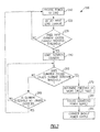
- Figure 2 schematically illustrates a method 200 for operation of the short circuit detection and protection scheme of Figure 1 .
- the method 200 provides power to the load 140 from the primary power supply 110 in the "provide power to load” step 210.
- the current sensor 170 measures the input load current and reports the measured current to the controller 160 in a "detect input load current” step 220.
- the controller 160 determines if the input load current exceeds a predefined current magnitude threshold in a "does input current exceed threshold” step 230. If the current magnitude threshold is not exceeded, the method restarts at the "provide power to load” step 210.
- the controller 160 starts a duration counter in a "start duration counter” step 240.
- the duration counter can be a software counter that determines how long the input load current has exceeded the current magnitude threshold.
- the controller 160 checks to see if the duration has exceeded an excess current duration threshold in a "does duration exceed threshold” step 250. If the excess current duration threshold is not exceeded, the controller 160 determines if the current threshold is still exceeded in an "is current magnitude threshold no longer exceeded” step 260. If the current magnitude threshold is no longer exceeded, the controller 160 restarts the method at the "provide power to load” step 210. A condition where the current magnitude threshold was temporarily exceeded, but the excess current duration threshold was not exceeded, indicates that there was a desirable high current pulse, and not a short circuit fault.
- the controller 160 continues to determine the duration of the excess current and returns to the "does duration exceed excess current duration threshold" step 250. If the "does duration exceed excess current duration threshold" step 250 determines that the duration of the excess current has exceeded the excess current duration threshold, the controller 160 determines that a short circuit fault is present in the power supply 110 in a "determine presence of a short circuit fault" step 270.
- the controller 160 isolates the primary power supply 110 and connects the backup power supply 120 to the input load power 142 using the procedure described above with regards to Figure 1 in an "isolate connected power supply” step 280.
- the controller 160 then connects the backup power supply 120 to the load 140 in a "connect backup power supply” step 290.
- the controller 160 can switch to the primary power supply 110, or completely isolate the power supplies 110, 120 from the load 140.
Abstract
Description
- The present application is directed to short circuit control for high current pulse power supplies.
- In applications using batteries or other stored power devices as a primary power supply, short circuit detection is typically included to determine if there is a short circuit fault in the power supply. Short circuit detection circuits can also isolate the power supply from a load when a short circuit is detected, thereby preventing the load from seeing excessive fault currents, which can interfere with load operations. Additionally, a backup power supply is often included to continue providing power to the load when the primary power supply is isolated from the load due to a short circuit fault. Systems using backup power supplies also include detection circuits for detecting a short circuit in the connected backup power supplies. The inclusion of additional detection circuits adds weight and cost to the construction of these systems.
- One standard short circuit detection method uses a current sensor combined with a controller to detect when the output current of the power supply exceeds a current threshold. When the output current exceeds the current threshold, the controller determines that a short circuit is present and isolates the power supply. The threshold is set at an expected short circuit current that is higher than the current used for standard operations.
- Disclosed is a method for controlling a high current pulse power supply. The method for detecting a load current uses a current sensor, and isolates a power source from a load when the load current exceeds a current magnitude threshold for a duration that is greater than an excess current duration threshold.
- Also disclosed is a power supply circuit having a controller electrically coupled to a switch driver. The power supply circuit also has a plurality of power channels, with each of the power channels connecting one of multiple power sources to a load power input and each of the power channels is electrically coupled to the switch driver. The power supply circuit also has a current sensor connected to the load power input and to the controller. The current sensor is capable of detecting a load input current and communicating the load input current to the controller.
- These and other features of the present disclosure can be best understood from the following specification and drawings, the following of which is a brief description.
-
-
Figure 1 schematically illustrates a power supply circuit for an electrical system having a primary and a backup power supply, and a short circuit detection scheme. -
Figure 2 is a flowchart demonstrating a method for detecting a short circuit in a high current pulse power supply system. - Some electrical systems operate using high magnitude current pulses. In such systems, the expected short circuit current can be lower than the magnitude of the high magnitude current pulses. Known short circuit detection circuits can result in false short circuit detections when a desired current has a pulse magnitude that exceeds an expected short circuit current.
-
Figure 1 schematically illustrates a high current pulsepower supply circuit 100. Thepower supply circuit 100 includes aprimary power supply 110 and a secondary (backup)power supply 120. Each of thepower supplies output power line 112, 122 which connects to acorresponding switching circuit 130 and may be any known type of power source. In one example, each of thepower supplies output power line 112, 122 and theswitching circuit 130 is referred to as apower channel 116, 126. Each of theswitching circuits 130 is capable of connecting the correspondingoutput power line 112, 122 to aload power input 142 that provides power to aload 140. Theswitching circuits 130 are controlled by aswitch driver 150, which is, in turn, controlled by a microcontroller 160 (alternately referred to as the controller 160). Acurrent sensor 170 monitors the current flowing into theload 140 on theload power input 142, and provides a control signal 172 to themicrocontroller 160, thereby providing the magnitude of the current flowing into theload 140 to themicrocontroller 160. Each of thepower supplies control connection microcontroller 160. Thecontrol connections controller 160 to detect power supply statistics, such as remaining power. Thecontroller 160 can also control the power output from thepower supplies - In standard operation each
power supply load 140 via apower channel 116, 126. Theswitching device 130 within eachpower channel 116, 126 is configured such that it is capable of interrupting theoutput power line 112, 122. Each of thepower supplies load power input 142 by itscorresponding power channel 116, 126, thereby allowing thecontroller 160 to isolate anypower supply - When the
load 140 requires a periodic high current load spike for normal operations, standard short circuit detection techniques will falsely trip on each current spike, and are therefore inadequate, Instead, thecontroller 160, illustrated inFigure 1 , utilizescurrent sensor 170 and a pair of current thresholds to determine when a short circuit exists. By way of example, thecurrent sensor 170 can be a Hall Effect sensor. - The
current sensor 170 detects the magnitude of the current at theload power input 142 and determines if the current exceeds a current magnitude threshold. The current magnitude threshold is set at an expected short circuit output current, and is tripped whenever the expected short circuit output current is exceeded. When the current magnitude threshold is exceeded, thecontroller 160 determines how long the current threshold has been exceeded, and compares the duration that the current magnitude threshold has been exceeded to an excess current duration threshold. Thecontroller 160 determines that a short circuit fault is present when both the current magnitude threshold and the duration threshold are exceeded. In this way, thecontroller 160 can distinguish between desirable high current load spikes that exceed the expected short circuit current of thepower supply power supply load 140. - By locating the
current sensor 170 at the load input, thecontroller 160 detects the ongoing load current regardless of whichpower supply load 140. This configuration allows for a singlecurrent sensor 170 to be used to control all of thepower supplies load 140 at a given time. Alternately, acurrent sensor 170 can be located at each of thepower supply outputs 112, 122, with thecontroller 160 having a dedicated controller input for eachcurrent sensor 170. - In the example of
Figure 1 , thecontroller 160 is a programmable microcontroller that has a computer readable medium capable of storing instructions for performing the method described below with regards toFigure 2 . Theprogrammable microcontroller 160 allows a user to modify the current and duration thresholds based on the power needs of the connectedload 140. A programmable controller allows the same control scheme to be used if thepower supplies controller 160 is programmed to have a high current magnitude threshold, and an extremely low duration threshold. Alternately, if the load requires a profile having high current, medium length, pulses thecontroller 160 is programmed to have a high current threshold and a medium length duration threshold. - The
switching mechanisms 130 illustrated inFigure 1 can be any known switching device capable of electrically isolating the connectedpower supplies exemplary switching device 130, is an array of MOSFETs (metal-oxide-semiconductor field-effect transistor) and diodes configured according to known principles to form a MOSFET/dual diode array switch. The MOSFET/dual diode arrays receive a control input from theswitch gate driver 150 that is either high or low. A high input places the array in an "on" mode and provides a connection between thepower supply output 112, 122 and theinput load power 142. A low input places the array in an "off" state that electrically isolates thepower supply output 112, 122 from theinput load power 142. It is understood that additional primary or backup power supplies can be added to the high current pulsepower supply circuit 100 by addingadditional switches 130, with eachswitch 130 controlling the connection of one additional primary or backup power supply. Furthermore, it is additionally understood that other types of switching devices can operate using a similar control scheme, and fall within this disclosure. -
Figure 2 schematically illustrates amethod 200 for operation of the short circuit detection and protection scheme ofFigure 1 . Initially themethod 200 provides power to theload 140 from theprimary power supply 110 in the "provide power to load"step 210. Thecurrent sensor 170 measures the input load current and reports the measured current to thecontroller 160 in a "detect input load current"step 220. Thecontroller 160 then determines if the input load current exceeds a predefined current magnitude threshold in a "does input current exceed threshold"step 230. If the current magnitude threshold is not exceeded, the method restarts at the "provide power to load"step 210. - If the current magnitude threshold is exceeded, the
controller 160 starts a duration counter in a "start duration counter"step 240. The duration counter can be a software counter that determines how long the input load current has exceeded the current magnitude threshold. Thecontroller 160 checks to see if the duration has exceeded an excess current duration threshold in a "does duration exceed threshold"step 250. If the excess current duration threshold is not exceeded, thecontroller 160 determines if the current threshold is still exceeded in an "is current magnitude threshold no longer exceeded"step 260. If the current magnitude threshold is no longer exceeded, thecontroller 160 restarts the method at the "provide power to load"step 210. A condition where the current magnitude threshold was temporarily exceeded, but the excess current duration threshold was not exceeded, indicates that there was a desirable high current pulse, and not a short circuit fault. - If the current magnitude threshold is still exceeded, the
controller 160 continues to determine the duration of the excess current and returns to the "does duration exceed excess current duration threshold"step 250. If the "does duration exceed excess current duration threshold"step 250 determines that the duration of the excess current has exceeded the excess current duration threshold, thecontroller 160 determines that a short circuit fault is present in thepower supply 110 in a "determine presence of a short circuit fault"step 270. - Once a short circuit fault has been detected, the
controller 160 isolates theprimary power supply 110 and connects thebackup power supply 120 to theinput load power 142 using the procedure described above with regards toFigure 1 in an "isolate connected power supply"step 280. Thecontroller 160 then connects thebackup power supply 120 to theload 140 in a "connect backup power supply"step 290. Alternately, if thebackup power supply 120 is currently connected when the short circuit fault is detected, thecontroller 160 can switch to theprimary power supply 110, or completely isolate the power supplies 110, 120 from theload 140. - It is understood that one of skill in the art can reconfigure the above described method to accommodate a single load having multiple power supplies beyond a primary power supply and a backup power supply,
- Although an example has been disclosed, a worker of ordinary skill in this art would recognize that certain modifications would come within the scope of this disclosure. For that reason, the following claims define the true scope of the invention.
Claims (15)
- A method for controlling a high current pulse power supply comprising the steps of:detecting a load current using a current sensor (170); andisolating a power source (110, 120) from a load (140) when said load current exceeds a current magnitude threshold for a duration greater than an excess current duration threshold.
- The method of claim 1, wherein said step of isolating said power source from said load further comprises the step of setting a first switching component to off, thereby isolating a primary power supply from a load power input.
- The method of claim 2, wherein said step of isolating said power source from said load further comprises the step of setting a second switching component to on, thereby connecting a backup power supply to said load power input.
- The method of claim 3, wherein said step of connecting said backup power supply to said load power input is performed after said step of isolating said primary power supply from said load power input, thereby preventing multiple power supplies from being connected to the load simultaneously.
- The method of claim 1, wherein said step of detecting said load current comprises sensing the load current on the load power input line using a Hall Effect current sensor.
- The method of claim 1, wherein said step of isolating said power source from said load when said load current exceeds said current magnitude threshold for said duration greater than said excess current duration threshold further comprises a controller (160) starting a duration counter when said current magnitude exceeds said current magnitude threshold.
- The method of claim 6, wherein said step of isolating said power source from said load when said load current exceeds said current magnitude threshold for said duration greater than said excess current duration threshold further comprises comparing a duration of said duration counter to said excess current duration threshold, thereby determining when said load current exceeds the current magnitude threshold for said duration greater than the excess current duration.
- The method of claim 6, wherein said duration counter comprises a controller software module.
- The method of claim 1, wherein said excess current duration threshold is at least a desired current pulse duration.
- A power supply circuit comprising:a controller (160) electrically coupled to a switch driver (130);a plurality of power channels (116, 126), each of said power channels connecting one of a plurality of power sources (110, 120) to a load power input and being coupled to said switch driver; anda current sensor (170) connected to said load power input and to said controller, such that said current sensor is capable of detecting a load input current and communicating said load input current to said controller.
- The power supply circuit of claim 10, wherein each of said power channels comprises a power supply output power line and a power switch capable of interrupting said power supply output power line.
- The power supply circuit of claim 11, wherein each of said power switches comprises a metal-oxide-semiconductor field-effect transistor (MOSFET) / dual diode array.
- The power supply circuit of claim 10, wherein said controller comprises a programmable microcontroller, and wherein said programmable microcontroller further comprises a computer readable medium storing instructions for causing the controller to performing the steps of detecting a load current using a current sensor and isolating a power source from a load when a load current exceeds a current magnitude threshold for a duration greater than an excess current duration threshold.
- The power supply circuit of claim 13, wherein said programmable microcontroller further comprises a software duration counter.
- The power supply circuit of claim 10, wherein each of said power supplies is electrically coupled to said controller via a control connection, thereby allowing said controller to control each of said power supplies.
Applications Claiming Priority (1)
| Application Number | Priority Date | Filing Date | Title |
|---|---|---|---|
| US12/887,559 US20120072739A1 (en) | 2010-09-22 | 2010-09-22 | Short circuit control for high current pulse power supply |
Publications (2)
| Publication Number | Publication Date |
|---|---|
| EP2434602A2 true EP2434602A2 (en) | 2012-03-28 |
| EP2434602A3 EP2434602A3 (en) | 2012-04-25 |
Family
ID=44785408
Family Applications (1)
| Application Number | Title | Priority Date | Filing Date |
|---|---|---|---|
| EP20110181658 Ceased EP2434602A3 (en) | 2010-09-22 | 2011-09-16 | Short circuit control for high current pulse power supply |
Country Status (9)
| Country | Link |
|---|---|
| US (1) | US20120072739A1 (en) |
| EP (1) | EP2434602A3 (en) |
| JP (1) | JP2012070620A (en) |
| KR (1) | KR20120031125A (en) |
| AU (1) | AU2011218782B2 (en) |
| CA (2) | CA2749451C (en) |
| IL (1) | IL215198B (en) |
| TW (1) | TWI502853B (en) |
| ZA (1) | ZA201105816B (en) |
Cited By (1)
| Publication number | Priority date | Publication date | Assignee | Title |
|---|---|---|---|---|
| CN107431347A (en) * | 2015-04-10 | 2017-12-01 | Abb瑞士股份有限公司 | Method and apparatus for the energy supply to low-voltage load |
Families Citing this family (3)
| Publication number | Priority date | Publication date | Assignee | Title |
|---|---|---|---|---|
| US9075595B2 (en) | 2012-08-30 | 2015-07-07 | Dell Products L.P. | Power excursion warning system |
| US9348395B2 (en) * | 2012-10-15 | 2016-05-24 | Dell Products L.P. | Power demand reduction system |
| US11668761B2 (en) * | 2021-10-06 | 2023-06-06 | Dell Products, L.P. | Adaptive short circuit detection system and method for an information handling system (IHS) |
Family Cites Families (18)
| Publication number | Priority date | Publication date | Assignee | Title |
|---|---|---|---|---|
| US4432031A (en) * | 1982-05-03 | 1984-02-14 | General Electric Company | Method for overcurrent protection |
| US4533836A (en) * | 1983-01-12 | 1985-08-06 | Pacific Electro Dynamics, Inc. | Multiple voltage switching power supply having output voltage limiting |
| US4524412A (en) * | 1983-06-06 | 1985-06-18 | At&T Bell Laboratories | Peak current controlled converter with additional current threshold control level to limit current tailout during overload conditions |
| JPH0686481A (en) * | 1992-08-31 | 1994-03-25 | Nec Eng Ltd | Backup power supply circuit |
| JPH08149684A (en) * | 1994-11-22 | 1996-06-07 | Fujitsu Ltd | Overcurrent interrupter for feeder line |
| US5579197A (en) * | 1995-01-24 | 1996-11-26 | Best Power Technology, Incorporated | Backup power system and method |
| JPH08254553A (en) * | 1995-03-16 | 1996-10-01 | Sumitomo Wiring Syst Ltd | Overcurrent detector |
| US6130813A (en) * | 1999-01-11 | 2000-10-10 | Dell U.S.A., L.P. | Protection circuit for electronic devices |
| US6329796B1 (en) * | 2000-07-25 | 2001-12-11 | O2 Micro International Limited | Power management circuit for battery systems |
| US6590757B2 (en) * | 2001-09-28 | 2003-07-08 | Eaton Corporation | Method and apparatus for detecting and suppressing a parallel arc fault |
| JP4359032B2 (en) * | 2002-10-08 | 2009-11-04 | 株式会社リコー | Power supply device and digital camera equipped with the power supply device |
| US7382595B2 (en) * | 2005-05-25 | 2008-06-03 | Electronic Theatre Controls, Inc. | Low voltage overcurrent protection for solid state switching system |
| US8659856B2 (en) * | 2005-12-09 | 2014-02-25 | Hamilton Sundstrand Corporation | DC arc fault detection and protection |
| JP4556929B2 (en) * | 2006-09-07 | 2010-10-06 | 日立工機株式会社 | Electric tool |
| US7652862B2 (en) * | 2006-09-29 | 2010-01-26 | Avocent Huntsville Corporation | Hardware based over-current protection circuitry for power distribution systems |
| TWI328923B (en) * | 2007-01-17 | 2010-08-11 | Ching Tsai Pan | Power supply and charger for series-parallel loosely coupled inductive power transfer system |
| JP5044448B2 (en) * | 2008-03-03 | 2012-10-10 | ルネサスエレクトロニクス株式会社 | Power switch circuit |
| US7893560B2 (en) * | 2008-09-12 | 2011-02-22 | Nellcor Puritan Bennett Llc | Low power isolation design for a multiple sourced power bus |
-
2010
- 2010-09-22 US US12/887,559 patent/US20120072739A1/en not_active Abandoned
-
2011
- 2011-08-08 ZA ZA2011/05816A patent/ZA201105816B/en unknown
- 2011-08-09 TW TW100128417A patent/TWI502853B/en not_active IP Right Cessation
- 2011-08-17 CA CA2749451A patent/CA2749451C/en not_active Expired - Fee Related
- 2011-08-17 CA CA2967404A patent/CA2967404C/en not_active Expired - Fee Related
- 2011-09-06 AU AU2011218782A patent/AU2011218782B2/en not_active Ceased
- 2011-09-07 KR KR20110090449A patent/KR20120031125A/en active Search and Examination
- 2011-09-14 JP JP2011200066A patent/JP2012070620A/en active Pending
- 2011-09-16 EP EP20110181658 patent/EP2434602A3/en not_active Ceased
- 2011-09-18 IL IL215198A patent/IL215198B/en active IP Right Grant
Non-Patent Citations (1)
| Title |
|---|
| None |
Cited By (2)
| Publication number | Priority date | Publication date | Assignee | Title |
|---|---|---|---|---|
| CN107431347A (en) * | 2015-04-10 | 2017-12-01 | Abb瑞士股份有限公司 | Method and apparatus for the energy supply to low-voltage load |
| CN107431347B (en) * | 2015-04-10 | 2019-04-09 | Abb瑞士股份有限公司 | Method and apparatus for the energy supply to low-voltage load |
Also Published As
| Publication number | Publication date |
|---|---|
| TW201223078A (en) | 2012-06-01 |
| IL215198B (en) | 2018-02-28 |
| AU2011218782A1 (en) | 2012-04-05 |
| JP2012070620A (en) | 2012-04-05 |
| CA2749451A1 (en) | 2012-03-22 |
| CA2749451C (en) | 2017-07-04 |
| TWI502853B (en) | 2015-10-01 |
| ZA201105816B (en) | 2012-04-25 |
| CA2967404C (en) | 2019-04-30 |
| KR20120031125A (en) | 2012-03-30 |
| AU2011218782B2 (en) | 2014-07-17 |
| EP2434602A3 (en) | 2012-04-25 |
| US20120072739A1 (en) | 2012-03-22 |
| CA2967404A1 (en) | 2012-03-22 |
| IL215198A0 (en) | 2012-02-29 |
Similar Documents
| Publication | Publication Date | Title |
|---|---|---|
| US11075623B2 (en) | Method for controlling a direct current switch, direct current switch, and DC voltage system | |
| CN104283421B (en) | Fault detect in hot plug application | |
| US10110219B2 (en) | Driving apparatus | |
| EP2887546B1 (en) | Monitoring method and device for power semiconductor switch | |
| US10804891B2 (en) | Driving device | |
| US8922258B2 (en) | Switching element driver IC and switching element driver device equipped with the same | |
| US10809285B2 (en) | Current detection circuit and current detection method of semiconductor element | |
| CN105099145A (en) | Gate drive unit and method for short circuit protection for a power switch | |
| EP3010128B1 (en) | Electronic circuit | |
| KR101790134B1 (en) | Error diagnosis method for inverter | |
| US9857428B2 (en) | Monitoring device and monitoring method for a switching element | |
| CA2749451C (en) | Short circuit control for high current pulse power supply | |
| JP2013106464A (en) | Semiconductor device | |
| CN106797114A (en) | For the circuit and method of detection switch transistor short trouble | |
| US10530250B2 (en) | Multiphase converter | |
| JP2018007551A (en) | Power supply apparatus with soft-start and protection | |
| WO2008021440A2 (en) | Buck converter fault detection method | |
| JP6459519B2 (en) | Protection device for power converter | |
| US9913346B1 (en) | Surge protection system and method for an LED driver | |
| CN107181235A (en) | Fault control for high-current pulse power supply | |
| SG190464A1 (en) | Short circuit control for high current pulse power supply | |
| CN107134754B (en) | Output overvoltage protection method and device of power supply parallel operation system | |
| EP3048713B1 (en) | Power supply apparatus | |
| EP2690784B1 (en) | Self-test of over-current fault detection | |
| EP3059842A1 (en) | Method of protecting a semiconductor device |
Legal Events
| Date | Code | Title | Description |
|---|---|---|---|
| PUAL | Search report despatched |
Free format text: ORIGINAL CODE: 0009013 |
|
| PUAI | Public reference made under article 153(3) epc to a published international application that has entered the european phase |
Free format text: ORIGINAL CODE: 0009012 |
|
| AK | Designated contracting states |
Kind code of ref document: A2 Designated state(s): AL AT BE BG CH CY CZ DE DK EE ES FI FR GB GR HR HU IE IS IT LI LT LU LV MC MK MT NL NO PL PT RO RS SE SI SK SM TR |
|
| AX | Request for extension of the european patent |
Extension state: BA ME |
|
| AK | Designated contracting states |
Kind code of ref document: A3 Designated state(s): AL AT BE BG CH CY CZ DE DK EE ES FI FR GB GR HR HU IE IS IT LI LT LU LV MC MK MT NL NO PL PT RO RS SE SI SK SM TR |
|
| AX | Request for extension of the european patent |
Extension state: BA ME |
|
| RIC1 | Information provided on ipc code assigned before grant |
Ipc: H02J 1/10 20060101ALI20120320BHEP Ipc: H02H 3/093 20060101AFI20120320BHEP |
|
| 17P | Request for examination filed |
Effective date: 20121008 |
|
| 17Q | First examination report despatched |
Effective date: 20160525 |
|
| STAA | Information on the status of an ep patent application or granted ep patent |
Free format text: STATUS: THE APPLICATION HAS BEEN REFUSED |
|
| 18R | Application refused |
Effective date: 20200622 |