EP2455014A1 - Implantable device for preventive or interventive treatment of femur fractures, associated ancillary device - Google Patents
Implantable device for preventive or interventive treatment of femur fractures, associated ancillary device Download PDFInfo
- Publication number
- EP2455014A1 EP2455014A1 EP10306265A EP10306265A EP2455014A1 EP 2455014 A1 EP2455014 A1 EP 2455014A1 EP 10306265 A EP10306265 A EP 10306265A EP 10306265 A EP10306265 A EP 10306265A EP 2455014 A1 EP2455014 A1 EP 2455014A1
- Authority
- EP
- European Patent Office
- Prior art keywords
- implant
- femur
- preventive
- fractures
- curative treatment
- Prior art date
- Legal status (The legal status is an assumption and is not a legal conclusion. Google has not performed a legal analysis and makes no representation as to the accuracy of the status listed.)
- Granted
Links
- 230000003449 preventive effect Effects 0.000 title claims description 17
- 206010016454 Femur fracture Diseases 0.000 title claims 6
- 239000007943 implant Substances 0.000 claims abstract description 132
- 210000000689 upper leg Anatomy 0.000 claims abstract description 44
- 206010017076 Fracture Diseases 0.000 claims description 29
- 210000000988 bone and bone Anatomy 0.000 claims description 27
- 238000009109 curative therapy Methods 0.000 claims description 14
- 238000013519 translation Methods 0.000 claims description 5
- 230000035515 penetration Effects 0.000 claims description 4
- 239000007787 solid Substances 0.000 claims description 4
- 238000013459 approach Methods 0.000 claims description 3
- 230000011712 cell development Effects 0.000 claims description 2
- 239000007972 injectable composition Substances 0.000 claims description 2
- 210000001519 tissue Anatomy 0.000 claims description 2
- 239000000463 material Substances 0.000 abstract description 14
- 210000002436 femur neck Anatomy 0.000 abstract description 10
- 230000009969 flowable effect Effects 0.000 abstract 2
- 208000010392 Bone Fractures Diseases 0.000 description 8
- 210000002414 leg Anatomy 0.000 description 7
- 210000004394 hip joint Anatomy 0.000 description 6
- 238000002513 implantation Methods 0.000 description 6
- 239000003351 stiffener Substances 0.000 description 5
- 238000005553 drilling Methods 0.000 description 4
- 238000003780 insertion Methods 0.000 description 4
- 230000037431 insertion Effects 0.000 description 4
- 230000035939 shock Effects 0.000 description 4
- 238000005452 bending Methods 0.000 description 3
- 239000004568 cement Substances 0.000 description 3
- 230000001054 cortical effect Effects 0.000 description 3
- 238000002347 injection Methods 0.000 description 3
- 239000007924 injection Substances 0.000 description 3
- 239000000203 mixture Substances 0.000 description 3
- 210000004872 soft tissue Anatomy 0.000 description 3
- 238000001356 surgical procedure Methods 0.000 description 3
- 206010020100 Hip fracture Diseases 0.000 description 2
- 208000006735 Periostitis Diseases 0.000 description 2
- 210000000588 acetabulum Anatomy 0.000 description 2
- 238000007596 consolidation process Methods 0.000 description 2
- 230000007423 decrease Effects 0.000 description 2
- 210000003275 diaphysis Anatomy 0.000 description 2
- 238000011065 in-situ storage Methods 0.000 description 2
- 208000014674 injury Diseases 0.000 description 2
- 230000003902 lesion Effects 0.000 description 2
- 210000000528 lesser trochanter Anatomy 0.000 description 2
- 210000003205 muscle Anatomy 0.000 description 2
- 210000004197 pelvis Anatomy 0.000 description 2
- 210000003460 periosteum Anatomy 0.000 description 2
- 230000008733 trauma Effects 0.000 description 2
- 208000001132 Osteoporosis Diseases 0.000 description 1
- 239000004696 Poly ether ether ketone Substances 0.000 description 1
- RTAQQCXQSZGOHL-UHFFFAOYSA-N Titanium Chemical compound [Ti] RTAQQCXQSZGOHL-UHFFFAOYSA-N 0.000 description 1
- 239000004480 active ingredient Substances 0.000 description 1
- 238000004873 anchoring Methods 0.000 description 1
- 230000037182 bone density Effects 0.000 description 1
- 230000006835 compression Effects 0.000 description 1
- 238000007906 compression Methods 0.000 description 1
- 230000034994 death Effects 0.000 description 1
- 231100000517 death Toxicity 0.000 description 1
- 210000002082 fibula Anatomy 0.000 description 1
- 210000000527 greater trochanter Anatomy 0.000 description 1
- 238000010237 hybrid technique Methods 0.000 description 1
- 229910052588 hydroxylapatite Inorganic materials 0.000 description 1
- 238000009434 installation Methods 0.000 description 1
- 230000010354 integration Effects 0.000 description 1
- 238000002955 isolation Methods 0.000 description 1
- 210000003127 knee Anatomy 0.000 description 1
- 230000000877 morphologic effect Effects 0.000 description 1
- 230000002232 neuromuscular Effects 0.000 description 1
- XYJRXVWERLGGKC-UHFFFAOYSA-D pentacalcium;hydroxide;triphosphate Chemical compound [OH-].[Ca+2].[Ca+2].[Ca+2].[Ca+2].[Ca+2].[O-]P([O-])([O-])=O.[O-]P([O-])([O-])=O.[O-]P([O-])([O-])=O XYJRXVWERLGGKC-UHFFFAOYSA-D 0.000 description 1
- 239000004033 plastic Substances 0.000 description 1
- 229920002530 polyetherether ketone Polymers 0.000 description 1
- 229920000642 polymer Polymers 0.000 description 1
- 238000011084 recovery Methods 0.000 description 1
- 239000012779 reinforcing material Substances 0.000 description 1
- 230000000717 retained effect Effects 0.000 description 1
- 238000010079 rubber tapping Methods 0.000 description 1
- 238000007789 sealing Methods 0.000 description 1
- 239000003566 sealing material Substances 0.000 description 1
- 125000006850 spacer group Chemical group 0.000 description 1
- 230000000087 stabilizing effect Effects 0.000 description 1
- 229910001220 stainless steel Inorganic materials 0.000 description 1
- 239000010935 stainless steel Substances 0.000 description 1
- 238000005728 strengthening Methods 0.000 description 1
- 229910052719 titanium Inorganic materials 0.000 description 1
- 239000010936 titanium Substances 0.000 description 1
- 230000000472 traumatic effect Effects 0.000 description 1
Images


Classifications
-
- A—HUMAN NECESSITIES
- A61—MEDICAL OR VETERINARY SCIENCE; HYGIENE
- A61B—DIAGNOSIS; SURGERY; IDENTIFICATION
- A61B17/00—Surgical instruments, devices or methods, e.g. tourniquets
- A61B17/56—Surgical instruments or methods for treatment of bones or joints; Devices specially adapted therefor
- A61B17/58—Surgical instruments or methods for treatment of bones or joints; Devices specially adapted therefor for osteosynthesis, e.g. bone plates, screws, setting implements or the like
- A61B17/68—Internal fixation devices, including fasteners and spinal fixators, even if a part thereof projects from the skin
- A61B17/74—Devices for the head or neck or trochanter of the femur
- A61B17/742—Devices for the head or neck or trochanter of the femur having one or more longitudinal elements oriented along or parallel to the axis of the neck
-
- A—HUMAN NECESSITIES
- A61—MEDICAL OR VETERINARY SCIENCE; HYGIENE
- A61B—DIAGNOSIS; SURGERY; IDENTIFICATION
- A61B17/00—Surgical instruments, devices or methods, e.g. tourniquets
- A61B17/16—Bone cutting, breaking or removal means other than saws, e.g. Osteoclasts; Drills or chisels for bones; Trepans
- A61B17/17—Guides or aligning means for drills, mills, pins or wires
- A61B17/1721—Guides or aligning means for drills, mills, pins or wires for applying pins along or parallel to the axis of the femoral neck
-
- A—HUMAN NECESSITIES
- A61—MEDICAL OR VETERINARY SCIENCE; HYGIENE
- A61B—DIAGNOSIS; SURGERY; IDENTIFICATION
- A61B17/00—Surgical instruments, devices or methods, e.g. tourniquets
- A61B17/56—Surgical instruments or methods for treatment of bones or joints; Devices specially adapted therefor
- A61B17/58—Surgical instruments or methods for treatment of bones or joints; Devices specially adapted therefor for osteosynthesis, e.g. bone plates, screws, setting implements or the like
- A61B17/68—Internal fixation devices, including fasteners and spinal fixators, even if a part thereof projects from the skin
- A61B17/70—Spinal positioners or stabilisers ; Bone stabilisers comprising fluid filler in an implant
- A61B17/7097—Stabilisers comprising fluid filler in an implant, e.g. balloon; devices for inserting or filling such implants
- A61B17/7098—Stabilisers comprising fluid filler in an implant, e.g. balloon; devices for inserting or filling such implants wherein the implant is permeable or has openings, e.g. fenestrated screw
-
- A—HUMAN NECESSITIES
- A61—MEDICAL OR VETERINARY SCIENCE; HYGIENE
- A61F—FILTERS IMPLANTABLE INTO BLOOD VESSELS; PROSTHESES; DEVICES PROVIDING PATENCY TO, OR PREVENTING COLLAPSING OF, TUBULAR STRUCTURES OF THE BODY, e.g. STENTS; ORTHOPAEDIC, NURSING OR CONTRACEPTIVE DEVICES; FOMENTATION; TREATMENT OR PROTECTION OF EYES OR EARS; BANDAGES, DRESSINGS OR ABSORBENT PADS; FIRST-AID KITS
- A61F2/00—Filters implantable into blood vessels; Prostheses, i.e. artificial substitutes or replacements for parts of the body; Appliances for connecting them with the body; Devices providing patency to, or preventing collapsing of, tubular structures of the body, e.g. stents
- A61F2/02—Prostheses implantable into the body
- A61F2/30—Joints
- A61F2/32—Joints for the hip
- A61F2/36—Femoral heads ; Femoral endoprostheses
Definitions
- the present invention relates to an implantable device for the preventive or curative treatment of fractures of the femur, more particularly of the hip joint.
- the invention covers the associated ancillary.
- the bones are formed in the inner part of a spongy material having a high degree of porosity surrounded by a much more rigid and mechanically resistant material called cortical cortex or bone.
- cortical cortex or bone a much more rigid and mechanically resistant material
- the hip joint is a joint subject to intense efforts.
- the femur extends from the pelvis to the knee.
- This femur comprises a coxofemoral joint consisting of a femoral head, a neck, small and large trochanters that connect the head and neck of the femur to the body of the long bone, the diaphysis.
- This bone is the longest and most solid human body since it takes the weight of the body.
- the proximal end of the femur is particularly subject to osteoporosis phenomena, which greatly reduces the mechanical strength of this proximal assembly.
- the fracture occurs particularly in the two areas of the femoral neck and in the trochanteric regions.
- fractures are described as sub-capital fracture of the femoral neck, transcervical fracture of the femoral neck, pertrochanteric fracture, subtrochanteric fracture or fracture of the small trochanter.
- the neuromuscular response decreases so that the muscles responsible for resuming sudden efforts and dissipating the peak of kinetic energy generated no longer provide the necessary compensation.
- This fragility is generated by the particular geometry of the femoral head supported by the femoral neck, offset from the longitudinal axis of the body of the long bone of the femur.
- the means used in the prior art is to repair the fracture, reducing the fracture if necessary, stabilizing and fixing the broken part.
- the known treatment consists in using systems composed of intramedullary nails and compression screws placed in the femoral head.
- the known surgery also uses systems combining plates and pressure screws or even cement injection in the areas concerned.
- the two tubes are not linked together, the second tube being used as a guide.
- the patent application relates to a biocompatible tip of a specific material so as to ensure satisfactory anchoring of the first proximal implant along the longitudinal axis of the neck.
- This device is suitable for fracture repair but no application is envisaged in the preventive treatment of fractures.
- the present invention is particularly aimed at a preventive application of resistance strengthening. of this femoral head in subjects at risk.
- the present invention proposes to strengthen the mechanical strength of the hip joint to prevent fractures or lesions of the femoral head, femoral neck or trochanteric region.
- the present invention uses a set of two intersecting implants and means for securing the two implants together at the point of intersection.
- these two implants are both secant with the longitudinal axis of the body of the long bone.
- the point of intersection is substantially in the area of the foot of the pass.
- the first implant is oriented along the axis of the neck and the second more inclined through the point of intersection of the two implants.
- the first implant has a stiffener function and the second implant has a leg function.
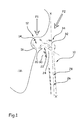
- FIG. 1 On the figure 1 the proximal portion of a femur 10 is shown with its coxofemoral joint 12.
- the femur represented is the femur of the individual's left leg.
- This articulation comprises a femoral head 14 adapted to cooperate with the acetabulum 16 of the pelvis 18, symbolized in broken lines.
- the femoral head 14 is carried by the proximal end of the neck 22 of the femur while the distal end 24 of the neck 22 of the femur is integral with the bone 28 along the femur, the diaphysis.
- the longitudinal axis of the neck 22 of the femur forms an angle ⁇ with the longitudinal axis XX 'of the bone 28 along the femur.
- the coxofemoral head further comprises trochanters, a small trochanter 30 and a greater trochanter 32, defining a trochanteric region 34.
- This coxofemoral articulation is subjected to severe mechanical constraints.
- This next F1 force is transmitted directly to the femoral head, substantially parallel to the longitudinal axis XX 'of the long bone of the femur.
- the bone material like any material, has an elastic limit and a plastic limit with an established breaking force, depending on the state of this bone material.
- FIG. figure 2 the general architecture of the device according to the present invention is shown in FIG. figure 2 .
- This implantable device comprises a first implant 36 and a second implant 38.
- These implants are generally tubular, hollow or solid, with a profile of revolution or not, with dimensions such that the length is much greater than the diameter.
- Both implants being secant at a point S, 40 with a fixed connection between the two implants, the right of the point S of intersection.
- These two implants 36, 38 are inclined and each have their longitudinal axis YY 'and ZZ' inclined relative to the longitudinal axis XX ' of the long bone of the femur, that is to say that neither of the two axes YY 'and ZZ' are not confused with this longitudinal axis XX ' .
- the first implant 36 has its longitudinal axis YY ' which makes an angle ⁇ with the axis XX' , substantially equal to ⁇
- the second implant has its longitudinal axis ZZ ' which makes an angle ⁇ with this same axis XX' .
- ⁇ is of an angular value greater than that of ⁇ .
- angles are considered with the coxofemoral head in the upper part, on the left femur, clockwise, 0 ° being in the upper part of the axis XX ' , side X and 180 ° side X'.
- the angles ⁇ and ⁇ are between 91 and 179 °.
- angles ⁇ and ⁇ are between 181 and 269 °.
- the axis YY ' is substantially coincident with the longitudinal axis of the neck of the femur.
- This first implant 36 therefore has a stiffening role linking the femoral head 14, the neck 22 of the femur and the long bone 28 of the femur. It increases the resistance to bending.
- This first implant 36 must be positioned so that its distal end Y comes into the femoral head without protruding beyond the cortical part so as not to hinder the movements of the surface of the femoral head in the acetabulum that receives it.
- This cortical thickness is even guaranteeing a possible abutment to perforation by the implant in case of significant shock.
- the proximal end Y 'of this first implant passes through the cortex and can remain in slight projection, so as to be certain of a good recovery efforts.
- the first implant 36 works to bending, such a stiffener, the proximal end Y 'can be considered as an embedding, limited by the mere strength of the cortex that in this case, is very high since the resultant of the reaction is exerted in the plane of the bone.
- the first implant When the force is exerted along the arrow F2, the first implant also works to bend this time in its median part that is to say in flexion on two supports, one being the distal zone of the implant in the femoral head and the other support being the proximal area of the implant in the cortex.
- the invention proposes to increase even more significantly this mechanical strength by performing the architecture described above with the second implant 38 which provides the jamb function.
- This second implant 38 is therefore positioned by its proximal portion Z 'also in the cortex of the long bone of the femur at a point located at a distance farther from the hip joint.
- the distal end Z of the second implant is positioned at the intersection point S and forms the fixed link 40. The end can extend beyond if necessary.
- intersection point S is located approximately between the center portion of the first implant and the end Y distal
- a Y-shaped configuration is substantially obtained.
- the bending strength of the first implant is enhanced since the "flexible" portion receives a substantially middle portion of the leg, which shortens the lever arm of the portion between the middle portion and the proximal part.
- a pair of forces also occurs around the fixed point S.
- a majority of the force F1, exerted in the direction of the arrow F1 is taken up by the cortex because the balancing force of the couple is exerted in the plane of the cortex of the bone 26 along the femur in a direction opposite to F1, going to the coxofemoral articulation.
- the fixed link 40 is represented on the figure 4 as being a penetration of the first implant 36 in the second implant 38.
- the assembly provided is an elastic snap with pins. It could have been a lumen formed in the second implant 38 through which the first implant 36 passes without this changing the embodiment.
- the fixed link 40 represented on the figure 5 consists in a penetration of the second implant 38 in the first implant 36.
- a stop 42, formed on the second implant 38 ensures the locking and the stability of the connection to obtain the jamb function.
- the angle is given by the oblique drilling.
- the fixed link 40 according to a third general embodiment illustrated on the FIGS. 6A, 6B and 6C consists in providing a mechanical locking connection.
- the illustrated embodiment consists of a connection comprising a thread 44 carried by the second implant 38 and a tapped hole 46 formed in the body of the first implant 36.
- a ring 48 compensates for the angular difference and provide stable support.
- the ring is mounted free to rotate and is oriented to position relative to the other implant.
- the implants 36 and 38 may take any suitable form but in general, these implants are made from solid, hollow or partially hollow tubes.
- the section is of dimensions much smaller than the length.
- the diameter of the section is between 3 and 15 mm with a length of 50 to 150 mm.
- the section of these tubes can also take any form required by calculations or surgical requirements: circular, elliptical, square, hexagonal or star, threaded externally all or part of or a combination thereof.
- the implant can be tapered throughout its length.
- the adapted profile is chosen. If a screw is provided, the circular section of the implant to be screwed is required, while the multi-section for the first implant can be retained.
- each tube constituting an implant may also have orifices 50 opening outwards in the case of totally or partially hollow implants, as shown in FIG. figure 7 . These orifices allow injection of biocompatible cement-type injectable compositions from the accessible proximal end once the implant is in place. These compositions harden in situ.
- the distal end Y and Z is advantageously chamfered or rounded to facilitate progression at the introduction.
- the materials used are materials well known in surgery such as stainless steel, titanium, filled polymers such as polyether ether ketone with high mechanical strength or uncharged so as to approach the strength of the bone.
- the implant surface may also be coated or surface treated to improve biocompatibility, integration into bone, and tissue cell development, such as hydroxyapatite.
- the implants may be of variable length so as to adjust their length in situ.
- the telescopic assembly may consist of a two-part implant connected to each other by a threaded area.
- the first step illustrated on the figure 8A shows the introduction of a pin 52, closest to the central axis of the neck of the femur.
- the introduction is carried out under fluoroscopic control for example, after incision of the soft tissues and periosteum of the long bone of the femur.
- This pin is important and must be verified both in the frontal and sagittal plane.
- Figure 8B it is used a sextant 54 to ensure the positioning of the various approaches and implants 36 and 38 at the end of the intervention.
- This sextant 54 comprises a body 56 with a line of sight materialized by a first guide tube 58, along the axis of the pin 52 and thus the axis YY ' of the first implant to be put in place.
- This sextant further comprises a second line of sight materialized by a second guide tube 60, along the axis ZZ ' of the second implant to be put in place, as will be visible on the Figures 8D, 8E and 8F .
- Drilling is performed along the axis YY ' with the aid of a drill so as to then receive the first implant 36 in the housing 62 thus produced.
- the drill bit is guided by the guide tube 58.
- the depth of the drilling is controlled by the insertion length of the drill, always relative to the guide tube 58.
- the length of the housing 62 thus produced being known, the choice of the length and / or the adjustment of the length of the first implant 36 is performed by the practitioner.
- the first implant 36 is partially inserted, according to a first protocol.
- the implant 36 is mounted on a gripper 64 which is a tube of the diameter of the implant.
- the gripper 64 comprises means for removably fixing the implant 36 in rotation. These means comprise in this case a threaded end formed on the end of the implant 36 while the gripper 64 is provided at its proximal end with a tapping of conjugate profile.
- the implant 36 is thus removably attached to the gripper 64 but allowing the practitioner to act in translation.
- This gripper 64 is provided to cooperate with the sextant 56 and the first guide tube 58 to ensure continuity of alignment.
- an orientator 68 which is a rod of small diameter, coaxially mounted internally to the gripper 64, the pointer 68 being free in rotation and translation in the gripper 64.
- the distal end of the orientator 68 is provided with a tooth intended to fit into a notch of conjugated profile formed in the proximal part of the implant, thus allowing the practitioner to act in rotation when the orientator is totally introduced. Any other rotational drive means disconnectable between the gripper and the orientator can be envisaged.
- the orientator has a handle 66 to facilitate the maneuver by the practitioner. This partial insertion operation of the first implant 36 being performed according to the protocol adopted, the second implant 38 can then be put in place, according to another step of the protocol.
- the practitioner therefore proceeds to the incision of the soft tissues and the periosteum and then to the introduction of a spindle, as previously, pin which is introduced until it comes out into the housing 62 at the point of intersection S , and at the if necessary, this thanks to the geometry of the sextant.
- the second tube 60 for guiding the sextant makes it possible to follow the correct orientation angle and the alignment.
- a drill is made using a drill so as to generate a second housing 70 for receiving the second implant 38.
- the first implant 36 is introduced integrally into its final position as well. If necessary, it is possible to impact the orientator 68 and manipulate it in rotation to complete the introduction and complete insertion of the first implant 36 in its housing 62.
- the second implant 38 is introduced in turn, see figure 8F .
- the link 40 fixed at the intersection point S is of the screw type, for example, as illustrated in FIGS. Figures 6A to 6C then by means of the orientator 68 and its handle 66, the second implant 38 is rotated until the fixed link, screwed, is locked by complete screwing.
- the two implants are secured and positioned in the femur.
- the ancillary equipment can then be removed.
- the first implant can be introduced from its implementation, in full, in final position.
- the drilling of the second housing 70 is performed without arriving in the first housing 62 since it is occupied by the first implant 36.
- the second implant 38 is introduced in full and the introduction of the second implant pushes the soft tissue on the undrilled part of the housing until the connection with the first implant.
- the practitioner can proceed, as indicated in the foregoing description, to an injection of a biocompatible sealing and / or reinforcing material and / or treatment, by introducing into the injected composition of active ingredients.
Abstract
Description
La présente invention a pour objet un dispositif implantable pour le traitement préventif ou curatif de fractures du fémur, plus particulièrement de l'articulation coxofémorale.The present invention relates to an implantable device for the preventive or curative treatment of fractures of the femur, more particularly of the hip joint.
L'invention couvre l'ancillaire associé.The invention covers the associated ancillary.
De façon générale les os sont constitués dans la partie intérieure d'une matière spongieuse présentant un fort degré de porosité entourée d'une matière beaucoup plus rigide et résistante mécaniquement dite cortex ou os cortical. Dans le squelette, l'articulation de la hanche est une articulation soumise à des efforts intenses. Le fémur se prolonge du bassin jusqu'au genou.In general, the bones are formed in the inner part of a spongy material having a high degree of porosity surrounded by a much more rigid and mechanically resistant material called cortical cortex or bone. In the skeleton, the hip joint is a joint subject to intense efforts. The femur extends from the pelvis to the knee.
Ce fémur comprend une articulation coxofémorale composée d'une tête fémorale, d'un col, des petit et gros trochanters qui relient la tête et le col du fémur au corps de l'os long, la diaphyse.This femur comprises a coxofemoral joint consisting of a femoral head, a neck, small and large trochanters that connect the head and neck of the femur to the body of the long bone, the diaphysis.
Cet os est le plus long et le plus solide du corps humains puisqu'il reprend le poids du corps.This bone is the longest and most solid human body since it takes the weight of the body.
L'extrémité proximale du fémur est particulièrement soumise aux phénomènes d'ostéoporose, ce qui diminue fortement la résistance mécanique de cet ensemble proximal.The proximal end of the femur is particularly subject to osteoporosis phenomena, which greatly reduces the mechanical strength of this proximal assembly.
Ceci est particulièrement fréquent chez les sujets âgés.This is particularly common in elderly people.
De ce fait, la fracture se produit particulièrement dans les deux zones du col du fémur et dans les régions trochantériennes.As a result, the fracture occurs particularly in the two areas of the femoral neck and in the trochanteric regions.
On trouve les fractures dites : fracture sous capitale du col du fémur, fracture transcervicale du col du fémur, fracture pertrochantérienne, fracture soustrochantérienne ou fracture du petit trochanter.The so-called fractures are described as sub-capital fracture of the femoral neck, transcervical fracture of the femoral neck, pertrochanteric fracture, subtrochanteric fracture or fracture of the small trochanter.
Ces fractures sont la cause d'une majorité de décès parmi les personnes âgées, du fait des complications qu'elles engendrent.These fractures are the cause of a majority of deaths among the elderly, because of the complications that they generate.
On sait que, au-delà d'un certain âge, environ 50 ans, la masse osseuse et la densité osseuse peuvent diminuer dans certaines zones et notamment dans la zone de la tête fémorale tandis que les os longs voient leur résistance augmenter.It is known that, beyond a certain age, about 50 years, bone mass and bone density may decrease in some areas and especially in the area of the femoral head while the long bones are increasing in strength.
Parallèlement la réponse neuromusculaire diminue si bien que les muscles chargés de reprendre des efforts soudains et de dissiper le pic d'énergie cinétique généré n'apportent plus la compensation nécessaire.At the same time, the neuromuscular response decreases so that the muscles responsible for resuming sudden efforts and dissipating the peak of kinetic energy generated no longer provide the necessary compensation.
De ce fait, l'effort se concentre sur l'articulation coxofémorale fragilisée, ce qui conduit aux différents types de fractures ci-dessus évoquées, en fonction du type de choc, d'effort, de l'orientation, de la concentration et de très nombreux paramètres.As a result, the effort focuses on the weakened hip joint, which leads to the different types of fractures mentioned above, depending on the type of shock, effort, orientation, concentration and very many parameters.
Cette fragilité est engendrée par la géométrie particulière de cette tête fémorale supportée par le col du fémur, en déport par rapport à l'axe longitudinal du corps de l'os long du fémur.This fragility is generated by the particular geometry of the femoral head supported by the femoral neck, offset from the longitudinal axis of the body of the long bone of the femur.
Les moyens mis en oeuvre dans l'art antérieur consiste à réparer la fracture, en réduisant la fracture si nécessaire, en stabilisant et en fixant la partie cassée. Le traitement connu consiste à recourir à des systèmes composés de clous intra médullaires et de vis de compression placées dans la tête fémorale.The means used in the prior art is to repair the fracture, reducing the fracture if necessary, stabilizing and fixing the broken part. The known treatment consists in using systems composed of intramedullary nails and compression screws placed in the femoral head.
La chirurgie connue fait aussi appel à des systèmes combinant des plaques et des vis de pression ou même à l'injection de ciment dans les zones concernées.The known surgery also uses systems combining plates and pressure screws or even cement injection in the areas concerned.
De façon surprenante, on constate que l'art antérieur est très pauvre en ce qui concerne la prévention des fractures par augmentation de la résistance mécanique de la tête fémorale.Surprisingly, it is found that the prior art is very poor in preventing fractures by increasing the mechanical strength of the femoral head.
On peut citer un brevet
Il est aussi prévu la possibilité de doubler l'intervention par un second implant indépendant du premier, suivant une direction longitudinale suivant l'axe de l'os long constituant le fémur.It is also planned the possibility of doubling the intervention by a second implant independent of the first, in a longitudinal direction along the axis of the long bone constituting the femur.
Les deux tubes ne sont pas liés entre eux, le second tube étant utilisé comme un guidage.The two tubes are not linked together, the second tube being used as a guide.
La demande de brevet porte en effet sur un embout biocompatible en un matériau spécifique de façon à assurer un ancrage satisfaisant du premier implant proximal, suivant l'axe longitudinal du col.The patent application relates to a biocompatible tip of a specific material so as to ensure satisfactory anchoring of the first proximal implant along the longitudinal axis of the neck.
Ce dispositif est adapté pour la réparation de fracture mais il n'est prévu aucune application dans le traitement préventif des fractures.This device is suitable for fracture repair but no application is envisaged in the preventive treatment of fractures.
Si l'objet de la présente demande de brevet est applicable à la réparation de fracture de la hanche plus particulièrement des différents types de fractures de l'articulation coxofémorale, il se trouve que la présente invention vise particulièrement une application préventive de renforcement de la résistance de cette tête fémorale chez des sujets à risques.If the subject of the present patent application is applicable to the repair of hip fracture more particularly of the different types of hip joint fractures, it turns out that the present invention is particularly aimed at a preventive application of resistance strengthening. of this femoral head in subjects at risk.
La présente invention propose de renforcer la résistance mécanique de l'articulation coxofémorale pour prévenir les fractures ou lésions de la tête fémorale, du col du fémur ou de la région trochantérienne.The present invention proposes to strengthen the mechanical strength of the hip joint to prevent fractures or lesions of the femoral head, femoral neck or trochanteric region.
A cet effet la présente invention recourt à un ensemble de deux implants sécants et à des moyens de solidarisation des deux implants entre eux au point d'intersection.For this purpose the present invention uses a set of two intersecting implants and means for securing the two implants together at the point of intersection.
De plus, ces deux implants sont tous deux sécants avec l'axe longitudinal du corps de l'os long.In addition, these two implants are both secant with the longitudinal axis of the body of the long bone.
Le point d'intersection est sensiblement dans la zone du pied du col.The point of intersection is substantially in the area of the foot of the pass.
Plus particulièrement, le premier implant est orienté suivant l'axe du col et le second plus incliné passant par le point d'intersection des deux implants.More particularly, the first implant is oriented along the axis of the neck and the second more inclined through the point of intersection of the two implants.
Le premier implant a une fonction de raidisseur et le second implant a une fonction de jambage.The first implant has a stiffener function and the second implant has a leg function.
L'invention est maintenant décrite en détail suivant différents modes de réalisation, non limitatifs, en regard des dessins annexés, ces dessins illustrant les différents modes de réalisation.The invention is now described in detail according to various embodiments, not limiting, with reference to the accompanying drawings, these drawings illustrating the various embodiments.
On trouve les différentes figures suivantes :
-
Figure 1 : une vue schématique de l'articulation coxofémorale. -
Figure 2 : une vue schématique du dispositif implantable selon la présente invention. -
Figure 3 : une vue schématique du dispositif implantable selon la présente invention, montré de façon isolée, -
Figure 4 : une vue en perspective d'un premier mode de réalisation avec une liaison par emboîtement du second implant formant jambage dans le premier implant formant raidisseur, -
Figure 5 : une vue en perspective d'un second mode de réalisation avec une liaison par emboîtement du second implant formant jambage dans le premier implant formant raidisseur, -
Figures 6A, 6B et 6C : des vues respectives en perspective complète, en coupe longitudinale, en détail de l'entretoise, d'un troisième mode de réalisation avec une liaison par encastrement fileté du second implant formant jambage dans le premier implant formant raidisseur. -
Figure 7 : une vue en perspective d'un implant, et -
Figures 8A à 8F : des vues des étapes d'un protocole d'implantation du dispositif selon la présente invention.
-
Figure 1 : a schematic view of the coxofemoral joint. -
Figure 2 : a schematic view of the implantable device according to the present invention. -
Figure 3 : a schematic view of the implantable device according to the present invention, shown in isolation, -
Figure 4 a perspective view of a first embodiment with an interlocking connection of the second leg implant in the first stiffener implant, -
Figure 5 a perspective view of a second embodiment with an interlocking connection of the second leg implant in the first stiffener implant, -
Figures 6A, 6B and 6C : respective views in full perspective, in longitudinal section, in detail of the spacer, a third embodiment with a connection by threaded embedding of the second implant forming a leg in the first implant stiffener. -
Figure 7 : a perspective view of an implant, and -
Figures 8A to 8F : views of the steps of a device implementation protocol according to the present invention.
Sur la
Cette articulation comprend une tête fémorale 14 apte à coopérer avec le cotyle 16 du bassin 18, symbolisé en trait discontinu.This articulation comprises a
La tête fémorale 14 est portée par l'extrémité 20 proximale du col 22 du fémur tandis que l'extrémité 24 distale du col 22 du fémur est solidaire de l'os 28 long du fémur, la diaphyse. L'axe longitudinal du col 22 du fémur forme un angle α avec l'axe XX' longitudinal de l'os 28 long du fémur.The
La tête coxofémorale comprend en outre les trochanters, petit trochanter 30 et grand trochanter 32, définissant un région trochantérienne 34.The coxofemoral head further comprises trochanters, a
Ces différentes régions sont le siège des liaisons avec les muscles.These different regions are the seat of the connections with the muscles.
Cette articulation coxofémorale est soumise à des contraintes mécaniques sévères.This coxofemoral articulation is subjected to severe mechanical constraints.
Il existe de multiples possibilités d'impacts traumatiques.There are multiple possibilities of traumatic impacts.
Néanmoins, on peut considérer que les deux raisons principales proviennent d'efforts non supportés, soit orientés suivant la flèche F1, sensiblement verticale, résultant d'un choc, d'une surcharge. L'axe vertical étant considéré avec la personne debout suivant une direction sensiblement parallèle à l'axe longitudinal XX' du fémur.Nevertheless, we can consider that the two main reasons come from unsupported efforts, either oriented along arrow F1, substantially vertical, resulting from an impact, an overload. The vertical axis being considered with the person standing in a direction substantially parallel to the longitudinal axis XX 'of the femur.
Cet effort suivant F1 est transmis directement sur la tête fémorale, de façon sensiblement parallèle à l'axe longitudinal XX' de l'os long du fémur.This next F1 force is transmitted directly to the femoral head, substantially parallel to the longitudinal axis XX 'of the long bone of the femur.
On note dès lors la création d'un couple de forces.We therefore note the creation of a couple of forces.
Or la matière osseuse comme tout matériau présente un limite élastique et une limite plastique avec une force de rupture établie, ceci en fonction de l'état de cette matière osseuse.However, the bone material, like any material, has an elastic limit and a plastic limit with an established breaking force, depending on the state of this bone material.
Or, lorsque la limite élastique est dépassée, il se produit des lésions, notamment des fissures. Mais, lorsque la résistance à la rupture est atteinte, l'os se brise et en l'occurrence, dans le cas de traumatismes suivant F1 on trouve les fractures du type sous capitale ou basi-cervicale.However, when the elastic limit is exceeded, there are lesions, including cracks. But when the breaking strength is reached, the bone breaks and in this case, in the case of trauma following F1 there are fractures of the sub-capital or basi-cervical type.
Dans le cas d'une chute ou d'un choc accidentel, l'effort est exercé plus latéralement, suivant F2, c'est-à-dire sensiblement dans la région trochantérienne conduisant à des fractures de type pertrochantériennes ou intertrochantériennes.In the case of a fall or an accidental shock, the force is exerted more laterally, following F2, that is to say substantially in the trochanteric region leading to fractures of the pertrochanteric or intertrochanteric type.
Afin de prévenir les traumatismes de ce type ou éventuellement de les réparer, l'architecture générale du dispositif selon la présente invention est représentée sur la
Ce dispositif implantable comprend un premier implant 36 et un second implant 38. Ces implants sont de forme générale tubulaire, creux ou plein, à profil de révolution ou non, avec des dimensions telles que la longueur est très supérieure au diamètre.This implantable device comprises a
Ces deux implants étant sécants en un point S, avec une liaison 40 fixe entre les deux implants, au droit de ce point S d'intersection.Both implants being secant at a point S, 40 with a fixed connection between the two implants, the right of the point S of intersection.
Ces deux implants 36, 38 sont inclinés et voient chacun leur axe longitudinal YY' et ZZ' incliné par rapport à l'axe longitudinal XX' de l'os long du fémur, c'est-à-dire qu'aucun des deux axes YY' et ZZ' n'est confondu avec cet axe longitudinal XX'.These two
Le premier implant 36 a son axe YY' longitudinal qui fait un angle β avec l'axe XX', sensiblement égal à α, et le second implant a son axe ZZ' longitudinal qui fait un angle θ avec ce même axe XX'. Dans l'architecture représentée, θ est d'une valeur angulaire supérieure à celle de β.The
Les angles sont considérés avec la tête coxofémorale en partie haute, sur le fémur gauche, dans le sens horaire, 0° étant en partie haute de l'axe XX', côté X et 180° côté X'.The angles are considered with the coxofemoral head in the upper part, on the left femur, clockwise, 0 ° being in the upper part of the axis XX ' , side X and 180 ° side X'.
Les angles θ et β sont compris entre 91 et 179°.The angles θ and β are between 91 and 179 °.
Pour le fémur droit de la même personne, les angles θ et β sont compris entre 181 et 269°.For the right femur of the same person, the angles θ and β are between 181 and 269 °.
Plus particulièrement, l'axe YY' est sensiblement confondu avec l'axe longitudinal du col du fémur.More particularly, the axis YY ' is substantially coincident with the longitudinal axis of the neck of the femur.
Ce premier implant 36 a donc un rôle de raidisseur liant la tête 14 fémorale, le col 22 du fémur et l'os long 28 du fémur. Il augmente la résistance à la flexion.This
Ce premier implant 36 doit être positionné afin que son extrémité Y distale vienne dans la tête fémorale sans faire saillie, en deçà de la partie corticale afin de ne pas entraver les mouvements de la surface de la tête fémorale dans le cotyle qui la reçoit. Cette épaisseur corticale est même garante d'une butée éventuelle à la perforation par l'implant en cas de choc important.This
L'extrémité Y' proximale de ce premier implant passe à travers la corticale et peut rester en saillie légère, de façon à avoir la certitude d'une bonne reprise des efforts.The proximal end Y 'of this first implant passes through the cortex and can remain in slight projection, so as to be certain of a good recovery efforts.
En effet, lorsque l'effort est exercé suivant la flèche F1, le premier implant 36 travaille à la flexion, tel un raidisseur, l'extrémité Y' proximale pouvant être considérée comme un encastrement, limitée par la seule résistance mécanique de la corticale qui, dans ce cas, est très élevée puisque la résultante de la réaction s'exerce dans le plan de l'os.Indeed, when the force is exerted along the arrow F1, the
Lorsque l'effort est exercé suivant la flèche F2, le premier implant travaille aussi à la flexion cette fois-ci dans sa partie médiane c'est-à-dire en flexion sur deux appuis, l'un étant la zone distale de l'implant dans la tête fémorale et l'autre appui étant la zone proximale de l'implant dans la corticale.When the force is exerted along the arrow F2, the first implant also works to bend this time in its median part that is to say in flexion on two supports, one being the distal zone of the implant in the femoral head and the other support being the proximal area of the implant in the cortex.
Le résistance aux efforts suivant F2 dans la zone trochantérienne est également fortement renforcée.The resistance to the forces following F2 in the trochanteric zone is also strongly reinforced.
L'invention propose d'augmenter de façon encore beaucoup plus significative cette résistance mécanique en réalisant l'architecture décrite ci-avant avec le second implant 38 qui assure la fonction de jambage.The invention proposes to increase even more significantly this mechanical strength by performing the architecture described above with the
Ce second implant 38 est donc positionné par sa partie Z' proximale également dans la corticale de l'os long du fémur, en un point situé à une distance plus éloignée de l'articulation coxofémorale.This
L'extrémité Z distale du second implant est positionnée au droit du point S d'intersection et forme la liaison 40 fixe. L'extrémité peut se prolonger au-delà si nécessaire.The distal end Z of the second implant is positioned at the intersection point S and forms the fixed
Le point S d'intersection est situé environ entre la partie médiane du premier implant et l'extrémité Y' distaleThe intersection point S is located approximately between the center portion of the first implant and the end Y distal
On obtient sensiblement une configuration en forme de Y.A Y-shaped configuration is substantially obtained.
Dès lors, on note le rôle de jambage du premier implant 36 par le second implant 38.Therefore, we note the leg role of the
Ainsi, lorsque l'effort est exercé suivant F1, la résistance à la flexion du premier implant est renforcée puisque la partie "flexible" reçoit un jambage sensiblement en partie médiane, ce qui raccourcit le bras de levier de la partie comprise entre la partie médiane et la partie proximale.Thus, when the force is exerted according to F1, the bending strength of the first implant is enhanced since the "flexible" portion receives a substantially middle portion of the leg, which shortens the lever arm of the portion between the middle portion and the proximal part.
De plus, on peut considérer qu'il se produit aussi un couple de forces autour du point fixe S. Une majorité de l'effort F1, exercé suivant la direction de la flèche F1, est reprise par la corticale car la force équilibrante du couple s'exerce dans le plan de la corticale de l'os 26 long du fémur dans une direction opposée à F1, allant vers l'articulation coxofémorale.In addition, it can be considered that a pair of forces also occurs around the fixed point S. A majority of the force F1, exerted in the direction of the arrow F1, is taken up by the cortex because the balancing force of the couple is exerted in the plane of the cortex of the
Quant aux efforts et/ou chocs exercés suivant F2, ils s'exercent ainsi qu'indiqué ci-avant dans la partie médiane justement au droit de point S d'intersection, ce qui reporte les efforts exercés sur le premier implant 36 en partie sur le second implant 38. Ces efforts se diffusent donc jusqu'à la partie périostique de l'os long du fémur, dont la résistance mécanique est la plus importante.As for the forces and / or shocks exerted following F2, they are exerted as indicated above in the median portion just at the intersection point S , which carries the forces exerted on the
Sur la
Il n'y a donc pas de mouvement relatif de translation, ni de mouvement relatif angulaire entre les premier 36 et second 38 implants.There is therefore no relative movement of translation or relative angular movement between the first 36 and second 38 implants.
La liaison 40 fixe est représentée sur la
Le choix reste à la portée de l'homme de l'art en fonction des besoins, de l'ergonomie de pose ou des contraintes morphologiques du patient.The choice remains within the reach of those skilled in the art according to the needs, ergonomics of pose or morphological constraints of the patient.
La liaison 40 fixe représentée sur la
La liaison 40 fixe selon un troisième mode général de réalisation illustré sur les
La bague est montée libre en rotation et s'oriente pour se positionner par rapport à l'autre implant.The ring is mounted free to rotate and is oriented to position relative to the other implant.
Ces modes de réalisation peuvent prendre de nombreuses autres formes sans sortir du cadre de l' invention, l' homme de l'art pouvant modifier la liaison par vissage au moyen d'un encliquetage, d'un emboîtement conique, d'un emboîtement à coupelles.These embodiments can take many other forms without departing from the scope of the invention, the person skilled in the art being able to modify the connection by screwing by means of latching, conical interlocking, cup interlocking.
Les implants 36 et 38, quel que soit le mode de réalisation, peuvent prendre toute forme adaptée mais de façon générale, ces implants sont réalisés à partir de tubes pleins, creux ou partiellement creux. La section est de dimensions très inférieures à la longueur.The
Pour donner un ordre de grandeur, le diamètre de la section est compris entre 3 et 15 mm avec une longueur de 50 à 150 mm.To give an order of magnitude, the diameter of the section is between 3 and 15 mm with a length of 50 to 150 mm.
La section de ces tubes peut aussi prendre toute forme requise par les calculs ou les besoins chirurgicaux : circulaire, elliptique, carrée, hexagonale ou en étoile, filetée extérieurement tout du long ou partiellement ou encore une combinaison de celles-ci. L'implant peut être conique sur toute sa longueur.The section of these tubes can also take any form required by calculations or surgical requirements: circular, elliptical, square, hexagonal or star, threaded externally all or part of or a combination thereof. The implant can be tapered throughout its length.
En fonction du mode de réalisation retenu, le profil adapté est choisi. S'il est prévu un vissage, la section circulaire de l'implant à visser s'impose, tandis que la section multipans pour le premier implant peut être retenue.Depending on the embodiment chosen, the adapted profile is chosen. If a screw is provided, the circular section of the implant to be screwed is required, while the multi-section for the first implant can be retained.
L'extérieur de ces implants peut être lisse, cannelé, avec un profil crénelé ou encore muni d'un filetage, ceci sur l'intégralité de la surface ou partiellement, voire l'extérieur peut présenter une combinaison de ces états de surface. Chaque tube constituant un implant peut aussi présenter des orifices 50 débouchant sur l'extérieur dans le cas des implants totalement ou partiellement creux, comme montré sur la
Ces compositions ont un triple but :
- consolidation de la matière spongieuse autour de la zone implantée au moyen de matière injectée qui se diffuse en périphérie de l'orifice,
- immobilisation de l'implant dans la matière osseuse par une surface de contact augmentée, et
- verrouillage de la
liaison 40 fixe des deux implants au droit du point S d'intersection.
- consolidation of the spongy material around the implanted zone by means of injected material which diffuses around the periphery of the orifice,
- immobilization of the implant in the bone material by an increased contact area, and
- locking the fixed
link 40 of the two implants to the right of the intersection point S.
L'extrémité distale Y et Z est avantageusement chanfreinée ou arrondie pour faciliter la progression à l'introduction.The distal end Y and Z is advantageously chamfered or rounded to facilitate progression at the introduction.
Le matériaux utilisés sont des matériaux bien connus en chirurgie comme l'acier inoxydable, le titane, les polymères chargés comme la polyéther éther cétone à forte résistance mécanique ou non chargés de façon à se rapprocher de la résistance de l'os.The materials used are materials well known in surgery such as stainless steel, titanium, filled polymers such as polyether ether ketone with high mechanical strength or uncharged so as to approach the strength of the bone.
De même, la surface des implants peut aussi porter un revêtement ou subir un traitement de surface pour améliorer la biocompatibilité, l'intégration dans l'os et le développement des cellules tissulaires, comme l'hydroxyapatite.Similarly, the implant surface may also be coated or surface treated to improve biocompatibility, integration into bone, and tissue cell development, such as hydroxyapatite.
Suivant un perfectionnement de l' invention, les implants peuvent être à longueur variable de façon à ajuster leur longueur in situ.According to an improvement of the invention, the implants may be of variable length so as to adjust their length in situ.
Ainsi, lors de l'implantation, au cours de l'intervention chirurgicale, si le praticien rencontre des difficultés d'insertion par exemple, il lui est possible d'ajuster la longueur de l'implant afin de permettre une adaptation de la longueur en saillie de la partie distale hors de la corticale.Thus, during implantation, during the surgical procedure, if the practitioner encounters insertion difficulties, for example, it is possible for him to adjust the length of the implant in order to allow the length to be adjusted. protrusion of the distal part out of the cortex.
Le montage télescopique peut consister en un implant en deux parties reliées entre elles par une zone à pas de vis.The telescopic assembly may consist of a two-part implant connected to each other by a threaded area.
La mise en place du dispositif selon la présente invention est illustrée en accord avec les
Cette description devra être adaptée en fonction du mode de réalisation retenu mais les étapes seront sensiblement identiques. De plus les étapes essentielles font l'objet du synoptique sans mentionner toutes les interventions moins essentielles, nécessaires et connues de tout praticien apte à réaliser ce type d'intervention.This description will have to be adapted according to the embodiment chosen but the steps will be substantially identical. Moreover the essential steps are the subject of the synoptic without mentioning all the less essential interventions, necessary and known to any practitioner able to perform this type of intervention.
Afin de permettre l'intervention du praticien dans des conditions satisfaisantes de sécurité, de sûreté, de qualité et d'ergonomie, il est prévu un ancillaire spécifique qui sera décrit au fur et à mesure du déroulement du synoptique.In order to allow the intervention of the practitioner under satisfactory conditions of safety, safety, quality and ergonomics, there is provided a specific ancillary which will be described as and when the flow of the synoptic.
La première étape illustrée sur la
L'implantation première de cette broche est importante et doit être vérifiée tant dans le plan frontal que sagittal.The first implantation of this pin is important and must be verified both in the frontal and sagittal plane.
Ensuite,
Ce sextant 54 comporte un corps 56 avec une ligne de visée matérialisée par un premier tube 58 de guidage, suivant l'axe de la broche 52 et donc de l'axe YY' du premier implant à mettre en place.This
Ce sextant comprend en outre une seconde ligne de visée matérialisée par un second tube 60 de guidage, suivant l'axe ZZ' du second implant à mettre en place, comme cela sera visible sur les
Un perçage est effectué suivant l'axe YY' à l'aide d'un foret afin de recevoir ensuite le premier implant 36 dans le logement 62 ainsi réalisé. Le foret de perçage est guidé par le tube 58 de guidage.Drilling is performed along the axis YY ' with the aid of a drill so as to then receive the
La profondeur du perçage est contrôlée par la longueur d'insertion du foret, toujours par rapport au tube 58 de guidage.The depth of the drilling is controlled by the insertion length of the drill, always relative to the
La longueur du logement 62 ainsi réalisé étant connue, le choix de la longueur et/ou le réglage de la longueur du premier implant 36 est effectué par le praticien.The length of the
Sur la
L'implant 36 est monté sur un préhenseur 64 qui est un tube du diamètre de l'implant. Dans le mode de réalisation retenu, le préhenseur 64 comporte des moyens de fixation amovible, en rotation de l'implant 36. Ces moyens comprennent en l'occurrence une extrémité filetée ménagée sur l'extrémité de l'implant 36 tandis que le préhenseur 64 est muni, à son extrémité proximale, d'un taraudage de profil conjugué. L'implant 36 est ainsi fixé de manière amovible sur le préhenseur 64 mais permettant ainsi au praticien d'agir en translation. Ce préhenseur 64 est prévu pour coopérer avec le sextant 56 et le premier tube 58 de guidage afin d'assurer une continuité d'alignement.The
Il est en outre prévu un orienteur 68 qui est une tige de petit diamètre, montée de façon coaxiale interne au préhenseur 64, l'orienteur 68 étant libre en rotation et en translation dans le préhenseur 64.There is further provided an
L'extrémité distale de l'orienteur 68 est muni d'une dent prévue pour s'insérer dans une encoche de profil conjugué ménagée dans la partie proximale de l'implant, permettant ainsi au praticien d'agir en rotation lorsque l'orienteur est totalement introduit. Tout autre moyen d'entraînement en rotation déconnectable entre le préhenseur et l'orienteur peut être envisagé. L'orienteur possède une poignée 66 pour faciliter la manoeuvre par le praticien. Cette opération d'insertion partielle du premier implant 36 étant réalisée suivant le protocole retenu, le second implant 38 peut alors être mis en place à son tour, suivant une autre étape du protocole.The distal end of the
Sur la
Une fois le second logement 70 réalisé, le premier implant 36 est introduit intégralement dans sa position définitive également. Si nécessaire, il est possible d'impacter l'orienteur 68 et de le manipuler en rotation pour parfaire la mise en place et l'insertion complète du premier implant 36 dans son logement 62.Once the
Une fois le premier implant positionné, le second implant 38 est introduit à son tour, voir
Si la liaison 40 fixe au point S d'intersection est du type à vissage par exemple, ainsi qu' illustré sur les
Dès lors les deux implants sont solidarisés et positionnés dans le fémur.Therefore, the two implants are secured and positioned in the femur.
Le matériel ancillaire peut alors être retiré.The ancillary equipment can then be removed.
Selon un autre protocole, le premier implant peut-être introduit dès sa mise en place, en intégralité, en position définitive.According to another protocol, the first implant can be introduced from its implementation, in full, in final position.
Ensuite, le perçage du second logement 70 est effectué sans arriver débouchant dans le premier logement 62 puisqu'il est occupé par le premier implant 36. Ensuite le second implant 38 est introduit en totalité et l'introduction de ce second implant pousse les tissus mous sur la partie non forée du logement jusqu'à la connexion avec le premier implant.Then, the drilling of the
Ceci évite une implantation du premier implant en deux étapes et peut être préféré car le premier implant est positionné lorsque les étapes d'implantation du second implant sont conduites.This avoids implantation of the first implant in two steps and may be preferred because the first implant is positioned when the implantation steps of the second implant are conducted.
Si nécessaire, quel que soit le protocole d'implantation suivi, le praticien peut procéder, comme indiqué dans la description qui précède, à une injection d'un matériau biocompatible de scellement et/ou de renforcement et/ou de traitement, moyennant l'introduction dans ladite composition injectée de principes actifs.If necessary, whatever the implantation protocol followed, the practitioner can proceed, as indicated in the foregoing description, to an injection of a biocompatible sealing and / or reinforcing material and / or treatment, by introducing into the injected composition of active ingredients.
La description qui vient d'être présentée vise particulièrement une application au fémur mais pourrait aussi trouver une application dans le cas de fractures de la malléole fibulaire ou tibiale, de fractures du pilon tibial, de fractures de la main ou du pied.The description that has just been presented is particularly aimed at an application to the femur but could also find application in the case of fractures of the fibula or tibial malleolus, fractures of the tibial puncture, fractures of the hand or foot.
Claims (13)
Priority Applications (15)
| Application Number | Priority Date | Filing Date | Title |
|---|---|---|---|
| ES10306265.9T ES2552254T3 (en) | 2010-11-17 | 2010-11-17 | Implantable device for the preventive or curative treatment of fractures of the femur, associated ancillary |
| EP10306265.9A EP2455014B1 (en) | 2010-11-17 | 2010-11-17 | Implantable device for preventive or interventive treatment of femur fractures, associated ancillary device |
| US12/952,834 US10405899B2 (en) | 2010-11-17 | 2010-11-23 | Devices, methods and systems for remedying or preventing fractures |
| TW100141542A TWI566740B (en) | 2010-11-17 | 2011-11-15 | Implantable device for preventive or curative treatment of fractures of the femur and associated ancillary thereof |
| MX2013005563A MX362316B (en) | 2010-11-17 | 2011-11-16 | Implantable device for preventive or curative treatment of fractures of the femur, associated ancillary device. |
| RU2013126951/14A RU2585732C2 (en) | 2010-11-17 | 2011-11-16 | Implantable device for preventive or treatment therapy of femoral fractures, corresponding auxiliary means |
| PCT/FR2011/052664 WO2012066236A1 (en) | 2010-11-17 | 2011-11-16 | Implantable device for preventive or curative treatment of fractures of the femur, associated ancillary device |
| CN201180056016.9A CN103269651B (en) | 2010-11-17 | 2011-11-16 | For the preventative or implantable device of therapeutic treatment Fracture of femur and relevant auxiliary equipment |
| JP2013539313A JP5988175B2 (en) | 2010-11-17 | 2011-11-16 | Implant device for prevention or treatment of femoral fractures and its accessories |
| BR112013012210-2A BR112013012210B1 (en) | 2010-11-17 | 2011-11-16 | IMPLANTABLE DEVICE FOR THE PREVENTIVE OR CURATIVE TREATMENT OF FEMUR FRACTURES AND ACCESSORY FOR THE POSITIONING OF THE IMPLANTABLE DEVICE FOR THE PREVENTIVE OR CURATIVE TREATMENT OF FEMUR FRACTURES |
| AU2011330998A AU2011330998B2 (en) | 2010-11-17 | 2011-11-16 | Implantable device for preventive or curative treatment of fractures of the femur, associated ancillary device |
| KR1020137015169A KR101926703B1 (en) | 2010-11-17 | 2011-11-16 | Implantable device for preventive or curative treatment of fractures of the femur, associated ancillary device |
| ZA2013/03529A ZA201303529B (en) | 2010-11-17 | 2013-05-15 | Implantable device for preventive or curative treatment of fractures of the femur, associated ancillary device |
| US16/523,697 US20200187995A1 (en) | 2010-11-17 | 2019-07-26 | Devices, methods and systems for remedying or preventing fractures |
| US17/676,006 US20220168027A1 (en) | 2010-11-17 | 2022-02-18 | Devices, methods and systems for remedying or preventing fractures |
Applications Claiming Priority (1)
| Application Number | Priority Date | Filing Date | Title |
|---|---|---|---|
| EP10306265.9A EP2455014B1 (en) | 2010-11-17 | 2010-11-17 | Implantable device for preventive or interventive treatment of femur fractures, associated ancillary device |
Publications (2)
| Publication Number | Publication Date |
|---|---|
| EP2455014A1 true EP2455014A1 (en) | 2012-05-23 |
| EP2455014B1 EP2455014B1 (en) | 2015-08-12 |
Family
ID=43738411
Family Applications (1)
| Application Number | Title | Priority Date | Filing Date |
|---|---|---|---|
| EP10306265.9A Active EP2455014B1 (en) | 2010-11-17 | 2010-11-17 | Implantable device for preventive or interventive treatment of femur fractures, associated ancillary device |
Country Status (12)
| Country | Link |
|---|---|
| US (3) | US10405899B2 (en) |
| EP (1) | EP2455014B1 (en) |
| JP (1) | JP5988175B2 (en) |
| KR (1) | KR101926703B1 (en) |
| CN (1) | CN103269651B (en) |
| AU (1) | AU2011330998B2 (en) |
| ES (1) | ES2552254T3 (en) |
| MX (1) | MX362316B (en) |
| RU (1) | RU2585732C2 (en) |
| TW (1) | TWI566740B (en) |
| WO (1) | WO2012066236A1 (en) |
| ZA (1) | ZA201303529B (en) |
Families Citing this family (10)
| Publication number | Priority date | Publication date | Assignee | Title |
|---|---|---|---|---|
| WO2009136386A2 (en) * | 2008-05-07 | 2009-11-12 | Tornier | Surgical technique and apparatus for proximal humeral fracture repair |
| WO2010127460A1 (en) * | 2009-05-05 | 2010-11-11 | Synthes Usa, Llc | Nail locking systems |
| CA2855695C (en) * | 2011-11-18 | 2021-06-01 | DePuy Synthes Products, LLC | Femoral neck fracture implant |
| US20180085152A1 (en) * | 2014-10-24 | 2018-03-29 | Firoozeh Madadi | Intertrochanteric fixation device |
| EP3017780A1 (en) | 2014-11-04 | 2016-05-11 | Hyprevention | Implant for stabilizing fractured or non-fractured bones |
| JP6811498B2 (en) | 2016-09-08 | 2021-01-13 | メダロック, エルエルシー | Implants and methods for long bone fixation |
| US10966773B2 (en) * | 2017-07-31 | 2021-04-06 | DePuy Synthes Products, Inc. | Correction guide for femoral neck |
| US11426220B2 (en) | 2017-10-11 | 2022-08-30 | Howmedica Osteonics Corp. | Humeral fixation plate guides |
| US11129733B2 (en) * | 2019-05-01 | 2021-09-28 | Stephen Patrick Morrisey | Hip arthroplasty trial systems and associated medical devices, methods, and kits |
| JP2022539893A (en) * | 2019-07-10 | 2022-09-13 | アスクレーピオス コーポレイション | Systems, devices and methods for bone suture attachment and support |
Citations (6)
| Publication number | Priority date | Publication date | Assignee | Title |
|---|---|---|---|---|
| EP0617927A1 (en) * | 1993-03-28 | 1994-10-05 | Yehiel Gotfried | Surgical device for connection of fractured bones |
| WO2001054598A1 (en) * | 1998-03-06 | 2001-08-02 | Disc-O-Tech Medical Technologies, Ltd. | Expanding bone implants |
| US6679890B2 (en) | 2001-08-28 | 2004-01-20 | Joseph Y. Margulies | Method and apparatus for augmentation of the femoral neck |
| WO2005053545A2 (en) * | 2003-11-20 | 2005-06-16 | Trentani, Federico | Rod for the neck of the femur and instrument set for inserting the rod |
| US20070225714A1 (en) * | 2003-10-18 | 2007-09-27 | Georg Gradl | System for the Minimally Invasive Treatment of a Bone Fracture, Especially of a Proximal Humeral or Femoral Fracture |
| US20100023011A1 (en) * | 2006-10-17 | 2010-01-28 | Shu Nakamura | Fracture fixator for femoral trochanteric fracture |
Family Cites Families (85)
| Publication number | Priority date | Publication date | Assignee | Title |
|---|---|---|---|---|
| US2537070A (en) * | 1948-12-27 | 1951-01-09 | Puy Mfg Company Inc De | Surgical appliance and method for fixation of bone fragments |
| US3433220A (en) * | 1966-12-30 | 1969-03-18 | Robert E Zickel | Intramedullary rod and cross-nail assembly for treating femur fractures |
| US3579831A (en) * | 1969-03-05 | 1971-05-25 | Irving J Stevens | Bone implant |
| DE2535649C3 (en) * | 1975-08-09 | 1981-07-02 | Rosenthal Technik Ag, 8672 Selb | Ceramic spherical hip joint cap prosthesis for cementless implantation |
| US4494535A (en) * | 1981-06-24 | 1985-01-22 | Haig Armen C | Hip nail |
| CA1227902A (en) * | 1984-04-02 | 1987-10-13 | Raymond G. Tronzo | Fenestrated hip screw and method of augmented internal fixation |
| RO89820B1 (en) * | 1985-11-05 | 2002-06-28 | îNTREPRINDEREA INDUSTRIA TEHNICO MEDICALA | Elastic implants for a stable elastic osteorrhaphy of femoral and tibial fractures, respectively, as well as corresponding instrumentation |
| US4653487A (en) * | 1986-01-29 | 1987-03-31 | Maale Gerhard E | Intramedullary rod assembly for cement injection system |
| US5102413A (en) * | 1990-11-14 | 1992-04-07 | Poddar Satish B | Inflatable bone fixation device |
| RU2012276C1 (en) * | 1991-05-30 | 1994-05-15 | Научно-исследовательский центр Татарстана "Восстановительная травматология и ортопедия" | Needle guide |
| CA2088024C (en) * | 1992-02-03 | 2004-03-30 | Daniel E. Andrew | A cannula clamp |
| US5378187A (en) * | 1992-07-24 | 1995-01-03 | Franklin Mint Company | Doll stand |
| FR2698261B1 (en) | 1992-11-24 | 1995-03-17 | Lacaffiniere Jean Yves De | Device for guiding a double screw of the neck of the femur for locked trochantero-diaphyseal nail. |
| JP3532622B2 (en) * | 1993-03-28 | 2004-05-31 | ゴットフリード イェチエル | Surgical instruments for percutaneous connection |
| US5514137A (en) * | 1993-12-06 | 1996-05-07 | Coutts; Richard D. | Fixation of orthopedic devices |
| GB9411693D0 (en) * | 1994-06-10 | 1994-08-03 | Matthews Michael G | Surgical intramedullary nail for stabilisation of condylar and supracondylar fractures |
| FR2737968B1 (en) * | 1995-08-23 | 1997-12-05 | Biomat | IMPLANT FOR OSTEOSYNTHESIS OF SUPERIOR FEMALE EPIPHYSIS |
| US5976139A (en) * | 1996-07-17 | 1999-11-02 | Bramlet; Dale G. | Surgical fastener assembly |
| US6237183B1 (en) * | 1996-07-08 | 2001-05-29 | Franz Fischer | Toothbrush and brush head for said toothbrush |
| CN2326199Y (en) * | 1996-08-13 | 1999-06-30 | 魏兆文 | Carrier-type biomechanical internal fixer for thigh-bone cervical-bone fracture |
| KR100553297B1 (en) * | 1997-04-25 | 2006-02-20 | 스뜨리케르 프랑스 | Two-Part Intersomatic Implant |
| US6079075A (en) * | 1997-07-29 | 2000-06-27 | Velez-Juan; Diego R. | Toothbrush with improved handle and detachable bristled cartridge |
| US5984681A (en) * | 1997-09-02 | 1999-11-16 | Huang; Barney K. | Dental implant and method of implanting |
| US6214012B1 (en) | 1998-11-13 | 2001-04-10 | Harrington Arthritis Research Center | Method and apparatus for delivering material to a desired location |
| US6056749A (en) * | 1999-03-15 | 2000-05-02 | Spineology, Inc. | Method and device for fixing and correcting spondylolisthesis anteriorly |
| RU2151566C1 (en) * | 1999-03-31 | 2000-06-27 | Учебно-научный центр Медицинского центра Управления делами Президента Российской Федерации | Device for carrying out osteosynthesis of fractured proximal segment of the femur |
| US6221074B1 (en) * | 1999-06-10 | 2001-04-24 | Orthodyne, Inc. | Femoral intramedullary rod system |
| CN1157159C (en) | 1999-12-03 | 2004-07-14 | 库尔斯恩蒂斯股份公司 | Intramedullary nail |
| AU2001231272A1 (en) | 2000-02-02 | 2001-08-14 | Owen A. Nelson | An orthopedic implant used to repair intertrochanteric fractures and a method for inserting the same |
| FR2804847B1 (en) * | 2000-02-10 | 2002-05-24 | Brosse & Dupont | DEVICE FOR ASSEMBLING SEPARABLE TOOTHBRUSH ELEMENTS |
| US7727263B2 (en) * | 2000-02-16 | 2010-06-01 | Trans1, Inc. | Articulating spinal implant |
| US7258692B2 (en) | 2000-03-07 | 2007-08-21 | Zimmer, Inc. | Method and apparatus for reducing femoral fractures |
| US6447514B1 (en) | 2000-03-07 | 2002-09-10 | Zimmer | Polymer filled hip fracture fixation device |
| US20030220646A1 (en) | 2002-05-23 | 2003-11-27 | Thelen Sarah L. | Method and apparatus for reducing femoral fractures |
| US7488329B2 (en) | 2000-03-07 | 2009-02-10 | Zimmer Technology, Inc. | Method and apparatus for reducing femoral fractures |
| US7485119B2 (en) | 2000-03-07 | 2009-02-03 | Zimmer Technology, Inc. | Method and apparatus for reducing femoral fractures |
| JP4278289B2 (en) * | 2000-07-27 | 2009-06-10 | 有限会社ケイオーアイ | Intramedullary nail |
| US20020169507A1 (en) * | 2000-12-14 | 2002-11-14 | David Malone | Interbody spine fusion cage |
| US6375659B1 (en) | 2001-02-20 | 2002-04-23 | Vita Licensing, Inc. | Method for delivery of biocompatible material |
| US6511481B2 (en) | 2001-03-30 | 2003-01-28 | Triage Medical, Inc. | Method and apparatus for fixation of proximal femoral fractures |
| US6887243B2 (en) | 2001-03-30 | 2005-05-03 | Triage Medical, Inc. | Method and apparatus for bone fixation with secondary compression |
| US6443954B1 (en) | 2001-04-24 | 2002-09-03 | Dale G. Bramlet | Femoral nail intramedullary system |
| US6648889B2 (en) * | 2001-04-24 | 2003-11-18 | Dale G. Bramlet | Intramedullary hip nail with bifurcated lock |
| US6899714B2 (en) * | 2001-10-03 | 2005-05-31 | Vaughan Medical Technologies, Inc. | Vertebral stabilization assembly and method |
| US6835197B2 (en) | 2001-10-17 | 2004-12-28 | Christoph Andreas Roth | Bone fixation system |
| US7488320B2 (en) | 2001-11-01 | 2009-02-10 | Renova Orthopedics, Llc | Orthopaedic implant fixation using an in-situ formed anchor |
| AU2003253746A1 (en) * | 2002-06-27 | 2004-01-19 | Bret A. Ferree | Arthroplasty devices for improved bone ingrowth |
| US20050171544A1 (en) * | 2004-02-02 | 2005-08-04 | Acumed Llc | Bone plate with toothed aperture |
| KR100755087B1 (en) * | 2003-04-09 | 2007-09-03 | 신세스 게엠바하 | Intramedullary nail for Femur Fracture Fixation |
| US7951176B2 (en) * | 2003-05-30 | 2011-05-31 | Synthes Usa, Llc | Bone plate |
| US8062270B2 (en) * | 2003-07-15 | 2011-11-22 | Spinal Generations, Llc | Method and device for delivering medicine to bone |
| US7036825B2 (en) * | 2003-08-26 | 2006-05-02 | Delphi Technologies, Inc. | Integrally molded lateral compression seal |
| US20050055024A1 (en) * | 2003-09-08 | 2005-03-10 | James Anthony H. | Orthopaedic implant and screw assembly |
| US7261715B2 (en) * | 2003-11-24 | 2007-08-28 | Sdgi Holdings, Inc. | Grommet assembly |
| ATE540628T1 (en) * | 2003-12-01 | 2012-01-15 | Smith & Nephew Inc | HUMERAL NAIL WITH INSERT FOR FIXING A SCREW |
| US20060015188A1 (en) * | 2004-07-17 | 2006-01-19 | Nexus Consulting Limited | Prosthesis and method of implantation |
| US20060089642A1 (en) * | 2004-10-27 | 2006-04-27 | Diaz Robert L | Prefracture spinal implant for osteoporotic unfractured bone |
| US7217283B2 (en) * | 2004-12-30 | 2007-05-15 | Depuy Products, Inc. | Orthopaedic implant for vascularization of the femoral head |
| EP1855620A1 (en) * | 2005-01-11 | 2007-11-21 | Barry T. Bickley | Graft anchor |
| US7909825B2 (en) * | 2006-11-22 | 2011-03-22 | Sonoma Orthepedic Products, Inc. | Fracture fixation device, tools and methods |
| NL1030218C2 (en) * | 2005-10-18 | 2007-04-19 | Gert Dr Ir Nijenbanning | Medical device for treating fractured bones or attaching stabilizing elements to bone parts. |
| RU2282416C1 (en) * | 2005-10-21 | 2006-08-27 | Олег Владимирович Лещенко | Device for carrying out osteosynthesis in the cases of femur neck fracture |
| US20070123873A1 (en) * | 2005-10-31 | 2007-05-31 | Czartoski Timothy J | Intramedullary nail with oblique openings |
| WO2007118317A1 (en) | 2006-04-13 | 2007-10-25 | Arno Smit | Hip protector implant |
| US20070270848A1 (en) * | 2006-05-01 | 2007-11-22 | Lin Shih-Wei | Interlocking hip screw |
| WO2007133643A2 (en) * | 2006-05-10 | 2007-11-22 | Concepts In Medicine, Llc | Modular, blade-rod, intramedullary fixation device |
| US20090198237A1 (en) | 2006-05-10 | 2009-08-06 | David Downey | Method for augmenting, reducing, and repairing bone with thermoplastic materials |
| US7947042B2 (en) * | 2006-09-27 | 2011-05-24 | Said G Osman | Biologic intramedullary fixation device and methods of use |
| US20080319435A1 (en) * | 2006-10-12 | 2008-12-25 | Boston Scientific Scimed, Inc. | Shape-changing tissue constrictor and methods of use |
| WO2008061543A1 (en) * | 2006-11-21 | 2008-05-29 | Oliver Pieske | Implant for tubular bones, and treatment method |
| US20080140077A1 (en) * | 2006-12-09 | 2008-06-12 | Adel Kebaish | Femoral Universal Nail |
| US8292929B2 (en) * | 2007-03-16 | 2012-10-23 | Zimmer Spine, Inc. | Dynamic spinal stabilization system and method of using the same |
| US7918853B2 (en) * | 2007-03-20 | 2011-04-05 | Smith & Nephew, Inc. | Orthopaedic plate and screw assembly |
| JP2010522046A (en) * | 2007-03-22 | 2010-07-01 | ノヴァリン・オルソペディクス・インコーポレーテッド | Segmented intramedullary structure |
| US8002800B2 (en) * | 2007-06-05 | 2011-08-23 | Spartek Medical, Inc. | Horizontal rod with a mounting platform for a dynamic stabilization and motion preservation spinal implantation system and method |
| US20090157078A1 (en) * | 2007-12-17 | 2009-06-18 | Mikol Edward J | Apparatus and Methods of Repairing Bone Defects |
| CA2719699C (en) * | 2008-03-26 | 2018-05-15 | Synthes Usa, Llc | Universal anchor for attaching objects to bone tissue |
| JP2010000020A (en) * | 2008-06-19 | 2010-01-07 | Covalent Materials Corp | Carrier for cell culture |
| US8313487B2 (en) * | 2008-06-24 | 2012-11-20 | Extremity Medical Llc | Fixation system, an intramedullary fixation assembly and method of use |
| US8968373B2 (en) * | 2008-07-24 | 2015-03-03 | Warsaw Orthopedic, Inc. | Cortical tenting screw |
| DE202008010922U1 (en) * | 2008-08-12 | 2010-01-07 | Tantum Ag | Short nail to treat epiphyseal fractures |
| BRPI0920250A2 (en) * | 2008-10-15 | 2016-11-22 | Smith & Nephew Inc | composite internal fasteners |
| US8932301B2 (en) * | 2009-08-26 | 2015-01-13 | Biomet C.V. | Targeting jig for hip fracture nail system |
| WO2011143116A1 (en) * | 2010-05-13 | 2011-11-17 | Synthes Usa, Llc | Bone screw assembly and instruments for implantation of the same |
| US8876821B2 (en) * | 2010-11-24 | 2014-11-04 | Kyle Kinmon | Intramedullary nail, system, and method with dynamic compression |
-
2010
- 2010-11-17 ES ES10306265.9T patent/ES2552254T3/en active Active
- 2010-11-17 EP EP10306265.9A patent/EP2455014B1/en active Active
- 2010-11-23 US US12/952,834 patent/US10405899B2/en active Active
-
2011
- 2011-11-15 TW TW100141542A patent/TWI566740B/en active
- 2011-11-16 KR KR1020137015169A patent/KR101926703B1/en active IP Right Grant
- 2011-11-16 CN CN201180056016.9A patent/CN103269651B/en active Active
- 2011-11-16 MX MX2013005563A patent/MX362316B/en active IP Right Grant
- 2011-11-16 AU AU2011330998A patent/AU2011330998B2/en active Active
- 2011-11-16 RU RU2013126951/14A patent/RU2585732C2/en active
- 2011-11-16 WO PCT/FR2011/052664 patent/WO2012066236A1/en active Application Filing
- 2011-11-16 JP JP2013539313A patent/JP5988175B2/en active Active
-
2013
- 2013-05-15 ZA ZA2013/03529A patent/ZA201303529B/en unknown
-
2019
- 2019-07-26 US US16/523,697 patent/US20200187995A1/en not_active Abandoned
-
2022
- 2022-02-18 US US17/676,006 patent/US20220168027A1/en active Pending
Patent Citations (6)
| Publication number | Priority date | Publication date | Assignee | Title |
|---|---|---|---|---|
| EP0617927A1 (en) * | 1993-03-28 | 1994-10-05 | Yehiel Gotfried | Surgical device for connection of fractured bones |
| WO2001054598A1 (en) * | 1998-03-06 | 2001-08-02 | Disc-O-Tech Medical Technologies, Ltd. | Expanding bone implants |
| US6679890B2 (en) | 2001-08-28 | 2004-01-20 | Joseph Y. Margulies | Method and apparatus for augmentation of the femoral neck |
| US20070225714A1 (en) * | 2003-10-18 | 2007-09-27 | Georg Gradl | System for the Minimally Invasive Treatment of a Bone Fracture, Especially of a Proximal Humeral or Femoral Fracture |
| WO2005053545A2 (en) * | 2003-11-20 | 2005-06-16 | Trentani, Federico | Rod for the neck of the femur and instrument set for inserting the rod |
| US20100023011A1 (en) * | 2006-10-17 | 2010-01-28 | Shu Nakamura | Fracture fixator for femoral trochanteric fracture |
Also Published As
| Publication number | Publication date |
|---|---|
| US20200187995A1 (en) | 2020-06-18 |
| US20220168027A1 (en) | 2022-06-02 |
| CN103269651A (en) | 2013-08-28 |
| TWI566740B (en) | 2017-01-21 |
| JP5988175B2 (en) | 2016-09-07 |
| ES2552254T3 (en) | 2015-11-26 |
| RU2585732C2 (en) | 2016-06-10 |
| BR112013012210A2 (en) | 2021-03-16 |
| AU2011330998B2 (en) | 2016-01-21 |
| KR20130103776A (en) | 2013-09-24 |
| US20120123415A1 (en) | 2012-05-17 |
| RU2013126951A (en) | 2014-12-27 |
| US10405899B2 (en) | 2019-09-10 |
| WO2012066236A1 (en) | 2012-05-24 |
| MX2013005563A (en) | 2013-12-06 |
| AU2011330998A1 (en) | 2013-05-30 |
| MX362316B (en) | 2019-01-07 |
| EP2455014B1 (en) | 2015-08-12 |
| CN103269651B (en) | 2016-09-21 |
| ZA201303529B (en) | 2014-01-29 |
| KR101926703B1 (en) | 2018-12-07 |
| JP2014500765A (en) | 2014-01-16 |
| TW201225941A (en) | 2012-07-01 |
Similar Documents
| Publication | Publication Date | Title |
|---|---|---|
| EP2455014B1 (en) | Implantable device for preventive or interventive treatment of femur fractures, associated ancillary device | |
| EP0127503B1 (en) | Shoulder prosthesis | |
| EP0299889B1 (en) | Total shoulder prosthesis | |
| EP1529493B1 (en) | Implantable orthese and surgical kit for the arthrodesis of knee | |
| EP0679375B1 (en) | Modular prosthetic set for the shoulder joint | |
| EP1188422B1 (en) | Shoehorn prosthesis | |
| FR2504385A3 (en) | DEVICE FOR THE RESTITUTION OF THE FUNCTION OF A MEMBER OF THE HUMAN BODY | |
| EP1923013A1 (en) | Prosthetic or osteosynthesis device with split coupling | |
| EP3749227B1 (en) | Improved arthrodesis device | |
| FR2949662A1 (en) | INTRA-BODY DEVICE FOR MOVING TISSUE | |
| CH706288A2 (en) | Implant for long bone proximal fractures. | |
| FR2660856A1 (en) | Lower radioulnar prosthesis | |
| AU4888002A (en) | Shoulder prosthesis | |
| FR2925841A1 (en) | Hip prosthesis i.e. arthroplasty prosthesis, for e.g. cervico-trochanteric treatment, of femur, has femoral stem cooperating with medullary canal and neck of head and including body with length adapted for occupying diaphyseal support | |
| EP1719477A1 (en) | Shoulder prosthesis | |
| FR2751528A1 (en) | Artificial hip joint prosthesis | |
| FR2705884A1 (en) | Set of femoral stems for total hip prosthesis | |
| EP3005989B1 (en) | Implant for resurfacing the distal radius | |
| FR2766355A1 (en) | Prosthesis medullary shank, e.g. femoral shank of hip prosthesis | |
| FR2980969A1 (en) | Proximal metacarpophalangeal or interphalangeal joint prosthesis for use in e.g. proximal bone, has pivoting stem whose end has sphere shaped central portion around hole, where portion has thickness less than distance separating side faces | |
| FR2673833A1 (en) | Femoral implant | |
| FR2867381A1 (en) | Femoral stem for hip prosthesis, has metaphyseal part receiving attachments for bone replacement in fixed manner, where each attachment constitutes horizontal support on cut bone realized at variable height based on fracture features | |
| WO1996019945A1 (en) | Osteosynthesis device | |
| WO2009053650A2 (en) | Femoral component for a hip prosthesis, and total hip prosthesis comprising same | |
| FR3063216A1 (en) | RANGE OF PROTHETIC FEMALE RODS |
Legal Events
| Date | Code | Title | Description |
|---|---|---|---|
| PUAI | Public reference made under article 153(3) epc to a published international application that has entered the european phase |
Free format text: ORIGINAL CODE: 0009012 |
|
| AK | Designated contracting states |
Kind code of ref document: A1 Designated state(s): AL AT BE BG CH CY CZ DE DK EE ES FI FR GB GR HR HU IE IS IT LI LT LU LV MC MK MT NL NO PL PT RO RS SE SI SK SM TR |
|
| AX | Request for extension of the european patent |
Extension state: BA ME |
|
| 17P | Request for examination filed |
Effective date: 20121123 |
|
| 17Q | First examination report despatched |
Effective date: 20130410 |
|
| GRAP | Despatch of communication of intention to grant a patent |
Free format text: ORIGINAL CODE: EPIDOSNIGR1 |
|
| INTG | Intention to grant announced |
Effective date: 20150312 |
|
| GRAS | Grant fee paid |
Free format text: ORIGINAL CODE: EPIDOSNIGR3 |
|
| GRAA | (expected) grant |
Free format text: ORIGINAL CODE: 0009210 |
|
| AK | Designated contracting states |
Kind code of ref document: B1 Designated state(s): AL AT BE BG CH CY CZ DE DK EE ES FI FR GB GR HR HU IE IS IT LI LT LU LV MC MK MT NL NO PL PT RO RS SE SI SK SM TR |
|
| REG | Reference to a national code |
Ref country code: GB Ref legal event code: FG4D Free format text: NOT ENGLISH |
|
| REG | Reference to a national code |
Ref country code: CH Ref legal event code: EP |
|
| REG | Reference to a national code |
Ref country code: AT Ref legal event code: REF Ref document number: 741399 Country of ref document: AT Kind code of ref document: T Effective date: 20150815 |
|
| REG | Reference to a national code |
Ref country code: IE Ref legal event code: FG4D Free format text: LANGUAGE OF EP DOCUMENT: FRENCH |
|
| REG | Reference to a national code |
Ref country code: DE Ref legal event code: R096 Ref document number: 602010026557 Country of ref document: DE |
|
| REG | Reference to a national code |
Ref country code: FR Ref legal event code: PLFP Year of fee payment: 6 |
|
| REG | Reference to a national code |
Ref country code: ES Ref legal event code: FG2A Ref document number: 2552254 Country of ref document: ES Kind code of ref document: T3 Effective date: 20151126 |
|
| REG | Reference to a national code |
Ref country code: CH Ref legal event code: NV Representative=s name: BUGNION S.A., CH |
|
| REG | Reference to a national code |
Ref country code: LT Ref legal event code: MG4D |
|
| REG | Reference to a national code |
Ref country code: AT Ref legal event code: MK05 Ref document number: 741399 Country of ref document: AT Kind code of ref document: T Effective date: 20150812 |
|
| REG | Reference to a national code |
Ref country code: NL Ref legal event code: MP Effective date: 20150812 |
|
| PG25 | Lapsed in a contracting state [announced via postgrant information from national office to epo] |
Ref country code: LT Free format text: LAPSE BECAUSE OF FAILURE TO SUBMIT A TRANSLATION OF THE DESCRIPTION OR TO PAY THE FEE WITHIN THE PRESCRIBED TIME-LIMIT Effective date: 20150812 Ref country code: FI Free format text: LAPSE BECAUSE OF FAILURE TO SUBMIT A TRANSLATION OF THE DESCRIPTION OR TO PAY THE FEE WITHIN THE PRESCRIBED TIME-LIMIT Effective date: 20150812 Ref country code: GR Free format text: LAPSE BECAUSE OF FAILURE TO SUBMIT A TRANSLATION OF THE DESCRIPTION OR TO PAY THE FEE WITHIN THE PRESCRIBED TIME-LIMIT Effective date: 20151113 Ref country code: NO Free format text: LAPSE BECAUSE OF FAILURE TO SUBMIT A TRANSLATION OF THE DESCRIPTION OR TO PAY THE FEE WITHIN THE PRESCRIBED TIME-LIMIT Effective date: 20151112 Ref country code: LV Free format text: LAPSE BECAUSE OF FAILURE TO SUBMIT A TRANSLATION OF THE DESCRIPTION OR TO PAY THE FEE WITHIN THE PRESCRIBED TIME-LIMIT Effective date: 20150812 |
|
| PG25 | Lapsed in a contracting state [announced via postgrant information from national office to epo] |
Ref country code: HR Free format text: LAPSE BECAUSE OF FAILURE TO SUBMIT A TRANSLATION OF THE DESCRIPTION OR TO PAY THE FEE WITHIN THE PRESCRIBED TIME-LIMIT Effective date: 20150812 Ref country code: AT Free format text: LAPSE BECAUSE OF FAILURE TO SUBMIT A TRANSLATION OF THE DESCRIPTION OR TO PAY THE FEE WITHIN THE PRESCRIBED TIME-LIMIT Effective date: 20150812 Ref country code: SE Free format text: LAPSE BECAUSE OF FAILURE TO SUBMIT A TRANSLATION OF THE DESCRIPTION OR TO PAY THE FEE WITHIN THE PRESCRIBED TIME-LIMIT Effective date: 20150812 Ref country code: IS Free format text: LAPSE BECAUSE OF FAILURE TO SUBMIT A TRANSLATION OF THE DESCRIPTION OR TO PAY THE FEE WITHIN THE PRESCRIBED TIME-LIMIT Effective date: 20151212 Ref country code: PT Free format text: LAPSE BECAUSE OF FAILURE TO SUBMIT A TRANSLATION OF THE DESCRIPTION OR TO PAY THE FEE WITHIN THE PRESCRIBED TIME-LIMIT Effective date: 20151214 Ref country code: RS Free format text: LAPSE BECAUSE OF FAILURE TO SUBMIT A TRANSLATION OF THE DESCRIPTION OR TO PAY THE FEE WITHIN THE PRESCRIBED TIME-LIMIT Effective date: 20150812 Ref country code: PL Free format text: LAPSE BECAUSE OF FAILURE TO SUBMIT A TRANSLATION OF THE DESCRIPTION OR TO PAY THE FEE WITHIN THE PRESCRIBED TIME-LIMIT Effective date: 20150812 |
|
| PG25 | Lapsed in a contracting state [announced via postgrant information from national office to epo] |
Ref country code: NL Free format text: LAPSE BECAUSE OF FAILURE TO SUBMIT A TRANSLATION OF THE DESCRIPTION OR TO PAY THE FEE WITHIN THE PRESCRIBED TIME-LIMIT Effective date: 20150812 |
|
| PG25 | Lapsed in a contracting state [announced via postgrant information from national office to epo] |
Ref country code: SK Free format text: LAPSE BECAUSE OF FAILURE TO SUBMIT A TRANSLATION OF THE DESCRIPTION OR TO PAY THE FEE WITHIN THE PRESCRIBED TIME-LIMIT Effective date: 20150812 Ref country code: DK Free format text: LAPSE BECAUSE OF FAILURE TO SUBMIT A TRANSLATION OF THE DESCRIPTION OR TO PAY THE FEE WITHIN THE PRESCRIBED TIME-LIMIT Effective date: 20150812 Ref country code: EE Free format text: LAPSE BECAUSE OF FAILURE TO SUBMIT A TRANSLATION OF THE DESCRIPTION OR TO PAY THE FEE WITHIN THE PRESCRIBED TIME-LIMIT Effective date: 20150812 Ref country code: CZ Free format text: LAPSE BECAUSE OF FAILURE TO SUBMIT A TRANSLATION OF THE DESCRIPTION OR TO PAY THE FEE WITHIN THE PRESCRIBED TIME-LIMIT Effective date: 20150812 |
|
| REG | Reference to a national code |
Ref country code: DE Ref legal event code: R097 Ref document number: 602010026557 Country of ref document: DE |
|
| PG25 | Lapsed in a contracting state [announced via postgrant information from national office to epo] |
Ref country code: RO Free format text: LAPSE BECAUSE OF FAILURE TO SUBMIT A TRANSLATION OF THE DESCRIPTION OR TO PAY THE FEE WITHIN THE PRESCRIBED TIME-LIMIT Effective date: 20150812 |
|
| PLBE | No opposition filed within time limit |
Free format text: ORIGINAL CODE: 0009261 |
|
| STAA | Information on the status of an ep patent application or granted ep patent |
Free format text: STATUS: NO OPPOSITION FILED WITHIN TIME LIMIT |
|
| PG25 | Lapsed in a contracting state [announced via postgrant information from national office to epo] |
Ref country code: MC Free format text: LAPSE BECAUSE OF FAILURE TO SUBMIT A TRANSLATION OF THE DESCRIPTION OR TO PAY THE FEE WITHIN THE PRESCRIBED TIME-LIMIT Effective date: 20150812 |
|
| 26N | No opposition filed |
Effective date: 20160513 |
|
| REG | Reference to a national code |
Ref country code: IE Ref legal event code: MM4A |
|
| PG25 | Lapsed in a contracting state [announced via postgrant information from national office to epo] |
Ref country code: SI Free format text: LAPSE BECAUSE OF FAILURE TO SUBMIT A TRANSLATION OF THE DESCRIPTION OR TO PAY THE FEE WITHIN THE PRESCRIBED TIME-LIMIT Effective date: 20150812 |
|
| PG25 | Lapsed in a contracting state [announced via postgrant information from national office to epo] |
Ref country code: IE Free format text: LAPSE BECAUSE OF NON-PAYMENT OF DUE FEES Effective date: 20151117 |
|
| REG | Reference to a national code |
Ref country code: FR Ref legal event code: PLFP Year of fee payment: 7 |
|
| PG25 | Lapsed in a contracting state [announced via postgrant information from national office to epo] |
Ref country code: BG Free format text: LAPSE BECAUSE OF FAILURE TO SUBMIT A TRANSLATION OF THE DESCRIPTION OR TO PAY THE FEE WITHIN THE PRESCRIBED TIME-LIMIT Effective date: 20150812 Ref country code: HU Free format text: LAPSE BECAUSE OF FAILURE TO SUBMIT A TRANSLATION OF THE DESCRIPTION OR TO PAY THE FEE WITHIN THE PRESCRIBED TIME-LIMIT; INVALID AB INITIO Effective date: 20101117 Ref country code: SM Free format text: LAPSE BECAUSE OF FAILURE TO SUBMIT A TRANSLATION OF THE DESCRIPTION OR TO PAY THE FEE WITHIN THE PRESCRIBED TIME-LIMIT Effective date: 20150812 |
|
| PG25 | Lapsed in a contracting state [announced via postgrant information from national office to epo] |
Ref country code: CY Free format text: LAPSE BECAUSE OF FAILURE TO SUBMIT A TRANSLATION OF THE DESCRIPTION OR TO PAY THE FEE WITHIN THE PRESCRIBED TIME-LIMIT Effective date: 20150812 |
|
| PG25 | Lapsed in a contracting state [announced via postgrant information from national office to epo] |
Ref country code: MT Free format text: LAPSE BECAUSE OF FAILURE TO SUBMIT A TRANSLATION OF THE DESCRIPTION OR TO PAY THE FEE WITHIN THE PRESCRIBED TIME-LIMIT Effective date: 20150812 |
|
| REG | Reference to a national code |
Ref country code: FR Ref legal event code: PLFP Year of fee payment: 8 |
|
| PG25 | Lapsed in a contracting state [announced via postgrant information from national office to epo] |
Ref country code: MK Free format text: LAPSE BECAUSE OF FAILURE TO SUBMIT A TRANSLATION OF THE DESCRIPTION OR TO PAY THE FEE WITHIN THE PRESCRIBED TIME-LIMIT Effective date: 20150812 |
|
| PG25 | Lapsed in a contracting state [announced via postgrant information from national office to epo] |
Ref country code: AL Free format text: LAPSE BECAUSE OF FAILURE TO SUBMIT A TRANSLATION OF THE DESCRIPTION OR TO PAY THE FEE WITHIN THE PRESCRIBED TIME-LIMIT Effective date: 20150812 |
|
| PGFP | Annual fee paid to national office [announced via postgrant information from national office to epo] |
Ref country code: BE Payment date: 20221130 Year of fee payment: 13 |
|
| PGFP | Annual fee paid to national office [announced via postgrant information from national office to epo] |
Ref country code: LU Payment date: 20231113 Year of fee payment: 14 |
|
| PGFP | Annual fee paid to national office [announced via postgrant information from national office to epo] |
Ref country code: GB Payment date: 20231023 Year of fee payment: 14 |
|
| PGFP | Annual fee paid to national office [announced via postgrant information from national office to epo] |
Ref country code: ES Payment date: 20231201 Year of fee payment: 14 |
|
| PGFP | Annual fee paid to national office [announced via postgrant information from national office to epo] |
Ref country code: TR Payment date: 20231026 Year of fee payment: 14 Ref country code: IT Payment date: 20231102 Year of fee payment: 14 Ref country code: FR Payment date: 20231127 Year of fee payment: 14 Ref country code: DE Payment date: 20231025 Year of fee payment: 14 Ref country code: CH Payment date: 20231201 Year of fee payment: 14 |
|
| PGFP | Annual fee paid to national office [announced via postgrant information from national office to epo] |
Ref country code: BE Payment date: 20231130 Year of fee payment: 14 |