EP2455737A1 - Sensor with ceramic cell - Google Patents
Sensor with ceramic cell Download PDFInfo
- Publication number
- EP2455737A1 EP2455737A1 EP10014707A EP10014707A EP2455737A1 EP 2455737 A1 EP2455737 A1 EP 2455737A1 EP 10014707 A EP10014707 A EP 10014707A EP 10014707 A EP10014707 A EP 10014707A EP 2455737 A1 EP2455737 A1 EP 2455737A1
- Authority
- EP
- European Patent Office
- Prior art keywords
- membrane
- sensor
- cell element
- fluid
- sensor according
- Prior art date
- Legal status (The legal status is an assumption and is not a legal conclusion. Google has not performed a legal analysis and makes no representation as to the accuracy of the status listed.)
- Withdrawn
Links
Images


Classifications
-
- G—PHYSICS
- G01—MEASURING; TESTING
- G01L—MEASURING FORCE, STRESS, TORQUE, WORK, MECHANICAL POWER, MECHANICAL EFFICIENCY, OR FLUID PRESSURE
- G01L9/00—Measuring steady of quasi-steady pressure of fluid or fluent solid material by electric or magnetic pressure-sensitive elements; Transmitting or indicating the displacement of mechanical pressure-sensitive elements, used to measure the steady or quasi-steady pressure of a fluid or fluent solid material, by electric or magnetic means
- G01L9/0041—Transmitting or indicating the displacement of flexible diaphragms
- G01L9/0072—Transmitting or indicating the displacement of flexible diaphragms using variations in capacitance
- G01L9/0075—Transmitting or indicating the displacement of flexible diaphragms using variations in capacitance using a ceramic diaphragm, e.g. alumina, fused quartz, glass
-
- G—PHYSICS
- G01—MEASURING; TESTING
- G01L—MEASURING FORCE, STRESS, TORQUE, WORK, MECHANICAL POWER, MECHANICAL EFFICIENCY, OR FLUID PRESSURE
- G01L19/00—Details of, or accessories for, apparatus for measuring steady or quasi-steady pressure of a fluent medium insofar as such details or accessories are not special to particular types of pressure gauges
- G01L19/06—Means for preventing overload or deleterious influence of the measured medium on the measuring device or vice versa
- G01L19/0627—Protection against aggressive medium in general
-
- G—PHYSICS
- G01—MEASURING; TESTING
- G01L—MEASURING FORCE, STRESS, TORQUE, WORK, MECHANICAL POWER, MECHANICAL EFFICIENCY, OR FLUID PRESSURE
- G01L19/00—Details of, or accessories for, apparatus for measuring steady or quasi-steady pressure of a fluent medium insofar as such details or accessories are not special to particular types of pressure gauges
- G01L19/14—Housings
- G01L19/147—Details about the mounting of the sensor to support or covering means
Definitions
- the present invention relates to a sensor, in particular a pressure sensor, for a fluid.
- the invention further relates to a method for producing a sensor, in particular a pressure sensor, for a fluid.
- Pressure sensors for measuring pressures in fluids such as gases or liquids, and viscous solutions and materials (such as oil, honey, syrup, creamer, sausage, chocolate mass, dough) are known in various designs.
- fluids such as gases or liquids
- viscous solutions and materials such as oil, honey, syrup, creamer, sausage, chocolate mass, dough
- capacitive pressure sensors that contain one or more capacitors. When pressurized, the distances of a membrane are changed to two opposite sides of the capacitor plates, which also changes the expansion capacity of the capacitors, which is a measure of the pressure.
- the one or more capacitors may be part of an amplifier whose output signal is dependent on the capacity.
- the present invention is based on the object of the present invention to provide a sensor, in particular a pressure sensor, which overcomes the abovementioned disadvantages and is suitable, for example, for hygienic applications.
- the sensor according to the invention for a fluid has a housing element, a cell element whose material preferably comprises ceramic, and at least one seal for fluid-tight connection of the cell to the housing element of the sensor.
- fluid-tight is meant in particular liquid-tight and / or gas-tight and / or dense for the viscous fluid or generally hermetically sealed.
- the cell member is fluid-tightly connected to the sensor housing without the need for an elastic seal, such as a rubber seal.
- the cell element may comprise ceramic material.
- the cell element may comprise a ceramic membrane.
- the membrane thus consists of a material suitable for hygienic purposes and the pressure-dependent curvature of this ceramic membrane can be utilized to measure pressures.
- the at least one holder can preferably be formed of the same material and / or integral with the membrane. In this way, the membrane and the holder can be obtained monolithically in the same manufacturing process.
- one side of the membrane can be provided with a first capacitor electrode.
- this one capacitor electrode may be formed as a metallic layer on one of the sides of the membrane.
- the at least one seal may comprise a metallic layer, in particular solder and / or a ceramic adhesive and / or a UV-curable adhesive and / or a glass adhesive. In this way, fluid-tight connections between the cell and the sensor housing are made possible without the use of rubber seals.
- the housing may have a portion for connection to the cell, whose material comprises Kovar. Since Kovar has a low coefficient of thermal expansion, which in particular is less than the thermal expansion coefficient of typical metals, stress-free connections between the membrane or the holder of the membrane and the mounting portion can be performed on the sensor housing.
- the fluid-side boundaries of the cell may be rounded and / or bevelled so that, for example, a fluid flow resistance of the cell is reduced.
- a second capacitor electrode is arranged in a fluid-remote region of the cell or on a fluid-remote side of the membrane.
- the at least one second capacitor electrode is arranged on a carrier element.
- the second capacitor electrode may be e.g. are arranged at a predetermined distance from the first capacitor electrode relative to a non-pressurized state of the sensor.
- the cell element is arranged flush with the housing element relative to the front.
- the diaphragm can be aligned with the fluid-side boundary of the housing element, in order, e.g. to reduce the fluid flow resistance.
- the housing element may have a fastening device with which it can be fastened to a further housing element, e.g. a thread which can be screwed into a further thread of the further housing element.
- the carrier element may have an external thread which can be screwed into a thread of the housing element and / or the cell element and / or wherein spacer elements are provided between the carrier element and the membrane.
- the method may comprise the further step of positioning a carrier element with at least one counterelectrode relative to the membrane, the positioning preferably taking place by screwing the carrier element into at least one holder or by providing spacer elements between the carrier element and the membrane.
- the method may include the further step of arranging the cell element such that a fluid-side boundary of the cell element is flush with the housing element
- the sealing can be carried out by means of welding and / or soldering and / or gluing, the sealing taking place, in particular, without the application of a rubber seal.
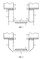
- FIG. 1 shows a first embodiment of the sensor according to the invention.
- the sensor comprises a cell element which consists of a membrane 1 and holders 3 and 7, which are made of ceramic material.
- the membrane 1 and the holder 3 and 7 are integrally formed.
- z. B. also the brackets 3 and 7 be designed as a ring.
- the brackets 3 and 7 are formed in the same and / or in a separate manufacturing process as the membrane 1.
- the brackets 3 and 7 may be depending on the manufacturing process of the same material as the membrane 1, but may also be formed of different materials.
- the membrane is preferably between 200 ⁇ m and 500 ⁇ m thick.
- the height of the brackets 3 and 7 between the points A and E is preferably 1.5 to 3 mm.
- the length of the arrangement between the points A and B is preferably 10 to 40 mm.
- the length of the membrane 1 between the points C and D is preferably 10 to 30 mm.
- the membrane is preferably made of a high temperature multilayer ceramic HTCC made. In this way, a monolithic production of the entire sensor cell can be made possible.
- the cell further comprises a metal layer 2 which, for example, is also produced in the sintering process for producing the ceramic. The production of the metal layer 2 can also or alternatively, for example, by plating or sputtering done.
- the thickness of the metal layer 2 is preferably 10 to 30 microns and is preferably made of metals that can survive the sintering process, such. B. molybdenum.
- the layer 2 may further be polished, and it forms an electrode of a condenser for measuring the pressure.
- the arrangement of the cell on the supports 3 and 7 may preferably be metallized with a Cu / Ag mixture.
- This metallization 4 can take on the role of a solder.
- a metallic object, such as, for example, the disk 5, can be attached to it, and these are hermetically connected, for example, by means of a soldering process. The dimensioning of the arrangement is chosen so that a tension-free as possible structure is created.
- the compounds E and F are hermetically sealed.
- the metallic article 5 As a material, for example Kovar.
- a material for example Kovar.
- portions 5 and 3 of the assembly at junctions E and F can be coated with other materials, such as metal, to provide a food grade sensor.
- the housing element 8 of the sensor can, for. B. by laser spot welding to the section or the disc 5 are welded.
- FIG. 2 shows a second embodiment of the sensor according to the invention, wherein compared to the first embodiment, the metallic layer 2, that is, the capacitor electrode 2, is arranged on the inside of the cell. Furthermore, edges of the cell, in particular the brackets 3 and 7 are bevelled.
- This arrangement may, for. B. used in the food industry. If, for example, a food stream is brought laterally onto the arrangement, high flow resistances arise due to the otherwise vertical facades, which can lead to high loads. The bevels reduce these loads. Thus, the entire assembly can be exposed to higher lateral pressures.
- the geometric dimensioning of the assembly can be chosen to be optimum for the industrial requirements of using these pressure sensors.
- the metallization layer 2 is formed within the assembly.
- the electrode 2 forms part of a capacitor for measuring the pressure.
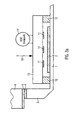
- FIG. 3a shows a detailed view of the second embodiment. It shows how counter electrodes 11 of the capacitor, which are arranged on a carrier element (carrier piece) 13, which may also be made of ceramic or HTCC material.
- the support piece 13 is connected to the membrane by means of a bonding compound, which is preferably made of glass or glass alloys.
- the carrier which is connected by means of spacers 12 made of a bonding alloy with the membrane 1, may for example be guided by means of an arrangement to allow a pressure 15 on the membrane to change the capacitance of the capacitor.
- the carrier 13 may also be incorporated by means of a precision mechanism, not shown here, be held and / or positioned. The positioning can be carried out by means of the signal of the capacitor and can be carried out very accurately.
- an electronics 14, for example, as an ASIC or as multiple ASICs may be provided.
- FIG. 3b illustrated modification of the embodiment according to Fig. 3B consists in that the support piece 13 comprises an adjusting and / or positioning (for example, has an external thread which is screwed into an internal thread of the brackets 3 and 7), in which case can be dispensed with the spacer elements 12.
- the positioning of the carrier element 13 can take place before or after the fluid-tight connection of the holders 3, 7, wherein in the latter case, if appropriate, the housing element also has an internal thread.
- FIG. 4 shows a third embodiment of the sensor according to the invention, wherein a front alignment of the cell / membrane is achieved with the housing by the cell is performed on a housing 8 of the sensor by attaching a weld 15, which connects the components 4 and 5 together.
- a hermetic seal is also achieved by means of welding.
- FIG. 5 shows a fourth embodiment of the pressure sensor according to the invention, which substantially corresponds to the third embodiment and only the membrane 1 of the cell element is flush-mounted with the housing element 8 of the cell element.
Abstract
Description
Die vorliegende Erfindung betrifft einen Sensor, insbesondere Drucksensor, für ein Fluid. Die Erfindung betrifft weiterhin ein Verfahren zur Herstellung eines Sensors, insbesondere eines Drucksensors, für ein Fluid.The present invention relates to a sensor, in particular a pressure sensor, for a fluid. The invention further relates to a method for producing a sensor, in particular a pressure sensor, for a fluid.
Drucksensoren zur Messung von Drücken in Fluiden, also von Gasen oder Flüssigkeiten sowie viskosen Lösungen und Materialien (wie z.B. Öl, Honig, Sirup, Kaffeesahne, Wurstmasse, Schokoladenmasse, Teig), sind in verschiedenen Ausführungen bekannt. Beispielsweise existieren kapazitive Drucksensoren, die einen Kondensator oder mehrere Kondensatoren enthalten. Bei Druckbeaufschlagung werden die Abstände einer Membran zu zwei beidseitig gegenüberliegenden Kondensatorplatten verändert, wodurch sich auch die Dehnkapazität der Kondensatoren verändert, was ein Maß für den Druck darstellt. Der oder die Kondensatoren können Teil eines Verstärkers sein dessen Ausgangssignal von der Kapazität abhängig ist.Pressure sensors for measuring pressures in fluids, such as gases or liquids, and viscous solutions and materials (such as oil, honey, syrup, creamer, sausage, chocolate mass, dough) are known in various designs. For example, there are capacitive pressure sensors that contain one or more capacitors. When pressurized, the distances of a membrane are changed to two opposite sides of the capacitor plates, which also changes the expansion capacity of the capacitors, which is a measure of the pressure. The one or more capacitors may be part of an amplifier whose output signal is dependent on the capacity.
Für hygienische Anwendungen z. B. im Pharmabereich, in der Lebensmittelindustrie oder in der Getränkeindustrie werden hohe Anforderungen an die Sterilität gesetzt. Weil die herkömmlichen Drucksensoren jedoch zur Abdichtung der Membranen oder der Druckzellen gummiartige oder allgemein elastische Dichtungen aufweisen, sind diese für solche Zwecke und Anwendungen nicht geeignet und deshalb nachteilig, weil sich beispielsweise Bakterien und Keime in derartigen Dichtungen einnisten können. Ferner sind fluidseitige Todräume des Sensors nachteilig, da sich auch darin Ablagerungen und insbesondere Keime ausbilden können.For hygienic applications z. As in the pharmaceutical industry, in the food industry or in the beverage industry high demands are placed on the sterility. However, because the conventional pressure sensors for sealing the membranes or the pressure cells have rubbery or generally elastic seals, they are not suitable for such purposes and applications and are disadvantageous because, for example, bacteria and germs can nest in such seals. Furthermore, fluid-side dead spaces of the sensor are disadvantageous since deposits and, in particular, germs can also be formed therein.
Der vorliegenden Erfindung liegt gegenüber dem Stand der Technik die Aufgabe zugrunde, einen Sensor, insbesondere einen Drucksensor zur Verfügung zu stellen, der die oben genannten Nachteile überwindet und beispielsweise für hygienische Anwendungen geeignet ist.The present invention is based on the object of the present invention to provide a sensor, in particular a pressure sensor, which overcomes the abovementioned disadvantages and is suitable, for example, for hygienic applications.
Die oben genannte Aufgabe wird durch einen Sensor, insbesondere einen Drucksensor gemäß Patentanspruch 1 gelöst.The above object is achieved by a sensor, in particular a pressure sensor according to
Der erfindungsgemäße Sensor für ein Fluid (insbesondere für Flüssigkeiten, Gase und viskose Fluide) weist ein Gehäuseelement, ein Zellenelement, deren Material vorzugsweise Keramik umfasst, und wenigstens eine Versiegelung zum fluiddichten Verbinden der Zelle mit dem Gehäuseelement des Sensors auf. Mit fluiddicht ist insbesondere flüssigkeitsdicht und/oder gasdicht und/oder dicht für das viskose Fluid gemeint bzw. allgemein hermetisch dicht. Durch die Verwendung einer Versiegelung wird das Zellenelement mit dem Sensorgehäuse fluiddicht verbunden, ohne dass eine elastische Dichtung, wie beispielsweise eine Gummidichtung, erforderlich ist. In einer beispielhaften Ausführung kann das Zellenelement Keramikmaterial umfasssen.The sensor according to the invention for a fluid (in particular for liquids, gases and viscous fluids) has a housing element, a cell element whose material preferably comprises ceramic, and at least one seal for fluid-tight connection of the cell to the housing element of the sensor. By fluid-tight is meant in particular liquid-tight and / or gas-tight and / or dense for the viscous fluid or generally hermetically sealed. By using a seal, the cell member is fluid-tightly connected to the sensor housing without the need for an elastic seal, such as a rubber seal. In an exemplary embodiment, the cell element may comprise ceramic material.
Eine Weiterbildung des erfindungsgemäßen Sensors besteht darin, dass das Zellenelement eine keramische Membran umfassen kann. Die Membran besteht somit aus einem für hygienische Zwecke geeigneten Material und die druckabhängige Wölbung dieser keramischen Membran kann ausgenutzt werden, um Drücke zu messen.A development of the sensor according to the invention is that the cell element may comprise a ceramic membrane. The membrane thus consists of a material suitable for hygienic purposes and the pressure-dependent curvature of this ceramic membrane can be utilized to measure pressures.
Gemäß einer anderen Weiterbildung kann das Zellenelement wenigstens eine Halterung zum Haltern der Membran umfassen, wobei die wenigstens eine Versiegelung die wenigstens eine Halterung mit dem Gehäuseelement des Sensors dicht verbindet. Mit einer solchen Halterung kann die Membran in einer gewünschten Position am Sensorgehäuseelement befestigt werden.According to another development, the cell element may comprise at least one holder for holding the membrane, wherein the at least one seal tightly connects the at least one holder to the housing element of the sensor. With such a holder, the membrane can be fixed in a desired position on the sensor housing element.
Eine andere Weiterbildung besteht darin, dass die wenigstens eine Halterung vorzugsweise aus dem gleichen Material und/oder einstückig mit der Membran ausgebildet sein kann. Auf diese Weise kann die Membran und die Halterung im gleichen Herstellungsprozess monolithisch erhalten werden.Another development is that the at least one holder can preferably be formed of the same material and / or integral with the membrane. In this way, the membrane and the holder can be obtained monolithically in the same manufacturing process.
Eine andere Weiterbildung besteht darin, dass eine Seite der Membran mit einer ersten Kondensatorelektrode versehen sein kann. Dies hat den Vorteil, dass die (keramische) Membran und die eine Kondensatorelektrode eine Einheit bilden, wodurch eine einfache Ausführung des Kondensators ermöglicht wird. Dabei kann diese eine Kondensatorelektrode als metallische Schicht auf einer der Seiten der Membran ausgebildet sein.Another development consists in that one side of the membrane can be provided with a first capacitor electrode. This has the advantage that the (ceramic) membrane and the one capacitor electrode form a unit, whereby a simple design of the capacitor is made possible. In this case, this one capacitor electrode may be formed as a metallic layer on one of the sides of the membrane.
Eine andere Weiterbildung des Sensors besteht darin, dass die wenigstens eine Versiegelung eine metallische Schicht, insbesondere Lot und/oder einen Keramikkleber und/oder einen durch UV-Licht härtbaren Kleber und/oder einen Glaskleber umfassen kann. Auf diese Weise werden fluiddichte Verbindungen zwischen der Zelle und dem Sensorgehäuse ohne die Verwendung von Gummidichtungen ermöglicht.Another development of the sensor is that the at least one seal may comprise a metallic layer, in particular solder and / or a ceramic adhesive and / or a UV-curable adhesive and / or a glass adhesive. In this way, fluid-tight connections between the cell and the sensor housing are made possible without the use of rubber seals.
Gemäß einer anderen Weiterbildung kann die Membran aus Hochtemperatur-Mehrlagenkeramik (HTCC) gefertigt sein. Dieses Material ist für die Verwendung als Sensormembran gut geeignet, da sich Mehrlagenschaltungen auf der Basis von gesinterten Keramikträgern mit Leiterbahnen erzeugen lassen.According to another embodiment, the membrane may be made of high temperature multilayer ceramic (HTCC). This material is well suited for use as a sensor membrane, since multilayer circuits based on sintered ceramic carriers can be produced with conductor tracks.
Eine andere Weiterbildung besteht darin, dass das Gehäuse einen Abschnitt zum Verbinden mit der Zelle aufweisen kann, deren Material Kovar umfasst. Da Kovar einen geringen Wärmeausdehnungskoeffizienten hat, der insbesondere geringer als der Wärmeausdehnungskoeffizienten typischer Metalle ist, können spannungsfreie Verbindungen zwischen der Membran bzw. der Halterung der Membran und dem Befestigungsabschnitt an dem Sensorgehäuse ausgeführt werden.Another development is that the housing may have a portion for connection to the cell, whose material comprises Kovar. Since Kovar has a low coefficient of thermal expansion, which in particular is less than the thermal expansion coefficient of typical metals, stress-free connections between the membrane or the holder of the membrane and the mounting portion can be performed on the sensor housing.
Gemäß einer anderen Weiterbildung des erfindungsgemäßen Sensors oder einer seiner Weiterbildungen, können die fluidseitigen Begrenzungen der Zelle abgerundet und/oder abgeschrägt sein, so dass beispielsweise ein Fluid-Strömungswiderstand der Zelle vermindert wird.According to another development of the sensor according to the invention or one of its developments, the fluid-side boundaries of the cell may be rounded and / or bevelled so that, for example, a fluid flow resistance of the cell is reduced.
Eine andere Weiterbildung besteht darin, dass eine zweite Kondensatorelektrode in einem fluidabgewandten Bereich der Zelle bzw. auf einer fluidabgewandten Seite der Membran angeordnet ist.Another development consists in that a second capacitor electrode is arranged in a fluid-remote region of the cell or on a fluid-remote side of the membrane.
Eine andere Weiterbildung besteht darin, dass die wenigstens eine zweite Kondensatorelektrode auf einem Trägerelement angeordnet ist. Auf diese Weise kann die zweite Kondensatorelektrode z.B. bezogen auf einen drucklosen Zustand des Sensors in einem vorbestimmten Abstand zur ersten Kondensatorelektrode angeordnet werden.Another development consists in that the at least one second capacitor electrode is arranged on a carrier element. In this way, the second capacitor electrode may be e.g. are arranged at a predetermined distance from the first capacitor electrode relative to a non-pressurized state of the sensor.
Gemäß einer anderen Weiterbildung des erfindungsgemäßen Sensors oder einer seiner Weiterbildungen ist das Zellenelement relativ zum Gehäuseelement frontbündig angeordnet. Auf diese Weise kann insbesondere die Membran mit der fluidseitigen Begrenzung des Gehäuseelements ausgerichtet sein, um z.B. den .Fluid-Strömungswiderstand zu vermindern.According to another embodiment of the sensor according to the invention or one of its refinements, the cell element is arranged flush with the housing element relative to the front. In this way, in particular, the diaphragm can be aligned with the fluid-side boundary of the housing element, in order, e.g. to reduce the fluid flow resistance.
Gemäß einer anderen Weiterbildung des erfindungsgemäßen Sensors oder einer seiner Weiterbildungen kann das Gehäuseelement eine Befestigungsvorrichtung aufweisen, mit der es an ein weiteres Gehäuseelement befestigt werden kann, z.B. ein Gewinde, welches in ein weiteres Gewinde des weiteren Gehäuseelements schraubbar ist.According to another embodiment of the sensor according to the invention or one of its developments, the housing element may have a fastening device with which it can be fastened to a further housing element, e.g. a thread which can be screwed into a further thread of the further housing element.
Gemäß eine anderen Weiterbildung kann das Trägerelement ein Außengewinde aufweisen, welches in ein Gewinde des Gehäuseelements und/oder des Zellenelements einschraubbar ist und/oder wobei Abstandselemente zwischen dem Trägerelement und der Membran vorgesehen sind.According to another development, the carrier element may have an external thread which can be screwed into a thread of the housing element and / or the cell element and / or wherein spacer elements are provided between the carrier element and the membrane.
Die oben genannte Aufgabe wird weiterhin durch ein Verfahren zur Herstellung eines Sensors, insbesondere eines Drucksensors, für ein Fluid, nach Patentanspruch 12 gelöst. Das Verfahren umfasst die folgenden Schritte: Sintern eines keramischen Zellenelements mit einer Membran; und fluiddichtes Versiegeln des Zellenelements mit einem Gehäuseelement des Sensors.The above object is further achieved by a method for producing a sensor, in particular a pressure sensor, for a fluid, according to claim 12 solved. The method comprises the following steps: sintering a ceramic cell element with a membrane; and fluid-tightly sealing the cell element with a housing element of the sensor.
In einer Weiterbildung des Verfahrens kann die Membran auf einer Seite mit einer metallischen Schicht zur Ausbildung einer Elektrode gesintert und/oder metallisiert werden.In one development of the method, the membrane can be sintered on one side with a metallic layer to form an electrode and / or metallized.
Gemäß einer anderen Weiterbildung kann das Verfahren den weiteren Schritt umfassen: Positionieren eines Trägerelements mit wenigstens einer Gegenelektrode relativ zur Membran, wobei das Positionieren vorzugsweise durch Einschrauben des Trägerelements in wenigstens eine Halterung oder durch Vorsehen von Abstandselementen zwischen dem Trägerelement und der Membran erfolgt.According to another development, the method may comprise the further step of positioning a carrier element with at least one counterelectrode relative to the membrane, the positioning preferably taking place by screwing the carrier element into at least one holder or by providing spacer elements between the carrier element and the membrane.
Gemäß einer anderen Weiterbildung kann das Verfahren den weiteren Schritt umfassen: Anordnen des Zellenelements so, dass eine fluidseitige Begrenzung des Zellenelements frontbündig mit dem Gehäuseelement istAccording to another development, the method may include the further step of arranging the cell element such that a fluid-side boundary of the cell element is flush with the housing element
In einer anderen Weiterbildung kann das Versiegeln mittels Schweißen und/der Löten und/oder Kleben, erfolgen, wobei das Versiegeln insbesondere ohne Anbringen einer Gummidichtung erfolgt.In another development, the sealing can be carried out by means of welding and / or soldering and / or gluing, the sealing taking place, in particular, without the application of a rubber seal.
Weitere Merkmale und Vorteile der vorliegenden Erfindung werden im Weiteren mit Bezug auf die Figuren beschrieben, die lediglich beispielhafte Ausführungsformen veranschaulichen und durchaus nicht den gesamten Umfang der Erfindung darstellen. Es versteht sich, dass die gezeigten Merkmale in anderen Kombinationen, als in den Beispielen beschrieben, im Rahmen der Erfindung Verwendung finden können.Other features and advantages of the present invention will be further described with reference to the figures which illustrate only exemplary embodiments and which by no means represent the full scope of the invention. It is understood that the features shown in other combinations than described in the examples can be used within the scope of the invention.
-
Fig. 1 zeigt eine erste Ausführungsform des erfindungsgemäßen Sensors.Fig. 1 shows a first embodiment of the sensor according to the invention. -
Fig. 2 zeigt eine zweite Ausführungsform des erfindungsgemäßen Sensors.Fig. 2 shows a second embodiment of the sensor according to the invention. -
Fig. 3a zeigt eine Detaildarstellung der zweiten Ausführungsform des erfindungsgemäßen Sensors.Fig. 3a shows a detailed view of the second embodiment of the sensor according to the invention. -
Fig. 3b zeigt eine Modifikation des Sensors gemäßFig. 3a .Fig. 3b shows a modification of the sensor according toFig. 3a , -
Fig. 4 zeigt eine dritte Ausführungsform des erfindungsgemäßen Sensors.Fig. 4 shows a third embodiment of the sensor according to the invention. -
Fig. 5 zeigt eine vierte Ausführungsform des erfindungsgemäßen Sensors.Fig. 5 shows a fourth embodiment of the sensor according to the invention.
Die Membran ist vorzugsweise zwischen 200 µm und 500 µm dick. Die Höhe der Halterungen 3 und 7 zwischen den Punkten A und E beträgt vorzugsweise 1,5 bis 3 mm. Die Länge der Anordnung zwischen den Punkten A und B beträgt vorzugsweise 10 bis 40 mm. Die Länge der Membran 1 zwischen den Punkten C und D beträgt vorzugsweise 10 bis 30 mm. Die Membran ist vorzugsweise aus einer Hochtemperatur-Mehrlagenkeramik HTCC gefertigt. Auf diese Weise kann eine monolithische Herstellung der gesamten Sensorzelle ermöglicht werden. Die Zelle weist ferner eine Metallschicht 2 auf, welche beispielsweise ebenfalls in dem Sinterprozess zur Herstellung der Keramik hergestellt wird. Die Herstellung der Metallschicht 2 kann ferner oder alternativ beispielsweise auch durch Galvanisieren oder Sputtern erfolgen. Die Dicke der Metallschicht 2 beträgt vorzugsweise 10 bis 30 µm und ist vorzugsweise aus Metallen, welche den Sinterungsprozess überstehen können, wie z. B. Molybdän. Die Schicht 2 kann weiterhin poliert werden, und sie bildet eine Elektrode eines Kondensators zur Messung des Drucks. Ferner kann die Anordnung der Zelle an den Halterungen 3 und 7 vorzugsweise mit einer Cu/Ag-Mischung metallisiert werden. Diese Metallisierung 4 kann die Rolle eines Lots übernehmen. Daran kann ein metallischer Gegenstand wie beispielsweise die Scheibe 5 angebracht werden, wobei diese beispielsweise mittels eines Lötverfahrens hermetisch verbunden werden. Die Dimensionierung der Anordnung ist so gewählt, dass eine möglichst spannungsfreie Struktur entsteht. Die Verbindungen E und F sind hermetisch dicht.The membrane is preferably between 200 μm and 500 μm thick. The height of the
Um eine spannungsfreie Anordnung, und/oder beispielsweise eine gut haftende Versiegelung zu ermöglichen, wählt man für den metallischen Gegenstand 5 als Material beispielsweise Kovar aus. Jedoch ist auch eine andere Materialkombination denkbar, welche den Zweck der Spannungsfreiheit erfüllt. Ferner können Abschnitte 5 und 3 der Anordnung an den Verbindungspunkten E und F mit weiteren Materialien, wie Metall beschichtet werden, um einen für Lebensmittel tauglichen Sensor zu schaffen. Das Gehäuseelement 8 des Sensors kann z. B. mittels Laserpunktschweißen an den Abschnitt bzw. die Scheibe 5 geschweißt werden.In order to allow a tension-free arrangement, and / or, for example, a good adhesive seal, one selects for the
Eine in
>>
Die hier beschriebenen Ausführungsformen stellen lediglich Beispiele der Erfindung dar, die in den nachfolgenden Patentansprüchen definiert ist.The embodiments described herein are merely examples of the invention defined in the following claims.
Claims (15)
Priority Applications (1)
| Application Number | Priority Date | Filing Date | Title |
|---|---|---|---|
| EP10014707A EP2455737A1 (en) | 2010-11-17 | 2010-11-17 | Sensor with ceramic cell |
Applications Claiming Priority (1)
| Application Number | Priority Date | Filing Date | Title |
|---|---|---|---|
| EP10014707A EP2455737A1 (en) | 2010-11-17 | 2010-11-17 | Sensor with ceramic cell |
Publications (1)
| Publication Number | Publication Date |
|---|---|
| EP2455737A1 true EP2455737A1 (en) | 2012-05-23 |
Family
ID=43617027
Family Applications (1)
| Application Number | Title | Priority Date | Filing Date |
|---|---|---|---|
| EP10014707A Withdrawn EP2455737A1 (en) | 2010-11-17 | 2010-11-17 | Sensor with ceramic cell |
Country Status (1)
| Country | Link |
|---|---|
| EP (1) | EP2455737A1 (en) |
Cited By (1)
| Publication number | Priority date | Publication date | Assignee | Title |
|---|---|---|---|---|
| WO2016015758A1 (en) * | 2014-07-30 | 2016-02-04 | Vega Grieshaber Kg | Process connection |
Citations (3)
| Publication number | Priority date | Publication date | Assignee | Title |
|---|---|---|---|---|
| US4898035A (en) * | 1988-01-16 | 1990-02-06 | Ngk Insulators, Ltd. | Pressure sensor having sealing member for sealing housing interior with respect to external space |
| US20060191351A1 (en) * | 2005-02-25 | 2006-08-31 | Meehan Peter G | Sealed capacitive sensor |
| DE102007030910A1 (en) * | 2007-07-03 | 2009-01-08 | Endress + Hauser Gmbh + Co. Kg | pressure sensor |
-
2010
- 2010-11-17 EP EP10014707A patent/EP2455737A1/en not_active Withdrawn
Patent Citations (3)
| Publication number | Priority date | Publication date | Assignee | Title |
|---|---|---|---|---|
| US4898035A (en) * | 1988-01-16 | 1990-02-06 | Ngk Insulators, Ltd. | Pressure sensor having sealing member for sealing housing interior with respect to external space |
| US20060191351A1 (en) * | 2005-02-25 | 2006-08-31 | Meehan Peter G | Sealed capacitive sensor |
| DE102007030910A1 (en) * | 2007-07-03 | 2009-01-08 | Endress + Hauser Gmbh + Co. Kg | pressure sensor |
Cited By (1)
| Publication number | Priority date | Publication date | Assignee | Title |
|---|---|---|---|---|
| WO2016015758A1 (en) * | 2014-07-30 | 2016-02-04 | Vega Grieshaber Kg | Process connection |
Similar Documents
| Publication | Publication Date | Title |
|---|---|---|
| DE60031869T2 (en) | CAPACITIVE DRUCKWANDLER | |
| DE3003449C2 (en) | Pressure sensor | |
| EP0735353B1 (en) | Pressure sensor | |
| EP2516966B1 (en) | Sensor wherein the sensing element is part of the housing | |
| EP0759547A1 (en) | Pressure sensor | |
| EP1167938B1 (en) | Pressure measuring device | |
| EP0757237A2 (en) | Pressure transducer | |
| DE3122438A1 (en) | PRESSURE SOCKET | |
| DE4011734A1 (en) | CAPACITIVE DIFFERENTIAL PRESSURE DETECTOR | |
| EP0995979B1 (en) | Pressure sensor | |
| EP1039284A1 (en) | Capacitive sensor of pressure or differential pressure | |
| DE10221219B4 (en) | pressure sensor | |
| EP2294376B1 (en) | Pressure sensor assembly | |
| DE102014119111A1 (en) | Pressure measuring cell | |
| DE102014104506A1 (en) | pressure sensor | |
| EP2455737A1 (en) | Sensor with ceramic cell | |
| DE102015116147A1 (en) | Sensor assembly for a sensor, sensor and thus formed measuring system | |
| DE102007058132A1 (en) | Measuring system, in particular for flow measurement of a flowing in a pipeline medium | |
| DE102004023063A1 (en) | Micromechanical piezoresistive pressure sensor device | |
| DE102011017462A1 (en) | Device for measuring difference between pressures of measuring elements arranged on measuring chip, has electrodes that are deflected based on results of pressures and independent to common electrode | |
| EP2589945B1 (en) | Device for detecting a pressure of a fluid medium | |
| DE102010051644B4 (en) | Pressure sensor with ceramic cell | |
| DE102013114741A1 (en) | pressure sensor | |
| DE10042734C1 (en) | Multi-purpose pressure sensor has annular adhesive surface for securing pressure sensor hybrid component group within sensor housing | |
| EP3175209B1 (en) | Process connection |
Legal Events
| Date | Code | Title | Description |
|---|---|---|---|
| PUAI | Public reference made under article 153(3) epc to a published international application that has entered the european phase |
Free format text: ORIGINAL CODE: 0009012 |
|
| 17P | Request for examination filed |
Effective date: 20101117 |
|
| AK | Designated contracting states |
Kind code of ref document: A1 Designated state(s): AL AT BE BG CH CY CZ DE DK EE ES FI FR GB GR HR HU IE IS IT LI LT LU LV MC MK MT NL NO PL PT RO RS SE SI SK SM TR |
|
| AX | Request for extension of the european patent |
Extension state: BA ME |
|
| STAA | Information on the status of an ep patent application or granted ep patent |
Free format text: STATUS: THE APPLICATION HAS BEEN WITHDRAWN |
|
| 18W | Application withdrawn |
Effective date: 20121122 |