EP2463149A1 - Headlamp control to prevent glare - Google Patents
Headlamp control to prevent glare Download PDFInfo
- Publication number
- EP2463149A1 EP2463149A1 EP12001596A EP12001596A EP2463149A1 EP 2463149 A1 EP2463149 A1 EP 2463149A1 EP 12001596 A EP12001596 A EP 12001596A EP 12001596 A EP12001596 A EP 12001596A EP 2463149 A1 EP2463149 A1 EP 2463149A1
- Authority
- EP
- European Patent Office
- Prior art keywords
- vehicle
- light
- control unit
- exterior
- headlamp
- Prior art date
- Legal status (The legal status is an assumption and is not a legal conclusion. Google has not performed a legal analysis and makes no representation as to the accuracy of the status listed.)
- Granted
Links
Images


Classifications
-
- B—PERFORMING OPERATIONS; TRANSPORTING
- B60—VEHICLES IN GENERAL
- B60Q—ARRANGEMENT OF SIGNALLING OR LIGHTING DEVICES, THE MOUNTING OR SUPPORTING THEREOF OR CIRCUITS THEREFOR, FOR VEHICLES IN GENERAL
- B60Q1/00—Arrangement of optical signalling or lighting devices, the mounting or supporting thereof or circuits therefor
- B60Q1/02—Arrangement of optical signalling or lighting devices, the mounting or supporting thereof or circuits therefor the devices being primarily intended to illuminate the way ahead or to illuminate other areas of way or environments
- B60Q1/04—Arrangement of optical signalling or lighting devices, the mounting or supporting thereof or circuits therefor the devices being primarily intended to illuminate the way ahead or to illuminate other areas of way or environments the devices being headlights
- B60Q1/06—Arrangement of optical signalling or lighting devices, the mounting or supporting thereof or circuits therefor the devices being primarily intended to illuminate the way ahead or to illuminate other areas of way or environments the devices being headlights adjustable, e.g. remotely-controlled from inside vehicle
- B60Q1/08—Arrangement of optical signalling or lighting devices, the mounting or supporting thereof or circuits therefor the devices being primarily intended to illuminate the way ahead or to illuminate other areas of way or environments the devices being headlights adjustable, e.g. remotely-controlled from inside vehicle automatically
- B60Q1/085—Arrangement of optical signalling or lighting devices, the mounting or supporting thereof or circuits therefor the devices being primarily intended to illuminate the way ahead or to illuminate other areas of way or environments the devices being headlights adjustable, e.g. remotely-controlled from inside vehicle automatically due to special conditions, e.g. adverse weather, type of road, badly illuminated road signs or potential dangers
-
- B—PERFORMING OPERATIONS; TRANSPORTING
- B60—VEHICLES IN GENERAL
- B60Q—ARRANGEMENT OF SIGNALLING OR LIGHTING DEVICES, THE MOUNTING OR SUPPORTING THEREOF OR CIRCUITS THEREFOR, FOR VEHICLES IN GENERAL
- B60Q1/00—Arrangement of optical signalling or lighting devices, the mounting or supporting thereof or circuits therefor
- B60Q1/02—Arrangement of optical signalling or lighting devices, the mounting or supporting thereof or circuits therefor the devices being primarily intended to illuminate the way ahead or to illuminate other areas of way or environments
- B60Q1/04—Arrangement of optical signalling or lighting devices, the mounting or supporting thereof or circuits therefor the devices being primarily intended to illuminate the way ahead or to illuminate other areas of way or environments the devices being headlights
- B60Q1/06—Arrangement of optical signalling or lighting devices, the mounting or supporting thereof or circuits therefor the devices being primarily intended to illuminate the way ahead or to illuminate other areas of way or environments the devices being headlights adjustable, e.g. remotely-controlled from inside vehicle
- B60Q1/08—Arrangement of optical signalling or lighting devices, the mounting or supporting thereof or circuits therefor the devices being primarily intended to illuminate the way ahead or to illuminate other areas of way or environments the devices being headlights adjustable, e.g. remotely-controlled from inside vehicle automatically
- B60Q1/10—Arrangement of optical signalling or lighting devices, the mounting or supporting thereof or circuits therefor the devices being primarily intended to illuminate the way ahead or to illuminate other areas of way or environments the devices being headlights adjustable, e.g. remotely-controlled from inside vehicle automatically due to vehicle inclination, e.g. due to load distribution
-
- B—PERFORMING OPERATIONS; TRANSPORTING
- B60—VEHICLES IN GENERAL
- B60Q—ARRANGEMENT OF SIGNALLING OR LIGHTING DEVICES, THE MOUNTING OR SUPPORTING THEREOF OR CIRCUITS THEREFOR, FOR VEHICLES IN GENERAL
- B60Q1/00—Arrangement of optical signalling or lighting devices, the mounting or supporting thereof or circuits therefor
- B60Q1/02—Arrangement of optical signalling or lighting devices, the mounting or supporting thereof or circuits therefor the devices being primarily intended to illuminate the way ahead or to illuminate other areas of way or environments
- B60Q1/04—Arrangement of optical signalling or lighting devices, the mounting or supporting thereof or circuits therefor the devices being primarily intended to illuminate the way ahead or to illuminate other areas of way or environments the devices being headlights
- B60Q1/18—Arrangement of optical signalling or lighting devices, the mounting or supporting thereof or circuits therefor the devices being primarily intended to illuminate the way ahead or to illuminate other areas of way or environments the devices being headlights being additional front lights
-
- F—MECHANICAL ENGINEERING; LIGHTING; HEATING; WEAPONS; BLASTING
- F21—LIGHTING
- F21S—NON-PORTABLE LIGHTING DEVICES; SYSTEMS THEREOF; VEHICLE LIGHTING DEVICES SPECIALLY ADAPTED FOR VEHICLE EXTERIORS
- F21S41/00—Illuminating devices specially adapted for vehicle exteriors, e.g. headlamps
- F21S41/10—Illuminating devices specially adapted for vehicle exteriors, e.g. headlamps characterised by the light source
- F21S41/14—Illuminating devices specially adapted for vehicle exteriors, e.g. headlamps characterised by the light source characterised by the type of light source
- F21S41/141—Light emitting diodes [LED]
- F21S41/147—Light emitting diodes [LED] the main emission direction of the LED being angled to the optical axis of the illuminating device
- F21S41/148—Light emitting diodes [LED] the main emission direction of the LED being angled to the optical axis of the illuminating device the main emission direction of the LED being perpendicular to the optical axis
-
- F—MECHANICAL ENGINEERING; LIGHTING; HEATING; WEAPONS; BLASTING
- F21—LIGHTING
- F21S—NON-PORTABLE LIGHTING DEVICES; SYSTEMS THEREOF; VEHICLE LIGHTING DEVICES SPECIALLY ADAPTED FOR VEHICLE EXTERIORS
- F21S41/00—Illuminating devices specially adapted for vehicle exteriors, e.g. headlamps
- F21S41/10—Illuminating devices specially adapted for vehicle exteriors, e.g. headlamps characterised by the light source
- F21S41/14—Illuminating devices specially adapted for vehicle exteriors, e.g. headlamps characterised by the light source characterised by the type of light source
- F21S41/141—Light emitting diodes [LED]
- F21S41/151—Light emitting diodes [LED] arranged in one or more lines
- F21S41/153—Light emitting diodes [LED] arranged in one or more lines arranged in a matrix
-
- F—MECHANICAL ENGINEERING; LIGHTING; HEATING; WEAPONS; BLASTING
- F21—LIGHTING
- F21S—NON-PORTABLE LIGHTING DEVICES; SYSTEMS THEREOF; VEHICLE LIGHTING DEVICES SPECIALLY ADAPTED FOR VEHICLE EXTERIORS
- F21S41/00—Illuminating devices specially adapted for vehicle exteriors, e.g. headlamps
- F21S41/10—Illuminating devices specially adapted for vehicle exteriors, e.g. headlamps characterised by the light source
- F21S41/14—Illuminating devices specially adapted for vehicle exteriors, e.g. headlamps characterised by the light source characterised by the type of light source
- F21S41/162—Incandescent light sources, e.g. filament or halogen lamps
-
- F—MECHANICAL ENGINEERING; LIGHTING; HEATING; WEAPONS; BLASTING
- F21—LIGHTING
- F21S—NON-PORTABLE LIGHTING DEVICES; SYSTEMS THEREOF; VEHICLE LIGHTING DEVICES SPECIALLY ADAPTED FOR VEHICLE EXTERIORS
- F21S41/00—Illuminating devices specially adapted for vehicle exteriors, e.g. headlamps
- F21S41/20—Illuminating devices specially adapted for vehicle exteriors, e.g. headlamps characterised by refractors, transparent cover plates, light guides or filters
- F21S41/25—Projection lenses
-
- F—MECHANICAL ENGINEERING; LIGHTING; HEATING; WEAPONS; BLASTING
- F21—LIGHTING
- F21S—NON-PORTABLE LIGHTING DEVICES; SYSTEMS THEREOF; VEHICLE LIGHTING DEVICES SPECIALLY ADAPTED FOR VEHICLE EXTERIORS
- F21S41/00—Illuminating devices specially adapted for vehicle exteriors, e.g. headlamps
- F21S41/20—Illuminating devices specially adapted for vehicle exteriors, e.g. headlamps characterised by refractors, transparent cover plates, light guides or filters
- F21S41/285—Refractors, transparent cover plates, light guides or filters not provided in groups F21S41/24-F21S41/28
-
- F—MECHANICAL ENGINEERING; LIGHTING; HEATING; WEAPONS; BLASTING
- F21—LIGHTING
- F21S—NON-PORTABLE LIGHTING DEVICES; SYSTEMS THEREOF; VEHICLE LIGHTING DEVICES SPECIALLY ADAPTED FOR VEHICLE EXTERIORS
- F21S41/00—Illuminating devices specially adapted for vehicle exteriors, e.g. headlamps
- F21S41/30—Illuminating devices specially adapted for vehicle exteriors, e.g. headlamps characterised by reflectors
- F21S41/32—Optical layout thereof
- F21S41/321—Optical layout thereof the reflector being a surface of revolution or a planar surface, e.g. truncated
-
- F—MECHANICAL ENGINEERING; LIGHTING; HEATING; WEAPONS; BLASTING
- F21—LIGHTING
- F21S—NON-PORTABLE LIGHTING DEVICES; SYSTEMS THEREOF; VEHICLE LIGHTING DEVICES SPECIALLY ADAPTED FOR VEHICLE EXTERIORS
- F21S41/00—Illuminating devices specially adapted for vehicle exteriors, e.g. headlamps
- F21S41/40—Illuminating devices specially adapted for vehicle exteriors, e.g. headlamps characterised by screens, non-reflecting members, light-shielding members or fixed shades
- F21S41/47—Attachment thereof
-
- F—MECHANICAL ENGINEERING; LIGHTING; HEATING; WEAPONS; BLASTING
- F21—LIGHTING
- F21S—NON-PORTABLE LIGHTING DEVICES; SYSTEMS THEREOF; VEHICLE LIGHTING DEVICES SPECIALLY ADAPTED FOR VEHICLE EXTERIORS
- F21S41/00—Illuminating devices specially adapted for vehicle exteriors, e.g. headlamps
- F21S41/60—Illuminating devices specially adapted for vehicle exteriors, e.g. headlamps characterised by a variable light distribution
- F21S41/62—Illuminating devices specially adapted for vehicle exteriors, e.g. headlamps characterised by a variable light distribution for adaptation between right-hand and left-hand traffic
-
- F—MECHANICAL ENGINEERING; LIGHTING; HEATING; WEAPONS; BLASTING
- F21—LIGHTING
- F21S—NON-PORTABLE LIGHTING DEVICES; SYSTEMS THEREOF; VEHICLE LIGHTING DEVICES SPECIALLY ADAPTED FOR VEHICLE EXTERIORS
- F21S41/00—Illuminating devices specially adapted for vehicle exteriors, e.g. headlamps
- F21S41/60—Illuminating devices specially adapted for vehicle exteriors, e.g. headlamps characterised by a variable light distribution
- F21S41/63—Illuminating devices specially adapted for vehicle exteriors, e.g. headlamps characterised by a variable light distribution by acting on refractors, filters or transparent cover plates
- F21S41/64—Illuminating devices specially adapted for vehicle exteriors, e.g. headlamps characterised by a variable light distribution by acting on refractors, filters or transparent cover plates by changing their light transmissivity, e.g. by liquid crystal or electrochromic devices
- F21S41/645—Illuminating devices specially adapted for vehicle exteriors, e.g. headlamps characterised by a variable light distribution by acting on refractors, filters or transparent cover plates by changing their light transmissivity, e.g. by liquid crystal or electrochromic devices by electro-optic means, e.g. liquid crystal or electrochromic devices
-
- F—MECHANICAL ENGINEERING; LIGHTING; HEATING; WEAPONS; BLASTING
- F21—LIGHTING
- F21S—NON-PORTABLE LIGHTING DEVICES; SYSTEMS THEREOF; VEHICLE LIGHTING DEVICES SPECIALLY ADAPTED FOR VEHICLE EXTERIORS
- F21S41/00—Illuminating devices specially adapted for vehicle exteriors, e.g. headlamps
- F21S41/60—Illuminating devices specially adapted for vehicle exteriors, e.g. headlamps characterised by a variable light distribution
- F21S41/67—Illuminating devices specially adapted for vehicle exteriors, e.g. headlamps characterised by a variable light distribution by acting on reflectors
- F21S41/675—Illuminating devices specially adapted for vehicle exteriors, e.g. headlamps characterised by a variable light distribution by acting on reflectors by moving reflectors
-
- F—MECHANICAL ENGINEERING; LIGHTING; HEATING; WEAPONS; BLASTING
- F21—LIGHTING
- F21S—NON-PORTABLE LIGHTING DEVICES; SYSTEMS THEREOF; VEHICLE LIGHTING DEVICES SPECIALLY ADAPTED FOR VEHICLE EXTERIORS
- F21S41/00—Illuminating devices specially adapted for vehicle exteriors, e.g. headlamps
- F21S41/60—Illuminating devices specially adapted for vehicle exteriors, e.g. headlamps characterised by a variable light distribution
- F21S41/68—Illuminating devices specially adapted for vehicle exteriors, e.g. headlamps characterised by a variable light distribution by acting on screens
- F21S41/683—Illuminating devices specially adapted for vehicle exteriors, e.g. headlamps characterised by a variable light distribution by acting on screens by moving screens
- F21S41/686—Blades, i.e. screens moving in a vertical plane
-
- F—MECHANICAL ENGINEERING; LIGHTING; HEATING; WEAPONS; BLASTING
- F21—LIGHTING
- F21S—NON-PORTABLE LIGHTING DEVICES; SYSTEMS THEREOF; VEHICLE LIGHTING DEVICES SPECIALLY ADAPTED FOR VEHICLE EXTERIORS
- F21S41/00—Illuminating devices specially adapted for vehicle exteriors, e.g. headlamps
- F21S41/60—Illuminating devices specially adapted for vehicle exteriors, e.g. headlamps characterised by a variable light distribution
- F21S41/68—Illuminating devices specially adapted for vehicle exteriors, e.g. headlamps characterised by a variable light distribution by acting on screens
- F21S41/683—Illuminating devices specially adapted for vehicle exteriors, e.g. headlamps characterised by a variable light distribution by acting on screens by moving screens
- F21S41/692—Shields, i.e. screens not creating an image meant to be projected
-
- F—MECHANICAL ENGINEERING; LIGHTING; HEATING; WEAPONS; BLASTING
- F21—LIGHTING
- F21S—NON-PORTABLE LIGHTING DEVICES; SYSTEMS THEREOF; VEHICLE LIGHTING DEVICES SPECIALLY ADAPTED FOR VEHICLE EXTERIORS
- F21S41/00—Illuminating devices specially adapted for vehicle exteriors, e.g. headlamps
- F21S41/60—Illuminating devices specially adapted for vehicle exteriors, e.g. headlamps characterised by a variable light distribution
- F21S41/68—Illuminating devices specially adapted for vehicle exteriors, e.g. headlamps characterised by a variable light distribution by acting on screens
- F21S41/683—Illuminating devices specially adapted for vehicle exteriors, e.g. headlamps characterised by a variable light distribution by acting on screens by moving screens
- F21S41/698—Shaft-shaped screens rotating along its longitudinal axis
-
- F—MECHANICAL ENGINEERING; LIGHTING; HEATING; WEAPONS; BLASTING
- F21—LIGHTING
- F21V—FUNCTIONAL FEATURES OR DETAILS OF LIGHTING DEVICES OR SYSTEMS THEREOF; STRUCTURAL COMBINATIONS OF LIGHTING DEVICES WITH OTHER ARTICLES, NOT OTHERWISE PROVIDED FOR
- F21V14/00—Controlling the distribution of the light emitted by adjustment of elements
-
- F—MECHANICAL ENGINEERING; LIGHTING; HEATING; WEAPONS; BLASTING
- F21—LIGHTING
- F21V—FUNCTIONAL FEATURES OR DETAILS OF LIGHTING DEVICES OR SYSTEMS THEREOF; STRUCTURAL COMBINATIONS OF LIGHTING DEVICES WITH OTHER ARTICLES, NOT OTHERWISE PROVIDED FOR
- F21V9/00—Elements for modifying spectral properties, polarisation or intensity of the light emitted, e.g. filters
- F21V9/40—Elements for modifying spectral properties, polarisation or intensity of the light emitted, e.g. filters with provision for controlling spectral properties, e.g. colour, or intensity
-
- B—PERFORMING OPERATIONS; TRANSPORTING
- B60—VEHICLES IN GENERAL
- B60Q—ARRANGEMENT OF SIGNALLING OR LIGHTING DEVICES, THE MOUNTING OR SUPPORTING THEREOF OR CIRCUITS THEREFOR, FOR VEHICLES IN GENERAL
- B60Q2300/00—Indexing codes for automatically adjustable headlamps or automatically dimmable headlamps
- B60Q2300/05—Special features for controlling or switching of the light beam
- B60Q2300/054—Variable non-standard intensity, i.e. emission of various beam intensities different from standard intensities, e.g. continuous or stepped transitions of intensity
-
- B—PERFORMING OPERATIONS; TRANSPORTING
- B60—VEHICLES IN GENERAL
- B60Q—ARRANGEMENT OF SIGNALLING OR LIGHTING DEVICES, THE MOUNTING OR SUPPORTING THEREOF OR CIRCUITS THEREFOR, FOR VEHICLES IN GENERAL
- B60Q2300/00—Indexing codes for automatically adjustable headlamps or automatically dimmable headlamps
- B60Q2300/05—Special features for controlling or switching of the light beam
- B60Q2300/056—Special anti-blinding beams, e.g. a standard beam is chopped or moved in order not to blind
-
- B—PERFORMING OPERATIONS; TRANSPORTING
- B60—VEHICLES IN GENERAL
- B60Q—ARRANGEMENT OF SIGNALLING OR LIGHTING DEVICES, THE MOUNTING OR SUPPORTING THEREOF OR CIRCUITS THEREFOR, FOR VEHICLES IN GENERAL
- B60Q2300/00—Indexing codes for automatically adjustable headlamps or automatically dimmable headlamps
- B60Q2300/10—Indexing codes relating to particular vehicle conditions
- B60Q2300/11—Linear movements of the vehicle
- B60Q2300/112—Vehicle speed
-
- B—PERFORMING OPERATIONS; TRANSPORTING
- B60—VEHICLES IN GENERAL
- B60Q—ARRANGEMENT OF SIGNALLING OR LIGHTING DEVICES, THE MOUNTING OR SUPPORTING THEREOF OR CIRCUITS THEREFOR, FOR VEHICLES IN GENERAL
- B60Q2300/00—Indexing codes for automatically adjustable headlamps or automatically dimmable headlamps
- B60Q2300/10—Indexing codes relating to particular vehicle conditions
- B60Q2300/11—Linear movements of the vehicle
- B60Q2300/114—Vehicle acceleration or deceleration
-
- B—PERFORMING OPERATIONS; TRANSPORTING
- B60—VEHICLES IN GENERAL
- B60Q—ARRANGEMENT OF SIGNALLING OR LIGHTING DEVICES, THE MOUNTING OR SUPPORTING THEREOF OR CIRCUITS THEREFOR, FOR VEHICLES IN GENERAL
- B60Q2300/00—Indexing codes for automatically adjustable headlamps or automatically dimmable headlamps
- B60Q2300/10—Indexing codes relating to particular vehicle conditions
- B60Q2300/12—Steering parameters
- B60Q2300/122—Steering angle
-
- B—PERFORMING OPERATIONS; TRANSPORTING
- B60—VEHICLES IN GENERAL
- B60Q—ARRANGEMENT OF SIGNALLING OR LIGHTING DEVICES, THE MOUNTING OR SUPPORTING THEREOF OR CIRCUITS THEREFOR, FOR VEHICLES IN GENERAL
- B60Q2300/00—Indexing codes for automatically adjustable headlamps or automatically dimmable headlamps
- B60Q2300/10—Indexing codes relating to particular vehicle conditions
- B60Q2300/13—Attitude of the vehicle body
- B60Q2300/132—Pitch
-
- B—PERFORMING OPERATIONS; TRANSPORTING
- B60—VEHICLES IN GENERAL
- B60Q—ARRANGEMENT OF SIGNALLING OR LIGHTING DEVICES, THE MOUNTING OR SUPPORTING THEREOF OR CIRCUITS THEREFOR, FOR VEHICLES IN GENERAL
- B60Q2300/00—Indexing codes for automatically adjustable headlamps or automatically dimmable headlamps
- B60Q2300/20—Indexing codes relating to the driver or the passengers
- B60Q2300/21—Manual control
-
- B—PERFORMING OPERATIONS; TRANSPORTING
- B60—VEHICLES IN GENERAL
- B60Q—ARRANGEMENT OF SIGNALLING OR LIGHTING DEVICES, THE MOUNTING OR SUPPORTING THEREOF OR CIRCUITS THEREFOR, FOR VEHICLES IN GENERAL
- B60Q2300/00—Indexing codes for automatically adjustable headlamps or automatically dimmable headlamps
- B60Q2300/30—Indexing codes relating to the vehicle environment
- B60Q2300/31—Atmospheric conditions
- B60Q2300/312—Adverse weather
-
- B—PERFORMING OPERATIONS; TRANSPORTING
- B60—VEHICLES IN GENERAL
- B60Q—ARRANGEMENT OF SIGNALLING OR LIGHTING DEVICES, THE MOUNTING OR SUPPORTING THEREOF OR CIRCUITS THEREFOR, FOR VEHICLES IN GENERAL
- B60Q2300/00—Indexing codes for automatically adjustable headlamps or automatically dimmable headlamps
- B60Q2300/30—Indexing codes relating to the vehicle environment
- B60Q2300/31—Atmospheric conditions
- B60Q2300/314—Ambient light
-
- B—PERFORMING OPERATIONS; TRANSPORTING
- B60—VEHICLES IN GENERAL
- B60Q—ARRANGEMENT OF SIGNALLING OR LIGHTING DEVICES, THE MOUNTING OR SUPPORTING THEREOF OR CIRCUITS THEREFOR, FOR VEHICLES IN GENERAL
- B60Q2300/00—Indexing codes for automatically adjustable headlamps or automatically dimmable headlamps
- B60Q2300/30—Indexing codes relating to the vehicle environment
- B60Q2300/32—Road surface or travel path
- B60Q2300/322—Road curvature
-
- B—PERFORMING OPERATIONS; TRANSPORTING
- B60—VEHICLES IN GENERAL
- B60Q—ARRANGEMENT OF SIGNALLING OR LIGHTING DEVICES, THE MOUNTING OR SUPPORTING THEREOF OR CIRCUITS THEREFOR, FOR VEHICLES IN GENERAL
- B60Q2300/00—Indexing codes for automatically adjustable headlamps or automatically dimmable headlamps
- B60Q2300/30—Indexing codes relating to the vehicle environment
- B60Q2300/33—Driving situation
- B60Q2300/331—Driving situation characterised by the driving side, e.g. on the left or right hand side
-
- B—PERFORMING OPERATIONS; TRANSPORTING
- B60—VEHICLES IN GENERAL
- B60Q—ARRANGEMENT OF SIGNALLING OR LIGHTING DEVICES, THE MOUNTING OR SUPPORTING THEREOF OR CIRCUITS THEREFOR, FOR VEHICLES IN GENERAL
- B60Q2300/00—Indexing codes for automatically adjustable headlamps or automatically dimmable headlamps
- B60Q2300/30—Indexing codes relating to the vehicle environment
- B60Q2300/33—Driving situation
- B60Q2300/332—Driving situation on city roads
- B60Q2300/3321—Detection of streetlights
-
- B—PERFORMING OPERATIONS; TRANSPORTING
- B60—VEHICLES IN GENERAL
- B60Q—ARRANGEMENT OF SIGNALLING OR LIGHTING DEVICES, THE MOUNTING OR SUPPORTING THEREOF OR CIRCUITS THEREFOR, FOR VEHICLES IN GENERAL
- B60Q2300/00—Indexing codes for automatically adjustable headlamps or automatically dimmable headlamps
- B60Q2300/30—Indexing codes relating to the vehicle environment
- B60Q2300/33—Driving situation
- B60Q2300/334—Driving situation on motorways
-
- B—PERFORMING OPERATIONS; TRANSPORTING
- B60—VEHICLES IN GENERAL
- B60Q—ARRANGEMENT OF SIGNALLING OR LIGHTING DEVICES, THE MOUNTING OR SUPPORTING THEREOF OR CIRCUITS THEREFOR, FOR VEHICLES IN GENERAL
- B60Q2300/00—Indexing codes for automatically adjustable headlamps or automatically dimmable headlamps
- B60Q2300/40—Indexing codes relating to other road users or special conditions
- B60Q2300/41—Indexing codes relating to other road users or special conditions preceding vehicle
-
- B—PERFORMING OPERATIONS; TRANSPORTING
- B60—VEHICLES IN GENERAL
- B60Q—ARRANGEMENT OF SIGNALLING OR LIGHTING DEVICES, THE MOUNTING OR SUPPORTING THEREOF OR CIRCUITS THEREFOR, FOR VEHICLES IN GENERAL
- B60Q2300/00—Indexing codes for automatically adjustable headlamps or automatically dimmable headlamps
- B60Q2300/40—Indexing codes relating to other road users or special conditions
- B60Q2300/42—Indexing codes relating to other road users or special conditions oncoming vehicle
-
- F—MECHANICAL ENGINEERING; LIGHTING; HEATING; WEAPONS; BLASTING
- F21—LIGHTING
- F21S—NON-PORTABLE LIGHTING DEVICES; SYSTEMS THEREOF; VEHICLE LIGHTING DEVICES SPECIALLY ADAPTED FOR VEHICLE EXTERIORS
- F21S41/00—Illuminating devices specially adapted for vehicle exteriors, e.g. headlamps
-
- F—MECHANICAL ENGINEERING; LIGHTING; HEATING; WEAPONS; BLASTING
- F21—LIGHTING
- F21S—NON-PORTABLE LIGHTING DEVICES; SYSTEMS THEREOF; VEHICLE LIGHTING DEVICES SPECIALLY ADAPTED FOR VEHICLE EXTERIORS
- F21S41/00—Illuminating devices specially adapted for vehicle exteriors, e.g. headlamps
- F21S41/10—Illuminating devices specially adapted for vehicle exteriors, e.g. headlamps characterised by the light source
- F21S41/12—Illuminating devices specially adapted for vehicle exteriors, e.g. headlamps characterised by the light source characterised by the type of emitted light
- F21S41/13—Ultraviolet light; Infrared light
-
- F—MECHANICAL ENGINEERING; LIGHTING; HEATING; WEAPONS; BLASTING
- F21—LIGHTING
- F21S—NON-PORTABLE LIGHTING DEVICES; SYSTEMS THEREOF; VEHICLE LIGHTING DEVICES SPECIALLY ADAPTED FOR VEHICLE EXTERIORS
- F21S41/00—Illuminating devices specially adapted for vehicle exteriors, e.g. headlamps
- F21S41/10—Illuminating devices specially adapted for vehicle exteriors, e.g. headlamps characterised by the light source
- F21S41/14—Illuminating devices specially adapted for vehicle exteriors, e.g. headlamps characterised by the light source characterised by the type of light source
- F21S41/141—Light emitting diodes [LED]
- F21S41/143—Light emitting diodes [LED] the main emission direction of the LED being parallel to the optical axis of the illuminating device
-
- F—MECHANICAL ENGINEERING; LIGHTING; HEATING; WEAPONS; BLASTING
- F21—LIGHTING
- F21S—NON-PORTABLE LIGHTING DEVICES; SYSTEMS THEREOF; VEHICLE LIGHTING DEVICES SPECIALLY ADAPTED FOR VEHICLE EXTERIORS
- F21S41/00—Illuminating devices specially adapted for vehicle exteriors, e.g. headlamps
- F21S41/10—Illuminating devices specially adapted for vehicle exteriors, e.g. headlamps characterised by the light source
- F21S41/14—Illuminating devices specially adapted for vehicle exteriors, e.g. headlamps characterised by the light source characterised by the type of light source
- F21S41/17—Discharge light sources
- F21S41/172—High-intensity discharge light sources
-
- F—MECHANICAL ENGINEERING; LIGHTING; HEATING; WEAPONS; BLASTING
- F21—LIGHTING
- F21S—NON-PORTABLE LIGHTING DEVICES; SYSTEMS THEREOF; VEHICLE LIGHTING DEVICES SPECIALLY ADAPTED FOR VEHICLE EXTERIORS
- F21S41/00—Illuminating devices specially adapted for vehicle exteriors, e.g. headlamps
- F21S41/40—Illuminating devices specially adapted for vehicle exteriors, e.g. headlamps characterised by screens, non-reflecting members, light-shielding members or fixed shades
- F21S41/43—Illuminating devices specially adapted for vehicle exteriors, e.g. headlamps characterised by screens, non-reflecting members, light-shielding members or fixed shades characterised by the shape thereof
-
- F—MECHANICAL ENGINEERING; LIGHTING; HEATING; WEAPONS; BLASTING
- F21—LIGHTING
- F21W—INDEXING SCHEME ASSOCIATED WITH SUBCLASSES F21K, F21L, F21S and F21V, RELATING TO USES OR APPLICATIONS OF LIGHTING DEVICES OR SYSTEMS
- F21W2102/00—Exterior vehicle lighting devices for illuminating purposes
- F21W2102/10—Arrangement or contour of the emitted light
- F21W2102/13—Arrangement or contour of the emitted light for high-beam region or low-beam region
- F21W2102/135—Arrangement or contour of the emitted light for high-beam region or low-beam region the light having cut-off lines, i.e. clear borderlines between emitted regions and dark regions
-
- F—MECHANICAL ENGINEERING; LIGHTING; HEATING; WEAPONS; BLASTING
- F21—LIGHTING
- F21Y—INDEXING SCHEME ASSOCIATED WITH SUBCLASSES F21K, F21L, F21S and F21V, RELATING TO THE FORM OR THE KIND OF THE LIGHT SOURCES OR OF THE COLOUR OF THE LIGHT EMITTED
- F21Y2115/00—Light-generating elements of semiconductor light sources
- F21Y2115/10—Light-emitting diodes [LED]
Definitions
- the present invention is generally directed to controlling exterior vehicle lights of a motor vehicle and, more specifically, to controlling exterior vehicle lights of a motor vehicle so as to reduce glare to occupants of other motor vehicles and/or pedestrians, as well as providing optimal lighting for various roads/environmental conditions.
- An embodiment of the present invention is directed to a system for controlling at least one exterior vehicle light of a controlled vehicle and includes an array of sensors and a control unit.
- the array of sensors is capable of detecting light levels in front of the controlled vehicle.
- the control unit is in communication with the array of sensors and the at least one exterior vehicle light and determines an approximate distance and an angle from the at least one exterior vehicle light of the controlled vehicle to a leading vehicle.
- the control unit is also operable to control operation of the at least one exterior vehicle light as a function of the distance and angle, based on output from the array of sensors, and prevent the at least one exterior vehicle light from providing disruptive glare to a driver of the leading vehicle.
- an illumination control system for controlling at least one exterior vehicle light of a controlled vehicle includes an array of sensors and a control unit.
- the array of sensors generates electrical signals that are provided to the control unit, which is in communication with the at least one exterior vehicle light.
- the control unit is operable to acquire and process electrical signals received from the array of sensors to determine an illumination gradient associated with the at least one exterior vehicle light on a road surface.
- the control unit compares a sensed illumination range, which is based on the illumination gradient, to a desired illumination range and is operable to control the at least one exterior vehicle light to achieve a desired illumination range.
- an illumination control system for controlling at least one exterior vehicle light of a controlled vehicle includes a discrete light sensor and a control unit.
- the discrete light sensor generates electrical signals, which are provided to the control unit, which is in communication with the at least one exterior vehicle light.
- the control unit is operable to acquire and process electrical signals from the discrete light sensor to determine when the at least one exterior vehicle light should transition to a town lighting mode.
- the discrete light sensor provides an indication of an AC component present in ambient light and the control unit causes the at least one exterior vehicle light to transition to the town lighting mode when the AC component exceeds a predetermined AC component threshold.
- the imaging system obtains an image to a front of the controlled vehicle and includes an array of sensors, which each generate electrical signals that represent a light level sensed by the sensor.
- the control unit is in communication with the at least one exterior vehicle light and is operable to acquire electrical signals received from the array of sensors and to separately process the electrical signals.
- the control unit is operable to examine a position and brightness of an on-coming vehicle headlamp over time, as indicated by the electrical signals provided by the array of sensors, to determine when a median width is appropriate for the activation of a motorway lighting mode and causes the at least one exterior vehicle light to transition to the motorway lighting mode responsive to the determined median width.
- an illumination control system for controlling at least one exterior vehicle light of a controlled vehicle includes an imaging system, a spatially controlled variable attenuating filter and a control unit.
- the imaging system obtains an image to a front of the controlled vehicle and includes an array of sensors that each generate electrical signals representing a light level sensed by the sensor.
- the filter is positioned approximate the at least one exterior vehicle light and the control unit is in communication with the at least one exterior vehicle light and the filter.
- the control unit is operable to acquire electrical signals received from the array of sensors and to process the electrical signals and control the filter to vary an illumination range of the at least one exterior vehicle light in response to the electrical signals and to control the filter to distinguish between vehicular and non-vehicular light sources.
- an illumination control system for controlling at least one exterior vehicle light of a controlled vehicle includes an imaging system, a spatially controlled reflector and a control unit.
- the imaging system obtains an image to a front of the controlled vehicle and includes an array of sensors that each generate electrical signals representing a light level sensed by the sensor.
- the reflector is positioned approximate the at least one exterior vehicle light and the control unit is in communication with the at least one exterior vehicle light and the reflector.
- the control unit is operable to acquire electrical signals received from the array of sensors and to process the electrical signals and control the reflector to vary an illumination range of the at least one exterior vehicle light in response to the electrical signals and to control the reflector to distinguish between vehicular and non-vehicular light sources.
- a system for controlling at least one headlamp of a controlled vehicle includes an array of sensors and a control unit.
- the array of sensors is capable of detecting light levels in front of the controlled vehicle and the control unit is in communication with the array of sensors and the at least one headlamp.
- the headlamp has a high color temperature and the control unit receives data representing the light levels detected by the array of sensors to identify potential light sources and distinguish light that is emitted from the headlamp and reflected by an object from other potential light sources.
- the control unit is also operable to control operation of the at least one headlamp as a function of the light levels output from the array of sensors.
- a controllable headlamp includes at least one light source and a spatially controlled variable attenuating filter positioned approximate the at least one light source.
- the filter is controlled to provide a variable illumination range for the at least one light source and is controlled to distinguish between vehicular and non-vehicular light sources.
- a controllable headlamp includes at least one light source and a spatially controlled reflector positioned approximate the at least one light source.
- the reflector is controlled to provide a variable illumination range for the at least one light source and is controlled to distinguish between vehicular and non-vehicular light sources.
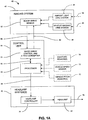
- Fig. 1A is an electrical block diagram of an exemplary imaging system
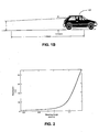
- Fig. 1B is a side view of a leading vehicle illustrating various geometric considerations
- Fig. 2 is a graph depicting the illumination, as a function of the mounting height of a trailing vehicle's low-beam headlamps, on a surface at a rearview mirror position of the leading vehicle of Fig. 1B ;
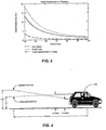
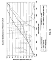
- Fig. 3 is a graph illustrating road surface illumination as a function of distance for various headlamp mounting heights
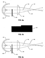
- Fig. 4 is a side view of another leading vehicle illustrating various geometric considerations
- Fig. 5 is a graph depicting the relationship of the position of an on-coming headlamp image, with respect to a center of the image, as captured by an array of sensors in a controlled vehicle, as a function of distance to an on-coming vehicle for various median widths;
- Fig. 6A is a side view of a high-performance headlamp that implements a mask, according to an embodiment of the present invention
- Fig. 6B is a front view of the mask of Fig. 6A ;
- Fig. 6C is a side view of a high-performance headlamp that implements a mask, according to another embodiment of the present invention.
- Figs. 7A-7B are front views of variable transmission devices that are used to control the illumination produced by headlamps of a vehicle, according to an embodiment of the present invention
- Fig. 8 is a side view of a headlamp that includes a plurality of individual light emitting diodes
- Fig. 9 is a diagram of a headlamp that utilizes a spatially controlled reflector
- Fig. 10 depicts plots of the spectral distributions of various vehicle exterior lights
- Fig. 11 depicts plots of the spectral reflectance ratios of various colored road signs
- Fig. 12 depicts plots of transmission factors of red and infrared filter material, according to an embodiment of the present invention.
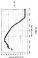
- Fig. 13 depicts plots of the quantum efficiency versus wavelength for an optical system, according to an embodiment of the present invention
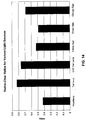
- Fig. 14 depicts a graph of red-to-clear ratios for various light sources as detected by an optical system, according to an embodiment of the present invention
- Fig. 15A is a side view of a headlamp that implements a rotatable mask, according to one embodiment of the present invention.
- Fig. 15B is a front view of the mask of Fig. 15A ;
- Fig. 16A is a side view of a headlamp that implements a rotatable mask, according to another embodiment of the present invention.
- Fig. 16B is a front view of the mask of Fig. 16A in a first position
- Fig. 16C is a front view of the mask of Fig. 16A in a second position.
- the present invention is directed to a system for controlling at least one exterior vehicle light (e.g., low-beam headlamps, high-beam headlamps, tail lamps, fog lamps, etc.) of a controlled vehicle and includes an array of sensors and a control unit.
- the control unit is in communication with the array of sensors and the at least one exterior vehicle light and is capable of determining a distance and an angle from the at least one exterior vehicle light of the controlled vehicle to a leading vehicle.
- the control unit is operable to control operation of the at least one exterior vehicle light as a function of the distance and angle, based on the output from the array of sensors, and prevent the at least one exterior vehicle light from providing disruptive glare to a driver of the leading vehicle.
- the control unit is operable to acquire and process electrical signals received from the array of sensors to determine an illumination gradient associated with the at least one exterior vehicle light on a road surface.
- the control unit compares a sensed illumination range, which is based on the illumination gradient, to a desired illumination range and is operable to control the at least one exterior vehicle light to achieve a desired illumination range.
- an illumination control system for controlling the at least one exterior vehicle light of a controlled vehicle includes a discrete light sensor and a control unit.
- the control unit is operable to acquire and process electrical signals from the discrete light sensor, which provides an indication of an AC component present in ambient light.
- the control unit causes the at least one exterior vehicle light to transition to the town lighting mode when the AC component exceeds a predetermined AC component threshold.
- the imaging system obtains an image to a front of the controlled vehicle and includes an array of sensors which each generate electrical signals that represent a light level sensed by the sensor.
- the control unit is operable to examine a position and brightness of an on-coming vehicle headlamp over time, as indicated by the electrical signals provided by the array of sensors, to determine when a median width is appropriate for the activation of a motorway lighting mode.
- a control system 40 for continuously variable headlamps includes imaging system 42, control unit 44 and at least one continuously variable headlamp system 46.
- the control unit 44 may take various forms, such as a microprocessor including a memory subsystem with an application appropriate amount of volatile and non-volatile memory, an application specific integrated circuit (ASIC) or a programmable logic device (PLD).
- the imaging system 42 includes vehicle imaging lens system 48 operative to focus light 50 from a region generally in front of a controlled vehicle onto image array sensor 52.
- the imaging system 42 is capable of determining lateral and elevational locations of headlamps from on-coming vehicles and tail lamps of leading vehicles.
- the vehicle imaging lens system 48 may include two lens systems, one lens system having a red filter and one lens system having a cyan filter, which permits the image array sensor 52 to simultaneously view a red image and a cyan image of the same region in front of the controlled vehicle and thereby discriminate between tail lamps and headlamps.
- the image array sensor 52 may include an array of pixel sensors.
- the imaging system 42 may include an ambient light lens system 54 operable to gather light 56 over a wide range of elevational angles for viewing by a portion of the image array sensor 52.
- the light 50 focused through the vehicle imaging lens system 48, may be used to determine ambient light levels.
- a light sensor completely separate from the imaging system 42 may be used to determine ambient light levels.
- the imaging system 42 is incorporated into an interior rearview mirror mount. In this case, the imaging system 42 may be aimed through a portion of the windshield of the controlled vehicle that is cleaned by at least one windshield wiper.
- the control unit 44 accepts pixel gray scale levels 58 and generates image sensor control signals 60 and headlamp illumination control signals 62.
- the control unit 44 includes an imaging array control and analog-to-digital converter (ADC) 64 and a processor 66.
- the processor 66 receives digitized image data from and sends control information to the imaging array control and ADC 64, via serial link 68.
- the control system 40 may include vehicle pitch sensors 70, to detect the pitch angle of a controlled vehicle relative to the road surface. Typically, two of the vehicle pitch sensors 70 are desired. Each of the sensors 70 are mounted on the chassis of the controlled vehicle, near the front or rear axle, and a sensor element is fixed to the axle. As the axle moves relative to the chassis, the sensor 70 measures either rotational or linear displacement. To provide additional information, the control unit 44 may also be connected to a vehicle speed sensor 72, one or more moisture sensors 74 and may also be connected to a GPS receiver, a compass transducer and/or a steering wheel angle sensor.
- Precipitation such as fog, rain or snow may cause excessive light from headlamps 22 to be reflected back to the driver of the controlled vehicle. Precipitation may also decrease the range at which on-coming vehicles and leading vehicles may be detected. Input from the moisture sensor 74 may therefore be used to decrease the full range of illumination.
- a headlamp controller 76 controls at least one of the continuously variable headlamps 22.
- each of the headlamp controllers 76 accepts the headlamp illumination control signals 62, from control unit 44, and affects the headlamps 22 accordingly to modify an illumination range of light 78 leaving headlamp 22.
- the headlamp controller 76 may vary the intensity of the light 78 leaving the headlamp 22, may vary the direction of the light 78 leaving the headlamp 22, or both.
- the control unit 44 may acquire an image covering a glare area, which includes points at which a driver of an on-coming vehicle or leading vehicle would perceive the headlamps 22 to cause excessive glare.
- the control unit 44 processes the image to determine if at least one vehicle is within the glare area. If at least one vehicle is within the glare area, the control unit 44 changes the illumination range. Otherwise, the headlamps 22 are set to a full illumination range.
- the changes to illumination range and setting the headlamps 22 to a full illumination range typically occur gradually as sharp transitions in the illumination range may startle the driver of the controlled vehicle, since the driver may not be aware of the precise switching time.
- a transition time of between one and two seconds is desired for returning to full illumination range from dimmed illumination range, corresponding to low-beam headlamps.
- Such soft transitions in illumination range also allow the control system 40 to recover from a false detection of an on-coming vehicle or leading vehicle. Since image acquisition time is approximately 30 ms, correction may occur without the driver of the controlled vehicle noticing any change.
- reducing illumination range may be accomplished by decreasing the intensity of high-beam headlamps 22 while increasing the intensity of low-beam headlamps 22.
- low-beam headlamps can be left on continuously for ambient light levels below a certain threshold.
- the aim of headlamp 22 may be moved away from the direction of an on-coming vehicle when the illumination range is reduced or changed. This allows the driver of the controlled vehicle to better see the edge of the road, road signs, pedestrians, animals and the like that may be on the curb side of the controlled vehicle.
- the control unit 44 may determine if any leading vehicle is in a curb lane on the opposite side of the controlled vehicle from on-coming traffic. If a leading vehicle is not in the curb lane, reducing the illumination range may include aiming headlamps 22 away from the direction of on-coming traffic. If a leading vehicle is detected in a curb lane, the illumination range may be reduced without changing the horizontal aim of headlamps 22.
- Fig. 1B depicts a leading vehicle 102 that is being followed by a trailing vehicle (not shown) at a distance of about 15 meters, with respect to low-beam headlamps of the trailing vehicle and an internal rearview mirror of the leading vehicle.
- the illumination at the leading vehicle's interior rearview mirror located about 1.2 meters above the road, is determined by: computing the horizontal and vertical angle to each of the headlamps (assuming a headlamp separation of about 1.12 m), determining the intensity of the headlamps at that angle and dividing the determined intensity by the distance squared.
- Information on the average position of automotive rearview mirrors can be obtained from a paper entitled " Field of View in Passenger Car Mirrors," by M. Reed, M. Lehto and M. Flannagan (published by the University of Michigan Transportation Research Institute [UMTRI-2000-23 ]).
- Information on the intensity of average low-beam headlamps can be obtained from a paper entitled " High-Beam and Low-Beam Headlighting Patterns in the U.S. and Europe at the Turn of the Millennium," by B. Schoettle, M. Sivak and M. Flannagan (published by UMTRI [UMTRI 2001-19 ]).
- Fig. 2 is a graph that depicts the illumination (as a function of mounting height of the trailing vehicle's low-beam headlamps) on a surface at the rearview mirror position of a leading vehicle, assuming no obstructions and based on the information set forth above.
- the graph of Fig. 2 illustrates the low-beam headlamp mounting height over the legal range, specified in FMVSS 108, of 0.56 meters to 1.37 meters.
- a typical passenger car may have headlamps mounted at about 0.62 meters.
- the glare on the rearview mirror of the leading vehicle is about 2.4 lux.
- the glare on the rearview mirror of the leading vehicle increases to 5.8 lux.
- FIG. 3 depicts three curves of road illumination as a function of distance for: a passenger car with low-beam headlamps mounted at 0.62 meters, a truck or SUV with low-beam headlamps mounted at 1 meter and a truck or SUV with low-beam headlamps mounted at 1 meter and aimed downward an additional 1.4 degrees.
- the downward aim reduces the visibility distance of the low-beam headlamps significantly.
- simply aiming the headlamps down is generally unacceptable during normal driving conditions, when no leading vehicle is present.
- SAE Society of Automotive Engineers
- Systems to vary the aim of headlamps are currently commercially available on many production vehicles. These systems typically use sensors in the axles of a vehicle to detect changes in road pitch and vary the aim of the headlamps to insure a constant visibility distance.
- Other systems provide motors for adjustment of the aim of the headlamps, but rely on the driver to manually adjust the aim of the headlamps through a manual adjustment knob located in the vehicle. Although such systems were not designed or used in conjunction with a means to detect a leading vehicle to automatically reduce the angle of the headlamps, when such vehicles are detected, such systems can be used for this purpose.
- such a leading vehicle detection means may include a camera (i.e., an array of sensors) and an image processing system as is described in U.S. Patent No. 6,281,632 entitled “CONTINUOUSLY VARIABLE HEADLAMP CONTROL,” issued August 28, 2001, to Joseph S. Stam et al., and PCT Application No. PCT/US01/08912 , entitled “SYSTEM FOR CONTROLLING EXTERIOR VEHICLE LIGHTS,” published September 27, 2001 ( WO 01/70538 ).
- Such systems are capable of detecting the tail lamps of leading vehicles and may determine the approximate distance to a leading vehicle by the brightness of the tail lamps in an image or by the separation distance between the two tail lamps of the leading vehicle. Since tail lamps are typically mounted below the rear window of most vehicles, the tail lamps' position in the image can also be used to determine if excess glare is likely to be projected into the rearview mirror of the leading vehicle.
- Fig. 4 depicts a leading vehicle 402 (with tail lamps located 1 meter above the road) whose rearview mirror is 15 meters ahead of low-beam headlamps of a trailing vehicle (not shown).
- the angle between the tail lamps of the leading vehicle and the camera of the trailing vehicle can be determined from the position of the tail lamps in the image. It should be appreciated that the difference in mounting height between a camera mounted within a vehicle and low-beam headlamps of the vehicle is fixed and, therefore, can be known for any given vehicle.
- the distance to the leading vehicle can be determined in a number of ways. For example, the distance to the leading vehicle can be estimated by the brightness of the tail lamps of the leading vehicle in the image.
- the distance between the two tail lamps can be used to estimate the distance to the leading vehicle.
- brightness can be used to estimate the distance between the trailing and leading vehicles.
- other devices for determining distance such as a radar, laser or ultrasonic sensors, may be used.
- Such systems are already incorporated in many production vehicles for use in conjunction with, for example, parking aids and adaptive cruise control systems. For an example of one such system see U.S. Patent No. 6,403,942 , entitled "AUTOMATIC HEADLAMP CONTROL SYSTEM
- the angle between the controlled vehicle's headlamps and the leading vehicle can be determined.
- a detailed method for analyzing an image to determine the location of light sources within an image is set forth in PCT Application No. PCT/US01/08912 . Then, if the trailing vehicle is close enough to the leading vehicle for glare to disrupt the driver of the leading vehicle, the aim of the headlamps can be set downward to a level which does not cause disruptive glare (alternatively, or in addition, the intensity of the headlamps may be adjusted).
- the headlamps of the trailing vehicle can be aimed normally for proper road illumination.
- Modifications to the above embodiment may include a variety of methods for reducing the intensity of light directed towards the detected light source. These methods include, but are not limited to: modifying the horizontal direction aim of the headlamps, modifying the vertical direction aim of the headlamps, modifying the intensity of the headlamps, enabling or disabling one of a plurality of exterior lights and selectively blocking or attenuating light from the exterior lights in the direction of the detected light source.
- Low-beam headlamps which are designed to prevent glare to on-coming drivers, are typically aimed 1.5 degrees downward and about 1.5 degrees right, with a sharp reduction in intensity above the peak.
- variations in the road and in vehicle loading can regularly cause the peak of these headlamps to shine directly into the eyes of an on-coming driver. This problem becomes much more severe with new technology headlamps, such as high-intensity discharge (HID) headlamps, and, as a result, various groups have attempted to design systems that perform active leveling of these brighter headlamps.
- HID high-intensity discharge
- An embodiment of the present invention generally improves on prior automatic headlamp leveling systems by sensing the actual beam pattern, provided by, for example, the low-beam headlamps, on the road separately, or in combination with the sensing of the vehicle's pitch. By looking at the illumination gradient on the road, it is possible to compare the actual illumination range to the desired illumination range and compensate for variance by adjusting the headlamp's aim.
- the desired illumination range may be constant or may be a function of the current vehicle speed, ambient light level, weather conditions (rain/fog/snow), the presence or absence of other vehicles, the type of roadway or other vehicle and/or environmental conditions.
- a driver of a vehicle traveling at a high rate of speed may benefit from a longer illumination range, while drivers traveling in fog may benefit from headlamps aimed lower.
- road reflectance is generally variable, it is not normally sufficient to look only at the illumination on the road to determine the illumination range. Rather, it is generally useful to look at the light level gradient with increasing distance on the road surface.
- road illumination decreases as the distance from the vehicle increases.
- the current aim of the headlamps can be determined and adjusted to provide a desired illumination range.
- a vertical linear array of photosensors can be used to image road illumination and, thus, provide the road illumination gradient.
- reflections from lane markings can be used to indicate when a road bend is ahead of the controlled vehicle such that a direction of the headlamps of the controlled vehicle can be controlled to bend with the road.
- a navigation system e.g. a land-based system (such as Loran) or satellite-based system (such as a global positioning system (GPS)
- GPS global positioning system
- Adaptive front lighting systems are a new generation of forward lighting systems, which contain a variety of technologies for improving a vehicle's forward illumination.
- AFS lighting systems may include, for example, the following illumination modes:
- the goal of a typical AFS lighting system is to provide automatic selection of the different lighting modes. For example, rain sensing or fog sensing can be used to activate bad weather lights and steering wheel angle can be used to activate bending lights.
- the activation of the other illumination modes is not as straight forward. That is, activation of motorway lighting modes and town lighting modes requires a knowledge of the environment. Vehicle speed can be used to activate town lighting; however, it is possible that the illumination range may be unnecessarily reduced when traveling at a low speed out of town. Also, ambient light level may be a useful indication of traveling in a town.
- 09/800,460 entitled "SYSTEM FOR CONTROLLING EXTERIOR LIGHTS," a vehicle including a global positioning system (GPS) with a map database indicating the types of roads on which a vehicle is traveling may be used to determine a proper mode of lighting.
- GPS global positioning system
- map data may not be available for all areas of the world.
- inaccuracies in GPS systems may occasionally cause such a system to incorrectly identify the road on which a vehicle is traveling.
- a town is detected through the use of an optical sensor.
- a discrete light sensor such as that described in PCT Application No. PCT/US00/00677 , entitled “PHOTODIODE LIGHT SENSOR,” by Robert H. Nixon et al. and published July 27, 2000 ( WO 00/43741 ) may be utilized.
- This sensor may be used to measure the ambient light and also measure the 120 Hz (or 100 Hz in Europe) intensity ripple component, produced by discharge street lighting powered by a 60 Hz AC source, by obtaining several light level measurements during different phases of the intensity ripple.
- the vehicle speed is low (for example, less than 30 mph) it is likely that the vehicle is traveling in a town with significant municipal lighting and town lighting can be activated.
- town driving conditions can be accurately determined.
- the magnitude of the AC component may be used in combination with the ambient light level and the vehicle's speed to make a proper determination of the use of town lighting. For example, if the ambient light level is sufficient such that there would not be a significant safety risk from the reduced illumination range, the speed of the vehicle is indicative of driving in a town (e.g., below about 30 mph) and there is a significant AC component in the ambient lighting, town lighting may be activated.
- the transition from normal low-beam lighting to town lighting may be continuous with the illumination range being a continuous function of ambient lighting and vehicle speed so as to produce a sufficient illumination range for given conditions.
- a sensor array such as an image sensor, may be used to identify street lamps and activate town lighting if the number of streetlamps detected in a period of time exceeds a threshold (along with consideration of the vehicle's speed and ambient lighting).
- the light sensor may be provided in various places throughout a motor vehicle, e.g., provided in a rearview mirror housing. Further, such a light sensor may also be used for various other functions (e.g., sun load), such as those set forth in U.S. Patent No. 6,379,013 , entitled “VEHICLE EQUIPMENT CONTROL WITH SEMICONDUCTOR LIGHT SENSORS.”
- Motorway conditions can be also be determined by using an image sensor to detect the lane separation or median of a motorway. This can be accomplished by directly looking at the angular movement of the headlamps of on-coming vehicles in several subsequent images. The detection of the movement of an object in a series of images is further described in U.S. Patent Application Serial No. 09/799,310 entitled "IMAGE PROCESSING SYSTEM TO CONTROL VEHICLE HEADLAMPS OR OTHER VEHICLE EQUIPMENT,” filed March 5, 2001, to Joseph S. Stam et al. Fig.
- FIG. 5 illustrates three curves, which represent different motorway median widths, and how the position of an on-coming headlamp in an image varies as a function of the distance between two vehicles that are traveling in different directions are converging.
- Fig. 6A schematically illustrates an exemplary high-performance headlamp, commonly referred to as a projector headlamp, which is utilized in conjunction with a mask 603.
- a bulb 602 is placed in front of a reflector 601.
- the bulb 602 may be of a conventional incandescent (e.g., tungsten-halogen) type, high-intensity discharge (HID) type or other suitable bulb type, or may be the output from a remote light source as is described further below.
- a lens 604 directs light from the bulb 602 and reflected by the reflector 601 down the road.
- the mask 603 establishes a cutoff point to prevent light above the horizon 605 from being directed down the road.
- the mask 603 absorbs or reflects light rays, such as light ray 607, which would cause glare to another vehicle.
- the mask 603, typically, has a shape, such as that shown in Fig. 6B , which contains a step allowing a slightly higher cutoff point to the right of the vehicle.
- a modification to this type of lamp construction includes a solenoid to control the mask 603.
- the mask 603 can be removed from the position in front of the bulb 602.
- rays such as the ray 607
- the lamp with mask 603 removed can function as a high-beam headlamp.
- the mask 603 may also be controlled by a motor to move vertically relative to the bulb 602, lens 604 and reflector 601, as shown in Fig. 6C .
- a motor to move vertically relative to the bulb 602, lens 604 and reflector 601, as shown in Fig. 6C .
- the cutoff angle is raised and the illumination range is extended.
- the cutoff angle is lowered and illumination range is reduced.
- the movement of the mask 603 can be used to establish different lighting functions, such as town or motorway lighting, or to increase the illumination range gradually with increased speed.
- the movement of the mask 603 can also be used to establish the vertical aim of the headlamp and therefore compensate for vehicle pitch variations as described herein above. This method of aiming the headlamp is advantageous because only the relatively small mask 603 requires movement, rather than the entire lamp set which is moved in some auto-leveling systems today.
- the mask 603 is replaced with a spatially controlled variable attenuating filter.
- This filter can be formed as an electrochromic variable transmission window, which has the capability to selectively darken various regions of the window.
- This window may contain a liquid or solid state (e.g., tungsten oxide) electrochromic material that is capable of withstanding the high temperatures achieved in close proximity to the bulb.
- this window may be a liquid crystal device (LCD), a suspended particle device or other electrically, chemically or mechanically variable transmission device.
- LCD liquid crystal device
- a suitable electrochromic device is disclosed in U.S. Patent No. 6,020,987 entitled "ELECTROCHROMIC
- variable transmission device 700 An example of such a variable transmission device 700 is shown in Figs. 7A and 7B .
- the device 700 is constructed using two pieces of glass with electrochromic material contained between.
- a transparent conductive electrode such as indium tin oxide (ITO)
- ITO indium tin oxide
- these regions are horizontal strips 701, which may optionally contain a slight step.
- the window 700 may contain several independently controlled blocks 702 as shown in Fig. 7B .
- distinct beam patterns may be achieved in various manners, e.g., changing the intensity or one or more light sources, changing the aiming direction of one or more light sources, changing the distribution of light provided by one or more light sources and/or activating multiple light sources in combination.
- mask 603 may be constructed as a spatially controlled reflector.
- a reflector may be a reversible electro-chemical reflector, such as that described in U.S. Patent Nos. 5,903,382 ; 5,923,456 ; 6,166,847 ; 6,111,685 and 6,301,039 .
- a reflective metal is selectively plated and de-plated on a surface to switch between a reflective and transmissive state.
- a metal-hydride switchable mirror available from Phillips electronics, may also be used to provide a spatially controlled reflector.
- the spatially controlled reflector may be formed as a single contiguous reflector, allowing for a switch from high to low-beam or may be patterned, such as in Figs. 7A and 7B , to allow activation of individual segments of the mirror and, thus, provide spatial control of the transmitted beam.
- the use of a spatially controlled mirror provides the advantage that a reflective device reflects light rays 607 back into reflector 601 and, thus, these rays are conserved, rather than absorbed and, as such, are available to be projected in other areas of the beam. This provides a headlamp with improved efficiency, as compared to headlamps that absorb light rays to provide a desired illumination pattern. Additionally, by reflecting light rays, rather than absorbing the light rays, the mask may not become as hot and, thus, the headlamp becomes potentially more robust.
- a spatially controlled reflector is used to construct a headlamp in accordance with Fig. 9 .
- a bulb 901 and reflector 902 form a light source, which projects incident rays 906 onto a spatially controlled reflector 903.
- the light source may be any type of light source suitable for automotive use, such as a halogen source, a high-intensity discharge (HID) source or a light emitting diode (LED) source.
- Incident rays 906 may also come from a remote light source through a fiber bundle or light pipe.
- the spatially controlled reflector 903 contains a plurality of switchable mirrors 905, which can be turned on and which reflect incident rays 906 (as reflected rays 907), which are then projected by lens 904 down the road. When turned off, the incident rays 906 are reflected away from the lens 904, transmitted through the reflector 903 or absorbed and, thus, not projected by the lens 904. Alternatively, the rays may be redirected to increase the illumination of other portions of a headlamp beam.
- the spatially controlled reflector may be, for example, a custom designed digital micro-mirror device (DMD) available from Texas Instruments.
- DMDs are micromachined arrays of tiny mirrors which can be switched between two angles and are currently widely used for video projectors.
- the application of a DMD to produce a spatially configurable headlamp is analogous to that of a video projector.
- high resolution, variable color and video frame rates that are necessary for video projectors are not necessary in a headlamp that utilizes a DMD.
- a control system for a headlamp can be simpler than a control system for a video projector.
- the present invention is not limited to any particular number of mirrors or switching rate. As few as one mirror for switching between two beam patterns to many thousands of mirror segments for providing a completely configurable beam pattern may be used.
- the spatially controlled reflector may be constructed as a reversible electro-chemical reflector or a metal-hydride switchable mirror as described above.
- a solid mirror with a patterned attenuating filter such as an electrochromic filter or LCD placed in front of the mirror may be used to provide the same function.
- controllable reflectors and/or attenuators may be used to select a beam pattern, based upon one or more driving conditions, at which point a control unit (based upon input received from a sensor array) may cause the reflector and/or attenuator to redirect or inhibit light that would cause glare to a sensed object.
- systems implementing a control unit in conjunction with a sensor array are configurable to distinguish between reflected light and light from another light source, through manipulation of a light source or sources of a controlled vehicle headlamp.
- the light source(s) of the headlamp embodiments of Figs. 8 and 9 can be cycled such that reflected light can be distinguished from light from another light source.
- the embodiment of Figs. 7A-7B may also be cycled to distinguish reflected light from light from another light source.
- the embodiment of Fig. 9 generally functions in a similar manner as the previously described embodiments.
- the lamp can provide a basic low-beam function and/or provide high-beams, bending lamps, motorway lighting, bad weather lighting or any intermediate state.
- mirrors when used with a camera to detect the direction to other vehicles, mirrors can be turned off to prevent light rays in that direction from being projected and, thus, glaring the other vehicle.
- the mirrors may be controlled such that reflected light, e.g., a non-vehicular light source can be distinguished from light provided by another light source, e.g., a vehicular light source.
- FIG. 8 Yet another headlamp configuration suitable for use with the present invention is described with reference to Fig. 8 .
- the reflector 601, bulb 602, and mask 603 are replaced by a high-intensity LED array 801, which is placed approximately in the focal plane of the lens 604.
- High intensity LED arrays suitable for use as automotive headlamps are described in PCT application PCT/US01/08912 , and in U.S. Patent Application 09/835,238 to Roberts et al., filed April 13, 2001 . These arrays may produce white light illumination through a binary-complementary combination of amber and blue-green LED emitters.
- LEDs 802 or groups of LEDs 802 in the LED array 801 are configured to be independently, and optionally variably, energized by electronic control unit.
- the light from LEDs 802 (or groups of closely spaced LEDs) is projected to a particular region in front of the lamp by the lens 604.
- a desired beam pattern can be achieved in a fashion similar to that achieved by selectively darkening various blocks 702 in the previously described embodiment of Fig. 7B .
- all LEDs below a cutoff point may be energized to produce a desired illumination range.
- LEDs which project light in the direction of the identified vehicle may be shut off or reduced in intensity to prevent glare to the vehicle.
- All other LEDs may remain lit to provide illumination in regions where no vehicles are present.
- a portion of the LEDs can be dimmed or turned off to distinguish on-coming vehicles from other light sources, such as reflectors.
- the above described embodiments provide headlamps with a controllable and reconfigurable beam pattern. These headlamps may be used with the methods described above to provide a fully automatic vehicle forward light system, which can provide numerous functions, including: low-beams, high-beams, motorway lighting, town lighting, bad weather lighting, bending lamps, auto leveling and anti-glare control to prevent glare to on-coming or preceding drivers. These particular lighting modes are only exemplary and control may switch between discrete modes or may be continuous.
- a variety of sensors may provide input to a control system to determine the appropriate beam pattern for the given driving conditions.
- These sensors may include, for example, a camera, ambient light sensor, speed sensor, steering wheel angle sensor, temperature sensor, compass, a navigation system (e.g., a land-based (such as Loran) or satellite-based (such as GPS), pitch sensors and various user input switches.
- a driver input may be provided for setting various preferences, such as the thresholds for switching between various beam patterns, the brightness of the lamps, the sharpness of beam cutoffs, the color of the lamps, the degree of bending, etc.
- a GPS, user input or factory setting may be provided to indicate the location of the vehicle to ensure compliance with various laws. Thus, identical lamp assemblies may be used in various countries with a simple selection of location.
- control methods described herein may be utilized with the lamp embodiments described herein or with other lamp types. Similarly, the lamp embodiments described herein may be controlled by a variety of methods. Finally, the lamp embodiments described herein may be used alone, in any number or configuration, or in conjunction with standard lamps, fixed bending lamps, fog lamps, foul weather lamps or other types of lamps. The control methods may control both the configurable lamps and any other type of lamp.
- various external vehicle lights are used, such as high-intensity discharge (HID) headlamps, tungsten-halogen and blue-enhanced halogen headlamps, to provide greater ability to distinguish reflections from various roadside reflectors and signs from headlamps of on-coming vehicles and tail lamps of leading vehicles.
- HID high-intensity discharge
- tungsten-halogen and blue-enhanced halogen headlamps to provide greater ability to distinguish reflections from various roadside reflectors and signs from headlamps of on-coming vehicles and tail lamps of leading vehicles.
- specific spectral filter material may be employed in combination with the external vehicle lights to produce desired results.
- Fig. 10 depicts plots of the spectral content of different types of vehicular related light sources and Fig. 11 depicts plots of the spectral reflectance of various colored signs.
- Fig. 12 depicts plots of the percent transmission of red and infrared spectral filters used in one embodiment of the present invention and
- Fig. 13 depicts a plot of the quantum efficiency of an optical system in accordance with an embodiment of the present invention. Numerical data depicted by the plots of Figs. 10-13 is utilized, as described in further detail below, to categorize various light sources.
- the brightness of a given detected light source can be estimated by multiplying the spectral output of the source, as shown in Fig. 10 , by the infrared spectral filter transmission factor, as shown in Fig. 12 , multiplied by the spectral response of the pixel array, as shown in Fig. 13 .
- this value is further multiplied by the transmission factor of the red spectral filter.
- the brightness of detected reflections from road signs can be estimated by multiplying the controlled vehicle's headlamp spectral output, as shown in Fig. 10 , by the spectral reflectance factor of the sign, as shown in Fig. 11 , the infrared spectral filter transmission factor, as shown in Fig. 12 , and the spectral response of the optical system, as shown in Fig. 13 .
- the preceding result is then multiplied by the red spectral filter transmission factor, as shown in Fig. 12 .
- the ratio in brightness between the object projected onto the red filtered pixels in relation to the object projected onto the non-red filtered pixels can be used to determine the relative redness of an object. This ratio can then be utilized to determine if the object is a tail lamp or a headlamp.
- Fig. 14 depicts the computed ratios of the brightness of objects projected onto red filtered pixels relative to those same objects projected onto the non-filtered pixels. As is shown in Fig. 14 , tail lamps have a much higher red-to-clear ratio than headlamps, or most other objects.
- HIR halogen-infrared
- HIR bulbs have the advantage of emitting less red light as a percentage of their total output, as shown in Fig. 10 .
- the image of signs reflecting light will have a lower brightness on red filtered pixels than on non-red filtered pixels.
- Other light sources which emit less red light in proportion to the total amount of light, may be advantageously used to minimize the false detection of road signs and reflections off of other objects; HID high-beam lights and LED headlamps are examples of such sources.
- white light sources such as headlamps
- Light sources with a high color temperature have a more bluish hue and are, misleadingly, typically called “cool-white light” sources.
- Light sources with a more yellow or orangish hue have a lower color temperature and are, also misleadingly, called “warm white light” sources.
- Higher color temperature light sources have a relatively higher proportion of short wavelength visible light to long wavelength visible light. The present invention can benefit from the use of higher color temperature headlamps due to the reduced proportion of red light that will be reflected by signs or other objects that could potentially be detected.
- Correlated color temperature for non-perfect Planckian sources can be estimated by computing the color coordinates of the light source and finding the nearest temperature value on the Planckian locus. Calculation of color coordinates is well known in the art.
- the text entitled MEASURING COLOUR, second edition, by R. W. G. Hunt, is one source for known teachings in the calculation of color coordinates.
- the present invention can benefit when the controlled vehicle is equipped with headlamps having a correlated color temperature above about 3500 Kelvin.
- Fig. 15A schematically illustrates a headlamp 1500, which includes a rotatable mask 1503 and a bulb 1502 that is positioned in front of a reflector 1501.
- the bulb 1502 may be of a conventional incandescent (e.g., tungsten-halogen) type, high-intensity discharge (HID) type or other suitable bulb type, or may be the output from a remote light source as is described above.
- a lens 1504 directs light from the bulb 1502 and reflected by the reflector 1501 down the road.
- the mask 1503 establishes a cutoff point to prevent light vertically above the horizon 1505 from being directed down the road.
- the mask 1503 absorbs or reflects light rays, such as light ray 1507, which may cause glare to another vehicle and allows an illumination pattern provided by the headlamp 1500 to be changed.
- the mask 1503 may have a number of different shapes, such as the oval shown in Fig. 15B , and may be implemented as an irregular cylinder that is coupled to a motor M, e.g., a stepper-motor, off-center so as to achieve a variable illumination pattern as the mask 1503 is rotated, i.e., the mask 1503 changes how much light is blocked as it is rotated. In this manner, the mask 1503 can provide an oblong profile in the vertical direction, when the mask 1503 is implemented as an oval cylinder.
- a motor M e.g., a stepper-motor
- a control unit receives electrical signals from a sensor array and controls the rotated position of the mask 1503, by sending control signals to the motor M, to achieve a desired illumination pattern.
- a homing or feedback technique may be employed to assure that the mask 1503 is in a known position and, thus, able to provide a desired illumination pattern.
- the rotation of the mask 1503 can be used to establish a vertical aim of the headlamp 1500, vehicle pitch variation compensation, as described herein above, can also be achieved. This technique of aiming a headlamp is advantageous as only the relatively small mask 1503 requires movement, rather than the entire lamp set which is moved in some commercially available auto-leveling systems.
- Fig. 16A schematically illustrates a headlamp 1600, which includes a rotatable mask 1603 that includes a plurality of profiles, according to another embodiment of the present invention. These profiles allow an illumination pattern to be controlled in both horizontal and vertical directions.
- the headlamp 1600 includes a bulb 1602 that is placed in front of a reflector 1601.
- the bulb 1602 may be of a conventional incandescent (e.g., tungsten-halogen) type, high-intensity discharge (HID) type or other suitable bulb type, or may be the output from a remote light source as is described above.
- a lens 1604 directs light from the bulb 1602 and reflected by the reflector 1601 down the road.
- the mask 1603 establishes a cutoff point to prevent light above the horizon 1605 from being directed down the road.
- the mask 1603 absorbs or reflects light rays, such as light ray 1607, which would cause glare to another vehicle.
- Light rays, such as light ray 1606, which project below the cutoff point, pass through the lens 1604 as they are not blocked by the mask 1603.
- the mask 1603 may simultaneously have a number of different incorporated profiles, such as the profiles shown in Figs. 16B and 16C , and is coupled to a motor M, e.g. a stepper-motor, at an end so as to achieve a variable illumination pattern as the mask 1603 is rotated to select a desired profile. For example, by providing different horizontal profiles one can effect where light is aimed, e.g., left or right, and/or change the width of a light beam. Similar to the headlamp 1500, the headlamp 1600 may function with a control unit that receives electrical signals from a sensor array and controls the rotated position of the mask 1603, by sending control signals to the motor M, to achieve a desired illumination pattern. It should be appreciated that a homing or feedback technique may also be employed to assure that the mask 1603 is in a known position and, thus, able to provide a desired illumination pattern.
- a homing or feedback technique may also be employed to assure that the mask 1603 is in a known position and, thus, able to
- the rotation of the mask 1603 can also be used to establish different lighting functions, such as town or motorway lighting, or to increase the illumination range gradually with increased speed. Additionally, the rotation of the mask 1603 can also be used to establish both vertical and horizontal aim of the headlamp and therefore also compensate for vehicle pitch variations, as described herein above. This method of aiming the headlamp is also advantageous due to the fact that only the relatively small mask 1603 requires rotation.
- a system for controlling at least one exterior vehicle light of a controlled vehicle comprises an array of sensors capable of detecting light levels in front of the controlled vehicle; and a control unit in communication with the array of sensors and the at least one exterior vehicle light, the control unit determining a distance and an angle from the at least one exterior vehicle light of the controlled vehicle to a leading vehicle, wherein the control unit is operable to control operation of the at least one exterior vehicle light as a function of the distance and angle based on output from the array of sensors and prevent the at least one exterior vehicle light from providing a disruptive glare to a driver of the leading vehicle.
- the at least one exterior vehicle light may include two low-beam headlamps.
- the control unit may prevent the disruptive glare by causing the at least one exterior vehicle light to be one of aimed downward and reduced in intensity.
- the control unit may determine the distance to a leading vehicle by determining one of the brightness of a tail lamp of the leading vehicle, determining the distance between two tail lamps of the leading vehicle and utilizing an output signal provided by one of a radar, laser and ultrasonic sensor.
- the array of sensors may be a two-dimensional array of sensors that is incorporated within a camera.
- the at least one exterior light may be a headlamp that provides illumination at more than two distinct beam patterns.
- the array of sensors may be a two-dimensional array of sensors that is incorporated within a camera.
- said control unit may comprise a processor and a memory subsystem for storing processor executable code coupled to the processor, the processor executable code when executed causing the processor to perform the steps of determining a distance and an angle from the at least one exterior vehicle light of the controlled vehicle to a leading vehicle based on output from an array of sensors; and controlling the operation of the at least one exterior vehicle light as a function of the distance and angle to prevent the at least one exterior vehicle light from providing a disruptive glare to a driver of the leading vehicle.
- the processor may prevent the disruptive glare by causing the at least one exterior vehicle light to be one of aimed downward and reduced in intensity.
- the processor may determine the distance to a leading vehicle by determining one of the brightness of a tail lamp of the leading vehicle, determining the distance between two tail lamps of the leading vehicle and utilizing an output signal provided by one of a radar, laser and ultrasonic sensor.
- a first illumination control system for controlling at least one exterior vehicle light of a controlled vehicle comprises an array of sensors for generating electrical signals; and a control unit in communication with the at least one exterior vehicle light and operable to acquire and process electrical signals received from the array of sensors to determine an illumination gradient associated with the at least one exterior vehicle light on a road surface, the control unit comparing a sensed illumination range, which is based on the illumination gradient, to a desired illumination range and being operable to control the at least one exterior vehicle light to achieve the desired illumination range.
- the at least one exterior vehicle light may include two low-beam headlamps.
- the control unit may achieve the desired illumination range and may prevent disruptive glare by controlling at least one of an aim and intensity of the at least one exterior vehicle light.
- the control unit may determine a distance to a leading vehicle by at least one of determining the brightness of a tail lamp of the leading vehicle, determining the distance between two tail lamps of the leading vehicle and utilizing an output signal provided by one of a radar, laser and ultrasonic sensor.
- the array of sensors may be a two-dimensional array of sensors.
- the desired illumination range may be based on at least one of a constant, a controlled vehicle speed, an ambient light level, weather conditions, a presence of another vehicle, an absence of another vehicle and a type of roadway.
- a second illumination control system for controlling at least one exterior vehicle light of a controlled vehicle comprises a discrete light sensor for generating electrical signals; and a control unit in communication with the at least one exterior vehicle light and operable to acquire and process electrical signals received from the discrete light sensor to determine when the at least one exterior vehicle light should transition to a town lighting mode, wherein the discrete light sensor provides an indication of an AC component present in ambient light, and wherein the control unit causes the at least one exterior vehicle light to transition to the town lighting mode when the AC component exceeds a predetermined AC component threshold.
- the at least one exterior vehicle light includes two low-beam headlamps.
- the second illumination control system may further comprise a vehicle speed sensor coupled to the control unit and providing an indication of a speed of the controlled vehicle, wherein the control unit only causes the at least one exterior vehicle light to transition to the town lighting mode when the speed of the controlled vehicle is below a controlled vehicle speed threshold.
- a third illumination control system for controlling at least one exterior vehicle light of a controlled vehicle comprises an imaging system for obtaining an image to a front of the controlled vehicle, the imaging system including an array of sensors each generating electrical signals representing a light level sensed by the sensor; and a control unit in communication with the at least one exterior vehicle light and operable to acquire electrical signals received from the array of sensors and to separately process the electrical signals, wherein the control unit is operable to examine a position and brightness of an on-coming vehicle headlamp over time, as indicated by the electrical signals provided by the array of sensors to determine when a median width is appropriate for the activation of a motorway lighting mode, and wherein the control unit causes the at least one vehicle light to transition to the motorway lighting mode responsive to the determined median width.
- the at least one exterior vehicle light may include two low-beam headlamps.
- said control unit may comprise a processor and a memory subsystem for storing processor executable code coupled to the processor, the processor executable code when executed causing the processor to perform the steps of: examining a position and brightness of an on-coming vehicle headlamp over time, as indicated by electrical signals provided by an array of sensors, to determine when a median width is appropriate for the activation of a motorway lighting; and causing the at least one vehicle light to transition to the motorway lighting mode responsive to the determined median width.
- a fourth illumination control system for controlling at least one exterior vehicle light of a controlled vehicle comprises an imaging system for obtaining an image to a front of the controlled vehicle, the imaging system including an array of sensors each generating electrical signals representing a light level sensed by the sensor; at least one spatially controlled device selected from the group comprising a spatially controlled variable attenuating filter, a spatially controlled reflector and a spatial light modulator; said spatially controlled device is positioned proximate the at least one exterior vehicle light; and a control unit in communication with the at least one exterior vehicle light and the at least one spatially controlled device, wherein the control unit is operable to acquire electrical signals received from the array of sensors and to process the electrical signals and control the at least one spatially controlled device to vary an illumination range of the at least one exterior vehicle light in response to the electrical signals, and wherein the control unit is operable to control the at least one spatially controlled device to distinguish between vehicular and non- vehicular light sources.
- the attenuating filter may be one of a liquid crystal device and an electrochromic device. In the fourth illumination control system, the attenuating filter may be controlled to vary the direction of the at least one exterior vehicle light in response to the electrical signals.
- the array of sensors may be incorporated within a camera.
- the reflector may be a metal-hydride switchable mirror. In the fourth illumination control system, the reflector may be a digital micro-mirror device. In the fourth illumination control system, the reflector may be also controlled to vary the direction of the at least one exterior vehicle light in response to the electrical signals. In the fourth illumination control system, the array of sensors may be incorporated within a camera.
- the at least one exterior vehicle light may be a headlamp and the reflector may be incorporated within the headlamp.
- said control unit may comprise a processor and a memory subsystem for storing processor executable code coupled to the processor
- said spatially controlled device may be a spatial light modulator and the processor executable code when executed may cause the processor to perform the steps of: receiving electrical signals from an array of sensors; controlling said spatial light modulator to vary an illumination pattern of the at least one exterior vehicle light in response to the received electrical signals.
- the spatial light modulator may be also controlled to provide redirected light to a portion of the spatial light modulator that is contributing to the illumination pattern provided by the at least one exterior light.
- a system for controlling at least one headlamp of a controlled vehicle comprises an array of sensors capable of detecting light levels in front of the controlled vehicle; and a control unit in communication with the array of sensors and the at least one headlamp, the headlamp having a high color temperature and the control unit receiving data representing the light levels detected by the array of sensors to identify potential light sources, the control unit distinguishing light that is emitted from the headlamp and reflected by an object from other potential light sources, wherein the control unit is operable to control operation of the at least one headlamp as a function of the light levels output from the array of sensors.
- the color temperature may be greater than 3500 Kelvin.
- the color temperature may be 3700 Kelvin.
- the color temperature may be greater than 4500 Kelvin.
- the at least one headlamp may be a high-intensity discharge headlamp.
- the at least one headlamp may be at least one light emitting diode.
- the at least one headlamp may be a halogen-infrared headlamp.
- the at least one headlamp may be a halogen headlamp.
- the at least one headlamp may be a blue-enhanced halogen headlamp.
- a first controllable headlamp comprises at least one light source; and a spatially controlled device selected from the group comprising a spatially controlled variable attenuating filter and a spatially controlled reflector; said spatially controlled device is positioned proximate the at least one light source, wherein the spatially controlled device is controlled to provide a variable illumination range for the at least one light source, and wherein the spatially controlled device is controlled to distinguish between vehicular and non-vehicular light sources.
- the attenuating filter may be one of a liquid crystal device and an electrochromic device.
- the spatially controlled device may be an attenuating filter and the attenuating filter may be controlled to vary the direction of the at least one light source in response to the electrical signals.
- the array of sensors may be incorporated within a camera.
- the reflector may be a metal-hydride switchable mirror.
- the reflector may be a digital micro-mirror device.
- the spatially variable device may be a reflector and the reflector may be also controlled to vary the direction of the at least one light source in response to the electrical signals.
- a second controllable headlamp comprises at least one light source; and a rotatable mask positioned proximate the at least one light source, wherein a control unit that is in communication with the at least one light source and the rotatable mask is operable to acquire electrical signals which correspond to light levels sensed by an array of sensors and to process the electrical signals and control the rotatable mask to vary an illumination range of the at least one light source in response to the electrical signals.
- the rotatable mask may include a plurality of profiles and may be coupled at an end to a motor that is coupled to the control unit, and wherein each of the profiles provides a different illumination pattern.
- a control system for controlling at least one exterior vehicle light of a controlled vehicle comprises a processor; and a memory subsystem for storing processor executable code coupled to the processor, the processor executable code when executed causing the processor to perform the steps of: determining an illumination gradient associated with the at least one exterior vehicle light on a road surface based on output from an array of sensors; comparing a sensed illumination range, which is based on the illumination gradient, to a desired illumination range; and controlling the at least one exterior vehicle light to achieve the desired illumination range.
- the processor may achieve the desired illumination range and may prevent disruptive glare by controlling at least one of an aim and intensity of the at least one exterior vehicle light.
- the processor may determine a distance to a leading vehicle by at least one of determining the brightness of a tail lamp of the leading vehicle, determining the distance between two tail lamps of the leading vehicle and utilizing an output signal provided by one of a radar, laser and ultrasonic sensor.
- the desired illumination range may be based on at least one of a constant, a controlled vehicle speed, an ambient light level, weather conditions, a presence of another vehicle, an absence of another vehicle and a type of roadway.
- a method for controlling the forward lighting of a motor vehicle comprises the steps of: receiving a vehicular input that includes at least one of a vehicle speed, a vehicle turn rate, a vehicle wheel angle, a vehicle compass direction, a vehicle pitch, a vehicle location, a weather condition and an ambient light level; determining a desired beam pattern based upon the vehicular input; receiving an image of a forward field of view of the motor vehicle from an image sensor; analyzing the received image; and modifying the desired beam pattern based upon the analyzed image, wherein more than two distinct beam patterns can be provided.
- the analyzing step may include detecting oncoming or preceding vehicle light sources.
- the beam pattern may be modified to prevent glare to detected oncoming or preceding vehicles.
- the analyzing step may include determining a light gradient on a road.
- the beam pattern may be modified to achieve the desired illumination range based upon the light gradient on the road.
Abstract
Description
- The present invention is generally directed to controlling exterior vehicle lights of a motor vehicle and, more specifically, to controlling exterior vehicle lights of a motor vehicle so as to reduce glare to occupants of other motor vehicles and/or pedestrians, as well as providing optimal lighting for various roads/environmental conditions.
- Currently, rearview mirror glare from trailing vehicles is a significant safety and nuisance concern, while driving at night. Sport utility vehicles (SUVs) and trucks, which generally have headlamps mounted much higher than passenger vehicles, may provide a much higher level of rearview glare than typical passenger cars. This glare may be especially disruptive in busy traffic situations where an SUV or truck is following a small passenger car. As a result of the glare experienced by drivers of passenger cars, when closely followed by an SUV or truck, various solutions, such as reducing the mounting height limit of headlamps, have been proposed to help alleviate this problem. Unfortunately, solutions such as reducing the mounting height limit of an SUV or truck's headlamps may generally require an objectionable change to the front end styling of the SUV or truck. Additionally, the physical construction of large SUVs and trucks may make it impossible to reduce the mounting height significantly.
- Thus, what is needed is a technique for reducing the glare caused by low-beam headlamps of SUVs and trucks that does not involve lowering the mounting height of low-beam headlamps of the SUV/truck. Further, it would be desirable for the technique to function with both leading and on-coming vehicles and be applicable to all vehicle types, roads and environmental conditions.
- An embodiment of the present invention is directed to a system for controlling at least one exterior vehicle light of a controlled vehicle and includes an array of sensors and a control unit. The array of sensors is capable of detecting light levels in front of the controlled vehicle. The control unit is in communication with the array of sensors and the at least one exterior vehicle light and determines an approximate distance and an angle from the at least one exterior vehicle light of the controlled vehicle to a leading vehicle. The control unit is also operable to control operation of the at least one exterior vehicle light as a function of the distance and angle, based on output from the array of sensors, and prevent the at least one exterior vehicle light from providing disruptive glare to a driver of the leading vehicle.
- According to another embodiment of the present invention, an illumination control system for controlling at least one exterior vehicle light of a controlled vehicle includes an array of sensors and a control unit. The array of sensors generates electrical signals that are provided to the control unit, which is in communication with the at least one exterior vehicle light. The control unit is operable to acquire and process electrical signals received from the array of sensors to determine an illumination gradient associated with the at least one exterior vehicle light on a road surface. The control unit compares a sensed illumination range, which is based on the illumination gradient, to a desired illumination range and is operable to control the at least one exterior vehicle light to achieve a desired illumination range.
- According to another embodiment of the present invention, an illumination control system for controlling at least one exterior vehicle light of a controlled vehicle includes a discrete light sensor and a control unit. The discrete light sensor generates electrical signals, which are provided to the control unit, which is in communication with the at least one exterior vehicle light. The control unit is operable to acquire and process electrical signals from the discrete light sensor to determine when the at least one exterior vehicle light should transition to a town lighting mode. The discrete light sensor provides an indication of an AC component present in ambient light and the control unit causes the at least one exterior vehicle light to transition to the town lighting mode when the AC component exceeds a predetermined AC component threshold.
- According to still another embodiment of the present invention, an illumination control system for controlling the at least one exterior vehicle light of a controlled vehicle includes an imaging system and a control unit. The imaging system obtains an image to a front of the controlled vehicle and includes an array of sensors, which each generate electrical signals that represent a light level sensed by the sensor. The control unit is in communication with the at least one exterior vehicle light and is operable to acquire electrical signals received from the array of sensors and to separately process the electrical signals. The control unit is operable to examine a position and brightness of an on-coming vehicle headlamp over time, as indicated by the electrical signals provided by the array of sensors, to determine when a median width is appropriate for the activation of a motorway lighting mode and causes the at least one exterior vehicle light to transition to the motorway lighting mode responsive to the determined median width.
- In another embodiment, an illumination control system for controlling at least one exterior vehicle light of a controlled vehicle includes an imaging system, a spatially controlled variable attenuating filter and a control unit. The imaging system obtains an image to a front of the controlled vehicle and includes an array of sensors that each generate electrical signals representing a light level sensed by the sensor. The filter is positioned approximate the at least one exterior vehicle light and the control unit is in communication with the at least one exterior vehicle light and the filter. The control unit is operable to acquire electrical signals received from the array of sensors and to process the electrical signals and control the filter to vary an illumination range of the at least one exterior vehicle light in response to the electrical signals and to control the filter to distinguish between vehicular and non-vehicular light sources.
- In one embodiment, an illumination control system for controlling at least one exterior vehicle light of a controlled vehicle includes an imaging system, a spatially controlled reflector and a control unit. The imaging system obtains an image to a front of the controlled vehicle and includes an array of sensors that each generate electrical signals representing a light level sensed by the sensor. The reflector is positioned approximate the at least one exterior vehicle light and the control unit is in communication with the at least one exterior vehicle light and the reflector. The control unit is operable to acquire electrical signals received from the array of sensors and to process the electrical signals and control the reflector to vary an illumination range of the at least one exterior vehicle light in response to the electrical signals and to control the reflector to distinguish between vehicular and non-vehicular light sources.
- In another embodiment, a system for controlling at least one headlamp of a controlled vehicle includes an array of sensors and a control unit. The array of sensors is capable of detecting light levels in front of the controlled vehicle and the control unit is in communication with the array of sensors and the at least one headlamp. The headlamp has a high color temperature and the control unit receives data representing the light levels detected by the array of sensors to identify potential light sources and distinguish light that is emitted from the headlamp and reflected by an object from other potential light sources. The control unit is also operable to control operation of the at least one headlamp as a function of the light levels output from the array of sensors.
- In yet another embodiment a controllable headlamp includes at least one light source and a spatially controlled variable attenuating filter positioned approximate the at least one light source. The filter is controlled to provide a variable illumination range for the at least one light source and is controlled to distinguish between vehicular and non-vehicular light sources.
- In still another embodiment, a controllable headlamp includes at least one light source and a spatially controlled reflector positioned approximate the at least one light source. The reflector is controlled to provide a variable illumination range for the at least one light source and is controlled to distinguish between vehicular and non-vehicular light sources.
- These and other features, advantages and objects of the present invention will be further understood and appreciated by those skilled in the art by reference to the following specification, claims and appended drawings.
- In the drawings:
-
Fig. 1A is an electrical block diagram of an exemplary imaging system; -
Fig. 1B is a side view of a leading vehicle illustrating various geometric considerations; -
Fig. 2 is a graph depicting the illumination, as a function of the mounting height of a trailing vehicle's low-beam headlamps, on a surface at a rearview mirror position of the leading vehicle ofFig. 1B ; -
Fig. 3 is a graph illustrating road surface illumination as a function of distance for various headlamp mounting heights; -
Fig. 4 is a side view of another leading vehicle illustrating various geometric considerations; -
Fig. 5 is a graph depicting the relationship of the position of an on-coming headlamp image, with respect to a center of the image, as captured by an array of sensors in a controlled vehicle, as a function of distance to an on-coming vehicle for various median widths; -
Fig. 6A is a side view of a high-performance headlamp that implements a mask, according to an embodiment of the present invention; -
Fig. 6B is a front view of the mask ofFig. 6A ; -
Fig. 6C is a side view of a high-performance headlamp that implements a mask, according to another embodiment of the present invention; -
Figs. 7A-7B are front views of variable transmission devices that are used to control the illumination produced by headlamps of a vehicle, according to an embodiment of the present invention; -
Fig. 8 is a side view of a headlamp that includes a plurality of individual light emitting diodes; -
Fig. 9 is a diagram of a headlamp that utilizes a spatially controlled reflector; -
Fig. 10 depicts plots of the spectral distributions of various vehicle exterior lights; -
Fig. 11 depicts plots of the spectral reflectance ratios of various colored road signs; -
Fig. 12 depicts plots of transmission factors of red and infrared filter material, according to an embodiment of the present invention; -
Fig. 13 depicts plots of the quantum efficiency versus wavelength for an optical system, according to an embodiment of the present invention; -
Fig. 14 depicts a graph of red-to-clear ratios for various light sources as detected by an optical system, according to an embodiment of the present invention; -
Fig. 15A is a side view of a headlamp that implements a rotatable mask, according to one embodiment of the present invention; -
Fig. 15B is a front view of the mask ofFig. 15A ; -
Fig. 16A is a side view of a headlamp that implements a rotatable mask, according to another embodiment of the present invention; -
Fig. 16B is a front view of the mask ofFig. 16A in a first position; and -
Fig. 16C is a front view of the mask ofFig. 16A in a second position. - The present invention is directed to a system for controlling at least one exterior vehicle light (e.g., low-beam headlamps, high-beam headlamps, tail lamps, fog lamps, etc.) of a controlled vehicle and includes an array of sensors and a control unit. The control unit is in communication with the array of sensors and the at least one exterior vehicle light and is capable of determining a distance and an angle from the at least one exterior vehicle light of the controlled vehicle to a leading vehicle. The control unit is operable to control operation of the at least one exterior vehicle light as a function of the distance and angle, based on the output from the array of sensors, and prevent the at least one exterior vehicle light from providing disruptive glare to a driver of the leading vehicle.
- In another embodiment of the present invention, an illumination control system for controlling the at least one exterior vehicle light of a controlled vehicle includes an array of sensors and a control unit. The control unit is operable to acquire and process electrical signals received from the array of sensors to determine an illumination gradient associated with the at least one exterior vehicle light on a road surface. The control unit compares a sensed illumination range, which is based on the illumination gradient, to a desired illumination range and is operable to control the at least one exterior vehicle light to achieve a desired illumination range.
- In yet another embodiment of the present invention, an illumination control system for controlling the at least one exterior vehicle light of a controlled vehicle includes a discrete light sensor and a control unit. The control unit is operable to acquire and process electrical signals from the discrete light sensor, which provides an indication of an AC component present in ambient light. The control unit causes the at least one exterior vehicle light to transition to the town lighting mode when the AC component exceeds a predetermined AC component threshold.
- According to still another embodiment of the present invention, an illumination control system for controlling the at least one exterior vehicle light of a controlled vehicle includes an imaging system and a control unit. The imaging system obtains an image to a front of the controlled vehicle and includes an array of sensors which each generate electrical signals that represent a light level sensed by the sensor. The control unit is operable to examine a position and brightness of an on-coming vehicle headlamp over time, as indicated by the electrical signals provided by the array of sensors, to determine when a median width is appropriate for the activation of a motorway lighting mode.
- Referring now to
FIG. 1A , a block diagram of a control system according to an embodiment of the present invention is shown. Acontrol system 40 for continuously variable headlamps includesimaging system 42,control unit 44 and at least one continuouslyvariable headlamp system 46. Thecontrol unit 44 may take various forms, such as a microprocessor including a memory subsystem with an application appropriate amount of volatile and non-volatile memory, an application specific integrated circuit (ASIC) or a programmable logic device (PLD). Theimaging system 42 includes vehicleimaging lens system 48 operative to focus light 50 from a region generally in front of a controlled vehicle ontoimage array sensor 52. Theimaging system 42 is capable of determining lateral and elevational locations of headlamps from on-coming vehicles and tail lamps of leading vehicles. The vehicleimaging lens system 48 may include two lens systems, one lens system having a red filter and one lens system having a cyan filter, which permits theimage array sensor 52 to simultaneously view a red image and a cyan image of the same region in front of the controlled vehicle and thereby discriminate between tail lamps and headlamps. Theimage array sensor 52 may include an array of pixel sensors. - The
imaging system 42 may include an ambientlight lens system 54 operable to gather light 56 over a wide range of elevational angles for viewing by a portion of theimage array sensor 52. Alternatively, the light 50, focused through the vehicleimaging lens system 48, may be used to determine ambient light levels. Additionally, a light sensor completely separate from theimaging system 42 may be used to determine ambient light levels. In one embodiment, theimaging system 42 is incorporated into an interior rearview mirror mount. In this case, theimaging system 42 may be aimed through a portion of the windshield of the controlled vehicle that is cleaned by at least one windshield wiper. - The
control unit 44 accepts pixelgray scale levels 58 and generates image sensor control signals 60 and headlamp illumination control signals 62. Thecontrol unit 44 includes an imaging array control and analog-to-digital converter (ADC) 64 and aprocessor 66. Theprocessor 66 receives digitized image data from and sends control information to the imaging array control andADC 64, viaserial link 68. - The
control system 40 may includevehicle pitch sensors 70, to detect the pitch angle of a controlled vehicle relative to the road surface. Typically, two of thevehicle pitch sensors 70 are desired. Each of thesensors 70 are mounted on the chassis of the controlled vehicle, near the front or rear axle, and a sensor element is fixed to the axle. As the axle moves relative to the chassis, thesensor 70 measures either rotational or linear displacement. To provide additional information, thecontrol unit 44 may also be connected to avehicle speed sensor 72, one ormore moisture sensors 74 and may also be connected to a GPS receiver, a compass transducer and/or a steering wheel angle sensor. - Precipitation such as fog, rain or snow may cause excessive light from
headlamps 22 to be reflected back to the driver of the controlled vehicle. Precipitation may also decrease the range at which on-coming vehicles and leading vehicles may be detected. Input from themoisture sensor 74 may therefore be used to decrease the full range of illumination. - A
headlamp controller 76 controls at least one of the continuouslyvariable headlamps 22. Whenmultiple headlamp controllers 76 are utilized, each of theheadlamp controllers 76 accepts the headlamp illumination control signals 62, fromcontrol unit 44, and affects theheadlamps 22 accordingly to modify an illumination range of light 78 leavingheadlamp 22. Depending on the type of continuouslyvariable headlamp 22 used, theheadlamp controller 76 may vary the intensity of the light 78 leaving theheadlamp 22, may vary the direction of the light 78 leaving theheadlamp 22, or both. - The
control unit 44 may acquire an image covering a glare area, which includes points at which a driver of an on-coming vehicle or leading vehicle would perceive theheadlamps 22 to cause excessive glare. Thecontrol unit 44 processes the image to determine if at least one vehicle is within the glare area. If at least one vehicle is within the glare area, thecontrol unit 44 changes the illumination range. Otherwise, theheadlamps 22 are set to a full illumination range. - The changes to illumination range and setting the
headlamps 22 to a full illumination range typically occur gradually as sharp transitions in the illumination range may startle the driver of the controlled vehicle, since the driver may not be aware of the precise switching time. A transition time of between one and two seconds is desired for returning to full illumination range from dimmed illumination range, corresponding to low-beam headlamps. Such soft transitions in illumination range also allow thecontrol system 40 to recover from a false detection of an on-coming vehicle or leading vehicle. Since image acquisition time is approximately 30 ms, correction may occur without the driver of the controlled vehicle noticing any change. - For a controlled vehicle with both high-beam and low-
beam headlamps 22, reducing illumination range may be accomplished by decreasing the intensity of high-beam headlamps 22 while increasing the intensity of low-beam headlamps 22. Alternately, low-beam headlamps can be left on continuously for ambient light levels below a certain threshold. For a controlled vehicle with at least oneheadlamp 22 having a variable horizontal aimed direction, the aim ofheadlamp 22 may be moved away from the direction of an on-coming vehicle when the illumination range is reduced or changed. This allows the driver of the controlled vehicle to better see the edge of the road, road signs, pedestrians, animals and the like that may be on the curb side of the controlled vehicle. Thecontrol unit 44 may determine if any leading vehicle is in a curb lane on the opposite side of the controlled vehicle from on-coming traffic. If a leading vehicle is not in the curb lane, reducing the illumination range may include aimingheadlamps 22 away from the direction of on-coming traffic. If a leading vehicle is detected in a curb lane, the illumination range may be reduced without changing the horizontal aim ofheadlamps 22. - Set forth below are some computational examples that illustrate the relative rearview glare increase provided by high mounted low-beam headlamps over standard passenger car low-beam headlamps, as seen by a leading vehicle. These examples are approximate computations only and are not the result of specific measurements. The computations assume no obstruction between the low-beam headlamp of a trailing vehicle and the rearview mirror surface of the leading vehicle and do not account for rear window transmission loss.
Fig. 1B depicts a leadingvehicle 102 that is being followed by a trailing vehicle (not shown) at a distance of about 15 meters, with respect to low-beam headlamps of the trailing vehicle and an internal rearview mirror of the leading vehicle. - The illumination at the leading vehicle's interior rearview mirror, located about 1.2 meters above the road, is determined by: computing the horizontal and vertical angle to each of the headlamps (assuming a headlamp separation of about 1.12 m), determining the intensity of the headlamps at that angle and dividing the determined intensity by the distance squared. Information on the average position of automotive rearview mirrors can be obtained from a paper entitled "Field of View in Passenger Car Mirrors," by M. Reed, M. Lehto and M. Flannagan (published by the University of Michigan Transportation Research Institute [UMTRI-2000-23]). Information on the intensity of average low-beam headlamps can be obtained from a paper entitled "High-Beam and Low-Beam Headlighting Patterns in the U.S. and Europe at the Turn of the Millennium," by B. Schoettle, M. Sivak and M. Flannagan (published by UMTRI [UMTRI 2001-19]).
-
Fig. 2 is a graph that depicts the illumination (as a function of mounting height of the trailing vehicle's low-beam headlamps) on a surface at the rearview mirror position of a leading vehicle, assuming no obstructions and based on the information set forth above. The graph ofFig. 2 illustrates the low-beam headlamp mounting height over the legal range, specified in FMVSS 108, of 0.56 meters to 1.37 meters. A typical passenger car may have headlamps mounted at about 0.62 meters. In this case, the glare on the rearview mirror of the leading vehicle is about 2.4 lux. For a vehicle with headlamps mounted at 1 meter, the glare on the rearview mirror of the leading vehicle increases to 5.8 lux. The situation becomes much more severe with large trucks and SUVs with low-beam headlamp mounting heights higher than 1 meter. At the current U.S. maximum headlamp mounting height, i.e., 1.37 meters, the glare at the rearview mirror is approximately 91 lux. This large increase is due to the fact that the intensity of low-beam headlamps is greatest at about 1.5 degrees below horizontal and decreases rapidly with increased vertical angle. - The problem of increased rearview mirror glare with increased headlamp mounting height could be solved by requiring manufacturers of larger vehicles to aim their headlamps further downward when they are mounted above a predetermined height. However, this solution comes at the cost of decreased illumination range during normal driving, when no leading vehicle is present. For example, in order for a vehicle with headlamps mounted at 1 meter to produce the glare equivalent of a vehicle with headlamps mounted at 0.62 meters (i.e., at 15 meters), the vehicle whose headlamps are mounted at 1 meter must be aimed downward an additional 1.4 degrees.
Fig. 3 depicts three curves of road illumination as a function of distance for: a passenger car with low-beam headlamps mounted at 0.62 meters, a truck or SUV with low-beam headlamps mounted at 1 meter and a truck or SUV with low-beam headlamps mounted at 1 meter and aimed downward an additional 1.4 degrees. As is shown inFig. 3 , the downward aim reduces the visibility distance of the low-beam headlamps significantly. As a result, simply aiming the headlamps down is generally unacceptable during normal driving conditions, when no leading vehicle is present. - Additional information about the effects of mirror glare resulting from different mounting heights can be found in Society of Automotive Engineers (SAE) publication J2584 entitled "Passenger Vehicle Headlamp Mounting Height." This study recommends that headlamp mounting height be limited to 0.85 meters to avoid projecting undue glare into leading vehicles.
- A solution which limits the glare to leading vehicles, while preserving the desired mounting height of the headlamps, involves detecting the presence of leading vehicles and adjusting the aim of the low-beam headlamps of the trailing vehicle, accordingly. Systems to vary the aim of headlamps are currently commercially available on many production vehicles. These systems typically use sensors in the axles of a vehicle to detect changes in road pitch and vary the aim of the headlamps to insure a constant visibility distance. Other systems provide motors for adjustment of the aim of the headlamps, but rely on the driver to manually adjust the aim of the headlamps through a manual adjustment knob located in the vehicle. Although such systems were not designed or used in conjunction with a means to detect a leading vehicle to automatically reduce the angle of the headlamps, when such vehicles are detected, such systems can be used for this purpose.
- In one embodiment, such a leading vehicle detection means may include a camera (i.e., an array of sensors) and an image processing system as is described in
U.S. Patent No. 6,281,632 entitled "CONTINUOUSLY VARIABLE HEADLAMP CONTROL," issued August 28, 2001, to Joseph S. Stam et al., andPCT Application No. PCT/US01/08912 , entitled "SYSTEM FOR CONTROLLING EXTERIOR VEHICLE LIGHTS," published September 27, 2001 (WO 01/70538 -
Fig. 4 depicts a leading vehicle 402 (with tail lamps located 1 meter above the road) whose rearview mirror is 15 meters ahead of low-beam headlamps of a trailing vehicle (not shown). The angle between the tail lamps of the leading vehicle and the camera of the trailing vehicle can be determined from the position of the tail lamps in the image. It should be appreciated that the difference in mounting height between a camera mounted within a vehicle and low-beam headlamps of the vehicle is fixed and, therefore, can be known for any given vehicle. As mentioned above, the distance to the leading vehicle can be determined in a number of ways. For example, the distance to the leading vehicle can be estimated by the brightness of the tail lamps of the leading vehicle in the image. Alternatively, for most vehicles with two tail lamps, the distance between the two tail lamps, which remains within a reasonable range for production vehicles, can be used to estimate the distance to the leading vehicle. For motorcycles or vehicles with only one tail lamp, brightness can be used to estimate the distance between the trailing and leading vehicles. Finally, other devices for determining distance, such as a radar, laser or ultrasonic sensors, may be used. Such systems are already incorporated in many production vehicles for use in conjunction with, for example, parking aids and adaptive cruise control systems. For an example of one such system seeU.S. Patent No. 6,403,942 , entitled "AUTOMATIC HEADLAMP CONTROL SYSTEM - Once an estimate of the distance from the trailing vehicle to the leading vehicle is determined, the angle between the controlled vehicle's headlamps and the leading vehicle (e.g., the rearview mirror of the leading vehicle) can be determined. A detailed method for analyzing an image to determine the location of light sources within an image is set forth in PCT Application No.
PCT/US01/08912 . Then, if the trailing vehicle is close enough to the leading vehicle for glare to disrupt the driver of the leading vehicle, the aim of the headlamps can be set downward to a level which does not cause disruptive glare (alternatively, or in addition, the intensity of the headlamps may be adjusted). When no leading vehicles are within a close range, the headlamps of the trailing vehicle can be aimed normally for proper road illumination. Modifications to the above embodiment may include a variety of methods for reducing the intensity of light directed towards the detected light source. These methods include, but are not limited to: modifying the horizontal direction aim of the headlamps, modifying the vertical direction aim of the headlamps, modifying the intensity of the headlamps, enabling or disabling one of a plurality of exterior lights and selectively blocking or attenuating light from the exterior lights in the direction of the detected light source. - As headlamp technology improves and vehicle headlamps have become brighter, the potential for causing glare to on-coming and leading drivers has become greater. Low-beam headlamps, which are designed to prevent glare to on-coming drivers, are typically aimed 1.5 degrees downward and about 1.5 degrees right, with a sharp reduction in intensity above the peak. However, variations in the road and in vehicle loading can regularly cause the peak of these headlamps to shine directly into the eyes of an on-coming driver. This problem becomes much more severe with new technology headlamps, such as high-intensity discharge (HID) headlamps, and, as a result, various groups have attempted to design systems that perform active leveling of these brighter headlamps. Current automatic leveling systems provide sensors on each axle to determine the pitch of the vehicle, relative to the road. Such systems may also incorporate vehicle speed sensing to anticipate variations in vehicle pitch with acceleration. These systems require that the headlamp aiming, relative to the vehicle, be known and calibrated to properly aim the headlamps to compensate for vehicle pitch variations.
- An embodiment of the present invention generally improves on prior automatic headlamp leveling systems by sensing the actual beam pattern, provided by, for example, the low-beam headlamps, on the road separately, or in combination with the sensing of the vehicle's pitch. By looking at the illumination gradient on the road, it is possible to compare the actual illumination range to the desired illumination range and compensate for variance by adjusting the headlamp's aim. The desired illumination range may be constant or may be a function of the current vehicle speed, ambient light level, weather conditions (rain/fog/snow), the presence or absence of other vehicles, the type of roadway or other vehicle and/or environmental conditions. For example, a driver of a vehicle traveling at a high rate of speed may benefit from a longer illumination range, while drivers traveling in fog may benefit from headlamps aimed lower. Because road reflectance is generally variable, it is not normally sufficient to look only at the illumination on the road to determine the illumination range. Rather, it is generally useful to look at the light level gradient with increasing distance on the road surface.
- As is shown in
Fig. 3 , road illumination decreases as the distance from the vehicle increases. By looking at a vertical strip of pixels in the image corresponding to a particular horizontal angle and a range of vertical angles and comparing the change in brightness across this strip to an appropriate curve inFig 3 , based on the mounting height of the low-beam headlamps for a particular vehicle, the current aim of the headlamps can be determined and adjusted to provide a desired illumination range. Alternatively, a vertical linear array of photosensors can be used to image road illumination and, thus, provide the road illumination gradient. - Further, in certain circumstances, reflections from lane markings can be used to indicate when a road bend is ahead of the controlled vehicle such that a direction of the headlamps of the controlled vehicle can be controlled to bend with the road. Alternatively, in vehicles that include a navigation system, e.g. a land-based system (such as Loran) or satellite-based system (such as a global positioning system (GPS)), a direction of the headlamps of the controlled vehicle can be varied based on a location of the vehicle.
- Adaptive front lighting systems (AFSs) are a new generation of forward lighting systems, which contain a variety of technologies for improving a vehicle's forward illumination. In addition to standard low and high-beams, AFS lighting systems may include, for example, the following illumination modes:
- bending lights - lamps in which the aim is varied horizontally or separate lamps are lit to provide better illumination when turning;
- bad weather lights - lamps which provide good spread illumination on the road immediately in front of a vehicle to aid the driver in seeing obstacles in rain and fog;
- motorway lighting - lamps which provide a greater illumination range at higher speeds when traveling on a motorway (i.e., a road with lanes in opposite directions separated by a median); and
- town lighting - lamps with a shorter and wider illumination range appropriate for driving in town and reducing glare to pedestrians and other drivers.
- The goal of a typical AFS lighting system is to provide automatic selection of the different lighting modes. For example, rain sensing or fog sensing can be used to activate bad weather lights and steering wheel angle can be used to activate bending lights. However, the activation of the other illumination modes is not as straight forward. That is, activation of motorway lighting modes and town lighting modes requires a knowledge of the environment. Vehicle speed can be used to activate town lighting; however, it is possible that the illumination range may be unnecessarily reduced when traveling at a low speed out of town. Also, ambient light level may be a useful indication of traveling in a town. Finally, as is disclosed in
U.S. Patent Application No. 09/800,460 , entitled "SYSTEM FOR CONTROLLING EXTERIOR LIGHTS," a vehicle including a global positioning system (GPS) with a map database indicating the types of roads on which a vehicle is traveling may be used to determine a proper mode of lighting. However, such systems are expensive and map data may not be available for all areas of the world. Additionally, inaccuracies in GPS systems may occasionally cause such a system to incorrectly identify the road on which a vehicle is traveling. - According to the present invention, a town is detected through the use of an optical sensor. A discrete light sensor such as that described in
PCT Application No. PCT/US00/00677 , entitled "PHOTODIODE LIGHT SENSOR," by Robert H. Nixon et al. and published July 27, 2000 (WO 00/43741 - Alternatively, the transition from normal low-beam lighting to town lighting may be continuous with the illumination range being a continuous function of ambient lighting and vehicle speed so as to produce a sufficient illumination range for given conditions. This provides the benefit of ensuring a safe illumination range and minimizing the glare to pedestrians or other vehicles. Finally, as an alternative to the use of a discrete light sensor, a sensor array, such as an image sensor, may be used to identify street lamps and activate town lighting if the number of streetlamps detected in a period of time exceeds a threshold (along with consideration of the vehicle's speed and ambient lighting). Methods for detecting streetlamps using an image sensor are described in detail in the above referenced patent and patent application. The light sensor may be provided in various places throughout a motor vehicle, e.g., provided in a rearview mirror housing. Further, such a light sensor may also be used for various other functions (e.g., sun load), such as those set forth in
U.S. Patent No. 6,379,013 , entitled "VEHICLE EQUIPMENT CONTROL WITH SEMICONDUCTOR LIGHT SENSORS." - Motorway conditions can be also be determined by using an image sensor to detect the lane separation or median of a motorway. This can be accomplished by directly looking at the angular movement of the headlamps of on-coming vehicles in several subsequent images. The detection of the movement of an object in a series of images is further described in
U.S. Patent Application Serial No. 09/799,310 Fig. 5 illustrates three curves, which represent different motorway median widths, and how the position of an on-coming headlamp in an image varies as a function of the distance between two vehicles that are traveling in different directions are converging. By examining the position and brightness of the headlamp in an image and by examining how the position of the headlamp image varies over time for the given controlled vehicle's speed, the approximate spacing of the median can be determined and motorway lighting can be activated if the median is of a sufficient width. Finally, if no headlamps are present, and no tail lamps of leading vehicles are present, high-beams can be activated. -
Fig. 6A schematically illustrates an exemplary high-performance headlamp, commonly referred to as a projector headlamp, which is utilized in conjunction with amask 603. Abulb 602 is placed in front of areflector 601. Thebulb 602 may be of a conventional incandescent (e.g., tungsten-halogen) type, high-intensity discharge (HID) type or other suitable bulb type, or may be the output from a remote light source as is described further below. Alens 604 directs light from thebulb 602 and reflected by thereflector 601 down the road. Themask 603 establishes a cutoff point to prevent light above thehorizon 605 from being directed down the road. Themask 603 absorbs or reflects light rays, such aslight ray 607, which would cause glare to another vehicle. Light rays, such aslight ray 606, which project below the cutoff point, pass throughlens 604 as they are not blocked by themask 603. Themask 603, typically, has a shape, such as that shown inFig. 6B , which contains a step allowing a slightly higher cutoff point to the right of the vehicle. - A modification to this type of lamp construction includes a solenoid to control the
mask 603. Using the solenoid, themask 603 can be removed from the position in front of thebulb 602. When removed, rays, such as theray 607, project through thelens 604 and down the road, thus, establishing a much longer illumination range. In this way, the lamp withmask 603 removed can function as a high-beam headlamp. - In the present invention, the
mask 603 may also be controlled by a motor to move vertically relative to thebulb 602,lens 604 andreflector 601, as shown inFig. 6C . By lowering themask 603, the cutoff angle is raised and the illumination range is extended. By raising themask 603, the cutoff angle is lowered and illumination range is reduced. The movement of themask 603 can be used to establish different lighting functions, such as town or motorway lighting, or to increase the illumination range gradually with increased speed. Additionally, the movement of themask 603 can also be used to establish the vertical aim of the headlamp and therefore compensate for vehicle pitch variations as described herein above. This method of aiming the headlamp is advantageous because only the relativelysmall mask 603 requires movement, rather than the entire lamp set which is moved in some auto-leveling systems today. - In another embodiment of the present invention, the
mask 603 is replaced with a spatially controlled variable attenuating filter. This filter can be formed as an electrochromic variable transmission window, which has the capability to selectively darken various regions of the window. This window may contain a liquid or solid state (e.g., tungsten oxide) electrochromic material that is capable of withstanding the high temperatures achieved in close proximity to the bulb. Alternatively, this window may be a liquid crystal device (LCD), a suspended particle device or other electrically, chemically or mechanically variable transmission device. A suitable electrochromic device is disclosed inU.S. Patent No. 6,020,987 entitled "ELECTROCHROMIC - An example of such a
variable transmission device 700 is shown inFigs. 7A and 7B . Thedevice 700 is constructed using two pieces of glass with electrochromic material contained between. On the inner surface of each piece of glass is a transparent conductive electrode, such as indium tin oxide (ITO), which is patterned on at least one of the surfaces to selectively darken different regions of the window by electronic control. InFig. 7A , these regions arehorizontal strips 701, which may optionally contain a slight step. By selectively darkening all the ofstrips 701, below a certain level, a variable cutoff can be achieved analogous to moving themask 603 up or down as previously described with reference toFig. 6C . While there is some space shown for clarity between each of thestrips 701, in practice, this spacing is very small. Therefore, the absorbing region below the cutoff is essentially contiguous. Finally, it is possible to only partially darken the various stripes, thereby forming a more gradual cutoff. - Alternatively, the
window 700 may contain several independently controlledblocks 702 as shown inFig. 7B . There may be any number of blocks, depending on the granularity of control that is desired. By selectively darkening these blocks, almost any desired beam pattern can be achieved. For example, all blocks below a cutoff may be darkened to achieve a low-beam pattern. All blocks may be transparent to achieve a high-beam pattern. If an on-coming or preceding vehicle is detected by an image sensor, as previously described, blocks can be selectively darkened to block light corresponding to the angles at which the vehicle is detected and thereby glare to this vehicle can be prevented without compromising the illumination to the remainder of the forward field. Further, as used herein, distinct beam patterns may be achieved in various manners, e.g., changing the intensity or one or more light sources, changing the aiming direction of one or more light sources, changing the distribution of light provided by one or more light sources and/or activating multiple light sources in combination. - Yet another alternative is for
mask 603 to be constructed as a spatially controlled reflector. Such a reflector may be a reversible electro-chemical reflector, such as that described inU.S. Patent Nos. 5,903,382 ;5,923,456 ;6,166,847 ;6,111,685 and6,301,039 . In such a device, a reflective metal is selectively plated and de-plated on a surface to switch between a reflective and transmissive state. A metal-hydride switchable mirror, available from Phillips electronics, may also be used to provide a spatially controlled reflector. The spatially controlled reflector may be formed as a single contiguous reflector, allowing for a switch from high to low-beam or may be patterned, such as inFigs. 7A and 7B , to allow activation of individual segments of the mirror and, thus, provide spatial control of the transmitted beam. The use of a spatially controlled mirror provides the advantage that a reflective device reflectslight rays 607 back intoreflector 601 and, thus, these rays are conserved, rather than absorbed and, as such, are available to be projected in other areas of the beam. This provides a headlamp with improved efficiency, as compared to headlamps that absorb light rays to provide a desired illumination pattern. Additionally, by reflecting light rays, rather than absorbing the light rays, the mask may not become as hot and, thus, the headlamp becomes potentially more robust. - In yet another embodiment, a spatially controlled reflector is used to construct a headlamp in accordance with
Fig. 9 . Abulb 901 andreflector 902 form a light source, which projects incident rays 906 onto a spatially controlledreflector 903. The light source may be any type of light source suitable for automotive use, such as a halogen source, a high-intensity discharge (HID) source or a light emitting diode (LED) source. Incident rays 906 may also come from a remote light source through a fiber bundle or light pipe. The spatially controlledreflector 903 contains a plurality ofswitchable mirrors 905, which can be turned on and which reflect incident rays 906 (as reflected rays 907), which are then projected bylens 904 down the road. When turned off, the incident rays 906 are reflected away from thelens 904, transmitted through thereflector 903 or absorbed and, thus, not projected by thelens 904. Alternatively, the rays may be redirected to increase the illumination of other portions of a headlamp beam. - The spatially controlled reflector may be, for example, a custom designed digital micro-mirror device (DMD) available from Texas Instruments. DMDs are micromachined arrays of tiny mirrors which can be switched between two angles and are currently widely used for video projectors. The application of a DMD to produce a spatially configurable headlamp is analogous to that of a video projector. However, high resolution, variable color and video frame rates that are necessary for video projectors are not necessary in a headlamp that utilizes a DMD. Thus, a control system for a headlamp can be simpler than a control system for a video projector. However, the present invention is not limited to any particular number of mirrors or switching rate. As few as one mirror for switching between two beam patterns to many thousands of mirror segments for providing a completely configurable beam pattern may be used.
- As an alternative to a DMD, the spatially controlled reflector may be constructed as a reversible electro-chemical reflector or a metal-hydride switchable mirror as described above. Finally, a solid mirror with a patterned attenuating filter (such as an electrochromic filter or LCD) placed in front of the mirror may be used to provide the same function. It should be appreciated that controllable reflectors and/or attenuators may be used to select a beam pattern, based upon one or more driving conditions, at which point a control unit (based upon input received from a sensor array) may cause the reflector and/or attenuator to redirect or inhibit light that would cause glare to a sensed object. As is described herein, systems implementing a control unit in conjunction with a sensor array are configurable to distinguish between reflected light and light from another light source, through manipulation of a light source or sources of a controlled vehicle headlamp. In general, the light source(s) of the headlamp embodiments of
Figs. 8 and9 can be cycled such that reflected light can be distinguished from light from another light source. Further, depending upon the construction of the headlamp, the embodiment ofFigs. 7A-7B may also be cycled to distinguish reflected light from light from another light source. - The embodiment of
Fig. 9 generally functions in a similar manner as the previously described embodiments. By selecting which mirrors or mirror segments are on, the on/off duty cycle of the mirror segments, or if the mirror segments are continuously variable, the reflectance levels of any conceivable beam pattern can be achieved. The lamp can provide a basic low-beam function and/or provide high-beams, bending lamps, motorway lighting, bad weather lighting or any intermediate state. Additionally, when used with a camera to detect the direction to other vehicles, mirrors can be turned off to prevent light rays in that direction from being projected and, thus, glaring the other vehicle. Further, as mentioned above, the mirrors may be controlled such that reflected light, e.g., a non-vehicular light source can be distinguished from light provided by another light source, e.g., a vehicular light source. - Yet another headlamp configuration suitable for use with the present invention is described with reference to
Fig. 8 . In this embodiment, thereflector 601,bulb 602, andmask 603 are replaced by a high-intensity LED array 801, which is placed approximately in the focal plane of thelens 604. High intensity LED arrays suitable for use as automotive headlamps are described in PCT applicationPCT/US01/08912 , and inU.S. Patent Application 09/835,238 to Roberts et al., filed April 13, 2001 -
LEDs 802 or groups ofLEDs 802 in theLED array 801 are configured to be independently, and optionally variably, energized by electronic control unit. The light from LEDs 802 (or groups of closely spaced LEDs) is projected to a particular region in front of the lamp by thelens 604. By selectively energizing theseLEDs 802, a desired beam pattern can be achieved in a fashion similar to that achieved by selectively darkeningvarious blocks 702 in the previously described embodiment ofFig. 7B . For example, all LEDs below a cutoff point may be energized to produce a desired illumination range. If other vehicles are identified by an imaging system, LEDs which project light in the direction of the identified vehicle may be shut off or reduced in intensity to prevent glare to the vehicle. - All other LEDs may remain lit to provide illumination in regions where no vehicles are present. Further, in headlamps incorporating LEDs, a portion of the LEDs can be dimmed or turned off to distinguish on-coming vehicles from other light sources, such as reflectors. - The above described embodiments provide headlamps with a controllable and reconfigurable beam pattern. These headlamps may be used with the methods described above to provide a fully automatic vehicle forward light system, which can provide numerous functions, including: low-beams, high-beams, motorway lighting, town lighting, bad weather lighting, bending lamps, auto leveling and anti-glare control to prevent glare to on-coming or preceding drivers. These particular lighting modes are only exemplary and control may switch between discrete modes or may be continuous.
- A variety of sensors may provide input to a control system to determine the appropriate beam pattern for the given driving conditions. These sensors may include, for example, a camera, ambient light sensor, speed sensor, steering wheel angle sensor, temperature sensor, compass, a navigation system (e.g., a land-based (such as Loran) or satellite-based (such as GPS), pitch sensors and various user input switches. Additionally, it is envisioned that a driver input may be provided for setting various preferences, such as the thresholds for switching between various beam patterns, the brightness of the lamps, the sharpness of beam cutoffs, the color of the lamps, the degree of bending, etc. A GPS, user input or factory setting may be provided to indicate the location of the vehicle to ensure compliance with various laws. Thus, identical lamp assemblies may be used in various countries with a simple selection of location.
- The control methods described herein may be utilized with the lamp embodiments described herein or with other lamp types. Similarly, the lamp embodiments described herein may be controlled by a variety of methods. Finally, the lamp embodiments described herein may be used alone, in any number or configuration, or in conjunction with standard lamps, fixed bending lamps, fog lamps, foul weather lamps or other types of lamps. The control methods may control both the configurable lamps and any other type of lamp.
- In one embodiment of the present invention, various external vehicle lights are used, such as high-intensity discharge (HID) headlamps, tungsten-halogen and blue-enhanced halogen headlamps, to provide greater ability to distinguish reflections from various roadside reflectors and signs from headlamps of on-coming vehicles and tail lamps of leading vehicles. Additionally, specific spectral filter material may be employed in combination with the external vehicle lights to produce desired results.
- It is generally desirable for an automatic vehicle exterior light control system to distinguish headlamps of on-coming vehicles and tail lamps of leading vehicles from non-vehicular light sources or reflections off of signs and roadside reflectors. The ability to distinguish these various objects may be enhanced with optimal combination of various color, ultra-violet and infrared spectral filters.
Fig. 10 depicts plots of the spectral content of different types of vehicular related light sources andFig. 11 depicts plots of the spectral reflectance of various colored signs.Fig. 12 depicts plots of the percent transmission of red and infrared spectral filters used in one embodiment of the present invention andFig. 13 depicts a plot of the quantum efficiency of an optical system in accordance with an embodiment of the present invention. Numerical data depicted by the plots ofFigs. 10-13 is utilized, as described in further detail below, to categorize various light sources. - The brightness of a given detected light source can be estimated by multiplying the spectral output of the source, as shown in
Fig. 10 , by the infrared spectral filter transmission factor, as shown inFig. 12 , multiplied by the spectral response of the pixel array, as shown inFig. 13 . For red filtered pixels, this value is further multiplied by the transmission factor of the red spectral filter. The brightness of detected reflections from road signs can be estimated by multiplying the controlled vehicle's headlamp spectral output, as shown inFig. 10 , by the spectral reflectance factor of the sign, as shown inFig. 11 , the infrared spectral filter transmission factor, as shown inFig. 12 , and the spectral response of the optical system, as shown inFig. 13 . For red spectral filtered pixels, the preceding result is then multiplied by the red spectral filter transmission factor, as shown inFig. 12 . - The ratio in brightness between the object projected onto the red filtered pixels in relation to the object projected onto the non-red filtered pixels can be used to determine the relative redness of an object. This ratio can then be utilized to determine if the object is a tail lamp or a headlamp.
Fig. 14 depicts the computed ratios of the brightness of objects projected onto red filtered pixels relative to those same objects projected onto the non-filtered pixels. As is shown inFig. 14 , tail lamps have a much higher red-to-clear ratio than headlamps, or most other objects. - Discrimination between light sources can be further improved with the use of blue-enhanced headlamps. Such headlamp bulbs are commercially available and produce a bluer, or cooler, color light that more closely approximates natural daylight. These headlamp bulbs are sometimes used in combination with high-intensity discharge (HID), low-beam lights to more closely match the color. Finally, halogen-infrared (HIR) bulbs, which contain a coating to reflect infrared light back into the bulb, have a cooler light output and may be used. HIR bulbs have the advantage of emitting less red light as a percentage of their total output, as shown in
Fig. 10 . As a result, the image of signs reflecting light will have a lower brightness on red filtered pixels than on non-red filtered pixels. Other light sources, which emit less red light in proportion to the total amount of light, may be advantageously used to minimize the false detection of road signs and reflections off of other objects; HID high-beam lights and LED headlamps are examples of such sources. - It is common to classify the color of white light sources (such as headlamps) by their color temperature or correlated color temperature. Light sources with a high color temperature have a more bluish hue and are, misleadingly, typically called "cool-white light" sources. Light sources with a more yellow or orangish hue have a lower color temperature and are, also misleadingly, called "warm white light" sources. Higher color temperature light sources have a relatively higher proportion of short wavelength visible light to long wavelength visible light. The present invention can benefit from the use of higher color temperature headlamps due to the reduced proportion of red light that will be reflected by signs or other objects that could potentially be detected.
- Correlated color temperature for non-perfect Planckian sources can be estimated by computing the color coordinates of the light source and finding the nearest temperature value on the Planckian locus. Calculation of color coordinates is well known in the art. The text entitled MEASURING COLOUR, second edition, by R. W. G. Hunt, is one source for known teachings in the calculation of color coordinates. Using the CIE 1976 USC (u', v') color space, a standard halogen headlamp was measured to have color coordinates of u' = 0.25 & v' = 0.52. From these coordinates, a correlated color temperature of 3100 Kelvin is estimated. The blue-enhanced headlamp of
Fig. 10 has color coordinates of u' = 0.24 and v' = 0.51 and, thus, a correlated color temperature of approximately 3700 Kelvin. A measured high-intensity discharge (HID) headlamp has color coordinates of u' = 0.21 and v' = 0.50 and, thus, a correlated color temperature of 4500 Kelvin. In general, the present invention can benefit when the controlled vehicle is equipped with headlamps having a correlated color temperature above about 3500 Kelvin. -
Fig. 15A schematically illustrates aheadlamp 1500, which includes arotatable mask 1503 and abulb 1502 that is positioned in front of areflector 1501. Thebulb 1502 may be of a conventional incandescent (e.g., tungsten-halogen) type, high-intensity discharge (HID) type or other suitable bulb type, or may be the output from a remote light source as is described above. Alens 1504 directs light from thebulb 1502 and reflected by thereflector 1501 down the road. Themask 1503 establishes a cutoff point to prevent light vertically above thehorizon 1505 from being directed down the road. Themask 1503 absorbs or reflects light rays, such aslight ray 1507, which may cause glare to another vehicle and allows an illumination pattern provided by theheadlamp 1500 to be changed. Light rays, such aslight ray 1506, which project below the cutoff point, pass throughlens 1504 as they are not blocked by themask 1503. - The
mask 1503, may have a number of different shapes, such as the oval shown inFig. 15B , and may be implemented as an irregular cylinder that is coupled to a motor M, e.g., a stepper-motor, off-center so as to achieve a variable illumination pattern as themask 1503 is rotated, i.e., themask 1503 changes how much light is blocked as it is rotated. In this manner, themask 1503 can provide an oblong profile in the vertical direction, when themask 1503 is implemented as an oval cylinder. - In a typical illumination system that implements the
headlamp 1500, a control unit receives electrical signals from a sensor array and controls the rotated position of themask 1503, by sending control signals to the motor M, to achieve a desired illumination pattern. It should be appreciated that a homing or feedback technique may be employed to assure that themask 1503 is in a known position and, thus, able to provide a desired illumination pattern. As themask 1503 is rotated the amount of light that is attenuated by themask 1503 changes and in this manner the movement of themask 1503 can be used to establish a wide variety of different lighting functions. Since the rotation of themask 1503 can be used to establish a vertical aim of theheadlamp 1500, vehicle pitch variation compensation, as described herein above, can also be achieved. This technique of aiming a headlamp is advantageous as only the relativelysmall mask 1503 requires movement, rather than the entire lamp set which is moved in some commercially available auto-leveling systems. -
Fig. 16A schematically illustrates aheadlamp 1600, which includes arotatable mask 1603 that includes a plurality of profiles, according to another embodiment of the present invention. These profiles allow an illumination pattern to be controlled in both horizontal and vertical directions. Theheadlamp 1600 includes abulb 1602 that is placed in front of areflector 1601. Thebulb 1602 may be of a conventional incandescent (e.g., tungsten-halogen) type, high-intensity discharge (HID) type or other suitable bulb type, or may be the output from a remote light source as is described above. Alens 1604 directs light from thebulb 1602 and reflected by thereflector 1601 down the road. Themask 1603 establishes a cutoff point to prevent light above thehorizon 1605 from being directed down the road. Themask 1603 absorbs or reflects light rays, such aslight ray 1607, which would cause glare to another vehicle. Light rays, such aslight ray 1606, which project below the cutoff point, pass through thelens 1604 as they are not blocked by themask 1603. - The
mask 1603 may simultaneously have a number of different incorporated profiles, such as the profiles shown inFigs. 16B and 16C , and is coupled to a motor M, e.g. a stepper-motor, at an end so as to achieve a variable illumination pattern as themask 1603 is rotated to select a desired profile. For example, by providing different horizontal profiles one can effect where light is aimed, e.g., left or right, and/or change the width of a light beam. Similar to theheadlamp 1500, theheadlamp 1600 may function with a control unit that receives electrical signals from a sensor array and controls the rotated position of themask 1603, by sending control signals to the motor M, to achieve a desired illumination pattern. It should be appreciated that a homing or feedback technique may also be employed to assure that themask 1603 is in a known position and, thus, able to provide a desired illumination pattern. - As with the rotation of the
mask 1503, the rotation of themask 1603 can also be used to establish different lighting functions, such as town or motorway lighting, or to increase the illumination range gradually with increased speed. Additionally, the rotation of themask 1603 can also be used to establish both vertical and horizontal aim of the headlamp and therefore also compensate for vehicle pitch variations, as described herein above. This method of aiming the headlamp is also advantageous due to the fact that only the relativelysmall mask 1603 requires rotation. - The above description is considered that of the preferred embodiments only. Modification of the invention will occur to those skilled in the art and to those who make or use the invention. Therefore, it is understood that the embodiments shown in the drawings and described above are merely for illustrative purposes and not intended to limit the scope of the invention, which is defined by the following claims as interpreted according to the principles of patent law, including the Doctrine of Equivalents.
A system for controlling at least one exterior vehicle light of a controlled vehicle comprises an array of sensors capable of detecting light levels in front of the controlled vehicle; and a control unit in communication with the array of sensors and the at least one exterior vehicle light, the control unit determining a distance and an angle from the at least one exterior vehicle light of the controlled vehicle to a leading vehicle, wherein the control unit is operable to control operation of the at least one exterior vehicle light as a function of the distance and angle based on output from the array of sensors and prevent the at least one exterior vehicle light from providing a disruptive glare to a driver of the leading vehicle.
In the system, the at least one exterior vehicle light may include two low-beam headlamps.
In the system, the control unit may prevent the disruptive glare by causing the at least one exterior vehicle light to be one of aimed downward and reduced in intensity.
In the system, the control unit may determine the distance to a leading vehicle by determining one of the brightness of a tail lamp of the leading vehicle, determining the distance between two tail lamps of the leading vehicle and utilizing an output signal provided by one of a radar, laser and ultrasonic sensor.
In the system, the array of sensors may be a two-dimensional array of sensors that is incorporated within a camera.
In the system, the at least one exterior light may be a headlamp that provides illumination at more than two distinct beam patterns.
In the system, the array of sensors may be a two-dimensional array of sensors that is incorporated within a camera.
In the system, said control unit may comprise a processor and a memory subsystem for storing processor executable code coupled to the processor, the processor executable code when executed causing the processor to perform the steps of determining a distance and an angle from the at least one exterior vehicle light of the controlled vehicle to a leading vehicle based on output from an array of sensors; and controlling the operation of the at least one exterior vehicle light as a function of the distance and angle to prevent the at least one exterior vehicle light from providing a disruptive glare to a driver of the leading vehicle.
In the system, the processor may prevent the disruptive glare by causing the at least one exterior vehicle light to be one of aimed downward and reduced in intensity.
In the system, the processor may determine the distance to a leading vehicle by determining one of the brightness of a tail lamp of the leading vehicle, determining the distance between two tail lamps of the leading vehicle and utilizing an output signal provided by one of a radar, laser and ultrasonic sensor.
A first illumination control system for controlling at least one exterior vehicle light of a controlled vehicle comprises an array of sensors for generating electrical signals; and a control unit in communication with the at least one exterior vehicle light and operable to acquire and process electrical signals received from the array of sensors to determine an illumination gradient associated with the at least one exterior vehicle light on a road surface, the control unit comparing a sensed illumination range, which is based on the illumination gradient, to a desired illumination range and being operable to control the at least one exterior vehicle light to achieve the desired illumination range.
In the first illumination control system, the at least one exterior vehicle light may include two low-beam headlamps.
In the first illumination control system, the control unit may achieve the desired illumination range and may prevent disruptive glare by controlling at least one of an aim and intensity of the at least one exterior vehicle light.
In the first illumination control system, the control unit may determine a distance to a leading vehicle by at least one of determining the brightness of a tail lamp of the leading vehicle, determining the distance between two tail lamps of the leading vehicle and utilizing an output signal provided by one of a radar, laser and ultrasonic sensor.
In the first illumination control system, the array of sensors may be a two-dimensional array of sensors.
In the first illumination control system, the desired illumination range may be based on at least one of a constant, a controlled vehicle speed, an ambient light level, weather conditions, a presence of another vehicle, an absence of another vehicle and a type of roadway.
A second illumination control system for controlling at least one exterior vehicle light of a controlled vehicle comprises a discrete light sensor for generating electrical signals; and a control unit in communication with the at least one exterior vehicle light and operable to acquire and process electrical signals received from the discrete light sensor to determine when the at least one exterior vehicle light should transition to a town lighting mode, wherein the discrete light sensor provides an indication of an AC component present in ambient light, and wherein the control unit causes the at least one exterior vehicle light to transition to the town lighting mode when the AC component exceeds a predetermined AC component threshold.
In the second illumination control system, the at least one exterior vehicle light includes two low-beam headlamps.
The second illumination control system may further comprise a vehicle speed sensor coupled to the control unit and providing an indication of a speed of the controlled vehicle, wherein the control unit only causes the at least one exterior vehicle light to transition to the town lighting mode when the speed of the controlled vehicle is below a controlled vehicle speed threshold.
A third illumination control system for controlling at least one exterior vehicle light of a controlled vehicle comprises an imaging system for obtaining an image to a front of the controlled vehicle, the imaging system including an array of sensors each generating electrical signals representing a light level sensed by the sensor; and a control unit in communication with the at least one exterior vehicle light and operable to acquire electrical signals received from the array of sensors and to separately process the electrical signals, wherein the control unit is operable to examine a position and brightness of an on-coming vehicle headlamp over time, as indicated by the electrical signals provided by the array of sensors to determine when a median width is appropriate for the activation of a motorway lighting mode, and wherein the control unit causes the at least one vehicle light to transition to the motorway lighting mode responsive to the determined median width.
In the third illumination control system, the at least one exterior vehicle light may include two low-beam headlamps.
In the third illumination control system, said control unit may comprise a processor and a memory subsystem for storing processor executable code coupled to the processor, the processor executable code when executed causing the processor to perform the steps of: examining a position and brightness of an on-coming vehicle headlamp over time, as indicated by electrical signals provided by an array of sensors, to determine when a median width is appropriate for the activation of a motorway lighting; and causing the at least one vehicle light to transition to the motorway lighting mode responsive to the determined median width.
A fourth illumination control system for controlling at least one exterior vehicle light of a controlled vehicle comprises an imaging system for obtaining an image to a front of the controlled vehicle, the imaging system including an array of sensors each generating electrical signals representing a light level sensed by the sensor; at least one spatially controlled device selected from the group comprising a spatially controlled variable attenuating filter, a spatially controlled reflector and a spatial light modulator; said spatially controlled device is positioned proximate the at least one exterior vehicle light; and a control unit in communication with the at least one exterior vehicle light and the at least one spatially controlled device, wherein the control unit is operable to acquire electrical signals received from the array of sensors and to process the electrical signals and control the at least one spatially controlled device to vary an illumination range of the at least one exterior vehicle light in response to the electrical signals, and wherein the control unit is operable to control the at least one spatially controlled device to distinguish between vehicular and non- vehicular light sources.
In the fourth illumination control system, the attenuating filter may be one of a liquid crystal device and an electrochromic device.
In the fourth illumination control system, the attenuating filter may be controlled to vary the direction of the at least one exterior vehicle light in response to the electrical signals.
In the fourth illumination control system, the array of sensors may be incorporated within a camera.
In the fourth illumination control system, the reflector may be a metal-hydride switchable mirror.
In the fourth illumination control system, the reflector may be a digital micro-mirror device.
In the fourth illumination control system, the reflector may be also controlled to vary the direction of the at least one exterior vehicle light in response to the electrical signals.
In the fourth illumination control system, the array of sensors may be incorporated within a camera.
In the fourth illumination control system, the at least one exterior vehicle light may be a headlamp and the reflector may be incorporated within the headlamp.
In the fourth illumination control system, said control unit may comprise a processor and a memory subsystem for storing processor executable code coupled to the processor, said spatially controlled device may be a spatial light modulator and the processor executable code when executed may cause the processor to perform the steps of: receiving electrical signals from an array of sensors; controlling said spatial light modulator to vary an illumination pattern of the at least one exterior vehicle light in response to the received electrical signals.
In the fourth illumination control system, the spatial light modulator may be also controlled to provide redirected light to a portion of the spatial light modulator that is contributing to the illumination pattern provided by the at least one exterior light.
A system for controlling at least one headlamp of a controlled vehicle comprises an array of sensors capable of detecting light levels in front of the controlled vehicle; and a control unit in communication with the array of sensors and the at least one headlamp, the headlamp having a high color temperature and the control unit receiving data representing the light levels detected by the array of sensors to identify potential light sources, the control unit distinguishing light that is emitted from the headlamp and reflected by an object from other potential light sources, wherein the control unit is operable to control operation of the at least one headlamp as a function of the light levels output from the array of sensors.
In the system, the color temperature may be greater than 3500 Kelvin.
In the system, the color temperature may be 3700 Kelvin.
In the system, the color temperature may be greater than 4500 Kelvin.
In the system, the at least one headlamp may be a high-intensity discharge headlamp.
In the system, the at least one headlamp may be at least one light emitting diode.
In the system, the at least one headlamp may be a halogen-infrared headlamp.
In the system, the at least one headlamp may be a halogen headlamp.
In the system, the at least one headlamp may be a blue-enhanced halogen headlamp.
A first controllable headlamp comprises at least one light source; and a spatially controlled device selected from the group comprising a spatially controlled variable attenuating filter and a spatially controlled reflector; said spatially controlled device is positioned proximate the at least one light source, wherein the spatially controlled device is controlled to provide a variable illumination range for the at least one light source, and wherein the spatially controlled device is controlled to distinguish between vehicular and non-vehicular light sources.
In the first headlamp, the attenuating filter may be one of a liquid crystal device and an electrochromic device.
In the first headlamp, the spatially controlled device may be an attenuating filter and the attenuating filter may be controlled to vary the direction of the at least one light source in response to the electrical signals.
In the first headlamp, the array of sensors may be incorporated within a camera.
In the first headlamp, the reflector may be a metal-hydride switchable mirror.
In the first headlamp, the reflector may be a digital micro-mirror device.
In the first headlamp, the spatially variable device may be a reflector and the reflector may be also controlled to vary the direction of the at least one light source in response to the electrical signals.
A second controllable headlamp comprises at least one light source; and a rotatable mask positioned proximate the at least one light source, wherein a control unit that is in communication with the at least one light source and the rotatable mask is operable to acquire electrical signals which correspond to light levels sensed by an array of sensors and to process the electrical signals and control the rotatable mask to vary an illumination range of the at least one light source in response to the electrical signals.
In the second headlamp, the rotatable mask may include a plurality of profiles and may be coupled at an end to a motor that is coupled to the control unit, and wherein each of the profiles provides a different illumination pattern.
In the second headlamp, a face of the rotatable mask may be coupled off-center to a motor that is coupled to the control unit, and wherein a different illumination pattern is achieved through rotation of the mask.
A control system for controlling at least one exterior vehicle light of a controlled vehicle comprises a processor; and a memory subsystem for storing processor executable code coupled to the processor, the processor executable code when executed causing the processor to perform the steps of: determining an illumination gradient associated with the at least one exterior vehicle light on a road surface based on output from an array of sensors; comparing a sensed illumination range, which is based on the illumination gradient, to a desired illumination range; and controlling the at least one exterior vehicle light to achieve the desired illumination range.
In the control system, the processor may achieve the desired illumination range and may prevent disruptive glare by controlling at least one of an aim and intensity of the at least one exterior vehicle light.
In the control system, the processor may determine a distance to a leading vehicle by at least one of determining the brightness of a tail lamp of the leading vehicle, determining the distance between two tail lamps of the leading vehicle and utilizing an output signal provided by one of a radar, laser and ultrasonic sensor.
In the control system, the desired illumination range may be based on at least one of a constant, a controlled vehicle speed, an ambient light level, weather conditions, a presence of another vehicle, an absence of another vehicle and a type of roadway.
A method for controlling the forward lighting of a motor vehicle comprises the steps of: receiving a vehicular input that includes at least one of a vehicle speed, a vehicle turn rate, a vehicle wheel angle, a vehicle compass direction, a vehicle pitch, a vehicle location, a weather condition and an ambient light level; determining a desired beam pattern based upon the vehicular input; receiving an image of a forward field of view of the motor vehicle from an image sensor; analyzing the received image; and modifying the desired beam pattern based upon the analyzed image, wherein more than two distinct beam patterns can be provided.
In the method, the analyzing step may include detecting oncoming or preceding vehicle light sources.
In the method, the beam pattern may be modified to prevent glare to detected oncoming or preceding vehicles.
In the method, the analyzing step may include determining a light gradient on a road.
In the method, the beam pattern may be modified to achieve the desired illumination range based upon the light gradient on the road.
Claims (15)
- An illumination control system (40) for controlling at least one exterior vehicle light (22) of a controlled vehicle, the system comprising:a control unit (44) in communication with the at least one exterior vehicle light and operable to acquire electrical signals received from an array of sensors (52) of an imaging system for obtaining an image to a front of the controlled vehicle, each sensor generating electrical signals representing light level sensed by the sensor, the control unit further operable to separately process the electrical signals, wherein the control unit is operable to examine a position of on-coming vehicle headlamps over time, as indicated by the electrical signals provided by the array of sensors to determine when a median width is appropriate for the activation of a motorway lighting mode, and wherein the control unit causes the at least one exterior vehicle light to transition to the motorway lighting mode responsive to the determined median width.
- The system of claim 1 wherein the at least one exterior vehicle light includes two low-beam headlamps.
- The system of claims 1 or 2 wherein said control unit comprising a processor (66) and a memory subsystem for storing processor executable code coupled to the processor, the processor executable code when executed causing the processor to perform the steps of:examining a position and brightness of an on-coming vehicle headlamp over time, as indicated by electrical signals provided by an array of sensors, to determine when a median width is appropriate for the activation of a motorway lighting; andcausing the at least one vehicle light to transition to the motorway lighting mode responsive to the determined median width.
- The system of claims 1, 2, or 3 wherein the control unit determining a distance and an angle from the at least one exterior vehicle light of the controlled vehicle to a leading vehicle, wherein the control unit is operable to control operation of the at least one exterior vehicle light as a function of the distance and angle based on output from the array of sensors and prevent the at least one exterior vehicle light from providing a disruptive glare to a driver of the leading vehicle.
- The system of claim 4 wherein the control unit prevents the disruptive glare by causing the at least one exterior vehicle light to be one of aimed downward and reduced in intensity.
- The system of claims 1, 4, or 5 wherein the at least one exterior light is a headlamp that provides illumination at more than two distinct beam patterns.
- The system of any one of the preceding claims wherein the control unit is operable to examine a brightness of on-coming vehicle headlamps.
- The system of claims 1, 4, 5, or 6 wherein the control unit achieves the desired illumination range and prevents disruptive glare by controlling at least one of an aim and intensity of the at least one exterior vehicle light.
- The system of claim 4 wherein the control unit determines a distance to a leading vehicle by at least one of determining the brightness of a tail lamp of the leading vehicle, determining the distance between two tail lamps of the leading vehicle and utilizing an output signal provided by one of a radar, laser and ultrasonic sensor.
- The system of claim 1 wherein the control unit determines when the at least one exterior vehicle light should transition to a town lighting mode, wherein the control unit causes the at least one exterior vehicle light to transition to the town lighting mode when an AC light source is detected.
- The system of claim 10, wherein the AC light source is detected by the light sensor providing an indication of an AC component present in ambient light.
- The system of any one of the preceding claims wherein the at least one exterior vehicle light including at least one headlamp having a high color temperature and the control unit receiving data representing the light levels detected by the array of sensors to identify potential light sources, the control unit distinguishing light that is emitted from the headlamp and reflected by an object from other potential light sources, wherein the control unit is operable to control operation of the at least one headlamp as a function of the light levels output from the array of sensors.
- The system of claim 8, wherein the desired illumination range is based on at least one of a constant, a controlled vehicle speed, an ambient light level, weather conditions, a presence of another vehicle, an absence of another vehicle and a type of roadway.
- The system of claim 1, wherein, when in a motorway lighting mode, the control unit controls the at least one exterior light to provide a greater illumination range at higher controlled vehicle speeds.
- A method for controlling at least one exterior vehicle light (22) of a controlled vehicle, the method comprising the steps of:acquiring electrical signals received from an array of sensors (52) of an imaging system for obtaining an image to a front of the controlled vehicle, each sensor generating electrical signals representing light level sensed by the sensor;separately processing the electrical signals to examine a position of on-coming vehicle headlamps over time, as indicated by the electrical signals provided by the array of sensors to determine when a median width is appropriate for the activation of a motorway lighting mode; andcausing the at least one exterior vehicle light to transition to the motorway lighting mode responsive to the determined median width.
Applications Claiming Priority (3)
| Application Number | Priority Date | Filing Date | Title |
|---|---|---|---|
| US33976201P | 2001-12-10 | 2001-12-10 | |
| US10/235,476 US6861809B2 (en) | 1998-09-18 | 2002-09-05 | Headlamp control to prevent glare |
| EP02786988.2A EP1451038B1 (en) | 2001-12-10 | 2002-12-09 | Headlamp control to prevent glare |
Related Parent Applications (3)
| Application Number | Title | Priority Date | Filing Date |
|---|---|---|---|
| EP02786988.2A Division EP1451038B1 (en) | 2001-12-10 | 2002-12-09 | Headlamp control to prevent glare |
| EP02786988.2A Division-Into EP1451038B1 (en) | 2001-12-10 | 2002-12-09 | Headlamp control to prevent glare |
| EP02786988.2 Division | 2002-12-09 |
Publications (2)
| Publication Number | Publication Date |
|---|---|
| EP2463149A1 true EP2463149A1 (en) | 2012-06-13 |
| EP2463149B1 EP2463149B1 (en) | 2015-04-01 |
Family
ID=26928937
Family Applications (3)
| Application Number | Title | Priority Date | Filing Date |
|---|---|---|---|
| EP02786988.2A Expired - Lifetime EP1451038B1 (en) | 2001-12-10 | 2002-12-09 | Headlamp control to prevent glare |
| EP12001596.1A Expired - Lifetime EP2463149B1 (en) | 2001-12-10 | 2002-12-09 | Headlamp control to prevent glare |
| EP12001598.7A Expired - Lifetime EP2463150B2 (en) | 2001-12-10 | 2002-12-09 | Headlamp control to prevent glare |
Family Applications Before (1)
| Application Number | Title | Priority Date | Filing Date |
|---|---|---|---|
| EP02786988.2A Expired - Lifetime EP1451038B1 (en) | 2001-12-10 | 2002-12-09 | Headlamp control to prevent glare |
Family Applications After (1)
| Application Number | Title | Priority Date | Filing Date |
|---|---|---|---|
| EP12001598.7A Expired - Lifetime EP2463150B2 (en) | 2001-12-10 | 2002-12-09 | Headlamp control to prevent glare |
Country Status (9)
| Country | Link |
|---|---|
| US (2) | US6861809B2 (en) |
| EP (3) | EP1451038B1 (en) |
| JP (2) | JP2005512875A (en) |
| KR (1) | KR100796698B1 (en) |
| CN (1) | CN100387461C (en) |
| AU (1) | AU2002351338A1 (en) |
| CA (1) | CA2465782C (en) |
| MX (1) | MXPA04005569A (en) |
| WO (1) | WO2003053737A1 (en) |
Cited By (3)
| Publication number | Priority date | Publication date | Assignee | Title |
|---|---|---|---|---|
| WO2014089050A1 (en) * | 2012-12-04 | 2014-06-12 | Gentex Corporation | Imaging system and method for detecting a bright city condition |
| CN106740427A (en) * | 2016-12-05 | 2017-05-31 | 深圳市车音网科技有限公司 | Lights of vehicle controls based reminding method and device |
| CN111372363A (en) * | 2020-04-09 | 2020-07-03 | 珠海格力电器股份有限公司 | Control method and device of lamp, storage medium and lamp |
Families Citing this family (271)
| Publication number | Priority date | Publication date | Assignee | Title |
|---|---|---|---|---|
| US5877897A (en) | 1993-02-26 | 1999-03-02 | Donnelly Corporation | Automatic rearview mirror, vehicle lighting control and vehicle interior monitoring system using a photosensor array |
| US6822563B2 (en) | 1997-09-22 | 2004-11-23 | Donnelly Corporation | Vehicle imaging system with accessory control |
| US6891563B2 (en) | 1996-05-22 | 2005-05-10 | Donnelly Corporation | Vehicular vision system |
| US7655894B2 (en) | 1996-03-25 | 2010-02-02 | Donnelly Corporation | Vehicular image sensing system |
| US7029151B2 (en) * | 2001-05-25 | 2006-04-18 | Illume L.L.C. | Lamp masking method and apparatus |
| US7036966B2 (en) * | 2001-05-25 | 2006-05-02 | Illume, Inc. | Lamp masking method and apparatus |
| US20030137849A1 (en) * | 2002-01-22 | 2003-07-24 | Alden Ray M. | Segmented distribution headlight system, method, and apparatus |
| EP1504276B1 (en) | 2002-05-03 | 2012-08-08 | Donnelly Corporation | Object detection system for vehicle |
| US11208029B2 (en) | 2002-07-12 | 2021-12-28 | Yechezkal Evan Spero | Adaptive headlight system |
| WO2004013654A1 (en) * | 2002-08-05 | 2004-02-12 | Elbit Systems Ltd. | Vehicle mounted night vision imaging system and method |
| US7565006B2 (en) | 2002-08-21 | 2009-07-21 | Gentex Corporation | Image acquisition and processing methods for automatic vehicular exterior lighting control |
| JP2004175252A (en) * | 2002-11-28 | 2004-06-24 | Tokai Rika Co Ltd | Lighting control device for vehicle |
| DE10315741A1 (en) * | 2003-04-04 | 2004-11-04 | Daimlerchrysler Ag | Device for improving the visibility in a motor vehicle |
| WO2004098953A2 (en) | 2003-05-06 | 2004-11-18 | Gentex Corporation | Vehicular rearview mirror elements and assemblies incorporating these elements |
| KR100928056B1 (en) | 2003-05-19 | 2009-11-24 | 젠텍스 코포레이션 | Rearview mirror assembly with hands-free phone component |
| DE10330215A1 (en) * | 2003-07-03 | 2005-01-20 | Hella Kgaa Hueck & Co. | Headlight for vehicles, comprises a light beam influencing part with several adjacent electrochromic elements, segmented such that different light functions are adjustable |
| KR20050006913A (en) * | 2003-07-10 | 2005-01-17 | 현대자동차주식회사 | System for detecting fog for vehicle and method for the same |
| DE10335189A1 (en) * | 2003-07-30 | 2005-03-03 | Daimlerchrysler Ag | Device for improving the visibility of motor vehicles |
| DE10355747B4 (en) * | 2003-08-28 | 2014-10-09 | Automotive Lighting Reutlingen Gmbh | Motor vehicle headlight for generating different lighting functions |
| WO2005076037A1 (en) * | 2004-02-04 | 2005-08-18 | Elbit Systems Ltd. | Gated imaging |
| DE102004006133B4 (en) * | 2004-02-07 | 2006-11-23 | Bayerische Motoren Werke Ag | Device for headlight range adjustment of a motor vehicle |
| US7526103B2 (en) | 2004-04-15 | 2009-04-28 | Donnelly Corporation | Imaging system for vehicle |
| JP4252938B2 (en) * | 2004-07-07 | 2009-04-08 | 株式会社デンソー | Vehicle cabin lighting system |
| US7881496B2 (en) | 2004-09-30 | 2011-02-01 | Donnelly Corporation | Vision system for vehicle |
| US7881839B2 (en) | 2004-11-18 | 2011-02-01 | Gentex Corporation | Image acquisition and processing systems for vehicle equipment control |
| DE102005008850B4 (en) | 2005-02-26 | 2022-10-06 | Kostal Automobil Elektrik Gmbh & Co. Kg | Device for automatically switching lighting devices of a motor vehicle on and off |
| DE102005014953A1 (en) * | 2005-04-01 | 2006-10-05 | Audi Ag | Motor vehicle with a lighting device with variable illumination volume |
| JP4497026B2 (en) * | 2005-05-24 | 2010-07-07 | 日産自動車株式会社 | Vehicle headlamp control device |
| FR2887394B1 (en) * | 2005-06-17 | 2015-04-17 | Valeo Vision | METHOD AND DEVICE FOR BALLAST MANAGEMENT, IN PARTICULAR FOR A MOTOR VEHICLE PROJECTOR |
| DE102006016073A1 (en) * | 2005-08-24 | 2007-03-22 | Dr.Ing.H.C. F. Porsche Ag | Method for controlling the headlamp range of a motor vehicle |
| DE102005041991A1 (en) * | 2005-09-05 | 2007-03-15 | Robert Bosch Gmbh | Method and device for controlling a headlamp |
| US7417221B2 (en) * | 2005-09-08 | 2008-08-26 | Gentex Corporation | Automotive vehicle image sensor |
| US20070052555A1 (en) * | 2005-09-08 | 2007-03-08 | Visteon Global Technologies, Inc. | Predictive adaptive front lighting integrated system |
| FR2891511B1 (en) * | 2005-09-30 | 2008-01-04 | Valeo Vision Sa | SYSTEM FOR ADAPTING THE LIGHTING OF A VEHICLE BASED ON A ROAD SITUATION AND METHOD IMPLEMENTED THEREBY. |
| FR2892360B1 (en) * | 2005-10-25 | 2009-05-15 | Valeo Vision Sa | METHOD FOR CONTROLLING A LIGHT BEAM SWITCHING OPERATION. |
| FR2892361B1 (en) * | 2005-10-25 | 2009-05-15 | Valeo Vision Sa | METHOD FOR SWITCHING LIGHT BEAMS. |
| CN101401024B (en) | 2006-03-09 | 2016-03-16 | 金泰克斯公司 | Comprise the vehicle rearview assembly of high intensity display |
| JP4594423B2 (en) * | 2006-03-28 | 2010-12-08 | 京セラ株式会社 | Night vision equipment |
| JP2007276704A (en) * | 2006-04-10 | 2007-10-25 | Denso Corp | Lighting control system |
| JP4466607B2 (en) * | 2006-05-09 | 2010-05-26 | 株式会社デンソー | LIGHT MANAGEMENT SYSTEM FOR VEHICLE AND LIGHT MANAGEMENT DEVICE FOR VEHICLE |
| TWI302879B (en) | 2006-05-12 | 2008-11-11 | Univ Nat Chiao Tung | Real-time nighttime vehicle detection and recognition system based on computer vision |
| US7604383B2 (en) * | 2006-06-29 | 2009-10-20 | Magna International | Reconfigurable headlamp and a control system for reconfiguring a vehicle lighting system |
| JP4853160B2 (en) * | 2006-08-02 | 2012-01-11 | 株式会社デンソー | Vehicle detection device and headlamp control device |
| WO2008024639A2 (en) | 2006-08-11 | 2008-02-28 | Donnelly Corporation | Automatic headlamp control system |
| JP4609398B2 (en) * | 2006-08-23 | 2011-01-12 | カシオ計算機株式会社 | Imaging apparatus and program |
| US8410402B2 (en) * | 2006-08-28 | 2013-04-02 | Dialight Corporation | Method and apparatus for using light emitting diodes for removing moisture |
| WO2008025436A1 (en) * | 2006-08-29 | 2008-03-06 | Daimler Ag | Method and device for avoiding the blinding of other motorists |
| JP4697101B2 (en) * | 2006-09-07 | 2011-06-08 | 株式会社デンソー | Vehicle detection device and light control device |
| JP4484856B2 (en) * | 2006-10-06 | 2010-06-16 | 日立オートモティブシステムズ株式会社 | Automotive headlight controller |
| JP4240110B2 (en) * | 2006-10-31 | 2009-03-18 | トヨタ自動車株式会社 | VEHICLE LIGHTING DEVICE, VEHICLE LIGHTING CONTROL METHOD, AND VEHICLE LIGHTING CONTROL PROGRAM |
| KR100836402B1 (en) * | 2006-11-02 | 2008-06-09 | 현대자동차주식회사 | Apparatus and method for controlling high-beam in car |
| TW200821555A (en) | 2006-11-10 | 2008-05-16 | Macroblock Inc | Illuminating apparatus and brightness switching device thereof |
| FR2908705B1 (en) * | 2006-11-17 | 2009-07-17 | Valeo Vision Sa | METHOD FOR AUTOMATICALLY ADAPTING A LIGHT BEAM OF A PROJECTOR DEVICE |
| JP4349414B2 (en) * | 2006-12-15 | 2009-10-21 | トヨタ自動車株式会社 | Vehicle lighting device |
| JP4914234B2 (en) * | 2007-01-31 | 2012-04-11 | 富士重工業株式会社 | Leading vehicle detection device |
| JP2008189276A (en) * | 2007-02-08 | 2008-08-21 | Koito Mfg Co Ltd | Vehicular lamp system |
| JP4508202B2 (en) | 2007-02-14 | 2010-07-21 | 株式会社デンソー | Inter-vehicle information transmission system |
| JP4305548B2 (en) * | 2007-03-01 | 2009-07-29 | 株式会社デンソー | Light control device |
| FR2915719B1 (en) * | 2007-05-04 | 2015-05-15 | Valeo Vision | METHOD FOR CONTROLLING THE ORIENTATION OF VEHICLE HEADLAMPS |
| DE102007036697A1 (en) * | 2007-08-03 | 2009-02-05 | Lear Corp., Southfield | Optical scattering of a light beam |
| EP2026097A1 (en) * | 2007-08-08 | 2009-02-18 | Harman Becker Automotive Systems GmbH | Vehicle illumination system |
| US20090052200A1 (en) * | 2007-08-22 | 2009-02-26 | Thomas Tessnow | Single source visible and IR vehicle headlamp |
| DE102007040042B4 (en) * | 2007-08-24 | 2019-02-21 | HELLA GmbH & Co. KGaA | System for generating a light beam in the apron of a motor vehicle |
| JP4466701B2 (en) * | 2007-09-10 | 2010-05-26 | 株式会社デンソー | Light control device |
| JP4458141B2 (en) * | 2007-09-27 | 2010-04-28 | 株式会社デンソー | Light control device |
| JP5003398B2 (en) * | 2007-10-10 | 2012-08-15 | 株式会社豊田中央研究所 | Lighting device |
| DE102007048717A1 (en) * | 2007-10-11 | 2009-04-16 | GM Global Technology Operations, Inc., Detroit | Device for reducing light glare of driver of motor vehicle, has illuminant, whose emitted light is changeable in relation to its position direction or its luminous intensity |
| CN101442810B (en) | 2007-11-22 | 2014-07-02 | 创新音速有限公司 | Method for enhancing RRC procedure re-initiation efficiency and communication apparatus thereof |
| JP2009132230A (en) * | 2007-11-29 | 2009-06-18 | Omron Corp | Headlamp light distribution control device |
| JP4613970B2 (en) | 2008-03-12 | 2011-01-19 | トヨタ自動車株式会社 | Vehicle lighting device |
| DE102008025458B4 (en) | 2008-05-28 | 2020-03-12 | HELLA GmbH & Co. KGaA | Method and device for calibrating a horizontal cut-off line generated by a headlight of a vehicle |
| DE102008031159A1 (en) * | 2008-07-03 | 2010-01-07 | Adc Automotive Distance Control Systems Gmbh | Method for misalignment detection of a vehicle headlight with a camera |
| DE102008041355A1 (en) * | 2008-08-19 | 2010-02-25 | Robert Bosch Gmbh | Traffic situation adapted light energy saving function |
| JP5138517B2 (en) * | 2008-09-08 | 2013-02-06 | 株式会社小糸製作所 | Vehicle headlamp, control method for vehicle headlamp |
| KR101014105B1 (en) * | 2008-11-20 | 2011-02-14 | 주식회사 현대오토넷 | Headlamp control device for the use of vehicle |
| JP5051468B2 (en) * | 2008-12-25 | 2012-10-17 | トヨタ自動車株式会社 | Sensor calibration apparatus and sensor calibration method |
| DE102008063328A1 (en) * | 2008-12-30 | 2010-07-01 | Hella Kgaa Hueck & Co. | Method and device for determining a change in the pitch angle of a camera of a vehicle |
| US8935055B2 (en) * | 2009-01-23 | 2015-01-13 | Robert Bosch Gmbh | Method and apparatus for vehicle with adaptive lighting system |
| US20100265100A1 (en) * | 2009-04-20 | 2010-10-21 | Lsi Industries, Inc. | Systems and methods for intelligent lighting |
| DE102009024352A1 (en) * | 2009-06-09 | 2010-12-16 | Automotive Lighting Reutlingen Gmbh | Method for operating a lighting device |
| WO2011015625A1 (en) | 2009-08-07 | 2011-02-10 | Robert Bosch Gmbh | Method and device for distance-based debouncing of light characteristic changes |
| DE102011081380A1 (en) * | 2011-08-23 | 2013-02-28 | Robert Bosch Gmbh | Method for controlling a light emission of a headlamp of a vehicle |
| DE102009028342A1 (en) | 2009-08-07 | 2011-02-17 | Robert Bosch Gmbh | To debounce light characteristic changes from e.g. street lights, for a vehicle fitted with a camera, action to change the headlight beam is taken according to the vehicle speed and the time interval between the changes |
| DE102009028344A1 (en) | 2009-08-07 | 2011-02-10 | Robert Bosch Gmbh | Method for debouncing of two light characteristic changeovers, involves determining graphic data of camera for vehicle |
| JP2011081967A (en) * | 2009-10-05 | 2011-04-21 | Koito Mfg Co Ltd | Vehicle headlamp |
| CA2777773C (en) * | 2009-10-22 | 2017-10-17 | Marcel Peter Gerard Maes | Signaling system having improved contrast ratio |
| US8970111B2 (en) * | 2010-03-02 | 2015-03-03 | Evolved Aircraft Systems, L.L.C. | Method and apparatus for automatically controlling airborne vehicle lighting systems |
| KR101172954B1 (en) | 2009-12-23 | 2012-08-09 | 동의과학대학 산학협력단 | Apparatus and method for automatically controling a vehicle lamp |
| DE102010010909A1 (en) * | 2010-03-10 | 2011-09-15 | Daimler Ag | Method for adjusting and / or calibrating an optical unit of a vehicle |
| KR101044359B1 (en) * | 2010-05-20 | 2011-06-29 | 주식회사 와이즈오토모티브 | Apparatus for communicating data of vehicle |
| US9056584B2 (en) | 2010-07-08 | 2015-06-16 | Gentex Corporation | Rearview assembly for a vehicle |
| DE102010033351A1 (en) * | 2010-08-04 | 2012-02-09 | Audi Ag | Method for calibrating a vehicle system that actuates at least one headlight of a motor vehicle |
| US8536997B2 (en) | 2010-08-12 | 2013-09-17 | General Electric Company | Vehicle lighting control apparatus and method |
| JP5348100B2 (en) * | 2010-09-17 | 2013-11-20 | トヨタ自動車株式会社 | Headlamp device, brightness control method |
| US8905609B2 (en) | 2010-09-30 | 2014-12-09 | Osram Sylvania Inc. | Lighting system with shutter, reflector, primary light engine and a secondary light engine coupled to shutter |
| KR101232308B1 (en) * | 2010-11-25 | 2013-02-13 | 에스엘 주식회사 | Apparatus and method for controlling head lamp for vehicles |
| CH704278A1 (en) * | 2010-12-28 | 2012-06-29 | Regent Beleuchtungskoerper Ag | Lamp. |
| US8433479B2 (en) * | 2011-02-09 | 2013-04-30 | Ford Global Technologies, Llc | Adaptive front-lighting system with fuzzy logic control |
| US8814373B2 (en) | 2011-02-28 | 2014-08-26 | Gentex Corporation | Rearview device support assembly |
| US8646924B2 (en) | 2011-02-28 | 2014-02-11 | Gentex Corporation | Rearview device mounting assembly with rotatable support |
| EP2495127B1 (en) * | 2011-03-01 | 2014-07-30 | Autoliv Development AB | A driver assistance system and method for a motor vehicle |
| DE102011006570A1 (en) * | 2011-03-31 | 2012-10-04 | Robert Bosch Gmbh | Method and control unit for transmitting data on a current vehicle environment to a headlight control unit of a vehicle |
| DE102011006554A1 (en) * | 2011-03-31 | 2012-10-04 | Robert Bosch Gmbh | Method and apparatus for providing a signal to a lighting control unit |
| KR101356151B1 (en) * | 2011-05-23 | 2014-01-24 | 에스엘 주식회사 | Automotive headlamp system and cotrolling method for the same |
| KR101344423B1 (en) | 2011-06-08 | 2013-12-23 | 에스엘 주식회사 | Apparatus for controllimg automotive headlamp |
| KR20120136720A (en) * | 2011-06-09 | 2012-12-20 | 현대자동차주식회사 | System for controlling beam pattern of headlamp and thereof method |
| JP5758724B2 (en) * | 2011-07-07 | 2015-08-05 | 株式会社小糸製作所 | Vehicle headlamp |
| JP5454523B2 (en) * | 2011-07-13 | 2014-03-26 | トヨタ自動車株式会社 | Vehicle light distribution control device |
| DE102011108384A1 (en) * | 2011-07-22 | 2013-01-24 | Audi Ag | Headlight for a motor vehicle |
| ES2401500B1 (en) * | 2011-09-23 | 2014-08-22 | Vanos, S.A. | Device and light system. |
| KR101253475B1 (en) * | 2011-09-29 | 2013-04-11 | 주식회사 만도 | Apparatus and method for controlling a vehicle lamp |
| US8801252B2 (en) * | 2011-10-28 | 2014-08-12 | Hyundai America Technical Center, Inc. | Multi-functional projector lamp shield and multi-functional projector embodying such a shield |
| DE102011055606A1 (en) * | 2011-11-22 | 2013-05-23 | Hella Kgaa Hueck & Co. | Method and control unit for controlling headlamps with adjustable vertical light-dark boundary for deblading objects |
| DE102012200040A1 (en) * | 2012-01-03 | 2013-07-04 | Robert Bosch Gmbh | Method and control unit for adjusting an upper headlight beam boundary of a headlight cone |
| US9316347B2 (en) | 2012-01-24 | 2016-04-19 | Gentex Corporation | Rearview assembly with interchangeable rearward viewing device |
| US10457209B2 (en) | 2012-02-22 | 2019-10-29 | Magna Electronics Inc. | Vehicle vision system with multi-paned view |
| US9319637B2 (en) | 2012-03-27 | 2016-04-19 | Magna Electronics Inc. | Vehicle vision system with lens pollution detection |
| FR2988807A1 (en) * | 2012-03-30 | 2013-10-04 | Peugeot Citroen Automobiles Sa | Light beam generating optical module for light beam projector of car, has mask adapted to be moved vertically to partially occult light rays produced by source, where movement of mask is controlled according to exponential control law |
| US8879139B2 (en) | 2012-04-24 | 2014-11-04 | Gentex Corporation | Display mirror assembly |
| KR101273448B1 (en) * | 2012-05-29 | 2013-06-11 | 한국건설기술연구원 | Brightness auto control system |
| US8983135B2 (en) * | 2012-06-01 | 2015-03-17 | Gentex Corporation | System and method for controlling vehicle equipment responsive to a multi-stage village detection |
| WO2013188523A1 (en) | 2012-06-12 | 2013-12-19 | Gentex Corporation | Vehicle imaging system providing multi-stage aiming stability indication |
| CN102745124A (en) * | 2012-07-11 | 2012-10-24 | 孙伟 | Device and method for preventing vehicle headlamps from glaring |
| CN104335684B (en) * | 2012-07-17 | 2017-02-22 | 皇家飞利浦有限公司 | A lighting device, a method of controlling the same, for selectively emitting light along or against traffic direction |
| WO2014022630A1 (en) | 2012-08-02 | 2014-02-06 | Gentex Corporation | System and method for controlling exterior vehicle lights responsive to detection of a semi-truck |
| US9511708B2 (en) | 2012-08-16 | 2016-12-06 | Gentex Corporation | Method and system for imaging an external scene by employing a custom image sensor |
| WO2014032042A1 (en) | 2012-08-24 | 2014-02-27 | Gentex Corporation | Shaped rearview mirror assembly |
| US9199574B2 (en) * | 2012-09-11 | 2015-12-01 | Gentex Corporation | System and method for detecting a blocked imager |
| JP5948194B2 (en) * | 2012-09-13 | 2016-07-06 | 株式会社小糸製作所 | Vehicle lamp control method and vehicle lamp |
| KR102023525B1 (en) * | 2012-09-27 | 2019-09-20 | 엘지이노텍 주식회사 | Head light apparatus and control method thereof |
| US9707896B2 (en) | 2012-10-15 | 2017-07-18 | Magna Electronics Inc. | Vehicle camera lens dirt protection via air flow |
| US9327648B2 (en) | 2013-01-04 | 2016-05-03 | Gentex Corporation | Rearview assembly with exposed carrier plate |
| WO2014110124A1 (en) | 2013-01-09 | 2014-07-17 | Gentex Corporation | Printed appliqué and method thereof |
| US9655191B2 (en) | 2013-01-25 | 2017-05-16 | Philips Lighting Holding B.V. | Lighting device and lighting system |
| US9445057B2 (en) | 2013-02-20 | 2016-09-13 | Magna Electronics Inc. | Vehicle vision system with dirt detection |
| US9185363B2 (en) | 2013-03-01 | 2015-11-10 | Gentex Corporation | Vehicle imaging system and method for categorizing objects using relative motion analysis |
| CN103192759B (en) * | 2013-04-22 | 2016-02-03 | 长安大学 | A kind of face matrix LED car lamp control system of nighttime meeting and control method thereof |
| JP6214202B2 (en) * | 2013-05-07 | 2017-10-18 | 株式会社小糸製作所 | Lamp unit and light deflector |
| KR101478073B1 (en) * | 2013-08-07 | 2015-01-02 | 주식회사 만도 | Apparatus for controlling lamp of vehicle and method for controlling lamp thereof |
| KR101848451B1 (en) | 2013-08-19 | 2018-04-12 | 젠텍스 코포레이션 | Vehicle imaging system and method for distinguishing between vehicle tail lights and flashing red stop lights |
| EP3036131B1 (en) | 2013-08-19 | 2021-04-07 | Gentex Corporation | Imaging system and method with ego motion detection |
| CN105555611B (en) | 2013-08-19 | 2017-07-07 | 金泰克斯公司 | Vehicle imaging systems and the method for differentiating reflection object and the lamp of another vehicle |
| WO2015031478A1 (en) * | 2013-08-28 | 2015-03-05 | Gentex Corporation | Imaging system and method for fog detection |
| KR101778173B1 (en) | 2013-09-04 | 2017-09-13 | 젠텍스 코포레이션 | A rearview assembly of a vehicle for displaying images |
| KR101766635B1 (en) | 2013-09-24 | 2017-08-09 | 젠텍스 코포레이션 | Display mirror assembly |
| CN105593061B (en) | 2013-10-01 | 2018-03-27 | 金泰克斯公司 | System and method for controlling exterior vehicle lights on fast traffic lane |
| DE102013016761A1 (en) * | 2013-10-10 | 2015-04-16 | GM Global Technology Operations LLC (n. d. Gesetzen des Staates Delaware) | Method for operating headlamps of a motor vehicle, headlight system and motor vehicle |
| KR101511853B1 (en) | 2013-10-14 | 2015-04-13 | 영남대학교 산학협력단 | Night-time vehicle detection and positioning system and method using multi-exposure single camera |
| EP3068647B1 (en) | 2013-11-15 | 2023-05-10 | Gentex Corporation | Imaging system including dynamic compensation for color attenuation for vehicle windscreens |
| TWI555654B (en) * | 2013-11-20 | 2016-11-01 | 吳長洲 | Headlamp control system |
| KR101565344B1 (en) | 2013-12-13 | 2015-11-03 | 현대자동차주식회사 | A vehicle interconnection terminal illumination control system and a control method |
| KR101637342B1 (en) | 2013-12-19 | 2016-07-07 | 에스엘 주식회사 | Lamp for vehicle |
| US9421903B2 (en) | 2013-12-20 | 2016-08-23 | Gentex Corporation | Controlling exterior vehicle lights |
| WO2015116915A1 (en) | 2014-01-31 | 2015-08-06 | Gentex Corporation | Backlighting assembly for display for reducing cross-hatching |
| KR20150098189A (en) * | 2014-02-17 | 2015-08-27 | 이정용 | Angle automatic regulation apparatus of head lamp for a vehicle |
| EP3119643B1 (en) | 2014-03-21 | 2018-05-23 | Gentex Corporation | Tri-modal display mirror assembly |
| US9834146B2 (en) | 2014-04-01 | 2017-12-05 | Gentex Corporation | Automatic display mirror assembly |
| KR101627569B1 (en) | 2014-05-23 | 2016-06-07 | 에스엘 주식회사 | Lamp for vehicle |
| WO2015181752A1 (en) * | 2014-05-28 | 2015-12-03 | Nice S.R.L. | Accessory for vehicles for automating main beams complete with an electronic system for reducing optical disturbances |
| CN104057872B (en) * | 2014-06-08 | 2015-06-17 | 来安县新元机电设备设计有限公司 | Car prepositive light control method and system |
| JP6166225B2 (en) * | 2014-06-10 | 2017-07-19 | トヨタ自動車株式会社 | Vehicle headlamp control device |
| KR101618557B1 (en) | 2014-07-24 | 2016-05-18 | 에스엘 주식회사 | Lamp for vehicle and controlling method for the same |
| DE102014217366A1 (en) * | 2014-09-01 | 2016-03-03 | Robert Bosch Gmbh | Method and device for adjusting a brightness of a headlamp for a vehicle |
| US9694751B2 (en) | 2014-09-19 | 2017-07-04 | Gentex Corporation | Rearview assembly |
| CN105590578A (en) * | 2014-10-20 | 2016-05-18 | 深圳富泰宏精密工业有限公司 | Eye protection system and method capable of automatically turning on blue light filter |
| JP6505839B2 (en) | 2014-11-07 | 2019-04-24 | ジェンテックス コーポレイション | Full screen display mirror actuator |
| JP6367486B2 (en) | 2014-11-13 | 2018-08-01 | ジェンテックス コーポレイション | Rearview mirror system with display device |
| FR3029144B1 (en) * | 2014-11-27 | 2016-12-09 | Valeo Vision | VEHICLE DRIVER ASSISTANCE SYSTEM FOR REDUCING LIGHT CONTRAST |
| KR101997815B1 (en) | 2014-12-03 | 2019-07-08 | 젠텍스 코포레이션 | Display mirror assembly |
| USD746744S1 (en) | 2014-12-05 | 2016-01-05 | Gentex Corporation | Rearview device |
| KR102252468B1 (en) | 2014-12-19 | 2021-05-18 | 에스엘 주식회사 | Lamp for vehicle and controlling method for the same |
| KR20160074903A (en) | 2014-12-19 | 2016-06-29 | 에스엘 주식회사 | Lamp for vehicle and controlling method for the same |
| KR20160074904A (en) | 2014-12-19 | 2016-06-29 | 에스엘 주식회사 | Lamp for vehicle and controlling method for the same |
| KR102289747B1 (en) | 2014-12-19 | 2021-08-13 | 에스엘 주식회사 | Apparatus and method for controlling lamp of vehicle |
| US9744907B2 (en) | 2014-12-29 | 2017-08-29 | Gentex Corporation | Vehicle vision system having adjustable displayed field of view |
| US9720278B2 (en) | 2015-01-22 | 2017-08-01 | Gentex Corporation | Low cost optical film stack |
| JP6495021B2 (en) * | 2015-01-22 | 2019-04-03 | スタンレー電気株式会社 | Vehicle lighting |
| JP6517519B2 (en) * | 2015-01-26 | 2019-05-22 | 株式会社小糸製作所 | Vehicle detection device |
| KR20160112429A (en) | 2015-03-19 | 2016-09-28 | 에스엘 주식회사 | Lamp for vehicle |
| EP3275732B1 (en) * | 2015-03-26 | 2020-09-23 | Koito Manufacturing Co., Ltd. | Vehicular lamp device and lamp device system |
| US11230225B1 (en) * | 2015-04-06 | 2022-01-25 | Apple Inc. | Exterior lighting |
| EP3286038A4 (en) | 2015-04-20 | 2018-04-25 | Gentex Corporation | Rearview assembly with applique |
| WO2016187215A1 (en) | 2015-05-18 | 2016-11-24 | Gentex Corporation | Full display rearview device |
| WO2016209877A1 (en) | 2015-06-22 | 2016-12-29 | Gentex Corporation | System and method for processing streamed video images to correct for flicker of amplitude-modulated lights |
| DE102015214332A1 (en) * | 2015-07-29 | 2017-02-02 | Conti Temic Microelectronic Gmbh | LIGHT DIAGNOSIS USING A CAMERA SYSTEM OF A VEHICLE |
| WO2017036871A1 (en) * | 2015-09-01 | 2017-03-09 | Lumileds Holding B.V. | A lighting system and a lighting method |
| KR102394952B1 (en) | 2015-09-02 | 2022-05-09 | 주식회사 에스엘라이팅 | Lamp for vehicle and controlling method applied to the same |
| KR20170027392A (en) | 2015-09-02 | 2017-03-10 | 주식회사 에스엘라이팅 | Lamp for vehicle and controlling method applied to the same |
| FR3041073B1 (en) * | 2015-09-15 | 2020-01-31 | Valeo Vision | LIGHT BEAM PROJECTION DEVICE WITH DIGITAL SCREEN AND PROJECTOR PROVIDED WITH SUCH A DEVICE |
| EP3368375B1 (en) | 2015-10-30 | 2020-03-04 | Gentex Corporation | Rearview device |
| CN108349435B (en) | 2015-10-30 | 2021-06-15 | 金泰克斯公司 | Switching board |
| USD798207S1 (en) | 2015-10-30 | 2017-09-26 | Gentex Corporation | Rearview mirror assembly |
| USD797627S1 (en) | 2015-10-30 | 2017-09-19 | Gentex Corporation | Rearview mirror device |
| USD800618S1 (en) | 2015-11-02 | 2017-10-24 | Gentex Corporation | Toggle paddle for a rear view device |
| JP6350555B2 (en) * | 2016-02-10 | 2018-07-04 | トヨタ自動車株式会社 | Vehicle headlamp light distribution control device and method |
| US9651390B1 (en) * | 2016-02-25 | 2017-05-16 | Here Global B.V. | Mapping road illumination |
| CN107128242A (en) * | 2016-02-29 | 2017-09-05 | 长城汽车股份有限公司 | The illuminator and its control method of vehicle, vehicle |
| CN107128239A (en) * | 2016-02-29 | 2017-09-05 | 长城汽车股份有限公司 | The illuminator and its control method of vehicle, vehicle |
| CN107226026A (en) * | 2016-03-23 | 2017-10-03 | 常州星宇车灯股份有限公司 | Near Infrared CCD night vision auxiliary lighting system based on DSP |
| USD845851S1 (en) | 2016-03-31 | 2019-04-16 | Gentex Corporation | Rearview device |
| CN105946710A (en) * | 2016-04-29 | 2016-09-21 | 孙继勇 | Traveling auxiliary device |
| USD817238S1 (en) | 2016-04-29 | 2018-05-08 | Gentex Corporation | Rearview device |
| AU2017269239A1 (en) * | 2016-05-21 | 2019-01-03 | JST Performance, LLC | Method and apparatus for vehicular light fixtures |
| US10025138B2 (en) | 2016-06-06 | 2018-07-17 | Gentex Corporation | Illuminating display with light gathering structure |
| DE102016009459A1 (en) * | 2016-08-03 | 2018-02-08 | Daimler Ag | Method for determining control parameters for light sources of a vehicle headlight |
| CN109496187B (en) | 2016-08-08 | 2022-07-26 | 金泰克斯公司 | System and method for processing video data to detect and eliminate flicker light source through dynamic exposure control |
| WO2018051909A1 (en) * | 2016-09-15 | 2018-03-22 | 株式会社小糸製作所 | Sensor system |
| DE102016120222A1 (en) * | 2016-10-24 | 2018-04-26 | HELLA GmbH & Co. KGaA | Lighting device for a vehicle and method for adjusting the headlight range of a headlight of a vehicle |
| USD809984S1 (en) | 2016-12-07 | 2018-02-13 | Gentex Corporation | Rearview assembly |
| USD854473S1 (en) | 2016-12-16 | 2019-07-23 | Gentex Corporation | Rearview assembly |
| JP2020505802A (en) | 2016-12-30 | 2020-02-20 | ジェンテックス コーポレイション | Full screen mirror with on-demand spotter view |
| JP6944525B2 (en) | 2017-01-27 | 2021-10-06 | ジェンテックス コーポレイション | Image correction for motorcycle banking |
| EP3595931A1 (en) | 2017-03-17 | 2020-01-22 | Gentex Corporation | Dual display reverse camera system |
| FR3064223B1 (en) * | 2017-03-21 | 2022-08-12 | Valeo Vision | IMPROVED LIGHT EMISSION MODULE FOR MOTOR VEHICLE |
| FR3065818B1 (en) * | 2017-04-28 | 2019-04-26 | Valeo Vision | LUMINOUS MODULE FOR A CONFIGURED MOTOR VEHICLE FOR PROJECTING A LIGHT BEAM FORMING A PIXELIZED IMAGE |
| KR102202125B1 (en) * | 2017-06-02 | 2021-01-13 | 현대모비스 주식회사 | Apparatus and method for controlling light distribution using steering information |
| US10171943B1 (en) * | 2017-06-12 | 2019-01-01 | Qualcomm Incorporated | System and method for utilizing an array of mobile devices for imaging and user equipment positioning |
| JP7111708B2 (en) * | 2017-06-27 | 2022-08-02 | 株式会社小糸製作所 | VEHICLE LAMP SYSTEM, VEHICLE LAMP CONTROL DEVICE, AND VEHICLE LAMP CONTROL METHOD |
| AT519885B1 (en) * | 2017-07-03 | 2018-11-15 | Zkw Group Gmbh | METHOD FOR GENERATING A VARIABLE DISTANCE LIGHT DISTRIBUTION AND DEVICE |
| CN109398220A (en) * | 2017-08-18 | 2019-03-01 | 深圳市绎立锐光科技开发有限公司 | Headlight regulating device and system |
| KR101968094B1 (en) | 2017-09-22 | 2019-04-11 | 에스엘 주식회사 | Lamp for vehicle |
| KR20190033850A (en) | 2017-09-22 | 2019-04-01 | 에스엘 주식회사 | Lamp for vehicle |
| KR20190033854A (en) | 2017-09-22 | 2019-04-01 | 에스엘 주식회사 | Lamp for vehicle |
| KR101968093B1 (en) | 2017-09-22 | 2019-04-11 | 에스엘 주식회사 | Lamp for vehicle |
| AT519863B1 (en) * | 2017-09-27 | 2018-11-15 | Zkw Group Gmbh | Automotive vehicle lighting device with subdivided micro-optics systems having micro-entry optics |
| EP3710745A1 (en) * | 2017-11-15 | 2020-09-23 | Lumileds Holding B.V. | Lighting arrangement with a spatially controllable reflector element |
| KR101982503B1 (en) | 2017-11-17 | 2019-05-28 | 에스엘 주식회사 | Lamp for vehicle |
| KR102397537B1 (en) | 2017-11-17 | 2022-05-13 | 에스엘 주식회사 | Lamp for vehicle |
| KR102409841B1 (en) | 2017-11-29 | 2022-06-16 | 에스엘 주식회사 | Lamp for vehicle |
| KR102435180B1 (en) | 2017-11-29 | 2022-08-23 | 에스엘 주식회사 | Lamp for vehicle |
| DE212018000369U1 (en) | 2017-12-01 | 2020-08-14 | Gentex Corporation | System for identifying a vehicle operating mode |
| CN108045301A (en) * | 2017-12-06 | 2018-05-18 | 广东雷腾智能光电有限公司 | A kind of anti-dazzle Optimizing Control System of dot matrix laser headlight and control method |
| DE102017129946A1 (en) * | 2017-12-14 | 2019-06-19 | HELLA GmbH & Co. KGaA | Method for detecting incorrect settings of the cut-off of a headlight |
| KR101987289B1 (en) | 2017-12-29 | 2019-06-11 | 에스엘 주식회사 | Lamp for vehicle |
| DE102018200025A1 (en) * | 2018-01-02 | 2019-07-04 | Ford Global Technologies, Llc | Automotive lighting |
| US11148582B2 (en) | 2018-02-02 | 2021-10-19 | Varroc Engineering Limited | Automobile headlight assembly |
| WO2019150391A1 (en) * | 2018-02-02 | 2019-08-08 | Varroc Engineering Private Limited | Automobile headlight assembly |
| KR102014874B1 (en) | 2018-02-27 | 2019-08-27 | 에스엘 주식회사 | Lamp for vehicle |
| JP7110650B2 (en) * | 2018-03-22 | 2022-08-02 | マツダ株式会社 | Vehicle headlight switch device |
| JP7184539B2 (en) * | 2018-05-24 | 2022-12-06 | スタンレー電気株式会社 | LIGHTING CONTROL DEVICE, VEHICLE LAMP, AND LIGHTING CONTROL METHOD |
| US11034286B2 (en) * | 2018-09-10 | 2021-06-15 | Lumileds Holding B.V. | Adaptive headlamp system for vehicles |
| KR102160529B1 (en) | 2018-09-21 | 2020-09-28 | 에스엘 주식회사 | lamp for vehicle |
| KR102091488B1 (en) | 2018-09-21 | 2020-03-20 | 에스엘 주식회사 | lamp for vehicle |
| KR20200048900A (en) | 2018-10-31 | 2020-05-08 | 에스엘 주식회사 | lamp for vehicle |
| KR102619772B1 (en) | 2018-10-31 | 2024-01-02 | 에스엘 주식회사 | lamp for vehicle |
| CN109606081A (en) * | 2018-11-09 | 2019-04-12 | 广东工业大学 | A kind of intelligent automotive light glass control system and its control system |
| KR20200073026A (en) | 2018-12-13 | 2020-06-23 | 에스엘 주식회사 | Lamp for vehicle |
| KR102543458B1 (en) | 2018-12-26 | 2023-06-14 | 에스엘 주식회사 | Lamp for vehicle |
| KR20200079742A (en) | 2018-12-26 | 2020-07-06 | 에스엘 주식회사 | Lamp for vehicle |
| JP7056835B2 (en) * | 2019-01-17 | 2022-04-19 | トヨタ自動車株式会社 | Vehicle headlight device |
| CN110285947B (en) * | 2019-02-20 | 2020-11-27 | 北京工业大学 | Method for measuring and calculating traffic safety glare of tunnel illumination |
| CN109760582B (en) * | 2019-03-23 | 2020-06-19 | 吉林大学 | Automatic control method for meeting anti-dazzling car lights based on internet of vehicles |
| CN110107859A (en) * | 2019-05-09 | 2019-08-09 | 张若晨 | A kind of vision control system, method and the automobile of intelligent and safe headlight |
| WO2020257606A1 (en) * | 2019-06-21 | 2020-12-24 | Flex-N-Gate Advanced Productdevelopment, Llc | Segmented switchable mirror lamp assembly |
| US11198386B2 (en) * | 2019-07-08 | 2021-12-14 | Lear Corporation | System and method for controlling operation of headlights in a host vehicle |
| KR20210037239A (en) | 2019-09-27 | 2021-04-06 | 에스엘 주식회사 | Lamp for vehicle |
| EP3833161B1 (en) * | 2019-12-06 | 2024-03-20 | ZKW Group GmbH | Lighting device for a motor vehicle headlight |
| CN110979158A (en) * | 2019-12-23 | 2020-04-10 | 北京海纳川汽车部件股份有限公司 | Vehicle and control method and device of vehicle lamp thereof |
| KR20210107344A (en) | 2020-02-24 | 2021-09-01 | 에스엘 주식회사 | Lamp for vehicle |
| US11485197B2 (en) | 2020-03-13 | 2022-11-01 | Lear Corporation | System and method for providing an air quality alert to an occupant of a host vehicle |
| JP2021154949A (en) * | 2020-03-27 | 2021-10-07 | 本田技研工業株式会社 | Communication support device on vehicle |
| KR20210121461A (en) | 2020-03-30 | 2021-10-08 | 에스엘 주식회사 | Signal lamp for vehicle |
| JP2023535737A (en) * | 2020-07-30 | 2023-08-21 | テスラ,インコーポレイテッド | global headlamp |
| US11315429B1 (en) | 2020-10-27 | 2022-04-26 | Lear Corporation | System and method for providing an alert to a driver of a host vehicle |
| KR102489327B1 (en) * | 2020-12-10 | 2023-01-16 | 박석동 | Headlight unit for vehicles having LCD diffraction slits |
| CN112776706A (en) * | 2020-12-24 | 2021-05-11 | 广州小鹏自动驾驶科技有限公司 | Vehicle headlamp control method and device |
| KR102487435B1 (en) | 2021-01-11 | 2023-01-10 | 한국기술교육대학교 산학협력단 | Vehicle headlights with variable focus lenses |
| KR20220124431A (en) | 2021-03-03 | 2022-09-14 | 에스엘 주식회사 | Lamp for vehicle |
| JP7221319B2 (en) | 2021-03-03 | 2023-02-13 | 本田技研工業株式会社 | headlight control system |
| CN113263976B (en) * | 2021-06-22 | 2023-06-27 | Oppo广东移动通信有限公司 | Vehicle light control method and device, vehicle terminal and server |
| DE102021116809A1 (en) | 2021-06-30 | 2023-01-05 | Bayerische Motoren Werke Aktiengesellschaft | Motor vehicle with a projection unit and method for operating a motor vehicle |
Citations (11)
| Publication number | Priority date | Publication date | Assignee | Title |
|---|---|---|---|---|
| US5903382A (en) | 1997-12-19 | 1999-05-11 | Rockwell International Corporation | Electrodeposition cell with high light transmission |
| US5923456A (en) | 1997-12-19 | 1999-07-13 | Rockwell International Corporation | Reversible electrochemical mirror |
| WO1999064267A1 (en) * | 1998-06-09 | 1999-12-16 | Gentex Corporation | Imaging system for vehicle headlamp control |
| US6020987A (en) | 1997-04-02 | 2000-02-01 | Gentex Corporation | Electrochromic medium capable of producing a pre-selected color |
| WO2000043741A1 (en) | 1999-01-25 | 2000-07-27 | Gentex Corporation | Photodiode light sensor |
| US6111685A (en) | 1997-12-19 | 2000-08-29 | Rockwell Science Center, Llc | Reversible electrochemical mirror (REM) with improved electrolytic solution |
| US6281632B1 (en) | 1998-09-18 | 2001-08-28 | Gentex Corporation | Continuously variable headlamp control |
| WO2001070538A2 (en) | 2000-03-20 | 2001-09-27 | Gentex Corporation | System for controlling exterior vehicle lights |
| US6301039B1 (en) | 2000-09-13 | 2001-10-09 | Rockwell Technologies, Llc | Reversible electrochemical mirror (REM) state monitoring |
| US6379013B1 (en) | 1999-01-25 | 2002-04-30 | Gentex Corporation | Vehicle equipment control with semiconductor light sensors |
| US6403942B1 (en) | 2000-03-20 | 2002-06-11 | Gentex Corporation | Automatic headlamp control system utilizing radar and an optical sensor |
Family Cites Families (123)
| Publication number | Priority date | Publication date | Assignee | Title |
|---|---|---|---|---|
| US2131888A (en) * | 1933-11-06 | 1938-10-04 | Floyd M Harris | Automobile lighting system |
| US2632040A (en) * | 1952-05-01 | 1953-03-17 | Rabinow Jacob | Automatic headlight dimmer |
| US2827594A (en) * | 1954-09-02 | 1958-03-18 | Rabinow Jacob | Color discriminating headlight dimmer |
| US3179845A (en) * | 1961-05-01 | 1965-04-20 | Kulwiec Chester | Headlight illumination and signaling system for motor vehicles |
| US3581276A (en) * | 1968-03-22 | 1971-05-25 | Essex International Inc | Vehicle light control and warning indicator system |
| US3663819A (en) * | 1969-07-23 | 1972-05-16 | Lucas Industries Ltd | Road vehicle lighting system in which same shutter obscures photocell when system is operative and when it is not energized |
| JPS5844228B2 (en) * | 1976-07-08 | 1983-10-01 | トヨタ自動車株式会社 | Obstacle detection radar for vehicles |
| US4139801A (en) * | 1977-01-26 | 1979-02-13 | Linares Raul F | Automatic automobile light control system |
| US4258979A (en) * | 1978-12-08 | 1981-03-31 | Mahin William E | Rear view mirror assembly |
| US4236099A (en) * | 1979-03-05 | 1980-11-25 | Irving Rosenblum | Automatic headlight system |
| US4376909A (en) * | 1979-04-13 | 1983-03-15 | Honda Giken Kogyo Kabushiki Kaisha | Automatic light control for automotive vehicles |
| US4286308A (en) * | 1979-09-04 | 1981-08-25 | Polaroid Corporation | Apparatus and method for reducing headlight glare |
| FR2492748A2 (en) * | 1979-11-07 | 1982-04-30 | Massoni Francois | DEVICE FOR AUTOMATICALLY CONTROLLING IGNITION AND EXTINGUISHING LIGHTS IN A VEHICLE |
| US6442465B2 (en) * | 1992-05-05 | 2002-08-27 | Automotive Technologies International, Inc. | Vehicular component control systems and methods |
| US6507779B2 (en) * | 1995-06-07 | 2003-01-14 | Automotive Technologies International, Inc. | Vehicle rear seat monitor |
| US5845000A (en) | 1992-05-05 | 1998-12-01 | Automotive Technologies International, Inc. | Optical identification and monitoring system using pattern recognition for use with vehicles |
| US4479173A (en) * | 1983-04-21 | 1984-10-23 | Rumpakis George E | Lighted instrument assembly |
| US4692798A (en) * | 1984-01-09 | 1987-09-08 | Nissan Motor Company, Limited | Apparatus and process for improving visibility of object within visual field |
| US4599544A (en) * | 1984-05-24 | 1986-07-08 | General Motors Corporation | Vehicle headlamp beam control |
| JPS60256076A (en) | 1984-06-01 | 1985-12-17 | Nissan Motor Co Ltd | Apparatus for detecting preceding car |
| US4645975A (en) * | 1984-09-04 | 1987-02-24 | Ford Motor Company | Composite light pickup device |
| US4891559A (en) * | 1985-06-13 | 1990-01-02 | Nippondenso Soken, Inc. | Apparatus for controlling a headlight of a vehicle |
| US4665321A (en) * | 1985-08-14 | 1987-05-12 | Kwangling Chang | Automatic control system for automobile lights |
| JPH0655581B2 (en) * | 1985-12-05 | 1994-07-27 | 日本電装株式会社 | Vehicle headlight control device |
| DE3601388A1 (en) * | 1986-01-18 | 1987-07-23 | Bosch Gmbh Robert | HEADLIGHT SYSTEM FOR VEHICLES, ESPECIALLY FOR MOTOR VEHICLES |
| US4727290A (en) * | 1987-05-29 | 1988-02-23 | General Motors Corporation | Automatic vehicle headlamp dimming control |
| JPS6416442U (en) * | 1987-07-21 | 1989-01-26 | ||
| JPH01158579A (en) * | 1987-09-09 | 1989-06-21 | Aisin Seiki Co Ltd | Image recognizing device |
| US4862037A (en) * | 1987-12-24 | 1989-08-29 | Ford Motor Company | Automatic headlamp dimming system |
| US4930742A (en) * | 1988-03-25 | 1990-06-05 | Donnelly Corporation | Rearview mirror and accessory mount for vehicles |
| JPH01278848A (en) * | 1988-05-02 | 1989-11-09 | Nissan Motor Co Ltd | Headlight device for vehicle |
| CA1329263C (en) * | 1989-03-01 | 1994-05-03 | Mark Krichever | Bar code scanner |
| US4934273A (en) * | 1989-06-20 | 1990-06-19 | Spectra Diode Laboratories, Inc. | Laser flare |
| US5355146A (en) * | 1990-03-05 | 1994-10-11 | Bmc Micro-Industries Ltd. | Multi-directional hand scanner and mouse |
| US5072154A (en) | 1990-03-13 | 1991-12-10 | Chen Min Hsiung | Automatic luminosity control device for car and motor bicycle headlamps |
| JP2920653B2 (en) * | 1990-03-15 | 1999-07-19 | アイシン精機株式会社 | In-vehicle imaging device |
| JP3043469B2 (en) * | 1990-07-05 | 2000-05-22 | キヤノン株式会社 | Large-capacity color laser printing system |
| US5166681A (en) * | 1990-07-30 | 1992-11-24 | Bottesch H Werner | Passive vehicle presence detection system |
| US5036437A (en) * | 1990-09-04 | 1991-07-30 | Lectron Products, Inc. | Vehicle lamp control sensor |
| US5905457A (en) * | 1990-10-11 | 1999-05-18 | Rashid; Charles | Vehicle radar safety apparatus |
| US5124549A (en) * | 1990-10-15 | 1992-06-23 | Lectron Products, Inc. | Automatic headlamp dimmer with optical baffle |
| US5086253A (en) * | 1990-10-15 | 1992-02-04 | Lawler Louis N | Automatic headlight dimmer apparatus |
| US5187383A (en) * | 1990-11-06 | 1993-02-16 | Alfonse Taccetta | Headlight actuator associated with windsheild wiper actuation having delay circuits and daylight detection |
| US5451822A (en) * | 1991-03-15 | 1995-09-19 | Gentex Corporation | Electronic control system |
| US5182502A (en) * | 1991-05-06 | 1993-01-26 | Lectron Products, Inc. | Automatic headlamp dimmer |
| US5416318A (en) * | 1991-10-03 | 1995-05-16 | Hegyi; Dennis J. | Combined headlamp and climate control sensor having a light diffuser and a light modulator |
| US5235178A (en) * | 1991-10-03 | 1993-08-10 | Hegyi Dennis J | Light sensor with diffuser and eye-like response |
| US5402170A (en) * | 1991-12-11 | 1995-03-28 | Eastman Kodak Company | Hand-manipulated electronic camera tethered to a personal computer |
| US5835613A (en) | 1992-05-05 | 1998-11-10 | Automotive Technologies International, Inc. | Optical identification and monitoring system using pattern recognition for use with vehicles |
| GB2267341B (en) * | 1992-05-27 | 1996-02-21 | Koito Mfg Co Ltd | Glare sensor for a vehicle |
| JP2783079B2 (en) * | 1992-08-28 | 1998-08-06 | トヨタ自動車株式会社 | Light distribution control device for headlamp |
| JP3158707B2 (en) * | 1992-09-09 | 2001-04-23 | 株式会社デンソー | Optical radar equipment for vehicles |
| US5475441A (en) | 1992-12-10 | 1995-12-12 | Eastman Kodak Company | Electronic camera with memory card interface to a computer |
| US5347261A (en) * | 1993-01-21 | 1994-09-13 | Robert Adell | "Hands free" vehicle bright light signal system |
| JPH06286521A (en) * | 1993-02-10 | 1994-10-11 | Ford Motor Co | Method and device for automatic shifting of car head light to low beam |
| US5298732A (en) * | 1993-02-18 | 1994-03-29 | Emee, Inc. | Automatic visor for continuously repositioning a shading object to shade a designated location from a direct radiation source |
| US5877897A (en) * | 1993-02-26 | 1999-03-02 | Donnelly Corporation | Automatic rearview mirror, vehicle lighting control and vehicle interior monitoring system using a photosensor array |
| US6396397B1 (en) * | 1993-02-26 | 2002-05-28 | Donnelly Corporation | Vehicle imaging system with stereo imaging |
| US5796094A (en) * | 1993-02-26 | 1998-08-18 | Donnelly Corporation | Vehicle headlight control using imaging sensor |
| US5550677A (en) * | 1993-02-26 | 1996-08-27 | Donnelly Corporation | Automatic rearview mirror system using a photosensor array |
| US5347459A (en) * | 1993-03-17 | 1994-09-13 | National Research Council Of Canada | Real time collision detection |
| US5452004A (en) * | 1993-06-17 | 1995-09-19 | Litton Systems, Inc. | Focal plane array imaging device with random access architecture |
| JP2862766B2 (en) * | 1993-08-03 | 1999-03-03 | 株式会社小糸製作所 | Light distribution control device for automotive headlamp |
| US5434407A (en) * | 1993-08-23 | 1995-07-18 | Gentex Corporation | Automatic rearview mirror incorporating light pipe |
| JP2777052B2 (en) * | 1993-10-13 | 1998-07-16 | 株式会社小糸製作所 | Automotive headlamp |
| JP3106045B2 (en) * | 1993-11-25 | 2000-11-06 | 株式会社デンソー | Radar equipment |
| US5379104A (en) * | 1994-01-04 | 1995-01-03 | Chuo Electronic Measurement Co., Ltd. | Method of, and apparatus for, detecting optical axis of headlamp |
| US5471515A (en) * | 1994-01-28 | 1995-11-28 | California Institute Of Technology | Active pixel sensor with intra-pixel charge transfer |
| US5841126A (en) | 1994-01-28 | 1998-11-24 | California Institute Of Technology | CMOS active pixel sensor type imaging system on a chip |
| JP3189560B2 (en) | 1994-03-25 | 2001-07-16 | 株式会社デンソー | Inter-vehicle distance detection device and inter-vehicle distance alarm device |
| US5666028A (en) * | 1994-04-06 | 1997-09-09 | Gentex Corporation | Automobile headlamp and running light control system |
| US5537003A (en) * | 1994-04-08 | 1996-07-16 | Gentex Corporation | Control system for automotive vehicle headlamps and other vehicle equipment |
| US5483346A (en) * | 1994-04-11 | 1996-01-09 | Butzer; Dane C. | Polarization based optical sensor utilizing total internal reflection |
| JP3401913B2 (en) | 1994-05-26 | 2003-04-28 | 株式会社デンソー | Obstacle recognition device for vehicles |
| SE516317C2 (en) * | 1994-06-07 | 2001-12-17 | Saabtech Electronics Ab | Procedure for determining the lane of a vehicle ahead |
| DE69528123T2 (en) * | 1994-07-19 | 2003-06-05 | Donnelly Corp | Automatic rear-view mirror system with automatic headlight actuation |
| US5812321A (en) * | 1994-07-19 | 1998-09-22 | Donnelly Corporation | Automatic sensitivity adjustment for electro-optic mirror and headlight activation control |
| US5481268A (en) * | 1994-07-20 | 1996-01-02 | Rockwell International Corporation | Doppler radar system for automotive vehicles |
| US5587929A (en) | 1994-09-02 | 1996-12-24 | Caterpillar Inc. | System and method for tracking objects using a detection system |
| US5621460A (en) * | 1994-10-11 | 1997-04-15 | Lockheed Martin Corporation | Optical differentiation between plants and background utilizing a single CCD camera |
| US5508592A (en) * | 1994-12-21 | 1996-04-16 | Osram Sylvania Inc. | Method for deflecting the arc of an electrodeless hid lamp |
| US5614788A (en) * | 1995-01-31 | 1997-03-25 | Autosmart Light Switches, Inc. | Automated ambient condition responsive daytime running light system |
| JP3095971B2 (en) | 1995-02-07 | 2000-10-10 | 本田技研工業株式会社 | Headlight device for vehicles |
| JP3470453B2 (en) * | 1995-04-06 | 2003-11-25 | 株式会社デンソー | Inter-vehicle distance control device |
| US5554912A (en) * | 1995-05-15 | 1996-09-10 | Delco Electronics Corporation | Adaptive instrument display brightness control system |
| US5751832A (en) * | 1996-09-04 | 1998-05-12 | Progressive Tool & Industries Co. | Headlight aiming apparatus |
| US5592146A (en) * | 1995-11-06 | 1997-01-07 | Kover, Jr.; Joseph | Programmable vehicle light controller |
| JPH09178848A (en) * | 1995-12-25 | 1997-07-11 | Denso Corp | Obstacle recognizing device for vehicle |
| DE19603529A1 (en) * | 1996-02-01 | 1997-08-07 | Bosch Gmbh Robert | Car headlamp |
| US5912534A (en) * | 1996-03-18 | 1999-06-15 | Autosmart Light Switches, Inc. | Double relay light switching system for providing daytime running lights for vehicles |
| US5867214A (en) * | 1996-04-11 | 1999-02-02 | Apple Computer, Inc. | Apparatus and method for increasing a digital camera image capture rate by delaying image processing |
| US5736816A (en) * | 1996-06-24 | 1998-04-07 | Strenke; Leroy M. | Automatic on-off vehicle headlight system |
| US6144158A (en) | 1996-11-07 | 2000-11-07 | Sensci Corporation | Adaptive/anti-blinding headlights |
| US5811888A (en) * | 1996-11-12 | 1998-09-22 | Hsieh; Cheng-Tien | Automatic vehicle power and headlight controlling device with detecting function of a generator and delayed effect |
| US6356376B1 (en) * | 1997-04-02 | 2002-03-12 | Gentex Corporation | Electrochromic rearview mirror incorporating a third surface metal reflector and a display/signal light |
| US5923027A (en) * | 1997-09-16 | 1999-07-13 | Gentex Corporation | Moisture sensor and windshield fog detector using an image sensor |
| US5837994C1 (en) * | 1997-04-02 | 2001-10-16 | Gentex Corp | Control system to automatically dim vehicle head lamps |
| US5990469A (en) * | 1997-04-02 | 1999-11-23 | Gentex Corporation | Control circuit for image array sensors |
| DE19713884A1 (en) | 1997-04-04 | 1998-10-08 | Bosch Gmbh Robert | Process for regulating lighting range and / or lighting direction |
| US5781105A (en) * | 1997-04-09 | 1998-07-14 | Ford Motor Company | Light management system for a vehicle |
| JPH1128971A (en) * | 1997-07-11 | 1999-02-02 | Nissan Motor Co Ltd | Headlight device for vehicle |
| JP3684776B2 (en) * | 1997-07-23 | 2005-08-17 | 株式会社デンソー | Obstacle recognition device for vehicles |
| US6008486A (en) | 1997-12-31 | 1999-12-28 | Gentex Corporation | Wide dynamic range optical sensor |
| JP3829460B2 (en) * | 1998-02-19 | 2006-10-04 | 三菱自動車工業株式会社 | Light distribution control device for automotive headlights |
| US6329925B1 (en) | 1999-11-24 | 2001-12-11 | Donnelly Corporation | Rearview mirror assembly with added feature modular display |
| JPH11321440A (en) | 1998-05-18 | 1999-11-24 | Koito Mfg Co Ltd | Lighting fixture device for vehicle |
| US6396040B1 (en) * | 1998-10-12 | 2002-05-28 | Control Devices, Inc. | Ambient light sensor |
| JP2000211423A (en) * | 1999-01-22 | 2000-08-02 | Koito Mfg Co Ltd | Irradiating direction controller of vehicle lamp fitting |
| US6184781B1 (en) * | 1999-02-02 | 2001-02-06 | Intel Corporation | Rear looking vision system |
| US6166698A (en) | 1999-02-16 | 2000-12-26 | Gentex Corporation | Rearview mirror with integrated microwave receiver |
| JP4171127B2 (en) * | 1999-03-01 | 2008-10-22 | スタンレー電気株式会社 | Automotive headlamp device |
| US6023229A (en) * | 1999-03-02 | 2000-02-08 | Gentex Corp | Rearview mirror with internally-mounted compass sensor |
| US6102546A (en) * | 1999-04-01 | 2000-08-15 | Gentex Corporation | Rearview mirror bezel having reduced apparent size |
| JP4093515B2 (en) * | 1999-05-12 | 2008-06-04 | 本田技研工業株式会社 | Front and rear wheel drive vehicle |
| JP2001114012A (en) | 1999-10-15 | 2001-04-24 | Koito Mfg Co Ltd | Lighting fixture device for vehicle |
| US6465962B1 (en) * | 1999-10-25 | 2002-10-15 | Sam Fu | Vehicle auxiliary lamps installation kit |
| JP2001325816A (en) * | 2000-05-15 | 2001-11-22 | Koito Mfg Co Ltd | Headlight for vehicle |
| JP2001325817A (en) * | 2000-05-15 | 2001-11-22 | Koito Mfg Co Ltd | Headlight for vehicle |
| US6558026B2 (en) * | 2001-05-25 | 2003-05-06 | Illume, L.L.C. | Lamp masking method and apparatus |
| US6902307B2 (en) * | 2001-05-25 | 2005-06-07 | Illume, L.L.C. | Taillight apparatus and method of making |
| US7036966B2 (en) * | 2001-05-25 | 2006-05-02 | Illume, Inc. | Lamp masking method and apparatus |
| US6550943B2 (en) * | 2001-05-25 | 2003-04-22 | Illume, L.L.C. | Lamp masking method and apparatus |
| US6617564B2 (en) * | 2001-10-04 | 2003-09-09 | Gentex Corporation | Moisture sensor utilizing stereo imaging with an image sensor |
-
2002
- 2002-09-05 US US10/235,476 patent/US6861809B2/en not_active Expired - Lifetime
- 2002-12-09 CN CNB028245725A patent/CN100387461C/en not_active Expired - Lifetime
- 2002-12-09 MX MXPA04005569A patent/MXPA04005569A/en active IP Right Grant
- 2002-12-09 EP EP02786988.2A patent/EP1451038B1/en not_active Expired - Lifetime
- 2002-12-09 WO PCT/US2002/039365 patent/WO2003053737A1/en active Application Filing
- 2002-12-09 EP EP12001596.1A patent/EP2463149B1/en not_active Expired - Lifetime
- 2002-12-09 CA CA2465782A patent/CA2465782C/en not_active Expired - Lifetime
- 2002-12-09 KR KR1020047008639A patent/KR100796698B1/en active IP Right Grant
- 2002-12-09 JP JP2003554475A patent/JP2005512875A/en active Pending
- 2002-12-09 AU AU2002351338A patent/AU2002351338A1/en not_active Abandoned
- 2002-12-09 EP EP12001598.7A patent/EP2463150B2/en not_active Expired - Lifetime
-
2004
- 2004-11-19 US US10/993,765 patent/US20050073853A1/en not_active Abandoned
-
2008
- 2008-08-12 JP JP2008207913A patent/JP5023296B2/en not_active Expired - Lifetime
Patent Citations (12)
| Publication number | Priority date | Publication date | Assignee | Title |
|---|---|---|---|---|
| US6020987A (en) | 1997-04-02 | 2000-02-01 | Gentex Corporation | Electrochromic medium capable of producing a pre-selected color |
| US5903382A (en) | 1997-12-19 | 1999-05-11 | Rockwell International Corporation | Electrodeposition cell with high light transmission |
| US5923456A (en) | 1997-12-19 | 1999-07-13 | Rockwell International Corporation | Reversible electrochemical mirror |
| US6111685A (en) | 1997-12-19 | 2000-08-29 | Rockwell Science Center, Llc | Reversible electrochemical mirror (REM) with improved electrolytic solution |
| US6166847A (en) | 1997-12-19 | 2000-12-26 | Rockwell Technologies, Llc | Reversible electrochemical mirror for modulation of reflected radiation |
| WO1999064267A1 (en) * | 1998-06-09 | 1999-12-16 | Gentex Corporation | Imaging system for vehicle headlamp control |
| US6281632B1 (en) | 1998-09-18 | 2001-08-28 | Gentex Corporation | Continuously variable headlamp control |
| WO2000043741A1 (en) | 1999-01-25 | 2000-07-27 | Gentex Corporation | Photodiode light sensor |
| US6379013B1 (en) | 1999-01-25 | 2002-04-30 | Gentex Corporation | Vehicle equipment control with semiconductor light sensors |
| WO2001070538A2 (en) | 2000-03-20 | 2001-09-27 | Gentex Corporation | System for controlling exterior vehicle lights |
| US6403942B1 (en) | 2000-03-20 | 2002-06-11 | Gentex Corporation | Automatic headlamp control system utilizing radar and an optical sensor |
| US6301039B1 (en) | 2000-09-13 | 2001-10-09 | Rockwell Technologies, Llc | Reversible electrochemical mirror (REM) state monitoring |
Non-Patent Citations (3)
| Title |
|---|
| B. SCHOETTLE; M. SIVAK; M. FLANNAGAN: "High-Beam and Low-Beam Headlighting Patterns in the U.S. and Europe at the Turn of the Millennium", UMTRI |
| M. REED; M. LEHTO; M. FLANNAGAN: "Field of View in Passenger Car Mirrors", UNIVERSITY OF MICHIGAN TRANSPORTATION RESEARCH INSTITUTE |
| R. W. G. HUNT: "MEASURING COLOUR" |
Cited By (4)
| Publication number | Priority date | Publication date | Assignee | Title |
|---|---|---|---|---|
| WO2014089050A1 (en) * | 2012-12-04 | 2014-06-12 | Gentex Corporation | Imaging system and method for detecting a bright city condition |
| US9398270B2 (en) | 2012-12-04 | 2016-07-19 | Gentex Corporation | Imaging system and method for detecting a bright city condition |
| CN106740427A (en) * | 2016-12-05 | 2017-05-31 | 深圳市车音网科技有限公司 | Lights of vehicle controls based reminding method and device |
| CN111372363A (en) * | 2020-04-09 | 2020-07-03 | 珠海格力电器股份有限公司 | Control method and device of lamp, storage medium and lamp |
Also Published As
| Publication number | Publication date |
|---|---|
| WO2003053737A1 (en) | 2003-07-03 |
| CN100387461C (en) | 2008-05-14 |
| AU2002351338A1 (en) | 2003-07-09 |
| US20030107323A1 (en) | 2003-06-12 |
| JP2005512875A (en) | 2005-05-12 |
| EP2463150B2 (en) | 2022-04-13 |
| EP2463149B1 (en) | 2015-04-01 |
| EP2463150B1 (en) | 2018-07-25 |
| US20050073853A1 (en) | 2005-04-07 |
| JP5023296B2 (en) | 2012-09-12 |
| CN1602260A (en) | 2005-03-30 |
| EP1451038A1 (en) | 2004-09-01 |
| KR20040073458A (en) | 2004-08-19 |
| EP2463150A1 (en) | 2012-06-13 |
| JP2009007001A (en) | 2009-01-15 |
| CA2465782C (en) | 2011-09-20 |
| US6861809B2 (en) | 2005-03-01 |
| EP1451038B1 (en) | 2015-09-16 |
| KR100796698B1 (en) | 2008-01-21 |
| EP1451038A4 (en) | 2009-11-25 |
| MXPA04005569A (en) | 2004-12-06 |
| CA2465782A1 (en) | 2003-07-03 |
Similar Documents
| Publication | Publication Date | Title |
|---|---|---|
| EP1451038B1 (en) | Headlamp control to prevent glare | |
| US7364333B2 (en) | Vehicle headlight system with variable beam shape | |
| US9050928B2 (en) | Headlamp device and luminance control method therefor | |
| US6254259B1 (en) | Vehicle Lamp System | |
| KR100874461B1 (en) | External lighting control device of vehicle and automatic control device of vehicle | |
| US6969183B2 (en) | Digital lighting apparatus for vehicle, controller for digital lighting apparatus, and control program for digital lighting apparatus | |
| US7510310B2 (en) | Vehicle lighting device | |
| US20140071702A1 (en) | Method and control unit for influencing a lighting scene ahead of a vehicle | |
| US20060177098A1 (en) | System for controlling exterior vehicle lights | |
| US20090167188A1 (en) | Method and device for controlling the light functions in front headlamps for road vehicles | |
| CA2402406A1 (en) | System for controlling exterior vehicle lights | |
| EP2399777A2 (en) | Control device, vehicle headlamp, and vehicle headlamp system | |
| KR20130055406A (en) | Apparatus and method for controlling head lamp of vehicle | |
| WO2020064008A1 (en) | Anti-dazzling control method and system of vehicle, and vehicle | |
| US11161450B2 (en) | Autonomous headlight control based on elevation profile | |
| KR101708957B1 (en) | Method of controling head light and apparatuse for using the same | |
| JP2009101926A (en) | Vehicular lighting system, and lighting control method | |
| KR20230101857A (en) | Vehicle lighting adjustment method and vehicle when operating at a construction site | |
| CN112140983A (en) | Method for controlling cut-off line, vehicle lamp and vehicle | |
| KR20000021771A (en) | Device for maintaining horizon of head lamp for vehicle and driving method thereof |
Legal Events
| Date | Code | Title | Description |
|---|---|---|---|
| PUAI | Public reference made under article 153(3) epc to a published international application that has entered the european phase |
Free format text: ORIGINAL CODE: 0009012 |
|
| AC | Divisional application: reference to earlier application |
Ref document number: 1451038 Country of ref document: EP Kind code of ref document: P |
|
| AK | Designated contracting states |
Kind code of ref document: A1 Designated state(s): AT BE BG CH CY CZ DE DK EE ES FI FR GB GR IE IT LI LU MC NL PT SE SI SK TR |
|
| RIN1 | Information on inventor provided before grant (corrected) |
Inventor name: STAM, JOSEPH S. |
|
| 17P | Request for examination filed |
Effective date: 20121206 |
|
| 17Q | First examination report despatched |
Effective date: 20130219 |
|
| GRAP | Despatch of communication of intention to grant a patent |
Free format text: ORIGINAL CODE: EPIDOSNIGR1 |
|
| RIC1 | Information provided on ipc code assigned before grant |
Ipc: B60Q 1/08 20060101AFI20141024BHEP Ipc: B60Q 1/18 20060101ALI20141024BHEP Ipc: F21Y 101/02 20060101ALN20141024BHEP Ipc: F21V 14/00 20060101ALN20141024BHEP Ipc: F21S 8/10 20060101ALN20141024BHEP Ipc: B60Q 1/10 20060101ALI20141024BHEP |
|
| INTG | Intention to grant announced |
Effective date: 20141112 |
|
| GRAS | Grant fee paid |
Free format text: ORIGINAL CODE: EPIDOSNIGR3 |
|
| GRAA | (expected) grant |
Free format text: ORIGINAL CODE: 0009210 |
|
| AC | Divisional application: reference to earlier application |
Ref document number: 1451038 Country of ref document: EP Kind code of ref document: P |
|
| AK | Designated contracting states |
Kind code of ref document: B1 Designated state(s): AT BE BG CH CY CZ DE DK EE ES FI FR GB GR IE IT LI LU MC NL PT SE SI SK TR |
|
| REG | Reference to a national code |
Ref country code: GB Ref legal event code: FG4D |
|
| REG | Reference to a national code |
Ref country code: CH Ref legal event code: EP |
|
| REG | Reference to a national code |
Ref country code: IE Ref legal event code: FG4D |
|
| REG | Reference to a national code |
Ref country code: AT Ref legal event code: REF Ref document number: 718868 Country of ref document: AT Kind code of ref document: T Effective date: 20150515 |
|
| REG | Reference to a national code |
Ref country code: DE Ref legal event code: R096 Ref document number: 60247089 Country of ref document: DE Effective date: 20150521 |
|
| REG | Reference to a national code |
Ref country code: NL Ref legal event code: T3 |
|
| REG | Reference to a national code |
Ref country code: SE Ref legal event code: TRGR |
|
| REG | Reference to a national code |
Ref country code: AT Ref legal event code: MK05 Ref document number: 718868 Country of ref document: AT Kind code of ref document: T Effective date: 20150401 |
|
| PG25 | Lapsed in a contracting state [announced via postgrant information from national office to epo] |
Ref country code: ES Free format text: LAPSE BECAUSE OF FAILURE TO SUBMIT A TRANSLATION OF THE DESCRIPTION OR TO PAY THE FEE WITHIN THE PRESCRIBED TIME-LIMIT Effective date: 20150401 Ref country code: PT Free format text: LAPSE BECAUSE OF FAILURE TO SUBMIT A TRANSLATION OF THE DESCRIPTION OR TO PAY THE FEE WITHIN THE PRESCRIBED TIME-LIMIT Effective date: 20150803 Ref country code: CZ Free format text: LAPSE BECAUSE OF FAILURE TO SUBMIT A TRANSLATION OF THE DESCRIPTION OR TO PAY THE FEE WITHIN THE PRESCRIBED TIME-LIMIT Effective date: 20150401 Ref country code: FI Free format text: LAPSE BECAUSE OF FAILURE TO SUBMIT A TRANSLATION OF THE DESCRIPTION OR TO PAY THE FEE WITHIN THE PRESCRIBED TIME-LIMIT Effective date: 20150401 |
|
| PG25 | Lapsed in a contracting state [announced via postgrant information from national office to epo] |
Ref country code: AT Free format text: LAPSE BECAUSE OF FAILURE TO SUBMIT A TRANSLATION OF THE DESCRIPTION OR TO PAY THE FEE WITHIN THE PRESCRIBED TIME-LIMIT Effective date: 20150401 Ref country code: GR Free format text: LAPSE BECAUSE OF FAILURE TO SUBMIT A TRANSLATION OF THE DESCRIPTION OR TO PAY THE FEE WITHIN THE PRESCRIBED TIME-LIMIT Effective date: 20150702 |
|
| REG | Reference to a national code |
Ref country code: FR Ref legal event code: PLFP Year of fee payment: 14 |
|
| REG | Reference to a national code |
Ref country code: DE Ref legal event code: R097 Ref document number: 60247089 Country of ref document: DE |
|
| PG25 | Lapsed in a contracting state [announced via postgrant information from national office to epo] |
Ref country code: EE Free format text: LAPSE BECAUSE OF FAILURE TO SUBMIT A TRANSLATION OF THE DESCRIPTION OR TO PAY THE FEE WITHIN THE PRESCRIBED TIME-LIMIT Effective date: 20150401 Ref country code: DK Free format text: LAPSE BECAUSE OF FAILURE TO SUBMIT A TRANSLATION OF THE DESCRIPTION OR TO PAY THE FEE WITHIN THE PRESCRIBED TIME-LIMIT Effective date: 20150401 |
|
| PLBE | No opposition filed within time limit |
Free format text: ORIGINAL CODE: 0009261 |
|
| STAA | Information on the status of an ep patent application or granted ep patent |
Free format text: STATUS: NO OPPOSITION FILED WITHIN TIME LIMIT |
|
| PG25 | Lapsed in a contracting state [announced via postgrant information from national office to epo] |
Ref country code: SK Free format text: LAPSE BECAUSE OF FAILURE TO SUBMIT A TRANSLATION OF THE DESCRIPTION OR TO PAY THE FEE WITHIN THE PRESCRIBED TIME-LIMIT Effective date: 20150401 |
|
| 26N | No opposition filed |
Effective date: 20160105 |
|
| PG25 | Lapsed in a contracting state [announced via postgrant information from national office to epo] |
Ref country code: IT Free format text: LAPSE BECAUSE OF FAILURE TO SUBMIT A TRANSLATION OF THE DESCRIPTION OR TO PAY THE FEE WITHIN THE PRESCRIBED TIME-LIMIT Effective date: 20150401 |
|
| PG25 | Lapsed in a contracting state [announced via postgrant information from national office to epo] |
Ref country code: SI Free format text: LAPSE BECAUSE OF FAILURE TO SUBMIT A TRANSLATION OF THE DESCRIPTION OR TO PAY THE FEE WITHIN THE PRESCRIBED TIME-LIMIT Effective date: 20150401 Ref country code: BE Free format text: LAPSE BECAUSE OF NON-PAYMENT OF DUE FEES Effective date: 20151231 |
|
| PG25 | Lapsed in a contracting state [announced via postgrant information from national office to epo] |
Ref country code: LU Free format text: LAPSE BECAUSE OF FAILURE TO SUBMIT A TRANSLATION OF THE DESCRIPTION OR TO PAY THE FEE WITHIN THE PRESCRIBED TIME-LIMIT Effective date: 20151209 Ref country code: MC Free format text: LAPSE BECAUSE OF FAILURE TO SUBMIT A TRANSLATION OF THE DESCRIPTION OR TO PAY THE FEE WITHIN THE PRESCRIBED TIME-LIMIT Effective date: 20150401 |
|
| REG | Reference to a national code |
Ref country code: CH Ref legal event code: PL |
|
| PG25 | Lapsed in a contracting state [announced via postgrant information from national office to epo] |
Ref country code: BE Free format text: LAPSE BECAUSE OF FAILURE TO SUBMIT A TRANSLATION OF THE DESCRIPTION OR TO PAY THE FEE WITHIN THE PRESCRIBED TIME-LIMIT Effective date: 20150401 |
|
| REG | Reference to a national code |
Ref country code: IE Ref legal event code: MM4A |
|
| PG25 | Lapsed in a contracting state [announced via postgrant information from national office to epo] |
Ref country code: IE Free format text: LAPSE BECAUSE OF NON-PAYMENT OF DUE FEES Effective date: 20151209 Ref country code: CH Free format text: LAPSE BECAUSE OF NON-PAYMENT OF DUE FEES Effective date: 20151231 Ref country code: LI Free format text: LAPSE BECAUSE OF NON-PAYMENT OF DUE FEES Effective date: 20151231 |
|
| REG | Reference to a national code |
Ref country code: FR Ref legal event code: PLFP Year of fee payment: 15 |
|
| PG25 | Lapsed in a contracting state [announced via postgrant information from national office to epo] |
Ref country code: BG Free format text: LAPSE BECAUSE OF FAILURE TO SUBMIT A TRANSLATION OF THE DESCRIPTION OR TO PAY THE FEE WITHIN THE PRESCRIBED TIME-LIMIT Effective date: 20150401 |
|
| PG25 | Lapsed in a contracting state [announced via postgrant information from national office to epo] |
Ref country code: CY Free format text: LAPSE BECAUSE OF FAILURE TO SUBMIT A TRANSLATION OF THE DESCRIPTION OR TO PAY THE FEE WITHIN THE PRESCRIBED TIME-LIMIT Effective date: 20150401 |
|
| PG25 | Lapsed in a contracting state [announced via postgrant information from national office to epo] |
Ref country code: TR Free format text: LAPSE BECAUSE OF FAILURE TO SUBMIT A TRANSLATION OF THE DESCRIPTION OR TO PAY THE FEE WITHIN THE PRESCRIBED TIME-LIMIT Effective date: 20150401 |
|
| REG | Reference to a national code |
Ref country code: FR Ref legal event code: PLFP Year of fee payment: 16 |
|
| PGFP | Annual fee paid to national office [announced via postgrant information from national office to epo] |
Ref country code: SE Payment date: 20211119 Year of fee payment: 20 Ref country code: GB Payment date: 20211118 Year of fee payment: 20 Ref country code: FR Payment date: 20211117 Year of fee payment: 20 Ref country code: DE Payment date: 20211117 Year of fee payment: 20 Ref country code: NL Payment date: 20211118 Year of fee payment: 20 |
|
| REG | Reference to a national code |
Ref country code: DE Ref legal event code: R071 Ref document number: 60247089 Country of ref document: DE |
|
| REG | Reference to a national code |
Ref country code: NL Ref legal event code: MK Effective date: 20221208 |
|
| REG | Reference to a national code |
Ref country code: GB Ref legal event code: PE20 Expiry date: 20221208 |
|
| PG25 | Lapsed in a contracting state [announced via postgrant information from national office to epo] |
Ref country code: GB Free format text: LAPSE BECAUSE OF EXPIRATION OF PROTECTION Effective date: 20221208 |
|
| REG | Reference to a national code |
Ref country code: SE Ref legal event code: EUG |