EP2465954A1 - Blast resistant, non-magnetic stainless steel armor - Google Patents
Blast resistant, non-magnetic stainless steel armor Download PDFInfo
- Publication number
- EP2465954A1 EP2465954A1 EP11171129A EP11171129A EP2465954A1 EP 2465954 A1 EP2465954 A1 EP 2465954A1 EP 11171129 A EP11171129 A EP 11171129A EP 11171129 A EP11171129 A EP 11171129A EP 2465954 A1 EP2465954 A1 EP 2465954A1
- Authority
- EP
- European Patent Office
- Prior art keywords
- max
- alloy
- plate
- slab
- armor
- Prior art date
- Legal status (The legal status is an assumption and is not a legal conclusion. Google has not performed a legal analysis and makes no representation as to the accuracy of the status listed.)
- Withdrawn
Links
- 229910001220 stainless steel Inorganic materials 0.000 title 1
- 239000010935 stainless steel Substances 0.000 title 1
- 229910045601 alloy Inorganic materials 0.000 claims abstract description 60
- 239000000956 alloy Substances 0.000 claims abstract description 60
- PXHVJJICTQNCMI-UHFFFAOYSA-N Nickel Chemical compound [Ni] PXHVJJICTQNCMI-UHFFFAOYSA-N 0.000 claims abstract description 17
- IJGRMHOSHXDMSA-UHFFFAOYSA-N Atomic nitrogen Chemical compound N#N IJGRMHOSHXDMSA-UHFFFAOYSA-N 0.000 claims abstract description 16
- XEEYBQQBJWHFJM-UHFFFAOYSA-N Iron Chemical group [Fe] XEEYBQQBJWHFJM-UHFFFAOYSA-N 0.000 claims abstract description 10
- 239000011651 chromium Substances 0.000 claims abstract description 9
- 239000010949 copper Substances 0.000 claims abstract description 9
- 238000004880 explosion Methods 0.000 claims abstract description 9
- 239000011572 manganese Substances 0.000 claims abstract description 9
- ZOXJGFHDIHLPTG-UHFFFAOYSA-N Boron Chemical compound [B] ZOXJGFHDIHLPTG-UHFFFAOYSA-N 0.000 claims abstract description 8
- OKTJSMMVPCPJKN-UHFFFAOYSA-N Carbon Chemical compound [C] OKTJSMMVPCPJKN-UHFFFAOYSA-N 0.000 claims abstract description 8
- VYZAMTAEIAYCRO-UHFFFAOYSA-N Chromium Chemical compound [Cr] VYZAMTAEIAYCRO-UHFFFAOYSA-N 0.000 claims abstract description 8
- RYGMFSIKBFXOCR-UHFFFAOYSA-N Copper Chemical compound [Cu] RYGMFSIKBFXOCR-UHFFFAOYSA-N 0.000 claims abstract description 8
- PWHULOQIROXLJO-UHFFFAOYSA-N Manganese Chemical compound [Mn] PWHULOQIROXLJO-UHFFFAOYSA-N 0.000 claims abstract description 8
- ZOKXTWBITQBERF-UHFFFAOYSA-N Molybdenum Chemical compound [Mo] ZOKXTWBITQBERF-UHFFFAOYSA-N 0.000 claims abstract description 8
- OAICVXFJPJFONN-UHFFFAOYSA-N Phosphorus Chemical compound [P] OAICVXFJPJFONN-UHFFFAOYSA-N 0.000 claims abstract description 8
- NINIDFKCEFEMDL-UHFFFAOYSA-N Sulfur Chemical compound [S] NINIDFKCEFEMDL-UHFFFAOYSA-N 0.000 claims abstract description 8
- 229910052796 boron Inorganic materials 0.000 claims abstract description 8
- 229910052799 carbon Inorganic materials 0.000 claims abstract description 8
- 229910052804 chromium Inorganic materials 0.000 claims abstract description 8
- 229910052802 copper Inorganic materials 0.000 claims abstract description 8
- 229910052748 manganese Inorganic materials 0.000 claims abstract description 8
- 239000000203 mixture Substances 0.000 claims abstract description 8
- 229910052750 molybdenum Inorganic materials 0.000 claims abstract description 8
- 239000011733 molybdenum Substances 0.000 claims abstract description 8
- 229910052759 nickel Inorganic materials 0.000 claims abstract description 8
- 229910052757 nitrogen Inorganic materials 0.000 claims abstract description 8
- 229910052698 phosphorus Inorganic materials 0.000 claims abstract description 8
- 239000011574 phosphorus Substances 0.000 claims abstract description 8
- 229910052710 silicon Inorganic materials 0.000 claims abstract description 8
- 239000010703 silicon Substances 0.000 claims abstract description 8
- 229910052717 sulfur Inorganic materials 0.000 claims abstract description 8
- 239000011593 sulfur Substances 0.000 claims abstract description 8
- 239000012634 fragment Substances 0.000 claims abstract description 7
- 239000012535 impurity Substances 0.000 claims abstract description 6
- RTAQQCXQSZGOHL-UHFFFAOYSA-N Titanium Chemical compound [Ti] RTAQQCXQSZGOHL-UHFFFAOYSA-N 0.000 claims abstract description 5
- QCWXUUIWCKQGHC-UHFFFAOYSA-N Zirconium Chemical compound [Zr] QCWXUUIWCKQGHC-UHFFFAOYSA-N 0.000 claims abstract description 5
- 229910052735 hafnium Inorganic materials 0.000 claims abstract description 5
- VBJZVLUMGGDVMO-UHFFFAOYSA-N hafnium atom Chemical compound [Hf] VBJZVLUMGGDVMO-UHFFFAOYSA-N 0.000 claims abstract description 5
- 229910052742 iron Inorganic materials 0.000 claims abstract description 5
- 229910052758 niobium Inorganic materials 0.000 claims abstract description 5
- 239000010955 niobium Substances 0.000 claims abstract description 5
- GUCVJGMIXFAOAE-UHFFFAOYSA-N niobium atom Chemical compound [Nb] GUCVJGMIXFAOAE-UHFFFAOYSA-N 0.000 claims abstract description 5
- 239000010936 titanium Substances 0.000 claims abstract description 5
- 229910052719 titanium Inorganic materials 0.000 claims abstract description 5
- WFKWXMTUELFFGS-UHFFFAOYSA-N tungsten Chemical compound [W] WFKWXMTUELFFGS-UHFFFAOYSA-N 0.000 claims abstract description 5
- 229910052721 tungsten Inorganic materials 0.000 claims abstract description 5
- 239000010937 tungsten Substances 0.000 claims abstract description 5
- 229910052720 vanadium Inorganic materials 0.000 claims abstract description 5
- LEONUFNNVUYDNQ-UHFFFAOYSA-N vanadium atom Chemical compound [V] LEONUFNNVUYDNQ-UHFFFAOYSA-N 0.000 claims abstract description 5
- 229910052726 zirconium Inorganic materials 0.000 claims abstract description 5
- 229910001256 stainless steel alloy Inorganic materials 0.000 claims abstract description 4
- 238000000034 method Methods 0.000 claims description 22
- 230000008569 process Effects 0.000 claims description 19
- 238000001816 cooling Methods 0.000 claims description 10
- 230000006378 damage Effects 0.000 claims description 7
- 206010070834 Sensitisation Diseases 0.000 claims description 6
- 230000008313 sensitization Effects 0.000 claims description 6
- 238000002844 melting Methods 0.000 claims description 5
- 230000008018 melting Effects 0.000 claims description 5
- 230000009467 reduction Effects 0.000 claims description 4
- XUIMIQQOPSSXEZ-UHFFFAOYSA-N Silicon Chemical compound [Si] XUIMIQQOPSSXEZ-UHFFFAOYSA-N 0.000 claims 5
- 238000010438 heat treatment Methods 0.000 claims 2
- 238000005266 casting Methods 0.000 claims 1
- 238000004519 manufacturing process Methods 0.000 abstract description 2
- 239000000463 material Substances 0.000 description 23
- 238000012360 testing method Methods 0.000 description 11
- 229910000831 Steel Inorganic materials 0.000 description 6
- 239000010959 steel Substances 0.000 description 6
- XLYOFNOQVPJJNP-UHFFFAOYSA-N water Substances O XLYOFNOQVPJJNP-UHFFFAOYSA-N 0.000 description 6
- 102100031831 Adipogenesis regulatory factor Human genes 0.000 description 5
- 101000775473 Homo sapiens Adipogenesis regulatory factor Proteins 0.000 description 5
- 238000005096 rolling process Methods 0.000 description 5
- 238000010521 absorption reaction Methods 0.000 description 4
- 238000005098 hot rolling Methods 0.000 description 4
- 229910000838 Al alloy Inorganic materials 0.000 description 3
- 230000007797 corrosion Effects 0.000 description 3
- 238000005260 corrosion Methods 0.000 description 3
- 238000010586 diagram Methods 0.000 description 3
- 238000005242 forging Methods 0.000 description 3
- 230000006870 function Effects 0.000 description 3
- 229910000734 martensite Inorganic materials 0.000 description 3
- 238000003825 pressing Methods 0.000 description 3
- 238000000137 annealing Methods 0.000 description 2
- 229910000851 Alloy steel Inorganic materials 0.000 description 1
- 208000027418 Wounds and injury Diseases 0.000 description 1
- VVTSZOCINPYFDP-UHFFFAOYSA-N [O].[Ar] Chemical compound [O].[Ar] VVTSZOCINPYFDP-UHFFFAOYSA-N 0.000 description 1
- 230000003466 anti-cipated effect Effects 0.000 description 1
- 229910000963 austenitic stainless steel Inorganic materials 0.000 description 1
- 230000004888 barrier function Effects 0.000 description 1
- 230000006399 behavior Effects 0.000 description 1
- 238000005452 bending Methods 0.000 description 1
- 230000009286 beneficial effect Effects 0.000 description 1
- 230000008901 benefit Effects 0.000 description 1
- 239000000969 carrier Substances 0.000 description 1
- 238000005261 decarburization Methods 0.000 description 1
- 238000005553 drilling Methods 0.000 description 1
- 230000000694 effects Effects 0.000 description 1
- 238000010891 electric arc Methods 0.000 description 1
- 239000002360 explosive Substances 0.000 description 1
- 239000002920 hazardous waste Substances 0.000 description 1
- 230000003116 impacting effect Effects 0.000 description 1
- 208000014674 injury Diseases 0.000 description 1
- 238000012986 modification Methods 0.000 description 1
- 230000004048 modification Effects 0.000 description 1
- 239000003921 oil Substances 0.000 description 1
- 230000035515 penetration Effects 0.000 description 1
- 238000004663 powder metallurgy Methods 0.000 description 1
- 230000001681 protective effect Effects 0.000 description 1
- 238000010791 quenching Methods 0.000 description 1
- 230000000171 quenching effect Effects 0.000 description 1
- 238000003303 reheating Methods 0.000 description 1
- 238000007493 shaping process Methods 0.000 description 1
- 238000003860 storage Methods 0.000 description 1
- 230000001960 triggered effect Effects 0.000 description 1
- 239000002699 waste material Substances 0.000 description 1
- 238000003466 welding Methods 0.000 description 1
Images

Classifications
-
- C—CHEMISTRY; METALLURGY
- C21—METALLURGY OF IRON
- C21D—MODIFYING THE PHYSICAL STRUCTURE OF FERROUS METALS; GENERAL DEVICES FOR HEAT TREATMENT OF FERROUS OR NON-FERROUS METALS OR ALLOYS; MAKING METAL MALLEABLE, e.g. BY DECARBURISATION OR TEMPERING
- C21D9/00—Heat treatment, e.g. annealing, hardening, quenching or tempering, adapted for particular articles; Furnaces therefor
- C21D9/42—Heat treatment, e.g. annealing, hardening, quenching or tempering, adapted for particular articles; Furnaces therefor for armour plate
-
- C—CHEMISTRY; METALLURGY
- C21—METALLURGY OF IRON
- C21D—MODIFYING THE PHYSICAL STRUCTURE OF FERROUS METALS; GENERAL DEVICES FOR HEAT TREATMENT OF FERROUS OR NON-FERROUS METALS OR ALLOYS; MAKING METAL MALLEABLE, e.g. BY DECARBURISATION OR TEMPERING
- C21D6/00—Heat treatment of ferrous alloys
- C21D6/002—Heat treatment of ferrous alloys containing Cr
-
- C—CHEMISTRY; METALLURGY
- C21—METALLURGY OF IRON
- C21D—MODIFYING THE PHYSICAL STRUCTURE OF FERROUS METALS; GENERAL DEVICES FOR HEAT TREATMENT OF FERROUS OR NON-FERROUS METALS OR ALLOYS; MAKING METAL MALLEABLE, e.g. BY DECARBURISATION OR TEMPERING
- C21D6/00—Heat treatment of ferrous alloys
- C21D6/005—Heat treatment of ferrous alloys containing Mn
-
- C—CHEMISTRY; METALLURGY
- C21—METALLURGY OF IRON
- C21D—MODIFYING THE PHYSICAL STRUCTURE OF FERROUS METALS; GENERAL DEVICES FOR HEAT TREATMENT OF FERROUS OR NON-FERROUS METALS OR ALLOYS; MAKING METAL MALLEABLE, e.g. BY DECARBURISATION OR TEMPERING
- C21D8/00—Modifying the physical properties by deformation combined with, or followed by, heat treatment
- C21D8/02—Modifying the physical properties by deformation combined with, or followed by, heat treatment during manufacturing of plates or strips
- C21D8/0205—Modifying the physical properties by deformation combined with, or followed by, heat treatment during manufacturing of plates or strips of ferrous alloys
-
- C—CHEMISTRY; METALLURGY
- C21—METALLURGY OF IRON
- C21D—MODIFYING THE PHYSICAL STRUCTURE OF FERROUS METALS; GENERAL DEVICES FOR HEAT TREATMENT OF FERROUS OR NON-FERROUS METALS OR ALLOYS; MAKING METAL MALLEABLE, e.g. BY DECARBURISATION OR TEMPERING
- C21D8/00—Modifying the physical properties by deformation combined with, or followed by, heat treatment
- C21D8/02—Modifying the physical properties by deformation combined with, or followed by, heat treatment during manufacturing of plates or strips
- C21D8/0221—Modifying the physical properties by deformation combined with, or followed by, heat treatment during manufacturing of plates or strips characterised by the working steps
- C21D8/0226—Hot rolling
-
- C—CHEMISTRY; METALLURGY
- C21—METALLURGY OF IRON
- C21D—MODIFYING THE PHYSICAL STRUCTURE OF FERROUS METALS; GENERAL DEVICES FOR HEAT TREATMENT OF FERROUS OR NON-FERROUS METALS OR ALLOYS; MAKING METAL MALLEABLE, e.g. BY DECARBURISATION OR TEMPERING
- C21D8/00—Modifying the physical properties by deformation combined with, or followed by, heat treatment
- C21D8/02—Modifying the physical properties by deformation combined with, or followed by, heat treatment during manufacturing of plates or strips
- C21D8/0221—Modifying the physical properties by deformation combined with, or followed by, heat treatment during manufacturing of plates or strips characterised by the working steps
- C21D8/0231—Warm rolling
-
- C—CHEMISTRY; METALLURGY
- C21—METALLURGY OF IRON
- C21D—MODIFYING THE PHYSICAL STRUCTURE OF FERROUS METALS; GENERAL DEVICES FOR HEAT TREATMENT OF FERROUS OR NON-FERROUS METALS OR ALLOYS; MAKING METAL MALLEABLE, e.g. BY DECARBURISATION OR TEMPERING
- C21D8/00—Modifying the physical properties by deformation combined with, or followed by, heat treatment
- C21D8/02—Modifying the physical properties by deformation combined with, or followed by, heat treatment during manufacturing of plates or strips
- C21D8/0247—Modifying the physical properties by deformation combined with, or followed by, heat treatment during manufacturing of plates or strips characterised by the heat treatment
- C21D8/0273—Final recrystallisation annealing
-
- C—CHEMISTRY; METALLURGY
- C22—METALLURGY; FERROUS OR NON-FERROUS ALLOYS; TREATMENT OF ALLOYS OR NON-FERROUS METALS
- C22C—ALLOYS
- C22C38/00—Ferrous alloys, e.g. steel alloys
- C22C38/001—Ferrous alloys, e.g. steel alloys containing N
-
- C—CHEMISTRY; METALLURGY
- C22—METALLURGY; FERROUS OR NON-FERROUS ALLOYS; TREATMENT OF ALLOYS OR NON-FERROUS METALS
- C22C—ALLOYS
- C22C38/00—Ferrous alloys, e.g. steel alloys
- C22C38/02—Ferrous alloys, e.g. steel alloys containing silicon
-
- C—CHEMISTRY; METALLURGY
- C22—METALLURGY; FERROUS OR NON-FERROUS ALLOYS; TREATMENT OF ALLOYS OR NON-FERROUS METALS
- C22C—ALLOYS
- C22C38/00—Ferrous alloys, e.g. steel alloys
- C22C38/18—Ferrous alloys, e.g. steel alloys containing chromium
- C22C38/40—Ferrous alloys, e.g. steel alloys containing chromium with nickel
- C22C38/42—Ferrous alloys, e.g. steel alloys containing chromium with nickel with copper
-
- C—CHEMISTRY; METALLURGY
- C22—METALLURGY; FERROUS OR NON-FERROUS ALLOYS; TREATMENT OF ALLOYS OR NON-FERROUS METALS
- C22C—ALLOYS
- C22C38/00—Ferrous alloys, e.g. steel alloys
- C22C38/18—Ferrous alloys, e.g. steel alloys containing chromium
- C22C38/40—Ferrous alloys, e.g. steel alloys containing chromium with nickel
- C22C38/44—Ferrous alloys, e.g. steel alloys containing chromium with nickel with molybdenum or tungsten
-
- C—CHEMISTRY; METALLURGY
- C22—METALLURGY; FERROUS OR NON-FERROUS ALLOYS; TREATMENT OF ALLOYS OR NON-FERROUS METALS
- C22C—ALLOYS
- C22C38/00—Ferrous alloys, e.g. steel alloys
- C22C38/18—Ferrous alloys, e.g. steel alloys containing chromium
- C22C38/40—Ferrous alloys, e.g. steel alloys containing chromium with nickel
- C22C38/54—Ferrous alloys, e.g. steel alloys containing chromium with nickel with boron
-
- C—CHEMISTRY; METALLURGY
- C22—METALLURGY; FERROUS OR NON-FERROUS ALLOYS; TREATMENT OF ALLOYS OR NON-FERROUS METALS
- C22C—ALLOYS
- C22C38/00—Ferrous alloys, e.g. steel alloys
- C22C38/18—Ferrous alloys, e.g. steel alloys containing chromium
- C22C38/40—Ferrous alloys, e.g. steel alloys containing chromium with nickel
- C22C38/58—Ferrous alloys, e.g. steel alloys containing chromium with nickel with more than 1.5% by weight of manganese
-
- F—MECHANICAL ENGINEERING; LIGHTING; HEATING; WEAPONS; BLASTING
- F41—WEAPONS
- F41H—ARMOUR; ARMOURED TURRETS; ARMOURED OR ARMED VEHICLES; MEANS OF ATTACK OR DEFENCE, e.g. CAMOUFLAGE, IN GENERAL
- F41H5/00—Armour; Armour plates
- F41H5/02—Plate construction
- F41H5/04—Plate construction composed of more than one layer
- F41H5/0442—Layered armour containing metal
- F41H5/045—Layered armour containing metal all the layers being metal layers
Definitions
- This invention relates to blast resistant articles of manufacture and in particular to such an armor article made from a corrosion resistant, non-magnetic, high strength, high toughness steel alloy and to a process for making the armor article.
- Austenitic stainless steel alloys sold under the registered trademarks "15-15LC” and “15-15HS” are designed for and have been used exclusively for making components for the oil-drilling industry, primarily drill collars.
- the alloys sold under the marks "15-15LC” and "15-15HS” are described and claimed in U.S. Patent No. 3,904,401 , U.S. Patent No. 5,094,812 , and U.S. Patent No. 5,308,877 .
- a blast resistant armor article that is formed of an alloy having any of the following broad and preferred compositions in weight percent.
- the balance of the alloy is iron and the usual, inevitable impurities found in commercial grades of stainless steel alloys.
- the alloy may contain niobium, titanium, vanadium, zirconium, hafnium, and tungsten in a combined amount of up to about 0.5%.
- An intermediate form of the article is plate made from the alloy.
- the plate is shaped to form an armor part that is attached to a larger structure to provide resistance to an explosion or a ballistic projectile.
- a process for making armor plate for vehicles and other structures includes the step of melting an alloy having any of the following broad and preferred weight percent compositions.
- the "Balance" includes inevitable impurities found in commercial grades of stainless steel alloys.
- the alloy may contain niobium, titanium, vanadium, zirconium, hafnium, and tungsten in a combined amount of up to about 0.5%.
- the alloy is hot worked to plate having a final thickness that provides a preselected level of strength and impact toughness.
- the alloy is hot worked to plate having an intermediate thickness.
- the intermediate thickness plate material is then preferably warm-worked to a final thickness that provides a preselected level of strength and impact toughness.
- the process further includes the step of shaping the warm-worked plate to form an armor part for a vehicle or other structure without annealing after the warm working step.
- An armor article according to this invention includes a shaped piece of steel plate.
- the steel plate is made from a high strength, corrosion resistant alloy have a weight percent composition that is within any of the broad or preferred weight percent ranges described above.
- the alloy used in the article according to the present invention provides substantial resistance to damage from explosions because it provides a unique combination of very high strength and high toughness.
- the toughness property is one measure of damage tolerance for armor material.
- the toughness of a material is typically evaluated based on the Charpy V-notch impact strength (CVN). CVN is determined in accordance with ASTM Standard Test Specification E 23.
- the hardness of a material is a measure of its strength. The harder a material is, the higher its strength is expected to be.
- Set forth in Figure 1 is a graph showing the CVN of certain alloys as a function of the hardness of the material.
- the 15-15 LC Alloy and the 15-15 HS Alloy are alloys whose weight percent compositions are within the scope of the alloys used in the present invention as described in the Broad and Preferred ranges set forth above. Referring to Figure 1 , it is clear that the alloys used in the present invention provide significantly greater impact toughness than very high strength steels such as AISI 4340 and AISI 4130 which have variants that are currently used for armor applications. It is also seen from Figure 1 , that the 15-15 LC alloy and the 15-15 HS alloy provide high strength in the unannealed condition that is at least as good as the very high strength alloys AISI 4340 and AISI 4130.
- the alloys used in an article according to this invention are readily prepared by means of conventional, well-known techniques including powder metallurgy. Cast and wrought forms of the alloys are initially melted by electric arc melting (ARC) preferably followed by argon-oxygen decarburization (AOD) and cast as an electrode or as an ingot. In addition, the electrodes of this alloy may be further refined by electroslag remelting (ESR). After final melting is complete, the ingot is preferably homogenized and then formed into plate of a desired thickness. In this regard, the ARC or ESR ingot is initially hot worked to form an elongated slab. The slab is then further processed in either of two ways.
- ARC electric arc melting
- AOD argon-oxygen decarburization
- ESR electroslag remelting
- the slab is hot worked, preferably by rolling, pressing, or forging the slab until a plate having a desired thickness is obtained.
- the final thickness is selected such that the alloy receives a reduction in thickness (RIT) that is sufficient to provide a desired combination of strength, hardness, and toughness in the alloy plate.
- the slab is preferably hot rolled to plate from a temperature of about 1500°F-2000°F (about 816°C-1093°C) down to a finish temperature of about 1100°F-1400°F (about 593°C-760°C).
- the plate is rapidly cooled from the finish temperature such as by quenching with water or oil. The cooling should be conducted quickly after completion of the hot rolling to avoid further sensitization of the alloy.
- the hot rolling step can be conducted in one or more passes with reheating as necessary if the finish temperature is reached before the desired thickness is obtained.
- the slab is hot worked, again preferably by rolling, pressing, or forging the slab to an elongated plate having an intermediate thickness.
- the hot working step is preferably conducted from a start temperature of about 1700°F-2200°F (about 927°C-1204°C) down to a finish temperature of about 1600°F-1900°F (about 871°C-1038°C).
- the intermediate thickness plate is rapidly cooled as above, preferably within minutes after completion of the hot rolling step in order to avoid sensitization of the alloy.
- the intermediate thickness plate material is preferably annealed at about 1600°F-2350°F (about 871°C-1288°C) for about 30 minutes per inch of thickness and then water cooled to room temperature.
- the annealed intermediate plate is then warm-worked, again preferably by rolling, pressing, or forging, at a temperature of about 800°F-1200°F (about 427°C-649°C) to an RIT that is sufficient to provide the desired combination of strength and toughness in the as-worked material.
- the warm-worked plate is quenched, as in water, but is not subsequently annealed.
- the amount of warm working applied to the alloy i.e., the percent RIT, is selected based on the level of hardness and strength to be provided by the armor article. The greater the RIT is the greater will be the strength and toughness of the alloy plate. It is anticipated that the plate material produced in accordance with this invention will provide a Brinell hardness (BHN) of about 275-400.
- BHN Brinell hardness
- Armor articles made in accordance the present invention exhibit an outstanding combination of properties including very high strength and toughness, good corrosion resistance, and good non-magnetic behavior. It is contemplated that armor articles made in accordance with this invention can be used in or on a wide variety of vehicles and other objects for which blast resistance/tolerance is needed.
- Military vehicles such as tanks, trucks, personnel carriers, aircraft, ships, and submarines are all suitable candidates for receiving armor articles made according to the invention.
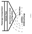
- FIG. 2 Shown in Figure 2 is an arrangement for an armored vehicle made in accordance with the present invention.
- the vehicle includes a passenger compartment that is supported on a floor.
- An armor substructure made in accordance with the present invention is mounted beneath the vehicle floor.
- the armor substructure provides a blast resistant barrier to protect the passenger compartment from the effects of an exploding IED or mine. Buildings and architectural features such as doors can also be fitted with armor articles in accordance with this invention. It is also contemplated that the armor articles of this invention can be used in luggage, storage containers and containment trashcans for nuclear waste and other types of hazardous waste that may be transported on public roads or rail lines.
- Heat 1 was ARC-AOD melted whereas Heat 2 was ARC-ESR melted.
- the objective of this example was to produce plate material in accordance with the first process described above.
- Material from the ingot of Heat 1 and from the ingot of Heat 2 was hot worked to provide slabs 2.58 inches (6.55 cm) thick.
- the slab formed from Heat 1 was heated to a temperature of 1650°F (899°C) and hot rolled to 0.55 inch (13.97 mm) thick plate.
- the slab formed from Heat 2 was heated to a temperature of 1650°F (899°C) and hot rolled to 0.53 inch (13.5 mm) thick plate.
- the plate material was quenched with water within about 10 minutes of the last rolling pass.
- the objective of this example was to produce plate material using the two-step process described above. Additional material from the ingot of Heat 2 was hot worked to provide slabs nominally 5 inches (12.7 cm) thick. The slabs were then hot rolled to intermediate thicknesses. A first slab was hot rolled from a start temperature of about 2100°F (1149°C) to an intermediate thickness of about 0.72 inches (18.3 mm). A second slab was rolled from a start temperature of about 2100°F (1149°C) to an intermediate thickness of about 0.905 inches (23 mm). A third slab was rolled from a start temperature of about 2100°F (1149°C) to an intermediate thickness of about 1.25 inches (31.75 mm).
- a fourth slab was rolled from a start temperature of about 2100°F (1149°C) to an intermediate thickness of about 2.55 inches (6.48 cm).
- the intermediate forms were rapidly cooled with water within about 5 minutes of completion of the last rolling pass on each intermediate slab.
- the slabs were annealed at a temperature of about 1832°F (1000°C) for about 30 minutes per inch of thickness and then water cooled.
- the annealed intermediate forms were then warm worked from a start temperature of about 800°F to about 1200°F (426.7°C to 649°C) to impart RIT's ranging from about 15% to about 85%. More specifically, the 0.72-inch (18.3 mm) thick slab was warm worked from a temperature of about 1100 °F (593°C) to a thickness of about 0.55 inches (13.97 mm) representing an RIT of about 24%. The 0.905-inch (23 mm) thick slab was warm worked from a temperature of about 1100 °F (593°C) to a thickness of about 0.55 inches (13.97 mm) representing an RIT of about 41 %.
- the 1.25-inch (31.75 mm) thick slab was warm worked from a temperature of about 1100 °F (593°C) to a thickness of about 0.55 inches (13.97 mm) representing an RIT of about 56%.
- the 2.55-inch (6.48 cm) thick slab was warm worked from a temperature of about 1100 °F (593°C) to a thickness of about 0.55 inches (13.97 mm) representing an RIT of about 78%.
- the hot rolled plates were cooled in air.
- an armor article made in accordance with the present invention makes the armor highly resistant to both armor piercing projectiles and blast fragments such as from IED's.
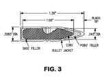
- Specimens of the armor plate produced in the examples were tested to determine the V50 velocity for both armor piercing rounds (.30 cal APM2) and fragment simulating projectiles (FSP) fired normal to the plane of the armor tested in accordance with MIL-STD-662F.
- the V50 velocity is defined as the projectile velocity at which 50% of projectiles impacting the armor will defeat the armor such as by penetration.
- a typical APM2 round used for the ballistic testing is shown in Figure 3 .
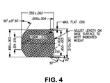
- a typical FSP projectile used for the blast resistance testing is shown in Figure 4 .
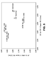
- the combination of .50 Cal FSP V50 and .30 Cal APM2 V50 provided by 0.55-inch thick armor plate samples prepared in accordance with the present invention is shown in Figure 5 .
- the data points are for samples having different combinations of melting technique, annealing temperature, and percent RIT as described above. Data points near the upper right hand corner of the graph represent the best combination of APM2 and FSP V50 velocities.
Abstract
An article of manufacture formed of an alloy having the following weight percent composition is described.
Carbon 0.25 max.
Manganese 14-20
Silicon up to 2.0
Phosphorus 0.05 max.
Sulfur 0.5 max.
Chromium 12-22
Nickel 3.5 max.
Molybdenum 0.5-4
Copper 2.0 max.
Nitrogen 0.2-0.8
Boron 0.06 max.
The balance of the alloy is iron and the usual, inevitable impurities found in commercial grades of stainless steel alloys. Optionally, the alloy may contain niobium, titanium, vanadium, zirconium, hafnium, and tungsten in a combined amount of up to about 0.5%. An intermediate form of the article is armor plate made from the alloy. In accordance with another aspect of the present invention, the plate is shaped to form an armor part that is attached to a larger structure to provide resistance to an explosion fragments or a ballistic projectile.
Description
- This invention relates to blast resistant articles of manufacture and in particular to such an armor article made from a corrosion resistant, non-magnetic, high strength, high toughness steel alloy and to a process for making the armor article.
- The use of improvised explosive devices (IED's) and land mines by military insurgents causes significant destruction of military equipment and substantial injury and loss of life of military personnel. Because of such threats, a need has arisen among armored vehicle manufacturers for new blast-resistant materials which provide a better combination of strength with energy absorption capability than the materials currently in use. Energy absorption capability is related to the toughness of a material. The toughness of a material has been defined as the ability to absorb energy and deform plastically before fracturing. Two known families of materials used for blast resistant armor are martensitic steels and aluminum alloys. Martensitic steels provide high strength, but less than desirable energy absorption compared to aluminum alloys. On the other hand, aluminum alloys provide good energy absorption, but lower strength than martensitic steels. It is also desirable for the blast resistant material to be non-magnetic so that it would provide some protection from mines that are magnetically triggered.
- Austenitic stainless steel alloys sold under the registered trademarks "15-15LC" and "15-15HS" are designed for and have been used exclusively for making components for the oil-drilling industry, primarily drill collars. The alloys sold under the marks "15-15LC" and "15-15HS" are described and claimed in
U.S. Patent No. 3,904,401 ,U.S. Patent No. 5,094,812 , andU.S. Patent No. 5,308,877 . - In accordance with a first aspect of this invention there is provided a blast resistant armor article that is formed of an alloy having any of the following broad and preferred compositions in weight percent.
Broad Preferred 1 Preferred 2 Preferred 3 Carbon 0.25 max. 0.08 max. 0.05 max. 0.035 max. Manganese 14-20 14-19 15-18 16-18 Silicon up to 2.0 1 max. 1 max. 0.75 max. Phosphorus 0.05 max. 0.05 max. 0.05 max. 0.05 max. Sulfur 0.5 max. 0.03 max. 0.03 max. 0.03 max. Chromium 12-22 12-21 14-19.5 16-18 Nickel 3.5 max. 3.5 max. 2.5 max. 1.5 max. Molybdenum 0.5-4 0.5-4 0.75-2.5 1.0-2.0 Copper 2.0 max. 2.0 max. 1.5 max. 1.0 max. Nitrogen 0.2-0.8 0.2-0.8 0.3-0.7 0.4-0.6 Boron 0.06 max. 0.06 max. 0.005 max. 0.005 max. - The balance of the alloy is iron and the usual, inevitable impurities found in commercial grades of stainless steel alloys. Optionally, the alloy may contain niobium, titanium, vanadium, zirconium, hafnium, and tungsten in a combined amount of up to about 0.5%. An intermediate form of the article is plate made from the alloy. In accordance with another aspect of the present invention, the plate is shaped to form an armor part that is attached to a larger structure to provide resistance to an explosion or a ballistic projectile.
- In accordance with a further aspect of the present invention, there is provided a process for making armor plate for vehicles and other structures. The process includes the step of melting an alloy having any of the following broad and preferred weight percent compositions.
Broad Preferred 1 Preferred 2 Preferred 3 Carbon 0.25 max. 0.08 max. 0.05 max. 0.035 max. Manganese 14-20 14-19 15-18 16-18 Silicon up to 2.0 1 max. 1 max. 0.75 max. Phosphorus 0.05 max. 0.05 max. 0.05 max. 0.05 max. Sulfur 0.5 max. 0.03 max. 0.03 max. 0.03 max. Chromium 12-22 12-21 14-19.5 16-18 Nickel 3.5 max. 3.5 max. 2.5 max. 1.5 max. Molybdenum 0.5-4 0.5-4 0.75-2.5 1.0-2.0 Copper 2.0 max. 2.0 max. 1.5 max. 1.0 max. Nitrogen 0.2-0.8 0.2-0.8 0.3-0.7 0.4-0.6 Boron 0.06 max. 0.06 max. 0.005 max. 0.005 max. Iron Balance Balance Balance Balance - The "Balance" includes inevitable impurities found in commercial grades of stainless steel alloys. Optionally, the alloy may contain niobium, titanium, vanadium, zirconium, hafnium, and tungsten in a combined amount of up to about 0.5%. The alloy is hot worked to plate having a final thickness that provides a preselected level of strength and impact toughness. Alternatively, the alloy is hot worked to plate having an intermediate thickness. The intermediate thickness plate material is then preferably warm-worked to a final thickness that provides a preselected level of strength and impact toughness. The process further includes the step of shaping the warm-worked plate to form an armor part for a vehicle or other structure without annealing after the warm working step.
- The foregoing tabulations are provided as convenient summaries and are not intended thereby to restrict the lower and upper values of the ranges of the individual elements of the alloy used in this invention for use solely in combination with each other or to restrict the various broad and preferred ranges of the elements for use solely in combination with each other. Thus, one or more of the broad and preferred ranges can be used with one or more of the other ranges for the remaining elements. In addition, a broad or preferred minimum or maximum for an element can be used with the maximum or minimum for that element from one of the remaining ranges. Throughout this application, the symbol "%" or "w/o" or the term "percent" means weight percent or mass percent unless otherwise indicated.
- The foregoing summary of the invention and the following detailed description will be better understood when read in conjunction with the drawings, wherein:
-
Figure 1 is a graph of Charpy V-notch toughness as a function of hardness for alloys used in the present invention compared to the known alloys. -
Figure 2 is a schematic diagram of a passenger vehicle equipped with a blast protective armor article in accordance with the present invention. -
Figure 3 is a schematic diagram of a .30 Cal armor piercing projectile. -
Figure 4 is a schematic diagram of a .50 Cal fragment simulating projectile. -
Figure 5 is a graph of .30 Cal APM2 V50 velocity as a function of the .50 Cal FSP V50 velocity for examples of armor plate made in accordance with the present invention. - An armor article according to this invention includes a shaped piece of steel plate. The steel plate is made from a high strength, corrosion resistant alloy have a weight percent composition that is within any of the broad or preferred weight percent ranges described above. The alloy used in the article according to the present invention provides substantial resistance to damage from explosions because it provides a unique combination of very high strength and high toughness. The toughness property is one measure of damage tolerance for armor material. The toughness of a material is typically evaluated based on the Charpy V-notch impact strength (CVN). CVN is determined in accordance with ASTM Standard Test Specification E 23. The hardness of a material is a measure of its strength. The harder a material is, the higher its strength is expected to be. Set forth in
Figure 1 is a graph showing the CVN of certain alloys as a function of the hardness of the material. - The 15-15 LC Alloy and the 15-15 HS Alloy are alloys whose weight percent compositions are within the scope of the alloys used in the present invention as described in the Broad and Preferred ranges set forth above. Referring to
Figure 1 , it is clear that the alloys used in the present invention provide significantly greater impact toughness than very high strength steels such asAISI 4340 andAISI 4130 which have variants that are currently used for armor applications. It is also seen fromFigure 1 , that the 15-15 LC alloy and the 15-15 HS alloy provide high strength in the unannealed condition that is at least as good as the very highstrength alloys AISI 4340 andAISI 4130. The combinations of hardness and toughness illustrated inFigure 1 for the 15-15 LC alloy and for the 15-15 HS alloy are clearly superior to the combinations of those properties demonstrated for theAISI 4340 andAISI 4130 alloys. Moreover, the 15-15 LC alloy is nonmagnetic and so cannot set off a magnetically activated land mine or IED. - The alloys used in an article according to this invention are readily prepared by means of conventional, well-known techniques including powder metallurgy. Cast and wrought forms of the alloys are initially melted by electric arc melting (ARC) preferably followed by argon-oxygen decarburization (AOD) and cast as an electrode or as an ingot. In addition, the electrodes of this alloy may be further refined by electroslag remelting (ESR). After final melting is complete, the ingot is preferably homogenized and then formed into plate of a desired thickness. In this regard, the ARC or ESR ingot is initially hot worked to form an elongated slab. The slab is then further processed in either of two ways. In a first process, the slab is hot worked, preferably by rolling, pressing, or forging the slab until a plate having a desired thickness is obtained. The final thickness is selected such that the alloy receives a reduction in thickness (RIT) that is sufficient to provide a desired combination of strength, hardness, and toughness in the alloy plate. In the first process, the slab is preferably hot rolled to plate from a temperature of about 1500°F-2000°F (about 816°C-1093°C) down to a finish temperature of about 1100°F-1400°F (about 593°C-760°C). Preferably, the plate is rapidly cooled from the finish temperature such as by quenching with water or oil. The cooling should be conducted quickly after completion of the hot rolling to avoid further sensitization of the alloy. However, the inventors have determined that some sensitization of the alloy may be beneficial to the ballistic properties of the armor applications. The hot rolling step can be conducted in one or more passes with reheating as necessary if the finish temperature is reached before the desired thickness is obtained.
- In the second process, the slab is hot worked, again preferably by rolling, pressing, or forging the slab to an elongated plate having an intermediate thickness. The hot working step is preferably conducted from a start temperature of about 1700°F-2200°F (about 927°C-1204°C) down to a finish temperature of about 1600°F-1900°F (about 871°C-1038°C). Preferably, the intermediate thickness plate is rapidly cooled as above, preferably within minutes after completion of the hot rolling step in order to avoid sensitization of the alloy. The intermediate thickness plate material is preferably annealed at about 1600°F-2350°F (about 871°C-1288°C) for about 30 minutes per inch of thickness and then water cooled to room temperature. The annealed intermediate plate is then warm-worked, again preferably by rolling, pressing, or forging, at a temperature of about 800°F-1200°F (about 427°C-649°C) to an RIT that is sufficient to provide the desired combination of strength and toughness in the as-worked material. The warm-worked plate is quenched, as in water, but is not subsequently annealed. The amount of warm working applied to the alloy, i.e., the percent RIT, is selected based on the level of hardness and strength to be provided by the armor article. The greater the RIT is the greater will be the strength and toughness of the alloy plate. It is anticipated that the plate material produced in accordance with this invention will provide a Brinell hardness (BHN) of about 275-400.
- After the plate material is formed, it is cut into parts which are shaped by bending operations, for example. The shaped parts are then machined as necessary and attached to a vehicle or other object by any known technique such as by welding or with fasteners such as bolts, screws, or rivets. Armor articles made in accordance the present invention, exhibit an outstanding combination of properties including very high strength and toughness, good corrosion resistance, and good non-magnetic behavior. It is contemplated that armor articles made in accordance with this invention can be used in or on a wide variety of vehicles and other objects for which blast resistance/tolerance is needed. Military vehicles such as tanks, trucks, personnel carriers, aircraft, ships, and submarines are all suitable candidates for receiving armor articles made according to the invention. In addition, civilian security vehicles would also benefit from the use of armor articles according to the invention. Shown in
Figure 2 is an arrangement for an armored vehicle made in accordance with the present invention. The vehicle includes a passenger compartment that is supported on a floor. An armor substructure made in accordance with the present invention is mounted beneath the vehicle floor. The armor substructure provides a blast resistant barrier to protect the passenger compartment from the effects of an exploding IED or mine. Buildings and architectural features such as doors can also be fitted with armor articles in accordance with this invention. It is also contemplated that the armor articles of this invention can be used in luggage, storage containers and containment trashcans for nuclear waste and other types of hazardous waste that may be transported on public roads or rail lines. - In order to demonstrate the process and product of the present invention, two heats were melted and processed into plate. The plate material was then tested to determine the relevant mechanical properties, ballistic tolerance, and blast resistance of the as-processed material. The weight percent compositions of the two heats are set forth in Table 1 below.
TABLE 1 Element Heat 1 Heat 2 C 0.035 0.027 Mn 17.99 18.41 Si 0.36 0.37 P 0.022 0.028 S 0.001 <0.001 Cr 17.66 18.56 Ni 0.94 1.97 Mo 0.77 0.74 Cu 0.06 0.06 N 0.52 0.57 B 0.0019 0.0024 - The balance of each heat is iron and usual impurities. Heat 1 was ARC-AOD melted whereas Heat 2 was ARC-ESR melted.
- The objective of this example was to produce plate material in accordance with the first process described above. Material from the ingot of Heat 1 and from the ingot of Heat 2 was hot worked to provide slabs 2.58 inches (6.55 cm) thick. The slab formed from Heat 1 was heated to a temperature of 1650°F (899°C) and hot rolled to 0.55 inch (13.97 mm) thick plate. The slab formed from Heat 2 was heated to a temperature of 1650°F (899°C) and hot rolled to 0.53 inch (13.5 mm) thick plate. For both heats, the plate material was quenched with water within about 10 minutes of the last rolling pass. Longitudinal and transverse samples for hardness, tensile, and toughness testing were cut from the plates and machined to form standard size test specimens. The results of room temperature hardness, tensile, and Charpy V-notch toughness testing are shown in Tables 2A and 2B below including the Brinell hardness number (BHN), the 0.2% offset yield strength (YS) and ultimate tensile strength (UTS) in ksi, the percent elongation (%El.), the percent reduction in area (%R.A.), and the Charpy V-notch impact strength in foot-pounds (ft-lbs). The value for BHN is the average of five (5) different readings. The CVN values are presented as the average of four (4) tests.
TABLE 2A Longitudinal BHN Y.S. U.T.S. %El. %R.A. CVN Heat 1 339 142.3 157.6 34 60 38.3 Heat 2 353 149.9 165.2 34 63 62.7 TABLE 2B Transverse BHN Y.S. U.T.S. %El. %R.A. CVN Heat 1 339 130.7 151.3 34 63 43.5 Heat 2 353 143 160.4 31 60 40.7 - The objective of this example was to produce plate material using the two-step process described above. Additional material from the ingot of Heat 2 was hot worked to provide slabs nominally 5 inches (12.7 cm) thick. The slabs were then hot rolled to intermediate thicknesses. A first slab was hot rolled from a start temperature of about 2100°F (1149°C) to an intermediate thickness of about 0.72 inches (18.3 mm). A second slab was rolled from a start temperature of about 2100°F (1149°C) to an intermediate thickness of about 0.905 inches (23 mm). A third slab was rolled from a start temperature of about 2100°F (1149°C) to an intermediate thickness of about 1.25 inches (31.75 mm). A fourth slab was rolled from a start temperature of about 2100°F (1149°C) to an intermediate thickness of about 2.55 inches (6.48 cm). The intermediate forms were rapidly cooled with water within about 5 minutes of completion of the last rolling pass on each intermediate slab. After the intermediate hot rolling, the slabs were annealed at a temperature of about 1832°F (1000°C) for about 30 minutes per inch of thickness and then water cooled.
- The annealed intermediate forms were then warm worked from a start temperature of about 800°F to about 1200°F (426.7°C to 649°C) to impart RIT's ranging from about 15% to about 85%. More specifically, the 0.72-inch (18.3 mm) thick slab was warm worked from a temperature of about 1100 °F (593°C) to a thickness of about 0.55 inches (13.97 mm) representing an RIT of about 24%. The 0.905-inch (23 mm) thick slab was warm worked from a temperature of about 1100 °F (593°C) to a thickness of about 0.55 inches (13.97 mm) representing an RIT of about 41 %. The 1.25-inch (31.75 mm) thick slab was warm worked from a temperature of about 1100 °F (593°C) to a thickness of about 0.55 inches (13.97 mm) representing an RIT of about 56%. The 2.55-inch (6.48 cm) thick slab was warm worked from a temperature of about 1100 °F (593°C) to a thickness of about 0.55 inches (13.97 mm) representing an RIT of about 78%. The hot rolled plates were cooled in air.
- Longitudinal and transverse samples for hardness, tensile, and toughness testing were cut from the plates and machined to form standard size test specimens. The results of room temperature hardness, tensile, and Charpy V-notch toughness testing are shown in Tables 3A and 3B below including the Brinell hardness number (BHN), the 0.2% offset yield strength (YS) and the ultimate tensile strength (UTS) in ksi, the percent elongation (%El.), and the Charpy V-notch impact strength in foot-pounds (ft-lbs). The value for BHN is the average of five (5) different readings. The CVN values are presented as the average of three (3) tests.
TABLE 3A Longitudinal RIT BHN Y.S. U.T.S. %El. CVN 24% 351 125.7 160.1 38 131 41% 373 146.7 176.2 33 120.3 56% 406 167.9 188.4 28 48.7 78% 419 165 198.1 27 18 TABLE 3B Transverse RIT BHN Y.S. U.T.S. %El. CVN 24% 351 149.4 164.3 39 42.3 41% 373 143.8 175.6 33 33.0 56% 406 152.3 185.3 29 27.3 78% 419 163 195.9 27 16.7 - The combination of hardness, strength, and toughness provided by an armor article made in accordance with the present invention makes the armor highly resistant to both armor piercing projectiles and blast fragments such as from IED's. Specimens of the armor plate produced in the examples were tested to determine the V50 velocity for both armor piercing rounds (.30 cal APM2) and fragment simulating projectiles (FSP) fired normal to the plane of the armor tested in accordance with MIL-STD-662F. The V50 velocity is defined as the projectile velocity at which 50% of projectiles impacting the armor will defeat the armor such as by penetration. A typical APM2 round used for the ballistic testing is shown in
Figure 3 . A typical FSP projectile used for the blast resistance testing is shown inFigure 4 . The combination of .50 Cal FSP V50 and .30 Cal APM2 V50 provided by 0.55-inch thick armor plate samples prepared in accordance with the present invention is shown inFigure 5 . The data points are for samples having different combinations of melting technique, annealing temperature, and percent RIT as described above. Data points near the upper right hand corner of the graph represent the best combination of APM2 and FSP V50 velocities. - It will be recognized by those skilled in the art that changes or modifications may be made to the above-described embodiments without departing from the broad inventive concepts of the invention. It is understood, therefore, that the invention is not limited to the particular embodiments that are described.
Claims (15)
- A blast resistant armor article formed of a high strength, high toughness, stainless steel alloy having the following composition in weight percent, about
Carbon 0.25 max. Manganese 14-20 Silicon up to 2.0 Phosphorus 0.05 max. Sulfur 0.5 max. Chromium 12-22 Nickel 3.5 max. Molybdenum 0.5-4 Copper 2.0 max. Nitrogen 0.2-0.8 Boron 0.06 max. - An armor article as claimed in Claim 1 wherein the article comprises plate made from the alloy.
- An armor article as claimed in Claim 1 wherein the article comprises plate made from the alloy and said plate is shaped to form an armor part for attachment to a larger structure to provide resistance to damage from an explosion blast, an explosion fragment, or a ballistic projectile.
- An armor article as claimed in any of Claims 1 to 3 wherein the alloy comprises the following elements in weight percent,
Carbon 0.08 max. Manganese 14-19 Silicon 1 max. Phosphorus 0.05 max. Sulfur 0.03 max. Chromium 12-21 Nickel 3.5 max. Molybdenum 0.5-4 Copper 2.0 max. Nitrogen 0.2-0.8 Boron 0.06 max. - An armor article as claimed in any of Claims 1 to 3 wherein the alloy comprises the following elements in weight percent,
Carbon 0.05 max. Manganese 15-18 Silicon 1 max. Phosphorus 0.05 max. Sulfur 0.03 max. Chromium 14-19.5 Nickel 2.5 max. Molybdenum 0.75-2.5 Copper 1.5 max. Nitrogen 0.3-0.7 Boron 0.005 max. - An armor article as claimed in any of Claims 1 to 3 wherein the alloy comprises the following elements in weight percent,
Carbon 0.035 max. Manganese 16-18 Silicon 0.75 max. Phosphorus 0.05 max. Sulfur 0.03 max. Chromium 16-18 Nickel 1.5 max. Molybdenum 1.0-2.0 Copper 1.0 max. Nitrogen 0.4-0.6 Boron 0.005 max. - A process for making an armor component comprising the steps of:melting an alloy having the following weight percent composition, about
Carbon 0.25 max. Manganese 14-20 Silicon up to 2.0 Phosphorus 0.05 max. Sulfur 0.5 max. Chromium 12-22 Nickel 3.5 max. Molybdenum 0.5-4 Copper 2.0 max. Nitrogen 0.2-0.8 Boron 0.06 max. casting the alloy into a mold to form an ingot; and thenmechanically working said alloy ingot to form plate. - The process claimed in Claim 7 wherein the step of mechanically working the alloy ingot comprises the steps of:hot working the ingot to form a slab;hot working the slab to form the plate; and thencooling the as-formed plate at a cooling rate that is fast enough to avoid substantial sensitization of the alloy; andwherein the step of hot working the slab is performed such that the alloy receives a reduction in thickness selected to provide a combination of strength, hardness, and toughness in said plate after said cooling step sufficient to resist damage from an explosion blast, an explosion fragment, or a ballistic projectile, when tested in accordance with MIL-STD-662F.
- The process claimed in Claim 8 wherein the step of hot working the slab comprises the steps of:heating the slab to a starting temperature of about 816°C-1093°C (1500-2000°F); and thenreducing the thickness of the slab from the starting temperature down to a finish temperature of about 593°C-760°C (1100-1400°F).
- The process claimed in Claim 7 wherein the step of mechanically working the alloy ingot comprises the steps of:hot working the ingot to form a slab;hot working the slab to form an intermediate thickness plate;warm working the intermediate thickness plate to provide a final thickness plate; and then cooling the warm-worked plate;wherein the step of warm working the intermediate thickness plate is performed such that the alloy receives a reduction in thickness selected to provide a combination of strength, hardness, and toughness in said final thickness plate after said cooling step sufficient to resist damage from an explosion blast, explosion fragment, or a ballistic projectile, when tested in accordance with MIL-STD-662F.
- The process claimed in Claim 10 wherein the step of hot working the slab to intermediate thickness plate comprises the steps of
heating the slab to a start temperature of about 927°C-1204°C (1700-2200°F);
reducing the thickness of the slab from the starting temperature down to a finish temperature of about 871°C-1038°C (1600-1900°F); and then
cooling the intermediate thickness plate at a cooling rate that is fast enough to avoid sensitization of the alloy. - The process claimed in Claim 11 wherein after said step of cooling the intermediate thickness plate, the alloy is annealed at about 871°C-1288°C (1600-2350°F).
- The process claimed in any one of claims 10 to 12 wherein the warm working step is carried out at a temperature of about 427°C-649°C (800-1200°F).
- The process claimed in any one of claims 10 to 13 wherein after said warm working step, the final thickness plate is cooled at a cooling rate that is fast enough to avoid substantial sensitization of the alloy.
- The process claimed in any of Claims 7 to 14 comprising the steps of forming the plate into an armor part; and then
attaching the armor part to a vehicle, a building structure, or a containment vessel.
Applications Claiming Priority (1)
| Application Number | Priority Date | Filing Date | Title |
|---|---|---|---|
| US12/967,534 US20120156085A1 (en) | 2010-12-14 | 2010-12-14 | Blast Resistant, Non-Magnetic, Stainless Steel Armor |
Publications (1)
| Publication Number | Publication Date |
|---|---|
| EP2465954A1 true EP2465954A1 (en) | 2012-06-20 |
Family
ID=44680916
Family Applications (1)
| Application Number | Title | Priority Date | Filing Date |
|---|---|---|---|
| EP11171129A Withdrawn EP2465954A1 (en) | 2010-12-14 | 2011-06-23 | Blast resistant, non-magnetic stainless steel armor |
Country Status (2)
| Country | Link |
|---|---|
| US (1) | US20120156085A1 (en) |
| EP (1) | EP2465954A1 (en) |
Cited By (7)
| Publication number | Priority date | Publication date | Assignee | Title |
|---|---|---|---|---|
| RU2493270C1 (en) * | 2012-08-31 | 2013-09-20 | Федеральное государственное автономное образовательное учреждение высшего профессионального образования "Национальный исследовательский технологический университет "МИСиС" | Manufacturing method of heterogeneous plate steel |
| CN104513933A (en) * | 2013-09-29 | 2015-04-15 | 宝钢不锈钢有限公司 | Inexpensive non-magnetic stainless steel and manufacturing method thereof |
| EP2924131A1 (en) * | 2014-03-28 | 2015-09-30 | Outokumpu Oyj | Austenitic stainless steel |
| CN105950990A (en) * | 2015-12-31 | 2016-09-21 | 洛阳神佳窑业有限公司 | Improved explosion-proof material |
| WO2017101770A1 (en) * | 2015-12-14 | 2017-06-22 | 宝山钢铁股份有限公司 | Dual-hardness clad steel plate and production method thereof |
| CN110656275A (en) * | 2019-09-10 | 2020-01-07 | 南京钢铁股份有限公司 | Production method of steel blank of low-temperature container for one-steel multi-stage use |
| CN111500942A (en) * | 2020-05-11 | 2020-08-07 | 湖南恒基粉末科技有限责任公司 | High-nitrogen-content non-magnetic stainless steel powder and preparation method thereof |
Families Citing this family (4)
| Publication number | Priority date | Publication date | Assignee | Title |
|---|---|---|---|---|
| US11434558B2 (en) | 2018-05-23 | 2022-09-06 | Manchao He | NPR non-magnetic steel material for rock bolt and production method thereof |
| CN113249653B (en) * | 2021-05-11 | 2022-02-08 | 北京理工大学 | Bullet steel for natural fragment warhead and preparation method thereof |
| CN113699468A (en) * | 2021-08-30 | 2021-11-26 | 上海海塔机械制造有限公司 | High-nitrogen steel with high and low-temperature toughness and preparation method thereof |
| CN113699453B (en) * | 2021-08-30 | 2023-03-10 | 上海海塔机械制造有限公司 | Heat-resistant high-nitrogen steel and production method thereof |
Citations (6)
| Publication number | Priority date | Publication date | Assignee | Title |
|---|---|---|---|---|
| DE728159C (en) * | 1936-10-09 | 1942-11-21 | Boehler & Co Ag Geb | Chrome-manganese-nitrogen steel |
| US3904401A (en) | 1974-03-21 | 1975-09-09 | Carpenter Technology Corp | Corrosion resistant austenitic stainless steel |
| US5094812A (en) | 1990-04-12 | 1992-03-10 | Carpenter Technology Corporation | Austenitic, non-magnetic, stainless steel alloy |
| US5308877A (en) | 1990-01-31 | 1994-05-03 | E. I. Du Pont De Nemours And Company | Resins with high surface areas and porosities |
| DE19607828A1 (en) * | 1995-04-15 | 1996-10-17 | Vsg En & Schmiedetechnik Gmbh | High strength austenitic steel |
| DE102008005803A1 (en) * | 2008-01-17 | 2009-07-23 | Technische Universität Bergakademie Freiberg | Component used for armoring vehicles and in installations and components for transporting and recovering gases at low temperature is made from a high carbon-containing austenitic cryogenic steel cast mold |
Family Cites Families (1)
| Publication number | Priority date | Publication date | Assignee | Title |
|---|---|---|---|---|
| ES2042184T3 (en) * | 1985-12-02 | 1993-12-01 | Marco Alfredo Ganser | DEVICE FOR CONTROLLING ELECTRO-HYDRAULIC FUEL INJECTORS. |
-
2010
- 2010-12-14 US US12/967,534 patent/US20120156085A1/en not_active Abandoned
-
2011
- 2011-06-23 EP EP11171129A patent/EP2465954A1/en not_active Withdrawn
Patent Citations (6)
| Publication number | Priority date | Publication date | Assignee | Title |
|---|---|---|---|---|
| DE728159C (en) * | 1936-10-09 | 1942-11-21 | Boehler & Co Ag Geb | Chrome-manganese-nitrogen steel |
| US3904401A (en) | 1974-03-21 | 1975-09-09 | Carpenter Technology Corp | Corrosion resistant austenitic stainless steel |
| US5308877A (en) | 1990-01-31 | 1994-05-03 | E. I. Du Pont De Nemours And Company | Resins with high surface areas and porosities |
| US5094812A (en) | 1990-04-12 | 1992-03-10 | Carpenter Technology Corporation | Austenitic, non-magnetic, stainless steel alloy |
| DE19607828A1 (en) * | 1995-04-15 | 1996-10-17 | Vsg En & Schmiedetechnik Gmbh | High strength austenitic steel |
| DE102008005803A1 (en) * | 2008-01-17 | 2009-07-23 | Technische Universität Bergakademie Freiberg | Component used for armoring vehicles and in installations and components for transporting and recovering gases at low temperature is made from a high carbon-containing austenitic cryogenic steel cast mold |
Cited By (12)
| Publication number | Priority date | Publication date | Assignee | Title |
|---|---|---|---|---|
| RU2493270C1 (en) * | 2012-08-31 | 2013-09-20 | Федеральное государственное автономное образовательное учреждение высшего профессионального образования "Национальный исследовательский технологический университет "МИСиС" | Manufacturing method of heterogeneous plate steel |
| CN104513933A (en) * | 2013-09-29 | 2015-04-15 | 宝钢不锈钢有限公司 | Inexpensive non-magnetic stainless steel and manufacturing method thereof |
| EP2924131A1 (en) * | 2014-03-28 | 2015-09-30 | Outokumpu Oyj | Austenitic stainless steel |
| WO2015144896A3 (en) * | 2014-03-28 | 2016-03-17 | Outokumpu Oyj | Austenitic stainless steel |
| CN106133177A (en) * | 2014-03-28 | 2016-11-16 | 奥托库姆普有限公司 | Austenitic stainless steel |
| CN106133177B (en) * | 2014-03-28 | 2018-04-27 | 奥托库姆普有限公司 | Austenitic stainless steel |
| WO2017101770A1 (en) * | 2015-12-14 | 2017-06-22 | 宝山钢铁股份有限公司 | Dual-hardness clad steel plate and production method thereof |
| US10851435B2 (en) | 2015-12-14 | 2020-12-01 | Baoshan Iron & Steel Co., Ltd. | Dual-hardness clad steel plate and production method thereof |
| CN105950990A (en) * | 2015-12-31 | 2016-09-21 | 洛阳神佳窑业有限公司 | Improved explosion-proof material |
| CN110656275A (en) * | 2019-09-10 | 2020-01-07 | 南京钢铁股份有限公司 | Production method of steel blank of low-temperature container for one-steel multi-stage use |
| CN111500942A (en) * | 2020-05-11 | 2020-08-07 | 湖南恒基粉末科技有限责任公司 | High-nitrogen-content non-magnetic stainless steel powder and preparation method thereof |
| CN111500942B (en) * | 2020-05-11 | 2021-08-10 | 湖南恒基粉末科技有限责任公司 | High-nitrogen-content non-magnetic stainless steel powder and preparation method thereof |
Also Published As
| Publication number | Publication date |
|---|---|
| US20120156085A1 (en) | 2012-06-21 |
Similar Documents
| Publication | Publication Date | Title |
|---|---|---|
| EP2465954A1 (en) | Blast resistant, non-magnetic stainless steel armor | |
| EP2118327B9 (en) | Al-mg alloy product suitable for armour plate applications | |
| US9951404B2 (en) | Methods for making high hardness, high toughness iron-base alloys | |
| US9593916B2 (en) | High hardness, high toughness iron-base alloys and methods for making same | |
| Crouch et al. | Armour steels | |
| WO2007115617A1 (en) | Al-mg alloy product suitable for armour plate applications | |
| AU2016238855A1 (en) | Air hardenable shock-resistant steel alloys, methods of making the alloys, and articles including the alloys | |
| US20120261039A1 (en) | Method for manufacturing of vehicle armor components requiring severe forming with very high bend angles with very thick gauge product of high strength heat treatable aluminum alloys | |
| JP3886881B2 (en) | High Mn austenitic steel sheet with excellent anti-elasticity | |
| JP4374350B2 (en) | High-hardness hot-rolled steel sheet excellent in weldability, workability, and high-speed impact penetration performance and method for producing the same | |
| KR20240012514A (en) | Armor elements manufactured from 7XXX-series aluminum alloy | |
| Thomas et al. | Characterization of electroslag remelted and ladle refined, electric furnace melted 4340 Steel Armor | |
| JPS621846A (en) | Defensive steel plate against broken pieces or such flying at high speed | |
| PL214816B1 (en) | Stainless steel for armour plates and method for hardening armour plates |
Legal Events
| Date | Code | Title | Description |
|---|---|---|---|
| PUAI | Public reference made under article 153(3) epc to a published international application that has entered the european phase |
Free format text: ORIGINAL CODE: 0009012 |
|
| AK | Designated contracting states |
Kind code of ref document: A1 Designated state(s): AL AT BE BG CH CY CZ DE DK EE ES FI FR GB GR HR HU IE IS IT LI LT LU LV MC MK MT NL NO PL PT RO RS SE SI SK SM TR |
|
| AX | Request for extension of the european patent |
Extension state: BA ME |
|
| STAA | Information on the status of an ep patent application or granted ep patent |
Free format text: STATUS: THE APPLICATION IS DEEMED TO BE WITHDRAWN |
|
| 18D | Application deemed to be withdrawn |
Effective date: 20121221 |