EP2474475A2 - Method and system for a refueling drogue assembly - Google Patents
Method and system for a refueling drogue assembly Download PDFInfo
- Publication number
- EP2474475A2 EP2474475A2 EP12150105A EP12150105A EP2474475A2 EP 2474475 A2 EP2474475 A2 EP 2474475A2 EP 12150105 A EP12150105 A EP 12150105A EP 12150105 A EP12150105 A EP 12150105A EP 2474475 A2 EP2474475 A2 EP 2474475A2
- Authority
- EP
- European Patent Office
- Prior art keywords
- refueling
- coupling
- drogue
- assembly
- latch
- Prior art date
- Legal status (The legal status is an assumption and is not a legal conclusion. Google has not performed a legal analysis and makes no representation as to the accuracy of the status listed.)
- Granted
Links
- 238000000034 method Methods 0.000 title claims description 34
- 230000008878 coupling Effects 0.000 claims abstract description 79
- 238000010168 coupling process Methods 0.000 claims abstract description 79
- 238000005859 coupling reaction Methods 0.000 claims abstract description 79
- 239000000523 sample Substances 0.000 claims abstract description 74
- 239000012530 fluid Substances 0.000 claims abstract description 13
- 230000000295 complement effect Effects 0.000 claims abstract description 11
- 238000004891 communication Methods 0.000 claims description 9
- 238000012544 monitoring process Methods 0.000 claims description 4
- 238000005259 measurement Methods 0.000 description 7
- 238000004590 computer program Methods 0.000 description 3
- 239000000446 fuel Substances 0.000 description 3
- 238000013459 approach Methods 0.000 description 2
- 230000033228 biological regulation Effects 0.000 description 2
- 230000000694 effects Effects 0.000 description 2
- 231100001261 hazardous Toxicity 0.000 description 2
- 230000006872 improvement Effects 0.000 description 2
- 238000004519 manufacturing process Methods 0.000 description 2
- 230000003287 optical effect Effects 0.000 description 2
- 239000013307 optical fiber Substances 0.000 description 2
- 230000006978 adaptation Effects 0.000 description 1
- 230000005540 biological transmission Effects 0.000 description 1
- 230000008859 change Effects 0.000 description 1
- 238000001514 detection method Methods 0.000 description 1
- 238000011161 development Methods 0.000 description 1
- 230000007717 exclusion Effects 0.000 description 1
- 230000006870 function Effects 0.000 description 1
- 230000005484 gravity Effects 0.000 description 1
- 230000036541 health Effects 0.000 description 1
- 238000010438 heat treatment Methods 0.000 description 1
- 238000003780 insertion Methods 0.000 description 1
- 230000037431 insertion Effects 0.000 description 1
- 230000008569 process Effects 0.000 description 1
- 238000012545 processing Methods 0.000 description 1
- 238000005086 pumping Methods 0.000 description 1
- 230000001105 regulatory effect Effects 0.000 description 1
- 230000004044 response Effects 0.000 description 1
- 239000004065 semiconductor Substances 0.000 description 1
- 238000012546 transfer Methods 0.000 description 1
Images
Classifications
-
- B—PERFORMING OPERATIONS; TRANSPORTING
- B64—AIRCRAFT; AVIATION; COSMONAUTICS
- B64D—EQUIPMENT FOR FITTING IN OR TO AIRCRAFT; FLIGHT SUITS; PARACHUTES; ARRANGEMENTS OR MOUNTING OF POWER PLANTS OR PROPULSION TRANSMISSIONS IN AIRCRAFT
- B64D39/00—Refuelling during flight
- B64D39/06—Connecting hose to aircraft; Disconnecting hose therefrom
-
- B—PERFORMING OPERATIONS; TRANSPORTING
- B64—AIRCRAFT; AVIATION; COSMONAUTICS
- B64D—EQUIPMENT FOR FITTING IN OR TO AIRCRAFT; FLIGHT SUITS; PARACHUTES; ARRANGEMENTS OR MOUNTING OF POWER PLANTS OR PROPULSION TRANSMISSIONS IN AIRCRAFT
- B64D39/00—Refuelling during flight
- B64D39/04—Adaptations of hose construction
Abstract
Description
- The field of the invention relates generally to in-flight refueling drogues, and more specifically, to a method and system for an air-refueling drogue that provides positive latch indication of a refueling probe, reduced force latching/detaching, measurement of hose tension at the drogue end instead of at the reel end, and transmission of hose tension measurement and positive latch indication to the hose reel control system.
- Current probe and drogue aerial refueling systems infer coupling of the receiver aircraft probe with the tanker aircraft drogue on the basis of measurement of a hose tension decrease when the receiver aircraft pushes on the drogue with the refueling probe. At least two known categories of prior attempts to solve the problem, both use measurements taken at the hose reel. One method uses detection of an imbalance in hydraulic pressure to infer coupling of the receiver. Another method uses a load cell to measure a change in hose tension and infer coupling. Both of these methods are subject to false indications caused by friction as well as aerodynamic and receiver aircraft induced forces that cause false inference of coupling. Such methods are used because power, including electrical, hydraulic, pneumatic power, is not available at the drogue to allow additional remote sensing to give positive indication and control of coupling. Batteries could be used, however batteries have capacity, heating, charging, and power life aspects to contend with. The other approach is to incorporate wires or optical fibers, or the like, in the aerial refueling hose. Both of these are undesirable from an operational complexity, durability, cost, and safety view.
- In one embodiment, a refueling drogue coupling system includes a coupling latch assembly incorporated into the coupling outlet wherein the coupling latch assembly includes a latch member configured to matingly engage a complementary latch-receiving member of a refueling probe. The coupling latch assembly further includes a latch member actuator operatively coupled to the latch member to permit the latch member to move from a first locked position to a second unlocked position. A probe position sensor is configured to detect a position of the refueling probe. A hose tension sensor is configured to measure a tension in a hose coupled to the coupling inlet. A drogue control system is positioned on the refueling drogue coupling system and communicatively coupled to the latch member actuator, the probe position sensor, and the hose tension sensor.
- In another embodiment, a method of operating a refueling drogue assembly includes inserting a refueling probe of a receiving aircraft into an opening of the refueling drogue assembly extending from a tanker aircraft, detecting a presence of the refueling probe in a predetermined position of the refueling drogue assembly, and engaging a latch member of the refueling drogue assembly to a complementary latch-receiving member of the refueling probe using an actuator.
- In yet another embodiment, an aerial refueling system includes a refueling drogue coupling system configured to be extended from a tanker aircraft at a distal end of a refueling hose. The refueling drogue coupling system includes a coupling latch assembly including a latch member configured to matingly engage a complementary latch-receiving member of a refueling probe, the coupling latch assembly further configured to move the latch member from a first locked position to a second unlocked position using a latch member actuator, a hose tension control subsystem positioned in the tanker aircraft and coupled to a proximal end of the refueling hose opposite the distal end, and a drogue controller wirelessly communicatively coupled to a hose tension controller positioned in the tanker aircraft.
-
-
FIGS. 1-3 show exemplary embodiments of the method and system described herein. -
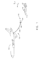
FIG. 1 is a side view of a refueling aircraft with a refueling drogue assembly deployed in accordance with an exemplary embodiment of the present invention. -
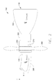
FIG. 2 is a side view of the refueling drogue assembly shown inFIG. 1 in accordance with an exemplary embodiment of the present invention. -
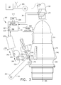
FIG. 3 is a side partially cutaway view of refuelingdrogue assembly 102 and refuelingprobe 116 in accordance with an exemplary embodiment of the present invention. - The following detailed description illustrates embodiments of the invention by way of example and not by way of limitation. The description clearly enables one skilled in the art to make and use the disclosure, describes several embodiments, adaptations, variations, alternatives, and uses of the disclosure, including what is presently believed to be the best mode of carrying out the disclosure. The disclosure is described as applied to an exemplary embodiment, namely, systems and methods of operating a drogue refueling system. However, it is contemplated that this disclosure has general application to fluid couplings in industrial, commercial, and residential applications.
- As used herein, an element or step recited in the singular and preceded with the word "a" or "an" should be understood as not excluding plural elements or steps, unless such exclusion is explicitly recited. Furthermore, references to "one embodiment" of the present invention are not intended to be interpreted as excluding the existence of additional embodiments that also incorporate the recited features.
- Embodiments of the present invention provide a positive, deterministic, means of establishing if a receiver aircraft probe is coupled with a refueling drogue in order to allow the refueling systems hose reel control system to properly initiate hose tension regulation and prevent hazardous hose whip.
- The embodiments also provide a means of positively coupling the probe and drogue at low force levels, thus allowing operations across wider airspeed and altitude envelopes. Additionally, unambiguous disconnect (due to emergency, failure, etc.) may also be commanded from either the receiver or tanker aircraft.
- Furthermore, the embodiments provide direct measurement of hose load at the drogue, thereby alleviating problems caused by attempts to infer hose load at the drogue by measuring hose load at the hose reel (via load cells or hydraulic pressure) as is common in existing systems.
- Although described as a tanker aircraft/receiver aircraft configuration where the tanker leads the receiver, as is conventional, embodiments of the present invention also permit a configuration where the receiver is in front of the tanker and the tanker follows. In this configuration the tanker pumps fuel up the hose to the receiver instead of the tanker pumping fuel down the hose to the following receiver.
-
FIG. 1 is a side view of a refuelingaircraft 100 with a refuelingdrogue assembly 102 deployed in accordance with an exemplary embodiment of the present invention. In the exemplary embodiment, refuelingdrogue assembly 102 includes a refuelingdrogue basket 104 connected to adistal portion 106 of a refuelinghose 108 that is in turn connected toaircraft 100. Ahose reel 110 and a hosetension control system 112 are positioned on refuelingaircraft 100. Hosetension control system 112 is configured to maintain forces, such as, but not limited to, aerodynamic drag, gravity, refueling probe, and dynamics, acting on refuelingdrogue assembly 102 balanced such that positional control of refuelingdrogue assembly 102 is maintained. - During a refueling operation, refueling
drogue basket 104 is unreeled from refuelingaircraft 100 towards a receiver aircraft 114 (an aircraft to be refueled), such as, but not limited to, a fighter plane or a helicopter. Arefueling probe 116 extends fromreceiver aircraft 114.Receiver aircraft 114maneuvers refueling probe 116 to refuelingdrogue basket 104 and inserts refuelingprobe 116 into a rearward facing opening 118 of refuelingdrogue basket 104, at which point a refueling coupling (not shown inFIG. 1 ) "locks" onto refuelingprobe 116, and a transfer of fuel from refuelingaircraft 100 toreceiver aircraft 114 is conducted. -
FIG. 2 is a side view of refueling drogue assembly 102 (shown inFIG. 1 ) in accordance with an exemplary embodiment of the present invention. In the exemplary embodiment, refuelingdrogue basket 104 is coupled tohose 108 through abasket collar 202 and ahose end connector 204. In various embodiments, aram air turbine 206 is used to generate electrical energy to power components of refuelingdrogue assembly 102. A gyroscopic effect ofram air turbine 206 during operation may also be used to positionally stabilize refuelingdrogue assembly 102. In various other embodiments, acable 208 may be used to carry electrical energy and/or control signals between refuelingdrogue assembly 102 andaircraft 100. In still other embodiments, refuelingdrogue assembly 102 may be powered by abattery 210 carried onboard refuelingdrogue assembly 102. -
FIG. 3 is a side partially cutaway view of refuelingdrogue assembly 102 and refuelingprobe 116 in accordance with an exemplary embodiment of the present invention. In the exemplary embodiment, refuelingdrogue assembly 102 includes adrogue controller 302 communicatively coupled to hosetension control system 112 using, in one embodiment, a wireless connection through acommunications link 304 on refuelingdrogue assembly 102 and alink 306 at hosetension control system 112.Drogue controller 302 includes aprocessor 307 and amemory 309 for executing programmed instructions that perform the processes described herein.Refueling drogue assembly 102 also includes a refuelingprobe position sensor 308 configured to detect a presence of refuelingprobe 116 in refueling drogue assembly 102 a position of refuelingprobe 116 relative to a predetermined inserted position of refuelingprobe 116 into refuelingdrogue assembly 102. Ahose tension sensor 313 is communicatively coupled to hosetension control system 112 through acommunication link 311. - A
latch assembly 310 includes alatch member 312 comprising afirst pivot end 314, alocking roller 316, and asecond pivot end 318.Latch assembly 310 also includes atoggle member 320 comprising anelongate body 322 having afirst end 324 configured to engage acam 326 pivotally coupled tolatch member actuator 328 and asecond end 330 comprising first 332 and second 334 orthogonally extending arms, saidfirst arm 332 coupled to a latchassembly bias member 336, saidsecond arm 334 coupled to saidlatch member 312.Locking roller 316 is configured to engage a complementary latch-receivingmember 338 of refuelingprobe 116. In the exemplary embodiment, latch-receivingmember 338 comprises a circumferential groove formed in aprobe collar 340 of refuelingprobe 116. - During operation, to initiate a refueling procedure,
hose 108 is played out fromreel 110 by hosetension control system 112 automatically, upon input by an operator, or in response to preprogrammed instructions. Whenhose 108 is played out to a predetermined length, receivingaircraft 114 approaches refuelingdrogue assembly 102 and inserts refuelingprobe 116 into opening 118.Latch assembly 310 is in an unlocked position such thatactuator 328 is positioned in a retracteddirection 342, which permitstoggle member 320 to rotate in aclockwise direction 344, which in turn withdrawslocking roller 316 away fromlongitudinal axis 346.Refueling probe 116 is able to be inserted using a relatively small amount of force. When refuelingprobe position sensor 308 detects the presence of refuelingprobe 116 at a predetermined position within refuelingdrogue assembly 102,drogue controller 302commands latch assembly 310 to actuate thereby positioninglocking roller 316 into engagement with latch-receivingmember 338. This procedure, usingrefueling drogue assembly 102, permits insertion ofrefueling probe 116 with relatively less force and a positive determination thatrefueling probe 116 is in a proper position for latching the lockingroller 316 onto latch-receivingmember 338. Oncerefueling probe 116 is positively engaged withrefueling drogue assembly 102,drogue controller 302 commands hosetension control system 112 to operate to control tension inhose 108. - In another embodiment, with
latch assembly 310 in a locked position, lockingroller 316 is projected towardlongitudinal axis 346 and presents an obstacle to entry ofrefueling probe 116 intorefueling drogue assembly 102. Such obstacle is overcome by using a relatively greater force that forcestoggle member 320 to work againstbias member 336 to permit lockingroller 316 to be pushed out of the path ofrefueling probe 116 by riding upinclined surface 348 ofprobe collar 340. - At the conclusion of a refueling operation or in an off normal condition either
tanker aircraft 100 orreceiver aircraft 114 may send a disengage signal todrogue controller 302 to automatically disengagerefueling probe 116 from refuelingdrogue assembly 102. During disengagement,drogue controller 302 sends a signal to latchmember actuator 328 causes latchmember actuator 328 to move to an unlock position that disengages lockingroller 316 from latch-receivingmember 338. Refuelingprobe 116 is then able to pull away from refuelingdrogue assembly 102 with a relatively small amount of disengagement force. - Embodiments of the present invention positively determine, using a sensor, such as, but not limited to, a mechanical, an optical, or a proximity detecting switch, or by using a pulse waveform detected by an accelerometer, or a combination of the above, that the refueling probe is fully latched in the drogue coupling assembly, and by measuring hose load at the drogue assembly by means of a, for example, strain gauge transducer, and then transmitting these facts and measurements via wireless data link (RF, Electro-Optical, optical fiber, etc.) to a tanker hose tension control system for the hose tension control system to begin regulating hose tension prior to development of hazardous hose whip as well as improving the quality of regulation of hose tension during tanker and receiver relative motion via direct measurement of hose load at the drogue.
- The term processor, as used herein, refers to central processing units, microprocessors, microcontrollers, reduced instruction set circuits (RISC), application specific integrated circuits (ASIC), logic circuits, and any other circuit or processor capable of executing the functions described herein.
- As used herein, the terms "software" and "firmware" are interchangeable, and include any computer program stored in memory for execution by
processor 307, including RAM memory, ROM memory, EPROM memory, EEPROM memory, and non-volatile RAM (NVRAM) memory. The above memory types are exemplary only, and are thus not limiting as to the types of memory usable for storage of a computer program. - As will be appreciated based on the foregoing specification, the above-described embodiments of the disclosure may be implemented using computer programming or engineering techniques including computer software, firmware, hardware or any combination or subset thereof, wherein the technical effect is an improvement in the safety of probe and drogue aerial refueling operations and improvements in the operational envelope (expanded ranges of altitude and airspeed) over which refueling operations can be conducted. Any such resulting program, having computer-readable code means, may be embodied or provided within one or more computer-readable media, thereby making a computer program product, i.e., an article of manufacture, according to the discussed embodiments of the disclosure. The computer-readable media may be, for example, but is not limited to, a fixed (hard) drive, diskette, optical disk, magnetic tape, semiconductor memory such as read-only memory (ROM), and/or any transmitting/receiving medium such as the Internet or other communication network or link. The article of manufacture containing the computer code may be made and/or used by executing the code directly from one medium, by copying the code from one medium to another medium, or by transmitting the code over a network.
- The above-described embodiments of a method and system of operating a drogue refueling system provides a cost-effective and reliable means ensuring a positive coupling of a refueling probe to a refueling drogue. More specifically, the method and system described herein facilitate coupling at relatively lower axial force. In addition, the above-described method and system facilitate supplying power to the drogue assembly. As a result, the method and system described herein facilitate coupling and uncoupling a refueling drogue assembly and refueling probe, directly measuring and transmitting hose load, and communicating system status and health in a cost-effective and reliable manner.
- This written description uses examples to disclose the invention, including the best mode, and also to enable any person skilled in the art to practice the invention, including making and using any devices or systems and performing any incorporated methods. The patentable scope of the invention is defined by the claims, and may include other examples that occur to those skilled in the art. Such other examples are intended to be within the scope of the claims if they have structural elements that do not differ from the literal language of the claims, or if they include equivalent structural elements with insubstantial differences from the literal languages of the claims.
- Various aspects and embodiments of the invention are indicated in the following clauses:
- 1. A refueling drogue coupling system, said system comprising:
- a fluid passage extending from a coupling inlet to a coupling outlet, said fluid passage comprising a valve seat circumscribing said fluid passage proximate said coupling outlet;
- a valve plug assembly comprising a valve plug configured to engage said seat to prevent flow through said fluid passage and an actuator assembly comprising a bias member;
- a coupling latch assembly incorporated into said coupling outlet, said coupling latch assembly comprising a latch member configured to matingly engage a complementary latch-receiving member of a refueling probe, said coupling latch assembly further comprising a latch member actuator operatively coupled to said latch member to permit said latch member to move from a first locked position to a second unlocked position;
- a probe position sensor configured to detect a position of the refueling probe;
- a hose tension sensor configured to measure a tension in a hose coupled to said coupling inlet; and
- a drogue control system positioned on said refueling drogue coupling system and communicatively coupled to said latch member actuator, said probe position sensor, and said hose tension sensor.
- 2. A system in accordance with Clause 1, further comprising a drogue power supply system positioned on said refueling drogue coupling system and configured to supply power to said refueling drogue coupling system.
- 3. A system in accordance with Clause 1, further comprising a drogue power supply system comprising at least one of a ram air turbine and a battery positioned on said refueling drogue coupling system, and a cable electrically coupled between said drogue power supply system and an offboard power supply.
- 4. A system in accordance with Clause 1, further comprising a hose tension control subsystem comprising:
- a refueling hose coupled in flow communication with said flow passage;
- a reel configured to configured to rotate about an axis to store and play out said refueling hose; and
- an actuator drivingly coupled to said reel.
- 5. A system in accordance with Clause 1, wherein said hose tension control subsystem is communicatively coupled to said drogue control system and configured to receive signals relative to hose tension from said hose tension sensor.
- 6. A system in accordance with Clause 1, wherein said coupling latch assembly comprises a toggle member comprising an elongate body having a first end configured to engage a cam pivotally coupled to said latch member actuator and a second end comprising first and second orthogonally extending arms, said first arm coupled to a latch assembly bias member, said second arm coupled to said latch member.
- 7. A system in accordance with Clause 1, wherein said coupling latch assembly is configured to lock on to the refueling probe using a first amount of axial force when said coupling latch assembly is in a said unlocked position and to lock on to the refueling probe using a second amount of axial force when said coupling latch assembly is in a said locked position, wherein said first amount of axial force is less than said second amount of axial force.
- 8. A system in accordance with Clause 7, wherein said coupling latch assembly is configured to lock on to the refueling probe using a first amount of axial force that is sufficient to overcome a force imparted by said latch assembly bias member.
- 9. A method of operating a refueling drogue assembly, said method comprising:
- inserting a refueling probe of a receiving aircraft into an opening of the refueling drogue assembly extending from a tanker aircraft;
- detecting a presence of the refueling probe in a predetermined position of the refueling drogue assembly; and
- engaging a latch member of the refueling drogue assembly to a complementary latch-receiving member of the refueling probe using an actuator.
- 10. A method in accordance with Clause 9, further comprising monitoring a tension in a refueling hose coupled in flow communication with the refueling drogue assembly.
- 11. A method in accordance with Clause 10, further comprising monitoring a tension in the refueling hose using a strain gauge.
- 12. A method in accordance with Clause 9, further comprising adjusting a tension in a refueling hose coupled in flow communication with the refueling drogue assembly based on a tension signal received from a refueling hose tension sensor.
- 13. A method in accordance with Clause 9, wherein the refueling drogue assembly includes a drogue control system positioned on the refueling drogue assembly, said method further comprising powering the refueling drogue assembly using a ram air turbine.
- 14. A method in accordance with Clause 9, further comprising:
- receiving a disengage command from at least one of the receiving aircraft and the tanker aircraft; and
- disengaging the latch member of the refueling drogue assembly using the actuator.
- 15. A method in accordance with Clause 9, further comprising supplying power to the refueling drogue assembly from a power source located on the refueling drogue assembly.
- 16. An aerial refueling system comprising:
- a refueling drogue coupling system configured to be extended from a tanker aircraft at a distal end of a refueling hose said refueling drogue coupling system comprising a coupling latch assembly comprising a latch member configured to matingly engage a complementary latch-receiving member of a refueling probe, said coupling latch assembly further configured to move said latch member to move from a first locked position to a second unlocked position using a latch member actuator;
- a hose tension control subsystem positioned in the tanker aircraft and coupled to a proximal end of the refueling hose opposite the distal end; and
- a drogue controller wirelessly communicatively coupled to a hose tension controller positioned in the tanker aircraft.
- 17. A system in accordance with Clause 16, further comprising a refueling probe position sensor configured to detect a position of a refueling probe and transmit a signal relative to the detected position to said drogue controller.
- 18. A system in accordance with Clause 16, further comprising a hose tension sensor configured to measure a tension in the refueling hose proximate the distal end and said refueling drogue coupling system.
- 19. A system in accordance with Clause 16, wherein said latch member actuator is communicatively coupled to said drogue controller.
- 20. A system in accordance with Clause 16, further comprising a drogue power supply system comprising at least one of a ram air turbine and a battery positioned on said refueling drogue coupling system, and a cable electrically coupled between said drogue power supply system and an offboard power supply.
Claims (15)
- A refueling drogue coupling system, said system comprising:a fluid passage extending from a coupling inlet to a coupling outlet, said fluid passage comprising a valve seat circumscribing said fluid passage proximate said coupling outlet;a valve plug assembly comprising a valve plug configured to engage said seat to prevent flow through said fluid passage and an actuator assembly comprising a bias member;a coupling latch assembly (310) coupled to said coupling outlet, said coupling latch assembly comprising a latch member configured to matingly engage a complementary latch-receiving member (338) of a receiver probe (116), said coupling latch assembly further comprising a latch member actuator (312) operatively coupled to said latch member to permit said latch member to move from a first locked position to a second unlocked position;a probe position sensor (308) configured to detect a position of the receiver probe;a hose tension sensor (313) configured to measure a tension in a hose coupled to said coupling inlet; anda drogue control system positioned on said refueling drogue coupling system and communicatively coupled to said latch member actuator, said probe position sensor, and said hose tension sensor.
- A system in accordance with Claim 1, further comprising a drogue power supply system positioned on said refueling drogue coupling system and configured to supply power to said refueling drogue coupling system.
- A system in accordance with Claim 1, further comprising a drogue power supply system comprising at least one of a ram air turbine (206) and a battery (210) positioned on said refueling drogue coupling system, and a cable (208) electrically coupled between said drogue power supply system and an offboard power supply.
- A system in accordance with any preceding Claim, further comprising a hose tension control subsystem (112) comprising:a refueling hose (108) coupled in flow communication with said flow passage;a reel (110) configured to configured to rotate about an axis (346) to store and play out said refueling hose; andan actuator (328) drivingly coupled to said reel.
- A system in accordance with Claim 4, wherein said hose tension control subsystem is communicatively coupled to said drogue control system and configured to receive signals relative to hose tension from said hose tension sensor (313).
- A system in accordance with any preceding Claim, wherein said coupling latch assembly (310) comprises a toggle member (320) comprising an elongate body (322) having a first end (324) configured to engage a cam (326) pivotally coupled to said latch member (328) actuator and a second end (330) comprising first and second orthogonally extending arms (332,334), said first arm coupled to a latch assembly bias member (336), said second arm coupled to said latch member.
- A system in accordance with any preceding Claim, wherein said coupling latch assembly (310) is configured to lock on to the receiver probe (116) using a first amount of axial force when said coupling latch assembly is in a said unlocked position and to lock on to the receiver probe using a second amount of axial force when said coupling latch assembly is in a said locked position, wherein said first amount of axial force is less than said second amount of axial force.
- A system in accordance with Claim 7, wherein said coupling latch assembly (310) is configured to lock on to the receiver probe (116) using a first amount of axial force that is sufficient to overcome a force imparted by said latch assembly bias member.
- An aerial refueling system (102) comprising:a refueling drogue coupling system configured to be extended from a tanker aircraft at a distal end of a refueling hose (108) said refueling drogue coupling system comprising a coupling latch assembly (310) comprising a latch member (312) configured to matingly engage a complementary latch-receiving member (338) of a receiver probe (116), said coupling latch assembly further configured to move said latch member to move from a first locked position to a second unlocked position using a latch member actuator (328);a hose tension control subsystem positioned in the tanker aircraft and coupled to a proximal end of the refueling hose opposite the distal end; anda drogue controller (302) wirelessly communicatively coupled to a hose tension controller positioned in the tanker aircraft.
- A system in accordance with Claim 9, further comprising a receiver probe (116) position sensor (308) configured to detect a position of a receiver probe and transmit a signal relative to the detected position to said drogue controller (302).
- A method of operating a refueling drogue assembly, said method comprising:inserting a refueling probe of a receiving aircraft into an opening of the refueling drogue assembly extending from a tanker aircraft;detecting a presence of the refueling probe in a predetermined position of the refueling drogue assembly; andengaging a latch member of the refueling drogue assembly to a complementary latch-receiving member of the refueling probe using an actuator.
- A method in accordance with Claim 11, further comprising monitoring a tension in a refueling hose coupled in flow communication with the refueling drogue assembly.
- A method in accordance with Claim 12, further comprising monitoring a tension in the refueling hose using a strain gauge.
- A method in accordance with any of Claims 11 to 13, further comprising adjusting a tension in a refueling hose coupled in flow communication with the refueling drogue assembly based on a tension signal received from a refueling hose tension sensor.
- A method in accordance with any of Claims 11 to 14, wherein the refueling drogue assembly includes a drogue control system positioned on the refueling drogue assembly, said method further comprising powering the refueling drogue assembly using a ram air turbine.
Applications Claiming Priority (1)
| Application Number | Priority Date | Filing Date | Title |
|---|---|---|---|
| US12/984,961 US8561947B2 (en) | 2011-01-05 | 2011-01-05 | Method and system for a refueling drogue assembly |
Publications (3)
| Publication Number | Publication Date |
|---|---|
| EP2474475A2 true EP2474475A2 (en) | 2012-07-11 |
| EP2474475A3 EP2474475A3 (en) | 2013-03-27 |
| EP2474475B1 EP2474475B1 (en) | 2016-09-07 |
Family
ID=45444545
Family Applications (1)
| Application Number | Title | Priority Date | Filing Date |
|---|---|---|---|
| EP12150105.0A Active EP2474475B1 (en) | 2011-01-05 | 2012-01-03 | Method and system for a refueling drogue assembly |
Country Status (6)
| Country | Link |
|---|---|
| US (1) | US8561947B2 (en) |
| EP (1) | EP2474475B1 (en) |
| JP (1) | JP6055181B2 (en) |
| CN (1) | CN102582839B (en) |
| BR (1) | BR102012000150A2 (en) |
| CA (1) | CA2762867C (en) |
Cited By (3)
| Publication number | Priority date | Publication date | Assignee | Title |
|---|---|---|---|---|
| EP2734446A4 (en) * | 2011-07-22 | 2015-07-22 | Carleton Life Support Sys Inc | Aerial refueling system, apparatus and methods |
| EP2952434A1 (en) * | 2014-06-03 | 2015-12-09 | Airbus Defence and Space SA | Aerial refueling coupling for in-flight operation parameter measuring |
| US11273926B2 (en) | 2019-01-24 | 2022-03-15 | Airbus Helicopters Deutschland GmbH | En route fluid transmitting apparatus |
Families Citing this family (18)
| Publication number | Priority date | Publication date | Assignee | Title |
|---|---|---|---|---|
| US9650138B2 (en) | 2012-03-30 | 2017-05-16 | W.Morrison Consulting Group, Inc. | Long range electric aircraft and method of operating same |
| WO2014011255A2 (en) * | 2012-03-30 | 2014-01-16 | W. Morrison Consulting Group, Inc. | Long range electric aircraft and method of operating same |
| US9067689B2 (en) * | 2013-01-14 | 2015-06-30 | The Boeing Company | Aircraft refueling system and method of refueling an aircraft |
| US9085370B2 (en) | 2013-06-03 | 2015-07-21 | General Electric Company | Systems and methods for wireless data transfer during in-flight refueling of an aircraft |
| CN103738502B (en) * | 2013-11-27 | 2016-02-24 | 中国航空工业集团公司西安飞机设计研究所 | A kind of Aircraft Air oil-receiving device ground check interconnecting device |
| CN103995538B (en) * | 2014-05-12 | 2017-01-11 | 中国航空工业集团公司沈阳飞机设计研究所 | Air refueling control method based on image identification |
| US9868526B2 (en) | 2014-10-15 | 2018-01-16 | W. Morrison Consulting Group, Inc. | Airborne drone delivery network and method of operating same |
| US10106274B2 (en) * | 2015-03-30 | 2018-10-23 | Sikorsky Aircraft Corporation | Tail sitter vehicle with aerial and ground refueling system |
| US9540115B2 (en) | 2015-04-28 | 2017-01-10 | Northrop Grumman Systems Corporation | Dual mode frangible refueling nozzle |
| US10053218B2 (en) | 2016-03-31 | 2018-08-21 | General Electric Company | System and method for positioning an unmanned aerial vehicle |
| US10618668B2 (en) * | 2016-09-06 | 2020-04-14 | Analytical Mechanics Associates, Inc. | Systems and apparatus for controlling movement of objects through a fluid |
| US10676189B1 (en) * | 2017-02-01 | 2020-06-09 | Lockheed Martin Corporation | Aircraft capture system and method |
| US10703501B2 (en) * | 2017-03-17 | 2020-07-07 | Analytical Mechanics Associates, Inc. | Drogue control systems and apparatus |
| GB2574078B (en) * | 2018-09-27 | 2020-05-20 | pitman James | Methods and systems for in-flight fuelling of aircraft |
| GB2590696B (en) * | 2019-12-24 | 2022-06-08 | Cobham Mission Systems Wimborne Ltd | Air-to-air coupling |
| AU2021241550A1 (en) * | 2020-03-25 | 2022-11-24 | Orbit Fab, Inc. | Material transfer interfaces for space vehicles, and associated systems and methods |
| ES2929595T3 (en) * | 2020-10-29 | 2022-11-30 | Airbus Defence & Space Sau | Active air-to-air refueling system and method for generating aerodynamic radial loads at a hose end |
| CN115924159B (en) * | 2023-03-10 | 2023-05-16 | 四川省天域航通科技有限公司 | Intelligent command control platform of large unmanned aerial vehicle and control method thereof |
Family Cites Families (32)
| Publication number | Priority date | Publication date | Assignee | Title |
|---|---|---|---|---|
| US2941761A (en) * | 1957-08-22 | 1960-06-21 | Textron Inc | Guidance system for aerial refueling |
| US3475001A (en) * | 1967-04-24 | 1969-10-28 | Schulz Tool & Mfg Co | Aerial refueling probe nozzle |
| US3586033A (en) * | 1969-07-07 | 1971-06-22 | Schulz Tool & Mfg Co | Combined aerial refueling coupling and pressure regulator |
| US3794270A (en) * | 1972-03-21 | 1974-02-26 | Electronic Communications | Method and apparatus for determining the relative attitude and position of two vehicles in space |
| US4381092A (en) * | 1981-05-01 | 1983-04-26 | Martin Marietta Corporation | Magnetic docking probe for soft docking of space vehicles |
| US4431333A (en) | 1982-04-14 | 1984-02-14 | The United States Of America As Represented By The Administrator Of The National Aeronautics And Space Administration | Apparatus for releasably connecting first and second objects in predetermined space relationship |
| US5131438A (en) * | 1990-08-20 | 1992-07-21 | E-Systems, Inc. | Method and apparatus for unmanned aircraft in flight refueling |
| US5326052A (en) * | 1991-10-02 | 1994-07-05 | Enig Associates, Inc. | Controllable hose-and-drogue in-flight refueling system |
| US5427333A (en) | 1992-10-21 | 1995-06-27 | West Coast Netting, Inc. | Variable speed drogue |
| US5255877A (en) | 1992-10-21 | 1993-10-26 | West Coast Netting, Inc. | Variable speed drogue |
| US5906336A (en) * | 1997-11-14 | 1999-05-25 | Eckstein; Donald | Method and apparatus for temporarily interconnecting an unmanned aerial vehicle |
| US6375123B1 (en) | 2000-08-15 | 2002-04-23 | The United States Of America As Represented By The Secretary Of The Navy | Air refueling drogue |
| US6604711B1 (en) * | 2000-11-20 | 2003-08-12 | Sargent Fletcher, Inc. | Autonomous system for the aerial refueling or decontamination of unmanned airborne vehicles |
| GB0106990D0 (en) * | 2001-03-21 | 2001-05-09 | Bae Systems Plc | A system for airborne launch of an aircraft from a larger carrier aircraft |
| US6926049B1 (en) * | 2002-08-23 | 2005-08-09 | Uav Refueling Inc. | Hose-and-drogue in-flight refueling system |
| US6669145B1 (en) * | 2002-12-30 | 2003-12-30 | The Boeing Company | Apparatus, method and system for fluid-motion-powered modulation of a retroreflector for remote position sensing |
| US7036770B2 (en) * | 2003-07-25 | 2006-05-02 | The Boeing Company | Methods and apparatus for illumination of refueling hoses |
| US6988693B2 (en) * | 2003-07-25 | 2006-01-24 | The Boeing Company | Methods and apparatus for passive illumination of refueling hoses |
| US6994294B2 (en) * | 2003-08-29 | 2006-02-07 | Smiths Aerospace, Inc. | Stabilization of a drogue body |
| US7185854B2 (en) * | 2004-06-18 | 2007-03-06 | The Boeing Company | In-flight refueling system and method for extending and retracting an in-flight refueling device |
| US6966525B1 (en) * | 2004-06-28 | 2005-11-22 | The Boeing Company | In-flight refueling system, alignment system, and method for automatic alignment and engagement of an in-flight refueling boom |
| US6889941B1 (en) * | 2004-07-15 | 2005-05-10 | Rockwell Collins | Aircraft formation/refueling guidance system |
| US7137598B2 (en) * | 2004-08-26 | 2006-11-21 | The Boeing Company | In-flight refueling system, sensor system and method for damping oscillations in in-flight refueling system components |
| US7007894B1 (en) * | 2004-09-21 | 2006-03-07 | The Boeing Company | In-flight refueling system, damping device and method for preventing oscillations in in-flight refueling system components |
| US20060145023A1 (en) * | 2004-12-20 | 2006-07-06 | Honeywell International, Inc. | Geometrically encoded magnetic latch intercontact face |
| US7681839B2 (en) | 2005-02-25 | 2010-03-23 | Smiths Aerospace Llc | Optical tracking system for refueling |
| US7219857B2 (en) | 2005-06-20 | 2007-05-22 | The Boeing Company | Controllable refueling drogues and associated systems and methods |
| IL170670A0 (en) | 2005-09-05 | 2006-12-31 | Israel Aerospace Ind Ltd | Drogue |
| EP1968853B1 (en) | 2005-12-22 | 2013-07-03 | GE Aviation Systems LLC | Controllable drogue |
| US8186393B2 (en) | 2008-07-24 | 2012-05-29 | Deere & Company | Fluid coupler including valve arrangement for connecting intake conduit of sprayer to transfer conduit of nurse tank during refill operation |
| US8162261B2 (en) | 2008-11-05 | 2012-04-24 | The Boeing Company | Self contained power system for controllable refueling drogues |
| GB2469635A (en) | 2009-04-20 | 2010-10-27 | Flight Refueling Ltd | Drogue adapter for a refuelling boom of an aerial refuelling apparatus |
-
2011
- 2011-01-05 US US12/984,961 patent/US8561947B2/en active Active
- 2011-12-28 JP JP2011288613A patent/JP6055181B2/en active Active
- 2011-12-29 CA CA2762867A patent/CA2762867C/en not_active Expired - Fee Related
-
2012
- 2012-01-03 EP EP12150105.0A patent/EP2474475B1/en active Active
- 2012-01-04 BR BR102012000150-0A patent/BR102012000150A2/en active Search and Examination
- 2012-01-05 CN CN201210022642.2A patent/CN102582839B/en active Active
Non-Patent Citations (1)
| Title |
|---|
| None |
Cited By (5)
| Publication number | Priority date | Publication date | Assignee | Title |
|---|---|---|---|---|
| EP2734446A4 (en) * | 2011-07-22 | 2015-07-22 | Carleton Life Support Sys Inc | Aerial refueling system, apparatus and methods |
| US11377228B2 (en) | 2011-07-22 | 2022-07-05 | Cobham Mission Systems Davenport Lss Inc. | Aerial refueling system, apparatus and methods |
| EP2952434A1 (en) * | 2014-06-03 | 2015-12-09 | Airbus Defence and Space SA | Aerial refueling coupling for in-flight operation parameter measuring |
| US9731835B2 (en) | 2014-06-03 | 2017-08-15 | Eads Construcciones Aeronáuticas, S.A. | Aerial refueling coupling for in-flight operation parameter measuring |
| US11273926B2 (en) | 2019-01-24 | 2022-03-15 | Airbus Helicopters Deutschland GmbH | En route fluid transmitting apparatus |
Also Published As
| Publication number | Publication date |
|---|---|
| US20120168564A1 (en) | 2012-07-05 |
| CN102582839A (en) | 2012-07-18 |
| EP2474475A3 (en) | 2013-03-27 |
| US8561947B2 (en) | 2013-10-22 |
| JP2012140122A (en) | 2012-07-26 |
| CN102582839B (en) | 2016-07-06 |
| CA2762867A1 (en) | 2012-07-05 |
| JP6055181B2 (en) | 2016-12-27 |
| CA2762867C (en) | 2019-02-12 |
| EP2474475B1 (en) | 2016-09-07 |
| BR102012000150A2 (en) | 2014-01-21 |
Similar Documents
| Publication | Publication Date | Title |
|---|---|---|
| US8561947B2 (en) | Method and system for a refueling drogue assembly | |
| EP2734446B1 (en) | Apparatus for an aerial refueling system | |
| EP2759478B1 (en) | Tip with nozzle load sensing and wireless communication functionality for refueling boom | |
| JP2012140122A5 (en) | ||
| US9969502B2 (en) | In-flight refueling method and system for controlling motion of the hose and drogue | |
| US10454213B2 (en) | Failure detection method in charging connector locking system | |
| BRPI1007715B1 (en) | equipment and process for refueling an aircraft with fuel | |
| US11624464B2 (en) | Device for supplying pressurized fluid, and assembly for storing pressurized fluid comprising such a device | |
| CN112218805B (en) | Apparatus and method for refueling an aircraft | |
| US20230242270A1 (en) | Air to air active refueling system and method for generating aerodynamic radial loads at a hose-end | |
| US20150284107A1 (en) | Hose&drogue in-flight refueling system with an active fuel pressure control | |
| US20200039660A1 (en) | Refuelling system | |
| EP2343240B1 (en) | System for disconnecting a fuel transfer boom. | |
| CN105417485A (en) | Intelligent gun disengagement detection device and detection method | |
| US20220018402A1 (en) | Control system and method to detect clutch slippage | |
| EP3680178B1 (en) | Air-to-air refueling (aar) hose tension control | |
| RU2780102C2 (en) | Device and methods for refueling of aircrafts | |
| KR20190058803A (en) | The method for controlling the shut-down mode of the vehicle operated by the electrical energy |
Legal Events
| Date | Code | Title | Description |
|---|---|---|---|
| PUAI | Public reference made under article 153(3) epc to a published international application that has entered the european phase |
Free format text: ORIGINAL CODE: 0009012 |
|
| AK | Designated contracting states |
Kind code of ref document: A2 Designated state(s): AL AT BE BG CH CY CZ DE DK EE ES FI FR GB GR HR HU IE IS IT LI LT LU LV MC MK MT NL NO PL PT RO RS SE SI SK SM TR |
|
| AX | Request for extension of the european patent |
Extension state: BA ME |
|
| PUAL | Search report despatched |
Free format text: ORIGINAL CODE: 0009013 |
|
| AK | Designated contracting states |
Kind code of ref document: A3 Designated state(s): AL AT BE BG CH CY CZ DE DK EE ES FI FR GB GR HR HU IE IS IT LI LT LU LV MC MK MT NL NO PL PT RO RS SE SI SK SM TR |
|
| AX | Request for extension of the european patent |
Extension state: BA ME |
|
| RIC1 | Information provided on ipc code assigned before grant |
Ipc: B64D 39/06 20060101AFI20130221BHEP |
|
| 17P | Request for examination filed |
Effective date: 20130927 |
|
| RBV | Designated contracting states (corrected) |
Designated state(s): AL AT BE BG CH CY CZ DE DK EE ES FI FR GB GR HR HU IE IS IT LI LT LU LV MC MK MT NL NO PL PT RO RS SE SI SK SM TR |
|
| GRAP | Despatch of communication of intention to grant a patent |
Free format text: ORIGINAL CODE: EPIDOSNIGR1 |
|
| INTG | Intention to grant announced |
Effective date: 20160512 |
|
| GRAS | Grant fee paid |
Free format text: ORIGINAL CODE: EPIDOSNIGR3 |
|
| GRAA | (expected) grant |
Free format text: ORIGINAL CODE: 0009210 |
|
| AK | Designated contracting states |
Kind code of ref document: B1 Designated state(s): AL AT BE BG CH CY CZ DE DK EE ES FI FR GB GR HR HU IE IS IT LI LT LU LV MC MK MT NL NO PL PT RO RS SE SI SK SM TR |
|
| REG | Reference to a national code |
Ref country code: GB Ref legal event code: FG4D |
|
| REG | Reference to a national code |
Ref country code: CH Ref legal event code: EP |
|
| REG | Reference to a national code |
Ref country code: IE Ref legal event code: FG4D |
|
| REG | Reference to a national code |
Ref country code: AT Ref legal event code: REF Ref document number: 826593 Country of ref document: AT Kind code of ref document: T Effective date: 20161015 |
|
| REG | Reference to a national code |
Ref country code: DE Ref legal event code: R096 Ref document number: 602012022534 Country of ref document: DE |
|
| REG | Reference to a national code |
Ref country code: LT Ref legal event code: MG4D |
|
| REG | Reference to a national code |
Ref country code: NL Ref legal event code: MP Effective date: 20160907 |
|
| REG | Reference to a national code |
Ref country code: FR Ref legal event code: PLFP Year of fee payment: 6 |
|
| PG25 | Lapsed in a contracting state [announced via postgrant information from national office to epo] |
Ref country code: FI Free format text: LAPSE BECAUSE OF FAILURE TO SUBMIT A TRANSLATION OF THE DESCRIPTION OR TO PAY THE FEE WITHIN THE PRESCRIBED TIME-LIMIT Effective date: 20160907 Ref country code: RS Free format text: LAPSE BECAUSE OF FAILURE TO SUBMIT A TRANSLATION OF THE DESCRIPTION OR TO PAY THE FEE WITHIN THE PRESCRIBED TIME-LIMIT Effective date: 20160907 Ref country code: NO Free format text: LAPSE BECAUSE OF FAILURE TO SUBMIT A TRANSLATION OF THE DESCRIPTION OR TO PAY THE FEE WITHIN THE PRESCRIBED TIME-LIMIT Effective date: 20161207 Ref country code: LT Free format text: LAPSE BECAUSE OF FAILURE TO SUBMIT A TRANSLATION OF THE DESCRIPTION OR TO PAY THE FEE WITHIN THE PRESCRIBED TIME-LIMIT Effective date: 20160907 Ref country code: HR Free format text: LAPSE BECAUSE OF FAILURE TO SUBMIT A TRANSLATION OF THE DESCRIPTION OR TO PAY THE FEE WITHIN THE PRESCRIBED TIME-LIMIT Effective date: 20160907 |
|
| REG | Reference to a national code |
Ref country code: AT Ref legal event code: MK05 Ref document number: 826593 Country of ref document: AT Kind code of ref document: T Effective date: 20160907 |
|
| PG25 | Lapsed in a contracting state [announced via postgrant information from national office to epo] |
Ref country code: NL Free format text: LAPSE BECAUSE OF FAILURE TO SUBMIT A TRANSLATION OF THE DESCRIPTION OR TO PAY THE FEE WITHIN THE PRESCRIBED TIME-LIMIT Effective date: 20160907 Ref country code: SE Free format text: LAPSE BECAUSE OF FAILURE TO SUBMIT A TRANSLATION OF THE DESCRIPTION OR TO PAY THE FEE WITHIN THE PRESCRIBED TIME-LIMIT Effective date: 20160907 Ref country code: GR Free format text: LAPSE BECAUSE OF FAILURE TO SUBMIT A TRANSLATION OF THE DESCRIPTION OR TO PAY THE FEE WITHIN THE PRESCRIBED TIME-LIMIT Effective date: 20161208 Ref country code: ES Free format text: LAPSE BECAUSE OF FAILURE TO SUBMIT A TRANSLATION OF THE DESCRIPTION OR TO PAY THE FEE WITHIN THE PRESCRIBED TIME-LIMIT Effective date: 20160907 Ref country code: LV Free format text: LAPSE BECAUSE OF FAILURE TO SUBMIT A TRANSLATION OF THE DESCRIPTION OR TO PAY THE FEE WITHIN THE PRESCRIBED TIME-LIMIT Effective date: 20160907 |
|
| PG25 | Lapsed in a contracting state [announced via postgrant information from national office to epo] |
Ref country code: EE Free format text: LAPSE BECAUSE OF FAILURE TO SUBMIT A TRANSLATION OF THE DESCRIPTION OR TO PAY THE FEE WITHIN THE PRESCRIBED TIME-LIMIT Effective date: 20160907 Ref country code: RO Free format text: LAPSE BECAUSE OF FAILURE TO SUBMIT A TRANSLATION OF THE DESCRIPTION OR TO PAY THE FEE WITHIN THE PRESCRIBED TIME-LIMIT Effective date: 20160907 |
|
| PG25 | Lapsed in a contracting state [announced via postgrant information from national office to epo] |
Ref country code: CZ Free format text: LAPSE BECAUSE OF FAILURE TO SUBMIT A TRANSLATION OF THE DESCRIPTION OR TO PAY THE FEE WITHIN THE PRESCRIBED TIME-LIMIT Effective date: 20160907 Ref country code: SM Free format text: LAPSE BECAUSE OF FAILURE TO SUBMIT A TRANSLATION OF THE DESCRIPTION OR TO PAY THE FEE WITHIN THE PRESCRIBED TIME-LIMIT Effective date: 20160907 Ref country code: BG Free format text: LAPSE BECAUSE OF FAILURE TO SUBMIT A TRANSLATION OF THE DESCRIPTION OR TO PAY THE FEE WITHIN THE PRESCRIBED TIME-LIMIT Effective date: 20161207 Ref country code: PL Free format text: LAPSE BECAUSE OF FAILURE TO SUBMIT A TRANSLATION OF THE DESCRIPTION OR TO PAY THE FEE WITHIN THE PRESCRIBED TIME-LIMIT Effective date: 20160907 Ref country code: AT Free format text: LAPSE BECAUSE OF FAILURE TO SUBMIT A TRANSLATION OF THE DESCRIPTION OR TO PAY THE FEE WITHIN THE PRESCRIBED TIME-LIMIT Effective date: 20160907 Ref country code: SK Free format text: LAPSE BECAUSE OF FAILURE TO SUBMIT A TRANSLATION OF THE DESCRIPTION OR TO PAY THE FEE WITHIN THE PRESCRIBED TIME-LIMIT Effective date: 20160907 Ref country code: PT Free format text: LAPSE BECAUSE OF FAILURE TO SUBMIT A TRANSLATION OF THE DESCRIPTION OR TO PAY THE FEE WITHIN THE PRESCRIBED TIME-LIMIT Effective date: 20170109 Ref country code: IS Free format text: LAPSE BECAUSE OF FAILURE TO SUBMIT A TRANSLATION OF THE DESCRIPTION OR TO PAY THE FEE WITHIN THE PRESCRIBED TIME-LIMIT Effective date: 20170107 Ref country code: BE Free format text: LAPSE BECAUSE OF FAILURE TO SUBMIT A TRANSLATION OF THE DESCRIPTION OR TO PAY THE FEE WITHIN THE PRESCRIBED TIME-LIMIT Effective date: 20160907 |
|
| REG | Reference to a national code |
Ref country code: DE Ref legal event code: R097 Ref document number: 602012022534 Country of ref document: DE |
|
| PG25 | Lapsed in a contracting state [announced via postgrant information from national office to epo] |
Ref country code: IT Free format text: LAPSE BECAUSE OF FAILURE TO SUBMIT A TRANSLATION OF THE DESCRIPTION OR TO PAY THE FEE WITHIN THE PRESCRIBED TIME-LIMIT Effective date: 20160907 |
|
| PLBE | No opposition filed within time limit |
Free format text: ORIGINAL CODE: 0009261 |
|
| STAA | Information on the status of an ep patent application or granted ep patent |
Free format text: STATUS: NO OPPOSITION FILED WITHIN TIME LIMIT |
|
| PG25 | Lapsed in a contracting state [announced via postgrant information from national office to epo] |
Ref country code: DK Free format text: LAPSE BECAUSE OF FAILURE TO SUBMIT A TRANSLATION OF THE DESCRIPTION OR TO PAY THE FEE WITHIN THE PRESCRIBED TIME-LIMIT Effective date: 20160907 |
|
| 26N | No opposition filed |
Effective date: 20170608 |
|
| PG25 | Lapsed in a contracting state [announced via postgrant information from national office to epo] |
Ref country code: SI Free format text: LAPSE BECAUSE OF FAILURE TO SUBMIT A TRANSLATION OF THE DESCRIPTION OR TO PAY THE FEE WITHIN THE PRESCRIBED TIME-LIMIT Effective date: 20160907 |
|
| REG | Reference to a national code |
Ref country code: CH Ref legal event code: PL |
|
| PG25 | Lapsed in a contracting state [announced via postgrant information from national office to epo] |
Ref country code: MC Free format text: LAPSE BECAUSE OF FAILURE TO SUBMIT A TRANSLATION OF THE DESCRIPTION OR TO PAY THE FEE WITHIN THE PRESCRIBED TIME-LIMIT Effective date: 20160907 |
|
| PG25 | Lapsed in a contracting state [announced via postgrant information from national office to epo] |
Ref country code: LI Free format text: LAPSE BECAUSE OF NON-PAYMENT OF DUE FEES Effective date: 20170131 Ref country code: CH Free format text: LAPSE BECAUSE OF NON-PAYMENT OF DUE FEES Effective date: 20170131 |
|
| REG | Reference to a national code |
Ref country code: IE Ref legal event code: MM4A |
|
| PG25 | Lapsed in a contracting state [announced via postgrant information from national office to epo] |
Ref country code: LU Free format text: LAPSE BECAUSE OF NON-PAYMENT OF DUE FEES Effective date: 20170103 |
|
| REG | Reference to a national code |
Ref country code: FR Ref legal event code: PLFP Year of fee payment: 7 |
|
| PG25 | Lapsed in a contracting state [announced via postgrant information from national office to epo] |
Ref country code: IE Free format text: LAPSE BECAUSE OF NON-PAYMENT OF DUE FEES Effective date: 20170103 |
|
| PG25 | Lapsed in a contracting state [announced via postgrant information from national office to epo] |
Ref country code: MT Free format text: LAPSE BECAUSE OF NON-PAYMENT OF DUE FEES Effective date: 20170103 |
|
| PG25 | Lapsed in a contracting state [announced via postgrant information from national office to epo] |
Ref country code: AL Free format text: LAPSE BECAUSE OF FAILURE TO SUBMIT A TRANSLATION OF THE DESCRIPTION OR TO PAY THE FEE WITHIN THE PRESCRIBED TIME-LIMIT Effective date: 20160907 |
|
| PG25 | Lapsed in a contracting state [announced via postgrant information from national office to epo] |
Ref country code: HU Free format text: LAPSE BECAUSE OF FAILURE TO SUBMIT A TRANSLATION OF THE DESCRIPTION OR TO PAY THE FEE WITHIN THE PRESCRIBED TIME-LIMIT; INVALID AB INITIO Effective date: 20120103 |
|
| PG25 | Lapsed in a contracting state [announced via postgrant information from national office to epo] |
Ref country code: CY Free format text: LAPSE BECAUSE OF NON-PAYMENT OF DUE FEES Effective date: 20160907 |
|
| PG25 | Lapsed in a contracting state [announced via postgrant information from national office to epo] |
Ref country code: MK Free format text: LAPSE BECAUSE OF FAILURE TO SUBMIT A TRANSLATION OF THE DESCRIPTION OR TO PAY THE FEE WITHIN THE PRESCRIBED TIME-LIMIT Effective date: 20160907 |
|
| PG25 | Lapsed in a contracting state [announced via postgrant information from national office to epo] |
Ref country code: TR Free format text: LAPSE BECAUSE OF FAILURE TO SUBMIT A TRANSLATION OF THE DESCRIPTION OR TO PAY THE FEE WITHIN THE PRESCRIBED TIME-LIMIT Effective date: 20160907 |
|
| PGFP | Annual fee paid to national office [announced via postgrant information from national office to epo] |
Ref country code: DE Payment date: 20221220 Year of fee payment: 12 |
|
| P01 | Opt-out of the competence of the unified patent court (upc) registered |
Effective date: 20230414 |
|
| PGFP | Annual fee paid to national office [announced via postgrant information from national office to epo] |
Ref country code: GB Payment date: 20231219 Year of fee payment: 13 |
|
| PGFP | Annual fee paid to national office [announced via postgrant information from national office to epo] |
Ref country code: FR Payment date: 20231219 Year of fee payment: 13 |