EP2476389A1 - Treatment device for electrosurgery - Google Patents
Treatment device for electrosurgery Download PDFInfo
- Publication number
- EP2476389A1 EP2476389A1 EP10844700A EP10844700A EP2476389A1 EP 2476389 A1 EP2476389 A1 EP 2476389A1 EP 10844700 A EP10844700 A EP 10844700A EP 10844700 A EP10844700 A EP 10844700A EP 2476389 A1 EP2476389 A1 EP 2476389A1
- Authority
- EP
- European Patent Office
- Prior art keywords
- electrode
- treatment device
- distal end
- sheath
- electrosurgery
- Prior art date
- Legal status (The legal status is an assumption and is not a legal conclusion. Google has not performed a legal analysis and makes no representation as to the accuracy of the status listed.)
- Granted
Links
- 239000012212 insulator Substances 0.000 claims abstract description 40
- 230000007423 decrease Effects 0.000 claims description 3
- 210000001519 tissue Anatomy 0.000 description 61
- 238000003780 insertion Methods 0.000 description 11
- 230000037431 insertion Effects 0.000 description 11
- 238000000034 method Methods 0.000 description 11
- 208000037062 Polyps Diseases 0.000 description 8
- 238000009413 insulation Methods 0.000 description 6
- 239000000463 material Substances 0.000 description 3
- 229910001220 stainless steel Inorganic materials 0.000 description 3
- 239000010935 stainless steel Substances 0.000 description 3
- PXHVJJICTQNCMI-UHFFFAOYSA-N Nickel Chemical compound [Ni] PXHVJJICTQNCMI-UHFFFAOYSA-N 0.000 description 2
- 239000011162 core material Substances 0.000 description 2
- 230000000694 effects Effects 0.000 description 2
- 230000003287 optical effect Effects 0.000 description 2
- 238000003466 welding Methods 0.000 description 2
- BQCADISMDOOEFD-UHFFFAOYSA-N Silver Chemical compound [Ag] BQCADISMDOOEFD-UHFFFAOYSA-N 0.000 description 1
- 239000000919 ceramic Substances 0.000 description 1
- 239000012141 concentrate Substances 0.000 description 1
- 230000005489 elastic deformation Effects 0.000 description 1
- 238000010292 electrical insulation Methods 0.000 description 1
- PCHJSUWPFVWCPO-UHFFFAOYSA-N gold Chemical compound [Au] PCHJSUWPFVWCPO-UHFFFAOYSA-N 0.000 description 1
- 229910052737 gold Inorganic materials 0.000 description 1
- 239000010931 gold Substances 0.000 description 1
- 239000011810 insulating material Substances 0.000 description 1
- 229910052759 nickel Inorganic materials 0.000 description 1
- 238000002203 pretreatment Methods 0.000 description 1
- 239000011347 resin Substances 0.000 description 1
- 229920005989 resin Polymers 0.000 description 1
- 229910052709 silver Inorganic materials 0.000 description 1
- 239000004332 silver Substances 0.000 description 1
- 210000004872 soft tissue Anatomy 0.000 description 1
- 238000001356 surgical procedure Methods 0.000 description 1
Images


Classifications
-
- A—HUMAN NECESSITIES
- A61—MEDICAL OR VETERINARY SCIENCE; HYGIENE
- A61B—DIAGNOSIS; SURGERY; IDENTIFICATION
- A61B18/00—Surgical instruments, devices or methods for transferring non-mechanical forms of energy to or from the body
- A61B18/04—Surgical instruments, devices or methods for transferring non-mechanical forms of energy to or from the body by heating
- A61B18/12—Surgical instruments, devices or methods for transferring non-mechanical forms of energy to or from the body by heating by passing a current through the tissue to be heated, e.g. high-frequency current
- A61B18/14—Probes or electrodes therefor
- A61B18/1492—Probes or electrodes therefor having a flexible, catheter-like structure, e.g. for heart ablation
-
- A—HUMAN NECESSITIES
- A61—MEDICAL OR VETERINARY SCIENCE; HYGIENE
- A61B—DIAGNOSIS; SURGERY; IDENTIFICATION
- A61B18/00—Surgical instruments, devices or methods for transferring non-mechanical forms of energy to or from the body
- A61B18/04—Surgical instruments, devices or methods for transferring non-mechanical forms of energy to or from the body by heating
- A61B18/12—Surgical instruments, devices or methods for transferring non-mechanical forms of energy to or from the body by heating by passing a current through the tissue to be heated, e.g. high-frequency current
- A61B18/14—Probes or electrodes therefor
- A61B18/1442—Probes having pivoting end effectors, e.g. forceps
- A61B18/1445—Probes having pivoting end effectors, e.g. forceps at the distal end of a shaft, e.g. forceps or scissors at the end of a rigid rod
-
- A—HUMAN NECESSITIES
- A61—MEDICAL OR VETERINARY SCIENCE; HYGIENE
- A61B—DIAGNOSIS; SURGERY; IDENTIFICATION
- A61B18/00—Surgical instruments, devices or methods for transferring non-mechanical forms of energy to or from the body
- A61B2018/00571—Surgical instruments, devices or methods for transferring non-mechanical forms of energy to or from the body for achieving a particular surgical effect
- A61B2018/00595—Cauterization
-
- A—HUMAN NECESSITIES
- A61—MEDICAL OR VETERINARY SCIENCE; HYGIENE
- A61B—DIAGNOSIS; SURGERY; IDENTIFICATION
- A61B18/00—Surgical instruments, devices or methods for transferring non-mechanical forms of energy to or from the body
- A61B18/04—Surgical instruments, devices or methods for transferring non-mechanical forms of energy to or from the body by heating
- A61B18/12—Surgical instruments, devices or methods for transferring non-mechanical forms of energy to or from the body by heating by passing a current through the tissue to be heated, e.g. high-frequency current
- A61B18/14—Probes or electrodes therefor
- A61B2018/1405—Electrodes having a specific shape
- A61B2018/1407—Loop
- A61B2018/141—Snare
-
- A—HUMAN NECESSITIES
- A61—MEDICAL OR VETERINARY SCIENCE; HYGIENE
- A61B—DIAGNOSIS; SURGERY; IDENTIFICATION
- A61B18/00—Surgical instruments, devices or methods for transferring non-mechanical forms of energy to or from the body
- A61B18/04—Surgical instruments, devices or methods for transferring non-mechanical forms of energy to or from the body by heating
- A61B18/12—Surgical instruments, devices or methods for transferring non-mechanical forms of energy to or from the body by heating by passing a current through the tissue to be heated, e.g. high-frequency current
- A61B18/14—Probes or electrodes therefor
- A61B2018/1405—Electrodes having a specific shape
- A61B2018/1417—Ball
-
- A—HUMAN NECESSITIES
- A61—MEDICAL OR VETERINARY SCIENCE; HYGIENE
- A61B—DIAGNOSIS; SURGERY; IDENTIFICATION
- A61B18/00—Surgical instruments, devices or methods for transferring non-mechanical forms of energy to or from the body
- A61B18/04—Surgical instruments, devices or methods for transferring non-mechanical forms of energy to or from the body by heating
- A61B18/12—Surgical instruments, devices or methods for transferring non-mechanical forms of energy to or from the body by heating by passing a current through the tissue to be heated, e.g. high-frequency current
- A61B18/14—Probes or electrodes therefor
- A61B2018/1405—Electrodes having a specific shape
- A61B2018/1422—Hook
Definitions
- the present invention relates to a treatment device for electrosurgery.
- Priority is claimed on Japanese Patent Application No. 2010-018130, filed January 29, 2010 , the content of which is incorporated herein by reference.
- a treatment tool in which a treatment portion that treats a body tissue is provided to the distal end of an insertion portion inserted into a body cavity is known.
- a treatment tool that performs a surgical treatment such as making an incision, on a body tissue
- a treatment device for electrosurgery which cauterizes and incises a body tissue contacting a treatment portion by applying a high-frequency current to the treatment portion is known.
- This type of treatment device for electrosurgery is broadly classified into a treatment device for so-called monopolar electrosurgery that includes a first electrode inserted into a body cavity and a second electrode disposed on the body surface, and a treatment device for so-called bipolar electrosurgery that includes first and second electrodes disposed in a body cavity.
- Patent Document 1 discloses a treatment device for bipolar electrosurgery.
- This treatment device for bipolar electrosurgery disclosed in Patent Document 1 includes an electrode (passive electrode) that is provided to the distal end portion of a catheter tube and an electrode (incision electrode) that is provided so as to be able to move in the catheter tube.
- an opposite electrode the second electrode described above
- an opposite electrode does not need to be provided outside the body of a patient, and it is possible to incise the body tissue while suppressing invasiveness to the body tissue.
- Patent Document 2 discloses a high-frequency incision tool that incises a body tissue by using a snare applied with a high-frequency current.
- This high-frequency incision tool disclosed in Patent Document 2 includes a sheath that is formed of an outer tube and an inner tube having an electrical insulation property, an operation wire that is inserted into the sheath so as to freely move forward and backward and performs an operation for the forward and backward movement at the proximal side of the sheath, a snare (incision electrode) that is connected to the distal end of the operation wire, an electrode (passive electrode) that is fixed to the distal end of the sheath while being exposed and contacts a body tissue, and means for conductively connecting the electrodes and the snare to a high-frequency generating device through the inside of the sheath.
- a body tissue to be incised is gripped with the snare, and at this point in time, by causing a high-frequency current
- the present invention has been made in consideration of the above situations, and an object thereof is to provide a treatment device for electrosurgery that can easily incise a body tissue.
- the treatment device for electrosurgery of the present invention includes a sheath that has a distal end and a proximal end, a treatment portion that has a distal end and a proximal end, is inserted into the sheath such that a direction toward the distal end from the proximal end becomes a direction toward the distal end from the proximal end, and treats a target site at the distal end, a first electrode that is provided to the distal end of the treatment portion and exposed to the outside, a second electrode of which the relative positional relationship with respect to the first electrode is fixed at a position separated from the first electrode toward the proximal end in the treatment portion, an insulator that insulates the first electrode from the second electrode by being interposed between the first and second electrodes, a first conductive portion that applies a high-frequency current to the first electrode, and a second conductive portion that applies a high-frequency current to the second electrode.
- the first electrode may be formed while bulging to the outside in the radial direction of the treatment portion so as to have a diameter greater than or equal to the external diameter of the second electrode.
- the first electrode may be formed in a semispherical shape of which the diameter decreases toward the distal end from the proximal end.
- an extending portion that is formed while extending to the outside of the radial direction of the second electrode may be provided.
- An enlarged passive electrode that is provided to the outer surface of the distal end of the sheath and electrically connected to the first electrode may be further included.
- the treatment device for electrosurgery of the present invention preferably further includes an enlarged second electrode that is provided to the outer surface of the distal end of the sheath and electrically connected to the second electrode.
- the sheath preferably includes an electroconductive coil sheath in the inside thereof, and the coil sheath preferably functions as a portion of the second conductive portion.
- the treatment device for electrosurgery of the present invention preferably further includes a second insulator that hides at least a portion of the outer surface of the second electrode so as to expose a portion of the distal end of the second electrode in the approximately the same area as the surface area of the first electrode.
- the first electrode may be a portion of a ring-like snare loop having electrical conductivity.
- the first electrode may be a pair of two-legged forceps having a pair of elastic gripping portions that extend in the distal end direction from the proximal end and can be opened and closed using the proximal end as a center of opening and closing.
- the first electrode is disposed at the distal end of the treatment portion that can move inside the sheath
- the second electrode insulated from the first electrode is disposed at the proximal end of the treatment portion, whereby it is possible to easily bring the distal end of the first electrode and the second electrode into contact with the body tissue at the same time. Consequently, it is possible to easily incise the body tissue placed between the first and second electrodes.
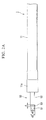
- FIG. 1 is a front view showing a treatment device for electrosurgery 1 (hereinbelow, referred to as a "treatment device 1") of the present embodiment.
- a treatment device 1 a treatment device for electrosurgery 1
- the portion indicated by a reference sign 20 and the portion indicated by a reference sign 50 are shown in different scales.
- the direction indicated by a reference sign A is the distal end direction
- the direction indicated by a reference sign B is the proximal end direction.
- the treatment device 1 includes an insertion portion 10 that can be inserted into a body cavity, an operation portion 20 that is connected to the insertion portion 10 and receives the input of a treatment operation by a user, and a power supply portion 30 that is connected to the insertion portion 10 and the operation portion 20 and can be connected to a high-frequency power supply device (not shown).
- the insertion portion 10 includes a cylindrical sheath 11 that extends in the longitudinal direction of the insertion portion 10. To a distal end portion 11a in the sheath 11, a needle-like electrode portion 50 as a treatment portion that treats a site to be treated is provided.
- the operation portion 20 includes a body 21 that is fixed to a proximal end 11b of the sheath 11, a ring-like finger-hooking portion 22 that is provided to the proximal end of the body 21, and a handle 40 that is connected to the body 21 and moves forward and backward in the longitudinal direction of the body 21.
- the handle 40 includes finger-hooking portions 41 and 42 in which ring-like through-holes 41a and 42a for hooking fingers of a user are formed.
- the power supply portion 30 includes a connector 31 that is connected to a power supply device (not shown), a power line 32a extend toward the connector 31 from the sheath 11, and a power line 32b extend toward the connector 31 from the handle 40.
- FIG. 2A is an enlarged front view showing the configuration of a portion of the treatment device 1, which shows the configuration of the distal end portion 11a of the sheath 11.
- the needle-like electrode portion 50 includes, as portions that can be exposed to the outside, a first electrode 51 that is positioned at the distal end, a second electrode 52 that is positioned at the proximal end with respect to the first electrode 51, and an insulator 53 that is positioned between the first electrode 51 and the second electrode 52.
- the side of the first electrode 51 is a distal end side.
- the first electrode 51 and the second electrode 52 are configured so as to contact a body tissue at the same time.
- the first electrode 51 is configured with a diameter smaller than that of the second electrode 52, and the insulator 53 is formed at a slope that connects a level difference between the first electrode 51 and the second electrode 52 in the radial direction.
- a diameter d1 of the first electrode 51 is preferably 0.5 mm or less
- a diameter d2 of the second electrode 52 is preferably from 0.5 mm to 1.0 mm.
- a gap g which is a distance between the first electrode 51 and the second electrode 52 in the axial direction toward the proximal end from the distal end of the needle-like electrode portion 50, is preferably from 0.1 mm to 0.5 mm.
- the first electrode 51 is a member for incising a body tissue by contacting the body tissue
- the second electrode 52 is a passive electrode with respect to the first electrode 51.
- the surface area of the second electrode 52 is larger than that of the first electrode 51.
- the contact area between the first electrode 51 and the body tissue is preferably smaller than the contact area between the second electrode 52 and the body tissue.
- FIG. 2B is an enlarged cross-sectional view showing the configuration of a portion of the treatment device 1.
- a conductive wire 54 that extends in the proximal end direction is fixed to the first electrode 51.
- a conductive wire 55 is also fixed to a proximal end portion 54a of the wire 54 and further extends to the proximal end.
- an insulation portion 58 having an insulation property is formed in the circumferential surface of the wire 55.
- the second electrode 52 is formed in cylindrical shape, and is inserted into a conductive contact member 13 that is fixed to the distal end portion 11a of the sheath 11, so as to freely move forward and backward.
- a flange portion 52a is formed in a shape of a flange protruding to the outside in the radial direction.
- a step portion 13a is formed to have a contact surface concentric to the flange portion 52a.
- the wire 54 is inserted into the second electrode 52.
- the wire 54 and the second electrode 52 are concentrically supported by being fixed to each other due to a second insulator 53a interposed between the second electrode 52 and the wire 54.
- the second insulator 53a includes a flange portion 53b that is adjacent to the proximal end of the flange portion 52a of the second electrode 52.
- cylindrical members 56 and 57 having an insulation property are fixed to the more proximal end of a flange portion 53b in the second insulator 53a.
- the contact member 13 is fixed and electrically connected to a conductive coil sheath 12.
- the coil sheath 12 of the present embodiment is a multi-thread coil that is formed while being densely wound in a spiral in the circumferential direction of the sheath 11 along the inner wall of the sheath 11.
- the coil sheath 12 is also a driving force-transmitting member that transmits a driving force of forward and backward operations in the axial direction or a rotation operation around the axis of the sheath 11, which is caused when the user operates the treatment device 1, to the distal end portion 11a from the proximal end portion 11b.
- FIG. 3 is an enlarged cross-sectional view showing the configuration of a portion of the treatment device 1. As shown in FIG. 3 , the sheath 11 is fixed to the distal end of the operation portion 20. The coil sheath 12 and the wire 55 inserted into the sheath 11 extend to the operation portion 20.
- the coil sheath 12 is fixed and electrically connected to a contact member 14 positioned inside the sheath 11 at the distal end of the operation portion 20.
- the contact member 14 is electrically and physically connected to the power line 32a.
- a through-hole in which the wire 55 can be inserted while freely moving forward and backward is formed.
- the wire 55 further extends toward the operation portion 20 through the through-hole of the contact member 14, and is disposed inside the body 21 of the operation portion 20.
- a proximal end 55b of the wire 55 is fixed to the power line 32b via an electrode portion 43 provided to the handle 40.
- the members from the power line 32b to the first electrode 51 are electrically connected to each other, and function as a first conductive portion to be applied with a high-frequency current.
- the members from the power line 32a, the coil sheath 12, the contact member 13, and the second electrode 52 are configured so as to be able to be electrically connected to each other, and function as a second conductive portion to be applied with a high-frequency current.
- FIG. 4 is a flowchart showing the operation of the treatment device 1
- FIGS. 5A to 5C are views showing a process performed when the treatment device 1 is used.
- Step S1 is a pre-treatment step for using the treatment device 1 of the present embodiment. That is, Step 1 is a step of making it possible to endoscopically guide the treatment device 1 to a target site to be treated.
- Step S 1 first, Step S11 as a step of inserting an endoscope into a body cavity is performed.
- Step S11 an endoscope including an insertion portion that can be inserted into a body cavity and a treatment tool channel in which a treatment tool or the like can be inserted is inserted into a body cavity by means of an appropriate procedure according to the type or site of the target site.
- the endoscope In order to insert the endoscope into a body cavity, the endoscope is inserted through natural orifices such as the mouth, or a small incision is made at an appropriate site so as to guide the endoscope to the target site, for example.
- the process proceeds to Step S12 from Step S11.
- Step S12 is a step of guiding the insertion portion of the endoscope to the target site in the body cavity.
- Step S12 the inside of the body cavity is observed using an observation optical system in the endoscope.
- the endoscope is inserted into the body cavity until the distal end of the endoscope is positioned at the target site, and the distal end of the endoscope is guided to the target site.
- Step 13 as a step of checking the target site is performed.
- the target site is observed using the observation optical system described above, whereby the user or the like diagnoses or checks the target site.
- Step S1 is completed in the above manner, and the process proceeds to Step S2.
- Step S2 is a step of treating the target site by using the treatment device 1 of the present embodiment.
- the treatment device 1 is ready in a state where the connector 31 of the power supply portion 30 is connected to a power supply device.
- Step S21 begins.
- Step S21 the handle 40 shown in FIG. 1 is pulled to the proximal end so as to be close to the finger-hooking portion 22.
- the wire 55 shown in FIG. 2B is pulled to the proximal end, and the needle-like electrode portion 50 is housed inside the sheath 11.
- Step S21 is completed in this manner, and the process proceeds to Step S22.
- Step S22 is a step of advancing the first electrode 51 of the needle-like electrode portion 50 such that the first electrode 51 can contact the target site.
- the handle 40 shown in FIG. 1 is pushed out to the distal end of the body 21, and the needle-like electrode portion 50 is advanced from the distal end portion 11a of the sheath 11.
- the first electrode 51 stops at a point in time when the distal end thereof is advanced from the distal end portion 11a of the sheath 11 by the length L described above.
- the flange portion 52a of the second electrode 52 contacts the step portion 13a of the contact member 13.
- Step S22 is completed in this manner, and the process proceeds to Step S23.
- Step S23 is a step of incising the target site by using the needle-like electrode portion 50.
- the first electrode 51 and the second electrode 52 of the needle-like electrode portion 50 contact a target site T, as shown in FIG. 5A .
- the target site T is, for example, a soft tissue
- the outer surface of each of the first electrode 51 and the second electrode 52 tightly adheres to the target site T.
- the area of the portion where the first electrode 51 contacts the target site T is smaller than the area of the portion where the second electrode 52 contacts the target site T. Accordingly, in the target site T, the body tissue positioned at the first electrode 51 is incised.
- the user moves the needle-like electrode portion 50 along a predetermined incision area in the target site T by operating the endoscope and the treatment device 1, as shown in FIG. 5B , for example. Then the target site T is incised along the movement trajectory of the first electrode 51 due to the high-frequency current applied, as shown in FIG. 5B .
- the positional relationship between the sheath 11 and the target site T changes in some cases. For example, as shown in FIG. 5C , between a first position X where the distal end portion 11a of the sheath 11 contacts a site T1 near the target site T and a second position Y where the distal end portion 11a of the sheath 11 contacts the site T1 near the target site T, the positional relationship between the sheath 11 and the target site T changes.
- a passive electrode with respect to the needle like electrode is disposed at a position corresponding to the distal end portion 11a of the sheath 11. Accordingly, in the devices used hitherto, the high-frequency current can be applied to the body tissue placed between the needle-like electrode and the passive electrode, in the first position X. However, in the devices used hitherto, the high-frequency current cannot be applied to the body tissue placed between the needle-like electrode and the passive electrode, in the second position Y.
- the treatment device 1 of the present embodiment whether the positional relationship between the target site T and the treatment device 1 is established in the first position X or in the second position Y, the second electrode 52 contacts a target site T2 near the target site T. Consequently, the treatment device 1 of the present embodiment can apply the high-frequency current to the body tissue placed between the first electrode 51 and the second electrode 52, at any position between the first position X and the second position Y.
- the treatment device 1 When the incision of the target site T is completed, the treatment device 1 is pulled out of the body cavity, and appropriate treatment is performed on the target site T. Alternatively, the treatment is completed by pulling the treatment device 1 and the endoscope out of the body cavity.
- the first electrode 51 is provided to the distal end of the needle-like electrode portion 50, and the relative positional relationship with respect to the first electrode 51 is fixed.
- the second electrode 52 is provided to the proximal end of the first electrode 51 via the insulator 53. Accordingly, even when the positional relationship of the treatment device 1 with respect to the target site T changes, the contact between the first electrode 51 as well as the second electrode 52 and the target site T is maintained. Therefore, the flow of high-frequency current applied to the target site T is suppressed from being interrupted, and the body tissue can be easily incised.
- the coil sheath 12 is electrically connected to the second electrode 52 via the contact member 13. Moreover, the high-frequency current is applied to the second electrode 52 through the coil sheath 12. Accordingly, a member that transmits a driving force to the distal end portion 11a of the sheath 11 can also be used as a member for applying the high-frequency current. Consequently, complete parts inside the sheath 11 can be reduced. Therefore, the diameter of the insertion portion 10 can be reduced.
- the treatment device 1 is a bipolar device that treats a target site by inserting both the first electrode 51 and the second electrode 52 into a body cavity. Therefore, it is not necessary to separately provide a passive electrode corresponding to the first electrode 51 for incising a body tissue of the target site. As a result, the treatment device 1 is easily operated.
- the area to which the high-frequency current is applied becomes a portion of the body tissue that the first electrode 51 and the second electrode 52 contact. Accordingly, compared to the device in which a passive electrode is disposed in the sheath as in the related art, incision can be performed in an area that is further localized to the position of the first electrode.
- FIG. 6 is a cross-sectional view showing the configuration of a portion of a treatment device for electrosurgery of the present modified example.
- the treatment device 1 includes a second electrode 52a instead of the second electrode 52.
- a second insulator 59 having an insulation property is provided to the circumferential surface of the second electrode 52a.
- the second insulator 59 is fixed to the second electrode 52a so as to cover a portion of the circumferential surface of the second electrode 52a.
- the second insulator 59 is disposed in the axis direction extending toward the proximal end from the distal end, while being separated from the insulator 53.
- the surface area of the second electrode 52a that is exposed to the outside between the insulator 53 and the second insulator 59 is preferably the same as the surface area of the first electrode 51 that is exposed to the outside at the distal end from the insulator 53.
- the area where the first electrode 51 contacts the target site T is approximately the same as the area where the second electrode 52a contacts the target site T. Accordingly, when the high-frequency current is applied to the body tissue placed between the first electrode 51 and the second electrode 52a, the body tissue in an area between the first electrode 51 and the second electrode 52a is incised in the target site T.
- the first electrode 51 and the second electrode 52a keep contacting the body tissue. Accordingly, the flow of high-frequency current applied to the target site T is suppressed from being interrupted, and the body tissue can be easily incised.
- Modified Example 2 of the treatment device 1 of the present embodiment will be described with reference to FIGS. 7A to 8D .
- other configuration examples of the treatment portion in the treatment device 1 will be described.
- FIGS. 7A and 7B are front views showing a first configuration example of the treatment portion in the treatment device 1 of the present modified example.
- the treatment portion in the present configuration example is a bent electrode portion 150 that is provided instead of the needle-like electrode portion 50.
- the bent electrode portion 150 includes a hook-type electrode 151 instead of the first electrode 51 described above.
- the hook-type electrode 151 is the same as the first electrode 51 in respect that the hook-type electrode 151 is a first electrode with respect to the second electrode 52.
- the hook-type electrode 151 forms a hook shape with a shaft portion 151a that extends in the distal end direction from the insulator 53 and a bent portion 151b that extends in one direction orthogonal to the axial direction of the sheath in the distal end.
- the distance between the distal end of the sheath 11 and the distal end of the hook-type electrode 151 is restricted to the length L, similarly to the needle-like electrode portion 50 described above.
- the hook-type electrode 151 and the second electrode 52 are brought into contact with the target site T, and the high-frequency current is applied between the hook-type electrode 151 and the second electrode 52, whereby the body tissue can be incised in the same manner as the needle-like electrode portion 50.
- the hook-type electrode 151 is brought into contact with the target site T in a direction in which a step portion 151c of the bent portion 151b is buried under the body tissue, the body tissue of the target site T can be incised at a position deeper than that of the first electrode 51.
- FIGS. 8A to 8D are views showing a second configuration example of the treatment portion in Modified Example 2 of the treatment device 1.
- FIG. 8A is a front view
- FIG. 8B is a lateral cross-sectional view
- FIGS. 8C and 8D are lateral views showing the treatment device 1 at the time of being used.
- the treatment device 1 includes a triangular electrode portion 160 as a treatment portion instead of the needle-like electrode portion 50.
- the triangular electrode portion 160 includes, instead of the first electrode 51, a triangular chip 161 that extends in the radial direction with respect to the axial direction extending toward the distal end from the proximal end.
- the triangular chip 161 is the same as the first electrode 51, in respect that the triangular chip 161 is a first electrode with respect to the second electrode 52.
- top electrodes 161 a, 161 b, and 161c are formed in the positions of the vertices of an equilateral triangle having the wire 54 as a central position, which is shown in the front view of FIG. 8A .
- the top electrodes 161a, 161 b, and 161 c can be brought into contact with the target site T such that these electrodes are hooked to the body tissue.
- the second electrode 52 also contacts the body tissue. Accordingly, the high-frequency current is applied between the top electrode contacting the body tissue among the top electrodes 161 a, 161 b, and 161 c and the second electrode 52 contacting the body tissue, whereby the body tissue of the target site T can be incised.
- FIGS. 9A and 9B are cross-sectional views showing the configuration of a portion of the treatment device 1 of the present modified example.
- a biasing member 60 that elongates and contracts along the axial direction of the sheath 11 is provided to the inside of the distal end portion 11a of the sheath 11.
- an end portion 60a that is positioned at the distal end of the sheath 11 contacts the contact member 13.
- an end portion 60b that is positioned at the proximal end of the sheath 11 contacts the flange portion 52a.
- the biasing member 60 is configured in a shape of a coil spring of which the core material is stainless steel and the outer surface is covered with a film of gold, silver, or nickel showing higher conductivity compared to the stainless steel.
- the biasing member 60 has elasticity and electrical conductivity. The biasing member 60 biases the contact member 13 and the flange portion 52a in a direction in which the contact member 13 is separated from the flange portion 52a in the axial direction of the sheath 11.
- the treatment device 1 of the present modified examples includes, as routes for applying the high-frequency current to the second electrode 52, a route in which the flange portion 52a at the proximal end of the second electrode 52 becomes conductive with the contact member 13 via the biasing member 60, and a route in which the circumferential surface of the second electrode 52 conduct with the contact member 13.
- the flange portion 52a is separated from the contact member 13 in the axial direction of the sheath 11.
- the biasing member 60 undergoes elastic deformation so as to elongate in the axial direction of the sheath 11, the high-frequency current is kept being applied between each of the contact member 13 and the flange portion 52a and the biasing member 60.
- the treatment device 1 of the present modified example includes a route for applying the high-frequency current to the second electrode 52 via the biasing member 60, in addition to a route for bringing the circumferential surface of the sheath 11 into contact with the contact member 13. Accordingly, the treatment device 1 of the present modified example can reliably apply the high-frequency current to the second electrode 52, regardless of the protruding amount by which the needle-like electrode portion 50 protrudes from the sheath 11.
- the treatment device 1 of the present modified example it is possible to use the treatment device 1 in a state where the protruding amount by which the needle-like electrode portion 50 protrudes from the distal end portion 11 a of the sheath 11 has been adjusted to a protruding amount of protrusion that is optimal for treating the target site T.
- FIG. 10 is a front view showing the treatment device 500
- FIG. 11 is a cross-sectional view showing the configuration of a portion of the treatment device 500.
- the configuration of the treatment device 500 is different from the configuration of the treatment device 1, in respect that the treatment device 500 includes a needle-like electrode portion 550 provided instead of the needle-like electrode portion 50 and an enlarged passive electrode 554 provided instead of the distal end portion 11a of the sheath 11.
- the needle-like electrode portion 550 includes a first electrode 551 that is positioned at the distal end, a second electrode 552 that is positioned at the proximal end with respect to the first electrode 551, and an insulator 553 that is positioned between the first electrode 551 and the second electrode 552.
- the first electrode 551 is formed in a semispherical shape (including an approximately semispherical shape) that bulges to the outside in the radial direction of the second electrode 552 in the proximal end and decreases its diameter toward the distal end.
- first conductive portion 515 that extends in the axial direction of the sheath 11 is fixed to the first electrode 551 by, for example, laser welding.
- the first conductive portion 515 is formed of an electroconductive wire rod.
- the first conductive portion 515 extends from the distal end portion 11a of the sheath 11, coaxially with the central axis of the sheath 11. Inside the sheath 11, the first conductive portion 515 is deviated due to an approximately cylindrical connecting member 557 so as to be located at a position eccentric from the central axis of the sheath 11.
- the first conductive portion 515 extends toward the operation portion 20 inside the sheath 11.
- An insulating film 516 having an insulation property is provided to the circumferential surface of the first conductive portion 515.
- the insulating film 516 is formed of, for example, a resin.
- the second electrode 552 is formed in cylindrical shape that extends in the axial direction of the sheath 11.
- An extending portion 552a extending to the outside in the radial direction is integrally formed in the distal end of the second electrode 552.
- the extending portion 552a is formed in, for example, a shape in which three projections that extend toward the outside of the radial direction of the second electrode 552 are provided every 120° in the circumferential direction, based on the axis of the second electrode 552 as a center.
- the shape and number of the projections can be set to appropriate shapes and numbers.
- the proximal end of the second electrode 552 is fixed to a second conductive portion 512 via the connecting member 557.
- the connecting member 557 has electrical conductivity, and the high-frequency current can be applied between the second conductive portion 512 and the second electrode 552.
- the insulator 553 is fixed to the proximal end of the first electrode 551.
- the material of the insulator 553 the same material as that of the insulator 53 of the first embodiment can be used.
- the insulator 553 is formed of, for example, an insulating material such as a ceramic.
- the first electrode 551 is a passive electrode with respect to the second electrode 552.
- the second electrode 552 functions as an incision electrode for incising an adult tissue. That is, in a state where both the first electrode 551 and the second electrode 552 are contacting the body tissue, the contact area between the first electrode 551 and the body tissue is set so as to be larger than the contact area between the second electrode 552 and the body tissue.
- the same electric potential as that of the first electrode 551 is supplied to the enlarged passive electrode 554, and the enlarged passive electrode 554 functions as a passive electrode.
- a portion of the enlarged passive electrode 554 is inserted into the distal end portion 11a of the sheath 11, and the material of the enlarged passive electrode 554 is, for example, stainless steel.
- the enlarged passive electrode 554 has electrical conductivity.
- the enlarged passive electrode 554 is connected to the coil sheath 12 inside the sheath 11.
- the enlarged passive electrode 554 is connected to the coil sheath 12 by means of, for example, laser welding.
- the high-frequency current can be applied between the enlarged passive electrode 554 and the sheath 12.
- the coil sheath 12 and the first conductive portion 515 function as conductive portions having the same electrical potential.
- An insulator 558 having an insulation property is interposed between the enlarged passive electrode 554 and the second electrode 552.
- the insulator 558 is provided while protruding toward the distal end from the enlarged passive electrode 554. Accordingly, in the positional relationship in which the insulator 558 contacts an extending portion 551a, the insulator 558 does not contact the enlarged passive electrode 554.
- FIGS. 12A to 12C are views for illustrating the operation at the time of using the treatment device 500.
- a small incision to be a starting point of the incision is made in the target site T.
- the first electrode 551 of the treatment device 500 is inserted into an aperture that has been formed in the target site T due to the small incision.
- the user inserts the first electrode 551 straightly into the aperture formed in the target site T, in the depth direction of the aperture. Then the bottom of the aperture of the target site T contacts the outer surface of the first electrode 551, and the second electrode 552 and the extending portion 552a contact the sidewall portion of the aperture.
- the user of the treatment device 500 applies the high-frequency current to the treatment device 500.
- the high-frequency current is applied between the first electrode 551 and the second electrode 552 via the target site T.
- the target site T contacting the second electrode 552 and the extending portion 552a is incised with cauterization.
- the user moves the needle-like electrode portion 550 in the direction of incision as shown in FIG. 12C .
- the proximal end in the first electrode 551 moves in the direction of incision as the target site T is incised while being hooked on the target site T.
- the enlarged passive electrode 554 may contact the body tissue around the target site T.
- the first electrode 551 that functions as a passive electrode is in a positional relationship in which the first electrode 551 is buried inside the target site T. Accordingly, while the target site T is being incised, the passive electrode is not separated from the target site T.
- the second electrode 552 having a fixed positional relationship in the insulator 553 is interposed between the first electrode 551 and the second electrode 552 that is positioned at the proximal end from the first electrode 551 functions as an incision electrode incising the target site T. Accordingly, while the first electrode 551 is being buried inside the target site T, the second electrode 552 contacts the target site T. Consequently, it is not necessary to perform an operation for bringing both the first electrode 551 and the second electrode 552 into contact with the target site T. As a result, the user of the treatment device 500 can concentrate on the incision operation of the target site T.
- the first electrode 551 is positioned according to the depth of the small incision formed in the target site T. Therefore, since the target site T can be incised by moving the electrode in the incision direction with the depth, the depth of the needle-like electrode portion 550 inserted into the target site T can be set to a constant depth.
- the treatment device 500 may not include the enlarged passive electrode 554.
- the coil sheath 12 is not necessarily a member that can be applied with the high-frequency current. Even in this case, the same effects as that of the treatment device 500 of the present embodiment can be produced.
- FIGS. 14 to 17 a treatment device for electrosurgery according to the third embodiment of the present invention will be described with reference to FIGS. 14 to 17 .
- the portions common to those in the configuration of the treatment device for electrosurgery according to the first embodiment are marked with the same reference signs, and description thereof is omitted.
- FIG. 14 is a front view showing the treatment device for electrosurgery of the present embodiment.
- a treatment device for electrosurgery 200 (hereinbelow, referred to as a "treatment device 200") of the present embodiment includes a snare loop 250 instead of the needle-like electrode portion 50.
- the configuration of the treatment device 200 is different from the configuration of the treatment device 1 of the first embodiment in respect that the treatment device 200 includes a snare loop 250 instead of the needle-like electrode portion 50 and further includes an enlarged second electrode 270 provided to the outer surface of the distal end portion 11a of the sheath 11, in addition to the second electrode 52.
- the snare loop 250 has a ring-like exterior.
- the snare loop 250 includes a conductive first electrode 251, a second electrode 252 that is positioned at the proximal end from the first electrode 251, and an insulator 253 that is positioned between the first electrode 251 and the second electrode 252.
- the first electrode 251 can be applied with the high-frequency current and has elasticity.
- the first electrode 251 is a portion of the distal end in a wire 255 that is a core material of the snare loop 250, and is an area of the distal end from the insulator 253.
- the wire 255 is formed so as to make a ring-like loop by being folded back at the distal end.
- the size of the first electrode 251 is set to an appropriate size according to the positional relationship between the wire 255 and the insulator 253.
- the size of the first electrode 251 is preferably set according to the target site T, such that the outer surface of the wire 255 having a length which can be hooked around the target site T such as the neck portion of a polyp P (see FIG. 16 ) is exposed.
- the second electrode 252 is a conductive tubular member that is provided on the circumferential surface of the wire 255 so as to cover the wire 255 via the insulator 253.
- the insulator 253 is provided so as to cover the wire described above, such that at least a portion of the insulator 253 is exposed to the outside between the first electrode 251 and the second electrode 252.
- FIG. 15 is a partial cross-sectional view showing a portion of the distal end portion 11a of the sheath 11 of the treatment device 200.
- the wire 255 of the snare loop 250 extends to the proximal end through the inside of the sheath 11.
- the end portion of the wire 255 at the proximal end is fixed to the handle 40 and the power line 32b, similarly to the treatment device 1 of the first embodiment (see FIGS. 14 and 3 ).
- a fixing tube 252a tying two strands of the wire 255 that are formed due to the wire 255 being folded back is fixed to a portion of the proximal end in the second electrode 252.
- the fixing tube 252a has conductivity.
- the fixing tube 252a is a member that becomes conductive by contacting the contact member 13.
- the handle 40 is caused to move to the distal end of the body 21 in the operation portion 20 shown in FIG. 14 , whereby the fixing tube 252a contacts the contact member 13. Due to the contact between the fixing tube 252a and the contact member 13, the length by which the snare loop 250 protrudes from the distal end of the sheath 11 is restricted to the length L shown in FIG. 14 .
- the electrical connection between the second electrode 252 and the contact member 13 is formed when the outer surface of the second electrode 252 contacts an inner surface 13b of the contact member 13 due to the elasticity of the wire 255.
- the second electrode 252 is electrically connected to the enlarged second electrode 270, when each second electrode 252 is inserted into the enlarged second electrode 270.
- the enlarged second electrode 270 is integrally molded with the contact member 13. That is, the enlarged second electrode 270 is fixed and electrically connected to the coil sheath 12 similarly to the contact member 13 while functioning as the contact member 13.
- the second electrode 252 is conductive with the enlarged second electrode 270. Accordingly, both the second electrode 252 and the enlarged second electrode 270 function as a passive electrode with respect to the first electrode 251.
- Step S1 and Step S21 shown in FIG. 3 are performed, similarly to the treatment device 1.
- Step S22 performed after Step S21 the user moves the handle 40 to the distal end of the body 21, whereby the snare loop 250 is advanced from the distal end portion 11a of the sheath 11. Then, the snare loop 250 is enlarged due to the elasticity of the wire 255 and becomes a ring shape.
- FIGS. 16 and 17 are views showing a process performed when the treatment device 200 is used.
- Step S23 the snare loop 250 is hooked around a neck portion of a polyp P (target site T in the present embodiment) due to the operation of the user, as shown in FIGS. 16 and 17 .
- the user moves the handle 40 to the proximal end of the body 21.
- the snare loop 250 hooked around the polyp P moves to the inside of the sheath 11, and the target site T is pulled and draw by the first electrode 251 which is a portion at the distal end of the snare loop 250.
- the enlarged second electrode 270 is pressed on the polyp P.
- the high-frequency current is applied between the first electrode 251 and the second electrode 252.
- the target site T is incised, and the polyp P is excised.
- the first electrode 251 is provided to the distal end of the ring-like snare loop 250, and the second electrode 252 is provided to the proximal end of the snare loop 250 via the insulator 253. Accordingly, even if the positional relationship of the treatment device 1 is changed with respect to the target site T, the first electrode 251 and the second electrode 252 keep contacting the target site T. Consequently, the flow of high-frequency current applied to the target site T is suppressed from being interrupted, and the body tissue can be easily incised.
- the biasing member 60 may be provided to the inside of the sheath 11, similarly to Modified Example 3 of the treatment device 1 of the first embodiment. Specifically, as shown in FIG. 18A , the biasing member 60 is connected to the fixing tube 252a and to the contact member 13, and biases the fixing tube 252a and the contact member 13 in the direction in which the fixing tube 252a is separated from the contact member 13 in the axial direction of the sheath 11. In this case, when the snare loop 250 is pulled to the inside of the sheath 11, it is possible to cause the contact member 13 to be reliably conductive with the second electrode 252.
- the treatment device 200 may include both the biasing member 60 and the second passive electrode 270.
- FIG. 19 is a front view showing the treatment device for electrosurgery of the present embodiment.
- a treatment device for electrosurgery 300 (hereinbelow, referred to as a "treatment device 300") of the present embodiment includes a two-legged incision portion 350 instead of the needle-like electrode portion 50.
- the two-legged incision portion 350 includes a pair of elastic gripping portions 351 that is slanted so as to face the axis direction extending toward the distal end from the proximal end and to face the outer direction of the radial direction of the sheath 11.
- FIG. 20 is a partial cross-sectional view showing part of the distal end portion 11a of the sheath 11 of the treatment device 300.
- each of the elastic gripping portions 351 includes a hooking portion 351a formed in a shape in which the end portion thereof is bent in a direction approaching the other hooking portion 351a at the distal end, in an area near the end portion of the distal end of an elastic wire 355 which can be applied with the high-frequency current.
- a second electrode 352 of which the relative positional relationship to the elastic gripping portion 351 is fixed and which is provided so as to cover the wire 355, and an insulator 353 which is interposed between the elastic gripping portion 351 and the second electrode 352 and fixed to cover the wire 355 are provided.
- the elastic gripping portion 351 is a first electrode with respect to the second electrode 352.
- the proximal end portion in the second electrode 352 is fixed by being tied with a fixing cylinder 252a, similarly to the treatment device 200 of the third embodiment.
- the treatment device 300 includes the same enlarged second electrode 270 as that of treatment device 200.
- FIGS. 21 and 22 are views showing a process performed when the treatment device 300 of the present embodiment is used.
- FIG. 21 in using the treatment device 300, when the two-legged incision portion 350 has been advanced from the distal end portion 11a of the sheath 11, each of the elastic gripping portions 351 is positioned so as to be separated from each other due to the elasticity of the wire 355.
- the position of the two-legged incision portions 350 is adjusted such that the target site T is positioned between the pair of elastic gripping portions 351.
- the two-legged incision portion 350 moves to the inside of the sheath 11 as shown in FIG. 22 , and each of the elastic gripping portions 351 operates so as to approach each other, thereby contacting the target site T.
- the outer surface of the second electrode 352 and the inner surface of the sheath 11, more specifically, the outer surface of the second electrode 352 and the inner surface 13b of the contact member 13 come in contact with each other.
- the second electrode 352 contacts the contact member 13 such that the second electrode 352 is pressed on the inner surface of the contact member 13 due to the elasticity of the wire 355. Accordingly, the second electrode 352 becomes conductive with the contact member 13 such that the high-frequency current can be applied therebetween.
- the outer surface of the polyp P contacts the enlarged second electrode 270.
- the handle 40 further moves to the proximal end of the body 21, and the high-frequency current is applied between the elastic gripping portion 351 and the second electrode 352. Then the body tissue positioned in the target site T is incised with cauterization between the elastic gripping portion 351 and the second electrode 352, whereby the polyp P is excised.
- the elastic gripping portion 351 is provided to the distal end of the two-legged incision portion 350.
- the second electrode 352 is provided to the proximal end of the elastic gripping portion 351 via the insulator 353. Accordingly, even if the positional relationship of the treatment device 1 is changed with respect to the target site T, the elastic gripping portion 351 and the second electrode 352 keep contacting the target site T. Consequently, the flow of high-frequency current applied to the target site T is suppressed from being interrupted, and the body tissue can be easily incised.
- the biasing member 60 may be provided to the inside of the sheath 11 similarly to Modified Example 3 of the treatment device 1 of the first embodiment, as shown in FIG. 23A .
- the treatment device 300 may include the biasing member 60 and the second passive electrode 270.
- FIG. 24 is a front view showing the treatment device for electrosurgery of the present embodiment.
- a treatment device for electrosurgery 400 (hereinbelow, referred to as a "treatment device 400") of the present embodiment includes a needle-like electrode portion 450 instead of the needle-like electrode portion 50.
- the configuration of the treatment device 400 is different from the configuration of the treatment device 1 of the first embodiment, in respect that the needle-like electrode portion 450 further includes an enlarged second electrode 452 which is provided to the outer surface of the distal end portion 11a of the sheath 11, in addition to the second electrode 52.
- FIG. 25 is a enlarged cross-sectional view showing the configuration of the distal end portion 11a of the sheath 11 in the treatment device 400.
- the second electrode 52 is electrically connected to the enlarged second electrode 452, in the distal end portion 11a of the sheath 11.
- the enlarged second electrode 452 is integrally molded with the contact member 13. That is, the enlarged second electrode 452 is fixed and electrically connected to the coil sheath 12 similarly to the contact member 13 while functioning as the contact member 13.
- the second electrode 52 is conductive with the enlarged second electrode 452, so the second electrode 52 and the enlarged second electrode 452 function as a passive electrode with respect to the first electrode 51.
- FIG. 26 is a view showing an operation at the time of using the treatment device 400.
- the treatment device 400 is guided into the body cavity similarly to the treatment device 1 of the first embodiment and further guided to a body tissue to be treated.
- the first electrode 51 and the second electrode 52 contacts the target site, similarly to the first embodiment.
- the user brings the first electrode 51 into contact with the target site, whereby the second electrode 52 also contacts the body tissue.
- the enlarged second electrode 452 also contacts the body tissue.
- the high-frequency current is applied between the first electrode 51 and the second electrode 52, and the high-frequency current is applied between the first electrode 51 and the enlarged second electrode 452. Accordingly, the body tissue that the first electrode 51 having a relatively small contact area with respect to the body tissue contacts is incised with cauterization.
- the enlarged second electrode 452 is provided in addition to the second electrode 52, the total surface area of the passive electrode that can contact the body tissue is large.
- the current is still applied between the first electrode 51 and the passive electrode. Accordingly, even when the user moves the first electrode 51 to a desired position, the user can continuously incise the body tissue suitably without caring about how the second electrode 52 and the enlarged second electrode 452 contact the body tissue.
- the enlarged second electrode 452 is provided to the sheath 11 having a relatively larger outer diameter compared to the first electrode. Accordingly, the enlarged second electrode 452 easily contacts the body tissue in the space of the target site T. As a result, it is possible to secure a sufficient contact area of the passive electrode with respect to the body tissue.
- the enlarged second electrode 452 may include the biasing member 60 described in Modified Example 3 of the first embodiment. In this case, even if the protruding amount by which the first electrode 51 protrudes from the sheath 11 is changed, and the positional relationship between the first electrode 51 and the enlarged second electrode 452 is changed, it is possible to apply the high-frequency current between the second electrode 52 as well as the enlarged second electrode 452 and the first electrode 51 via the target site T.
- the treatment device for electrosurgery of the present invention it is possible to easily incise a body tissue placed between the first and second electrodes.
Abstract
Description
- The present invention relates to a treatment device for electrosurgery. Priority is claimed on Japanese Patent Application No.
2010-018130, filed January 29, 2010 - Conventionally, in the medical field or the like, a treatment tool in which a treatment portion that treats a body tissue is provided to the distal end of an insertion portion inserted into a body cavity is known. Particularly, as a treatment tool that performs a surgical treatment, such as making an incision, on a body tissue, a treatment device for electrosurgery which cauterizes and incises a body tissue contacting a treatment portion by applying a high-frequency current to the treatment portion is known.
This type of treatment device for electrosurgery is broadly classified into a treatment device for so-called monopolar electrosurgery that includes a first electrode inserted into a body cavity and a second electrode disposed on the body surface, and a treatment device for so-called bipolar electrosurgery that includes first and second electrodes disposed in a body cavity. - For example,
Patent Document 1 discloses a treatment device for bipolar electrosurgery. This treatment device for bipolar electrosurgery disclosed inPatent Document 1 includes an electrode (passive electrode) that is provided to the distal end portion of a catheter tube and an electrode (incision electrode) that is provided so as to be able to move in the catheter tube. According to this treatment device for bipolar electrosurgery, an opposite electrode (the second electrode described above) does not need to be provided outside the body of a patient, and it is possible to incise the body tissue while suppressing invasiveness to the body tissue. - In addition,
Patent Document 2 discloses a high-frequency incision tool that incises a body tissue by using a snare applied with a high-frequency current. This high-frequency incision tool disclosed inPatent Document 2 includes a sheath that is formed of an outer tube and an inner tube having an electrical insulation property, an operation wire that is inserted into the sheath so as to freely move forward and backward and performs an operation for the forward and backward movement at the proximal side of the sheath, a snare (incision electrode) that is connected to the distal end of the operation wire, an electrode (passive electrode) that is fixed to the distal end of the sheath while being exposed and contacts a body tissue, and means for conductively connecting the electrodes and the snare to a high-frequency generating device through the inside of the sheath.
According to this high-frequency incision tool, a body tissue to be incised is gripped with the snare, and at this point in time, by causing a high-frequency current to flow, the body tissue can be cauterized. -
- [Patent Document1] Japanese Unexamined Patent Application, First Publication No.
2002-224135 - [Patent Document 2] Japanese Examined Patent Application, Second Publication No.
S61-9061 - However, in the treatment device for bipolar electrosurgery disclosed in
Patent Document 1 and the high-frequency incision tool disclosed inPatent Document 2, it is necessary to bring the incision electrode and the passive electrode into contact with the body tissue at the same time, and to adjust the amount of the tissue incised by appropriately positioning the incision electrode. Accordingly, with the bipolar treatment devices used hitherto, it is necessary to perform the incision while simultaneously checking how the body tissue contacts the two sites including the incision electrode and the passive electrode. As a result, the user is required to be highly skilled. - The present invention has been made in consideration of the above situations, and an object thereof is to provide a treatment device for electrosurgery that can easily incise a body tissue.
- The treatment device for electrosurgery of the present invention includes a sheath that has a distal end and a proximal end, a treatment portion that has a distal end and a proximal end, is inserted into the sheath such that a direction toward the distal end from the proximal end becomes a direction toward the distal end from the proximal end, and treats a target site at the distal end, a first electrode that is provided to the distal end of the treatment portion and exposed to the outside, a second electrode of which the relative positional relationship with respect to the first electrode is fixed at a position separated from the first electrode toward the proximal end in the treatment portion, an insulator that insulates the first electrode from the second electrode by being interposed between the first and second electrodes, a first conductive portion that applies a high-frequency current to the first electrode, and a second conductive portion that applies a high-frequency current to the second electrode.
- The first electrode may be formed while bulging to the outside in the radial direction of the treatment portion so as to have a diameter greater than or equal to the external diameter of the second electrode.
- The first electrode may be formed in a semispherical shape of which the diameter decreases toward the distal end from the proximal end.
- To the distal end of the second electrode, an extending portion that is formed while extending to the outside of the radial direction of the second electrode may be provided.
- An enlarged passive electrode that is provided to the outer surface of the distal end of the sheath and electrically connected to the first electrode may be further included.
- The treatment device for electrosurgery of the present invention preferably further includes an enlarged second electrode that is provided to the outer surface of the distal end of the sheath and electrically connected to the second electrode.
- In the treatment device for electrosurgery of the present invention, the sheath preferably includes an electroconductive coil sheath in the inside thereof, and the coil sheath preferably functions as a portion of the second conductive portion.
- The treatment device for electrosurgery of the present invention preferably further includes a second insulator that hides at least a portion of the outer surface of the second electrode so as to expose a portion of the distal end of the second electrode in the approximately the same area as the surface area of the first electrode.
- In the treatment device for electrosurgery of the present invention, the first electrode may be a portion of a ring-like snare loop having electrical conductivity.
- In the treatment device for electrosurgery of the present invention, the first electrode may be a pair of two-legged forceps having a pair of elastic gripping portions that extend in the distal end direction from the proximal end and can be opened and closed using the proximal end as a center of opening and closing.
- According to the treatment device for electrosurgery of the present invention, the first electrode is disposed at the distal end of the treatment portion that can move inside the sheath, and the second electrode insulated from the first electrode is disposed at the proximal end of the treatment portion, whereby it is possible to easily bring the distal end of the first electrode and the second electrode into contact with the body tissue at the same time. Consequently, it is possible to easily incise the body tissue placed between the first and second electrodes.
-
-
FIG. 1 is a front view showing a treatment device for electrosurgery according to a first embodiment of the present invention. -
FIG. 2A is an enlarged front view showing the configuration of a portion of the treatment device for electrosurgery. -
FIG. 2B is an enlarged cross-sectional view showing the configuration of a portion of the treatment device for electrosurgery. -
FIG. 3 is an enlarged cross-sectional view showing the configuration of a portion of the treatment device for electrosurgery. -
FIG. 4 is a flowchart showing the operation of the treatment device for electrosurgery. -
FIG. 5A is a view showing a process performed when the treatment device for electrosurgery is used. -
FIG. 5B is a view showing a process performed when the treatment device for electrosurgery is used. -
FIG. 5C is a view showing a process performed when the treatment device for electrosurgery is used. -
FIG. 6 is a cross-sectional view showing Modified Example 1 of the treatment device for electrosurgery. -
FIG. 7A is a view showing Configuration Example 1 of Modified Example 2 of the treatment device for electrosurgery. -
FIG. 7B is a view showing Configuration Example 1 of Modified Example 2 of the treatment device for electrosurgery. -
FIG. 8A is a view showing Configuration Example 2 of Modified Example 2 of the treatment device for electrosurgery. -
FIG. 8B is a view showing Configuration Example 2 of Modified Example 2 of the treatment device for electrosurgery. -
FIG. 8C is a view showing Configuration Example 2 of Modified Example 2 of the treatment device for electrosurgery. -
FIG. 8D is a view showing Configuration Example 2 of Modified Example 2 of the treatment device for electrosurgery. -
FIG. 9A is a cross-sectional view showing the configuration of Modified Example 3 of the treatment device for electrosurgery. -
FIG. 9B is a cross-sectional view showing the configuration of Modified Example 3 of the treatment device for electrosurgery. -
FIG. 10 is a front view showing a treatment device for electrosurgery according to a second embodiment of the present invention. -
FIG. 11 is an enlarged cross-sectional view showing the configuration of a portion of the treatment device for electrosurgery. -
FIG. 12A is a view showing an operation performed when the treatment device for electrosurgery is used. -
FIG. 12B is a view showing an operation performed when the treatment device for electrosurgery is used. -
FIG. 12C is a view showing an operation performed when the treatment device for electrosurgery is used. -
FIG. 13 is a cross-sectional view showing another configuration example of the treatment device for electrosurgery. -
FIG. 14 is a front view showing a treatment device for electrosurgery according to a third embodiment of the present invention. -
FIG. 15 is an enlarged cross-sectional view showing the configuration of a portion of the treatment device for electrosurgery. -
FIG. 16 is a view showing an operation performed when the treatment device for electrosurgery is used. -
FIG. 17 is a view showing an operation performed when the treatment device for electrosurgery is used. -
FIG. 18A is a cross-sectional view showing another configuration example of the treatment device for electrosurgery. -
FIG. 18B is a cross-sectional view showing the other configuration example of the treatment device for electrosurgery. -
FIG. 19 is a front view showing a treatment device for electrosurgery according to a fourth embodiment of the present invention. -
FIG. 20 is an enlarged cross-sectional view showing the configuration of a portion of the treatment device for electrosurgery. -
FIG. 21 is a view showing an operation performed when the treatment device for electrosurgery is used. -
FIG. 22 is a view showing an operation performed when the treatment device for electrosurgery is used. -
FIG. 23A is a cross-sectional view showing another configuration example of the treatment device for electrosurgery. -
FIG. 23B is a cross-sectional view showing the other configuration example of the treatment device for electrosurgery. -
FIG. 24 is a front view showing a treatment device for electrosurgery according to a fifth embodiment of the present invention. -
FIG. 25 is an enlarged cross-sectional view showing the configuration of a portion of the treatment device for electrosurgery. -
FIG. 26 is a view showing an operation performed when the treatment device for electrosurgery is used. -
FIG. 27 is a cross-sectional view showing another configuration example of the treatment device for electrosurgery. - Hereinbelow, the treatment device for electrosurgery according to the first embodiment of the present invention will be described with reference to
FIGS. 1 to 6 .FIG. 1 is a front view showing a treatment device for electrosurgery 1 (hereinbelow, referred to as a "treatment device 1") of the present embodiment. In this drawing, the portion indicated by areference sign 20 and the portion indicated by areference sign 50 are shown in different scales. In addition, in the present specification, the direction indicated by a reference sign A is the distal end direction, and the direction indicated by a reference sign B is the proximal end direction. - As shown in
FIG. 1 , thetreatment device 1 includes aninsertion portion 10 that can be inserted into a body cavity, anoperation portion 20 that is connected to theinsertion portion 10 and receives the input of a treatment operation by a user, and apower supply portion 30 that is connected to theinsertion portion 10 and theoperation portion 20 and can be connected to a high-frequency power supply device (not shown). - The
insertion portion 10 includes acylindrical sheath 11 that extends in the longitudinal direction of theinsertion portion 10. To adistal end portion 11a in thesheath 11, a needle-like electrode portion 50 as a treatment portion that treats a site to be treated is provided. - The
operation portion 20 includes abody 21 that is fixed to aproximal end 11b of thesheath 11, a ring-like finger-hookingportion 22 that is provided to the proximal end of thebody 21, and ahandle 40 that is connected to thebody 21 and moves forward and backward in the longitudinal direction of thebody 21. Thehandle 40 includes finger-hookingportions holes - The
power supply portion 30 includes aconnector 31 that is connected to a power supply device (not shown), apower line 32a extend toward theconnector 31 from thesheath 11, and apower line 32b extend toward theconnector 31 from thehandle 40. -
FIG. 2A is an enlarged front view showing the configuration of a portion of thetreatment device 1, which shows the configuration of thedistal end portion 11a of thesheath 11.
As shown inFIG. 2A , the needle-like electrode portion 50 includes, as portions that can be exposed to the outside, afirst electrode 51 that is positioned at the distal end, asecond electrode 52 that is positioned at the proximal end with respect to thefirst electrode 51, and aninsulator 53 that is positioned between thefirst electrode 51 and thesecond electrode 52. In the needle-like electrode portion 50, the side of thefirst electrode 51 is a distal end side. - The
first electrode 51 and thesecond electrode 52 are configured so as to contact a body tissue at the same time. Specifically, thefirst electrode 51 is configured with a diameter smaller than that of thesecond electrode 52, and theinsulator 53 is formed at a slope that connects a level difference between thefirst electrode 51 and thesecond electrode 52 in the radial direction.
For example, a diameter d1 of thefirst electrode 51 is preferably 0.5 mm or less, and a diameter d2 of thesecond electrode 52 is preferably from 0.5 mm to 1.0 mm. In addition, a gap g, which is a distance between thefirst electrode 51 and thesecond electrode 52 in the axial direction toward the proximal end from the distal end of the needle-like electrode portion 50, is preferably from 0.1 mm to 0.5 mm. - The
first electrode 51 is a member for incising a body tissue by contacting the body tissue, and thesecond electrode 52 is a passive electrode with respect to thefirst electrode 51. The surface area of thesecond electrode 52 is larger than that of thefirst electrode 51. Moreover, in a state where both thefirst electrode 51 and thesecond electrode 52 contact the body tissue, the contact area between thefirst electrode 51 and the body tissue is preferably smaller than the contact area between thesecond electrode 52 and the body tissue. -
FIG. 2B is an enlarged cross-sectional view showing the configuration of a portion of thetreatment device 1.
As shown inFIG. 2B , aconductive wire 54 that extends in the proximal end direction is fixed to thefirst electrode 51. Aconductive wire 55 is also fixed to aproximal end portion 54a of thewire 54 and further extends to the proximal end. In addition, in the circumferential surface of thewire 55, aninsulation portion 58 having an insulation property is formed. - The
second electrode 52 is formed in cylindrical shape, and is inserted into aconductive contact member 13 that is fixed to thedistal end portion 11a of thesheath 11, so as to freely move forward and backward. In the proximal end portion of thesecond electrode 52, aflange portion 52a is formed in a shape of a flange protruding to the outside in the radial direction. In thecontact member 13, astep portion 13a is formed to have a contact surface concentric to theflange portion 52a. When theflange portion 52a contacts thestep portion 13a, thesecond electrode 52 becomes conductive with thecontact member 13. In addition, when thestep portion 13a contacts theflange portion 52a, relative movement between thesheath 11 and the needle-like electrode portion 50 is restricted such that the distal end of thefirst electrode 51 protrudes from the distal end of thesheath 11 by a length L. - The
wire 54 is inserted into thesecond electrode 52. Thewire 54 and thesecond electrode 52 are concentrically supported by being fixed to each other due to asecond insulator 53a interposed between thesecond electrode 52 and thewire 54. Thesecond insulator 53a includes aflange portion 53b that is adjacent to the proximal end of theflange portion 52a of thesecond electrode 52. In addition,cylindrical members flange portion 53b in thesecond insulator 53a. - In the
distal end portion 11a of thesheath 11, thecontact member 13 is fixed and electrically connected to aconductive coil sheath 12. Thecoil sheath 12 of the present embodiment is a multi-thread coil that is formed while being densely wound in a spiral in the circumferential direction of thesheath 11 along the inner wall of thesheath 11. - The
coil sheath 12 is also a driving force-transmitting member that transmits a driving force of forward and backward operations in the axial direction or a rotation operation around the axis of thesheath 11, which is caused when the user operates thetreatment device 1, to thedistal end portion 11a from theproximal end portion 11b. -
FIG. 3 is an enlarged cross-sectional view showing the configuration of a portion of thetreatment device 1.
As shown inFIG. 3 , thesheath 11 is fixed to the distal end of theoperation portion 20. Thecoil sheath 12 and thewire 55 inserted into thesheath 11 extend to theoperation portion 20. - The
coil sheath 12 is fixed and electrically connected to acontact member 14 positioned inside thesheath 11 at the distal end of theoperation portion 20. In addition, thecontact member 14 is electrically and physically connected to thepower line 32a. In thecontact member 14, a through-hole in which thewire 55 can be inserted while freely moving forward and backward is formed. - The
wire 55 further extends toward theoperation portion 20 through the through-hole of thecontact member 14, and is disposed inside thebody 21 of theoperation portion 20. Aproximal end 55b of thewire 55 is fixed to thepower line 32b via anelectrode portion 43 provided to thehandle 40. - In this manner, the members from the
power line 32b to thefirst electrode 51 are electrically connected to each other, and function as a first conductive portion to be applied with a high-frequency current. - Moreover, the members from the
power line 32a, thecoil sheath 12, thecontact member 13, and thesecond electrode 52 are configured so as to be able to be electrically connected to each other, and function as a second conductive portion to be applied with a high-frequency current. - The operation at the time of using the
treatment device 1 of the present embodiment that is configured as described above will be described with reference toFIGS. 4 to 5C .
FIG. 4 is a flowchart showing the operation of thetreatment device 1, andFIGS. 5A to 5C are views showing a process performed when thetreatment device 1 is used. - Step S1 is a pre-treatment step for using the
treatment device 1 of the present embodiment. That is,Step 1 is a step of making it possible to endoscopically guide thetreatment device 1 to a target site to be treated.
InStep S 1, first, Step S11 as a step of inserting an endoscope into a body cavity is performed. In Step S11, an endoscope including an insertion portion that can be inserted into a body cavity and a treatment tool channel in which a treatment tool or the like can be inserted is inserted into a body cavity by means of an appropriate procedure according to the type or site of the target site. In order to insert the endoscope into a body cavity, the endoscope is inserted through natural orifices such as the mouth, or a small incision is made at an appropriate site so as to guide the endoscope to the target site, for example. When the endoscope is inserted into the body cavity, the process proceeds to Step S12 from Step S11. - Step S12 is a step of guiding the insertion portion of the endoscope to the target site in the body cavity.
In Step S12, the inside of the body cavity is observed using an observation optical system in the endoscope. Moreover, the endoscope is inserted into the body cavity until the distal end of the endoscope is positioned at the target site, and the distal end of the endoscope is guided to the target site. - After
Step 12,Step 13 as a step of checking the target site is performed.
InStep 13, the target site is observed using the observation optical system described above, whereby the user or the like diagnoses or checks the target site.
Step S1 is completed in the above manner, and the process proceeds to Step S2. - Step S2 is a step of treating the target site by using the
treatment device 1 of the present embodiment. In addition, at least before Step S2 begins, thetreatment device 1 is ready in a state where theconnector 31 of thepower supply portion 30 is connected to a power supply device.
In Step S2, first, Step S21 begins. In Step S21, thehandle 40 shown inFIG. 1 is pulled to the proximal end so as to be close to the finger-hookingportion 22. Then thewire 55 shown inFIG. 2B is pulled to the proximal end, and the needle-like electrode portion 50 is housed inside thesheath 11. In addition, in a channel for forceps of the endoscope, thesheath 11 of thetreatment device 1 is inserted from thedistal end portion 11a, and thedistal end portion 11a is advanced from the distal end of the insertion portion. Step S21 is completed in this manner, and the process proceeds to Step S22. - Step S22 is a step of advancing the
first electrode 51 of the needle-like electrode portion 50 such that thefirst electrode 51 can contact the target site.
InStep 22, thehandle 40 shown inFIG. 1 is pushed out to the distal end of thebody 21, and the needle-like electrode portion 50 is advanced from thedistal end portion 11a of thesheath 11. Then thefirst electrode 51 stops at a point in time when the distal end thereof is advanced from thedistal end portion 11a of thesheath 11 by the length L described above. At this time, as shown inFIG. 2B , theflange portion 52a of thesecond electrode 52 contacts thestep portion 13a of thecontact member 13. In addition, due to the force pushing out thehandle 40, theflange portion 52a and thestep portion 13a are pressed and fixed to each other. Then thesecond electrode 52 conduct with thecontact member 13, whereby thesecond electrode 52 conduct with thepower line 32b, and the second conductive portion to be applied with a high-frequency current is formed. Step S22 is completed in this manner, and the process proceeds to Step S23. - Step S23 is a step of incising the target site by using the needle-
like electrode portion 50.
In Step S23, thefirst electrode 51 and thesecond electrode 52 of the needle-like electrode portion 50 contact a target site T, as shown inFIG. 5A . At this time, when the target site T is, for example, a soft tissue, the outer surface of each of thefirst electrode 51 and thesecond electrode 52 tightly adheres to the target site T. In the present embodiment, the area of the portion where thefirst electrode 51 contacts the target site T is smaller than the area of the portion where thesecond electrode 52 contacts the target site T. Accordingly, in the target site T, the body tissue positioned at thefirst electrode 51 is incised. - In a state where a high-frequency current has been applied between the
first electrode 51 and thesecond electrode 52, the user moves the needle-like electrode portion 50 along a predetermined incision area in the target site T by operating the endoscope and thetreatment device 1, as shown inFIG. 5B , for example. Then the target site T is incised along the movement trajectory of thefirst electrode 51 due to the high-frequency current applied, as shown inFIG. 5B . - When the user uses the
treatment device 1, the positional relationship between thesheath 11 and the target site T changes in some cases. For example, as shown inFIG. 5C , between a first position X where thedistal end portion 11a of thesheath 11 contacts a site T1 near the target site T and a second position Y where thedistal end portion 11a of thesheath 11 contacts the site T1 near the target site T, the positional relationship between thesheath 11 and the target site T changes. - In a device for bipolar incision that includes a general needle-like electrode, a passive electrode with respect to the needle like electrode is disposed at a position corresponding to the
distal end portion 11a of thesheath 11. Accordingly, in the devices used hitherto, the high-frequency current can be applied to the body tissue placed between the needle-like electrode and the passive electrode, in the first position X. However, in the devices used hitherto, the high-frequency current cannot be applied to the body tissue placed between the needle-like electrode and the passive electrode, in the second position Y. - Conversely, in the
treatment device 1 of the present embodiment, whether the positional relationship between the target site T and thetreatment device 1 is established in the first position X or in the second position Y, thesecond electrode 52 contacts a target site T2 near the target site T. Consequently, thetreatment device 1 of the present embodiment can apply the high-frequency current to the body tissue placed between thefirst electrode 51 and thesecond electrode 52, at any position between the first position X and the second position Y. - When the incision of the target site T is completed, the
treatment device 1 is pulled out of the body cavity, and appropriate treatment is performed on the target site T. Alternatively, the treatment is completed by pulling thetreatment device 1 and the endoscope out of the body cavity. - As described so far, according to the
treatment device 1 of the present embodiment, thefirst electrode 51 is provided to the distal end of the needle-like electrode portion 50, and the relative positional relationship with respect to thefirst electrode 51 is fixed. In addition, thesecond electrode 52 is provided to the proximal end of thefirst electrode 51 via theinsulator 53. Accordingly, even when the positional relationship of thetreatment device 1 with respect to the target site T changes, the contact between thefirst electrode 51 as well as thesecond electrode 52 and the target site T is maintained. Therefore, the flow of high-frequency current applied to the target site T is suppressed from being interrupted, and the body tissue can be easily incised. - The
coil sheath 12 is electrically connected to thesecond electrode 52 via thecontact member 13. Moreover, the high-frequency current is applied to thesecond electrode 52 through thecoil sheath 12. Accordingly, a member that transmits a driving force to thedistal end portion 11a of thesheath 11 can also be used as a member for applying the high-frequency current. Consequently, complete parts inside thesheath 11 can be reduced. Therefore, the diameter of theinsertion portion 10 can be reduced. - The
treatment device 1 is a bipolar device that treats a target site by inserting both thefirst electrode 51 and thesecond electrode 52 into a body cavity. Therefore, it is not necessary to separately provide a passive electrode corresponding to thefirst electrode 51 for incising a body tissue of the target site. As a result, thetreatment device 1 is easily operated. - In addition, since the high-frequency current is applied between the
first electrode 51 and thesecond electrode 52, the area to which the high-frequency current is applied becomes a portion of the body tissue that thefirst electrode 51 and thesecond electrode 52 contact. Accordingly, compared to the device in which a passive electrode is disposed in the sheath as in the related art, incision can be performed in an area that is further localized to the position of the first electrode. - Hereinbelow, Modified Example 1 of the
treatment device 1 of the present embodiment will be described with reference toFIG. 6 .
FIG. 6 is a cross-sectional view showing the configuration of a portion of a treatment device for electrosurgery of the present modified example.
As shown inFIG. 6 , in the present modified example, thetreatment device 1 includes asecond electrode 52a instead of thesecond electrode 52. In addition, asecond insulator 59 having an insulation property is provided to the circumferential surface of thesecond electrode 52a. - The
second insulator 59 is fixed to thesecond electrode 52a so as to cover a portion of the circumferential surface of thesecond electrode 52a. Thesecond insulator 59 is disposed in the axis direction extending toward the proximal end from the distal end, while being separated from theinsulator 53.
The surface area of thesecond electrode 52a that is exposed to the outside between theinsulator 53 and thesecond insulator 59 is preferably the same as the surface area of thefirst electrode 51 that is exposed to the outside at the distal end from theinsulator 53. - In the present modified example, when the
first electrode 51 and thesecond electrode 52a contact the target site T, the area where thefirst electrode 51 contacts the target site T is approximately the same as the area where thesecond electrode 52a contacts the target site T. Accordingly, when the high-frequency current is applied to the body tissue placed between thefirst electrode 51 and thesecond electrode 52a, the body tissue in an area between thefirst electrode 51 and thesecond electrode 52a is incised in the target site T. - In the present modified example, even if the relative positional relationship between the
treatment device 1 and the target site T changes, thefirst electrode 51 and thesecond electrode 52a keep contacting the body tissue. Accordingly, the flow of high-frequency current applied to the target site T is suppressed from being interrupted, and the body tissue can be easily incised. - Hereinbelow, Modified Example 2 of the
treatment device 1 of the present embodiment will be described with reference toFIGS. 7A to 8D .
In the present modified example, other configuration examples of the treatment portion in thetreatment device 1 will be described. -
FIGS. 7A and 7B are front views showing a first configuration example of the treatment portion in thetreatment device 1 of the present modified example.
As shown inFIGS. 7A and 7B , the treatment portion in the present configuration example is abent electrode portion 150 that is provided instead of the needle-like electrode portion 50.
Thebent electrode portion 150 includes a hook-type electrode 151 instead of thefirst electrode 51 described above. The hook-type electrode 151 is the same as thefirst electrode 51 in respect that the hook-type electrode 151 is a first electrode with respect to thesecond electrode 52. - The hook-
type electrode 151 forms a hook shape with ashaft portion 151a that extends in the distal end direction from theinsulator 53 and abent portion 151b that extends in one direction orthogonal to the axial direction of the sheath in the distal end.
In the hook-type electrode 151, the distance between the distal end of thesheath 11 and the distal end of the hook-type electrode 151 is restricted to the length L, similarly to the needle-like electrode portion 50 described above. - In the present configuration example, the hook-
type electrode 151 and thesecond electrode 52 are brought into contact with the target site T, and the high-frequency current is applied between the hook-type electrode 151 and thesecond electrode 52, whereby the body tissue can be incised in the same manner as the needle-like electrode portion 50.
When the hook-type electrode 151 is brought into contact with the target site T in a direction in which astep portion 151c of thebent portion 151b is buried under the body tissue, the body tissue of the target site T can be incised at a position deeper than that of thefirst electrode 51. -
FIGS. 8A to 8D are views showing a second configuration example of the treatment portion in Modified Example 2 of thetreatment device 1.FIG. 8A is a front view,FIG. 8B is a lateral cross-sectional view, andFIGS. 8C and8D are lateral views showing thetreatment device 1 at the time of being used.
As shownFIGS 8A and 8B , in the present configuration example, thetreatment device 1 includes atriangular electrode portion 160 as a treatment portion instead of the needle-like electrode portion 50. - The
triangular electrode portion 160 includes, instead of thefirst electrode 51, atriangular chip 161 that extends in the radial direction with respect to the axial direction extending toward the distal end from the proximal end. Thetriangular chip 161 is the same as thefirst electrode 51, in respect that thetriangular chip 161 is a first electrode with respect to thesecond electrode 52. - In the
triangular chip 161,top electrodes wire 54 as a central position, which is shown in the front view ofFIG. 8A . - In the present configuration example, the
top electrodes second electrode 52 also contacts the body tissue. Accordingly, the high-frequency current is applied between the top electrode contacting the body tissue among thetop electrodes second electrode 52 contacting the body tissue, whereby the body tissue of the target site T can be incised. In addition, if necessary, it is possible to coagulate the target site T or the like by bringing thetriangular chip 161 into contact with the body tissue such as the target site T and applying the high-frequency current between thetriangular chip 161 and thesecond electrode 52. - Hereinbelow, Modified Example 3 of the
treatment device 1 of the present embodiment will be described with reference toFIG. 9. FIGS. 9A and 9B are cross-sectional views showing the configuration of a portion of thetreatment device 1 of the present modified example.
As shown inFIGS. 9A and 9B , in the present modified example, a biasingmember 60 that elongates and contracts along the axial direction of thesheath 11 is provided to the inside of thedistal end portion 11a of thesheath 11. In the biasingmember 60, anend portion 60a that is positioned at the distal end of thesheath 11 contacts thecontact member 13. In addition, in the biasingmember 60, anend portion 60b that is positioned at the proximal end of thesheath 11 contacts theflange portion 52a. - Specifically, the biasing
member 60 is configured in a shape of a coil spring of which the core material is stainless steel and the outer surface is covered with a film of gold, silver, or nickel showing higher conductivity compared to the stainless steel. In addition, the biasingmember 60 has elasticity and electrical conductivity. The biasingmember 60 biases thecontact member 13 and theflange portion 52a in a direction in which thecontact member 13 is separated from theflange portion 52a in the axial direction of thesheath 11. - The
treatment device 1 of the present modified examples includes, as routes for applying the high-frequency current to thesecond electrode 52, a route in which theflange portion 52a at the proximal end of thesecond electrode 52 becomes conductive with thecontact member 13 via the biasingmember 60, and a route in which the circumferential surface of thesecond electrode 52 conduct with thecontact member 13.
At this time, when the length by which the needle-like electrode portion 50 protrudes from thedistal end portion 11a of thesheath 11 is shorter than the length L shown inFIG. 1 , theflange portion 52a is separated from thecontact member 13 in the axial direction of thesheath 11. However, since the biasingmember 60 undergoes elastic deformation so as to elongate in the axial direction of thesheath 11, the high-frequency current is kept being applied between each of thecontact member 13 and theflange portion 52a and the biasingmember 60. - The
treatment device 1 of the present modified example includes a route for applying the high-frequency current to thesecond electrode 52 via the biasingmember 60, in addition to a route for bringing the circumferential surface of thesheath 11 into contact with thecontact member 13. Accordingly, thetreatment device 1 of the present modified example can reliably apply the high-frequency current to thesecond electrode 52, regardless of the protruding amount by which the needle-like electrode portion 50 protrudes from thesheath 11. As a result, according to thetreatment device 1 of the present modified example, it is possible to use thetreatment device 1 in a state where the protruding amount by which the needle-like electrode portion 50 protrudes from thedistal end portion 11 a of thesheath 11 has been adjusted to a protruding amount of protrusion that is optimal for treating the target site T. - Next, a treatment device for electrosurgery according to the second embodiment of the present invention will be described. In the respective embodiments described below, the portions common to those in the configuration of the treatment device for electrosurgery according to the first embodiment are marked with the same reference signs, and description thereof is omitted.
- First, the configuration of a treatment device for electrosurgery 500 (hereinbelow, referred to as a "
treatment device 500") of the present embodiment will be described with reference toFIGS. 10 and11 .FIG. 10 is a front view showing thetreatment device 500, andFIG. 11 is a cross-sectional view showing the configuration of a portion of thetreatment device 500. - As shown in
FIG. 10 , the configuration of thetreatment device 500 is different from the configuration of thetreatment device 1, in respect that thetreatment device 500 includes a needle-like electrode portion 550 provided instead of the needle-like electrode portion 50 and an enlargedpassive electrode 554 provided instead of thedistal end portion 11a of thesheath 11. - The needle-
like electrode portion 550 includes afirst electrode 551 that is positioned at the distal end, asecond electrode 552 that is positioned at the proximal end with respect to thefirst electrode 551, and aninsulator 553 that is positioned between thefirst electrode 551 and thesecond electrode 552. - The
first electrode 551 is formed in a semispherical shape (including an approximately semispherical shape) that bulges to the outside in the radial direction of thesecond electrode 552 in the proximal end and decreases its diameter toward the distal end. - As shown in
FIG. 11 , the distal end of a firstconductive portion 515 that extends in the axial direction of thesheath 11 is fixed to thefirst electrode 551 by, for example, laser welding. The firstconductive portion 515 is formed of an electroconductive wire rod. In addition, the firstconductive portion 515 extends from thedistal end portion 11a of thesheath 11, coaxially with the central axis of thesheath 11. Inside thesheath 11, the firstconductive portion 515 is deviated due to an approximately cylindrical connectingmember 557 so as to be located at a position eccentric from the central axis of thesheath 11. The firstconductive portion 515 extends toward theoperation portion 20 inside thesheath 11. An insulatingfilm 516 having an insulation property is provided to the circumferential surface of the firstconductive portion 515. The insulatingfilm 516 is formed of, for example, a resin. - The
second electrode 552 is formed in cylindrical shape that extends in the axial direction of thesheath 11. An extendingportion 552a extending to the outside in the radial direction is integrally formed in the distal end of thesecond electrode 552. The extendingportion 552a is formed in, for example, a shape in which three projections that extend toward the outside of the radial direction of thesecond electrode 552 are provided every 120° in the circumferential direction, based on the axis of thesecond electrode 552 as a center. The shape and number of the projections can be set to appropriate shapes and numbers. - The proximal end of the
second electrode 552 is fixed to a secondconductive portion 512 via the connectingmember 557. The connectingmember 557 has electrical conductivity, and the high-frequency current can be applied between the secondconductive portion 512 and thesecond electrode 552. - The
insulator 553 is fixed to the proximal end of thefirst electrode 551. In addition, as the material of theinsulator 553, the same material as that of theinsulator 53 of the first embodiment can be used. In the present embodiment, theinsulator 553 is formed of, for example, an insulating material such as a ceramic. - In the present embodiment, unlike the
treatment device 1 of the first embodiment, thefirst electrode 551 is a passive electrode with respect to thesecond electrode 552. In addition, thesecond electrode 552 functions as an incision electrode for incising an adult tissue. That is, in a state where both thefirst electrode 551 and thesecond electrode 552 are contacting the body tissue, the contact area between thefirst electrode 551 and the body tissue is set so as to be larger than the contact area between thesecond electrode 552 and the body tissue. - The same electric potential as that of the
first electrode 551 is supplied to the enlargedpassive electrode 554, and the enlargedpassive electrode 554 functions as a passive electrode. As shown inFIG. 11 , a portion of the enlargedpassive electrode 554 is inserted into thedistal end portion 11a of thesheath 11, and the material of the enlargedpassive electrode 554 is, for example, stainless steel. Moreover, the enlargedpassive electrode 554 has electrical conductivity. - The enlarged
passive electrode 554 is connected to thecoil sheath 12 inside thesheath 11. The enlargedpassive electrode 554 is connected to thecoil sheath 12 by means of, for example, laser welding. In addition, the high-frequency current can be applied between the enlargedpassive electrode 554 and thesheath 12. In the present embodiment, thecoil sheath 12 and the firstconductive portion 515 function as conductive portions having the same electrical potential. - An
insulator 558 having an insulation property is interposed between the enlargedpassive electrode 554 and thesecond electrode 552.
Theinsulator 558 is provided while protruding toward the distal end from the enlargedpassive electrode 554. Accordingly, in the positional relationship in which theinsulator 558 contacts an extending portion 551a, theinsulator 558 does not contact the enlargedpassive electrode 554. - The operation at the time of using the
treatment device 500 of the present embodiment having the configuration described above will be described with reference toFIGS. 12A to 12C .
FIGS. 12A to 12C are views for illustrating the operation at the time of using thetreatment device 500.
First, as shown inFIG. 12A , by using a known high-frequency incision device or thetreatment device 1 described in the first embodiment, a small incision to be a starting point of the incision is made in the target site T. - Subsequently, as shown in
FIG. 12B , thefirst electrode 551 of thetreatment device 500 is inserted into an aperture that has been formed in the target site T due to the small incision. In the present embodiment, the user inserts thefirst electrode 551 straightly into the aperture formed in the target site T, in the depth direction of the aperture. Then the bottom of the aperture of the target site T contacts the outer surface of thefirst electrode 551, and thesecond electrode 552 and the extendingportion 552a contact the sidewall portion of the aperture. - The user of the
treatment device 500 applies the high-frequency current to thetreatment device 500. In thetreatment device 500, the high-frequency current is applied between thefirst electrode 551 and thesecond electrode 552 via the target site T. As a result, the target site T contacting thesecond electrode 552 and the extendingportion 552a is incised with cauterization. While the high-frequency current is being applied to the target site T, the user moves the needle-like electrode portion 550 in the direction of incision as shown inFIG. 12C . Then the proximal end in thefirst electrode 551 moves in the direction of incision as the target site T is incised while being hooked on the target site T. - At this time, if necessary, the enlarged
passive electrode 554 may contact the body tissue around the target site T. - As described so far, according to the
treatment device 500 of the present embodiment, thefirst electrode 551 that functions as a passive electrode is in a positional relationship in which thefirst electrode 551 is buried inside the target site T. Accordingly, while the target site T is being incised, the passive electrode is not separated from the target site T. - The
second electrode 552 having a fixed positional relationship in theinsulator 553 is interposed between thefirst electrode 551 and thesecond electrode 552 that is positioned at the proximal end from thefirst electrode 551 functions as an incision electrode incising the target site T. Accordingly, while thefirst electrode 551 is being buried inside the target site T, thesecond electrode 552 contacts the target site T. Consequently, it is not necessary to perform an operation for bringing both thefirst electrode 551 and thesecond electrode 552 into contact with the target site T. As a result, the user of thetreatment device 500 can concentrate on the incision operation of the target site T. - The
first electrode 551 is positioned according to the depth of the small incision formed in the target site T. Therefore, since the target site T can be incised by moving the electrode in the incision direction with the depth, the depth of the needle-like electrode portion 550 inserted into the target site T can be set to a constant depth. - In addition, as shown in
FIG. 13 for example, thetreatment device 500 may not include the enlargedpassive electrode 554. In this case, thecoil sheath 12 is not necessarily a member that can be applied with the high-frequency current. Even in this case, the same effects as that of thetreatment device 500 of the present embodiment can be produced. - Next, a treatment device for electrosurgery according to the third embodiment of the present invention will be described with reference to
FIGS. 14 to 17 . In the embodiments described below, the portions common to those in the configuration of the treatment device for electrosurgery according to the first embodiment are marked with the same reference signs, and description thereof is omitted. -
FIG. 14 is a front view showing the treatment device for electrosurgery of the present embodiment.
As shown inFIG. 14 , a treatment device for electrosurgery 200 (hereinbelow, referred to as a "treatment device 200") of the present embodiment includes asnare loop 250 instead of the needle-like electrode portion 50. The configuration of thetreatment device 200 is different from the configuration of thetreatment device 1 of the first embodiment in respect that thetreatment device 200 includes asnare loop 250 instead of the needle-like electrode portion 50 and further includes an enlargedsecond electrode 270 provided to the outer surface of thedistal end portion 11a of thesheath 11, in addition to thesecond electrode 52. - The
snare loop 250 has a ring-like exterior. Thesnare loop 250 includes a conductivefirst electrode 251, asecond electrode 252 that is positioned at the proximal end from thefirst electrode 251, and aninsulator 253 that is positioned between thefirst electrode 251 and thesecond electrode 252. - The
first electrode 251 can be applied with the high-frequency current and has elasticity. In addition, thefirst electrode 251 is a portion of the distal end in awire 255 that is a core material of thesnare loop 250, and is an area of the distal end from theinsulator 253. Thewire 255 is formed so as to make a ring-like loop by being folded back at the distal end.
The size of thefirst electrode 251 is set to an appropriate size according to the positional relationship between thewire 255 and theinsulator 253. For example, the size of thefirst electrode 251 is preferably set according to the target site T, such that the outer surface of thewire 255 having a length which can be hooked around the target site T such as the neck portion of a polyp P (seeFIG. 16 ) is exposed. - The
second electrode 252 is a conductive tubular member that is provided on the circumferential surface of thewire 255 so as to cover thewire 255 via theinsulator 253. - The
insulator 253 is provided so as to cover the wire described above, such that at least a portion of theinsulator 253 is exposed to the outside between thefirst electrode 251 and thesecond electrode 252. -
FIG. 15 is a partial cross-sectional view showing a portion of thedistal end portion 11a of thesheath 11 of thetreatment device 200.
As shown inFIG. 15 , thewire 255 of thesnare loop 250 extends to the proximal end through the inside of thesheath 11. The end portion of thewire 255 at the proximal end is fixed to thehandle 40 and thepower line 32b, similarly to thetreatment device 1 of the first embodiment (seeFIGS. 14 and3 ).
In addition, a fixingtube 252a tying two strands of thewire 255 that are formed due to thewire 255 being folded back is fixed to a portion of the proximal end in thesecond electrode 252. The fixingtube 252a has conductivity.
Similarly to theflange portion 52a of the first embodiment, the fixingtube 252a is a member that becomes conductive by contacting thecontact member 13. - In the present embodiment, the
handle 40 is caused to move to the distal end of thebody 21 in theoperation portion 20 shown inFIG. 14 , whereby the fixingtube 252a contacts thecontact member 13. Due to the contact between the fixingtube 252a and thecontact member 13, the length by which thesnare loop 250 protrudes from the distal end of thesheath 11 is restricted to the length L shown inFIG. 14 . In addition, the electrical connection between thesecond electrode 252 and thecontact member 13 is formed when the outer surface of thesecond electrode 252 contacts aninner surface 13b of thecontact member 13 due to the elasticity of thewire 255. - As shown in
FIGS. 14 and15 , thesecond electrode 252 is electrically connected to the enlargedsecond electrode 270, when eachsecond electrode 252 is inserted into the enlargedsecond electrode 270. Moreover, the enlargedsecond electrode 270 is integrally molded with thecontact member 13. That is, the enlargedsecond electrode 270 is fixed and electrically connected to thecoil sheath 12 similarly to thecontact member 13 while functioning as thecontact member 13.
In thetreatment device 200, thesecond electrode 252 is conductive with the enlargedsecond electrode 270. Accordingly, both thesecond electrode 252 and the enlargedsecond electrode 270 function as a passive electrode with respect to thefirst electrode 251. - Hereinbelow, the operation at the time of using the
treatment device 200 will be described focusing mainly on the portions different from those in thetreatment device 1.
When thetreatment device 200 is used, Step S1 and Step S21 shown inFIG. 3 are performed, similarly to thetreatment device 1.
In Step S22 performed after Step S21, as shown inFIG. 14 , the user moves thehandle 40 to the distal end of thebody 21, whereby thesnare loop 250 is advanced from thedistal end portion 11a of thesheath 11. Then, thesnare loop 250 is enlarged due to the elasticity of thewire 255 and becomes a ring shape. -
FIGS. 16 and17 are views showing a process performed when thetreatment device 200 is used.
In Step S23, thesnare loop 250 is hooked around a neck portion of a polyp P (target site T in the present embodiment) due to the operation of the user, as shown inFIGS. 16 and17 . Subsequently, the user moves thehandle 40 to the proximal end of thebody 21. Then thesnare loop 250 hooked around the polyp P moves to the inside of thesheath 11, and the target site T is pulled and draw by thefirst electrode 251 which is a portion at the distal end of thesnare loop 250. At this time, the enlargedsecond electrode 270 is pressed on the polyp P.
Thereafter, due to the operation of the user, the high-frequency current is applied between thefirst electrode 251 and thesecond electrode 252. As a result, the target site T is incised, and the polyp P is excised. - As described so far, according to the
treatment device 200 of the present embodiment, thefirst electrode 251 is provided to the distal end of the ring-like snare loop 250, and thesecond electrode 252 is provided to the proximal end of thesnare loop 250 via theinsulator 253. Accordingly, even if the positional relationship of thetreatment device 1 is changed with respect to the target site T, thefirst electrode 251 and thesecond electrode 252 keep contacting the target site T. Consequently, the flow of high-frequency current applied to the target site T is suppressed from being interrupted, and the body tissue can be easily incised. - In the present embodiment, the biasing
member 60 may be provided to the inside of thesheath 11, similarly to Modified Example 3 of thetreatment device 1 of the first embodiment. Specifically, as shown inFIG. 18A , the biasingmember 60 is connected to the fixingtube 252a and to thecontact member 13, and biases the fixingtube 252a and thecontact member 13 in the direction in which the fixingtube 252a is separated from thecontact member 13 in the axial direction of thesheath 11. In this case, when thesnare loop 250 is pulled to the inside of thesheath 11, it is possible to cause thecontact member 13 to be reliably conductive with thesecond electrode 252. - In addition, as shown in
FIG. 18B , thetreatment device 200 may include both the biasingmember 60 and the secondpassive electrode 270. - Next, a treatment device for electrosurgery according to the fourth embodiment of the present invention will be described with reference to
FIGS. 19 to 23B .
FIG. 19 is a front view showing the treatment device for electrosurgery of the present embodiment.
As shown inFIG. 19 , a treatment device for electrosurgery 300 (hereinbelow, referred to as a "treatment device 300") of the present embodiment includes a two-legged incision portion 350 instead of the needle-like electrode portion 50.
The two-legged incision portion 350 includes a pair of elasticgripping portions 351 that is slanted so as to face the axis direction extending toward the distal end from the proximal end and to face the outer direction of the radial direction of thesheath 11. -
FIG. 20 is a partial cross-sectional view showing part of thedistal end portion 11a of thesheath 11 of thetreatment device 300.
As shown inFIG. 20 , similarly to thewire 255 shown in the second embodiment, each of the elasticgripping portions 351 includes a hookingportion 351a formed in a shape in which the end portion thereof is bent in a direction approaching the other hookingportion 351a at the distal end, in an area near the end portion of the distal end of anelastic wire 355 which can be applied with the high-frequency current.
In addition, to the proximal end of the elastic grippingportion 351, asecond electrode 352 of which the relative positional relationship to the elastic grippingportion 351 is fixed and which is provided so as to cover thewire 355, and aninsulator 353 which is interposed between the elastic grippingportion 351 and thesecond electrode 352 and fixed to cover thewire 355 are provided. In the present embodiment, the elastic grippingportion 351 is a first electrode with respect to thesecond electrode 352.
The proximal end portion in thesecond electrode 352 is fixed by being tied with afixing cylinder 252a, similarly to thetreatment device 200 of the third embodiment. In addition, thetreatment device 300 includes the same enlargedsecond electrode 270 as that oftreatment device 200. - Hereinbelow, an example in which a neck portion of the polyp P is incised as the target site T will be described.
FIGS. 21 and 22 are views showing a process performed when thetreatment device 300 of the present embodiment is used.
As shown inFIG. 21 , in using thetreatment device 300, when the two-legged incision portion 350 has been advanced from thedistal end portion 11a of thesheath 11, each of the elasticgripping portions 351 is positioned so as to be separated from each other due to the elasticity of thewire 355. In this state, by the operation of the user, the position of the two-legged incision portions 350 is adjusted such that the target site T is positioned between the pair of elasticgripping portions 351. - When the user moves the
handle 40 shown inFIG. 19 to the proximal end of thebody 21, the two-legged incision portion 350 moves to the inside of thesheath 11 as shown inFIG. 22 , and each of the elasticgripping portions 351 operates so as to approach each other, thereby contacting the target site T. At this time, the outer surface of thesecond electrode 352 and the inner surface of thesheath 11, more specifically, the outer surface of thesecond electrode 352 and theinner surface 13b of thecontact member 13 come in contact with each other. Thesecond electrode 352 contacts thecontact member 13 such that thesecond electrode 352 is pressed on the inner surface of thecontact member 13 due to the elasticity of thewire 355. Accordingly, thesecond electrode 352 becomes conductive with thecontact member 13 such that the high-frequency current can be applied therebetween. At this time, the outer surface of the polyp P contacts the enlargedsecond electrode 270. - Subsequently, by the operation of the user, the
handle 40 further moves to the proximal end of thebody 21, and the high-frequency current is applied between the elastic grippingportion 351 and thesecond electrode 352.
Then the body tissue positioned in the target site T is incised with cauterization between the elastic grippingportion 351 and thesecond electrode 352, whereby the polyp P is excised. - As described so far, according to the
treatment device 300 of the present embodiment, the elastic grippingportion 351 is provided to the distal end of the two-legged incision portion 350. In addition, thesecond electrode 352 is provided to the proximal end of the elastic grippingportion 351 via theinsulator 353. Accordingly, even if the positional relationship of thetreatment device 1 is changed with respect to the target site T, the elastic grippingportion 351 and thesecond electrode 352 keep contacting the target site T. Consequently, the flow of high-frequency current applied to the target site T is suppressed from being interrupted, and the body tissue can be easily incised. - In the present embodiment, the biasing
member 60 may be provided to the inside of thesheath 11 similarly to Modified Example 3 of thetreatment device 1 of the first embodiment, as shown inFIG. 23A . In this case, when the two-legged incision portion 350 is pulled to the inside of thesheath 11, it is possible to cause thecontact member 13 to be reliably conductive with thesecond electrode 252.
In addition, as shown inFIG. 23B , thetreatment device 300 may include the biasingmember 60 and the secondpassive electrode 270. - Next, a treatment device for electrosurgery according to the fourth embodiment of the present invention will be described with reference to
FIGS. 24 to 26 .
FIG. 24 is a front view showing the treatment device for electrosurgery of the present embodiment. As shown inFIG. 24 , a treatment device for electrosurgery 400 (hereinbelow, referred to as a "treatment device 400") of the present embodiment includes a needle-like electrode portion 450 instead of the needle-like electrode portion 50. The configuration of thetreatment device 400 is different from the configuration of thetreatment device 1 of the first embodiment, in respect that the needle-like electrode portion 450 further includes an enlargedsecond electrode 452 which is provided to the outer surface of thedistal end portion 11a of thesheath 11, in addition to thesecond electrode 52. -
FIG. 25 is a enlarged cross-sectional view showing the configuration of thedistal end portion 11a of thesheath 11 in thetreatment device 400. As shown inFIG. 25 , thesecond electrode 52 is electrically connected to the enlargedsecond electrode 452, in thedistal end portion 11a of thesheath 11. In addition, the enlargedsecond electrode 452 is integrally molded with thecontact member 13. That is, the enlargedsecond electrode 452 is fixed and electrically connected to thecoil sheath 12 similarly to thecontact member 13 while functioning as thecontact member 13.
In thetreatment device 400, thesecond electrode 52 is conductive with the enlargedsecond electrode 452, so thesecond electrode 52 and the enlargedsecond electrode 452 function as a passive electrode with respect to thefirst electrode 51. -
FIG. 26 is a view showing an operation at the time of using thetreatment device 400. Thetreatment device 400 is guided into the body cavity similarly to thetreatment device 1 of the first embodiment and further guided to a body tissue to be treated. In addition, by the operation of the user, thefirst electrode 51 and thesecond electrode 52 contacts the target site, similarly to the first embodiment. At this time, similarly to thetreatment device 1 of the first embodiment, the user brings thefirst electrode 51 into contact with the target site, whereby thesecond electrode 52 also contacts the body tissue. Moreover, the enlargedsecond electrode 452 also contacts the body tissue. - In this state, by the operation of the user, the high-frequency current is applied between the
first electrode 51 and thesecond electrode 52, and the high-frequency current is applied between thefirst electrode 51 and the enlargedsecond electrode 452. Accordingly, the body tissue that thefirst electrode 51 having a relatively small contact area with respect to the body tissue contacts is incised with cauterization. - As described above, according to the
treatment device 400 of the present embodiment, since the enlargedsecond electrode 452 is provided in addition to thesecond electrode 52, the total surface area of the passive electrode that can contact the body tissue is large. In addition, even in a state where any of thesecond electrode 52 and the enlargedsecond electrode 452 is separated from the body tissue, the current is still applied between thefirst electrode 51 and the passive electrode. Accordingly, even when the user moves thefirst electrode 51 to a desired position, the user can continuously incise the body tissue suitably without caring about how thesecond electrode 52 and the enlargedsecond electrode 452 contact the body tissue. - Moreover, according to the
treatment device 400 of the present embodiment, the enlargedsecond electrode 452 is provided to thesheath 11 having a relatively larger outer diameter compared to the first electrode. Accordingly, the enlargedsecond electrode 452 easily contacts the body tissue in the space of the target site T. As a result, it is possible to secure a sufficient contact area of the passive electrode with respect to the body tissue. - As shown in
FIG. 27 , in the present embodiment, the enlargedsecond electrode 452 may include the biasingmember 60 described in Modified Example 3 of the first embodiment. In this case, even if the protruding amount by which thefirst electrode 51 protrudes from thesheath 11 is changed, and the positional relationship between thefirst electrode 51 and the enlargedsecond electrode 452 is changed, it is possible to apply the high-frequency current between thesecond electrode 52 as well as the enlargedsecond electrode 452 and thefirst electrode 51 via the target site T. - So far, the embodiments of the present invention have been described with reference to the drawings. However, the specific configuration is not limited to these embodiments and also includes the change of design within a range that does not depart from the scope of the present invention.
The configurations described in the above embodiments and modified examples can be employed by being appropriately combined. - According to the treatment device for electrosurgery of the present invention, it is possible to easily incise a body tissue placed between the first and second electrodes.
-
- 1, 200, 300, 400, 500
- treatment devices for electrosurgery
- 10
- insertion portion
- 11
- sheath
- 12
- coil sheath (second conductive portion)
- 13
- contact member (second conductive portion)
- 20
- operation portion
- 50
- needle-like electrode portion (treatment portion)
- 51, 251, 551
- first electrodes
- 52, 252, 352, 552
- second electrodes
- 53, 253, 353, 553
- insulators
- 54, 55, 255, 355
- wires (first conductive portions)
- 59
- second insulator
- 250
- snare loop
- 270
- enlarged second electrode
- 351
- elastic gripping portion (first electrode)
- 452
- enlarged second electrode
Claims (10)
- A treatment device for electrosurgery comprising:a sheath which has a distal end and a proximal end;a treatment portion which has a distal end and a proximal end, is inserted into the sheath such that a direction toward the distal end from the proximal end becomes a direction toward the distal end from the proximal end, and treats a target site in at least a portion of the distal end;a first electrode which is provided to the distal end of the treatment portion and exposed to the outside;a second electrode of which the relative positional relationship with respect to the first electrode is fixed at a position separated from the first electrode toward the proximal end in the treatment portion;an insulator which insulates the first electrode from the second electrode by being interposed between the first and second electrodes;a first conductive portion which applies a high-frequency current to the first electrode; anda second conductive portion which applies a high-frequency current to the second electrode.
- The treatment device for electrosurgery according to Claim 1,
wherein the first electrode is formed while bulging to the outside in the radial direction of the treatment portion so as to have a diameter greater than or equal the external diameter of the second electrode. - The treatment device for electrosurgery according to Claim2,
wherein the first electrode is formed in a semispherical shape of which the diameter decreases toward the distal end from the proximal end. - The treatment device for electrosurgery according to Claim 3,
wherein to the distal end of the second electrode, an extending portion that is formed while extending to the outside of the radial direction of the second electrode is provided. - The treatment device for electrosurgery according to Claim 1 or 2, further comprising:an enlarged passive electrode that is provided to the outer surface of the distal end of the sheath and electrically connected to the first electrode.
- The treatment device for electrosurgery according to Claim 1, further comprising:an enlarged second electrode that is provided to the outer surface of the distal end of the sheath and electrically connected to the second electrode.
- The treatment device for electrosurgery according to Claim 1,
wherein the sheath includes an electroconductive coil sheath in the inside thereof, and
the coil sheath functions as a portion of the second conductive portion. - The treatment device for electrosurgery according to Claim 1, further comprising:a second insulator which hides at least a portion of the outer surface of the second electrode so as to expose a portion of the distal end of the second electrode in the approximately the same area as the surface area of the first electrode.
- The treatment device for electrosurgery according to Claim 1,
wherein the first electrode is a portion of a ring-like snare loop having electrical conductivity. - The treatment device for electrosurgery according to Claim 1,
wherein the first electrode is a pair of two-legged forceps having a pair of elastic gripping portions that extend in the distal end direction from the proximal end and can be opened and closed using the proximal end as a center of opening and closing.
Applications Claiming Priority (2)
| Application Number | Priority Date | Filing Date | Title |
|---|---|---|---|
| JP2010018130 | 2010-01-29 | ||
| PCT/JP2010/071985 WO2011092946A1 (en) | 2010-01-29 | 2010-12-08 | Treatment device for electrosurgery |
Publications (3)
| Publication Number | Publication Date |
|---|---|
| EP2476389A1 true EP2476389A1 (en) | 2012-07-18 |
| EP2476389A4 EP2476389A4 (en) | 2013-11-06 |
| EP2476389B1 EP2476389B1 (en) | 2016-06-15 |
Family
ID=44318947
Family Applications (1)
| Application Number | Title | Priority Date | Filing Date |
|---|---|---|---|
| EP10844700.4A Not-in-force EP2476389B1 (en) | 2010-01-29 | 2010-12-08 | Treatment device for electrosurgery |
Country Status (5)
| Country | Link |
|---|---|
| US (1) | US8702701B2 (en) |
| EP (1) | EP2476389B1 (en) |
| JP (2) | JP5037727B2 (en) |
| CN (1) | CN102573685B (en) |
| WO (1) | WO2011092946A1 (en) |
Cited By (1)
| Publication number | Priority date | Publication date | Assignee | Title |
|---|---|---|---|---|
| FR3033244A1 (en) * | 2015-03-04 | 2016-09-09 | Jean Chaignaud | BIPOLAR ANSE FOR ENDOSCOPIC SURGERY |
Families Citing this family (12)
| Publication number | Priority date | Publication date | Assignee | Title |
|---|---|---|---|---|
| JP5134165B2 (en) * | 2010-11-01 | 2013-01-30 | オリンパスメディカルシステムズ株式会社 | Treatment tool |
| KR101356607B1 (en) | 2012-06-26 | 2014-02-03 | 신경민 | High-frequency treatment device |
| CN104066397B (en) * | 2012-09-10 | 2017-03-08 | 奥林巴斯株式会社 | Endoscopic treatment device |
| GB2508905A (en) * | 2012-12-14 | 2014-06-18 | Gyrus Medical Ltd | Endoscopic instrument with bypass lead |
| GB2515493A (en) * | 2013-06-24 | 2014-12-31 | Gyrus Medical Ltd | Electrosurgical instrument |
| US9949785B2 (en) * | 2013-11-21 | 2018-04-24 | Ethicon Llc | Ultrasonic surgical instrument with electrosurgical feature |
| JP6737816B2 (en) * | 2016-01-13 | 2020-08-12 | 株式会社カネカ | High frequency treatment instrument for endoscope |
| CN106214247B (en) * | 2016-07-04 | 2018-08-14 | 南京微创医学科技股份有限公司 | A kind of bipolar high frequency electric knife |
| WO2018189949A1 (en) * | 2017-04-12 | 2018-10-18 | 株式会社カネカ | Endoscope high-frequency treatment tool |
| CN110536652B (en) * | 2017-07-19 | 2022-09-06 | 株式会社钟化 | High-frequency treatment instrument for endoscope |
| WO2021124383A1 (en) * | 2019-12-16 | 2021-06-24 | オリンパス株式会社 | High-frequency treatment tool, medical system, and method for operating high-frequency treatment tool |
| KR102621839B1 (en) * | 2021-08-27 | 2024-01-09 | 주식회사 바이오유닛 | Bipolar electrocautery device assemble easily |
Citations (3)
| Publication number | Priority date | Publication date | Assignee | Title |
|---|---|---|---|---|
| US5843019A (en) * | 1992-01-07 | 1998-12-01 | Arthrocare Corporation | Shaped electrodes and methods for electrosurgical cutting and ablation |
| EP1042990A1 (en) * | 1999-04-05 | 2000-10-11 | Medtronic, Inc. | Ablation catheter and method for isolating a pulmonary vein |
| US20060079873A1 (en) * | 2004-02-17 | 2006-04-13 | Paul Scopton | Endoscopic devices and related methods of use |
Family Cites Families (16)
| Publication number | Priority date | Publication date | Assignee | Title |
|---|---|---|---|---|
| US3986212A (en) | 1975-04-11 | 1976-10-19 | Glasrock Products, Inc. | Composite prosthetic device with porous polymeric coating |
| JPS5552748A (en) | 1978-10-12 | 1980-04-17 | Olympus Optical Co | Highhfrequency incising tool |
| US5902272A (en) * | 1992-01-07 | 1999-05-11 | Arthrocare Corporation | Planar ablation probe and method for electrosurgical cutting and ablation |
| US6837888B2 (en) * | 1995-06-07 | 2005-01-04 | Arthrocare Corporation | Electrosurgical probe with movable return electrode and methods related thereto |
| JPH09140723A (en) * | 1995-11-22 | 1997-06-03 | Olympus Optical Co Ltd | High-frequency treatment instrument |
| US6221039B1 (en) * | 1998-10-26 | 2001-04-24 | Scimed Life Systems, Inc. | Multi-function surgical instrument |
| JP4324755B2 (en) * | 2001-01-30 | 2009-09-02 | 日本ゼオン株式会社 | Bipolar electrical treatment instrument |
| JP4109092B2 (en) * | 2002-11-21 | 2008-06-25 | オリンパス株式会社 | High frequency knife |
| ES2286487T3 (en) * | 2003-01-09 | 2007-12-01 | Gyrus Medical Limited | ELECTROCHIRURGICAL GENERATOR. |
| US20050107779A1 (en) * | 2003-11-19 | 2005-05-19 | Ellman Alan G. | Electrosurgical electrode for treating tissue |
| JP2006280862A (en) * | 2005-03-31 | 2006-10-19 | Kenji Sawada | Umbrella cover |
| JP4345703B2 (en) * | 2005-03-31 | 2009-10-14 | 日本ゼオン株式会社 | Electric treatment instrument |
| JP2010505552A (en) * | 2006-10-05 | 2010-02-25 | スピネイカー メディカル エルエルシー | Electrosurgical device |
| ITBA20070049A1 (en) * | 2007-06-14 | 2008-12-15 | Massimo Grimaldi | CATHETERS FOR ABLATION TRANSCATETER BY PERCUTANEOUS ROUTE OF HEART ARITHMIA THROUGH BIPOLAR RADIOFREQUENCY |
| JP2009112788A (en) * | 2007-10-17 | 2009-05-28 | Takashi Toyonaga | High frequency tool |
| JP2009254650A (en) * | 2008-04-18 | 2009-11-05 | Fujinon Corp | High-frequency treatment instrument |
-
2010
- 2010-12-08 WO PCT/JP2010/071985 patent/WO2011092946A1/en active Application Filing
- 2010-12-08 EP EP10844700.4A patent/EP2476389B1/en not_active Not-in-force
- 2010-12-08 JP JP2011532370A patent/JP5037727B2/en active Active
- 2010-12-08 CN CN201080046869.XA patent/CN102573685B/en active Active
-
2012
- 2012-03-01 US US13/409,434 patent/US8702701B2/en active Active
- 2012-03-12 JP JP2012055154A patent/JP5690297B2/en active Active
Patent Citations (3)
| Publication number | Priority date | Publication date | Assignee | Title |
|---|---|---|---|---|
| US5843019A (en) * | 1992-01-07 | 1998-12-01 | Arthrocare Corporation | Shaped electrodes and methods for electrosurgical cutting and ablation |
| EP1042990A1 (en) * | 1999-04-05 | 2000-10-11 | Medtronic, Inc. | Ablation catheter and method for isolating a pulmonary vein |
| US20060079873A1 (en) * | 2004-02-17 | 2006-04-13 | Paul Scopton | Endoscopic devices and related methods of use |
Non-Patent Citations (1)
| Title |
|---|
| See also references of WO2011092946A1 * |
Cited By (1)
| Publication number | Priority date | Publication date | Assignee | Title |
|---|---|---|---|---|
| FR3033244A1 (en) * | 2015-03-04 | 2016-09-09 | Jean Chaignaud | BIPOLAR ANSE FOR ENDOSCOPIC SURGERY |
Also Published As
| Publication number | Publication date |
|---|---|
| EP2476389B1 (en) | 2016-06-15 |
| WO2011092946A1 (en) | 2011-08-04 |
| US20120220993A1 (en) | 2012-08-30 |
| JP2012120881A (en) | 2012-06-28 |
| CN102573685A (en) | 2012-07-11 |
| JPWO2011092946A1 (en) | 2013-05-30 |
| US8702701B2 (en) | 2014-04-22 |
| JP5690297B2 (en) | 2015-03-25 |
| EP2476389A4 (en) | 2013-11-06 |
| CN102573685B (en) | 2015-04-01 |
| JP5037727B2 (en) | 2012-10-03 |
Similar Documents
| Publication | Publication Date | Title |
|---|---|---|
| EP2476389B1 (en) | Treatment device for electrosurgery | |
| US7731714B2 (en) | Instrument for endoscope and instrument system for endoscope | |
| JP4035100B2 (en) | MEDICAL TREATMENT TOOL AND MEDICAL TREATMENT DEVICE HAVING THE SAME | |
| EP2554131B1 (en) | Treatment tool for endoscope | |
| EP1875876A1 (en) | Endoscopic treatment instrument | |
| US20120016190A1 (en) | Endoscope treatment instrument | |
| JPWO2010090089A1 (en) | Treatment tool | |
| JP2019500955A (en) | Microsurgery diathermy microgrip forceps and diathermy cutting device for intraocular surgery | |
| EP1987794B1 (en) | Endoscopic treatment instrument | |
| KR20160103351A (en) | Catheter and denervation apparatus including the same | |
| EP1847231B1 (en) | Soft bipolar forceps | |
| JP6737816B2 (en) | High frequency treatment instrument for endoscope | |
| JP6157633B2 (en) | Bipolar coagulation and cutting electrodes | |
| JP2008295905A (en) | Monopolar type high frequency knife for endoscope | |
| JP2020163001A (en) | Microwave irradiation device for endoscope | |
| JP7267539B2 (en) | Endoscope Microwave Irradiator | |
| JP6944996B2 (en) | High frequency treatment tool for endoscopes | |
| US20220151653A1 (en) | Cap for endoscope | |
| JP6525303B2 (en) | Tissue junction | |
| JP2022014940A (en) | Endoscopic electrocautery treatment instrument | |
| JPWO2019017082A1 (en) | High frequency treatment tool for endoscope |
Legal Events
| Date | Code | Title | Description |
|---|---|---|---|
| PUAI | Public reference made under article 153(3) epc to a published international application that has entered the european phase |
Free format text: ORIGINAL CODE: 0009012 |
|
| 17P | Request for examination filed |
Effective date: 20120413 |
|
| AK | Designated contracting states |
Kind code of ref document: A1 Designated state(s): AL AT BE BG CH CY CZ DE DK EE ES FI FR GB GR HR HU IE IS IT LI LT LU LV MC MK MT NL NO PL PT RO RS SE SI SK SM TR |
|
| DAX | Request for extension of the european patent (deleted) | ||
| A4 | Supplementary search report drawn up and despatched |
Effective date: 20131007 |
|
| RIC1 | Information provided on ipc code assigned before grant |
Ipc: A61B 18/14 20060101ALI20130930BHEP Ipc: A61B 18/12 20060101AFI20130930BHEP |
|
| 17Q | First examination report despatched |
Effective date: 20140509 |
|
| RAP1 | Party data changed (applicant data changed or rights of an application transferred) |
Owner name: OLYMPUS CORPORATION |
|
| GRAP | Despatch of communication of intention to grant a patent |
Free format text: ORIGINAL CODE: EPIDOSNIGR1 |
|
| INTG | Intention to grant announced |
Effective date: 20160115 |
|
| GRAS | Grant fee paid |
Free format text: ORIGINAL CODE: EPIDOSNIGR3 |
|
| GRAA | (expected) grant |
Free format text: ORIGINAL CODE: 0009210 |
|
| AK | Designated contracting states |
Kind code of ref document: B1 Designated state(s): AL AT BE BG CH CY CZ DE DK EE ES FI FR GB GR HR HU IE IS IT LI LT LU LV MC MK MT NL NO PL PT RO RS SE SI SK SM TR |
|
| REG | Reference to a national code |
Ref country code: CH Ref legal event code: EP Ref country code: GB Ref legal event code: FG4D |
|
| REG | Reference to a national code |
Ref country code: IE Ref legal event code: FG4D |
|
| REG | Reference to a national code |
Ref country code: AT Ref legal event code: REF Ref document number: 806085 Country of ref document: AT Kind code of ref document: T Effective date: 20160715 |
|
| REG | Reference to a national code |
Ref country code: DE Ref legal event code: R096 Ref document number: 602010034118 Country of ref document: DE |
|
| RAP2 | Party data changed (patent owner data changed or rights of a patent transferred) |
Owner name: OLYMPUS CORPORATION |
|
| RAP2 | Party data changed (patent owner data changed or rights of a patent transferred) |
Owner name: OLYMPUS CORPORATION |
|
| REG | Reference to a national code |
Ref country code: LT Ref legal event code: MG4D |
|
| REG | Reference to a national code |
Ref country code: NL Ref legal event code: MP Effective date: 20160615 |
|
| PG25 | Lapsed in a contracting state [announced via postgrant information from national office to epo] |
Ref country code: NO Free format text: LAPSE BECAUSE OF FAILURE TO SUBMIT A TRANSLATION OF THE DESCRIPTION OR TO PAY THE FEE WITHIN THE PRESCRIBED TIME-LIMIT Effective date: 20160915 Ref country code: LT Free format text: LAPSE BECAUSE OF FAILURE TO SUBMIT A TRANSLATION OF THE DESCRIPTION OR TO PAY THE FEE WITHIN THE PRESCRIBED TIME-LIMIT Effective date: 20160615 Ref country code: FI Free format text: LAPSE BECAUSE OF FAILURE TO SUBMIT A TRANSLATION OF THE DESCRIPTION OR TO PAY THE FEE WITHIN THE PRESCRIBED TIME-LIMIT Effective date: 20160615 |
|
| RIN2 | Information on inventor provided after grant (corrected) |
Inventor name: SUZUKI, KEITA Inventor name: FUJII, HIDEKI |
|
| REG | Reference to a national code |
Ref country code: AT Ref legal event code: MK05 Ref document number: 806085 Country of ref document: AT Kind code of ref document: T Effective date: 20160615 |
|
| PG25 | Lapsed in a contracting state [announced via postgrant information from national office to epo] |
Ref country code: SE Free format text: LAPSE BECAUSE OF FAILURE TO SUBMIT A TRANSLATION OF THE DESCRIPTION OR TO PAY THE FEE WITHIN THE PRESCRIBED TIME-LIMIT Effective date: 20160615 Ref country code: HR Free format text: LAPSE BECAUSE OF FAILURE TO SUBMIT A TRANSLATION OF THE DESCRIPTION OR TO PAY THE FEE WITHIN THE PRESCRIBED TIME-LIMIT Effective date: 20160615 Ref country code: NL Free format text: LAPSE BECAUSE OF FAILURE TO SUBMIT A TRANSLATION OF THE DESCRIPTION OR TO PAY THE FEE WITHIN THE PRESCRIBED TIME-LIMIT Effective date: 20160615 Ref country code: LV Free format text: LAPSE BECAUSE OF FAILURE TO SUBMIT A TRANSLATION OF THE DESCRIPTION OR TO PAY THE FEE WITHIN THE PRESCRIBED TIME-LIMIT Effective date: 20160615 Ref country code: GR Free format text: LAPSE BECAUSE OF FAILURE TO SUBMIT A TRANSLATION OF THE DESCRIPTION OR TO PAY THE FEE WITHIN THE PRESCRIBED TIME-LIMIT Effective date: 20160916 Ref country code: RS Free format text: LAPSE BECAUSE OF FAILURE TO SUBMIT A TRANSLATION OF THE DESCRIPTION OR TO PAY THE FEE WITHIN THE PRESCRIBED TIME-LIMIT Effective date: 20160615 |
|
| PG25 | Lapsed in a contracting state [announced via postgrant information from national office to epo] |
Ref country code: IT Free format text: LAPSE BECAUSE OF FAILURE TO SUBMIT A TRANSLATION OF THE DESCRIPTION OR TO PAY THE FEE WITHIN THE PRESCRIBED TIME-LIMIT Effective date: 20160615 Ref country code: CZ Free format text: LAPSE BECAUSE OF FAILURE TO SUBMIT A TRANSLATION OF THE DESCRIPTION OR TO PAY THE FEE WITHIN THE PRESCRIBED TIME-LIMIT Effective date: 20160615 Ref country code: EE Free format text: LAPSE BECAUSE OF FAILURE TO SUBMIT A TRANSLATION OF THE DESCRIPTION OR TO PAY THE FEE WITHIN THE PRESCRIBED TIME-LIMIT Effective date: 20160615 Ref country code: IS Free format text: LAPSE BECAUSE OF FAILURE TO SUBMIT A TRANSLATION OF THE DESCRIPTION OR TO PAY THE FEE WITHIN THE PRESCRIBED TIME-LIMIT Effective date: 20161015 Ref country code: RO Free format text: LAPSE BECAUSE OF FAILURE TO SUBMIT A TRANSLATION OF THE DESCRIPTION OR TO PAY THE FEE WITHIN THE PRESCRIBED TIME-LIMIT Effective date: 20160615 Ref country code: SK Free format text: LAPSE BECAUSE OF FAILURE TO SUBMIT A TRANSLATION OF THE DESCRIPTION OR TO PAY THE FEE WITHIN THE PRESCRIBED TIME-LIMIT Effective date: 20160615 |
|
| PG25 | Lapsed in a contracting state [announced via postgrant information from national office to epo] |
Ref country code: SM Free format text: LAPSE BECAUSE OF FAILURE TO SUBMIT A TRANSLATION OF THE DESCRIPTION OR TO PAY THE FEE WITHIN THE PRESCRIBED TIME-LIMIT Effective date: 20160615 Ref country code: PL Free format text: LAPSE BECAUSE OF FAILURE TO SUBMIT A TRANSLATION OF THE DESCRIPTION OR TO PAY THE FEE WITHIN THE PRESCRIBED TIME-LIMIT Effective date: 20160615 Ref country code: BE Free format text: LAPSE BECAUSE OF FAILURE TO SUBMIT A TRANSLATION OF THE DESCRIPTION OR TO PAY THE FEE WITHIN THE PRESCRIBED TIME-LIMIT Effective date: 20160615 Ref country code: ES Free format text: LAPSE BECAUSE OF FAILURE TO SUBMIT A TRANSLATION OF THE DESCRIPTION OR TO PAY THE FEE WITHIN THE PRESCRIBED TIME-LIMIT Effective date: 20160615 Ref country code: AT Free format text: LAPSE BECAUSE OF FAILURE TO SUBMIT A TRANSLATION OF THE DESCRIPTION OR TO PAY THE FEE WITHIN THE PRESCRIBED TIME-LIMIT Effective date: 20160615 Ref country code: PT Free format text: LAPSE BECAUSE OF FAILURE TO SUBMIT A TRANSLATION OF THE DESCRIPTION OR TO PAY THE FEE WITHIN THE PRESCRIBED TIME-LIMIT Effective date: 20161017 |
|
| REG | Reference to a national code |
Ref country code: DE Ref legal event code: R097 Ref document number: 602010034118 Country of ref document: DE |
|
| PLBE | No opposition filed within time limit |
Free format text: ORIGINAL CODE: 0009261 |
|
| STAA | Information on the status of an ep patent application or granted ep patent |
Free format text: STATUS: NO OPPOSITION FILED WITHIN TIME LIMIT |
|
| 26N | No opposition filed |
Effective date: 20170316 |
|
| PG25 | Lapsed in a contracting state [announced via postgrant information from national office to epo] |
Ref country code: DK Free format text: LAPSE BECAUSE OF FAILURE TO SUBMIT A TRANSLATION OF THE DESCRIPTION OR TO PAY THE FEE WITHIN THE PRESCRIBED TIME-LIMIT Effective date: 20160615 |
|
| REG | Reference to a national code |
Ref country code: CH Ref legal event code: PL |
|
| GBPC | Gb: european patent ceased through non-payment of renewal fee |
Effective date: 20161208 |
|
| PG25 | Lapsed in a contracting state [announced via postgrant information from national office to epo] |
Ref country code: SI Free format text: LAPSE BECAUSE OF FAILURE TO SUBMIT A TRANSLATION OF THE DESCRIPTION OR TO PAY THE FEE WITHIN THE PRESCRIBED TIME-LIMIT Effective date: 20160615 |
|
| PG25 | Lapsed in a contracting state [announced via postgrant information from national office to epo] |
Ref country code: MC Free format text: LAPSE BECAUSE OF FAILURE TO SUBMIT A TRANSLATION OF THE DESCRIPTION OR TO PAY THE FEE WITHIN THE PRESCRIBED TIME-LIMIT Effective date: 20160615 |
|
| REG | Reference to a national code |
Ref country code: FR Ref legal event code: ST Effective date: 20170831 |
|
| REG | Reference to a national code |
Ref country code: IE Ref legal event code: MM4A |
|
| PG25 | Lapsed in a contracting state [announced via postgrant information from national office to epo] |
Ref country code: CH Free format text: LAPSE BECAUSE OF NON-PAYMENT OF DUE FEES Effective date: 20161231 Ref country code: LI Free format text: LAPSE BECAUSE OF NON-PAYMENT OF DUE FEES Effective date: 20161231 Ref country code: LU Free format text: LAPSE BECAUSE OF NON-PAYMENT OF DUE FEES Effective date: 20161208 Ref country code: FR Free format text: LAPSE BECAUSE OF NON-PAYMENT OF DUE FEES Effective date: 20170102 |
|
| PG25 | Lapsed in a contracting state [announced via postgrant information from national office to epo] |
Ref country code: GB Free format text: LAPSE BECAUSE OF NON-PAYMENT OF DUE FEES Effective date: 20161208 Ref country code: IE Free format text: LAPSE BECAUSE OF NON-PAYMENT OF DUE FEES Effective date: 20161208 |
|
| PG25 | Lapsed in a contracting state [announced via postgrant information from national office to epo] |
Ref country code: CY Free format text: LAPSE BECAUSE OF FAILURE TO SUBMIT A TRANSLATION OF THE DESCRIPTION OR TO PAY THE FEE WITHIN THE PRESCRIBED TIME-LIMIT Effective date: 20160615 Ref country code: HU Free format text: LAPSE BECAUSE OF FAILURE TO SUBMIT A TRANSLATION OF THE DESCRIPTION OR TO PAY THE FEE WITHIN THE PRESCRIBED TIME-LIMIT; INVALID AB INITIO Effective date: 20101208 |
|
| PG25 | Lapsed in a contracting state [announced via postgrant information from national office to epo] |
Ref country code: MK Free format text: LAPSE BECAUSE OF FAILURE TO SUBMIT A TRANSLATION OF THE DESCRIPTION OR TO PAY THE FEE WITHIN THE PRESCRIBED TIME-LIMIT Effective date: 20160615 Ref country code: TR Free format text: LAPSE BECAUSE OF FAILURE TO SUBMIT A TRANSLATION OF THE DESCRIPTION OR TO PAY THE FEE WITHIN THE PRESCRIBED TIME-LIMIT Effective date: 20160615 |
|
| PG25 | Lapsed in a contracting state [announced via postgrant information from national office to epo] |
Ref country code: BG Free format text: LAPSE BECAUSE OF FAILURE TO SUBMIT A TRANSLATION OF THE DESCRIPTION OR TO PAY THE FEE WITHIN THE PRESCRIBED TIME-LIMIT Effective date: 20160615 |
|
| PG25 | Lapsed in a contracting state [announced via postgrant information from national office to epo] |
Ref country code: MT Free format text: LAPSE BECAUSE OF NON-PAYMENT OF DUE FEES Effective date: 20161208 |
|
| PG25 | Lapsed in a contracting state [announced via postgrant information from national office to epo] |
Ref country code: AL Free format text: LAPSE BECAUSE OF FAILURE TO SUBMIT A TRANSLATION OF THE DESCRIPTION OR TO PAY THE FEE WITHIN THE PRESCRIBED TIME-LIMIT Effective date: 20160615 |
|
| PGFP | Annual fee paid to national office [announced via postgrant information from national office to epo] |
Ref country code: DE Payment date: 20181210 Year of fee payment: 9 |
|
| REG | Reference to a national code |
Ref country code: DE Ref legal event code: R119 Ref document number: 602010034118 Country of ref document: DE |
|
| PG25 | Lapsed in a contracting state [announced via postgrant information from national office to epo] |
Ref country code: DE Free format text: LAPSE BECAUSE OF NON-PAYMENT OF DUE FEES Effective date: 20200701 |