EP2482865B1 - Cardiac assistance device - Google Patents
Cardiac assistance device Download PDFInfo
- Publication number
- EP2482865B1 EP2482865B1 EP10765952.6A EP10765952A EP2482865B1 EP 2482865 B1 EP2482865 B1 EP 2482865B1 EP 10765952 A EP10765952 A EP 10765952A EP 2482865 B1 EP2482865 B1 EP 2482865B1
- Authority
- EP
- European Patent Office
- Prior art keywords
- chambers
- pump
- pressure
- assistance device
- control system
- Prior art date
- Legal status (The legal status is an assumption and is not a legal conclusion. Google has not performed a legal analysis and makes no representation as to the accuracy of the status listed.)
- Active
Links
- 230000000747 cardiac effect Effects 0.000 title claims description 45
- 210000002216 heart Anatomy 0.000 claims description 74
- 239000012530 fluid Substances 0.000 claims description 60
- 239000000463 material Substances 0.000 claims description 10
- 229910052751 metal Inorganic materials 0.000 claims description 9
- 239000002184 metal Substances 0.000 claims description 9
- 239000004033 plastic Substances 0.000 claims description 7
- 230000036772 blood pressure Effects 0.000 claims description 6
- RTAQQCXQSZGOHL-UHFFFAOYSA-N Titanium Chemical compound [Ti] RTAQQCXQSZGOHL-UHFFFAOYSA-N 0.000 claims description 4
- 238000007920 subcutaneous administration Methods 0.000 claims description 4
- 239000010936 titanium Substances 0.000 claims description 4
- 229910052719 titanium Inorganic materials 0.000 claims description 4
- 230000002950 deficient Effects 0.000 claims description 3
- 239000011521 glass Substances 0.000 claims description 3
- 230000007547 defect Effects 0.000 claims description 2
- 230000006870 function Effects 0.000 description 11
- 238000000034 method Methods 0.000 description 10
- 238000005086 pumping Methods 0.000 description 9
- 239000007943 implant Substances 0.000 description 6
- 210000003516 pericardium Anatomy 0.000 description 6
- 210000000709 aorta Anatomy 0.000 description 5
- 230000006835 compression Effects 0.000 description 5
- 238000007906 compression Methods 0.000 description 5
- 238000004519 manufacturing process Methods 0.000 description 5
- 206010019280 Heart failures Diseases 0.000 description 4
- 230000008878 coupling Effects 0.000 description 4
- 238000010168 coupling process Methods 0.000 description 4
- 238000005859 coupling reaction Methods 0.000 description 4
- 201000010099 disease Diseases 0.000 description 4
- 208000037265 diseases, disorders, signs and symptoms Diseases 0.000 description 4
- 230000002787 reinforcement Effects 0.000 description 4
- 230000008901 benefit Effects 0.000 description 3
- 238000004891 communication Methods 0.000 description 3
- 230000000694 effects Effects 0.000 description 3
- 210000003709 heart valve Anatomy 0.000 description 3
- 238000002347 injection Methods 0.000 description 3
- 239000007924 injection Substances 0.000 description 3
- 238000002595 magnetic resonance imaging Methods 0.000 description 3
- 230000008569 process Effects 0.000 description 3
- 239000004696 Poly ether ether ketone Substances 0.000 description 2
- 239000004952 Polyamide Substances 0.000 description 2
- 238000000149 argon plasma sintering Methods 0.000 description 2
- JUPQTSLXMOCDHR-UHFFFAOYSA-N benzene-1,4-diol;bis(4-fluorophenyl)methanone Chemical compound OC1=CC=C(O)C=C1.C1=CC(F)=CC=C1C(=O)C1=CC=C(F)C=C1 JUPQTSLXMOCDHR-UHFFFAOYSA-N 0.000 description 2
- 238000000576 coating method Methods 0.000 description 2
- 238000010276 construction Methods 0.000 description 2
- 230000008602 contraction Effects 0.000 description 2
- 230000003111 delayed effect Effects 0.000 description 2
- 238000001514 detection method Methods 0.000 description 2
- 210000002837 heart atrium Anatomy 0.000 description 2
- 238000003384 imaging method Methods 0.000 description 2
- 238000003780 insertion Methods 0.000 description 2
- 230000037431 insertion Effects 0.000 description 2
- 230000033001 locomotion Effects 0.000 description 2
- 210000004379 membrane Anatomy 0.000 description 2
- 239000012528 membrane Substances 0.000 description 2
- 210000000056 organ Anatomy 0.000 description 2
- 230000002093 peripheral effect Effects 0.000 description 2
- 229920002647 polyamide Polymers 0.000 description 2
- 229920002530 polyetherether ketone Polymers 0.000 description 2
- 239000004810 polytetrafluoroethylene Substances 0.000 description 2
- 229920001343 polytetrafluoroethylene Polymers 0.000 description 2
- 238000002360 preparation method Methods 0.000 description 2
- 239000012779 reinforcing material Substances 0.000 description 2
- 229910001285 shape-memory alloy Inorganic materials 0.000 description 2
- 210000001835 viscera Anatomy 0.000 description 2
- 208000000059 Dyspnea Diseases 0.000 description 1
- 206010013975 Dyspnoeas Diseases 0.000 description 1
- QAOWNCQODCNURD-UHFFFAOYSA-L Sulfate Chemical compound [O-]S([O-])(=O)=O QAOWNCQODCNURD-UHFFFAOYSA-L 0.000 description 1
- 238000004026 adhesive bonding Methods 0.000 description 1
- 230000001174 ascending effect Effects 0.000 description 1
- 230000003190 augmentative effect Effects 0.000 description 1
- 230000005540 biological transmission Effects 0.000 description 1
- 230000000740 bleeding effect Effects 0.000 description 1
- 210000000988 bone and bone Anatomy 0.000 description 1
- 210000005242 cardiac chamber Anatomy 0.000 description 1
- 210000000038 chest Anatomy 0.000 description 1
- 208000035850 clinical syndrome Diseases 0.000 description 1
- 239000011248 coating agent Substances 0.000 description 1
- 210000001520 comb Anatomy 0.000 description 1
- 239000002131 composite material Substances 0.000 description 1
- 238000002591 computed tomography Methods 0.000 description 1
- 230000003247 decreasing effect Effects 0.000 description 1
- 230000001419 dependent effect Effects 0.000 description 1
- 238000003745 diagnosis Methods 0.000 description 1
- 238000005538 encapsulation Methods 0.000 description 1
- 238000004146 energy storage Methods 0.000 description 1
- 238000011156 evaluation Methods 0.000 description 1
- 230000036541 health Effects 0.000 description 1
- 230000004217 heart function Effects 0.000 description 1
- 210000003361 heart septum Anatomy 0.000 description 1
- 238000002513 implantation Methods 0.000 description 1
- 208000015181 infectious disease Diseases 0.000 description 1
- 210000003041 ligament Anatomy 0.000 description 1
- 210000004072 lung Anatomy 0.000 description 1
- 229910001000 nickel titanium Inorganic materials 0.000 description 1
- HLXZNVUGXRDIFK-UHFFFAOYSA-N nickel titanium Chemical compound [Ti].[Ti].[Ti].[Ti].[Ti].[Ti].[Ti].[Ti].[Ti].[Ti].[Ti].[Ni].[Ni].[Ni].[Ni].[Ni].[Ni].[Ni].[Ni].[Ni].[Ni].[Ni].[Ni].[Ni].[Ni] HLXZNVUGXRDIFK-UHFFFAOYSA-N 0.000 description 1
- 230000034958 pharyngeal pumping Effects 0.000 description 1
- 238000012805 post-processing Methods 0.000 description 1
- 230000002685 pulmonary effect Effects 0.000 description 1
- 230000009467 reduction Effects 0.000 description 1
- 238000009877 rendering Methods 0.000 description 1
- 208000013220 shortness of breath Diseases 0.000 description 1
- 238000002054 transplantation Methods 0.000 description 1
- 238000011144 upstream manufacturing Methods 0.000 description 1
- 210000003462 vein Anatomy 0.000 description 1
- 238000003466 welding Methods 0.000 description 1
Images


Classifications
-
- A—HUMAN NECESSITIES
- A61—MEDICAL OR VETERINARY SCIENCE; HYGIENE
- A61M—DEVICES FOR INTRODUCING MEDIA INTO, OR ONTO, THE BODY; DEVICES FOR TRANSDUCING BODY MEDIA OR FOR TAKING MEDIA FROM THE BODY; DEVICES FOR PRODUCING OR ENDING SLEEP OR STUPOR
- A61M60/00—Blood pumps; Devices for mechanical circulatory actuation; Balloon pumps for circulatory assistance
- A61M60/10—Location thereof with respect to the patient's body
- A61M60/122—Implantable pumps or pumping devices, i.e. the blood being pumped inside the patient's body
- A61M60/165—Implantable pumps or pumping devices, i.e. the blood being pumped inside the patient's body implantable in, on, or around the heart
- A61M60/191—Implantable pumps or pumping devices, i.e. the blood being pumped inside the patient's body implantable in, on, or around the heart mechanically acting upon the outside of the patient's native heart, e.g. compressive structures placed around the heart
-
- A—HUMAN NECESSITIES
- A61—MEDICAL OR VETERINARY SCIENCE; HYGIENE
- A61M—DEVICES FOR INTRODUCING MEDIA INTO, OR ONTO, THE BODY; DEVICES FOR TRANSDUCING BODY MEDIA OR FOR TAKING MEDIA FROM THE BODY; DEVICES FOR PRODUCING OR ENDING SLEEP OR STUPOR
- A61M60/00—Blood pumps; Devices for mechanical circulatory actuation; Balloon pumps for circulatory assistance
- A61M60/20—Type thereof
- A61M60/289—Devices for mechanical circulatory actuation assisting the residual heart function by means mechanically acting upon the patient's native heart or blood vessel structure, e.g. direct cardiac compression [DCC] devices
-
- A—HUMAN NECESSITIES
- A61—MEDICAL OR VETERINARY SCIENCE; HYGIENE
- A61M—DEVICES FOR INTRODUCING MEDIA INTO, OR ONTO, THE BODY; DEVICES FOR TRANSDUCING BODY MEDIA OR FOR TAKING MEDIA FROM THE BODY; DEVICES FOR PRODUCING OR ENDING SLEEP OR STUPOR
- A61M60/00—Blood pumps; Devices for mechanical circulatory actuation; Balloon pumps for circulatory assistance
- A61M60/40—Details relating to driving
- A61M60/465—Details relating to driving for devices for mechanical circulatory actuation
- A61M60/468—Details relating to driving for devices for mechanical circulatory actuation the force acting on the actuation means being hydraulic or pneumatic
-
- A—HUMAN NECESSITIES
- A61—MEDICAL OR VETERINARY SCIENCE; HYGIENE
- A61M—DEVICES FOR INTRODUCING MEDIA INTO, OR ONTO, THE BODY; DEVICES FOR TRANSDUCING BODY MEDIA OR FOR TAKING MEDIA FROM THE BODY; DEVICES FOR PRODUCING OR ENDING SLEEP OR STUPOR
- A61M60/00—Blood pumps; Devices for mechanical circulatory actuation; Balloon pumps for circulatory assistance
- A61M60/50—Details relating to control
- A61M60/508—Electronic control means, e.g. for feedback regulation
- A61M60/515—Regulation using real-time patient data
-
- A—HUMAN NECESSITIES
- A61—MEDICAL OR VETERINARY SCIENCE; HYGIENE
- A61M—DEVICES FOR INTRODUCING MEDIA INTO, OR ONTO, THE BODY; DEVICES FOR TRANSDUCING BODY MEDIA OR FOR TAKING MEDIA FROM THE BODY; DEVICES FOR PRODUCING OR ENDING SLEEP OR STUPOR
- A61M60/00—Blood pumps; Devices for mechanical circulatory actuation; Balloon pumps for circulatory assistance
- A61M60/50—Details relating to control
- A61M60/508—Electronic control means, e.g. for feedback regulation
- A61M60/538—Regulation using real-time blood pump operational parameter data, e.g. motor current
- A61M60/546—Regulation using real-time blood pump operational parameter data, e.g. motor current of blood flow, e.g. by adapting rotor speed
-
- A—HUMAN NECESSITIES
- A61—MEDICAL OR VETERINARY SCIENCE; HYGIENE
- A61M—DEVICES FOR INTRODUCING MEDIA INTO, OR ONTO, THE BODY; DEVICES FOR TRANSDUCING BODY MEDIA OR FOR TAKING MEDIA FROM THE BODY; DEVICES FOR PRODUCING OR ENDING SLEEP OR STUPOR
- A61M60/00—Blood pumps; Devices for mechanical circulatory actuation; Balloon pumps for circulatory assistance
- A61M60/50—Details relating to control
- A61M60/508—Electronic control means, e.g. for feedback regulation
- A61M60/538—Regulation using real-time blood pump operational parameter data, e.g. motor current
- A61M60/554—Regulation using real-time blood pump operational parameter data, e.g. motor current of blood pressure
-
- A—HUMAN NECESSITIES
- A61—MEDICAL OR VETERINARY SCIENCE; HYGIENE
- A61M—DEVICES FOR INTRODUCING MEDIA INTO, OR ONTO, THE BODY; DEVICES FOR TRANSDUCING BODY MEDIA OR FOR TAKING MEDIA FROM THE BODY; DEVICES FOR PRODUCING OR ENDING SLEEP OR STUPOR
- A61M60/00—Blood pumps; Devices for mechanical circulatory actuation; Balloon pumps for circulatory assistance
- A61M60/50—Details relating to control
- A61M60/592—Communication of patient or blood pump data to distant operators for treatment purposes
-
- A—HUMAN NECESSITIES
- A61—MEDICAL OR VETERINARY SCIENCE; HYGIENE
- A61M—DEVICES FOR INTRODUCING MEDIA INTO, OR ONTO, THE BODY; DEVICES FOR TRANSDUCING BODY MEDIA OR FOR TAKING MEDIA FROM THE BODY; DEVICES FOR PRODUCING OR ENDING SLEEP OR STUPOR
- A61M60/00—Blood pumps; Devices for mechanical circulatory actuation; Balloon pumps for circulatory assistance
- A61M60/80—Constructional details other than related to driving
- A61M60/855—Constructional details other than related to driving of implantable pumps or pumping devices
- A61M60/861—Connections or anchorings for connecting or anchoring pumps or pumping devices to parts of the patient's body
-
- A—HUMAN NECESSITIES
- A61—MEDICAL OR VETERINARY SCIENCE; HYGIENE
- A61M—DEVICES FOR INTRODUCING MEDIA INTO, OR ONTO, THE BODY; DEVICES FOR TRANSDUCING BODY MEDIA OR FOR TAKING MEDIA FROM THE BODY; DEVICES FOR PRODUCING OR ENDING SLEEP OR STUPOR
- A61M2205/00—General characteristics of the apparatus
- A61M2205/15—Detection of leaks
-
- A—HUMAN NECESSITIES
- A61—MEDICAL OR VETERINARY SCIENCE; HYGIENE
- A61M—DEVICES FOR INTRODUCING MEDIA INTO, OR ONTO, THE BODY; DEVICES FOR TRANSDUCING BODY MEDIA OR FOR TAKING MEDIA FROM THE BODY; DEVICES FOR PRODUCING OR ENDING SLEEP OR STUPOR
- A61M2230/00—Measuring parameters of the user
- A61M2230/30—Blood pressure
Definitions
- the invention relates to a cardiac assist device and a method for its control.
- the condition of heart failure describes the condition of the inability of the heart to supply the organism with sufficient pumping power. It is characterized by a clinical syndrome consisting of fatigue, shortness of breath and fluid retention. The causes are complex and often correlate with the habits (risk factors) of the industrial nations. Epidemiologically, the US figures show the extent of the disease and are fully applicable to the seven major medical and healthcare markets (US, France, Germany, Italy, Japan, Spain and England). In general, it is assumed that worldwide 23 million people suffer from heart failure and about 2 million new cases per year are added.
- intravascular support systems In addition to heart transplantation or implantation, in order to increase the patient's life expectancy, intravascular support systems, with associated risks of stroke, bleeding, or infection, also provide considerations for placing the heart in a cuff or sack that has inflatable chambers. These chambers are filled and deflated according to the contraction of the heart, so that they are against the heart from the outside and fully or at least partially support it during contraction by actively compressing or augmenting, or even take over cardiac activity.
- the sack or cuff is as flexible as possible to conform to the shape of the heart.
- An example of such a cardiac assist device is the EP 1 748 809 B1 ,
- US 6,626,821 B1 discloses a device with elements inflatable by a pump.
- the pump includes a reservoir for storing returning fluid between the filling cycles.
- US 2008/0214888 A1 discloses a cardiac assist device with a closed fluid system.
- the device comprises inflatable units and a fluid pump.
- US 2002/0065449 D8 discloses an implaceable device by means of which the expansion of the ventricle can be restricted by building up pressure in inflatable cushions.
- the invention relates to a powerful cardiac assist device according to the claims.
- the cardiac assist device according to the invention comprises an intracorporeal fluid refill tank (84) and an intracorporeal refill tank valve (82) which can be automatically brought into the open position in the event of fluid loss in the fluid circuit.
- the cardiac assist device has a carrier component enclosing the heart, on which several adjacent inflatable and deflatable chambers are provided on the inside, via which an inside wall can be displaced inward, wherein the chambers are in fluid communication with at least one pump.
- Several inflow-side inflow valves are arranged between the pump and the chambers.
- At least individual chambers or groups of chambers are associated with their own inflow valves to separate the chambers individually or to control in groups. All chambers are preferably connected in parallel, so that they can be controlled individually or in groups. Thus, even staggered or different pressure gradients can be realized.
- the support of the heart by means of the device according to the invention can make very accurate and simulate the natural, sometimes very complex pumping movement of the heart. Furthermore, targeted damaged sections of the heart can be supported.
- the present invention provides not only to provide an inlet valve for the plurality of chambers, but to allow individual control of the chambers, which is achieved with a plurality of inflow valves.
- the diseased heart can be much more individually supported, and it can be adapted to different stress situations pumping behavior achieved by the chambers are filled to different degrees, even temporarily offset from each other.
- individual heart regions can be supported segmentally (regionally). In the prior art, no valves are provided because the control over piston pumps was considered sufficient. The invention therefore clearly sets itself apart from these simpler systems.
- the chambers are arranged in particular asymmetrically.
- At least one pressure accumulator is arranged on the inflow side, into which the pump feeds pressure fluid, wherein the valves are arranged downstream of the pressure accumulator.
- the accumulator permanently has sufficient pressure available to quickly inflate individual or all chambers.
- a pressure fluid collection chamber may be present, into which open the lines coming from the individual chambers. The pressure fluid collection chamber serves as a fluid buffer.
- a preferred embodiment provides that a pressure sensor which determines the pressure in the pressure accumulator is provided.
- the data obtained via the pressure sensor allow the pump to be specifically controlled if too high or too low a pressure should be present in the pressure accumulator. The pump can thus be kept energy-saving at minimum speed.
- deflating can also be controlled individually for each chamber.
- the chambers should be flow-connected directly downstream of the pump, so that the fluid is immediately pressurized again via the pump without significant flow losses. This should also be kept low the line length of the fluid circuit.
- outflow valves are provided between the chambers and the pump, via which then the time duration over which the chambers remain inflated, is variable.
- deflating of the chambers can also be time-graded.
- the outflow valves should be assigned to achieve a more personalized heart support individual or groups of chambers.
- a space-saving embodiment of the invention provides that at least one, preferably all, each associated with a single or a group of chambers inflow and outflow valves are combined to form a multi-way valve.
- the chamber-side inflow line forms the discharge line in sections according to one embodiment.
- the device according to the invention can be designed as a closed circuit which lies completely intracorporeally or which is also partially positioned extracorporeally (for example pump or energy store).
- Another embodiment of the invention provides to operate the device as an open system. This means that the device discharges the compressed air to the outside after the chambers via a line protruding from the body. If present, the outflow valves may still be intracorporeal. The intra- or extracorporeal pump sucks in air from the atmosphere.
- Control of the valves and an emergency sensor system coupled thereto make it possible to permanently close the valves associated with the defective chamber when a leakage of a chamber is detected. Since the refilling of pressurized fluid or, more generally, of fluid in the circuit is very expensive or possibly only transcutaneous, even the smallest leaks should be avoided.
- the invention provides that an additional emergency pump is activated as soon as a control of the pumps detects the detection of a pumping defect.
- valves and / or the pump coupled flow or pressure sensors allow to determine pressure in individual or groups of chambers. These values can be used to control or even regulate the desired chamber pressure to be produced. Likewise, pressure drops can be quickly determined, for example, in the event of a leak. This idea can be generalized, even apply to a cardiac assist device according to the preamble of claim 1.
- Cardiac pressure sensors should also be provided according to the preferred embodiment. They are coupled with a controller for valves and / or the pump and allow a conclusion about the done and the necessary support of the heart by the device according to the invention.
- the heart rate can be adjusted to the frequency of the support device via the sensors on the heart.
- this can additionally or alternatively also be realized by an ECG or by coupling with a pacemaker, in particular a two-chamber pacemaker. This idea can be generalized even apply to a cardiac assist device according to the preamble of claim 1.
- An intracorporeal refill tank for fluid which can be coupled to the fluid circuit via a refill tank valve, allows inflow of fluid, in particular pressurized fluid, into the fluid circuit if too little fluid is present.
- the refill tank is preferably made of metal (especially titanium), plastic or glass or a sandwich construction of these materials.
- the Nachfiilltankventil is coupled with a (especially central) control or extracorporeal controllable.
- data such as the maximum pressure in the chamber can be read by extracorporeal, so that conclusions about the amount of fluid in the fluid circuit can be drawn. Then, for example, by the attending physician can increase the required amount of fluid missing. This is preferably done by extracorporeal transmitter-receiver units over which the refill tank valve is opened briefly.
- This refilling is done fully automatically by a control by automatically the refilling tank valve is actuated in the open position upon detection of fluid loss.
- transcutaneously connectable refill especially designed as a passive valve, wherein the coupling of the refill tool e.g. can be done via a screw or bayonet lock.
- a central, subcutaneous control for the pump and the valves may have a receiver and be reprogrammable via the receiver.
- the method of operation of the device according to the invention can be changed by changing the course of the disease.
- the corresponding controller also has a transmitter for reading out data, it is possible to determine from the outside the mode of operation of the cardiac assistance device or, via the corresponding sensors, the performance of the heart.
- An extracorporeal, wirelessly coupled to the subcutaneous control unit is used to tap the data from the device and pass.
- An Internet interface allows the data to be forwarded to a doctor to be treated, possibly even "live".
- the heart patient does not have to consult the doctor personally, he can connect with the doctor.
- the doctor may have the advantage of receiving and transmitting data over a longer period of time. This allows a more accurate diagnosis of the state of health and the control of the operation of the device according to the invention.
- a diseased heart can also become smaller in the course of time. This would mean that the cardiac assist device becomes too large for the heart or is no longer optimally adapted to it. Over constantly reduced chamber pressure and / or blood pressure can be concluded on such a diminution of the heart become.
- the data is sent via pressure sensors to determine the chamber pressure and / or the blood pressure to the central controller for the pump and for the valves, which analyzes the data. Especially the variant that blood pressure and chamber pressure are measured is particularly advantageous.
- the valves are operated in the event of a detected cardiac reduction by the controller so that the chambers are less completely emptied and / or previously unused combs filled.
- the support device is thus tuned to the decreasing heart. This idea is preferably coupled to the parallel connection of the chambers.
- a synchronization of the device with the heart can be achieved in particular by coupling the central control for the pump and for the valves with a pacemaker, in particular a two-chamber pacemaker.
- this central controller for the pump and the valves could be coupled to an ECG.
- the cardiac assist device has an intrinsically stiff and not highly flexible support component.
- the carrier component essentially does not yield, so that the chambers can be supported on the carrier component and not, as in a flexible sleeve, the internal cross section of the sleeve only reduced. Due to the rigid carrier component, the device can press local targeted against the heart wall.
- the cardiac assist device is a pneumatically operating device, ie the chambers are inflated via gas, in particular air.
- a method for controlling a cardiac assist device according to the invention which is provided with at least one controller coupled to the valves, is also disclosed.
- This control controls the valves in groups or individually individually. This makes it possible to replicate the natural pumping motion of the heart. For this purpose, it may be advantageous if the chambers are filled / emptied in time with respect to one another.
- first to fill the lower chambers by the associated inlet valves are opened first. Delayed in time then the chambers located further up are inflated. In this way, the so-called lifting function of the heart can be supported in the direction of the aorta.
- the speed of the pump should be changed depending on values determined by flow sensors or pressure sensors in the fluid circuit and / or depending on ECG values when exceeding or falling below given values.
- pressure values can also be detected via flow sensors.
- the cardiac assist device is equipped with a cup-shaped carrier component into which the heart is inserted, and the carrier component is located in the pericardium.
- the cup-shaped carrier component can also be arranged outside around the pericardium.
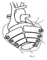
- FIG. 1 schematically shows a human heart 10, which is shown with broken lines and from which the known atria and large vessel 12 and go.
- a cardiac assist device comprising a cup-shaped support member 14 having a closed peripheral side wall 16 and a bottom portion 18.
- the support member 14 is open at the top.
- the corresponding opening bears the reference numeral 20. Through them, the atria and large vessels 12 extend.
- an axial support 22 e.g. a welded or molded cuff, inwards.
- the heart 10 is inserted into the carrier component 14, without being injured, from above through the opening 20 and is enclosed by the carrier component 14.
- the axial holder 22 is preferably designed to be flexible for easier insertion of the heart 10, so it can be stretched outwards during insertion.
- the axial support 22 can be fixed to the pericardial fold or other points.
- a plurality of adjacent chambers 24 are provided on this, which preferably each have their own connection line 26. To improve clarity, only one of the numerous chambers 24 and their associated connection line 26 in FIG. 1 provided with a reference numeral.
- FIG. 8 shows the chambers 24 with their inside flexible, in particular elastic wall 28th
- the chambers 24 are part of a fluid circuit, which in the FIGS. 4 and 5 is shown as an example.
- the chambers 24 can be formed, for example, by gluing or welding a membrane directly to the carrier component 14 on the inside, so that the chambers 24 are bounded on the inside by the membrane and on the outside by the carrier component 14.
- the chambers 24 can of course also be defined on the inside by a separate wall, which is fastened to the carrier component 14.
- the chambers 24 are preferably, but not necessarily, only over a peripheral portion; that is, they do not run closed.
- the left half of the heart 30 and the right half of the heart 32 are assigned their own chambers 24.
- the chambers 24 extend obliquely upward with respect to the axis A emanating from the apex 34, which preferably runs along the cardiac septum.
- the mutually circumferentially opposed chambers 24, which are associated with the heart halves 30, 32 respectively, preferably do not overlap one another in the circumferential direction, so that a strip-shaped, axially extending portion 36 is formed, in which no chambers 24 are provided. Also axially, the chambers 24, as FIG. 1 shows, separated from each other and also spaced from each other.
- the support member 14 is inherently rigid and dimensionally stable. It is made so rigid that it is not appreciably deformed by the pumping heart and the expanding chambers. Because of this inherent rigidity, it is also possible to bring a deformed heart, which due to its deformation has inadequately closing heart valves, in a again at least approximately normal shape. Thus, the natural valve closing function can be improved.
- the chambers 24 are pulsed filled and emptied with pressurized fluid and press at least in a filled state with its inner wall 28 against the heart 10 in order to compress it and to support or take over the pumping function.
- the chambers 24 can be positioned due to the intrinsic stiff support member 14 at any point, without necessarily resulting in a total compression of the heart 10, as in flexible Cuffs is the case.
- the support member 14 has a wall thickness of 1 to 5 mm, which need not be constant.
- FIG. 8 shows, somewhat exaggerated, that the wall thickness to the bottom portion 18 is higher than in the region of the upper edge 38 to which the axial support 22 is attached. Due to the different thicknesses, a different rigidity of the carrier component 14 results, wherein the sections of different stiffness in particular continuously merge into one another. In the region of the upper edge 38, the carrier component 14 preferably has a lower rigidity than in the region of the heart-tip-side bottom portion 18. Thus, the upper edge 38 can be made somewhat softer, which reduces the cardiac load at this point.
- the rigidity of the support member 14 may be different in the axial and / or circumferential direction to be optimally tailored to the heart 10 individually.
- the different inherent rigidity can also be achieved by other measures, for example by different materials which merge into one another, or by the different proportion of reinforcing material which may be embedded in the carrier component. This is based on FIG. 7 later explained in more detail.
- the stiffness is selected according to an embodiment so that during operation of the device, the support member 14 on the outside bulges locally by a maximum of 3 mm, preferably a maximum of 1 mm, as based on FIG. 1 is shown and where X indicates the bulge distance.
- Suitable materials for the support member 14 are various materials, but in particular plastic, e.g. Polyamide, PTFE coated polyamide or PEEK.
- the support member 14 may of course also be made of metal, in particular titanium or nitinol. But composite components made of plastic and metal reinforcements are possible.
- shape memory alloys When using metal, shape memory alloys can bring particular advantages.
- the support member 14 has an upper, softer portion 40 and a lower, stiffer portion 42.
- both regions 40, 42 are dimensionally stable relative to the normal pressure during operation of the device.
- metal reinforcements 44 are completely embedded, for example by encapsulation thereof.
- the metal reinforcements 44 here made of a shape memory alloy, are designed in a lattice-shaped manner in order to improve their embedding in the plastic and to allow a certain degree of flexibility.
- the support member 14 should be inherently rigid. However, at higher loads, for example during a cardiac massage or during a stroke against the thorax, the support member 14 is flexible enough to allow for radial, resilient compression. When not installed, the elasticity is so great that the carrier component 14 can be deformed by at least 75% relative to the unloaded state without plastically deforming or breaking. In FIG. 8 For this purpose, the distance D of adjacent wall sections is shown in the unloaded state and with broken lines when the support member 14 is compressed. This distance D can be reduced to at least 75%, without causing the carrier component 14 to be destroyed. The elasticity of the support member 14 may even go so far that the opposite wall portions touch (see FIG. 8 In this case, of course, by touching it is to be understood that the inner walls of the non-inflated chambers 24 touch each other.
- the flexibility of the carrier component 14 does not have to be present in every section, in particular not in the region of the bottom section 18. It is sufficient if the upper third, in particular the upper half, has the aforementioned elasticity.
- fastenings can also be provided, for example, fastening projections 48 which are attached to the outside of the carrier component 14, in particular integrally formed, and project through small openings in the pericardium 46. From the outside, a closure 50 is placed on the free end of the attachment extension 48 in order to prevent the attachment extension 48 from sliding out.
- This closure 50 is in particular a pushbutton which is attached to a correspondingly shaped end of the Befest Trentsfortsatzes 48 is placed. As in FIG. 3 To see several attachment extensions 48 can be attached anywhere.
- the support member 14 is sutured to the pericardium 46, to the pericardial fold on the aorta or pulmonary ligament.
- a provided on the support member 14, molded thread holder 52 is particularly in the Figures 3 and 8th clearly visible.
- the unit of support member 14 and chambers 24 has on the inside a wall or a coating of PEEK or PTFE or other low-friction coatings / materials.
- a wall or a coating of PEEK or PTFE or other low-friction coatings / materials for this purpose, for example, an additional complete wall, which runs like a bag inside the carrier component 14, can be formed.
- the inside walls 28 can be carried out accordingly.
- the axial height of the support member 14 measured from the apex 34 should be selected so that the upper edge 38 is about 10 to 20 mm below the so-called heart valve plane. Another definition in this context, which is also intended to reduce or eliminate interference with the flaps, is to leave no chambers 24 protruding into the valve plane. The chambers 24 should then also end 10 to 20 mm below the valve plane.
- FIG. 2 gives a better representation of the individual chambers.
- the lowermost chamber 24 ' is made larger volume and covers the bottom portion 18 largely from.
- This chamber 24 ' can be the axial inner height of the unit of support member 14 and chambers 24 vary slightly and adapt to the heart volume.
- the pump function can also be supported via the chamber 24 '.
- FIG. 3 should clarify that the chambers 24 of course do not have to cover the approximately entire inner side of the support member 14. Rather, with regard to the possibly local weakness of the patient's heart, it is much better to provide chambers 24 at individual, few places. Thus, some or many chambers 24 may be provided, of course, preferably the device is executed with numerous chambers 24.
- FIG. 4 is an overview of the entire cardiac assist device to see, in which the unit of support member 14 and chambers is symbolically indicated by three chambers 126, 226 and 336. Of course, more than three chambers 126, 226 or 326 can be integrated into the overall device accordingly.
- Each chamber 126, 226, 326 is in fluid communication with a pressure fluid reservoir 60 via its own multi-way valve 54 to 58, which is only assigned to it. From the pressure fluid reservoir 60, lines 62 to 66 extend to the valves 54 to 58. These lines 62 to 66 are inflow lines. Lines 68 to 72 between the valves 54 to 58 to the chambers 26 to 326 are combined supply and discharge lines.
- outflow lines 74 to 78 extend to a fluid pump 80 which pumps fluid into the reservoir 60.
- the pump 80 preferably operates permanently and generates a permanent pressure in the accumulator 60.
- the accumulator 60 is in fluid communication with an intracorporeal fluid refill tank 84 via a refill tank valve 82.
- the fluid replenishment tank 84 contains fluid (preferably pressurized) that enters the previously discussed fluid circuit via the fluid circuit temporarily opened valve 82 flows when too little fluid is contained in the circuit.
- the refill tank is preferably made of metal (especially titanium), plastic or glass or a sandwich construction of these materials.
- a transcutaneously connectable refill interface 86 may be provided, which is designed in particular as a passive valve and is accessible from the outside, for example via a syringe 88. This can be refilled with lack of fluid in the circuit from the outside fluid.
- the interface 86 may also be coupled directly to the memory 60.
- the coupling of the refill tool can e.g. via a rotation (i.e., screw) or bayonet lock done.
- the refueling tank valve 82 can be activated either via its own control unit 90 or via a central controller 92.
- the controller 90 may also be controlled by extracorporeal transmission and receiver units, for example, to temporarily open the refill tank valve 82. Also, the amount of the inflowing fluid is controlled by the opening time of the refilling tank valve 82.
- the controller 90 or 92 which is responsible for the refilling tank valve 82, is designed so that it automatically controls the refilling tank valve 82 in the event of fluid loss in the fluid circuit. But, as already explained, this control can also be done by extracorporeal.
- a pressure sensor 94 in the memory 60 which is connected to the controller 92, provides information about the pressure in the memory 60.
- the controller 92 described below as a central controller communicates with the pump 80, the individual valves 54 to 58, and optionally the refill tank valve 82 , as well as with Sensors 96 to 100, which are housed in the chambers 126 to 326, in conjunction. This can be used to make statements about the pressure in the chambers 126 to 326.
- Other pressure sensors 102, 104 detect the pressure in the two heart chambers and pressure sensors 106 to 108 in the vein or the aorta.
- the central controller 92 may also be coupled to an ECG sensor 130 and / or to a pacemaker, in particular a two-chamber pacemaker 1 10.
- the pump 80 may be direct or via the central controller 92 be connected to an energy storage 112, in particular a battery.
- this energy store 112 is permanently or temporarily charged externally via a magnetic or electrical transmitter 114 without having to lead through the skin lines.
- the central controller 92 can be controlled externally, also via the transceiver unit 1 16, 1 18 or reprogrammed.
- the outside of the body provided transmitter-receiver unit 1 18 may also be coupled to an Internet interface, in particular via wireless LAN. It is thus possible to connect the patient, so to speak, from home with a doctor, so that he or she can read out the values of the patient and, if necessary, reprogram the central control unit 92.
- the pump 80 which is preferably designed with a brush-release drive, ensures a permanent overpressure in the pressure fluid reservoir 60.
- the central controller 92 individually controls the valves 54 to 58 so that pressure fluid from the reservoir 80 inflates the chambers 126 to 326 in a pulsating manner and thus the heart 10 narrows.
- the chambers 126 to 326 are independently or in groups via the valves 54 to 58 (in accordance with FIG. 4 individually).
- pressure and / or ECG control reverses the valves 54 to 58 so that the chambers 126 to 326 are flow-connected to the pump 80 and are emptied abruptly.
- the heart 10 can expand so again.
- the amount of compression of the heart 10 may be dependent on the pressure or flow values determined by the sensors.
- the device according to the invention can be implemented as a closed circuit which lies completely intracorporeally or which is also partially positioned extracorporeally (for example pump or energy store).
- Another embodiment of the invention provides to operate the device as an open system. This means that the device discharges the compressed air to the outside after the chambers via a line protruding from the body. If present, the outflow valves may still be intracorporeal. The intra- or extracorporeal pump sucks in air from the atmosphere. With broken lines is in FIG. 4 For this purpose, a leading to the atmosphere suction line 200 shown. The lines 74, 76, 78 would not connect to the pump 80 here, but would lead via a manifold 202 to the outside of the body.
- a pressure fluid collection chamber 204 (broken line in FIG. 4 ), into which the lines coming from the individual chambers open.
- the pressure fluid collection chamber serves as a fluid buffer.
- the cardiac assist device is equipped with an emergency sensor that uses the sensors 96 to 100. As soon as the controller 92 detects an excessive pressure drop in one of the chambers 126 to 326, the corresponding valve 54 to 58 is permanently closed so that fluid can no longer flow out via the defective chamber.
- the controller 92 is further designed such that it falls below a predetermined pressure minimum or exceeded Maximum pressure in the accumulator or at increased pulse frequency, the speed of the pump 80 changed.
- the heart 10 supported by the device may become smaller over the years. As a result, the support function of the device may be lower and / or the seat of the support member 14 unit and chambers 126-326 may deteriorate. Once this diminution of the heart 10 is detected, the controller 92 may control the valves 54-58 so that the chambers 126-326 are less completely deflated, that is, they are constantly abutting the heart wall. In addition, or alternatively, previously unused chambers such as those in FIG. 2 shown chamber 24 'filled or filled more.
- the chambers 126 to 326 do not have to be filled at the same time. Rather, it may be advantageous to fill them delayed in time and to empty them again.
- the left chambers 24 are filled in time slightly before the right chambers 24 so that the left half of the heart experiences an external pressure before the right half of the heart.
- the chambers 24 can be filled with a time stagger from the apex 18 so that the uppermost chambers 24 are filled last.
- the staggered inflation process from the lowest to the uppermost chamber 24 is to ensure the so-called lifting function of the heart in the direction of the aorta.
- the pressure in the chambers 24, 126 to 326 or in the halves of the heart also provides information about the function and performance of the heart.
- determined pressure values and pressure curves can be a function evaluation of the heart calculate and possibly three-dimensional represent.
- a healthy heart has less back pressure, so less fluid must be introduced into the chambers 24, 126 to 326. Should the heart recover with respect to its performance, a lower pressure is also generated in the chambers 24, 126 to 326 via the controller 92.
- the size, number, and position, as well as the volume of the chambers 24, 126-326 may vary to tune the device to the disease of the heart and the size of the heart.
- FIG. 5 essentially corresponds to the FIG. 4 so that in the following only the differences have to be addressed.
- the pump 80 in addition to the pump 80 also coupled with her runflat pump 180 is coupled. Once the pump 80 fails, the emergency pump 180 is switched on via the controller 92, which then provides the required pressure in the fluid.
- so-called trigger sensors 120 are also provided, via which a coordination between the cardiac function and the pumping function of the device can take place.
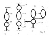
- FIG. 6 shows various other embodiments, as the chambers 24, 126 to 326 are driven.
- a plurality of chambers 24 via a common valve, here a combined inlet and outlet valve 54, driven.
- the support member 14 is specially adapted to the shape of the heart 10 of the patient and manufactured individually. This production takes place as a three-dimensional tailor-made production.
- This purpose by an MRI and / or CT scan method (see FIG. 9 ) Data of the heart which directly or indirectly represent a three-dimensional heart external shape or pericardial external shape. Indirect means that data obtained by MRI or CT will calculate the corresponding data for the 3-D form of the heart (Surface Reconstruction, Sulfate Rendering). This data is input to the controller 124 of a machining center 128 directly or via a data memory 122.
- the machining center 126 is, for example, a center for laser sintering, stereolithography, or the like. Alternatively, of course, it can also be a machining center.
- a support member 14 is selected from a variety of prefabricated support components on the obtained 3-D shape, which requires less post-processing than the others.
- the machining center 128 could be, for example, a milling center over which fine tuning then occurs.
- the machining center 128 may include one or more elements of an injection mold 130 (see FIG. 10 ).
- the carrier component 14 is then poured over this injection mold 130 (see FIG FIG. 10 ), in which a male 132 has been manufactured individually.
- a combination of the individual, individually controllable chambers 24, 126 to 326 with a two-chamber pacemaker system is used for resynchronization of the heart activity.
- the support member 14 may also sit outside the pericardium and also surround it. All the above features are used accordingly in this alternative.
- the method just described is also used for the manufacture of an implant that at least partially replaces or is implanted adjacent to an internal organ or internal organ structure to support the organ.
- This implant is manufactured individually on the basis of data obtained by an imaging process that reproduces the three-dimensional organ shape or the body part replaced by the implant.
- the implant does not replace a hard body part such as a tooth or a bone, but replaces or supports a soft body part inside the body. Accordingly, the contour of a soft body part in the interior of the body is determined by the imaging process in order to be able to manufacture the implant individually.
- the implant is in particular the aorta, of which of course also an aortic section falls (ascending, arch, deszendens), or a heart valve or a diaphragm or the lung supporting it to this adjacent support member.
- the cardiac assist device is preferably a pneumatically operating device, i. the chambers are inflated by gas, especially air.
Description
Die Erfindung betrifft eine Herzunterstützungsvorrichtung und ein Verfahren zu ihrer Steuerung.The invention relates to a cardiac assist device and a method for its control.
Das Krankheitsbild der Herzinsuffizienz (engl.: Heart Failure) beschreibt den Zustand der Unfähigkeit des Herzens, durch ausreichende Pumpkraft den Organismus mit Blut zu versorgen. Es zeichnet sich durch ein klinisches Syndrom bestehend aus Müdigkeit, Kurzatmigkeit und Flüssigkeitsretention aus. Die Ursachen sind vielschichtig und korrelieren oft mit den Lebensgewohnheiten (Risikofaktoren) der Industrienationen. Epidemiologisch lassen die USamerikanischen Zahlen das Ausmaß der Erkrankung erkennen und sind in vollem Umfang auf die sieben wichtigsten Medizin und Gesundheitsmärkte (USA, Frankreich, Deutschland, Italien, Japan, Spanien und England) anwendbar. Generell wird davon ausgegangen, dass weltweit 23 Mio. Menschen an Herzinsuffizienz erkrankt sind und ca. 2 Mio. Neuerkrankungen pro Jahr hinzu kommen.The condition of heart failure describes the condition of the inability of the heart to supply the organism with sufficient pumping power. It is characterized by a clinical syndrome consisting of fatigue, shortness of breath and fluid retention. The causes are complex and often correlate with the habits (risk factors) of the industrial nations. Epidemiologically, the US figures show the extent of the disease and are fully applicable to the seven major medical and healthcare markets (US, France, Germany, Italy, Japan, Spain and England). In general, it is assumed that worldwide 23 million people suffer from heart failure and about 2 million new cases per year are added.
In den USA leiden derzeit 5 Mio. Menschen an Herzinsuffizienz, mit einer jährlichen Neuerkrankungsrate von 550.000. Aufgrund der sich dramatisch entwickelnden Altersstruktur wird sich in den nächsten zehn Jahren die Anzahl der herzinsuffizienten Patienten in jeder Lebensdekade jenseits des 50. Lebensjahres verdoppeln; das heißt, in den USA werden im Jahre 2018 insgesamt 10 Mio. Menschen an dieser Erkrankung leiden und eine entsprechende Therapie in Anspruch nehmen müssen.In the US, there are currently 5 million people suffering from heart failure, with an annual incidence of 550,000. Due to the dramatic age structure, over the next decade, the number of heart failure patients will double in each decade of life beyond the age of 50; In other words, in the USA, a total of 10 million people will suffer from this disease in 2018 and will need to seek appropriate treatment.
Um die Lebenserwartung des Patienten zu erhöhen, gibt es neben der Herztransplantation oder der Implantation intravaskuläre Unterstützungssysteme mit den damit verbundenen Risiken des Schlaganfalles, Blutungen oder Infektionen auch Überlegungen, um das Herz eine Manschette oder einen Sack zu legen, der aufblasbare Kammern aufweist. Diese Kammern werden entsprechend der Herzkontraktion befüllt und entleert, sodass sie von außen gegen das Herz drücken und es beim während der Kontraktion durch aktives Komprimieren oder augmentieren vollständig oder zumindest partiell unterstützen oder sogar die Herztätigkeit übernehmen. Der Sack oder die Manschette sind möglichst flexibel, um sich an die Form des Herzens anpassen zu können. Ein Beispiel für eine solche Herzunterstützungsvorrichtung gibt die
Die Erfindung betrifft eine leistungsfähige Herzunterstützungsvorrichtung gemäß den Ansprüchen. Die erfindungsgemäße Herzunterstützungsvorrichtung umfasst einen intrakorporalen Fluidnachfülltank (84) und ein intrakorporales Nachfülltankventil (82), das bei Fluidverlust im Fluidkreislauf selbsttätig in die offene Stellung gebracht werden kann.The invention relates to a powerful cardiac assist device according to the claims. The cardiac assist device according to the invention comprises an intracorporeal fluid refill tank (84) and an intracorporeal refill tank valve (82) which can be automatically brought into the open position in the event of fluid loss in the fluid circuit.
Die erfindungsgemäße Herzunterstützungsvorrichtung hat ein das Herz umschließendes Trägerbauteil, an dem innenseitig mehrere benachbarte inflatierbare und deflatierbare Kammern vorgesehen sind, über die eine innenseitige Wand einwärts verschiebbar ist, wobei die Kammern über Leitungen mit wenigstens einer Pumpe in Strömungsverbindung stehen. Mehrere zuströmseitige Zuströmventile sind zwischen Pumpe und Kammern angeordnet. Zumindest einzelne Kammern oder Gruppen von Kammern sind eigenen Zuströmventilen zugeordnet, um die Kammern unabhängig einzeln bzw. gruppenweise anzusteuern. Alle Kammern sind vorzugsweise parallel geschaltet, so dass sie einzeln oder in Gruppen ansteuerbar sind. Somit lassen sich auch zeitlich abgestaffelte oder unterschiedliche Druckverläufe realisieren.The cardiac assist device according to the invention has a carrier component enclosing the heart, on which several adjacent inflatable and deflatable chambers are provided on the inside, via which an inside wall can be displaced inward, wherein the chambers are in fluid communication with at least one pump. Several inflow-side inflow valves are arranged between the pump and the chambers. At least individual chambers or groups of chambers are associated with their own inflow valves to separate the chambers individually or to control in groups. All chambers are preferably connected in parallel, so that they can be controlled individually or in groups. Thus, even staggered or different pressure gradients can be realized.
Durch die vorzugsweise 1:1 Zuordnung von Kammern und Zuströmventilen lässt sich die Unterstützung des Herzens mittels der erfindungsgemäßen Vorrichtung sehr exakt vornehmen und die natürliche, teilweise sehr komplexe Pumpbewegung des Herzens nachbilden. Ferner können auch gezielt geschädigte Teilabschnitte des Herzens unterstützt werden. Die vorliegende Erfindung sieht vor, nicht nur ein Zuströmventil für die mehreren Kammern bereitzustellen, sondern eine individuelle Ansteuerung der Kammern zu ermöglichen, was mit einer Vielzahl von Zuströmventilen erreicht wird. Damit kann das erkrankte Herz wesentlich individueller unterstützt werden, und es lässt sich ein auf verschiedene Belastungssituationen hin angepasstes Pumpverhalten erzielen, indem die Kammern unterschiedlich stark, auch temporär versetzt zueinander, befüllt werden. Ferner können einzelne Herzregionen segmental (regional) unterstützt werden. Im Stand der Technik sind keine Ventile vorgesehen, weil die Steuerung über Kolbenpumpen als ausreichend erachtet wurde. Die Erfindung setzt sich deshalb deutlich von diesen einfacheren Systemen ab. Die Kammern sind insbesondere asymmetrisch angeordnet.By preferably 1: 1 allocation of chambers and inflow valves, the support of the heart by means of the device according to the invention can make very accurate and simulate the natural, sometimes very complex pumping movement of the heart. Furthermore, targeted damaged sections of the heart can be supported. The present invention provides not only to provide an inlet valve for the plurality of chambers, but to allow individual control of the chambers, which is achieved with a plurality of inflow valves. Thus, the diseased heart can be much more individually supported, and it can be adapted to different stress situations pumping behavior achieved by the chambers are filled to different degrees, even temporarily offset from each other. Furthermore, individual heart regions can be supported segmentally (regionally). In the prior art, no valves are provided because the control over piston pumps was considered sufficient. The invention therefore clearly sets itself apart from these simpler systems. The chambers are arranged in particular asymmetrically.
Zwischen der Pumpe und den Kammern ist zuströmseitig wenigstens ein Druckspeicher angeordnet, in den die Pumpe Druckfluid einspeist, wobei die Ventile stromabwärts des Druckspeichers angeordnet sind. Durch Vorsehen eines Druckspeichers lässt sich die Pumpe bei geringerer Leistung permanent betreiben, und Druckabfälle werden vermieden. Über den Druckspeicher steht permanent genügend Druck zur Verfügung, um sehr schnell einzelne oder alle Kammern zu inflatieren. Zusätzlich oder alternativ hierzu kann auch stromaufwärts der Pumpe eine Druckfluidsammelkammer vorhanden sein, in die die von den einzelnen Kammern kommenden Leitungen münden. Die Druckfluidsammelkammer dient als Fluidzwischenspeicher.Between the pump and the chambers, at least one pressure accumulator is arranged on the inflow side, into which the pump feeds pressure fluid, wherein the valves are arranged downstream of the pressure accumulator. By providing a pressure accumulator, the pump can be operated continuously at lower power, and pressure drops are avoided. The accumulator permanently has sufficient pressure available to quickly inflate individual or all chambers. Additionally or alternatively, upstream of the pump, a pressure fluid collection chamber may be present, into which open the lines coming from the individual chambers. The pressure fluid collection chamber serves as a fluid buffer.
Eine bevorzugte Ausführungsform sieht vor, dass ein den Druck im Druckspeicher ermittelnder Drucksensor vorgesehen ist. Die über den Drucksensor gewonnen Daten erlauben es, die Pumpe gezielt anzusteuern, wenn ein zu hoher oder zu niedriger Druck im Druckspeicher vorhanden sein sollte. Die Pumpe lässt sich somit energiesparend auf minimaler Drehzahl halten.A preferred embodiment provides that a pressure sensor which determines the pressure in the pressure accumulator is provided. The data obtained via the pressure sensor allow the pump to be specifically controlled if too high or too low a pressure should be present in the pressure accumulator. The pump can thus be kept energy-saving at minimum speed.
Bei Unterschreiten/Überschreiten eines vorgegebenen Druckminimums bzw. Druckmaximums im Druckspeicher wird über die Steuerung die Drehzahl der Pumpe verändert.When falling below a predetermined pressure minimum or maximum pressure in the pressure accumulator, the speed of the pump is changed by the controller.
Wenn von jeder Kammer eine eigene, nur ihr zugeordnete Zu- und Abströmleitung ausgeht, lässt sich auch das Deflatieren individuell für jede Kammer steuern.If each chamber has its own inflow and outflow line assigned to it, deflating can also be controlled individually for each chamber.
Die Kammern sollten unmittelbar mit der Pumpe abströmseitig strömungsverbunden sein, damit ohne wesentliche Strömungsverluste das Fluid sofort wieder über die Pumpe unter Druck gesetzt wird. Damit soll auch die Leitungslänge des Fluidkreislaufes gering gehalten werden.The chambers should be flow-connected directly downstream of the pump, so that the fluid is immediately pressurized again via the pump without significant flow losses. This should also be kept low the line length of the fluid circuit.
Es ist von Vorteil, wenn abströmseitig zwischen den Kammern und der Pumpe Abströmventile vorgesehen sind, über die dann die Zeitdauer, über die die Kammern inflatiert bleiben, veränderbar ist. Darüber hinaus lässt sich so auch das Deflatieren der Kammern zeitlich abstaffeln.It is advantageous if outflow valves are provided between the chambers and the pump, via which then the time duration over which the chambers remain inflated, is variable. In addition, the deflating of the chambers can also be time-graded.
Auch die Abströmventile sollten zur Erzielung einer individuelleren Herzunterstützung einzelnen oder Gruppen von Kammern zugeordnet sein.The outflow valves should be assigned to achieve a more personalized heart support individual or groups of chambers.
Eine platzsparende Ausführungsform der Erfindung sieht vor, dass zumindest ein, vorzugsweise alle je einer einzelnen oder einer Gruppe von Kammern zugeordneten Zuström- und Abströmventile zu je einem Mehrwegventil zusammengefasst sind.A space-saving embodiment of the invention provides that at least one, preferably all, each associated with a single or a group of chambers inflow and outflow valves are combined to form a multi-way valve.
Die kammerseitige Zuströmleitung bildet gemäß einer Ausführungsform abschnittsweise die Abströmleitung. Die Kammern selbst haben folglich nur eine gemeinsame Zu- und Abströmleitung, um den Platzbedarf für die Vorrichtung gering zu halten.The chamber-side inflow line forms the discharge line in sections according to one embodiment. The chambers themselves therefore have only one common supply and discharge line to keep the space required for the device low.
Die erfindungsgemäße Vorrichtung lässt sich als geschlossener Kreislauf ausführen, der komplett intrakorporal liegt, oder der teilweise auch extrakorporal positioniert ist (z.B. Pumpe oder Energiespeicher). Eine weitere Ausführungsform der Erfindung sieht vor, die Vorrichtung als offenes System zu betreiben. Dies bedeutet, dass die Vorrichtung nach den Kammern über eine aus dem Körper herausragende Leitung die Druckluft nach außen ablässt. Falls vorhanden, können die Abströmventile noch intrakorporal liegen. Die intra- oder extrakorporal liegende Pumpe saugt Luft aus der Atmosphäre an.The device according to the invention can be designed as a closed circuit which lies completely intracorporeally or which is also partially positioned extracorporeally (for example pump or energy store). Another embodiment of the invention provides to operate the device as an open system. This means that the device discharges the compressed air to the outside after the chambers via a line protruding from the body. If present, the outflow valves may still be intracorporeal. The intra- or extracorporeal pump sucks in air from the atmosphere.
Eine Steuerung der Ventile und eine damit gekoppelte Notfallsensorik erlauben es, bei Detektion einer Leckage einer Kammer die der defekten Kammer zugeordneten Ventile bleibend zu schließen. Da das Nachfüllen von Druckfluid oder, allgemeiner, von Fluid in den Kreislauf sehr aufwendig ist oder gegebenenfalls nur transkutan erfolgt, sollten auch kleinste Leckagen vermieden werden.Control of the valves and an emergency sensor system coupled thereto make it possible to permanently close the valves associated with the defective chamber when a leakage of a chamber is detected. Since the refilling of pressurized fluid or, more generally, of fluid in the circuit is very expensive or possibly only transcutaneous, even the smallest leaks should be avoided.
Weil der Ausfall einer Pumpe bei einem stark geschwächten Herz lebensbedrohlich sein könnte, sieht die Erfindung gemäß einer bevorzugten Ausführungsform vor, dass eine zusätzlich vorhandene Notfallpumpe aktiviert wird, sobald eine Steuerung der Pumpen die Detektion eines Pumpendefekts erkennt.Because the failure of a pump in a severely weakened heart could be life-threatening, the invention according to a preferred embodiment provides that an additional emergency pump is activated as soon as a control of the pumps detects the detection of a pumping defect.
Mit einer Steuerung für die Ventile und/oder die Pumpe gekoppelte Durchfluss oder Drucksensoren erlauben es, Druck in einzelnen oder Gruppen von Kammern zu ermitteln. Über diese Werte lässt sich der herzustellende, gewünschte Kammerdruck steuern oder sogar regeln. Ebenso lassen sich Druckabfälle zum Beispiel bei einer Leckage schnell ermitteln. Diese Idee lässt sich, verallgemeinert, sogar auf eine Herzunterstützungsvorrichtung nach dem Oberbegriff des Anspruchs 1 anwenden.With a controller for the valves and / or the pump coupled flow or pressure sensors allow to determine pressure in individual or groups of chambers. These values can be used to control or even regulate the desired chamber pressure to be produced. Likewise, pressure drops can be quickly determined, for example, in the event of a leak. This idea can be generalized, even apply to a cardiac assist device according to the preamble of claim 1.
Herzseitige Drucksensoren sollten gemäß der bevorzugten Ausführungsform ebenfalls vorgesehen sein. Sie sind mit einer Steuerung für Ventile und/oder die Pumpe gekoppelt und lassen einen Rückschluss über die erfolgte und die notwendige Unterstützung des Herzens durch die erfindungsgemäße Vorrichtung zu. Über die Sensoren am Herzen kann darüber hinaus auch die Herzfrequenz zur Frequenz der Unterstützungsvorrichtung angepasst werden. Dies kann aber zusätzlich oder alternativ auch durch ein EKG oder durch Koppelung mit einem Herzschrittmacher, insbesondere einem Zwei-Kammer-Herzschrittmacher realisiert werden. Diese Idee lässt sich, verallgemeinert, sogar auf eine Herzunterstützungsvorrichtung nach dem Oberbegriff des Anspruchs 1 anwenden.Cardiac pressure sensors should also be provided according to the preferred embodiment. They are coupled with a controller for valves and / or the pump and allow a conclusion about the done and the necessary support of the heart by the device according to the invention. In addition, the heart rate can be adjusted to the frequency of the support device via the sensors on the heart. However, this can additionally or alternatively also be realized by an ECG or by coupling with a pacemaker, in particular a two-chamber pacemaker. This idea can be generalized even apply to a cardiac assist device according to the preamble of claim 1.
Ein intrakorporaler Nachfülltank für Fluid, der über ein Nachfülltankventil mit dem Fluidkreislauf koppelbar ist, ermöglicht das Zuströmen von Fluid, insbesondere Druckfluid in den Fluidkreislauf, wenn zu wenig Fluid vorhanden sein sollte.An intracorporeal refill tank for fluid, which can be coupled to the fluid circuit via a refill tank valve, allows inflow of fluid, in particular pressurized fluid, into the fluid circuit if too little fluid is present.
Der Nachfülltank ist vorzugsweise aus Metall (insbesondere Titan), Kunststoff oder Glas oder einer Sandwichkonstruktion aus diesen Materialien.The refill tank is preferably made of metal (especially titanium), plastic or glass or a sandwich construction of these materials.
Auch das Nachfiilltankventil ist mit einer (insbesondere zentralen) Steuerung gekoppelt oder auch extrakorporal steuerbar. Beispielsweise lassen sich Daten wie der Maximaldruck in der Kammer von extrakorporal auslesen, sodass Rückschlüsse über die sich im Fluidkreislauf befindliche Fluidmenge gezogen werden können. Dann lässt sich beispielsweise durch den behandelnden Arzt die erforderliche fehlende Fluidmenge erhöhen. Dies erfolgt bevorzugt von extrakorporal über Sender-Empfänger-Einheiten, über die das Nachfülltankventil kurzzeitig geöffnet wird.The Nachfiilltankventil is coupled with a (especially central) control or extracorporeal controllable. For example, data such as the maximum pressure in the chamber can be read by extracorporeal, so that conclusions about the amount of fluid in the fluid circuit can be drawn. Then, for example, by the attending physician can increase the required amount of fluid missing. This is preferably done by extracorporeal transmitter-receiver units over which the refill tank valve is opened briefly.
Dieses Nachfüllen erfolgt durch eine Steuerung vollautomatisch, indem bei Detektion von Fluidverlust selbsttätig das Nachfülltankventil in die offene Stellung angesteuert wird.This refilling is done fully automatically by a control by automatically the refilling tank valve is actuated in the open position upon detection of fluid loss.
Es kann auch eine transkutan anschließbare Nachfüllstelle, insbesondere als passives Ventil ausgebildet, vorhanden sein, wobei die Ankoppelung des Nachfüllwerkzeugs z.B. über einen Schraub- oder Bajonettverschluss erfolgen kann.There may also be a transcutaneously connectable refill, especially designed as a passive valve, wherein the coupling of the refill tool e.g. can be done via a screw or bayonet lock.
Eine zentrale, subkutane Steuerung für die Pumpe und die Ventile kann einen Empfänger aufweisen sowie über den Empfänger umprogrammierbar ausgebildet sein. Somit lässt sich beispielsweise über einen geänderten Krankheitsverlauf die Arbeitsweise der erfindungsgemäßen Vorrichtung ändern. Wenn die entsprechende Steuerung auch einen Sender zum Auslesen von Daten besitzt, kann man von außen die Arbeitsweise der Herzunterstützungsvörrichtung oder auch, über die entsprechenden Sensoren, die Leistungsfähigkeit des Herzens ermitteln.A central, subcutaneous control for the pump and the valves may have a receiver and be reprogrammable via the receiver. Thus, for example, the method of operation of the device according to the invention can be changed by changing the course of the disease. If the corresponding controller also has a transmitter for reading out data, it is possible to determine from the outside the mode of operation of the cardiac assistance device or, via the corresponding sensors, the performance of the heart.
Eine extrakorporale, mit der subkutanen Steuerung kabellos gekoppelte Steuereinheit dient dazu, die Daten von der Vorrichtung abzugreifen und weiterzugeben. Eine Internetschnittstelle ermöglicht es, die Daten an einen zu behandelnden Arzt weiterzuleiten, möglicherweise sogar "live". Der Herzpatient muss also nicht den Arzt persönlich konsultieren, er kann sich mit dem Arzt verbinden. Der Arzt hat möglicherweise den Vorteil, dass Daten über einen längeren Zeitraum aufgenommen und an ihn weitergeleitet werden. Dies ermöglicht eine genauere Diagnose des Gesundheitszustandes sowie der Kontrolle der Arbeitsweise der erfindungsgemäßen Vorrichtung.An extracorporeal, wirelessly coupled to the subcutaneous control unit is used to tap the data from the device and pass. An Internet interface allows the data to be forwarded to a doctor to be treated, possibly even "live". The heart patient does not have to consult the doctor personally, he can connect with the doctor. The doctor may have the advantage of receiving and transmitting data over a longer period of time. This allows a more accurate diagnosis of the state of health and the control of the operation of the device according to the invention.
Ein erkranktes Herz kann sich auch im Lauf der Zeit verkleinern. Dies würde bedeuten, dass die Herzunterstützungsvorrichtung zu groß für das Herz wird oder nicht mehr optimal an es angepasst ist. Über stetig reduzierten Kammerdruck und/oder Blutdruck kann auf eine solche Verkleinerung des Herzens geschlossen werden. Die Daten werden über Drucksensoren zur Bestimmung des Kammerdrucks und/oder des Blutdrucks an die zentrale Steuerung für die Pumpe und für die Ventile geleitet, die die Daten auswertet. Vor allem die Variante, dass Blutdruck und Kammerdruck gemessen werden, ist besonders vorteilhaft. Die Ventile werden im Falle einer detektierten Herzverkleinerung von der Steuerung so betätigt, dass die Kammern weniger vollständig entleert und/oder bislang nicht benutzte Kämmern befüllt werden. Die Unterstützungsvorrichtung wird damit auf das sich verkleinernde Herz abgestimmt. Diese Idee ist bevorzugt an die Parallelschaltung der Kammern gekoppelt.A diseased heart can also become smaller in the course of time. This would mean that the cardiac assist device becomes too large for the heart or is no longer optimally adapted to it. Over constantly reduced chamber pressure and / or blood pressure can be concluded on such a diminution of the heart become. The data is sent via pressure sensors to determine the chamber pressure and / or the blood pressure to the central controller for the pump and for the valves, which analyzes the data. Especially the variant that blood pressure and chamber pressure are measured is particularly advantageous. The valves are operated in the event of a detected cardiac reduction by the controller so that the chambers are less completely emptied and / or previously unused combs filled. The support device is thus tuned to the decreasing heart. This idea is preferably coupled to the parallel connection of the chambers.
Eine Synchronisation der Vorrichtung mit dem Herzen kann insbesondere durch Koppelung der zentralen Steuerung für die Pumpe und für die Ventile mit einem Herzschrittmacher, insbesondere einem Zwei-Kammer-Herzschrittmacher, erreicht werden.A synchronization of the device with the heart can be achieved in particular by coupling the central control for the pump and for the valves with a pacemaker, in particular a two-chamber pacemaker.
Auch oder zusätzlich könnte diese zentrale Steuerung für die Pumpe und die Ventile mit einem EKG gekoppelt sein.Also or additionally, this central controller for the pump and the valves could be coupled to an ECG.
Diese beiden Optionen dienen vor allem der Resynchronisation der Herztätigkeit.These two options are mainly used for resynchronization of the heart activity.
Im Gegensatz zum Stand der Technik weist die erfindungsgemäße Herzunterstützungsvorrichtung ein eigensteifes und kein hochflexibles Trägerbauteil auf. Das Trägerbauteil gibt im Betrieb im Wesentlichen nicht nach, sodass sich die Kammern am Trägerbauteil abstützen können und nicht, wie bei einer flexiblen Manschette, der Innenquerschnitt der Manschette lediglich verringert wird. Durch das steife Trägerbauteil kann die Vorrichtung lokal gezielt gegen die Herzwand drücken.In contrast to the prior art, the cardiac assist device according to the invention has an intrinsically stiff and not highly flexible support component. During operation, the carrier component essentially does not yield, so that the chambers can be supported on the carrier component and not, as in a flexible sleeve, the internal cross section of the sleeve only reduced. Due to the rigid carrier component, the device can press local targeted against the heart wall.
Die Herzunterstützungsvorrichtung ist gemäß der bevorzugten Ausführungsform eine pneumatisch arbeitende Vorrichtung, d.h. die Kammern werden über Gas, insbesondere Luft inflatiert.The cardiac assist device according to the preferred embodiment is a pneumatically operating device, ie the chambers are inflated via gas, in particular air.
Darüber hinaus wird auch ein Verfahren zum Steuern einer erfindungsgemäßen Herzunterstützungsvorrichtung, die mit zumindest einer mit den Ventilen gekoppelten Steuerung versehen ist, offenbart. Diese Steuerung steuert die Ventile gruppenweise oder einzeln individuell an. Hierdurch ist es möglich, die natürliche Pumpbewegung des Herzens nachzubilden. Dazu kann es vorteilhaft sein, wenn die Kammern zeitlich versetzt zueinander befüllt/entleert werden.In addition, a method for controlling a cardiac assist device according to the invention, which is provided with at least one controller coupled to the valves, is also disclosed. This control controls the valves in groups or individually individually. This makes it possible to replicate the natural pumping motion of the heart. For this purpose, it may be advantageous if the chambers are filled / emptied in time with respect to one another.
Hierzu kann es gemäß der bevorzugten Ausführungsform vorteilhaft sein, zuerst die unteren Kammern zu befüllen, indem die zugeordneten Zulaufventile zuerst geöffnet werden. Zeitlich verzögert hierzu werden dann die weiter oben liegenden Kammern inflatiert. Auf diese Weise lässt sich die sogenannte Hebefunktion des Herzens in Richtung Aorta unterstützen.For this purpose, it may be advantageous according to the preferred embodiment, first to fill the lower chambers by the associated inlet valves are opened first. Delayed in time then the chambers located further up are inflated. In this way, the so-called lifting function of the heart can be supported in the direction of the aorta.
Die Drehzahl der Pumpe sollte in Abhängigkeit von durch Durchflusssensoren oder Drucksensoren im Fluidkreislauf ermittelten Werten und/oder in Abhängigkeit von EKG-Werten bei Überschreiten oder Unterschreiten von vorgegebenen Werten verändert werden.The speed of the pump should be changed depending on values determined by flow sensors or pressure sensors in the fluid circuit and / or depending on ECG values when exceeding or falling below given values.
Zu betonen ist auch, dass generell die Druckwerte auch über Durchflusssensoren detektierbar sind.It should also be emphasized that in general the pressure values can also be detected via flow sensors.
Die bevorzugte Ausführungsform sieht zwar vor, dass die Herzunterstützungsvorrichtung mit einem becherförmigen Trägerbauteil, in den das Herz eingesetzt wird, ausgestattet ist und das Trägerbauteil im Perikard liegt. Alternativ hierzu kann das becherförmige Trägerbauteil aber auch außen um das Perikard herum angeordnet sein.Although the preferred embodiment provides that the cardiac assist device is equipped with a cup-shaped carrier component into which the heart is inserted, and the carrier component is located in the pericardium. Alternatively, however, the cup-shaped carrier component can also be arranged outside around the pericardium.
Weitere Merkmale und Vorteile der Erfindung ergeben sich aus der nachfolgenden Beschreibung und aus den nachfolgenden Zeichnungen, auf die Bezug genommen wird. In den Zeichnungen zeigen:
-
Figur 1 eine schematische Ansicht der eingesetzten Herzunterstützungsvorrichtung, -
Figur 2 die Herzunterstützungsvorrichtung nachFigur 1 mit entferntem Trägerbauteil, -
Figur 3 die Herzunterstützungsvorrichtung nach der Erfindung in einer weiteren Ausführungsform, -
Figur 4 eine schematische Darstellung der Herzunterstützungsvorrichtung nach den vorhergehenden Figuren samt Steuerung und Pumpe, -
Figur 5 eine schematische Ansicht einer gegenüberFigur 4 leicht modifizierten Herzunterstützungsvorrichtung, -
Figuren 6a bis 6c schematische Ansichten der bei der erfindungsgemäßen Vorrichtung einsetzbaren Ventilschaltungen, -
Figur 7 eine schematische Ansicht eines Teils der Herzunterstützungsvorrichtung, -
Figur 8 eine Schnittansicht durch die Einheit aus Trägerbauteil und Kammern gemäß einer anderen Ausführungsform, -
Figur 9 eine schematische Darstellung, die die Herstellung des Trägerbauteils der erfindungsgemäßen Vorrichtung erläutert, und -
Figur 10
-
FIG. 1 a schematic view of the inserted cardiac assist device, -
FIG. 2 the cardiac assist deviceFIG. 1 with removed carrier component, -
FIG. 3 the cardiac assist device according to the invention in a further embodiment, -
FIG. 4 a schematic representation of the cardiac assist device according to the preceding figures, including control and pump, -
FIG. 5 a schematic view of one oppositeFIG. 4 slightly modified cardiac assist device, -
FIGS. 6a to 6c schematic views of the usable in the inventive device valve circuits, -
FIG. 7 a schematic view of a part of the cardiac assist device, -
FIG. 8 a sectional view through the unit of support member and chambers according to another embodiment, -
FIG. 9 a schematic representation illustrating the preparation of the support member of the device according to the invention, and -
FIG. 10 a schematic sectional view through an injection mold for the preparation of the support member of the cardiac assist device according to the invention.
Ein insuffizientes Herz kann seine Pumpfunktion nur unzureichend oder überhaupt nicht mehr ausführen. Zur Unterstützung der Pumpfunktion des Herzens 10 ist eine Herzunterstützungsvorrichtung vorhanden, die ein becherförmiges Trägerbauteil 14 mit einer geschlossen umlaufenden Seitenwand 16 und einem Bodenabschnitt 18 aufweist. Das Trägerbauteil 14 ist nach oben offen. Die entsprechende Öffnung trägt das Bezugszeichen 20. Durch sie hindurch erstrecken sich die Vorhöfe und großen Gefäße 12.An insufficient heart can not perform its pumping function adequately or not at all. To support the pumping function of the
Am oberen Rand 38 des Trägerbauteils 14 verläuft eine axiale Halterung 22, z.B. eine angeschweißte oder angeformte Manschette, einwärts. Das Herz 10 ist in das Trägerbauteil 14, ohne dabei verletzt zu werden, von oben durch die Öffnung 20 eingesetzt und wird vom Trägerbauteil 14 umschlossen. Die axiale Halterung 22 ist zum leichteren Einführen des Herzens 10 vorzugsweise flexibel ausgeführt, kann also beim Einsetzen nach außen gedehnt werden. Zur verbesserten axialen Fixierung lässt sich die axiale Halterung 22 an der Perikardumschlagfalte oder anderen Punkten fixieren.At the
Auf der Innenseite des Trägerbauteils 14 sind an diesem mehrere benachbarte Kammern 24 vorgesehen, die vorzugsweise jeweils eine eigene Anschlussleitung 26 besitzen. Zur Verbesserung der Übersichtlichkeit ist nur eine der zahlreichen Kammern 24 und ihre zugeordnete Anschlussleitung 26 in
Die Kammern 24 sind Teil eines Fluidkreislaufes, der in den
Die Kammern 24 können beispielsweise dadurch gebildet werden, dass eine Membran unmittelbar an das Trägerbauteil 14 innenseitig aufgeklebt oder aufgeschweißt wird, sodass die Kammern 24 innenseitig von der Membran und außenseitig durch das Trägerbauteil 14 begrenzt werden.The
Alternativ hierzu können die Kammern 24 natürlich auch innenseitig durch eine eigene Wand definiert werden, welche am Trägerbauteil 14 befestigt wird.Alternatively, the
Wie in
Die einander umfangsmäßig gegenüberliegenden Kammern 24, die den Herzhälften 30, 32 jeweils zugeordnet sind, überlappen einander vorzugsweise in Umfangsrichtung nicht, sodass ein streifenförmiger, axial verlaufender Abschnitt 36 entsteht, in dem keine Kammern 24 vorgesehen sind. Auch axial sind die Kammern 24, wie
Das Trägerbauteil 14 ist eigensteif und formstabil. Es wird so steif ausgebildet, dass es durch das pumpende Herz und die sich ausdehnenden Kammern nicht erwähnenswert deformiert wird. Aufgrund dieser Eigensteifigkeit ist es auch möglich, ein deformiertes Herz, das aufgrund seiner Deformation unzureichend schließende Herzklappen besitzt, in eine wieder zumindest annähernd normale Form zu bringen. Damit kann die natürliche Ventilschließfunktion verbessert werden.The
Die Kammern 24 werden pulsierend mit Druckfluid befüllt und geleert und drücken zumindest in befülltem Zustand mit ihrer innenliegenden Wand 28 gegen das Herz 10, um es zu komprimieren und die Pumpfunktion zu unterstützen oder zu übernehmen.The
Die Abstützung bei der Kompression des Herzens 10 erfolgt über das eigensteife, stabile Trägerbauteil 14. Die Kammern 24 können aufgrund des eigensteifen Trägerbauteils 14 an jeder beliebigen Stelle positioniert werden, ohne dass es damit zwangsläufig zu einer Gesamtkompression des Herzens 10 kommt, wie dies bei flexiblen Manschetten der Fall ist.The support in the compression of the
Das Trägerbauteil 14 hat eine Wanddicke von 1 bis 5 mm, die nicht konstant sein muss.The
Die Steifigkeit des Trägerbauteils 14 kann in axialer und/oder Umfangsrichtung unterschiedlich sein, um optimal auf das Herz 10 individuell abgestimmt zu sein.The rigidity of the
Die unterschiedliche Eigensteifigkeit lässt sich auch durch andere Maßnahmen erreichen, beispielsweise durch unterschiedliche Materialien, die ineinander übergehen, oder durch den unterschiedlichen Anteil an Verstärkungsmaterial, welches im Trägerbauteil eingebettet sein kann. Dies wird anhand von
Die Steifigkeit ist gemäß einer Ausführungsform so gewählt, dass während des Betriebes der Vorrichtung das Trägerbauteil 14 außenseitig um maximal 3 mm, vorzugsweise maximal 1 mm lokal ausbaucht, wie anhand von
Als Herstellungsmaterialien für das Trägerbauteil 14 kommen verschiedene Werkstoffe infrage, insbesondere jedoch Kunststoff, z.B. Polyamid, PTFE beschichtetes Polyamid oder PEEK.Suitable materials for the
Alternativ hierzu kann das Trägerbauteil 14 natürlich auch aus Metall, insbesondere Titan oder Nitinol, bestehen. Aber auch Verbundbauteile aus Kunststoff und Metallverstärkungen sind möglich.Alternatively, the
Beim Einsatz von Metall können Formgedächtnislegierungen besondere Vorteile bringen.When using metal, shape memory alloys can bring particular advantages.
In
Vorzugsweise sind beide Bereiche 40, 42 formstabil bezogen auf den normalen Druck während des Betriebs der Vorrichtung. Im Kunststoff des Trägerbauteils 14 sind Metallverstärkungen 44 vollständig eingebettet, zum Beispiel durch Umspritzen derselben. Die Metallverstärkungen 44, hier aus einer Formgedächtnislegierung, sind gitterförmig ausgeführt, um ihre Einbettung im Kunststoff zu verbessern und eine gewisse Flexibilität zu ermöglichen.Preferably, both
Im Bereich 40 ist flächenbezogen weniger Verstärkungsmaterial vorhanden, das heißt weniger Metallverstärkungen, um den Bereich 40 weicher zu gestalten als den darunter liegenden Bereich 42.In
Für die normale Belastung während des Betriebes sollte, wie mehrfach erwähnt, das Trägerbauteil 14 eigensteif sein. Bei höheren Belastungen jedoch, zum Beispiel bei einer Herzmassage oder bei einem Schlag gegen den Brustkorb, ist das Trägerbauteil 14 flexibel genug, um ein radiales, elastisches Zusammendrücken zu ermöglichen. Im nicht eingebauten Zustand ist die Elastizität so groß, dass sich das Trägerbauteil 14, ohne sich plastisch zu verformen oder zu brechen, um mindestens 75 % gegenüber dem unbelasteten Zustand deformieren lässt. In
Natürlich muss die Flexibilität des Trägerbauteils 14 nicht in jedem Abschnitt, insbesondere nicht im Bereich des Bodenabschnitts 18 vorhanden sein. Es reicht aus, wenn das obere Drittel, insbesondere die obere Hälfte, die zuvor erwähnte Elastizität besitzt.Of course, the flexibility of the
Zur Lagesicherung des Trägerbauteils 14 im Körper kann dieses in den Herzbeutel 46 (siehe
Zusätzlich lassen sich auch noch Befestigungen vorsehen, beispielsweise an der Außenseite des Trägerbauteils 14 angebrachte, insbesondere angeformte Befestigungsfortsätze 48, welche durch kleine Öffnungen im Herzbeutel 46 hindurchragen. Von außen wird ein Verschluss 50 auf das freie Ende des Befestigungsfortsatzes 48 aufgesetzt, um ein Herausgleiten des Befestigungsfortsatzes 48 zu verhindern. Dieser Verschluss 50 ist insbesondere ein Druckknopf, der an einem entsprechend geformten Ende des Befestigungsfortsatzes 48 aufgesetzt wird. Wie in
Alternativ oder zusätzlich hierzu wird das Trägerbauteil 14 am Herzbeutel 46, an der Perikardumschlagfalte an der Aorta oder am Ligamentum pulmonale angenäht. Eine am Trägerbauteil 14 vorgesehene, angeformte Fadenhalterung 52 ist insbesondere in den
Um die Reibung auf der Herzaußenseite zu reduzieren, besitzt die Einheit aus Trägerbauteil 14 und Kammern 24 innenseitig eine Wandung oder eine Beschichtung aus PEEK oder PTFE oder anderen friktionsarmen Beschichtungen/Materialien. Hierzu lässt sich beispielsweise eine zusätzliche komplette Wand, die wie ein Beutel innerhalb des Trägerbauteils 14 verläuft, ausbilden. Optional lassen sich aber auch die innenseitigen Wände 28 entsprechend ausführen.In order to reduce the friction on the outside of the heart, the unit of
Die axiale Höhe des Trägerbauteils 14 von der Herzspitze 34 aus gemessen sollte so gewählt sein, dass der obere Rand 38 etwa 10 bis 20 mm unterhalb der sogenannten Herzklappenebene liegt. Eine andere Definition in diesem Zusammenhang, die ebenfalls eine Beeinflussung der Klappen reduzieren oder ausschließen soll, besteht darin, keine Kammern 24 bis in die Klappenebene ragen zu lassen. Die Kammern 24 sollten dann ebenfalls 10 bis 20 mm unterhalb der Klappenebene enden.The axial height of the
In
Von den Ventilen 54 bis 58, die als kombinierte Zuström- und Abströmventile dienen, verlaufen Abströmleitungen 74 bis 78 zu einer Fluidpumpe 80, die Fluid in den Speicher 60 pumpt.Of the
Natürlich können anstatt der kombinierten Zu- und Abströmleitungen 68 bis 72 auch separate Zu- und Abströmleitungen zu und von den Kammern 126 bis 326 weggehen.Of course, instead of the combined supply and
Die Pumpe 80 arbeitet vorzugsweise permanent und erzeugt einen permanenten Druck im Speicher 60. Der Speicher 60 wiederum steht über ein Nachfülltankventil 82 mit einem intrakorporalen Fluidnachfülltank 84 in Strömungsverbindung. Der Fluidnachfülltank 84 enthält Fluid (vorzugsweise unter Druck stehend), das in den zuvor erläuterten Fluidkreislauf über das temporär geöffnete Ventil 82 zuströmt, wenn zu wenig Fluid im Kreislauf enthalten ist.The
Der Nachfülltank ist vorzugsweise aus Metall (insbesondere Titan), Kunststoff oder Glas oder einer Sandwichkonstruktion aus diesen Materialien.The refill tank is preferably made of metal (especially titanium), plastic or glass or a sandwich construction of these materials.
Zusätzlich zu dem Fluidnachfülltank 84 kann eine transkutan anschließbare Nachfüllschnittstelle 86 vorgesehen sein, die insbesondere als passives Ventil ausgebildet ist und zum Beispiel über eine Spritze 88 von außen zugänglich ist. Hierüber kann bei mangelndem Fluid im Kreislauf von außen Fluid nachgefüllt werden. Die Schnittstelle 86 kann auch unmittelbar am Speicher 60 angekoppelt sein.In addition to the
Die Ankoppelung des Nachfüllwerkzeugs (hier Spritze) kann z.B. über einen Dreh(d.h. Schraub-) oder Bajonettverschluss erfolgen.The coupling of the refill tool (here syringe) can e.g. via a rotation (i.e., screw) or bayonet lock done.
Das Nachfülltankventil 82 ist entweder über eine eigene Steuerung 90 oder über eine zentrale Steuerung 92 ansteuerbar. Die Steuerung 90 kann beispielsweise auch von extrakorporal über Senderund Empfänger-Einheiten angesteuert werden, um das Nachfülltankventil 82 temporär zu öffnen. Auch die Menge des zuströmenden Fluids wird durch die Öffnungszeit des Nachfülltankventil 82 gesteuert.The
Die Steuerung 90 oder 92, die für das Nachfülltankventil 82 zuständig ist, ist so ausgebildet, dass sie bei Fluidverlust im Fluidkreislauf selbsttätig das Nachfülltankventil 82 ansteuert. Aber, wie bereits erläutert, dieses Steuern kann auch von extrakorporal erfolgen.The
Ein Drucksensor 94 im Speicher 60, der mit der Steuerung 92 verbunden ist, gibt Auskunft über den Druck im Speicher 60. Die im Folgenden als zentrale Steuerung beschriebene Steuerung 92 steht mit der Pumpe 80, den einzelnen Ventilen 54 bis 58, gegebenenfalls dem Nachfülltankventil 82, sowie mit Sensoren 96 bis 100, die in den Kammern 126 bis 326 untergebracht sind, in Verbindung. Hierüber lassen sich Aussagen über den Druck in den Kammern 126 bis 326 machen. Weitere Drucksensoren 102, 104 erfassen den Druck in den beiden Herzkammern sowie Drucksensoren 106 bis 108 in der Vene bzw. der Aorta.A
Zusätzlich oder alternativ zu den Drucksensoren 102 bis 104 kann die zentrale Steuerung 92 auch mit einem EKG-Sensor 130 gekoppelt sein und/oder mit einem Herzschrittmacher, insbesondere einem Zwei-Kammer-Herzschrittmacher 1 10. Die Pumpe 80 kann direkt oder über die zentrale Steuerung 92 mit einem Energiespeicher 112, insbesondere einem Akku, verbunden sein. Dieser Energiespeicher 112 wird insbesondere, ohne durch die Haut Leitungen führen zu müssen, von außen über einen magnetischen oder elektrischen Sender 114 permanent oder temporär aufgeladen. Die zentrale Steuerung 92 kann von außen, ebenfalls über Sender-Empfängereinheit 1 16, 1 18 kontrolliert werden oder auch umprogrammiert werden. Darüber hinaus kann die außerhalb des Körpers vorgesehene Sender-Empfängereinheit 1 18 auch mit einer Internetschnittstelle, insbesondere über Wireless-LAN, gekoppelt sein. So ist es möglich, den Patienten sozusagen von zuhause aus mit einem Arzt zu verbinden, sodass dieser die Werte des Patienten auslesen und gegebenenfalls die zentrale Steuerung 92 umprogrammieren kann.In addition or as an alternative to the
Im Betrieb sorgt die vorzugsweise mit einem bürstenlösen Antrieb ausgeführte Pumpe 80 für einen permanenten Überdruck im Druckfluidspeicher 60. Die zentrale Steuerung 92 steuert die Ventile 54 bis 58 einzeln an, sodass Druckfluid aus dem Speicher 80 die Kammern 126 bis 326 pulsierend aufbläst und damit das Herz 10 verengt. Die Kammern 126 bis 326 werden unabhängig einzeln oder gruppenweise über die Ventile 54 bis 58 (gemäß
Das Ausmaß der Kompression des Herzens 10 kann von den durch die Sensoren ermittelten Druck- oder Strömungswerten abhängig sein.The amount of compression of the
Die erfindungsgemäße Vorrichtung lässt sich, wie gezeigt, als geschlossener Kreislauf ausführen, der komplett intrakorporal liegt, oder der teilweise auch extrakorporal positioniert ist (z.B. Pumpe oder Energiespeicher).As shown, the device according to the invention can be implemented as a closed circuit which lies completely intracorporeally or which is also partially positioned extracorporeally (for example pump or energy store).
Eine weitere Ausführungsform der Erfindung sieht vor, die Vorrichtung als offenes System zu betreiben. Dies bedeutet, dass die Vorrichtung nach den Kammern über eine aus dem Körper herausragende Leitung die Druckluft nach außen ablässt. Falls vorhanden, können die Abströmventile noch intrakorporal liegen. Die intra- oder extrakorporal liegende Pumpe saugt Luft aus der Atmosphäre an. Mit unterbrochenen Linien ist in
Zusätzlich oder alternativ zum Druckspeicher 60 kann auch stromaufwärts der Pumpe eine Druckfluidsammelkammer 204 (unterbrochene Linie in
Die Herzunterstützungsvorrichtung ist mit einer Notfallsensorik ausgestattet, die die Sensoren 96 bis 100 nutzt. Sobald die Steuerung 92 einen übermäßigen Druckabfall in einer der Kammern 126 bis 326 detektiert, wird das entsprechende Ventil 54 bis 58 permanent geschlossen, sodass über die defekte Kammer kein Fluid mehr ausströmen kann.The cardiac assist device is equipped with an emergency sensor that uses the
Die Steuerung 92 ist ferner so ausgeführt, dass sie bei Unterschreiten/Überschreiten eines vorgegebenen Druckminimums bzw. Druckmaximums im Druckspeicher oder bei erhöhter Pulsfrequenz die Drehzahl der Pumpe 80 verändert.The
Das durch die Vorrichtung unterstützte Herz 10 kann unter Umständen im Laufe der Jahre kleiner werden. Dadurch ist die Unterstützungsfunktion der Vorrichtung möglicherweise geringer und/oder der Sitz der Einheit aus Trägerbauteil 14 und Kammern 126 bis 326 kann sich verschlechtern. Sobald dieses Verkleinern des Herzens 10 detektiert wird, kann die Steuerung 92 die Ventile 54 bis 58 so ansteuern, dass die Kammern 126 bis 326 weniger vollständig entleert werden, das heißt, dass sie stetig an der Herzwand anliegen. Zudem oder alternativ hierzu können bislang nicht benutzte Kammern wie beispielsweise die in
Eine Möglichkeit, um ein sich verkleinerndes Herz zu detektieren, besteht darin, dass dies aus einem stetig reduzierten Kammerdruck und/oder Blutdruck rückgeschlossen wird. Die Kammern 126 bis 326 müssen nicht gleichzeitig befüllt werden. Vielmehr ist es gegebenenfalls vorteilhaft, sie zeitlich verzögert zu befüllen und wieder zu entleeren. So können beispielsweise die (mit Bezug auf
Ferner ist es möglich, die Kammern 24 von der Herzspitze 18 aus zeitlich etwas gestaffelt zu befüllen, sodass die obersten Kammern 24 zuletzt befüllt werden. Der zeitlich gestaffelte Aufblasvorgang von der untersten bis zur obersten Kammer 24 soll die sogenannte Hebefunktion des Herzens in Richtung Aorta sicherstellen.Furthermore, it is possible for the
Der Druck in den Kammern 24, 126 bis 326 oder in den Herzhälften gibt auch eine Aussage über die Funktion und die Leistungsfähigkeit des Herzens. Durch über Drucksensoren ermittelte Druckwerte und über Druckverläufe lässt sich eine Funktionsevaluation des Herzens errechnen und gegebenenfalls dreidimensional darstellen. Ein gesundes Herz hat weniger Gegendruck, sodass auch weniger Fluid in die Kammern 24, 126 bis 326 eingeleitet werden muss. Sollte sich das Herz bezüglich seiner Leistungsfähigkeit erholen, so wird über die Steuerung 92 ebenfalls ein geringerer Druck in den Kammern 24, 126 bis 326 erzeugt.The pressure in the
Wie bereits zuvor anhand der
Die Ausführungsform nach
Bei dieser Ausführungsform ist zusätzlich zur Pumpe 80 auch noch eine mit ihr gekoppelte Notlaufpumpe 180 gekoppelt. Sobald die Pumpe 80 ausfällt, wird über die Steuerung 92 die Notlaufpumpe 180 zugeschaltet, die dann für den erforderlichen Druck im Fluid sorgt. Zusätzlich oder alternativ zu den bisherigen Sensoren sind auch noch sogenannte Triggersensoren 120 vorgesehen, über die eine Abstimmung zwischen der Herzfunktion und der Pumpfunktion der Vorrichtung erfolgen kann.In this embodiment, in addition to the
Bei der Ausführungsform nach
Bei der Ausführungsform nach
Bei der Ausführungsform nach
Im Folgenden wir die Herstellung des Trägerbauteils 14 näher erläutert. Das Trägerbauteil 14 wird an die Form des Herzens 10 des Patienten speziell angepasst und individuell gefertigt. Diese Fertigung erfolgt als dreidimensionale maßgeschneiderte Fertigung. Hierzu werden durch ein MRT- und/oder CT-Scanverfahren (siehe
In diesem Zusammenhang wäre es beispielsweise möglich, dass über die gewonnene 3-D-Form ein Trägerbauteil 14 aus einer Vielzahl vorgefertigter Trägerbauteile ausgesucht wird, welches eine geringere Nachbearbeitung als die anderen erfordert. Das Bearbeitungszentrum 128 könnte beispielsweise ein Fräsbearbeitungszentrum sein, über das dann die Feinabstimmung erfolgt.In this context, it would be possible, for example, that a
Als weitere Alternative wäre es möglich, dass das Bearbeitungszentrum 128 ein oder mehrere Elemente einer Spritzgussform 130 (siehe
Eine Kombination der einzelnen, individuell ansteuerbaren Kammern 24, 126 bis 326 mit einem Zwei-Kammer-Herzschrittmacher-System dient der Resynchronisation der Herztätigkeit.A combination of the individual, individually
Anstatt im Inneren des Herzbeutels kann das Trägerbauteil 14 auch außen am Herzbeutel sitzen und auch diesen umgeben. Alle vorgenannten Merkmale sind entsprechend auch bei dieser Alternative verwendbar.Instead of inside the pericardial bag, the
Das gerade beschriebene Verfahren wird ebenso für die Herstellung eines Implantat angewandt, das ein inneres Organ oder eine innere Organstruktur zumindest teilweise ersetzt oder an dieses angrenzend implantiert wird, um das Organ zu unterstützen. Dieses Implantat wird individuell auf Basis von durch ein bildgebendes Verfahren gewonnenen, die dreidimensionale Organform oder das durch das Implantat ersetzte Körperteil wiedergebenden Daten gefertigt wird. Das Implantat ersetzt nicht ein hartes Körperteil wie einen Zahn oder einen Knochen, sondern ersetzt oder unterstützt ein weiches Körperteil im Inneren des Körpers. Demzufolge wird durch das bildgebende Verfahren die Kontur eines weichen Körperteiles im Körperinneren ermittelt, um das Implantat individuell herstellen zu können.The method just described is also used for the manufacture of an implant that at least partially replaces or is implanted adjacent to an internal organ or internal organ structure to support the organ. This implant is manufactured individually on the basis of data obtained by an imaging process that reproduces the three-dimensional organ shape or the body part replaced by the implant. The implant does not replace a hard body part such as a tooth or a bone, but replaces or supports a soft body part inside the body. Accordingly, the contour of a soft body part in the interior of the body is determined by the imaging process in order to be able to manufacture the implant individually.
Das Implantat ist insbesondere die Aorta, worunter natürlich auch ein Aortaabschnitt fällt (aszendens, Bogen, deszendens), oder eine Herzklappe oder ein das Zwerchfell oder die Lunge stützendes an diese angrenzendes Trägerbauteil.The implant is in particular the aorta, of which of course also an aortic section falls (ascending, arch, deszendens), or a heart valve or a diaphragm or the lung supporting it to this adjacent support member.
Besonders bevorzugt wird bei diesem Verfahren Lasersintern angewandt, wobei die verwendeten Materialien die zuvor und nachfolgend erwähnten Materialien oder Sandwichmaterialien sind.It is particularly preferred in this method to use laser sintering, the materials used being the materials and sandwich materials mentioned above and below.
Die Herzunterstützungsvorrichtung ist bevorzugt eine pneumatisch arbeitende Vorrichtung, d.h. die Kammern werden über Gas, insbesondere Luft inflatiert.The cardiac assist device is preferably a pneumatically operating device, i. the chambers are inflated by gas, especially air.
Claims (14)
- A cardiac assistance device having a supporting component which surrounds the heart and on the inside of which a plurality of adjacent inflatable and deflatable chambers (24, 126, 226, 326) are provided, via which an inside wall (28) can be displaced inward, wherein the chambers (24, 126, 226, 326) have a fluidic connection to at least one pump (80) via lines, wherein a plurality of supply valves are on the supply side between pump (80) and chambers (24, 126, 226, 326), wherein at least individual chambers (24, 126, 226, 326) are assigned a dedicated supply valve, or groups of chambers (24, 126, 226, 326) are assigned dedicated supply valves, in order to control the chambers (24, 126, 226, 326) independently, either individually or in groups,
wherein an intracorporeal fluid refill tank (84), which can be coupled to the fluid circuit via an intracorporeal refill tank valve (82), in order to allow fluid to flow into the fluid circuit when the refill tank valve (82) is opened,
characterized in that the refill tank valve (82) is coupled to a central control system (92) or can be controlled from outside the body, and that the central control system (92) is configured in such a way that, in the event of fluid loss in the fluid circuit, it automatically drives the refill tank valve (82) into the open position. - The cardiac assistance device as claimed in claim 1, characterized in that at least one pressure accumulator (60) is arranged on the supply side between pump (80) and chambers (24, 126, 226, 326), into which pressure accumulator (60) the pump (80) feeds pressure fluid, wherein the valves are arranged downstream from the pressure accumulator (60), and/or in that at least one pressure fluid collection chamber (204) is arranged on the discharge side between chambers (24, 126, 226, 326) and pump, and all of the lines leading from the chambers (24, 126, 226, 326) to the pump (80) open into this pressure fluid collection chamber (204).
- The cardiac assistance device as claimed in claim 2, characterized in that a pressure sensor (94) is provided, which determines the pressure in the pressure accumulator (60).
- The cardiac assistance device as claimed in claim 3, characterized in that the pressure sensor (94) is coupled to a control system (92) of the pump (80), which control system (92) is configured in such a way that the speed of rotation of the pump (80) is changed when the pressure in the pressure accumulator (60) drops below a predefined minimum pressure or exceeds a predefined maximum pressure.
- The cardiac assistance device as claimed in one of the preceding claims, characterized in that a dedicated supply line and/or a dedicated discharge line issues from each chamber (24, 126, 226, 326).
- The cardiac assistance device as claimed in claim 5, characterized in that on the discharge side the chambers (24, 126, 226, 326) have a direct fluidic connection to the pump (80), and/or in that the device is designed as an open system in which the pump (80) sucks in air from the atmosphere, and the air from the chambers (24, 126, 226, 326) is released into the atmosphere.
- The cardiac assistance device as claimed in one of the preceding claims, characterized in that a control system (92) of the valves (54, 56, 58) and an emergency sensor system coupled thereto are provided, wherein the control system (92) is configured in such a way that, when leakage from a chamber (54, 56, 58) is detected, it permanently closes the valves (54, 56, 58) assigned to the defective chamber.
- The cardiac assistance device as claimed in one of the preceding claims, characterized in that, in addition to the pump (80), an emergency pump (180) is provided along with a control system (92) of the pumps (80, 180), wherein the control system (92) is configured in such a way that it activates the emergency pump (180) when a defect of the running pump (80) is detected.
- The cardiac assistance device as claimed in one of the preceding claims, characterized in that pressure sensors (102, 104, 106, 108) on the heart side are coupled to a control system (92) for valves (54, 56, 58) and/or the pump (80).
- The cardiac assistance device as claimed in one of the preceding claims, wherein the refill tank (84) is preferably made of metal, in particular titanium, glass or plastic, or consists of a sandwich structure made of these materials.
- The cardiac assistance device as claimed in one of the preceding claims, characterized in that the fluid circuit has a transcutaneously connectable refill interface (86), which is designed in particular as a passive valve, wherein the refill interface can be coupled releasably, preferably by a screw fastening or bayonet catch, to a refill tool that is connectable from the outside.
- The cardiac assistance device as claimed in one of the preceding claims, characterized in that a central subcutaneous control system (92) is provided for the pump (80) and the valves (54, 56, 58), which control system (92) has a receiver (116) and can be reprogrammed via the receiver (116) and/or has a transmitter (116) for reading out data.
- The cardiac assistance device as claimed in claim 12, characterized by an extracorporeal control unit (118) that can be coupled wirelessly to the subcutaneous control system (92) and has an Internet interface.
- The cardiac assistance device as claimed in one of the preceding claims, characterized in that a central control system (92) for the pump (80) and the valves (54, 56, 58) is provided, which is coupled to pressure sensors (96 - 108) for determining the chamber pressure and/or the blood pressure, wherein the control system (92) is configured in such a way that, in the event of a constantly reduced chamber pressure and/or blood pressure, it drives the valves (54, 56, 58) such that the chambers (24, 126, 226, 326) are emptied less completely and/or hitherto unused chambers (24, 126, 226, 326) are filled.
Applications Claiming Priority (2)
| Application Number | Priority Date | Filing Date | Title |
|---|---|---|---|
| DE102009043795.9A DE102009043795B4 (en) | 2009-09-30 | 2009-09-30 | Cardiac assist device and method for its control |
| PCT/EP2010/005947 WO2011038904A1 (en) | 2009-09-30 | 2010-09-30 | Cardiac assistance device and method for the control thereof |
Publications (2)
| Publication Number | Publication Date |
|---|---|
| EP2482865A1 EP2482865A1 (en) | 2012-08-08 |
| EP2482865B1 true EP2482865B1 (en) | 2015-05-06 |
Family
ID=43242201
Family Applications (1)
| Application Number | Title | Priority Date | Filing Date |
|---|---|---|---|
| EP10765952.6A Active EP2482865B1 (en) | 2009-09-30 | 2010-09-30 | Cardiac assistance device |
Country Status (4)
| Country | Link |
|---|---|
| US (1) | US8944987B2 (en) |
| EP (1) | EP2482865B1 (en) |
| DE (1) | DE102009043795B4 (en) |
| WO (1) | WO2011038904A1 (en) |
Cited By (2)
| Publication number | Priority date | Publication date | Assignee | Title |
|---|---|---|---|---|
| EP3115023A1 (en) | 2015-07-07 | 2017-01-11 | AdjuCor GmbH | Implantable device for precise supply and application of substances to the pericardial sac or the surface of the heart |
| WO2020152273A1 (en) | 2019-01-24 | 2020-07-30 | Artract Medical UG | Medical chamber system, introduction system and kit |
Families Citing this family (13)
| Publication number | Priority date | Publication date | Assignee | Title |
|---|---|---|---|---|
| WO2013082621A1 (en) | 2011-12-03 | 2013-06-06 | Indiana University Research And Technology Corporation | Cavopulmonary viscous impeller assist device and method |
| WO2013177460A1 (en) | 2012-05-23 | 2013-11-28 | Lillehei Theodore J | Pneumatic or hydraulic cardiac assist devices |
| DE102013200151A1 (en) * | 2013-01-08 | 2014-07-10 | AdjuCor GmbH | Heart support device with markings |
| DE102013200154A1 (en) * | 2013-01-08 | 2014-07-10 | AdjuCor GmbH | A heart support device having a shell and first and second sheaths |
| DE102013200152A1 (en) * | 2013-01-08 | 2014-07-10 | AdjuCor GmbH | Heart support device with a self-expanding shell |
| DE102013200148A1 (en) | 2013-01-08 | 2014-07-10 | AdjuCor GmbH | Plug system for a cardiac assist device |
| DE102013200149A1 (en) * | 2013-01-08 | 2014-07-24 | AdjuCor GmbH | Cardiac assistance device having a chamber with a bellows-shaped portion |
| US9220824B2 (en) | 2013-01-08 | 2015-12-29 | AdjuCor GmbH | Implanting cardiac devices |
| JP2017529954A (en) | 2014-10-01 | 2017-10-12 | ハートウェア、インコーポレイテッド | Backup control system with update |
| US20170007403A1 (en) | 2015-07-08 | 2017-01-12 | AdjuCor GmbH | Implantable device for the locationally accurate delivery and administration of substances into the pericardium or onto the surface of the heart |
| DE102018201030A1 (en) | 2018-01-24 | 2019-07-25 | Kardion Gmbh | Magnetic coupling element with magnetic bearing function |
| DE102018211327A1 (en) | 2018-07-10 | 2020-01-16 | Kardion Gmbh | Impeller for an implantable vascular support system |
| DE102020102474A1 (en) | 2020-01-31 | 2021-08-05 | Kardion Gmbh | Pump for conveying a fluid and method for manufacturing a pump |
Citations (6)
| Publication number | Priority date | Publication date | Assignee | Title |
|---|---|---|---|---|
| US4536893A (en) | 1982-03-03 | 1985-08-27 | Roberto Parravicini | Implant device for substaining the activity of the myocardium |
| WO1998055165A1 (en) | 1997-06-06 | 1998-12-10 | Woodard John C | Cardiac assist device |
| US20020065449A1 (en) * | 1998-12-21 | 2002-05-30 | Corset, Inc. | Cardiac reinforcement device |
| US6540659B1 (en) | 2000-11-28 | 2003-04-01 | Abiomed, Inc. | Cardiac assistance systems having bi-directional pumping elements |
| US7118525B2 (en) | 2003-04-23 | 2006-10-10 | Coleman Edward J | Implantable cardiac assist device |
| US20070185369A1 (en) | 2006-02-03 | 2007-08-09 | Mahmood Mirhoseini | Cardiac assist device and method |
Family Cites Families (30)
| Publication number | Priority date | Publication date | Assignee | Title |
|---|---|---|---|---|
| US3053249A (en) | 1959-08-25 | 1962-09-11 | Gorman Rupp Ind Inc | Cardiac massage apparatus |
| US5490820A (en) | 1993-03-12 | 1996-02-13 | Datascope Investment Corp. | Active compression/decompression cardiac assist/support device and method |
| DE4317752C2 (en) * | 1993-05-27 | 1997-10-16 | Peter Dr Feindt | Device for supporting cardiac function |
| US6258021B1 (en) | 1993-06-17 | 2001-07-10 | Peter J. Wilk | Intrapericardial assist method |
| US5749839A (en) | 1994-08-18 | 1998-05-12 | Duke University | Direct mechanical bi-ventricular cardiac assist device |
| US20060217774A1 (en) | 1996-08-19 | 2006-09-28 | Mower Morton M | Cardiac contractile augmentation device and method therefor |
| US5702343A (en) | 1996-10-02 | 1997-12-30 | Acorn Medical, Inc. | Cardiac reinforcement device |
| IL120000A0 (en) * | 1997-01-13 | 1997-04-15 | Platzker Jacob | Apparatus for cardiac treatment |
| AU1341900A (en) | 1998-11-04 | 2000-05-22 | Cardio Technologies, Inc. | Ventricular assist device with pre-formed inflation bladder |
| US20040102804A1 (en) | 1999-08-10 | 2004-05-27 | Chin Albert K. | Apparatus and methods for endoscopic surgical procedures |
| DE60124872T2 (en) | 2000-03-10 | 2007-06-14 | Paracor Medical, Inc., Los Altos | EXPANDABLE HEARTS BAG FOR THE TREATMENT OF CONGESTIVE HEART FAILURE |
| US6602182B1 (en) * | 2000-11-28 | 2003-08-05 | Abiomed, Inc. | Cardiac assistance systems having multiple fluid plenums |
| US6626821B1 (en) * | 2001-05-22 | 2003-09-30 | Abiomed, Inc. | Flow-balanced cardiac wrap |
| DK1423066T3 (en) | 2001-09-07 | 2008-11-17 | Mardil Inc | Method and apparatus for external cardiac stabilization |
| US20030229260A1 (en) | 2002-06-05 | 2003-12-11 | Acorn Cardiovascular, Inc. | Cardiac support device with tension indicator |
| US7445593B2 (en) | 2003-06-18 | 2008-11-04 | The Texas A&M University System | Device for proactive modulation of cardiac strain patterns |
| DE102004023191B3 (en) | 2004-05-11 | 2005-12-15 | Ppa Technologies Ag | Device for epicardial support and / or transfer of cardiac activity |
| AU2004324043A1 (en) | 2004-10-02 | 2006-04-20 | Christoph Hans Huber | Methods and devices for repair or replacement of heart valves or adjacent tissue without the need for full cardiopulmonary support |
| ES2377076T3 (en) * | 2005-07-19 | 2012-03-22 | Zvi Ben Shalom | Organ Assistance System |
| CN101336119A (en) | 2005-11-28 | 2008-12-31 | 米奥特克有限责任公司 | Method and apparatus for minimally invasive direct mechanical ventricular actuation |
| US9259318B2 (en) | 2006-04-19 | 2016-02-16 | Beth Israel Deaconess Medical Center | Pericardial reinforcement device |
| US20070270882A1 (en) | 2006-05-19 | 2007-11-22 | Acorn Cardiovascular, Inc. | Pericardium management method for intra-pericardial surgical procedures |
| US8529431B2 (en) | 2007-02-14 | 2013-09-10 | Bfkw, Llc | Bariatric device and method |
| US8718746B2 (en) | 2007-06-21 | 2014-05-06 | Mardil, Inc. | Pericardial space imaging for cardiac support device implantation |
| EP2349384B1 (en) | 2008-10-10 | 2021-03-17 | MedicalTree Patent Ltd. | Heart help device system |
| WO2010071810A1 (en) | 2008-12-19 | 2010-06-24 | Andy Christopher Kiser | Methods and devices for endoscopic access to the heart |
| US8523756B2 (en) | 2008-12-31 | 2013-09-03 | National Cheng Kung University | Cardiac compression system |
| US10398556B2 (en) | 2009-07-22 | 2019-09-03 | Corinnova Incorporated | Diastolic recoil method and device for treatment of cardiac pathologies |
| JP2013545549A (en) | 2010-11-23 | 2013-12-26 | テオドア ジェイ. リレヘイ | Pneumatic or hydraulic heart assist device |
| US8550976B2 (en) | 2010-12-03 | 2013-10-08 | The Texas A&M University System | Implantable driver with non-invasive transmural powering device for cardiac assist and combined assist and support devices |
-
2009
- 2009-09-30 DE DE102009043795.9A patent/DE102009043795B4/en active Active
-
2010
- 2010-09-30 US US13/393,420 patent/US8944987B2/en active Active
- 2010-09-30 EP EP10765952.6A patent/EP2482865B1/en active Active
- 2010-09-30 WO PCT/EP2010/005947 patent/WO2011038904A1/en active Application Filing
Patent Citations (7)
| Publication number | Priority date | Publication date | Assignee | Title |
|---|---|---|---|---|
| US4536893A (en) | 1982-03-03 | 1985-08-27 | Roberto Parravicini | Implant device for substaining the activity of the myocardium |
| WO1998055165A1 (en) | 1997-06-06 | 1998-12-10 | Woodard John C | Cardiac assist device |
| US20020065449A1 (en) * | 1998-12-21 | 2002-05-30 | Corset, Inc. | Cardiac reinforcement device |
| US6432039B1 (en) | 1998-12-21 | 2002-08-13 | Corset, Inc. | Methods and apparatus for reinforcement of the heart ventricles |
| US6540659B1 (en) | 2000-11-28 | 2003-04-01 | Abiomed, Inc. | Cardiac assistance systems having bi-directional pumping elements |
| US7118525B2 (en) | 2003-04-23 | 2006-10-10 | Coleman Edward J | Implantable cardiac assist device |
| US20070185369A1 (en) | 2006-02-03 | 2007-08-09 | Mahmood Mirhoseini | Cardiac assist device and method |
Cited By (4)
| Publication number | Priority date | Publication date | Assignee | Title |
|---|---|---|---|---|
| EP3115023A1 (en) | 2015-07-07 | 2017-01-11 | AdjuCor GmbH | Implantable device for precise supply and application of substances to the pericardial sac or the surface of the heart |
| DE102015212699A1 (en) | 2015-07-07 | 2017-01-12 | AdjuCor GmbH | Implantable device for localized delivery and application of substances in the pericardium or on the heart surface |
| EP3348235A1 (en) | 2015-07-07 | 2018-07-18 | AdjuCor GmbH | Implantable device for precise supply and application of substances to the pericardial sac or the surface of the heart |
| WO2020152273A1 (en) | 2019-01-24 | 2020-07-30 | Artract Medical UG | Medical chamber system, introduction system and kit |
Also Published As
| Publication number | Publication date |
|---|---|
| US20120283506A1 (en) | 2012-11-08 |
| DE102009043795B4 (en) | 2017-10-19 |
| EP2482865A1 (en) | 2012-08-08 |
| DE102009043795A1 (en) | 2011-03-31 |
| US8944987B2 (en) | 2015-02-03 |
| WO2011038904A1 (en) | 2011-04-07 |
Similar Documents
| Publication | Publication Date | Title |
|---|---|---|
| EP2482865B1 (en) | Cardiac assistance device | |
| DE69729102T2 (en) | DEVICE FOR TREATMENT OF DEMENTIA IN CONNECTION WITH ALZHEIMER IN AN ADULT | |
| DE602004007441T2 (en) | Implantable pump with adjustable delivery rate | |
| EP2134385B1 (en) | Device for supporting the heart and circulatory system | |
| EP3113806B1 (en) | Catheter for conducting a bodily fluid in a directed manner | |
| EP2752208B1 (en) | Cardiac assistance device with a self-expanding shell | |
| DE60011132T2 (en) | PROSTHESIS FOR CHECKING THE FLOW DIRECTION IN A BODY VESSEL | |
| DE60129994T2 (en) | DEVICE FOR INFLUENCING A PROSTHETIC SHELL | |
| DE3722935C2 (en) | ||
| EP3115023B1 (en) | Implantable device for precise supply and application of substances to the pericardial sac or the surface of the heart | |
| DE60224025T2 (en) | ARTIFICIAL HEART | |
| EP0741587B1 (en) | Implantable dosaging system | |
| DE3430954A1 (en) | IMPLANTABLE DEVICE, IN PARTICULAR PENIS ERECTION DEVICE | |
| WO2010091653A1 (en) | Catheter | |
| DE10237269A1 (en) | Prosthetic liner with integrated air ejection valve | |
| DE3410362A1 (en) | ERECTIONAL DEVICE | |
| WO2007104745A1 (en) | Adaptive device and adaptive method for automatically adapting the stomach opening of a patient | |
| DE69821117T2 (en) | ARTIFICIAL IMPLANT FOR THE REPLACEMENT OF THE HUMAN URBAN DETECTOR | |
| EP1748809B1 (en) | Device for the epicardial support and/or resumption of cardiac activity | |
| DE60017018T2 (en) | Device for supporting the function of a heart chamber | |
| DE4325444C1 (en) | Artificial link | |
| DE102008017448A1 (en) | Heart assist device | |
| DE102009043793A1 (en) | Heart support device for supporting pumping function of heart of patient during heart failure, has rigid carrier component enclosing heart, and multiple chambers inflated in pulsating manner and drained by pump | |
| EP1797325B1 (en) | Peristaltic pump | |
| DE3234572C2 (en) | Pump device for implantation in a human or animal body |
Legal Events
| Date | Code | Title | Description |
|---|---|---|---|
| PUAI | Public reference made under article 153(3) epc to a published international application that has entered the european phase |
Free format text: ORIGINAL CODE: 0009012 |
|
| 17P | Request for examination filed |
Effective date: 20120220 |
|
| AK | Designated contracting states |
Kind code of ref document: A1 Designated state(s): AL AT BE BG CH CY CZ DE DK EE ES FI FR GB GR HR HU IE IS IT LI LT LU LV MC MK MT NL NO PL PT RO SE SI SK SM TR |
|
| DAX | Request for extension of the european patent (deleted) | ||
| 17Q | First examination report despatched |
Effective date: 20140114 |
|
| RAP1 | Party data changed (applicant data changed or rights of an application transferred) |
Owner name: ADJUCOR GMBH |
|
| GRAP | Despatch of communication of intention to grant a patent |
Free format text: ORIGINAL CODE: EPIDOSNIGR1 |
|
| INTG | Intention to grant announced |
Effective date: 20141219 |
|
| GRAS | Grant fee paid |
Free format text: ORIGINAL CODE: EPIDOSNIGR3 |
|
| GRAA | (expected) grant |
Free format text: ORIGINAL CODE: 0009210 |
|
| AK | Designated contracting states |
Kind code of ref document: B1 Designated state(s): AL AT BE BG CH CY CZ DE DK EE ES FI FR GB GR HR HU IE IS IT LI LT LU LV MC MK MT NL NO PL PT RO SE SI SK SM TR |
|
| REG | Reference to a national code |
Ref country code: GB Ref legal event code: FG4D Free format text: NOT ENGLISH |
|
| REG | Reference to a national code |
Ref country code: CH Ref legal event code: EP |
|
| REG | Reference to a national code |
Ref country code: IE Ref legal event code: FG4D Free format text: LANGUAGE OF EP DOCUMENT: GERMAN |
|
| REG | Reference to a national code |
Ref country code: AT Ref legal event code: REF Ref document number: 725252 Country of ref document: AT Kind code of ref document: T Effective date: 20150615 |
|
| REG | Reference to a national code |
Ref country code: DE Ref legal event code: R096 Ref document number: 502010009502 Country of ref document: DE Effective date: 20150618 |
|
| REG | Reference to a national code |
Ref country code: FR Ref legal event code: PLFP Year of fee payment: 6 |
|
| REG | Reference to a national code |
Ref country code: NL Ref legal event code: MP Effective date: 20150506 |
|
| REG | Reference to a national code |
Ref country code: LT Ref legal event code: MG4D |
|
| PG25 | Lapsed in a contracting state [announced via postgrant information from national office to epo] |
Ref country code: LT Free format text: LAPSE BECAUSE OF FAILURE TO SUBMIT A TRANSLATION OF THE DESCRIPTION OR TO PAY THE FEE WITHIN THE PRESCRIBED TIME-LIMIT Effective date: 20150506 Ref country code: FI Free format text: LAPSE BECAUSE OF FAILURE TO SUBMIT A TRANSLATION OF THE DESCRIPTION OR TO PAY THE FEE WITHIN THE PRESCRIBED TIME-LIMIT Effective date: 20150506 Ref country code: PT Free format text: LAPSE BECAUSE OF FAILURE TO SUBMIT A TRANSLATION OF THE DESCRIPTION OR TO PAY THE FEE WITHIN THE PRESCRIBED TIME-LIMIT Effective date: 20150907 Ref country code: ES Free format text: LAPSE BECAUSE OF FAILURE TO SUBMIT A TRANSLATION OF THE DESCRIPTION OR TO PAY THE FEE WITHIN THE PRESCRIBED TIME-LIMIT Effective date: 20150506 Ref country code: HR Free format text: LAPSE BECAUSE OF FAILURE TO SUBMIT A TRANSLATION OF THE DESCRIPTION OR TO PAY THE FEE WITHIN THE PRESCRIBED TIME-LIMIT Effective date: 20150506 Ref country code: NO Free format text: LAPSE BECAUSE OF FAILURE TO SUBMIT A TRANSLATION OF THE DESCRIPTION OR TO PAY THE FEE WITHIN THE PRESCRIBED TIME-LIMIT Effective date: 20150806 |
|
| PG25 | Lapsed in a contracting state [announced via postgrant information from national office to epo] |
Ref country code: BG Free format text: LAPSE BECAUSE OF FAILURE TO SUBMIT A TRANSLATION OF THE DESCRIPTION OR TO PAY THE FEE WITHIN THE PRESCRIBED TIME-LIMIT Effective date: 20150806 Ref country code: GR Free format text: LAPSE BECAUSE OF FAILURE TO SUBMIT A TRANSLATION OF THE DESCRIPTION OR TO PAY THE FEE WITHIN THE PRESCRIBED TIME-LIMIT Effective date: 20150807 Ref country code: IS Free format text: LAPSE BECAUSE OF FAILURE TO SUBMIT A TRANSLATION OF THE DESCRIPTION OR TO PAY THE FEE WITHIN THE PRESCRIBED TIME-LIMIT Effective date: 20150906 Ref country code: LV Free format text: LAPSE BECAUSE OF FAILURE TO SUBMIT A TRANSLATION OF THE DESCRIPTION OR TO PAY THE FEE WITHIN THE PRESCRIBED TIME-LIMIT Effective date: 20150506 |
|
| PG25 | Lapsed in a contracting state [announced via postgrant information from national office to epo] |
Ref country code: EE Free format text: LAPSE BECAUSE OF FAILURE TO SUBMIT A TRANSLATION OF THE DESCRIPTION OR TO PAY THE FEE WITHIN THE PRESCRIBED TIME-LIMIT Effective date: 20150506 Ref country code: DK Free format text: LAPSE BECAUSE OF FAILURE TO SUBMIT A TRANSLATION OF THE DESCRIPTION OR TO PAY THE FEE WITHIN THE PRESCRIBED TIME-LIMIT Effective date: 20150506 |
|
| REG | Reference to a national code |
Ref country code: DE Ref legal event code: R026 Ref document number: 502010009502 Country of ref document: DE |
|
| PLBI | Opposition filed |
Free format text: ORIGINAL CODE: 0009260 |
|
| PG25 | Lapsed in a contracting state [announced via postgrant information from national office to epo] |
Ref country code: PL Free format text: LAPSE BECAUSE OF FAILURE TO SUBMIT A TRANSLATION OF THE DESCRIPTION OR TO PAY THE FEE WITHIN THE PRESCRIBED TIME-LIMIT Effective date: 20150506 Ref country code: CZ Free format text: LAPSE BECAUSE OF FAILURE TO SUBMIT A TRANSLATION OF THE DESCRIPTION OR TO PAY THE FEE WITHIN THE PRESCRIBED TIME-LIMIT Effective date: 20150506 Ref country code: SK Free format text: LAPSE BECAUSE OF FAILURE TO SUBMIT A TRANSLATION OF THE DESCRIPTION OR TO PAY THE FEE WITHIN THE PRESCRIBED TIME-LIMIT Effective date: 20150506 Ref country code: RO Free format text: LAPSE BECAUSE OF NON-PAYMENT OF DUE FEES Effective date: 20150506 |
|
| PLAX | Notice of opposition and request to file observation + time limit sent |
Free format text: ORIGINAL CODE: EPIDOSNOBS2 |
|
| 26 | Opposition filed |
Opponent name: BALS & VOGEL PATENTANWAELTE Effective date: 20160205 |
|
| PG25 | Lapsed in a contracting state [announced via postgrant information from national office to epo] |
Ref country code: MC Free format text: LAPSE BECAUSE OF FAILURE TO SUBMIT A TRANSLATION OF THE DESCRIPTION OR TO PAY THE FEE WITHIN THE PRESCRIBED TIME-LIMIT Effective date: 20150506 Ref country code: IT Free format text: LAPSE BECAUSE OF FAILURE TO SUBMIT A TRANSLATION OF THE DESCRIPTION OR TO PAY THE FEE WITHIN THE PRESCRIBED TIME-LIMIT Effective date: 20150506 Ref country code: LU Free format text: LAPSE BECAUSE OF FAILURE TO SUBMIT A TRANSLATION OF THE DESCRIPTION OR TO PAY THE FEE WITHIN THE PRESCRIBED TIME-LIMIT Effective date: 20150930 |
|
| REG | Reference to a national code |
Ref country code: CH Ref legal event code: PL |
|
| PG25 | Lapsed in a contracting state [announced via postgrant information from national office to epo] |
Ref country code: SI Free format text: LAPSE BECAUSE OF FAILURE TO SUBMIT A TRANSLATION OF THE DESCRIPTION OR TO PAY THE FEE WITHIN THE PRESCRIBED TIME-LIMIT Effective date: 20150506 |
|
| REG | Reference to a national code |
Ref country code: IE Ref legal event code: MM4A |
|
| PLAF | Information modified related to communication of a notice of opposition and request to file observations + time limit |
Free format text: ORIGINAL CODE: EPIDOSCOBS2 |
|
| PG25 | Lapsed in a contracting state [announced via postgrant information from national office to epo] |
Ref country code: IE Free format text: LAPSE BECAUSE OF NON-PAYMENT OF DUE FEES Effective date: 20150930 Ref country code: CH Free format text: LAPSE BECAUSE OF NON-PAYMENT OF DUE FEES Effective date: 20150930 Ref country code: LI Free format text: LAPSE BECAUSE OF NON-PAYMENT OF DUE FEES Effective date: 20150930 |
|
| REG | Reference to a national code |
Ref country code: FR Ref legal event code: PLFP Year of fee payment: 7 |
|
| PLBB | Reply of patent proprietor to notice(s) of opposition received |
Free format text: ORIGINAL CODE: EPIDOSNOBS3 |
|
| REG | Reference to a national code |
Ref country code: AT Ref legal event code: MM01 Ref document number: 725252 Country of ref document: AT Kind code of ref document: T Effective date: 20150930 |
|
| PG25 | Lapsed in a contracting state [announced via postgrant information from national office to epo] |
Ref country code: AT Free format text: LAPSE BECAUSE OF NON-PAYMENT OF DUE FEES Effective date: 20150930 |
|
| PG25 | Lapsed in a contracting state [announced via postgrant information from national office to epo] |
Ref country code: MT Free format text: LAPSE BECAUSE OF FAILURE TO SUBMIT A TRANSLATION OF THE DESCRIPTION OR TO PAY THE FEE WITHIN THE PRESCRIBED TIME-LIMIT Effective date: 20150506 |
|
| PG25 | Lapsed in a contracting state [announced via postgrant information from national office to epo] |
Ref country code: SM Free format text: LAPSE BECAUSE OF FAILURE TO SUBMIT A TRANSLATION OF THE DESCRIPTION OR TO PAY THE FEE WITHIN THE PRESCRIBED TIME-LIMIT Effective date: 20150506 Ref country code: HU Free format text: LAPSE BECAUSE OF FAILURE TO SUBMIT A TRANSLATION OF THE DESCRIPTION OR TO PAY THE FEE WITHIN THE PRESCRIBED TIME-LIMIT; INVALID AB INITIO Effective date: 20100930 |
|
| PG25 | Lapsed in a contracting state [announced via postgrant information from national office to epo] |
Ref country code: NL Free format text: LAPSE BECAUSE OF FAILURE TO SUBMIT A TRANSLATION OF THE DESCRIPTION OR TO PAY THE FEE WITHIN THE PRESCRIBED TIME-LIMIT Effective date: 20150506 Ref country code: CY Free format text: LAPSE BECAUSE OF FAILURE TO SUBMIT A TRANSLATION OF THE DESCRIPTION OR TO PAY THE FEE WITHIN THE PRESCRIBED TIME-LIMIT Effective date: 20150506 Ref country code: SE Free format text: LAPSE BECAUSE OF FAILURE TO SUBMIT A TRANSLATION OF THE DESCRIPTION OR TO PAY THE FEE WITHIN THE PRESCRIBED TIME-LIMIT Effective date: 20150506 |
|
| PG25 | Lapsed in a contracting state [announced via postgrant information from national office to epo] |
Ref country code: BE Free format text: LAPSE BECAUSE OF NON-PAYMENT OF DUE FEES Effective date: 20150930 |
|
| REG | Reference to a national code |
Ref country code: FR Ref legal event code: PLFP Year of fee payment: 8 |
|
| PG25 | Lapsed in a contracting state [announced via postgrant information from national office to epo] |
Ref country code: TR Free format text: LAPSE BECAUSE OF FAILURE TO SUBMIT A TRANSLATION OF THE DESCRIPTION OR TO PAY THE FEE WITHIN THE PRESCRIBED TIME-LIMIT Effective date: 20150506 |
|
| PLCK | Communication despatched that opposition was rejected |
Free format text: ORIGINAL CODE: EPIDOSNREJ1 |
|
| STAA | Information on the status of an ep patent application or granted ep patent |
Free format text: STATUS: THE PATENT HAS BEEN GRANTED |
|
| REG | Reference to a national code |
Ref country code: DE Ref legal event code: R100 Ref document number: 502010009502 Country of ref document: DE |
|
| PLBN | Opposition rejected |
Free format text: ORIGINAL CODE: 0009273 |
|
| STAA | Information on the status of an ep patent application or granted ep patent |
Free format text: STATUS: OPPOSITION REJECTED |
|
| 27O | Opposition rejected |
Effective date: 20170929 |
|
| PG25 | Lapsed in a contracting state [announced via postgrant information from national office to epo] |
Ref country code: MK Free format text: LAPSE BECAUSE OF FAILURE TO SUBMIT A TRANSLATION OF THE DESCRIPTION OR TO PAY THE FEE WITHIN THE PRESCRIBED TIME-LIMIT Effective date: 20150506 |
|
| REG | Reference to a national code |
Ref country code: FR Ref legal event code: PLFP Year of fee payment: 9 |
|
| PG25 | Lapsed in a contracting state [announced via postgrant information from national office to epo] |
Ref country code: AL Free format text: LAPSE BECAUSE OF FAILURE TO SUBMIT A TRANSLATION OF THE DESCRIPTION OR TO PAY THE FEE WITHIN THE PRESCRIBED TIME-LIMIT Effective date: 20150506 |
|
| REG | Reference to a national code |
Ref country code: DE Ref legal event code: R082 Ref document number: 502010009502 Country of ref document: DE Representative=s name: PETERREINS SCHLEY PATENT- UND RECHTSANWAELTE P, DE Ref country code: DE Ref legal event code: R082 Ref document number: 502010009502 Country of ref document: DE Representative=s name: PETERREINS SCHLEY PATENT- UND RECHTSANWAELTE, DE Ref country code: DE Ref legal event code: R081 Ref document number: 502010009502 Country of ref document: DE Owner name: ADJUCOR GMBH, DE Free format text: FORMER OWNER: ADJUCOR GMBH, 85748 GARCHING, DE |
|
| PGFP | Annual fee paid to national office [announced via postgrant information from national office to epo] |
Ref country code: GB Payment date: 20200923 Year of fee payment: 11 Ref country code: FR Payment date: 20200812 Year of fee payment: 11 |
|
| REG | Reference to a national code |
Ref country code: DE Ref legal event code: R079 Ref document number: 502010009502 Country of ref document: DE Free format text: PREVIOUS MAIN CLASS: A61M0001100000 Ipc: A61M0060000000 |
|
| GBPC | Gb: european patent ceased through non-payment of renewal fee |
Effective date: 20210930 |
|
| PG25 | Lapsed in a contracting state [announced via postgrant information from national office to epo] |
Ref country code: GB Free format text: LAPSE BECAUSE OF NON-PAYMENT OF DUE FEES Effective date: 20210930 Ref country code: FR Free format text: LAPSE BECAUSE OF NON-PAYMENT OF DUE FEES Effective date: 20210930 |
|
| PGFP | Annual fee paid to national office [announced via postgrant information from national office to epo] |
Ref country code: DE Payment date: 20230808 Year of fee payment: 14 |