EP2484417A2 - Toy figure - Google Patents
Toy figure Download PDFInfo
- Publication number
- EP2484417A2 EP2484417A2 EP12152204A EP12152204A EP2484417A2 EP 2484417 A2 EP2484417 A2 EP 2484417A2 EP 12152204 A EP12152204 A EP 12152204A EP 12152204 A EP12152204 A EP 12152204A EP 2484417 A2 EP2484417 A2 EP 2484417A2
- Authority
- EP
- European Patent Office
- Prior art keywords
- leg
- toy
- joint
- neck
- counter
- Prior art date
- Legal status (The legal status is an assumption and is not a legal conclusion. Google has not performed a legal analysis and makes no representation as to the accuracy of the status listed.)
- Granted
Links
- 238000002347 injection Methods 0.000 claims description 5
- 239000007924 injection Substances 0.000 claims description 5
- 210000002414 leg Anatomy 0.000 description 37
- 210000001624 hip Anatomy 0.000 description 24
- 210000001503 joint Anatomy 0.000 description 13
- 210000000038 chest Anatomy 0.000 description 10
- 238000001746 injection moulding Methods 0.000 description 5
- 230000000295 complement effect Effects 0.000 description 3
- 210000002310 elbow joint Anatomy 0.000 description 3
- 239000000463 material Substances 0.000 description 3
- 230000013011 mating Effects 0.000 description 3
- 210000000689 upper leg Anatomy 0.000 description 3
- 210000000629 knee joint Anatomy 0.000 description 2
- 238000004519 manufacturing process Methods 0.000 description 2
- 230000015572 biosynthetic process Effects 0.000 description 1
- 210000000481 breast Anatomy 0.000 description 1
- 210000003414 extremity Anatomy 0.000 description 1
- 230000004886 head movement Effects 0.000 description 1
- 238000003780 insertion Methods 0.000 description 1
- 230000037431 insertion Effects 0.000 description 1
- 210000001696 pelvic girdle Anatomy 0.000 description 1
- 210000000323 shoulder joint Anatomy 0.000 description 1
- 230000007704 transition Effects 0.000 description 1
Images


Classifications
-
- A—HUMAN NECESSITIES
- A63—SPORTS; GAMES; AMUSEMENTS
- A63H—TOYS, e.g. TOPS, DOLLS, HOOPS OR BUILDING BLOCKS
- A63H3/00—Dolls
- A63H3/36—Details; Accessories
- A63H3/46—Connections for limbs
Definitions
- the invention relates to a character.
- This object is achieved according to a first aspect of a game character with the features specified in claim 1 and according to a second aspect by a game character with the features specified in claim 6.
- a positive connection of the leg-holding sections according to claim 2 ensures a secure connection of the two leg-holding sections together.
- the positive connection can be executed by executing one of the two leg-holding sections as a dovetail holding section and the other of the two leg-holding sections as complementary counter-holding section.
- Such a dovetail connection ensures a stable connection of the two leg-holding sections with each other.
- Another positive connection of the leg-holding sections with each other is possible, for example, a connection in the manner of a push button.
- a latching device ensures a simple fixation a secure fixation of the interconnected leg sections on the hip portion.
- Shaped locking projections according to claim 4 can be produced inexpensively.
- locking projections allow a positively secured configuration of the latching device which fixes the leg sections on the hip portion.
- a design is possible in which, as soon as one of the latching projections lifts off from the counter-latching body by a leg-joint movement, the counter-latching element is pressed against the other, opposite latching projection.
- the latching device which fixes the leg portions to the hip portion may have a plurality of mutually opposite pairs of latching projections. These plurality of locking projection pairs may be integrally formed on the leg holding portions.
- a head part with a neck-side joint body clamped between joint counter walls of the body section provides a simple possibility of fixing a respectively predetermined relative position of the head part to the body section via a frictional connection.
- the frictional engagement is generated by a bias of the joint counter walls against each other.
- At least one spherical surface portion according to claim 7 ensures a defined investment of the neck-joint body on the joint-opposing walls.
- an additional bias of the neck joint can be generated via a bias between the two fuselage sections.
- a pitch stop according to claim 10 and pivot stops according to claim 11 ensure realistic limitations of the head movements of the character.
- a latching connection of the two fuselage subsections according to claim 12 enables a secure connection of these two fuselage sections.
- a defined specification of a bias of the joint counter-walls of the neck joint is possible.
- a connector of the trunk subsections to the hip portion according to claim 13 is simple.
- figure parts as multi-component injection molded parts according to claim 14 provides new degrees of freedom in the design of the character. It can figure parts are provided with joints that can be made equal during the injection molding process, so do not have to be retrofitted. Examples of such toy-figure joints are elbow joints and knee joints. Also colored Deposits are possible through multi-component injection molding. In addition, it is possible to manufacture highly stressed components, for example joint components, from suitably wear-resistant plastic materials, whereas other components of the same figure part may be made of less wear-resistant material.
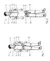
- the play figure 1 has a head part 2, which is connected via a neck joint 3 to a body portion 4 of a body 5 of the playing figure 1.
- the fuselage section 4 is connected via a latching / plug connection with latching elements 6 and plug-in elements 7 to a hip section 8 of the carcass 5.
- the locking elements 6 are integrally formed on the hip portion 8.
- the plug-in elements 7 are integrally formed on the body portion 4.
- arm joint balls 9 are formed on the body portion, which form with appropriate complementarily shaped joint pans shoulder joints of the character 1.
- the sockets are part of arms 10 of the character.
- Each of the arms 10 has an upper arm portion and a lower arm portion, which are each articulated to each other via an elbow joint 11.
- the arms 10 are multi-component injection molded parts, with the upper arm portions injection molded from a different plastic material than the lower arm portions.
- the elbow joints 11 are formed during injection molding. An assembly of the arms 10 is therefore not required.
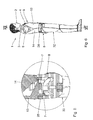
- a joint carrier 12 is formed (see. Fig. 9 ).
- Fig. 9 illustrates the component structure of the fuselage section 4. This has in addition to the head part 2 and the two joint supports 12 with the arm joint balls 9, a chest part 13 and a back part 14.
- the chest part 13 represents a breast-side torso subsection of the playing piece 1.
- the back part 14 represents a back-side torso subsection of the playing piece 1.
- To neck joint 3 includes a neck-neck neck joint body 15 which has a plurality of spherical surface portions 16, 17 and 18, which in the sectional view to Fig. 10 are visible.
- the surface portions 16 to 18 of the neck joint body 15 are clamped between a total of three joint counter walls 19, 20 and 21 of the body portion 4.
- the articulating mating wall 19 is an integral part of the chest part 13.
- the hinge mating walls 20, 21 are integral parts of the back part 14.
- the bias of the neck hinge body 15 between the hinge mating walls 19 to 21 is such that between the neck hinge body 15 and the joint counter walls 19 to 21, a frictional engagement is present, on the one hand ensures a mobility of the head part 2 relative to the body portion 4 and on the other hand ensures that the head part 2 remains in a predetermined relative position to the body portion 4.
- the Fig. 10 shows the neck joint 3 in a position "upright head” of the head part 2 relative to the body portion 4.
- the Fig. 13 shows the neck joint 3 in a pitching position of the head part 2 to the body portion 4.
- this pitching position acts a pitch stop 22, which is adjacent to the spherical surface portion 16 on the neck joint body 15, with a counter-stop 23 on the front side of the joint counter-wall 21st together.
- Another, rear pitch stop 24 is in the pitch position provided for cooperation with a counter-recess 25 in the hinge-back wall 20.
- the rear pitch stop 24 also has the function of a pivot counter-stop for limiting a maximum head-pivot angle of the game character 1 relative to the fuselage section 4th
- the two fuselage subsections 13, 14 are latched together on the neck side, as also for example from the Fig. 10 evident.
- a locking lug 26 of the chest part 13 engages behind a locking rib 27 of the back 14.
- the locking rib 27 is designed so elastic that they can initially dodge resiliently for insertion of the locking lug 26 when locking the chest part 13 with the back part 14 down.
- the two trunk subsections 13, 14 are inserted into the hip section 8, as in FIG Fig. 5 shown.
- a breast-side of the plug-in elements 7, which is integrally formed on the chest part 13, is inserted into the hip portion.
- a belt part 28 of the toy figure 1 is arranged on the visible side between the chest part 13 and the hip section 8.
- the further back-side plug element 7 is integrally formed on the back part 14 and inserted into the belt part 28.
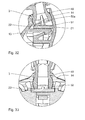
- Fig. 12 shows in a section the neck joint body 15 in a head pivot position "looking forward”.
- the Fig. 14 shows the neck joint body 15 in a head pivot position "look over the left shoulder".
- a pivot stop 30 which is an integral part of the chest part 13.
- Mirror symmetrical to the pivot stop 30 for the view over the left shoulder another pivot stop 31 is arranged to limit the head pivot angle when looking over the right shoulder.
- the pivot stop 31 is also an integral part of the chest part thirteenth
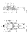
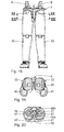
- the play figure 1 has two leg sections 32, 33, which are connected via leg-ball joints 34, 35 with the hip section 8 of the body 5.
- the leg sections 32, 33 each have a knee joint.
- the leg sections 32, 33 are multi-component injection molded parts which do not have to be mounted after injection molding but, in the illustrated multi-part design, are the direct result of the injection molding process.
- Each of the leg and ball joints 34, 35 has a leg joint ball 36, 37.
- the leg joint ball 36 is mounted in a socket 38 of the leg portion 32.
- the leg joint ball 37 is mounted in a socket 39 of the leg portion 33.
- the leg joint balls 36, 37 constitute joint elements of the leg and ball joints 34, 35.
- the joint sockets 38, 39 constitute counter-joint elements of the leg sections 32, 33.
- On the ball joint 36 there is integrally formed a leg retaining section 40 for the right Leg section 32 of the character 1 molded.
- To the leg joint ball 37 is integrally formed a leg-holding portion 41 for the leg portion for the left leg of the character 1.
- the two joint balls 36, 37 releasably connected to each other.
- the toy figure 1 is a "thigh joint", as far as the arrangement of the joint ball and socket, inversely formed than in real people. Instead of a thigh neck, the toy figure 1 has the joint pans 38, 39. Instead of a pelvic girdle, the toy figure 1 the two leg-joint balls 36, 37 connected to each other via the leg-holding portions 40, 41.
- leg-holding portion 41 is designed as a dovetail holding portion and that the leg-holding portion 40 is designed as a counter-holding portion complementary thereto.
- a dovetail profile 42 of the leg-holding portion 41 extends vertically when standing game piece 1.
- leg-holding sections 40, 41 and thus the leg sections 32, 33 are fixed on the hip section 8 via a latching device 43 and secured against slipping out.
- Locking projections 44 which are part of the latching device 43, are integrally formed on the leg-holding portions 40, 41.
- the locking projections 44 of the two leg-holding portions 40, 41 are arranged opposite to each other.
- a counter-latching body 45 of the latching device 43 which is integrally formed on the hip portion 8, is arranged between the two remaining projections 44.
- the two latching projections 44 engage behind latching steps 46 of the counter-latching body 45.
- leg-holding portions 40, 41 each have two pairs of opposing locking projections 44, each having intermediate portions 45 a. 45b of the counter-latching body 45 latching on the breast side and back together interact.
- the counter-latching body 45 has, in each case facing the leg-holding portion 40 on the one hand and the leg-holding portion 41 on the other hand, two separate dovetail profiles 47, for the secure connection of the hip portion 8 cooperate with the holding portions 40, 41 with complementary counter-guides of the leg-holding portions 40, 41 for the formation of two further dovetail connections.
- the dovetail joints made with the dovetail profiles 47 between the waist portion 8 and the leg support portions 40, 41 are located above the dovetail profile 42 directly above the dovetail profile 42 between the two leg support portions 40, 41 when the toy 1 is upright. This is from the supervision after Fig.
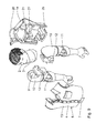
- Fig. 21 shows in a corresponding view of an assembly with the two leg portions 32, 33 and the patch waist portion 8 together with the belt part 28th
- the Fig. 24 to 27 illustrate a mounting sequence in the assembly of the assembly, which consists of the leg portions 32, 33, the waist portion 8 and the belt portion 28.
- the two leg sections 32, 33 connected to each other via the dovetail connection with the dovetail profile 42.
- the hip portion 8 is inserted from above into the dovetail connections with the dovetail profiles 47 and latched via the locking device 43 with the leg portions 32, 33.
- the belt part 28 is attached from above to the hip portion 8.
- FIGS. 28 to 36 Based on FIGS. 28 to 36 a further embodiment of a toy figure 48 is explained below. Components corresponding to those described above with reference to the character 1 after Fig. 1 to 27 have already been explained, have the same reference numbers and will not be discussed again in detail.
- a neck-neck-neck body 49 has a two-part, crowned abutment-pin area 50 in the play figure 48, which, like the Fig. 34 illustrates, two right and left of the neck joint body 49 opposite pin portions 50a, 50b has.
- the neck-joint body 49 abuts on a spherical surface portion 51 of the abutment-pin portion 50 on the hinge-back wall 21 of the back portion 14.
- the abutment pin areas 50a, 50b simultaneously have the function of a pivot counter stop for limiting a head pivot angle. This feature is in the Fig. 36 shown in the head position "look over the left shoulder" of the character 48.
- the two abutment pin areas 50a, 50b act as pivot counterstops with a stop rib 52 of the body portion 4 of the play figure 48.
Abstract
Description
Die Erfindung betrifft eine Spielfigur.The invention relates to a character.
Derartige Spielfiguren sind beispielsweise bekannt aus der
Es ist eine Aufgabe der vorliegenden Erfindung, Spielfiguren zu schaffen, die einerseits naturgetreue Bewegungsmöglichkeiten der Gliedmaßen ermöglichen, und die andererseits auch für kleinere Kinder möglichst spielsicher gestaltet sind.It is an object of the present invention to provide game characters that allow on the one hand lifelike movement possibilities of the limbs, and on the other hand are designed as safe as possible play for smaller children.
Diese Aufgabe ist erfindungsgemäß nach einem ersten Aspekt gelöst durch eine Spielfigur mit den im Anspruch 1 angegebenen Merkmalen und nach einem zweiten Aspekt durch eine Spielfigur mit den im Anspruch 6 angegebenen Merkmalen.This object is achieved according to a first aspect of a game character with the features specified in
Erfindungsgemäß wurde erkannt, dass eine Gelenkelement-Verbindung über Bein-Halteabschnitte einerseits zur Möglichkeit führt, die Bein-Abschnitte separat zu fertigen und anschließend zu montieren, andererseits aber auch eine Stabilität der Spielfigur bei guter Beweglichkeit gewährleistet.According to the invention, it has been recognized that a joint element connection via leg holding sections on the one hand leads to the possibility to manufacture the leg sections separately and then to assemble, but on the other hand also ensures stability of the play figure with good mobility.
Eine formschlüssige Verbindung der Bein-Halteabschnitte nach Anspruch 2 gewährleistet eine sichere Verbindung der beiden Bein-Halteabschnitte miteinander. Die formschlüssige Verbindung kann durch Ausführung eines der beiden Bein-Halteabschnitte als Schwalbenschwanz-Halteabschnitt und des anderen der beiden Bein-Halteabschnitte als hierzu komplementären Gegen-Halteabschnitt ausgeführt sein. Eine solche SchwalbenschwanzVerbindung gewährleistet eine stabile Verbindung der beiden Bein-Halteabschnitte miteinander. Auch eine andere formschlüssige Verbindung der Bein-Halteabschnitte miteinander ist möglich, beispielsweise eine Verbindung nach Art eines Druckknopfes.A positive connection of the leg-holding sections according to
Eine Rasteinrichtung nach Anspruch 3 gewährleistet bei einfacher Montage eine sichere Fixierung der miteinander verbundenen Bein-Abschnitte am Hüftabschnitt.A latching device according to
Angeformte Rastvorsprünge nach Anspruch 4 lassen sich kostengünstig herstellen.Shaped locking projections according to
Einander nach Anspruch 5 gegenüberliegend angeordnete Rastvorsprünge ermöglichen eine zwangsgesicherte Ausgestaltung der Rasteinrichtung, die die Bein-Abschnitte am Hüftabschnitt fixiert. Es ist eine Gestaltung möglich, bei der, sobald durch eine Bein-Gelenkbewegung einer der Rastvorsprünge vom Gegen-Rastkörper abhebt, der Gegen-Rastkörper gegen den anderen, gegenüberliegenden Rastvorsprung gepresst wird. Die Rasteinrichtung, die die Bein-Abschnitte am Hüftabschnitt fixiert, kann mehrere einander gegenüberliegende Paare von Rastvorsprüngen aufweisen. Diese mehreren Rastvorsprung-Paare können einstückig an den Bein-Halteabschnitten angeformt sein.Mutually arranged according to claim 5 locking projections allow a positively secured configuration of the latching device which fixes the leg sections on the hip portion. A design is possible in which, as soon as one of the latching projections lifts off from the counter-latching body by a leg-joint movement, the counter-latching element is pressed against the other, opposite latching projection. The latching device which fixes the leg portions to the hip portion may have a plurality of mutually opposite pairs of latching projections. These plurality of locking projection pairs may be integrally formed on the leg holding portions.
Erfindungsgemäß wurde weiterhin erkannt, dass ein Kopfteil mit einem zwischen Gelenk-Gegenwänden des Rumpfabschnitts eingespannten, halsseitigen Gelenkkörper eine einfache Möglichkeit schafft, eine jeweils vorgegebene Relativstellung des Kopfteils zum Rumpfabschnitt über einen Reibschluss zu fixieren. Der Reibschluss wird durch eine Vorspannung der Gelenk-Gegenwände gegeneinander erzeugt.According to the invention, it has furthermore been recognized that a head part with a neck-side joint body clamped between joint counter walls of the body section provides a simple possibility of fixing a respectively predetermined relative position of the head part to the body section via a frictional connection. The frictional engagement is generated by a bias of the joint counter walls against each other.
Mindestens ein balliger Flächenabschnitt nach Anspruch 7 gewährleistet eine definierte Anlage des Hals-Gelenkkörpers an den Gelenk-Gegenwänden.At least one spherical surface portion according to
Entsprechendes gilt für einen Anlage-Stiftbereich nach Anspruch 8.The same applies to a contactor pin area according to
Bei einer mehrteiligen Gestaltung des Rumpfabschnittes nach Anspruch 9 kann eine zusätzliche Vorspannung des Halsgelenks über eine Vorspannung zwischen den beiden Rumpfabschnitten erzeugt werden.In a multi-part design of the fuselage section according to
Ein Nick-Anschlag nach Anspruch 10 und Schwenk-Anschläge nach Anspruch 11 gewährleisten realistische Begrenzungen der Kopfbewegungen der Spielfigur.A pitch stop according to
Eine Rastverbindung der beiden Rumpf-Unterabschnitte nach Anspruch 12 ermöglicht eine sichere Verbindung dieser beiden Rumpfabschnitte. Zudem ist eine definierte Vorgabe einer Vorspannung der Gelenk-Gegenwände des Halsgelenks möglich.A latching connection of the two fuselage subsections according to
Eine Steckverbindung der Rumpf-Unterabschnitte mit dem Hüftabschnitt nach Anspruch 13 ist einfach.A connector of the trunk subsections to the hip portion according to
Eine Ausgestaltung von Figurenteilen als Mehrkomponenten-Spritzgussteile nach Anspruch 14 ergibt neue Freiheitsgrade bei der Gestaltung der Spielfigur. Es können Figurenteile mit Gelenken versehen werden, die gleich während des Spritzgussprozesses hergestellt werden können, also nicht nachträglich montiert werden müssen. Beispiele für derartige Spielfiguren-Gelenke sind Ellbogengelenke und Kniegelenke. Auch farbliche Absetzungen sind durch den Mehrkomponentenspritzguss möglich. Zudem ist es möglich, stark beanspruchte Komponenten, beispielsweise Gelenkkomponenten, aus entsprechend verschleißfesten Kunststoffmaterialien zu fertigen, wohingegen andere Komponenten des gleichen Figurenteils aus weniger verschleißfestem Material gefertigt sein können.An embodiment of figure parts as multi-component injection molded parts according to
Ausführungsbeispiele der Erfindung werden nachfolgend anhand der Zeichnung näher erläutert. In dieser zeigen:
- Fig. 1
- eine perspektivische Ansicht einer Spielfigur;
- Fig. 2
- die Spielfigur nach
Fig. 1 in einer Explosionsdarstellung, bei der ein Rumpfabschnitt eines Korpus von einem Hüftabschnitt des Korpus getrennt ist; - Fig. 3
- eine Vorderansicht der Spielfigur nach
Fig. 1 ; - Fig. 4
- einen Schnitt gemäß Linie IV-IV in
Fig. 3 ; - Fig. 5
- eine Ausschnittsvergrößerung des Details V in
Fig. 4 ; - Fig. 6
- eine Seitenansicht der Spielfigur mit abgenommenen Armen;
- Fig. 7
- einen Schnitt gemäß Linie VII-VII in
Fig. 6 ; - Fig. 8
- vergrößert das Detail VIII in
Fig. 7 ; - Fig. 9
- eine Explosionsdarstellung des Rumpfabschnitts sowie des Kopfes und der Arme der Spielfigur nach
Fig. 1 ; - Fig. 10
- vergrößert das Detail X in
Fig. 4 ; - Fig. 11
- einen Schnitt gemäß Linie XI-XI in
Fig. 3 ; - Fig. 12
- vergrößert das Detail XII in
Fig. 11 ; - Fig. 13
- in einer zur
Fig. 10 ähnlichen Darstellung eine Nickstellung des Kopfes relativ zum Rumpfabschnitt; - Fig. 14
- in einer zur
Fig. 12 ähnlichen Darstellung eine Schwenkstellung des Kopfes relativ zum Rumpfabschnitt "Blick über die linke Schulter"; - Fig. 15
- die beiden Beinabschnitte der Spielfigur nach
Fig. 1 in einer zusammengesteckten Stellung; - Fig. 16
- eine Draufsicht auf die Beinabschnitte in der Stellung nach
Fig. 15 ; - Fig. 17
- einen Schnitt gemäß Linie XVII-XVII in
Fig. 15 ; - Fig. 18
- eine Vorderansicht der Beinabschnitte, eingesteckt in den Hüftabschnitt des Korpus;
- Fig. 19
- einen Schnitt gemäß Linie XIX-XIX in
Fig. 18 ; - Fig. 20
- einen Schnitt gemäß Linie XX-XX in
Fig. 18 ; - Fig. 21
- eine Aufsicht auf die Spielfigur-Baugruppe nach
Fig. 18 ; - Fig. 22
- einen Schnitt gemäß Linie XXII-XXII in
Fig. 21 ; - Fig. 23
- einen Schnitt gemäß Linie XXIII-XXIII in
Fig. 21 ; - Fig. 24-27
- Explosionsdarstellungen, die eine Montageabfolge der Baugruppe nach
Fig. 18 inklusive eines Spielfiguren-Gürtels zeigen; - Fig. 28
- perspektivisch eine weitere Ausführung einer Spielfigur;
- Fig. 29
- eine Vorderansicht eines Rumpfabschnitts der Spielfigur nach
Fig. 28 ; - Fig. 30
- einen Schnitt gemäß Linie XXX-XXX in
Fig. 29 ; - Fig. 31
- vergrößert das Detail XXXI in
Fig. 30 ; - Fig. 32
- in einer zur
Fig. 28 ähnlichen Darstellung eine Nickstellung des Kopfes relativ zum Rumpfabschnitt; - Fig. 33
- eine Ausschnittsvergrößerung eines Schnitts gemäß Linie XXXIII-XXXIII im Bereich eines Kopf-/Rumpfübergangs;
- Fig. 34
- perspektivisch das Kopfteil der Spielfigur nach
Fig. 28 ; - Fig. 35
- den Rumpf der Spielfigur nach
Fig. 28 in einer Vorderansicht mit dem Kopf in der Stellung "Blick über die linke Schulter"; und - Fig. 36
- vergrößert einen Ausschnitt gemäß Linie XXXVI-XXXVI in
Fig. 35 .
- Fig. 1
- a perspective view of a toy figure;
- Fig. 2
- the character after
Fig. 1 in an exploded view, in which a body portion of a body is separated from a waist portion of the body; - Fig. 3
- a front view of the character after
Fig. 1 ; - Fig. 4
- a section along line IV-IV in
Fig. 3 ; - Fig. 5
- a detail enlargement of the detail V in
Fig. 4 ; - Fig. 6
- a side view of the character with arms removed;
- Fig. 7
- a section according to line VII-VII in
Fig. 6 ; - Fig. 8
- enlarged detail VIII in
Fig. 7 ; - Fig. 9
- an exploded view of the torso section and the head and arms of the character after
Fig. 1 ; - Fig. 10
- enlarges the detail X in
Fig. 4 ; - Fig. 11
- a section along line XI-XI in
Fig. 3 ; - Fig. 12
- enlarges detail XII in
Fig. 11 ; - Fig. 13
- in a to
Fig. 10 similar representation of a pitching of the head relative to the body portion; - Fig. 14
- in a to
Fig. 12 similar representation of a pivoting position of the head relative to the body portion "view of the left shoulder"; - Fig. 15
- the two leg sections of the character after
Fig. 1 in a mated position; - Fig. 16
- a plan view of the leg portions in the position after
Fig. 15 ; - Fig. 17
- a section according to line XVII-XVII in
Fig. 15 ; - Fig. 18
- a front view of the leg portions, inserted in the waist portion of the body;
- Fig. 19
- a section along line XIX-XIX in
Fig. 18 ; - Fig. 20
- a section along line XX-XX in
Fig. 18 ; - Fig. 21
- a view of the game character assembly after
Fig. 18 ; - Fig. 22
- a section according to line XXII-XXII in
Fig. 21 ; - Fig. 23
- a section along line XXIII-XXIII in
Fig. 21 ; - Fig. 24-27
- Exploded views, the assembly sequence of the assembly after
Fig. 18 including a figurine belt; - Fig. 28
- in perspective, another embodiment of a character;
- Fig. 29
- a front view of a fuselage section of the character after
Fig. 28 ; - Fig. 30
- a section along line XXX-XXX in
Fig. 29 ; - Fig. 31
- enlarges the detail XXXI in
Fig. 30 ; - Fig. 32
- in a to
Fig. 28 similar representation of a pitching of the head relative to the body portion; - Fig. 33
- an enlarged detail of a section according to line XXXIII-XXXIII in the region of a head / trunk transition;
- Fig. 34
- in perspective, the headboard of the character after
Fig. 28 ; - Fig. 35
- the hull of the character after
Fig. 28 in a front view with the head in the position "view over the left shoulder"; and - Fig. 36
- enlarges a section according to line XXXVI-XXXVI in
Fig. 35 ,
Im Schulterbereich sind an den Rumpfabschnitt 4 Arm-Gelenkkugeln 9 angeformt, die mit entsprechend komplementär ausgeformten Gelenkpfannen Schultergelenke der Spielfigur 1 bilden. Die Gelenkpfannen sind Teil von Armen 10 der Spielfigur. Jeder der Arme 10 hat einen Oberarmabschnitt und einen Unterarmabschnitt, die jeweils über ein Ellbogengelenk 11 gelenkig miteinander verbunden sind. Die Arme 10 sind Mehrkomponenten-Spritzgussteile, wobei die Oberarmabschnitte aus einem anderen Kunststoffmaterial spritzgegossen sind als die Unterarmabschnitte. Die Ellbogengelenke 11 werden beim Spritzgießen ausgebildet. Eine Montage der Arme 10 ist daher nicht erforderlich.In the
An jeder der Arm-Gelenkkugeln 9 ist ein Gelenkträger 12 angeformt (vgl.
Zum Halsgelenk 3 gehört ein halsseitiger Hals-Gelenkkörper 15, der mehrere ballige Flächenabschnitte 16, 17 und 18 aufweist, die in der Schnittdarstellung nach
Die
Die beiden Rumpf-Unterabschnitte 13, 14 sind halsseitig miteinander verrastet, wie ebenfalls beispielsweise aus der
Hüftseitig sind die beiden Rumpf-Unterabschnitte 13, 14 in den Hüftabschnitt 8 eingesteckt, wie in der
Zur Fixierung des in den Hüftabschnitt 8 eingesteckten Rumpfabschnitt 4 dienen die Rastelemente 6, die mit Gegen-Rastelementen 29, die einstückig am Rückenteil 14 angeformt sind, verrastet sind.To fix the inserted into the
Die Spielfigur 1 hat zwei Bein-Abschnitte 32, 33, die über Bein-Kugelgelenke 34, 35 mit dem Hüftabschnitt 8 des Korpus 5 verbunden sind. Die Bein-Abschnitte 32, 33 haben jeweils ein Kniegelenk. Die Bein-Abschnitte 32, 33 sind Mehrkomponenten-Spritzgussteile, die nach der Spritzgussfertigung nicht montiert werden müssen, sondern in der dargestellten Mehrteiligkeit das direkte Ergebnis des Spritzgussprozesses sind.The play figure 1 has two
Jedes der Bein-Kugelgelenke 34, 35 hat eine Bein-Gelenkkugel 36, 37. Die Bein-Gelenkkugel 36 ist in einer Gelenkpfanne 38 des Bein-Abschnitts 32 gelagert. Die Bein-Gelenkkugel 37 ist in einer Gelenkpfanne 39 des Bein-Abschnitts 33 gelagert. Die Bein-Gelenkkugeln 36, 37 stellen Gelenkelemente der Bein-Kugelgelenke 34, 35 dar. Die Gelenkpfannen 38, 39 stellen Gegen-Gelenkelemente der Bein-Abschnitte 32, 33 dar. An der Gelenkkugel 36 ist einstückig ein Bein-Halteabschnitt 40 für den rechten Bein-Abschnitt 32 der Spielfigur 1 angeformt. An die Bein-Gelenkkugel 37 ist einstückig ein Bein-Halteabschnitt 41 für den Bein-Abschnitt für das linke Bein der Spielfigur 1 angeformt. Über die beiden Bein-Halteabschnitte 40, 41 sind die beiden Gelenkkugeln 36, 37 lösbar miteinander verbunden. Bei der Spielfigur 1 ist ein "Oberschenkelgelenk", was die Anordnung von Gelenkkugel und Gelenkpfanne angeht, umgekehrt ausgebildet als beim realen Menschen. Anstelle eines Oberschenkelhalses hat die Spielfigur 1 die Gelenkpfannen 38, 39. Anstelle eines Beckengürtels hat die Spielfigur 1 die beiden miteinander über die Bein-Halteabschnitte 40, 41 verbundenen Bein-Gelenkkugeln 36, 37.Each of the leg and
Aus den
Die Bein-Halteabschnitte 40, 41 und damit die Bein-Abschnitte 32, 33 sind über eine Rasteinrichtung 43 am Hüftabschnitt 8 fixiert und gegen ein Herausrutschen gesichert.The leg-holding
Rastvorsprünge 44, die Teil der Rasteinrichtung 43 sind, sind an den Bein-Halteabschnitten 40, 41 einstückig angeformt. Die Rastvorsprünge 44 der beiden Bein-Halteabschnitte 40, 41 sind einander gegenüberliegend angeordnet. Ein Gegen-Rastkörper 45 der Rasteinrichtung 43, der einstückig am Hüftabschnitt 8 angeformt ist, ist zwischen den beiden Restvorsprüngen 44 angeordnet. Die beiden Rastvorsprünge 44 hintergreifen Gegen-Raststufen 46 des Gegen-Rastkörpers 45.Locking
Wie aus der
Der Gegen-Rastkörper 45 hat, jeweils dem Bein-Halteabschnitt 40 einerseits und dem Bein-Halteabschnitt 41 andererseits zugewandt, zwei eigene Schwalbenschwanzprofile 47, die zur sicheren Verbindung des Hüftabschnitts 8 mit den Halteabschnitten 40, 41 mit komplementären Gegenführungen der Bein-Halteabschnitte 40, 41 zur Ausbildung zweier weiterer Schwalbenschwanzverbindungen zusammenwirken. Die Schwalbenschwanzverbindungen, die mit den Schwalbenschwanzprofilen 47 zwischen dem Hüftabschnitt 8 und den Bein-Halteabschnitten 40, 41 hergestellt werden, sind bei stehender Spielfigur 1 oberhalb der Schwalbenschwanzverbindung über das Schwalbenschwanzprofil 42 direkt zwischen den beiden Bein-Halteabschnitten 40, 41 angeordnet. Dies wird aus der Aufsicht nach
Über die Paare der Rastvorsprünge 44 und den dazwischen liegenden Gegen-Rastkörper 45 ergibt sich eine Zwangssicherung bei der Bewegung der Oberschenkelteile der Bein-Abschnitte 32, 33 relativ zum Korpus 5 über die Bein-Kugelgelenke 34. 35. Sobald durch eine Gelenkbewegung der Bein-Kugelgelenke 34, 35 einer der Rastvorsprünge 44 vom Gegen-Rastkörper 45 abhebt, wird der Gegen-Rastkörper 45 hierdurch zwangsweise gegen den gegenüberliegenden, anderen Rastvorsprung 44 gepresst. Auf diese Weise ist sichergestellt, dass die beiden Bein-Abschnitte 32, 33 am Hüftabschnitt 8 fixiert bleiben.About the pairs of locking
Die
Anhand der
Ein halsseitiger Hals-Gelenkkörper 49 hat bei der Spielfigur 48 einen zweigeteilten, balligen Anlage-Stiftbereich 50, der, wie die
Claims (14)
Priority Applications (1)
| Application Number | Priority Date | Filing Date | Title |
|---|---|---|---|
| PL12152204T PL2484417T3 (en) | 2011-02-02 | 2012-01-24 | Toy figure |
Applications Claiming Priority (1)
| Application Number | Priority Date | Filing Date | Title |
|---|---|---|---|
| DE202011002298U DE202011002298U1 (en) | 2011-02-02 | 2011-02-02 | game piece |
Publications (3)
| Publication Number | Publication Date |
|---|---|
| EP2484417A2 true EP2484417A2 (en) | 2012-08-08 |
| EP2484417A3 EP2484417A3 (en) | 2012-10-03 |
| EP2484417B1 EP2484417B1 (en) | 2015-07-15 |
Family
ID=45509322
Family Applications (1)
| Application Number | Title | Priority Date | Filing Date |
|---|---|---|---|
| EP12152204.9A Active EP2484417B1 (en) | 2011-02-02 | 2012-01-24 | Toy figure |
Country Status (6)
| Country | Link |
|---|---|
| EP (1) | EP2484417B1 (en) |
| DE (1) | DE202011002298U1 (en) |
| DK (1) | DK2484417T3 (en) |
| ES (1) | ES2544927T3 (en) |
| HU (1) | HUE025254T2 (en) |
| PL (1) | PL2484417T3 (en) |
Citations (2)
| Publication number | Priority date | Publication date | Assignee | Title |
|---|---|---|---|---|
| WO2002011844A1 (en) | 2000-08-04 | 2002-02-14 | Mattel, Inc. | Appendage attachment mechanism for toy figures |
| US20020127949A1 (en) | 1998-06-01 | 2002-09-12 | Lee James S.W. | Toy figure with articulating joints |
Family Cites Families (6)
| Publication number | Priority date | Publication date | Assignee | Title |
|---|---|---|---|---|
| US1270781A (en) * | 1917-11-10 | 1918-07-02 | Charles Cabana | Ball-and-socket joint for toys. |
| GB1604806A (en) * | 1977-11-21 | 1981-12-16 | Cpg Prod Corp | Toy figures |
| US4995846A (en) * | 1990-02-02 | 1991-02-26 | The Little Tikes Company | Toy figure with pivotal lower torso |
| JP3341213B2 (en) * | 2000-10-13 | 2002-11-05 | 株式会社ボークス | Doll toy |
| US7077717B2 (en) * | 2003-05-27 | 2006-07-18 | Mattel, Inc. | Doll with angled and jointed torso |
| CN201439027U (en) * | 2009-05-08 | 2010-04-21 | 陈邱和美 | Movable part connecting structure |
-
2011
- 2011-02-02 DE DE202011002298U patent/DE202011002298U1/en not_active Expired - Lifetime
-
2012
- 2012-01-24 PL PL12152204T patent/PL2484417T3/en unknown
- 2012-01-24 HU HUE12152204A patent/HUE025254T2/en unknown
- 2012-01-24 EP EP12152204.9A patent/EP2484417B1/en active Active
- 2012-01-24 DK DK12152204.9T patent/DK2484417T3/en active
- 2012-01-24 ES ES12152204.9T patent/ES2544927T3/en active Active
Patent Citations (2)
| Publication number | Priority date | Publication date | Assignee | Title |
|---|---|---|---|---|
| US20020127949A1 (en) | 1998-06-01 | 2002-09-12 | Lee James S.W. | Toy figure with articulating joints |
| WO2002011844A1 (en) | 2000-08-04 | 2002-02-14 | Mattel, Inc. | Appendage attachment mechanism for toy figures |
Also Published As
| Publication number | Publication date |
|---|---|
| HUE025254T2 (en) | 2016-02-29 |
| DK2484417T3 (en) | 2015-10-26 |
| EP2484417A3 (en) | 2012-10-03 |
| ES2544927T3 (en) | 2015-09-07 |
| PL2484417T3 (en) | 2015-12-31 |
| EP2484417B1 (en) | 2015-07-15 |
| DE202011002298U1 (en) | 2012-05-16 |
Similar Documents
| Publication | Publication Date | Title |
|---|---|---|
| DE2850292A1 (en) | JOINT CONSTRUCTION FOR A MANNEQUIN | |
| WO2012101171A1 (en) | Panel | |
| DE1478546A1 (en) | Doll limbs, their attachment to a doll and their manufacturing process | |
| DE2506786C3 (en) | Composable toy figure | |
| DE2041468A1 (en) | Doll with hinged limbs | |
| EP0174531A2 (en) | Joint endoprosthesis | |
| DE2605438A1 (en) | ZIPPER WITH DIVISIBLE END COUPLING | |
| DE102016007403B4 (en) | Joint as a connecting part between a spectacle front glasses and their ironing | |
| DE2700969C3 (en) | Pair of legs in a composite toy figure | |
| DE102019110723A1 (en) | Decorative toy for fusible toy beads and set of fusible toy beads | |
| DE2707210A1 (en) | TOY FIGURE | |
| CH617584A5 (en) | ||
| EP2484417B1 (en) | Toy figure | |
| DE1138428B (en) | Spectacle temple arrangement with an electrical system, in particular a hearing device | |
| DE2207796A1 (en) | puppet | |
| DE3545127A1 (en) | MOVING TOY FIGURE | |
| WO2005056143A1 (en) | Doll joint | |
| DE60029226T2 (en) | DOLL WITH REALISTIC ROTATABLE WAIST | |
| DE19710934A1 (en) | Artificial rod end for the human hip joint | |
| DE8618965U1 (en) | Mother doll | |
| EP0100959B1 (en) | Articulated figure | |
| DE2625851A1 (en) | GAME PIECE | |
| DE3800290C2 (en) | ||
| DE4040737A1 (en) | Adjustable skeleton for textile puppets - has separate arms and legs of punched plate which attach securely to punched trunk by hooked ends and plastic head holder fixed to neck | |
| DE4026059C2 (en) |
Legal Events
| Date | Code | Title | Description |
|---|---|---|---|
| PUAI | Public reference made under article 153(3) epc to a published international application that has entered the european phase |
Free format text: ORIGINAL CODE: 0009012 |
|
| AK | Designated contracting states |
Kind code of ref document: A2 Designated state(s): AL AT BE BG CH CY CZ DE DK EE ES FI FR GB GR HR HU IE IS IT LI LT LU LV MC MK MT NL NO PL PT RO RS SE SI SK SM TR |
|
| AX | Request for extension of the european patent |
Extension state: BA ME |
|
| PUAL | Search report despatched |
Free format text: ORIGINAL CODE: 0009013 |
|
| AK | Designated contracting states |
Kind code of ref document: A3 Designated state(s): AL AT BE BG CH CY CZ DE DK EE ES FI FR GB GR HR HU IE IS IT LI LT LU LV MC MK MT NL NO PL PT RO RS SE SI SK SM TR |
|
| AX | Request for extension of the european patent |
Extension state: BA ME |
|
| RIC1 | Information provided on ipc code assigned before grant |
Ipc: A63H 3/46 20060101AFI20120827BHEP |
|
| 17P | Request for examination filed |
Effective date: 20121210 |
|
| GRAP | Despatch of communication of intention to grant a patent |
Free format text: ORIGINAL CODE: EPIDOSNIGR1 |
|
| INTG | Intention to grant announced |
Effective date: 20150212 |
|
| GRAS | Grant fee paid |
Free format text: ORIGINAL CODE: EPIDOSNIGR3 |
|
| GRAA | (expected) grant |
Free format text: ORIGINAL CODE: 0009210 |
|
| AK | Designated contracting states |
Kind code of ref document: B1 Designated state(s): AL AT BE BG CH CY CZ DE DK EE ES FI FR GB GR HR HU IE IS IT LI LT LU LV MC MK MT NL NO PL PT RO RS SE SI SK SM TR |
|
| REG | Reference to a national code |
Ref country code: CH Ref legal event code: EP Ref country code: GB Ref legal event code: FG4D Free format text: NOT ENGLISH |
|
| REG | Reference to a national code |
Ref country code: SE Ref legal event code: TRGR |
|
| REG | Reference to a national code |
Ref country code: NL Ref legal event code: T3 Ref country code: IE Ref legal event code: FG4D Free format text: LANGUAGE OF EP DOCUMENT: GERMAN |
|
| REG | Reference to a national code |
Ref country code: AT Ref legal event code: REF Ref document number: 736478 Country of ref document: AT Kind code of ref document: T Effective date: 20150815 |
|
| REG | Reference to a national code |
Ref country code: DE Ref legal event code: R096 Ref document number: 502012003778 Country of ref document: DE |
|
| REG | Reference to a national code |
Ref country code: ES Ref legal event code: FG2A Ref document number: 2544927 Country of ref document: ES Kind code of ref document: T3 Effective date: 20150907 |
|
| REG | Reference to a national code |
Ref country code: DK Ref legal event code: T3 Effective date: 20151020 |
|
| REG | Reference to a national code |
Ref country code: RO Ref legal event code: EPE |
|
| REG | Reference to a national code |
Ref country code: LT Ref legal event code: MG4D |
|
| REG | Reference to a national code |
Ref country code: PL Ref legal event code: T3 |
|
| REG | Reference to a national code |
Ref country code: FR Ref legal event code: PLFP Year of fee payment: 5 |
|
| PG25 | Lapsed in a contracting state [announced via postgrant information from national office to epo] |
Ref country code: NO Free format text: LAPSE BECAUSE OF FAILURE TO SUBMIT A TRANSLATION OF THE DESCRIPTION OR TO PAY THE FEE WITHIN THE PRESCRIBED TIME-LIMIT Effective date: 20151015 Ref country code: GR Free format text: LAPSE BECAUSE OF FAILURE TO SUBMIT A TRANSLATION OF THE DESCRIPTION OR TO PAY THE FEE WITHIN THE PRESCRIBED TIME-LIMIT Effective date: 20151016 Ref country code: LV Free format text: LAPSE BECAUSE OF FAILURE TO SUBMIT A TRANSLATION OF THE DESCRIPTION OR TO PAY THE FEE WITHIN THE PRESCRIBED TIME-LIMIT Effective date: 20150715 Ref country code: LT Free format text: LAPSE BECAUSE OF FAILURE TO SUBMIT A TRANSLATION OF THE DESCRIPTION OR TO PAY THE FEE WITHIN THE PRESCRIBED TIME-LIMIT Effective date: 20150715 |
|
| PG25 | Lapsed in a contracting state [announced via postgrant information from national office to epo] |
Ref country code: RS Free format text: LAPSE BECAUSE OF FAILURE TO SUBMIT A TRANSLATION OF THE DESCRIPTION OR TO PAY THE FEE WITHIN THE PRESCRIBED TIME-LIMIT Effective date: 20150715 Ref country code: PT Free format text: LAPSE BECAUSE OF FAILURE TO SUBMIT A TRANSLATION OF THE DESCRIPTION OR TO PAY THE FEE WITHIN THE PRESCRIBED TIME-LIMIT Effective date: 20151116 Ref country code: HR Free format text: LAPSE BECAUSE OF FAILURE TO SUBMIT A TRANSLATION OF THE DESCRIPTION OR TO PAY THE FEE WITHIN THE PRESCRIBED TIME-LIMIT Effective date: 20150715 |
|
| REG | Reference to a national code |
Ref country code: HU Ref legal event code: AG4A Ref document number: E025254 Country of ref document: HU |
|
| REG | Reference to a national code |
Ref country code: DE Ref legal event code: R097 Ref document number: 502012003778 Country of ref document: DE |
|
| PG25 | Lapsed in a contracting state [announced via postgrant information from national office to epo] |
Ref country code: EE Free format text: LAPSE BECAUSE OF FAILURE TO SUBMIT A TRANSLATION OF THE DESCRIPTION OR TO PAY THE FEE WITHIN THE PRESCRIBED TIME-LIMIT Effective date: 20150715 Ref country code: SK Free format text: LAPSE BECAUSE OF FAILURE TO SUBMIT A TRANSLATION OF THE DESCRIPTION OR TO PAY THE FEE WITHIN THE PRESCRIBED TIME-LIMIT Effective date: 20150715 |
|
| PLBE | No opposition filed within time limit |
Free format text: ORIGINAL CODE: 0009261 |
|
| STAA | Information on the status of an ep patent application or granted ep patent |
Free format text: STATUS: NO OPPOSITION FILED WITHIN TIME LIMIT |
|
| 26N | No opposition filed |
Effective date: 20160418 |
|
| PG25 | Lapsed in a contracting state [announced via postgrant information from national office to epo] |
Ref country code: IS Free format text: LAPSE BECAUSE OF FAILURE TO SUBMIT A TRANSLATION OF THE DESCRIPTION OR TO PAY THE FEE WITHIN THE PRESCRIBED TIME-LIMIT Effective date: 20150715 |
|
| PG25 | Lapsed in a contracting state [announced via postgrant information from national office to epo] |
Ref country code: SI Free format text: LAPSE BECAUSE OF FAILURE TO SUBMIT A TRANSLATION OF THE DESCRIPTION OR TO PAY THE FEE WITHIN THE PRESCRIBED TIME-LIMIT Effective date: 20150715 Ref country code: LU Free format text: LAPSE BECAUSE OF FAILURE TO SUBMIT A TRANSLATION OF THE DESCRIPTION OR TO PAY THE FEE WITHIN THE PRESCRIBED TIME-LIMIT Effective date: 20160124 |
|
| PG25 | Lapsed in a contracting state [announced via postgrant information from national office to epo] |
Ref country code: MC Free format text: LAPSE BECAUSE OF FAILURE TO SUBMIT A TRANSLATION OF THE DESCRIPTION OR TO PAY THE FEE WITHIN THE PRESCRIBED TIME-LIMIT Effective date: 20150715 |
|
| REG | Reference to a national code |
Ref country code: IE Ref legal event code: MM4A |
|
| REG | Reference to a national code |
Ref country code: FR Ref legal event code: PLFP Year of fee payment: 6 |
|
| PG25 | Lapsed in a contracting state [announced via postgrant information from national office to epo] |
Ref country code: IE Free format text: LAPSE BECAUSE OF NON-PAYMENT OF DUE FEES Effective date: 20160124 |
|
| PG25 | Lapsed in a contracting state [announced via postgrant information from national office to epo] |
Ref country code: MT Free format text: LAPSE BECAUSE OF FAILURE TO SUBMIT A TRANSLATION OF THE DESCRIPTION OR TO PAY THE FEE WITHIN THE PRESCRIBED TIME-LIMIT Effective date: 20150715 |
|
| REG | Reference to a national code |
Ref country code: FR Ref legal event code: PLFP Year of fee payment: 7 |
|
| PG25 | Lapsed in a contracting state [announced via postgrant information from national office to epo] |
Ref country code: SM Free format text: LAPSE BECAUSE OF FAILURE TO SUBMIT A TRANSLATION OF THE DESCRIPTION OR TO PAY THE FEE WITHIN THE PRESCRIBED TIME-LIMIT Effective date: 20150715 Ref country code: CY Free format text: LAPSE BECAUSE OF FAILURE TO SUBMIT A TRANSLATION OF THE DESCRIPTION OR TO PAY THE FEE WITHIN THE PRESCRIBED TIME-LIMIT Effective date: 20150715 |
|
| PG25 | Lapsed in a contracting state [announced via postgrant information from national office to epo] |
Ref country code: MK Free format text: LAPSE BECAUSE OF FAILURE TO SUBMIT A TRANSLATION OF THE DESCRIPTION OR TO PAY THE FEE WITHIN THE PRESCRIBED TIME-LIMIT Effective date: 20150715 |
|
| PG25 | Lapsed in a contracting state [announced via postgrant information from national office to epo] |
Ref country code: BG Free format text: LAPSE BECAUSE OF FAILURE TO SUBMIT A TRANSLATION OF THE DESCRIPTION OR TO PAY THE FEE WITHIN THE PRESCRIBED TIME-LIMIT Effective date: 20150715 |
|
| PG25 | Lapsed in a contracting state [announced via postgrant information from national office to epo] |
Ref country code: AL Free format text: LAPSE BECAUSE OF FAILURE TO SUBMIT A TRANSLATION OF THE DESCRIPTION OR TO PAY THE FEE WITHIN THE PRESCRIBED TIME-LIMIT Effective date: 20150715 |
|
| PGFP | Annual fee paid to national office [announced via postgrant information from national office to epo] |
Ref country code: PL Payment date: 20221222 Year of fee payment: 12 |
|
| PGFP | Annual fee paid to national office [announced via postgrant information from national office to epo] |
Ref country code: RO Payment date: 20230113 Year of fee payment: 12 Ref country code: FR Payment date: 20230123 Year of fee payment: 12 Ref country code: FI Payment date: 20230119 Year of fee payment: 12 Ref country code: ES Payment date: 20230216 Year of fee payment: 12 Ref country code: DK Payment date: 20230123 Year of fee payment: 12 Ref country code: CZ Payment date: 20230112 Year of fee payment: 12 Ref country code: CH Payment date: 20230201 Year of fee payment: 12 Ref country code: AT Payment date: 20221223 Year of fee payment: 12 |
|
| PGFP | Annual fee paid to national office [announced via postgrant information from national office to epo] |
Ref country code: TR Payment date: 20230120 Year of fee payment: 12 Ref country code: SE Payment date: 20230123 Year of fee payment: 12 Ref country code: IT Payment date: 20230131 Year of fee payment: 12 Ref country code: HU Payment date: 20230123 Year of fee payment: 12 Ref country code: GB Payment date: 20230124 Year of fee payment: 12 Ref country code: DE Payment date: 20230329 Year of fee payment: 12 Ref country code: BE Payment date: 20230123 Year of fee payment: 12 |
|
| P01 | Opt-out of the competence of the unified patent court (upc) registered |
Effective date: 20230519 |
|
| PGFP | Annual fee paid to national office [announced via postgrant information from national office to epo] |
Ref country code: NL Payment date: 20230124 Year of fee payment: 12 |
|
| PGFP | Annual fee paid to national office [announced via postgrant information from national office to epo] |
Ref country code: NL Payment date: 20240123 Year of fee payment: 13 |