EP2487745A1 - Membranes and electrochemical cells incorporating such membranes - Google Patents
Membranes and electrochemical cells incorporating such membranes Download PDFInfo
- Publication number
- EP2487745A1 EP2487745A1 EP12161876A EP12161876A EP2487745A1 EP 2487745 A1 EP2487745 A1 EP 2487745A1 EP 12161876 A EP12161876 A EP 12161876A EP 12161876 A EP12161876 A EP 12161876A EP 2487745 A1 EP2487745 A1 EP 2487745A1
- Authority
- EP
- European Patent Office
- Prior art keywords
- ion
- conducting
- substrate
- membrane
- passageways
- Prior art date
- Legal status (The legal status is an assumption and is not a legal conclusion. Google has not performed a legal analysis and makes no representation as to the accuracy of the status listed.)
- Withdrawn
Links
Images


Classifications
-
- H—ELECTRICITY
- H01—ELECTRIC ELEMENTS
- H01M—PROCESSES OR MEANS, e.g. BATTERIES, FOR THE DIRECT CONVERSION OF CHEMICAL ENERGY INTO ELECTRICAL ENERGY
- H01M8/00—Fuel cells; Manufacture thereof
- H01M8/10—Fuel cells with solid electrolytes
-
- C—CHEMISTRY; METALLURGY
- C25—ELECTROLYTIC OR ELECTROPHORETIC PROCESSES; APPARATUS THEREFOR
- C25B—ELECTROLYTIC OR ELECTROPHORETIC PROCESSES FOR THE PRODUCTION OF COMPOUNDS OR NON-METALS; APPARATUS THEREFOR
- C25B13/00—Diaphragms; Spacing elements
-
- C—CHEMISTRY; METALLURGY
- C25—ELECTROLYTIC OR ELECTROPHORETIC PROCESSES; APPARATUS THEREFOR
- C25C—PROCESSES FOR THE ELECTROLYTIC PRODUCTION, RECOVERY OR REFINING OF METALS; APPARATUS THEREFOR
- C25C7/00—Constructional parts, or assemblies thereof, of cells; Servicing or operating of cells
- C25C7/04—Diaphragms; Spacing elements
-
- H—ELECTRICITY
- H01—ELECTRIC ELEMENTS
- H01M—PROCESSES OR MEANS, e.g. BATTERIES, FOR THE DIRECT CONVERSION OF CHEMICAL ENERGY INTO ELECTRICAL ENERGY
- H01M8/00—Fuel cells; Manufacture thereof
- H01M8/10—Fuel cells with solid electrolytes
- H01M8/1016—Fuel cells with solid electrolytes characterised by the electrolyte material
- H01M8/1018—Polymeric electrolyte materials
- H01M8/1041—Polymer electrolyte composites, mixtures or blends
- H01M8/1044—Mixtures of polymers, of which at least one is ionically conductive
-
- H—ELECTRICITY
- H01—ELECTRIC ELEMENTS
- H01M—PROCESSES OR MEANS, e.g. BATTERIES, FOR THE DIRECT CONVERSION OF CHEMICAL ENERGY INTO ELECTRICAL ENERGY
- H01M8/00—Fuel cells; Manufacture thereof
- H01M8/10—Fuel cells with solid electrolytes
- H01M8/1016—Fuel cells with solid electrolytes characterised by the electrolyte material
- H01M8/1018—Polymeric electrolyte materials
- H01M8/1041—Polymer electrolyte composites, mixtures or blends
- H01M8/1053—Polymer electrolyte composites, mixtures or blends consisting of layers of polymers with at least one layer being ionically conductive
-
- H—ELECTRICITY
- H01—ELECTRIC ELEMENTS
- H01M—PROCESSES OR MEANS, e.g. BATTERIES, FOR THE DIRECT CONVERSION OF CHEMICAL ENERGY INTO ELECTRICAL ENERGY
- H01M8/00—Fuel cells; Manufacture thereof
- H01M8/10—Fuel cells with solid electrolytes
- H01M8/1016—Fuel cells with solid electrolytes characterised by the electrolyte material
- H01M8/1018—Polymeric electrolyte materials
- H01M8/1058—Polymeric electrolyte materials characterised by a porous support having no ion-conducting properties
-
- H—ELECTRICITY
- H01—ELECTRIC ELEMENTS
- H01M—PROCESSES OR MEANS, e.g. BATTERIES, FOR THE DIRECT CONVERSION OF CHEMICAL ENERGY INTO ELECTRICAL ENERGY
- H01M8/00—Fuel cells; Manufacture thereof
- H01M8/10—Fuel cells with solid electrolytes
- H01M8/1016—Fuel cells with solid electrolytes characterised by the electrolyte material
- H01M8/1018—Polymeric electrolyte materials
- H01M8/1065—Polymeric electrolyte materials characterised by the form, e.g. perforated or wave-shaped
-
- H—ELECTRICITY
- H01—ELECTRIC ELEMENTS
- H01M—PROCESSES OR MEANS, e.g. BATTERIES, FOR THE DIRECT CONVERSION OF CHEMICAL ENERGY INTO ELECTRICAL ENERGY
- H01M8/00—Fuel cells; Manufacture thereof
- H01M8/10—Fuel cells with solid electrolytes
- H01M8/1016—Fuel cells with solid electrolytes characterised by the electrolyte material
- H01M8/1018—Polymeric electrolyte materials
- H01M8/1067—Polymeric electrolyte materials characterised by their physical properties, e.g. porosity, ionic conductivity or thickness
-
- H—ELECTRICITY
- H01—ELECTRIC ELEMENTS
- H01M—PROCESSES OR MEANS, e.g. BATTERIES, FOR THE DIRECT CONVERSION OF CHEMICAL ENERGY INTO ELECTRICAL ENERGY
- H01M8/00—Fuel cells; Manufacture thereof
- H01M8/10—Fuel cells with solid electrolytes
- H01M8/1016—Fuel cells with solid electrolytes characterised by the electrolyte material
- H01M8/1018—Polymeric electrolyte materials
- H01M8/1069—Polymeric electrolyte materials characterised by the manufacturing processes
- H01M8/1086—After-treatment of the membrane other than by polymerisation
- H01M8/1088—Chemical modification, e.g. sulfonation
-
- H—ELECTRICITY
- H01—ELECTRIC ELEMENTS
- H01M—PROCESSES OR MEANS, e.g. BATTERIES, FOR THE DIRECT CONVERSION OF CHEMICAL ENERGY INTO ELECTRICAL ENERGY
- H01M8/00—Fuel cells; Manufacture thereof
- H01M8/10—Fuel cells with solid electrolytes
- H01M8/1016—Fuel cells with solid electrolytes characterised by the electrolyte material
- H01M8/1018—Polymeric electrolyte materials
- H01M8/1069—Polymeric electrolyte materials characterised by the manufacturing processes
- H01M8/1086—After-treatment of the membrane other than by polymerisation
- H01M8/1093—After-treatment of the membrane other than by polymerisation mechanical, e.g. pressing, puncturing
-
- H—ELECTRICITY
- H01—ELECTRIC ELEMENTS
- H01M—PROCESSES OR MEANS, e.g. BATTERIES, FOR THE DIRECT CONVERSION OF CHEMICAL ENERGY INTO ELECTRICAL ENERGY
- H01M2300/00—Electrolytes
- H01M2300/0017—Non-aqueous electrolytes
- H01M2300/0065—Solid electrolytes
- H01M2300/0082—Organic polymers
-
- H—ELECTRICITY
- H01—ELECTRIC ELEMENTS
- H01M—PROCESSES OR MEANS, e.g. BATTERIES, FOR THE DIRECT CONVERSION OF CHEMICAL ENERGY INTO ELECTRICAL ENERGY
- H01M2300/00—Electrolytes
- H01M2300/0088—Composites
- H01M2300/0091—Composites in the form of mixtures
-
- H—ELECTRICITY
- H01—ELECTRIC ELEMENTS
- H01M—PROCESSES OR MEANS, e.g. BATTERIES, FOR THE DIRECT CONVERSION OF CHEMICAL ENERGY INTO ELECTRICAL ENERGY
- H01M2300/00—Electrolytes
- H01M2300/0088—Composites
- H01M2300/0094—Composites in the form of layered products, e.g. coatings
-
- Y—GENERAL TAGGING OF NEW TECHNOLOGICAL DEVELOPMENTS; GENERAL TAGGING OF CROSS-SECTIONAL TECHNOLOGIES SPANNING OVER SEVERAL SECTIONS OF THE IPC; TECHNICAL SUBJECTS COVERED BY FORMER USPC CROSS-REFERENCE ART COLLECTIONS [XRACs] AND DIGESTS
- Y02—TECHNOLOGIES OR APPLICATIONS FOR MITIGATION OR ADAPTATION AGAINST CLIMATE CHANGE
- Y02E—REDUCTION OF GREENHOUSE GAS [GHG] EMISSIONS, RELATED TO ENERGY GENERATION, TRANSMISSION OR DISTRIBUTION
- Y02E60/00—Enabling technologies; Technologies with a potential or indirect contribution to GHG emissions mitigation
- Y02E60/30—Hydrogen technology
- Y02E60/50—Fuel cells
-
- Y—GENERAL TAGGING OF NEW TECHNOLOGICAL DEVELOPMENTS; GENERAL TAGGING OF CROSS-SECTIONAL TECHNOLOGIES SPANNING OVER SEVERAL SECTIONS OF THE IPC; TECHNICAL SUBJECTS COVERED BY FORMER USPC CROSS-REFERENCE ART COLLECTIONS [XRACs] AND DIGESTS
- Y02—TECHNOLOGIES OR APPLICATIONS FOR MITIGATION OR ADAPTATION AGAINST CLIMATE CHANGE
- Y02P—CLIMATE CHANGE MITIGATION TECHNOLOGIES IN THE PRODUCTION OR PROCESSING OF GOODS
- Y02P70/00—Climate change mitigation technologies in the production process for final industrial or consumer products
- Y02P70/50—Manufacturing or production processes characterised by the final manufactured product
-
- Y—GENERAL TAGGING OF NEW TECHNOLOGICAL DEVELOPMENTS; GENERAL TAGGING OF CROSS-SECTIONAL TECHNOLOGIES SPANNING OVER SEVERAL SECTIONS OF THE IPC; TECHNICAL SUBJECTS COVERED BY FORMER USPC CROSS-REFERENCE ART COLLECTIONS [XRACs] AND DIGESTS
- Y10—TECHNICAL SUBJECTS COVERED BY FORMER USPC
- Y10T—TECHNICAL SUBJECTS COVERED BY FORMER US CLASSIFICATION
- Y10T428/00—Stock material or miscellaneous articles
- Y10T428/24—Structurally defined web or sheet [e.g., overall dimension, etc.]
- Y10T428/24273—Structurally defined web or sheet [e.g., overall dimension, etc.] including aperture
- Y10T428/24298—Noncircular aperture [e.g., slit, diamond, rectangular, etc.]
- Y10T428/24306—Diamond or hexagonal
-
- Y—GENERAL TAGGING OF NEW TECHNOLOGICAL DEVELOPMENTS; GENERAL TAGGING OF CROSS-SECTIONAL TECHNOLOGIES SPANNING OVER SEVERAL SECTIONS OF THE IPC; TECHNICAL SUBJECTS COVERED BY FORMER USPC CROSS-REFERENCE ART COLLECTIONS [XRACs] AND DIGESTS
- Y10—TECHNICAL SUBJECTS COVERED BY FORMER USPC
- Y10T—TECHNICAL SUBJECTS COVERED BY FORMER US CLASSIFICATION
- Y10T428/00—Stock material or miscellaneous articles
- Y10T428/24—Structurally defined web or sheet [e.g., overall dimension, etc.]
- Y10T428/24273—Structurally defined web or sheet [e.g., overall dimension, etc.] including aperture
- Y10T428/24298—Noncircular aperture [e.g., slit, diamond, rectangular, etc.]
- Y10T428/24314—Slit or elongated
-
- Y—GENERAL TAGGING OF NEW TECHNOLOGICAL DEVELOPMENTS; GENERAL TAGGING OF CROSS-SECTIONAL TECHNOLOGIES SPANNING OVER SEVERAL SECTIONS OF THE IPC; TECHNICAL SUBJECTS COVERED BY FORMER USPC CROSS-REFERENCE ART COLLECTIONS [XRACs] AND DIGESTS
- Y10—TECHNICAL SUBJECTS COVERED BY FORMER USPC
- Y10T—TECHNICAL SUBJECTS COVERED BY FORMER US CLASSIFICATION
- Y10T428/00—Stock material or miscellaneous articles
- Y10T428/24—Structurally defined web or sheet [e.g., overall dimension, etc.]
- Y10T428/24273—Structurally defined web or sheet [e.g., overall dimension, etc.] including aperture
- Y10T428/24322—Composite web or sheet
- Y10T428/24331—Composite web or sheet including nonapertured component
Definitions
- This invention relates to electrochemical cells, such as fuel cells, electrolysis cells and the like which incorporate ion-conducting membranes. Particular embodiments of the invention provide ion-conducting membranes for use in such cells.
- Ion-conducting membranes including ionomeric membranes such as NafionJ, are an important component in membrane separation processes and electrochemical reactor systems including chlor-alkali cells, electrolysis cells and fuel cells. Such membranes act as ion conductors while preventing reactants from inter-mixing. In some applications, the ions conducted by such membranes are protons. The availability of materials which are solid and can conduct protons has allowed a breakthrough in the production of simple and robust fuel cell devices.
- the ion-conducting membrane is an ionomeric membrane that fulfills several functions including providing ion conductivity, providing a barrier between reactants and providing a structural spacer that withstands the clamping forces necessary to seal the fuel cell.
- ion-conducting membranes for use in electrochemical cells typically requires balancing between two competing design objectives. Firstly, it is generally desirable to maximize the conductivity of the ion-conducting membrane to minimize operational losses. This first obj ective tends to favor ion-conducting materials which have high water contents and therefore approach liquid form. Secondly, it is generally desirable to provide a membrane that is robust and usable as a structural material within the cell to maintain integrity of the cell in the presence of differential pressures across the membrane. This second objective tends to favor ion-conducting materials which are solid and have high strength. It will be appreciated that these two design objectives often conflict with one another. Current practices for designing electrochemical cells involve making compromises between these design obj ectives.
- NafionJ An example of an ion-conducting material is NafionJ, which is typically provided in the form of sheets that may be as thin as 25 microns.
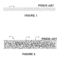
- Figure 1 is a schematic cross-sectional view of a NafionJ membrane 8 .
- Membrane 8 is a continuous sheet of ion-conducting material.
- NafionJ membranes are susceptible to mechanical failure and are difficult to work with, especially if they are very thin.
- Another problem with materials like NafionJ is that they are not dimensionally stable when used to conduct protons. Variations in water content of the membrane, which are inevitable during proton conduction, cause considerable shrinking and swelling. Electrochemical cells incorporating NafionJ membranes must be designed to accommodate such shrinking and swelling.
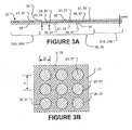
- Gore-SelectJ is a composite perfluorinated material consisting of a homogeneously porous substrate filled with an ion-conducting material.
- US patent No. 6,613,203 describes a membrane of this type.
- Figure 2 schematically depicts a Gore-SelectJ membrane 10 having a homogeneous substrate 12 filled with an ion-conducting material 14.
- Porous substrate 12 provides membrane 10 with some degree of structural integrity and dimensional stability, while ion-conducting filler 14 provides proton conductivity.
- ion-conducting membranes for use in electrochemical applications, such as fuel cells, electrolysis cells, chlor-alkali plants and the like, which possess advantageous mechanical properties and desirably high ion conductivity.
- a first aspect of the invention provides an ion-conducting membrane comprising an ion-conducting region.
- the ion-conducting region comprises a substrate having one or more ion-conducting passageways that extend through the substrate.
- Each passageway comprises an ion-conducting material that is relatively more ion conductive than the substrate.
- an ion-conducting membrane which comprises: a substrate penetrated by a plurality of openings in a porous region thereof; and an ion-conducting material which fills the openings to provide a plurality of ion-conducting passageways through the substrate.
- the ion-conducting material is relatively more ion conductive than the substrate.
- an ion-conducting membrane which comprises: a substrate penetrated by at least one opening; and an ion-conducting material which fills the at least one opening to provide an ion-conducting passageway through the substrate and which provides a first skin layer on a first side of the substrate, the skin layer extending transversely past a perimeter of the opening.
- the ion-conducting material is relatively more ion-conductive than the substrate.
- the ion-conducting region comprises a substrate having one or more ion-conducting passageways that extend through the substrate.
- the ion-conducting passageways are formed by selectively converting the substrate to a relatively more ion conductive state in locations corresponding to the ion-conducting passageways.
- Another aspect of the invention provides an electrochemical cell comprising an ion-conducting membrane in accordance with the invention.
- Another aspect of the invention provides a method for fabricating an ion-conducting membrane for use in an electrochemical cell.
- the method comprises: forming a plurality of openings which penetrate a sheet of substrate material at selected locations to create a porous region; and, filling the openings with an ion-conducting material to create a plurality of ion-conducting passageways through the substrate material.
- Another aspect of the invention provides a method for fabricating an ion-conducting membrane for use in an electrochemical cell.
- the method comprises selectively converting a sheet of substrate material to a relatively more ion conductive state in a plurality of locations to create a plurality of ion-conducting passageways through the sheet and to create an ion-conducting region in the sheet.
- Another aspect of the invention provides a method for fabricating an ion-conducting membrane for use in an electrochemical cell.
- the method comprises: forming at least one opening which penetrates a sheet of substrate material; and, filling the at least one opening with an ion-conducting material to create an ion-conducting passageway through the substrate material; and forming a first skin layer on a first side of the substrate, the skin layer extending transversely past a perimeter of the opening.
- Membranes suitable for use in electrochemical cells may be fabricated by providing a sheet of substrate material and forming one or more ion-conducting passageways through the sheet of substrate material.
- the ion-conducting passageway(s) have an ion conductivity greater than that of the surrounding substrate material.
- Ion-conducting passageway(s) may be formed by creating opening(s) which penetrate the substrate material and then filling the opening(s) with ion-conducting material and/or by selectively converting the substrate material to a relatively more ion conductive state in location(s) of the ion-conducting passageway(s).
- Mechanical and ion-conducting properties of the membranes can be made different in different regions by providing the ion-conducting passageway(s) with varying sizes, shapes, densities and/or arrangements.
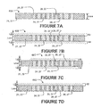
- FIG 3A is a schematic cross-sectional depiction of an ion-conducting membrane 20 according to a particular embodiment of the invention.
- Membrane 20 comprises one or more ion-conducting regions 33 and one or more non-ion-conducting regions 35A, 35B (collectively 35).
- Figure 3A shows a membrane 20 having one ion-conducting region 33 bordered by a pair of non-ion-conducting regions 35A, 35B.
- Membrane 20 comprises a substrate 21 of substrate material 22 and optionally comprises first and/or second skins 28, 29 on respective sides 32, 37 of substrate 21.
- Ion-conducting region 33 of membrane 20 comprises ion-conducting passageways 27 that extend from a first side 32 of substrate 21 to a second side 37 of substrate 21.
- Ion-conducting passageways 27 comprise an ion-conducting material 26 having an ion conductivity greater than that of the surrounding material (i.e. the material outside of ion-conducting passageways 27).
- ion-conducting material 26 is an ionomeric material.
- Optional skins 28, 29 may also comprise ion-conducting material 26.
- Ion-conducting passageway(s) 27 may be formed by creating opening(s) 24 which penetrate a substrate material 22 and then filling the opening(s) 24 with ion-conducting material 26 and/or by selectively converting substrate material 22 to a relatively more ion conductive state in location(s) of ion-conducting passageway(s). Both of these fabrication techniques are discussed in more detail below.
- membrane 20 comprises a substrate 21 made of a substrate material 22. Openings 24 are formed to penetrate substrate 21 at selected locations. Openings 24 may be micro-structures.
- a Amicro-structure@ is a structure capable of being revealed by a microscope having a magnification of 5 times or more. Openings 24 need not be micro-structures. In some embodiments, openings 24 are larger.
- Openings 24 provide substrate 21 with one or more porous regions 30 which are relatively more porous than surrounding regions 31A, 31B.
- Each porous region 30 of substrate 21 comprises a plurality of openings 24 and corresponds with an ion-conducting region 33 of membrane 20.
- Non-porous regions 31A, 31B (collectively, 31) respectively correspond to non-ion-conducting regions 35A, 35B of membrane 20.
- Substrate material 22 may comprise any suitable material or combination of materials that provides a substantial barrier to the reactants with which membrane 20 will be used.
- a membrane for use in a hydrogen/air fuel cell is preferably substantially impermeable to hydrogen and oxygen gases.
- Substrate material 22 may comprise, for example, a material selected from:
- openings 24 are filled with an ion-conducting material 26 to form ion-conducting passageways 27 that extend through membrane 20 from a first side 32 of substrate 21 to a second side 37 of substrate 21.
- Ion-conducting material 26 is relatively more ion-conductive than the surrounding substrate material 22.
- passageways 27 each have a path length equal to the thickness L core of substrate 21.
- passageways 27 have tortuosity factors of 1, where tortuosity is equal to the distance that a particle must travel to pass through substrate 21 divided the thickness (L core ) of substrate 21.
- Openings 24 may be formed in substrate 21 using any suitable method.
- openings 24 may be formed through substrate 21 by:
- passageways 27 are formed in the shape of slits in openings 24 made using conventional sheet conversion methods.
- Passageways 27 may be round or may have other shapes, such as cross shapes, hexagonal shapes, oval-shapes, elliptical shapes or star shapes.
- passageways 27 are formed in ordered arrangements, as opposed to placed at random locations. Any suitable patterns may be used. For example, passageways 27 may be located at nodes of:
- Figure 3B is a partial cross-sectional view of ion-conducting region 33 of membrane 20 along the line 3-3 (see Figure 3A ) in accordance with a particular embodiment of the invention.
- ion-conducting passageways 27 are circular in transverse cross-section and are arranged in a rectangular array.
- the parameter D is used to denote the widest transverse dimension of ion-conducting passageways 27.
- passageways 27 are all the same size and the parameter D is equal to the diameter of the openings 24 in which passageways 27 are formed.
- the parameter L denotes the center-to-center transverse spacing of the nearest adjacent ion-conducting passageways 27.
- Figure 3C depicts a partial cross-sectional view of ion-conducting region 33 of membrane 20 along the line 3-3 (see Figure 3A ) according to another embodiment of the invention.
- ion-conducting passageways 27 are hexagonal in transverse cross-section and are arranged in a hexagonal packing array.
- the parameters D (i.e. the widest dimension of passageways 27) and L (i.e. the center-to-center spacing between nearest adjacent passageways 27) are also illustrated in Figure 3C .
- the parameter D of passageways 27 is 200 microns or less. In other embodiments, the parameter D of passageways 27 is 2500 microns or less. In some embodiments, passageways 27 have cross-sectional areas not exceeding 5x10 -8 m 2 . In other embodiments, passageways 27 have cross-sectional areas not exceeding 1H10 -5 m 2 . In some embodiments, ion-conducting passageways 27 have a minimum transverse dimension of at least 25 microns. In other embodiments, ion-conducting passageways 27 have a minimum transverse dimension of at least 50 microns. In some embodiments, the parameter L of passageways 27 is 500 microns or less in at least some areas of porous region 30. In other embodiments, the parameter L of passageways 27 is 5000 microns or less in at least some areas of porous region 30.
- membranes according to the invention are constructed having a parameter ratio L/D not exceeding 2.5 in one or more ion-conducting regions. In other embodiments, membranes according to the invention are constructed having a parameter ratio L/D not exceeding 1.5.
- ratio parameter ⁇ may be used to characterize conducting regions of membranes according to the invention.
- the ratio parameter ⁇ may be defined as the ratio of the total transverse area of an ion-conducting region to the total transverse area of the ion-conducting passageways 27 within the ion-conducting region.
- membranes according to the invention are constructed having a parameter ratio ⁇ not exceeding 2.5 in one or more ion-conducting regions. In other embodiments, membranes according to the invention are constructed having a parameter ratio ⁇ not exceeding 1.5.
- Substrate 21 provides structural support for ion-conducting material 26 and overall structural support for membrane 20 (see Figure 3A ).
- the mechanical properties of substrate 21 can be selected to match the mechanical properties desired for particular applications. For example, by varying the density, size, shape and/or arrangement of openings 24 in different regions of substrate 21, one can provide different mechanical properties and/or different ion-conducting properties in those different regions.
- FIG 4 shows a planar sheet 34 of substrate material 22 according to a particular embodiment of the invention.
- Sheet 34 may be used as a substrate 21 of an ion-conducting membrane 20 of the type shown in Figure 3A for use in an electrochemical cell, such as a fuel cell.
- sheet 34 is fabricated from a thin sheet of substrate material 22 and is divided into perimeter (non-porous) seal region 31, which surrounds porous region 30.
- Porous region 30 has openings 24 which penetrate sheet 34.
- ions may be conducted through openings 24 of porous region 30, while perimeter seal region 31 provides structural strength in the vicinity of the fuel cell's compressive seals.
- porous region 30 It is not necessary that porous region 30 be uniformly porous. In some cases, it is advantageous to vary characteristics of openings 24 (e.g. size, shape, density and/or arrangement of openings 24) and/or the parameters associated with openings 24 (e.g. L, D, L/D and/or ⁇ ) across a porous region, such as region 30. In some cases, it is advantageous to provide a substrate 21 with a plurality of porous regions. The characteristics of openings 24 and parameters associated with openings 24 may be different in each such porous region.
- characteristics of openings 24 e.g. size, shape, density and/or arrangement of openings 24
- the parameters associated with openings 24 e.g. L, D, L/D and/or ⁇
- openings 24 may be made relatively small and/or the density of openings 24 may be made relatively low.
- the parameter ratio L/D and/or the parameter ⁇ may be made relatively large.
- the parameter ratio L/D and/or the parameter ⁇ may be greater than 5.
- openings 24 may be made relatively large and/or the density of openings 24 may be made relatively high.
- the parameter ratio L/D and/or the parameter ⁇ may be made relatively low.
- the parameter ratio L/D and/or the parameter ⁇ may be less than 3.
- Such regions may provide relatively high proton conductivity at the expense of mechanical strength. Using these techniques, it is possible tune the performance (i.e. mechanical strength and proton conductivity) over the spatial dimensions of a fuel cell membrane.
- FIG. 5 shows a planar sheet 40 of substrate material 22 according to another example embodiment of the invention.
- Sheet 40 may be used as a substrate 21 of an ion-conducting membrane 20 of the type shown in Figure 3A for use in a fuel cell.
- Sheet 40 is formed from a substrate material 22 and comprises: a non-porous perimeter region 44, a first porous region 46, a second porous region 48, and a third porous region 49.
- Porous regions 46, 48, and 49 each have openings 24. The characteristics of openings 24 and/or the parameters associated with openings 24 in porous regions 46, 48, 49 differ from one another.
- the size of their openings 24, the density of openings 24, the shape of openings 24 and/or the arrangement or openings 24 vary between porous regions 46, 48, 49.
- the size and shape of openings 24 varies between porous regions 46, 48, 49.
- the characteristics of openings 24 e.g. density, size, shape and/or arrangement
- the parameters of openings 24 e.g. L, D, L/D and/or ⁇
- the parameter ratio L/D and/or the parameter ⁇ of openings 25 may vary in accordance with a smooth function such as a bell curve.
- a sheet of substrate material 22 may be fabricated to have openings 24 of uniform characteristics and/or parameters over the entire sheet of substrate material 22. Openings 24 are described herein as having various characteristics, such as size, shape, density, arrangement and various parameters, such as L, D, minimum transverse dimension, L/D and ⁇ . Any of these characteristics and/or parameters may also be used to describe ion-conducting passageways generally.
- ion-conducting membranes comprise composite substrates made of multiple layers of different materials. Some layers of a composite substrate may be porous. For example, one or more layers of a composite substrate may comprise a mesh material. Other layers of such a composite substrate may comprise ion-conducting regions and ion-nonconducting regions according to a suitable one of the constructions described herein. A composite substrate fabricated in this manner may have superior mechanical strength.
- FIG. 6 is an exploded view of a composite substrate 50 in accordance with a particular embodiment of the invention.
- Composite substrate 50 comprises a first layer 52.
- Layer 52 may comprise a substrate layer similar to any of those described above, for example.
- layer 52 comprises a non-porous region 31 which surrounds a porous region 30 having openings 24 formed therein.
- Intermediate layer 54 comprises a mesh-like structure bonded to first layer 52 to provide structural reinforcement.
- Optional backing layer 56 may form a lamination, so that intermediate layer 54 is encapsulated between layers 52 and 56.
- a composite substrate may have more than 2 or 3 layers of substrate precursor materials.
- Ion-conducting materials such as ionomers
- Ion-conducting materials can be deposited into porous regions of such substrates to form ion-conducting membranes having ion-conducting passageways for use in fuel cells, electrolysis cells and the like.
- Ion-conducting materials may be deposited in various arrangements on such substrates to make ion-conducting membranes according to the invention.
- Figures 7A, 7B, 7C and 7D show cross-sections of a number of exemplary ion-conducting membranes according to various embodiments of the invention. Ion-conducting material is arranged differently in each of the membranes depicted in Figures 7A, 7B, 7C and 7D.
- Figure 7A shows a membrane 60A comprising a substrate 21 formed from a substrate material 22. Substrate 21 has openings 24 formed therein. Openings 24 of membrane 60A are filled with ion-conducting material 26 to form ion-conducting passageways 27 through membrane 60A. Ion-conducting material 26 is relatively more ion-conductive than substrate material 22.
- the thickness of the ion-conducting material 26 and the length of ion-conducting passageways 27 are substantially similar to the thickness L core of substrate 21. In other embodiments, the thickness of ion-conducting material 26 (and the ion-conducting passageways 27) differ from the thickness L core of substrate 21.
- FIG. 7B shows a membrane 60B according to another embodiment of the invention.
- Membrane 60B has openings 24 filled with ion-conducting material 26 to form ion-conducting passageways 27.
- Membrane 60B also comprises ion-conducting skins 62, 64 which coat substrate material 22 on either side thereof.
- the ion-conducting material in each of skins 62, 64 may the same or different and may be the same as or different than the ion-conducting material 26 in openings 24.
- the ion-conducting material in each of skins 62, 64 is relatively more ion conductive than substrate material 22.
- the thickness L skin of each skin 62, 64 is substantially similar. In other embodiments, the thicknesses of skins 62, 64 differ from one another.
- Coating substrate 21 with skins 62, 64 is optional.
- the provision of skins 62, 64 may be advantageous in that skins 62, 64 can provide ion-conducting passageways between non-porous regions and porous regions of substrate 21 (i.e. between ion-conducting and non-ion-conducting regions of membrane 60B) and between non-porous regions on opposing sides of substrate 21 (i.e. between non-ion-conducting regions on either side of membrane 60B).
- Figure 7C shows a membrane 60C comprising a substrate 21 having openings 24 filled with ion-conducting material 26 to form ion-conducting passageways 27.
- Substrate 21 is coated with ion-conducting skins 62, 64.
- skins 62, 64 extend transversely over the porous region of substrate 21 and slightly into the non-porous region of substrate 21.
- skins 62, 64 extend transversely over only a part of the porous region of substrate 21.
- skins 62, 62 extend transversely over only the porous region of substrate 21 and do not extend transversely into the non-porous region of substrate 21.
- Figure 7D shows a membrane 60D comprising a substrate material 22 having openings 24 filled with ion-conducting material 26 to form ion-conducting passageways 27 and a single ion-conducting skin 62 which coats only one side of substrate 21.
- Skin 62 may have different transverse extension characteristics as described above.
- FIG. 8A shows an ion-conducting membrane 70A according to another embodiment of the invention.
- Membrane 70A comprises a substrate 21 made of substrate material 22 with openings 24 formed at selected locations as described above.
- Substrate 21 supports a plurality of ion-conducting materials of different compositions.
- membrane 70A comprises three layers of ion-conducting material including: a skin layer 62 of a first ion-conducting material 72 on a first side 73 of membrane 70A; a mid layer of a second ion-conducting material 26 different from first material 72; and a skin layer 64 of a third ion-conducting material 76 different from second material 26 (and optionally different from both first material 72 and second material 26) on a second side 77 of membrane 70A.
- Ion-conducting materials 72, 26, 76 are relatively more ion conductive than substrate material 22.
- skins 62, 64 both have approximately equal thickness (L skin ), but this is not necessary.
- FIG. 8B shows an ion-conducting membrane 70B according to another embodiment of the invention.
- Membrane 70B has two ion-conducting layers 78, 79 of different ion-conducting materials.
- the ion-conducting material of layers 78, 79 is relatively more ion-conductive than substrate material 22.
- Ion-conducting material(s) may be deposited onto and into a substrate to make an ion-conducting membrane according to the invention in any of a variety of methods including casting, dipping, printing, syringe injection and molding. Further, when one or more skins are used, it is possible to fabricate a membrane by bonding a substrate having a porous region to a pre-formed sheet of ion-conducting material (i.e. a skin) or between two pre-formed sheets of ion-conducting material. A membrane may also be formed by bonding ion-conducting sheets (skins) to a liquid precursor.
- Figures 9A and 9B schematically depict the fabrication of an ion-conducting membrane according to a particular embodiment of the invention.
- Figure 9A depicts the formation of a substrate 80.
- Substrate 80 comprises a substrate material 22 in which openings 24 have been formed at selected locations as described above to provide porous region 30 and non-porous regions 31A, 31B on either side thereof.
- each of non-porous regions 31A, 31B is provided with one or more optional fabrication vias 82A, 82B.
- Fabrication vias 82A, 82B may be formed in the same manner as openings 24.
- Fabrication vias 82A, 82B are preferably spaced apart from porous region 30.
- fabrication vias 82 are formed at locations that are transversely spaced apart from corresponding porous region(s) 30 by a distance of at least 12 L , where L is the center to center transverse spacing between nearest adjacent openings 24 in corresponding porous region(s) 30.
- fabrication vias 82 are formed a locations that are transversely spaced apart from corresponding porous region(s) 30 by a distance of at least 3L.
- Figure 9B depicts the addition of ion-conducting material 26 to substrate 80 to form ion-conducting membrane 84 having ion-conducting passageways 27.
- Ion-conducting material 26 is relatively more ion-conductive than substrate material 22.
- ion-conducting material 26 is applied in such a manner (e.g. by casting) that ion-conducting material 26 coats substrate 80, filling openings 24, filling optional fabrication vias 82A, 82B (as indicated at 86A, 86B) and forming ion-conducting skins 62, 64.
- Optional fabrication vias 82A, 82B may provide an advantage in that when ion-conducting material 26 is applied it may be in a liquid form.
- Ion-conducting material 86A, 86B in fabrication vias 82A, 82B may act like anchors which provide ion-conducting material 26 with tensile strength, thereby tending to prevent deformation of ion-conducting material 26 during drying.
- fabrication vias 82A, 82B may improve the uniformity of skins 62, 64. Bonds between skins 62, 64 and substrate 80 (for example, at locations 83, 85) may also add tensile strength to ion-conducting material 26 and thereby reduce deformation of ion-conducting material 26 when drying.
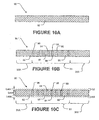
- FIGS. 9C and 9D schematically depict different cross-sectional views of an ion-conducting membrane fabricated according to another embodiment of the invention.
- Substrate 120 comprises a substrate material 22 in which an opening 122 has been formed. Opening 122 preferably comprises a smoothly curved perimeter as shown Figure 9D to avoid stress concentrations.
- Non-porous region(s) 31 adjacent opening 122 may be provided with one or more optional fabrication vias 82A, 82B (collectively, 82).
- Fabrication vias 82 may be formed in any suitable manner as described above and are preferably spaced apart from opening 122.
- fabrication vias 82 are formed a locations that are transversely spaced apart from corresponding opening 122 by a distance of at least 100 microns. In other embodiments, fabrication vias 82 are formed at locations that are transversely spaced apart from opening 122 by a distance of at least 200 microns.
- Ion-conducting material 26 is added to substrate 120 to form ion-conducting membrane 124 having an ion-conducting passageway 27.
- Ion-conducting material 26 is relatively more ion-conductive than substrate material 22.
- ion-conducting material 26 is applied in such a manner (e.g. by casting) that ion-conducting material 26 coats substrate 120, filling opening 122, filling optional fabrication vias 82 (as indicated at 86A, 86B (collectively, 86)) and forming ion-conducting skins 62, 64.
- fabrication vias 82 may act like anchors which secure ion-conducting material 26 around the edges of opening 122. Providing such anchors can help to prevent deformation of ion-conducting material 26 during drying and makes the overall structure more rugged. Whether or not fabrication vias 82 are present, bonds between skins 62, 64 and non-porous region(s) 31 of substrate 120 (for example, at locations 83, 85) may permit adhesion of ion-conducting material 26 around the edges of opening 122 that is adequate for some applications.
- the membranes described above may be formed by applying an ion-conducting material 26 to a substrate 21 in which openings 24 have been formed. Ion-conducting material 26 fills openings 24 (thereby providing ion-conducting passageways 27) and optionally provides ion-conducting skins 62, 64.
- ion-conducting membranes are fabricated by providing a sheet of substrate material and selectively converting the substrate material into a relatively ion-conducting state at selected locations to form ion-conducting passageways or by providing a sheet of ion-conducting substrate material and selectively converting the ion-conducting material to a relatively non-ion-conducting state at selected locations to form ion-conducting passageways.
- Figures 10A-10C schematically depict the fabrication of an ion-conducting membrane according to another embodiment of the invention.
- Figure 10A depicts a sheet 90 of a substrate material 92.
- Substrate material 92 is preferably melt processable.
- substrate material 92 comprises a resin precursor to NafionJ which may be a copolymer of tetrafluoroethlyene and perfluoro-3, 6-dioxa-4-methyl-7-octenesulfonyl fluoride.
- Substrate material 92 is convertible in selected locations to a relatively ion-conducting state.
- the resin precursor to NafionJ is convertible in selected locations to NafionJ, which conducts ions.
- Figure 10B depicts the conversion of substrate material 92 into a relatively ion-conducting state 94 in selected locations to form ion-conducting passageways 96.
- Ion-conducting passageways 96 provide ion-conduction paths through substrate sheet 90.
- Ion-conducting passageways 96 may be arranged in any suitable arrangement.
- ion-conducting passageways 96 may be configured and arranged in any of the ways described above in relation to passageways 27.
- Sheet 90 may be described as having one or more ion-conducting region(s) 33 (i.e. in a vicinity of ion-conducting passageways 96) and one or more non-ion-conducting regions 35.
- Each of ion-conducting regions 33 comprises an array of ion-conducting passageways 96.
- non-ion-conducting regions 35A, 35B are located on either side of ion-conducting region 33.
- Substrate material 92 may be converted to a relatively ion-conducting state to form ion-conducting passageways 96 using any suitable technique.
- ion-conducting passageways 96 may be formed by selectively exposing areas of substrate sheet 90 to chemicals, radiation, heat or the like. Masks may be used to selectively expose areas of substrate sheet 90 to chemicals, radiation, heat or the like. Other lithographic, etching and or printed circuit board fabrication techniques may also be used.
- non-ion-conducting material 92 is a resin precursor to NafionJ
- conversion of non-ion-conducting material 92 into an ion-conducting material 94 in the selected locations of ion-conducting passageways 96 may comprise masking sheet 90 and selectively hydrolyzing areas of sheet 90 by exposure to water.
- Ion-conducting membranes formed by selective conversion of a substrate material may be tailored to provide different spatial membrane regions with different ion conductivity and/or mechanical characteristics to suit particular applications.
- ion-conducting passageways 96 formed by selective conversion may be formed to have characteristics (e.g. size, shape, density and/or arrangement) and/or parameters (e.g. L, D, L/D, ⁇ ) similar to openings 24 (and/or ion-conducting passageways 27) described above.
- Ion-conducting passageways 96 may have different characteristics and/or parameters in different regions of sheet 90. Such different characteristics and/or parameters may vary smoothly or may vary discretely.
- Sheet 90 may be fabricated from a plurality of layers in accordance with the embodiments described above. One or more layers may be added to sheet 90 as described above.
- Figure 10C depicts the application of optional skins 62, 64 of ion-conducting material to sheet 90.
- Skins 62, 64 may be applied using any of the techniques described above, for example.
- the optimum skin layer thickness L skin is in a range of 5-50 microns. In some embodiments, the optimum skin layer thickness L skin is in a range of 0.25 to 5 times the thickness of the core layer L core .
- ion-conducting membranes disclosed above are capable of providing desired conductivity, gas permeability and mechanical strength characteristics that can be varied at the designer's discretion over the spatial extent of the membrane. This affords a designer great design flexibility and allows the local tuning of mechanical and electrical parameters to best meet the competing needs of ion conductivity and mechanical strength within a fuel cell or similar system.
- the invention may be provided in the form of electrochemical cells of any suitable type which incorporate membranes according to the invention. Some embodiments of the invention provide fuel cells or membrane-electrode assemblies for fuel cells.
Abstract
Description
- The subject matter of this application is related to that of a co-owned application entitled AELECTROCHEMICAL CELLS HAVING CURRENT CARRYING STRUCTURES UNDERLYING ELECTROCHEMICAL REACTION LAYERS@ filed concurrently herewith and a co-owned application entitled AELECTROCHEMICAL CELLS FORMED ON PLEATED SUBSTRATES@ filed concurrently herewith, both of which are hereby incorporated by reference herein. This application claims priority from United States Patent Application No.
60/567437 filed on 4 May 2004 11/047558 filed on 2 February 2005 - This invention relates to electrochemical cells, such as fuel cells, electrolysis cells and the like which incorporate ion-conducting membranes. Particular embodiments of the invention provide ion-conducting membranes for use in such cells.
- Ion-conducting membranes, including ionomeric membranes such as NafionJ, are an important component in membrane separation processes and electrochemical reactor systems including chlor-alkali cells, electrolysis cells and fuel cells. Such membranes act as ion conductors while preventing reactants from inter-mixing. In some applications, the ions conducted by such membranes are protons. The availability of materials which are solid and can conduct protons has allowed a breakthrough in the production of simple and robust fuel cell devices.
- In typical prior art fuel cells, the ion-conducting membrane is an ionomeric membrane that fulfills several functions including providing ion conductivity, providing a barrier between reactants and providing a structural spacer that withstands the clamping forces necessary to seal the fuel cell.
- The design of ion-conducting membranes for use in electrochemical cells typically requires balancing between two competing design objectives. Firstly, it is generally desirable to maximize the conductivity of the ion-conducting membrane to minimize operational losses. This first obj ective tends to favor ion-conducting materials which have high water contents and therefore approach liquid form. Secondly, it is generally desirable to provide a membrane that is robust and usable as a structural material within the cell to maintain integrity of the cell in the presence of differential pressures across the membrane. This second objective tends to favor ion-conducting materials which are solid and have high strength. It will be appreciated that these two design objectives often conflict with one another. Current practices for designing electrochemical cells involve making compromises between these design obj ectives.
- An example of an ion-conducting material is NafionJ, which is typically provided in the form of sheets that may be as thin as 25 microns.
Figure 1 is a schematic cross-sectional view of a NafionJ membrane 8. Membrane 8 is a continuous sheet of ion-conducting material. NafionJ membranes are susceptible to mechanical failure and are difficult to work with, especially if they are very thin. Another problem with materials like NafionJ is that they are not dimensionally stable when used to conduct protons. Variations in water content of the membrane, which are inevitable during proton conduction, cause considerable shrinking and swelling. Electrochemical cells incorporating NafionJ membranes must be designed to accommodate such shrinking and swelling. - Gore-SelectJ is a composite perfluorinated material consisting of a homogeneously porous substrate filled with an ion-conducting material.
US patent No. 6,613,203 describes a membrane of this type.Figure 2 schematically depicts a Gore-SelectJ membrane 10 having ahomogeneous substrate 12 filled with an ion-conductingmaterial 14.Porous substrate 12 providesmembrane 10 with some degree of structural integrity and dimensional stability, while ion-conductingfiller 14 provides proton conductivity. - There remains a need for ion-conducting membranes for use in electrochemical applications, such as fuel cells, electrolysis cells, chlor-alkali plants and the like, which possess advantageous mechanical properties and desirably high ion conductivity.
- A first aspect of the invention provides an ion-conducting membrane comprising an ion-conducting region. The ion-conducting region comprises a substrate having one or more ion-conducting passageways that extend through the substrate. Each passageway comprises an ion-conducting material that is relatively more ion conductive than the substrate.
- Another aspect of the invention provides an ion-conducting membrane which comprises: a substrate penetrated by a plurality of openings in a porous region thereof; and an ion-conducting material which fills the openings to provide a plurality of ion-conducting passageways through the substrate. The ion-conducting material is relatively more ion conductive than the substrate.
- Another aspect of the invention provides an ion-conducting membrane, which comprises: a substrate penetrated by at least one opening; and an ion-conducting material which fills the at least one opening to provide an ion-conducting passageway through the substrate and which provides a first skin layer on a first side of the substrate, the skin layer extending transversely past a perimeter of the opening. The ion-conducting material is relatively more ion-conductive than the substrate.
- Another aspect of the invention provides an ion-conducting membrane comprising an ion-conducting region. The ion-conducting region comprises a substrate having one or more ion-conducting passageways that extend through the substrate. The ion-conducting passageways are formed by selectively converting the substrate to a relatively more ion conductive state in locations corresponding to the ion-conducting passageways.
- Another aspect of the invention provides an electrochemical cell comprising an ion-conducting membrane in accordance with the invention.
- Another aspect of the invention provides a method for fabricating an ion-conducting membrane for use in an electrochemical cell. The method comprises: forming a plurality of openings which penetrate a sheet of substrate material at selected locations to create a porous region; and, filling the openings with an ion-conducting material to create a plurality of ion-conducting passageways through the substrate material.
- Another aspect of the invention provides a method for fabricating an ion-conducting membrane for use in an electrochemical cell. The method comprises selectively converting a sheet of substrate material to a relatively more ion conductive state in a plurality of locations to create a plurality of ion-conducting passageways through the sheet and to create an ion-conducting region in the sheet.
- Another aspect of the invention provides a method for fabricating an ion-conducting membrane for use in an electrochemical cell. The method comprises: forming at least one opening which penetrates a sheet of substrate material; and, filling the at least one opening with an ion-conducting material to create an ion-conducting passageway through the substrate material; and forming a first skin layer on a first side of the substrate, the skin layer extending transversely past a perimeter of the opening.
- Further features and applications of specific embodiments of the invention are described below.
- In drawings which illustrate non-limiting embodiments of the invention:
-
Figure 1 is a cross-sectional schematic view of a sheet of ion-conducting material of the type commonly employed in prior art fuel cells; -
Figure 2 is a cross-sectional schematic view of a prior art composite membrane having a homogeneously porous substrate filled with ion-conducting material; -
Figure 3A is a cross-sectional schematic view of an ion-conducting membrane according to a particular embodiment of the invention; -
Figure 3B is a partial transverse cross-sectional view of the ion-conducting region of theFigure 3A membrane taken along the line 3-3 (seeFigure 3A ) in accordance with a particular embodiment of the invention; -
Figure 3C is a partial transverse cross-sectional view of the ion-conducting region of theFigure 3A membrane taken along the line 3-3 (seeFigure 3A ) in accordance with another embodiment of the invention; -
Figure 4 is a perspective view of a sheet of substrate material which may be used in a membrane of the type shown inFigure 3A according to a particular embodiment of the invention; -
Figure 5 is a perspective view of a sheet of substrate material which may be used in a membrane of the type shown inFigure 3A according to another embodiment of the invention; -
Figure 6 is an exploded perspective view of a substrate made from a lamination of multiple sheets of precursor materials which may be used in a membrane of the type shown inFigure 3A according to another embodiment of the invention; -
Figures 7A-7D are cross-sectional schematic views of ion-conducting membranes according to various embodiments of the invention; -
Figures 8A-8B are cross-sectional schematic views of ion-conducting membranes in which multiple different ion-conducting materials are applied in layers to form a composite membrane structure; -
Figures 9A and 9B schematically depict the fabrication of an ion-conducting membrane according to a particular embodiment of the invention; -
Figure 9C and 9D schematically depict different cross-sectional views of an ion-conducting membrane fabricated according to another embodiment of the invention; and -
Figures 10A-10C schematically depict the fabrication of an ion-conducting membrane according to another embodiment of the invention. - Throughout the following description, specific details are set forth in order to provide a more thorough understanding of the invention. However, the invention may be practiced without these particulars. In other instances, well known elements have not been shown or described in detail to avoid unnecessarily obscuring the invention. Accordingly, the specification and drawings are to be regarded in an illustrative, rather than a restrictive, sense.
- Membranes suitable for use in electrochemical cells may be fabricated by providing a sheet of substrate material and forming one or more ion-conducting passageways through the sheet of substrate material. The ion-conducting passageway(s) have an ion conductivity greater than that of the surrounding substrate material. Ion-conducting passageway(s) may be formed by creating opening(s) which penetrate the substrate material and then filling the opening(s) with ion-conducting material and/or by selectively converting the substrate material to a relatively more ion conductive state in location(s) of the ion-conducting passageway(s). Mechanical and ion-conducting properties of the membranes can be made different in different regions by providing the ion-conducting passageway(s) with varying sizes, shapes, densities and/or arrangements.
-
Figure 3A is a schematic cross-sectional depiction of an ion-conductingmembrane 20 according to a particular embodiment of the invention.Membrane 20 comprises one or more ion-conductingregions 33 and one or more non-ion-conductingregions Figure 3A shows amembrane 20 having one ion-conductingregion 33 bordered by a pair of non-ion-conductingregions Membrane 20 comprises asubstrate 21 ofsubstrate material 22 and optionally comprises first and/orsecond skins respective sides substrate 21. - Ion-conducting
region 33 ofmembrane 20 comprises ion-conducting passageways 27 that extend from afirst side 32 ofsubstrate 21 to asecond side 37 ofsubstrate 21. Ion-conducting passageways 27 comprise an ion-conductingmaterial 26 having an ion conductivity greater than that of the surrounding material (i.e. the material outside of ion-conducting passageways 27). In some embodiments, ion-conductingmaterial 26 is an ionomeric material.Optional skins material 26. - Ion-conducting passageway(s) 27 may be formed by creating opening(s) 24 which penetrate a
substrate material 22 and then filling the opening(s) 24 with ion-conductingmaterial 26 and/or by selectively convertingsubstrate material 22 to a relatively more ion conductive state in location(s) of ion-conducting passageway(s). Both of these fabrication techniques are discussed in more detail below. - In accordance with one embodiment of the invention,
membrane 20 comprises asubstrate 21 made of asubstrate material 22.Openings 24 are formed to penetratesubstrate 21 at selected locations.Openings 24 may be micro-structures. In this disclosure, a Amicro-structure@ is a structure capable of being revealed by a microscope having a magnification of 5 times or more.Openings 24 need not be micro-structures. In some embodiments,openings 24 are larger. -
Openings 24 providesubstrate 21 with one or moreporous regions 30 which are relatively more porous than surroundingregions porous region 30 ofsubstrate 21 comprises a plurality ofopenings 24 and corresponds with an ion-conductingregion 33 ofmembrane 20.Non-porous regions regions membrane 20. In theFigure 3A embodiment, there are noopenings 24 formed innon-porous regions substrate 21. -
Substrate material 22 may comprise any suitable material or combination of materials that provides a substantial barrier to the reactants with whichmembrane 20 will be used. For example, a membrane for use in a hydrogen/air fuel cell is preferably substantially impermeable to hydrogen and oxygen gases.Substrate material 22 may comprise, for example, a material selected from: - $ polyamide films,
- $ polyimide films, such as KaptonJ,
- $ polyethylene films,
- $ TeflonJ films,
- $ films comprising other polymers,
- $ a resin precursor to hydrolyzed NafionJ,
- $ non-polymer materials such as silicon or glass.
- In porous region(s) 30 of
substrate 21,openings 24 are filled with an ion-conductingmaterial 26 to form ion-conducting passageways 27 that extend throughmembrane 20 from afirst side 32 ofsubstrate 21 to asecond side 37 ofsubstrate 21. Ion-conductingmaterial 26 is relatively more ion-conductive than the surroundingsubstrate material 22. In the illustrated embodiment, passageways 27 each have a path length equal to the thickness Lcore ofsubstrate 21. In other words, passageways 27 have tortuosity factors of 1, where tortuosity is equal to the distance that a particle must travel to pass throughsubstrate 21 divided the thickness (Lcore) ofsubstrate 21. -
Openings 24 may be formed insubstrate 21 using any suitable method. By way of non-limiting example,openings 24 may be formed throughsubstrate 21 by: - X
- chemical etching;
- X
- laser micromachining;
- X
- laser drilling;
- X
- mechanical drilling;
- X
- milling;
- X
- punching;
- X
- calendaring;
- X
- printed circuit board fabrication techniques;
- X
- lithographic fabrication techniques;
- X
- mechanical dies; and
- X
- the like.
- The dimensions of passageways 27, the spacing between passageways 27, the shapes of passageways 27 and the arrangement of passageways 27 can be selected to suit particular applications and may be influenced by cost factors. In one particular example, passageways 27 are formed in the shape of slits in
openings 24 made using conventional sheet conversion methods. Passageways 27 may be round or may have other shapes, such as cross shapes, hexagonal shapes, oval-shapes, elliptical shapes or star shapes. - In preferred embodiments, passageways 27 are formed in ordered arrangements, as opposed to placed at random locations. Any suitable patterns may be used. For example, passageways 27 may be located at nodes of:
- $ a square or rectangular array;
- $ a triangular array;
- $ a hexagonal array; or,
- $ any other suitable arrangement.
-
Figure 3B is a partial cross-sectional view of ion-conductingregion 33 ofmembrane 20 along the line 3-3 (seeFigure 3A ) in accordance with a particular embodiment of the invention. In this embodiment, ion-conducting passageways 27 are circular in transverse cross-section and are arranged in a rectangular array. - The parameter D is used to denote the widest transverse dimension of ion-conducting passageways 27. In the
Figure 3B embodiment, passageways 27 are all the same size and the parameter D is equal to the diameter of theopenings 24 in which passageways 27 are formed. The parameter L denotes the center-to-center transverse spacing of the nearest adjacent ion-conducting passageways 27. -
Figure 3C depicts a partial cross-sectional view of ion-conductingregion 33 ofmembrane 20 along the line 3-3 (seeFigure 3A ) according to another embodiment of the invention. In theFigure 3C embodiment, ion-conducting passageways 27 are hexagonal in transverse cross-section and are arranged in a hexagonal packing array. The parameters D (i.e. the widest dimension of passageways 27) and L (i.e. the center-to-center spacing between nearest adjacent passageways 27) are also illustrated inFigure 3C . - In some embodiments, the parameter D of passageways 27 is 200 microns or less. In other embodiments, the parameter D of passageways 27 is 2500 microns or less. In some embodiments, passageways 27 have cross-sectional areas not exceeding 5x10⁻⁸ m2. In other embodiments, passageways 27 have cross-sectional areas not exceeding 1H10-5 m2. In some embodiments, ion-conducting passageways 27 have a minimum transverse dimension of at least 25 microns. In other embodiments, ion-conducting passageways 27 have a minimum transverse dimension of at least 50 microns. In some embodiments, the parameter L of passageways 27 is 500 microns or less in at least some areas of
porous region 30. In other embodiments, the parameter L of passageways 27 is 5000 microns or less in at least some areas ofporous region 30. - For maximum conductivity through
membrane 20, it is desirable for the parameter ratio L/D to be as close to unity as possible. In some embodiments, membranes according to the invention are constructed having a parameter ratio L/D not exceeding 2.5 in one or more ion-conducting regions. In other embodiments, membranes according to the invention are constructed having a parameter ratio L/D not exceeding 1.5. - Another ratio parameter γ may be used to characterize conducting regions of membranes according to the invention. The ratio parameter γ may be defined as the ratio of the total transverse area of an ion-conducting region to the total transverse area of the ion-conducting passageways 27 within the ion-conducting region. In some embodiments, membranes according to the invention are constructed having a parameter ratio γ not exceeding 2.5 in one or more ion-conducting regions. In other embodiments, membranes according to the invention are constructed having a parameter ratio γ not exceeding 1.5.
-
Substrate 21 provides structural support for ion-conductingmaterial 26 and overall structural support for membrane 20 (seeFigure 3A ). The mechanical properties ofsubstrate 21 can be selected to match the mechanical properties desired for particular applications. For example, by varying the density, size, shape and/or arrangement ofopenings 24 in different regions ofsubstrate 21, one can provide different mechanical properties and/or different ion-conducting properties in those different regions. -
Figure 4 shows aplanar sheet 34 ofsubstrate material 22 according to a particular embodiment of the invention.Sheet 34 may be used as asubstrate 21 of an ion-conductingmembrane 20 of the type shown inFigure 3A for use in an electrochemical cell, such as a fuel cell. In theFigure 4 embodiment,sheet 34 is fabricated from a thin sheet ofsubstrate material 22 and is divided into perimeter (non-porous)seal region 31, which surroundsporous region 30.Porous region 30 hasopenings 24 which penetratesheet 34. When a fuel cell having an ion-conductingmembrane 20 is constructed usingsheet 34 as asubstrate 21, ions may be conducted throughopenings 24 ofporous region 30, whileperimeter seal region 31 provides structural strength in the vicinity of the fuel cell's compressive seals. - It is not necessary that
porous region 30 be uniformly porous. In some cases, it is advantageous to vary characteristics of openings 24 (e.g. size, shape, density and/or arrangement of openings 24) and/or the parameters associated with openings 24 (e.g. L, D, L/D and/or γ) across a porous region, such asregion 30. In some cases, it is advantageous to provide asubstrate 21 with a plurality of porous regions. The characteristics ofopenings 24 and parameters associated withopenings 24 may be different in each such porous region. - In regions expected to be subjected to relatively high local mechanical stresses,
openings 24 may be made relatively small and/or the density ofopenings 24 may be made relatively low. In regions expected to be subjected to relatively high local mechanical stresses, the parameter ratio L/D and/or the parameter γ may be made relatively large. For example, in such regions, the parameter ratio L/D and/or the parameter γ may be greater than 5. Although such regions may have relatively low proton conductivity, they may provide relatively high mechanical strength. - In regions expected to be subjected to relatively low mechanical stresses,
openings 24 may be made relatively large and/or the density ofopenings 24 may be made relatively high. In regions expected to be subjected to relatively low mechanical stresses, the parameter ratio L/D and/or the parameter γ may be made relatively low. For example, in such regions, the parameter ratio L/D and/or the parameter γ may be less than 3. Such regions may provide relatively high proton conductivity at the expense of mechanical strength. Using these techniques, it is possible tune the performance (i.e. mechanical strength and proton conductivity) over the spatial dimensions of a fuel cell membrane. -
Figure 5 shows aplanar sheet 40 ofsubstrate material 22 according to another example embodiment of the invention.Sheet 40 may be used as asubstrate 21 of an ion-conductingmembrane 20 of the type shown inFigure 3A for use in a fuel cell.Sheet 40 is formed from asubstrate material 22 and comprises: anon-porous perimeter region 44, a firstporous region 46, a secondporous region 48, and a thirdporous region 49.Porous regions openings 24. The characteristics ofopenings 24 and/or the parameters associated withopenings 24 inporous regions openings 24, the density ofopenings 24, the shape ofopenings 24 and/or the arrangement oropenings 24 vary betweenporous regions Figure 5 embodiment, the size and shape ofopenings 24 varies betweenporous regions - In other embodiments (not shown), the characteristics of openings 24 (e.g. density, size, shape and/or arrangement) and/or the parameters of openings 24 (e.g. L, D, L/D and/or γ) vary smoothly over a porous region of a substrate. For example, the parameter ratio L/D and/or the parameter γ of openings 25 may vary in accordance with a smooth function such as a bell curve. In still other embodiments (not shown), a sheet of
substrate material 22 may be fabricated to haveopenings 24 of uniform characteristics and/or parameters over the entire sheet ofsubstrate material 22.Openings 24 are described herein as having various characteristics, such as size, shape, density, arrangement and various parameters, such as L, D, minimum transverse dimension, L/D and γ. Any of these characteristics and/or parameters may also be used to describe ion-conducting passageways generally. - Each of the embodiments described above comprises a single sheet of substrate material through which ion-conducting passageways 27are formed to provide one or more ion-conducting regions. In some embodiments of the invention, ion-conducting membranes comprise composite substrates made of multiple layers of different materials. Some layers of a composite substrate may be porous. For example, one or more layers of a composite substrate may comprise a mesh material. Other layers of such a composite substrate may comprise ion-conducting regions and ion-nonconducting regions according to a suitable one of the constructions described herein. A composite substrate fabricated in this manner may have superior mechanical strength.
-
Figure 6 is an exploded view of acomposite substrate 50 in accordance with a particular embodiment of the invention.Composite substrate 50 comprises afirst layer 52.Layer 52 may comprise a substrate layer similar to any of those described above, for example. In the illustrated embodiment,layer 52 comprises anon-porous region 31 which surrounds aporous region 30 havingopenings 24 formed therein.Intermediate layer 54 comprises a mesh-like structure bonded tofirst layer 52 to provide structural reinforcement.Optional backing layer 56 may form a lamination, so thatintermediate layer 54 is encapsulated betweenlayers - The foregoing discussion has dealt primarily with the nature and formation of substrates comprising porous regions formed in substrate material. Ion-conducting materials, such as ionomers, can be deposited into porous regions of such substrates to form ion-conducting membranes having ion-conducting passageways for use in fuel cells, electrolysis cells and the like. Ion-conducting materials may be deposited in various arrangements on such substrates to make ion-conducting membranes according to the invention.
-
Figures 7A, 7B, 7C and 7D show cross-sections of a number of exemplary ion-conducting membranes according to various embodiments of the invention. Ion-conducting material is arranged differently in each of the membranes depicted inFigures 7A, 7B, 7C and 7D. Figure 7A shows amembrane 60A comprising asubstrate 21 formed from asubstrate material 22.Substrate 21 hasopenings 24 formed therein.Openings 24 ofmembrane 60A are filled with ion-conductingmaterial 26 to form ion-conducting passageways 27 throughmembrane 60A. Ion-conductingmaterial 26 is relatively more ion-conductive thansubstrate material 22. Inmembrane 60A, the thickness of the ion-conductingmaterial 26 and the length of ion-conducting passageways 27 are substantially similar to the thickness Lcore ofsubstrate 21. In other embodiments, the thickness of ion-conducting material 26 (and the ion-conducting passageways 27) differ from the thickness Lcore ofsubstrate 21. -
Figure 7B shows amembrane 60B according to another embodiment of the invention.Membrane 60B hasopenings 24 filled with ion-conductingmaterial 26 to form ion-conducting passageways 27.Membrane 60B also comprises ion-conductingskins coat substrate material 22 on either side thereof. The ion-conducting material in each ofskins material 26 inopenings 24. The ion-conducting material in each ofskins substrate material 22. In theFigure 7B embodiment, the thickness Lskin of eachskin skins -
Coating substrate 21 withskins skins membrane 60B) and between non-porous regions on opposing sides of substrate 21 (i.e. between non-ion-conducting regions on either side ofmembrane 60B). -
Figure 7C shows amembrane 60C comprising asubstrate 21 havingopenings 24 filled with ion-conductingmaterial 26 to form ion-conducting passageways 27.Substrate 21 is coated with ion-conductingskins Figure 7C embodiment, skins 62, 64 extend transversely over the porous region ofsubstrate 21 and slightly into the non-porous region ofsubstrate 21. In other embodiments, skins 62, 64 extend transversely over only a part of the porous region ofsubstrate 21. In still other embodiments, skins 62, 62 extend transversely over only the porous region ofsubstrate 21 and do not extend transversely into the non-porous region ofsubstrate 21. -
Figure 7D shows amembrane 60D comprising asubstrate material 22 havingopenings 24 filled with ion-conductingmaterial 26 to form ion-conducting passageways 27 and a single ion-conductingskin 62 which coats only one side ofsubstrate 21.Skin 62 may have different transverse extension characteristics as described above. -
Figure 8A shows an ion-conductingmembrane 70A according to another embodiment of the invention.Membrane 70A comprises asubstrate 21 made ofsubstrate material 22 withopenings 24 formed at selected locations as described above.Substrate 21 supports a plurality of ion-conducting materials of different compositions. In theFigure 8A embodiment,membrane 70A comprises three layers of ion-conducting material including: askin layer 62 of a first ion-conductingmaterial 72 on afirst side 73 ofmembrane 70A; a mid layer of a second ion-conductingmaterial 26 different fromfirst material 72; and askin layer 64 of a third ion-conducting material 76 different from second material 26 (and optionally different from bothfirst material 72 and second material 26) on asecond side 77 ofmembrane 70A. Ion-conductingmaterials substrate material 22. In theFigure 8A embodiment, skins 62, 64 both have approximately equal thickness (Lskin), but this is not necessary. -
Figure 8B shows an ion-conductingmembrane 70B according to another embodiment of the invention.Membrane 70B has two ion-conductinglayers layers substrate material 22. - Ion-conducting material(s) may be deposited onto and into a substrate to make an ion-conducting membrane according to the invention in any of a variety of methods including casting, dipping, printing, syringe injection and molding. Further, when one or more skins are used, it is possible to fabricate a membrane by bonding a substrate having a porous region to a pre-formed sheet of ion-conducting material (i.e. a skin) or between two pre-formed sheets of ion-conducting material. A membrane may also be formed by bonding ion-conducting sheets (skins) to a liquid precursor.
-
Figures 9A and 9B schematically depict the fabrication of an ion-conducting membrane according to a particular embodiment of the invention.Figure 9A depicts the formation of asubstrate 80.Substrate 80 comprises asubstrate material 22 in whichopenings 24 have been formed at selected locations as described above to provideporous region 30 andnon-porous regions - In the
Figure 9A embodiment, each ofnon-porous regions optional fabrication vias Fabrication vias openings 24.Fabrication vias porous region 30. In some embodiments, fabrication vias 82 are formed at locations that are transversely spaced apart from corresponding porous region(s) 30 by a distance of at least 12L, where L is the center to center transverse spacing between nearestadjacent openings 24 in corresponding porous region(s) 30. In other embodiments, fabrication vias 82 are formed a locations that are transversely spaced apart from corresponding porous region(s) 30 by a distance of at least 3L. -
Figure 9B depicts the addition of ion-conductingmaterial 26 tosubstrate 80 to form ion-conductingmembrane 84 having ion-conducting passageways 27. Ion-conductingmaterial 26 is relatively more ion-conductive thansubstrate material 22. In theFigure 9B embodiment, ion-conductingmaterial 26 is applied in such a manner (e.g. by casting) that ion-conductingmaterial 26coats substrate 80, fillingopenings 24, fillingoptional fabrication vias skins Optional fabrication vias material 26 is applied it may be in a liquid form. Ion-conductingmaterial 86A, 86B infabrication vias material 26 with tensile strength, thereby tending to prevent deformation of ion-conductingmaterial 26 during drying. In particular,fabrication vias skins skins locations 83, 85) may also add tensile strength to ion-conductingmaterial 26 and thereby reduce deformation of ion-conductingmaterial 26 when drying. -
Figure 9C and 9D schematically depict different cross-sectional views of an ion-conducting membrane fabricated according to another embodiment of the invention.Substrate 120 comprises asubstrate material 22 in which an opening 122 has been formed. Opening 122 preferably comprises a smoothly curved perimeter as shownFigure 9D to avoid stress concentrations. Non-porous region(s) 31 adjacent opening 122 may be provided with one or moreoptional fabrication vias - Ion-conducting
material 26 is added tosubstrate 120 to form ion-conductingmembrane 124 having an ion-conducting passageway 27. Ion-conductingmaterial 26 is relatively more ion-conductive thansubstrate material 22. In theFigure 9C embodiment, ion-conductingmaterial 26 is applied in such a manner (e.g. by casting) that ion-conductingmaterial 26coats substrate 120, filling opening 122, filling optional fabrication vias 82 (as indicated at 86A, 86B (collectively, 86)) and forming ion-conductingskins material 26 around the edges of opening 122. Providing such anchors can help to prevent deformation of ion-conductingmaterial 26 during drying and makes the overall structure more rugged. Whether or not fabrication vias 82 are present, bonds betweenskins locations 83, 85) may permit adhesion of ion-conductingmaterial 26 around the edges of opening 122 that is adequate for some applications. - The membranes described above may be formed by applying an ion-conducting
material 26 to asubstrate 21 in whichopenings 24 have been formed. Ion-conductingmaterial 26 fills openings 24 (thereby providing ion-conducting passageways 27) and optionally provides ion-conductingskins -
Figures 10A-10C schematically depict the fabrication of an ion-conducting membrane according to another embodiment of the invention.Figure 10A depicts asheet 90 of asubstrate material 92.Substrate material 92 is preferably melt processable. In one particular embodiment,substrate material 92 comprises a resin precursor to NafionJ which may be a copolymer of tetrafluoroethlyene and perfluoro-3, 6-dioxa-4-methyl-7-octenesulfonyl fluoride.Substrate material 92 is convertible in selected locations to a relatively ion-conducting state. For example, the resin precursor to NafionJ is convertible in selected locations to NafionJ, which conducts ions. -
Figure 10B depicts the conversion ofsubstrate material 92 into a relatively ion-conductingstate 94 in selected locations to form ion-conductingpassageways 96. Ion-conductingpassageways 96 provide ion-conduction paths throughsubstrate sheet 90. Ion-conductingpassageways 96 may be arranged in any suitable arrangement. For example, ion-conductingpassageways 96 may be configured and arranged in any of the ways described above in relation to passageways 27.Sheet 90 may be described as having one or more ion-conducting region(s) 33 (i.e. in a vicinity of ion-conducting passageways 96) and one or more non-ion-conducting regions 35. Each of ion-conductingregions 33 comprises an array of ion-conductingpassageways 96. In theFigure 10B embodiment, non-ion-conductingregions region 33. -
Substrate material 92 may be converted to a relatively ion-conducting state to form ion-conductingpassageways 96 using any suitable technique. By way of non-limiting example, ion-conductingpassageways 96 may be formed by selectively exposing areas ofsubstrate sheet 90 to chemicals, radiation, heat or the like. Masks may be used to selectively expose areas ofsubstrate sheet 90 to chemicals, radiation, heat or the like. Other lithographic, etching and or printed circuit board fabrication techniques may also be used. - In one particular embodiment, where non-ion-conducting
material 92 is a resin precursor to NafionJ, conversion of non-ion-conductingmaterial 92 into an ion-conductingmaterial 94 in the selected locations of ion-conductingpassageways 96 may comprise maskingsheet 90 and selectively hydrolyzing areas ofsheet 90 by exposure to water. - Ion-conducting membranes formed by selective conversion of a substrate material may be tailored to provide different spatial membrane regions with different ion conductivity and/or mechanical characteristics to suit particular applications. For example, ion-conducting
passageways 96 formed by selective conversion may be formed to have characteristics (e.g. size, shape, density and/or arrangement) and/or parameters (e.g. L, D, L/D, γ) similar to openings 24 (and/or ion-conducting passageways 27) described above. Ion-conductingpassageways 96 may have different characteristics and/or parameters in different regions ofsheet 90. Such different characteristics and/or parameters may vary smoothly or may vary discretely.Sheet 90 may be fabricated from a plurality of layers in accordance with the embodiments described above. One or more layers may be added tosheet 90 as described above. -
Figure 10C depicts the application ofoptional skins sheet 90.Skins - Those skilled in the art will appreciate that there are energy losses associated with the conduction of ions through the membranes described above. In some cases, it is desirable to minimize the losses associated with the conduction of ions through a membrane (or a portion of a membrane). Referring to the embodiment of
Figure 7B as an example, the inventors have determined, that for a given core thickness Lcore and parameter ratio L/D, there is an optimal skin thickness Lskin which provides minimum losses across membrane. If the skin thickness Lskin is below the optimum level, then the overall membrane losses will be relatively high and will increase with further decreases in skin thickness Lskin below the optimum level. Conversely, if the skin thickness Lskin is above the optimum level, then the overall membrane losses will be relatively high and will increase with further increases in skin thickness Lskin above the optimum level. - In some embodiments of the invention, the optimum skin layer thickness Lskin is in a range of 5-50 microns. In some embodiments, the optimum skin layer thickness Lskin is in a range of 0.25 to 5 times the thickness of the core layer Lcore.
- The ion-conducting membranes disclosed above are capable of providing desired conductivity, gas permeability and mechanical strength characteristics that can be varied at the designer's discretion over the spatial extent of the membrane. This affords a designer great design flexibility and allows the local tuning of mechanical and electrical parameters to best meet the competing needs of ion conductivity and mechanical strength within a fuel cell or similar system.
- The invention may be provided in the form of electrochemical cells of any suitable type which incorporate membranes according to the invention. Some embodiments of the invention provide fuel cells or membrane-electrode assemblies for fuel cells.
- As will be apparent to those skilled in the art in the light of the foregoing disclosure, many alterations and modifications are possible in the practice of this invention without departing from the spirit or scope thereof. Accordingly, the scope of the invention is to be construed in accordance with the substance defined by the following claims.
- The invention is described by the further embodiments, wherein:
- Embodiment 1. An ion-conducting membrane comprising an ion-conducting region, the ion-conducting region comprising a substrate having one or more ion-conducting passageways that extend through the substrate, each passageway comprising an ion-conducting material that is relatively more ion-conductive than the substrate.
-
Embodiment 2. A membrane with the features of embodiment 1 wherein the ion-conducting region comprises a plurality of ion-conducting passageways. -
Embodiment 3. A membrane with the features ofembodiment 2 wherein each passageway comprises a corresponding opening that penetrates the substrate and is filled with the ion-conducting material. - Embodiment 4. A membrane with the features of
embodiment 3 wherein the substrate is penetrated by a plurality of openings in a porous region of the substrate, the porous region of the substrate corresponding to the ion-conducting region of the membrane. - Embodiment 5. A membrane with the features of embodiment 4 wherein the substrate comprises a substantially non-porous region corresponding to a non-ion conducting region of the membrane.
- Embodiment 6. A membrane with the features of embodiment 5 wherein the porous region of the substrate is surrounded by the non-porous region of the sub strate.
- Embodiment 7. A membrane with the features of
embodiment 2 wherein each passageway has a maximum transverse dimension (D) that is less than or equal to about 2500 microns. - Embodiment 8. A membrane with the features of
embodiment 2 wherein a transverse center to center spacing between nearest neighboring passageways (L) is less than or equal to about 5000 microns. - Embodiment 9. A membrane with the features of
embodiment 2 wherein a maximum transverse dimension (D) of each passageway and a transverse center to center spacing between nearest neighboring passageways (L) are selected such that a parameter ratio (L/D) that is less than or equal to about 2.5. -
Embodiment 10. A membrane with the features ofembodiment 2 wherein each passageway has a transverse cross-sectional area less than or equal to about 1H10-5 m2 . - Embodiment 11. A membrane with the features of
embodiment 2 wherein a ratio of a total transverse cross-sectional area of the ion-conducting region to a total transverse cross-sectional area of the plurality of passageways (γ) is less than or equal to 2.5. -
Embodiment 12. A membrane with the features ofembodiment 2 wherein a minimum transverse dimension of each passageway is greater than 25 microns. - Embodiment 13. A membrane with the features of
embodiment 2 wherein the passageways include passageways having transverse cross-sections that include at least one of: substantially circular, substantially hexagonal, substantially rectangular and substantially slit-shaped. -
Embodiment 14. A membrane with the features ofembodiment 2 comprising a first skin layer of ion-conducting material located on a first side of the substrate, wherein the ion-conducting material of the first skin layer is in contact with the ion-conducting material of at least one of the passageways. - Embodiment 15. A membrane with the features of
embodiment 14 comprising a second skin layer of ion-conducting material located on a second side of the substrate, wherein the ion-conducting material of the second skin layer is in contact with the ion-conducting material of at least one of the passageways. - Embodiment 16. A membrane with the features of embodiment 4 comprising a first skin layer of ion-conducting material, the first skin layer located on a first side of the substrate and extending transversely over at least a first portion of the porous region of the substrate such that the ion-conducting material of the first skin layer is in contact with the ion-conducting material of at least one of the passageways.
- Embodiment 17. A membrane with the features of embodiment 16 comprising a second skin layer of ion-conducting material, the second skin layer located on a second side of the substrate and extending transversely over at least a second portion of the porous region of the substrate such that the ion-conducting material of the second skin layer is in contact with the ion-conducting material of at least one of the passageways.
- Embodiment 18. A membrane with the features of
embodiment 14 wherein the ion-conducting material in the first skin layer is the same as the ion-conducting material in the passageways. - Embodiment 19. A membrane with the features of
embodiment 14 wherein the ion-conducting material in the first skin layer is different from the ion-conducting material in the passageways. -
Embodiment 20. A membrane with the features of embodiment 15 wherein the ion-conducting material in the first skin layer is different than the ion-conducting material in the second skin layer. -
Embodiment 21. A membrane with the features of embodiment 15 wherein the ion-conducting material in the first skin layer and the ion-conducting material in a first portion of the passageways is different than the ion-conducting material in the second skin layer and a second portion of the passageways. -
Embodiment 22. A membrane with the features of embodiment 15 wherein the first and second skin layers have thicknesses (Lskin) that are substantially the same. - Embodiment 23. A membrane with the features of embodiment 15 the first and second skin layers have thicknesses (Lskin1 and Lskin2) that are in a range of 5-50 microns.
-
Embodiment 24. A membrane with the features of embodiment 15 wherein the first and second skin layers each comprise the same ion-conducting material. - Embodiment 25. A membrane with the features of embodiment 15 wherein the substrate has a thickness (Lcore), the first and second skin layers have thicknesses (Lskin1 and Lskin2) and wherein a ratio of the thicknesses (Lskin1 and Lskin2) of the first and second skin layers to the thickness (Lcore) of the substrate is in a range of 0.25 to 5.
-
Embodiment 26. A membrane with the features ofembodiment 3 wherein the substrate comprises a plurality of layers. - Embodiment 27. A membrane with the features of
embodiment 26 wherein at least one of the plurality of layers of the substrate comprises a mesh material. -
Embodiment 28. A membrane with the features of embodiment 4 wherein the substrate is penetrated by one or more fabrication vias, the fabrication vias transversely spaced apart from the porous region of the substrate. -
Embodiment 29. A membrane with the features ofembodiment 28 wherein the fabrication vias are filled with ion-conducting material. -
Embodiment 30. A membrane with the features ofembodiment 29 wherein the ion-conducting material that fills the fabrication vias is contiguous with the ion-conducting material that fills the passageways. -
Embodiment 31. A membrane with the features of embodiment 1 comprising a plurality of ion-conducting regions, each ion-conducting region comprising one or more corresponding ion-conducting passageways that extend through the substrate, each ion-conducting passageway comprising the ion-conducting material. -
Embodiment 32. A membrane with the features ofembodiment 31 wherein the ion-conducting regions are contiguous with one another. -
Embodiment 33. A membrane with the features ofembodiment 31 wherein the ion-conducting regions are transversely spaced apart from one another. -
Embodiment 34. A membrane with the features ofembodiment 31 wherein the one or more ion-conducting passageways corresponding to each ion-conducting region differ in at least one of: passageway size, passageway shape, passageway density and/or arrangement of passageways. - Embodiment 35. A membrane with the features of
embodiment 2 wherein the passageways are formed by converting the substrate to a relatively more ion conductive state in selected locations corresponding to the passageways. - Embodiment 36. A membrane with the features of embodiment 35 wherein the sheet of substantially non-ion-conducting material comprises a copolymer of tetrafluoroethlyene and perfluoro-3, 6-dioxa-4-methyl-7-octenesulfonyl fluoride.
-
Embodiment 37. A membrane with the features of embodiment 35 wherein the sheet of substantially non-ion-conducting material is converted to the relatively more ion conductive state by hydrolyzation. - Embodiment 38. A membrane with the features of
embodiment 2 wherein the passageways are formed by converting the substrate to a relatively less ion conductive state in selected locations corresponding to locations that surround the passageways. - Embodiment 39. A fuel cell comprising a membrane with the features of embodiment 1.
-
Embodiment 40. An electrolysis cell comprising a membrane with the features of embodiment 1. - Embodiment 41. A membrane with the features of embodiment 1 wherein the ion-conducting material comprises an ionomer.
- Embodiment 42. An ion-conducting membrane comprising:
- a substrate penetrated by a plurality of openings in a porous region thereof;
- an ion-conducting material which fills the openings to provide a plurality of ion-conducting passageways through the substrate, the ion-conducting material being relatively more ion conductive than the substrate.
- Embodiment 43. An ion-conducting membrane comprising:
- a substrate penetrated by at least one opening;
- an ion-conducting material which fills the at least one opening to provide an ion-conducting passageway through the substrate and which provides a first skin layer on a first side of the substrate, the skin layer extending transversely past a perimeter of the opening;
- wherein the ion-conducting material is relatively more ion-conductive than the sub strate.
-
Embodiment 44. A membrane with the features of embodiment 43 wherein the substrate is penetrated by one or more fabrication vias, the fabrication vias transversely spaced apart from the at least one opening and the fabrication vias filled with ion-conducting material that is contiguous with the ion-conducting material in the first skin layer. - Embodiment 45. A membrane with the features of
embodiment 44 comprising a second skin layer of ion-conducting material on a second side of the substrate, the ion-conducting material in the second skin layer contiguous with the ion-conducting material in the fabrication vias.
Claims (18)
- A membrane (20, 60A, 60B, 60C, 60D, 70A, 70B, 124, 115) comprising:a substrate (21) including at least one ion-conducting substrate region (30) in which ions can pass through the substrate (21) and at least one non-ion-conducting substrate region (31) in which the ions cannot pass through the substrate (21);wherein:the at least one ion-conducting substrate region (30) includes one or more ion-conducting passageways (27) that extend through the ion-conducting substrate region (30) of the substrate (21); andthe ion-conducting passageways (27) contain an ion-conducting material (26) that is relatively more ion-conductive than the non-ion-conducting substrate region (31) of the substrate (21); andthe at least one ion-conducting region (30) is surrounded by the non-ion-conducting region (31).
- A membrane (20, 60A, 60B, 60C, 60D, 70A, 70B, 124, 115) according to claim 1 wherein the one or more passageways (27) comprises a plurality of ion-conducting passageways (27) and a minimum transverse dimension of the passageways (27) is greater than 25 microns.
- A membrane (20, 60A, 60B, 60C, 60D, 70A, 70B, 124, 115) according to claim 2 wherein each of the passageways (27) penetrates the substrate (21) substantially perpendicularly.
- A membrane (20, 60A, 60B, 60C, 60D, 70A, 70B, 124, 115) according to claim 3 wherein:a ratio (γ) of a total transverse cross-sectional area of the ion-conducting region (33) to a total transverse cross-sectional area of the plurality of passageways (27) is less than or equal to 2.5; and/orthe passageways (27) are arranged in a regular array and a parameter ratio (L/D) of a maximum transverse dimension (D) of each passageway (27) and a transverse center to center spacing (L) between the nearest-neighbor passageways (27) of the array is less than or equal to about 2.5.
- A membrane (20, 60A, 60B, 60C, 60D, 70A, 70B, 124, 115) according to any of claims 1 to 4 wherein the substrate (21) is formed of the same material (22) in the at least one ion-conducting substrate region (30) and in the non-ion-conducting substrate region (31).
- A membrane (20, 60A, 60B, 60C, 60D, 70A, 70B, 124, 115) according to any of claims 1 to 4 wherein the substrate (50) comprises a laminate comprising a plurality of layers (52, 54, 56).
- A membrane (20, 60A, 60B, 60C, 60D, 70A, 70B, 124, 115) according to claim 6 wherein at least one of the plurality of layers of the substrate comprises a mesh material.
- A membrane (20, 60A, 60B, 60C, 60D, 70A, 70B, 124, 115) according to any of claims 1 to 4 wherein the substrate comprises a polymer film.
- A membrane (20, 60A, 60B, 60C, 60D, 70A, 70B, 124, 115) according to any of claims 1 to 8 comprising a first skin layer (62) of ion-conducting material disposed on a first face of the substrate (21) and a second skin layer (64) of ion-conducting material disposed on a second face of the substrate (21), wherein the ion-conducting material of the first and second skin layers (62, 64) is in contact with an ion-conducting material (26) of at least one of the passageways (27).
- A membrane (20, 60A, 60B, 60C, 60D, 70A, 70B, 124, 115) according to claim 9 wherein the first and second skin layers (62, 64) have thicknesses (Lskin1 and Lskin2) that are substantially the same, optionally in the range of 5-50 microns, the substrate (21) has a thickness (Lcore) and a ratio of the thicknesses (Lskin1 and Lskin2) of the first and second skin layers (62, 64) to the thickness (Lcore) of the substrate (21) is in a range of 0.25 to 5.
- A membrane (20, 60A, 60B, 60C, 60D, 70A, 70B, 124, 115) according to any of claims 1 to 10 wherein the substrate is penetrated by one or more vias (82, 82A, 82B), the vias (82, 82A, 82B) transversely spaced apart from an edge of the ion-conducting region (33) and wherein the membrane (20, 60A, 60B, 60C, 60D, 70A, 70B, 124, 115) comprises a contiguous body of ion-conducting material (26) that extends into the vias (82, 82A, 82B) and also extends into the ion-conducting passageways (27).
- A membrane (20, 60A, 60B, 60C, 60D, 70A, 70B, 124, 115) according to any of claims 1 to 9 wherein the membrane (20, 60A, 60B, 60C, 60D, 70A, 70B, 124, 115) comprises a plurality of non-contiguous ion-conducting regions (33) that are transversely spaced apart from one another.
- A membrane (20, 60A, 60B, 60C, 60D, 70A, 70B, 124, 115) according to claim 1, wherein the ion-conducting passageways (27) and substrate (21) are formed of a material having an ion-conducting form and a non-ion-conducting form, wherein the passageways (27) comprise the ion-conducting form of the material and the substrate surrounding the passageways comprises the non-ion-conducting form of the material.
- A fuel cell (110) comprising:a membrane (20, 60A, 60B, 60C, 60D, 70A, 70B, 124, 115) according to any of claims 1 to 13 separating a fuel manifold (112) and an oxidant manifold (116);a first electrode (113A, 114A) in the fuel manifold (112) and a second electrode (113B, 114B) in the oxidant manifold (116).
- A method for manufacturing a membrane (20, 60A, 60B, 60C, 60D, 70A, 70B, 124, 115), comprising:forming a plurality of passageways (27) in at least one region of a substrate (21); anddisposing an ion-conducting material (26) in the plurality of passageways (27), sufficient to form a plurality of at least one ion-conducting substrate region (30) and at least one non-ion conducting substrate region (31) in the substrate (21), wherein each of the at least one ion-conducting substrate regions (30) includes two or more passageways (27), and wherein each of the at least one ion-conducting substrate regions (30) are surrounded by the non-ion-conducting region (31), and wherein the substrate (21) in the at least one ion-conducting substrate region (30) and the non-ion-conducting substrate region (31) is formed of the same material (22).
- The method of claim 15, wherein the passageways (27) are formed by chemical etching, laser micromachining, laser drilling, mechanical drilling, milling, punching, calendaring, printed circuit board fabrication techniques, or combinations thereof.
- The method of claim 15 or 16 wherein the ion-conducting material is applied in a manner sufficient to coat the substrate (21), fill the plurality of passageways (27), and form ion-conducting skins (62, 64) in the at least one ion-conducting substrate region (30).
- The method of claim 17 comprising forming the ion-conducting skins (62, 64) transversely over the one or more ion-conducting substrate regions (30) of the substrate (21) and at least partially over the non-ion-conducting region (31) of the substrate (21).
Applications Claiming Priority (3)
| Application Number | Priority Date | Filing Date | Title |
|---|---|---|---|
| US56743704P | 2004-05-04 | 2004-05-04 | |
| US11/047,558 US7378176B2 (en) | 2004-05-04 | 2005-02-02 | Membranes and electrochemical cells incorporating such membranes |
| EP05741083.9A EP1745523B1 (en) | 2004-05-04 | 2005-05-03 | Membranes and electrochemical cells incorporating such membranes |
Related Parent Applications (2)
| Application Number | Title | Priority Date | Filing Date |
|---|---|---|---|
| EP05741083.9A Division-Into EP1745523B1 (en) | 2004-05-04 | 2005-05-03 | Membranes and electrochemical cells incorporating such membranes |
| EP05741083.9 Division | 2005-05-03 |
Publications (1)
| Publication Number | Publication Date |
|---|---|
| EP2487745A1 true EP2487745A1 (en) | 2012-08-15 |
Family
ID=35239791
Family Applications (2)
| Application Number | Title | Priority Date | Filing Date |
|---|---|---|---|
| EP12161876A Withdrawn EP2487745A1 (en) | 2004-05-04 | 2005-05-03 | Membranes and electrochemical cells incorporating such membranes |
| EP05741083.9A Not-in-force EP1745523B1 (en) | 2004-05-04 | 2005-05-03 | Membranes and electrochemical cells incorporating such membranes |
Family Applications After (1)
| Application Number | Title | Priority Date | Filing Date |
|---|---|---|---|
| EP05741083.9A Not-in-force EP1745523B1 (en) | 2004-05-04 | 2005-05-03 | Membranes and electrochemical cells incorporating such membranes |
Country Status (8)
| Country | Link |
|---|---|
| US (5) | US7378176B2 (en) |
| EP (2) | EP2487745A1 (en) |
| JP (1) | JP5113517B2 (en) |
| KR (1) | KR101182136B1 (en) |
| CN (1) | CN1965425B (en) |
| CA (1) | CA2565244C (en) |
| HK (1) | HK1101938A1 (en) |
| WO (1) | WO2005106992A1 (en) |
Families Citing this family (42)
| Publication number | Priority date | Publication date | Assignee | Title |
|---|---|---|---|---|
| JP4786858B2 (en) | 2000-06-15 | 2011-10-05 | スリーエム イノベイティブ プロパティズ カンパニー | Multiphoton curing to provide encapsulated optics |
| WO2004093228A1 (en) * | 2003-04-17 | 2004-10-28 | Asahi Glass Company, Limited | Solid polymer electrolyte membrane, membrane electrode assembly for solid polymer fuel cell, and method for producing solid polymer electrolyte membrane |
| US7378176B2 (en) * | 2004-05-04 | 2008-05-27 | Angstrom Power Inc. | Membranes and electrochemical cells incorporating such membranes |
| US7632587B2 (en) | 2004-05-04 | 2009-12-15 | Angstrom Power Incorporated | Electrochemical cells having current-carrying structures underlying electrochemical reaction layers |
| US8410747B2 (en) * | 2004-07-21 | 2013-04-02 | Societe Bic | Flexible fuel cell structures having external support |
| WO2006025335A1 (en) * | 2004-08-30 | 2006-03-09 | Asahi Glass Company, Limited | Membrane electrode assembly for solid polymer fuel cell and solid polymer fuel cell |
| US20060105215A1 (en) * | 2004-11-16 | 2006-05-18 | Gangadhar Panambur | Novel membrane and membrane electrode assemblies |
| US20060170391A1 (en) * | 2005-01-28 | 2006-08-03 | Duhane Lam | Fuel cell charger |
| US20060283864A1 (en) * | 2005-02-10 | 2006-12-21 | Angstrom Power | Shipping container and method of use |
| US20080261095A1 (en) * | 2005-06-20 | 2008-10-23 | Masaki Yamauchi | Membrane-Electrode Assembly, Method for Manufacturing the Same, and Fuel Cell |
| FR2890492B1 (en) * | 2005-09-08 | 2007-10-05 | Commissariat Energie Atomique | FUEL MICROPILE WITH AN ELECTROLYTIC MEMBRANE REINFORCED BY AN ANCHORING ELEMENT AND METHOD FOR MANUFACTURING A FUEL MICROPILE. |
| US20070072042A1 (en) * | 2005-09-23 | 2007-03-29 | Duhane Lam | Portable fuel cell power source |
| CN101395735B (en) | 2006-01-09 | 2013-05-01 | 法商Bic公司 | Portable fuel cell and methods therefor |
| JP2007250339A (en) * | 2006-03-15 | 2007-09-27 | Toshiba Corp | Fuel cell |
| US20080090109A1 (en) * | 2006-08-10 | 2008-04-17 | Angstrom Power Inc. | Portable fuel cell power source and methods related thereto |
| US20080061027A1 (en) * | 2006-09-12 | 2008-03-13 | Mangat Pawitter S | Method for forming a micro fuel cell |
| US20080118815A1 (en) * | 2006-11-20 | 2008-05-22 | D Urso John J | Method for forming a micro fuel cell |
| TWI334237B (en) * | 2007-01-05 | 2010-12-01 | Ind Tech Res Inst | Gas diffusion layer, manufacturing apparatus and manufacturing method thereof |
| US8124288B2 (en) | 2007-02-02 | 2012-02-28 | SOCIéTé BIC | Portable fuel cell power source |
| CA2700832A1 (en) * | 2007-09-25 | 2009-04-02 | Angstrom Power Incorporated | Fuel cell systems including space-saving fluid plenum and related methods |
| CN101836316A (en) * | 2007-09-25 | 2010-09-15 | 昂斯特罗姆动力公司 | Fuel cell cover |
| JP2009146758A (en) * | 2007-12-14 | 2009-07-02 | Toyota Motor Corp | Electrolyte membrane for fuel cell, and manufacturing method thereof |
| JP5620637B2 (en) * | 2007-12-21 | 2014-11-05 | ソシエテ ビックSociete Bic | Chemical battery member having discontinuous regions |
| CN101981734B (en) * | 2008-02-29 | 2013-11-06 | 法商Bic公司 | Electrochemical cell and membranes related thereto |
| ES2336750B1 (en) * | 2008-06-19 | 2011-06-13 | Consejo Superior De Investigaciones Cientificas (Csic) | HYBRID POLYMER ELECTROLYTE MEMBRANE AND ITS APPLICATIONS. |
| GB201003230D0 (en) * | 2010-02-26 | 2010-04-14 | Johnson Matthey Plc | Membrane |
| JP5713343B2 (en) * | 2011-01-28 | 2015-05-07 | 学校法人東京理科大学 | Fuel cell and manufacturing method thereof |
| EP2673828B1 (en) | 2011-02-11 | 2020-05-13 | Intelligent Energy Limited | Fuel cell system |
| US9705138B2 (en) | 2011-09-23 | 2017-07-11 | Intelligent Energy Limited | Methods of forming arrays of fuel cells on a composite surface |
| US10096845B2 (en) | 2011-11-18 | 2018-10-09 | Intelligent Energy Limited | Methods of forming fuel cell layers |
| GB2614704A (en) * | 2021-12-29 | 2023-07-19 | Ide Water Tech Ltd | Renewable energy source using Osmosis |
| EP2765224B1 (en) * | 2013-02-12 | 2018-04-11 | Airbus Defence and Space GmbH | Method for operating an electrolysis cell |
| US9680171B2 (en) | 2013-03-15 | 2017-06-13 | Intelligent Energy Limited | Methods for operating a fuel cell system |
| US9577273B2 (en) | 2013-03-15 | 2017-02-21 | Intelligent Energy Limited | Fluidic interface module for a fuel cell system |
| US10193169B2 (en) | 2013-03-15 | 2019-01-29 | Intelligent Energy Limited | Fluidic interface module for a fuel cell system |
| JP5910570B2 (en) * | 2013-05-14 | 2016-04-27 | トヨタ自動車株式会社 | Fuel cell electrolyte membrane and method for producing fuel cell electrolyte membrane |
| GB201420934D0 (en) * | 2014-11-25 | 2015-01-07 | Johnson Matthey Fuel Cells Ltd | Membrane-seal assembly |
| WO2016140005A1 (en) * | 2015-03-03 | 2016-09-09 | 株式会社村田製作所 | Porous body, and filter device |
| US10289889B2 (en) * | 2017-05-19 | 2019-05-14 | Semiconductor Components Industries, Llc | Pattern layout of touch sensor |
| CN107706430B (en) * | 2017-09-30 | 2019-11-15 | 惠州市杜科新材料有限公司 | A kind of micropore filling agent of hydrogen energy source Cell Bipolar graphite plate |
| US20240113318A1 (en) * | 2020-09-29 | 2024-04-04 | Kolon Industries, Inc. | Polymer electrolyte membrane, membrane-electrode assembly comprising same, and fuel cell |
| WO2023133270A1 (en) * | 2022-01-06 | 2023-07-13 | Electric Hydrogen Co. | Mitigation of electric short circuit in a polymer electrolyte membrane water electrolyzer |
Citations (7)
| Publication number | Priority date | Publication date | Assignee | Title |
|---|---|---|---|---|
| WO1997041168A1 (en) * | 1996-04-30 | 1997-11-06 | W.L. Gore & Associates, Inc. | Integral multi-layered ion-exchange composite membranes |
| WO1999067447A1 (en) * | 1998-06-22 | 1999-12-29 | Proton Energy Systems | Screen assembly for an electrochemical cell |
| EP1202365A1 (en) * | 1999-03-08 | 2002-05-02 | Center for Advanced Science and Technology Incubation, Ltd | Electrolytic membrane for fuel cell and its manufacturing method, and fuel cell and its manufacturing method |
| US20030152817A1 (en) * | 2000-05-24 | 2003-08-14 | Nobuaki Sato | Electric energy generator and method for manufacturing the same |
| US6613203B1 (en) | 2001-09-10 | 2003-09-02 | Gore Enterprise Holdings | Ion conducting membrane having high hardness and dimensional stability |
| EP1345280A1 (en) * | 2002-03-07 | 2003-09-17 | Kabushiki Kaisha Toyota Chuo Kenkyusho | Solid electrolyte with nanometre size pores |
| WO2004019439A1 (en) * | 2002-07-25 | 2004-03-04 | Matsushita Electric Industrial Co., Ltd. | Electrolyte membrane, membrane electrode assembly using this and fuel cell |
Family Cites Families (74)
| Publication number | Priority date | Publication date | Assignee | Title |
|---|---|---|---|---|
| FR1452564A (en) | 1964-11-17 | 1966-09-09 | Gen Electric | Fuel cells, solid electrolyte, high voltage |
| US3402230A (en) * | 1965-06-21 | 1968-09-17 | Gen Electric | Method of producing tubular fuel cell stack |
| DE4011506A1 (en) * | 1990-04-10 | 1991-10-17 | Abb Patent Gmbh | FUEL CELL ARRANGEMENT AND METHOD FOR THE PRODUCTION THEREOF |
| US5160627A (en) * | 1990-10-17 | 1992-11-03 | Hoechst Celanese Corporation | Process for making microporous membranes having gel-filled pores, and separations methods using such membranes |
| GB9023091D0 (en) * | 1990-10-24 | 1990-12-05 | Ici Plc | Composite membranes and electrochemical cells containing them |
| US5364711A (en) * | 1992-04-01 | 1994-11-15 | Kabushiki Kaisha Toshiba | Fuel cell |
| US5310765A (en) * | 1993-03-03 | 1994-05-10 | E. I. Du Pont De Nemours And Company | Process for hydrolysis of ion exchange membranes |
| US5587253A (en) * | 1993-03-05 | 1996-12-24 | Bell Communications Research, Inc. | Low resistance rechargeable lithium-ion battery |
| US5861221A (en) * | 1993-07-28 | 1999-01-19 | Fraunhofer Gesellschaft Zur Forderung Der Angewandten Forschung E.V. | Battery shaped as a membrane strip containing several cells |
| US5468574A (en) | 1994-05-23 | 1995-11-21 | Dais Corporation | Fuel cell incorporating novel ion-conducting membrane |
| WO1995032235A1 (en) | 1994-05-24 | 1995-11-30 | Exxon Chemical Patents Inc. | Improved propylene copolymer heat seal resin and articles therefrom |
| US5783324A (en) * | 1994-10-06 | 1998-07-21 | The United States Of America As Represented By The Secretary Of The Army | Fuel cell including a single sheet of a polymer electrolyte membrane (PEM), the PEM being divided into regions of varying electrical and ionic conductivity |
| US5547551A (en) * | 1995-03-15 | 1996-08-20 | W. L. Gore & Associates, Inc. | Ultra-thin integral composite membrane |
| US5599614A (en) * | 1995-03-15 | 1997-02-04 | W. L. Gore & Associates, Inc. | Integral composite membrane |
| DE4443945C1 (en) * | 1994-12-09 | 1996-05-23 | Fraunhofer Ges Forschung | PEM fuel cell |
| DE4443939C1 (en) * | 1994-12-09 | 1996-08-29 | Fraunhofer Ges Forschung | PEM fuel cell with structured plates |
| DE19502391C1 (en) * | 1995-01-26 | 1996-05-23 | Fraunhofer Ges Forschung | Membrane electrode unit formed by combining flat single cells and their use |
| US5709961A (en) * | 1996-06-06 | 1998-01-20 | Lynntech, Inc. | Low pressure fuel cell system |
| US6054228A (en) * | 1996-06-06 | 2000-04-25 | Lynntech, Inc. | Fuel cell system for low pressure operation |
| US5853916A (en) * | 1996-10-28 | 1998-12-29 | Motorola, Inc. | Multi-layered polymeric gel electrolyte and electrochemical cell using same |
| US5989741A (en) * | 1997-06-10 | 1999-11-23 | E.I. Du Pont De Nemours And Company | Electrochemical cell system with side-by-side arrangement of cells |
| WO1999010165A1 (en) | 1997-08-29 | 1999-03-04 | Foster-Miller, Inc. | Composite solid polymer electrolyte membranes |
| US6753114B2 (en) * | 1998-04-20 | 2004-06-22 | Electrovaya Inc. | Composite electrolyte for a rechargeable lithium battery |
| DE19819331A1 (en) * | 1998-04-30 | 1999-11-04 | Emitec Emissionstechnologie | Method for producing an electrode and an electrode for a fuel cell |
| US6131851A (en) * | 1998-06-02 | 2000-10-17 | Lockheed Martin Corporation | Apparatus having an energy generating skin as an outer covering |
| US6127058A (en) * | 1998-10-30 | 2000-10-03 | Motorola, Inc. | Planar fuel cell |
| US6277520B1 (en) * | 1999-03-19 | 2001-08-21 | Ntk Powerdex, Inc. | Thin lithium battery with slurry cathode |
| US6641862B1 (en) * | 1999-09-24 | 2003-11-04 | Ion Power, Inc. | Preparation of fuel cell electrode assemblies |
| US6579643B1 (en) * | 1999-11-23 | 2003-06-17 | Valence Technology, Inc. | Separator having a plasticizer coating for use in electrochemical cell devices |
| WO2001074710A1 (en) * | 2000-03-30 | 2001-10-11 | Manhattan Scientifics, Inc. | Portable chemical hydrogen hydride system |
| CA2408538C (en) | 2000-05-08 | 2008-05-20 | Honda Giken Kogyo Kabushiki Kaisha | Fuel cell assembly with heater wire provided on a grid frame of an electrolyte layer |
| US7008718B2 (en) * | 2000-05-08 | 2006-03-07 | Honda Giken Kogyo Kabushiki Kaisha | Fuel cell assembly |
| US6680139B2 (en) * | 2000-06-13 | 2004-01-20 | California Institute Of Technology | Reduced size fuel cell for portable applications |
| US6815121B2 (en) * | 2000-07-31 | 2004-11-09 | Electrovaya Inc. | Particulate electrode including electrolyte for a rechargeable lithium battery |
| FR2819107B1 (en) * | 2000-12-29 | 2003-09-05 | Commissariat Energie Atomique | METHOD FOR MANUFACTURING AN ASSEMBLY OF BASIC ELEMENTS FOR A FUEL CELL STAGE |
| KR100406690B1 (en) * | 2001-03-05 | 2003-11-21 | 주식회사 엘지화학 | Electrochemical device using multicomponent composite membrane film |
| EP1294039B1 (en) | 2001-03-29 | 2010-01-13 | Panasonic Corporation | Thin film polymer electrolyte fuel cell and method of operating the same |
| JP2003123792A (en) * | 2001-10-09 | 2003-04-25 | Toray Ind Inc | Polymer electrolyte film, its manufacturing method, and solid polymer fuel cell using the same |
| US7008709B2 (en) * | 2001-10-19 | 2006-03-07 | Delphi Technologies, Inc. | Fuel cell having optimized pattern of electric resistance |
| US6740444B2 (en) * | 2001-10-29 | 2004-05-25 | Hewlett-Packard Development Company, L.P. | PEM fuel cell with alternating ribbed anodes and cathodes |
| JP2005530307A (en) * | 2002-01-03 | 2005-10-06 | ネア・パワー・システムズ・インコーポレーテッド | Porous fuel cell electrode structure having conformal conductive layer on the surface |
| US6756144B2 (en) * | 2002-01-03 | 2004-06-29 | Hybrid Power Generation Systems, Llc | Integrated recuperation loop in fuel cell stack |
| WO2003067693A2 (en) | 2002-02-06 | 2003-08-14 | Angstrom Power, Inc. | Apparatus of high power density fuel cell layer with micro structured components |
| ITPG20020013A1 (en) | 2002-03-13 | 2003-09-15 | Fuma Tech | PROTONIC CONDUCT MEMBRANES CONTAINING ZIRCONIUM PHOSPHATE OR ZIRCONIUM SULPHARYLENPHOSPHONATES DISPERSED IN A POLYMER MATRIX |
| ITMI20020902A1 (en) * | 2002-04-26 | 2003-10-27 | Ausimont Spa | PROCESS FOR PREPARING IONOMERIC MEMBRANES |
| KR20050010779A (en) * | 2002-05-09 | 2005-01-28 | 더 보드 오브 트러스티스 오브 더 리랜드 스탠포드 주니어 유니버시티 | Improved fuel cell |
| JP4408193B2 (en) * | 2002-08-08 | 2010-02-03 | 富士通マイクロエレクトロニクス株式会社 | Semiconductor memory device and method for testing semiconductor memory device |
| US6960403B2 (en) * | 2002-09-30 | 2005-11-01 | The Regents Of The University Of California | Bonded polyimide fuel cell package and method thereof |
| US6841283B2 (en) * | 2002-10-21 | 2005-01-11 | Utc Fuel Cells, Llc | High water permeability proton exchange membrane |
| JP4042526B2 (en) * | 2002-10-22 | 2008-02-06 | 株式会社日立製作所 | Sheet electrolyte membrane electrode assembly and fuel cell using the same |
| US7153601B2 (en) | 2002-10-29 | 2006-12-26 | Hewlett-Packard Development Company, L.P. | Fuel cell with embedded current collector |
| US6933077B2 (en) * | 2002-12-27 | 2005-08-23 | Avestor Limited Partnership | Current collector for polymer electrochemical cells and electrochemical generators thereof |
| WO2004075331A1 (en) * | 2003-02-18 | 2004-09-02 | Nec Corporation | Fuel cell and method for manufacturing same |
| FR2852736B1 (en) * | 2003-03-18 | 2005-04-22 | PLANAR FUEL CELL AND METHOD FOR MANUFACTURING SUCH BATTERY. | |
| US7407721B2 (en) * | 2003-04-15 | 2008-08-05 | Mti Microfuel Cells, Inc. | Direct oxidation fuel cell operating with direct feed of concentrated fuel under passive water management |
| US7118826B2 (en) * | 2003-04-24 | 2006-10-10 | Hewlett-Packard Development Company, L.P. | Electrode-electrolyte composites having discrete regions |
| CN1207804C (en) * | 2003-05-19 | 2005-06-22 | 清华大学 | Method for preparing heat-resisting proton exchange film |
| US20070134531A1 (en) * | 2003-11-06 | 2007-06-14 | Hidekazu Kimura | Fuel cell and method for fabricating same |
| JP2005190752A (en) | 2003-12-25 | 2005-07-14 | Nissan Motor Co Ltd | Membrane electrode assembly for fuel cell, and solid polymer fuel cell using it |
| US7632587B2 (en) * | 2004-05-04 | 2009-12-15 | Angstrom Power Incorporated | Electrochemical cells having current-carrying structures underlying electrochemical reaction layers |
| US7378176B2 (en) * | 2004-05-04 | 2008-05-27 | Angstrom Power Inc. | Membranes and electrochemical cells incorporating such membranes |
| US8410747B2 (en) * | 2004-07-21 | 2013-04-02 | Societe Bic | Flexible fuel cell structures having external support |
| JP4965834B2 (en) * | 2004-08-30 | 2012-07-04 | 旭硝子株式会社 | Solid polymer electrolyte membrane electrode assembly and solid polymer fuel cell |
| TWI241048B (en) * | 2004-09-01 | 2005-10-01 | Nan Ya Printed Circuit Board C | Method for manufacturing bipolar plate and direct methanol fuel cell |
| JP2006127852A (en) | 2004-10-27 | 2006-05-18 | Canon Inc | Member for polymer fuel cell, its manufacturing method, and polymer fuel cell |
| FR2889888B1 (en) | 2005-08-16 | 2014-05-09 | Commissariat Energie Atomique | COMPOSITE IONIC / ELECTRONIC COMPOSITE POLYMERIC MEMBRANE, METHODS OF MANUFACTURING THE SAME AND HEAD OF PLANAR FUEL CELL COMPRISING SAME |
| JP4791822B2 (en) * | 2005-12-28 | 2011-10-12 | 株式会社東芝 | ELECTROLYTE MEMBRANE, METHOD FOR PRODUCING THE SAME, MEMBRANE ELECTRODE COMPLEX AND FUEL CELL USING THE SAME |
| CN101395735B (en) * | 2006-01-09 | 2013-05-01 | 法商Bic公司 | Portable fuel cell and methods therefor |
| JP2008041371A (en) | 2006-08-03 | 2008-02-21 | Toyota Motor Corp | Manufacturing method of membrane electrode assembly for fuel cell |
| US8133629B2 (en) * | 2007-03-21 | 2012-03-13 | SOCIéTé BIC | Fluidic distribution system and related methods |
| US8679694B2 (en) * | 2007-03-21 | 2014-03-25 | Societe Bic | Fluidic control system and method of manufacture |
| CA2700832A1 (en) * | 2007-09-25 | 2009-04-02 | Angstrom Power Incorporated | Fuel cell systems including space-saving fluid plenum and related methods |
| FR2923654B1 (en) * | 2007-11-13 | 2010-02-12 | Commissariat Energie Atomique | FUEL CELL COMPRISING A PLURALITY OF ELEMENTARY CELLS CONNECTED IN SERIES BY CURRENT COLLECTORS. |
| CN101981734B (en) * | 2008-02-29 | 2013-11-06 | 法商Bic公司 | Electrochemical cell and membranes related thereto |
-
2005
- 2005-02-02 US US11/047,558 patent/US7378176B2/en not_active Ceased
- 2005-05-03 EP EP12161876A patent/EP2487745A1/en not_active Withdrawn
- 2005-05-03 KR KR1020067023189A patent/KR101182136B1/en not_active IP Right Cessation
- 2005-05-03 WO PCT/CA2005/000663 patent/WO2005106992A1/en active Application Filing
- 2005-05-03 CN CN2005800180925A patent/CN1965425B/en not_active Expired - Fee Related
- 2005-05-03 EP EP05741083.9A patent/EP1745523B1/en not_active Not-in-force
- 2005-05-03 JP JP2007511797A patent/JP5113517B2/en not_active Expired - Fee Related
- 2005-05-03 CA CA2565244A patent/CA2565244C/en not_active Expired - Fee Related
- 2005-12-01 US US11/290,646 patent/US7226646B2/en active Active
- 2005-12-01 US US11/290,647 patent/US7223491B2/en active Active
-
2007
- 2007-09-13 HK HK07109960.0A patent/HK1101938A1/en not_active IP Right Cessation
-
2008
- 2008-05-23 US US12/126,811 patent/US8551637B2/en not_active Expired - Fee Related
- 2008-09-09 US US12/207,483 patent/USRE41163E1/en active Active
Patent Citations (8)
| Publication number | Priority date | Publication date | Assignee | Title |
|---|---|---|---|---|
| WO1997041168A1 (en) * | 1996-04-30 | 1997-11-06 | W.L. Gore & Associates, Inc. | Integral multi-layered ion-exchange composite membranes |
| WO1999067447A1 (en) * | 1998-06-22 | 1999-12-29 | Proton Energy Systems | Screen assembly for an electrochemical cell |
| EP1202365A1 (en) * | 1999-03-08 | 2002-05-02 | Center for Advanced Science and Technology Incubation, Ltd | Electrolytic membrane for fuel cell and its manufacturing method, and fuel cell and its manufacturing method |
| US20030152817A1 (en) * | 2000-05-24 | 2003-08-14 | Nobuaki Sato | Electric energy generator and method for manufacturing the same |
| US6613203B1 (en) | 2001-09-10 | 2003-09-02 | Gore Enterprise Holdings | Ion conducting membrane having high hardness and dimensional stability |
| EP1345280A1 (en) * | 2002-03-07 | 2003-09-17 | Kabushiki Kaisha Toyota Chuo Kenkyusho | Solid electrolyte with nanometre size pores |
| WO2004019439A1 (en) * | 2002-07-25 | 2004-03-04 | Matsushita Electric Industrial Co., Ltd. | Electrolyte membrane, membrane electrode assembly using this and fuel cell |
| US20050260478A1 (en) * | 2002-07-25 | 2005-11-24 | Matsushita Electric Industrial Co. Ltd | Electrolyte membrane, membrane electrode assembly using this and fuel cell |
Also Published As
| Publication number | Publication date |
|---|---|
| CN1965425B (en) | 2010-11-10 |
| KR101182136B1 (en) | 2012-09-12 |
| US7378176B2 (en) | 2008-05-27 |
| CN1965425A (en) | 2007-05-16 |
| HK1101938A1 (en) | 2007-11-02 |
| KR20070015192A (en) | 2007-02-01 |
| CA2565244C (en) | 2012-08-21 |
| US20080220210A1 (en) | 2008-09-11 |
| JP5113517B2 (en) | 2013-01-09 |
| US20050249994A1 (en) | 2005-11-10 |
| US7226646B2 (en) | 2007-06-05 |
| EP1745523A4 (en) | 2009-04-01 |
| US20060083973A1 (en) | 2006-04-20 |
| USRE41163E1 (en) | 2010-03-09 |
| JP2007536712A (en) | 2007-12-13 |
| EP1745523B1 (en) | 2016-11-02 |
| CA2565244A1 (en) | 2005-11-10 |
| WO2005106992A1 (en) | 2005-11-10 |
| US7223491B2 (en) | 2007-05-29 |
| EP1745523A1 (en) | 2007-01-24 |
| US8551637B2 (en) | 2013-10-08 |
| US20060083972A1 (en) | 2006-04-20 |
Similar Documents
| Publication | Publication Date | Title |
|---|---|---|
| EP1745523B1 (en) | Membranes and electrochemical cells incorporating such membranes | |
| KR101232396B1 (en) | Membrane electrode assembly for solid polymer fuel cell and solid polymer fuel cell | |
| EP2526585B1 (en) | Five-layer membrane electrode assembly with attached border and method of making same | |
| US20100248087A1 (en) | Method for producing an electrode-membrane-frame assembly | |
| JP2007536712A5 (en) | ||
| RU98105963A (en) | FUEL CELL WITH SURFACE REPLICA AND FIBER REINFORCED MEMBRANE | |
| KR20060069243A (en) | High performance fuel cell electrode and method for manufacturing same | |
| EP2780965B1 (en) | Methods of forming fuel cell layers | |
| DE60221281T2 (en) | FUEL CELL AND METHOD FOR PRODUCING SUCH A LARGE ACTIVE SURFACE AND REDUCED VOLUME | |
| DE102010003866B4 (en) | Direct methanol fuel cell | |
| US8637210B2 (en) | Membrane-electrode assembly, method of producing the assembly, and solid polymer-type fuel cell employing the same | |
| CN107004879A (en) | Film seal assembly | |
| JP2005302526A (en) | Solid polymer electrolyte membrane and membrane electrode assembly having solid polymer electrolyte membrane | |
| JP2007066651A (en) | Laminated electrolyte film for fuel cell | |
| CN220189700U (en) | Membrane electrode unit for electrochemical cells | |
| CN101421882B (en) | Fuel cell including hydrogen permeable film as anode | |
| JP5720467B2 (en) | Electrolyte membrane for fuel cell | |
| JP2013058360A (en) | Fuel battery cell, and manufacturing method oh the same |
Legal Events
| Date | Code | Title | Description |
|---|---|---|---|
| PUAI | Public reference made under article 153(3) epc to a published international application that has entered the european phase |
Free format text: ORIGINAL CODE: 0009012 |
|
| AC | Divisional application: reference to earlier application |
Ref document number: 1745523 Country of ref document: EP Kind code of ref document: P |
|
| AK | Designated contracting states |
Kind code of ref document: A1 Designated state(s): AT BE BG CH CY CZ DE DK EE ES FI FR GB GR HU IE IS IT LI LT LU MC NL PL PT RO SE SI SK TR |
|
| 17P | Request for examination filed |
Effective date: 20130215 |
|
| 17Q | First examination report despatched |
Effective date: 20130513 |
|
| RAP1 | Party data changed (applicant data changed or rights of an application transferred) |
Owner name: INTELLIGENT ENERGY LIMITED |
|
| RIC1 | Information provided on ipc code assigned before grant |
Ipc: H01M 8/1058 20160101ALI20160922BHEP Ipc: H01M 8/1053 20160101ALI20160922BHEP Ipc: H01M 8/1067 20160101ALI20160922BHEP Ipc: H01M 8/1088 20160101ALI20160922BHEP Ipc: C25B 13/00 20060101ALI20160922BHEP Ipc: H01M 8/1044 20160101AFI20160922BHEP Ipc: H01M 8/1086 20160101ALI20160922BHEP Ipc: H01M 8/1065 20160101ALI20160922BHEP |
|
| GRAP | Despatch of communication of intention to grant a patent |
Free format text: ORIGINAL CODE: EPIDOSNIGR1 |
|
| STAA | Information on the status of an ep patent application or granted ep patent |
Free format text: STATUS: GRANT OF PATENT IS INTENDED |
|
| INTG | Intention to grant announced |
Effective date: 20161102 |
|
| STAA | Information on the status of an ep patent application or granted ep patent |
Free format text: STATUS: THE APPLICATION IS DEEMED TO BE WITHDRAWN |
|
| 18D | Application deemed to be withdrawn |
Effective date: 20170314 |