EP2489034B1 - Mapping ultrasound transducers - Google Patents
Mapping ultrasound transducers Download PDFInfo
- Publication number
- EP2489034B1 EP2489034B1 EP10785194.1A EP10785194A EP2489034B1 EP 2489034 B1 EP2489034 B1 EP 2489034B1 EP 10785194 A EP10785194 A EP 10785194A EP 2489034 B1 EP2489034 B1 EP 2489034B1
- Authority
- EP
- European Patent Office
- Prior art keywords
- transducer
- focus
- phase
- transducer elements
- ultrasound
- Prior art date
- Legal status (The legal status is an assumption and is not a legal conclusion. Google has not performed a legal analysis and makes no representation as to the accuracy of the status listed.)
- Active
Links
Images


Classifications
-
- G—PHYSICS
- G10—MUSICAL INSTRUMENTS; ACOUSTICS
- G10K—SOUND-PRODUCING DEVICES; METHODS OR DEVICES FOR PROTECTING AGAINST, OR FOR DAMPING, NOISE OR OTHER ACOUSTIC WAVES IN GENERAL; ACOUSTICS NOT OTHERWISE PROVIDED FOR
- G10K11/00—Methods or devices for transmitting, conducting or directing sound in general; Methods or devices for protecting against, or for damping, noise or other acoustic waves in general
- G10K11/18—Methods or devices for transmitting, conducting or directing sound
- G10K11/26—Sound-focusing or directing, e.g. scanning
- G10K11/34—Sound-focusing or directing, e.g. scanning using electrical steering of transducer arrays, e.g. beam steering
- G10K11/341—Circuits therefor
- G10K11/346—Circuits therefor using phase variation
-
- A—HUMAN NECESSITIES
- A61—MEDICAL OR VETERINARY SCIENCE; HYGIENE
- A61B—DIAGNOSIS; SURGERY; IDENTIFICATION
- A61B8/00—Diagnosis using ultrasonic, sonic or infrasonic waves
- A61B8/58—Testing, adjusting or calibrating the diagnostic device
- A61B8/587—Calibration phantoms
-
- A—HUMAN NECESSITIES
- A61—MEDICAL OR VETERINARY SCIENCE; HYGIENE
- A61N—ELECTROTHERAPY; MAGNETOTHERAPY; RADIATION THERAPY; ULTRASOUND THERAPY
- A61N7/00—Ultrasound therapy
- A61N2007/0078—Ultrasound therapy with multiple treatment transducers
-
- A—HUMAN NECESSITIES
- A61—MEDICAL OR VETERINARY SCIENCE; HYGIENE
- A61N—ELECTROTHERAPY; MAGNETOTHERAPY; RADIATION THERAPY; ULTRASOUND THERAPY
- A61N7/00—Ultrasound therapy
- A61N2007/0086—Beam steering
- A61N2007/0095—Beam steering by modifying an excitation signal
-
- G—PHYSICS
- G01—MEASURING; TESTING
- G01H—MEASUREMENT OF MECHANICAL VIBRATIONS OR ULTRASONIC, SONIC OR INFRASONIC WAVES
- G01H17/00—Measuring mechanical vibrations or ultrasonic, sonic or infrasonic waves, not provided for in the preceding groups
-
- G—PHYSICS
- G01—MEASURING; TESTING
- G01N—INVESTIGATING OR ANALYSING MATERIALS BY DETERMINING THEIR CHEMICAL OR PHYSICAL PROPERTIES
- G01N29/00—Investigating or analysing materials by the use of ultrasonic, sonic or infrasonic waves; Visualisation of the interior of objects by transmitting ultrasonic or sonic waves through the object
- G01N29/22—Details, e.g. general constructional or apparatus details
- G01N29/30—Arrangements for calibrating or comparing, e.g. with standard objects
Definitions
- the present invention relates, generally, to methods for mapping ultrasound transducers.
- various embodiments are directed to improving the quality of the ultrasound focus using experimental feedback.
- Focused ultrasound i.e., acoustic waves having a frequency greater than about 20 kilohertz
- ultrasonic waves may be used to ablate tumors, eliminating the need for the patient to undergo invasive surgery.
- a piezo-ceramic transducer is placed externally to the patient, but in close proximity to the tissue to be ablated ("the target").
- the transducer converts an electronic drive signal into mechanical vibrations, resulting in the emission of acoustic waves.
- the transducer may be shaped so that the waves converge in a focal zone.
- the transducer may be formed of a plurality of individually driven transducer elements whose phases can each be controlled independently from one another.
- Such a "phased-array" transducer facilitates steering the focal zone to different locations by adjusting the relative phases between the transducers.
- Magnetic resonance imaging (MRI) may be used to visualize the patient and target, and thereby to guide the ultrasound beam
- MRI Magnetic resonance imaging
- the effectiveness of ultrasound therapy depends on the accuracy of the focus location, the sharpness and shape of the focal zone, and the avoidance of "hot spots" (i.e., regions of high ultrasound intensity) outside the target.
- Transducer elements that are not properly configured or controlled can lead to improper focus location and reduced focus quality, resulting in less effective therapy, and possibly damage to healthy tissue surrounding the target. It is therefore desirable to correct any mechanical misconfigurations. Improper transducer configuration may result from manufacturing errors, inadvertent shifting of transducer elements from their expected locations during use or repair, deformation of the transducer due to thermal expansion, or a combination of these and other effects. Even slight locational deviations can have significant effects on the quality of the transducer output. For example, as illustrated in FIG.
- the ultrasound focus shifts by about 13 mm.
- deviations of the transducer locations from the intended locations can be compensated for by adjusting the phases with which the elements are driven. This procedure is hereinafter referred to as "mapping" the transducer.
- One approach to mapping a phased-array transducer surface involves driving each transducer element individually to produce an acoustic wave pulse in water; measuring the arrival of the acoustic wave pulse in three locations using a hydrophone: determining for each location the time of flight, and thus the distance, from the transducer element; and calculating the coordinates of the element location by triangulation from the three measurements. Based on the intended and the measured actual locations of the transducer elements, the necessary phase adjustments can be calculated.
- This method is described in U.S. Patent No. 7,535,794 to Prus et al.
- implementation of the method requires other auxiliary equipment, such as an amplifier and data-acquisition module.
- the mapping is typically performed at transducer power levels significantly below those used during normal operation, which can undermine the validity of the adjustments under therapeutic conditions. Alternative transducer mapping methods that do not have these drawbacks are therefore desirable.
- the present invention generally provides methods for mapping a phased-array transducer by generating an ultrasound focus and improving the focus quality based on experimental feedback.
- one or more focus-affecting parameters such as the phase and/or amplitude of one or more transducer elements
- the resulting variation of the focus quality is measured (e.g., in terms of an integral or peak intensity, focus size, or intensity profile).
- the focus-affecting parameter(s) are then set to values for which the focus quality is optimized.
- the relative phases of the transducer elements may be fine-tuned one at a time to maximize the intensity at the focus. In this manner, unwanted phase shifts resulting from electronic delays or other sources may be corrected, and any deviations from the intended locations of the transducer elements may be compensated for without the need to explicitly determine the actual transducer locations.
- the ultrasound focus may be generated in a phantom.
- the focus is visualized, by magnetic-resonance acoustic radiation force imaging (MR-ARFI) - an MRI technique measuring minute material displacements that are caused by and indicative of the acoustic field.
- the displacement increases with the acoustic field intensity.
- MR-ARFI facilitates mapping the transducer at normal operational power levels, which increases the relevance and applicability of any mapping-based adjustments to the subsequent therapeutic operation.
- the ultrasound focus may be imaged during the mapping procedure with the same MRI or other imaging apparatus (e.g., X-ray-based computer-aided tomography or other tomographic modality) that is used to guide the focus during therapeutic operation, and, consequently, additional (auxiliary) mapping equipment is not needed.
- imaging apparatus e.g., X-ray-based computer-aided tomography or other tomographic modality
- a method for improving and/or optimizing the focus of an ultrasound transducer having a plurality of transducer elements includes driving the plurality of transducer elements so as to generate an ultrasound focus, varying a focus-affecting parameter associated with one or more of the transducer elements, measuring a resulting variation on the quality of the focus, and selecting parameter value(s) that result in the best focus quality.
- the focus-varying parameter(s) may be or include the phase and/or amplitude of one of the transducer elements (or a group of jointly driven elements), or a phase/amplitude gradient or other parameter determining relative phase/amplitude settings of multiple transducer elements that form the whole transducer or a region thereof, or a combination of such parameters.
- the focus-varying parameter(s) may, alternatively or additionally, include such location(s) and/or orientation(s).
- Other focus-varying parameters include, e.g., the drive frequency of the transducer.
- the quality measurement may involve, for instance, scanning a profile of the focus (e.g., measuring the intensity in the focus region along a line through the focus), measuring the peak (i.e., maximum) intensity of the focus, and/or measuring the integral intensity or size of the focus (i.e., integrating the intensity or area over the cross-section of the focus, where the cross-section is defined, e.g., by the regions in which the intensity is more than a set fraction, e.g., half or 1/e, of the peak intensity).
- a profile of the focus e.g., measuring the intensity in the focus region along a line through the focus
- the peak i.e., maximum
- integral intensity or size of the focus i.e., integrating the intensity or area over the cross-section of the focus, where the cross-section is defined, e.g., by the regions in which the intensity is more than a set fraction, e.g., half or 1/e, of the peak intensity.
- varying the focus-varying parameter(s) and measuring the resultant focus quality includes driving a selected one of the transducer elements at a variable phase while driving the other transducer elements at a constant phase (thereby varying the focus quality); determining the phase difference, if any, between the constant and variable phases where the focus quality is optimized: and, if the phase difference is non-zero, adjusting the relative phase of the selected transducer element based thereon. These steps may be repeated for the remaining transducer elements.
- the quality measurement comprises measuring the displacement associated with the focus using, e.g., ARFI.
- the ARFI measurement may involve applying a sequence of MR field gradients (such as, e.g., repeated bipolar gradients).
- the ultrasound focus may generated by an ultrasound pulse synchronized with the sequence of MR field gradients.
- the method may further involve providing a phantom (which may include a material having low tensile strength and/or a small elastic modulus), and generating the ultrasound focus and measuring the focus quality in the phantom.
- the invention is directed according to claim 1 to a method for mapping an ultrasound transducer comprising a plurality of transducer elements.
- the method includes driving the transducer elements so as to generate an ultrasound focus, and measuring a displacement associated with the focus by ARFI. Further, it involves varying the displacement by driving one of the transducer elements at a variable phase while driving the other transducer elements at a constant phase, and determining the phase difference, if any, between the constant and variable phases at which the displacement is maximized. If the phase difference is non-zero, the relative phase of the selected transducer element is adjusted based on the phase difference. The phase difference may also be used to determine the location of the selected transducer element.
- the application of a variable phase and determination of the phase difference between the variable and constant phases may be repeated for the remaining transducer elements.
- the ultrasound focus may be generated, and the displacement be measured, in a phantom, which may have a low tensile strength and/or a small elastic modulus.
- Acoustic-radiation force imaging to measure the displacement may involve applying a sequence of MR field gradients, e.g., a sequence including repeated bipolar gradients.
- the transducer elements may be driven so as to generate an ultrasound pulse synchronized with the sequence of MR field gradients.
- mapping method(s) may be varied by grouping transducer elements and mapping a group, rather than an individual element, at a time according to claim 2. Accordingly, in yet another aspect of the invention, a selected group of transducer elements is driven at a variable phase while other groups of transducer elements are driven at a constant phase, and the phase difference between the constant and variable phases that maximizes the displacement associated with the focus may be determined and form the basis for adjusting the relative phase of the selected group of transducer elements.
- the invention is directed to a method for controlling an ultrasound transducer having a plurality of transducer elements.
- the method includes mapping the ultrasound transducer as described above by driving the transducers to generate an ultrasound focus; varying a focus-affecting parameter associated with at least one of the elements and measuring a resulting variation on a quality of the focus; and selecting a value of the parameter associated with a best focus quality.
- mapping may include measuring a displacement associated with the focus (e.g., using ARFI), and determining, for each of the transducer elements, the relative phase associated with that element by driving the transducer element at a variable phase while driving the other transducer elements at a constant phase and determining the phase difference between the constant and variable phases that maximizes the displacement.
- the method further includes controlling the transducer based on the mapping step (e.g., by adjusting the relative phase of each transducer for which the phase difference is non-zero).
- Controlling the transducer may include driving the elements to produce outputs converging at a focus corresponding to a target treatment region. Mapping may be carried out using a phantom, and may be repeated in between therapeutic applications of ultrasound.
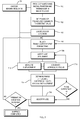
- FIG. 2 illustrates in block-diagram form an exemplary system for performing transducer mapping in accordance with various embodiments hereof, and the interplay between the different system components.
- the system includes, first, the focused ultrasound transducer hardware 202, which itself includes the transducer array, a frequency generator for providing an electronic drive signal, and drivers for the transducer elements.
- the term "transducer” refers to the entire array, as distinguished from the individual transducer elements.
- Each driver contains electronic circuitry for setting the phase of the respective transducer element(s), and optionally also for adjusting the amplitude(s) of vibrations.
- each transducer elements is independently controllable by a separate associated driver.
- driver elements are organized (e.g., via hardwiring or configurable switches) into multiple groups of elements driven collectively by the same driver.
- the drivers are controlled by a control station 204, which may include a computer system specially designed for use with the transducer hardware, or a general-purpose computer (or cluster of computers) having suitable (and conventional) driver software installed.
- the mapping system 200 further includes MRI (or other tomographic or imaging) hardware 206, i.e., an MRI apparatus and related driver components, which is likewise controlled by the control station 204.
- control functionality for the MRI hardware 206 may be implemented in a special-purpose computer system, or in conventional driver software installed on a general-purpose computer system.
- the transducer hardware 202 and MRI hardware 206 may be controlled by the same computer within control station 204, or by separate computers that are in communication with one another.
- computational functionality for processing and analyzing the images acquired with the MRI hardware 206 may be integrated with the MRI apparatus, or implemented (e.g., as a separate software module) in control station 204.
- the control station 204 sends control signals to the ultrasound transducer hardware 202 to vary one or more parameters affecting the focus properties. For example, the control station 204 may cause a phase modulation of a particular transducer element or group of elements. Further, the control station 204 provides scan parameters, or other signals triggering and/or controlling image acquisition, to the MRI or other imaging hardware 206. The relative timing of the ultrasound generation and/or modulation with respect to image acquisition may be specified in an imaging sequence, which may be programmed into the control station 204. The control station 204 may then send trigger signals to the ultrasound transducer hardware 202 and the MRI hardware 206, ensuring correct timing between the signals in accordance with the imaging sequence. Alternatively, the control station 204 may communicate a time-delay parameter, which specifies the time delay between the RF pulses and ultrasound pulses, to the MRI hardware 206, which sends a corresponding trigger pulse directly to the ultrasound transducer hardware 204.
- a time-delay parameter which specifies the time delay between the RF pulse
- the acquired images are processed to determine one or more parameter(s) indicative of the focus quality, which are used in the control station 204 for subsequent mapping steps.
- a material displacement indicative of the intensity in the focus is computationally extracted from the images, and the transducer is iteratively adjusted so as to increase the material displacement.
- the mapping process involves maximizing the temperature, and thus intensity, in the focus.
- any imaging technique that provides images suitable for determining focus quality may be used.
- the "quality" of the focus may be expressed by different parameters.
- the focus quality may be measured in terms of a peak intensity or total power delivered (corresponding to an integrated intensity over the focus cross section). If the target area is small, the focus size may be relevant (a smaller focus area generally corresponding to higher focus quality). In some applications (e.g., tissue heating for palliative purposes), homogeneity of the intensity focus area may be important, and focus quality may, accordingly, be measured, at least in part, by the "smoothness" of an intensity profile through the focus.
- FIG. 3 schematically illustrates an experimental setup for mapping an ultrasound transducer using tissue displacement as an indicator of focus quality.
- the transducer 300 is driven so as to focus an ultrasound wave pulse into a phantom 302, which comprises or consists of a material that responds to acoustic pressure in a detectable manner.
- the ultrasound wave exerts acoustic radiation pressure onto the phantom material along its path.
- this pressure is highest, resulting in a temporary local displacement of the material in the longitudinal direction and/or in shear waves that propagate radially away from the focus.
- Suitable phantom materials have high tensile strength (e.g., higher than 100kPa) and small elastic moduli (e.g., Young's modulus less than 1MPa), and may include or consist of jelly-like materials such as, e.g., Silicone Gel RTV6166, provided by General Electric Co., Waterford, NY.
- the material displacement may be visualized in an imaging plane 306 using an imaging techniques such as, e.g., magnetic-resonance-based acoustic radiation force imaging (MR-ARFI).
- MR-ARFI magnetic-resonance-based acoustic radiation force imaging
- the object to be imaged here, the phantom
- a relatively uniform static magnetic field having a field strength of, typically, between about 1.5 and about 3.0 Tesla.
- Such a field may be generated, for example, by a large cylindrical electromagnet coil 308.
- the static magnetic field causes hydrogen nuclei spins to align and precess about the general direction of the magnetic field.
- Radio frequency (RF) pulses and magnetic gradients are then superimposed on the static magnetic field to cause some of the aligned spins to alternate between a temporary high-energy non-aligned state and the aligned state, thereby inducing an RF response signal, called the MR echo or MR response signal, in the RF antenna 310.
- RF Radio frequency
- transient-motion or displacement-sensitizing magnetic field gradients are applied to the phantom by gradient coils, which are part of standard MRI systems and are typically located near the cylindrical electromagnet coil 308.
- the ultrasound pulse is applied in the presence of such gradients, the resulting displacement is directly encoded into the phase of the MR response signal.
- the gradient coils and transducer may be configured such that the ultrasound pulse pushes phantom material near the focus towards regions of the magnetic field with higher field strengths.
- the phase of the MR response signal changes proportionally, thereby encoding in the signal the displacement caused by the ultrasound radiation pressure.
- FIGS. 4A-4C illustrate five exemplary MR-ARFI sequences that may be used in embodiments of the invention. These sequence diagrams illustrate the order in which the displacement-encoding magnetic field gradients (thin solid lines), ultrasound pulses (dotted lines), and RF pulses (thick solid lines) appear in time. Three different field gradient sets are shown: two single lobes (a), repeated bipolars (b), and inverted bipolars (c). For gradient set (a), ultrasound may be applied during either the first or the second lobe.
- ultrasound may be applied during the first or the second halves of the bipolars.
- MR-ARFI sequences utilize magnetic field gradients that are synchronized with the ultrasound pulses.
- a sequence like the repeated bipolar sequence (b) shown in FIGS. 4A-4C may be used.
- FIG. 5 An example of an MR-ARFI image of an ultrasound focus region is shown in FIG. 5 .
- the material displacement with respect to an equilibrium position varies between about -1 ⁇ m and 5 ⁇ m. as indicated in the color-coding of the image.
- the acoustic field intensity is maximized when the elements of the ultrasound transducer emit acoustic waves that are all in phase at the focus position. If a transducer element is out of phase with respect to the others, the focus intensity in the center decreases. This relationship can be exploited to optimize the focus, and thus to map and adjust the transducer elements.
- the correct phase of the last element can be determined by tuning the phase over a full cycle (e.g., between - ⁇ and + ⁇ ), measuring for each phase the displacement in the focus center, and then setting the phase to the value corresponding to the maximum displacement.
- FIG. 6 depicts the results of such an adjustment procedure.
- the material displacement over the full phase cycle of one element varies between about 4.85 ⁇ m and about 5.4 ⁇ m.
- the maximum displacement occurs at about 0.12 rad. Consequently, the focus intensity and quality can be improved by introducing a phase shift of 0.12 rad for the tested transducer element.
- mapping of the full transducer array is accomplished by varying and adjusting the phase (and/or amplitude) of each element, one at a time, while driving the remaining elements at constant phase.
- the focus quality has significantly improved. Since the necessary phase adjustments of the transducer elements are all interrelated, however, the focus may not yet be optimal after one iteration. Therefore, in some embodiments, the procedure may be repeated iteratively. With each iteration, the phase adjustments made to maximize the displacement in the focus will, generally, decrease.
- a termination condition may be defined by setting a threshold value for phase adjustments, below which further adjustments are deemed immaterial or not clinically necessary.
- the number of iterations required to reach the termination condition may depend on the order in which the transducer elements are mapped.
- a mathematical algorithm for example a "greedy algorithm" as known to persons of skill in the art, may be used to select a mapping order that results in fast convergence of the phase settings.
- the transducer elements may be grouped, and groups of elements may be mapped simultaneously.
- FIG. 7 illustrates a representative method for mapping an ultrasound transducer array in accordance with various embodiments of the invention.
- the method involves, in a first step 700, providing a phantom, and installing the transducer array and phantom in an MRI apparatus. Further, an imaging sequence defining the duration and relative times of ultrasound pulses, RF pulses, and encoding gradients is chosen (step 701). The phases of the transducer elements are then set to a constant value (step 702), and the focus location is determined by identifying the position of the phantom's maximal displacement in the MR-ARFI image (step 703). An iterative phase-adjustment process is subsequently started by selecting one element (or one group of elements) for mapping (step 704).
- the selected element is driven at a variable phase (step 708), and for each phase setting, the transducer elements are collectively driven to generate an ultrasound focus in the phantom (710).
- the displacement of phantom material in the focus region is measured by MR-ARFI in accordance with the imaging sequence (step 712).
- this step is repeated until the variable phase of the selected transducer element has covered a range of phases spanning an interval of 2 ⁇ .
- the phase difference between the constant phase and the phase of the selected transducer element that maximizes the displacement is determined (step 712).
- step 718 the phase of the transducer element is adjusted by this difference. Steps 704 through 718 are then repeated until each transducer element has been mapped. If the phase adjustments made in step 718 fall below a pre-determined threshold value, or an alternative termination condition is satisfied, the mapping is complete. Otherwise, the mapping procedure for the array may be repeated, starting with the adjusted phase settings of the transducer elements.
- phase differences may first be determined for all the elements, without adjustments being made, and following this mapping procedure, all the phase adjustments may be made at once.
- an iterative phase adjustment is not needed because the reference phase, i.e., the phase of the transducer as a whole, disregarding the element under mapping, is nearly the same for all elements.
- the phases of the transducer elements may be adjusted simultaneously, rather than in succession, by varying a drive parameter affecting some or all of the elements.
- the relative phases between transducer elements may be expressed in terms of a functional dependence of the phase on the position of a transducer element along one or two axes of the transducer array, and such functional dependence, in turn, may be characterized by one or few mathematical parameters (e.g., a linear phase gradient and/or coefficients of higher-order components of the phase modulation in one- or two-dimensional space).
- the coefficients in the functional dependence may be varied, and the corresponding effect on the focus quality observed.
- amplitude variations of individual elements or groups of elements may also be employed to improve the focus quality.
- the transducer elements may be movable with respect to the one another within certain ranges (e.g., as a consequence of being mounted on electronically controllable microtranslator stages, pivots, etc.).
- the experimental adjustment procedure described above may then be used to fine-tune the positions and/or orientations of the transducer elements.
- the overall shape, position, and orientation of the transducer may likewise be controllable, e.g., via clasps, movable bearings, etc.
Description
- The present application claims priority to and the benefit of
U.S. Provisional Patent Application No. 61/251,450, filed on October 14, 2009 - The present invention relates, generally, to methods for mapping ultrasound transducers. In particular, various embodiments are directed to improving the quality of the ultrasound focus using experimental feedback.
- Focused ultrasound (i.e., acoustic waves having a frequency greater than about 20 kilohertz) can be used to image or therapeutically treat internal body tissues within a patient. For example, ultrasonic waves may be used to ablate tumors, eliminating the need for the patient to undergo invasive surgery. For this purpose, a piezo-ceramic transducer is placed externally to the patient, but in close proximity to the tissue to be ablated ("the target"). The transducer converts an electronic drive signal into mechanical vibrations, resulting in the emission of acoustic waves. The transducer may be shaped so that the waves converge in a focal zone. Alternatively or additionally, the transducer may be formed of a plurality of individually driven transducer elements whose phases can each be controlled independently from one another. Such a "phased-array" transducer facilitates steering the focal zone to different locations by adjusting the relative phases between the transducers. Magnetic resonance imaging (MRI) may be used to visualize the patient and target, and thereby to guide the ultrasound beam
WO 0244753 - The effectiveness of ultrasound therapy depends on the accuracy of the focus location, the sharpness and shape of the focal zone, and the avoidance of "hot spots" (i.e., regions of high ultrasound intensity) outside the target. Transducer elements that are not properly configured or controlled can lead to improper focus location and reduced focus quality, resulting in less effective therapy, and possibly damage to healthy tissue surrounding the target. It is therefore desirable to correct any mechanical misconfigurations. Improper transducer configuration may result from manufacturing errors, inadvertent shifting of transducer elements from their expected locations during use or repair, deformation of the transducer due to thermal expansion, or a combination of these and other effects. Even slight locational deviations can have significant effects on the quality of the transducer output. For example, as illustrated in
FIG. 1 , if the height of a curved transducer surface having a width of 120 mm and a nominal radius of curvature of 160 mm changes by only 1 mm, the ultrasound focus shifts by about 13 mm. In a phased array, deviations of the transducer locations from the intended locations can be compensated for by adjusting the phases with which the elements are driven. This procedure is hereinafter referred to as "mapping" the transducer. - One approach to mapping a phased-array transducer surface involves driving each transducer element individually to produce an acoustic wave pulse in water; measuring the arrival of the acoustic wave pulse in three locations using a hydrophone: determining for each location the time of flight, and thus the distance, from the transducer element; and calculating the coordinates of the element location by triangulation from the three measurements. Based on the intended and the measured actual locations of the transducer elements, the necessary phase adjustments can be calculated. This method is described in
U.S. Patent No. 7,535,794 to Prus et al. In addition to a hydrophone, implementation of the method requires other auxiliary equipment, such as an amplifier and data-acquisition module. Further, to avoid damaging the hydrophone, the mapping is typically performed at transducer power levels significantly below those used during normal operation, which can undermine the validity of the adjustments under therapeutic conditions. Alternative transducer mapping methods that do not have these drawbacks are therefore desirable. - The present invention generally provides methods for mapping a phased-array transducer by generating an ultrasound focus and improving the focus quality based on experimental feedback. In various embodiments, one or more focus-affecting parameters (such as the phase and/or amplitude of one or more transducer elements) are varied, and the resulting variation of the focus quality is measured (e.g., in terms of an integral or peak intensity, focus size, or intensity profile). The focus-affecting parameter(s) are then set to values for which the focus quality is optimized. For example, the relative phases of the transducer elements may be fine-tuned one at a time to maximize the intensity at the focus. In this manner, unwanted phase shifts resulting from electronic delays or other sources may be corrected, and any deviations from the intended locations of the transducer elements may be compensated for without the need to explicitly determine the actual transducer locations.
- During the mapping procedure, the ultrasound focus may be generated in a phantom. To determine the focus quality, the focus is visualized, by magnetic-resonance acoustic radiation force imaging (MR-ARFI) - an MRI technique measuring minute material displacements that are caused by and indicative of the acoustic field. The displacement increases with the acoustic field intensity. Thus, by adjusting the transducer element phases (and/or amplitudes or other focus-affecting parameters) so as to increase the material displacement in the phantom, the intensity at the focus and, consequently, the focus quality may be improved. Advantageously, MR-ARFI facilitates mapping the transducer at normal operational power levels, which increases the relevance and applicability of any mapping-based adjustments to the subsequent therapeutic operation. Further, the ultrasound focus may be imaged during the mapping procedure with the same MRI or other imaging apparatus (e.g., X-ray-based computer-aided tomography or other tomographic modality) that is used to guide the focus during therapeutic operation, and, consequently, additional (auxiliary) mapping equipment is not needed.
- In one aspect, it is provided a method for improving and/or optimizing the focus of an ultrasound transducer having a plurality of transducer elements. The method includes driving the plurality of transducer elements so as to generate an ultrasound focus, varying a focus-affecting parameter associated with one or more of the transducer elements, measuring a resulting variation on the quality of the focus, and selecting parameter value(s) that result in the best focus quality. The focus-varying parameter(s) may be or include the phase and/or amplitude of one of the transducer elements (or a group of jointly driven elements), or a phase/amplitude gradient or other parameter determining relative phase/amplitude settings of multiple transducer elements that form the whole transducer or a region thereof, or a combination of such parameters. In embodiments in which the location and/or orientation of the transducer or transducer elements are susceptible to direct user control, the focus-varying parameter(s) may, alternatively or additionally, include such location(s) and/or orientation(s). Other focus-varying parameters include, e.g., the drive frequency of the transducer. The quality measurement may involve, for instance, scanning a profile of the focus (e.g., measuring the intensity in the focus region along a line through the focus), measuring the peak (i.e., maximum) intensity of the focus, and/or measuring the integral intensity or size of the focus (i.e., integrating the intensity or area over the cross-section of the focus, where the cross-section is defined, e.g., by the regions in which the intensity is more than a set fraction, e.g., half or 1/e, of the peak intensity).
- In certain embodiments, varying the focus-varying parameter(s) and measuring the resultant focus quality includes driving a selected one of the transducer elements at a variable phase while driving the other transducer elements at a constant phase (thereby varying the focus quality); determining the phase difference, if any, between the constant and variable phases where the focus quality is optimized: and, if the phase difference is non-zero, adjusting the relative phase of the selected transducer element based thereon. These steps may be repeated for the remaining transducer elements.
- In some examples, the quality measurement comprises measuring the displacement associated with the focus using, e.g., ARFI. The ARFI measurement may involve applying a sequence of MR field gradients (such as, e.g., repeated bipolar gradients). The ultrasound focus may generated by an ultrasound pulse synchronized with the sequence of MR field gradients. The method may further involve providing a phantom (which may include a material having low tensile strength and/or a small elastic modulus), and generating the ultrasound focus and measuring the focus quality in the phantom.
- The invention is directed according to
claim 1 to a method for mapping an ultrasound transducer comprising a plurality of transducer elements. The method includes driving the transducer elements so as to generate an ultrasound focus, and measuring a displacement associated with the focus by ARFI. Further, it involves varying the displacement by driving one of the transducer elements at a variable phase while driving the other transducer elements at a constant phase, and determining the phase difference, if any, between the constant and variable phases at which the displacement is maximized. If the phase difference is non-zero, the relative phase of the selected transducer element is adjusted based on the phase difference. The phase difference may also be used to determine the location of the selected transducer element. The application of a variable phase and determination of the phase difference between the variable and constant phases may be repeated for the remaining transducer elements. The ultrasound focus may be generated, and the displacement be measured, in a phantom, which may have a low tensile strength and/or a small elastic modulus. Acoustic-radiation force imaging to measure the displacement may involve applying a sequence of MR field gradients, e.g., a sequence including repeated bipolar gradients. The transducer elements may be driven so as to generate an ultrasound pulse synchronized with the sequence of MR field gradients. - The above-described mapping method(s) may be varied by grouping transducer elements and mapping a group, rather than an individual element, at a time according to
claim 2. Accordingly, in yet another aspect of the invention, a selected group of transducer elements is driven at a variable phase while other groups of transducer elements are driven at a constant phase, and the phase difference between the constant and variable phases that maximizes the displacement associated with the focus may be determined and form the basis for adjusting the relative phase of the selected group of transducer elements. - In a further aspect, the invention is directed to a method for controlling an ultrasound transducer having a plurality of transducer elements. The method includes mapping the ultrasound transducer as described above by driving the transducers to generate an ultrasound focus; varying a focus-affecting parameter associated with at least one of the elements and measuring a resulting variation on a quality of the focus; and selecting a value of the parameter associated with a best focus quality. In particular, in some embodiments, mapping may include measuring a displacement associated with the focus (e.g., using ARFI), and determining, for each of the transducer elements, the relative phase associated with that element by driving the transducer element at a variable phase while driving the other transducer elements at a constant phase and determining the phase difference between the constant and variable phases that maximizes the displacement. The method further includes controlling the transducer based on the mapping step (e.g., by adjusting the relative phase of each transducer for which the phase difference is non-zero). Controlling the transducer may include driving the elements to produce outputs converging at a focus corresponding to a target treatment region. Mapping may be carried out using a phantom, and may be repeated in between therapeutic applications of ultrasound.
- The foregoing will be more readily understood from the following detailed description of the invention in conjunction with the drawings, wherein:
-
FIG. 1 is a schematic drawing illustrating the effect of a change in the transducer surface on the focus location; -
FIG. 2 is a block-diagram illustrating, on a high level, a system for performing transducer mapping in accordance with some embodiments of the invention; -
FIG. 3 a schematic diagram illustrating, in more detail, the configuration of a transducer mapping system in accordance with some embodiments; -
FIGS. 4A-4C illustrate various MR-ARFI sequences in accordance with some embodiments; -
FIG. 5 is an image of material displacements in an ultrasound focus region in accordance with some embodiments; -
FIG. 6 is a graph illustrating material displacement in the focus center as a function of the phase of an individual transducer element, as it may be used in mapping methods in accordance with various embodiments; and -
FIG. 7 is a flow chart illustrating an approach to mapping an ultrasound transducer array in accordance with various embodiments of the invention. -
FIG. 2 illustrates in block-diagram form an exemplary system for performing transducer mapping in accordance with various embodiments hereof, and the interplay between the different system components. The system includes, first, the focusedultrasound transducer hardware 202, which itself includes the transducer array, a frequency generator for providing an electronic drive signal, and drivers for the transducer elements. (As used herein, the term "transducer" refers to the entire array, as distinguished from the individual transducer elements.) Each driver contains electronic circuitry for setting the phase of the respective transducer element(s), and optionally also for adjusting the amplitude(s) of vibrations. In some embodiments, each transducer elements is independently controllable by a separate associated driver. In alternative embodiments, driver elements are organized (e.g., via hardwiring or configurable switches) into multiple groups of elements driven collectively by the same driver. The drivers are controlled by acontrol station 204, which may include a computer system specially designed for use with the transducer hardware, or a general-purpose computer (or cluster of computers) having suitable (and conventional) driver software installed. - The
mapping system 200 further includes MRI (or other tomographic or imaging)hardware 206, i.e., an MRI apparatus and related driver components, which is likewise controlled by thecontrol station 204. Again, control functionality for theMRI hardware 206 may be implemented in a special-purpose computer system, or in conventional driver software installed on a general-purpose computer system. Thetransducer hardware 202 andMRI hardware 206 may be controlled by the same computer withincontrol station 204, or by separate computers that are in communication with one another. Further, computational functionality for processing and analyzing the images acquired with theMRI hardware 206 may be integrated with the MRI apparatus, or implemented (e.g., as a separate software module) incontrol station 204. - During the mapping procedure, the
control station 204 sends control signals to theultrasound transducer hardware 202 to vary one or more parameters affecting the focus properties. For example, thecontrol station 204 may cause a phase modulation of a particular transducer element or group of elements. Further, thecontrol station 204 provides scan parameters, or other signals triggering and/or controlling image acquisition, to the MRI orother imaging hardware 206. The relative timing of the ultrasound generation and/or modulation with respect to image acquisition may be specified in an imaging sequence, which may be programmed into thecontrol station 204. Thecontrol station 204 may then send trigger signals to theultrasound transducer hardware 202 and theMRI hardware 206, ensuring correct timing between the signals in accordance with the imaging sequence. Alternatively, thecontrol station 204 may communicate a time-delay parameter, which specifies the time delay between the RF pulses and ultrasound pulses, to theMRI hardware 206, which sends a corresponding trigger pulse directly to theultrasound transducer hardware 204. - The acquired images are processed to determine one or more parameter(s) indicative of the focus quality, which are used in the
control station 204 for subsequent mapping steps. For example, in MR-ARFI-based systems, a material displacement indicative of the intensity in the focus is computationally extracted from the images, and the transducer is iteratively adjusted so as to increase the material displacement. Similarly, if thermal MRI is employed, the mapping process involves maximizing the temperature, and thus intensity, in the focus. In general, any imaging technique that provides images suitable for determining focus quality may be used. Depending on the contemplated ultrasound application, the "quality" of the focus may be expressed by different parameters. For therapeutic applications involving targeted tissue destruction, for example, the focus quality may be measured in terms of a peak intensity or total power delivered (corresponding to an integrated intensity over the focus cross section). If the target area is small, the focus size may be relevant (a smaller focus area generally corresponding to higher focus quality). In some applications (e.g., tissue heating for palliative purposes), homogeneity of the intensity focus area may be important, and focus quality may, accordingly, be measured, at least in part, by the "smoothness" of an intensity profile through the focus. -
FIG. 3 schematically illustrates an experimental setup for mapping an ultrasound transducer using tissue displacement as an indicator of focus quality. During the mapping procedure, thetransducer 300 is driven so as to focus an ultrasound wave pulse into aphantom 302, which comprises or consists of a material that responds to acoustic pressure in a detectable manner. The ultrasound wave exerts acoustic radiation pressure onto the phantom material along its path. At thefocus 304, where waves from the individual transducer elements converge, this pressure is highest, resulting in a temporary local displacement of the material in the longitudinal direction and/or in shear waves that propagate radially away from the focus. By using a soft phantom that responds to acoustic pressure with large enough shear strain (e.g., with a shear strain of at least 10-2), a detectable displacement field that directly reflects the acoustic field may be obtained. Suitable phantom materials have high tensile strength (e.g., higher than 100kPa) and small elastic moduli (e.g., Young's modulus less than 1MPa), and may include or consist of jelly-like materials such as, e.g., Silicone Gel RTV6166, provided by General Electric Co., Waterford, NY. - The material displacement may be visualized in an
imaging plane 306 using an imaging techniques such as, e.g., magnetic-resonance-based acoustic radiation force imaging (MR-ARFI). In MR-based imaging methods, the object to be imaged (here, the phantom) is placed in a relatively uniform static magnetic field having a field strength of, typically, between about 1.5 and about 3.0 Tesla. Such a field may be generated, for example, by a largecylindrical electromagnet coil 308. The static magnetic field causes hydrogen nuclei spins to align and precess about the general direction of the magnetic field. Radio frequency (RF) pulses and magnetic gradients are then superimposed on the static magnetic field to cause some of the aligned spins to alternate between a temporary high-energy non-aligned state and the aligned state, thereby inducing an RF response signal, called the MR echo or MR response signal, in theRF antenna 310. - In MR-ARFI, transient-motion or displacement-sensitizing magnetic field gradients are applied to the phantom by gradient coils, which are part of standard MRI systems and are typically located near the
cylindrical electromagnet coil 308. When the ultrasound pulse is applied in the presence of such gradients, the resulting displacement is directly encoded into the phase of the MR response signal. For example, the gradient coils and transducer may be configured such that the ultrasound pulse pushes phantom material near the focus towards regions of the magnetic field with higher field strengths. In response to the resulting change in the magnetic field, the phase of the MR response signal changes proportionally, thereby encoding in the signal the displacement caused by the ultrasound radiation pressure. - To achieve high image contrast, the ultrasound pulse, encoding gradients, and RF pulse are precisely timed with respect to each other according to a suitable displacement-encoding sequence.
FIGS. 4A-4C illustrate five exemplary MR-ARFI sequences that may be used in embodiments of the invention. These sequence diagrams illustrate the order in which the displacement-encoding magnetic field gradients (thin solid lines), ultrasound pulses (dotted lines), and RF pulses (thick solid lines) appear in time. Three different field gradient sets are shown: two single lobes (a), repeated bipolars (b), and inverted bipolars (c). For gradient set (a), ultrasound may be applied during either the first or the second lobe. Similarly, for gradient set (c), ultrasound may be applied during the first or the second halves of the bipolars. In general, MR-ARFI sequences utilize magnetic field gradients that are synchronized with the ultrasound pulses. In preferred embodiments, a sequence like the repeated bipolar sequence (b) shown inFIGS. 4A-4C may be used. - An example of an MR-ARFI image of an ultrasound focus region is shown in
FIG. 5 . As shown, the material displacement with respect to an equilibrium position varies between about -1 □m and 5 □m. as indicated in the color-coding of the image. In general, the stronger the acoustic field intensity, the greater will be the maximum displacement at the center of the focus. The acoustic field intensity, in turn, is maximized when the elements of the ultrasound transducer emit acoustic waves that are all in phase at the focus position. If a transducer element is out of phase with respect to the others, the focus intensity in the center decreases. This relationship can be exploited to optimize the focus, and thus to map and adjust the transducer elements. Assuming, for example, that all but one of the transducer elements are properly configured, the correct phase of the last element can be determined by tuning the phase over a full cycle (e.g., between -□ and +□), measuring for each phase the displacement in the focus center, and then setting the phase to the value corresponding to the maximum displacement.FIG. 6 depicts the results of such an adjustment procedure. In the illustrated example, the material displacement over the full phase cycle of one element varies between about 4.85 □m and about 5.4 □m. The maximum displacement occurs at about 0.12 rad. Consequently, the focus intensity and quality can be improved by introducing a phase shift of 0.12 rad for the tested transducer element. - In certain embodiments, mapping of the full transducer array is accomplished by varying and adjusting the phase (and/or amplitude) of each element, one at a time, while driving the remaining elements at constant phase. Typically, after each element has been mapped independently, the focus quality has significantly improved. Since the necessary phase adjustments of the transducer elements are all interrelated, however, the focus may not yet be optimal after one iteration. Therefore, in some embodiments, the procedure may be repeated iteratively. With each iteration, the phase adjustments made to maximize the displacement in the focus will, generally, decrease. Thus, a termination condition may be defined by setting a threshold value for phase adjustments, below which further adjustments are deemed immaterial or not clinically necessary. The number of iterations required to reach the termination condition may depend on the order in which the transducer elements are mapped. A mathematical algorithm, for example a "greedy algorithm" as known to persons of skill in the art, may be used to select a mapping order that results in fast convergence of the phase settings. In certain alternative embodiments, the transducer elements may be grouped, and groups of elements may be mapped simultaneously.
-
FIG. 7 illustrates a representative method for mapping an ultrasound transducer array in accordance with various embodiments of the invention. The method involves, in afirst step 700, providing a phantom, and installing the transducer array and phantom in an MRI apparatus. Further, an imaging sequence defining the duration and relative times of ultrasound pulses, RF pulses, and encoding gradients is chosen (step 701). The phases of the transducer elements are then set to a constant value (step 702), and the focus location is determined by identifying the position of the phantom's maximal displacement in the MR-ARFI image (step 703). An iterative phase-adjustment process is subsequently started by selecting one element (or one group of elements) for mapping (step 704). The selected element is driven at a variable phase (step 708), and for each phase setting, the transducer elements are collectively driven to generate an ultrasound focus in the phantom (710). Substantially simultaneously, or after a time interval overlapping with the generation of the ultrasound focus, the displacement of phantom material in the focus region is measured by MR-ARFI in accordance with the imaging sequence (step 712). Typically, this step is repeated until the variable phase of the selected transducer element has covered a range of phases spanning an interval of 2□. Instep 714, the phase difference between the constant phase and the phase of the selected transducer element that maximizes the displacement is determined (step 712). If the phase difference is non-zero, the phase of the transducer element is adjusted by this difference (step 718).Steps 704 through 718 are then repeated until each transducer element has been mapped. If the phase adjustments made instep 718 fall below a pre-determined threshold value, or an alternative termination condition is satisfied, the mapping is complete. Otherwise, the mapping procedure for the array may be repeated, starting with the adjusted phase settings of the transducer elements. - The method described above may be varied in several ways. For example, the phase differences may first be determined for all the elements, without adjustments being made, and following this mapping procedure, all the phase adjustments may be made at once. In this case, an iterative phase adjustment is not needed because the reference phase, i.e., the phase of the transducer as a whole, disregarding the element under mapping, is nearly the same for all elements. Further, in some embodiments, the phases of the transducer elements may be adjusted simultaneously, rather than in succession, by varying a drive parameter affecting some or all of the elements. For example, the relative phases between transducer elements may be expressed in terms of a functional dependence of the phase on the position of a transducer element along one or two axes of the transducer array, and such functional dependence, in turn, may be characterized by one or few mathematical parameters (e.g., a linear phase gradient and/or coefficients of higher-order components of the phase modulation in one- or two-dimensional space). Rather than modulating the phase of an individual element, then, the coefficients in the functional dependence may be varied, and the corresponding effect on the focus quality observed.
- Alternatively or in addition to phase variations, amplitude variations of individual elements or groups of elements (including variations of the functional dependence of the amplitude on a position along the array) may also be employed to improve the focus quality. Further, in some embodiments, the transducer elements may be movable with respect to the one another within certain ranges (e.g., as a consequence of being mounted on electronically controllable microtranslator stages, pivots, etc.). The experimental adjustment procedure described above may then be used to fine-tune the positions and/or orientations of the transducer elements. The overall shape, position, and orientation of the transducer may likewise be controllable, e.g., via clasps, movable bearings, etc.
- Although the present invention has been described with reference to specific details, it is not intended that such details should be regarded as limitations upon the scope of the invention, except as and to the extent that they are included in the accompanying claims.
Claims (8)
- A method for mapping an ultrasound transducer comprising a plurality of transducer elements, the method comprising:(a) driving the plurality of transducer elements so as to generate an ultrasound focus;(b) measuring a displacement associated with the focus by using magnetic resonance acoustic radiation force imaging;(c) driving a selected one of the transducer elements at a variable phase while driving the other transducer elements at a constant phase, thereby varying the displacement;(d) determining a phase difference, if any, between the constant and variable phases where the displacement is maximized; and(e) if the phase difference is non-zero, adjusting a relative phase of the selected transducer element based thereon.
- A method for mapping an ultrasound transducer comprising a plurality of transducer elements, the method comprising:(a) driving the plurality of transducer elements so as to generate an ultrasound focus;(b) measuring a displacement associated with the focus using magnetic resonance acoustic radiation force imaging;(c) grouping the transducer elements;(d) driving a selected group of transducer elements at a variable phase while driving the other groups of transducer elements at a constant phase, thereby varying the displacement;(e) determining a phase difference, if any, between the constant and variable phases where the displacement is maximized; and(f) if the phase difference is non-zero, adjusting a relative phase of the selected group of transducer elements based thereon.
- The method of claim 1 or claim 2, wherein the magnetic resonance acoustic- radiation force imaging to measure the displacement comprises applying a sequence of MR field gradients.
- The method of claim 3, wherein the sequence of MR field gradients comprises repeated bipolar gradients.
- The method of claim 3, wherein the transducer elements are driven so as to generate an ultrasound pulse synchronized with the sequence of MR field gradients.
- The method of claim 1 or claim 2, wherein the ultrasound focus is generated and the displacement is measured in a phantom.
- The method of claim 6, wherein the phantom has a low tensile strength.
- The method of claim 6 or claim 7, wherein the phantom has a small elastic modulus.
Applications Claiming Priority (2)
| Application Number | Priority Date | Filing Date | Title |
|---|---|---|---|
| US25145009P | 2009-10-14 | 2009-10-14 | |
| PCT/IB2010/002757 WO2011045669A2 (en) | 2009-10-14 | 2010-10-14 | Mapping ultrasound transducers |
Publications (2)
| Publication Number | Publication Date |
|---|---|
| EP2489034A2 EP2489034A2 (en) | 2012-08-22 |
| EP2489034B1 true EP2489034B1 (en) | 2016-11-30 |
Family
ID=43828301
Family Applications (1)
| Application Number | Title | Priority Date | Filing Date |
|---|---|---|---|
| EP10785194.1A Active EP2489034B1 (en) | 2009-10-14 | 2010-10-14 | Mapping ultrasound transducers |
Country Status (3)
| Country | Link |
|---|---|
| US (2) | US8661873B2 (en) |
| EP (1) | EP2489034B1 (en) |
| WO (1) | WO2011045669A2 (en) |
Families Citing this family (29)
| Publication number | Priority date | Publication date | Assignee | Title |
|---|---|---|---|---|
| US8256430B2 (en) | 2001-06-15 | 2012-09-04 | Monteris Medical, Inc. | Hyperthermia treatment and probe therefor |
| US8409099B2 (en) * | 2004-08-26 | 2013-04-02 | Insightec Ltd. | Focused ultrasound system for surrounding a body tissue mass and treatment method |
| EP1960993B1 (en) * | 2005-11-23 | 2016-11-02 | Insightec-Image Guided Treatment, Ltd. | Hierarchical switching in ultra-high density ultrasound array |
| US20100030076A1 (en) * | 2006-08-01 | 2010-02-04 | Kobi Vortman | Systems and Methods for Simultaneously Treating Multiple Target Sites |
| EP2174007A4 (en) * | 2007-07-02 | 2017-05-10 | Borgwarner Inc. | Inlet design for a pump assembly |
| US8425424B2 (en) * | 2008-11-19 | 2013-04-23 | Inightee Ltd. | Closed-loop clot lysis |
| EP2440292A1 (en) * | 2009-06-10 | 2012-04-18 | Insightec Ltd. | Acoustic-feedback power control during focused ultrasound delivery |
| WO2011024074A2 (en) | 2009-08-26 | 2011-03-03 | Insightec Ltd. | Asymmetric phased-array ultrasound transducer |
| EP2489034B1 (en) | 2009-10-14 | 2016-11-30 | Insightec Ltd. | Mapping ultrasound transducers |
| US9852727B2 (en) | 2010-04-28 | 2017-12-26 | Insightec, Ltd. | Multi-segment ultrasound transducers |
| US8932237B2 (en) | 2010-04-28 | 2015-01-13 | Insightec, Ltd. | Efficient ultrasound focusing |
| CN104602638B (en) | 2012-06-27 | 2017-12-19 | 曼特瑞斯医药有限责任公司 | System for influenceing to treat tissue |
| US10512794B2 (en) | 2016-12-16 | 2019-12-24 | Brainsonix Corporation | Stereotactic frame |
| US9061133B2 (en) | 2012-12-27 | 2015-06-23 | Brainsonix Corporation | Focused ultrasonic transducer navigation system |
| US10974078B2 (en) | 2012-12-27 | 2021-04-13 | Brainsonix Corporation | Treating degenerative dementia with low intensity focused ultrasound pulsation (LIFUP) device |
| JP6442788B2 (en) * | 2013-03-06 | 2018-12-26 | インサイテック・リミテッド | Frequency optimization in ultrasonic treatment |
| WO2014170144A1 (en) * | 2013-04-05 | 2014-10-23 | Koninklijke Philips N.V. | Energy deposition zone determination for a catheter with an ultrasound array |
| KR20140132811A (en) * | 2013-05-06 | 2014-11-19 | 삼성전자주식회사 | Ultrasound imaging apparatus and control method for the same |
| WO2015143025A1 (en) | 2014-03-18 | 2015-09-24 | Monteris Medical Corporation | Image-guided therapy of a tissue |
| US20150265353A1 (en) | 2014-03-18 | 2015-09-24 | Monteris Medical Corporation | Image-guided therapy of a tissue |
| US10675113B2 (en) | 2014-03-18 | 2020-06-09 | Monteris Medical Corporation | Automated therapy of a three-dimensional tissue region |
| KR102367251B1 (en) * | 2015-02-02 | 2022-02-25 | 삼성디스플레이 주식회사 | Display device |
| US11156686B2 (en) * | 2015-03-04 | 2021-10-26 | Koninklijke Philips N.V. | Acoustic radiation force imaging |
| US10327830B2 (en) | 2015-04-01 | 2019-06-25 | Monteris Medical Corporation | Cryotherapy, thermal therapy, temperature modulation therapy, and probe apparatus therefor |
| US10230271B2 (en) | 2016-03-03 | 2019-03-12 | uBeam Inc. | Beamforming for wireless power transfer |
| US10148137B2 (en) | 2016-03-03 | 2018-12-04 | uBeam Inc. | Beamforming for wireless power transfer |
| WO2018020315A1 (en) * | 2016-07-25 | 2018-02-01 | Insightec, Ltd. | Ultrasound autofocusing using reflections |
| US10715242B1 (en) * | 2019-09-25 | 2020-07-14 | Facebook, Inc. | Grouping antenna elements to enhanced an antenna array response resolution |
| US11759661B2 (en) | 2020-05-20 | 2023-09-19 | Brainsonix Corporation | Ultrasonic transducer treatment device |
Family Cites Families (355)
| Publication number | Priority date | Publication date | Assignee | Title |
|---|---|---|---|---|
| US1006603A (en) | 1910-02-04 | 1911-10-24 | Cement Tile Machinery Company | Former-head for tile-machines. |
| US2795709A (en) | 1953-12-21 | 1957-06-11 | Bendix Aviat Corp | Electroplated ceramic rings |
| US3142035A (en) | 1960-02-04 | 1964-07-21 | Harris Transducer Corp | Ring-shaped transducer |
| DE1766766A1 (en) * | 1968-07-11 | 1971-08-19 | Krupp Gmbh | Device for swiveling a focused, acoustic beam |
| US4000493A (en) | 1971-04-12 | 1976-12-28 | Eastman Kodak Company | Acoustooptic scanner apparatus and method |
| US3974475A (en) | 1971-10-07 | 1976-08-10 | Hoffmann-La Roche Inc. | Method of and apparatus for focusing ultrasonic waves in a focal line |
| US3992693A (en) | 1972-12-04 | 1976-11-16 | The Bendix Corporation | Underwater transducer and projector therefor |
| CA1050654A (en) | 1974-04-25 | 1979-03-13 | Varian Associates | Reconstruction system and method for ultrasonic imaging |
| US3942150A (en) | 1974-08-12 | 1976-03-02 | The United States Of America As Represented By The Secretary Of The Navy | Correction of spatial non-uniformities in sonar, radar, and holographic acoustic imaging systems |
| US4206653A (en) | 1975-10-02 | 1980-06-10 | E M I Limited | Ultrasonic apparatus |
| US4052723A (en) | 1976-04-26 | 1977-10-04 | Westinghouse Electric Corporation | Randomly agglomerated subarrays for phased array radars |
| US4211132A (en) | 1977-11-21 | 1980-07-08 | E. I. Du Pont De Nemours And Company | Apparatus for on-line defect zoning |
| EP0003658A3 (en) | 1978-02-09 | 1979-09-05 | United Kingdom Atomic Energy Authority | Improvements in or relating to an ultrasonic nondestructive testing apparatus |
| AU529113B2 (en) | 1978-04-19 | 1983-05-26 | Commonwealth Of Australia, The | Ultrasonic transducer array |
| CA1137210A (en) | 1979-04-26 | 1982-12-07 | Francis S. Foster | Ultrasonic imaging method and device using one transducer having a line focus aligned with another transducer |
| US4307613A (en) | 1979-06-14 | 1981-12-29 | University Of Connecticut | Electronically focused ultrasonic transmitter |
| DE3069525D1 (en) | 1979-12-17 | 1984-11-29 | Philips Corp | Curved array of sequenced ultrasound transducers |
| DE3119295A1 (en) | 1981-05-14 | 1982-12-16 | Siemens AG, 1000 Berlin und 8000 München | DEVICE FOR DESTROYING CONCRETE IN BODIES |
| EP0068961A3 (en) | 1981-06-26 | 1983-02-02 | Thomson-Csf | Apparatus for the local heating of biological tissue |
| US4441486A (en) | 1981-10-27 | 1984-04-10 | Board Of Trustees Of Leland Stanford Jr. University | Hyperthermia system |
| US4454597A (en) | 1982-05-03 | 1984-06-12 | The United States Of America As Represented By The Secretary Of The Navy | Conformal array compensating beamformer |
| DE3216547C1 (en) | 1982-05-04 | 1983-10-06 | Krautkraemer Gmbh | Method and circuit device for generating and changing a predetermined number of independent DC voltages |
| DE3224453A1 (en) | 1982-06-30 | 1984-01-05 | Siemens AG, 1000 Berlin und 8000 München | ULTRASONIC TOMOGRAPHER |
| US4554925A (en) | 1982-07-07 | 1985-11-26 | Picker International, Ltd. | Nuclear magnetic resonance imaging method |
| DE3374522D1 (en) | 1982-10-26 | 1987-12-23 | University Of Aberdeen | |
| DE3319871A1 (en) | 1983-06-01 | 1984-12-06 | Richard Wolf Gmbh, 7134 Knittlingen | PIEZOELECTRIC CONVERTER FOR DESTROYING CONCRETE IN THE BODY |
| US4505156A (en) | 1983-06-21 | 1985-03-19 | Sound Products Company L.P. | Method and apparatus for switching multi-element transducer arrays |
| US4537074A (en) | 1983-09-12 | 1985-08-27 | Technicare Corporation | Annular array ultrasonic transducers |
| DE3582599D1 (en) | 1984-01-26 | 1991-05-29 | Schlumberger Ltd | QUANTITATIVE DETERMINATION OF UNDERGROUND FORMATION PROPERTIES BY MEASURING ELEMENTS. |
| US4549533A (en) | 1984-01-30 | 1985-10-29 | University Of Illinois | Apparatus and method for generating and directing ultrasound |
| US4616231A (en) | 1984-03-26 | 1986-10-07 | Hughes Aircraft Company | Narrow-band beam steering system |
| JPS6162369A (en) | 1984-08-30 | 1986-03-31 | Tokyo Juki Ind Co Ltd | Actuator using piezoelectric element |
| AT381267B (en) | 1984-09-12 | 1986-09-25 | Ver Edelstahlwerke Ag | USE OF AN ALLOY AS A WELDING MATERIAL |
| US4662222A (en) | 1984-12-21 | 1987-05-05 | Johnson Steven A | Apparatus and method for acoustic imaging using inverse scattering techniques |
| JPS61209643A (en) | 1985-03-15 | 1986-09-17 | 株式会社東芝 | Ultrasonic diagnostic and medical treatment apparatus |
| US4865042A (en) | 1985-08-16 | 1989-09-12 | Hitachi, Ltd. | Ultrasonic irradiation system |
| GB8522819D0 (en) | 1985-09-16 | 1985-10-23 | Mccracken W | Control of vibration energisation |
| GB8529446D0 (en) | 1985-11-29 | 1986-01-08 | Univ Aberdeen | Divergent ultrasound arrays |
| EP0256481B1 (en) | 1986-08-20 | 1994-01-12 | Siemens Aktiengesellschaft | Method and equipment for adaptive focussing in a medical ultrasonic imaging apparatus |
| DE3663860D1 (en) | 1986-12-24 | 1989-07-13 | Hewlett Packard Gmbh | Method of and apparatus for adjusting the intensity profile of an ultrasound beam |
| FR2620294B1 (en) | 1987-09-07 | 1990-01-19 | Technomed Int Sa | PIEZOELECTRIC DEVICE WITH REDUCED NEGATIVE WAVES, AND USE THEREOF FOR EXTRA-BODY LITHOTRITIS OR FOR THE DESTRUCTION OF SPECIAL TISSUES |
| DE3732131A1 (en) | 1987-09-24 | 1989-04-06 | Wolf Gmbh Richard | FOCUSING ULTRASONIC transducer |
| US4989143A (en) | 1987-12-11 | 1991-01-29 | General Electric Company | Adaptive coherent energy beam formation using iterative phase conjugation |
| US5143063A (en) | 1988-02-09 | 1992-09-01 | Fellner Donald G | Method of removing adipose tissue from the body |
| US4957099A (en) | 1988-02-10 | 1990-09-18 | Siemens Aktiengesellschaft | Shock wave source for extracorporeal lithotripsy |
| US4886491A (en) | 1988-02-29 | 1989-12-12 | Tulio Parisi | Liposuction procedure with ultrasonic probe |
| US5209221A (en) | 1988-03-01 | 1993-05-11 | Richard Wolf Gmbh | Ultrasonic treatment of pathological tissue |
| US4858613A (en) | 1988-03-02 | 1989-08-22 | Laboratory Equipment, Corp. | Localization and therapy system for treatment of spatially oriented focal disease |
| US5305737A (en) | 1988-03-30 | 1994-04-26 | Arjo Inc. | Ultrasonic treatment system |
| US4893284A (en) | 1988-05-27 | 1990-01-09 | General Electric Company | Calibration of phased array ultrasound probe |
| US4893624A (en) | 1988-06-21 | 1990-01-16 | Massachusetts Institute Of Technology | Diffuse focus ultrasound hyperthermia system |
| US4938217A (en) | 1988-06-21 | 1990-07-03 | Massachusetts Institute Of Technology | Electronically-controlled variable focus ultrasound hyperthermia system |
| US5197475A (en) | 1988-08-10 | 1993-03-30 | The Board Of Regents, The University Of Texas System | Method and apparatus for analyzing material properties using ultrasound |
| US5211160A (en) | 1988-09-14 | 1993-05-18 | Interpore Orthopaedics, Inc. | Ultrasonic orthopedic treatment head and body-mounting means therefor |
| US5165412A (en) | 1990-03-05 | 1992-11-24 | Kabushiki Kaisha Toshiba | Shock wave medical treatment apparatus with exchangeable imaging ultrasonic wave probe |
| US5107709A (en) * | 1990-04-02 | 1992-04-28 | Bridgestone/Firestone, Inc. | Ultrasonic beam aiming apparatus and method for nondestructive testing |
| GB9009423D0 (en) | 1990-04-26 | 1990-06-20 | Williams Alun R | Assessment of vascular perfusion by the display of harmonic echoes from ultrasonically excited gas bubbles |
| IT1240854B (en) | 1990-05-31 | 1993-12-17 | Space Eng Srl | ANTENNA ABLE TO PROVIDE CONNECTIONS BETWEEN SATELLITES AND BETWEEN SATELLITES AND GROUND STATIONS, AT HIGH SPEED DATA TRANSMISSION. |
| EP0462311B1 (en) | 1990-06-21 | 1995-04-05 | Siemens Aktiengesellschaft | Composite ultrasound transducer and fabrication process of a structured component from piezoelectric ceramic |
| JP3090718B2 (en) | 1990-07-11 | 2000-09-25 | 株式会社東芝 | Ultrasound diagnostic equipment |
| US5123415A (en) * | 1990-07-19 | 1992-06-23 | Advanced Technology Laboratories, Inc. | Ultrasonic imaging by radial scan of trapezoidal sector |
| US5316000A (en) | 1991-03-05 | 1994-05-31 | Technomed International (Societe Anonyme) | Use of at least one composite piezoelectric transducer in the manufacture of an ultrasonic therapy apparatus for applying therapy, in a body zone, in particular to concretions, to tissue, or to bones, of a living being and method of ultrasonic therapy |
| US5435312A (en) | 1991-05-31 | 1995-07-25 | Spivey; Brett A. | Acoustic imaging device |
| US5540737A (en) * | 1991-06-26 | 1996-07-30 | Massachusetts Institute Of Technology | Minimally invasive monopole phased array hyperthermia applicators and method for treating breast carcinomas |
| DE4227800C2 (en) | 1991-08-21 | 1996-12-19 | Toshiba Kawasaki Kk | Thrombus-releasing treatment device |
| US5291890A (en) | 1991-08-29 | 1994-03-08 | General Electric Company | Magnetic resonance surgery using heat waves produced with focussed ultrasound |
| DE4231734A1 (en) | 1991-09-26 | 1993-04-01 | Fuji Electric Co Ltd | PIEZOELECTRICAL DEVICE |
| US5172343A (en) | 1991-12-06 | 1992-12-15 | General Electric Company | Aberration correction using beam data from a phased array ultrasonic scanner |
| JP3533217B2 (en) | 1991-12-20 | 2004-05-31 | テクノメド メディカル システム | Ultrasound therapy device that outputs ultrasonic waves having thermal effect and cavitation effect |
| US5357962A (en) * | 1992-01-27 | 1994-10-25 | Sri International | Ultrasonic imaging system and method wtih focusing correction |
| US5269307A (en) | 1992-01-31 | 1993-12-14 | Tetrad Corporation | Medical ultrasonic imaging system with dynamic focusing |
| US5267221A (en) | 1992-02-13 | 1993-11-30 | Hewlett-Packard Company | Backing for acoustic transducer array |
| JP3325300B2 (en) | 1992-02-28 | 2002-09-17 | 株式会社東芝 | Ultrasound therapy equipment |
| DE4207463C2 (en) | 1992-03-10 | 1996-03-28 | Siemens Ag | Arrangement for the therapy of tissue with ultrasound |
| US5247935A (en) | 1992-03-19 | 1993-09-28 | General Electric Company | Magnetic resonance guided focussed ultrasound surgery |
| US5318025A (en) | 1992-04-01 | 1994-06-07 | General Electric Company | Tracking system to monitor the position and orientation of a device using multiplexed magnetic resonance detection |
| US5271400A (en) | 1992-04-01 | 1993-12-21 | General Electric Company | Tracking system to monitor the position and orientation of a device using magnetic resonance detection of a sample contained within the device |
| FR2692999A1 (en) | 1992-06-26 | 1993-12-31 | Thomson Csf | Echography probe for medical use - Has normal and zoom modes of operation using micro detectors and parallel transducers connected to channel |
| DE4345308C2 (en) | 1992-07-15 | 2001-02-01 | Fukuda Denshi Kk | Medical ultrasonic diagnosis system |
| US5275165A (en) | 1992-11-06 | 1994-01-04 | General Electric Company | Magnetic resonance guided ultrasound therapy system with inclined track to move transducers in a small vertical space |
| US5573497A (en) | 1994-11-30 | 1996-11-12 | Technomed Medical Systems And Institut National | High-intensity ultrasound therapy method and apparatus with controlled cavitation effect and reduced side lobes |
| DE4302537C1 (en) | 1993-01-29 | 1994-04-28 | Siemens Ag | Ultrasound imaging and therapy device - generates imaging waves and focussed treatment waves having two differing frequencies for location and treatment of e.g tumours |
| JP3860227B2 (en) | 1993-03-10 | 2006-12-20 | 株式会社東芝 | Ultrasonic therapy device used under MRI guide |
| EP0627206B1 (en) | 1993-03-12 | 2002-11-20 | Kabushiki Kaisha Toshiba | Apparatus for ultrasound medical treatment |
| US5307812A (en) | 1993-03-26 | 1994-05-03 | General Electric Company | Heat surgery system monitored by real-time magnetic resonance profiling |
| WO1994023793A1 (en) | 1993-04-15 | 1994-10-27 | Siemens Aktiengesellschaft | Therapeutic appliance for the treatment of conditions of the heart and of blood vessels in the vicinity of the heart |
| JP2665052B2 (en) | 1993-05-14 | 1997-10-22 | エスアールアイ インターナショナル | Remote center positioning device |
| CA2165829A1 (en) | 1993-07-01 | 1995-01-19 | John E. Abele | Imaging, electrical potential sensing, and ablation catheters |
| US5379642A (en) | 1993-07-19 | 1995-01-10 | Diasonics Ultrasound, Inc. | Method and apparatus for performing imaging |
| US5413550A (en) | 1993-07-21 | 1995-05-09 | Pti, Inc. | Ultrasound therapy system with automatic dose control |
| US5419761A (en) | 1993-08-03 | 1995-05-30 | Misonix, Inc. | Liposuction apparatus and associated method |
| US5368031A (en) | 1993-08-29 | 1994-11-29 | General Electric Company | Magnetic resonance surgery using heat waves produced with a laser fiber |
| US5329930A (en) | 1993-10-12 | 1994-07-19 | General Electric Company | Phased array sector scanner with multiplexed acoustic transducer elements |
| US5526814A (en) | 1993-11-09 | 1996-06-18 | General Electric Company | Automatically positioned focussed energy system guided by medical imaging |
| US5368032A (en) | 1993-11-09 | 1994-11-29 | General Electric Company | Manually positioned focussed energy system guided by medical imaging |
| US5885211A (en) | 1993-11-15 | 1999-03-23 | Spectrix, Inc. | Microporation of human skin for monitoring the concentration of an analyte |
| JPH07184907A (en) | 1993-12-28 | 1995-07-25 | Toshiba Corp | Ultrasonic treating device |
| US5388461A (en) | 1994-01-18 | 1995-02-14 | General Electric Company | Beamforming time delay correction for a multi-element array ultrasonic scanner using beamsum-channel correlation |
| FR2715313B1 (en) | 1994-01-27 | 1996-05-31 | Edap Int | Method for controlling a hyperthermia treatment device using ultrasound. |
| US5477736A (en) | 1994-03-14 | 1995-12-26 | General Electric Company | Ultrasonic transducer with lens having electrorheological fluid therein for dynamically focusing and steering ultrasound energy |
| US5507790A (en) | 1994-03-21 | 1996-04-16 | Weiss; William V. | Method of non-invasive reduction of human site-specific subcutaneous fat tissue deposits by accelerated lipolysis metabolism |
| GB9409133D0 (en) | 1994-05-09 | 1994-11-30 | Secr Defence | Sonar ring transducer |
| US5549638A (en) | 1994-05-17 | 1996-08-27 | Burdette; Everette C. | Ultrasound device for use in a thermotherapy apparatus |
| US5490512A (en) | 1994-06-16 | 1996-02-13 | Siemens Medical Systems, Inc. | Elevation direction focusing in ultrasound transducer arrays |
| DE4421795C1 (en) | 1994-06-22 | 1996-01-04 | Siemens Ag | Implanted therapeutic acoustic wave source |
| US5677491A (en) | 1994-08-08 | 1997-10-14 | Diasonics Ultrasound, Inc. | Sparse two-dimensional transducer array |
| EP0951874A3 (en) | 1994-09-15 | 2000-06-14 | Visualization Technology, Inc. | Position tracking and imaging system for use in medical applications using a reference unit secured to a patients head |
| US5694936A (en) | 1994-09-17 | 1997-12-09 | Kabushiki Kaisha Toshiba | Ultrasonic apparatus for thermotherapy with variable frequency for suppressing cavitation |
| US5514086A (en) | 1994-09-22 | 1996-05-07 | Sonique Surgical Systems, Inc. | Multipiece ultrasonic probe for liposuction |
| US5443068A (en) | 1994-09-26 | 1995-08-22 | General Electric Company | Mechanical positioner for magnetic resonance guided ultrasound therapy |
| US5490840A (en) | 1994-09-26 | 1996-02-13 | General Electric Company | Targeted thermal release of drug-polymer conjugates |
| US5540909A (en) | 1994-09-28 | 1996-07-30 | Alliance Pharmaceutical Corp. | Harmonic ultrasound imaging with microbubbles |
| US5527273A (en) | 1994-10-06 | 1996-06-18 | Misonix, Inc. | Ultrasonic lipectomy probe and method for manufacture |
| US5520188A (en) | 1994-11-02 | 1996-05-28 | Focus Surgery Inc. | Annular array transducer |
| US5546360A (en) | 1994-11-14 | 1996-08-13 | Deegan; Thierry | Electrically steered acoustic lens |
| NO310983B1 (en) | 1994-11-22 | 2001-09-24 | Baker Hughes Inc | Method and apparatus for drilling and supplementing wells |
| US5520186A (en) | 1994-11-23 | 1996-05-28 | General Electric Company | Method and apparatus for controlling transducer multiplexing in ultrasound imaging system |
| US5520612A (en) | 1994-12-30 | 1996-05-28 | Exogen, Inc. | Acoustic system for bone-fracture therapy |
| US5617371A (en) | 1995-02-08 | 1997-04-01 | Diagnostic/Retrieval Systems, Inc. | Method and apparatus for accurately determing the location of signal transducers in a passive sonar or other transducer array system |
| DE19507478C1 (en) | 1995-03-03 | 1996-05-15 | Siemens Ag | Therapy device for treatment with focused ultrasound |
| US6334846B1 (en) | 1995-03-31 | 2002-01-01 | Kabushiki Kaisha Toshiba | Ultrasound therapeutic apparatus |
| EP0734742B1 (en) | 1995-03-31 | 2005-05-11 | Kabushiki Kaisha Toshiba | Ultrasound therapeutic apparatus |
| US5605154A (en) | 1995-06-06 | 1997-02-25 | Duke University | Two-dimensional phase correction using a deformable ultrasonic transducer array |
| US5617857A (en) | 1995-06-06 | 1997-04-08 | Image Guided Technologies, Inc. | Imaging system having interactive medical instruments and methods |
| US5769879A (en) | 1995-06-07 | 1998-06-23 | Medical Contouring Corporation | Microwave applicator and method of operation |
| US5582578A (en) | 1995-08-01 | 1996-12-10 | Duke University | Method for the comminution of concretions |
| US5711300A (en) | 1995-08-16 | 1998-01-27 | General Electric Company | Real time in vivo measurement of temperature changes with NMR imaging |
| US5590657A (en) | 1995-11-06 | 1997-01-07 | The Regents Of The University Of Michigan | Phased array ultrasound system and method for cardiac ablation |
| US6135971A (en) | 1995-11-09 | 2000-10-24 | Brigham And Women's Hospital | Apparatus for deposition of ultrasound energy in body tissue |
| US5606971A (en) | 1995-11-13 | 1997-03-04 | Artann Corporation, A Nj Corp. | Method and device for shear wave elasticity imaging |
| US5810731A (en) | 1995-11-13 | 1998-09-22 | Artann Laboratories | Method and apparatus for elasticity imaging using remotely induced shear wave |
| US5728062A (en) | 1995-11-30 | 1998-03-17 | Pharmasonics, Inc. | Apparatus and methods for vibratory intraluminal therapy employing magnetostrictive transducers |
| WO1997022015A1 (en) | 1995-12-14 | 1997-06-19 | Philips Electronics N.V. | Method and device for heating by means of ultrasound guided by magnetic resonance imaging |
| US5725482A (en) | 1996-02-09 | 1998-03-10 | Bishop; Richard P. | Method for applying high-intensity ultrasonic waves to a target volume within a human or animal body |
| US5762616A (en) | 1996-03-15 | 1998-06-09 | Exogen, Inc. | Apparatus for ultrasonic treatment of sites corresponding to the torso |
| US5893363A (en) | 1996-06-28 | 1999-04-13 | Sonosight, Inc. | Ultrasonic array transducer transceiver for a hand held ultrasonic diagnostic instrument |
| US5718226A (en) | 1996-08-06 | 1998-02-17 | University Of Central Florida | Photonically controlled ultrasonic probes |
| US5752515A (en) | 1996-08-21 | 1998-05-19 | Brigham & Women's Hospital | Methods and apparatus for image-guided ultrasound delivery of compounds through the blood-brain barrier |
| US5769790A (en) | 1996-10-25 | 1998-06-23 | General Electric Company | Focused ultrasound surgery system guided by ultrasound imaging |
| US5784336A (en) | 1996-11-18 | 1998-07-21 | Furuno Diagnostics America, Inc. | Delay scheme and apparatus for focussing the transmission and reception of a summed ultrasonic beam |
| US5827204A (en) | 1996-11-26 | 1998-10-27 | Grandia; Willem | Medical noninvasive operations using focused modulated high power ultrasound |
| US5810008A (en) | 1996-12-03 | 1998-09-22 | Isg Technologies Inc. | Apparatus and method for visualizing ultrasonic images |
| US5823990A (en) | 1997-01-16 | 1998-10-20 | Henley; Julian L. | Ultrasonic liposuction handpiece |
| CA2289191C (en) | 1997-02-06 | 2004-10-05 | Exogen, Inc. | Method and apparatus for cartilage growth stimulation |
| US5904659A (en) | 1997-02-14 | 1999-05-18 | Exogen, Inc. | Ultrasonic treatment for wounds |
| US5817036A (en) | 1997-02-20 | 1998-10-06 | General Electric Company | System and method for treatment of a prostate with a phase fresnel probe |
| WO1998041157A1 (en) | 1997-03-17 | 1998-09-24 | Boris Rubinsky | Freezing method for controlled removal of fatty tissue by liposuction |
| US5873845A (en) | 1997-03-17 | 1999-02-23 | General Electric Company | Ultrasound transducer with focused ultrasound refraction plate |
| US5884631A (en) | 1997-04-17 | 1999-03-23 | Silberg; Barry | Body contouring technique and apparatus |
| KR100726959B1 (en) | 1997-04-18 | 2007-06-14 | 엑조겐 인코포레이티드 | Apparatus for Ultrasonic Bone Treatment |
| US6263230B1 (en) | 1997-05-08 | 2001-07-17 | Lucent Medical Systems, Inc. | System and method to determine the location and orientation of an indwelling medical device |
| DE69840444D1 (en) | 1997-05-23 | 2009-02-26 | Prorhythm Inc | DISMISSABLE FOCUSING ULTRASOUND APPLICATOR OF HIGH INTENSITY |
| WO1998055605A1 (en) | 1997-06-04 | 1998-12-10 | William Drewes | Method of destroying cells via resonant destruction of intracellular structures |
| DE19727081A1 (en) | 1997-06-25 | 1999-01-07 | Siemens Ag | Object localisation method in MR examination |
| US6045777A (en) | 1997-06-30 | 2000-04-04 | Acusphere, Inc. | Method for enhancing the echogenicity and decreasing the attenuation of microencapsulated gases |
| US6997925B2 (en) | 1997-07-08 | 2006-02-14 | Atrionx, Inc. | Tissue ablation device assembly and method for electrically isolating a pulmonary vein ostium from an atrial wall |
| US6193659B1 (en) | 1997-07-15 | 2001-02-27 | Acuson Corporation | Medical ultrasonic diagnostic imaging method and apparatus |
| US6128958A (en) | 1997-09-11 | 2000-10-10 | The Regents Of The University Of Michigan | Phased array system architecture |
| US6358246B1 (en) | 1999-06-25 | 2002-03-19 | Radiotherapeutics Corporation | Method and system for heating solid tissue |
| US6113558A (en) | 1997-09-29 | 2000-09-05 | Angiosonics Inc. | Pulsed mode lysis method |
| US6071239A (en) | 1997-10-27 | 2000-06-06 | Cribbs; Robert W. | Method and apparatus for lipolytic therapy using ultrasound energy |
| US6007499A (en) | 1997-10-31 | 1999-12-28 | University Of Washington | Method and apparatus for medical procedures using high-intensity focused ultrasound |
| US6013048A (en) | 1997-11-07 | 2000-01-11 | Mentor Corporation | Ultrasonic assisted liposuction system |
| US6033375A (en) | 1997-12-23 | 2000-03-07 | Fibrasonics Inc. | Ultrasonic probe with isolated and teflon coated outer cannula |
| US6113559A (en) | 1997-12-29 | 2000-09-05 | Klopotek; Peter J. | Method and apparatus for therapeutic treatment of skin with ultrasound |
| DE19800471A1 (en) | 1998-01-09 | 1999-07-15 | Philips Patentverwaltung | MR method with micro-coils located in the examination area |
| US5891040A (en) * | 1998-02-18 | 1999-04-06 | Hewlett-Packard Company | Method for maintaining a constant velocity to color map in an ultrasound flow imaging system |
| US6039048A (en) | 1998-04-08 | 2000-03-21 | Silberg; Barry | External ultrasound treatment of connective tissue |
| US5947900A (en) | 1998-04-13 | 1999-09-07 | General Electric Company | Dynamic scan plane tracking using MR position monitoring |
| US6135960A (en) | 1998-08-31 | 2000-10-24 | Holmberg; Linda Jean | High-resolution, three-dimensional whole body ultrasound imaging system |
| US6042556A (en) | 1998-09-04 | 2000-03-28 | University Of Washington | Method for determining phase advancement of transducer elements in high intensity focused ultrasound |
| US7722539B2 (en) | 1998-09-18 | 2010-05-25 | University Of Washington | Treatment of unwanted tissue by the selective destruction of vasculature providing nutrients to the tissue |
| US6425867B1 (en) | 1998-09-18 | 2002-07-30 | University Of Washington | Noise-free real time ultrasonic imaging of a treatment site undergoing high intensity focused ultrasound therapy |
| JP4095729B2 (en) | 1998-10-26 | 2008-06-04 | 株式会社日立製作所 | Therapeutic ultrasound system |
| US6701176B1 (en) | 1998-11-04 | 2004-03-02 | Johns Hopkins University School Of Medicine | Magnetic-resonance-guided imaging, electrophysiology, and ablation |
| AU1128600A (en) | 1998-11-20 | 2000-06-13 | Joie P. Jones | Methods for selectively dissolving and removing materials using ultra-high frequency ultrasound |
| US6246896B1 (en) | 1998-11-24 | 2001-06-12 | General Electric Company | MRI guided ablation system |
| US6289233B1 (en) | 1998-11-25 | 2001-09-11 | General Electric Company | High speed tracking of interventional devices using an MRI system |
| FR2786651B1 (en) | 1998-11-27 | 2002-10-25 | Commissariat Energie Atomique | ULTRASONIC CONTACT TRANSDUCER, WITH MULTIPLE ELEMENTS |
| US6246895B1 (en) * | 1998-12-18 | 2001-06-12 | Sunnybrook Health Science Centre | Imaging of ultrasonic fields with MRI |
| US6350245B1 (en) | 1998-12-22 | 2002-02-26 | William W. Cimino | Transdermal ultrasonic device and method |
| US6309355B1 (en) | 1998-12-22 | 2001-10-30 | The Regents Of The University Of Michigan | Method and assembly for performing ultrasound surgery using cavitation |
| US6088295A (en) * | 1998-12-29 | 2000-07-11 | The United States Of America As Represented By The Secretary Of The Navy | Feature imaging and adaptive focusing for synthetic aperture processor |
| US6428532B1 (en) | 1998-12-30 | 2002-08-06 | The General Hospital Corporation | Selective tissue targeting by difference frequency of two wavelengths |
| CA2368707C (en) | 1999-02-02 | 2006-06-06 | Transurgical, Inc. | Intrabody hifu applicator |
| US6508774B1 (en) | 1999-03-09 | 2003-01-21 | Transurgical, Inc. | Hifu applications with feedback control |
| IL129461A0 (en) | 1999-04-15 | 2000-02-29 | F R A Y Project Dev Ltd | 3-D ultrasound imaging system |
| US6217530B1 (en) | 1999-05-14 | 2001-04-17 | University Of Washington | Ultrasonic applicator for medical applications |
| FR2794018B1 (en) | 1999-05-26 | 2002-05-24 | Technomed Medical Systems | ULTRASONIC LOCATION AND TREATMENT APPARATUS |
| AU5496700A (en) | 1999-06-17 | 2001-01-09 | Transurgical, Inc. | Sonic transducer arrays and methods |
| EP1207788A4 (en) * | 1999-07-19 | 2009-12-09 | St Jude Medical Atrial Fibrill | Apparatus and method for ablating tissue |
| US6317619B1 (en) | 1999-07-29 | 2001-11-13 | U.S. Philips Corporation | Apparatus, methods, and devices for magnetic resonance imaging controlled by the position of a moveable RF coil |
| US6242915B1 (en) | 1999-08-27 | 2001-06-05 | General Electric Company | Field-frequency lock system for magnetic resonance system |
| JP4526648B2 (en) | 1999-09-09 | 2010-08-18 | 株式会社日立メディコ | Magnetic resonance imaging system |
| EP1229820A4 (en) | 1999-09-10 | 2008-07-23 | Prorhythm Inc | Occlusion of tubular anatomical structures by energy application |
| US7510536B2 (en) | 1999-09-17 | 2009-03-31 | University Of Washington | Ultrasound guided high intensity focused ultrasound treatment of nerves |
| US6524251B2 (en) | 1999-10-05 | 2003-02-25 | Omnisonics Medical Technologies, Inc. | Ultrasonic device for tissue ablation and sheath for use therewith |
| US6626855B1 (en) | 1999-11-26 | 2003-09-30 | Therus Corpoation | Controlled high efficiency lesion formation using high intensity ultrasound |
| US6618608B1 (en) | 1999-11-30 | 2003-09-09 | Txsonics, Ltd. | Thermal imaging of fat and muscle using a simultaneous phase and magnitude double echo sequence |
| WO2001043640A2 (en) | 1999-12-15 | 2001-06-21 | Koninklijke Philips Electronics N.V. | Diagnostic imaging system with ultrasound probe |
| EP1241994A4 (en) | 1999-12-23 | 2005-12-14 | Therus Corp | Ultrasound transducers for imaging and therapy |
| US8221402B2 (en) | 2000-01-19 | 2012-07-17 | Medtronic, Inc. | Method for guiding a medical device |
| US6595934B1 (en) | 2000-01-19 | 2003-07-22 | Medtronic Xomed, Inc. | Methods of skin rejuvenation using high intensity focused ultrasound to form an ablated tissue area containing a plurality of lesions |
| US6428477B1 (en) | 2000-03-10 | 2002-08-06 | Koninklijke Philips Electronics, N.V. | Delivery of theraputic ultrasound by two dimensional ultrasound array |
| FR2806611B1 (en) | 2000-03-22 | 2004-10-15 | Hossein Kafai | ECHOGRAPHY APPARATUS FOR EXPLORATION OF TEMPORO-MANDIBULAR JOINT |
| US6503204B1 (en) | 2000-03-31 | 2003-01-07 | Acuson Corporation | Two-dimensional ultrasonic transducer array having transducer elements in a non-rectangular or hexagonal grid for medical diagnostic ultrasonic imaging and ultrasound imaging system using same |
| US6511064B1 (en) | 2000-04-19 | 2003-01-28 | Eastman Kodak Company | Method and apparatus for multiple document detection using ultrasonic phase shift amplitude |
| US6554826B1 (en) | 2000-04-21 | 2003-04-29 | Txsonics-Ltd | Electro-dynamic phased array lens for controlling acoustic wave propagation |
| US6419648B1 (en) | 2000-04-21 | 2002-07-16 | Insightec-Txsonics Ltd. | Systems and methods for reducing secondary hot spots in a phased array focused ultrasound system |
| US6613004B1 (en) | 2000-04-21 | 2003-09-02 | Insightec-Txsonics, Ltd. | Systems and methods for creating longer necrosed volumes using a phased array focused ultrasound system |
| US6543272B1 (en) | 2000-04-21 | 2003-04-08 | Insightec-Txsonics Ltd. | Systems and methods for testing and calibrating a focused ultrasound transducer array |
| US6392330B1 (en) | 2000-06-05 | 2002-05-21 | Pegasus Technologies Ltd. | Cylindrical ultrasound receivers and transceivers formed from piezoelectric film |
| DE10028560C2 (en) | 2000-06-09 | 2002-10-24 | Siemens Ag | Use of coefficients in a method for three-dimensional correction of distortions and magnetic resonance device for performing the method |
| US6761691B2 (en) | 2000-07-21 | 2004-07-13 | Fuji Photo Film Co., Ltd. | Image forming method used in ultrasonic diagnosis, ultrasonic diagnostic apparatus, signal processing apparatus, and recording medium for recording signal processing program |
| US6733450B1 (en) | 2000-07-27 | 2004-05-11 | Texas Systems, Board Of Regents | Therapeutic methods and apparatus for use of sonication to enhance perfusion of tissue |
| US6506171B1 (en) | 2000-07-27 | 2003-01-14 | Insightec-Txsonics, Ltd | System and methods for controlling distribution of acoustic energy around a focal point using a focused ultrasound system |
| US6582381B1 (en) | 2000-07-31 | 2003-06-24 | Txsonics Ltd. | Mechanical positioner for MRI guided ultrasound therapy system |
| US6612988B2 (en) | 2000-08-29 | 2003-09-02 | Brigham And Women's Hospital, Inc. | Ultrasound therapy |
| US6899680B2 (en) | 2000-10-19 | 2005-05-31 | Odetect As | Ultrasound measurement techniques for bone analysis |
| US6589174B1 (en) | 2000-10-20 | 2003-07-08 | Sunnybrook & Women's College Health Sciences Centre | Technique and apparatus for ultrasound therapy |
| US6679855B2 (en) | 2000-11-07 | 2004-01-20 | Gerald Horn | Method and apparatus for the correction of presbyopia using high intensity focused ultrasound |
| US6618620B1 (en) | 2000-11-28 | 2003-09-09 | Txsonics Ltd. | Apparatus for controlling thermal dosing in an thermal treatment system |
| JP2004520870A (en) | 2000-11-28 | 2004-07-15 | アレズ フィジオニックス リミテッド | Non-invasive physiological evaluation system and method |
| US6506154B1 (en) | 2000-11-28 | 2003-01-14 | Insightec-Txsonics, Ltd. | Systems and methods for controlling a phased array focused ultrasound system |
| US6666833B1 (en) * | 2000-11-28 | 2003-12-23 | Insightec-Txsonics Ltd | Systems and methods for focussing an acoustic energy beam transmitted through non-uniform tissue medium |
| US6613005B1 (en) | 2000-11-28 | 2003-09-02 | Insightec-Txsonics, Ltd. | Systems and methods for steering a focused ultrasound array |
| US6475150B2 (en) | 2000-12-01 | 2002-11-05 | The Regents Of The University Of California | System and method for ultrasonic tomography |
| US6770031B2 (en) | 2000-12-15 | 2004-08-03 | Brigham And Women's Hospital, Inc. | Ultrasound therapy |
| US6626854B2 (en) | 2000-12-27 | 2003-09-30 | Insightec - Txsonics Ltd. | Systems and methods for ultrasound assisted lipolysis |
| US6645162B2 (en) | 2000-12-27 | 2003-11-11 | Insightec - Txsonics Ltd. | Systems and methods for ultrasound assisted lipolysis |
| DE10102317A1 (en) | 2001-01-19 | 2002-08-14 | Hmt Ag | Method and device for applying pressure waves to the body of a living being |
| JP2002209905A (en) | 2001-01-22 | 2002-07-30 | Hitachi Medical Corp | Ultrasonic therapy probe and ultrasonic therapy apparatus |
| US20020138216A1 (en) | 2001-02-16 | 2002-09-26 | Merit Medical Systems, Inc., | Systems and methods for accurately measuring fluid |
| US7094205B2 (en) | 2001-04-06 | 2006-08-22 | Alfred E. Mann Institute For Biomedical Engineering At The University Of Southern California | High-resolution 3D ultrasonic transmission imaging |
| US6682488B2 (en) | 2001-04-12 | 2004-01-27 | Vuesinx Sensors, Inc. | Ultrasound probe with progressive element sizing |
| US6478739B1 (en) | 2001-05-11 | 2002-11-12 | The Procter & Gamble Company | Ultrasonic breast examination system |
| US6559644B2 (en) | 2001-05-30 | 2003-05-06 | Insightec - Txsonics Ltd. | MRI-based temperature mapping with error compensation |
| US6735461B2 (en) | 2001-06-19 | 2004-05-11 | Insightec-Txsonics Ltd | Focused ultrasound system with MRI synchronization |
| US6523272B1 (en) | 2001-08-03 | 2003-02-25 | George B. Morales | Measuring device and method of manufacture |
| US7429248B1 (en) | 2001-08-09 | 2008-09-30 | Exogen, Inc. | Method and apparatus for controlling acoustic modes in tissue healing applications |
| US6537220B1 (en) | 2001-08-31 | 2003-03-25 | Siemens Medical Solutions Usa, Inc. | Ultrasound imaging with acquisition of imaging data in perpendicular scan planes |
| EP1423736A1 (en) | 2001-09-07 | 2004-06-02 | Shell Internationale Researchmaatschappij B.V. | Concentrating seismic energy in a selected target point in an underground formation |
| FR2830468B1 (en) | 2001-10-04 | 2004-02-20 | Inst Nat Sante Rech Med | DEVICE AND METHOD FOR PRODUCING HIGH PRESSURE ULTRASONIC PULSES |
| US6961606B2 (en) | 2001-10-19 | 2005-11-01 | Koninklijke Philips Electronics N.V. | Multimodality medical imaging system and method with separable detector devices |
| US7175596B2 (en) | 2001-10-29 | 2007-02-13 | Insightec-Txsonics Ltd | System and method for sensing and locating disturbances in an energy path of a focused ultrasound system |
| EP1450697A4 (en) | 2001-11-09 | 2009-09-09 | Univ Duke | Method and apparatus to reduce tissue injury in shock wave lithotripsy |
| US6790180B2 (en) | 2001-12-03 | 2004-09-14 | Insightec-Txsonics Ltd. | Apparatus, systems, and methods for measuring power output of an ultrasound transducer |
| US6522142B1 (en) | 2001-12-14 | 2003-02-18 | Insightec-Txsonics Ltd. | MRI-guided temperature mapping of tissue undergoing thermal treatment |
| CA2476873A1 (en) | 2002-02-20 | 2003-08-28 | Liposonix, Inc. | Ultrasonic treatment and imaging of adipose tissue |
| US6824516B2 (en) | 2002-03-11 | 2004-11-30 | Medsci Technologies, Inc. | System for examining, mapping, diagnosing, and treating diseases of the prostate |
| US7128711B2 (en) | 2002-03-25 | 2006-10-31 | Insightec, Ltd. | Positioning systems and methods for guided ultrasound therapy systems |
| US20030187371A1 (en) | 2002-03-27 | 2003-10-02 | Insightec-Txsonics Ltd. | Systems and methods for enhanced focused ultrasound ablation using microbubbles |
| US6679847B1 (en) * | 2002-04-30 | 2004-01-20 | Koninklijke Philips Electronics N.V. | Synthetically focused ultrasonic diagnostic imaging system for tissue and flow imaging |
| US6705993B2 (en) | 2002-05-10 | 2004-03-16 | Regents Of The University Of Minnesota | Ultrasound imaging system and method using non-linear post-beamforming filter |
| US7264592B2 (en) | 2002-06-28 | 2007-09-04 | Alfred E. Mann Institute For Biomedical Engineering At The University Of Southern California | Scanning devices for three-dimensional ultrasound mammography |
| US6705994B2 (en) | 2002-07-08 | 2004-03-16 | Insightec - Image Guided Treatment Ltd | Tissue inhomogeneity correction in ultrasound imaging |
| US6676602B1 (en) | 2002-07-25 | 2004-01-13 | Siemens Medical Solutions Usa, Inc. | Two dimensional array switching for beamforming in a volume |
| CN100462735C (en) * | 2002-08-29 | 2009-02-18 | 泰拉雷肯有限公司 | Ultrasound transceiver system for remote operation through minimal number of connecting wires |
| US20040059265A1 (en) | 2002-09-12 | 2004-03-25 | The Regents Of The University Of California | Dynamic acoustic focusing utilizing time reversal |
| JP4386683B2 (en) | 2002-09-30 | 2009-12-16 | 富士フイルム株式会社 | Ultrasonic transmission / reception apparatus and ultrasonic transmission / reception method |
| US7077820B1 (en) | 2002-10-21 | 2006-07-18 | Advanced Medical Optics, Inc. | Enhanced microburst ultrasonic power delivery system and method |
| US7192400B2 (en) | 2002-10-24 | 2007-03-20 | Synovis Life Technologies, Inc. | Device and method for vascular monitoring |
| US6860852B2 (en) | 2002-10-25 | 2005-03-01 | Compex Medical S.A. | Ultrasound therapeutic device |
| US6629929B1 (en) | 2002-11-08 | 2003-10-07 | Koninklijke Philips Electronics N.V. | Method and apparatus for automatically setting the transmit aperture and apodization of an ultrasound transducer array |
| ITFI20020228A1 (en) | 2002-11-22 | 2004-05-23 | Actis Active Sensors S R L | METHOD OF FOCUSING AN ECOGRAPHIC IMAGE AND RELATED ECOGRAPHIC SYSTEM |
| US7267650B2 (en) | 2002-12-16 | 2007-09-11 | Cardiac Pacemakers, Inc. | Ultrasound directed guiding catheter system and method |
| US8088067B2 (en) | 2002-12-23 | 2012-01-03 | Insightec Ltd. | Tissue aberration corrections in ultrasound therapy |
| IL154101A0 (en) | 2003-01-23 | 2003-07-31 | Univ Ramot | Minimally invasive controlled surgical system with feedback |
| CN100356895C (en) | 2003-01-31 | 2007-12-26 | 株式会社日立医药 | Ultrasonic probe and ultrasonic device |
| EP1591073A4 (en) | 2003-01-31 | 2010-11-17 | Hitachi Medical Corp | Ultrasonic probe and ultrasonic device |
| US7344509B2 (en) | 2003-04-17 | 2008-03-18 | Kullervo Hynynen | Shear mode therapeutic ultrasound |
| US7175599B2 (en) | 2003-04-17 | 2007-02-13 | Brigham And Women's Hospital, Inc. | Shear mode diagnostic ultrasound |
| EP1471362A1 (en) | 2003-04-24 | 2004-10-27 | Universiteit Utrecht Holding B.V. | Selective MR imaging of magnetic susceptibility deviations |
| US7611462B2 (en) | 2003-05-22 | 2009-11-03 | Insightec-Image Guided Treatment Ltd. | Acoustic beam forming in phased arrays including large numbers of transducer elements |
| US7377900B2 (en) | 2003-06-02 | 2008-05-27 | Insightec - Image Guided Treatment Ltd. | Endo-cavity focused ultrasound transducer |
| SE526718C2 (en) | 2003-06-04 | 2005-10-25 | Ultrazonix Dnt Ab | Ultrasonic probe with a central opening |
| DE602004002806T2 (en) | 2003-06-25 | 2007-08-23 | Aloka Co. Ltd., Mitaka | Diagnostic ultrasound imaging device with 2D transducer with variable subarray patterns |
| JP4639045B2 (en) | 2003-07-11 | 2011-02-23 | 財団法人先端医療振興財団 | Non-invasive temperature distribution measuring method and apparatus for self-reference type and body movement tracking type by magnetic resonance tomography |
| JP4472395B2 (en) | 2003-08-07 | 2010-06-02 | オリンパス株式会社 | Ultrasonic surgery system |
| JP4346609B2 (en) | 2003-10-20 | 2009-10-21 | ヤマハ発動機株式会社 | Driving information storage method and driving information storage system for motorcycles |
| US20070276237A1 (en) | 2003-12-11 | 2007-11-29 | Xiang-Ning Li | Volumetric Ultrasound Imaging System Using Two-Dimensional Array Transducer |
| US20050131301A1 (en) | 2003-12-12 | 2005-06-16 | Michael Peszynski | Ultrasound probe receptacle |
| US7069534B2 (en) | 2003-12-17 | 2006-06-27 | Sahouria Emile Y | Mask creation with hierarchy management using cover cells |
| DE102004004297B4 (en) | 2004-01-28 | 2013-06-27 | Siemens Aktiengesellschaft | Imaging Tomography Device |
| WO2005087110A1 (en) | 2004-03-16 | 2005-09-22 | Helix Medical Systems Ltd. | Circular ultrasound tomography scanner and method |
| US7507213B2 (en) | 2004-03-16 | 2009-03-24 | General Patent Llc | Pressure pulse/shock wave therapy methods for organs |
| JP2005283308A (en) | 2004-03-29 | 2005-10-13 | Lintec Corp | Manufacturing method for probe array |
| WO2005094689A1 (en) | 2004-04-02 | 2005-10-13 | Koninklijke Philips Electronics N.V. | Ultrasonic intracavity probe for 3d imaging |
| EP1582886B1 (en) | 2004-04-02 | 2012-08-15 | Universität Zürich | Magnetic resonance apparatus with magnetic field detectors |
| CA2505464C (en) | 2004-04-28 | 2013-12-10 | Sunnybrook And Women's College Health Sciences Centre | Catheter tracking with phase information |
| EP1774920A4 (en) | 2004-06-21 | 2011-01-05 | Hiroshi Furuhata | Ultrasonic brain infarction treating device |
| US7699780B2 (en) | 2004-08-11 | 2010-04-20 | Insightec—Image-Guided Treatment Ltd. | Focused ultrasound system with adaptive anatomical aperture shaping |
| US20060052706A1 (en) | 2004-08-20 | 2006-03-09 | Kullervo Hynynen | Phased array ultrasound for cardiac ablation |
| US8409099B2 (en) | 2004-08-26 | 2013-04-02 | Insightec Ltd. | Focused ultrasound system for surrounding a body tissue mass and treatment method |
| US20070219443A1 (en) | 2004-09-01 | 2007-09-20 | Koninklijke Philips Electronics N.V. | Magnetic resonance marker based position and orientation probe |
| US7862508B2 (en) * | 2004-09-20 | 2011-01-04 | Innervision Medical Technologies Inc. | Systems and methods for ultrasound imaging |
| US7819805B2 (en) * | 2004-09-20 | 2010-10-26 | Mgb Investments Limited Partnership | Sub-nyquist sampling of acoustic signals in ultrasound imaging |
| US8234923B2 (en) * | 2004-09-20 | 2012-08-07 | Innervision Medical Technologies Inc. | Systems and methods for ultrasound imaging |
| US7452357B2 (en) | 2004-10-22 | 2008-11-18 | Ethicon Endo-Surgery, Inc. | System and method for planning treatment of tissue |
| JP2006203653A (en) | 2005-01-21 | 2006-08-03 | Matsushita Electric Ind Co Ltd | Receiving circuit, and receiving device and receiving system using it |
| US20060184034A1 (en) | 2005-01-27 | 2006-08-17 | Ronen Haim | Ultrasonic probe with an integrated display, tracking and pointing devices |
| US7553284B2 (en) | 2005-02-02 | 2009-06-30 | Vaitekunas Jeffrey J | Focused ultrasound for pain reduction |
| JP2008529704A (en) | 2005-02-17 | 2008-08-07 | コーニンクレッカ フィリップス エレクトロニクス エヌ ヴィ | Method and apparatus for visualizing focus generated using focused ultrasound |
| US7771418B2 (en) | 2005-03-09 | 2010-08-10 | Sunnybrook Health Sciences Centre | Treatment of diseased tissue using controlled ultrasonic heating |
| US8801701B2 (en) | 2005-03-09 | 2014-08-12 | Sunnybrook Health Sciences Centre | Method and apparatus for obtaining quantitative temperature measurements in prostate and other tissue undergoing thermal therapy treatment |
| JP5038289B2 (en) | 2005-03-11 | 2012-10-03 | コーニンクレッカ フィリップス エレクトロニクス エヌ ヴィ | Microbubble generation technology for phase aberration correction |
| US20060253026A1 (en) | 2005-05-04 | 2006-11-09 | Siemens Medical Solutions Usa, Inc. | Transducer for multi-purpose ultrasound |
| WO2006119572A1 (en) | 2005-05-12 | 2006-11-16 | Compumedics Medical Innovation Pty Ltd | Ultrasound diagnosis and treatment apparatus |
| US20070016039A1 (en) | 2005-06-21 | 2007-01-18 | Insightec-Image Guided Treatment Ltd. | Controlled, non-linear focused ultrasound treatment |
| US20070194658A1 (en) | 2005-07-13 | 2007-08-23 | Jimin Zhang | Systems and methods for performing acoustic hemostasis of deep bleeding trauma in limbs |
| US8002705B1 (en) * | 2005-07-22 | 2011-08-23 | Zonaire Medical Systems, Inc. | Continuous transmit focusing method and apparatus for ultrasound imaging system |
| US20070073135A1 (en) | 2005-09-13 | 2007-03-29 | Warren Lee | Integrated ultrasound imaging and ablation probe |
| US7804595B2 (en) | 2005-09-14 | 2010-09-28 | University Of Washington | Using optical scattering to measure properties of ultrasound contrast agent shells |
| US8057408B2 (en) | 2005-09-22 | 2011-11-15 | The Regents Of The University Of Michigan | Pulsed cavitational ultrasound therapy |
| WO2007047247A1 (en) | 2005-10-14 | 2007-04-26 | University Of Utah Research Foundation | Minimum time feedback control of efficacy and safety of thermal therapies |
| US20070093702A1 (en) * | 2005-10-26 | 2007-04-26 | Skyline Biomedical, Inc. | Apparatus and method for non-invasive and minimally-invasive sensing of parameters relating to blood |
| EP1960993B1 (en) | 2005-11-23 | 2016-11-02 | Insightec-Image Guided Treatment, Ltd. | Hierarchical switching in ultra-high density ultrasound array |
| US20070167798A1 (en) | 2005-11-23 | 2007-07-19 | Cai Anming H | Contrast agent augmented ultrasound therapy system with ultrasound imaging guidance for thrombus treatment |
| JP2009525061A (en) | 2005-12-14 | 2009-07-09 | コーニンクレッカ フィリップス エレクトロニクス エヌ ヴィ | Method and apparatus for guidance and application of high intensity focused ultrasound for controlling bleeding due to amputated limbs |
| US20070149880A1 (en) | 2005-12-22 | 2007-06-28 | Boston Scientific Scimed, Inc. | Device and method for determining the location of a vascular opening prior to application of HIFU energy to seal the opening |
| US8133191B2 (en) | 2006-02-16 | 2012-03-13 | Syneron Medical Ltd. | Method and apparatus for treatment of adipose tissue |
| JP5329945B2 (en) | 2006-02-23 | 2013-10-30 | 株式会社日立メディコ | Ultrasonic diagnostic apparatus and ultrasonic image display method of ultrasonic diagnostic apparatus |
| US7942835B2 (en) | 2006-03-08 | 2011-05-17 | American Medical Innovations, L.L.C. | System and method for providing therapeutic treatment using a combination of ultrasound and vibrational stimulation |
| WO2007127176A2 (en) | 2006-04-24 | 2007-11-08 | Ekos Corporation | Ultrasound therapy system |
| US8235901B2 (en) | 2006-04-26 | 2012-08-07 | Insightec, Ltd. | Focused ultrasound system with far field tail suppression |
| US7738951B2 (en) | 2006-07-28 | 2010-06-15 | Medtronic, Inc. | Prioritized multicomplexor sensing circuit |
| US7652410B2 (en) | 2006-08-01 | 2010-01-26 | Insightec Ltd | Ultrasound transducer with non-uniform elements |
| US7535794B2 (en) | 2006-08-01 | 2009-05-19 | Insightec, Ltd. | Transducer surface mapping |
| US20080033278A1 (en) | 2006-08-01 | 2008-02-07 | Insightec Ltd. | System and method for tracking medical device using magnetic resonance detection |
| US20100030076A1 (en) | 2006-08-01 | 2010-02-04 | Kobi Vortman | Systems and Methods for Simultaneously Treating Multiple Target Sites |
| US20080125657A1 (en) | 2006-09-27 | 2008-05-29 | Chomas James E | Automated contrast agent augmented ultrasound therapy for thrombus treatment |
| EP1906383B1 (en) | 2006-09-29 | 2013-11-13 | Tung Thih Electronic Co., Ltd. | Ultrasound transducer apparatus |
| US20080183077A1 (en) | 2006-10-19 | 2008-07-31 | Siemens Corporate Research, Inc. | High intensity focused ultrasound path determination |
| KR101505828B1 (en) | 2006-10-23 | 2015-03-25 | 코닌클리케 필립스 엔.브이. | Symmetric and preferentially steered random arrays for ultrasound therapy |
| US20080103558A1 (en) * | 2006-10-30 | 2008-05-01 | Stuart Wenzel | Focused electromagnetic-wave and ultrasonic-wave structures for tissue stimulation |
| CN101190133B (en) * | 2006-11-28 | 2011-05-18 | 深圳迈瑞生物医疗电子股份有限公司 | Method and device for transmitting wide wave beam in ultrasound wave diagnosis system |
| DE602006004230D1 (en) | 2006-12-18 | 2009-01-22 | Aloka Co Ltd | Diagnostic ultrasound device |
| WO2008119054A1 (en) | 2007-03-27 | 2008-10-02 | Abqmr, Inc. | System and method for detecting labeled entities using microcoil magnetic mri |
| US7511501B2 (en) | 2007-05-11 | 2009-03-31 | General Electric Company | Systems and apparatus for monitoring internal temperature of a gradient coil |
| US8251908B2 (en) | 2007-10-01 | 2012-08-28 | Insightec Ltd. | Motion compensated image-guided focused ultrasound therapy system |
| EP2044886A1 (en) * | 2007-10-03 | 2009-04-08 | Fujifilm Corporation | Ultrasonic diagnosis method and apparatus |
| DE102007048970A1 (en) | 2007-10-12 | 2009-04-23 | Siemens Ag | B0 field drift correction in a magnetic resonance tomographic temperature chart |
| EP2208081A1 (en) | 2007-10-23 | 2010-07-21 | Abqmr, Inc. | Microcoil magnetic resonance detectors |
| JP6006473B2 (en) | 2007-12-21 | 2016-10-12 | コーニンクレッカ フィリップス エヌ ヴェKoninklijke Philips N.V. | System and method for tracking and guiding a dense focused ultrasound beam |
| US8186877B2 (en) * | 2007-12-30 | 2012-05-29 | St. Jude Medical, Atrial Fibrillation Division, Inc. | Method and system for using common subchannel to assess the operating characteristics of transducers |
| US20090230823A1 (en) | 2008-03-13 | 2009-09-17 | Leonid Kushculey | Operation of patterned ultrasonic transducers |
| US8425424B2 (en) | 2008-11-19 | 2013-04-23 | Inightee Ltd. | Closed-loop clot lysis |
| US20100179425A1 (en) | 2009-01-13 | 2010-07-15 | Eyal Zadicario | Systems and methods for controlling ultrasound energy transmitted through non-uniform tissue and cooling of same |
| US8617073B2 (en) | 2009-04-17 | 2013-12-31 | Insightec Ltd. | Focusing ultrasound into the brain through the skull by utilizing both longitudinal and shear waves |
| EP2440292A1 (en) | 2009-06-10 | 2012-04-18 | Insightec Ltd. | Acoustic-feedback power control during focused ultrasound delivery |
| US9623266B2 (en) * | 2009-08-04 | 2017-04-18 | Insightec Ltd. | Estimation of alignment parameters in magnetic-resonance-guided ultrasound focusing |
| WO2011024074A2 (en) | 2009-08-26 | 2011-03-03 | Insightec Ltd. | Asymmetric phased-array ultrasound transducer |
| EP2489034B1 (en) | 2009-10-14 | 2016-11-30 | Insightec Ltd. | Mapping ultrasound transducers |
| US8932237B2 (en) | 2010-04-28 | 2015-01-13 | Insightec, Ltd. | Efficient ultrasound focusing |
| US9852727B2 (en) | 2010-04-28 | 2017-12-26 | Insightec, Ltd. | Multi-segment ultrasound transducers |
-
2010
- 2010-10-14 EP EP10785194.1A patent/EP2489034B1/en active Active
- 2010-10-14 US US12/904,655 patent/US8661873B2/en active Active
- 2010-10-14 WO PCT/IB2010/002757 patent/WO2011045669A2/en active Application Filing
-
2013
- 2013-12-23 US US14/138,864 patent/US9412357B2/en active Active
Also Published As
| Publication number | Publication date |
|---|---|
| US8661873B2 (en) | 2014-03-04 |
| WO2011045669A2 (en) | 2011-04-21 |
| US9412357B2 (en) | 2016-08-09 |
| EP2489034A2 (en) | 2012-08-22 |
| US20110094288A1 (en) | 2011-04-28 |
| WO2011045669A3 (en) | 2011-11-24 |
| US20140112095A1 (en) | 2014-04-24 |
Similar Documents
| Publication | Publication Date | Title |
|---|---|---|
| EP2489034B1 (en) | Mapping ultrasound transducers | |
| EP2563476B1 (en) | Efficient ultrasound focusing | |
| EP2563475B1 (en) | Multi-segment ultrasound transducers | |
| EP3723617B1 (en) | Phased array calibration for geometry and aberration correction | |
| US6666833B1 (en) | Systems and methods for focussing an acoustic energy beam transmitted through non-uniform tissue medium | |
| EP2964328B1 (en) | Frequency optimization in ultrasound treatment | |
| US6506154B1 (en) | Systems and methods for controlling a phased array focused ultrasound system | |
| US20120191020A1 (en) | Uniform thermal treatment of tissue interfaces | |
| US20110034800A1 (en) | Estimation of alignment parameters in magnetic-resonance-guided ultrasound focusing | |
| CN112533673B (en) | Improved reflection auto-focusing | |
| WO2008062919A1 (en) | Apparatus using focused ultrasound wave by controlling electronic signals and using method thereof | |
| US10918304B2 (en) | Rheology system and MR rheology system with rheology sensor feedback control | |
| US11272842B2 (en) | Systems and methods for ensuring coherence between multiple ultrasound transducer arrays | |
| US20230145064A1 (en) | Variable-bandwidth transducers with asymmetric features |
Legal Events
| Date | Code | Title | Description |
|---|---|---|---|
| PUAI | Public reference made under article 153(3) epc to a published international application that has entered the european phase |
Free format text: ORIGINAL CODE: 0009012 |
|
| 17P | Request for examination filed |
Effective date: 20120510 |
|
| AK | Designated contracting states |
Kind code of ref document: A2 Designated state(s): AL AT BE BG CH CY CZ DE DK EE ES FI FR GB GR HR HU IE IS IT LI LT LU LV MC MK MT NL NO PL PT RO RS SE SI SK SM TR |
|
| DAX | Request for extension of the european patent (deleted) | ||
| 17Q | First examination report despatched |
Effective date: 20150122 |
|
| GRAP | Despatch of communication of intention to grant a patent |
Free format text: ORIGINAL CODE: EPIDOSNIGR1 |
|
| INTG | Intention to grant announced |
Effective date: 20160711 |
|
| GRAS | Grant fee paid |
Free format text: ORIGINAL CODE: EPIDOSNIGR3 |
|
| GRAA | (expected) grant |
Free format text: ORIGINAL CODE: 0009210 |
|
| AK | Designated contracting states |
Kind code of ref document: B1 Designated state(s): AL AT BE BG CH CY CZ DE DK EE ES FI FR GB GR HR HU IE IS IT LI LT LU LV MC MK MT NL NO PL PT RO RS SE SI SK SM TR |
|
| REG | Reference to a national code |
Ref country code: CH Ref legal event code: EP Ref country code: GB Ref legal event code: FG4D |
|
| REG | Reference to a national code |
Ref country code: AT Ref legal event code: REF Ref document number: 850466 Country of ref document: AT Kind code of ref document: T Effective date: 20161215 |
|
| REG | Reference to a national code |
Ref country code: IE Ref legal event code: FG4D |
|
| REG | Reference to a national code |
Ref country code: DE Ref legal event code: R096 Ref document number: 602010038484 Country of ref document: DE |
|
| PG25 | Lapsed in a contracting state [announced via postgrant information from national office to epo] |
Ref country code: LV Free format text: LAPSE BECAUSE OF FAILURE TO SUBMIT A TRANSLATION OF THE DESCRIPTION OR TO PAY THE FEE WITHIN THE PRESCRIBED TIME-LIMIT Effective date: 20161130 |
|
| REG | Reference to a national code |
Ref country code: LT Ref legal event code: MG4D |
|
| REG | Reference to a national code |
Ref country code: NL Ref legal event code: MP Effective date: 20161130 |
|
| REG | Reference to a national code |
Ref country code: AT Ref legal event code: MK05 Ref document number: 850466 Country of ref document: AT Kind code of ref document: T Effective date: 20161130 |
|
| PG25 | Lapsed in a contracting state [announced via postgrant information from national office to epo] |
Ref country code: SE Free format text: LAPSE BECAUSE OF FAILURE TO SUBMIT A TRANSLATION OF THE DESCRIPTION OR TO PAY THE FEE WITHIN THE PRESCRIBED TIME-LIMIT Effective date: 20161130 Ref country code: GR Free format text: LAPSE BECAUSE OF FAILURE TO SUBMIT A TRANSLATION OF THE DESCRIPTION OR TO PAY THE FEE WITHIN THE PRESCRIBED TIME-LIMIT Effective date: 20170301 Ref country code: LT Free format text: LAPSE BECAUSE OF FAILURE TO SUBMIT A TRANSLATION OF THE DESCRIPTION OR TO PAY THE FEE WITHIN THE PRESCRIBED TIME-LIMIT Effective date: 20161130 Ref country code: NO Free format text: LAPSE BECAUSE OF FAILURE TO SUBMIT A TRANSLATION OF THE DESCRIPTION OR TO PAY THE FEE WITHIN THE PRESCRIBED TIME-LIMIT Effective date: 20170228 |
|
| PG25 | Lapsed in a contracting state [announced via postgrant information from national office to epo] |
Ref country code: HR Free format text: LAPSE BECAUSE OF FAILURE TO SUBMIT A TRANSLATION OF THE DESCRIPTION OR TO PAY THE FEE WITHIN THE PRESCRIBED TIME-LIMIT Effective date: 20161130 Ref country code: RS Free format text: LAPSE BECAUSE OF FAILURE TO SUBMIT A TRANSLATION OF THE DESCRIPTION OR TO PAY THE FEE WITHIN THE PRESCRIBED TIME-LIMIT Effective date: 20161130 Ref country code: ES Free format text: LAPSE BECAUSE OF FAILURE TO SUBMIT A TRANSLATION OF THE DESCRIPTION OR TO PAY THE FEE WITHIN THE PRESCRIBED TIME-LIMIT Effective date: 20161130 Ref country code: AT Free format text: LAPSE BECAUSE OF FAILURE TO SUBMIT A TRANSLATION OF THE DESCRIPTION OR TO PAY THE FEE WITHIN THE PRESCRIBED TIME-LIMIT Effective date: 20161130 Ref country code: PL Free format text: LAPSE BECAUSE OF FAILURE TO SUBMIT A TRANSLATION OF THE DESCRIPTION OR TO PAY THE FEE WITHIN THE PRESCRIBED TIME-LIMIT Effective date: 20161130 Ref country code: FI Free format text: LAPSE BECAUSE OF FAILURE TO SUBMIT A TRANSLATION OF THE DESCRIPTION OR TO PAY THE FEE WITHIN THE PRESCRIBED TIME-LIMIT Effective date: 20161130 Ref country code: PT Free format text: LAPSE BECAUSE OF FAILURE TO SUBMIT A TRANSLATION OF THE DESCRIPTION OR TO PAY THE FEE WITHIN THE PRESCRIBED TIME-LIMIT Effective date: 20170330 |
|
| PG25 | Lapsed in a contracting state [announced via postgrant information from national office to epo] |
Ref country code: NL Free format text: LAPSE BECAUSE OF FAILURE TO SUBMIT A TRANSLATION OF THE DESCRIPTION OR TO PAY THE FEE WITHIN THE PRESCRIBED TIME-LIMIT Effective date: 20161130 |
|
| PG25 | Lapsed in a contracting state [announced via postgrant information from national office to epo] |
Ref country code: RO Free format text: LAPSE BECAUSE OF FAILURE TO SUBMIT A TRANSLATION OF THE DESCRIPTION OR TO PAY THE FEE WITHIN THE PRESCRIBED TIME-LIMIT Effective date: 20161130 Ref country code: CZ Free format text: LAPSE BECAUSE OF FAILURE TO SUBMIT A TRANSLATION OF THE DESCRIPTION OR TO PAY THE FEE WITHIN THE PRESCRIBED TIME-LIMIT Effective date: 20161130 Ref country code: EE Free format text: LAPSE BECAUSE OF FAILURE TO SUBMIT A TRANSLATION OF THE DESCRIPTION OR TO PAY THE FEE WITHIN THE PRESCRIBED TIME-LIMIT Effective date: 20161130 Ref country code: DK Free format text: LAPSE BECAUSE OF FAILURE TO SUBMIT A TRANSLATION OF THE DESCRIPTION OR TO PAY THE FEE WITHIN THE PRESCRIBED TIME-LIMIT Effective date: 20161130 Ref country code: SK Free format text: LAPSE BECAUSE OF FAILURE TO SUBMIT A TRANSLATION OF THE DESCRIPTION OR TO PAY THE FEE WITHIN THE PRESCRIBED TIME-LIMIT Effective date: 20161130 |
|
| PG25 | Lapsed in a contracting state [announced via postgrant information from national office to epo] |
Ref country code: SM Free format text: LAPSE BECAUSE OF FAILURE TO SUBMIT A TRANSLATION OF THE DESCRIPTION OR TO PAY THE FEE WITHIN THE PRESCRIBED TIME-LIMIT Effective date: 20161130 Ref country code: BE Free format text: LAPSE BECAUSE OF FAILURE TO SUBMIT A TRANSLATION OF THE DESCRIPTION OR TO PAY THE FEE WITHIN THE PRESCRIBED TIME-LIMIT Effective date: 20161130 Ref country code: BG Free format text: LAPSE BECAUSE OF FAILURE TO SUBMIT A TRANSLATION OF THE DESCRIPTION OR TO PAY THE FEE WITHIN THE PRESCRIBED TIME-LIMIT Effective date: 20170228 |
|
| REG | Reference to a national code |
Ref country code: DE Ref legal event code: R097 Ref document number: 602010038484 Country of ref document: DE |
|
| PLBE | No opposition filed within time limit |
Free format text: ORIGINAL CODE: 0009261 |
|
| STAA | Information on the status of an ep patent application or granted ep patent |
Free format text: STATUS: NO OPPOSITION FILED WITHIN TIME LIMIT |
|
| REG | Reference to a national code |
Ref country code: FR Ref legal event code: PLFP Year of fee payment: 8 |
|
| 26N | No opposition filed |
Effective date: 20170831 |
|
| PG25 | Lapsed in a contracting state [announced via postgrant information from national office to epo] |
Ref country code: SI Free format text: LAPSE BECAUSE OF FAILURE TO SUBMIT A TRANSLATION OF THE DESCRIPTION OR TO PAY THE FEE WITHIN THE PRESCRIBED TIME-LIMIT Effective date: 20161130 |
|
| PG25 | Lapsed in a contracting state [announced via postgrant information from national office to epo] |
Ref country code: MC Free format text: LAPSE BECAUSE OF FAILURE TO SUBMIT A TRANSLATION OF THE DESCRIPTION OR TO PAY THE FEE WITHIN THE PRESCRIBED TIME-LIMIT Effective date: 20161130 |
|
| REG | Reference to a national code |
Ref country code: CH Ref legal event code: PL |
|
| REG | Reference to a national code |
Ref country code: IE Ref legal event code: MM4A |
|
| PG25 | Lapsed in a contracting state [announced via postgrant information from national office to epo] |
Ref country code: LI Free format text: LAPSE BECAUSE OF NON-PAYMENT OF DUE FEES Effective date: 20171031 Ref country code: CH Free format text: LAPSE BECAUSE OF NON-PAYMENT OF DUE FEES Effective date: 20171031 Ref country code: LU Free format text: LAPSE BECAUSE OF NON-PAYMENT OF DUE FEES Effective date: 20171014 |
|
| PG25 | Lapsed in a contracting state [announced via postgrant information from national office to epo] |
Ref country code: MT Free format text: LAPSE BECAUSE OF NON-PAYMENT OF DUE FEES Effective date: 20171014 |
|
| REG | Reference to a national code |
Ref country code: FR Ref legal event code: PLFP Year of fee payment: 9 |
|
| PG25 | Lapsed in a contracting state [announced via postgrant information from national office to epo] |
Ref country code: IE Free format text: LAPSE BECAUSE OF NON-PAYMENT OF DUE FEES Effective date: 20171014 |
|
| PG25 | Lapsed in a contracting state [announced via postgrant information from national office to epo] |
Ref country code: HU Free format text: LAPSE BECAUSE OF FAILURE TO SUBMIT A TRANSLATION OF THE DESCRIPTION OR TO PAY THE FEE WITHIN THE PRESCRIBED TIME-LIMIT; INVALID AB INITIO Effective date: 20101014 |
|
| PG25 | Lapsed in a contracting state [announced via postgrant information from national office to epo] |
Ref country code: CY Free format text: LAPSE BECAUSE OF NON-PAYMENT OF DUE FEES Effective date: 20161130 |
|
| PG25 | Lapsed in a contracting state [announced via postgrant information from national office to epo] |
Ref country code: MK Free format text: LAPSE BECAUSE OF FAILURE TO SUBMIT A TRANSLATION OF THE DESCRIPTION OR TO PAY THE FEE WITHIN THE PRESCRIBED TIME-LIMIT Effective date: 20161130 |
|
| PG25 | Lapsed in a contracting state [announced via postgrant information from national office to epo] |
Ref country code: TR Free format text: LAPSE BECAUSE OF FAILURE TO SUBMIT A TRANSLATION OF THE DESCRIPTION OR TO PAY THE FEE WITHIN THE PRESCRIBED TIME-LIMIT Effective date: 20161130 |
|
| PG25 | Lapsed in a contracting state [announced via postgrant information from national office to epo] |
Ref country code: AL Free format text: LAPSE BECAUSE OF FAILURE TO SUBMIT A TRANSLATION OF THE DESCRIPTION OR TO PAY THE FEE WITHIN THE PRESCRIBED TIME-LIMIT Effective date: 20161130 Ref country code: IS Free format text: LAPSE BECAUSE OF FAILURE TO SUBMIT A TRANSLATION OF THE DESCRIPTION OR TO PAY THE FEE WITHIN THE PRESCRIBED TIME-LIMIT Effective date: 20170330 |
|
| PGFP | Annual fee paid to national office [announced via postgrant information from national office to epo] |
Ref country code: FR Payment date: 20221031 Year of fee payment: 13 |
|
| PGFP | Annual fee paid to national office [announced via postgrant information from national office to epo] |
Ref country code: IT Payment date: 20221026 Year of fee payment: 13 Ref country code: GB Payment date: 20221020 Year of fee payment: 13 Ref country code: DE Payment date: 20221019 Year of fee payment: 13 |