EP2489397A1 - Implant sensor and control - Google Patents
Implant sensor and control Download PDFInfo
- Publication number
- EP2489397A1 EP2489397A1 EP12001627A EP12001627A EP2489397A1 EP 2489397 A1 EP2489397 A1 EP 2489397A1 EP 12001627 A EP12001627 A EP 12001627A EP 12001627 A EP12001627 A EP 12001627A EP 2489397 A1 EP2489397 A1 EP 2489397A1
- Authority
- EP
- European Patent Office
- Prior art keywords
- implant
- signal
- humidity
- controller
- signal indicative
- Prior art date
- Legal status (The legal status is an assumption and is not a legal conclusion. Google has not performed a legal analysis and makes no representation as to the accuracy of the status listed.)
- Granted
Links
Images

Classifications
-
- A—HUMAN NECESSITIES
- A61—MEDICAL OR VETERINARY SCIENCE; HYGIENE
- A61N—ELECTROTHERAPY; MAGNETOTHERAPY; RADIATION THERAPY; ULTRASOUND THERAPY
- A61N1/00—Electrotherapy; Circuits therefor
- A61N1/18—Applying electric currents by contact electrodes
- A61N1/32—Applying electric currents by contact electrodes alternating or intermittent currents
- A61N1/36—Applying electric currents by contact electrodes alternating or intermittent currents for stimulation
- A61N1/36036—Applying electric currents by contact electrodes alternating or intermittent currents for stimulation of the outer, middle or inner ear
- A61N1/36038—Cochlear stimulation
-
- H—ELECTRICITY
- H04—ELECTRIC COMMUNICATION TECHNIQUE
- H04R—LOUDSPEAKERS, MICROPHONES, GRAMOPHONE PICK-UPS OR LIKE ACOUSTIC ELECTROMECHANICAL TRANSDUCERS; DEAF-AID SETS; PUBLIC ADDRESS SYSTEMS
- H04R2225/00—Details of deaf aids covered by H04R25/00, not provided for in any of its subgroups
- H04R2225/67—Implantable hearing aids or parts thereof not covered by H04R25/606
-
- H—ELECTRICITY
- H04—ELECTRIC COMMUNICATION TECHNIQUE
- H04R—LOUDSPEAKERS, MICROPHONES, GRAMOPHONE PICK-UPS OR LIKE ACOUSTIC ELECTROMECHANICAL TRANSDUCERS; DEAF-AID SETS; PUBLIC ADDRESS SYSTEMS
- H04R25/00—Deaf-aid sets, i.e. electro-acoustic or electro-mechanical hearing aids; Electric tinnitus maskers providing an auditory perception
- H04R25/30—Monitoring or testing of hearing aids, e.g. functioning, settings, battery power
- H04R25/305—Self-monitoring or self-testing
-
- H—ELECTRICITY
- H04—ELECTRIC COMMUNICATION TECHNIQUE
- H04R—LOUDSPEAKERS, MICROPHONES, GRAMOPHONE PICK-UPS OR LIKE ACOUSTIC ELECTROMECHANICAL TRANSDUCERS; DEAF-AID SETS; PUBLIC ADDRESS SYSTEMS
- H04R25/00—Deaf-aid sets, i.e. electro-acoustic or electro-mechanical hearing aids; Electric tinnitus maskers providing an auditory perception
- H04R25/60—Mounting or interconnection of hearing aid parts, e.g. inside tips, housings or to ossicles
- H04R25/604—Mounting or interconnection of hearing aid parts, e.g. inside tips, housings or to ossicles of acoustic or vibrational transducers
- H04R25/606—Mounting or interconnection of hearing aid parts, e.g. inside tips, housings or to ossicles of acoustic or vibrational transducers acting directly on the eardrum, the ossicles or the skull, e.g. mastoid, tooth, maxillary or mandibular bone, or mechanically stimulating the cochlea, e.g. at the oval window
Definitions
- the present invention relates to implants, and more particularly, to sensing and responding to humidity or another condition within an implant.
- an implant is hermetically sealed to prevent build-up of moisture within the implant.
- the moisture buildup within the implant may adversely affect the electronic circuits within the implant.
- moisture buildup in the implant may cause incorrect stimulation, such as over-stimulation or stimulation including direct current and/or exceeding charge density per phase limits.
- Determination of moisture build-up within an implant can be problematic. Subjective feedback from the patient regarding implant stimulation behavior is often difficult, particularly with younger patients.
- Another approach is to incorporate a humidity sensor/switch within the implant.
- An exemplary telemetry system for remotely monitoring sensed humidity within a pacemaker is disclosed in U.S. patent no. 4,332,256 (Brownlee et al. ), which is incorporated herein by reference in its entirety.
- interpretation of telemetry data received from the implant is often difficult with corrective measures performed in an untimely and/or inconvenient manner.
- an implant that includes a humidity sensor for generating a signal indicative of humidity within the implant.
- a controller within the implant receives the signal indicative of humidity, and controls the implant based on the signal indicative of humidity.
- the implant may be a cochlear implant, wherein the implant includes a stimulator for stimulating an array of electrodes.
- the controller may inhibit output of the stimulator based on the signal indicative of humidity.
- the controller may control the stimulator to stimulate the electrodes so as to produce a perceived alert based on the signal indicative of humidity.
- the alert may be produced for a predetermined duration upon turning on of the implant.
- the controller may turn power off based on the signal indicative of humidity.
- the implant may include a battery, wherein the controller discharges the battery based on the signal indicative of humidity.
- the implant may further includes a hydrophilic agent positioned with the implant so as to direct moisture to a desired location within the implant.
- the humidity sensor may be positioned substantially adjacent the hydrophilic agent.
- a method of controlling a cochlear implant includes a stimulator for stimulating an array of electrodes.
- the method includes generating a signal indicative of humidity within the implant.
- the implant is controlled based on the signal indicative of humidity, wherein the generating and controlling is performed within the implant.
- controlling the implant may include inhibiting output of the stimulator based on the signal indicative of humidity.
- Controlling the implant may include controlling the stimulator to stimulate the electrodes so as to produce a perceived alert based on the signal indicative of humidity.
- the alert may be produced for a predetermined duration upon turning on of the implant.
- Controlling the implant may include turning power off based on the signal indicative of humidity.
- the implant may include a battery, wherein controlling the implant includes discharging the battery based on the signal indicative of humidity.
- an implant in accordance with another embodiment of the invention, includes a humidity sensor for generating a signal indicative of humidity within the implant.
- a controller means within the implant receives the signal indicative of humidity and controls the implant based on the signal indicative of humidity.
- the implant may be a cochlear implant, wherein the implant includes a stimulator for stimulating an array of electrodes.
- the controller means may inhibit output of the stimulator based on the signal indicative of humidity.
- the controller means may control the stimulator to stimulate the electrodes so as to produce a perceived alert based on the signal indicative of humidity.
- the alert may be produced for a predetermined duration upon turning on of the implant.
- the controller means may turn power off based on the signal indicative of humidity.
- the implant may include a battery, wherein the controller means may discharge the battery based on the signal indicative of humidity.
- a hydrophilic agent may be positioned with the implant so as to direct moisture to a desired location within the implant.
- the humidity sensor may be positioned substantially adjacent the hydrophilic agent.
- a computer program product for placing within, and controlling, a cochlear implant.
- the implant includes a stimulator for stimulating an array of electrodes, and a humidity sensor for generating a signal indicative of humidity within the implant.
- the computer program product includes a computer usable medium having computer readable program code thereon.
- the computer readable program code includes program code for controlling the implant based on the signal indicative of humidity.
- the program code for controlling the implant may include program code for inhibiting output of the stimulator based on the signal indicative of humidity.
- the program code for controlling the implant may include program code for controlling the stimulator to stimulate the electrodes so as to produce a perceived alert based on the signal indicative of humidity. The alert may be produced for a predetermined duration upon turning on of the implant.
- a method of controlling an implant includes performing a self-test at the implant. A signal indicative of a result of the performed self-test is generated. The implant is controlled based on the signal, wherein the performing, generating and controlling is performed within the implant.
- the signal may be indicative of humidity.
- the implant may be a cochlear implant, the cochlear implant including a stimulator for stimulating an array of electrodes, and wherein controlling includes inhibiting output of the stimulator based on the signal.
- Controlling the implant may include controlling the stimulator to stimulate the electrodes so as to produce a perceived alert based on the signal indicative of humidity.
- the alert may be produced for a predetermined duration upon turning on of the implant.
- An externally audible alert based on the signal may be provided.
- controlling the implant may include turning power off based on the signal.
- the implant may include a battery, and controlling the implant may include discharging the battery based on the signal.
- the self-test may be initiated by the implant. The self-test may be initiated periodically or upon implant power-on.
- a computer program product for placing within, and controlling, an implant.
- the computer program product includes computer usable medium having computer readable program code thereon.
- the computer readable program code includes program code for performing self-test at the implant, the self-test generating a signal indicative of a result of the performed self-test.
- the computer program product further includes program code for controlling the implant based on the signal.
- the implant may include a humidity sensor, and the signal is indicative of humidity within the implant.
- the implant may include a stimulator for stimulating an array of electrodes, wherein the program code for controlling the implant includes program code for inhibiting output of the stimulator based on the signal.
- the program code for controlling the implant may include program code for controlling the stimulator to stimulate the electrodes so as to produce a perceived alert based on the signal. The alert may be produced for a predetermined duration upon turning on of the implant.
- the program code for controlling the implant may generate an externally audible alert.
- the program code for performing self-test may initiate the self-test, for example, periodically or upon implant power-on.
- an implant in accordance with another embodiment of the invention, includes a self test module for generating a signal indicative of a condition within the implant.
- a controller within the implant receives and controls the implant based on the signal.
- the signal may be indicative of humidity.
- the implant may be a cochlear implant, wherein the implant includes a stimulator for stimulating an array of electrodes.
- the controller may inhibit output of the stimulator based on the signal.
- the controller may control the stimulator to stimulate the electrodes so as to produce a perceived alert based on the signal.
- the alert may be produced for a predetermined duration upon turning on of the implant.
- the controller may provide an externally audible alert.
- the controller may turn power off based on the signal.
- the implant may include a battery, wherein the controller discharges the battery based on the signal.
- an implant in accordance with still another embodiment of the invention, includes a sensor for generating a signal indicative of an environmental condition within the implant.
- a controller within the implant receives the signal indicative of the environmental condition, and controls the implant based on the signal indicative of the environmental condition.
- the controller may control the implant based on a deviation of the sensed environmental condition from a desired environmental condition.
- the environmental condition may be a temperature, a humidity, and/or a concentration of one or more gases.
- a method of controlling a cochlear implant includes a stimulator for stimulating an array off electrodes.
- the method includes generating a signal indicative of an environmental condition within the implant.
- the implant is controlled based on the signal indicative of the environmental condition, wherein the generating and controlling is performed within the implant.
- controlling the implant may be based on a deviation of the sensed environmental condition from a desired environmental condition
- the environmental condition may be a temperature, a humidity, and/or a concentration of one or more gases.
- Fig. 1 shows a conventional cochlear prosthesis
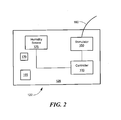
- Fig. 2 is a block diagram showing a cochlear implant system that implements sensing and control, in accordance with one embodiment of the invention
- a sensor and/or self-test module is exploited by a controller within the implant for various control and switching functions.
- the sensor may be, for example, a humidity sensor, a temperature sensor, and/or a concentration of one or more gases. Details are discussed below.
- Fig. 1 shows an exemplary cochlear implant. It is to be understood that the present invention is not limited to a cochlear prosthesis, and that the present invention is applicable to other types of implants, as known in the art.
- the cochlear implant typically includes two parts, an external component including a microphone 27 and a speech processor 29, and an implanted component 22 that includes a stimulator element 22.
- the speech processor 29 includes the power supply (batteries) of the overall system and is used to perform signal processing of the acoustic signal received by the microphone 27 to extract the stimulation parameters. Attached to the speech processor 29 is a transmitter coil 24 that transmits power and data signals to the implanted unit 22 transcutaneously via a radio frequency (RF) link.
- the implanted component 22 includes a receiver coil 24 that is capable of receiving the data and/or power from the transmitter coil 24 and a stimulator 28.
- the stimulator 28 sends stimulation signals via a cable 21 to an electrode array 20 positioned in the cochlea 12, stimulating the auditory nerve 9.
- various parts or all of the cochlear may be implanted.
- An exemplary fully implantable is described in U.S. Patent No. 6,272,382 (Faltys et al. ), incorporated herein by reference in its entirety.
- both the external component and the internal component may include a processor, with various functionality split between the two processors.
- Fig. 2 is a block diagram showing various elements of an implanted component 122 of a cochlear implant system, in accordance with one embodiment of the invention.
- the implanted component typically includes a hermetically sealed housing 128, which may be made of, without limitation, titanium, nonmagnetic stainless steel, or a ceramic.
- the implanted component 122 includes a sensor 125, such as a humidity sensor 125 which generates a signal indicative of humidity within the implant.
- the humidity sensor 125 may be, without limitation, a capacitive or resistive humidity sensor, as known in the art. It is to be understood that instead of, or in addition to, a humidity sensor, other types of sensors known in the art, such as a temperature sensor, motion sensor, and/or gas sensor, may be used in accordance with the invention described herein, that provide a signal indicative of one or more conditions, such as an environmental condition, within the implant.
- the implant may include a self-test module.
- the self-test module may initiate various tests within the implant, and/or receive input from one or more sensors, and provide a signal indicative of the performed self-test or a sensed condition.
- the self-test module may initiate, without limitation, self-test periodically or upon implant power-on.
- a controller 130 is positioned within the implanted component 122.
- the controller 130 is operationally coupled to, and receives the signal from the sensor 125 and/or self-test module.
- the controller 130 may be, for example, electrically coupled to the sensor 125 and/or self-test module.
- the controller 130 controls the implant based on the signal received from the sensor 125 and/or self-test module. Since both the controller 130 and the sensor 125 is positioned within the implanted component 122, control of the implant based on sensed signal and/or self-test is advantageously performed without having to externally send or process telemetry data, and without patient interaction.
- the controller 130 may include, without limitation, a processor (e.g., a microprocessor, microcontroller, digital signal processor, or general purpose computer), programmable logic for use with a programmable logic device (e.g., a Field Programmable Gate Array (FPGA) or other PLD), discrete components, integrated circuitry (e.g., an Application Specific Integrated Circuit (ASIC)), memory, or any other means including any combination thereof.
- a processor e.g., a microprocessor, microcontroller, digital signal processor, or general purpose computer
- programmable logic for use with a programmable logic device (e.g., a Field Programmable Gate Array (FPGA) or other PLD), discrete components, integrated circuitry (e.g., an Application Specific Integrated Circuit (ASIC)), memory, or any other means including any combination thereof.
- FPGA Field Programmable Gate Array
- ASIC Application Specific Integrated Circuit
- Memory may include, for example, a diskette, a fixed disk, a Compact Dis
- Source code may include a series of computer program instructions implemented in any of various programming languages (e.g., an object code, an assembly language, or a high-level language such as Fortran, C, C++, JAVA, or HTML) for use with various operating systems or operating environments.
- the source code may define and use various data structures and communication messages.
- the source code may be in a computer executable form (e.g., via an interpreter), or the source code may be converted (e.g., via a translator, assembler, or compiler) into a computer executable form.
- the controller 130 may command various functionality based on the signal received from the sensor 125 and/or self-test module. Deviations from a desired environmental condition may trigger the command and control. For example, in receiving signals from a humidity sensor, at the beginning ingress of humidity the controller 130 may cause stimulator 150 to stimulate electrode array 160 to produce a perceived alert to the person wearing the cochlear implant. Note that such an alert is perceived only by the person wearing the cochlear implant, who can then proceed, for example, to see an audiologist for a telemetry check (which may include reading out relative humidity). In other embodiments, the controller 130 may cause an externally audible alert when, for example, the speech processor is attached. Instead of an audible alert, other types of alerts may be provided, such as a visual alert.
- the alert provided may last for a predetermined duration upon turning on the implant. For example, when turning on the implant, three short beeps may be provided. Of course, other alerts may be provided upon further ingress, or at various levels, of humidity or other condition within the implant.
- the controller 130 may inhibit stimulation at the electrode array 160, thus avoiding any current flow at the electrodes.
- the controller 130 may switch power off in the implant and/or discharge an implanted battery 165 in a controlled fashion.
- the resonance frequency and /or the quality factor of the RF circuit on the implant side may be changed.
- a hydrophilic agent 170 such as silica gel, may be positioned in the internal component 122 to concentrate moisture at a desired location.
- the hydrophilic agent 170 may be positioned in close proximity to the humidity sensor 125. Water vapor is thus concentrated at the hydrophilic agent 170, and consequently at the humidity sensor 125, increasing the implant's sensitivity to humidity.
- the disclosed method may be implemented as a computer program product for use with a computer system.
- Such implementation may include a series of computer instructions fixed either on a tangible medium, such as a computer readable media (e.g ., a diskette, CD-ROM, ROM, or fixed disk) or transmittable to a computer system, via a modem or other interface device, such as a communications adapter connected to a network over a medium.
- Medium may be either a tangible medium (e.g ., optical or analog communications lines) or a medium implemented with wireless techniques (e.g. , microwave, infrared or other transmission techniques).
- the series of computer instructions embodies all or part of the functionality previously described herein with respect to the system.
- Such computer instructions can be written in a number of programming languages for use with many computer architectures or operating systems. Furthermore, such instructions may be stored in any memory device, such as semiconductor, magnetic, optical or other memory devices, and may be transmitted using any communications technology, such as optical, infrared, microwave, or other transmission technologies. It is expected that such a computer program product may be distributed as a removable media with accompanying printed or electronic documentation (e.g ., shrink wrapped software), preloaded with a computer system (e.g ., on system ROM or fixed disk), or distributed from a server or electronic bulletin board over the network (e.g ., the Internet or World Wide Web).
- printed or electronic documentation e.g ., shrink wrapped software
- preloaded with a computer system e.g ., on system ROM or fixed disk
- server or electronic bulletin board e.g ., the Internet or World Wide Web
Abstract
Description
- The present invention relates to implants, and more particularly, to sensing and responding to humidity or another condition within an implant.
- Often an implant is hermetically sealed to prevent build-up of moisture within the implant. The moisture buildup within the implant may adversely affect the electronic circuits within the implant. For example, moisture buildup in the implant may cause incorrect stimulation, such as over-stimulation or stimulation including direct current and/or exceeding charge density per phase limits.
- Determination of moisture build-up within an implant can be problematic. Subjective feedback from the patient regarding implant stimulation behavior is often difficult, particularly with younger patients. Another approach is to incorporate a humidity sensor/switch within the implant. An exemplary telemetry system for remotely monitoring sensed humidity within a pacemaker is disclosed in
U.S. patent no. 4,332,256 (Brownlee et al. ), which is incorporated herein by reference in its entirety. However, interpretation of telemetry data received from the implant is often difficult with corrective measures performed in an untimely and/or inconvenient manner. - In accordance with one embodiment of the invention there is provided an implant that includes a humidity sensor for generating a signal indicative of humidity within the implant. A controller within the implant receives the signal indicative of humidity, and controls the implant based on the signal indicative of humidity.
- In accordance with related embodiments of the invention, the implant may be a cochlear implant, wherein the implant includes a stimulator for stimulating an array of electrodes. The controller may inhibit output of the stimulator based on the signal indicative of humidity. The controller may control the stimulator to stimulate the electrodes so as to produce a perceived alert based on the signal indicative of humidity. The alert may be produced for a predetermined duration upon turning on of the implant.
- In accordance with further related embodiments of the invention, the controller may turn power off based on the signal indicative of humidity. The implant may include a battery, wherein the controller discharges the battery based on the signal indicative of humidity. The implant may further includes a hydrophilic agent positioned with the implant so as to direct moisture to a desired location within the implant. The humidity sensor may be positioned substantially adjacent the hydrophilic agent.
- In accordance with another embodiment of the invention, a method of controlling a cochlear implant is presented. The implant includes a stimulator for stimulating an array of electrodes. The method includes generating a signal indicative of humidity within the implant. The implant is controlled based on the signal indicative of humidity, wherein the generating and controlling is performed within the implant.
- In accordance with related embodiments of the invention, controlling the implant may include inhibiting output of the stimulator based on the signal indicative of humidity. Controlling the implant may include controlling the stimulator to stimulate the electrodes so as to produce a perceived alert based on the signal indicative of humidity. The alert may be produced for a predetermined duration upon turning on of the implant. Controlling the implant may include turning power off based on the signal indicative of humidity. The implant may include a battery, wherein controlling the implant includes discharging the battery based on the signal indicative of humidity.
- In accordance with another embodiment of the invention, an implant includes a humidity sensor for generating a signal indicative of humidity within the implant. A controller means within the implant receives the signal indicative of humidity and controls the implant based on the signal indicative of humidity.
- In accordance with related embodiments of the invention, the implant may be a cochlear implant, wherein the implant includes a stimulator for stimulating an array of electrodes. The controller means may inhibit output of the stimulator based on the signal indicative of humidity. The controller means may control the stimulator to stimulate the electrodes so as to produce a perceived alert based on the signal indicative of humidity. The alert may be produced for a predetermined duration upon turning on of the implant. The controller means may turn power off based on the signal indicative of humidity. The implant may include a battery, wherein the controller means may discharge the battery based on the signal indicative of humidity. A hydrophilic agent may be positioned with the implant so as to direct moisture to a desired location within the implant. The humidity sensor may be positioned substantially adjacent the hydrophilic agent.
- In accordance with another embodiment of the invention, a computer program product for placing within, and controlling, a cochlear implant is presented. The implant includes a stimulator for stimulating an array of electrodes, and a humidity sensor for generating a signal indicative of humidity within the implant. The computer program product includes a computer usable medium having computer readable program code thereon. The computer readable program code includes program code for controlling the implant based on the signal indicative of humidity.
- In accordance with related embodiments of the invention, the program code for controlling the implant may include program code for inhibiting output of the stimulator based on the signal indicative of humidity. The program code for controlling the implant may include program code for controlling the stimulator to stimulate the electrodes so as to produce a perceived alert based on the signal indicative of humidity. The alert may be produced for a predetermined duration upon turning on of the implant.
- In accordance with another embodiment of the invention, a method of controlling an implant includes performing a self-test at the implant. A signal indicative of a result of the performed self-test is generated. The implant is controlled based on the signal, wherein the performing, generating and controlling is performed within the implant.
- In accordance with related embodiments of the invention, the signal may be indicative of humidity. The implant may be a cochlear implant, the cochlear implant including a stimulator for stimulating an array of electrodes, and wherein controlling includes inhibiting output of the stimulator based on the signal. Controlling the implant may include controlling the stimulator to stimulate the electrodes so as to produce a perceived alert based on the signal indicative of humidity. The alert may be produced for a predetermined duration upon turning on of the implant. An externally audible alert based on the signal may be provided.
- In accordance with further related embodiments of the invention, controlling the implant may include turning power off based on the signal. The implant may include a battery, and controlling the implant may include discharging the battery based on the signal. The self-test may be initiated by the implant. The self-test may be initiated periodically or upon implant power-on.
- In accordance with another embodiment of the invention, a computer program product for placing within, and controlling, an implant, is presented. The computer program product includes computer usable medium having computer readable program code thereon. The computer readable program code includes program code for performing self-test at the implant, the self-test generating a signal indicative of a result of the performed self-test. The computer program product further includes program code for controlling the implant based on the signal.
- In accordance with related embodiments of the invention, the implant may include a humidity sensor, and the signal is indicative of humidity within the implant. The implant may include a stimulator for stimulating an array of electrodes, wherein the program code for controlling the implant includes program code for inhibiting output of the stimulator based on the signal. The program code for controlling the implant may include program code for controlling the stimulator to stimulate the electrodes so as to produce a perceived alert based on the signal. The alert may be produced for a predetermined duration upon turning on of the implant. The program code for controlling the implant may generate an externally audible alert. The program code for performing self-test may initiate the self-test, for example, periodically or upon implant power-on.
- In accordance with another embodiment of the invention, an implant includes a self test module for generating a signal indicative of a condition within the implant. A controller within the implant receives and controls the implant based on the signal.
- In accordance with related embodiments of the invention, the signal may be indicative of humidity. The implant may be a cochlear implant, wherein the implant includes a stimulator for stimulating an array of electrodes. The controller may inhibit output of the stimulator based on the signal. The controller may control the stimulator to stimulate the electrodes so as to produce a perceived alert based on the signal. The alert may be produced for a predetermined duration upon turning on of the implant. The controller may provide an externally audible alert. The controller may turn power off based on the signal. The implant may include a battery, wherein the controller discharges the battery based on the signal.
- In accordance with still another embodiment of the invention, an implant includes a sensor for generating a signal indicative of an environmental condition within the implant. A controller within the implant receives the signal indicative of the environmental condition, and controls the implant based on the signal indicative of the environmental condition.
- In related embodiments of the invention, the controller may control the implant based on a deviation of the sensed environmental condition from a desired environmental condition. The environmental condition may be a temperature, a humidity, and/or a concentration of one or more gases.
- In accordance with yet another embodiment of the invention, a method of controlling a cochlear implant is presented. The implant includes a stimulator for stimulating an array off electrodes. The method includes generating a signal indicative of an environmental condition within the implant. The implant is controlled based on the signal indicative of the environmental condition, wherein the generating and controlling is performed within the implant.
- In related embodiments of the invention, controlling the implant may be based on a deviation of the sensed environmental condition from a desired environmental condition The environmental condition may be a temperature, a humidity, and/or a concentration of one or more gases.
- The foregoing features of the invention will be more readily understood by reference to the following detailed description, taken with reference to the accompanying drawings, in which:
-
Fig. 1 shows a conventional cochlear prosthesis; and -
Fig. 2 is a block diagram showing a cochlear implant system that implements sensing and control, in accordance with one embodiment of the invention; - In illustrative embodiments, a sensor and/or self-test module is exploited by a controller within the implant for various control and switching functions. Thus, there is no need to rely on patient feedback, or interpretation of telemetry data, to monitor and react to changes in implant humidity. The sensor may be, for example, a humidity sensor, a temperature sensor, and/or a concentration of one or more gases. Details are discussed below.
-
Fig. 1 shows an exemplary cochlear implant. It is to be understood that the present invention is not limited to a cochlear prosthesis, and that the present invention is applicable to other types of implants, as known in the art. - The cochlear implant typically includes two parts, an external component including a
microphone 27 and aspeech processor 29, and an implantedcomponent 22 that includes astimulator element 22. Thespeech processor 29 includes the power supply (batteries) of the overall system and is used to perform signal processing of the acoustic signal received by themicrophone 27 to extract the stimulation parameters. Attached to thespeech processor 29 is atransmitter coil 24 that transmits power and data signals to the implantedunit 22 transcutaneously via a radio frequency (RF) link. The implantedcomponent 22 includes areceiver coil 24 that is capable of receiving the data and/or power from thetransmitter coil 24 and a stimulator 28. Based on the received data, the stimulator 28 sends stimulation signals via acable 21 to anelectrode array 20 positioned in thecochlea 12, stimulating the auditory nerve 9. It is to be understood that in various embodiments of the invention, various parts or all of the cochlear may be implanted. An exemplary fully implantable is described inU.S. Patent No. 6,272,382 (Faltys et al. ), incorporated herein by reference in its entirety. Furthermore, in various embodiments both the external component and the internal component may include a processor, with various functionality split between the two processors. -
Fig. 2 is a block diagram showing various elements of an implantedcomponent 122 of a cochlear implant system, in accordance with one embodiment of the invention. The implanted component typically includes a hermetically sealedhousing 128, which may be made of, without limitation, titanium, nonmagnetic stainless steel, or a ceramic. - The implanted
component 122 includes asensor 125, such as ahumidity sensor 125 which generates a signal indicative of humidity within the implant. Thehumidity sensor 125 may be, without limitation, a capacitive or resistive humidity sensor, as known in the art. It is to be understood that instead of, or in addition to, a humidity sensor, other types of sensors known in the art, such as a temperature sensor, motion sensor, and/or gas sensor, may be used in accordance with the invention described herein, that provide a signal indicative of one or more conditions, such as an environmental condition, within the implant. In various embodiments, the implant may include a self-test module. The self-test module may initiate various tests within the implant, and/or receive input from one or more sensors, and provide a signal indicative of the performed self-test or a sensed condition. The self-test module may initiate, without limitation, self-test periodically or upon implant power-on. - A
controller 130 is positioned within the implantedcomponent 122. Thecontroller 130 is operationally coupled to, and receives the signal from thesensor 125 and/or self-test module. In various embodiments, thecontroller 130 may be, for example, electrically coupled to thesensor 125 and/or self-test module. - In illustrative embodiments of the invention, the
controller 130 controls the implant based on the signal received from thesensor 125 and/or self-test module. Since both thecontroller 130 and thesensor 125 is positioned within the implantedcomponent 122, control of the implant based on sensed signal and/or self-test is advantageously performed without having to externally send or process telemetry data, and without patient interaction. - The
controller 130 may include, without limitation, a processor (e.g., a microprocessor, microcontroller, digital signal processor, or general purpose computer), programmable logic for use with a programmable logic device (e.g., a Field Programmable Gate Array (FPGA) or other PLD), discrete components, integrated circuitry (e.g., an Application Specific Integrated Circuit (ASIC)), memory, or any other means including any combination thereof.. Memory may include, for example, a diskette, a fixed disk, a Compact Disk (CD), Read Only Memory (ROM), Erasable Programmable Read-Only Memory (EPROM), and/or Random Access Memory (RAM). Computer program logic implementing all or part of the functionality previously described herein may be embodied in various forms, including, but in no way limited to, a source code form, a computer executable form, and various intermediate forms (e.g., forms generated by an assembler, compiler, linker, or locator.) Source code may include a series of computer program instructions implemented in any of various programming languages (e.g., an object code, an assembly language, or a high-level language such as Fortran, C, C++, JAVA, or HTML) for use with various operating systems or operating environments. The source code may define and use various data structures and communication messages. The source code may be in a computer executable form (e.g., via an interpreter), or the source code may be converted (e.g., via a translator, assembler, or compiler) into a computer executable form. - The
controller 130 may command various functionality based on the signal received from thesensor 125 and/or self-test module. Deviations from a desired environmental condition may trigger the command and control. For example, in receiving signals from a humidity sensor, at the beginning ingress of humidity thecontroller 130 may causestimulator 150 to stimulateelectrode array 160 to produce a perceived alert to the person wearing the cochlear implant. Note that such an alert is perceived only by the person wearing the cochlear implant, who can then proceed, for example, to see an audiologist for a telemetry check (which may include reading out relative humidity). In other embodiments, thecontroller 130 may cause an externally audible alert when, for example, the speech processor is attached. Instead of an audible alert, other types of alerts may be provided, such as a visual alert. - The alert provided may last for a predetermined duration upon turning on the implant. For example, when turning on the implant, three short beeps may be provided. Of course, other alerts may be provided upon further ingress, or at various levels, of humidity or other condition within the implant.
- Upon further ingress of humidity (or other condition within the implant), or at, for example, a predetermined humidity level, the
controller 130 may inhibit stimulation at theelectrode array 160, thus avoiding any current flow at the electrodes. In various embodiments, thecontroller 130 may switch power off in the implant and/or discharge an implantedbattery 165 in a controlled fashion. In still further embodiments, the resonance frequency and /or the quality factor of the RF circuit on the implant side may be changed. - In various embodiments, a
hydrophilic agent 170, such as silica gel, may be positioned in theinternal component 122 to concentrate moisture at a desired location. For example, thehydrophilic agent 170 may be positioned in close proximity to thehumidity sensor 125. Water vapor is thus concentrated at thehydrophilic agent 170, and consequently at thehumidity sensor 125, increasing the implant's sensitivity to humidity. - [0001] In various embodiments, the disclosed method may be implemented as a computer program product for use with a computer system. Such implementation may include a series of computer instructions fixed either on a tangible medium, such as a computer readable media (e.g., a diskette, CD-ROM, ROM, or fixed disk) or transmittable to a computer system, via a modem or other interface device, such as a communications adapter connected to a network over a medium. Medium may be either a tangible medium (e.g., optical or analog communications lines) or a medium implemented with wireless techniques (e.g., microwave, infrared or other transmission techniques). The series of computer instructions embodies all or part of the functionality previously described herein with respect to the system. Those skilled in the art should appreciate that such computer instructions can be written in a number of programming languages for use with many computer architectures or operating systems. Furthermore, such instructions may be stored in any memory device, such as semiconductor, magnetic, optical or other memory devices, and may be transmitted using any communications technology, such as optical, infrared, microwave, or other transmission technologies. It is expected that such a computer program product may be distributed as a removable media with accompanying printed or electronic documentation (e.g., shrink wrapped software), preloaded with a computer system (e.g., on system ROM or fixed disk), or distributed from a server or electronic bulletin board over the network (e.g., the Internet or World Wide Web).
- [0002] Although various exemplary embodiments of the invention have been disclosed, it should be apparent to those skilled in the art that various changes and modifications can be made which will achieve some of the advantages of the invention without departing from the true scope of the invention.
Claims (9)
- A cochlear implant comprising:an electrode array;a stimulator for stimulating the electrode array;a sensor for generating a signal indicative of an environmental condition within the implant; anda controller within the implant for receiving the signal and controlling the implant, based on the signal, to stimulate the electrodes so as to produce a perceived audio alert.
- The implant according to claim 1, wherein the signal is indicative of a temperature.
- The implant according to claim 1, wherein the signal is indicative of a concentration of one or more gases.
- The implant according to claim 1, wherein the controller inhibits output of the stimulator based on the signal.
- The implant according to claim 1, wherein the alert is produced for a predetermined duration upon turning on of the implant.
- The implant according to claim 1, wherein the controller provides an externally audible alert based on the signal indicative of humidity.
- The implant according to claim 1, wherein the controller turns power off based on the signal.
- The implant according to claim 1, wherein the implant includes a battery, and wherein the controller discharges the battery based on the signal.
- The implant according to claim 1, further comprising a hydrophilic agent positioned with the implant so as to direct moisture to a desired location within the implant, wherein the humidity sensor is positioned substantially adjacent the hydrophilic agent.
Applications Claiming Priority (2)
| Application Number | Priority Date | Filing Date | Title |
|---|---|---|---|
| US89068507P | 2007-02-20 | 2007-02-20 | |
| EP08730244.4A EP2136875B1 (en) | 2007-02-20 | 2008-02-20 | Implant sensor and control |
Related Parent Applications (2)
| Application Number | Title | Priority Date | Filing Date |
|---|---|---|---|
| EP08730244.4A Division EP2136875B1 (en) | 2007-02-20 | 2008-02-20 | Implant sensor and control |
| EP08730244.4A Division-Into EP2136875B1 (en) | 2007-02-20 | 2008-02-20 | Implant sensor and control |
Publications (2)
| Publication Number | Publication Date |
|---|---|
| EP2489397A1 true EP2489397A1 (en) | 2012-08-22 |
| EP2489397B1 EP2489397B1 (en) | 2016-08-24 |
Family
ID=39561251
Family Applications (2)
| Application Number | Title | Priority Date | Filing Date |
|---|---|---|---|
| EP12001627.4A Active EP2489397B1 (en) | 2007-02-20 | 2008-02-20 | Implant sensor and control |
| EP08730244.4A Active EP2136875B1 (en) | 2007-02-20 | 2008-02-20 | Implant sensor and control |
Family Applications After (1)
| Application Number | Title | Priority Date | Filing Date |
|---|---|---|---|
| EP08730244.4A Active EP2136875B1 (en) | 2007-02-20 | 2008-02-20 | Implant sensor and control |
Country Status (4)
| Country | Link |
|---|---|
| US (2) | US8620444B2 (en) |
| EP (2) | EP2489397B1 (en) |
| AU (1) | AU2008218695B2 (en) |
| WO (1) | WO2008103717A1 (en) |
Families Citing this family (12)
| Publication number | Priority date | Publication date | Assignee | Title |
|---|---|---|---|---|
| US8183998B2 (en) * | 1996-12-16 | 2012-05-22 | Ip Holdings, Inc. | System for seamless and secure networking of implantable medical devices, electronic patch devices and wearable devices |
| WO2008103717A1 (en) | 2007-02-20 | 2008-08-28 | Med-El Elektromedizinische Geraete Gmbh | Implant sensor and control |
| CA2634941A1 (en) * | 2007-06-12 | 2008-12-12 | Starkey Laboratories, Inc. | Method and apparatus for hearing assistance device using superhydrophobic coatings |
| CN102176947A (en) * | 2008-10-07 | 2011-09-07 | Med-El电气医疗器械有限公司 | Cochlear implant sound processor for sleeping with tinnitus suppression and alarm function |
| EP2348757B1 (en) * | 2009-12-31 | 2015-11-04 | Starkey Laboratories, Inc. | Foreign material mitigation for hearing assistance device components |
| DE102010043496B3 (en) * | 2010-11-05 | 2012-01-19 | Siemens Medical Instruments Pte. Ltd. | Hearing aid and method for operating a hearing aid with a humidity sensor |
| EP2493216A3 (en) | 2011-02-25 | 2014-03-12 | Starkey Laboratories, Inc. | Omniphobic perforated barrier for hearing aid transducers |
| US9071918B2 (en) | 2011-03-18 | 2015-06-30 | Starkey Laboratories, Inc. | Ball and socket connection with an acoustic seal and mounting interface for a hearing assistance device |
| WO2013112139A1 (en) * | 2012-01-24 | 2013-08-01 | Advanced Bionics Ag | Hearing assistance devices including structures that change color in response to a transition from a dry state to a wet state |
| US11128960B2 (en) * | 2012-09-25 | 2021-09-21 | Cochlear Limited | Electronic devices with protective capacity |
| US10284974B2 (en) | 2013-07-10 | 2019-05-07 | Starkey Laboratories, Inc. | Acoustically transparent barrier layer to seal audio transducers |
| JP2022549159A (en) * | 2019-09-18 | 2022-11-24 | リバイブ エレクトロニクス,エルエルシー | Method and Apparatus for Drying and/or Sanitizing Electronic Devices, Including Hearing Aid Devices |
Citations (4)
| Publication number | Priority date | Publication date | Assignee | Title |
|---|---|---|---|---|
| US4127134A (en) * | 1977-04-11 | 1978-11-28 | Cordis Corporation | Gas-absorbing pacer and method of fabrication |
| US4332256A (en) | 1976-10-28 | 1982-06-01 | Research Corporation | System for monitoring hermetic integrity, pacing pulse and load impedance in cardiac pacers |
| US4619653A (en) * | 1979-04-27 | 1986-10-28 | The Johns Hopkins University | Apparatus for detecting at least one predetermined condition and providing an informational signal in response thereto in a medication infusion system |
| US6272382B1 (en) | 1998-07-31 | 2001-08-07 | Advanced Bionics Corporation | Fully implantable cochlear implant system |
Family Cites Families (6)
| Publication number | Priority date | Publication date | Assignee | Title |
|---|---|---|---|---|
| US5571148A (en) * | 1994-08-10 | 1996-11-05 | Loeb; Gerald E. | Implantable multichannel stimulator |
| EP1293106A4 (en) * | 2000-04-11 | 2005-03-16 | Cochlear Ltd | Battery monitor and power demand adjuster |
| US6531847B1 (en) * | 2001-11-07 | 2003-03-11 | Quallion Llc | Safety method, device and system for an energy storage device |
| US7366571B2 (en) | 2004-12-10 | 2008-04-29 | Cyberonics, Inc. | Neurostimulator with activation based on changes in body temperature |
| US7571006B2 (en) * | 2005-07-15 | 2009-08-04 | Brian Gordon | Wearable alarm system for a prosthetic hearing implant |
| WO2008103717A1 (en) | 2007-02-20 | 2008-08-28 | Med-El Elektromedizinische Geraete Gmbh | Implant sensor and control |
-
2008
- 2008-02-20 WO PCT/US2008/054403 patent/WO2008103717A1/en active Application Filing
- 2008-02-20 US US12/034,264 patent/US8620444B2/en active Active
- 2008-02-20 AU AU2008218695A patent/AU2008218695B2/en active Active
- 2008-02-20 EP EP12001627.4A patent/EP2489397B1/en active Active
- 2008-02-20 EP EP08730244.4A patent/EP2136875B1/en active Active
-
2013
- 2013-12-04 US US14/096,610 patent/US20140094874A1/en not_active Abandoned
Patent Citations (4)
| Publication number | Priority date | Publication date | Assignee | Title |
|---|---|---|---|---|
| US4332256A (en) | 1976-10-28 | 1982-06-01 | Research Corporation | System for monitoring hermetic integrity, pacing pulse and load impedance in cardiac pacers |
| US4127134A (en) * | 1977-04-11 | 1978-11-28 | Cordis Corporation | Gas-absorbing pacer and method of fabrication |
| US4619653A (en) * | 1979-04-27 | 1986-10-28 | The Johns Hopkins University | Apparatus for detecting at least one predetermined condition and providing an informational signal in response thereto in a medication infusion system |
| US6272382B1 (en) | 1998-07-31 | 2001-08-07 | Advanced Bionics Corporation | Fully implantable cochlear implant system |
Also Published As
| Publication number | Publication date |
|---|---|
| EP2136875B1 (en) | 2015-08-26 |
| EP2489397B1 (en) | 2016-08-24 |
| US20140094874A1 (en) | 2014-04-03 |
| AU2008218695A1 (en) | 2008-08-28 |
| WO2008103717A1 (en) | 2008-08-28 |
| US20080200779A1 (en) | 2008-08-21 |
| US8620444B2 (en) | 2013-12-31 |
| EP2136875A1 (en) | 2009-12-30 |
| AU2008218695B2 (en) | 2011-05-26 |
Similar Documents
| Publication | Publication Date | Title |
|---|---|---|
| US8620444B2 (en) | Implant sensor and control | |
| WO2020181124A3 (en) | Evaluating stimulation eficacy for treating sleep apnea and lingual muscle tone sensing system for improved osa therapy | |
| US8315706B2 (en) | External speech processor unit for an auditory prosthesis | |
| US20050022181A1 (en) | Implantable device and programmer system which permits multiple programmers | |
| US7925350B1 (en) | Systems and methods for detecting an error associated with an implantable device | |
| US9008787B2 (en) | Active electrode state control system | |
| WO2004073491A8 (en) | Battery-powered patient implantable device | |
| US7801617B2 (en) | Automatic measurement of neural response concurrent with psychophysics measurement of stimulating device recipient | |
| CN113710312A (en) | Implantable cochlear system with integrated components and lead characterization | |
| US8798757B2 (en) | Method and device for automated observation fitting | |
| WO2005062829A3 (en) | Skull-mounted electrical stimulation system and method for treating patients | |
| CN107735145B (en) | External unit for an implantable neurostimulator system | |
| US20100087700A1 (en) | Cochlear Implant Sound Processor for Sleeping with Tinnitus Suppression and Alarm Function | |
| AU2001272189B2 (en) | Configuration of implanted devices | |
| AU2013201684B2 (en) | Implant sensor and control | |
| CN105828756B (en) | Active remote measurement for hearing implant responds | |
| US20080009919A1 (en) | Password Protection for Cochlear Implant | |
| EP2720750B1 (en) | Vestibular implant system with low battery alert | |
| US20230404440A1 (en) | Measuring presbycusis | |
| AU2007202714B2 (en) | Password protection for cochlear implant | |
| CN112512627A (en) | System and method for autonomous activation of auditory prosthesis | |
| Rajakumar et al. | Personal Computer Based Clinical Programming Software for Auditory Prostheses |
Legal Events
| Date | Code | Title | Description |
|---|---|---|---|
| PUAI | Public reference made under article 153(3) epc to a published international application that has entered the european phase |
Free format text: ORIGINAL CODE: 0009012 |
|
| AC | Divisional application: reference to earlier application |
Ref document number: 2136875 Country of ref document: EP Kind code of ref document: P |
|
| AK | Designated contracting states |
Kind code of ref document: A1 Designated state(s): AT BE BG CH CY CZ DE DK EE ES FI FR GB GR HR HU IE IS IT LI LT LU LV MC MT NL NO PL PT RO SE SI SK TR |
|
| 17P | Request for examination filed |
Effective date: 20130222 |
|
| RIC1 | Information provided on ipc code assigned before grant |
Ipc: H04R 25/00 20060101ALI20160115BHEP Ipc: A61N 1/36 20060101AFI20160115BHEP |
|
| GRAP | Despatch of communication of intention to grant a patent |
Free format text: ORIGINAL CODE: EPIDOSNIGR1 |
|
| INTG | Intention to grant announced |
Effective date: 20160329 |
|
| GRAS | Grant fee paid |
Free format text: ORIGINAL CODE: EPIDOSNIGR3 |
|
| GRAA | (expected) grant |
Free format text: ORIGINAL CODE: 0009210 |
|
| AC | Divisional application: reference to earlier application |
Ref document number: 2136875 Country of ref document: EP Kind code of ref document: P |
|
| AK | Designated contracting states |
Kind code of ref document: B1 Designated state(s): AT BE BG CH CY CZ DE DK EE ES FI FR GB GR HR HU IE IS IT LI LT LU LV MC MT NL NO PL PT RO SE SI SK TR |
|
| REG | Reference to a national code |
Ref country code: GB Ref legal event code: FG4D |
|
| REG | Reference to a national code |
Ref country code: CH Ref legal event code: EP |
|
| REG | Reference to a national code |
Ref country code: AT Ref legal event code: REF Ref document number: 822528 Country of ref document: AT Kind code of ref document: T Effective date: 20160915 |
|
| REG | Reference to a national code |
Ref country code: IE Ref legal event code: FG4D |
|
| REG | Reference to a national code |
Ref country code: DE Ref legal event code: R096 Ref document number: 602008045927 Country of ref document: DE |
|
| REG | Reference to a national code |
Ref country code: LT Ref legal event code: MG4D |
|
| REG | Reference to a national code |
Ref country code: NL Ref legal event code: MP Effective date: 20160824 |
|
| REG | Reference to a national code |
Ref country code: AT Ref legal event code: MK05 Ref document number: 822528 Country of ref document: AT Kind code of ref document: T Effective date: 20160824 |
|
| PG25 | Lapsed in a contracting state [announced via postgrant information from national office to epo] |
Ref country code: LT Free format text: LAPSE BECAUSE OF FAILURE TO SUBMIT A TRANSLATION OF THE DESCRIPTION OR TO PAY THE FEE WITHIN THE PRESCRIBED TIME-LIMIT Effective date: 20160824 Ref country code: HR Free format text: LAPSE BECAUSE OF FAILURE TO SUBMIT A TRANSLATION OF THE DESCRIPTION OR TO PAY THE FEE WITHIN THE PRESCRIBED TIME-LIMIT Effective date: 20160824 Ref country code: FI Free format text: LAPSE BECAUSE OF FAILURE TO SUBMIT A TRANSLATION OF THE DESCRIPTION OR TO PAY THE FEE WITHIN THE PRESCRIBED TIME-LIMIT Effective date: 20160824 Ref country code: NO Free format text: LAPSE BECAUSE OF FAILURE TO SUBMIT A TRANSLATION OF THE DESCRIPTION OR TO PAY THE FEE WITHIN THE PRESCRIBED TIME-LIMIT Effective date: 20161124 Ref country code: NL Free format text: LAPSE BECAUSE OF FAILURE TO SUBMIT A TRANSLATION OF THE DESCRIPTION OR TO PAY THE FEE WITHIN THE PRESCRIBED TIME-LIMIT Effective date: 20160824 Ref country code: IT Free format text: LAPSE BECAUSE OF FAILURE TO SUBMIT A TRANSLATION OF THE DESCRIPTION OR TO PAY THE FEE WITHIN THE PRESCRIBED TIME-LIMIT Effective date: 20160824 |
|
| REG | Reference to a national code |
Ref country code: FR Ref legal event code: PLFP Year of fee payment: 10 |
|
| PG25 | Lapsed in a contracting state [announced via postgrant information from national office to epo] |
Ref country code: AT Free format text: LAPSE BECAUSE OF FAILURE TO SUBMIT A TRANSLATION OF THE DESCRIPTION OR TO PAY THE FEE WITHIN THE PRESCRIBED TIME-LIMIT Effective date: 20160824 Ref country code: ES Free format text: LAPSE BECAUSE OF FAILURE TO SUBMIT A TRANSLATION OF THE DESCRIPTION OR TO PAY THE FEE WITHIN THE PRESCRIBED TIME-LIMIT Effective date: 20160824 Ref country code: GR Free format text: LAPSE BECAUSE OF FAILURE TO SUBMIT A TRANSLATION OF THE DESCRIPTION OR TO PAY THE FEE WITHIN THE PRESCRIBED TIME-LIMIT Effective date: 20161125 Ref country code: LV Free format text: LAPSE BECAUSE OF FAILURE TO SUBMIT A TRANSLATION OF THE DESCRIPTION OR TO PAY THE FEE WITHIN THE PRESCRIBED TIME-LIMIT Effective date: 20160824 Ref country code: SE Free format text: LAPSE BECAUSE OF FAILURE TO SUBMIT A TRANSLATION OF THE DESCRIPTION OR TO PAY THE FEE WITHIN THE PRESCRIBED TIME-LIMIT Effective date: 20160824 Ref country code: PT Free format text: LAPSE BECAUSE OF FAILURE TO SUBMIT A TRANSLATION OF THE DESCRIPTION OR TO PAY THE FEE WITHIN THE PRESCRIBED TIME-LIMIT Effective date: 20161226 |
|
| PG25 | Lapsed in a contracting state [announced via postgrant information from national office to epo] |
Ref country code: EE Free format text: LAPSE BECAUSE OF FAILURE TO SUBMIT A TRANSLATION OF THE DESCRIPTION OR TO PAY THE FEE WITHIN THE PRESCRIBED TIME-LIMIT Effective date: 20160824 Ref country code: RO Free format text: LAPSE BECAUSE OF FAILURE TO SUBMIT A TRANSLATION OF THE DESCRIPTION OR TO PAY THE FEE WITHIN THE PRESCRIBED TIME-LIMIT Effective date: 20160824 |
|
| REG | Reference to a national code |
Ref country code: DE Ref legal event code: R097 Ref document number: 602008045927 Country of ref document: DE |
|
| PG25 | Lapsed in a contracting state [announced via postgrant information from national office to epo] |
Ref country code: PL Free format text: LAPSE BECAUSE OF FAILURE TO SUBMIT A TRANSLATION OF THE DESCRIPTION OR TO PAY THE FEE WITHIN THE PRESCRIBED TIME-LIMIT Effective date: 20160824 Ref country code: DK Free format text: LAPSE BECAUSE OF FAILURE TO SUBMIT A TRANSLATION OF THE DESCRIPTION OR TO PAY THE FEE WITHIN THE PRESCRIBED TIME-LIMIT Effective date: 20160824 Ref country code: BE Free format text: LAPSE BECAUSE OF FAILURE TO SUBMIT A TRANSLATION OF THE DESCRIPTION OR TO PAY THE FEE WITHIN THE PRESCRIBED TIME-LIMIT Effective date: 20160824 Ref country code: CZ Free format text: LAPSE BECAUSE OF FAILURE TO SUBMIT A TRANSLATION OF THE DESCRIPTION OR TO PAY THE FEE WITHIN THE PRESCRIBED TIME-LIMIT Effective date: 20160824 Ref country code: SK Free format text: LAPSE BECAUSE OF FAILURE TO SUBMIT A TRANSLATION OF THE DESCRIPTION OR TO PAY THE FEE WITHIN THE PRESCRIBED TIME-LIMIT Effective date: 20160824 Ref country code: BG Free format text: LAPSE BECAUSE OF FAILURE TO SUBMIT A TRANSLATION OF THE DESCRIPTION OR TO PAY THE FEE WITHIN THE PRESCRIBED TIME-LIMIT Effective date: 20161124 |
|
| PLBE | No opposition filed within time limit |
Free format text: ORIGINAL CODE: 0009261 |
|
| STAA | Information on the status of an ep patent application or granted ep patent |
Free format text: STATUS: NO OPPOSITION FILED WITHIN TIME LIMIT |
|
| 26N | No opposition filed |
Effective date: 20170526 |
|
| PG25 | Lapsed in a contracting state [announced via postgrant information from national office to epo] |
Ref country code: SI Free format text: LAPSE BECAUSE OF FAILURE TO SUBMIT A TRANSLATION OF THE DESCRIPTION OR TO PAY THE FEE WITHIN THE PRESCRIBED TIME-LIMIT Effective date: 20160824 |
|
| PG25 | Lapsed in a contracting state [announced via postgrant information from national office to epo] |
Ref country code: MC Free format text: LAPSE BECAUSE OF FAILURE TO SUBMIT A TRANSLATION OF THE DESCRIPTION OR TO PAY THE FEE WITHIN THE PRESCRIBED TIME-LIMIT Effective date: 20160824 |
|
| REG | Reference to a national code |
Ref country code: CH Ref legal event code: PL |
|
| GBPC | Gb: european patent ceased through non-payment of renewal fee |
Effective date: 20170220 |
|
| PG25 | Lapsed in a contracting state [announced via postgrant information from national office to epo] |
Ref country code: CH Free format text: LAPSE BECAUSE OF NON-PAYMENT OF DUE FEES Effective date: 20170228 Ref country code: LI Free format text: LAPSE BECAUSE OF NON-PAYMENT OF DUE FEES Effective date: 20170228 |
|
| REG | Reference to a national code |
Ref country code: IE Ref legal event code: MM4A |
|
| PG25 | Lapsed in a contracting state [announced via postgrant information from national office to epo] |
Ref country code: LU Free format text: LAPSE BECAUSE OF NON-PAYMENT OF DUE FEES Effective date: 20170220 |
|
| REG | Reference to a national code |
Ref country code: FR Ref legal event code: PLFP Year of fee payment: 11 |
|
| PG25 | Lapsed in a contracting state [announced via postgrant information from national office to epo] |
Ref country code: GB Free format text: LAPSE BECAUSE OF NON-PAYMENT OF DUE FEES Effective date: 20170220 Ref country code: IE Free format text: LAPSE BECAUSE OF NON-PAYMENT OF DUE FEES Effective date: 20170220 |
|
| PG25 | Lapsed in a contracting state [announced via postgrant information from national office to epo] |
Ref country code: MT Free format text: LAPSE BECAUSE OF NON-PAYMENT OF DUE FEES Effective date: 20170220 |
|
| PG25 | Lapsed in a contracting state [announced via postgrant information from national office to epo] |
Ref country code: HU Free format text: LAPSE BECAUSE OF FAILURE TO SUBMIT A TRANSLATION OF THE DESCRIPTION OR TO PAY THE FEE WITHIN THE PRESCRIBED TIME-LIMIT; INVALID AB INITIO Effective date: 20080220 |
|
| PG25 | Lapsed in a contracting state [announced via postgrant information from national office to epo] |
Ref country code: CY Free format text: LAPSE BECAUSE OF NON-PAYMENT OF DUE FEES Effective date: 20160824 |
|
| PG25 | Lapsed in a contracting state [announced via postgrant information from national office to epo] |
Ref country code: TR Free format text: LAPSE BECAUSE OF FAILURE TO SUBMIT A TRANSLATION OF THE DESCRIPTION OR TO PAY THE FEE WITHIN THE PRESCRIBED TIME-LIMIT Effective date: 20160824 |
|
| PG25 | Lapsed in a contracting state [announced via postgrant information from national office to epo] |
Ref country code: IS Free format text: LAPSE BECAUSE OF FAILURE TO SUBMIT A TRANSLATION OF THE DESCRIPTION OR TO PAY THE FEE WITHIN THE PRESCRIBED TIME-LIMIT Effective date: 20161224 |
|
| PGFP | Annual fee paid to national office [announced via postgrant information from national office to epo] |
Ref country code: FR Payment date: 20230223 Year of fee payment: 16 |
|
| PGFP | Annual fee paid to national office [announced via postgrant information from national office to epo] |
Ref country code: DE Payment date: 20230227 Year of fee payment: 16 |