EP2492460A2 - Valve train device and cylinder head provided with same - Google Patents
Valve train device and cylinder head provided with same Download PDFInfo
- Publication number
- EP2492460A2 EP2492460A2 EP12156314A EP12156314A EP2492460A2 EP 2492460 A2 EP2492460 A2 EP 2492460A2 EP 12156314 A EP12156314 A EP 12156314A EP 12156314 A EP12156314 A EP 12156314A EP 2492460 A2 EP2492460 A2 EP 2492460A2
- Authority
- EP
- European Patent Office
- Prior art keywords
- valve
- spring
- surface portion
- bearing surface
- cylinder head
- Prior art date
- Legal status (The legal status is an assumption and is not a legal conclusion. Google has not performed a legal analysis and makes no representation as to the accuracy of the status listed.)
- Granted
Links
Images


Classifications
-
- F—MECHANICAL ENGINEERING; LIGHTING; HEATING; WEAPONS; BLASTING
- F01—MACHINES OR ENGINES IN GENERAL; ENGINE PLANTS IN GENERAL; STEAM ENGINES
- F01L—CYCLICALLY OPERATING VALVES FOR MACHINES OR ENGINES
- F01L13/00—Modifications of valve-gear to facilitate reversing, braking, starting, changing compression ratio, or other specific operations
- F01L13/0005—Deactivating valves
-
- F—MECHANICAL ENGINEERING; LIGHTING; HEATING; WEAPONS; BLASTING
- F01—MACHINES OR ENGINES IN GENERAL; ENGINE PLANTS IN GENERAL; STEAM ENGINES
- F01L—CYCLICALLY OPERATING VALVES FOR MACHINES OR ENGINES
- F01L1/00—Valve-gear or valve arrangements, e.g. lift-valve gear
- F01L1/12—Transmitting gear between valve drive and valve
- F01L1/14—Tappets; Push rods
- F01L1/143—Tappets; Push rods for use with overhead camshafts
-
- F—MECHANICAL ENGINEERING; LIGHTING; HEATING; WEAPONS; BLASTING
- F01—MACHINES OR ENGINES IN GENERAL; ENGINE PLANTS IN GENERAL; STEAM ENGINES
- F01L—CYCLICALLY OPERATING VALVES FOR MACHINES OR ENGINES
- F01L1/00—Valve-gear or valve arrangements, e.g. lift-valve gear
- F01L1/46—Component parts, details, or accessories, not provided for in preceding subgroups
- F01L1/462—Valve return spring arrangements
-
- F—MECHANICAL ENGINEERING; LIGHTING; HEATING; WEAPONS; BLASTING
- F01—MACHINES OR ENGINES IN GENERAL; ENGINE PLANTS IN GENERAL; STEAM ENGINES
- F01L—CYCLICALLY OPERATING VALVES FOR MACHINES OR ENGINES
- F01L3/00—Lift-valve, i.e. cut-off apparatus with closure members having at least a component of their opening and closing motion perpendicular to the closing faces; Parts or accessories thereof
- F01L3/10—Connecting springs to valve members
-
- F—MECHANICAL ENGINEERING; LIGHTING; HEATING; WEAPONS; BLASTING
- F01—MACHINES OR ENGINES IN GENERAL; ENGINE PLANTS IN GENERAL; STEAM ENGINES
- F01L—CYCLICALLY OPERATING VALVES FOR MACHINES OR ENGINES
- F01L1/00—Valve-gear or valve arrangements, e.g. lift-valve gear
- F01L1/46—Component parts, details, or accessories, not provided for in preceding subgroups
- F01L2001/467—Lost motion springs
-
- F—MECHANICAL ENGINEERING; LIGHTING; HEATING; WEAPONS; BLASTING
- F02—COMBUSTION ENGINES; HOT-GAS OR COMBUSTION-PRODUCT ENGINE PLANTS
- F02B—INTERNAL-COMBUSTION PISTON ENGINES; COMBUSTION ENGINES IN GENERAL
- F02B61/00—Adaptations of engines for driving vehicles or for driving propellers; Combinations of engines with gearing
- F02B61/02—Adaptations of engines for driving vehicles or for driving propellers; Combinations of engines with gearing for driving cycles
Definitions
- the present invention relates to a valve train device installed in a cylinder head of an engine, more particularly, to a valve train device including a valve resting mechanism, and also relates to a cylinder head of the engine provided with the valve train device.
- a conventionally known valve train device of an engine of, for example, a vehicle includes a valve resting mechanism that holds a poppet valve (intake valve and exhaust valve) in a closed position irrespective of an operation of a camshaft of an engine, for example, as disclosed in Japanese Patent Application Laid-Open Publication No. 2000-87711 (Patent Document 1).
- the valve train device described in Patent Document 1 is mounted to a cylinder head of the engine and configured to transmit power from a camshaft to the poppet valve via a valve tappet.
- the valve tappet includes a lost motion unit that temporarily interrupts power transmission from the camshaft to the poppet valve.
- the lost motion unit is constructed so as to be hydraulically switchable between an interlocking state and a non-interlocking state between the valve tappet and an upper end of a stem portion of the poppet valve.
- the lost motion unit transmits a vertical motion of the valve tappet in accordance with rotation of the camshaft to the poppet valve, and operates to open or close the poppet valve, for example, during middle speed rotation or high speed rotation of the engine.
- the lost motion unit temporality interrupts power transmission to the poppet valve irrespective of the vertical motion of the valve tappet, for example, during low speed rotation of the engine, and holds the poppet valve in the closed position.
- valve train device described above includes the lost motion unit between the camshaft and the poppet valve, a size or dimension of the valve train device is increased in a driving direction of the poppet valve, which may result in increase in sizes of components such as a cylinder head and a head cover that house the valve train device, and hence, increasing height of the entire engine.
- This makes it difficult to ensure an installation space for the engine, and increases weight of the engine, and furthermore, the increase in the size or dimension of the engine further requires production of a dedicated component, which may result in increasing in the production costs.
- the present invention was conceived in view of the circumstances encountered in the prior art mentioned above and an object thereof is to provide a valve train device provided with a lost motion unit without increasing height of an engine of a vehicle, and also provide a cylinder head of an engine equipped with such valve train device.
- a valve train device installed in a cylinder head of an engine and driven by a camshaft of the engine, the valve train device includes: a valve unit including an intake valve and an exhaust valve communicated with a combustion chamber of an engine, each of the intake valve and exhaust valve having a linearly extending stem portion and driven in an extending direction of the stem portion to open/close an intake port or exhaust port communicating with the combustion chamber of the engine; a valve lifter disposed between one end side of the stem portion located apart from the combustion chamber and the camshaft so as to transmit power from the camshaft to the valve unit; a lost motion unit that interrupts power transmission from the valve lifter to the valve unit; a first spring urging the valve unit in a direction to close the intake valve or exhaust valve; and a second spring having a diameter lager than that of the first spring and urging the lost motion unit against the valve lifter, in which another end side of the second spring is disposed at a portion closer to one
- the narrow portion of the installation portion of the valve train device in the cylinder head can be placed in a dead space near the fluid path of the cylinder head, thus contributing the absorption of an increase in size of the valve train device by the lost motion unit, and preventing an increase in height of the engine.
- an installation space for the engine can be ensured and the weight of the engine can be reduced.
- the installed portion of the valve train device is narrow on the other end side of the stem portion, thereby preventing the valve train device from protruding from the dead space of the cylinder head into the fluid path.
- the first spring is installed in the cylinder head through the first spring seat
- the second spring is installed in the cylinder head via the second spring seat
- the first spring seat has an outer bearing surface portion that receives an end of the second spring on the other end side in the extending direction of the stem portion
- the second spring seat has an inner bearing surface portion that receives an end of the first spring on the other end side in the extending direction of the stem portion
- the first spring has an end surface portion exposed between the first spring seat and the second spring seat.
- the spring seat integrally holds the first spring and the second spring, thereby preventing dismounting or removal of the first spring and the second spring during assembling.
- the installation portion of the valve train device in the cylinder head is made to be further narrower on the other end side of the stem portion.
- a cylinder head of an engine which includes: an intake port; an exhaust port; a valve unit including an intake valve and an exhaust valve to open/close the intake port and the exhaust port; and a valve train device that drives the valve unit, wherein the valve train device includes a cam shaft, a valve lifter driven by a cam mounted to the cam shaft to be integrally rotatable, a lost motion unit that interrupts power transmission from the valve lifter to the valve unit, a first spring urging the valve unit in a direction to close the intake valve or exhaust valve, and a second spring having a diameter lager than that of the first spring and urging the lost motion unit against the valve lifter, and wherein the cylinder head is provided with an inner bearing surface portion to which the first spring is fitted and an outer bearing surface portion to which the second spring is fitted, in which the outer bearing surface portion is positioned closer to the valve lifter than the inner bearing surface portion, and the inner bearing surface portion and the outer bearing surface portion have configuration such that a virtual line connecting
- valve train device of the present invention is herein specifically applied to an engine, i.e., cylinder head thereof, of a vehicle of a naked type motorcycle will be described, but the present invention is not limited to this embodiment and other modifications or alternations may be applied to an engine (engine unit) of motorcycles of other types, four-wheel vehicles, boats such as outboard motor, or the like. It is further to be noted that terms “upper”, “lower”, “right”, “left” and like terms representing direction are used herein with reference to the illustration of the drawings as far as specific other description is not made.
- a front side of a vehicle body is shown by an arrow FR and a rear of the vehicle body is shown by an arrow RE.
- a motorcycle 1 includes a vehicle body frame structure 2 made of steel or aluminum alloy, and components such as a power unit and an electric system are mounted thereto.
- a main frame 21 of the vehicle body frame structure 2 is laterally bifurcated rearward from a head pipe 22 at a front end and slopes rearward downward.
- An engine unit 3 is suspended from a lower portion of the main frame 21.
- a fuel tank 4 is placed on an upper portion of the main frame 21.
- a driver seat 5a and a passenger seat 5b are connected to upper portions of a pair of left and right seat rails, not shown, connected to a rear portion of the main frame 21 on the rear of the fuel tank 4.
- the seat rails extend rearward and upward from the rear portion of the main frame 21 and support the driver seat 5a and the passenger seat 5b together with reinforcing seat pillars 23.
- Handlebars 51 for the passenger are provided on left and right frame covers of the passenger seat 5b.
- foot rests 52 and 53 are provided correspondingly in positions.
- a shift pedal 54 is provided in front of the driver foot rest 52 on the left side of the vehicle body and a brake pedal, not shown, for a rear wheel 6 is provided in front of the driver foot rest 52 on the right side of the vehicle body.
- a pair of front forks 71 is laterally and swingably supported via a steering shaft mounted to the head pipe 22 on an upper side of the front portion of the vehicle body frame 2.
- Grips 73 are mounted to opposite ends of the handlebars in upper portions of the pair of front forks 71.
- a clutch lever 74 is provided on the handlebar on the left side of the vehicle body, and a brake lever, not shown, for a front wheel 7 is provided on the handlebar on the right side of the vehicle body.
- the front wheel 7 is rotatably supported and a front fender 75 that covers the upper portion of the front wheel 7 is also placed.
- the front wheel 7 is provided with a brake disk 76.
- a swing arm 61 is vertically swingably connected to a lower side of the rear portion of the vehicle body frame 2, and a suspension 62 for absorbing shock on the rear wheel is mounted between the vehicle body frame 2 and the swing arm 61.
- the rear wheel 6 is rotatably supported by the rear portion of the swing arm 61.
- a driven sprocket 63 is provided on the rear wheel 6, and a chain 64 is stretched between the driven sprocket 63 and a drive sprocket on the engine side.
- the rear wheel 6 is rotationally driven by power transmitted from the engine via the chain 64.
- An upper portion of the chain 64 is covered with a chain cover 65, and an upper portion of the rear wheel 6 is covered with a rear fender 66 placed on the rear side of the passenger seat 5b.
- the engine unit 3 includes, for example, a four-cycle V-type two-cylinder engine and a transmission, and is supported by the main frame 21 via an engine mount.
- the engine unit 3 is a horizontal crank type in which a crankshaft is located in a vehicle width direction, and two front and rear cylinders are disposed in a V-shape arrangement in a crankcase 31 that houses the crankshaft.
- Air is taken into the engine unit 3 through an intake pipe 32 (see Fig. 3 ), the air is mixed with fuel in a fuel injection device and supplied to a combustion chamber 355.
- An exhaust gas after combustion in the engine is exhausted from a muffler 34 through an exhaust pipe 33 extending downward from the engine unit 3.
- a head lamp 91 is provided in front of the front fork 71, and a pair of left and right front winkers 92 are provided on opposite sides of the head lamp 91.
- a meter unit 93 that indicates speed, engine rpm, and fuel level is provided on an upper portion of the head lamp 91.
- a rearview mirror 95 is supported by the handlebar through a stay 94.
- a pair of left and right rear winkers 96 are provided on a rear side of the rear fender 66, and a combination lamp 97 is installed on a rear side of the rear winker 96.
- a plurality of covers as a vehicle body exterior covers forming outer configuration are provided on the vehicle body frame 2 or the like so as to provide unity of outer appearance of the vehicle body.
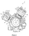
- Fig. 2 is a side view of the engine unit according to the embodiment
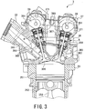
- Fig. 3 is a partial sectional view of the engine unit
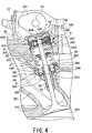
- Fig. 4 is an enlarged view of the valve train device around the valve train mechanism on an intake side in Fig. 3
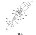
- Fig. 5 is a perspective view of the valve train device.
- an outer spring and an inner spring are omitted for the sake of convenience of the description.
- the engine unit 3 has a contour configured by mounting two front and rear cylinder blocks 35 on the crankcase 31 in V-shape and mounting a cylinder head 36 and a head cover 37 to each of the cylinder blocks 35.
- the crankcase 31 houses the crankshaft, not shown, so as to extend in a vehicle width direction.
- a plurality of cylinder bores 351 are formed so as to be arranged laterally in the vehicle width direction, and a piston 352 is housed in each cylinder bore 351 to be vertically and reciprocally movable.
- the piston 352 is connected to the crankshaft via a connecting rod 353.
- the cylinder head 36 includes an intake port (fluid path or passage) 361 that feeds air into the engine, and an exhaust port (fluid path or passage) 362 that delivers an exhaust gas to the outside of the engine unit.
- the cylinder head 36 also includes an intake valve 81 that opens/closes the intake port 361, and an exhaust valve 82 that opens/closes the exhaust port 362.
- the intake port 361 and the exhaust port 362 communicate with the combustion chamber 355 defined by a lower surface of the cylinder head 36 and an upper surface of the piston 352 in the cylinder bore 351.
- An ignition plug, now shown, provided in the cylinder head 36 is disposed so as to protrude in an upper portion of the combustion chamber 355.
- the engine unit 3 is a direct acting DOHC (Double OverHead Camshaft) engine, and includes a pair of camshafts 39 independently provided on the intake side and the exhaust side in a fashion corresponding to the valve train devices 8.
- the pair of camshafts 39 extend in the vehicle width direction in the upper portion of the cylinder head 36, and each camshaft is provided with a cam 391.
- each of the pair of camshafts 39 is connected to the crankshaft through a valve lifter such as a sprocket and a cam chain.
- the rotational motion of the crankshaft is transmitted to the pair of camshafts 39 through the valve lifter to operate the valve train devices 8 on the intake side and the exhaust side.
- installation spaces 364 for the pair of valve train devices 8 are formed above the intake port 361 and the exhaust port 362.
- the installation space 364 communicates with a housing space 371 housing the camshaft 39 at an upper portion, and is partitioned by an outer wall portion 365 of the intake port 361 or the exhaust port 362 at a lower portion.
- the pair of valve train devices 8 are provided in the installation spaces 364 with the intake valve 81 and the exhaust valve 82 protruding into the intake port 361 and the exhaust port 362 from the outer wall portion 365.
- valve train device 8 on the intake side is configured to transmit power from the camshaft 39 to the intake valve 81 via a valve tappet 83, that is one of power transmission components such as valve lifter or valve tappet, in contact with the cam 391.
- the valve tappet 83 has a cylindrical configuration having a closed upper end and an opened lower end, and is placed between an upper end of the intake valve 81 and the camshaft.
- a lost motion unit 84 that temporarily interrupts power transmission from the camshaft 39 to the intake valve 81 is provided in the valve tappet 83.
- the lost motion unit 84 is formed so as to be hydraulically switchable between an interlocking state and a non-interlocking state between the valve tappet 83 and the stem portion 811 of the intake valve 81.
- an oil passage 367 for driving the lost motion unit 84 is formed in a side wall portion 366 that supports the valve tappet 83.
- the intake valve 81 includes a linearly extending stem portion 811 and an umbrella portion 812 provided at a lower end of the stem portion 811.
- the stem portion 811 of the intake valve 81 is passed through the valve guide 85 provided in the outer wall portion 365, and supported reciprocally movably toward the combustion chamber 355.
- the valve tappet 83 and the intake valve 81 are urged by the outer spring (second spring) 86 and the inner spring (first spring) 87 concentrically placed in the installation space 364.
- the valve tappet 83 is pressed against the camshaft 39 by the outer spring 86, and the intake valve 81 is urged in a valve closing operation direction, toward the camshaft, by the inner spring 87 via a retainer 88 secured to the stem portion 811.
- the outer wall portion 365 is generally a dead space S of the cylinder block 35.
- An annular recess 363 is formed around the valve guide 85 of the outer wall portion 365.
- a bottom surface of the recess 363 is formed as a support surface 369 for the inner spring 87 formed in a position deeper than a support surface 368 for the outer spring 86.
- a lower end of the inner spring 87 is positioned closer to the combustion chamber 355 than a lower end of the outer spring 86 in an extending direction of the stem portion 811.
- the recess 363 is formed in the dead space S of the cylinder head 36, and thus the entire valve train device 8 is installed in a low position.
- only the lower end of the inner spring 87 having a small diameter is located in the dead space S, thereby preventing the valve train device 8 from protruding into the intake port 361 or minimizing such protrusion thereof.
- the outer spring 86 and the inner spring 87 are supported by the support surfaces 368 and 369 of the cylinder head 36 through the spring seat 89.
- the spring seat 89 is formed of synthetic resin or metal into a stepped cylindrical shape and mounted around the valve guide 85.
- the spring seat 89 includes an outer bearing surface portion 891 that receives the lower end of the outer spring 86, an inner bearing surface portion 892 that receives the lower end of the inner spring 87, and a side surface portion 893 that connects an inner peripheral edge of the outer bearing surface portion 891 and an outer peripheral edge of the inner bearing surface portion 892.
- An annular holding portion 894 for retaining the outer spring 86 stands on an outer edge of the outer bearing surface portion 891, and an annular holding portion 895 for retaining the inner spring 87 stands on an inner edge of the inner bearing surface portion 892.
- the spring seat 89 has the outer bearing surface portion 891 and the inner bearing surface portion 892 integrally formed, and further includes the annular holding portions 894 and 895, thereby preventing the springs 86 and 87 from removing and facilitating assembly of the valve train device 8.
- the side surface portion 893 of the spring seat 89 is interposed between a surface on the lower end side of the inner spring 87 and the inner peripheral surface of the recess 363 in the cylinder head 36.
- the downward movement of the valve tappet 83 by the rotation of the camshaft 39 is transmitted to the intake valve 81 through the lost motion unit 84.
- the intake valve 81 is pressed downward in a valve opening direction to thereby open the intake port 361.
- the valve tappet 83 and the intake valve 81 pressed downward are urged backward (i.e., returned) by the outer spring 86 and the inner spring 87 so as to close the intake port 361.
- the lost motion unit 84 is in the non-interlocking state, the power transmission to the intake valve 81 is interrupted to maintain the closed state of the valve.
- the lost motion unit 84 includes a cylindrical plunger holder 841 mounted in the valve tappet 83 and a plunger 842 slidably held in the diametrical direction in the plunger holder 841.
- An upper surface of the plunger holder 841 is engaged with an upper surface of the valve tappet 83, and a lower surface of the plunger holder 841 is engaged with an upper end of the outer spring 86.
- the valve tappet 83 is pressed against the camshaft 39 via the plunger holder 841 by the outer spring 86.
- a shallow groove 843 is formed in the entire outer peripheral surface of the plunger holder 841.
- the oil passage 367 formed in the cylinder head 36 is connected to the shallow groove 843.
- a plunger hole 844 is formed in the plunger holder 841 so as to extend in the diametrical direction thereof.
- the plunger hole 844 has one opened end and the other closed end, and the plunger 842 is housed therein in the slidable manner.
- a spring housing portion 845 cylindrically recessed from the end surface of the plunger hole 844 is formed to the end of the plunger 842 located on the closed side of the plunger hole 844.
- a return spring 846 that urges the plunger 842 toward the opening in the plunger hole 844 is housed between a back surface (a surface in a deep side) of the spring housing portion 845 and a back surface (a surface in a deep side) of the plunger hole 844.
- a through hole 847 is formed to the plunger 842 so as to be capable of entering into and out of the upper end of the stem portion 811 through the plunger 842 in the vertical direction perpendicular to the extending direction.
- the plunger 842 pressed backward by the return spring 846 may be positioned by a positioning member or the like.
- the lost motion unit 84 is not limited to the above configuration and may take any mechanism configuration that can interrupt the power transmission from the valve tappet 83 to the intake valve 81.
- the valve train device 8 on the exhaust side has substantially the same configuration and arrangement as those of the valve train device 8 on the intake side, and the description thereof will be omitted herein.
- FIG. 6 illustrates the installed structure or arrangement of the valve train device according to the present embodiment.
- the right side represents the valve train device according to the embodiment of the present invention and the left side view represents a valve train device according to a comparative example.
- the valve train device according to the comparative example is different from the valve train device according to the present embodiment on the right side in that an outer spring and an inner spring are supported by the same support surface.
- the same terms as in the embodiment are denoted by the same reference numerals for the sake of easy understanding of the explanation.
- the valve train device on the exhaust side has substantially the same installed structure or configuration as that of the valve train device on the intake side, and the description thereof is hence omitted herein.
- an outer spring 86 and an inner spring 87 are supported by the same support surface 368 of the cylinder head 36.
- a length L1 of the outer spring 86 is longer than a length L2 of the inner spring 87, and the lost motion unit 84 is spaced by a distance L3 from a retainer 88 secured to a stem portion 811.
- the distance L3 ensures a moving length of the stem portion 811 into and out of a through hole 847 in a plunger 842 during a lost motion, thereby providing establishment of the non-interlocking state between a valve tappet 83 and an intake valve 81.
- the lost motion unit 84 provided in the valve train device 8 of the comparative example increases a size of the valve train device 8 in a driving direction of the intake valve 81.
- components such as the cylinder head 36 and a head cover 37 that house the valve train device 8 are also increased in size, hence increasing the height of the engine.
- the valve train device 8 according to the comparative example requires a dedicated component corresponding to an increase in size of the valve train device, thereby increasing production costs.
- a long stem portion 811 of the intake valve 81 needs to be formed to achieve the lost motion.
- the outer spring 86 is supported by the support surface 368, and the inner spring 87 is supported by the support surface 369 in a position deeper than the outer spring 86.
- the outer spring 86 having a length L4 shorter than the length L1 of the outer spring 86 in the comparative example can ensure a distance L3 between the retainer 88 and the lost motion unit 84.
- the length of the outer spring 86 can be reduced by a distance "a" between the support surface 368 and the lower end of the inner spring 87 as compared to the comparative example.
- the length of the outer spring 86 can be reduced, and thus, the valve tappet 83 and the lost motion unit 84 can be placed at a low position.
- This arrangement can contribute to absorb an increase in size of the valve train device 8 by the lost motion unit 84 and to prevent an increase in height of the engine unit. Further, the need for a dedicated component due to the increase in height of the engine unit is eliminated, resulting in the reduction of the production costs. According to the present embodiment, as shown in right side illustration of Fig.
- valve tappet 83 and the lost motion unit 84 are placed in a low position, and thus, a stem portion 811 having short length can be formed, and for example, the intake valve 81 of the valve train device 8 without the lost motion unit 84 can be used.
- a width W2 defined by the side surface portion 893 at the lower end of the inner spring 87 can be formed to be narrower than a width W1 defined by the annular holding portion 894 at the lower end of the outer spring 86. Accordingly, in the valve train device 8 of the present embodiment, the installation portion (specifically, a region from the valve tappet 83 to the spring seat 89) in the cylinder head 36 is narrower on the lower end side than the upper end side of the stem portion 811.
- valve train device 8 can be prevented from protruding into the intake port 361 or minimizing the protruding distance, thus being advantages and effective.
- the end of the inner spring 87 having a diameter smaller than that of the outer spring 86 is disposed in the dead space S of the cylinder head 36, thereby preventing the springs 86 and 87 from protruding into the intake port 361 and the exhaust port 362 or minimizing the protrusion entering therein, and preventing an increase in height of the engine with a simple configuration, thereby absorbing an increase in size of the valve train device 8 by the lost motion unit 84, and preventing an increase in height of the engine (engine unit). Therefore, an installation space for the engine unit can be ensured, and the weight of the engine can be reduced. Further, a location of dedicated component due to the increase in height of the engine is not needed, so that the production costs can be reduced.
- valve train device 8 includes the spring seat 89 having the outer bearing surface portion 891 and the inner bearing surface portion 892 integrally formed
- a separately formed spring seat may be provided as in a valve train device 8 as a modified example such as shown in Figs. 7 and 8 , in which the valve train device is different from the valve train device according to the described embodiment only in the separately formed spring seat.
- FIG. 7 is a perspective view of a valve train device according to a modified example
- Fig. 8 is a sectional view of the valve train device of the modified example.
- the same terms as in the embodiment are denoted by the same reference numerals.
- the valve train device 8 includes a spring seat (second spring seat) 89a for an outer spring 86, and a spring seat (first spring seat) 89b for an inner spring 87.
- the spring seat 89a includes an outer bearing surface portion 891 that receives a lower end of the outer spring 86 and a retaining annular holding portion 894 standing on an outer edge of the outer bearing surface portion 891.
- the spring seat 89b includes an inner bearing surface portion 892 that receives the lower end of the inner spring 87 and a retaining annular holding portion 895 standing on an inner edge of the inner bearing surface portion 892.
- the spring seats 89a and 89b have configurations of the spring seat 89 with the side surface portion 893 removed, and a surface of the lower end of the inner spring 87 is exposed between the spring seats 89a and 89b.
- a valve train device installed in a cylinder head of an engine and driven by a camshaft of the engine.
- the valve train device includes a valve unit including an intake valve and an exhaust valve communicated with a combustion chamber of an engine, each of the intake valve and exhaust valve having a linearly extending stem portion and driven in an extending direction of the stem portion to open/close an intake port or exhaust port communicating with the combustion chamber; a valve lifter as a power transmission mechanism disposed between one end side of the stem portion located apart from the combustion chamber and the camshaft so as to transmit power from the camshaft to the valve unit; and a lost motion unit that interrupts power transmission from the valve lifter to the valve unit.
- the valve train device further includes a first spring urging the valve unit in a direction to close the intake valve or exhaust valve, and a second spring having a diameter larger than that of the first spring and urging the lost motion unit against the valve lifter, in which another end side of the second spring is disposed at a portion closer to one end side of the stem portion than a location of another end side of the first spring with respect to the cylinder head.
- a cylinder head of an engine provided with an intake port and an exhaust port, and includes an intake valve and an exhaust valve to open/close the intake port and the exhaust port, and a valve train device that drives the intake valve and/ or exhaust valve.
- the valve train device includes a valve unit and other components mentioned above, wherein the cylinder head is provided with an inner bearing surface portion to which the first spring is fitted and an outer bearing surface portion to which the second spring is fitted, in which the outer bearing surface portion is positioned closer to the valve lifter than the inner bearing surface portion, and the inner bearing surface portion and the outer bearing surface portion have configuration such that a virtual line (VL in Fig. 4 ) connecting an outer edge portion of the inner bearing surface portion and an outer edge portion of the outer bearing surface portion is substantially parallel to an inner peripheral wall surface of the intake port or exhaust port as viewed in an axial direction of the valve unit.
- VL in Fig. 4 virtual line connecting an outer edge portion of the inner bearing surface portion and an outer edge portion of the outer bearing surface portion is substantially parallel to an inner peripheral wall surface
- valve train device of the structure mentioned above can provide advantageous effects and/or functions as those mentioned with reference to the valve train device.
Abstract
Description
- The present invention relates to a valve train device installed in a cylinder head of an engine, more particularly, to a valve train device including a valve resting mechanism, and also relates to a cylinder head of the engine provided with the valve train device.
- A conventionally known valve train device of an engine of, for example, a vehicle, includes a valve resting mechanism that holds a poppet valve (intake valve and exhaust valve) in a closed position irrespective of an operation of a camshaft of an engine, for example, as disclosed in Japanese Patent Application Laid-Open Publication No.
2000-87711 - The lost motion unit is constructed so as to be hydraulically switchable between an interlocking state and a non-interlocking state between the valve tappet and an upper end of a stem portion of the poppet valve. The lost motion unit transmits a vertical motion of the valve tappet in accordance with rotation of the camshaft to the poppet valve, and operates to open or close the poppet valve, for example, during middle speed rotation or high speed rotation of the engine. Furthermore, the lost motion unit temporality interrupts power transmission to the poppet valve irrespective of the vertical motion of the valve tappet, for example, during low speed rotation of the engine, and holds the poppet valve in the closed position.
- However, since the valve train device described above includes the lost motion unit between the camshaft and the poppet valve, a size or dimension of the valve train device is increased in a driving direction of the poppet valve, which may result in increase in sizes of components such as a cylinder head and a head cover that house the valve train device, and hence, increasing height of the entire engine. This makes it difficult to ensure an installation space for the engine, and increases weight of the engine, and furthermore, the increase in the size or dimension of the engine further requires production of a dedicated component, which may result in increasing in the production costs.
- The present invention was conceived in view of the circumstances encountered in the prior art mentioned above and an object thereof is to provide a valve train device provided with a lost motion unit without increasing height of an engine of a vehicle, and also provide a cylinder head of an engine equipped with such valve train device.
- The above and other objects can be achieved according to the present invention by providing, in one aspect, a valve train device installed in a cylinder head of an engine and driven by a camshaft of the engine, the valve train device includes: a valve unit including an intake valve and an exhaust valve communicated with a combustion chamber of an engine, each of the intake valve and exhaust valve having a linearly extending stem portion and driven in an extending direction of the stem portion to open/close an intake port or exhaust port communicating with the combustion chamber of the engine; a valve lifter disposed between one end side of the stem portion located apart from the combustion chamber and the camshaft so as to transmit power from the camshaft to the valve unit; a lost motion unit that interrupts power transmission from the valve lifter to the valve unit; a first spring urging the valve unit in a direction to close the intake valve or exhaust valve; and a second spring having a diameter lager than that of the first spring and urging the lost motion unit against the valve lifter, in which another end side of the second spring is disposed at a portion closer to one end side of the stem portion than a location of another end side of the first spring with respect to the cylinder head.
- According to this configuration, the narrow portion of the installation portion of the valve train device in the cylinder head can be placed in a dead space near the fluid path of the cylinder head, thus contributing the absorption of an increase in size of the valve train device by the lost motion unit, and preventing an increase in height of the engine. Thus, an installation space for the engine can be ensured and the weight of the engine can be reduced.
- Furthermore, it is not necessary to additionally locate a dedicated component due to an increase in height of the engine, thereby reducing production costs. The installed portion of the valve train device is narrow on the other end side of the stem portion, thereby preventing the valve train device from protruding from the dead space of the cylinder head into the fluid path.
- In a preferred embodiment of the above aspect, the following subject features are also provided.
- It may be also desired that the first spring is installed in the cylinder head through the first spring seat, the second spring is installed in the cylinder head via the second spring seat, in which the first spring seat has an outer bearing surface portion that receives an end of the second spring on the other end side in the extending direction of the stem portion, and the second spring seat has an inner bearing surface portion that receives an end of the first spring on the other end side in the extending direction of the stem portion, and wherein the first spring has an end surface portion exposed between the first spring seat and the second spring seat.
- According to the configuration and characters mentioned above with reference to the preferred embodiment, since the end of the first spring having a diameter smaller than the second spring is disposed in the dead space near the fluid path of the cylinder head, thereby preventing or minimizing protrusion of each spring can be prevented from protruding into the fluid path or minimizing the protruding length therein, and an increase in height of the engine can be prevented with a simple configuration.
- Furthermore, since the end side surface of the first spring is brought into contact with the cylinder head via a side surface portion of the spring seat, the surface of the first spring comes into slide contact with the side surface portion of the spring seat during driving of the valve, thereby reducing damage by wear in comparison with a configuration in which the surface of the first spring directly comes into slide contact with the cylinder head. In addition, the spring seat integrally holds the first spring and the second spring, thereby preventing dismounting or removal of the first spring and the second spring during assembling.
- Still furthermore, since the side surface portion that connects the outer bearing surface portion and the inner bearing surface portion is not provided between the first spring seat and the second spring seat, and accordingly, the installation portion of the valve train device in the cylinder head is made to be further narrower on the other end side of the stem portion. Thus, even if a narrow dead space is formed near the fluid path of the cylinder head, protrusion of each spring into the fluid path can be prevented or minimized.
- In another aspect of the present invention, there is also provided a cylinder head of an engine which includes: an intake port; an exhaust port; a valve unit including an intake valve and an exhaust valve to open/close the intake port and the exhaust port; and a valve train device that drives the valve unit, wherein the valve train device includes a cam shaft, a valve lifter driven by a cam mounted to the cam shaft to be integrally rotatable, a lost motion unit that interrupts power transmission from the valve lifter to the valve unit, a first spring urging the valve unit in a direction to close the intake valve or exhaust valve, and a second spring having a diameter lager than that of the first spring and urging the lost motion unit against the valve lifter, and wherein the cylinder head is provided with an inner bearing surface portion to which the first spring is fitted and an outer bearing surface portion to which the second spring is fitted, in which the outer bearing surface portion is positioned closer to the valve lifter than the inner bearing surface portion, and the inner bearing surface portion and the outer bearing surface portion have configuration such that a virtual line connecting an outer edge portion of the inner bearing surface portion and an outer edge portion of the outer bearing surface portion is substantially parallel to an inner peripheral wall surface of the intake port or exhaust port as viewed in an axial direction of the cam shaft.
- The nature and further characteristic features of the present invention will be made clearer from the following descriptions made with reference to the accompanying drawings.
- In the accompanying drawings:
-
Fig. 1 is a left side view of a motorcycle provided with an engine unit having a valve train device according to an embodiment of the present invention; -
Fig. 2 is a side view of the engine unit of the motorcycle shown inFig. 1 ; -
Fig. 3 is a partial sectional view of the engine unit shown inFig. 2 ; -
Fig. 4 is a view, in an enlarged scale, showing a valve train device of the present embodiment and equipments around the valve train device on an intake side inFig. 3 ; -
Fig. 5 is a perspective view of the valve train device shown inFig. 4 ; -
Fig. 6 illustrates a sectional view of the valve train device according to the present embodiment shown inFig. 4 and a comparative example taken along the line VI-VI ofFig. 5 ; -
Fig. 7 is a perspective view of a modified example of the valve train device according to the present embodiment; and -
Fig. 8 is a sectional view of the valve train device of the modified embodiment shown inFig. 7 taken along the line VIII-VIII ofFig. 7 . - An embodiment of the present invention will be described hereunder with reference to the accompanying drawings. An example of a valve train device of the present invention is herein specifically applied to an engine, i.e., cylinder head thereof, of a vehicle of a naked type motorcycle will be described, but the present invention is not limited to this embodiment and other modifications or alternations may be applied to an engine (engine unit) of motorcycles of other types, four-wheel vehicles, boats such as outboard motor, or the like. It is further to be noted that terms "upper", "lower", "right", "left" and like terms representing direction are used herein with reference to the illustration of the drawings as far as specific other description is not made.
- With reference to
Fig. 1 showing a schematic outer configuration of a motorcycle, as a vehicle, provided with an engine according to one embodiment, a front side of a vehicle body is shown by an arrow FR and a rear of the vehicle body is shown by an arrow RE. - As shown in
Fig. 1 , a motorcycle 1 includes a vehiclebody frame structure 2 made of steel or aluminum alloy, and components such as a power unit and an electric system are mounted thereto. Amain frame 21 of the vehiclebody frame structure 2 is laterally bifurcated rearward from ahead pipe 22 at a front end and slopes rearward downward. - An
engine unit 3 is suspended from a lower portion of themain frame 21. A fuel tank 4 is placed on an upper portion of themain frame 21. Adriver seat 5a and apassenger seat 5b are connected to upper portions of a pair of left and right seat rails, not shown, connected to a rear portion of themain frame 21 on the rear of the fuel tank 4. - The seat rails extend rearward and upward from the rear portion of the
main frame 21 and support thedriver seat 5a and thepassenger seat 5b together with reinforcingseat pillars 23.Handlebars 51 for the passenger are provided on left and right frame covers of thepassenger seat 5b. Below thedriver seat 5a and thepassenger seat 5b,foot rests shift pedal 54 is provided in front of thedriver foot rest 52 on the left side of the vehicle body and a brake pedal, not shown, for a rear wheel 6 is provided in front of thedriver foot rest 52 on the right side of the vehicle body. - A pair of
front forks 71 is laterally and swingably supported via a steering shaft mounted to thehead pipe 22 on an upper side of the front portion of thevehicle body frame 2.Grips 73 are mounted to opposite ends of the handlebars in upper portions of the pair offront forks 71. Aclutch lever 74 is provided on the handlebar on the left side of the vehicle body, and a brake lever, not shown, for afront wheel 7 is provided on the handlebar on the right side of the vehicle body. - To the lower portions of the pair of
front forks 71, thefront wheel 7 is rotatably supported and afront fender 75 that covers the upper portion of thefront wheel 7 is also placed. Thefront wheel 7 is provided with abrake disk 76. - A
swing arm 61 is vertically swingably connected to a lower side of the rear portion of thevehicle body frame 2, and asuspension 62 for absorbing shock on the rear wheel is mounted between thevehicle body frame 2 and theswing arm 61. The rear wheel 6 is rotatably supported by the rear portion of theswing arm 61. A drivensprocket 63 is provided on the rear wheel 6, and achain 64 is stretched between the drivensprocket 63 and a drive sprocket on the engine side. The rear wheel 6 is rotationally driven by power transmitted from the engine via thechain 64. An upper portion of thechain 64 is covered with achain cover 65, and an upper portion of the rear wheel 6 is covered with arear fender 66 placed on the rear side of thepassenger seat 5b. - The
engine unit 3 includes, for example, a four-cycle V-type two-cylinder engine and a transmission, and is supported by themain frame 21 via an engine mount. Theengine unit 3 is a horizontal crank type in which a crankshaft is located in a vehicle width direction, and two front and rear cylinders are disposed in a V-shape arrangement in acrankcase 31 that houses the crankshaft. - Air is taken into the
engine unit 3 through an intake pipe 32 (seeFig. 3 ), the air is mixed with fuel in a fuel injection device and supplied to acombustion chamber 355. An exhaust gas after combustion in the engine is exhausted from amuffler 34 through anexhaust pipe 33 extending downward from theengine unit 3. - A
head lamp 91 is provided in front of thefront fork 71, and a pair of left and rightfront winkers 92 are provided on opposite sides of thehead lamp 91. Ameter unit 93 that indicates speed, engine rpm, and fuel level is provided on an upper portion of thehead lamp 91. Arearview mirror 95 is supported by the handlebar through astay 94. A pair of left and rightrear winkers 96 are provided on a rear side of therear fender 66, and acombination lamp 97 is installed on a rear side of therear winker 96. Further, a plurality of covers as a vehicle body exterior covers forming outer configuration are provided on thevehicle body frame 2 or the like so as to provide unity of outer appearance of the vehicle body. - With reference to
Figs. 2 to 5 , theengine unit 3 including the valve train device according to the present embodiment will be described. - Further,
Fig. 2 is a side view of the engine unit according to the embodiment,Fig. 3 is a partial sectional view of the engine unit,Fig. 4 is an enlarged view of the valve train device around the valve train mechanism on an intake side inFig. 3 , andFig. 5 is a perspective view of the valve train device. InFig. 5 , an outer spring and an inner spring are omitted for the sake of convenience of the description. - As shown in
Figs. 2 and3 , theengine unit 3 has a contour configured by mounting two front and rear cylinder blocks 35 on thecrankcase 31 in V-shape and mounting acylinder head 36 and ahead cover 37 to each of the cylinder blocks 35. Thecrankcase 31 houses the crankshaft, not shown, so as to extend in a vehicle width direction. In thecylinder block 35, a plurality of cylinder bores 351 are formed so as to be arranged laterally in the vehicle width direction, and apiston 352 is housed in each cylinder bore 351 to be vertically and reciprocally movable. Thepiston 352 is connected to the crankshaft via a connectingrod 353. - The
cylinder head 36 includes an intake port (fluid path or passage) 361 that feeds air into the engine, and an exhaust port (fluid path or passage) 362 that delivers an exhaust gas to the outside of the engine unit. Thecylinder head 36 also includes anintake valve 81 that opens/closes theintake port 361, and anexhaust valve 82 that opens/closes theexhaust port 362. - The
intake port 361 and theexhaust port 362 communicate with thecombustion chamber 355 defined by a lower surface of thecylinder head 36 and an upper surface of thepiston 352 in thecylinder bore 351. An ignition plug, now shown, provided in thecylinder head 36 is disposed so as to protrude in an upper portion of thecombustion chamber 355. - When the
intake valve 81 is opened, an air/fuel mixture is fed into thecombustion chamber 355 through theintake pipe 32, and thepiston 352 is pressed down forcibly by ignition of the ignition plug in thecombustion chamber 355. The downward movement of thepiston 352 is transmitted to the crankshaft via the connectingrod 353 to swiftly rotate the crankshaft. When thepiston 352 is pressed down, theexhaust valve 82 is opened and an exhaust gas is discharged from theexhaust port 362. A pair ofvalve train devices 8 including theintake valve 81 and theexhaust valve 82 are provided in the upper portion of thecylinder head 36. - The
engine unit 3 is a direct acting DOHC (Double OverHead Camshaft) engine, and includes a pair ofcamshafts 39 independently provided on the intake side and the exhaust side in a fashion corresponding to thevalve train devices 8. The pair ofcamshafts 39 extend in the vehicle width direction in the upper portion of thecylinder head 36, and each camshaft is provided with acam 391. - One end of each of the pair of
camshafts 39 is connected to the crankshaft through a valve lifter such as a sprocket and a cam chain. The rotational motion of the crankshaft is transmitted to the pair ofcamshafts 39 through the valve lifter to operate thevalve train devices 8 on the intake side and the exhaust side. - In the
cylinder head 36,installation spaces 364 for the pair ofvalve train devices 8 are formed above theintake port 361 and theexhaust port 362. Theinstallation space 364 communicates with ahousing space 371 housing thecamshaft 39 at an upper portion, and is partitioned by anouter wall portion 365 of theintake port 361 or theexhaust port 362 at a lower portion. The pair ofvalve train devices 8 are provided in theinstallation spaces 364 with theintake valve 81 and theexhaust valve 82 protruding into theintake port 361 and theexhaust port 362 from theouter wall portion 365. - As shown in
Figs. 4 and5 , thevalve train device 8 on the intake side is configured to transmit power from thecamshaft 39 to theintake valve 81 via avalve tappet 83, that is one of power transmission components such as valve lifter or valve tappet, in contact with thecam 391. - The
valve tappet 83 has a cylindrical configuration having a closed upper end and an opened lower end, and is placed between an upper end of theintake valve 81 and the camshaft. A lostmotion unit 84 that temporarily interrupts power transmission from thecamshaft 39 to theintake valve 81 is provided in thevalve tappet 83. The lostmotion unit 84 is formed so as to be hydraulically switchable between an interlocking state and a non-interlocking state between thevalve tappet 83 and thestem portion 811 of theintake valve 81. In thecylinder head 36, anoil passage 367 for driving the lostmotion unit 84 is formed in aside wall portion 366 that supports thevalve tappet 83. - The
intake valve 81 includes a linearly extendingstem portion 811 and anumbrella portion 812 provided at a lower end of thestem portion 811. Thestem portion 811 of theintake valve 81 is passed through thevalve guide 85 provided in theouter wall portion 365, and supported reciprocally movably toward thecombustion chamber 355. Thevalve tappet 83 and theintake valve 81 are urged by the outer spring (second spring) 86 and the inner spring (first spring) 87 concentrically placed in theinstallation space 364. Thevalve tappet 83 is pressed against thecamshaft 39 by theouter spring 86, and theintake valve 81 is urged in a valve closing operation direction, toward the camshaft, by theinner spring 87 via aretainer 88 secured to thestem portion 811. - In the arrangement mentioned above, the
outer wall portion 365 is generally a dead space S of thecylinder block 35. Anannular recess 363 is formed around thevalve guide 85 of theouter wall portion 365. A bottom surface of therecess 363 is formed as asupport surface 369 for theinner spring 87 formed in a position deeper than asupport surface 368 for theouter spring 86. Thus, a lower end of theinner spring 87 is positioned closer to thecombustion chamber 355 than a lower end of theouter spring 86 in an extending direction of thestem portion 811. Accordingly, therecess 363 is formed in the dead space S of thecylinder head 36, and thus the entirevalve train device 8 is installed in a low position. In this arrangement, only the lower end of theinner spring 87 having a small diameter is located in the dead space S, thereby preventing thevalve train device 8 from protruding into theintake port 361 or minimizing such protrusion thereof. - The
outer spring 86 and theinner spring 87 are supported by the support surfaces 368 and 369 of thecylinder head 36 through thespring seat 89. Thespring seat 89 is formed of synthetic resin or metal into a stepped cylindrical shape and mounted around thevalve guide 85. Thespring seat 89 includes an outerbearing surface portion 891 that receives the lower end of theouter spring 86, an innerbearing surface portion 892 that receives the lower end of theinner spring 87, and aside surface portion 893 that connects an inner peripheral edge of the outerbearing surface portion 891 and an outer peripheral edge of the innerbearing surface portion 892. - An
annular holding portion 894 for retaining theouter spring 86 stands on an outer edge of the outerbearing surface portion 891, and anannular holding portion 895 for retaining theinner spring 87 stands on an inner edge of the innerbearing surface portion 892. - According to the structure mentioned above, the
spring seat 89 has the outerbearing surface portion 891 and the innerbearing surface portion 892 integrally formed, and further includes theannular holding portions springs valve train device 8. Theside surface portion 893 of thespring seat 89 is interposed between a surface on the lower end side of theinner spring 87 and the inner peripheral surface of therecess 363 in thecylinder head 36. Thus, when theintake valve 81 is driven, the surface on the lower end side of theinner spring 87 comes into slide contact with theside surface portion 893 of theinner spring 87, thereby reducing damage by wear as compared with a case of a configuration in which the surface directly comes into slide contact with thecylinder head 36. - With the
valve train device 8 of the configuration mentioned above, the downward movement of thevalve tappet 83 by the rotation of thecamshaft 39 is transmitted to theintake valve 81 through the lostmotion unit 84. At this time, when the lostmotion unit 84 is in the interlocking state, theintake valve 81 is pressed downward in a valve opening direction to thereby open theintake port 361. Thevalve tappet 83 and theintake valve 81 pressed downward are urged backward (i.e., returned) by theouter spring 86 and theinner spring 87 so as to close theintake port 361. On the other hand, when the lostmotion unit 84 is in the non-interlocking state, the power transmission to theintake valve 81 is interrupted to maintain the closed state of the valve. - As shown in
Fig. 4 , for example, the lostmotion unit 84 includes acylindrical plunger holder 841 mounted in thevalve tappet 83 and aplunger 842 slidably held in the diametrical direction in theplunger holder 841. An upper surface of theplunger holder 841 is engaged with an upper surface of thevalve tappet 83, and a lower surface of theplunger holder 841 is engaged with an upper end of theouter spring 86. Thus, thevalve tappet 83 is pressed against thecamshaft 39 via theplunger holder 841 by theouter spring 86. Ashallow groove 843 is formed in the entire outer peripheral surface of theplunger holder 841. Theoil passage 367 formed in thecylinder head 36 is connected to theshallow groove 843. - A
plunger hole 844 is formed in theplunger holder 841 so as to extend in the diametrical direction thereof. Theplunger hole 844 has one opened end and the other closed end, and theplunger 842 is housed therein in the slidable manner. Aspring housing portion 845 cylindrically recessed from the end surface of theplunger hole 844 is formed to the end of theplunger 842 located on the closed side of theplunger hole 844. Areturn spring 846 that urges theplunger 842 toward the opening in theplunger hole 844 is housed between a back surface (a surface in a deep side) of thespring housing portion 845 and a back surface (a surface in a deep side) of theplunger hole 844. A throughhole 847 is formed to theplunger 842 so as to be capable of entering into and out of the upper end of thestem portion 811 through theplunger 842 in the vertical direction perpendicular to the extending direction. - In the interlocking state of the lost
motion unit 84, when strong hydraulic pressure is applied to theplunger 842 in theplunger hole 844 through theoil passage 367, theplunger 842 is pressed toward the back side against a urging force of thereturn spring 846. Then, the throughhole 847 is deviated from an axis of thestem portion 811, and the upper end of thestem portion 811 faces anabutment surface 848 provided in the lower portion of theplunger 842. Thus, when thecamshaft 39 vertically moves thevalve tappet 83, theabutment surface 848 of theplunger 842 abuts against the upper end of thestem portion 811 to thereby interlock thevalve tappet 83 and theintake valve 81. - In the non-interlocking state, on the other hand, when the hydraulic pressure on the
plunger 842 in theplunger hole 844 is reduced, theplunger 842 is pressed back side by the biasing force of thereturn spring 846. The hydraulic pressure at this time is adjusted so that the throughhole 847 is positioned on the axis of thestem portion 811. Thus, even if thevalve tappet 83 is moved vertically by thecamshaft 39, the upper end of thestem portion 811 merely is moved into and out of the throughhole 847, thereby releasing the interlocking between thevalve tappet 83 and theintake valve 81. Accordingly, the lostmotion unit 84 can interrupt the power transmission from thevalve tappet 83 to theintake valve 81. - Instead of the structure or arrangement in which the through
hole 847 is positioned on the axis of thestem portion 811 by the level of the hydraulic pressure, theplunger 842 pressed backward by thereturn spring 846 may be positioned by a positioning member or the like. The lostmotion unit 84 is not limited to the above configuration and may take any mechanism configuration that can interrupt the power transmission from thevalve tappet 83 to theintake valve 81. Thevalve train device 8 on the exhaust side has substantially the same configuration and arrangement as those of thevalve train device 8 on the intake side, and the description thereof will be omitted herein. - With reference to
Fig. 6 , an installed structure of the valve train device on the intake side will be described.Fig. 6 illustrates the installed structure or arrangement of the valve train device according to the present embodiment. In the illustration onFig. 6 , the right side represents the valve train device according to the embodiment of the present invention and the left side view represents a valve train device according to a comparative example. - The valve train device according to the comparative example is different from the valve train device according to the present embodiment on the right side in that an outer spring and an inner spring are supported by the same support surface. In the comparative example, the same terms as in the embodiment are denoted by the same reference numerals for the sake of easy understanding of the explanation. The valve train device on the exhaust side has substantially the same installed structure or configuration as that of the valve train device on the intake side, and the description thereof is hence omitted herein.
- As shown in
Fig. 6 , in avalve train device 8 according to the comparative example (left side illustration), anouter spring 86 and aninner spring 87 are supported by thesame support surface 368 of thecylinder head 36. A length L1 of theouter spring 86 is longer than a length L2 of theinner spring 87, and the lostmotion unit 84 is spaced by a distance L3 from aretainer 88 secured to astem portion 811. The distance L3 ensures a moving length of thestem portion 811 into and out of a throughhole 847 in aplunger 842 during a lost motion, thereby providing establishment of the non-interlocking state between avalve tappet 83 and anintake valve 81. - As mentioned above, the lost
motion unit 84 provided in thevalve train device 8 of the comparative example increases a size of thevalve train device 8 in a driving direction of theintake valve 81. According to this increase in the size, components such as thecylinder head 36 and ahead cover 37 that house thevalve train device 8 are also increased in size, hence increasing the height of the engine. Thus, thevalve train device 8 according to the comparative example requires a dedicated component corresponding to an increase in size of the valve train device, thereby increasing production costs. In the arrangement ofFig. 6 , along stem portion 811 of theintake valve 81 needs to be formed to achieve the lost motion. - On the other hand, in the
valve train device 8 according to the embodiment (right side illustration), theouter spring 86 is supported by thesupport surface 368, and theinner spring 87 is supported by thesupport surface 369 in a position deeper than theouter spring 86. Thus, theouter spring 86 having a length L4 shorter than the length L1 of theouter spring 86 in the comparative example can ensure a distance L3 between theretainer 88 and the lostmotion unit 84. Specifically, the length of theouter spring 86 can be reduced by a distance "a" between thesupport surface 368 and the lower end of theinner spring 87 as compared to the comparative example. - Therefore, in the
valve train device 8 according to the present embodiment, the length of theouter spring 86 can be reduced, and thus, thevalve tappet 83 and the lostmotion unit 84 can be placed at a low position. This arrangement can contribute to absorb an increase in size of thevalve train device 8 by the lostmotion unit 84 and to prevent an increase in height of the engine unit. Further, the need for a dedicated component due to the increase in height of the engine unit is eliminated, resulting in the reduction of the production costs. According to the present embodiment, as shown in right side illustration ofFig. 6 , thevalve tappet 83 and the lostmotion unit 84 are placed in a low position, and thus, astem portion 811 having short length can be formed, and for example, theintake valve 81 of thevalve train device 8 without the lostmotion unit 84 can be used. - In the
valve train device 8 according to the present embodiment, since the lower end of theinner spring 87 is positioned closer to theumbrella portion 812 than the lower end of theouter spring 86 and supported by a steppedcylindrical spring seat 89, in a contour on the lower end side of thevalve train device 8, a width W2 defined by theside surface portion 893 at the lower end of theinner spring 87 can be formed to be narrower than a width W1 defined by theannular holding portion 894 at the lower end of theouter spring 86. Accordingly, in thevalve train device 8 of the present embodiment, the installation portion (specifically, a region from thevalve tappet 83 to the spring seat 89) in thecylinder head 36 is narrower on the lower end side than the upper end side of thestem portion 811. Thus, as shown inFig. 4 , even if a narrow dead space S of thecylinder head 36 is formed, thevalve train device 8 can be prevented from protruding into theintake port 361 or minimizing the protruding distance, thus being advantages and effective. - As described above, according to the
valve train device 8 of the described embodiment of the present invention, the end of theinner spring 87 having a diameter smaller than that of theouter spring 86 is disposed in the dead space S of thecylinder head 36, thereby preventing thesprings intake port 361 and theexhaust port 362 or minimizing the protrusion entering therein, and preventing an increase in height of the engine with a simple configuration, thereby absorbing an increase in size of thevalve train device 8 by the lostmotion unit 84, and preventing an increase in height of the engine (engine unit). Therefore, an installation space for the engine unit can be ensured, and the weight of the engine can be reduced. Further, a location of dedicated component due to the increase in height of the engine is not needed, so that the production costs can be reduced. - It is to be noted that the present invention is not limited to the embodiment described above, and many other changes and modifications or alternations may be made without departing from the scopes of the appended claims, and in addition; the size or shape is not limited to that shown in the accompanying drawings, and may be changed within the scope of the advantage of the present invention.
- For example, although the
valve train device 8 according to the present embodiment includes thespring seat 89 having the outerbearing surface portion 891 and the innerbearing surface portion 892 integrally formed, a separately formed spring seat may be provided as in avalve train device 8 as a modified example such as shown inFigs. 7 and8 , in which the valve train device is different from the valve train device according to the described embodiment only in the separately formed spring seat. - That is, only the difference will be particularly described hereunder.
Fig. 7 is a perspective view of a valve train device according to a modified example, andFig. 8 is a sectional view of the valve train device of the modified example. In the modified example, the same terms as in the embodiment are denoted by the same reference numerals. - As shown in
Figs. 7 and8 , thevalve train device 8 according to the modified example includes a spring seat (second spring seat) 89a for anouter spring 86, and a spring seat (first spring seat) 89b for aninner spring 87. Thespring seat 89a includes an outerbearing surface portion 891 that receives a lower end of theouter spring 86 and a retainingannular holding portion 894 standing on an outer edge of the outerbearing surface portion 891. Thespring seat 89b includes an innerbearing surface portion 892 that receives the lower end of theinner spring 87 and a retainingannular holding portion 895 standing on an inner edge of the innerbearing surface portion 892. Specifically, thespring seats spring seat 89 with theside surface portion 893 removed, and a surface of the lower end of theinner spring 87 is exposed between thespring seats - An outer configuration of the lower end side of the
valve train device 8, theside surface portion 893 surrounding theinner spring 87 is not provided, and thus, a width W3 is defined by the outer peripheral surface of theinner spring 87. According to such arrangement of the modified example, in the lower end of theinner spring 87, a smaller width can be obtained in comparison with the width W2 defined by theside surface portion 893 in the above-described embodiment because of no thickness of theside surface portion 893. Therefore, in thevalve train device 8, the installation portion in thecylinder head 36 is made to be narrower on the lower end side than the upper end side of thestem portion 811. Thus, even if a narrow dead space S of thecylinder head 36 is formed, protrusion of thevalve train device 8 into theintake port 361 can be prevented or minimized. - As described hereinbefore, according to one aspect of the present invention, there is provided a valve train device installed in a cylinder head of an engine and driven by a camshaft of the engine. The valve train device includes a valve unit including an intake valve and an exhaust valve communicated with a combustion chamber of an engine, each of the intake valve and exhaust valve having a linearly extending stem portion and driven in an extending direction of the stem portion to open/close an intake port or exhaust port communicating with the combustion chamber; a valve lifter as a power transmission mechanism disposed between one end side of the stem portion located apart from the combustion chamber and the camshaft so as to transmit power from the camshaft to the valve unit; and a lost motion unit that interrupts power transmission from the valve lifter to the valve unit. The valve train device further includes a first spring urging the valve unit in a direction to close the intake valve or exhaust valve, and a second spring having a diameter larger than that of the first spring and urging the lost motion unit against the valve lifter, in which another end side of the second spring is disposed at a portion closer to one end side of the stem portion than a location of another end side of the first spring with respect to the cylinder head.
- According to the other aspect of the present invention, there is also provided a cylinder head of an engine provided with an intake port and an exhaust port, and includes an intake valve and an exhaust valve to open/close the intake port and the exhaust port, and a valve train device that drives the intake valve and/ or exhaust valve. The valve train device includes a valve unit and other components mentioned above, wherein the cylinder head is provided with an inner bearing surface portion to which the first spring is fitted and an outer bearing surface portion to which the second spring is fitted, in which the outer bearing surface portion is positioned closer to the valve lifter than the inner bearing surface portion, and the inner bearing surface portion and the outer bearing surface portion have configuration such that a virtual line (VL in
Fig. 4 ) connecting an outer edge portion of the inner bearing surface portion and an outer edge portion of the outer bearing surface portion is substantially parallel to an inner peripheral wall surface of the intake port or exhaust port as viewed in an axial direction of the valve unit. - According to the cylinder head of an engine provided with a valve train device of the structure mentioned above can provide advantageous effects and/or functions as those mentioned with reference to the valve train device.
Claims (4)
- A valve train device installed in a cylinder head of an engine and driven by a camshaft of the engine, comprising:a valve unit including an intake valve and an exhaust valve communicated with a combustion chamber of an engine, each of the intake valve and exhaust valve having a linearly extending stem portion and driven in an extending direction of the stem portion to open/close an intake port or exhaust port communicating with the combustion chamber of the engine;a valve lifter disposed between one end side of the stem portion located apart from the combustion chamber and the camshaft so as to transmit power from the camshaft to the valve unit;a lost motion unit that interrupts power transmission from the valve lifter to the valve unit;a first spring urging the valve unit in a direction to close the intake valve or exhaust valve; anda second spring having a diameter larger than that of the first spring and urging the lost motion unit against the valve lifter,wherein an another end side of the second spring is disposed at a portion closer to one end side of the stem portion than a location of an another end side of the first spring with respect to the cylinder head.
- The valve train device according to claim 1, wherein the first spring and the second spring are installed in the cylinder head through a spring seat, and the spring seat includes, on the another end side in the extending direction of the stem portion, an outer bearing surface portion that receives an end of the second spring, an inner bearing surface portion that receives an end of the first spring, and a side surface portion that connects an inner edge of the outer bearing surface portion and an outer edge of the inner bearing surface portion.
- The valve train device according to claim 1, wherein the first spring is installed in the cylinder head through the first spring seat, the second spring is installed in the cylinder head via the second spring seat, in which the first spring seat has an outer bearing surface portion that receives an end of the second spring on the other end side in the extending direction of the stem portion, and the second spring seat has an inner bearing surface portion that receives an end of the first spring on the other end side in the extending direction of the stem portion, and wherein the first spring has an end surface portion exposed between the first spring seat and the second spring seat.
- A cylinder head of an engine comprising:an intake port;an exhaust port;a valve unit including an intake valve and an exhaust valve to open/ close the intake port and the exhaust port; anda valve train device that drives the valve unit,wherein the valve train device includes a cam shaft, a valve lifter driven by a cam mounted to the cam shaft to be integrally rotatable, a lost motion unit that interrupts power transmission from the valve lifter to the valve unit, a first spring urging the valve unit in a direction to close the intake valve or exhaust valve, and a second spring having a diameter larger than that of the first spring and urging the lost motion unit against the valve lifter, and
wherein the cylinder head is provided with an inner bearing surface portion to which the first spring is fitted and an outer bearing surface portion to which the second spring is fitted, in which the outer bearing surface portion is positioned closer to the valve lifter than the inner bearing surface portion, and the inner bearing surface portion and the outer bearing surface portion have configuration such that a virtual line connecting an outer edge portion of the inner bearing surface portion and an outer edge portion of the outer bearing surface portion is substantially parallel to an inner peripheral wall surface of the intake port or exhaust port as viewed in an axial direction of the cam shaft.
Applications Claiming Priority (1)
| Application Number | Priority Date | Filing Date | Title |
|---|---|---|---|
| JP2011036099A JP2012172609A (en) | 2011-02-22 | 2011-02-22 | Valve system and engine |
Publications (3)
| Publication Number | Publication Date |
|---|---|
| EP2492460A2 true EP2492460A2 (en) | 2012-08-29 |
| EP2492460A3 EP2492460A3 (en) | 2013-01-23 |
| EP2492460B1 EP2492460B1 (en) | 2014-09-24 |
Family
ID=45656269
Family Applications (1)
| Application Number | Title | Priority Date | Filing Date |
|---|---|---|---|
| EP20120156314 Active EP2492460B1 (en) | 2011-02-22 | 2012-02-21 | Valve train device and cylinder head provided with same |
Country Status (4)
| Country | Link |
|---|---|
| US (1) | US8936001B2 (en) |
| EP (1) | EP2492460B1 (en) |
| JP (1) | JP2012172609A (en) |
| ES (1) | ES2511216T3 (en) |
Cited By (1)
| Publication number | Priority date | Publication date | Assignee | Title |
|---|---|---|---|---|
| EP3486442A1 (en) * | 2017-11-17 | 2019-05-22 | Yamaha Hatsudoki Kabushiki Kaisha | Internal combustion engine and straddled vehicle having the same |
Families Citing this family (1)
| Publication number | Priority date | Publication date | Assignee | Title |
|---|---|---|---|---|
| KR20200118278A (en) * | 2019-04-03 | 2020-10-15 | 현대자동차주식회사 | Device for varying the load of the valve |
Citations (1)
| Publication number | Priority date | Publication date | Assignee | Title |
|---|---|---|---|---|
| JP2000087711A (en) | 1998-09-14 | 2000-03-28 | Honda Motor Co Ltd | Valve device for internal combustion engine with valve stop |
Family Cites Families (21)
| Publication number | Priority date | Publication date | Assignee | Title |
|---|---|---|---|---|
| US4917056A (en) * | 1987-09-22 | 1990-04-17 | Honda Giken Kogyo Kabushiki Kaisha | Valve operation control system in internal combustion engine |
| JPH06101437A (en) * | 1992-09-18 | 1994-04-12 | Aisin Seiki Co Ltd | Valve system of engine |
| US5488934A (en) | 1993-09-22 | 1996-02-06 | Aisin Seiki Kabushiki Kaisha | Valve gear device |
| EP0668436B1 (en) * | 1994-02-18 | 1998-08-12 | Dr.Ing.h.c. F. Porsche Aktiengesellschaft | Tappet for a disconnectable valve of an internal combustion engine |
| JPH08158832A (en) | 1994-11-30 | 1996-06-18 | Aisin Seiki Co Ltd | Valve system for engine |
| JPH08189316A (en) | 1994-12-28 | 1996-07-23 | Aisin Seiki Co Ltd | Variable valve lift device |
| JP3378699B2 (en) * | 1995-06-20 | 2003-02-17 | 株式会社オティックス | Valve train with stop mechanism for internal combustion engine |
| DE19544473C2 (en) * | 1995-11-29 | 1999-04-01 | Daimler Benz Ag | Mechanical-hydraulic control for a gas exchange valve of an internal combustion engine |
| US5709180A (en) | 1997-02-06 | 1998-01-20 | General Motors Corporation | Narrow cam two-step lifter |
| JP2002037167A (en) | 2000-07-24 | 2002-02-06 | Yamaha Motor Co Ltd | Motorcycle |
| US6799543B2 (en) | 2001-01-05 | 2004-10-05 | Delphi Technologies, Inc. | Valve deactivation system with free motion spring |
| JP3983016B2 (en) | 2001-07-16 | 2007-09-26 | 本田技研工業株式会社 | 4-stroke internal combustion engine valve deactivation mechanism |
| US6568496B1 (en) | 2001-11-20 | 2003-05-27 | Yung Ho Huang | Electromotive motorcycle arranged with power system using fuel cell |
| EP1398263A1 (en) | 2002-09-16 | 2004-03-17 | Asia Pacific Fuel Cell Technologies, Ltd. | Electric scooter with fuel cell engine assembly |
| JP4093120B2 (en) * | 2003-06-06 | 2008-06-04 | マツダ株式会社 | Engine valve gear |
| JP4082597B2 (en) | 2003-07-11 | 2008-04-30 | 本田技研工業株式会社 | Fuel cell vehicle |
| GB2422717B (en) | 2005-02-01 | 2007-11-14 | Intelligent Energy Ltd | Detachable fuel cell power unit for vehicle applications |
| JP4502907B2 (en) * | 2005-03-24 | 2010-07-14 | 本田技研工業株式会社 | Variable valve mechanism for 4-stroke internal combustion engine |
| JP4855764B2 (en) | 2005-11-30 | 2012-01-18 | 本田技研工業株式会社 | Fuel cell motorcycle |
| JP2008014252A (en) * | 2006-07-06 | 2008-01-24 | Yamaha Motor Co Ltd | Four cycle internal combustion engine and vehicle |
| JP5387132B2 (en) | 2009-05-20 | 2014-01-15 | スズキ株式会社 | Fuel tank support structure for scooter type fuel cell motorcycle |
-
2011
- 2011-02-22 JP JP2011036099A patent/JP2012172609A/en active Pending
-
2012
- 2012-02-20 US US13/400,438 patent/US8936001B2/en active Active
- 2012-02-21 EP EP20120156314 patent/EP2492460B1/en active Active
- 2012-02-21 ES ES12156314.2T patent/ES2511216T3/en active Active
Patent Citations (1)
| Publication number | Priority date | Publication date | Assignee | Title |
|---|---|---|---|---|
| JP2000087711A (en) | 1998-09-14 | 2000-03-28 | Honda Motor Co Ltd | Valve device for internal combustion engine with valve stop |
Cited By (2)
| Publication number | Priority date | Publication date | Assignee | Title |
|---|---|---|---|---|
| EP3486442A1 (en) * | 2017-11-17 | 2019-05-22 | Yamaha Hatsudoki Kabushiki Kaisha | Internal combustion engine and straddled vehicle having the same |
| US10794240B2 (en) | 2017-11-17 | 2020-10-06 | Yamaha Hatsudoki Kabushiki Kaisha | Internal combustion engine and straddled vehicle having the same |
Also Published As
| Publication number | Publication date |
|---|---|
| US8936001B2 (en) | 2015-01-20 |
| ES2511216T3 (en) | 2014-10-22 |
| JP2012172609A (en) | 2012-09-10 |
| EP2492460A3 (en) | 2013-01-23 |
| EP2492460B1 (en) | 2014-09-24 |
| US20120210965A1 (en) | 2012-08-23 |
Similar Documents
| Publication | Publication Date | Title |
|---|---|---|
| NZ583768A (en) | 4-stroke cycle internal combustion engine | |
| JP5568890B2 (en) | Oil breather device for motorcycle engines | |
| JP4734292B2 (en) | Knock sensor placement | |
| EP2492460B1 (en) | Valve train device and cylinder head provided with same | |
| US7455039B2 (en) | Engine | |
| JP5032222B2 (en) | Air-cooled engine | |
| KR20040084713A (en) | Internal combustion engine | |
| JP4062909B2 (en) | Valve operating device for internal combustion engine | |
| EP2806116A1 (en) | Internal combustion engine and motorcycle equipped with the engine | |
| JP2009057879A (en) | Engine having cylinder resting mechanism | |
| JP5830880B2 (en) | Cylinder head cover structure of internal combustion engine | |
| JP4645547B2 (en) | Valve operating device and internal combustion engine provided with the same | |
| JP3919017B2 (en) | Scooter engine | |
| JP5310467B2 (en) | Valve operating device and internal combustion engine provided with the same | |
| JP6035977B2 (en) | Valve operating device for internal combustion engine | |
| JP5691695B2 (en) | Valve operating device for internal combustion engine | |
| JP4254570B2 (en) | Valve operating device and internal combustion engine provided with the same | |
| JP5921815B2 (en) | Fuel gas processing device for internal combustion engine | |
| JP6349425B2 (en) | Rocker shaft arrangement structure of 4-stroke internal combustion engine | |
| WO2015174519A1 (en) | Cylinder head for internal combustion engine | |
| JP6870413B2 (en) | Internal combustion engine | |
| JP5853808B2 (en) | Timing chain guide device for internal combustion engine | |
| JP5853836B2 (en) | Valve operating device for internal combustion engine | |
| WO2016175104A1 (en) | Engine for saddled vehicles and saddled vehicle | |
| JP2021008854A (en) | Internal combustion engine structure |
Legal Events
| Date | Code | Title | Description |
|---|---|---|---|
| PUAI | Public reference made under article 153(3) epc to a published international application that has entered the european phase |
Free format text: ORIGINAL CODE: 0009012 |
|
| 17P | Request for examination filed |
Effective date: 20120221 |
|
| AK | Designated contracting states |
Kind code of ref document: A2 Designated state(s): AL AT BE BG CH CY CZ DE DK EE ES FI FR GB GR HR HU IE IS IT LI LT LU LV MC MK MT NL NO PL PT RO RS SE SI SK SM TR |
|
| AX | Request for extension of the european patent |
Extension state: BA ME |
|
| PUAL | Search report despatched |
Free format text: ORIGINAL CODE: 0009013 |
|
| AK | Designated contracting states |
Kind code of ref document: A3 Designated state(s): AL AT BE BG CH CY CZ DE DK EE ES FI FR GB GR HR HU IE IS IT LI LT LU LV MC MK MT NL NO PL PT RO RS SE SI SK SM TR |
|
| AX | Request for extension of the european patent |
Extension state: BA ME |
|
| RIC1 | Information provided on ipc code assigned before grant |
Ipc: F01L 3/10 20060101ALI20121217BHEP Ipc: F01L 13/00 20060101AFI20121217BHEP Ipc: F01L 1/46 20060101ALI20121217BHEP Ipc: F01L 1/14 20060101ALI20121217BHEP |
|
| RIC1 | Information provided on ipc code assigned before grant |
Ipc: F01L 1/14 20060101ALI20140122BHEP Ipc: F02B 61/02 20060101ALI20140122BHEP Ipc: F01L 3/10 20060101ALI20140122BHEP Ipc: F01L 13/00 20060101AFI20140122BHEP Ipc: F01L 1/46 20060101ALI20140122BHEP |
|
| GRAP | Despatch of communication of intention to grant a patent |
Free format text: ORIGINAL CODE: EPIDOSNIGR1 |
|
| INTG | Intention to grant announced |
Effective date: 20140429 |
|
| GRAS | Grant fee paid |
Free format text: ORIGINAL CODE: EPIDOSNIGR3 |
|
| GRAA | (expected) grant |
Free format text: ORIGINAL CODE: 0009210 |
|
| AK | Designated contracting states |
Kind code of ref document: B1 Designated state(s): AL AT BE BG CH CY CZ DE DK EE ES FI FR GB GR HR HU IE IS IT LI LT LU LV MC MK MT NL NO PL PT RO RS SE SI SK SM TR |
|
| REG | Reference to a national code |
Ref country code: GB Ref legal event code: FG4D |
|
| REG | Reference to a national code |
Ref country code: CH Ref legal event code: EP |
|
| REG | Reference to a national code |
Ref country code: AT Ref legal event code: REF Ref document number: 688752 Country of ref document: AT Kind code of ref document: T Effective date: 20141015 |
|
| REG | Reference to a national code |
Ref country code: IE Ref legal event code: FG4D Ref country code: ES Ref legal event code: FG2A Ref document number: 2511216 Country of ref document: ES Kind code of ref document: T3 Effective date: 20141022 |
|
| REG | Reference to a national code |
Ref country code: DE Ref legal event code: R096 Ref document number: 602012003166 Country of ref document: DE Effective date: 20141106 |
|
| PG25 | Lapsed in a contracting state [announced via postgrant information from national office to epo] |
Ref country code: NO Free format text: LAPSE BECAUSE OF FAILURE TO SUBMIT A TRANSLATION OF THE DESCRIPTION OR TO PAY THE FEE WITHIN THE PRESCRIBED TIME-LIMIT Effective date: 20141224 Ref country code: FI Free format text: LAPSE BECAUSE OF FAILURE TO SUBMIT A TRANSLATION OF THE DESCRIPTION OR TO PAY THE FEE WITHIN THE PRESCRIBED TIME-LIMIT Effective date: 20140924 Ref country code: SE Free format text: LAPSE BECAUSE OF FAILURE TO SUBMIT A TRANSLATION OF THE DESCRIPTION OR TO PAY THE FEE WITHIN THE PRESCRIBED TIME-LIMIT Effective date: 20140924 Ref country code: LT Free format text: LAPSE BECAUSE OF FAILURE TO SUBMIT A TRANSLATION OF THE DESCRIPTION OR TO PAY THE FEE WITHIN THE PRESCRIBED TIME-LIMIT Effective date: 20140924 Ref country code: GR Free format text: LAPSE BECAUSE OF FAILURE TO SUBMIT A TRANSLATION OF THE DESCRIPTION OR TO PAY THE FEE WITHIN THE PRESCRIBED TIME-LIMIT Effective date: 20141225 |
|
| REG | Reference to a national code |
Ref country code: LT Ref legal event code: MG4D Ref country code: NL Ref legal event code: VDEP Effective date: 20140924 |
|
| PG25 | Lapsed in a contracting state [announced via postgrant information from national office to epo] |
Ref country code: RS Free format text: LAPSE BECAUSE OF FAILURE TO SUBMIT A TRANSLATION OF THE DESCRIPTION OR TO PAY THE FEE WITHIN THE PRESCRIBED TIME-LIMIT Effective date: 20140924 Ref country code: HR Free format text: LAPSE BECAUSE OF FAILURE TO SUBMIT A TRANSLATION OF THE DESCRIPTION OR TO PAY THE FEE WITHIN THE PRESCRIBED TIME-LIMIT Effective date: 20140924 Ref country code: CY Free format text: LAPSE BECAUSE OF FAILURE TO SUBMIT A TRANSLATION OF THE DESCRIPTION OR TO PAY THE FEE WITHIN THE PRESCRIBED TIME-LIMIT Effective date: 20140924 Ref country code: LV Free format text: LAPSE BECAUSE OF FAILURE TO SUBMIT A TRANSLATION OF THE DESCRIPTION OR TO PAY THE FEE WITHIN THE PRESCRIBED TIME-LIMIT Effective date: 20140924 |
|
| REG | Reference to a national code |
Ref country code: AT Ref legal event code: MK05 Ref document number: 688752 Country of ref document: AT Kind code of ref document: T Effective date: 20140924 |
|
| PG25 | Lapsed in a contracting state [announced via postgrant information from national office to epo] |
Ref country code: NL Free format text: LAPSE BECAUSE OF FAILURE TO SUBMIT A TRANSLATION OF THE DESCRIPTION OR TO PAY THE FEE WITHIN THE PRESCRIBED TIME-LIMIT Effective date: 20140924 |
|
| PG25 | Lapsed in a contracting state [announced via postgrant information from national office to epo] |
Ref country code: SK Free format text: LAPSE BECAUSE OF FAILURE TO SUBMIT A TRANSLATION OF THE DESCRIPTION OR TO PAY THE FEE WITHIN THE PRESCRIBED TIME-LIMIT Effective date: 20140924 Ref country code: RO Free format text: LAPSE BECAUSE OF FAILURE TO SUBMIT A TRANSLATION OF THE DESCRIPTION OR TO PAY THE FEE WITHIN THE PRESCRIBED TIME-LIMIT Effective date: 20140924 Ref country code: PT Free format text: LAPSE BECAUSE OF FAILURE TO SUBMIT A TRANSLATION OF THE DESCRIPTION OR TO PAY THE FEE WITHIN THE PRESCRIBED TIME-LIMIT Effective date: 20150126 Ref country code: CZ Free format text: LAPSE BECAUSE OF FAILURE TO SUBMIT A TRANSLATION OF THE DESCRIPTION OR TO PAY THE FEE WITHIN THE PRESCRIBED TIME-LIMIT Effective date: 20140924 Ref country code: IS Free format text: LAPSE BECAUSE OF FAILURE TO SUBMIT A TRANSLATION OF THE DESCRIPTION OR TO PAY THE FEE WITHIN THE PRESCRIBED TIME-LIMIT Effective date: 20150124 Ref country code: EE Free format text: LAPSE BECAUSE OF FAILURE TO SUBMIT A TRANSLATION OF THE DESCRIPTION OR TO PAY THE FEE WITHIN THE PRESCRIBED TIME-LIMIT Effective date: 20140924 |
|
| PG25 | Lapsed in a contracting state [announced via postgrant information from national office to epo] |
Ref country code: PL Free format text: LAPSE BECAUSE OF FAILURE TO SUBMIT A TRANSLATION OF THE DESCRIPTION OR TO PAY THE FEE WITHIN THE PRESCRIBED TIME-LIMIT Effective date: 20140924 Ref country code: AT Free format text: LAPSE BECAUSE OF FAILURE TO SUBMIT A TRANSLATION OF THE DESCRIPTION OR TO PAY THE FEE WITHIN THE PRESCRIBED TIME-LIMIT Effective date: 20140924 |
|
| REG | Reference to a national code |
Ref country code: DE Ref legal event code: R097 Ref document number: 602012003166 Country of ref document: DE |
|
| PG25 | Lapsed in a contracting state [announced via postgrant information from national office to epo] |
Ref country code: BE Free format text: LAPSE BECAUSE OF NON-PAYMENT OF DUE FEES Effective date: 20150228 |
|
| PG25 | Lapsed in a contracting state [announced via postgrant information from national office to epo] |
Ref country code: DK Free format text: LAPSE BECAUSE OF FAILURE TO SUBMIT A TRANSLATION OF THE DESCRIPTION OR TO PAY THE FEE WITHIN THE PRESCRIBED TIME-LIMIT Effective date: 20140924 |
|
| PLBE | No opposition filed within time limit |
Free format text: ORIGINAL CODE: 0009261 |
|
| STAA | Information on the status of an ep patent application or granted ep patent |
Free format text: STATUS: NO OPPOSITION FILED WITHIN TIME LIMIT |
|
| REG | Reference to a national code |
Ref country code: DE Ref legal event code: R119 Ref document number: 602012003166 Country of ref document: DE |
|
| 26N | No opposition filed |
Effective date: 20150625 |
|
| PG25 | Lapsed in a contracting state [announced via postgrant information from national office to epo] |
Ref country code: LU Free format text: LAPSE BECAUSE OF FAILURE TO SUBMIT A TRANSLATION OF THE DESCRIPTION OR TO PAY THE FEE WITHIN THE PRESCRIBED TIME-LIMIT Effective date: 20150221 |
|
| REG | Reference to a national code |
Ref country code: CH Ref legal event code: PL |
|
| PG25 | Lapsed in a contracting state [announced via postgrant information from national office to epo] |
Ref country code: CH Free format text: LAPSE BECAUSE OF NON-PAYMENT OF DUE FEES Effective date: 20150228 Ref country code: LI Free format text: LAPSE BECAUSE OF NON-PAYMENT OF DUE FEES Effective date: 20150228 Ref country code: MC Free format text: LAPSE BECAUSE OF FAILURE TO SUBMIT A TRANSLATION OF THE DESCRIPTION OR TO PAY THE FEE WITHIN THE PRESCRIBED TIME-LIMIT Effective date: 20140924 |
|
| REG | Reference to a national code |
Ref country code: IE Ref legal event code: MM4A |
|
| REG | Reference to a national code |
Ref country code: FR Ref legal event code: ST Effective date: 20151030 |
|
| PG25 | Lapsed in a contracting state [announced via postgrant information from national office to epo] |
Ref country code: IE Free format text: LAPSE BECAUSE OF NON-PAYMENT OF DUE FEES Effective date: 20150221 Ref country code: DE Free format text: LAPSE BECAUSE OF NON-PAYMENT OF DUE FEES Effective date: 20150901 |
|
| PG25 | Lapsed in a contracting state [announced via postgrant information from national office to epo] |
Ref country code: SI Free format text: LAPSE BECAUSE OF FAILURE TO SUBMIT A TRANSLATION OF THE DESCRIPTION OR TO PAY THE FEE WITHIN THE PRESCRIBED TIME-LIMIT Effective date: 20140924 Ref country code: FR Free format text: LAPSE BECAUSE OF NON-PAYMENT OF DUE FEES Effective date: 20150302 |
|
| GBPC | Gb: european patent ceased through non-payment of renewal fee |
Effective date: 20160221 |
|
| PG25 | Lapsed in a contracting state [announced via postgrant information from national office to epo] |
Ref country code: MT Free format text: LAPSE BECAUSE OF FAILURE TO SUBMIT A TRANSLATION OF THE DESCRIPTION OR TO PAY THE FEE WITHIN THE PRESCRIBED TIME-LIMIT Effective date: 20140924 |
|
| PG25 | Lapsed in a contracting state [announced via postgrant information from national office to epo] |
Ref country code: GB Free format text: LAPSE BECAUSE OF NON-PAYMENT OF DUE FEES Effective date: 20160221 |
|
| PG25 | Lapsed in a contracting state [announced via postgrant information from national office to epo] |
Ref country code: SM Free format text: LAPSE BECAUSE OF FAILURE TO SUBMIT A TRANSLATION OF THE DESCRIPTION OR TO PAY THE FEE WITHIN THE PRESCRIBED TIME-LIMIT Effective date: 20140924 Ref country code: HU Free format text: LAPSE BECAUSE OF FAILURE TO SUBMIT A TRANSLATION OF THE DESCRIPTION OR TO PAY THE FEE WITHIN THE PRESCRIBED TIME-LIMIT; INVALID AB INITIO Effective date: 20120221 Ref country code: BG Free format text: LAPSE BECAUSE OF FAILURE TO SUBMIT A TRANSLATION OF THE DESCRIPTION OR TO PAY THE FEE WITHIN THE PRESCRIBED TIME-LIMIT Effective date: 20140924 |
|
| PG25 | Lapsed in a contracting state [announced via postgrant information from national office to epo] |
Ref country code: TR Free format text: LAPSE BECAUSE OF FAILURE TO SUBMIT A TRANSLATION OF THE DESCRIPTION OR TO PAY THE FEE WITHIN THE PRESCRIBED TIME-LIMIT Effective date: 20140924 |
|
| PG25 | Lapsed in a contracting state [announced via postgrant information from national office to epo] |
Ref country code: MK Free format text: LAPSE BECAUSE OF FAILURE TO SUBMIT A TRANSLATION OF THE DESCRIPTION OR TO PAY THE FEE WITHIN THE PRESCRIBED TIME-LIMIT Effective date: 20140924 |
|
| PG25 | Lapsed in a contracting state [announced via postgrant information from national office to epo] |
Ref country code: AL Free format text: LAPSE BECAUSE OF FAILURE TO SUBMIT A TRANSLATION OF THE DESCRIPTION OR TO PAY THE FEE WITHIN THE PRESCRIBED TIME-LIMIT Effective date: 20140924 |
|
| PGFP | Annual fee paid to national office [announced via postgrant information from national office to epo] |
Ref country code: ES Payment date: 20230310 Year of fee payment: 12 |
|
| PGFP | Annual fee paid to national office [announced via postgrant information from national office to epo] |
Ref country code: IT Payment date: 20230110 Year of fee payment: 12 |