EP2499982A1 - Energy-based ablation completion algorithm - Google Patents
Energy-based ablation completion algorithm Download PDFInfo
- Publication number
- EP2499982A1 EP2499982A1 EP12001841A EP12001841A EP2499982A1 EP 2499982 A1 EP2499982 A1 EP 2499982A1 EP 12001841 A EP12001841 A EP 12001841A EP 12001841 A EP12001841 A EP 12001841A EP 2499982 A1 EP2499982 A1 EP 2499982A1
- Authority
- EP
- European Patent Office
- Prior art keywords
- energy
- tissue
- time
- size
- growth rate
- Prior art date
- Legal status (The legal status is an assumption and is not a legal conclusion. Google has not performed a legal analysis and makes no representation as to the accuracy of the status listed.)
- Granted
Links
- 238000002679 ablation Methods 0.000 title claims abstract description 51
- 230000004069 differentiation Effects 0.000 claims description 4
- 230000004044 response Effects 0.000 claims description 4
- 210000001519 tissue Anatomy 0.000 description 49
- 238000000034 method Methods 0.000 description 45
- 230000006870 function Effects 0.000 description 10
- 238000004364 calculation method Methods 0.000 description 8
- 238000010586 diagram Methods 0.000 description 7
- 230000000875 corresponding effect Effects 0.000 description 5
- 239000000523 sample Substances 0.000 description 5
- 230000006378 damage Effects 0.000 description 4
- 238000012544 monitoring process Methods 0.000 description 4
- 230000000541 pulsatile effect Effects 0.000 description 4
- 239000012530 fluid Substances 0.000 description 3
- 238000007789 sealing Methods 0.000 description 3
- 230000000740 bleeding effect Effects 0.000 description 2
- 230000015271 coagulation Effects 0.000 description 2
- 238000005345 coagulation Methods 0.000 description 2
- 230000001276 controlling effect Effects 0.000 description 2
- 230000007246 mechanism Effects 0.000 description 2
- 230000004048 modification Effects 0.000 description 2
- 238000012986 modification Methods 0.000 description 2
- 230000000451 tissue damage Effects 0.000 description 2
- 231100000827 tissue damage Toxicity 0.000 description 2
- 206010028980 Neoplasm Diseases 0.000 description 1
- 239000012190 activator Substances 0.000 description 1
- 210000004204 blood vessel Anatomy 0.000 description 1
- 238000009529 body temperature measurement Methods 0.000 description 1
- 210000004556 brain Anatomy 0.000 description 1
- 201000011510 cancer Diseases 0.000 description 1
- 230000001112 coagulating effect Effects 0.000 description 1
- 238000002591 computed tomography Methods 0.000 description 1
- 238000010276 construction Methods 0.000 description 1
- 239000002826 coolant Substances 0.000 description 1
- 230000002596 correlated effect Effects 0.000 description 1
- 230000007423 decrease Effects 0.000 description 1
- 230000003247 decreasing effect Effects 0.000 description 1
- 238000001514 detection method Methods 0.000 description 1
- 238000001035 drying Methods 0.000 description 1
- 230000000694 effects Effects 0.000 description 1
- 238000001914 filtration Methods 0.000 description 1
- 238000003384 imaging method Methods 0.000 description 1
- 230000003993 interaction Effects 0.000 description 1
- 210000000936 intestine Anatomy 0.000 description 1
- 238000012417 linear regression Methods 0.000 description 1
- 210000004072 lung Anatomy 0.000 description 1
- 238000002595 magnetic resonance imaging Methods 0.000 description 1
- 238000005259 measurement Methods 0.000 description 1
- 238000002156 mixing Methods 0.000 description 1
- 230000008569 process Effects 0.000 description 1
- 238000007674 radiofrequency ablation Methods 0.000 description 1
- 210000004872 soft tissue Anatomy 0.000 description 1
- 238000001356 surgical procedure Methods 0.000 description 1
- 230000009466 transformation Effects 0.000 description 1
- 238000002604 ultrasonography Methods 0.000 description 1
Images


Classifications
-
- A—HUMAN NECESSITIES
- A61—MEDICAL OR VETERINARY SCIENCE; HYGIENE
- A61B—DIAGNOSIS; SURGERY; IDENTIFICATION
- A61B18/00—Surgical instruments, devices or methods for transferring non-mechanical forms of energy to or from the body
- A61B18/18—Surgical instruments, devices or methods for transferring non-mechanical forms of energy to or from the body by applying electromagnetic radiation, e.g. microwaves
- A61B18/1815—Surgical instruments, devices or methods for transferring non-mechanical forms of energy to or from the body by applying electromagnetic radiation, e.g. microwaves using microwaves
-
- A—HUMAN NECESSITIES
- A61—MEDICAL OR VETERINARY SCIENCE; HYGIENE
- A61B—DIAGNOSIS; SURGERY; IDENTIFICATION
- A61B18/00—Surgical instruments, devices or methods for transferring non-mechanical forms of energy to or from the body
- A61B18/04—Surgical instruments, devices or methods for transferring non-mechanical forms of energy to or from the body by heating
- A61B18/12—Surgical instruments, devices or methods for transferring non-mechanical forms of energy to or from the body by heating by passing a current through the tissue to be heated, e.g. high-frequency current
- A61B18/1206—Generators therefor
-
- A—HUMAN NECESSITIES
- A61—MEDICAL OR VETERINARY SCIENCE; HYGIENE
- A61B—DIAGNOSIS; SURGERY; IDENTIFICATION
- A61B18/00—Surgical instruments, devices or methods for transferring non-mechanical forms of energy to or from the body
- A61B18/04—Surgical instruments, devices or methods for transferring non-mechanical forms of energy to or from the body by heating
- A61B18/12—Surgical instruments, devices or methods for transferring non-mechanical forms of energy to or from the body by heating by passing a current through the tissue to be heated, e.g. high-frequency current
- A61B18/14—Probes or electrodes therefor
- A61B18/1402—Probes for open surgery
-
- A—HUMAN NECESSITIES
- A61—MEDICAL OR VETERINARY SCIENCE; HYGIENE
- A61B—DIAGNOSIS; SURGERY; IDENTIFICATION
- A61B18/00—Surgical instruments, devices or methods for transferring non-mechanical forms of energy to or from the body
- A61B18/04—Surgical instruments, devices or methods for transferring non-mechanical forms of energy to or from the body by heating
- A61B18/12—Surgical instruments, devices or methods for transferring non-mechanical forms of energy to or from the body by heating by passing a current through the tissue to be heated, e.g. high-frequency current
- A61B18/14—Probes or electrodes therefor
- A61B18/1442—Probes having pivoting end effectors, e.g. forceps
-
- A—HUMAN NECESSITIES
- A61—MEDICAL OR VETERINARY SCIENCE; HYGIENE
- A61B—DIAGNOSIS; SURGERY; IDENTIFICATION
- A61B17/00—Surgical instruments, devices or methods, e.g. tourniquets
- A61B2017/00017—Electrical control of surgical instruments
- A61B2017/00115—Electrical control of surgical instruments with audible or visual output
- A61B2017/00119—Electrical control of surgical instruments with audible or visual output alarm; indicating an abnormal situation
-
- A—HUMAN NECESSITIES
- A61—MEDICAL OR VETERINARY SCIENCE; HYGIENE
- A61B—DIAGNOSIS; SURGERY; IDENTIFICATION
- A61B18/00—Surgical instruments, devices or methods for transferring non-mechanical forms of energy to or from the body
- A61B2018/00005—Cooling or heating of the probe or tissue immediately surrounding the probe
- A61B2018/00011—Cooling or heating of the probe or tissue immediately surrounding the probe with fluids
- A61B2018/00023—Cooling or heating of the probe or tissue immediately surrounding the probe with fluids closed, i.e. without wound contact by the fluid
-
- A—HUMAN NECESSITIES
- A61—MEDICAL OR VETERINARY SCIENCE; HYGIENE
- A61B—DIAGNOSIS; SURGERY; IDENTIFICATION
- A61B18/00—Surgical instruments, devices or methods for transferring non-mechanical forms of energy to or from the body
- A61B2018/00636—Sensing and controlling the application of energy
- A61B2018/00666—Sensing and controlling the application of energy using a threshold value
- A61B2018/00678—Sensing and controlling the application of energy using a threshold value upper
-
- A—HUMAN NECESSITIES
- A61—MEDICAL OR VETERINARY SCIENCE; HYGIENE
- A61B—DIAGNOSIS; SURGERY; IDENTIFICATION
- A61B18/00—Surgical instruments, devices or methods for transferring non-mechanical forms of energy to or from the body
- A61B2018/00636—Sensing and controlling the application of energy
- A61B2018/00696—Controlled or regulated parameters
- A61B2018/00738—Depth, e.g. depth of ablation
-
- A—HUMAN NECESSITIES
- A61—MEDICAL OR VETERINARY SCIENCE; HYGIENE
- A61B—DIAGNOSIS; SURGERY; IDENTIFICATION
- A61B18/00—Surgical instruments, devices or methods for transferring non-mechanical forms of energy to or from the body
- A61B2018/00636—Sensing and controlling the application of energy
- A61B2018/00773—Sensed parameters
- A61B2018/00827—Current
-
- A—HUMAN NECESSITIES
- A61—MEDICAL OR VETERINARY SCIENCE; HYGIENE
- A61B—DIAGNOSIS; SURGERY; IDENTIFICATION
- A61B18/00—Surgical instruments, devices or methods for transferring non-mechanical forms of energy to or from the body
- A61B2018/00636—Sensing and controlling the application of energy
- A61B2018/00773—Sensed parameters
- A61B2018/00875—Resistance or impedance
-
- A—HUMAN NECESSITIES
- A61—MEDICAL OR VETERINARY SCIENCE; HYGIENE
- A61B—DIAGNOSIS; SURGERY; IDENTIFICATION
- A61B18/00—Surgical instruments, devices or methods for transferring non-mechanical forms of energy to or from the body
- A61B2018/00636—Sensing and controlling the application of energy
- A61B2018/00773—Sensed parameters
- A61B2018/00886—Duration
-
- A—HUMAN NECESSITIES
- A61—MEDICAL OR VETERINARY SCIENCE; HYGIENE
- A61B—DIAGNOSIS; SURGERY; IDENTIFICATION
- A61B18/00—Surgical instruments, devices or methods for transferring non-mechanical forms of energy to or from the body
- A61B2018/00636—Sensing and controlling the application of energy
- A61B2018/00773—Sensed parameters
- A61B2018/00892—Voltage
-
- A—HUMAN NECESSITIES
- A61—MEDICAL OR VETERINARY SCIENCE; HYGIENE
- A61B—DIAGNOSIS; SURGERY; IDENTIFICATION
- A61B18/00—Surgical instruments, devices or methods for transferring non-mechanical forms of energy to or from the body
- A61B2018/00636—Sensing and controlling the application of energy
- A61B2018/00898—Alarms or notifications created in response to an abnormal condition
Abstract
Description
- The present disclosure relates to electrosurgical apparatuses, systems and methods. More particularly, the present disclosure is directed to electrosurgical systems and methods for monitoring electrosurgical procedures and intelligent termination thereof based on various sensed tissue parameters.
- Energy-based tissue treatment is well known in the art. Various types of energy (e.g., electrical, ohmic, resistive, ultrasonic, microwave, cryogenic, laser, etc.) are applied to tissue to achieve a desired result. Electrosurgery involves application of high radio frequency electrical current to a surgical site to cut, ablate, coagulate or seal tissue. In monopolar electrosurgery, a source or active electrode delivers radio frequency energy from the electrosurgical generator to the tissue and a return electrode carries the current back to the generator. In monopolar electrosurgery, the source electrode is typically part of the surgical instrument held by the surgeon that is applied to the tissue. A patient return electrode is placed remotely from the active electrode to carry the current back to the generator.
- Ablation is most commonly a monopolar procedure that is particularly useful in the field of cancer treatment, where one or more RF ablation needle electrodes (usually of elongated cylindrical geometry) are inserted into a living body. A typical form of such needle electrodes incorporates an insulated sheath disposed over an exposed (uninsulated) tip. When the RF energy is provided between the return electrode and the inserted ablation electrode, RF current flows from the needle electrode through the body. Typically, the current density is very high near the tip of the needle electrode, which tends to heat and destroy surrounding issue.
- In bipolar electrosurgery, one of the electrodes of the hand-held instrument functions as the active electrode and the other as the return electrode. The return electrode is placed in close proximity to the active electrode such that an electrical circuit is formed between the two electrodes (e.g., electrosurgical forceps). In this manner, the applied electrical current is limited to the body tissue positioned between the electrodes. When the electrodes are sufficiently separated from one another, the electrical circuit is open and thus inadvertent contact with body tissue with either of the separated electrodes prevents the flow of current.
- Bipolar electrosurgical techniques and instruments can be used to coagulate blood vessels or tissue, e.g., soft tissue structures, such as lung, brain and intestine. A surgeon can either cauterize, coagulate/desiccate and/or simply reduce or slow bleeding, by controlling the intensity, frequency and duration of the electrosurgical energy applied between the electrodes and through the tissue. In order to achieve one of these desired surgical effects without causing unwanted charring of tissue at the surgical site or causing collateral damage to adjacent tissue, e.g., thermal spread, it is necessary to control the output from the electrosurgical generator, e.g., power, waveform, voltage, current, pulse rate, etc.
- It is known that measuring the electrical impedance and changes thereof across the tissue at the surgical site provides a good indication of the state of desiccation or drying of the tissue, e.g., as the tissue dries or loses moisture, the impedance across the tissue rises. This observation has been utilized in some electrosurgical generators to regulate the electrosurgical power based on measured tissue impedance.
- An electrosurgical generator is provided by the present disclosure. The generator includes sensor circuitry configured to measure voltage and current delivered to tissue and a controller configured to measure time of energy delivery to tissue and to calculate energy delivered to tissue, the controller further configured to estimate a size of an ablation volume as a function of energy delivered to tissue and time and to calculate a growth rate of the ablation volume based on the estimated size.
- A method for ablating tissue is also provided by the present disclosure. The method includes: measuring time of energy delivery to tissue; calculating energy delivered to tissue based on measured voltage and current; estimating a size of an ablation volume as a function of energy delivered to tissue and time; and calculating a growth rate of the ablation volume based on the estimated size.
- A method of ablating tissue is also contemplated by the present disclosure. The method includes: applying at least one electrosurgical waveform to tissue in a pulsitile manner; measuring reactive impedance of the tissue; measuring time of energy delivery to tissue; determining peaks of the reactive impedance corresponding to the pulses of the at least one electrosurgical waveform; calculating a growth rate of the ablation volume based on the estimated size.
- Various embodiments of the present disclosure are described herein with reference to the drawings wherein:
- Fig. 1A
- is a schematic block diagram of a monopolar electrosurgical system according to one embodiment of the present disclosure;
- Fig. 1B
- is a schematic block diagram of a bipolar electrosurgical system according to one embodiment of the present disclosure;
- Fig. 2
- is a schematic block diagram of a generator according to an embodiment of the present disclosure;
- Fig. 3
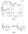
- is a plot of power with respect to time of a pulsatile application of electrosurgical energy according to an embodiment of the present disclosure;
- Fig. 4
- is a graphical representation of a linearization of energy and time plots according to an embodiment of the present disclosure;
- Fig. 5
- is a flow chart diagram of a method according to an embodiment of the present disclosure;
- Figs. 6A-C
- are plots of temperature with respect to distance from an electrode according to an embodiment of the present disclosure;
- Fig. 7
- is a flow chart diagram of a method according to an embodiment of the present disclosure;
- Fig. 8
- is a plot of reactive impedance of tissue and ablation size during application of electrosurgical energy according to one embodiment of the present disclosure; and
- Fig. 9
- is a flow chart diagram of a method according to an embodiment of the present disclosure.
- Particular embodiments of the present disclosure are described hereinbelow with reference to the accompanying drawings. In the following description, well-known functions or constructions are not described in detail to avoid obscuring the present disclosure in unnecessary detail.
- The generator according to the present disclosure can perform monopolar and bipolar electrosurgical procedures as well as microwave ablation procedures, including vessel sealing procedures. The generator may include a plurality of outputs for interfacing with various electrosurgical instruments (e.g., a monopolar active electrode, return electrode, bipolar electrosurgical forceps, footswitch, etc.). Further, the generator includes electronic circuitry configured for generating radio frequency power specifically suited for various electrosurgical modes (e.g., cutting, blending, division, etc.) and procedures (e.g., monopolar, bipolar, vessel sealing).
-
Fig. 1A is a schematic illustration of a monopolar electrosurgical system according to one embodiment of the present disclosure. The system includes anelectrosurgical instrument 2 having one or more electrodes for treating tissue of a patient P. Theinstrument 2 is a monopolar type instrument including one or more active electrodes (e.g., electrosurgical cutting probe, ablation electrode(s), etc.). In embodiments, theinstrument 2 may include a closed-loop fluid circulation mechanism coupled to a fluid circulation system that circulates a coolant fluid through one or more lumens disposed at least within a portion of the length of the active needle electrode. - Electrosurgical RF energy is supplied to the
instrument 2 by agenerator 20 via asupply line 4, which is connected to an active terminal 30 (Fig. 2 ) of thegenerator 20, allowing theinstrument 2 to coagulate, seal, ablate and/or otherwise treat tissue. The energy is returned to thegenerator 20 through areturn electrode 6 via areturn line 8 at a return terminal 32 (Fig. 2 ) of thegenerator 20. Theactive terminal 30 and thereturn terminal 32 are connectors configured to interface with plugs (not explicitly shown) of theinstrument 2 and thereturn electrode 6, which are disposed at the ends of thesupply line 4 and thereturn line 8, respectively. - The system may include a plurality of
return electrodes 6 that are arranged to minimize the chances of tissue damage by maximizing the overall contact area with the patient P. In addition, thegenerator 20 and thereturn electrode 6 may be configured for monitoring so-called "tissue-to-patient" contact to insure that sufficient contact exists therebetween to further minimize the chances of tissue damage. -
Fig. 1B is a schematic illustration of a bipolar electrosurgical system according to the present disclosure. The system includes a bipolarelectrosurgical forceps 10 having one or more electrodes for treating tissue of a patient P. Theelectrosurgical forceps 10 includes opposing jaw members having anactive electrode 14 and areturn electrode 16 disposed therein. Theactive electrode 14 and thereturn electrode 16 are connected to thegenerator 20 throughcable 18, which includes the supply andreturn lines terminals Fig. 2 ). Theelectrosurgical forceps 10 is coupled to thegenerator 20 at aconnector 21 having connections to the active and returnterminals 30 and 32 (e.g., pins) via a plug disposed at the end of thecable 18, wherein the plug includes contacts from the supply andreturn lines - The
generator 20 includes suitable input controls (e.g., buttons, activators, switches, touch screen, etc.) for controlling thegenerator 20. In addition, thegenerator 20 may include one or more display screens for providing the user with variety of output information (e.g., intensity settings, "treatment complete" indicators, etc.). The controls allow the user to adjust power of the RF energy, waveform parameters (e.g., crest factor, duty cycle, etc.), and other parameters to achieve the desired waveform suitable for a particular task (e.g., coagulating, tissue sealing, intensity setting, etc.). Theinstrument 2 may also include a plurality of input controls that may be redundant with certain input controls of thegenerator 20. Placing the input controls at theinstrument 2 allows for easier and faster modification of RF energy parameters during the surgical procedure without requiring interaction with thegenerator 20. -
Fig. 2 shows a schematic block diagram of thegenerator 20 having acontroller 24, a high voltage DC power supply 27 ("HVPS") and anRF output stage 28. TheHVPS 27 is connected to a conventional AC source (e.g., electrical wall outlet) and provides high voltage DC power to anRF output stage 28, which then converts high voltage DC power into RF energy and delivers the RF energy to theactive terminal 30. The energy is returned thereto via thereturn terminal 32. - In particular, the
RF output stage 28 generates sinusoidal waveforms of high RF energy. TheRF output stage 28 is configured to generate a plurality of waveforms having various duty cycles, peak voltages, crest factors, and other suitable parameters. Certain types of waveforms are suitable for specific electrosurgical modes. For instance, theRF output stage 28 generates a 100% duty cycle sinusoidal waveform in cut mode, which is best suited for ablating, fusing and dissecting tissue and a 1-25% duty cycle waveform in coagulation mode, which is best used for cauterizing tissue to stop bleeding. - The
generator 20 may include a plurality of connectors to accommodate various types of electrosurgical instruments (e.g.,instrument 2,electrosurgical forceps 10, etc.). Further, thegenerator 20 is configured to operate in a variety of modes such as ablation, monopolar and bipolar cutting coagulation, etc. It is envisioned that thegenerator 20 may include a switching mechanism (e.g., relays) to switch the supply of RF energy between the connectors, such that, for instance, when theinstrument 2 is connected to thegenerator 20, only the monopolar plug receives RF energy. - The
controller 24 includes amicroprocessor 25 operably connected to amemory 26, which may be volatile type memory (e.g., RAM) and/or non-volatile type memory (e.g., flash media, disk media, etc.). Themicroprocessor 25 includes an output port that is operably connected to theHVPS 27 and/orRF output stage 28 allowing themicroprocessor 25 to control the output of thegenerator 20 according to either open and/or closed control loop schemes. Those skilled in the art will appreciate that themicroprocessor 25 may be substituted by any logic processor (e.g., control circuit) adapted to perform the calculations discussed herein. - A closed loop control scheme is a feedback control loop wherein
sensor circuitry 22, which may include a plurality of sensors measuring a variety of tissue and energy properties (e.g., tissue impedance, tissue temperature, output current and/or voltage, voltage and current passing through the tissue, etc.), provides feedback to thecontroller 24. Such sensors are within the purview of those skilled in the art. Thecontroller 24 then signals theHVPS 27 and/orRF output stage 28, which then adjust DC and/or RF power supply, respectively. Thecontroller 24 also receives input signals from the input controls of thegenerator 20 or theinstrument 2. Thecontroller 24 utilizes the input signals to adjust power outputted by thegenerator 20 and/or performs other control functions thereon. - The present disclosure provides for a system and method of determining completion of an electrosurgical procedure. In particular, the method may be implemented as an algorithm (e.g., software) executable by an electrosurgical generator. Although the algorithm is discussed with respect to an ablation procedure, the algorithm may be adapted for any type of electrosurgical procedures, systems and/or methods.
- During ablation, energy is applied as an electrosurgical waveform in a pulsatile manner, e.g., in a plurality of cycles, as shown in
Fig. 3 for a predetermined period of time (e.g., procedure period) and/or until other termination criteria are met as discussed in more detail below. In particular,Fig. 3 shows aplot 100 of energy applied during ablation versus time. Energy may be delivered at any suitable frequency from about 10 kHz to about 1,000 kHz, in embodiments, from about 400 kHz to about 600 kHz. In embodiments, energy may be delieverd at microwave frequencies from about 300 MHz to about 10,000 MHz. During thefirst pulse 101, impedance at the tissue-electrode is measured to obtain a baseline impedance (BZ) as energy is applied at an initial power level (P). The energy is delivered until impedance rises above a predetermined threshold (MaxBZ) above the baseline impedance. In embodiments, the threshold may be from about 10 Ω to about 50 Ω, in embodiments, from about 20 Ω to about 30 Ω. The baseline impedance may be measured at about 10 seconds into the procedure. Once the threshold impedance is reached (e.g., baseline + threshold), the energy is turned off for a predetermined period oftime 102. The algorithm then applies energy in subsequent pulses (e.g.,pulses periods 104 and 106) until termination criteria (e.g., expiration of time) are reached. - Each of the
pulses subsequent pulses Fig. 3 , thepulse 103 is applied for a time that his shorter than the minimum on-time value, in response to which, the power of thesubsequent pulse 105 is decreased by a predetermined power increment (DecAmt). Since thepulse 105 is applied for a period of time longer than the maximum on-time value, in response to which, the power of thesubsequent pulse 107 is increased accordingly by a predetermined power increment (IncAmt). - In addition to terminating ablation after expiration of the procedure period the present disclosure provides for an algorithm for terminating ablation as a function of a predicted ablation size. The rate of growth for every ablation is different at any given time, with some ablations completing before the designated procedure duration and others requiring more time. The algorithm of the present disclosure utilizes energy and time to determine when an ablation size is no longer growing as fast as the predetermined rate. When the rate of growth of the ablation size reaches the predetermined threshold, the algorithm alerts the user of completion of ablation.
- Energy applied to tissue during a predetermined time period may be correlated with the resulting ablation size, since time and energy have a strong relationship to the rate of growth. The relationship may be defined by correlating ablation data. Although the correlation between time and energy and the growth rate is not linear or of a quadratic/cubic nature, a linearization may be applied to the data. It was observed that correlation between time and energy and size is observed after about 90 seconds from commencement of application of energy. Specifically, a saturation growth rate may be used to linearize the relationship between time/energy and size as shown in
Fig. 4 . After the transformation was applied, linear regression may be used to determine the relationship between the input parameters and ablation size. Regression may be performed on several subsets of the data using formula (I) below, which defines the relationship between ablation size and time and energy, in which a, b, and c are constants. Constants a, b, and c represent linearization slopes as shown inFig. 4 that were derived to fit the measured values, which are shown as dots, with the proposed functions.
- In formula (I), estimated size is calculated as an inverse of a sum of inverses of the measured time and the calculated energy. Once size is determined, the growth rate may be calculated using formula (II):

- The growth rate is obtained by differentiation of size and time.
- The method according to the present disclosure utilizes energy and time to determine when an ablation volume is no longer growing father than a predetermined growth rate. Once the threshold is reached, the algorithm alerts the user and/or terminates the procedure. The method determines the sizes of the ablation based on the formulas (I) and (II). If ablation energy is applied in a pulsatile manner as discussed above with respect to
Fig. 3 , pulsing generates discontinuities in the energy curve. This may result in false information to creep into growth rate calculations. To compensate for the pulsing, energy may be summed over longer periods of time, such as the length of an entire energy pulse or about 120 seconds. -
Fig. 5 shows a method for determining ablation completion based on time and energy, which are measured by thegenerator 20. Energy is summed during application of the energy pulses or a predetermined time period to compensate for the pulsing of energy. Energy may be calculated based on average power (e.g., using voltage and current measurements) and time. The algorithm is initialized and the formulas for calculating the size and growth rate are preloaded. Current size is calculated based on the preloaded formulas which are based on a statistically derived relationship between energy, time and size, as discussed above. - The current size is also saved as previous size and time is incremented by a desired interval. Current time is then compared with an initial time threshold corresponding to the point of time at which energy, time and size begin correlating. The algorithm utilizes a period of 90 seconds. In embodiments, the period may be any suitable interval selected based on a variety of tissue and energy parameters.
- Once the initial period of time has expired, the algorithm begins to calculate and compare the growth rate. In particular, the method calculates the size of the ablation volume and saves the value as the current size. The current size is then used in conjunction with the previously calculated size to determine the growth rate via differentiation. If the growth rate is below the predetermined threshold, the current size is saved as previous size and the method returns to the time incrementation step to repeat the size and growth rate calculations. If the growth rate is above the threshold, the method deems the ablation to be complete, at which point the
generator 20 may issue an alarm and/or terminate the energy supply. - In addition to time and energy, other tissue and/or energy properties may be utilized to predict ablation size and rate of growth. Temperature has also been shown to correlate well with size estimation. Temperature may be collected at the treatment site (e.g., within tissue) by one or more temperature probes disposed in the vicinity of the electrode or by sensors disposed on the electrosurgical instruments. In addition to temperature, location of the temperature sensors and/or probes is also provided to the
generator 20. Location of the temperature sensors and/or probes may be determined using various imaging techniques such as MRI, CT scan, ultrasound and the like. In embodiments, location of the probes may be estimated visually and input into thegenerator 20. - Correlation of temperature and ablation size is shown in
plots Figs. 6A-C , respectively. Plot 200 shows a temperature graph with boundary conditions applied to the temperature measurements. Boundary conditions represent the outer edges of the ablation volume, namely, normal state of the tissue unaffected by application of energy. Plot 202 shows interpolated temperature values based on measured temperature values. Plot 204 shows calculation of the ablation size using a damage integral formula (III).
- In formula (III), E is a constant derived to fit the measured values to the proposed growth function, R is an ideal gas constant, T(t) is temperature as a function of time variable, t, C(0) is initial concentration, and C(T) is concentration as a function of specific time, T. The
plots -
Fig. 7 shows a method for determining ablation completion based on time and temperature, which are measured by thegenerator 20. The algorithm is initialized and the formulas for calculating the size and growth rate are preloaded. Current size is calculated using a rate type calculation (e.g., first order rate calculation) based on the preloaded formulas which are based on the plots ofFigs 7A-C and formula (III), as discussed above. - The current size is also saved as previous size and time is incremented by a desired interval. Current time is then compared with an initial time threshold corresponding to the point of time at which temperature, time and size begin correlating. The algorithm utilizes a period of 90 seconds. In embodiments, the period may be any suitable interval selected based on a variety of tissue and energy parameters.
- Once the initial period of time has expired, the algorithm begins to calculate and compare the growth rate. In particular, the method calculates the size of the ablation volume and saves the value as the current size. The current size is then used in conjunction with the previously calculated size to determine the growth rate via differentiation. If the growth rate is below the predetermined threshold, the current size is saved as previous size and the method returns to the time incrementation step to repeat the size and growth rate calculations. If the growth rate is above the threshold, the method deems the ablation to be complete, at which point the
generator 20 may issue an alarm and/or terminate the energy supply. - In embodiments, reactive impedance may also be utilized to determine the ablation size and the growth rate thereof and utilize these values to control the energy delivery. In particular, reactive impedance also correlates with the ablation size, which may then be used to determine the growth rate of the ablation volume. As shown in
Fig. 8 , reactive (e.g., imaginary) impedance response of the tissue also tracks pulsatile nature of the ablation procedure as detailed above. More specifically,Fig. 8 shows aplot 300 of the reactive impedance having a plurality of peaks corresponding to the application of energy during on-time pulses. The peaks of the reactive impedance may be utilized as a parameter for determining completion of ablation. -
Fig. 9 shows a method for determining ablation completion based on reactive impedance, which are measured by thegenerator 20. The peaks of the reactive impedance plot are detected by filtering or using a peak detection algorithm as described in commonly-ownedU.S. Patent Application No. (203-7444 ) ##/###,### entitled "System And Method For Monitoring And Intelligent Shut-Off" andU.S. Patent Application Serial No. 12/477,245 entitled "And Imaginary Impedance Process Monitoring And Intelligent Shut-Off," the entire contents of each of which are incorporated by reference herein. - Once the algorithm is initialized, the peaks of the reactive impedance are determined. The current peak value is also saved as previous peak value and time is incremented by a desired interval. Current time is then compared with an initial time threshold corresponding to the point of time at which reactive impedance and size begin correlating. The algorithm utilizes a period of 90 seconds. In embodiments, the period may be any suitable interval selected based on a variety of tissue and energy parameters.
- Once the initial period of time has expired, the algorithm begins to calculate and compare the growth rate. In particular, the method calculates the peaks of the reactive impedance and saves the peak value as the current peak value. The current peak value is then used in conjunction with the previously calculated peak value to determine the growth rate. The growth rate is calculated as the difference in successive peaks divided by the time period between the peaks. If the growth rate is below the predetermined threshold, the current size is saved as previous size and the method returns to the time incrimination step to repeat the growth rate calculations. If the growth rate is above the threshold, the method deems the ablation to be complete, at which point the
generator 20 may issue an alarm and/or terminate the energy supply. - While several embodiments of the disclosure have been shown in the drawings and/or discussed herein, it is not intended that the disclosure be limited thereto, as it is intended that the disclosure be as broad in scope as the art will allow and that the specification be read likewise. Therefore, the above description should not be construed as limiting, but merely as exemplifications of particular embodiments. Those skilled in the art will envision other modifications within the scope and spirit of the claims appended hereto.
Claims (5)
- An electrosurgical generator, comprising:sensor circuitry configured to measure voltage and current delivered to tissue; anda controller configured to measure time of energy delivery to tissue and to calculate energy delivered to tissue, the controller further configured to estimate a size of an ablation volume as a function of energy delivered to tissue and time and to calculate a growth rate of the ablation volume based on the estimated size.
- The electrosurgical generator according to claim 1,
wherein the controller is further configured to compare the calculated growth rate to a threshold growth rate. - The electrosurgical generator according to claim 2,
wherein the controller is configured to perform an action in response to a comparison of the calculated growth rate to the threshold growth rate, the action selected from the group consisting of terminating supply of energy to tissue and issuing an alarm. - The electrosurgical generator according to claim 1,
wherein the controller is configured to calculate the growth rate based on differentiation of a plurality of estimated sizes. - The electrosurgical generator according to claim 1,
wherein the controller is configured to calculate the estimated size as an inverse of a sum of inverses of the measured time and the calculated energy.
Applications Claiming Priority (1)
| Application Number | Priority Date | Filing Date | Title |
|---|---|---|---|
| US13/050,729 US20120239024A1 (en) | 2011-03-17 | 2011-03-17 | Energy-Based Ablation Completion Algorithm |
Publications (2)
| Publication Number | Publication Date |
|---|---|
| EP2499982A1 true EP2499982A1 (en) | 2012-09-19 |
| EP2499982B1 EP2499982B1 (en) | 2015-02-25 |
Family
ID=45936634
Family Applications (1)
| Application Number | Title | Priority Date | Filing Date |
|---|---|---|---|
| EP12001841.1A Active EP2499982B1 (en) | 2011-03-17 | 2012-03-19 | Energy-based ablation completion algorithm |
Country Status (5)
| Country | Link |
|---|---|
| US (1) | US20120239024A1 (en) |
| EP (1) | EP2499982B1 (en) |
| JP (1) | JP5990388B2 (en) |
| AU (1) | AU2012201624B2 (en) |
| CA (1) | CA2771632A1 (en) |
Cited By (3)
| Publication number | Priority date | Publication date | Assignee | Title |
|---|---|---|---|---|
| CN103720511A (en) * | 2012-10-10 | 2014-04-16 | 韦伯斯特生物官能(以色列)有限公司 | Ablation power control based on contact force |
| EP2805682A1 (en) * | 2013-05-24 | 2014-11-26 | Erbe Elektromedizin GmbH | Power controlled coagulation device |
| EP2666425B1 (en) * | 2012-05-22 | 2019-05-15 | Covidien LP | Computer-implemented temperature based ablation completeness algorithm |
Families Citing this family (13)
| Publication number | Priority date | Publication date | Assignee | Title |
|---|---|---|---|---|
| US8221418B2 (en) | 2008-02-07 | 2012-07-17 | Tyco Healthcare Group Lp | Endoscopic instrument for tissue identification |
| US8251987B2 (en) | 2008-08-28 | 2012-08-28 | Vivant Medical, Inc. | Microwave antenna |
| US8246615B2 (en) | 2009-05-19 | 2012-08-21 | Vivant Medical, Inc. | Tissue impedance measurement using a secondary frequency |
| US10335230B2 (en) | 2011-03-09 | 2019-07-02 | Covidien Lp | Systems for thermal-feedback-controlled rate of fluid flow to fluid-cooled antenna assembly and methods of directing energy to tissue using same |
| JP5775751B2 (en) * | 2011-06-15 | 2015-09-09 | オリンパス株式会社 | Ultrasonic irradiation device |
| US8888771B2 (en) | 2011-07-15 | 2014-11-18 | Covidien Lp | Clip-over disposable assembly for use with hemostat-style surgical instrument and methods of manufacturing same |
| US9119648B2 (en) | 2012-01-06 | 2015-09-01 | Covidien Lp | System and method for treating tissue using an expandable antenna |
| US9364278B2 (en) | 2012-04-30 | 2016-06-14 | Covidien Lp | Limited reuse ablation needles and ablation devices for use therewith |
| US9717552B2 (en) * | 2014-05-06 | 2017-08-01 | Cosman Intruments, Llc | Electrosurgical generator |
| WO2016109437A1 (en) | 2014-12-31 | 2016-07-07 | Covidien Lp | System and method for treating copd and emphysema |
| CN111526832B (en) * | 2017-12-19 | 2023-10-10 | 直观外科手术操作公司 | Simultaneous electrosurgical sealing and cutting |
| WO2019142252A1 (en) * | 2018-01-17 | 2019-07-25 | オリンパス株式会社 | Control device and method for operating control device |
| KR20220113688A (en) * | 2019-12-07 | 2022-08-16 | 아피스 메디컬 코퍼레이션 | Devices, systems and methods for calculating the amount of energy delivered to tissue during electrosurgical treatment |
Citations (2)
| Publication number | Priority date | Publication date | Assignee | Title |
|---|---|---|---|---|
| US6575969B1 (en) * | 1995-05-04 | 2003-06-10 | Sherwood Services Ag | Cool-tip radiofrequency thermosurgery electrode system for tumor ablation |
| US6962587B2 (en) * | 2000-07-25 | 2005-11-08 | Rita Medical Systems, Inc. | Method for detecting and treating tumors using localized impedance measurement |
Family Cites Families (12)
| Publication number | Priority date | Publication date | Assignee | Title |
|---|---|---|---|---|
| WO1993008756A1 (en) * | 1991-11-08 | 1993-05-13 | Ep Technologies, Inc. | Radiofrequency ablation with phase sensitive power detection |
| US5599344A (en) * | 1995-06-06 | 1997-02-04 | Valleylab Inc. | Control apparatus for electrosurgical generator power output |
| US6228079B1 (en) * | 1997-10-06 | 2001-05-08 | Somnus Medical Technology, Inc. | Method and apparatus for power measurement in radio frequency electro-surgical generators |
| US7137980B2 (en) * | 1998-10-23 | 2006-11-21 | Sherwood Services Ag | Method and system for controlling output of RF medical generator |
| US6696844B2 (en) * | 1999-06-04 | 2004-02-24 | Engineering & Research Associates, Inc. | Apparatus and method for real time determination of materials' electrical properties |
| US7195627B2 (en) * | 2003-01-09 | 2007-03-27 | Gyrus Medical Limited | Electrosurgical generator |
| US7799021B2 (en) * | 2004-08-04 | 2010-09-21 | Kimberly-Clark Inc. | Electrosurgical treatment in conjunction with monitoring |
| US20070049915A1 (en) * | 2005-08-26 | 2007-03-01 | Dieter Haemmerich | Method and Devices for Cardiac Radiofrequency Catheter Ablation |
| CA2670969C (en) * | 2006-12-06 | 2016-01-19 | Boston Scientific Limited | Tissue ablation using pulse modulated radio frequency energy |
| US8211099B2 (en) * | 2007-01-31 | 2012-07-03 | Tyco Healthcare Group Lp | Thermal feedback systems and methods of using the same |
| WO2009065140A1 (en) * | 2007-11-16 | 2009-05-22 | St. Jude Medical, Atrial Fibrillation Division, Inc. | Device and method for real-time lesion estimation during ablation |
| US8262652B2 (en) * | 2009-01-12 | 2012-09-11 | Tyco Healthcare Group Lp | Imaginary impedance process monitoring and intelligent shut-off |
-
2011
- 2011-03-17 US US13/050,729 patent/US20120239024A1/en not_active Abandoned
-
2012
- 2012-03-19 AU AU2012201624A patent/AU2012201624B2/en not_active Ceased
- 2012-03-19 EP EP12001841.1A patent/EP2499982B1/en active Active
- 2012-03-19 JP JP2012061668A patent/JP5990388B2/en active Active
- 2012-03-19 CA CA2771632A patent/CA2771632A1/en not_active Abandoned
Patent Citations (2)
| Publication number | Priority date | Publication date | Assignee | Title |
|---|---|---|---|---|
| US6575969B1 (en) * | 1995-05-04 | 2003-06-10 | Sherwood Services Ag | Cool-tip radiofrequency thermosurgery electrode system for tumor ablation |
| US6962587B2 (en) * | 2000-07-25 | 2005-11-08 | Rita Medical Systems, Inc. | Method for detecting and treating tumors using localized impedance measurement |
Cited By (14)
| Publication number | Priority date | Publication date | Assignee | Title |
|---|---|---|---|---|
| EP2666425B1 (en) * | 2012-05-22 | 2019-05-15 | Covidien LP | Computer-implemented temperature based ablation completeness algorithm |
| CN103720511B (en) * | 2012-10-10 | 2019-01-29 | 韦伯斯特生物官能(以色列)有限公司 | Ablation power control based on contact force |
| JP2014076363A (en) * | 2012-10-10 | 2014-05-01 | Biosense Webster (Israel) Ltd | Ablation power control based on contact force |
| US11096741B2 (en) | 2012-10-10 | 2021-08-24 | Biosense Webster (Israel) Ltd. | Ablation power control based on contact force |
| CN103720511A (en) * | 2012-10-10 | 2014-04-16 | 韦伯斯特生物官能(以色列)有限公司 | Ablation power control based on contact force |
| EP3510958A1 (en) * | 2012-10-10 | 2019-07-17 | Biosense Webster (Israel) Ltd. | Ablation power control based on contact force |
| EP2719351B1 (en) * | 2012-10-10 | 2019-04-17 | Biosense Webster (Israel) Ltd. | Ablation power control based on contact force |
| JP2018153684A (en) * | 2012-10-10 | 2018-10-04 | バイオセンス・ウエブスター・(イスラエル)・リミテッドBiosense Webster (Israel), Ltd. | Ablation power control based on contact force |
| CN104173103A (en) * | 2013-05-24 | 2014-12-03 | 厄比电子医学有限责任公司 | Coagulation Device Comprising an Energy Control |
| CN104173103B (en) * | 2013-05-24 | 2018-09-14 | 厄比电子医学有限责任公司 | Coagulation devices including energy hole |
| US9962218B2 (en) | 2013-05-24 | 2018-05-08 | Erbe Elektromedizin Gmbh | Coagulation device comprising an energy control |
| KR20140138058A (en) * | 2013-05-24 | 2014-12-03 | 에에르베에 엘렉트로메디찐 게엠베하 | Coagulation device comprising an energy control |
| EP2805682A1 (en) * | 2013-05-24 | 2014-11-26 | Erbe Elektromedizin GmbH | Power controlled coagulation device |
| US11207121B2 (en) | 2013-05-24 | 2021-12-28 | Erbe Elektromedizin Gmbh | Coagulation device comprising an energy control |
Also Published As
| Publication number | Publication date |
|---|---|
| EP2499982B1 (en) | 2015-02-25 |
| AU2012201624A1 (en) | 2012-10-04 |
| JP2012192188A (en) | 2012-10-11 |
| AU2012201624B2 (en) | 2014-03-27 |
| CA2771632A1 (en) | 2012-09-17 |
| JP5990388B2 (en) | 2016-09-14 |
| US20120239024A1 (en) | 2012-09-20 |
Similar Documents
| Publication | Publication Date | Title |
|---|---|---|
| EP2499982B1 (en) | Energy-based ablation completion algorithm | |
| US10543038B2 (en) | System and method for process monitoring and intelligent shut-off | |
| EP2258293B1 (en) | Imaginary impedance process monitoring and intelligent shut-off | |
| EP2301462B1 (en) | Electrosurgical generator for controlling output in response to voltage and current phases and for sustaining microbubble formation | |
| EP2296572B1 (en) | System and method for output control of electrosurgical generator | |
| EP1862137B1 (en) | System for controlling tissue heating rate prior to cellular vaporization | |
| EP2298203B1 (en) | System for terminating treatment in impedance feedback algorithm | |
| JP5618470B2 (en) | Real-time arc control in electrosurgical generators | |
| EP2108325A1 (en) | ARC generation in a fluid medium | |
| EP2407116A1 (en) | Polarity control of electrosurgical generator | |
| EP2649956A1 (en) | Electrosurgical monopolar apparatus with arc energy vascular coagulation control | |
| EP2301464A1 (en) | Electrosurgical generator user interface | |
| CA2658197A1 (en) | Crest factor enhancement in electrosurgical generators |
Legal Events
| Date | Code | Title | Description |
|---|---|---|---|
| PUAI | Public reference made under article 153(3) epc to a published international application that has entered the european phase |
Free format text: ORIGINAL CODE: 0009012 |
|
| AK | Designated contracting states |
Kind code of ref document: A1 Designated state(s): AL AT BE BG CH CY CZ DE DK EE ES FI FR GB GR HR HU IE IS IT LI LT LU LV MC MK MT NL NO PL PT RO RS SE SI SK SM TR |
|
| AX | Request for extension of the european patent |
Extension state: BA ME |
|
| 17P | Request for examination filed |
Effective date: 20130208 |
|
| RIN1 | Information on inventor provided before grant (corrected) |
Inventor name: LADTKOW, CASEY M Inventor name: BRANNAN, JOSEPH D |
|
| RAP1 | Party data changed (applicant data changed or rights of an application transferred) |
Owner name: COVIDIEN LP |
|
| RIC1 | Information provided on ipc code assigned before grant |
Ipc: A61B 18/12 20060101AFI20140728BHEP Ipc: A61B 18/18 20060101ALI20140728BHEP Ipc: A61B 18/00 20060101ALN20140728BHEP |
|
| GRAP | Despatch of communication of intention to grant a patent |
Free format text: ORIGINAL CODE: EPIDOSNIGR1 |
|
| INTG | Intention to grant announced |
Effective date: 20140917 |
|
| GRAS | Grant fee paid |
Free format text: ORIGINAL CODE: EPIDOSNIGR3 |
|
| GRAA | (expected) grant |
Free format text: ORIGINAL CODE: 0009210 |
|
| AK | Designated contracting states |
Kind code of ref document: B1 Designated state(s): AL AT BE BG CH CY CZ DE DK EE ES FI FR GB GR HR HU IE IS IT LI LT LU LV MC MK MT NL NO PL PT RO RS SE SI SK SM TR |
|
| REG | Reference to a national code |
Ref country code: GB Ref legal event code: FG4D |
|
| REG | Reference to a national code |
Ref country code: CH Ref legal event code: EP |
|
| REG | Reference to a national code |
Ref country code: IE Ref legal event code: FG4D |
|
| REG | Reference to a national code |
Ref country code: DE Ref legal event code: R096 Ref document number: 602012005338 Country of ref document: DE Effective date: 20150409 |
|
| REG | Reference to a national code |
Ref country code: AT Ref legal event code: REF Ref document number: 711236 Country of ref document: AT Kind code of ref document: T Effective date: 20150415 |
|
| REG | Reference to a national code |
Ref country code: NL Ref legal event code: VDEP Effective date: 20150225 |
|
| REG | Reference to a national code |
Ref country code: AT Ref legal event code: MK05 Ref document number: 711236 Country of ref document: AT Kind code of ref document: T Effective date: 20150225 |
|
| REG | Reference to a national code |
Ref country code: LT Ref legal event code: MG4D |
|
| PG25 | Lapsed in a contracting state [announced via postgrant information from national office to epo] |
Ref country code: LT Free format text: LAPSE BECAUSE OF FAILURE TO SUBMIT A TRANSLATION OF THE DESCRIPTION OR TO PAY THE FEE WITHIN THE PRESCRIBED TIME-LIMIT Effective date: 20150225 Ref country code: ES Free format text: LAPSE BECAUSE OF FAILURE TO SUBMIT A TRANSLATION OF THE DESCRIPTION OR TO PAY THE FEE WITHIN THE PRESCRIBED TIME-LIMIT Effective date: 20150225 Ref country code: NO Free format text: LAPSE BECAUSE OF FAILURE TO SUBMIT A TRANSLATION OF THE DESCRIPTION OR TO PAY THE FEE WITHIN THE PRESCRIBED TIME-LIMIT Effective date: 20150525 Ref country code: FI Free format text: LAPSE BECAUSE OF FAILURE TO SUBMIT A TRANSLATION OF THE DESCRIPTION OR TO PAY THE FEE WITHIN THE PRESCRIBED TIME-LIMIT Effective date: 20150225 Ref country code: HR Free format text: LAPSE BECAUSE OF FAILURE TO SUBMIT A TRANSLATION OF THE DESCRIPTION OR TO PAY THE FEE WITHIN THE PRESCRIBED TIME-LIMIT Effective date: 20150225 Ref country code: SE Free format text: LAPSE BECAUSE OF FAILURE TO SUBMIT A TRANSLATION OF THE DESCRIPTION OR TO PAY THE FEE WITHIN THE PRESCRIBED TIME-LIMIT Effective date: 20150225 |
|
| PG25 | Lapsed in a contracting state [announced via postgrant information from national office to epo] |
Ref country code: RS Free format text: LAPSE BECAUSE OF FAILURE TO SUBMIT A TRANSLATION OF THE DESCRIPTION OR TO PAY THE FEE WITHIN THE PRESCRIBED TIME-LIMIT Effective date: 20150225 Ref country code: AT Free format text: LAPSE BECAUSE OF FAILURE TO SUBMIT A TRANSLATION OF THE DESCRIPTION OR TO PAY THE FEE WITHIN THE PRESCRIBED TIME-LIMIT Effective date: 20150225 Ref country code: LV Free format text: LAPSE BECAUSE OF FAILURE TO SUBMIT A TRANSLATION OF THE DESCRIPTION OR TO PAY THE FEE WITHIN THE PRESCRIBED TIME-LIMIT Effective date: 20150225 Ref country code: GR Free format text: LAPSE BECAUSE OF FAILURE TO SUBMIT A TRANSLATION OF THE DESCRIPTION OR TO PAY THE FEE WITHIN THE PRESCRIBED TIME-LIMIT Effective date: 20150526 Ref country code: IS Free format text: LAPSE BECAUSE OF FAILURE TO SUBMIT A TRANSLATION OF THE DESCRIPTION OR TO PAY THE FEE WITHIN THE PRESCRIBED TIME-LIMIT Effective date: 20150625 |
|
| PG25 | Lapsed in a contracting state [announced via postgrant information from national office to epo] |
Ref country code: NL Free format text: LAPSE BECAUSE OF FAILURE TO SUBMIT A TRANSLATION OF THE DESCRIPTION OR TO PAY THE FEE WITHIN THE PRESCRIBED TIME-LIMIT Effective date: 20150225 |
|
| PG25 | Lapsed in a contracting state [announced via postgrant information from national office to epo] |
Ref country code: CZ Free format text: LAPSE BECAUSE OF FAILURE TO SUBMIT A TRANSLATION OF THE DESCRIPTION OR TO PAY THE FEE WITHIN THE PRESCRIBED TIME-LIMIT Effective date: 20150225 Ref country code: RO Free format text: LAPSE BECAUSE OF FAILURE TO SUBMIT A TRANSLATION OF THE DESCRIPTION OR TO PAY THE FEE WITHIN THE PRESCRIBED TIME-LIMIT Effective date: 20150225 Ref country code: EE Free format text: LAPSE BECAUSE OF FAILURE TO SUBMIT A TRANSLATION OF THE DESCRIPTION OR TO PAY THE FEE WITHIN THE PRESCRIBED TIME-LIMIT Effective date: 20150225 Ref country code: SK Free format text: LAPSE BECAUSE OF FAILURE TO SUBMIT A TRANSLATION OF THE DESCRIPTION OR TO PAY THE FEE WITHIN THE PRESCRIBED TIME-LIMIT Effective date: 20150225 Ref country code: DK Free format text: LAPSE BECAUSE OF FAILURE TO SUBMIT A TRANSLATION OF THE DESCRIPTION OR TO PAY THE FEE WITHIN THE PRESCRIBED TIME-LIMIT Effective date: 20150225 |
|
| REG | Reference to a national code |
Ref country code: CH Ref legal event code: PL |
|
| REG | Reference to a national code |
Ref country code: DE Ref legal event code: R097 Ref document number: 602012005338 Country of ref document: DE |
|
| PG25 | Lapsed in a contracting state [announced via postgrant information from national office to epo] |
Ref country code: PL Free format text: LAPSE BECAUSE OF FAILURE TO SUBMIT A TRANSLATION OF THE DESCRIPTION OR TO PAY THE FEE WITHIN THE PRESCRIBED TIME-LIMIT Effective date: 20150225 Ref country code: MC Free format text: LAPSE BECAUSE OF FAILURE TO SUBMIT A TRANSLATION OF THE DESCRIPTION OR TO PAY THE FEE WITHIN THE PRESCRIBED TIME-LIMIT Effective date: 20150225 |
|
| PG25 | Lapsed in a contracting state [announced via postgrant information from national office to epo] |
Ref country code: IT Free format text: LAPSE BECAUSE OF FAILURE TO SUBMIT A TRANSLATION OF THE DESCRIPTION OR TO PAY THE FEE WITHIN THE PRESCRIBED TIME-LIMIT Effective date: 20150225 |
|
| PLBE | No opposition filed within time limit |
Free format text: ORIGINAL CODE: 0009261 |
|
| STAA | Information on the status of an ep patent application or granted ep patent |
Free format text: STATUS: NO OPPOSITION FILED WITHIN TIME LIMIT |
|
| PG25 | Lapsed in a contracting state [announced via postgrant information from national office to epo] |
Ref country code: LI Free format text: LAPSE BECAUSE OF NON-PAYMENT OF DUE FEES Effective date: 20150331 Ref country code: CH Free format text: LAPSE BECAUSE OF NON-PAYMENT OF DUE FEES Effective date: 20150331 |
|
| 26N | No opposition filed |
Effective date: 20151126 |
|
| REG | Reference to a national code |
Ref country code: FR Ref legal event code: PLFP Year of fee payment: 5 |
|
| PG25 | Lapsed in a contracting state [announced via postgrant information from national office to epo] |
Ref country code: SI Free format text: LAPSE BECAUSE OF FAILURE TO SUBMIT A TRANSLATION OF THE DESCRIPTION OR TO PAY THE FEE WITHIN THE PRESCRIBED TIME-LIMIT Effective date: 20150225 |
|
| PG25 | Lapsed in a contracting state [announced via postgrant information from national office to epo] |
Ref country code: BE Free format text: LAPSE BECAUSE OF FAILURE TO SUBMIT A TRANSLATION OF THE DESCRIPTION OR TO PAY THE FEE WITHIN THE PRESCRIBED TIME-LIMIT Effective date: 20150225 |
|
| PG25 | Lapsed in a contracting state [announced via postgrant information from national office to epo] |
Ref country code: MT Free format text: LAPSE BECAUSE OF FAILURE TO SUBMIT A TRANSLATION OF THE DESCRIPTION OR TO PAY THE FEE WITHIN THE PRESCRIBED TIME-LIMIT Effective date: 20150225 |
|
| REG | Reference to a national code |
Ref country code: FR Ref legal event code: PLFP Year of fee payment: 6 |
|
| PG25 | Lapsed in a contracting state [announced via postgrant information from national office to epo] |
Ref country code: HU Free format text: LAPSE BECAUSE OF FAILURE TO SUBMIT A TRANSLATION OF THE DESCRIPTION OR TO PAY THE FEE WITHIN THE PRESCRIBED TIME-LIMIT; INVALID AB INITIO Effective date: 20120319 Ref country code: BG Free format text: LAPSE BECAUSE OF FAILURE TO SUBMIT A TRANSLATION OF THE DESCRIPTION OR TO PAY THE FEE WITHIN THE PRESCRIBED TIME-LIMIT Effective date: 20150225 Ref country code: SM Free format text: LAPSE BECAUSE OF FAILURE TO SUBMIT A TRANSLATION OF THE DESCRIPTION OR TO PAY THE FEE WITHIN THE PRESCRIBED TIME-LIMIT Effective date: 20150225 |
|
| PG25 | Lapsed in a contracting state [announced via postgrant information from national office to epo] |
Ref country code: CY Free format text: LAPSE BECAUSE OF FAILURE TO SUBMIT A TRANSLATION OF THE DESCRIPTION OR TO PAY THE FEE WITHIN THE PRESCRIBED TIME-LIMIT Effective date: 20150225 |
|
| PG25 | Lapsed in a contracting state [announced via postgrant information from national office to epo] |
Ref country code: PT Free format text: LAPSE BECAUSE OF FAILURE TO SUBMIT A TRANSLATION OF THE DESCRIPTION OR TO PAY THE FEE WITHIN THE PRESCRIBED TIME-LIMIT Effective date: 20150625 |
|
| PG25 | Lapsed in a contracting state [announced via postgrant information from national office to epo] |
Ref country code: TR Free format text: LAPSE BECAUSE OF FAILURE TO SUBMIT A TRANSLATION OF THE DESCRIPTION OR TO PAY THE FEE WITHIN THE PRESCRIBED TIME-LIMIT Effective date: 20150225 |
|
| PG25 | Lapsed in a contracting state [announced via postgrant information from national office to epo] |
Ref country code: LU Free format text: LAPSE BECAUSE OF NON-PAYMENT OF DUE FEES Effective date: 20150319 |
|
| REG | Reference to a national code |
Ref country code: FR Ref legal event code: PLFP Year of fee payment: 7 |
|
| PG25 | Lapsed in a contracting state [announced via postgrant information from national office to epo] |
Ref country code: MK Free format text: LAPSE BECAUSE OF FAILURE TO SUBMIT A TRANSLATION OF THE DESCRIPTION OR TO PAY THE FEE WITHIN THE PRESCRIBED TIME-LIMIT Effective date: 20150225 |
|
| PG25 | Lapsed in a contracting state [announced via postgrant information from national office to epo] |
Ref country code: AL Free format text: LAPSE BECAUSE OF FAILURE TO SUBMIT A TRANSLATION OF THE DESCRIPTION OR TO PAY THE FEE WITHIN THE PRESCRIBED TIME-LIMIT Effective date: 20150225 |
|
| PGFP | Annual fee paid to national office [announced via postgrant information from national office to epo] |
Ref country code: GB Payment date: 20210219 Year of fee payment: 10 |
|
| PGFP | Annual fee paid to national office [announced via postgrant information from national office to epo] |
Ref country code: IE Payment date: 20220218 Year of fee payment: 11 |
|
| GBPC | Gb: european patent ceased through non-payment of renewal fee |
Effective date: 20220319 |
|
| PG25 | Lapsed in a contracting state [announced via postgrant information from national office to epo] |
Ref country code: GB Free format text: LAPSE BECAUSE OF NON-PAYMENT OF DUE FEES Effective date: 20220319 |
|
| PGFP | Annual fee paid to national office [announced via postgrant information from national office to epo] |
Ref country code: FR Payment date: 20230222 Year of fee payment: 12 |
|
| PGFP | Annual fee paid to national office [announced via postgrant information from national office to epo] |
Ref country code: DE Payment date: 20230221 Year of fee payment: 12 |
|
| REG | Reference to a national code |
Ref country code: IE Ref legal event code: MM4A |
|
| PG25 | Lapsed in a contracting state [announced via postgrant information from national office to epo] |
Ref country code: IE Free format text: LAPSE BECAUSE OF NON-PAYMENT OF DUE FEES Effective date: 20230319 |