EP2508125A1 - Noise processing device and noise processing program - Google Patents
Noise processing device and noise processing program Download PDFInfo
- Publication number
- EP2508125A1 EP2508125A1 EP09851683A EP09851683A EP2508125A1 EP 2508125 A1 EP2508125 A1 EP 2508125A1 EP 09851683 A EP09851683 A EP 09851683A EP 09851683 A EP09851683 A EP 09851683A EP 2508125 A1 EP2508125 A1 EP 2508125A1
- Authority
- EP
- European Patent Office
- Prior art keywords
- potential difference
- difference signal
- intensity
- signal
- calculating
- Prior art date
- Legal status (The legal status is an assumption and is not a legal conclusion. Google has not performed a legal analysis and makes no representation as to the accuracy of the status listed.)
- Granted
Links
Images


Classifications
-
- A—HUMAN NECESSITIES
- A61—MEDICAL OR VETERINARY SCIENCE; HYGIENE
- A61B—DIAGNOSIS; SURGERY; IDENTIFICATION
- A61B5/00—Measuring for diagnostic purposes; Identification of persons
- A61B5/02—Detecting, measuring or recording pulse, heart rate, blood pressure or blood flow; Combined pulse/heart-rate/blood pressure determination; Evaluating a cardiovascular condition not otherwise provided for, e.g. using combinations of techniques provided for in this group with electrocardiography or electroauscultation; Heart catheters for measuring blood pressure
- A61B5/024—Detecting, measuring or recording pulse rate or heart rate
- A61B5/0245—Detecting, measuring or recording pulse rate or heart rate by using sensing means generating electric signals, i.e. ECG signals
-
- A—HUMAN NECESSITIES
- A61—MEDICAL OR VETERINARY SCIENCE; HYGIENE
- A61B—DIAGNOSIS; SURGERY; IDENTIFICATION
- A61B5/00—Measuring for diagnostic purposes; Identification of persons
- A61B5/16—Devices for psychotechnics; Testing reaction times ; Devices for evaluating the psychological state
- A61B5/18—Devices for psychotechnics; Testing reaction times ; Devices for evaluating the psychological state for vehicle drivers or machine operators
-
- A—HUMAN NECESSITIES
- A61—MEDICAL OR VETERINARY SCIENCE; HYGIENE
- A61B—DIAGNOSIS; SURGERY; IDENTIFICATION
- A61B5/00—Measuring for diagnostic purposes; Identification of persons
- A61B5/68—Arrangements of detecting, measuring or recording means, e.g. sensors, in relation to patient
- A61B5/6887—Arrangements of detecting, measuring or recording means, e.g. sensors, in relation to patient mounted on external non-worn devices, e.g. non-medical devices
- A61B5/6893—Cars
-
- A—HUMAN NECESSITIES
- A61—MEDICAL OR VETERINARY SCIENCE; HYGIENE
- A61B—DIAGNOSIS; SURGERY; IDENTIFICATION
- A61B5/00—Measuring for diagnostic purposes; Identification of persons
- A61B5/72—Signal processing specially adapted for physiological signals or for diagnostic purposes
- A61B5/7203—Signal processing specially adapted for physiological signals or for diagnostic purposes for noise prevention, reduction or removal
- A61B5/7207—Signal processing specially adapted for physiological signals or for diagnostic purposes for noise prevention, reduction or removal of noise induced by motion artifacts
- A61B5/7214—Signal processing specially adapted for physiological signals or for diagnostic purposes for noise prevention, reduction or removal of noise induced by motion artifacts using signal cancellation, e.g. based on input of two identical physiological sensors spaced apart, or based on two signals derived from the same sensor, for different optical wavelengths
Abstract
Description
- The embodiments discussed herein are directed to a noise processing apparatus and a noise processing program.
- There is a detecting unit that detects the physical state of a subject by using the state of a subject's pulse or heartbeat. For example, the detecting unit arranged in a vehicle detects the physical state of a driver and thus reduces the occurrence of accidents caused by deterioration of the physical state of the driver.
- For example, the detecting unit measures a potential difference signal between two electrodes that are brought into close contact with a subject and identifies, from the measured potential difference signal, an electrocardiographic signal that indicates the subject's pulse or heartbeat. Then, the detecting unit detects drowsiness or the degree of wakefulness as the subject's physical state by using the identified electrocardiographic signal.
- For example, the electrodes that are brought into contact with the subject are arranged on, for example, a steering unit (steering wheel) or a seat surface in a vehicle. The electrodes arranged on the seat surface are brought into contact with the buttocks of the subject when the subject sits on the seat. The electrodes arranged at the steering wheel are brought into contact with the hands of the subject when the subject holds the steering wheel.
- There is a processing unit that performs a reduction process for reducing noise contained in a potential difference signal. A vehicle in which the processing unit is arranged includes an electrode that is used as the reference electric potential, an electrode arranged on the steering unit, and an electrode arranged on a seat surface. The processing unit measures a potential difference signal between the electrode that is used as the reference electric potential and the electrode arranged on the steering unit and measures a potential difference signal between the electrode that is used as the reference electric potential and the electrode arranged on the seat surface. Then, the processing unit calculates the difference between the two potential difference signals to reduce the noise contained in the potential difference signal.
- Furthermore, there is an apparatus that calculates heartbeat intervals for each heartbeat and then calculates the square mean value (root mean square of successive difference) of a standard deviation or a serial difference of the heartbeat intervals to remove irregular heartbeat intervals from the calculated heartbeat intervals.
-
- Patent Literature 1: Japanese Laid-open Patent Publication No.
2009-142576 - Patent Literature 2: Japanese Laid-open Patent Publication No.
2006-198403 - However, with the processing unit described above, there is a problem in that the noise contained in the potential difference signal is not appropriately reduced. Specifically, if a subject moves his/her body or an apparatus vibrates, the noise reduction is small compared with a case in which the subject does not move his/her body or the apparatus does not vibrate.
- Accordingly, the present invention has been conceived in light of the circumstances described above, and an object thereof is to provide a noise processing apparatus and a noise processing program that appropriately reduces noise contained in a potential difference signal.
- According to an aspect of an embodiment of the invention, a noise processing apparatus includes a first measuring unit that measures a first potential difference signal between a first electrode that is arranged at a location other than a steering unit in an apparatus and a second electrode that is used as a reference electrode. The noise processing apparatus includes a second measuring unit that measures a second potential difference signal between the second electrode and a third electrode that is arranged on the steering unit in the apparatus. The noise processing apparatus includes an intensity calculating unit that calculates, at predetermined intervals, an intensity of the first potential difference signal measured by the first measuring unit and an intensity of the second potential difference signal measured by the second measuring unit. The noise processing apparatus includes a difference calculating unit that calculates a difference between the intensity of the first potential difference signal and the intensity of the second potential difference signal, which are calculated by the intensity calculating unit at the predetermined intervals. The noise processing apparatus includes a correction unit that corrects, at the predetermined intervals, the first potential difference signal and/or the second potential difference signal by using the difference calculated by the difference calculating unit such that the difference between the intensity of the first potential difference signal and the intensity of the second potential difference signal are cancelled out. The noise processing apparatus includes a differential signal calculating unit that calculates, by using the potential difference signal corrected by the correction unit at the predetermined intervals, a differential signal indicating a difference between the first potential difference signal and the second potential difference signal. The noise processing apparatus includes an output processing unit that outputs the differential signal calculated by the differential signal calculating unit.
- According to an aspect of the noise processing apparatus disclosed in the present invention, an advantage is provided in that noise contained in a potential difference signal is appropriately reduced.
-
-
FIG. 1 is a block diagram illustrating an example configuration of a noise processing apparatus according to a first embodiment. -
FIG. 2 is a block diagram illustrating an example configuration of a noise processing apparatus according to a second embodiment. -
FIG. 3 is a schematic diagram illustrating an example of steering wheel electrodes according to the second embodiment. -
FIG. 4 is a schematic diagram illustrating an example of a lower-part seat electrode and an upper-part seat electrode arranged on a vehicle seat. -
FIG. 5 is a schematic diagram illustrating an electric potential measured by an electric potential measuring unit according to the second embodiment. -
FIG. 6A is a schematic diagram illustrating an example of a first potential difference signal according to the second embodiment. -
FIG. 6B is a schematic diagram illustrating an example of a second potential difference signal according to the second embodiment. -
FIG. 7 is a schematic diagram illustratingmathematical formula 2 used to calculate an RMS. -
FIG. 8 is a schematic diagram illustrating the correction performed by a differential signal calculating unit according to the second embodiment. -
FIG. 9A is a schematic diagram illustrating a subtraction process performed by the differential signal calculating unit according to the second embodiment. -
FIG. 9B is a schematic diagram illustrating an addition process performed by the differential signal calculating unit according to the second embodiment. -
FIG. 10 is a schematic diagram illustrating a process performed by an output processing unit according to the second embodiment. -
FIG. 11 is a schematic diagram illustrating an example of heartbeat signals contained in a differential signal. -
FIG. 12 is a flowchart illustrating the flow of a process performed by the noise processing apparatus according to the second embodiment. -
FIG. 13A is a schematic diagram illustrating an example of an advantage of the second embodiment. -
FIG. 13B is a schematic diagram illustrating an example of an advantage of the second embodiment. -
FIG. 13C is a schematic diagram illustrating an example of an advantage of the second embodiment. -
FIG. 14 is a schematic diagram illustrating the relationship between the polarity and phase of a potential difference signal. -
FIG. 15 is a block diagram illustrating an example configuration of a noise processing apparatus according to a third embodiment. -
FIG. 16 is a schematic diagram illustrating an example of a waveform of a potential difference signal stored by a waveform storing unit according to the third embodiment. -
FIG. 17 is a schematic diagram illustrating an interval associated with the waveform of the potential difference signal illustrated inFIG. 16 . -
FIG. 18 is a flowchart illustrating the flow of an interval change process performed by the RMS calculating unit according to the third embodiment. -
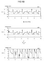
FIG. 19A is a schematic diagram illustrating an example of a potential difference signal measured when a vehicle is idling. -
FIG. 19B is a schematic diagram illustrating an example of a potential difference signal measured when a vehicle is running on a general road. -
FIG. 19C is a schematic diagram illustrating an example of a potential difference signal measured when a vehicle is running on an expressway. -
FIG. 20A is a schematic diagram illustrating an example of the RMS calculated when a vehicle is idling. -
FIG. 20B is a schematic diagram illustrating an example of the RMS calculated when a vehicle is running on a general road. -
FIG. 20C is a schematic diagram illustrating an example of the RMS calculated when a vehicle is running on an expressway. -
FIG. 21 is a block diagram illustrating an example configuration of a noise processing apparatus according to a fourth embodiment. -
FIG. 22 is a flowchart illustrating an example of the flow of a process performed by a threshold changing unit according to the fourth embodiment. -
FIG. 23A is a schematic diagram illustrating a differential signal calculating unit according to a fifth embodiment. -
FIG. 23B is a schematic diagram illustrating the differential signal calculating unit according to the fifth embodiment. -
FIG. 24 is a flowchart illustrating an example of the flow of a process performed by a noise processing apparatus according to the fifth embodiment. -
FIG. 25 is a block diagram illustrating an example of a computer that executes a noise processing program according to the second embodiment. -
- 100
- NOISE PROCESSING APPARATUS
- 101
- FIRST MEASURING UNIT
- 102
- SECOND MEASURING UNIT
- 103
- INTENSITY CALCULATING UNIT
- 104
- DIFFERENCE CALCULATING UNIT
- 105
- CORRECTION UNIT
- 106
- DIFFERENTIAL SIGNAL CALCULATING UNIT
- 107
- OUTPUT PROCESSING UNIT
- 200
- NOISE PROCESSING APPARATUS
- 201
- STEERING WHEEL ELECTRODE
- 202
- UPPER-PART SEAT ELECTRODE
- 203
- LOWER-PART SEAT ELECTRODE
- 204
- ELECTRIC POTENTIAL MEASURING UNIT
- 205
- OUTPUT UNIT
- 300
- STORING UNIT
- 301
- WAVEFORM STORING UNIT
- 400
- CONTROL UNIT
- 401
- RMS CALCULATING UNIT
- 402
- AMPLIFICATION FACTOR CALCULATING UNIT
- 403
- DIFFERENTIAL SIGNAL CALCULATING UNIT
- 404
- RMS RE-CALCULATING UNIT
- 405
- OUTPUT PROCESSING UNIT
- 406
- THRESHOLD CHANGING UNIT
- Preferred embodiments of a noise processing apparatus and a noise processing program disclosed in the present invention will be described in detail below with reference to the accompanying drawings. The present invention is not limited to the embodiments. Furthermore, the embodiments can be appropriately used in combination as long as processes do not conflict with each other.
- An example configuration of a
noise processing apparatus 100 according to a first embodiment will be described here with reference toFIG. 1. FIG. 1 is a block diagram illustrating an example configuration of a noise processing apparatus according to a first embodiment. In the example illustrated inFIG. 1 , thenoise processing apparatus 100 includes afirst measuring unit 101, asecond measuring unit 102, an intensity calculating unit 103, a difference calculating unit 104, acorrection unit 105, a differential signal calculating unit 106, and anoutput processing unit 107. - The
first measuring unit 101 measures a first potential difference signal between a first electrode that is arranged in an apparatus at a location different from a steering unit and a second electrode that is used as the reference electrode. Thesecond measuring unit 102 measures a second potential difference signal between a third electrode arranged on the steering unit of the apparatus and the second electrode. any location may be used for arranging the first electrode as long as the location is opposite the steering unit across the heart of an operator using the steering unit and is electrically brought into contact with the operator. An example of the location includes a seat surface on which the operator that uses the steering unit is sitting. - The intensity calculating unit 103 calculates, at predetermined intervals, the intensity of the first potential difference signal measured by the
first measuring unit 101 and the intensity of the second potential difference signal measured by thesecond measuring unit 102. Then, the difference calculating unit 104 calculates the difference between the intensity of the first potential difference signal and the intensity of the second potential difference signal that are calculated by the intensity calculating unit 103 at the predetermined intervals. - Then, the
correction unit 105 corrects the first potential difference signal or the second potential difference signal at the predetermined intervals by using the difference calculated by the difference calculating unit 104 in the direction in which the difference between the intensity of the first potential difference signal and the intensity of the second potential difference signal is canceled. Then, by using a potential difference signal that is corrected by thecorrection unit 105 at the predetermined intervals, the differential signal calculating unit 106 calculates a differential signal that indicates the difference between the first potential difference signal and the second potential difference signal. Then, theoutput processing unit 107 outputs the differential signal calculated by the differential signal calculating unit 106. The differential signal that is output by theoutput processing unit 107 is a potential difference signal that indicates the potential difference between the first electrode and the third electrode and becomes a potential difference signal between the electrodes that are brought into contact with two locations separated by the heart. The differential signal is also referred to as a potential difference signal. - As described above, according to the first embodiment, after correcting the intensity of the electric potential signals measured for each electrode, the differential signal is calculated, in the state in which electrodes are brought into contact with a subject at two locations separated by the heart. Therefore, according to the first embodiment, noise can be appropriately reduced from the potential difference signal between the electrodes that are brought into contact with two locations separated by the heart. Specifically, even if a subject moves his/her body or an apparatus vibrates, noise can also be reduced by an amount similar to a case in which the subject does not move his/her body or the apparatus does not vibrate.
- If a subject moves his/her body or an apparatus vibrates, the noise reduction is small compared with a case in which the subject does not move his/her body or the apparatus does not vibrate. In the following, the reason for this will be examined. If noise is reduced by calculating the difference between two potential difference signals, the noise intensities contained in potential difference signals are not the same unless the intensities of the two potential difference signals are the same, and thus the noise is not appropriately reduced even if the difference between the two potential difference signals is calculated. However, for example, there is a method for adjusting the intensities of the two potential difference signals by adjusting the area of an electrode.
- The intensity of a potential difference signal changes depending on the impedance of the electrode itself or the impedance of a contact portion between an electrode and a subject. As the impedance increases, noise contained in the potential difference signal becomes strong and is added to the potential difference signal generated from a heartbeat; therefore, the intensity of the potential difference signal also becomes strong. The impedance of the contact portion changes depending on the contact state between an electrode and a subject. If a subject moves his/her body or an apparatus vibrates, it is assumed that the contact state between an electrode arranged on the seat surface and the subject easily changes compared with the contact state between an electrode arranged on the steering unit and the subject.
- Specifically, it is assumed that the contact state between the electrode arranged on the seat surface and the subject easily changes compared with the contact state between the electrode arranged on the steering unit and the subject, and it is assumed that the impedance of the electrode arranged on the seat surface easily changes compared with the impedance of the electrode arranged on the steering unit. Furthermore, it is assumed that the noise intensities contained in each of the potential difference signals differ unless the potential difference signal from the electrode arranged on the seat surface and the potential difference signal of the electrode arranged on the steering unit change in a similar manner. Accordingly, it is assumed that, even if the difference between the two potential difference signals is calculated, the noise contained in the differential signal is not adequately canceled, and thus noise is not reduced.
- In light of the circumstances described above, according to the first embodiment, because the difference is calculated after correcting the intensities of two potential difference signals such that the intensities thereof becomes the same, the noise contained in the differential signal can appropriately be reduced. In other words, according to the first embodiment, even if the two potential difference signals change in a different manner, it is still possible to appropriately reduce the noise.
- In the following, a
noise processing apparatus 200 according to a second embodiment will be described. An example configuration of thenoise processing apparatus 200 according to the second embodiment will be described with reference toFIG. 2. FIG. 2 is a block diagram illustrating the configuration of a noise processing apparatus according to a second embodiment. In the example illustrated inFIG. 2 , thenoise processing apparatus 200 includes asteering wheel electrode 201, an upper-part seat electrode 202, a lower-part seat electrode 203, an electricpotential measuring unit 204, anoutput unit 205, astoring unit 300, and acontrol unit 400. - In the following, a case will be described in which the
steering wheel electrode 201 is arranged at a steering wheel in a vehicle as a second electrode, and the upper-part seat electrode 202 and the lower-part seat electrode 203 are on a seat surface in the vehicle as a first electrode and a third electrode, respectively, unless otherwise stated. Furthermore, a target person for whom an electric potential is measured is referred to as a subject. However, the present invention is not limited thereto as long as both thesteering wheel electrode 201 and the upper-part seat electrode 202 are arranged at a location in which they are brought into electrical contact with the subject in the time period for which an electric potential is measured. For example, if an electric potential related to an electrocardiographic wave is measured while the subject operates an apparatus, it is assumed that thesteering wheel electrode 201 and the upper-part seat electrode 202 are arranged at locations in which they are naturally brought into electrical contact with the subject via his/her motion during the operation. If thesteering wheel electrode 201 and the upper-part seat electrode 202 are arranged at such a location, the subject does not need to deliberately make an effort to measure his/her electrical potential. - Furthermore, both the
steering wheel electrode 201 and the upper-part seat electrode 202 are arranged at two locations as long as they are separated by the heart of the subject. For example, both thesteering wheel electrode 201 and the upper-part seat electrode 202 may also be arranged on a steering wheel and a backrest of a seat in a vehicle or they may also be arranged in any combination of locations. Furthermore, both the upper-part seat electrode 202 and the lower-part seat electrode 203 may also be arranged on either one of the two locations opposite the subject with the heart of the subject located therebetween. For example, both the upper-part seat electrode 202 and the lower-part seat electrode 203 may also be arranged on the backrest of the seat or may also be arranged on an arbitrary location. If an electric potential is measured when the subject stands, both the upper-part seat electrode 202 and the lower-part seat electrode 203 may be arranged at the location that, for example, the subject steps on. - The
steering wheel electrode 201 is connected to the electricpotential measuring unit 204. Furthermore, the steering wheel is also referred to as a steering unit or a steering wheel. An example structure of thesteering wheel electrode 201 will be described here with reference toFIG. 3. FIG. 3 is a schematic diagram illustrating an example of steering wheel electrodes according to the second embodiment.Reference numeral 501 illustrated inFIG. 3 denotes a steering wheel. Reference numerals "1" and "2" illustrated inFIG. 3 denotesteering wheel electrodes 201. In the example illustrated in (1) ofFIG. 3 , the twosteering wheel electrodes 201 with a uniform size are arranged in the circumferential direction of thesteering wheel 501. In the following, each of the twosteering wheel electrodes 201 are represented by a steering wheel electrode "1" and a steering wheel electrode "2". - In the following, a case will be described in which two
steering wheel electrodes 201 are arranged on thesteering wheel 501 unless otherwise stated. However, the present invention is not limited thereto. For example, a single steering wheel electrode, three or more steering wheel electrodes, or any number of steering wheel electrodes may also be arranged on thesteering wheel 501. - The
steering wheel electrodes 201 are brought into electrical contact with the subject when the subject holds thesteering wheel 501. In the example illustrated in (2) ofFIG. 3 , the steering wheel electrode "1" is brought into contact with the right hand of the subject and the steering wheel electrode "2" is brought into contact with the left hand of the subject. - In the following, the upper-
part seat electrode 202 and the lower-part seat electrode 203 will be described. Both the upper-part seat electrode 202 and the lower-part seat electrode 203 are brought into contact with the electricpotential measuring unit 204. The upper-part seat electrode 202 is arranged at a location other than the location of the electrode that is arranged on thesteering wheel 501. For example, both the upper-part seat electrode 202 and the lower-part seat electrode 203 are arranged onseat 502 in the vehicle. The lower-part seat electrode 203 is grounded to the vehicle and becomes equal to the electric potential of the vehicle. The lower-part seat electrode 203 is used as the reference electrode by thenoise processing apparatus 100. - An example of the upper-
part seat electrode 202 and the lower-part seat electrode 203 arranged on theseat 502 in the vehicle will be described here with reference toFIG. 4. FIG. 4 is a schematic diagram illustrating an example of a lower-part seat electrode and an upper-part seat electrode arranged on a vehicle seat. The symbol (1) inFIG. 4 illustrates the seat in the vehicle viewed from the top. The symbol (2)FIG. 4 is a sectional view of the seat in the vehicle. InFIG. 4 ,reference numeral 502 denotes a vehicle seat,reference numeral 503 denotes a seat member that is a member of theseat 502,reference numeral 504 denotes the lower-part seat electrode 203,reference numeral 505 denotes an insulator, andreference numerals part seat electrode 202. Furthermore, inFIG. 4 ,reference numeral 508 denotes a protection member andreference numeral 509 denotes a conductive part. - In the example illustrated in
FIG. 4 , the lower-part seat electrode 504, theinsulator 505, the upper-part seat electrodes protection member 508 are sequentially stacked on theseat member 503. Furthermore, theconductive part 509 is arranged on theprotection member 508. Theconductive part 509 is connected to the upper-part seat electrodes protection member 508 has an opening and theconductive part 509 is arranged on the inner wall of the opening. In the example illustrated inFIG. 4 , as illustrated byreference numerals FIG. 4 , the upper-part seat electrodes part seat electrodes part seat electrode 504 faces the upper-part seat electrodes insulator 505. In this case, the upper-part seat electrodes 202 are separated into two; however, they may not be separated. - In the following, a case will be described in which the two separated upper-
part seat electrodes part seat electrodes potential measuring unit 204, which will be described later, may also separately measure the electric potential of each of the upper-part seat electrodes - This section refers back to
FIG. 2 . The upper-part seat electrode 202 is brought into electrical contact with the subject when the subject sits on theseat 502. In the example illustrated inFIG. 4 , the subject sits on theseat 502 and thus the upper-part seat electrode 202 is brought into contact with the buttocks of the subject via theconductive part 509. Furthermore, in the second embodiment, a case will be described, as an example, in which the upper-part seat electrode 202 is brought into contact with the subject unless otherwise stated. Specifically, in the second embodiment, a case will be described, as an example, in which the subject sits on theseat 502. - The electric
potential measuring unit 204 is connected to thesteering wheel electrode 201, the upper-part seat electrode 202, the lower-part seat electrode 203, and thecontrol unit 400. An example of the electricpotential measuring unit 204 includes an operational amplifier. The electricpotential measuring unit 204 measures the electric potential of two locations separated by the heart of the subject. Specifically, the electricpotential measuring unit 204 measures the electric potential of thesteering wheel electrode 201 or the upper-part seat electrode 202 obtained when the electric potential of the vehicle is used as the reference electric potential. Specifically, the electricpotential measuring unit 204 measures the electric potential of the subject's hands by measuring the electric potential of the steering wheel electrode "1" and the steering wheel electrode "2", whereas it measures the electric potential of the subject's buttocks by measuring the electric potential of the upper-part seat electrode 202. - More specifically, the electric
potential measuring unit 204 measures the potential difference between the lower-part seat electrode 203 that is used as the reference electric potential and the upper-part seat electrode 202 and takes this measured potential difference to be the electric potential of the upper-part seat electrode 202. Furthermore, the electricpotential measuring unit 204 measures the potential difference between the lower-part seat electrode 203 that is used as the reference electric potential and thesteering wheel electrode 201 and takes this measured potential difference to be the electric potential of thesteering wheel electrode 201. - In the following, each of the values of the potential difference successively measured from a certain time is referred to as a potential difference signal instead of limiting a value of the potential difference obtained at a certain time. Furthermore, a potential difference signal related to the upper-
part seat electrode 202 measured by the electricpotential measuring unit 204 is referred to as a first potential difference signal. Furthermore, a potential difference signal related to thesteering wheel electrode 201 measured by the electricpotential measuring unit 204 is referred to as a second potential difference signal. - The electric potentials measured by the electric
potential measuring unit 204 will be further described with reference toFIG. 5. FIG. 5 is a schematic diagram illustrating an electric potential measured by an electric potential measuring unit according to the second embodiment. InFIG. 5 , for convenience of description, a description will be given of a case using an example in which one of the twosteering wheel electrodes 201 is brought into contact with the left hand of the subject and the other of the twosteering wheel electrodes 201 is brought into contact with the right of the subject. - The portion from the heart to the arms of the subject can be assumed to be an electrical resistance component. The hands of the subject can be assumed to be an electrical resistor capacitor (RC) parallel circuit. The portion from the heart to the buttocks of the subject can be assumed to be an electrical resistance component. Furthermore, clothes, such as trousers or a skirt, can be assumed to be an electrical RC parallel circuit. Accordingly, the schematic diagram illustrated in
FIG. 5 is an equivalent circuit including the subject. InFIG. 5 , reference numerals 510 to 512 denote an operational amplifier and correspond to the electricpotential measuring unit 204.Reference numeral 513 denotes the heart of the subject.Reference numeral 514 denotes a resistance component corresponding to the portion from theheart 513 to the right arm of the subject.Reference numeral 515 denotes an RC parallel circuit corresponding to the right arm of the subject.Reference numeral 516 denotes a resistance component corresponding to the portion from theheart 513 to the left arm of the subject.Reference numeral 517 denotes an RC parallel circuit corresponding to the left hand of the subject.Reference numeral 518 denotes a resistance component corresponding to the portion from theheart 513 to the buttocks of the subject.Reference numeral 519 denotes an RC parallel circuit corresponding to the clothes that the subject is wearing. - As illustrated in
FIG. 5 , the operational amplifier 510 includes two inputs. In the operational amplifier 510, the cardiac action potential of theheart 513 is input from the steering wheel electrode "1" via theresistance 514 and the RCparallel circuit 515 with respect to one input, whereas the electric potential of the vehicle body corresponding to the reference electric potential is input from the lower-part seat electrode 203 with respect to the other input. Then, the operational amplifier 510 amplifies the cardiac action potential obtained when the electric potential of the frame of the vehicle body is used as the reference electric potential and outputs the cardiac action potential. Specifically, in the example illustrated inFIG. 5 , the operational amplifier 510 detects the cardiac action potential from the right hand of the subject, amplifies the detected cardiac action potential, and outputs the amplified cardiac action potential. - Similarly to the operational amplifier 510, an operational amplifier 511 receives an input of the cardiac action potential of the
heart 513 from the steering wheel electrode "2" via theresistance 516 and the RCparallel circuit 517, amplifies the cardiac action potential, and outputs it. Specifically, the operational amplifier 511 detects the cardiac action potential from the left hand of the subject, amplifies it, and outputs the amplified cardiac action potential. - Similarly to the operational amplifier 510, the
operational amplifier 512 receives an input of the cardiac action potential of theheart 513 from the upper-part seat electrode 202 via theresistance 518 and the RCparallel circuit 519, amplifies the cardiac action potential, and outputs it. Specifically, theoperational amplifier 512 detects the cardiac action potential from the buttocks of the subject, amplifies it, and outputs the amplified cardiac action potential. - The reason for outputting the cardiac action potential amplified by the operational amplifiers 510 to 512 is that the cardiac action potential obtained when the electric potential of the frame of the vehicle body is used as the reference electric potential is weak. The operational amplifiers 510 to 512 amplify the cardiac action potential using a fixed amplification factor. Because the cardiac action potential detected from the buttocks of the subject is detected via the RC
parallel circuit 519, i.e., is detected via the clothes that the subject is wearing, the detected cardiac action potential is smaller than that detected from the hands of the subject. Specifically, the noise of the cardiac action potential detected from the buttocks of the subject is greater than that detected from the hands of the subject. - In the following, an example of the first potential difference signal and the second potential difference signal measured by the electric
potential measuring unit 204 will be described with reference toFIGS. 6A and 6B. FIG. 6A is a schematic diagram illustrating an example of a first potential difference signal according to the second embodiment.FIG. 6B is a schematic diagram illustrating an example of a second potential difference signal according to the second embodiment.Reference numeral 601 denotes an example of the first potential difference signal.Reference numeral 602 denotes an example of the second potential difference signal. Inreference numerals Reference numeral 611 denotes the amplitude of the first potential difference signal and is about 40 mV in the example illustrated inFIG. 6A .Reference numeral 612 denotes the amplitude of the second potential difference signal and is about 25 mV in the example illustrated inFIG. 6B . - The
output unit 205 is connected to thecontrol unit 400. Theoutput unit 205 receives information from thecontrol unit 400 and outputs the received information. The information that is output by theoutput unit 205 will not be described in detail here but will be described later together with components related to each other. - The storing
unit 300 is connected to thecontrol unit 400. The storingunit 300 stores therein data used for various processes performed by thecontrol unit 400. The storingunit 300 is a semiconductor memory device, such as a random access memory (RAM), a read only memory (ROM), a flash memory, and the like or a storage device, such as a hard disk, an optical disk, and the like. - The
control unit 400 is connected to the electricpotential measuring unit 204, theoutput unit 205, and thestoring unit 300. Thecontrol unit 400 has an internal memory for storing therein data and programs prescribing various kinds of procedures and controls various kinds of processes. Thecontrol unit 400 is an electronic circuit, such as an application specific integrated circuit (ASIC), a field programmable gate array (FPGA), a central processing unit (CPU), a micro processing unit (MPU), and the like. In the example illustrated inFIG. 2 , thecontrol unit 400 includes anRMS calculating unit 401, an amplificationfactor calculating unit 402, a differentialsignal calculating unit 403, anRMS re-calculating unit 404, and anoutput processing unit 405. The abbreviation RMS stands for "root mean square value". - For the first potential difference signal and the second potential difference signal measured by the electric
potential measuring unit 204, theRMS calculating unit 401 calculates the intensity of each potential difference signal at predetermined intervals. TheRMS calculating unit 401 is also referred to as an intensity calculating unit. For example, theRMS calculating unit 401 calculates, at 3-second intervals, the intensity of the potential difference signal by using a potential difference signal obtained between during the 3 seconds before the process time begins. - In the second embodiment, a description will be given of a case in which the
RMS calculating unit 401 calculates the intensity of the potential difference signal at 3-second intervals; however, the present invention is not limited thereto. For example, theRMS calculating unit 401 may also calculate the intensity of the potential difference signal at 4-second intervals, at 2-second intervals, or at arbitrary intervals. Furthermore, for example, theRMS calculating unit 401 may also sequentially calculate the intensity of the potential difference signal in real time. Furthermore, in the second embodiment, a description will be given of a case in which theRMS calculating unit 401 calculates the intensity of a potential difference signal by using a potential difference signal during the 2 seconds before the process time begins; however, the present invention is not limited thereto. For example, theRMS calculating unit 401 may also calculates the intensity by using the potential difference signal during the 3 seconds before the process time begins or another time period before the process time begins. - Furthermore, for example, the
RMS calculating unit 401 calculates the intensity of the potential difference signal by calculating the RMS of the potential difference signal. For example, theRMS calculating unit 401 calculates the RMS using "mathematical formula 1" or "mathematical formula 2". -

-

- A brief description of "
mathematical formula 1" and "mathematical formula 2" will be given here. The formulas indicated by "mathematical formula 1" and "mathematical formula 2" are used to calculate the RMS between the time "0" and "T". The symbol "i" represented in "mathematical formula 1" and "mathematical formula 2" indicates the value of the potential difference signal. Specifically, in "mathematical formula 1", the average value of "i" squared between the time "0" and "T" is calculated and then the square root of the calculated average value is calculated. - A description of "
mathematical formula 2" will be given with reference toFIG. 7. FIG. 7 is a schematic diagram illustratingmathematical formula 2, which is used to calculate an RMS. The symbol (1) inFIG. 7 illustrates an example of a potential difference signal measured by the electricpotential measuring unit 204. The symbol (2) inFIG. 7 illustrates an offset applied to the potential difference signal measured by the electricpotential measuring unit 204. The symbol (3) inFIG. 7 illustrates the average intensity of the potential difference signals measured by the electricpotential measuring unit 204. The symbol (4) inFIG. 7 illustrates an example of a potential difference signal from which an offset is removed from the potential difference signal measured by the electricpotential measuring unit 204. - As illustrated in (1) and (2) of
FIG. 7 , an offset is applied to the potential difference signal measured by the electricpotential measuring unit 204. Accordingly, as illustrated in (4) ofFIG. 7 , theRMS calculating unit 401 may also calculate an RMS after removing the offset from the potential difference signal. Specifically, in "mathematical formula 2", the average value of the "values of subtracting the (average value of i) from i" squared between the time "0" and "T" is calculated and then the square root of the calculated average value is calculated. The (average value of i) corresponds to the average intensity of the potential difference signals illustrated in (4) ofFIG. 7 . - For example, if the
RMS calculating unit 401 calculates the RMS of the first potential difference signals illustrated inFIG. 6A , a value of "1.49 mV" is obtained. Furthermore, if theRMS calculating unit 401 calculates the RMS of the second potential difference signals illustrated inFIG. 6B , a value of "1 mV" is obtained. - The amplification
factor calculating unit 402 calculates the difference between the intensity of the first potential difference signal and the intensity of the second potential difference signal calculated by theRMS calculating unit 401 at predetermined intervals. Specifically, every time theRMS calculating unit 401 calculates the intensity of a potential difference signal, the amplificationfactor calculating unit 402 calculates the difference between the calculated intensity of the potential difference signal. Furthermore, the amplificationfactor calculating unit 402 is also referred to as a difference calculating unit. For example, the amplificationfactor calculating unit 402 divides the RMS "1.49 mV" related to the first potential difference signal by the RMS "1 mV" related to the second potential difference signal to calculate a difference of "1.49". - By using the difference calculated by the amplification
factor calculating unit 402, the differentialsignal calculating unit 403 corrects, at predetermined intervals, the first potential difference signal and the second potential difference signal such that the intensities of the first potential difference signal and the second potential difference signal become equal. The differentialsignal calculating unit 403 is also referred to as a correction unit. For example, a description will be given of a case, as an example, in which the amplificationfactor calculating unit 402 calculates the difference by dividing the intensity of the first potential difference signal by the intensity of the second potential difference signal. In such a case, the differentialsignal calculating unit 403 corrects the second potential difference signal by using the difference "1.49" calculated by the amplificationfactor calculating unit 402. Specifically, the differentialsignal calculating unit 403 multiplies the second potential difference signal by "1.49" to determine the multiplication result of the potential difference signal to be the corrected second potential difference signal. - The correction performed by the differential
signal calculating unit 403 according to the second embodiment will be described here with reference toFIG. 8. FIG. 8 is a schematic diagram illustrating the correction performed by a differential signal calculating unit according to the second embodiment.Reference numeral 603 denotes the corrected second potential difference signal. Inreference numeral 603, the vertical axis indicates the value of the potential difference signal and the horizontal axis indicates the time axis.Reference numeral 613 denotes the amplitude of the corrected second potential difference signal and is about 40 mV in the example illustrated inFIG. 8 . - As illustrated by
reference numerals FIG. 8 , the differentialsignal calculating unit 403 multiplies the second potential difference signal before correction by "1.49" and defines the multiplication result of the potential difference signal as the corrected second potential difference signal. Accordingly, as illustrated byreference numeral 612 inFIG. 8 , in the second potential difference signal before the correction, the amplitude is about 25 mV, whereas, as illustrated byreference numeral 613 inFIG. 8 , in the corrected second potential difference signal, the amplitude is about 40 mV. In the example illustrated innumeral number 611 inFIG. 6A , the amplitude of the first potential difference signal is about 40 mV.
In other words, the intensity of the corrected second potential difference signal is the same as that of the first potential difference signal. - In the above description, a description has been given of a case in which the amplification
factor calculating unit 402 calculates the difference by dividing the intensity of the first potential difference signal by the intensity of the second potential difference signal. Furthermore, a description has been given of a case in which the differentialsignal calculating unit 403 corrects the second potential difference signal by using the difference calculated by the amplificationfactor calculating unit 402. However, the present invention is not limited thereto. Any method may be used as long as, as a result of the correction performed by the differentialsignal calculating unit 403, the intensities of the first potential difference signal and the second potential difference signal become the same. For example, the amplificationfactor calculating unit 402 may calculate the difference by dividing the intensity of the second potential difference signal by the intensity of the first potential difference signal and the differentialsignal calculating unit 403 may correct the first potential difference signal by using the difference calculated by the amplificationfactor calculating unit 402. Similarly, the differentialsignal calculating unit 403 may also correct both the first potential difference signal and the second potential difference signal such that the intensities of the first potential difference signal and the second potential difference signal become the same. - Furthermore, by using the corrected potential difference signal, the differential
signal calculating unit 403 calculates, at predetermined intervals, a differential signal indicating the difference between the first potential difference signal and the second potential difference signal. Specifically, the differentialsignal calculating unit 403 calculates the first differential signal by performing a subtraction process for subtracting the second potential difference signal from the first potential difference signal or performing a subtraction process for subtracting the first potential difference signal from the second potential difference signal. Furthermore, the differentialsignal calculating unit 403 calculates the second differential signal by performing an addition process for adding the second potential difference signal to the first potential difference signal. - The subtraction process and the addition process performed by the differential
signal calculating unit 403 according to the second embodiment will be described with reference toFIGS. 9A and9B .FIG. 9A is a schematic diagram illustrating a subtraction process performed by the differential signal calculating unit according to the second embodiment.FIG. 9B is a schematic diagram illustrating an addition process performed by the differential signal calculating unit according to the second embodiment. When the subtraction process is described with reference toFIG. 9A , a description will be given of a case, as an example, in which the second potential difference signal is subtracted from the first potential difference signal. -
Reference numeral 604 denotes an example of the first differential signal obtained as the result of the subtraction process.Reference numeral 605 denotes an example of the second differential signal obtained as the result of the addition process.Reference numeral 614 denotes the amplitude of the first differential signal obtained as the result of the subtraction process. Inreference numeral FIG. 9A .Reference numeral 615 denotes the amplitude of the second differential signal obtained as the result of the addition process and is equal to or greater than 20 mV illustrated in the example inFIG. 9B . Furthermore, the intensity of the potential difference signal that is obtained after the correction performed by the differentialsignal calculating unit 403 and that is used for the addition process or the subtraction process is about 40 mV. -
FIG. 9A will be described here. As illustrated byreference numeral FIG. 9A , if the differentialsignal calculating unit 403 performs the subtraction process, the differentialsignal calculating unit 403 subtracts the corrected second potential difference signal from, for example, the first potential difference signal. Consequently, as illustrated byreference numeral 604 inFIG. 9A , the differentialsignal calculating unit 403 calculates the first differential signal. -
FIG. 9B will be described here. As illustrated byreference numeral FIG. 9B , if the differentialsignal calculating unit 403 performs the addition process, the differentialsignal calculating unit 403 adds the corrected second potential difference signal to the first potential difference signal. Consequently, as illustrated byreference numeral 605 inFIG. 9B , the differentialsignal calculating unit 403 calculates the second differential signal. The purpose of performing the subtraction process and the addition process by the differentialsignal calculating unit 403 will be described later when an advantage of the second embodiment is described; therefore, the description thereof will be omitted here. - For the first differential signal and the second differential signal calculated by the differential
signal calculating unit 403, theRMS re-calculating unit 404 calculates the intensity of the differential signal. For example, similarly to theRMS calculating unit 401, theRMS re-calculating unit 404 calculates the intensity of the potential difference signal by calculating the RMS using "mathematical formula 1" or "mathematical formula 2". For example, theRMS re-calculating unit 404 calculates the RMS of the first differential signal indicated byreference numeral 604 illustrated inFIG. 9A and calculates the RMS of the second differential signal indicated byreference numeral 605 illustrated inFIG. 9B . In the examples illustrated inreference numeral 614 inFIG. 9A orreference numeral 615 inFIG. 9B , the amplitude of the first differential signal is smaller than that of the second differential signal. Accordingly, the value of the RMS of the first differential signal is smaller than that of the second differential signal. - In the following, a description will be given of a case, as an example, in which the
RMS re-calculating unit 404 calculates the intensity of the potential difference signal by using the same method used by theRMS calculating unit 401 unless otherwise stated; however, the present invention is not limited thereto. Specifically, theRMS re-calculating unit 404 and theRMS calculating unit 401 may also calculate the intensity of the potential difference signal by using different methods. - The
output processing unit 405 outputs, from theoutput unit 205, a differential signal that is smaller than the other intensity of the potential difference signal calculated by theRMS re-calculating unit 404. Specifically, between the two differential signals obtained as the result of the subtraction process performed by the differentialsignal calculating unit 403, theoutput processing unit 405 outputs a differential signal that is smaller than the other calculated intensity of the potential difference signal. - For example, the
output processing unit 405 outputs a differential signal to an identification apparatus that identifies the pulse or the heartbeat of the subject from the differential signal. Then, for example, the identification apparatus identifies the pulse or the heartbeat of the subject from the differential signal or measures the degree of wakefulness of the subject. - In the second embodiment, a description will be given of a case, as an example, in which the
noise processing apparatus 200 is different from the identification apparatus; however, the present invention is not limited thereto. For example, thenoise processing apparatus 200 may also be integrated with the identification apparatus. In such a case, thenoise processing apparatus 200 further identifies the pulse or the heartbeat of the subject from the differential signal or further detects the physical state of the subject by using the state of the identified pulse or heartbeat of the subject. Furthermore, thenoise processing apparatus 200 may also be a part of the identification apparatus. In such a case, theoutput processing unit 405 outputs a differential signal to another unit, from among the units included in the identification apparatus, that identifies the pulse or the heartbeat of the subject from the differential signal. - Furthermore, the differential signal that is output by the
output processing unit 405 is a potential difference signal indicating the potential difference between thesteering wheel electrode 201 and the upper-part seat electrode 202 and is a potential difference signal between the electrodes that are brought into contact with the two locations separated by the heart. - A process performed by the
output processing unit 405 according to the second embodiment will be described with reference toFIG. 10 here.FIG. 10 is a schematic diagram illustrating a process performed by an output processing unit according to the second embodiment. The symbol (1) illustrated inFIG. 10 indicates the first differential signal, the symbol (2) illustrated inFIG. 10 indicates the second differential signal, and the symbol (3) illustrated inFIG. 10 indicates the potential difference signal that is output by theoutput processing unit 405. In (1) to (3) illustrated inFIG. 10 , the vertical axis indicates the value of the electric potential and the horizontal axis indicates the time axis. - As illustrated in (1) and (2) of
FIG. 10 , theoutput processing unit 405 compares the intensity of the first differential signal with the intensity of the second differential signal. At this time, the value of the RMS of the first differential signal is smaller than that of the second differential signal. Accordingly, as illustrated in (3) ofFIG. 10 , theoutput processing unit 405 selects the first differential signal and outputs the selected first differential signal. - As described above, the differences that are used when the differential
signal calculating unit 403 performs the correction differ depending on predetermined intervals. Accordingly, the differential signals that are output by theoutput processing unit 405 are not always the same. For example, if theoutput processing unit 405 outputs the first differential signal at a certain time, theoutput processing unit 405 does not always output the first differential signal at another time; and there may be a case in which theoutput processing unit 405 outputs the second differential signal. - Furthermore, it is assumed that the two differential signals contain a heartbeat signal having the same intensity. Furthermore, although depending on the contact state of the subject and the electrode, the noise intensity contained in the potential difference signal is greater than the intensity of the heartbeat signal.
- An example of the heartbeat signal contained in the differential signal will be described here with reference to
FIG. 11. FIG. 11 is a schematic diagram illustrating an example of heartbeat signals contained in a differential signal. The differential signal illustrated inFIG. 11 is an example of the differential signal that is output by theoutput processing unit 405. InFIG. 11 , the vertical axis indicates the value of the differential signal and the horizontal axis indicates the time axis.Reference numeral 701 illustrated inFIG. 11 denotes arrows each indicating the heartbeat signal contained in the differentials signal. As illustrated by each of the arrows indicated by thereference numeral 701 inFIG. 11 , the percentage of the intensities of the heartbeat signal occupied is smaller than the noise intensity from among the intensities of the differential signal. - Accordingly, it is assumed that the difference between the intensities of the two differential signals corresponds to the difference between the noise intensities contained in the two differential signals. Specifically, even if the
output processing unit 405 outputs a differential signal by simply selecting the differential signal with the smaller intensity, theoutput processing unit 405 can outputs the differential signal containing the smaller noise intensity between the two differential signals. - In the following, the flow of a process performed by the
noise processing apparatus 200 according to the second embodiment will be described with reference toFIG. 12. FIG. 12 is a flowchart illustrating the flow of a process performed by the noise processing apparatus according to the second embodiment. In the following, a description will be given of a case, as an example, in which the amplificationfactor calculating unit 402 calculates the difference by dividing the intensity of the first potential difference signal by the intensity of the second potential difference signal. Furthermore, a description will be given of a case, as an example, in which the differentialsignal calculating unit 403 corrects the second potential difference signal by using the difference calculated by the amplificationfactor calculating unit 402. Furthermore, a description will be given of a case, as an example, in which the value of the RMS of the first differential signal is smaller than that of the second differential signal. - As illustrated in
FIG. 12 , if a potential difference signal is measured by the electric potential measuring unit 204 (Yes at Step S101), i.e., if the first potential difference signal or the second potential difference signal is measured, theRMS calculating unit 401 calculates the intensity of the potential difference signal at predetermined intervals (Step S102). For example, theRMS calculating unit 401 calculates each of the RMSs of the first potential difference signal and the second potential difference signal. - Then, the amplification
factor calculating unit 402 calculates the difference between the intensity of the first potential difference signal and the intensity of the second potential difference signal (Step S103). For example, the amplificationfactor calculating unit 402 divides the calculated RMS of the first potential difference signal by the calculated RMS of the second potential difference signal to calculate a difference of "1.49". - Then, the differential
signal calculating unit 403 corrects the second potential difference signal such that the intensity of the first potential difference signal becomes the same as that of the second potential difference signal (Step S104). For example, the differentialsignal calculating unit 403 multiplies the second potential difference signal by "1.49" and defines the multiplication result of the potential difference signal as the corrected second potential difference signal. - Then, by using the corrected potential difference signal, the differential
signal calculating unit 403 calculates, at predetermined intervals, a differential signal indicating the difference between the first potential difference signal and the second potential difference signal (Step S105). For example, by subtracting the corrected second potential difference signal from the first potential difference signal, the differentialsignal calculating unit 403 calculates the first differential signal. Furthermore, for example, by adding the corrected second potential difference signal to the first potential difference signal, the differentialsignal calculating unit 403 calculates the second differential signal. - Then, for the first differential signal and the second differential signal calculated by the differential
signal calculating unit 403, theRMS re-calculating unit 404 calculates the intensity of each of the differential signals (Step S106). For example, theRMS re-calculating unit 404 calculates the RMS as the intensity of the differential signal. - Then, the
output processing unit 405 outputs, from theoutput unit 205, the differential signal having the intensity that is smaller than that calculated by the RMS re-calculating unit 404 (Step S107). At this time, the value of the RMS of the first differential signal is smaller than that of the second differential signal and theoutput processing unit 405 outputs the first differential signal. - As described above, according to the second embodiment, the
noise processing apparatus 200 measures the first potential difference signal and the second potential difference signal. Then, thenoise processing apparatus 200 calculates, at predetermined intervals, the intensities of the first potential difference signal and the second potential difference signal. Thenoise processing apparatus 200 then calculates the difference between the intensities of the first potential difference signal and the second potential difference signal that are calculated at predetermined intervals. Then, by using the calculated difference, thenoise processing apparatus 200 corrects, at predetermined intervals, the first potential difference signal and the second potential difference signal such that the intensity of the first potential difference signal becomes the same as that of the second potential difference signal. Then, by using the corrected potential difference signal, thenoise processing apparatus 200 calculates, at predetermined intervals, a differential signal and outputs the calculated differential signal. Therefore, according to the second embodiment, noise can be appropriately reduced from the potential difference signal between electrodes that are brought into contact with two positions separated by the heart. - For example, an advantage of the second embodiment will be described here with reference to
FIGS. 13A, 13B , and13C .FIGS. 13A, 13B , and13C are schematic diagrams illustrating an example of an advantage of the second embodiment.FIG. 13A illustrates an example of the first potential difference signal or the second potential difference signal.FIG. 13B illustrates an example of a signal obtained when the correction is performed such that the intensity of the first potential difference signal and the second potential difference signal are not the same and when the second potential difference signal is simply subtracted from the first potential difference signal.FIG. 13C illustrates an example of a differential signal that is output by theoutput processing unit 405 according to the second embodiment. InFIGS. 13A to 13C , the vertical axis indicates the value of the potential difference signal or the differential signal and the horizontal axis indicates the time axis. In this case, the RMS inFIG. 13A is 186 mV, the RMS inFIG. 13B is 105 mV, and the RMS inFIG. 13C is 10.4 mV. - When comparing the RMS in
FIG. 13A with the RMS inFIG. 13B , the RMS is reduced from 186 mV to 105 mV. In contrast, when comparing the RMS inFIG. 13A with the RMS inFIG. 13C , the RMS is reduced from 186 mV to 10.4 mV. Specifically, in the second embodiment, with a focus on that fact that a change in the impedance of thesteering wheel electrode 201 is different from that of the upper-part seat electrode 202, the difference is calculated after performing the correction such that the intensities of the two potential difference signals are the same. Therefore, according to the second embodiment, when compared with a case of the correction such that the intensities of the two potential difference signals are not the same, an advantage is provided in that noise reduction increases. - Furthermore, according to the second embodiment, the
noise processing apparatus 200 calculates the first differential signal by performing the subtraction process for subtracting the second potential difference signal from the first potential difference signal or subtracting the first potential difference signal from the second potential difference signal. Furthermore, thenoise processing apparatus 200 calculates the second differential signal by performing the addition process by adding the second potential difference signal to the first potential difference signal. Then, thenoise processing apparatus 200 calculates each of the intensities of the calculated first differential signal and the second differential signal and outputs a differential signal having a smaller intensity. Therefore, according to the second embodiment, even if the phase of the first potential difference signal is different from that of the second potential difference signal, noise can be reduced. - In the following, the purpose of performing the subtraction process and the addition process by the differential
signal calculating unit 403 will be described. The electrode is sometimes brought into contact with the subject via the clothes that the subject is wearing. For example, the upper-part seat electrode 202 is brought into electrical contact with the subject via a skirt or jeans. Furthermore, thesteering wheel electrode 201 is sometimes brought into electrical contact with the subject via, as a part of the clothes, gloves, an adhesive bandage, a bandage, and the like. Static electricity is generated in the clothes due to friction between the subject and the clothes or friction between the clothes and the electrode. Furthermore, the polarity of the static electricity generated in the clothes differs depending on the clothes that the subject is wearing. If the polarity of the static electricity differs, the phase of the potential difference signal obtained from the electrode differs. - The relationship between a polarity and a phase of the potential difference signal will be described here with reference to
FIG. 14. FIG. 14 is a schematic diagram illustrating the relationship between the polarity and the phase of a potential difference signal. InFIG. 14 ,reference numeral 702 denotes an example of the potential difference signal having positive polarity.Reference numeral 703 denotes an example of the potential difference signal having negative polarity.Reference numeral 704 denotes the heartbeat signal contained in the potential difference signal. Furthermore, inreference numeral FIG. 14 , from among the intensities of the potential difference signals, a portion other than the intensity associated with the heartbeat signal is the noise intensity. - As illustrated in
FIG. 14 , the phases of the potential difference signals are opposite each other between cases in which the polarity thereof is positive and negative. Accordingly, if the phases of the two potential difference signals differ and if the difference between the two potential difference signals is calculated, the noise contained in the differential signal does not decrease at all but actually increases. For example, if the differential signal is calculated by subtracting the potential difference signal, which is calculated when the polarity of the signal is negative, from the potential difference signal, which is calculated when the polarity of the signal is positive, the noise intensity contained in the calculated differential signal is greater than the noise intensity contained in the potential difference signal. - If the phases of the two potential difference signals differ, it is assumed that noise can be reduced by calculating the sum of the two potential difference signals. Specifically, it is assumed that the noise intensity in the differential signal that is obtained by calculating the sum of the two potential difference signals is smaller than the noise intensity of the potential difference signal.
- In light of the circumstances described above, according to the second embodiment, the first differential signal and the second differential signal are calculated by performing the addition process and the subtraction process and outputs the differential signal having the intensity smaller than the other differential signal between the calculated differential signals. Accordingly, the noise can be reduced regardless of the phase of the potential difference signal.
- In a third embodiment, a description will be given of a case in which the
RMS calculating unit 401 calculates, at different predetermined intervals, the intensity of the potential difference signal in accordance with the state of the first potential difference signal or the second potential difference signal. For example, a description will be given of a case in which theRMS calculating unit 401 calculates, in accordance with the first potential difference signal or the second potential difference signal, the intensity of the potential difference signal at predetermined intervals, e.g., at 3-second intervals or at 5-second intervals. - In the third embodiment, a case will be described of using, as an example of the state of the first potential difference signal or the second potential difference signal, the intensity or the waveform of the potential difference signal. In the following, a description of components that are identical to those of the noise processing apparatus according to the second embodiment will be omitted.
- In the following, a configuration example of a
noise processing apparatus 200a according to the third embodiment will be described with reference toFIG. 15. FIG. 15 is a block diagram illustrating an example configuration of a noise processing apparatus according to a third embodiment. As illustrated inFIG. 15 , thenoise processing apparatus 200a further includes awaveform storing unit 301 in addition to the units included in thenoise processing apparatus 200 that has been described usingFIG. 2 . - The
waveform storing unit 301 stores therein an interval by associating it with the waveform of the potential difference signal. Information stored by thewaveform storing unit 301 is used by theRMS calculating unit 401. An example of the waveform of the potential difference signal stored by thewaveform storing unit 301 according to the third embodiment will be described with reference toFIG. 16. FIG. 16 is a schematic diagram illustrating an example of a waveform of a potential difference signal stored by a waveform storing unit according to the third embodiment.FIG. 16 illustrates an example of the potential difference signal measured when the subject sits down again. InFIG. 16 , the vertical axis indicates the value of the potential difference signal and the horizontal axis indicates the time axis. In the example illustrated inFIG. 16 , when the subject sits down again, the value of the potential difference signal varies locally and significantly. - The
waveform storing unit 301 stores therein intervals shorter than those obtained when the waveform of the potential difference signal does not vary locally and significantly by associating the intervals with the waveform of the potential difference signal illustrated inFIG. 16 . For example, thewaveform storing unit 301 stores therein "2 seconds" by associating it with the waveform of the potential difference signal illustrated inFIG. 16 . - The interval associated with the waveform of the potential difference signal illustrated in
FIG. 16 will be described here with reference toFIG. 17. FIG. 17 is a schematic diagram illustrating an interval associated with the waveform of the potential difference signal illustrated inFIG. 16. FIG. 17 illustrates an example of the RMS calculated from the potential difference signal illustrated inFIG. 16 . InFIG. 17 , the vertical axis indicates the value of the RMS and the horizontal axis indicates the time axis. The horizontal axis illustrated inFIG. 17 is associated with that illustrated inFIG. 16 . - If the subject sits on the seat again, the value of the potential difference signal varies locally and significantly. Accordingly, as illustrated in
FIG. 17 , if the subject sits down again, the value of the RMS also varies locally and significantly. When calculating the RMS of both a portion in which values vary locally and significantly and a portion in which values do not vary locally and significantly, the calculated value of the RMS becomes small at the portion in which the value of the potential difference signal varies locally and significantly, whereas the calculated value of the RMS becomes large at the portion in which the value of the potential difference signal does not vary locally and significantly. Accordingly, from among the potential difference signals, for the portion in which the value of the potential difference signal varies locally and significantly, the RMS is preferably calculated using a portion in which the value of the potential difference signal varies significantly without using a portion in which the value of the potential difference signal does not vary locally. Furthermore, from among the potential difference signals, for the portion in which the value of the potential difference signal does not vary locally and significantly, the RMS is preferably calculated using a portion in which the value of the potential difference signal does not vary locally and significantly without using a portion in which the value of the potential difference signal varies significantly. Because thewaveform storing unit 301 stores therein a short interval by associating it with the waveform of the potential difference signal illustrated inFIG. 16 , as will be described later, theRMS calculating unit 401 can calculate the RMS by distinguishing the portion in which the value varies locally and significantly from the portion in which the value does not vary locally and significantly. - In the following, a description will be given of a case in which the
waveform storing unit 301 stores therein "2 seconds" by associating it with a waveform of the potential difference signal illustrated inFIG. 16 ; however, the present invention is not limited thereto. For example, thewaveform storing unit 301 may also store therein a value indicating an interval shorter than 2 seconds, longer than 2 seconds, or an arbitrary value. In such a case, as a stored value associated with the waveform of the potential difference signal, it is assumed that the time intervals of the waveform of the potential difference signal will be used. In the example illustrated inFIG. 16 , the characteristic waveform, i.e., the pattern of the waveform, is detected during the one second between 29 and 30 on the horizontal axis and during the one second between 31 and 32 on the horizontal axis. Accordingly, as a value that is stored and is associated with the waveform of the potential difference signal, it is possible to store one second, which is an interval of one second between 29 and 30 and between 31 and 32, by associating the interval with the waveform. Alternatively, if all of the waveforms illustrated inFIG. 16 are detected from a series of the operations, 3 seconds between 29 and 32 may also be associated with the waveform. The local and large variation in the potential difference signal can be assumed to be the operation time performed by the subject. In this way, by using time intervals from which a pattern waveform is obtained in accordance with the pattern waveform associated with a series of the operations performed by the subject, it is possible to set an interval that is used to calculate the RMS according to the time taken for the operation by the subject. - Furthermore, in the following, a case will be described in which the
waveform storing unit 301 stores therein an interval by associating it with the waveform of the potential difference signal; however, the present invention is not limited thereto. For example, thewaveform storing unit 301 may also store therein information used for shortening or lengthening the interval by associating it with the waveform of the potential difference signal. - The
RMS calculating unit 401 according to the third embodiment calculates, at different predetermined intervals, the intensity of the potential difference signal in accordance with the state of the first potential difference signal or the second potential difference signal. Specifically, theRMS calculating unit 401 calculates, at different predetermined intervals, the intensity of the potential difference signal in accordance with the waveform or the intensity of the first potential difference signal or the second potential difference signal. - In the following, a description will be given of a case in which the operation is performed in accordance with the waveform of the first potential difference signal or the second potential difference signal. The
RMS calculating unit 401 calculates the intensity of the potential difference signal at different predetermined intervals in accordance with the pattern of the waveform of the first potential difference signal or the second potential difference signal. For example, theRMS calculating unit 401 determines whether the waveform of the first potential difference signal or the second potential difference signal matches the waveform of the potential difference signal stored in thewaveform storing unit 301. Then, if theRMS calculating unit 401 determines that they match, theRMS calculating unit 401 reads, from thewaveform storing unit 301, the information associated with the matched waveform of the potential difference signal. Then, theRMS calculating unit 401 changes the interval in accordance with the read information. - In the following, a case will be described in detail in which "5 seconds" is used as an interval. If the
RMS calculating unit 401 determines that the waveform pattern of the first potential difference signal or the second potential difference signal matches the waveform of the potential difference signal illustrated inFIG. 16 , theRMS calculating unit 401 reads "2 seconds" from thewaveform storing unit 301. Then, theRMS calculating unit 401 changes the interval from "5 seconds" to "2 seconds". Accordingly, after that, theRMS calculating unit 401 calculates, at two-second intervals, the intensity of the potential difference signal by using the potential difference signal during the 2 seconds before the process time begins. - In the following, a description will be given of a case in which the operation is performed in accordance with the intensity of the first potential difference signal or the second potential difference signal. If the intensity of the first potential difference signal or the second potential difference signal is smaller than a threshold in a predetermined time period, the
RMS calculating unit 401 calculates the intensity by using an interval longer than that used in a case in which the intensity of the first potential difference signal or the second potential difference signal is not smaller than the threshold for a predetermined period. The threshold used by theRMS calculating unit 401 is also referred to as an intensity calculating threshold. - This will be further described in detail by using a case, as an example, in which the intensity calculating threshold is "200 mV", a predetermined period is "one minute", and an interval is "5 seconds". If the
RMS calculating unit 401 obtains, as the calculation result, a value smaller than "200 mV", theRMS calculating unit 401 determines whether the value of the RMS is smaller than "200 mV" for one minute or more. Then, if theRMS calculating unit 401 determines that the value of the RMS is smaller than "200 mV" for one minute or more, theRMS calculating unit 401 changes the interval from "5 seconds" to "10 seconds". Consequently, after that, theRMS calculating unit 401 calculates, at 10-second intervals, the intensity of the potential difference signal by using the potential difference signal during the 10 seconds before the process time begins. - In the above description, a case has been described in which one minute is used as a predetermined period; however, the present invention is not limited thereto. For example, it is possible to use any time period, such as a time period shorter than one minute or a time period longer than one minute. Furthermore, in the above description, a case has been described in which the interval is changed from "5 seconds" to "10 seconds"; however, the present invention is not limited thereto. For example, the interval can be changed to an arbitrary value.
- Furthermore, for example, if the intensity of the first potential difference signal or the second potential difference signal is greater than the threshold, the
RMS calculating unit 401 calculates the intensity by using an interval shorter than that used in a case in which the intensity of the first potential difference signal and the second potential difference signal is not greater than the threshold. - This will be further described using a case, as an example, in which the intensity calculating threshold is "200 mV" and an interval is "5 seconds". The
RMS calculating unit 401 determines whether, as the calculation result, theRMS calculating unit 401 obtains a value greater than "200 mV". Then, if theRMS calculating unit 401 determines that it obtains a greater value, theRMS calculating unit 401 changes the interval from "5 seconds" to "3 seconds". Consequently, after that, theRMS calculating unit 401 calculates, at three-second intervals, the intensity of the potential difference signal by using the potential difference signal during the 3 seconds before the process time begins. - An example of the flow of the interval change process performed by the
RMS calculating unit 401 according to the third embodiment will be described here with reference toFIG. 18. FIG. 18 is a flowchart illustrating the flow of an interval change process performed by the RMS calculating unit according to the third embodiment. In the following, a case will be described in which different predetermined intervals are used in accordance with the intensity of the first potential difference signal or the second potential difference signal. In the following, a description will be given of a case in which the intensity calculating threshold is "200 mV", a predetermined period is "one minute", and an interval is "5 seconds". - If the
RMS calculating unit 401 calculates the intensity of the potential difference signal (Yes at Step S201), theRMS calculating unit 401 determines whether the calculation result is smaller than the intensity calculating threshold (Step S202). For example, theRMS calculating unit 401 determines whether the calculation result is smaller than "200 mV". If theRMS calculating unit 401 determines that the calculation result is smaller than "200 mV" (Yes at Step S202), theRMS calculating unit 401 determines whether the intensity of the potential difference signal is small for a predetermined period or more (Step S203). Then, if theRMS calculating unit 401 determines that the intensity is small for a predetermined period or more (Yes at Step S203), theRMS calculating unit 401 changes the interval to a smaller value (Step S204). For example, theRMS calculating unit 401 changes the interval from "5 seconds" to "3 seconds". Furthermore, if theRMS calculating unit 401 determines that the intensity is small for a predetermined period or more (No at Step S203), theRMS calculating unit 401 does not change the interval. - Furthermore, if the
RMS calculating unit 401 determines that the calculation result is not smaller than the intensity calculating threshold (No at Step S202), i.e., determines that the calculation result is greater than the intensity calculating threshold, theRMS calculating unit 401 changes the interval to a greater value (Step S205). For example, theRMS calculating unit 401 changes the interval from "5 seconds" to "10 seconds". - As described above, according to the third embodiment, because the
noise processing apparatus 200a calculates the intensity at different predetermined intervals in accordance with the state of the first potential difference signal or the second potential difference signal, noise contained in the potential difference signal can be appropriately reduced. For example, if a value of the RMS becomes greater, i.e., if the noise intensity contained in the potential difference signal becomes greater, the effect due to the noise can be promptly reduced by calculating the RMS after shortening the interval. Furthermore, if the value of the RMS is stable within the threshold, the number of calculations can be reduced by calculating the RMS after lengthening the interval. - In a fourth embodiment, a case will be described in which a
noise processing apparatus 200b is arranged in a vehicle and the intensity calculating threshold is changed in accordance with the speed of the vehicle. For example, as will be described below, a case will be described in which, if the speed of a vehicle is high, theRMS calculating unit 401 uses the value of "300 mV" as the intensity calculating threshold, whereas, if the speed of a vehicle is low, theRMS calculating unit 401 uses the value of "100 mV" as the intensity calculating threshold. - The purpose of changing the intensity calculating threshold in accordance with the speed will be briefly described here. It is assumed that the contact state between a subject and an electrode changes when the subject moves his/her body or an apparatus vibrates. Furthermore, the intensity of the potential difference signal changes due to the impedance of the electrode itself or the impedance of a contact portion between the electrode and the subject. As the impedance increases, the noise contained in the potential difference signal becomes strong, and thus the intensity of the potential difference signal also becomes strong. It is assumed that the impedance of the contact portion changes in accordance with the contact state between the electrode and the subject. Accordingly, the intensity of the noise contained in the potential difference signal changes due to vibrations of the vehicle or movement of the subject's body. Furthermore, it is assumed that the vibrations of the vehicle increases as the speed of the vehicle increases.
- In the following, the relationship between the speed of a vehicle and the intensity of the potential difference signal will be described with reference to
FIGS. 19A to 19C and20A to 20C .FIG. 19A is a schematic diagram illustrating an example of a potential difference signal measured when a vehicle is idling.FIG. 19B is a schematic diagram illustrating an example of a potential difference signal measured when a vehicle is running on a general road.FIG. 19C is a schematic diagram illustrating an example of a potential difference signal measured when a vehicle is running on an expressway.FIG. 20A is a schematic diagram illustrating an example of the RMS calculated when a vehicle is idling.FIG. 20B is a schematic diagram illustrating an example of the RMS calculated when a vehicle is running on a general road.FIG. 20C is a schematic diagram illustrating an example of the RMS calculated when a vehicle is running on an expressway. InFIGS. 19A to 19C , the vertical axis indicates the value of the potential difference signal and the horizontal axis indicates the time axis. InFIGS. 20A to 20C , the vertical axis indicates the value of the RMS and the horizontal axis indicates the time axis. The horizontal axes illustrated inFIGS. 19A to 19C are associated with those illustrated inFIGS. 20A to 20C . - As illustrated in
FIGS. 19A to 19C , the order of the magnitude of the amplitude of the potential difference signal is "when a vehicle is idling<when a vehicle is running on a general road<when a vehicle is running on an expressway". In other words, the amplitude of the potential difference signal obtained when a vehicle is running on an expressway is greater than that obtained when a vehicle is running on a general road, and the amplitude of the potential difference signal obtained when a vehicle is running on a general road is greater than that obtained when a vehicle is idling. Accordingly, as illustrated inFIGS. 20A to 20C , the order of the size of the RMS also becomes "idling<running on a general road<running on an expressway". In other words, the RMS obtained when a vehicle is running on an expressway is greater than that obtained when a vehicle is running on a general road and the RMS obtained when a vehicle is running on a general road is greater than that obtained when a vehicle is idling. - Accordingly, as will be described below, by changing the intensity calculating threshold in accordance with the vehicle speed, the
noise processing apparatus 200b according to the fourth embodiment can determine an interval by using an appropriate intensity calculating threshold in accordance with the vehicle speed. - An example configuration of the
noise processing apparatus 200b according to the fourth embodiment will be described here with reference toFIG. 21. FIG. 21 is a block diagram illustrating an example configuration of a noise processing apparatus according to a fourth embodiment. As illustrated inFIG. 21 , thenoise processing apparatus 200b further includes athreshold changing unit 406 in addition to the units included in thenoise processing apparatus 200 that has been described with reference toFIG. 2 . - If the intensity of the first potential difference signal or the second potential difference signal is smaller than a threshold for a predetermined period, the
RMS calculating unit 401 according to the fourth embodiment calculates the intensity by using an interval longer than that used in a case in which the intensity of the first potential difference signal or the second potential difference signal is not smaller than the threshold in a predetermined period. Furthermore, if the intensity of the first potential difference signal or the second potential difference signal is greater than the threshold, theRMS calculating unit 401 calculates the intensity by using an interval shorter than that used in a case in which the intensity of the first potential difference signal or the second potential difference signal is not greater than the threshold. The process performed by using the intensity calculating threshold in detail is the same as that in the third embodiment; therefore, a description thereof will be omitted. TheRMS calculating unit 401 performs the process by using the intensity calculating threshold controlled by thethreshold changing unit 406. - If the vehicle speed is higher than a predetermined threshold, the
threshold changing unit 406 changes the intensity calculating threshold to a value greater than that used when the vehicle speed is lower than the predetermined threshold. Furthermore, if the vehicle speed is lower than the predetermined threshold, thethreshold changing unit 406 changes the intensity calculating threshold to a value smaller than that used when the vehicle speed is higher than the predetermined threshold. In the following, as information indicating the vehicle speed, a case will be described of using three running states, i.e., "when a vehicle is idling", "when a vehicle is running on a general road", and "when a vehicle is running on an expressway". The vehicle speed increases in the order of "when a vehicle is idling", "when a vehicle is running on a general road", and "when a vehicle is running on an expressway". Specifically, the vehicle speed is the highest "when a vehicle is running on an expressway" from among the three states and the vehicle speed is the lowest "when a vehicle is idling". - Specifically, the
threshold changing unit 406 determines the running state of the vehicle. For example, thethreshold changing unit 406 acquires the vehicle speed from a memory control unit (MCU) in the vehicle or the current running position from the global positioning system (GPS). - More specifically, if the vehicle speed is, for example, 100 km or more, the
threshold changing unit 406 determines that the vehicle is running at high speed. Furthermore, if the vehicle speed is, for example, 40 km or below, thethreshold changing unit 406 determines that the vehicle is running at low speed. Furthermore, for example, if the vehicle speed is 0 km and the rotational speed of an engine is equal to or greater than a predetermined rotational speed, thethreshold changing unit 406 determines that the vehicle is idling. In the above description, a case has been described in which, if the vehicle speed is 100 km or more, thethreshold changing unit 406 determines that the vehicle is running at high speed; however, the present invention is not limited thereto. An arbitrary threshold may also be used. Furthermore, when determining whether the vehicle is idling or running on a general road, similarly, an arbitrary threshold may also be used. - Furthermore, for example, the
threshold changing unit 406 determines the running state of the vehicle by using the waveform of the potential difference signal. For example, thethreshold changing unit 406 previously stores the waveforms of the potential difference signals illustrated inFIGS. 19A to 19C by associating them with the running state of the vehicle. Specifically, thethreshold changing unit 406 stores, in a memory, the waveforms of the potential difference signals illustrated inFIGS. 19A to 19C by associating them with the state of the vehicle, such as "the vehicle is idling", "the vehicle is running on a general road", and "the vehicle is running on an expressway". Then, thethreshold changing unit 406 searches, the memory, for the waveform of the potential difference signal that matches the potential difference signal measured by the electricpotential measuring unit 204 and acquires the running state associated with the waveform of the potential difference signal from the search result. - Furthermore, if the vehicle speed is higher than the predetermined threshold, the
threshold changing unit 406 changes the intensity calculating threshold to a value greater than that used when the vehicle speed is lower than the predetermined threshold. Furthermore, if the vehicle speed is lower than the predetermined threshold, thethreshold changing unit 406 changes the intensity calculating threshold to a value smaller than that used when the vehicle speed is higher than the predetermined threshold. In the following, a case will be described in which the intensity calculating threshold obtained when a vehicle is running on a general road is "200 mV". - If the vehicle is idling, the
threshold changing unit 406 changes the intensity calculating threshold that is smaller than that used when the vehicle is running on a general road. For example, thethreshold changing unit 406 changes the intensity calculating threshold to "100 mV" that is smaller than "200 mV". Furthermore, if the vehicle is running on a general road, thethreshold changing unit 406 changes the intensity calculating threshold to "200 mV". Furthermore, if the vehicle is running on an expressway, thethreshold changing unit 406 changes the intensity calculating threshold greater than that used when the vehicle is running on a general road. For example, thethreshold changing unit 406 changes the intensity calculating threshold to "300 mV" that is greater than "200 mV". - In the above description, a case has been described in which the
threshold changing unit 406 uses "100 mV", "200 mV", and "300 mV" as the intensity calculating threshold for the states of the vehicle, i.e., "when a vehicle is idling", "when a vehicle is running on a general road", and "when a vehicle is running on an expressway", respectively; however, the present invention is not limited thereto. An arbitrary value may also be used. - Furthermore, in the above description, a case has been described in which the
threshold changing unit 406 uses three states of the vehicle, i.e., "idling", "running on a general road", and "running on an expressway"; however, the present invention is not limited thereto. For example, thethreshold changing unit 406 may also use the actual running speed of the vehicle or arbitrary information. Furthermore, for example, in addition to the states of "idling", "running on a general road", and "running on an expressway", thethreshold changing unit 406 may also use another running state and may also not use some state from among the states of "idling", "running on a general road", and "running on an expressway". - In the following, the flow of the process performed by the
threshold changing unit 406 will be described with reference toFIG. 22. FIG. 22 is a flowchart illustrating an example of the flow of a process performed by a threshold changing unit according to the fourth embodiment. InFIG. 22 , a description will be given of a case of using, as information indicating the vehicle speed, three running states, i.e., "idling", "running on a general road", and "running on an expressway". - As illustrated in
FIG. 22 , if thethreshold changing unit 406 starts the process (Yes at Step S301), thethreshold changing unit 406 determines the state of the vehicle (Step S302). Specifically, by using the vehicle speed or the waveform of the potential difference signal, thethreshold changing unit 406 determines the state of the vehicle from among the states, i.e., "idling", "running on a general road", or "running on an expressway". - If the
threshold changing unit 406 determines that the vehicle is idling (Yes at Step S303), thethreshold changing unit 406 changes the intensity calculating threshold to a threshold smaller than that used when the vehicle is running on a general road (Step S304). For example, thethreshold changing unit 406 changes the intensity calculating threshold to "100 mV" that is smaller than "200 mV". Furthermore, if thethreshold changing unit 406 determines that the vehicle is running on a general road (No at Step S303 and Yes at Step S305), thethreshold changing unit 406 changes the intensity calculating threshold to a threshold smaller than that used when the vehicle is running on an expressway (Step S306). For example, thethreshold changing unit 406 changes the intensity calculating threshold to "200 mV" that is smaller than "300 mV". Furthermore, if thethreshold changing unit 406 determines that the vehicle is running on an expressway (No at Step S303, No at Step S305, and Yes at Step S307), thethreshold changing unit 406 changes the intensity calculating threshold to the threshold greater than that used when the vehicle is running on a general road (Step S308). For example, thethreshold changing unit 406 changes the intensity calculating threshold to "300 mV" that is greater than "200 mV". Furthermore, if thethreshold changing unit 406 determines that the state is neither of the states, i.e., "idling", "running on a general road", and "running on an expressway" (No at Step S303, No at Step S305, and No at Step S307), thethreshold changing unit 406 does not change the intensity calculating threshold. - As described above, in the fourth embodiment, the
noise processing apparatus 200b is arranged in a vehicle. Furthermore, if the intensity of the first potential difference signal or the second potential difference signal is smaller than the threshold for a predetermined period, thenoise processing apparatus 200b calculates the intensity by using an interval longer than that used in a case in which the intensity is not small in a predetermined period. Furthermore, if the intensity of the first potential difference signal or the second potential difference signal is greater than the threshold, thenoise processing apparatus 200b calculates the intensity by using an interval smaller than that used when the intensity is not greater than the threshold. Furthermore, if the vehicle speed is higher than the predetermined threshold, thenoise processing apparatus 200b changes the intensity calculating threshold, used by the intensity calculating unit, to a value greater than that used in a case in which the vehicle speed is lower than the predetermined threshold. Furthermore, if the vehicle speed is lower than the predetermined threshold, thenoise processing apparatus 200b changes the intensity calculating threshold to a value smaller than that used when the vehicle speed is higher than the predetermined threshold. Accordingly, the interval can be determined by using the intensity calculating threshold suitable for the running speed of the vehicle. - Furthermore, for example, by using the difference calculated by using a potential difference signal that is acquired after acquiring a target potential difference signal to be corrected, the differential
signal calculating unit 403 may also correct the first potential difference signal or the second potential difference signal obtained at the time of acquisition. Specifically, by using the difference between an interval between the starting point and the end point, the differentialsignal calculating unit 403 may also correct the first potential difference signal or the second potential difference signal obtained at the process time. Accordingly, in a fifth embodiment, a description will be given of a case in which, by using the difference calculated by using the potential difference signal that is acquired after the target potential difference signal is acquired, the first potential difference signal or the second potential difference signal is corrected. - In the following, the differential
signal calculating unit 403 according to the fifth embodiment will be described with reference toFIGS. 23A and 23B. FIGS. 23A and 23B are schematic diagrams each illustrating a differential signal calculating unit according to a fifth embodiment.FIGS. 23A and 23B illusrate an example of the potential difference signal. InFIGS. 23A and 23B , the vertical axes indicate the value of the potential difference signal and the horizontal axes indicate the time axis. In the following, a case will be described in a case in which the interval is "2 seconds" and the potential difference signal obtained at 4 seconds is corrected. -
Reference numerals FIGS. 23A and 23B denotes the range of the potential difference signals used by theRMS calculating unit 401. In this case, an interval, during which 4 seconds corresponding to the correction time is located between the starting point and the end point of the interval, corresponds to, for example, the interval during which 4 seconds is located between the starting point and the end point, as illustrated byreference numeral 706 inFIG. 23B . Furthermore, in the example illustrated inFIG. 23B , the starting point of the interval corresponds to 5 seconds and the end point of the interval corresponds to 3 seconds. - In the following, the purpose of using the difference calculated by using the potential difference signal that is acquired after the acquisition time will be briefly described. It is assumed that, when compared a case in which the difference related to the signals obtained 2 seconds before the correction starts is used with a case in which the difference related to the signals obtained for 2 seconds for which the correction is performed is used, the calculation result of the signal intensity differs depending on a change in noise. In the example illustrated in
FIG. 23A , the peak is at 4 seconds. When correcting the peak located at 4 seconds, it is assumed that the difference related to the range including the entire peak located at 4 seconds accurately indicates the intensity difference at the peak located at 4 seconds when compared with the difference related to the range that does not include the entire peak located at 4 seconds. Accordingly, the differentialsignal calculating unit 403 corrects the potential difference signal by using the difference related to an interval during which the correction time is located between the starting and end points. - A noise processing apparatus 200c according to the fifth embodiment will be described here. In the following, a description will be given of a case in which the
RMS calculating unit 401 calculates the intensity of the potential difference signal in real time by using the potential difference signal during the 2 seconds before the process time begins. In the following, a description will be given of a case in which theRMS calculating unit 401 performs the calculation in real time; however, the present invention is not limited thereto. For example, theRMS calculating unit 401 may also perform the calculation at one-second intervals by using "2 seconds" as the interval. Specifically, theRMS calculating unit 401 may also calculate, at one-second intervals, the potential difference signal obtained from the process time to 2 seconds before the calculation. In a case of the second embodiment, the differentialsignal calculating unit 403 corrects the potential difference signal obtained at 4 seconds by using the difference related to the potential difference signals between 2 seconds and 4 seconds. - At this time, as illustrated by
reference numeral 705 inFIG. 23A , the amplificationfactor calculating unit 402 calculates, at 4 seconds, the difference between the potential difference signals obtained between 2 seconds and 4 seconds. Furthermore, as illustrated byreference numeral 706 inFIG. 23B , the amplificationfactor calculating unit 402 calculates, at 5 seconds, the difference between the potential difference signals obtained between 3 seconds and 5 seconds. - The differential
signal calculating unit 403 corrects the first potential difference signal or the second potential difference signal at the time of acquisition by using the difference calculated using a potential difference signal that is acquired after the acquisition. For example, the differentialsignal calculating unit 403 corrects, at 5 seconds, the potential difference signal obtained between 4 seconds by using the difference between the potential difference signals obtained between 3 seconds and 5 seconds. Specifically, the potential difference signal is corrected by using the difference related to the interval during which a point of 4 seconds is located between the starting and end points. In such a case, because the potential difference signal obtained at 4 seconds is corrected by using the difference calculated at 5 seconds, theoutput processing unit 405 outputs the potential difference signal with a time lag of 1 second. - As described above, according to the fifth embodiment, because the differential
signal calculating unit 403 performs the correction by using the difference related to an interval in which the acquisition time is located between the starting and end points, noise can be appropriately reduced. - A noise processing apparatus 200d may also calculate differential signals at multiple intervals including the acquisition time of the potential difference signal to be corrected and output a differential signal that contains the lowest noise. Accordingly, in a sixth embodiment, a case will be described with reference to
FIG. 24 , in which the noise processing apparatus 200d calculates differential signals at multiple intervals and outputs a differential signal containing the lowest noise.FIG. 24 is a flowchart illustrating an example of the flow of a process performed by the noise processing apparatus 200d according to the fifth embodiment. In the following, a description will be given of a case in which the correction is performed on the potential difference signal obtained at 4 seconds. - As illustrated in
FIG. 24 , in the sixth embodiment, if the potential difference signal is measured (Yes at Step S401), theRMS calculating unit 401 calculates, at multiple intervals containing the acquisition time of the potential difference signal to be corrected, the intensities of the potential difference signals by using the potential difference signals contained in the intervals (Step S402). For example, theRMS calculating unit 401 calculates the intensities of the potential difference signals at multiple different intervals, such as from 2 seconds to 4 seconds, from 3 seconds to 5 seconds, from 4 seconds to 6 seconds, from 2 seconds to 5 seconds, and from 3 seconds to 6 seconds. Furthermore, theRMS calculating unit 401 may also use different intervals or may not use the different intervals. - Then, the amplification
factor calculating unit 402 calculates the differences at multiple intervals containing the acquisition time of the potential difference signal to be corrected by using the intensities of the potential difference signals calculated by the RMS calculating unit 401 (Step S403). For example, for the intervals, such as from 2 seconds to 4 seconds, from 3 seconds to 5 seconds, from 4 seconds to 6 seconds, from 2 seconds to 5 seconds, and from 3 seconds to 6 seconds, the amplificationfactor calculating unit 402 calculates the differences of "1.49", "1.3", "1.9", "1.4", and "1.8". - Then, for the differences calculated by the amplification
factor calculating unit 402, the differentialsignal calculating unit 403 corrects the potential difference signals obtained at the acquisition time of the potential difference signal to be corrected (Step S404). For example, for the differences of "1.49", "1.3", "1.9", "1.4", and "1.8", the differentialsignal calculating unit 403 corrects the potential difference signals. Specifically, for the potential difference signal obtained at 4 seconds, the differentialsignal calculating unit 403 corrects the potential difference signal by using the difference of "1.49" and corrects the potential difference signal by using the difference of "1.3". Furthermore, the differentialsignal calculating unit 403 also corrects the potential difference signal for the differences of "1.9", "1.4", and "1.8". - Then, for the corrected potential difference signals obtained after the acquisition of the potential difference signals to be corrected, the differential
signal calculating unit 403 calculates, for the differences, the first differential signals and the second differential signals (Step S405). For example, for the potential difference signal obtained at 4 seconds, the differentialsignal calculating unit 403 calculates the first differential signal and the second differential signal by using the potential difference signal corrected using the difference of "1.49". Furthermore, similarly, for the differences of "1.3", "1.9", "1.4", and "1.8", the differentialsignal calculating unit 403 also calculates the first differential signals and the second differential signals. - Then, for each of the first differential signals and the second differential signals calculated by the differential
signal calculating unit 403 for each difference, theRMS re-calculating unit 404 calculates each of the intensities of the differential signals (Step S406). For example, for the first differential signal and the second differential signal associated with the difference of "1.49", theRMS re-calculating unit 404 calculates each of the intensities of the differential signals. Furthermore, similarly, for the differences of "1.3", "1.9", "1.4", and "1.8", theRMS re-calculating unit 404 calculates each of the intensities of the first differential signals and the second differential signals. - Then, from among the first differential signals and the second differential signals calculated for the differences, the
output processing unit 405 outputs a differential signal having the smallest intensity (Step S407). Specifically, from among the intensities calculated by theRMS re-calculating unit 404, theoutput processing unit 405 specifies the smallest intensity and outputs the differential signal associated with the specified intensity. - As described above, according to the sixth embodiment, the noise processing apparatus 200d calculates the differences at multiple intervals that contains the correction time and uses the best difference for the noise reduction from among the calculated differences; therefore, it is possible to precisely reduce the noise.
- In the above explanation, a description has been given of the embodiments according to the present invention; however, the embodiments are not limited thereto and can be implemented with various kinds of embodiments other than the embodiments described above. Therefore, another embodiment will be described below.
- For example, in the embodiments described above, a description has been given of a case in which the
output processing unit 405 simply selects the potential difference signal with the smaller intensity; however, the present invention is not limited thereto. For example, theoutput processing unit 405 may also calculate each of the ratios of the heartbeat signal to each of the two potential difference signals and may outputs the calculated potential difference signal having the larger heart beat ratio. - Furthermore, of the processes described in the embodiments, the whole or a part of the processes that are mentioned as being automatically performed can be manually performed or the whole or a part of the processes that are mentioned as being manually performed can be automatically performed using known methods. For example, in the example illustrated in
FIG. 22 , a subject may also input the state of the vehicle. In such a case, the noise processing apparatus performs the process by using the state of the vehicle that is input by the subject. Furthermore, the flow of the processes, the control procedures, the specific names, and the information (FIGS. 1 to 24 ) containing various kinds of data or parameters indicated in the above specification and drawings can be arbitrarily changed unless otherwise noted. - The components of each unit illustrated in the drawings are only for conceptually illustrating the functions thereof and are not necessarily physically configured as illustrated in the drawings. In other words, the specific shape of a separate or integrated unit is not limited to the drawings; however, all or part of the unit can be configured by functionally or physically separating or integrating any of the units depending on various loads or use conditions. For example, in the example illustrated in
FIG. 2 , thesteering wheel electrode 201 or the upper-part seat electrode 202 may also be used as an external unit of the noise processing apparatus and be connected via a network, such as a wireless local area network (LAN), such that they cooperate with each other. - The various processes described in the above embodiments can be implemented by programs prepared in advance and executed by a computer such as a personal computer or a workstation. Accordingly, in the following, a computer that executes a noise processing program having the same function performed by the apparatus in the above embodiments will be described, as an example, with reference to
FIG. 25. FIG. 25 is a block diagram illustrating an example of a computer that executes a noise processing program according to the second embodiment. - As illustrated in
FIG. 20 , acomputer 3000 according to the second embodiment includes an input/output interface 3001, acommunication unit 3006, aCPU 3010, and aROM 3011. Furthermore, thecomputer 3000 also includes a hard disk drive (HDD) 3012 and a random access memory (RAM) 3013. Each of the units included in thecomputer 3000 is connected via a bus 3009. Furthermore, thecomputer 3000 is connected to an electricpotential measuring apparatus 4001 via the input/output interface 3001. The electricpotential measuring apparatus 4001 corresponds to the electricpotential measuring unit 204. - The
ROM 3011 stores therein, in advance, a control program exhibiting the same function as theRMS calculating unit 401, the amplificationfactor calculating unit 402, the differentialsignal calculating unit 403, theRMS re-calculating unit 404, and theoutput processing unit 405 described in the second embodiment. Specifically, as illustrated inFIG. 25 , theROM 3011 stores therein, in advance, anRMS calculating program 3011a, an amplificationfactor calculating program 3011b, adifference calculating program 3011c, anRMS re-calculating program 3011d, and anoutput processing program 3011e. Theseprograms 3011a to 3011e may also be integrated or separated in the same manner as the components of thenoise processing apparatus 200 illustrated inFIG. 2 . - The
CPU 3010 reads theseprograms 3011a to 3011e from theROM 3011 and executes them. Accordingly, as illustrated inFIG. 25 , theprograms 3011a to 3011c function as anRMS calculating process 3010a, an amplificationfactor calculating process 3010b, and adifference calculating process 3010c, respectively. Furthermore, theprograms 3011d to 3011e function as anRMS re-calculating unit 3010d and anoutput processing process 3010e, respectively. Theprocesses 3010a to 3010e correspond to theRMS calculating unit 401, the amplificationfactor calculating unit 402, the differentialsignal calculating unit 403, theRMS re-calculating unit 404, and theoutput processing unit 405, respectively, illustrated inFIG. 2 . - Then, the
CPU 3010 executes the noise processing program by using data stored in theRAM 3013. For example, theCPU 3010 uses first potentialdifference signal data 3013a, second potentialdifference signal data 3013b, potential differencesignal intensity data 3013c of a potential difference signal,difference data 3013d, and firstdifferential signal data 3013e. Furthermore, theCPU 3010 uses seconddifferential signal data 3013f. - The noise processing program described in the embodiments can be distributed via a network, such as the Internet. Furthermore, the noise processing program may also be stored in a computer-readable recording medium, such as a hard disk, a flexible disk (FD), a CD-ROM, an MO, and a DVD and be implemented by the computer reading it from the recording medium.
Claims (12)
- A noise processing apparatus comprising:a first measuring unit that measures a first potential difference signal between a first electrode that is arranged at a location other than a steering unit in an apparatus and a second electrode that is used as a reference electrode;a second measuring unit that measures a second potential difference signal between the second electrode and a third electrode that is arranged on the steering unit in the apparatus;an intensity calculating unit that calculates, at predetermined intervals, an intensity of the first potential difference signal measured by the first measuring unit and an intensity of the second potential difference signal measured by the second measuring unit;a difference calculating unit that calculates a difference between the intensity of the first potential difference signal and the intensity of the second potential difference signal, which are calculated by the intensity calculating unit at the predetermined intervals;a correction unit that corrects, at the predetermined intervals, the first potential difference signal and/or the second potential difference signal by using the difference calculated by the difference calculating unit such that the difference between the intensity of the first potential difference signal and the intensity of the second potential difference signal are cancelled out;a differential signal calculating unit that calculates, by using the potential difference signal corrected by the correction unit at the predetermined intervals, a differential signal indicating a difference between the first potential difference signal and the second potential difference signal; andan output processing unit that outputs the differential signal calculated by the differential signal calculating unit.
- The noise processing apparatus according to claim 1, wherein
the differential signal calculating unit calculates a first differential signal by performing a subtraction process for subtracting the second potential difference signal from the first potential difference signal or by performing a subtraction process for subtracting the first potential difference signal from the second potential difference signal, and calculates a second differential signal by performing an addition process for adding the first potential difference signal to the second potential difference signal, and
the output processing unit calculates an intensity of the first differential signal and an intensity of the second differential signal, which are calculated by the differential signal calculating unit, and outputs whichever of the differential signals has a lower calculated intensity than the other differential signal. - The noise processing apparatus according to claim 2, wherein the intensity calculating unit calculates the intensity at different predetermined intervals in accordance with the state of the first potential difference signal and/or the second potential difference signal.
- The noise processing apparatus according to claim 3, wherein
the noise processing apparatus is arranged in a vehicle,
when the intensity of the first potential difference signal and/or the second potential difference signal is lower than a threshold for a predetermined period, the intensity calculating unit calculates the intensity by using an interval that is longer than an interval used in a case in which the intensity of the first potential difference signal and/or the second potential difference signal is not lower than the threshold for a predetermined period, when the intensity of the first potential difference signal and/or the second potential difference signal is greater than the threshold, the intensity calculating unit calculates the intensity by using an interval that is shorter than an interval used in a case in which the intensity of the first potential difference signal and/or the second potential difference signal is not greater than the threshold, and
further comprising a threshold changing unit that changes, when the speed of the vehicle is higher than a predetermined threshold, an intensity calculating threshold, which is a threshold used by the intensity calculating unit, to a value greater than a value used when the speed of the vehicle is lower than the predetermined threshold and that changes, when the speed of the vehicle is lower than the predetermined threshold, the intensity calculating threshold to a value smaller than a value used when the speed of the vehicle is higher than the predetermined threshold. - The noise processing apparatus according to claim 4, wherein, by using a difference calculated by using a potential difference signal that is acquired after an acquisition time of a potential difference signal that is to be corrected, the correction unit corrects the first potential difference signal and /or the second potential difference signal obtained at a correction time.
- The noise processing apparatus according to claim 5, wherein
the intensity calculating unit calculates, at multiple intervals containing the acquisition time, intensities of potential difference signals by using the potential difference signals included in the intervals,
the difference calculating unit calculates, at multiple intervals containing the acquisition time, differences by using the intensities of the potential difference signals calculated by the intensity calculating unit,
the correction unit corrects, for the differences calculated by the difference calculating unit, the potential difference signals obtained at the acquisition time,
the differential signal calculating unit calculates, for the differences, first differential signals and second differential signals by using the potential difference signals that are obtained at the acquisition time, that are calculated by the difference calculating unit, and that are corrected for the differences, and
from among the first differential signals and the second differential signals calculated by the differential signal calculating unit, the output processing unit outputs a differential signal having the lowest intensity. - A computer readable storage medium having stored therein a noise processing program causing a computer to execute a process comprising:measuring a first potential difference signal between a first electrode that is arrange at a location other than a steering unit in an apparatus and a second electrode that is used as a reference electrode;measuring a second potential difference signal between the second electrode and a third electrode that is arranged on the steering unit in the apparatus;calculating, at predetermined intervals, an intensity of the first potential difference signal measured at the measuring the first potential difference signal and an intensity of the second potential difference signal calculated at the measuring the second potential difference signal;calculating, at the predetermined intervals, a difference between the intensity of the first potential difference signal and the intensity of the second potential difference signal, which are calculated at the calculating the intensity;correcting, at the predetermined intervals, the first potential difference signal and/or the second potential difference signal by using the difference calculated at the calculating the difference such that the intensity of the first potential difference signal and the intensity of the second potential difference signal are canceled out;calculating a differential signal indicating a difference between the first potential difference signal and the second potential difference signal by using the potential difference signal corrected at the correcting at the predetermined intervals; andoutputting the differential signal calculated at the calculating the differential signal.
- The noise processing program according to claim 7, wherein
the calculating the differential signal includes calculating a first differential signal by performing a subtraction process for subtracting the second potential difference signal from the first potential difference signal or by performing a subtraction process for subtracting the first potential difference signal from the second potential difference signal, and includes calculating a second differential signal by performing an addition process for adding the first potential difference signal to the second potential difference signal, and
the outputting includes calculating an intensity of the first differential signal and an intensity of the second differential signal, which are calculated at the calculating the differential signal, and includes outputting whichever of the differential signals has a lower calculated intensity than the other differential signal. - The noise processing program according to claim 8, wherein the calculating the intensity includes calculating the intensity at different predetermined intervals in accordance with the state of the first potential difference signal and/or the second potential difference signal.
- The noise processing program according to claim 9, wherein
when the intensity of the first potential difference signal and/or the second potential difference signal is lower than a threshold for a predetermined period, the calculating the intensity includes calculating the intensity by using an interval that is longer than an interval used in a case in which the intensity of the first potential difference signal and/or the second potential difference signal is not lower than the threshold for a predetermined period, when the intensity of the first potential difference signal and/or the second potential difference signal is greater than the threshold, the calculating the intensity includes calculating the intensity by using an interval that is shorter than an interval used in a case in which the intensity of the first potential difference signal and/or the second potential difference signal is not greater than the threshold, and
further comprising changing, when the speed of a vehicle is higher than a predetermined threshold, an intensity calculating threshold, which is a threshold used at the calculating the intensity, to a value greater than a value used when the speed of the vehicle is lower than the predetermined threshold, and changing, when the speed of the vehicle is lower than the predetermined threshold, the intensity calculating threshold to a value smaller than a value used when the speed of the vehicle is higher than the predetermined threshold. - The noise processing program according to claim 10, wherein, by using a difference calculated using a potential difference signal that is acquired after an acquisition time of a potential difference signal that is to be corrected, the correcting includes correcting the first potential difference signal and/or the second potential difference signal obtained at a correction time.
- The noise processing program according to claim 11, wherein
the calculating the intensity includes calculating, at multiple intervals containing the acquisition time, intensities of potential difference signals by using the potential difference signals included in the intervals,
the calculating the difference includes calculating, at multiple intervals containing the acquisition time, differences by using the intensities of the potential difference signals calculated at the calculating the intensity,
the correcting includes correcting, for the differences calculated at the calculating the difference, the potential difference signals obtained at the acquisition time,
the calculating the differential signal includes calculating, for the differences, first differential signals and second differential signals by using the potential difference signals that are obtained at the acquisition time, that are calculated at the calculating the difference, and that are corrected for the differences, and
from among the first differential signals and the second differential signals calculated at the calculating the differential signal, the outputting includes outputting a differential signal having the lowest intensity.
Applications Claiming Priority (1)
| Application Number | Priority Date | Filing Date | Title |
|---|---|---|---|
| PCT/JP2009/070137 WO2011064894A1 (en) | 2009-11-30 | 2009-11-30 | Noise processing device and noise processing program |
Publications (3)
| Publication Number | Publication Date |
|---|---|
| EP2508125A1 true EP2508125A1 (en) | 2012-10-10 |
| EP2508125A4 EP2508125A4 (en) | 2013-10-02 |
| EP2508125B1 EP2508125B1 (en) | 2015-10-28 |
Family
ID=44066013
Family Applications (1)
| Application Number | Title | Priority Date | Filing Date |
|---|---|---|---|
| EP09851683.4A Not-in-force EP2508125B1 (en) | 2009-11-30 | 2009-11-30 | Noise processing device and noise processing program |
Country Status (4)
| Country | Link |
|---|---|
| US (1) | US9000931B2 (en) |
| EP (1) | EP2508125B1 (en) |
| JP (1) | JP5138101B2 (en) |
| WO (1) | WO2011064894A1 (en) |
Cited By (3)
| Publication number | Priority date | Publication date | Assignee | Title |
|---|---|---|---|---|
| EP2605228A3 (en) * | 2011-12-17 | 2013-11-06 | Tata Consultancy Services Limited | Fatigue time determination for an activity |
| CN104095629A (en) * | 2013-04-01 | 2014-10-15 | 株式会社东芝 | Electrocardiograph, and method for measuring electrocardiogram |
| EP3015055A1 (en) * | 2014-10-30 | 2016-05-04 | Comftech S.r.L. | System for monitoring a driver |
Families Citing this family (14)
| Publication number | Priority date | Publication date | Assignee | Title |
|---|---|---|---|---|
| JP5652266B2 (en) * | 2011-03-04 | 2015-01-14 | セイコーエプソン株式会社 | Measuring device |
| JP5640882B2 (en) * | 2011-05-02 | 2014-12-17 | 富士通株式会社 | Signal processing apparatus, signal processing method, and signal processing program |
| JP5874367B2 (en) * | 2011-12-13 | 2016-03-02 | 富士通株式会社 | Heart rate signal processing apparatus and heart rate signal processing method |
| US20140285216A1 (en) * | 2013-03-19 | 2014-09-25 | Ford Global Technologies, Llc | System for enhancing signal quality from capacitive biometric sensor in a vehicle for continuous biometric monitoring |
| US9694156B2 (en) | 2014-06-05 | 2017-07-04 | Eight Sleep Inc. | Bed device system and methods |
| US9981107B2 (en) | 2014-06-05 | 2018-05-29 | Eight Sleep Inc. | Methods and systems for gathering and analyzing human biological signals |
| JP6483364B2 (en) | 2014-07-09 | 2019-03-13 | ユニバーシティ・オブ・タンペレUniversity of Tampere | Haptic device |
| US10105092B2 (en) | 2015-11-16 | 2018-10-23 | Eight Sleep Inc. | Detecting sleeping disorders |
| US10154932B2 (en) | 2015-11-16 | 2018-12-18 | Eight Sleep Inc. | Adjustable bedframe and operating methods for health monitoring |
| RU2653995C1 (en) * | 2017-01-20 | 2018-05-15 | Общество с ограниченной ответственностью "Компоненты и технологии 3Д" (ООО "Кит 3Д") | Method of registration of the electrocardiogram and the rheogram from the vehicle driver and the device for the implementation of the method |
| JP6991717B2 (en) * | 2017-01-24 | 2022-01-12 | パイオニア株式会社 | Biometric information detection device |
| GB2584242B (en) | 2018-01-09 | 2022-09-14 | Eight Sleep Inc | Systems and methods for detecting a biological signal of a user of an article of furniture |
| WO2019143953A1 (en) | 2018-01-19 | 2019-07-25 | Eight Sleep Inc. | Sleep pod |
| JP7164375B2 (en) | 2018-09-25 | 2022-11-01 | 日本光電工業株式会社 | Pulse discriminator and electrocardiogram analyzer |
Citations (3)
| Publication number | Priority date | Publication date | Assignee | Title |
|---|---|---|---|---|
| US4170227A (en) * | 1976-12-27 | 1979-10-09 | Electronics For Medicine, Inc. | Apparatus and method for ECG baseline shift detecting |
| US20080069375A1 (en) * | 2006-09-15 | 2008-03-20 | Lange Daniel H | Cancellation of contact artifacts in a differential electrophysiological signal |
| US20090292216A1 (en) * | 2008-05-20 | 2009-11-26 | Krch Sr Russell W | Noise cancellation mechanism |
Family Cites Families (9)
| Publication number | Priority date | Publication date | Assignee | Title |
|---|---|---|---|---|
| US5002063A (en) * | 1990-03-29 | 1991-03-26 | The Scott Fetzer Company | Electronic physiological data monitoring |
| US5615687A (en) * | 1995-12-06 | 1997-04-01 | Hewlett-Packard Company | Heart monitoring system and method with reduced signal acquisition range |
| KR100382154B1 (en) * | 2000-02-22 | 2003-05-01 | 박원희 | Device For Sensing Of Driver's Condition |
| JP2003235823A (en) * | 2002-02-15 | 2003-08-26 | Naohiro Toda | External ac noise eliminating system for biological electric signal |
| TWI289052B (en) | 2005-01-18 | 2007-11-01 | Dailycare Biomedicaal Inc | Instant heart rate variability analysis device |
| JP4289413B2 (en) * | 2007-03-26 | 2009-07-01 | 株式会社デンソー | Biological information measuring device |
| JP5132297B2 (en) * | 2007-12-17 | 2013-01-30 | 富士通株式会社 | Reference capacitively coupled heart rate measuring device |
| JP5292018B2 (en) * | 2008-08-22 | 2013-09-18 | トヨタ自動車株式会社 | ECG measurement device for vehicles |
| DE102009050755A1 (en) * | 2009-10-27 | 2011-05-05 | Fraunhofer-Gesellschaft zur Förderung der angewandten Forschung e.V. | Signal acquisition device for detecting a difference signal for an electrical measurement of a vital parameter of a living being, electrode assembly and method |
-
2009
- 2009-11-30 EP EP09851683.4A patent/EP2508125B1/en not_active Not-in-force
- 2009-11-30 JP JP2011543067A patent/JP5138101B2/en active Active
- 2009-11-30 WO PCT/JP2009/070137 patent/WO2011064894A1/en active Application Filing
-
2012
- 2012-05-30 US US13/483,350 patent/US9000931B2/en not_active Expired - Fee Related
Patent Citations (3)
| Publication number | Priority date | Publication date | Assignee | Title |
|---|---|---|---|---|
| US4170227A (en) * | 1976-12-27 | 1979-10-09 | Electronics For Medicine, Inc. | Apparatus and method for ECG baseline shift detecting |
| US20080069375A1 (en) * | 2006-09-15 | 2008-03-20 | Lange Daniel H | Cancellation of contact artifacts in a differential electrophysiological signal |
| US20090292216A1 (en) * | 2008-05-20 | 2009-11-26 | Krch Sr Russell W | Noise cancellation mechanism |
Non-Patent Citations (1)
| Title |
|---|
| See also references of WO2011064894A1 * |
Cited By (4)
| Publication number | Priority date | Publication date | Assignee | Title |
|---|---|---|---|---|
| EP2605228A3 (en) * | 2011-12-17 | 2013-11-06 | Tata Consultancy Services Limited | Fatigue time determination for an activity |
| US10282959B2 (en) | 2011-12-17 | 2019-05-07 | Tata Consultancy Services Limited | Fatigue time determination for an activity |
| CN104095629A (en) * | 2013-04-01 | 2014-10-15 | 株式会社东芝 | Electrocardiograph, and method for measuring electrocardiogram |
| EP3015055A1 (en) * | 2014-10-30 | 2016-05-04 | Comftech S.r.L. | System for monitoring a driver |
Also Published As
| Publication number | Publication date |
|---|---|
| JP5138101B2 (en) | 2013-02-06 |
| US20130022209A1 (en) | 2013-01-24 |
| EP2508125B1 (en) | 2015-10-28 |
| JPWO2011064894A1 (en) | 2013-04-11 |
| US9000931B2 (en) | 2015-04-07 |
| WO2011064894A1 (en) | 2011-06-03 |
| EP2508125A4 (en) | 2013-10-02 |
Similar Documents
| Publication | Publication Date | Title |
|---|---|---|
| EP2508125A1 (en) | Noise processing device and noise processing program | |
| EP2087841B1 (en) | Arousal level judging method and arousal level judging program | |
| KR101947676B1 (en) | Method and apparatus for measuring bio signal | |
| JP4962735B2 (en) | Biological information acquisition device | |
| EP3187116A1 (en) | Method for assessing depressive state and device for assessing depressive state | |
| EP2589332A1 (en) | System and method for the analysis of electrocardiogram signals | |
| US20170086699A1 (en) | Biological signal acquisition device and method for acquiring biological signal | |
| CN104027109A (en) | Atrial fibrillation analyzer and program | |
| JPH07284482A (en) | Method and apparatus for analyzing heartbeat fluctuation waveform | |
| US9700255B2 (en) | Consciousness level determination apparatus and consciousness level determination method | |
| JP2003265422A (en) | Sphygmograph device | |
| JP5831622B2 (en) | Arousal level determination device, arousal level determination program, and arousal level determination method | |
| US20110144461A1 (en) | Pulse frequency measuring method and apparatus | |
| CA2880623A1 (en) | Emg diagnostic method for traumatic brain injury | |
| JP2008301957A (en) | Mental state inference device | |
| US10011176B2 (en) | Method and device for recognising the condition of vehicle occupants | |
| WO2014102804A2 (en) | Cardiovascular screening diagnostic and monitoring system and method | |
| JP2010131061A (en) | Drowsiness detector | |
| JP5609985B2 (en) | Arousal level determination device, arousal level determination method, and arousal level determination program | |
| KR101034886B1 (en) | System and method for determining drowsy state using alteration in period of heart rate variability | |
| JP2010012100A (en) | Sleepiness detector | |
| JP2003230552A (en) | Biological body state-estimating method, and biological body-stimulating method | |
| JP5640882B2 (en) | Signal processing apparatus, signal processing method, and signal processing program | |
| US10722135B2 (en) | Myogram determination from ECG signal | |
| KR20190115252A (en) | Method for analyzing stress using biological and exercising signals |
Legal Events
| Date | Code | Title | Description |
|---|---|---|---|
| PUAI | Public reference made under article 153(3) epc to a published international application that has entered the european phase |
Free format text: ORIGINAL CODE: 0009012 |
|
| 17P | Request for examination filed |
Effective date: 20120625 |
|
| AK | Designated contracting states |
Kind code of ref document: A1 Designated state(s): AT BE BG CH CY CZ DE DK EE ES FI FR GB GR HR HU IE IS IT LI LT LU LV MC MK MT NL NO PL PT RO SE SI SK SM TR |
|
| DAX | Request for extension of the european patent (deleted) | ||
| A4 | Supplementary search report drawn up and despatched |
Effective date: 20130902 |
|
| RIC1 | Information provided on ipc code assigned before grant |
Ipc: A61B 5/00 20060101ALI20130827BHEP Ipc: A61B 5/0245 20060101ALI20130827BHEP Ipc: A61B 5/18 20060101ALI20130827BHEP Ipc: A61B 5/0478 20060101ALI20130827BHEP Ipc: A61B 5/0408 20060101AFI20130827BHEP Ipc: A61B 5/0452 20060101ALI20130827BHEP |
|
| GRAP | Despatch of communication of intention to grant a patent |
Free format text: ORIGINAL CODE: EPIDOSNIGR1 |
|
| INTG | Intention to grant announced |
Effective date: 20150320 |
|
| GRAP | Despatch of communication of intention to grant a patent |
Free format text: ORIGINAL CODE: EPIDOSNIGR1 |
|
| INTG | Intention to grant announced |
Effective date: 20150528 |
|
| GRAS | Grant fee paid |
Free format text: ORIGINAL CODE: EPIDOSNIGR3 |
|
| GRAA | (expected) grant |
Free format text: ORIGINAL CODE: 0009210 |
|
| AK | Designated contracting states |
Kind code of ref document: B1 Designated state(s): AT BE BG CH CY CZ DE DK EE ES FI FR GB GR HR HU IE IS IT LI LT LU LV MC MK MT NL NO PL PT RO SE SI SK SM TR |
|
| REG | Reference to a national code |
Ref country code: GB Ref legal event code: FG4D |
|
| REG | Reference to a national code |
Ref country code: CH Ref legal event code: EP |
|
| REG | Reference to a national code |
Ref country code: FR Ref legal event code: PLFP Year of fee payment: 7 |
|
| REG | Reference to a national code |
Ref country code: AT Ref legal event code: REF Ref document number: 757462 Country of ref document: AT Kind code of ref document: T Effective date: 20151115 |
|
| REG | Reference to a national code |
Ref country code: IE Ref legal event code: FG4D |
|
| REG | Reference to a national code |
Ref country code: DE Ref legal event code: R096 Ref document number: 602009034560 Country of ref document: DE |
|
| REG | Reference to a national code |
Ref country code: SE Ref legal event code: TRGR |
|
| REG | Reference to a national code |
Ref country code: LT Ref legal event code: MG4D |
|
| REG | Reference to a national code |
Ref country code: NL Ref legal event code: MP Effective date: 20151028 |
|
| REG | Reference to a national code |
Ref country code: AT Ref legal event code: MK05 Ref document number: 757462 Country of ref document: AT Kind code of ref document: T Effective date: 20151028 |
|
| PG25 | Lapsed in a contracting state [announced via postgrant information from national office to epo] |
Ref country code: ES Free format text: LAPSE BECAUSE OF FAILURE TO SUBMIT A TRANSLATION OF THE DESCRIPTION OR TO PAY THE FEE WITHIN THE PRESCRIBED TIME-LIMIT Effective date: 20151028 Ref country code: NL Free format text: LAPSE BECAUSE OF FAILURE TO SUBMIT A TRANSLATION OF THE DESCRIPTION OR TO PAY THE FEE WITHIN THE PRESCRIBED TIME-LIMIT Effective date: 20151028 Ref country code: IS Free format text: LAPSE BECAUSE OF FAILURE TO SUBMIT A TRANSLATION OF THE DESCRIPTION OR TO PAY THE FEE WITHIN THE PRESCRIBED TIME-LIMIT Effective date: 20160228 Ref country code: IT Free format text: LAPSE BECAUSE OF FAILURE TO SUBMIT A TRANSLATION OF THE DESCRIPTION OR TO PAY THE FEE WITHIN THE PRESCRIBED TIME-LIMIT Effective date: 20151028 Ref country code: LT Free format text: LAPSE BECAUSE OF FAILURE TO SUBMIT A TRANSLATION OF THE DESCRIPTION OR TO PAY THE FEE WITHIN THE PRESCRIBED TIME-LIMIT Effective date: 20151028 Ref country code: HR Free format text: LAPSE BECAUSE OF FAILURE TO SUBMIT A TRANSLATION OF THE DESCRIPTION OR TO PAY THE FEE WITHIN THE PRESCRIBED TIME-LIMIT Effective date: 20151028 Ref country code: NO Free format text: LAPSE BECAUSE OF FAILURE TO SUBMIT A TRANSLATION OF THE DESCRIPTION OR TO PAY THE FEE WITHIN THE PRESCRIBED TIME-LIMIT Effective date: 20160128 |
|
| PG25 | Lapsed in a contracting state [announced via postgrant information from national office to epo] |
Ref country code: PL Free format text: LAPSE BECAUSE OF FAILURE TO SUBMIT A TRANSLATION OF THE DESCRIPTION OR TO PAY THE FEE WITHIN THE PRESCRIBED TIME-LIMIT Effective date: 20151028 Ref country code: PT Free format text: LAPSE BECAUSE OF FAILURE TO SUBMIT A TRANSLATION OF THE DESCRIPTION OR TO PAY THE FEE WITHIN THE PRESCRIBED TIME-LIMIT Effective date: 20160229 Ref country code: GR Free format text: LAPSE BECAUSE OF FAILURE TO SUBMIT A TRANSLATION OF THE DESCRIPTION OR TO PAY THE FEE WITHIN THE PRESCRIBED TIME-LIMIT Effective date: 20160129 Ref country code: FI Free format text: LAPSE BECAUSE OF FAILURE TO SUBMIT A TRANSLATION OF THE DESCRIPTION OR TO PAY THE FEE WITHIN THE PRESCRIBED TIME-LIMIT Effective date: 20151028 Ref country code: BE Free format text: LAPSE BECAUSE OF NON-PAYMENT OF DUE FEES Effective date: 20151130 Ref country code: LV Free format text: LAPSE BECAUSE OF FAILURE TO SUBMIT A TRANSLATION OF THE DESCRIPTION OR TO PAY THE FEE WITHIN THE PRESCRIBED TIME-LIMIT Effective date: 20151028 Ref country code: AT Free format text: LAPSE BECAUSE OF FAILURE TO SUBMIT A TRANSLATION OF THE DESCRIPTION OR TO PAY THE FEE WITHIN THE PRESCRIBED TIME-LIMIT Effective date: 20151028 |
|
| REG | Reference to a national code |
Ref country code: CH Ref legal event code: PL |
|
| PG25 | Lapsed in a contracting state [announced via postgrant information from national office to epo] |
Ref country code: LI Free format text: LAPSE BECAUSE OF NON-PAYMENT OF DUE FEES Effective date: 20151130 Ref country code: MC Free format text: LAPSE BECAUSE OF FAILURE TO SUBMIT A TRANSLATION OF THE DESCRIPTION OR TO PAY THE FEE WITHIN THE PRESCRIBED TIME-LIMIT Effective date: 20151028 Ref country code: CZ Free format text: LAPSE BECAUSE OF FAILURE TO SUBMIT A TRANSLATION OF THE DESCRIPTION OR TO PAY THE FEE WITHIN THE PRESCRIBED TIME-LIMIT Effective date: 20151028 Ref country code: CH Free format text: LAPSE BECAUSE OF NON-PAYMENT OF DUE FEES Effective date: 20151130 |
|
| REG | Reference to a national code |
Ref country code: DE Ref legal event code: R097 Ref document number: 602009034560 Country of ref document: DE |
|
| REG | Reference to a national code |
Ref country code: IE Ref legal event code: MM4A |
|
| PG25 | Lapsed in a contracting state [announced via postgrant information from national office to epo] |
Ref country code: SK Free format text: LAPSE BECAUSE OF FAILURE TO SUBMIT A TRANSLATION OF THE DESCRIPTION OR TO PAY THE FEE WITHIN THE PRESCRIBED TIME-LIMIT Effective date: 20151028 Ref country code: SM Free format text: LAPSE BECAUSE OF FAILURE TO SUBMIT A TRANSLATION OF THE DESCRIPTION OR TO PAY THE FEE WITHIN THE PRESCRIBED TIME-LIMIT Effective date: 20151028 Ref country code: EE Free format text: LAPSE BECAUSE OF FAILURE TO SUBMIT A TRANSLATION OF THE DESCRIPTION OR TO PAY THE FEE WITHIN THE PRESCRIBED TIME-LIMIT Effective date: 20151028 Ref country code: DK Free format text: LAPSE BECAUSE OF FAILURE TO SUBMIT A TRANSLATION OF THE DESCRIPTION OR TO PAY THE FEE WITHIN THE PRESCRIBED TIME-LIMIT Effective date: 20151028 Ref country code: RO Free format text: LAPSE BECAUSE OF FAILURE TO SUBMIT A TRANSLATION OF THE DESCRIPTION OR TO PAY THE FEE WITHIN THE PRESCRIBED TIME-LIMIT Effective date: 20151028 |
|
| PLBE | No opposition filed within time limit |
Free format text: ORIGINAL CODE: 0009261 |
|
| STAA | Information on the status of an ep patent application or granted ep patent |
Free format text: STATUS: NO OPPOSITION FILED WITHIN TIME LIMIT |
|
| 26N | No opposition filed |
Effective date: 20160729 |
|
| REG | Reference to a national code |
Ref country code: FR Ref legal event code: PLFP Year of fee payment: 8 |
|
| PG25 | Lapsed in a contracting state [announced via postgrant information from national office to epo] |
Ref country code: IE Free format text: LAPSE BECAUSE OF NON-PAYMENT OF DUE FEES Effective date: 20151130 |
|
| PG25 | Lapsed in a contracting state [announced via postgrant information from national office to epo] |
Ref country code: SI Free format text: LAPSE BECAUSE OF FAILURE TO SUBMIT A TRANSLATION OF THE DESCRIPTION OR TO PAY THE FEE WITHIN THE PRESCRIBED TIME-LIMIT Effective date: 20151028 |
|
| PG25 | Lapsed in a contracting state [announced via postgrant information from national office to epo] |
Ref country code: BE Free format text: LAPSE BECAUSE OF FAILURE TO SUBMIT A TRANSLATION OF THE DESCRIPTION OR TO PAY THE FEE WITHIN THE PRESCRIBED TIME-LIMIT Effective date: 20151028 |
|
| PG25 | Lapsed in a contracting state [announced via postgrant information from national office to epo] |
Ref country code: BG Free format text: LAPSE BECAUSE OF FAILURE TO SUBMIT A TRANSLATION OF THE DESCRIPTION OR TO PAY THE FEE WITHIN THE PRESCRIBED TIME-LIMIT Effective date: 20151028 Ref country code: HU Free format text: LAPSE BECAUSE OF FAILURE TO SUBMIT A TRANSLATION OF THE DESCRIPTION OR TO PAY THE FEE WITHIN THE PRESCRIBED TIME-LIMIT; INVALID AB INITIO Effective date: 20091130 |
|
| PG25 | Lapsed in a contracting state [announced via postgrant information from national office to epo] |
Ref country code: CY Free format text: LAPSE BECAUSE OF FAILURE TO SUBMIT A TRANSLATION OF THE DESCRIPTION OR TO PAY THE FEE WITHIN THE PRESCRIBED TIME-LIMIT Effective date: 20151028 |
|
| PG25 | Lapsed in a contracting state [announced via postgrant information from national office to epo] |
Ref country code: MT Free format text: LAPSE BECAUSE OF FAILURE TO SUBMIT A TRANSLATION OF THE DESCRIPTION OR TO PAY THE FEE WITHIN THE PRESCRIBED TIME-LIMIT Effective date: 20151028 |
|
| REG | Reference to a national code |
Ref country code: FR Ref legal event code: PLFP Year of fee payment: 9 |
|
| PG25 | Lapsed in a contracting state [announced via postgrant information from national office to epo] |
Ref country code: LU Free format text: LAPSE BECAUSE OF NON-PAYMENT OF DUE FEES Effective date: 20151130 |
|
| PGFP | Annual fee paid to national office [announced via postgrant information from national office to epo] |
Ref country code: FR Payment date: 20171012 Year of fee payment: 9 Ref country code: DE Payment date: 20171121 Year of fee payment: 9 |
|
| PGFP | Annual fee paid to national office [announced via postgrant information from national office to epo] |
Ref country code: SE Payment date: 20171113 Year of fee payment: 9 Ref country code: GB Payment date: 20171129 Year of fee payment: 9 |
|
| PG25 | Lapsed in a contracting state [announced via postgrant information from national office to epo] |
Ref country code: MK Free format text: LAPSE BECAUSE OF FAILURE TO SUBMIT A TRANSLATION OF THE DESCRIPTION OR TO PAY THE FEE WITHIN THE PRESCRIBED TIME-LIMIT Effective date: 20151028 Ref country code: TR Free format text: LAPSE BECAUSE OF FAILURE TO SUBMIT A TRANSLATION OF THE DESCRIPTION OR TO PAY THE FEE WITHIN THE PRESCRIBED TIME-LIMIT Effective date: 20151028 |
|
| REG | Reference to a national code |
Ref country code: DE Ref legal event code: R119 Ref document number: 602009034560 Country of ref document: DE |
|
| GBPC | Gb: european patent ceased through non-payment of renewal fee |
Effective date: 20181130 |
|
| REG | Reference to a national code |
Ref country code: SE Ref legal event code: EUG |
|
| PG25 | Lapsed in a contracting state [announced via postgrant information from national office to epo] |
Ref country code: SE Free format text: LAPSE BECAUSE OF NON-PAYMENT OF DUE FEES Effective date: 20181201 |
|
| PG25 | Lapsed in a contracting state [announced via postgrant information from national office to epo] |
Ref country code: DE Free format text: LAPSE BECAUSE OF NON-PAYMENT OF DUE FEES Effective date: 20190601 Ref country code: FR Free format text: LAPSE BECAUSE OF NON-PAYMENT OF DUE FEES Effective date: 20181130 |
|
| PG25 | Lapsed in a contracting state [announced via postgrant information from national office to epo] |
Ref country code: GB Free format text: LAPSE BECAUSE OF NON-PAYMENT OF DUE FEES Effective date: 20181130 |