EP2514331A1 - Article of footwear with a sole structure having fluid-filled support elements - Google Patents
Article of footwear with a sole structure having fluid-filled support elements Download PDFInfo
- Publication number
- EP2514331A1 EP2514331A1 EP12177165A EP12177165A EP2514331A1 EP 2514331 A1 EP2514331 A1 EP 2514331A1 EP 12177165 A EP12177165 A EP 12177165A EP 12177165 A EP12177165 A EP 12177165A EP 2514331 A1 EP2514331 A1 EP 2514331A1
- Authority
- EP
- European Patent Office
- Prior art keywords
- chamber
- insert
- article
- footwear
- sole structure
- Prior art date
- Legal status (The legal status is an assumption and is not a legal conclusion. Google has not performed a legal analysis and makes no representation as to the accuracy of the status listed.)
- Granted
Links
- 239000012530 fluid Substances 0.000 title claims abstract description 75
- 239000002861 polymer material Substances 0.000 claims abstract description 41
- 239000011800 void material Substances 0.000 claims description 40
- 238000000034 method Methods 0.000 claims description 37
- 238000004891 communication Methods 0.000 claims description 14
- 238000004519 manufacturing process Methods 0.000 claims description 14
- 230000007423 decrease Effects 0.000 claims description 10
- 238000007789 sealing Methods 0.000 claims description 6
- 238000007493 shaping process Methods 0.000 claims description 4
- 230000004888 barrier function Effects 0.000 description 82
- 239000000463 material Substances 0.000 description 58
- 239000003570 air Substances 0.000 description 16
- 230000002093 peripheral effect Effects 0.000 description 16
- 229920000642 polymer Polymers 0.000 description 14
- 210000002683 foot Anatomy 0.000 description 13
- 239000006261 foam material Substances 0.000 description 8
- 239000013536 elastomeric material Substances 0.000 description 7
- 229920002635 polyurethane Polymers 0.000 description 7
- 239000004814 polyurethane Substances 0.000 description 7
- 239000006260 foam Substances 0.000 description 6
- 210000004744 fore-foot Anatomy 0.000 description 6
- 238000000465 moulding Methods 0.000 description 6
- 230000003287 optical effect Effects 0.000 description 6
- 229920002803 thermoplastic polyurethane Polymers 0.000 description 6
- 238000000071 blow moulding Methods 0.000 description 5
- 210000000452 mid-foot Anatomy 0.000 description 5
- IJGRMHOSHXDMSA-UHFFFAOYSA-N Atomic nitrogen Chemical compound N#N IJGRMHOSHXDMSA-UHFFFAOYSA-N 0.000 description 4
- 230000000386 athletic effect Effects 0.000 description 4
- 230000008901 benefit Effects 0.000 description 4
- 230000000694 effects Effects 0.000 description 4
- 229920000728 polyester Polymers 0.000 description 4
- 238000003856 thermoforming Methods 0.000 description 4
- 229920000219 Ethylene vinyl alcohol Polymers 0.000 description 3
- 229920002614 Polyether block amide Polymers 0.000 description 3
- 239000004433 Thermoplastic polyurethane Substances 0.000 description 3
- 230000015572 biosynthetic process Effects 0.000 description 3
- 238000006243 chemical reaction Methods 0.000 description 3
- 238000007906 compression Methods 0.000 description 3
- 230000006835 compression Effects 0.000 description 3
- 238000010276 construction Methods 0.000 description 3
- 230000003247 decreasing effect Effects 0.000 description 3
- BFMKFCLXZSUVPI-UHFFFAOYSA-N ethyl but-3-enoate Chemical compound CCOC(=O)CC=C BFMKFCLXZSUVPI-UHFFFAOYSA-N 0.000 description 3
- 239000007789 gas Substances 0.000 description 3
- 238000007373 indentation Methods 0.000 description 3
- 239000000203 mixture Substances 0.000 description 3
- 230000008569 process Effects 0.000 description 3
- 229920001169 thermoplastic Polymers 0.000 description 3
- RTZKZFJDLAIYFH-UHFFFAOYSA-N Diethyl ether Chemical compound CCOCC RTZKZFJDLAIYFH-UHFFFAOYSA-N 0.000 description 2
- 210000003423 ankle Anatomy 0.000 description 2
- 229920001971 elastomer Polymers 0.000 description 2
- 239000003365 glass fiber Substances 0.000 description 2
- 238000001746 injection moulding Methods 0.000 description 2
- 239000007788 liquid Substances 0.000 description 2
- 230000033001 locomotion Effects 0.000 description 2
- 229910052757 nitrogen Inorganic materials 0.000 description 2
- 229920000570 polyether Polymers 0.000 description 2
- 239000000126 substance Substances 0.000 description 2
- 229920000049 Carbon (fiber) Polymers 0.000 description 1
- 229920006347 Elastollan Polymers 0.000 description 1
- LFQSCWFLJHTTHZ-UHFFFAOYSA-N Ethanol Chemical compound CCO LFQSCWFLJHTTHZ-UHFFFAOYSA-N 0.000 description 1
- JOYRKODLDBILNP-UHFFFAOYSA-N Ethyl urethane Chemical compound CCOC(N)=O JOYRKODLDBILNP-UHFFFAOYSA-N 0.000 description 1
- RYECOJGRJDOGPP-UHFFFAOYSA-N Ethylurea Chemical compound CCNC(N)=O RYECOJGRJDOGPP-UHFFFAOYSA-N 0.000 description 1
- 239000004677 Nylon Substances 0.000 description 1
- 239000004721 Polyphenylene oxide Substances 0.000 description 1
- 229910018503 SF6 Inorganic materials 0.000 description 1
- 239000000853 adhesive Substances 0.000 description 1
- 230000001070 adhesive effect Effects 0.000 description 1
- 239000012080 ambient air Substances 0.000 description 1
- 230000000903 blocking effect Effects 0.000 description 1
- 239000004917 carbon fiber Substances 0.000 description 1
- 230000015556 catabolic process Effects 0.000 description 1
- 239000002131 composite material Substances 0.000 description 1
- 238000001816 cooling Methods 0.000 description 1
- 239000002178 crystalline material Substances 0.000 description 1
- 238000006731 degradation reaction Methods 0.000 description 1
- 239000003599 detergent Substances 0.000 description 1
- 230000006866 deterioration Effects 0.000 description 1
- 230000009977 dual effect Effects 0.000 description 1
- 230000002708 enhancing effect Effects 0.000 description 1
- 150000002148 esters Chemical class 0.000 description 1
- 238000009472 formulation Methods 0.000 description 1
- 239000000499 gel Substances 0.000 description 1
- WMIYKQLTONQJES-UHFFFAOYSA-N hexafluoroethane Chemical compound FC(F)(F)C(F)(F)F WMIYKQLTONQJES-UHFFFAOYSA-N 0.000 description 1
- 239000012535 impurity Substances 0.000 description 1
- 238000002347 injection Methods 0.000 description 1
- 239000007924 injection Substances 0.000 description 1
- 239000010985 leather Substances 0.000 description 1
- 239000002649 leather substitute Substances 0.000 description 1
- 239000012528 membrane Substances 0.000 description 1
- 238000012986 modification Methods 0.000 description 1
- 230000004048 modification Effects 0.000 description 1
- 239000006082 mold release agent Substances 0.000 description 1
- 229920001778 nylon Polymers 0.000 description 1
- -1 polybutylene terephthalate Polymers 0.000 description 1
- 229920001707 polybutylene terephthalate Polymers 0.000 description 1
- 229920001610 polycaprolactone Polymers 0.000 description 1
- 239000004632 polycaprolactone Substances 0.000 description 1
- 229920000515 polycarbonate Polymers 0.000 description 1
- 239000004417 polycarbonate Substances 0.000 description 1
- 229920005906 polyester polyol Polymers 0.000 description 1
- 230000000717 retained effect Effects 0.000 description 1
- 239000005060 rubber Substances 0.000 description 1
- SFZCNBIFKDRMGX-UHFFFAOYSA-N sulfur hexafluoride Chemical compound FS(F)(F)(F)(F)F SFZCNBIFKDRMGX-UHFFFAOYSA-N 0.000 description 1
- 229960000909 sulfur hexafluoride Drugs 0.000 description 1
- 239000005061 synthetic rubber Substances 0.000 description 1
- 239000004758 synthetic textile Substances 0.000 description 1
- 229920001187 thermosetting polymer Polymers 0.000 description 1
- 239000004416 thermosoftening plastic Substances 0.000 description 1
- 238000009423 ventilation Methods 0.000 description 1
- XLYOFNOQVPJJNP-UHFFFAOYSA-N water Substances O XLYOFNOQVPJJNP-UHFFFAOYSA-N 0.000 description 1
Images


Classifications
-
- A—HUMAN NECESSITIES
- A43—FOOTWEAR
- A43B—CHARACTERISTIC FEATURES OF FOOTWEAR; PARTS OF FOOTWEAR
- A43B3/00—Footwear characterised by the shape or the use
-
- A—HUMAN NECESSITIES
- A43—FOOTWEAR
- A43B—CHARACTERISTIC FEATURES OF FOOTWEAR; PARTS OF FOOTWEAR
- A43B13/00—Soles; Sole-and-heel integral units
- A43B13/14—Soles; Sole-and-heel integral units characterised by the constructive form
- A43B13/18—Resilient soles
- A43B13/181—Resiliency achieved by the structure of the sole
-
- A—HUMAN NECESSITIES
- A43—FOOTWEAR
- A43B—CHARACTERISTIC FEATURES OF FOOTWEAR; PARTS OF FOOTWEAR
- A43B13/00—Soles; Sole-and-heel integral units
- A43B13/14—Soles; Sole-and-heel integral units characterised by the constructive form
- A43B13/18—Resilient soles
- A43B13/20—Pneumatic soles filled with a compressible fluid, e.g. air, gas
- A43B13/206—Pneumatic soles filled with a compressible fluid, e.g. air, gas provided with tubes or pipes or tubular shaped cushioning members
-
- A—HUMAN NECESSITIES
- A43—FOOTWEAR
- A43B—CHARACTERISTIC FEATURES OF FOOTWEAR; PARTS OF FOOTWEAR
- A43B3/00—Footwear characterised by the shape or the use
- A43B3/0036—Footwear characterised by the shape or the use characterised by a special shape or design
- A43B3/0052—X-shaped or cross-shaped
-
- B—PERFORMING OPERATIONS; TRANSPORTING
- B29—WORKING OF PLASTICS; WORKING OF SUBSTANCES IN A PLASTIC STATE IN GENERAL
- B29D—PRODUCING PARTICULAR ARTICLES FROM PLASTICS OR FROM SUBSTANCES IN A PLASTIC STATE
- B29D35/00—Producing footwear
- B29D35/12—Producing parts thereof, e.g. soles, heels, uppers, by a moulding technique
- B29D35/122—Soles
-
- B—PERFORMING OPERATIONS; TRANSPORTING
- B29—WORKING OF PLASTICS; WORKING OF SUBSTANCES IN A PLASTIC STATE IN GENERAL
- B29D—PRODUCING PARTICULAR ARTICLES FROM PLASTICS OR FROM SUBSTANCES IN A PLASTIC STATE
- B29D35/00—Producing footwear
- B29D35/12—Producing parts thereof, e.g. soles, heels, uppers, by a moulding technique
- B29D35/14—Multilayered parts
- B29D35/142—Soles
-
- B—PERFORMING OPERATIONS; TRANSPORTING
- B29—WORKING OF PLASTICS; WORKING OF SUBSTANCES IN A PLASTIC STATE IN GENERAL
- B29D—PRODUCING PARTICULAR ARTICLES FROM PLASTICS OR FROM SUBSTANCES IN A PLASTIC STATE
- B29D35/00—Producing footwear
- B29D35/12—Producing parts thereof, e.g. soles, heels, uppers, by a moulding technique
- B29D35/14—Multilayered parts
- B29D35/148—Moulds or apparatus therefor
Definitions
- a conventional article of athletic footwear includes two primary elements, an upper and a sole structure.
- the upper provides a covering for the foot that securely receives and positions the foot with respect to the sole structure.
- the upper may have a configuration that protects the foot and provides ventilation, thereby cooling the foot and removing perspiration.
- the sole structure is secured to a lower surface of the upper and is generally positioned between the foot and the ground to attenuate ground reaction forces.
- the sole structure may also provide traction and control foot motions, such as over pronation. Accordingly, the upper and the sole structure operate cooperatively to provide a comfortable structure that is suited for a wide variety of ambulatory activities, such as walking and running.
- the sole structure of athletic footwear generally exhibits a layered configuration that includes a comfort-enhancing insole, a resilient midsole formed from a polymer foam, and a ground-contacting outsole that provides both abrasion-resistance and traction.
- Suitable polymer foam materials for the midsole include ethylvinylacetate or polyurethane that compress resiliently under an applied load to attenuate ground reaction forces and absorb energy.
- Conventional polymer foam materials are resiliently compressible, in part, due to the inclusion of a plurality of open or closed cells that define an inner volume substantially displaced by gas. That is, the polymer foam includes a plurality of bubbles that enclose the gas. Following repeated compressions, the cell structure may deteriorate, thereby resulting in decreased compressibility of the foam. Accordingly, the force attenuation characteristics of the midsole may decrease over the lifespan of the footwear.
- Bladders of the type discussed above are generally formed of an elastomeric material and are structured to have upper and lower portions that enclose one or more chambers therebetween.
- the chambers are pressurized above ambient pressure by inserting a nozzle or needle connected to a fluid pressure source into a fill inlet formed in the bladder. Following pressurization of the chambers, the fill inlet is sealed and the nozzle is removed.
- Fluid-filled bladders suitable for footwear applications may be manufactured by a two-film technique, in which two separate sheets of elastomeric film are formed to exhibit the overall peripheral shape of the bladder. The sheets are then bonded together along their respective peripheries to form a sealed structure, and the sheets are also bonded together at predetermined interior areas to give the bladder a desired configuration. That is, the interior bonds provide the bladder with chambers having a predetermined shape and size.
- Such bladders have also been manufactured by a blow-molding technique, wherein a molten or otherwise softened elastomeric material in the shape of a tube is placed in a mold having the desired overall shape and configuration of the bladder. The mold has an opening at one location through which pressurized air is provided. The pressurized air induces the liquefied elastomeric material to conform to the shape of the inner surfaces of the mold. The elastomeric material then cools, thereby forming a bladder with the desired shape and configuration.
- One aspect of the invention is an article of footwear having an upper and a sole structure secured to the upper.
- the sole structure incorporates a support element that includes a fluid-filled chamber, a first insert, and a second insert.
- the chamber defines a first surface, an opposite second surface, and a sidewall extending between the first surface and the second surface.
- the first insert is secured to the first surface and at least partially recessed into the polymer material of the chamber.
- the second insert is secured to the second surface.
- the chamber may have a cylindrical configuration such that the first insert is recessed into an end of the cylindrical configuration.
- the second insert may also be at least partially recessed into the polymer material of the chamber.
- the chamber is devoid of internal connections that join the first surface and the second surface.
- the chamber may be pressurized to deform at least one of the first insert and the second insert.
- Another aspect of the invention is a method of manufacturing a fluid-filled element.
- the method may include a step of forming a chamber from a polymer material.
- An insert may be secured to a surface of the chamber.
- the chamber is then pressurized to deform the insert.
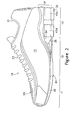
- Figure 1 is a lateral side elevational view of an article of footwear.
- Figure 2 is a medial side elevational view of the article of footwear.
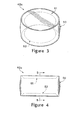
- Figure 3 is a perspective view of a support element of the article of footwear.
- Figure 4 is a side elevational view of the support element.
- Figure 5 is a cross-sectional view of the support element, as defined by section line 5-5 in Figure 4 .
- Figure 6 is an exploded perspective view of the support element.
- Figure 7 is an exploded side elevational view of the support element.
- Figure 8 is a perspective view of the support element in a non-pressurized configuration.
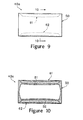
- Figure 9 is a side elevational view of the support element in the non-pressurized configuration.
- Figure 10 is a cross-sectional view of the support element in the non-pressurized configuration, as defined by section line 10-10 in Figure 9 .
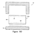
- Figure 11A-11D are schematic cross-sectional views of a mold depicting steps for manufacturing the support element.
- Figure 12 is a perspective view of a support component having four support elements.
- Figure 13 is a lateral side elevational view of another article of footwear.
- Figure 14 is a side elevational view of a portion of the article of footwear depicted in Figure 13 .
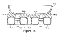
- Figure 15 is a cross-sectional of the portion of the article of footwear, as defined by section line 15-15 in Figure 14 .
- Figure 16 is an exploded side elevational view of the portion of the article of footwear depicted in Figure 13 .
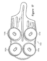
- Figure 17 is a bottom plan view of a plate member of the article of footwear depicted in Figure 13 .
- Figure 18 is a perspective view of the plate member.
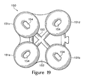
- Figure 19 is a top plan view of a support component of the article of footwear depicted in Figure 13 .
- Figure 20 is a perspective view of the support component.
- the following discussion and accompanying figures disclose an article of footwear having support elements in accordance with aspects of the present invention.
- Concepts related to the support elements are disclosed with reference to footwear having a configuration suitable for the sport of running.
- the support elements are not solely limited to footwear designed for running, however, and may be incorporated into a wide range of athletic footwear styles, including shoes that are suitable for baseball, basketball, football, rugby, soccer, tennis, volleyball, and walking, for example.
- the support elements may be incorporated into footwear that is generally considered to be non-athletic, including a variety of dress shoes, casual shoes, sandals, and boots.
- An individual skilled in the relevant art will appreciate, therefore, that the concepts disclosed herein with regard to the support elements apply to a wide variety of footwear styles, in addition to the specific style discussed in the following material and depicted in the accompanying figures.
- footwear 10 is depicted in Figures 1 and 2 as including an upper 20 and a sole structure 30.
- footwear 10 may be divided into three general regions: a forefoot region 11, a midfoot region 12, and a heel region 13, as defined in Figures 1 and 2 .
- footwear 10 includes two sides: lateral side 14 and medial side 15, as also defined in Figures 1 and 2 .
- Lateral side 14 is positioned to extend along a lateral side of the foot and generally passes through each of regions 11-13.
- medial side 15 is positioned to extend along an opposite medial side of the foot and generally passes through each of regions 11-13. Regions 11-13 and sides 14-15 are not intended to demarcate precise areas of footwear 10.
- regions 11-13 and sides 14-15 are intended to represent general areas of footwear 10 that provide a frame of reference during the following discussion. Although regions 11-13 and sides 14-15 apply generally to footwear 10, references to regions 11-13 and sides 14-15 may also apply specifically to upper 20, sole structure 30, or an individual component within either upper 20 or sole structure 30.
- Upper 20 is secured to sole structure 30 and defines a cavity for receiving a foot. Access to the cavity is provided by an ankle opening 21 located in heel region 11.
- a lace 22 extends in a zigzag pattern through various apertures in upper 20. Lace 22 may be utilized in a conventional manner to selectively increase a size of ankle opening 21 and modify certain dimensions of upper 20, particularly girth, to accommodate feet with varying dimensions.
- Various materials are suitable for upper 20, including leather, synthetic leather, rubber, textiles, and polymer foams, for example, that are stitched or adhesively bonded together. The specific materials utilized for upper 20 may be selected to impart wear-resistance, flexibility, air-permeability, moisture control, and comfort.
- upper 20 may exhibit the configuration of any conventional or non-conventional upper.
- Sole structure 30 is secured to a lower surface of upper 20 and includes an outsole 31 and a midsole 32.
- Outsole 31 forms a ground-engaging surface of sole structure 30 and is formed of a durable, wear-resistant material, such as rubber, that is textured to enhance traction.
- outsole 31 may be formed integral with midsole 32 or may be a lower surface of midsole 32.
- a conventional midsole is primarily formed of a polymer foam material, such as polyurethane or ethylvinylacetate, as discussed in the Background of the Invention section.
- midsole 32 defines a void 33 in heel region 13 that includes four fluid-filled support elements 40a-40d.
- Void 33 extends through sole structure 30 from lateral side 14 to medial side 15 and has an upper surface 34 and an opposite lower surface 35.
- midsole 32 may be substantially formed from a polymer foam material, plates or other elements in midsole 32 may define void 33.
- Each of support elements 40a-40d extend between surfaces 34 and 35 to provide ground reaction force attenuation as footwear 10 impacts the ground during running, walking, or other ambulatory activities.
- support elements 40a-40d may impart stability or otherwise control foot motions, such as the degree of pronation.
- Sole structure 30 may also include an insole positioned within the cavity formed by upper 20 and located to contact a plantar (i.e., lower) surface of the foot, thereby enhancing the overall comfort of footwear 10.
- the primary portions of support element 40a are a fluid-filled chamber 50 and a pair of inserts 61 and 62.
- Chamber 50 is a sealed bladder formed from a polymer material that encloses a pressurized fluid.
- the fluid places an outward force upon chamber 50 that tends to distend surfaces of chamber 50. That is, the fluid has sufficient pressure to cause various surfaces of chamber 50 to bulge or otherwise protrude outward.
- Surfaces 34 and 35 of void 33 have a generally planar configuration in areas where support element 40a contacts and is secured to midsole 31.
- Inserts 61 and 62 are secured to an exterior of chamber 50 to limit the distension in various surfaces of chamber 50 and provide generally planar areas that may join with surfaces 34 and 35 of void 33.
- Chamber 50 has a generally cylindrical structure that includes a first surface 51, an opposite second surface 52, and a sidewall surface 53 extending between first surface 51 and second surface 52.
- Chamber 50 is formed, as described in greater detail below, from a pair of polymer barrier layers that are substantially impermeable to a pressurized fluid contained by chamber 50.
- One of the barrier layers forms both first surface 51 and sidewall surface 53, and the other of the barrier layers forms second surface 52.
- the barrier layers are bonded together around their respective peripheries to define a peripheral bond 54 that seals the pressurized fluid within chamber 50.
- each of the barrier layers may form portions of sidewall surface 53 such that peripheral bond 54 is positioned between first surface 51 and second surface 52.
- Inserts 61 and 62 have a generally circular structure and are bonded or otherwise secured to an exterior of chamber 50. More specifically, insert 61 is recessed into and secured to first surface 51, and insert 62 is recessed into and secured to second surface 52. Each of inserts 61 and 62 have a plate-like structure with two opposite surfaces and a tapered sidewall. That is, the area of the surface that faces outward is greater than the area of the surface that faces inward and is bonded to chamber 50, and the sidewall forms the taper between the two surfaces. In further embodiments, each of the surfaces of inserts 61 and 62 may have substantially equal areas.
- inserts 61 and 62 are recessed into chamber 50, as depicted in Figure 5 . More particularly, the polymer material of chamber 50 is secured to one surface and the tapered sidewall of each of inserts 61 and 62. The polymer material of chamber 50 extends, therefore, from a lower surface of support element 40a to an upper surface of support element 40a. Sidewall 53 forms, therefore, the exposed portion of support element 40a when incorporated into footwear 10.
- Inserts 61 and 62 may have a diameter that is equal to a diameter of surfaces 51 and 52. Alternatively, the diameter of inserts 61 and 62 may be in a range of 90% to 110%, for example, of a diameter of surfaces 51 and 52, or the diameter of inserts 61 and 62 may vary beyond this range. Accordingly, inserts 61 and 62 may have a lesser or greater area than surfaces 51 and 52.
- Inserts 61 and 62 are depicted as being substantially identical to each other. In some embodiments, however, the diameters, thicknesses, or materials forming inserts 61 and 62 may be different. Furthermore, each of inserts 61 and 62 may include unique protrusions or indentations that assist with positioning support element 40a in void 33 of midsole 32. Each of inserts 61 and 62 are also depicted as having substantially constant thicknesses. In some embodiments, however, the thickness of insert 61, for example, may vary such that one side of insert 61 is thicker than an opposite side of insert 61. Similarly, the thickness of insert 61 may vary such that a central area is thicker than a peripheral area.
- Figures 3-7 depict support element 40a in a pressurized configuration, wherein the fluid within support element 40a places an outward force upon first surface 51, second surface 52, and sidewall surface 53 due to differences in pressure between air surrounding chamber 50 and the fluid.
- Figures 8-10 depict support element 40a in a non-pressurized configuration, wherein differences in pressure between air surrounding chamber 50 and the fluid are minimal.
- inserts 61 and 62 exhibit a substantially planar structure. That is, neither of inserts 61 and 62 exhibit substantial curvature or other non-planar characteristics.
- inserts 61 and 62 each bow inward and toward a center of support element 40a.
- both of inserts 61 and 62 exhibit a curved structure in the non-pressurized configuration. Accordingly, the outward force of the pressurized fluid within chamber 50 tends to deform inserts 61 and 62 from a non-planar structure to a generally planar structure.
- Support elements 40a-40d are devoid of internal connections between first surface 51 and second surface 52. That is, first surface 51 and second surface 52 are not connected through an interior of support elements 40a-40d.
- Some prior art fluid-filled bladders in footwear include a plurality of internal connections to prevent surfaces from bulging or otherwise protruding outward. The presence of inserts 61 and 62, however, limits the degree to which first surface 51 and second surface 52 protrude outward. Accordingly, internal connections between first surface 51 and second surface 52 are not necessary. In some embodiments, however, internal connections may be utilized.
- thermoplastic polymer materials may be utilized for chamber 50, and particularly the barrier layers, including polyurethane, polyester, polyester polyurethane, and polyether polyurethane.
- Another suitable material for chamber 50 is a film formed from alternating layers of thermoplastic polyurethane and ethylene-vinyl alcohol copolymer, as disclosed in U.S. Patent Numbers 5,713,141 and 5,952,065 to Mitchell et al , hereby incorporated by reference.
- a variation upon this material wherein the center layer is formed of ethylene-vinyl alcohol copolymer; the two layers adjacent to the center layer are formed of thermoplastic polyurethane; and the outer layers are formed of a regrind material of thermoplastic polyurethane and ethylene-vinyl alcohol copolymer may also be utilized.
- Chamber 50 may also be formed from a flexible microlayer membrane that includes alternating layers of a gas barrier material and an elastomeric material, as disclosed in U.S. Patent Numbers 6,082,025 and 6,127,026 to Bonk et al ., both hereby incorporated by reference.
- numerous thermoplastic urethanes may be utilized, such as PELLETHANE, a product of the Dow Chemical Company; ELASTOLLAN, a product of the BASF Corporation; and ESTANE, a product of the B.F. Goodrich Company, all of which are either ester or ether based.
- thermoplastic urethanes based on polyesters, polyethers, polycaprolactone, and polycarbonate macrogels may be employed, and various nitrogen blocking materials may also be utilized. Additional suitable materials are disclosed in U.S. Patent Numbers 4,183,156 and 4,219,945 to Rudy , hereby incorporated by reference. Further suitable materials include thermoplastic films containing a crystalline material, as disclosed in U.S. Patent Numbers 4,936,029 and 5,042,176 to Rudy , hereby incorporated by reference, and polyurethane including a polyester polyol, as disclosed in U.S. Patent Numbers 6,013,340 ; 6,203,868 ; and 6,321,465 to Bonk et al ., also hereby incorporated by reference.
- Inserts 61 and 62 may be formed from a diverse range of materials. Suitable materials for inserts 61 and 62 include polyester, thermoset urethane, thermoplastic urethane, various nylon formulations, blends of these materials, or blends that include glass fibers. In addition, inserts 61 and 62 may be formed from a high flex modulus polyether block amide, such as PEBAX, which is manufactured by the Atofina Company. Polyether block amide provides a variety of characteristics that benefit the present invention, including high impact resistance at low temperatures, few property variations in the temperature range of minus 40 degrees Celsius to positive 80 degrees Celsius, resistance to degradation by a variety of chemicals, and low hysteresis during alternative flexure.
- PEBAX high flex modulus polyether block amide
- inserts 61 and 62 are a polybutylene terephthalate, such as HYTREL, which is manufactured by E.I. duPont de Nemours and Company.
- Composite materials may also be formed by incorporating glass fibers or carbon fibers into the polymer materials discussed above in order to enhance the strength of inserts 61 and 62.
- the material forming inserts 61 and 62 may exhibit a greater modulus of elasticity than the material forming chamber 50. Whereas the material forming chamber 50 is generally flexible, the material forming inserts 61 and 62 may exhibit semi-rigid or rigid properties.
- the fluid within chamber 50 may be any of the gasses disclosed in U.S. Patent Number 4,340,626 to Rudy , hereby incorporated by reference, such as hexafluoroethane and sulfur hexafluoride, for example.
- the fluid may also include gasses such as pressurized octafluorapropane, nitrogen, or air.
- various gels or liquids may be sealed within chamber 50. Accordingly, a variety of fluids are suitable for chamber 50. With regard to pressure, a suitable fluid pressure is fifteen pounds per square inch, but may range from zero to thirty pounds per square inch. Accordingly, the fluid pressure within chamber 50 may be relatively high, or the fluid pressure may be at ambient pressure or at a pressure that is slightly elevated from ambient.
- considerations include the shape and thickness of inserts 61 and 62, the materials forming inserts 61 and 62, the materials forming chamber 50, the type of footwear insert 40a is used in, the weight of the wearer, and the sport the wearer with participate in, for example.
- Each of support elements 40a-40d may enclose a fluid with a substantially similar fluid pressure. More particularly, the fluid pressure within support elements 40a-40d may be the same when sole structure 30 is in an uncompressed state. As portions of sole structure 30 are compressed, the fluid pressure will rise in those support elements 40a-40d that experience the greatest compression. For example, upon impact with the ground, support element 40a may be more compressed than support elements 40b-40d, and the fluid pressure within support element 40a will be greater than the fluid pressure within support elements 40b-40d. As footwear 10 comes to rest and sole structure 30 is no longer compressed, the fluid pressure within each of support elements 40a-40d will return to being the same.
- support element 40a-40d may be different when sole structure 30 is in an uncompressed state.
- support element 40a may initially have a fluid pressure of 15 pounds per square inch and each of support elements 40b-40d may have a greater initial fluid pressure of 20 pounds per square inch. Accordingly, the relative pressures within support elements 40a-40d may vary significantly.
- mold 70 includes a first mold portion 71 and a corresponding second mold portion 72. When joined together, mold portions 71 and 72 define a cavity having dimensions substantially equal to the exterior dimensions of one of support elements 40a-40d. Mold 70 may be utilized for thermoforming chamber 50 and simultaneously bonding or otherwise securing inserts 61 and 62 to chamber 50. In general, inserts 61 and 62 are placed in or adjacent to mold portions 71 and 72, and a pair of barrier layers 41 and 42, formed from a thermoplastic polymer material, for example are placed between mold portions 71 and 72.
- Barrier layers 41 and 42 which form chamber 50, are then drawn into the contours of mold 70 such that inserts 61 and 62 are respectively recessed into and bonded to barrier layers 41 and 42.
- mold portions 71 and 72 compress barrier layers 41 and 42 together to form peripheral bond 54.
- chamber 50 may be pressurized with the fluid and sealed, thereby forming support element 40a.
- inserts 61 and 62 may then be cleansed with a detergent or alcohol, for example, in order to remove surface impurities, such as a mold release agent or fingerprints.
- a detergent or alcohol for example, in order to remove surface impurities, such as a mold release agent or fingerprints.
- the surfaces of inserts 61 and 62 may also be plasma treated to enhance bonding with chamber 50.
- inserts 61 and 62 are placed between mold portions 71 and 72 and then positioned adjacent to mold portions 71 and 72, as depicted in Figures11A and 11B .
- a variety of techniques may be utilized to secure inserts 61 and 62 to mold portions 71 and 72, including a vacuum system, various seals, or non-permanent adhesive elements, for example.
- inserts 61 and 62 may include various tabs that define apertures, and mold portions 71 and 72 may include protrusions that engage the apertures to secure inserts 61 and 62 within mold 70.
- a plurality of conduits may extend through mold 70 in order to channel a heated liquid, such as water or oil, through mold 70, thereby raising the overall temperature of mold 70.
- a heated liquid such as water or oil
- inserts 61 and 62 are positioned within mold 70, and inserts 61 and 62 conduct the heat from mold 70, thereby raising the temperature of inserts 61 and 62.
- inserts 61 and 62 may be heated prior to placement within mold 70 in order to decrease manufacturing times, or various conductive or radiative heaters may be utilized to heat inserts 61 and 62 while located within mold 70.
- the temperature of mold 70 may vary depending upon the specific materials utilized for support element 40a.
- barrier layers 41 and 42 are heated and positioned between mold portions 71 and 72, as depicted in Figure 11B . The temperature to which barrier layers 41 and 42 are heated also depends upon the specific material used.
- the thickness of barrier layer 41 prior to molding may be greater than the thickness of barrier layer 42.
- barrier layers 41 and 42 may exhibit different thicknesses prior to molding, each of barrier layers 41 and 42 may have a substantially uniform thickness following molding.
- a suitable thickness range for barrier layer 41 prior to molding is 0.045 to 0.110 inches, with one preferred thickness being 0.090 inches, and a suitable thickness range for barrier layer 42 prior to molding is 0.035 to 0.065 inches, with one preferred thickness being 0.045 inches.
- barrier layer 42 only forms second surface 52 of chamber 50
- barrier layer 41 forms both first surface 51 and sidewall surface 53 of chamber 50.
- barrier layer 41 may stretch to a greater degree than barrier layer 42 in order to form both surface 51 and sidewall surface 53. Accordingly, differences between the original, pre-stretched thicknesses of barrier layers 41 and 42 compensate for thinning in barrier layer 41 that may occur when barrier layer 41 is stretched or otherwise distorted during the formation of first surface 51 and sidewall surface 53.
- mold portions 71 and 72 translate toward each other such that barrier layers 41 and 42 are shaped, as depicted in Figure 11C .
- a fluid such as air
- Air may also be removed from the area between barrier layers 41 and 42 and mold portions 71 and 72 through various vents, thereby drawing barrier layers 41 and 42 onto the surfaces of mold portions 71 and 72. That is, at least a partial vacuum may be formed between the barrier layers 41 and 42 and the surfaces of mold portions 71 and 72.
- barrier layers 41 and 42 are drawn onto the surfaces of mold portions 71 and 72 into contact with inserts 61 and 62. Accordingly, barrier layers 41 and 42 contact and are bonded to inserts 61 and 62 during this portion of the manufacturing process.
- barrier layers 41 and 42 conform to the shape of mold 70 and are bonded together. More specifically, barrier layers 41 and 42 stretch, bend, or otherwise conform to extend along the surfaces of the cavity within mold 70 and form the general shape of chamber 50. Although barrier layers 41 and 42 conform to extend along the surfaces of the cavity, barrier layers 41 and 42 generally do not contact the portions of mold portions 71 and 72 that are covered by inserts 61 and 62. Rather, barrier layer 41 contacts and is compressed against the inward-facing surface of insert 61, thereby bonding barrier layer 41 to insert 61. Similarly, barrier layer 42 contacts and is compressed against the inward-facing surface of insert 62, thereby bonding barrier layer 42 to insert 62.
- inserts 61 and 62 are generally flush with surfaces of chamber 50.
- barrier layers 41 and 42 and inserts 61 and 62 are compressed against surfaces of mold 70.
- Barrier layer 41 contacts the inward-facing surface of insert 61, conforms to the shape of insert 61, extends around the tapered sides of insert 61, and contacts the surface of mold portion 71. In this manner, insert 61 is recessed into chamber 50.
- barrier layer 42 contacts the inward-facing surface of insert 62, conforms to the shape of insert 62, extends around the tapered sides of insert 62, and contacts the surface of mold portion 72. In this manner, insert 62 is recessed into chamber 50.
- a plurality of apertures may be formed through selected locations of inserts 61 and 62. These apertures may provide outlets for air and may correspond in position with the various vents in mold 70.
- mold portions 71 and 72 separate such that the combination of chamber 50 and inserts 61 and 62 may be removed from mold 70, as depicted in Figure 11D .
- the polymer materials forming chamber 50 and inserts 61 and 62 are then permitted to cool, and a pressurized fluid may be injected in a conventional manner.
- a conduit formed during the bonding of barrier layers 41 and 42 may be utilized to inject the fluid, and the conduit may then be sealed at a position that corresponds with peripheral bond 54 to seal chamber 50.
- excess portions of barrier layers 41 and 42 may be trimmed or otherwise removed from support element 40a. The excess portions may then be recycled or reutilized to form additional barrier layers.
- excess portions of barrier layers 41 and 42 may remain in order to form a support component, as in Figure 12 , that may be incorporated into footwear 10.
- peripheral bond 54 affects placement of peripheral bond 54.
- One advantage of placing peripheral bond 54 at the interface of second surface 52 and sidewall surface 53 is that unobstructed visibility is retained through exposed portions of sidewall surface 53.
- This configuration requires that barrier layer 41 stretch to a greater degree than barrier layer 42 in order to also form sidewall surface 53.
- peripheral bond 54 may be positioned at a midpoint of sidewall surface 53, or peripheral bond 54 may be positioned at the interface of first surface 51 and sidewall surface 53. Accordingly, the elevation of peripheral bond 54 may be selected to limit or otherwise control the degree of stretch in barrier layers 41 and 42.
- barrier layers 41 and 42 stretch during the thermoforming process, the thickness of barrier layers 41 and 42 decreases.
- the desired resulting thickness of barrier layers 41 and 42 generally depends upon the specific use and configuration of footwear 10. Selecting the position of peripheral bond 54 and the initial thicknesses of barrier layers 41 and 42 provides control over the degree of stretch in barrier layers 41 and 42. Accordingly, the position of peripheral bond 54 and the initial thicknesses of barrier layers 41 and 42 may be selected in order to minimize the overall thickness of bladder chamber 50 while retaining sufficient strength.
- thermoforming process discussed above is a suitable manner of forming support element 40a
- a blow-molding process may also be utilized.
- a suitable blow-molding process involves positioning inserts 61 and 62 within at least one of two mold portions and then positioning a parison between the mold portions, such as mold portions 71 and 72.
- the parison is a generally hollow and tubular structure of molten polymer material.
- the molten polymer material is extruded from a die.
- the wall thickness of the parison may be substantially constant, or may vary around the perimeter of the parison. Accordingly, a cross-sectional view of the parison may exhibit areas of differing wall thickness.
- Suitable materials for the parison include the materials discussed above with respect to chamber 50. Following placement of the parison between the mold portions, the mold portions close upon the parison and pressurized air within the parison induces the liquefied elastomeric material to contact the surfaces of the mold. In addition, closing of the mold portions and the introduction of pressurized air induces the liquefied elastomeric material to contact the surfaces of inserts 61 and 62. Air may also be evacuated from the area between the parison and the mold to further facilitate molding and bonding. Accordingly, support element 40a may also be formed through a blow molding process wherein inserts 61 and 62 are placed within the mold prior to the introduction of the molten polymer material.
- support element 40a may be formed separate from inserts 61 and 62 and subsequently bonded together.
- a dual-injection technique may also be utilized to simultaneously form chamber 50 and inserts 61 and 62 from separate materials.
- a first element corresponding with first surface 51 and sidewall surface 53 may be formed, a second element corresponding with second surface 52 may be joined thereto, and a pair of third elements corresponding with inserts 61 and 62 may then be secured to the exterior.
- structures having the general shape and features of support element 40a may be formed from a variety of processes.
- support element 40a The above discussion related to the formation of support element 40a.
- the various concepts discussed above apply, however, to each of support elements 40b-40d. Accordingly, a substantially similar procedure may be utilized to manufacture support elements 40b-40d.
- the various concepts discussed above may also be applied to other support element configurations.
- Support elements 40a-40d are arranged such that support element 40a is positioned adjacent lateral side 14, support element 40b is positioned adjacent lateral side 14 and forward of support element 40a, support element 40c is positioned adjacent medial side element 40c. Accordingly, support elements 40a-40d are arranged in a square configuration. In further embodiments, support elements 40a-40d may be offset from each other, or a lesser or greater number of support elements may be located within heel region 13. Additional support elements similar to support elements 40a-40d may also be positioned in one or both of forefoot region 11 and midfoot region 12. Alternatively, support elements similar to support elements 40a-40d may be limited to either of forefoot region 11 and midfoot region 12. Accordingly, the number and positions of support elements 40a-40d may vary significantly.
- support element 40a may vary significantly from the general structure discussed above and depicted in Figures 1-10 .
- support elements 40a-40d may be formed to exhibit a shape that varies from cylindrical to include cubic and spherical.
- sidewall surface 53 may have an elliptical, triangular, or hexagonal shape in cross-section, for example.
- inserts 61 and 62 may have a planar shape in the non-pressurized configuration that becomes outwardly-curved in the pressurized configuration. Inserts 61 and 62 may also be bonded to chamber 50 in a manner that does not include recessing inserts 61 and 62 into surfaces 51 and 52.
- Inserts 61 and 62 are bonded to upper and lower surfaces of void 33 in midsole 32, thereby securing support element 40a to footwear 10.
- midsole 32 may include one or more plates, for example, that include bonding locations for support element 40a.
- inserts 61 and 62 may be formed of unitary (i.e., one-piece) construction with the plates. That is, inserts 61 and 62 may be formed of unitary construction with the polymer foam, plates, or other elements of midsole 31 that define void 33. This configuration reduces the number of connections necessary to join support element 40a to midsole 31, and may also increase durability and reduce the number of manufacturing steps necessary for footwear 10.
- Support elements 40b-40d are depicted as having a substantially identical structure to support element 40a. In some embodiments of the invention, however, the relative heights of support elements 40a-40d may vary, or the pressures of the fluid within support elements 40a-40d may vary. In order to limit pronation (i.e., roll of the foot from lateral side 14 to medial side 15), support elements 40a and 40b may have a lesser fluid pressure than support elements 40c and 40d, or the thickness of the barrier layers forming support elements 40a and 40b may be less than the thickness of the barrier layers forming support elements 40c and 40d. Accordingly, the relative structures of support elements 40a-40d may vary significantly.
- inserts 61 and 62 are described above as having a plate-like structure with two opposite surfaces and a tapered sidewall.
- one or both of inserts 61 and 62 may define various ribs that enhance the stiffness of inserts 61 and 62.
- Inserts 61 and 62 may also be formed to have various apertures that define a grid-like structure.
- inserts 61 and 62 may each be formed of two or more elements that are recessed into surfaces 51 and 52.
- the two elements may be formed of different materials to impart different properties to areas of support elements 40a-40d. Accordingly, inserts 61 and 62 may have a variety of configurations, in addition to the configuration of a plate.
- support elements 40a-40d are intended to provide an example of support elements within the scope of aspects of the present invention. Various alternate configurations, however, may also be utilized.
- a support component having support elements 40a-40d connected by an x-shaped conduit 43 is depicted.
- conduit 43 places each of support elements 40a-40d in fluid communication.
- support elements 40a-40d are formed as individual elements, a pressure increase associated with one of support elements 40a-40d does not increase pressure within other support elements 40a-40d.
- increases in pressure are uniformly distributed among the various support elements 40a-40d.
- support elements 40a-40d may be formed as a unit or each of support elements 40a-40d may be formed separately and subsequently joined.
- the fluid pressure within support elements 40a-40d may be the same when sole structure 30 is in an uncompressed state.
- Conduit 43 may be utilized to ensure that the fluid pressure in each of support elements 40a-40d is substantially identical. That is, the support component having support elements 40a-40d and conduit 43 may be formed and pressurized. In this state, each of support elements 40a-40d will have a substantially identical fluid pressure. Conduit 43 can then be sealed or otherwise blocked to remove support elements 40a-40d from fluid communication with each other. In effect, therefore, sealing conduit 43 will isolate each of support elements 40a-40d from fluid communication and ensure that the initial pressure within each of support elements 40a-40d is substantially identical.
- Sealing conduit 43 may also utilized to isolate one of support elements 40a-40d from fluid communication with other support elements 40a-40d.
- the portion of conduit 43 adjacent to support element 40a may be sealed to prevent fluid communication between support element 40a and each of support elements 40b-40d. Sealing only a portion of conduit 43 may also be utilized to vary the fluid pressure among support elements 40a-40d.
- the support component having support elements 40a-40d may be inflated to a first pressure, and the portion of conduit 43 adjacent to support element 40a may be sealed to prevent further pressure increases. The remaining support elements 40b-40d may then be pressurized to a higher fluid pressure.
- a similar process is disclosed in U.S. Patent Number 5,353,459 to Potter, et al .
- FIG. 13 Another article of footwear 100 is depicted in Figure 13 as including an upper 120 and a sole structure 130.
- Upper 120 is secured to sole structure 130 and may exhibit the general configuration of upper 20 or any conventional or non-conventional upper.
- a portion of sole structure 130 that is primarily located in a heel region of footwear 100 is depicted in Figures 14-16 .
- This portion of sole structure 130 is secured to a lower surface of upper 120 and includes an outsole 131, a plate 140, and a support component 150.
- Outsole 131 forms a ground-engaging surface of sole structure 130 and may be formed from one or more durable, wear-resistant elements that are textured to enhance traction.
- Plate 140 is positioned adjacent to upper 120 and provides a surface for attaching chambers 150.
- a polymer foam material such as polyurethane or ethylvinylacetate, may extend between plate 140 and upper 120.
- Support component 150 extends between plate 140 and outsole 131 and includes four chambers 151a-151d.
- Other portions of sole structure 130 located in a midfoot and forefoot region may have a similar configuration.
- Plate 140 is formed from a semi-rigid polymer material and extends along a lower surface of upper 120. As depicted in Figures 17 an 18, a lower surface of plate 140 defines four attachment members 141a-141d and a plurality of ribs 142. Attachment members 141a-141 d are formed of unitary (i.e., one-piece) construction with plate 140 and extend downward from plate 140 to respectively engage chambers 151a-151d, and the lower surfaces of attachment members 141a-141d are contoured to mate with chambers 151a-151d. Ribs 142 extend in a longitudinal direction of footwear 100 and enhance the stiffness of sole structure 130.
- Suitable materials for plate 140 include a variety of polymer materials and any of the materials discussed above for inserts 61 and 62, for example.
- attachment members 141a-141d may be formed of a different material than a remainder of plate 140.
- attachment members 141a-141d may be formed of a material with a different color than the remainder of plate 140.
- attachment members 141a-141d may be formed from a clear or at least partially clear material, whereas the remainder of plate 140 may be formed from a colored and opaque material. Other properties, such as hardness and density, may also vary between attachment members 141a-141d and the remainder of plate 140. Accordingly, a dual injection molding process, for example, may be utilized to form plate 140.
- attachment members 141 a-141 d may be formed separate from plate 140 and subsequently attached during the manufacture of footwear 100.
- Support component 150 is formed from a barrier material that is substantially impermeable to a pressurized fluid contained by chambers 151a-151d.
- each of chambers 151a-151d may be formed from a first barrier layer that is bonded to a second barrier layer. More particularly, the first barrier layer may define a first surface and a sidewall surface of chambers 151a-151d, and the second barrier layer may define a second surface of chambers 151a-151d. Accordingly, the barrier layers may be bonded together around the peripheries of chambers 151 a-151 d to define peripheral bonds that seal the pressurized fluid within support component 150. In further embodiments, each of the barrier layers may form portions of the sidewall surface such that the peripheral bonds are positioned between the first surface and the second surface.
- the barrier layers forming support component 150 extends between chambers 151a-151d to form a base 152 that connects chambers 151a-151d.
- base 152 When incorporated into footwear 100, base 152 is positioned adjacent outsole 131, but may be positioned adjacent plate 140.
- An x-shaped conduit 153 places each of chambers 151a-151d in fluid communication. Accordingly, an increase in pressure within one of chambers 151 a-151d induces a corresponding increase in pressure in the other chambers 151a-151d.
- conduit 153 may be absent such that chambers 151 a-151 d are not in fluid communication.
- base 152 may be absent such that chambers 151a-151d are separate from each other.
- Inserts 61 and 62 were discussed above as limiting the degree to which first surface 51 and second surface 52 protrude outward due to the pressure of the fluid within chamber 50. Similar inserts may be utilized with chambers 151a-151d. As depicted in Figures 19 and 20 , however, each of chambers 151a-151d include an internal bond 154 that extends between opposite surfaces and limits the degree to which the opposite surfaces protrude outward. Accordingly, structures similar to inserts 61 and 62 may be absent from chambers 151a-151d. Each of chambers 151a-151d define various centrally-located indentations in areas corresponding with bond 154. Attachment members 141a-141d are each contoured to extend into the indentations.
- attachment members 141a-141d may be formed from a clear or at least partially clear material.
- the polymer material forming chambers 151a-151d may also be clear or at least partially clear such that the optical properties of attachment members 141a-141d and chambers 151a-151d are similar. Together, attachment members 141a-141d and chambers 151a-151d form a portion of a thickness of sole structure 130.
- sole structure 130 has the appearance that chambers 151a-151d form a greater portion of the thickness of sole structure 130.
- attachment members 141a-141d and chambers 151a-151d from a material with similar optical properties imparts the appearance that chambers 151a-151d extend from outsole 131 to upper portions of plate 140.
- attachment members 141a-141d and chambers 151a-151d may be formed from materials that are similarly colored, materials that have similar surface textures, materials with similar designs incorporated therein, or materials with any other properties that may impart similar appearances. Accordingly, attachment members 141a-141d and chambers 151a-151d may be formed from materials with a substantially identical color or transparency, for example, to impart optical similarity.
- sole structure 130 includes various elements that extend downward from upper 120 and each include an individual plate portion, chamber portion, and outsole portion. Whereas support component 150 includes four chambers 151a-151d, each of these elements include a single chamber. In some embodiments, the heel region of sole structure 130 may have a similar configuration wherein each of chambers 151 a-151 d are separate from each other.
Abstract
Description
- A conventional article of athletic footwear includes two primary elements, an upper and a sole structure. The upper provides a covering for the foot that securely receives and positions the foot with respect to the sole structure. In addition, the upper may have a configuration that protects the foot and provides ventilation, thereby cooling the foot and removing perspiration. The sole structure is secured to a lower surface of the upper and is generally positioned between the foot and the ground to attenuate ground reaction forces. The sole structure may also provide traction and control foot motions, such as over pronation. Accordingly, the upper and the sole structure operate cooperatively to provide a comfortable structure that is suited for a wide variety of ambulatory activities, such as walking and running.
- The sole structure of athletic footwear generally exhibits a layered configuration that includes a comfort-enhancing insole, a resilient midsole formed from a polymer foam, and a ground-contacting outsole that provides both abrasion-resistance and traction. Suitable polymer foam materials for the midsole include ethylvinylacetate or polyurethane that compress resiliently under an applied load to attenuate ground reaction forces and absorb energy. Conventional polymer foam materials are resiliently compressible, in part, due to the inclusion of a plurality of open or closed cells that define an inner volume substantially displaced by gas. That is, the polymer foam includes a plurality of bubbles that enclose the gas. Following repeated compressions, the cell structure may deteriorate, thereby resulting in decreased compressibility of the foam. Accordingly, the force attenuation characteristics of the midsole may decrease over the lifespan of the footwear.
- One manner of reducing the weight of a polymer foam midsole and decreasing the effects of deterioration following repeated compressions is disclosed in
U.S. Patent Number 4,183,156 to Rudy , hereby incorporated by reference, in which cushioning is provided by a fluid-filled bladder formed of an elastomeric materials. The bladder includes a plurality of tubular chambers that extend longitudinally along a length of the sole structure. The chambers are in fluid communication with each other and jointly extend across the width of the footwear. The bladder may be encapsulated in a polymer foam material, as disclosed inU.S. Patent Number 4,219,945 to Rudy , hereby incorporated by reference. The combination of the bladder and the encapsulating polymer foam material functions as a midsole. Accordingly, the upper is attached to the upper surface of the polymer foam material and an outsole or tread member is affixed to the lower surface. - Bladders of the type discussed above are generally formed of an elastomeric material and are structured to have upper and lower portions that enclose one or more chambers therebetween. The chambers are pressurized above ambient pressure by inserting a nozzle or needle connected to a fluid pressure source into a fill inlet formed in the bladder. Following pressurization of the chambers, the fill inlet is sealed and the nozzle is removed.
- Fluid-filled bladders suitable for footwear applications may be manufactured by a two-film technique, in which two separate sheets of elastomeric film are formed to exhibit the overall peripheral shape of the bladder. The sheets are then bonded together along their respective peripheries to form a sealed structure, and the sheets are also bonded together at predetermined interior areas to give the bladder a desired configuration. That is, the interior bonds provide the bladder with chambers having a predetermined shape and size. Such bladders have also been manufactured by a blow-molding technique, wherein a molten or otherwise softened elastomeric material in the shape of a tube is placed in a mold having the desired overall shape and configuration of the bladder. The mold has an opening at one location through which pressurized air is provided. The pressurized air induces the liquefied elastomeric material to conform to the shape of the inner surfaces of the mold. The elastomeric material then cools, thereby forming a bladder with the desired shape and configuration.
- One aspect of the invention is an article of footwear having an upper and a sole structure secured to the upper. The sole structure incorporates a support element that includes a fluid-filled chamber, a first insert, and a second insert. The chamber defines a first surface, an opposite second surface, and a sidewall extending between the first surface and the second surface. The first insert is secured to the first surface and at least partially recessed into the polymer material of the chamber. The second insert is secured to the second surface.
- The chamber may have a cylindrical configuration such that the first insert is recessed into an end of the cylindrical configuration. The second insert may also be at least partially recessed into the polymer material of the chamber. In some embodiments, the chamber is devoid of internal connections that join the first surface and the second surface. In addition, the chamber may be pressurized to deform at least one of the first insert and the second insert.
- Another aspect of the invention is a method of manufacturing a fluid-filled element. The method may include a step of forming a chamber from a polymer material. An insert may be secured to a surface of the chamber. The chamber is then pressurized to deform the insert.
- The advantages and features of novelty characterizing various aspects of the invention are pointed out with particularity in the appended claims. To gain an improved understanding of the advantages and features of novelty, however, reference may be made to the following descriptive matter and accompanying drawings that describe and illustrate various embodiments and concepts related to the aspects of the invention.
- The foregoing Summary, as well as the following Detailed Description, will be better understood when read in conjunction with the accompanying drawings.
-
Figure 1 is a lateral side elevational view of an article of footwear. -
Figure 2 is a medial side elevational view of the article of footwear. -
Figure 3 is a perspective view of a support element of the article of footwear. -
Figure 4 is a side elevational view of the support element. -
Figure 5 is a cross-sectional view of the support element, as defined by section line 5-5 inFigure 4 . -
Figure 6 is an exploded perspective view of the support element. -
Figure 7 is an exploded side elevational view of the support element. -
Figure 8 is a perspective view of the support element in a non-pressurized configuration. -
Figure 9 is a side elevational view of the support element in the non-pressurized configuration. -
Figure 10 is a cross-sectional view of the support element in the non-pressurized configuration, as defined by section line 10-10 inFigure 9 . -
Figure 11A-11D are schematic cross-sectional views of a mold depicting steps for manufacturing the support element. -
Figure 12 is a perspective view of a support component having four support elements. -
Figure 13 is a lateral side elevational view of another article of footwear. -
Figure 14 is a side elevational view of a portion of the article of footwear depicted inFigure 13 . -
Figure 15 is a cross-sectional of the portion of the article of footwear, as defined by section line 15-15 inFigure 14 . -
Figure 16 is an exploded side elevational view of the portion of the article of footwear depicted inFigure 13 . -
Figure 17 is a bottom plan view of a plate member of the article of footwear depicted inFigure 13 . -
Figure 18 is a perspective view of the plate member. -
Figure 19 is a top plan view of a support component of the article of footwear depicted inFigure 13 . -
Figure 20 is a perspective view of the support component. - The following discussion and accompanying figures disclose an article of footwear having support elements in accordance with aspects of the present invention. Concepts related to the support elements are disclosed with reference to footwear having a configuration suitable for the sport of running. The support elements are not solely limited to footwear designed for running, however, and may be incorporated into a wide range of athletic footwear styles, including shoes that are suitable for baseball, basketball, football, rugby, soccer, tennis, volleyball, and walking, for example. In addition, the support elements may be incorporated into footwear that is generally considered to be non-athletic, including a variety of dress shoes, casual shoes, sandals, and boots. An individual skilled in the relevant art will appreciate, therefore, that the concepts disclosed herein with regard to the support elements apply to a wide variety of footwear styles, in addition to the specific style discussed in the following material and depicted in the accompanying figures.
- An article of
footwear 10 is depicted inFigures 1 and2 as including an upper 20 and asole structure 30. For purposes of reference in the following material,footwear 10 may be divided into three general regions: aforefoot region 11, amidfoot region 12, and aheel region 13, as defined inFigures 1 and2 . In addition,footwear 10 includes two sides:lateral side 14 andmedial side 15, as also defined inFigures 1 and2 .Lateral side 14 is positioned to extend along a lateral side of the foot and generally passes through each of regions 11-13. Similarly,medial side 15 is positioned to extend along an opposite medial side of the foot and generally passes through each of regions 11-13. Regions 11-13 and sides 14-15 are not intended to demarcate precise areas offootwear 10. Rather, regions 11-13 and sides 14-15 are intended to represent general areas offootwear 10 that provide a frame of reference during the following discussion. Although regions 11-13 and sides 14-15 apply generally tofootwear 10, references to regions 11-13 and sides 14-15 may also apply specifically to upper 20,sole structure 30, or an individual component within either upper 20 orsole structure 30. -
Upper 20 is secured tosole structure 30 and defines a cavity for receiving a foot. Access to the cavity is provided by anankle opening 21 located inheel region 11. Alace 22 extends in a zigzag pattern through various apertures in upper 20.Lace 22 may be utilized in a conventional manner to selectively increase a size ofankle opening 21 and modify certain dimensions of upper 20, particularly girth, to accommodate feet with varying dimensions. Various materials are suitable for upper 20, including leather, synthetic leather, rubber, textiles, and polymer foams, for example, that are stitched or adhesively bonded together. The specific materials utilized for upper 20 may be selected to impart wear-resistance, flexibility, air-permeability, moisture control, and comfort. More particularly, different materials may be incorporated into different areas of upper 20 in order to impart specific properties to those areas. Furthermore, the materials may be layered in order to provide a combination of properties to specific areas. Although the configuration of upper 20 discussed above is suitable forfootwear 10, upper 20 may exhibit the configuration of any conventional or non-conventional upper. -
Sole structure 30 is secured to a lower surface of upper 20 and includes anoutsole 31 and amidsole 32.Outsole 31 forms a ground-engaging surface ofsole structure 30 and is formed of a durable, wear-resistant material, such as rubber, that is textured to enhance traction. In some embodiments,outsole 31 may be formed integral withmidsole 32 or may be a lower surface ofmidsole 32. A conventional midsole is primarily formed of a polymer foam material, such as polyurethane or ethylvinylacetate, as discussed in the Background of the Invention section. In contrast with the structure of a conventional midsole,midsole 32 defines a void 33 inheel region 13 that includes four fluid-filledsupport elements 40a-40d.Void 33 extends throughsole structure 30 fromlateral side 14 tomedial side 15 and has anupper surface 34 and an oppositelower surface 35. Althoughmidsole 32 may be substantially formed from a polymer foam material, plates or other elements inmidsole 32 may definevoid 33. Each ofsupport elements 40a-40d extend betweensurfaces footwear 10 impacts the ground during running, walking, or other ambulatory activities. In addition,support elements 40a-40d may impart stability or otherwise control foot motions, such as the degree of pronation.Sole structure 30 may also include an insole positioned within the cavity formed by upper 20 and located to contact a plantar (i.e., lower) surface of the foot, thereby enhancing the overall comfort offootwear 10. - The primary portions of
support element 40a, as depicted inFigures 3-7 , are a fluid-filledchamber 50 and a pair ofinserts Chamber 50 is a sealed bladder formed from a polymer material that encloses a pressurized fluid. The fluid places an outward force uponchamber 50 that tends to distend surfaces ofchamber 50. That is, the fluid has sufficient pressure to cause various surfaces ofchamber 50 to bulge or otherwise protrude outward.Surfaces void 33 have a generally planar configuration in areas wheresupport element 40a contacts and is secured tomidsole 31.Inserts chamber 50 to limit the distension in various surfaces ofchamber 50 and provide generally planar areas that may join withsurfaces void 33. -
Chamber 50 has a generally cylindrical structure that includes afirst surface 51, an oppositesecond surface 52, and asidewall surface 53 extending betweenfirst surface 51 andsecond surface 52.Chamber 50 is formed, as described in greater detail below, from a pair of polymer barrier layers that are substantially impermeable to a pressurized fluid contained bychamber 50. One of the barrier layers forms bothfirst surface 51 andsidewall surface 53, and the other of the barrier layers formssecond surface 52. Accordingly, the barrier layers are bonded together around their respective peripheries to define aperipheral bond 54 that seals the pressurized fluid withinchamber 50. In further embodiments, each of the barrier layers may form portions ofsidewall surface 53 such thatperipheral bond 54 is positioned betweenfirst surface 51 andsecond surface 52. -
Inserts chamber 50. More specifically, insert 61 is recessed into and secured tofirst surface 51, and insert 62 is recessed into and secured tosecond surface 52. Each ofinserts chamber 50, and the sidewall forms the taper between the two surfaces. In further embodiments, each of the surfaces ofinserts - Each of
inserts chamber 50, as depicted inFigure 5 . More particularly, the polymer material ofchamber 50 is secured to one surface and the tapered sidewall of each ofinserts chamber 50 extends, therefore, from a lower surface ofsupport element 40a to an upper surface ofsupport element 40a.Sidewall 53 forms, therefore, the exposed portion ofsupport element 40a when incorporated intofootwear 10.Inserts surfaces inserts surfaces inserts surfaces -
Inserts materials forming inserts inserts positioning support element 40a invoid 33 ofmidsole 32. Each ofinserts insert 61, for example, may vary such that one side ofinsert 61 is thicker than an opposite side ofinsert 61. Similarly, the thickness ofinsert 61 may vary such that a central area is thicker than a peripheral area. -
Figures 3-7 depictsupport element 40a in a pressurized configuration, wherein the fluid withinsupport element 40a places an outward force uponfirst surface 51,second surface 52, andsidewall surface 53 due to differences in pressure betweenair surrounding chamber 50 and the fluid. For purposes of comparison,Figures 8-10 depictsupport element 40a in a non-pressurized configuration, wherein differences in pressure betweenair surrounding chamber 50 and the fluid are minimal. In the pressurized configuration, inserts 61 and 62 exhibit a substantially planar structure. That is, neither ofinserts support element 40a. That is, both ofinserts chamber 50 tends to deforminserts -
Support elements 40a-40d are devoid of internal connections betweenfirst surface 51 andsecond surface 52. That is,first surface 51 andsecond surface 52 are not connected through an interior ofsupport elements 40a-40d. Some prior art fluid-filled bladders in footwear include a plurality of internal connections to prevent surfaces from bulging or otherwise protruding outward. The presence ofinserts first surface 51 andsecond surface 52 protrude outward. Accordingly, internal connections betweenfirst surface 51 andsecond surface 52 are not necessary. In some embodiments, however, internal connections may be utilized. - A variety of thermoplastic polymer materials may be utilized for
chamber 50, and particularly the barrier layers, including polyurethane, polyester, polyester polyurethane, and polyether polyurethane. Another suitable material forchamber 50 is a film formed from alternating layers of thermoplastic polyurethane and ethylene-vinyl alcohol copolymer, as disclosed inU.S. Patent Numbers 5,713,141 and5,952,065 to Mitchell et al , hereby incorporated by reference. A variation upon this material wherein the center layer is formed of ethylene-vinyl alcohol copolymer; the two layers adjacent to the center layer are formed of thermoplastic polyurethane; and the outer layers are formed of a regrind material of thermoplastic polyurethane and ethylene-vinyl alcohol copolymer may also be utilized.Chamber 50 may also be formed from a flexible microlayer membrane that includes alternating layers of a gas barrier material and an elastomeric material, as disclosed inU.S. Patent Numbers 6,082,025 and6,127,026 to Bonk et al ., both hereby incorporated by reference. In addition, numerous thermoplastic urethanes may be utilized, such as PELLETHANE, a product of the Dow Chemical Company; ELASTOLLAN, a product of the BASF Corporation; and ESTANE, a product of the B.F. Goodrich Company, all of which are either ester or ether based. Still other thermoplastic urethanes based on polyesters, polyethers, polycaprolactone, and polycarbonate macrogels may be employed, and various nitrogen blocking materials may also be utilized. Additional suitable materials are disclosed inU.S. Patent Numbers 4,183,156 and4,219,945 to Rudy , hereby incorporated by reference. Further suitable materials include thermoplastic films containing a crystalline material, as disclosed inU.S. Patent Numbers 4,936,029 and5,042,176 to Rudy , hereby incorporated by reference, and polyurethane including a polyester polyol, as disclosed inU.S. Patent Numbers 6,013,340 ;6,203,868 ; and6,321,465 to Bonk et al ., also hereby incorporated by reference. -
Inserts inserts inserts inserts material forming inserts material forming chamber 50. Whereas thematerial forming chamber 50 is generally flexible, thematerial forming inserts - The fluid within
chamber 50 may be any of the gasses disclosed inU.S. Patent Number 4,340,626 to Rudy , hereby incorporated by reference, such as hexafluoroethane and sulfur hexafluoride, for example. The fluid may also include gasses such as pressurized octafluorapropane, nitrogen, or air. In addition to gasses, various gels or liquids may be sealed withinchamber 50. Accordingly, a variety of fluids are suitable forchamber 50. With regard to pressure, a suitable fluid pressure is fifteen pounds per square inch, but may range from zero to thirty pounds per square inch. Accordingly, the fluid pressure withinchamber 50 may be relatively high, or the fluid pressure may be at ambient pressure or at a pressure that is slightly elevated from ambient. When selecting a fluid pressure, considerations include the shape and thickness ofinserts materials forming inserts materials forming chamber 50, the type offootwear insert 40a is used in, the weight of the wearer, and the sport the wearer with participate in, for example. - Each of
support elements 40a-40d may enclose a fluid with a substantially similar fluid pressure. More particularly, the fluid pressure withinsupport elements 40a-40d may be the same whensole structure 30 is in an uncompressed state. As portions ofsole structure 30 are compressed, the fluid pressure will rise in thosesupport elements 40a-40d that experience the greatest compression. For example, upon impact with the ground,support element 40a may be more compressed thansupport elements 40b-40d, and the fluid pressure withinsupport element 40a will be greater than the fluid pressure withinsupport elements 40b-40d. Asfootwear 10 comes to rest andsole structure 30 is no longer compressed, the fluid pressure within each ofsupport elements 40a-40d will return to being the same. As an alternative, however, the fluid pressure withinsupport elements 40a-40d may be different whensole structure 30 is in an uncompressed state. As an example,support element 40a may initially have a fluid pressure of 15 pounds per square inch and each ofsupport elements 40b-40d may have a greater initial fluid pressure of 20 pounds per square inch. Accordingly, the relative pressures withinsupport elements 40a-40d may vary significantly. - One suitable manufacturing process for
support element 40a is schematically-depicted inFigures 11A-11D and involves the use of amold 70. A substantially similar process may be utilized forsupport elements 40b-40d.Mold 70 includes afirst mold portion 71 and a correspondingsecond mold portion 72. When joined together,mold portions support elements 40a-40d.Mold 70 may be utilized forthermoforming chamber 50 and simultaneously bonding or otherwise securinginserts chamber 50. In general, inserts 61 and 62 are placed in or adjacent tomold portions mold portions chamber 50, are then drawn into the contours ofmold 70 such that inserts 61 and 62 are respectively recessed into and bonded to barrier layers 41 and 42. In addition,mold portions compress barrier layers peripheral bond 54. Once barrier layers 41 and 42 have conformed to the shape ofchamber 50, inserts 61 and 62 are bonded to barrier layers 41 and 42, andperipheral bond 54 is formed,chamber 50 may be pressurized with the fluid and sealed, thereby formingsupport element 40a. - The manner in which
mold 70 is utilized to formsupport element 40a frombarrier layers inserts inserts chamber 50. - Following formation and cleansing, inserts 61 and 62 are placed between
mold portions mold portions Figures11A and11B . A variety of techniques may be utilized to secureinserts mold portions mold portions inserts mold 70. - A plurality of conduits may extend through
mold 70 in order to channel a heated liquid, such as water or oil, throughmold 70, thereby raising the overall temperature ofmold 70. As noted above, inserts 61 and 62 are positioned withinmold 70, and inserts 61 and 62 conduct the heat frommold 70, thereby raising the temperature ofinserts mold 70 in order to decrease manufacturing times, or various conductive or radiative heaters may be utilized to heat inserts 61 and 62 while located withinmold 70. The temperature ofmold 70 may vary depending upon the specific materials utilized forsupport element 40a. Following placement ofinserts mold 70, barrier layers 41 and 42 are heated and positioned betweenmold portions Figure 11B . The temperature to which barrier layers 41 and 42 are heated also depends upon the specific material used. - The thickness of
barrier layer 41 prior to molding may be greater than the thickness ofbarrier layer 42. Although barrier layers 41 and 42 may exhibit different thicknesses prior to molding, each of barrier layers 41 and 42 may have a substantially uniform thickness following molding. Although the thickness of barrier layers 41 and 42 may vary significantly, a suitable thickness range forbarrier layer 41 prior to molding is 0.045 to 0.110 inches, with one preferred thickness being 0.090 inches, and a suitable thickness range forbarrier layer 42 prior to molding is 0.035 to 0.065 inches, with one preferred thickness being 0.045 inches. Whereasbarrier layer 42 only formssecond surface 52 ofchamber 50,barrier layer 41 forms bothfirst surface 51 andsidewall surface 53 ofchamber 50. The rationale for the difference in thickness is thatbarrier layer 41 may stretch to a greater degree thanbarrier layer 42 in order to form bothsurface 51 andsidewall surface 53. Accordingly, differences between the original, pre-stretched thicknesses of barrier layers 41 and 42 compensate for thinning inbarrier layer 41 that may occur whenbarrier layer 41 is stretched or otherwise distorted during the formation offirst surface 51 andsidewall surface 53. - Once inserts 61 and 62 and barrier layers 41 and 42 are positioned,
mold portions Figure 11C . Asmold 70 contacts and compresses portions of barrier layers 41 and 42, a fluid, such as air, having a positive pressure in comparison with ambient air may be injected between barrier layers 41 and 42 to inducebarrier layers mold portions mold portions mold portions mold portions mold portions inserts inserts - As the area between barrier layers 41 and 42 is pressurized and air is removed from the area between
mold 70 and barrier layers 41 and 42, barrier layers 41 and 42 conform to the shape ofmold 70 and are bonded together. More specifically, barrier layers 41 and 42 stretch, bend, or otherwise conform to extend along the surfaces of the cavity withinmold 70 and form the general shape ofchamber 50. Although barrier layers 41 and 42 conform to extend along the surfaces of the cavity, barrier layers 41 and 42 generally do not contact the portions ofmold portions inserts barrier layer 41 contacts and is compressed against the inward-facing surface ofinsert 61, thereby bondingbarrier layer 41 to insert 61. Similarly,barrier layer 42 contacts and is compressed against the inward-facing surface ofinsert 62, thereby bondingbarrier layer 42 to insert 62. - The various outward-facing surfaces of
inserts chamber 50. As air pressurizes the area between barrier layers 41 and 42 and air is drawn out ofmold 70, barrier layers 41 and 42 and inserts 61 and 62 are compressed against surfaces ofmold 70.Barrier layer 41 contacts the inward-facing surface ofinsert 61, conforms to the shape ofinsert 61, extends around the tapered sides ofinsert 61, and contacts the surface ofmold portion 71. In this manner, insert 61 is recessed intochamber 50. Similarly,barrier layer 42 contacts the inward-facing surface ofinsert 62, conforms to the shape ofinsert 62, extends around the tapered sides ofinsert 62, and contacts the surface ofmold portion 72. In this manner, insert 62 is recessed intochamber 50. - During bonding of barrier layers 41 and 42 to
inserts barrier layer 41 and insert 61 and betweenbarrier layer 42 andinsert 62, thereby reducing the effectiveness of the bond. In order to facilitate the removal of air from the area between barrier layers 41 and 42 and inserts 61 and 62, a plurality of apertures may be formed through selected locations ofinserts mold 70. - Once
support element 40a is formed withinmold 70,mold portions chamber 50 and inserts 61 and 62 may be removed frommold 70, as depicted inFigure 11D . The polymermaterials forming chamber 50 and inserts 61 and 62 are then permitted to cool, and a pressurized fluid may be injected in a conventional manner. As an example, a conduit formed during the bonding of barrier layers 41 and 42 may be utilized to inject the fluid, and the conduit may then be sealed at a position that corresponds withperipheral bond 54 to sealchamber 50. In addition, excess portions of barrier layers 41 and 42 may be trimmed or otherwise removed fromsupport element 40a. The excess portions may then be recycled or reutilized to form additional barrier layers. When each ofsupport elements 40a-40d are formed using a single mold, excess portions of barrier layers 41 and 42 may remain in order to form a support component, as inFigure 12 , that may be incorporated intofootwear 10. - The configurations of
mold portions peripheral bond 54. One advantage of placingperipheral bond 54 at the interface ofsecond surface 52 andsidewall surface 53 is that unobstructed visibility is retained through exposed portions ofsidewall surface 53. This configuration requires thatbarrier layer 41 stretch to a greater degree thanbarrier layer 42 in order to also formsidewall surface 53. In further embodiments of the invention, however,peripheral bond 54 may be positioned at a midpoint ofsidewall surface 53, orperipheral bond 54 may be positioned at the interface offirst surface 51 andsidewall surface 53. Accordingly, the elevation ofperipheral bond 54 may be selected to limit or otherwise control the degree of stretch in barrier layers 41 and 42. - As barrier layers 41 and 42 stretch during the thermoforming process, the thickness of barrier layers 41 and 42 decreases. The desired resulting thickness of barrier layers 41 and 42 generally depends upon the specific use and configuration of
footwear 10. Selecting the position ofperipheral bond 54 and the initial thicknesses of barrier layers 41 and 42 provides control over the degree of stretch in barrier layers 41 and 42. Accordingly, the position ofperipheral bond 54 and the initial thicknesses of barrier layers 41 and 42 may be selected in order to minimize the overall thickness ofbladder chamber 50 while retaining sufficient strength. - Although the thermoforming process discussed above is a suitable manner of forming
support element 40a, a blow-molding process may also be utilized. In general, a suitable blow-molding process involves positioning inserts 61 and 62 within at least one of two mold portions and then positioning a parison between the mold portions, such asmold portions chamber 50. Following placement of the parison between the mold portions, the mold portions close upon the parison and pressurized air within the parison induces the liquefied elastomeric material to contact the surfaces of the mold. In addition, closing of the mold portions and the introduction of pressurized air induces the liquefied elastomeric material to contact the surfaces ofinserts support element 40a may also be formed through a blow molding process wherein inserts 61 and 62 are placed within the mold prior to the introduction of the molten polymer material. - A variety of other manufacturing techniques may also be utilized to form
support element 40a, in addition to thermoforming and blow-molding. For example,chamber 50 may be formed separate frominserts chamber 50 and inserts 61 and 62 from separate materials. In some embodiments, a first element corresponding withfirst surface 51 andsidewall surface 53 may be formed, a second element corresponding withsecond surface 52 may be joined thereto, and a pair of third elements corresponding withinserts support element 40a may be formed from a variety of processes. - The above discussion related to the formation of
support element 40a. The various concepts discussed above apply, however, to each ofsupport elements 40b-40d. Accordingly, a substantially similar procedure may be utilized to manufacturesupport elements 40b-40d. The various concepts discussed above may also be applied to other support element configurations. -
Support elements 40a-40d are arranged such thatsupport element 40a is positioned adjacentlateral side 14,support element 40b is positioned adjacentlateral side 14 and forward ofsupport element 40a,support element 40c is positioned adjacentmedial side element 40c. Accordingly,support elements 40a-40d are arranged in a square configuration. In further embodiments,support elements 40a-40d may be offset from each other, or a lesser or greater number of support elements may be located withinheel region 13. Additional support elements similar to supportelements 40a-40d may also be positioned in one or both offorefoot region 11 andmidfoot region 12. Alternatively, support elements similar to supportelements 40a-40d may be limited to either offorefoot region 11 andmidfoot region 12. Accordingly, the number and positions ofsupport elements 40a-40d may vary significantly. - The structure of
support element 40a, and the structures ofsupport elements 40b-40d, may vary significantly from the general structure discussed above and depicted inFigures 1-10 . As an example,support elements 40a-40d may be formed to exhibit a shape that varies from cylindrical to include cubic and spherical. Alternately,sidewall surface 53 may have an elliptical, triangular, or hexagonal shape in cross-section, for example. In some embodiments, inserts 61 and 62 may have a planar shape in the non-pressurized configuration that becomes outwardly-curved in the pressurized configuration.Inserts chamber 50 in a manner that does not include recessinginserts surfaces -
Inserts void 33 inmidsole 32, thereby securingsupport element 40a tofootwear 10. Accordingly,midsole 32 may include one or more plates, for example, that include bonding locations forsupport element 40a. In further embodiments, inserts 61 and 62 may be formed of unitary (i.e., one-piece) construction with the plates. That is, inserts 61 and 62 may be formed of unitary construction with the polymer foam, plates, or other elements ofmidsole 31 that definevoid 33. This configuration reduces the number of connections necessary to joinsupport element 40a tomidsole 31, and may also increase durability and reduce the number of manufacturing steps necessary forfootwear 10. -
Support elements 40b-40d are depicted as having a substantially identical structure to supportelement 40a. In some embodiments of the invention, however, the relative heights ofsupport elements 40a-40d may vary, or the pressures of the fluid withinsupport elements 40a-40d may vary. In order to limit pronation (i.e., roll of the foot fromlateral side 14 to medial side 15),support elements support elements support elements support elements support elements 40a-40d may vary significantly. - Each of
inserts inserts inserts Inserts surfaces support elements 40a-40d. Accordingly, inserts 61 and 62 may have a variety of configurations, in addition to the configuration of a plate. - The specific configurations of
support elements 40a-40d disclosed above are intended to provide an example of support elements within the scope of aspects of the present invention. Various alternate configurations, however, may also be utilized. Referring toFigure 12 , a support component havingsupport elements 40a-40d connected by anx-shaped conduit 43 is depicted. In contrast with theindividual support elements 40a-40d disclosed above,conduit 43 places each ofsupport elements 40a-40d in fluid communication. Whensupport elements 40a-40d are formed as individual elements, a pressure increase associated with one ofsupport elements 40a-40d does not increase pressure withinother support elements 40a-40d. When connected byconduit 43, however, increases in pressure are uniformly distributed among thevarious support elements 40a-40d. In forming the support component,support elements 40a-40d may be formed as a unit or each ofsupport elements 40a-40d may be formed separately and subsequently joined. - As noted above, the fluid pressure within
support elements 40a-40d may be the same whensole structure 30 is in an uncompressed state.Conduit 43 may be utilized to ensure that the fluid pressure in each ofsupport elements 40a-40d is substantially identical. That is, the support component havingsupport elements 40a-40d andconduit 43 may be formed and pressurized. In this state, each ofsupport elements 40a-40d will have a substantially identical fluid pressure.Conduit 43 can then be sealed or otherwise blocked to removesupport elements 40a-40d from fluid communication with each other. In effect, therefore, sealingconduit 43 will isolate each ofsupport elements 40a-40d from fluid communication and ensure that the initial pressure within each ofsupport elements 40a-40d is substantially identical. - Sealing
conduit 43 may also utilized to isolate one ofsupport elements 40a-40d from fluid communication withother support elements 40a-40d. For example, the portion ofconduit 43 adjacent to supportelement 40a may be sealed to prevent fluid communication betweensupport element 40a and each ofsupport elements 40b-40d. Sealing only a portion ofconduit 43 may also be utilized to vary the fluid pressure amongsupport elements 40a-40d. For example, the support component havingsupport elements 40a-40d may be inflated to a first pressure, and the portion ofconduit 43 adjacent to supportelement 40a may be sealed to prevent further pressure increases. The remainingsupport elements 40b-40d may then be pressurized to a higher fluid pressure. A similar process is disclosed inU.S. Patent Number 5,353,459 to Potter, et al . - Another article of
footwear 100 is depicted inFigure 13 as including an upper 120 and asole structure 130.Upper 120 is secured tosole structure 130 and may exhibit the general configuration of upper 20 or any conventional or non-conventional upper. For purposes of example, a portion ofsole structure 130 that is primarily located in a heel region offootwear 100 is depicted inFigures 14-16 . This portion ofsole structure 130 is secured to a lower surface of upper 120 and includes anoutsole 131, aplate 140, and asupport component 150.Outsole 131 forms a ground-engaging surface ofsole structure 130 and may be formed from one or more durable, wear-resistant elements that are textured to enhance traction.Plate 140 is positioned adjacent to upper 120 and provides a surface for attachingchambers 150. In some embodiments, a polymer foam material, such as polyurethane or ethylvinylacetate, may extend betweenplate 140 and upper 120.Support component 150 extends betweenplate 140 andoutsole 131 and includes fourchambers 151a-151d. Other portions ofsole structure 130 located in a midfoot and forefoot region may have a similar configuration. -
Plate 140 is formed from a semi-rigid polymer material and extends along a lower surface of upper 120. As depicted inFigures 17 an 18, a lower surface ofplate 140 defines fourattachment members 141a-141d and a plurality ofribs 142.Attachment members 141a-141 d are formed of unitary (i.e., one-piece) construction withplate 140 and extend downward fromplate 140 to respectively engagechambers 151a-151d, and the lower surfaces ofattachment members 141a-141d are contoured to mate withchambers 151a-151d.Ribs 142 extend in a longitudinal direction offootwear 100 and enhance the stiffness ofsole structure 130. - Suitable materials for
plate 140 include a variety of polymer materials and any of the materials discussed above forinserts attachment members 141a-141d may be formed of a different material than a remainder ofplate 140. Similarly,attachment members 141a-141d may be formed of a material with a different color than the remainder ofplate 140. As an example,attachment members 141a-141d may be formed from a clear or at least partially clear material, whereas the remainder ofplate 140 may be formed from a colored and opaque material. Other properties, such as hardness and density, may also vary betweenattachment members 141a-141d and the remainder ofplate 140. Accordingly, a dual injection molding process, for example, may be utilized to formplate 140. In some embodiments, attachment members 141 a-141 d may be formed separate fromplate 140 and subsequently attached during the manufacture offootwear 100. -
Support component 150 is formed from a barrier material that is substantially impermeable to a pressurized fluid contained bychambers 151a-151d. As withchamber 50 discussed above, each ofchambers 151a-151d may be formed from a first barrier layer that is bonded to a second barrier layer. More particularly, the first barrier layer may define a first surface and a sidewall surface ofchambers 151a-151d, and the second barrier layer may define a second surface ofchambers 151a-151d. Accordingly, the barrier layers may be bonded together around the peripheries of chambers 151 a-151 d to define peripheral bonds that seal the pressurized fluid withinsupport component 150. In further embodiments, each of the barrier layers may form portions of the sidewall surface such that the peripheral bonds are positioned between the first surface and the second surface. - The barrier layers forming
support component 150 extends betweenchambers 151a-151d to form a base 152 that connectschambers 151a-151d. When incorporated intofootwear 100,base 152 is positionedadjacent outsole 131, but may be positionedadjacent plate 140. Anx-shaped conduit 153 places each ofchambers 151a-151d in fluid communication. Accordingly, an increase in pressure within one of chambers 151 a-151d induces a corresponding increase in pressure in theother chambers 151a-151d. In some embodiments,conduit 153 may be absent such that chambers 151 a-151 d are not in fluid communication. Alternately,base 152 may be absent such thatchambers 151a-151d are separate from each other. -
Inserts first surface 51 andsecond surface 52 protrude outward due to the pressure of the fluid withinchamber 50. Similar inserts may be utilized withchambers 151a-151d. As depicted inFigures 19 and20 , however, each ofchambers 151a-151d include aninternal bond 154 that extends between opposite surfaces and limits the degree to which the opposite surfaces protrude outward. Accordingly, structures similar toinserts chambers 151a-151d. Each ofchambers 151a-151d define various centrally-located indentations in areas corresponding withbond 154.Attachment members 141a-141d are each contoured to extend into the indentations. - As discussed above,
attachment members 141a-141d may be formed from a clear or at least partially clear material. The polymermaterial forming chambers 151a-151d may also be clear or at least partially clear such that the optical properties ofattachment members 141a-141d andchambers 151a-151d are similar. Together,attachment members 141a-141d andchambers 151a-151d form a portion of a thickness ofsole structure 130. By formingattachment members 141a-141d from a material with similar optical properties aschambers 151a-151d,sole structure 130 has the appearance thatchambers 151a-151d form a greater portion of the thickness ofsole structure 130. That is, formingattachment members 141a-141d andchambers 151a-151d from a material with similar optical properties imparts the appearance thatchambers 151a-151d extend fromoutsole 131 to upper portions ofplate 140. In addition to formingattachment members 141a-141d andchambers 151a-151d from a clear material to impart optical similarity,attachment members 141a-141d andchambers 151a-151d may be formed from materials that are similarly colored, materials that have similar surface textures, materials with similar designs incorporated therein, or materials with any other properties that may impart similar appearances. Accordingly,attachment members 141a-141d andchambers 151a-151d may be formed from materials with a substantially identical color or transparency, for example, to impart optical similarity. - The above discussion focuses upon the structure of
sole structure 130 in the heel region offootwear 100. A similar structure may also be utilized in the midfoot and forefoot regions. With reference toFigure 13 ,sole structure 130 includes various elements that extend downward from upper 120 and each include an individual plate portion, chamber portion, and outsole portion. Whereassupport component 150 includes fourchambers 151a-151d, each of these elements include a single chamber. In some embodiments, the heel region ofsole structure 130 may have a similar configuration wherein each of chambers 151 a-151 d are separate from each other. - The invention is disclosed above and in the accompanying drawings with reference to a variety of embodiments. The purpose served by the disclosure, however, is to provide an example of the various features and concepts related to aspects of the invention, not to limit the scope of aspects of the invention. One skilled in the relevant art will recognize that numerous variations and modifications may be made to the embodiments described above without departing from the scope of the invention, as defined by the appended claims.
- 1. An article of footwear having an upper and a sole structure secured to the upper, the sole structure incorporating a support element comprising:
- a fluid-filled chamber formed of a polymer material and defining a first surface, an opposite second surface, and a sidewall extending between the first surface and the second surface;
- a first insert secured to the first surface and at least partially recessed into the polymer material of the chamber; and
- a second insert secured to the second surface.
- 2. The article of footwear recited in clause 1, wherein the sole structure defines a void and the support element is located within the void and extends between upper and lower surfaces of the void.
- 3. The article of footwear recited in clause 1, wherein the sole structure defines a void positioned in a heel region of the article of footwear, and the support element and three additional support elements are located within the void and extend between upper and lower surfaces of the void.
- 4. The article of footwear recited in clause 3, wherein conduits place the support element and the three additional support elements in fluid communication.
- 5. The article of footwear recited in clause 1, wherein the second insert is at least partially recessed into the polymer material of the chamber.
- 6. The article of footwear recited in clause 1, wherein the chamber is devoid of internal connections that join the first surface and the second surface.
- 7. The article of footwear recited in clause 1, wherein the chamber has a cylindrical configuration.
- 8. The article of footwear recited in clause 1, wherein the chamber is pressurized and sealed.
- 9. The article of footwear recited in clause 1, wherein the chamber is pressurized to deform at least one of the first insert and the second insert.
- 10. The article of footwear recited in clause 1, wherein the chamber is pressurized to place an outward force upon the first surface and deform the first insert to decrease a curvature of the first insert.
- 11. The article of footwear recited in clause 1, wherein the first insert has a configuration of a plate.
- 12. An article of footwear having an upper and a sole structure secured to the upper, the sole structure incorporating a support element comprising:
- a chamber formed of a polymer material and defining a first surface, an opposite second surface, and a sidewall extending between the first surface and the second surface, the chamber being devoid of internal connections that join the first surface and the second surface; and
- a first insert and a second insert, the first insert being secured to the first surface, and the second insert being secured to the second surface,
- 13. The article of footwear recited in
clause 12, wherein the sole structure defines a void and the support element is located within the void and extends between upper and lower surfaces of the void. - 14. The article of footwear recited in
clause 12, wherein the sole structure defines a void positioned in a heel region of the article of footwear, and the support element and three additional support elements are located within the void and extend between upper and lower surfaces of the void. - 15. The article of footwear recited in
clause 14, wherein conduits place the support element and the three additional support elements in fluid communication. - 16. The article of footwear recited in
clause 12, wherein the first insert is at least partially recessed into the polymer material of the chamber. - 17. The article of footwear recited in
clause 12, wherein each of the first insert and the second insert are at least partially recessed into the polymer material of the chamber. - 18. The article of footwear recited in
clause 12, wherein the chamber has a cylindrical configuration. - 19. The article of footwear recited in
clause 12, wherein the first insert has a circular configuration. - 20. The article of footwear recited in clause 19, wherein a diameter of the first insert is in a range of 90% to 110% of a diameter of the first surface.
- 21. The article of footwear recited in
clause 12, wherein the first insert has a configuration of a plate. - 22. An article of footwear having an upper and a sole structure secured to the upper, the sole structure comprising:
- a midsole that defines a void positioned in a heel region of the footwear and extending through a medial side and a lateral side of the footwear, the void having an upper surface and an opposite lower surface; and
- at least four support elements located within the void and extending between the upper surface and the lower surface, at least one of the support elements including: (a) a chamber formed of a polymer material and having a first surface, an opposite second surface, and a sidewall extending between the first surface and the second surface, the chamber being devoid of internal connections that join the first surface and the second surface, and (a) a first insert and a second insert, the first insert being secured to the first surface and at least partially recessed into the polymer material, and the second insert being secured to the second surface,
- 23. The article of footwear recited in
clause 22, wherein conduits place the four support elements in fluid communication. - 24. The article of footwear recited in
clause 22, wherein the second insert is at least partially recessed into the polymer material of the chamber. - 25. The article of footwear recited in
clause 22, wherein the chamber has a cylindrical configuration. - 26. The article of footwear recited in clause 25, wherein the first insert has a circular configuration.
- 27. The article of footwear recited in clause 26, wherein a diameter of the first insert is in a range of 90% to 110% of a diameter of the first surface.
- 28. The article of footwear recited in
clause 22, wherein the first insert has a configuration of a plate. - 29. The article of footwear recited in
clause 22, wherein a pair of plates form the upper surface and the lower surface of the void, the first insert and the second insert being secured to the plates. - 30. A method of manufacturing fluid-filled element, the method comprising steps of:
- forming a chamber from a polymer material;
- securing an insert to a surface of the chamber; and
- pressurizing the chamber to deform the insert.
- 31. The method recited in
clause 30, wherein the step of pressurizing the chamber includes decreasing a curvature of the insert. - 32. The method recited in
clause 30, wherein the step of pressurizing the chamber includes deforming the insert from a curved configuration to a planar configuration. - 33. The method recited in
clause 30, wherein the step of forming the chamber includes defining a first surface, an opposite second surface, and a sidewall of the chamber, the sidewall extending between the first surface and the second surface. - 34. The method recited in
clause 33, wherein the step of securing the insert includes bonding the insert to the first surface. - 35. The method recited in
clause 34, wherein the step of securing the insert further includes bonding another insert to the second surface. - 36. The method recited in
clause 30, wherein the step of forming the chamber includes shaping the chamber to have a cylindrical configuration. - 37. The method recited in
clause 30, wherein the step of securing the insert includes recessing the insert into the polymer material of the chamber. - 38. The method recited in
clause 30, wherein the step of pressurizing the chamber includes sealing the chamber. - 39. The method recited in
clause 30, further including a step of incorporating the fluid-filled element into an article of footwear. - 40. A method of manufacturing a fluid-filled element, the method comprising steps of:
- forming a chamber from a polymer material;
- recessing an insert into the polymer material of the chamber to secure the insert to the chamber; and
- pressurizing the chamber.
- 41. The method recited in clause 40, wherein the step of forming the chamber includes shaping the chamber to have a cylindrical configuration.
- 42. The method recited in clause 40, wherein the step of pressurizing the chamber includes deforming the insert.
- 43. The method recited in clause 40, wherein the step of pressurizing the chamber includes deforming the insert to decrease a curvature of the insert.
- 44. The method recited in clause 40, wherein the step of pressurizing the chamber includes deforming the insert from a curved configuration to a planar configuration.
- 45. The method recited in clause 40, further including a step of securing another insert to the chamber in a location that is opposite the insert.
- 46. The method recited in clause 40, further including a step of incorporating the fluid-filled element into an article of footwear.
- 47. A method of manufacturing an article of footwear having an upper and a sole structure, the method comprising steps of:
- forming a polymer material to define a chamber having a first surface, a second surface that is opposite the first surface, and a sidewall extending between the first surface and the second surface;
- recessing a first insert into the first surface of the chamber, and recessing a second insert into the second surface of the chamber;
- pressurizing the chamber to decrease a curvature of the first insert;
- defining a void in the sole structure of the article of footwear;
- locating the chamber within the sole structure such that the first insert and the second insert are adjacent to opposite sides of the void.
- 48. The method recited in clause 47 wherein the step of forming the polymer material includes shaping the chamber to have a cylindrical configuration.
- 49. The method recited in clause 47, wherein the step of securing includes recessing the first insert and the second insert into the polymer material of the chamber.
- 50. The method recited in clause 47, wherein the step of pressurizing the chamber includes sealing the chamber.
- 51. The method recited in clause 47, wherein the step of locating the chamber includes positioning the chamber in a heel region of the article of footwear.
- 52. The method recited in clause 47, wherein the step of locating the chamber includes locating three additional chambers in a heel region of the article of footwear.
- 53. An article of footwear having an upper and a sole structure secured to the upper, the sole structure comprising:
- an attachment member positioned adjacent the upper and extending downward from the upper; and
- a fluid-filled chamber secured to the attachment member and extending downward from the attachment member,
- 54. The article of footwear recited in
clause 53, wherein each of the attachment member and the chamber are formed from clear materials. - 55. The article of footwear recited in
clause 53, wherein each of the attachment member and the chamber are formed from at least partially clear materials. - 56. The article of footwear recited in
clause 53, wherein the attachment member and the chamber are located in a heel region of the footwear, and the sole structure includes three additional attachment members and three additional chambers. - 57. The article of footwear recited in clause 56, wherein the chamber and additional chambers are connected to each other by a base.
- 58. The article of footwear recited in clause 57, wherein a conduit extends through the base to place the chamber and additional chambers in fluid communication.
- 59. The article of footwear recited in
clause 53, wherein the attachment member and the chamber are located in a forefoot region of the footwear. - 60. An article of footwear having an upper and a sole structure secured to the upper, the sole structure comprising:
- a plate that extends along at least a portion of a lower surface of the upper;
- four attachment members extending downward from the upper, the attachment members defining four lower surfaces; and
- four fluid-filled chambers secured to the lower surfaces of the attachment members and extending downward from the attachment members,
- 61. The article of footwear recited in clause 60, wherein the attachment members and the chambers are located in a heel region of the footwear.
- 62. The article of footwear recited in
clause 61, wherein the chambers are connected to each other by a base. - 63. The article of footwear recited in
clause 62, wherein a conduit extends through the base to place the chambers in fluid communication. - 64. An article of footwear having an upper and a sole structure secured to the upper, the sole structure incorporating a support element comprising:
- a fluid-filled chamber formed of a polymer material and defining a first surface, an opposite second surface, and a sidewall extending between the first surface and the second surface; and
- a first insert secured to the first surface.
- 65. The article of footwear recited in clause 64, wherein the first insert is at least partially recessed into the polymer material of the chamber.
- 66. The article of footwear recited in clause 64, wherein a second insert secured to the second surface.
- 67. The article of footwear recited in clause 64, wherein the sole structure defines a void and the support element is located within the void and extends between upper and lower surfaces of the void.
- 68. The article of footwear recited in clause 64, wherein the sole structure defines a void positioned in a heel region of the article of footwear, and the support element and three additional support elements are located within the void and extend between upper and lower surfaces of the void.
- 69. The article of footwear recited in clause 64, wherein the chamber is devoid of internal connections that join the first surface and the second surface.
- 70. The article of footwear recited in clause 64, wherein the chamber has a cylindrical configuration.
- 71. The article of footwear recited in clause 64, wherein the chamber is pressurized to place an outward force upon the first surface and deform the first insert to decrease a curvature of the first insert.
- 72. An article of footwear having an upper and a sole structure secured to the upper, the sole structure comprising:
- a plate positioned adjacent at least a portion of a lower surface of the upper, the plate having an attachment area, and the plate being formed from a first material; and
- a fluid-filled chamber secured to the attachment member, the chamber being formed from a second material that is different than the first material,
- 73. The article of footwear recited in
clause 72, wherein the plate includes three additional attachment areas and the sole structure includes three additional chambers, each of the three additional chambers being secured to one of the three additional attachment areas. - 74. The article of footwear recited in clause 73, wherein the three additional attachment areas and the three additional chambers have at least one of a color and a transparency that are substantially identical.
- 75. The article of footwear recited in
clause 72, wherein the attachment area extends downward from the plate, and the chamber is secured to a lower surface of the attachment area. - 76. The article of footwear recited in
clause 72, wherein the attachment area and the chamber are located in a heel region of the footwear.
Claims (15)
- An article of footwear having an upper and a sole structure secured to the upper, the sole structure incorporating a support element comprising:a sealed fluid-filled chamber formed of a polymer material and defining a first surface, an opposite second surface, and a sidewall extending between the first surface and the second surface;a first insert secured to the first surface and at least partially recessed into the polymer material of the chamber; anda second insert secured to the second surface.
- The article of footwear recited in claim 1, wherein the sole structure defines a void and the support element is located within the void and extends between upper and lower surfaces of the void.
- The article of footwear recited in claim 1, wherein the sole structure defines a void positioned in a heel region of the article of footwear, and the support element and three additional support elements are located within the void and extend between upper and lower surfaces of the void.
- The article of footwear recited in claim 3, wherein conduits place the support element and the three additional support elements in fluid communication.
- The article of footwear recited in claim 1, wherein the second insert is at least partially recessed into the polymer material of the chamber.
- The article of footwear recited in claim 1, wherein the chamber is devoid of internal connections that join the first surface and the second surface.
- The article of footwear recited in claim 1, wherein the chamber has a cylindrical configuration.
- The article of footwear recited in claim 1, wherein the chamber is pressurized.
- The article of footwear recited in claim 1, wherein the chamber is pressurized to deform at least one of the first insert and the second insert.
- The article of footwear recited in claim 1, wherein the chamber is pressurized to place an outward force upon the first surface and deform the first insert to decrease a curvature of the first insert.
- The article of footwear recited in claim 1, wherein the first insert has a configuration of a plate.
- A method of manufacturing an article of footwear having an upper and a sole structure, the method comprising steps of:forming a polymer material to define a chamber having a first surface, a second surface that is opposite the first surface, and a sidewall extending between the first surface and the second surface;recessing a first insert into the first surface of the chamber, and recessing a second insert into the second surface of the chamber;pressurizing and sealing the chamber to decrease a curvature of the first insert;defining a void in the sole structure of the article of footwear;locating the chamber within the sole structure such that the first insert and the second insert are adjacent to opposite sides of the void.
- The method recited in claim 12 wherein the step of forming the polymer material includes shaping the chamber to have a cylindrical configuration.
- The method recited in claim 12, wherein the step of securing includes recessing the first insert and the second insert into the polymer material of the chamber.
- The method recited in claim 12, wherein the step of locating the chamber includes positioning the chamber in a heel region of the article of footwear, and optionally locating three additional chambers in a heel region of the article of footwear.
Priority Applications (1)
| Application Number | Priority Date | Filing Date | Title |
|---|---|---|---|
| EP15199560.2A EP3037011B1 (en) | 2005-10-03 | 2006-09-29 | Article of footwear with a sole structure having fluid-filled support elements |
Applications Claiming Priority (2)
| Application Number | Priority Date | Filing Date | Title |
|---|---|---|---|
| US11/242,607 US7533477B2 (en) | 2005-10-03 | 2005-10-03 | Article of footwear with a sole structure having fluid-filled support elements |
| EP06851445.4A EP1937097B1 (en) | 2005-10-03 | 2006-09-29 | Article of footwear with a sole structure having fluid-filled support elements |
Related Parent Applications (1)
| Application Number | Title | Priority Date | Filing Date |
|---|---|---|---|
| EP06851445.4A Division EP1937097B1 (en) | 2005-10-03 | 2006-09-29 | Article of footwear with a sole structure having fluid-filled support elements |
Related Child Applications (2)
| Application Number | Title | Priority Date | Filing Date |
|---|---|---|---|
| EP15199560.2A Division EP3037011B1 (en) | 2005-10-03 | 2006-09-29 | Article of footwear with a sole structure having fluid-filled support elements |
| EP15199560.2A Division-Into EP3037011B1 (en) | 2005-10-03 | 2006-09-29 | Article of footwear with a sole structure having fluid-filled support elements |
Publications (2)
| Publication Number | Publication Date |
|---|---|
| EP2514331A1 true EP2514331A1 (en) | 2012-10-24 |
| EP2514331B1 EP2514331B1 (en) | 2016-03-02 |
Family
ID=37900587
Family Applications (5)
| Application Number | Title | Priority Date | Filing Date |
|---|---|---|---|
| EP12177167.9A Active EP2514332B1 (en) | 2005-10-03 | 2006-09-29 | Article of footwear with a sole structure having fluid-filled support elements |
| EP15199560.2A Active EP3037011B1 (en) | 2005-10-03 | 2006-09-29 | Article of footwear with a sole structure having fluid-filled support elements |
| EP06851445.4A Active EP1937097B1 (en) | 2005-10-03 | 2006-09-29 | Article of footwear with a sole structure having fluid-filled support elements |
| EP12177165.3A Active EP2514331B1 (en) | 2005-10-03 | 2006-09-29 | Article of footwear with a sole structure having fluid-filled support elements |
| EP12177164.6A Active EP2529637B1 (en) | 2005-10-03 | 2006-09-29 | Article of footwear with a sole structure having fluid-filled support elements |
Family Applications Before (3)
| Application Number | Title | Priority Date | Filing Date |
|---|---|---|---|
| EP12177167.9A Active EP2514332B1 (en) | 2005-10-03 | 2006-09-29 | Article of footwear with a sole structure having fluid-filled support elements |
| EP15199560.2A Active EP3037011B1 (en) | 2005-10-03 | 2006-09-29 | Article of footwear with a sole structure having fluid-filled support elements |
| EP06851445.4A Active EP1937097B1 (en) | 2005-10-03 | 2006-09-29 | Article of footwear with a sole structure having fluid-filled support elements |
Family Applications After (1)
| Application Number | Title | Priority Date | Filing Date |
|---|---|---|---|
| EP12177164.6A Active EP2529637B1 (en) | 2005-10-03 | 2006-09-29 | Article of footwear with a sole structure having fluid-filled support elements |
Country Status (6)
| Country | Link |
|---|---|
| US (7) | US7533477B2 (en) |
| EP (5) | EP2514332B1 (en) |
| CN (6) | CN105455288B (en) |
| BR (1) | BRPI0616673B1 (en) |
| TW (3) | TWI448253B (en) |
| WO (1) | WO2008020858A2 (en) |
Families Citing this family (75)
| Publication number | Priority date | Publication date | Assignee | Title |
|---|---|---|---|---|
| US20060273496A1 (en) * | 2005-06-02 | 2006-12-07 | Tay-Yuo Chen | Method of making outsole |
| US7533477B2 (en) * | 2005-10-03 | 2009-05-19 | Nike, Inc. | Article of footwear with a sole structure having fluid-filled support elements |
| US7757410B2 (en) * | 2006-06-05 | 2010-07-20 | Nike, Inc. | Impact-attenuation members with lateral and shear force stability and products containing such members |
| US7877898B2 (en) | 2006-07-21 | 2011-02-01 | Nike, Inc. | Impact-attenuation systems for articles of footwear and other foot-receiving devices |
| US8978273B2 (en) * | 2007-10-19 | 2015-03-17 | Nike, Inc. | Article of footwear with a sole structure having fluid-filled support elements |
| US8863408B2 (en) * | 2007-12-17 | 2014-10-21 | Nike, Inc. | Article of footwear having a sole structure with a fluid-filled chamber |
| US8178022B2 (en) * | 2007-12-17 | 2012-05-15 | Nike, Inc. | Method of manufacturing an article of footwear with a fluid-filled chamber |
| US20090293305A1 (en) * | 2008-05-30 | 2009-12-03 | St Ip, Llc | Full length airbag |
| CN102076235A (en) * | 2008-07-14 | 2011-05-25 | 王子运动集团公司 | An improved sole structure |
| US9055782B2 (en) * | 2008-10-24 | 2015-06-16 | Kevin McDonnell | Multistructural support system for a sole in a running shoe |
| US8943709B2 (en) * | 2008-11-06 | 2015-02-03 | Nike, Inc. | Article of footwear with support columns having fluid-filled bladders |
| US8087187B2 (en) * | 2008-11-06 | 2012-01-03 | Nike, Inc. | Article of footwear with support assemblies |
| KR101131280B1 (en) * | 2009-05-21 | 2012-03-30 | 권혁수 | O type and X type leg prevention and weight fit cushion shoes |
| US9420848B2 (en) * | 2013-02-21 | 2016-08-23 | Nike, Inc. | Article of footwear incorporating a chamber system and methods for manufacturing the chamber system |
| US8479412B2 (en) * | 2009-12-03 | 2013-07-09 | Nike, Inc. | Tethered fluid-filled chambers |
| US8991072B2 (en) | 2010-02-22 | 2015-03-31 | Nike, Inc. | Fluid-filled chamber incorporating a flexible plate |
| US8584377B2 (en) * | 2010-09-14 | 2013-11-19 | Nike, Inc. | Article of footwear with elongated shock absorbing heel system |
| US8590063B2 (en) * | 2010-11-02 | 2013-11-26 | Richard P Aulenbach | Athletic wear with replaceable inserts |
| US9055784B2 (en) | 2011-01-06 | 2015-06-16 | Nike, Inc. | Article of footwear having a sole structure incorporating a plate and chamber |
| US10010136B2 (en) * | 2011-03-16 | 2018-07-03 | Nike, Inc. | Footwear sole structure incorporating a plurality of chambers |
| US9044882B2 (en) * | 2011-05-31 | 2015-06-02 | Nike, Inc. | Article of footwear with support columns having portions with different resiliencies and method of making same |
| CN102302242A (en) * | 2011-08-17 | 2012-01-04 | 茂泰(福建)鞋材有限公司 | Shock-proof shoe soles |
| US9144265B2 (en) | 2011-09-14 | 2015-09-29 | Shoes For Crews, Llc | Shoe with support system |
| US9119438B2 (en) | 2011-12-05 | 2015-09-01 | Nike, Inc. | Sole member for an article of footwear |
| US9179733B2 (en) | 2011-12-23 | 2015-11-10 | Nike, Inc. | Article of footwear having an elevated plate sole structure |
| US9491984B2 (en) * | 2011-12-23 | 2016-11-15 | Nike, Inc. | Article of footwear having an elevated plate sole structure |
| US9750300B2 (en) * | 2011-12-23 | 2017-09-05 | Nike, Inc. | Article of footwear having an elevated plate sole structure |
| US9609913B2 (en) * | 2011-12-29 | 2017-04-04 | Reebok International Limited | Sole and article of footwear having a pod assemby |
| US9271543B2 (en) | 2012-01-11 | 2016-03-01 | Nike, Inc. | Article of footwear with support assembly having sealed chamber |
| US9375049B2 (en) | 2012-04-10 | 2016-06-28 | Nike, Inc. | Spacer textile materials and methods for manufacturing the spacer textile materials |
| US8747593B2 (en) | 2012-04-10 | 2014-06-10 | Nike, Inc. | Methods for manufacturing fluid-filled chambers incorporating spacer textile materials |
| USD734600S1 (en) * | 2012-07-16 | 2015-07-21 | Prada S.A. | Sole for footwear |
| US10631593B2 (en) * | 2012-08-21 | 2020-04-28 | Levi J. Patton | Fluid-filled chamber with a stabilization structure |
| US10849387B2 (en) | 2012-09-20 | 2020-12-01 | Nike, Inc. | Sole structures and articles of footwear having plate moderated fluid-filled bladders and/or foam type impact force attenuation members |
| US10856612B2 (en) | 2012-09-20 | 2020-12-08 | Nike, Inc. | Sole structures and articles of footwear having plate moderated fluid-filled bladders and/or foam type impact force attenuation members |
| US9380832B2 (en) * | 2012-12-20 | 2016-07-05 | Nike, Inc. | Article of footwear with fluid-filled chamber lacking an inflation channel and method for making the same |
| US10806214B2 (en) | 2013-03-08 | 2020-10-20 | Nike, Inc. | Footwear fluid-filled chamber having central tensile feature |
| US20140259746A1 (en) * | 2013-03-14 | 2014-09-18 | Newton Running | Sole Construction for Elastic Energy Return |
| US8640363B2 (en) | 2013-03-19 | 2014-02-04 | Henry Hsu | Article of footwear with embedded orthotic devices |
| US9456657B2 (en) * | 2013-07-31 | 2016-10-04 | Nike, Inc. | Article of footwear with support assembly having tubular members |
| US9320320B1 (en) | 2014-01-10 | 2016-04-26 | Harry A. Shamir | Exercise shoe |
| JP6592246B2 (en) * | 2015-01-27 | 2019-10-16 | 株式会社コムラテック | Electronic circuit board and manufacturing method thereof |
| EP3542661B1 (en) | 2015-04-08 | 2020-09-23 | NIKE Innovate C.V. | Article with a cushioning assembly having inner and outer bladder elements and a reinforcement element and method of manufacturing an article |
| US10238175B2 (en) | 2015-04-08 | 2019-03-26 | Nike, Inc. | Article with a cushioning assembly having inner and outer bladder elements with interfitting features and method of manufacturing an article |
| US10362833B2 (en) | 2015-04-21 | 2019-07-30 | Nike, Inc. | Bladder element formed from three sheets and method of manufacturing a bladder element |
| US9775407B2 (en) | 2015-11-03 | 2017-10-03 | Nike, Inc. | Article of footwear including a bladder element having a cushioning component with a single central opening and method of manufacturing |
| CN108348039B (en) | 2015-11-03 | 2021-05-28 | 耐克创新有限合伙公司 | Sole structure for an article of footwear having a bladder element with laterally extending tubes and method of making a sole structure |
| EP3370558B1 (en) * | 2015-11-03 | 2020-10-21 | Nike Innovate C.V. | Article of footwear including a bladder element having a cushioning component with a single central opening and a cushioning component with multiple connecting features and method of manufacturing |
| US10070691B2 (en) | 2015-11-03 | 2018-09-11 | Nike, Inc. | Article of footwear including a bladder element having a cushioning component with a single central opening and a cushioning component with multiple connecting features and method of manufacturing |
| CN115413860A (en) * | 2015-11-20 | 2022-12-02 | 耐克创新有限合伙公司 | Ground engaging structure for an article of footwear |
| US10856610B2 (en) | 2016-01-15 | 2020-12-08 | Hoe-Phuan Ng | Manual and dynamic shoe comfortness adjustment methods |
| KR102206248B1 (en) | 2017-02-01 | 2021-01-22 | 나이키 이노베이트 씨.브이. | Stacked cushioning arrangement for sole structure |
| CN108851328B (en) * | 2017-04-07 | 2020-09-18 | 黎明职业大学 | Basketball shoes with sprain-preventing function |
| KR102258453B1 (en) | 2017-05-23 | 2021-06-02 | 나이키 이노베이트 씨.브이. | Midsole system with graded response |
| EP3629813B1 (en) | 2017-05-23 | 2022-10-19 | Nike Innovate C.V. | Domed midsole with staged compressive stiffness |
| KR102326973B1 (en) | 2017-05-23 | 2021-11-16 | 나이키 이노베이트 씨.브이. | Midsole with graded response |
| USD816309S1 (en) * | 2017-12-14 | 2018-05-01 | Nike, Inc. | Shoe |
| US20200121022A1 (en) * | 2018-10-19 | 2020-04-23 | Nike, Inc. | Footwear sole structure having a composite element and methods for manufacturing same |
| CN115153151A (en) * | 2018-11-20 | 2022-10-11 | 耐克创新有限合伙公司 | Footwear bladder system |
| CN115413854A (en) | 2018-11-20 | 2022-12-02 | 耐克创新有限合伙公司 | Footwear bladder system |
| US11523657B2 (en) * | 2019-05-20 | 2022-12-13 | Nike, Inc. | Foot support systems including fluid movement controllers |
| EP3975786A1 (en) * | 2019-05-30 | 2022-04-06 | NIKE Innovate C.V. | Sole structure for an article of footwear |
| USD901145S1 (en) * | 2019-07-24 | 2020-11-10 | Nike, Inc. | Shoe |
| USD895947S1 (en) * | 2019-07-24 | 2020-09-15 | Nike, Inc. | Shoe |
| USD901144S1 (en) * | 2019-07-24 | 2020-11-10 | Nike, Inc. | Shoe |
| US20210052034A1 (en) * | 2019-08-22 | 2021-02-25 | Wolverine Outdoors, Inc. | Footwear with mechanical cushioning sole |
| USD918547S1 (en) | 2019-08-30 | 2021-05-11 | Nike, Inc. | Shoe |
| USD915037S1 (en) * | 2019-08-30 | 2021-04-06 | Nike, Inc. | Shoe |
| USD912949S1 (en) * | 2019-08-30 | 2021-03-16 | Nike, Inc. | Shoe |
| USD932150S1 (en) * | 2019-12-17 | 2021-10-05 | Nike, Inc. | Shoe |
| USD958502S1 (en) | 2019-12-17 | 2022-07-26 | Nike, Inc. | Shoe |
| USD938702S1 (en) | 2019-12-17 | 2021-12-21 | Nike, Inc. | Shoe |
| US11622603B2 (en) | 2020-05-27 | 2023-04-11 | Nike, Inc. | Footwear with fluid-filled bladder |
| US11896080B2 (en) * | 2020-08-12 | 2024-02-13 | Nike, Inc. | Sole structure for article of footwear |
| USD932158S1 (en) * | 2020-10-29 | 2021-10-05 | Nike, Inc. | Shoe |
Citations (17)
| Publication number | Priority date | Publication date | Assignee | Title |
|---|---|---|---|---|
| US4183156A (en) | 1977-01-14 | 1980-01-15 | Robert C. Bogert | Insole construction for articles of footwear |
| US4219945A (en) | 1978-06-26 | 1980-09-02 | Robert C. Bogert | Footwear |
| US4340626A (en) | 1978-05-05 | 1982-07-20 | Rudy Marion F | Diffusion pumping apparatus self-inflating device |
| US4936029A (en) | 1989-01-19 | 1990-06-26 | R. C. Bogert | Load carrying cushioning device with improved barrier material for control of diffusion pumping |
| US5042176A (en) | 1989-01-19 | 1991-08-27 | Robert C. Bogert | Load carrying cushioning device with improved barrier material for control of diffusion pumping |
| US5224278A (en) * | 1992-09-18 | 1993-07-06 | Jeon Pil D | Midsole having a shock absorbing air bag |
| US5343639A (en) * | 1991-08-02 | 1994-09-06 | Nike, Inc. | Shoe with an improved midsole |
| US5353459A (en) | 1993-09-01 | 1994-10-11 | Nike, Inc. | Method for inflating a bladder |
| US5713141A (en) | 1994-08-31 | 1998-02-03 | Nike, Inc. | Cushioning device with improved flexible barrier membrane |
| WO1999022160A1 (en) * | 1997-10-24 | 1999-05-06 | Retama Technology Corporation | Shock absorbing component and construction method |
| US6013340A (en) | 1995-06-07 | 2000-01-11 | Nike, Inc. | Membranes of polyurethane based materials including polyester polyols |
| US6082025A (en) | 1998-09-11 | 2000-07-04 | Nike, Inc. | Flexible membranes |
| US6127026A (en) | 1998-09-11 | 2000-10-03 | Nike, Inc. | Flexible membranes |
| WO2001070063A2 (en) * | 2000-03-16 | 2001-09-27 | Nike, Inc. | Footwear having a bladder with support members |
| WO2001070061A2 (en) * | 2000-03-16 | 2001-09-27 | Nike, Inc. | Article of footwear with a motion control device |
| US6321465B1 (en) | 1995-06-07 | 2001-11-27 | Nike, Inc. | Membranes of polyurethane based materials including polyester polyols |
| US20050028403A1 (en) * | 2003-08-04 | 2005-02-10 | Nike, Inc. | Footwear sole structure incorporating a cushioning component |
Family Cites Families (322)
| Publication number | Priority date | Publication date | Assignee | Title |
|---|---|---|---|---|
| US622673A (en) | 1899-04-11 | Ventilated shoe-heel | ||
| CA727582A (en) | 1966-02-08 | E. Jackson Albert | Inflatable bolster | |
| US507490A (en) | 1893-10-24 | Insole | ||
| US607086A (en) | 1898-07-12 | Cushioned heel for boots or shoes | ||
| US1323610A (en) | 1919-12-02 | price | ||
| US900867A (en) | 1907-06-24 | 1908-10-13 | Benjamin N B Miller | Cushion for footwear. |
| US933422A (en) | 1909-03-12 | 1909-09-07 | Thomas Dee | Spring-heel. |
| US949754A (en) | 1909-11-24 | 1910-02-22 | John S Busky | Pneumatic heel for boots and shoes. |
| US1091211A (en) * | 1910-05-19 | 1914-03-24 | Gabriel Gelormini | Garment. |
| US1069001A (en) | 1913-01-14 | 1913-07-29 | William H Guy | Cushioned sole and heel for shoes. |
| US1094211A (en) | 1913-09-19 | 1914-04-21 | Steve Kruchio | Spring-heel. |
| US1102343A (en) | 1913-12-08 | 1914-07-07 | Wendel Kovacs | Spring-heel. |
| US1099180A (en) | 1914-01-16 | 1914-06-09 | Gergely Blaga | Spring-heel for shoes. |
| US1240153A (en) | 1916-01-07 | 1917-09-11 | Keene Shock Absorber Company | Pneumatic cushion for shoes. |
| US1278320A (en) | 1916-12-22 | 1918-09-10 | Gilbert S Ellithorpe | Shoe-tread. |
| US1272490A (en) | 1917-10-11 | 1918-07-16 | Huon Arthur Matear | Internal spring heel-seat. |
| US1304915A (en) | 1918-07-31 | 1919-05-27 | Burton A Spinney | Pneumatic insole. |
| US1338817A (en) | 1919-10-08 | 1920-05-04 | Luca Pasquale A De | Cushion-heel for shoes |
| US1584034A (en) | 1922-06-05 | 1926-05-11 | Klotz Alfred | Pneumatic insertion for shoes |
| US1514468A (en) | 1922-08-02 | 1924-11-04 | John P W Schopf | Arch cushion |
| GB233387A (en) | 1924-01-04 | 1925-05-04 | Thomas Francis Farrimond | Improvements in or relating to cushioning devices for use inside footwear |
| US1502087A (en) | 1924-02-08 | 1924-07-22 | Bunns Julius | Boot or shoe |
| US1625582A (en) | 1924-11-10 | 1927-04-19 | Airubber Corp | Flexible hollow articles and method of making the same |
| US1793703A (en) | 1925-02-27 | 1931-02-24 | Krichbaum Ora | Rubber article |
| US1670747A (en) | 1927-09-22 | 1928-05-22 | Joseph A Sestito | Spring shoe |
| US1869257A (en) | 1929-12-10 | 1932-07-26 | Hitzler Theodor | Insole |
| US1916483A (en) | 1930-03-14 | 1933-07-04 | Krichbaum Ora | Inflatable article |
| US1870065A (en) | 1931-01-17 | 1932-08-02 | Michael W Nusser | Heel construction |
| US1870114A (en) | 1931-08-12 | 1932-08-02 | Edwin H Heller | Shoe ventilating device |
| US1970803A (en) | 1932-10-03 | 1934-08-21 | Johnson John Herbert | Method of making an inflatable rubber structure |
| US2080469A (en) | 1933-05-17 | 1937-05-18 | Levi L Gilbert | Pneumatic foot support |
| US2004906A (en) | 1934-03-05 | 1935-06-11 | Joseph Farese | Pneumatic shoe |
| US2104924A (en) | 1936-09-14 | 1938-01-11 | Dellea Gayton | Shoe heel |
| US2086389A (en) | 1936-09-24 | 1937-07-06 | Pearson Susan Clare | Inflated arch support and ventilated heel cushion |
| US2198228A (en) | 1936-11-16 | 1940-04-23 | Pinaud John | Rubber heel |
| US2122108A (en) | 1937-09-17 | 1938-06-28 | Medlin Elmer Duane | Shoe heel |
| US2269342A (en) | 1938-05-31 | 1942-01-06 | K & W Rubber Corp | Inflatable rubber goods |
| US2345421A (en) * | 1941-05-03 | 1944-03-28 | Airtress Corp | Pneumatic mattress |
| US2299009A (en) | 1941-08-09 | 1942-10-13 | Albert J Denk | Cushioned heel |
| US2365807A (en) | 1943-04-17 | 1944-12-26 | Emmanuel M Dialynas | Pneumatic or cushion arch support for shoes |
| US2488382A (en) | 1946-06-07 | 1949-11-15 | Whitman W Davis | Pneumatic foot support |
| US2437227A (en) | 1947-03-05 | 1948-03-02 | Hall Manville | Cushioned shoe sole |
| US2546827A (en) | 1948-10-02 | 1951-03-27 | Lavinthal Albert | Arch supporting device |
| US2600239A (en) | 1949-11-01 | 1952-06-10 | Levi L Gilbert | Pneumatic insole |
| US2721400A (en) | 1952-03-31 | 1955-10-25 | Israel Samuel | Cushioned shoe sole |
| US2703770A (en) | 1952-04-15 | 1955-03-08 | Melzer Jean | Manufacture of flat inflatable objects |
| US2748401A (en) | 1952-06-30 | 1956-06-05 | Hedwin Corp | Extruded flexible and hollow articles and method of making same |
| US2645865A (en) | 1952-07-25 | 1953-07-21 | Edward W Town | Cushioning insole for shoes |
| US2677906A (en) | 1952-08-14 | 1954-05-11 | Reed Arnold | Cushioned inner sole for shoes and meth od of making the same |
| AT181938B (en) | 1953-03-02 | 1955-05-10 | Leopold Dworak | Sitting area |
| US2710460A (en) | 1953-10-09 | 1955-06-14 | George A Stasinos | Shoe or slipper and the like |
| US2762134A (en) | 1954-07-30 | 1956-09-11 | Edward W Town | Cushioning insoles for shoes |
| AT200963B (en) | 1955-11-19 | 1958-12-10 | Adolf Dr Schuetz | Shoe insert |
| FR1195549A (en) | 1958-05-02 | 1959-11-18 | Air mattress | |
| US3048514A (en) | 1958-09-17 | 1962-08-07 | Us Rubber Co | Methods and apparatus for making inflatable cushions |
| BE601158A (en) | 1959-11-27 | 1900-01-01 | ||
| US3030640A (en) | 1960-01-13 | 1962-04-24 | Air Pillow & Cushions Inc | Inflated articles |
| US3041746A (en) | 1960-04-01 | 1962-07-03 | Jozef M Rakus | Attachment means for shoe heels |
| US3121430A (en) | 1960-05-10 | 1964-02-18 | Edwin L O'reilly | Inflatable insole with self-fitting arch support |
| US3120712A (en) | 1961-08-30 | 1964-02-11 | Menken Lester Lambert | Shoe construction |
| US3160963A (en) | 1963-06-07 | 1964-12-15 | Aaskov Helmer | Air-filled sandal |
| US3366525A (en) | 1964-02-06 | 1968-01-30 | Hexcel Corp | Method of making thermoplastic honeycomb |
| US3204678A (en) | 1964-02-14 | 1965-09-07 | Gurdon S Worcester | Beach bag |
| FR1406610A (en) | 1964-06-10 | 1965-07-23 | Perfected shoe | |
| US3335045A (en) | 1964-06-15 | 1967-08-08 | Post Louis | Method for making an inflatable article |
| FR1419847A (en) | 1964-10-22 | 1965-12-03 | Pennel & Flipo Ets | Inflatable item, especially air mattress |
| US3284264A (en) | 1965-03-01 | 1966-11-08 | Gerald J O'rourke | Method of making a bellows structure of thermosetting material |
| US3251076A (en) | 1965-03-19 | 1966-05-17 | Daniel M Burke | Impact absorbing mat |
| US3469576A (en) | 1966-10-05 | 1969-09-30 | Henry M Smith | Footwear |
| US3429545A (en) | 1966-10-26 | 1969-02-25 | Rudolph Michel | Shock absorber for persons |
| US3421163A (en) * | 1966-11-14 | 1969-01-14 | Joseph B Stoughton | Orthopedic cushion |
| US3568227A (en) | 1968-04-10 | 1971-03-09 | Philips Maine Corp | Inflatable cushion and apparatus for making same |
| US3533113A (en) * | 1968-06-20 | 1970-10-13 | Paul Stamberger | Self-inflatable hollow bodies for use as cushions and for like purposes |
| US3589037A (en) | 1969-05-27 | 1971-06-29 | John P Gallagher | Foot cushioning support member |
| US3608215A (en) | 1969-06-14 | 1971-09-28 | Tatsuo Fukuoka | Footwear |
| US3685176A (en) | 1970-07-02 | 1972-08-22 | Marion F Rudy | Inflatable article of footwear |
| US3758964A (en) | 1971-10-25 | 1973-09-18 | Onitsuka Co Ltd | Sports shoe |
| US3765422A (en) | 1971-12-27 | 1973-10-16 | H Smith | Fluid cushion podiatric insole |
| US3822490A (en) | 1973-05-02 | 1974-07-09 | S Murawski | Hollow member for shoes |
| US4000566A (en) | 1975-04-22 | 1977-01-04 | Famolare, Inc. | Shock absorbing athletic shoe with air cooled insole |
| US4129951A (en) | 1976-04-20 | 1978-12-19 | Charles Petrosky | Air cushion shoe base |
| US4017931A (en) | 1976-05-20 | 1977-04-19 | The Jonathan-Alan Corporation | Liquid filled insoles |
| US4074446A (en) | 1976-06-18 | 1978-02-21 | Joel Howard Eisenberg | Ski boot |
| US4054960A (en) | 1976-06-25 | 1977-10-25 | Pettit John E | Inflatable body support cushion, particularly to support a woman during pregnancy |
| US4030213A (en) | 1976-09-30 | 1977-06-21 | Daswick Alexander C | Sporting shoe |
| DE2706645B2 (en) | 1976-11-29 | 1979-04-19 | Adolf 8522 Herzogenaurach Dassler | Sports shoe |
| US4115934A (en) | 1977-02-11 | 1978-09-26 | Hall John M | Liquid shoe innersole |
| US4217705A (en) | 1977-03-04 | 1980-08-19 | Donzis Byron A | Self-contained fluid pressure foot support device |
| US4123855A (en) | 1977-08-10 | 1978-11-07 | Thedford Shirley C | Fluid filled insole |
| FR2404413A1 (en) | 1977-09-28 | 1979-04-27 | Seban Norbert | Inflatable mattresses etc. with internal and external ties - for modular assembly of pneumatic panels of controlled depth |
| US4287250A (en) | 1977-10-20 | 1981-09-01 | Robert C. Bogert | Elastomeric cushioning devices for products and objects |
| FR2407008A1 (en) | 1977-10-28 | 1979-05-25 | Bataille Jean Roger | DYNAMIC FOOT AND LEG TIMING PACKAGE IN A RIGID PACKAGE |
| US4167795A (en) | 1978-04-14 | 1979-09-18 | Liberty Vinyl Corporation | Motion suppressing fluid mattress |
| US4187620A (en) | 1978-06-15 | 1980-02-12 | Selner Allen J | Biomechanical shoe |
| US4262433A (en) | 1978-08-08 | 1981-04-21 | Hagg Vernon A | Sole body for footwear |
| DE2838522C3 (en) | 1978-09-04 | 1981-05-07 | Herbert Dr.-Ing. 8032 Lochham Funck | Prefabricated molded sole made of a heat-resistant plastic for puncture-proof safety shoes |
| US4305212A (en) | 1978-09-08 | 1981-12-15 | Coomer Sven O | Orthotically dynamic footwear |
| US4237625A (en) | 1978-09-18 | 1980-12-09 | Cole George S | Thrust producing shoe sole and heel |
| US4223457A (en) | 1978-09-21 | 1980-09-23 | Borgeas Alexander T | Heel shock absorber for footwear |
| US4241523A (en) | 1978-09-25 | 1980-12-30 | Daswick Alexander C | Shoe sole structure |
| US4297797A (en) | 1978-12-18 | 1981-11-03 | Meyers Stuart R | Therapeutic shoe |
| US4328599A (en) | 1979-06-27 | 1982-05-11 | Mollura Carlos A | Firmness regulated waterbed mattress |
| US4292702A (en) | 1979-07-20 | 1981-10-06 | Phillips Raymond M | Surge dampened water bed mattress |
| US4267648A (en) | 1979-09-19 | 1981-05-19 | Weisz Vera C | Shoe sole with low profile integral spring system |
| US4319412A (en) | 1979-10-03 | 1982-03-16 | Pony International, Inc. | Shoe having fluid pressure supporting means |
| US4271606A (en) | 1979-10-15 | 1981-06-09 | Robert C. Bogert | Shoes with studded soles |
| US4358902A (en) | 1980-04-02 | 1982-11-16 | Cole George S | Thrust producing shoe sole and heel |
| FR2483321A1 (en) | 1980-06-03 | 1981-12-04 | Taurus Gumiipari Vallalat | Inflatable mattresses supported by low internal pressure - have intermittently bonded interlayer |
| US4342158A (en) | 1980-06-19 | 1982-08-03 | Mcmahon Thomas A | Biomechanically tuned shoe construction |
| DE8022784U1 (en) | 1980-08-27 | 1980-12-04 | Puma-Sportschuhfabriken Rudolf Dassler Kg, 8522 Herzogenaurach | Sports shoes, in particular tennis shoes |
| US4364188A (en) | 1980-10-06 | 1982-12-21 | Wolverine World Wide, Inc. | Running shoe with rear stabilization means |
| SE8102124L (en) | 1981-04-02 | 1982-10-03 | Lars Gustaf Birger Peterson | SOLE |
| AT387323B (en) | 1981-12-01 | 1989-01-10 | Konsumex Kuelkereskedelmi Vall | Orthopedic shoe insert and / or flat foot insert |
| GB2119630B (en) | 1982-03-15 | 1985-07-17 | Kwaun Peng Koh | An article of footwear |
| US4483030A (en) | 1982-05-03 | 1984-11-20 | Medisearch Pr, Inc. | Air pad |
| FR2526643A1 (en) | 1982-05-14 | 1983-11-18 | Certran | METHOD FOR MAKING PUSHED FOOTWEAR ARTICLES AT DIFFERENT PRESSURES IN THEIR DIFFERENT ZONES AND DRAFT FOR ITS IMPLEMENTATION |
| US4439936A (en) * | 1982-06-03 | 1984-04-03 | Nike, Inc. | Shock attenuating outer sole |
| US4506460A (en) * | 1982-06-18 | 1985-03-26 | Rudy Marion F | Spring moderator for articles of footwear |
| US4486964A (en) | 1982-06-18 | 1984-12-11 | Rudy Marion F | Spring moderator for articles of footwear |
| DE3234086A1 (en) | 1982-09-14 | 1984-03-15 | Berta Frey & Söhne Schuhfabrik, 8330 Eggenfelden | Motorcycle boot |
| US4446634A (en) * | 1982-09-28 | 1984-05-08 | Johnson Paul H | Footwear having improved shock absorption |
| US4494321A (en) * | 1982-11-15 | 1985-01-22 | Kevin Lawlor | Shock resistant shoe sole |
| US4547919A (en) | 1983-02-17 | 1985-10-22 | Cheng Chung Wang | Inflatable article with reforming and reinforcing structure |
| US4546555A (en) | 1983-03-21 | 1985-10-15 | Spademan Richard George | Shoe with shock absorbing and stabiizing means |
| US4492046A (en) * | 1983-06-01 | 1985-01-08 | Ghenz Kosova | Running shoe |
| US4535553A (en) | 1983-09-12 | 1985-08-20 | Nike, Inc. | Shock absorbing sole layer |
| BR8305086A (en) | 1983-09-19 | 1984-03-20 | Antonio Signori | DAMPING DEVICE APPLICABLE TO FOOTWEAR IN GENERAL |
| DE3338556A1 (en) | 1983-10-24 | 1985-05-15 | Dassler Puma Sportschuh | SPORTSHOE, ESPECIALLY FOR RUNNING DISCIPLINES |
| US4536974A (en) | 1983-11-04 | 1985-08-27 | Cohen Elie | Shoe with deflective and compressionable mid-sole |
| US4662087A (en) * | 1984-02-21 | 1987-05-05 | Force Distribution, Inc. | Hydraulic fit system for footwear |
| US4521979A (en) | 1984-03-01 | 1985-06-11 | Blaser Anton J | Shock absorbing shoe sole |
| US4598487A (en) | 1984-03-14 | 1986-07-08 | Colgate-Palmolive Company | Athletic shoes for sports-oriented activities |
| US4559366A (en) | 1984-03-29 | 1985-12-17 | Jaquelyn P. Pirri | Preparation of microcellular polyurethane elastomers |
| US4566206A (en) * | 1984-04-16 | 1986-01-28 | Weber Milton N | Shoe heel spring support |
| IT8430738V0 (en) | 1984-05-18 | 1984-05-18 | Danieli Calzaturificio Spa | DIVERSIFIABLE SICKNESS SOLE STRUCTURE. |
| US4592153A (en) | 1984-06-25 | 1986-06-03 | Jacinto Jose Maria | Heel construction |
| US4598484A (en) | 1984-08-29 | 1986-07-08 | Ma Sung S | Footwear |
| US5104477A (en) * | 1984-10-17 | 1992-04-14 | Bridgestone/Firestone, Inc. | Elastomeric structures having controlled surface release characteristics |
| US4594799A (en) | 1984-12-10 | 1986-06-17 | Autry Industries, Inc. | Tennis shoe construction |
| US4670995A (en) * | 1985-03-13 | 1987-06-09 | Huang Ing Chung | Air cushion shoe sole |
| JPS61226084A (en) | 1985-03-30 | 1986-10-07 | 株式会社タチエス | Skin member of seat for vehicle and its production |
| US4731939A (en) * | 1985-04-24 | 1988-03-22 | Converse Inc. | Athletic shoe with external counter and cushion assembly |
| US4638577A (en) * | 1985-05-20 | 1987-01-27 | Riggs Donnie E | Shoe with angular slotted midsole |
| US4624062A (en) | 1985-06-17 | 1986-11-25 | Autry Industries, Inc. | Sole with cushioning and braking spiroidal contact surfaces |
| US4920591A (en) | 1985-07-16 | 1990-05-01 | Hiroshi Sekido | Air support for chair and method for manufacturing chair utilizing the air support |
| US4709489A (en) | 1985-08-15 | 1987-12-01 | Welter Kenneth F | Shock absorbing assembly for an athletic shoe |
| AU564808B2 (en) | 1985-08-23 | 1987-08-27 | Huang, I-C. | Manufacturing shoe soles with an air cushion |
| US4715130A (en) | 1985-09-20 | 1987-12-29 | Alessandro Scatena | Cushion system for shoes |
| US4660299A (en) * | 1986-01-13 | 1987-04-28 | Dale Omilusik | Spring boot |
| US4638575A (en) * | 1986-01-13 | 1987-01-27 | Illustrato Vito J | Spring heel for shoe and the like |
| US4803029A (en) * | 1986-01-28 | 1989-02-07 | Pmt Corporation | Process for manufacturing an expandable member |
| CA1258328A (en) * | 1986-04-04 | 1989-08-08 | John S. Luckanuck | Fire retardant composition |
| US4774774A (en) | 1986-05-22 | 1988-10-04 | Allen Jr Freddie T | Disc spring sole structure |
| US4794707A (en) | 1986-06-30 | 1989-01-03 | Converse Inc. | Shoe with internal dynamic rocker element |
| US5158767A (en) | 1986-08-29 | 1992-10-27 | Reebok International Ltd. | Athletic shoe having inflatable bladder |
| US4744157A (en) * | 1986-10-03 | 1988-05-17 | Dubner Benjamin B | Custom molding of footgear |
| KR900005672B1 (en) * | 1987-02-20 | 1990-08-06 | 욘 마우 린 | Insole of shoes |
| US4905382A (en) * | 1987-02-20 | 1990-03-06 | Autry Industries, Inc. | Custom midsole |
| JPS63158572A (en) * | 1986-12-23 | 1988-07-01 | Konica Corp | Copying device suppressing fatigue recovery of photosensitive body |
| US4815221A (en) * | 1987-02-06 | 1989-03-28 | Reebok International Ltd. | Shoe with energy control system |
| US4843741A (en) | 1987-02-20 | 1989-07-04 | Autry Industries, Inc. | Custom insert with a reinforced heel portion |
| US4881328A (en) | 1987-02-20 | 1989-11-21 | Autry Industries, Inc. | Custom midsole |
| US4845863A (en) | 1987-02-20 | 1989-07-11 | Autry Industries, Inc. | Shoe having transparent window for viewing cushion elements |
| US4908962A (en) * | 1987-02-20 | 1990-03-20 | Autry Industries, Inc. | Custom midsole for heeled shoes |
| US4802289A (en) * | 1987-03-25 | 1989-02-07 | Hans Guldager | Insole |
| FR2614510A1 (en) | 1987-04-30 | 1988-11-04 | Technisynthese Sarl | Sole incorporating a pump for ventilating the shoe |
| US4798009A (en) * | 1987-05-11 | 1989-01-17 | Colonel Richard C | Spring apparatus for shoe soles and the like |
| USD298583S (en) | 1987-05-18 | 1988-11-22 | Autry Industries, Inc. | Midsole |
| US4845338A (en) | 1988-04-04 | 1989-07-04 | Nikola Lakic | Inflatable boot liner with electrical generator and heater |
| US4823482A (en) * | 1987-09-04 | 1989-04-25 | Nikola Lakic | Inner shoe with heat engine for boot or shoe |
| US5025575A (en) | 1989-03-14 | 1991-06-25 | Nikola Lakic | Inflatable sole lining for shoes and boots |
| US4782602A (en) | 1987-05-26 | 1988-11-08 | Nikola Lakic | Shoe with foot warmer including an electrical generator |
| US4991317A (en) * | 1987-05-26 | 1991-02-12 | Nikola Lakic | Inflatable sole lining for shoes and boots |
| US5846063A (en) | 1987-05-26 | 1998-12-08 | Nikola Lakic | Miniature universal pump and valve for inflatable liners |
| US4753021A (en) | 1987-07-08 | 1988-06-28 | Cohen Elie | Shoe with mid-sole including compressible bridging elements |
| IT1204662B (en) | 1987-05-29 | 1989-03-10 | Armenak Moumdjian | PNEUMATIC CHAMBER INSOLE FOR FOOTWEAR, MOLD AND FORMING METHOD RELATED |
| US5199191A (en) * | 1987-05-29 | 1993-04-06 | Armenak Moumdjian | Athletic shoe with inflatable mobile inner sole |
| US5005300A (en) * | 1987-07-06 | 1991-04-09 | Reebok International Ltd. | Tubular cushioning system for shoes |
| AU614293B2 (en) | 1987-07-09 | 1991-08-29 | Hi-Tec Sports Plc. | Sports or casual shoes with shock absorbing sole |
| US4779359A (en) | 1987-07-30 | 1988-10-25 | Famolare, Inc. | Shoe construction with air cushioning |
| US4817304A (en) * | 1987-08-31 | 1989-04-04 | Nike, Inc. And Nike International Ltd. | Footwear with adjustable viscoelastic unit |
| US5235715A (en) | 1987-09-21 | 1993-08-17 | Donzis Byron A | Impact asborbing composites and their production |
| US4874640A (en) | 1987-09-21 | 1989-10-17 | Donzis Byron A | Impact absorbing composites and their production |
| US4843737A (en) | 1987-10-13 | 1989-07-04 | Vorderer Thomas W | Energy return spring shoe construction |
| US5046267A (en) | 1987-11-06 | 1991-09-10 | Nike, Inc. | Athletic shoe with pronation control device |
| MY106949A (en) * | 1988-02-05 | 1995-08-30 | Rudy Marion F | Pressurizable envelope and method |
| US4906502A (en) * | 1988-02-05 | 1990-03-06 | Robert C. Bogert | Pressurizable envelope and method |
| US5083361A (en) * | 1988-02-05 | 1992-01-28 | Robert C. Bogert | Pressurizable envelope and method |
| CA1338369C (en) * | 1988-02-24 | 1996-06-11 | Jean-Pierre Vermeulen | Shock absorbing system for footwear application |
| US4912861A (en) * | 1988-04-11 | 1990-04-03 | Huang Ing Chung | Removable pressure-adjustable shock-absorbing cushion device with an inflation pump for sports goods |
| US4878300A (en) | 1988-07-15 | 1989-11-07 | Tretorn Ab | Athletic shoe |
| US4864738A (en) | 1988-07-19 | 1989-09-12 | Zvi Horovitz | Sole construction for footwear |
| GB2221378A (en) * | 1988-08-02 | 1990-02-07 | Far East Athletics Limited | Sole with the compressible shock absorbers |
| US4972611A (en) | 1988-08-15 | 1990-11-27 | Ryka, Inc. | Shoe construction with resilient, absorption and visual components based on spherical pocket inclusions |
| USD315634S (en) * | 1988-08-25 | 1991-03-26 | Autry Industries, Inc. | Midsole with bottom projections |
| US4881329A (en) | 1988-09-14 | 1989-11-21 | Wilson Sporting Goods Co. | Athletic shoe with energy storing spring |
| US4891855A (en) * | 1988-11-14 | 1990-01-09 | Team Worldwide Corporation | Inflatable suntanner with speedy and homogeneous suntan effect |
| FR2639537B1 (en) | 1988-11-15 | 1993-08-13 | Epinoy Ind | SEAT CUSHION, MEDICAL OR COMFORT |
| US5138776A (en) * | 1988-12-12 | 1992-08-18 | Shalom Levin | Sports shoe |
| US4956927A (en) | 1988-12-20 | 1990-09-18 | Colgate-Palmolive Company | Monolithic outsole |
| US4999932A (en) * | 1989-02-14 | 1991-03-19 | Royce Medical Company | Variable support shoe |
| JPH02224605A (en) * | 1989-02-25 | 1990-09-06 | Asahi Corp | Injection molding method for shoe sole |
| US5253435A (en) * | 1989-03-17 | 1993-10-19 | Nike, Inc. | Pressure-adjustable shoe bladder assembly |
| US5257470A (en) | 1989-03-17 | 1993-11-02 | Nike, Inc. | Shoe bladder system |
| US4910884A (en) * | 1989-04-24 | 1990-03-27 | Lindh Devere V | Shoe sole incorporating spring apparatus |
| IT1226514B (en) * | 1989-05-24 | 1991-01-24 | Fila Sport | SPORTS FOOTWEAR INCORPORATING, IN THE HEEL, AN ELASTIC INSERT. |
| US4984376A (en) * | 1989-06-15 | 1991-01-15 | E. I. Du Pont De Nemours And Company | Midsole for footwear |
| JPH03179863A (en) * | 1989-09-04 | 1991-08-05 | Hitachi Ltd | Method and equipment for automatic transaction |
| US5014449A (en) * | 1989-09-22 | 1991-05-14 | Avia Group International, Inc. | Shoe sole construction |
| US5233767A (en) | 1990-02-09 | 1993-08-10 | Hy Kramer | Article of footwear having improved midsole |
| US5060401A (en) | 1990-02-12 | 1991-10-29 | Whatley Ian H | Footwear cushinoning spring |
| US5005299A (en) * | 1990-02-12 | 1991-04-09 | Whatley Ian H | Shock absorbing outsole for footwear |
| US5669161A (en) * | 1990-02-26 | 1997-09-23 | Huang; Ing-Jing | Shock-absorbing cushion |
| US6428865B1 (en) | 1990-02-26 | 2002-08-06 | Ing-Chung Huang | Shock-absorbing cushion with a multi-holed and/or grooved surface |
| US5238231A (en) * | 1990-02-26 | 1993-08-24 | Huang Ing Chung | Shock-absorbing units interconnectable to form shock-absorbing structures |
| US5245766A (en) | 1990-03-30 | 1993-09-21 | Nike, Inc. | Improved cushioned shoe sole construction |
| CA2041623A1 (en) | 1990-05-07 | 1991-11-08 | Bruce J. Kilgore | Shoe and sole structure with fluid filled inserts |
| US5224277A (en) | 1990-05-22 | 1993-07-06 | Kim Sang Do | Footwear sole providing ventilation, shock absorption and fashion |
| US5044030A (en) | 1990-06-06 | 1991-09-03 | Fabrico Manufacturing Corporation | Multiple layer fluid-containing cushion |
| US5022109A (en) | 1990-06-11 | 1991-06-11 | Dielectrics Industries | Inflatable bladder |
| KR920007614Y1 (en) | 1990-10-27 | 1992-10-16 | 정인수 | Ventilated shoes |
| DE4114551C2 (en) | 1990-11-07 | 2000-07-27 | Adidas Ag | Shoe bottom, in particular for sports shoes |
| US5195257A (en) * | 1991-02-05 | 1993-03-23 | Holcomb Robert R | Athletic shoe sole |
| US5155927A (en) * | 1991-02-20 | 1992-10-20 | Asics Corporation | Shoe comprising liquid cushioning element |
| US5179792A (en) * | 1991-04-05 | 1993-01-19 | Brantingham Charles R | Shoe sole with randomly varying support pattern |
| US5222312A (en) | 1991-07-02 | 1993-06-29 | Doyle Harold S | Shoe with pneumatic inflating device |
| US5193246A (en) * | 1991-07-23 | 1993-03-16 | Huang Ing Chung | Air cushion grip with a cubic supporting structure and shock-absorbing function |
| US5355552A (en) | 1991-07-23 | 1994-10-18 | Huang Ing Chung | Air cushion grip with a cubic supporting structure and shock-absorbing function |
| SE467290B (en) | 1991-08-30 | 1992-06-29 | Corroventa Avfuktning Ab | SEAT AND DEVICE TO DRY AIR |
| US5572804A (en) | 1991-09-26 | 1996-11-12 | Retama Technology Corp. | Shoe sole component and shoe sole component construction method |
| EP0605485B2 (en) | 1991-09-26 | 2005-03-30 | Skydex Technologies, Inc. | Shoe sole component |
| US5220737A (en) * | 1991-09-27 | 1993-06-22 | Converse Inc. | Shoe sole having improved lateral and medial stability |
| US5406719A (en) * | 1991-11-01 | 1995-04-18 | Nike, Inc. | Shoe having adjustable cushioning system |
| TW214511B (en) | 1991-11-01 | 1993-10-11 | Nike International Ltd | |
| US5598645A (en) | 1992-01-02 | 1997-02-04 | Adidas Ab | Shoe sole, in particular for sports shoes, with inflatable tube elements |
| US5279051A (en) * | 1992-01-31 | 1994-01-18 | Ian Whatley | Footwear cushioning spring |
| US5440826A (en) | 1992-04-08 | 1995-08-15 | Whatley; Ian H. | Shock absorbing outsole for footwear |
| US5228156A (en) * | 1992-05-08 | 1993-07-20 | John Wang | Fluid operated device |
| CN2123198U (en) * | 1992-06-12 | 1992-12-02 | 展模工业股份有限公司 | Shoe soles with the function of shock-proof by improved structure |
| US5595645A (en) * | 1992-08-26 | 1997-01-21 | Spunboa Pty Ltd | Electrolytic oxidation process |
| US5335382A (en) | 1992-11-23 | 1994-08-09 | Huang Yin Jun | Inflatable cushion device |
| US5367791A (en) | 1993-02-04 | 1994-11-29 | Asahi, Inc. | Shoe sole |
| TW234081B (en) | 1993-02-04 | 1994-11-11 | Converse Inc | |
| US5685090A (en) | 1993-03-26 | 1997-11-11 | Nike, Inc. | Cushioning system for shoe sole and method for making the sole |
| US5425184A (en) | 1993-03-29 | 1995-06-20 | Nike, Inc. | Athletic shoe with rearfoot strike zone |
| US5625964A (en) | 1993-03-29 | 1997-05-06 | Nike, Inc. | Athletic shoe with rearfoot strike zone |
| US5394882A (en) * | 1993-07-21 | 1995-03-07 | Respironics, Inc. | Physiological monitoring system |
| US5918384A (en) * | 1993-08-17 | 1999-07-06 | Akeva L.L.C. | Athletic shoe with improved sole |
| CN2176037Y (en) * | 1993-10-18 | 1994-09-07 | 展扬工业有限公司 | Sport shoes with elastic tubes |
| US5771606A (en) | 1994-10-14 | 1998-06-30 | Reebok International Ltd. | Support and cushioning system for an article of footwear |
| US6453577B1 (en) * | 1996-02-09 | 2002-09-24 | Reebok International Ltd. | Support and cushioning system for an article of footwear |
| US5595004A (en) * | 1994-03-30 | 1997-01-21 | Nike, Inc. | Shoe sole including a peripherally-disposed cushioning bladder |
| US6505420B1 (en) * | 1996-02-09 | 2003-01-14 | Reebok International Ltd. | Cushioning member for an article of footwear |
| US6266897B1 (en) | 1994-10-21 | 2001-07-31 | Adidas International B.V. | Ground-contacting systems having 3D deformation elements for use in footwear |
| TW286269B (en) | 1994-11-28 | 1996-09-21 | Marion Frank Rudy | |
| WO1996016564A1 (en) | 1994-12-02 | 1996-06-06 | Nike International Ltd. | Cushioning device for a footwear sole and method for making the same |
| US5686167A (en) | 1995-06-05 | 1997-11-11 | Robert C. Bogert | Fatigue resistant fluid containing cushioning device for articles of footwear |
| US5753061A (en) * | 1995-06-05 | 1998-05-19 | Robert C. Bogert | Multi-celled cushion and method of its manufacture |
| US6305100B1 (en) | 1995-06-07 | 2001-10-23 | Eugene Komarnycky | Shoe ventilation |
| US5802739A (en) | 1995-06-07 | 1998-09-08 | Nike, Inc. | Complex-contoured tensile bladder and method of making same |
| US5741568A (en) * | 1995-08-18 | 1998-04-21 | Robert C. Bogert | Shock absorbing cushion |
| TW320555B (en) | 1996-06-15 | 1997-11-21 | Ing-Jiunn Hwang | The 3D shoes-tongue cushion |
| TW323982B (en) * | 1996-06-15 | 1998-01-01 | Ing-Jiunn Hwang | The manufacturing method for air-pad and its assisting device |
| US6065150A (en) | 1996-06-15 | 2000-05-23 | Huang; Ing Chung | Protective air cushion gloves |
| TW318139B (en) * | 1996-06-15 | 1997-10-21 | Ing-Jiunn Hwang | Parent-and-child air cushion for buffer |
| TW316226B (en) | 1996-06-15 | 1997-09-21 | Ing-Jiunn Hwang | Sneaker of combination |
| TW394675B (en) | 1996-06-17 | 2000-06-21 | Huang Ying Jiun | Automatic inflatable air cushion |
| US6027683A (en) * | 1996-06-17 | 2000-02-22 | Huang; Ing Chung | Extrusion molding process and apparatus |
| US5782014A (en) * | 1996-06-25 | 1998-07-21 | K-Swiss Inc. | Athletic shoe having spring cushioned midsole |
| US5926974A (en) * | 1997-01-17 | 1999-07-27 | Nike, Inc. | Footwear with mountain goat traction elements |
| US5853844A (en) | 1997-05-23 | 1998-12-29 | Wen; Keith | Rubber pad construction with resilient protrusions |
| US5930918A (en) | 1997-11-18 | 1999-08-03 | Converse Inc. | Shoe with dual cushioning component |
| US6253466B1 (en) | 1997-12-05 | 2001-07-03 | New Balance Athletic Shoe, Inc. | Shoe sloe cushion |
| US5993585A (en) | 1998-01-09 | 1999-11-30 | Nike, Inc. | Resilient bladder for use in footwear and method of making the bladder |
| DE29801638U1 (en) | 1998-01-31 | 1998-05-20 | Danza S R L | Shoes, in particular sports or dance shoes |
| US6009637A (en) * | 1998-03-02 | 2000-01-04 | Pavone; Luigi Alessio | Helium footwear sole |
| CN1195496A (en) * | 1998-04-28 | 1998-10-14 | 宛兴田 | Inflatable sole |
| US6199371B1 (en) * | 1998-10-15 | 2001-03-13 | United Technologies Corporation | Thermally compliant liner |
| US6115944A (en) | 1998-11-09 | 2000-09-12 | Lain; Cheng Kung | Dynamic dual density heel bag |
| JP2002538866A (en) * | 1999-03-16 | 2002-11-19 | アナトミック リサーチ、インク. | Removable rounded bottom structure and chamber using computer processor controlled variable pressure |
| US6055747A (en) * | 1999-04-29 | 2000-05-02 | Lombardino; Thomas D. | Shock absorption and energy return assembly for shoes |
| US6510624B1 (en) * | 1999-09-10 | 2003-01-28 | Nikola Lakic | Inflatable lining for footwear with protective and comfortable coatings or surrounds |
| US6131310A (en) | 1999-12-27 | 2000-10-17 | Fang; Wen-Tsung | Outsole having a cushion chamber |
| US6182312B1 (en) * | 2000-02-02 | 2001-02-06 | Lionel A. Walpin | Orthopedic head and neck support pillow that requires no break-in period |
| US6189168B1 (en) * | 2000-02-29 | 2001-02-20 | Kurtis F. Graebe | Air cell pillow |
| USD433216S (en) | 2000-03-01 | 2000-11-07 | Nike, Inc. | Portion of a shoe sole |
| US6571490B2 (en) | 2000-03-16 | 2003-06-03 | Nike, Inc. | Bladder with multi-stage regionalized cushioning |
| US6385864B1 (en) * | 2000-03-16 | 2002-05-14 | Nike, Inc. | Footwear bladder with controlled flex tensile member |
| US6192606B1 (en) * | 2000-03-24 | 2001-02-27 | Luigi Alessio Pavone | Helium filled sole |
| US6643874B1 (en) * | 2000-04-07 | 2003-11-11 | Robert A. Geglein | Pyramidal seat cushion |
| US6430843B1 (en) * | 2000-04-18 | 2002-08-13 | Nike, Inc. | Dynamically-controlled cushioning system for an article of footwear |
| US6406098B1 (en) * | 2000-05-11 | 2002-06-18 | Steven G. Linder | Ottoman with thermally insulated chamber |
| US6589614B2 (en) * | 2000-08-17 | 2003-07-08 | Bmc Players | Cushioning device for an athletic shoe |
| US6487796B1 (en) * | 2001-01-02 | 2002-12-03 | Nike, Inc. | Footwear with lateral stabilizing sole |
| US6457261B1 (en) * | 2001-01-22 | 2002-10-01 | Ll International Shoe Company, Inc. | Shock absorbing midsole for an athletic shoe |
| US7152264B2 (en) * | 2001-03-30 | 2006-12-26 | Dennis Boyd | Air mattress with pillow top |
| US20030065536A1 (en) * | 2001-08-13 | 2003-04-03 | Hansen Henrik Egesborg | Portable device and method of communicating medical data information |
| US6665958B2 (en) | 2001-09-17 | 2003-12-23 | Nike, Inc. | Protective cage for footwear bladder |
| US6598320B2 (en) * | 2001-09-28 | 2003-07-29 | American Sporting Goods Corporation | Shoe incorporating improved shock absorption and stabilizing elements |
| US6964120B2 (en) * | 2001-11-02 | 2005-11-15 | Nike, Inc. | Footwear midsole with compressible element in lateral heel area |
| US6851204B2 (en) * | 2001-11-15 | 2005-02-08 | Nike, Inc. | Footwear sole with a stiffness adjustment mechanism |
| US6783184B2 (en) | 2002-01-17 | 2004-08-31 | Bayer Polymers Llc | Molded article having a rigid support and a flexible hollow member |
| TW587013B (en) | 2002-04-22 | 2004-05-11 | Jeng-Shian Ji | Method for making resilient shoe sole that comprises a stereoscopic contour integrally formed about a peripherey thereof |
| DE10234913B4 (en) * | 2002-07-31 | 2005-11-10 | Adidas International Marketing B.V. | sole |
| US6782641B2 (en) * | 2002-08-12 | 2004-08-31 | American Sporting Goods Corporation | Heel construction for footwear |
| US20040068892A1 (en) * | 2002-10-15 | 2004-04-15 | Jack Wang | Cushion assembly for shoes |
| CN2587210Y (en) * | 2002-12-11 | 2003-11-26 | 段伟杰 | Air bag buffer for shoes |
| US7082698B2 (en) * | 2003-01-08 | 2006-08-01 | Nike, Inc. | Article of footwear having a sole structure with adjustable characteristics |
| US20040154189A1 (en) * | 2003-02-12 | 2004-08-12 | Wang Swei Mu | Shoe sole structure |
| US7396574B2 (en) * | 2003-05-28 | 2008-07-08 | Robert C. Bogert | Self-inflating cushion and footwear including same |
| US6839922B1 (en) * | 2003-11-10 | 2005-01-11 | James A. Foggett | Heated inflatable air bed |
| US7086180B2 (en) * | 2003-12-23 | 2006-08-08 | Nike, Inc. | Article of footwear having a fluid-filled bladder with a reinforcing structure |
| US7086179B2 (en) | 2003-12-23 | 2006-08-08 | Nike, Inc. | Article of footwear having a fluid-filled bladder with a reinforcing structure |
| WO2005063071A2 (en) * | 2003-12-23 | 2005-07-14 | Nike, Inc. | Fluid-filled bladder with a reinforcing structure |
| US7556846B2 (en) | 2003-12-23 | 2009-07-07 | Nike, Inc. | Fluid-filled bladder with a reinforcing structure |
| US7100310B2 (en) | 2003-12-23 | 2006-09-05 | Nike, Inc. | Article of footwear having a fluid-filled bladder with a reinforcing structure |
| TWM266732U (en) * | 2004-09-01 | 2005-06-11 | Her Guan Shin Entpr Co Ltd | Air cushion of shoe sole |
| US7069609B2 (en) * | 2004-10-20 | 2006-07-04 | Patent Category Corp. | Inflatable liquid furniture |
| US20060096125A1 (en) * | 2004-11-08 | 2006-05-11 | Yen Chao H | Shoe sole having heel cushioning member |
| US20060112592A1 (en) * | 2004-11-29 | 2006-06-01 | Nike, Inc. | Impact-attenuating elements removably mounted in footwear or other products |
| US7360324B2 (en) * | 2005-08-15 | 2008-04-22 | Nike, Inc. | Article of footwear with spherical support elements |
| US7533477B2 (en) * | 2005-10-03 | 2009-05-19 | Nike, Inc. | Article of footwear with a sole structure having fluid-filled support elements |
-
2005
- 2005-10-03 US US11/242,607 patent/US7533477B2/en active Active
-
2006
- 2006-09-29 EP EP12177167.9A patent/EP2514332B1/en active Active
- 2006-09-29 CN CN201510784475.9A patent/CN105455288B/en active Active
- 2006-09-29 WO PCT/US2006/038052 patent/WO2008020858A2/en active Application Filing
- 2006-09-29 EP EP15199560.2A patent/EP3037011B1/en active Active
- 2006-09-29 CN CN202010256704.0A patent/CN111296992B/en active Active
- 2006-09-29 CN CN201510784141.1A patent/CN105249590B/en active Active
- 2006-09-29 CN CN2006800413968A patent/CN101309609B/en active Active
- 2006-09-29 EP EP06851445.4A patent/EP1937097B1/en active Active
- 2006-09-29 EP EP12177165.3A patent/EP2514331B1/en active Active
- 2006-09-29 CN CN201210113020.0A patent/CN102657407B/en active Active
- 2006-09-29 CN CN201510784559.2A patent/CN105455289B/en active Active
- 2006-09-29 EP EP12177164.6A patent/EP2529637B1/en active Active
- 2006-09-29 BR BRPI0616673-3A patent/BRPI0616673B1/en active IP Right Grant
- 2006-10-02 TW TW098133970A patent/TWI448253B/en active
- 2006-10-02 TW TW098133966A patent/TWI411407B/en active
- 2006-10-02 TW TW095136553A patent/TWI351931B/en active
-
2009
- 2009-04-17 US US12/425,440 patent/US8302234B2/en active Active
- 2009-04-17 US US12/425,437 patent/US7774955B2/en active Active
- 2009-04-17 US US12/425,446 patent/US7810256B2/en active Active
-
2010
- 2010-06-29 US US12/825,449 patent/US8302328B2/en active Active
- 2010-09-28 US US12/892,024 patent/US8312643B2/en active Active
-
2012
- 2012-09-13 US US13/613,323 patent/US8656608B2/en active Active
Patent Citations (20)
| Publication number | Priority date | Publication date | Assignee | Title |
|---|---|---|---|---|
| US4183156A (en) | 1977-01-14 | 1980-01-15 | Robert C. Bogert | Insole construction for articles of footwear |
| US4340626A (en) | 1978-05-05 | 1982-07-20 | Rudy Marion F | Diffusion pumping apparatus self-inflating device |
| US4219945A (en) | 1978-06-26 | 1980-09-02 | Robert C. Bogert | Footwear |
| US4219945B1 (en) | 1978-06-26 | 1993-10-19 | Robert C. Bogert | Footwear |
| US4936029A (en) | 1989-01-19 | 1990-06-26 | R. C. Bogert | Load carrying cushioning device with improved barrier material for control of diffusion pumping |
| US5042176A (en) | 1989-01-19 | 1991-08-27 | Robert C. Bogert | Load carrying cushioning device with improved barrier material for control of diffusion pumping |
| US5343639A (en) * | 1991-08-02 | 1994-09-06 | Nike, Inc. | Shoe with an improved midsole |
| US5224278A (en) * | 1992-09-18 | 1993-07-06 | Jeon Pil D | Midsole having a shock absorbing air bag |
| US5353459A (en) | 1993-09-01 | 1994-10-11 | Nike, Inc. | Method for inflating a bladder |
| US5952065A (en) | 1994-08-31 | 1999-09-14 | Nike, Inc. | Cushioning device with improved flexible barrier membrane |
| US5713141A (en) | 1994-08-31 | 1998-02-03 | Nike, Inc. | Cushioning device with improved flexible barrier membrane |
| US6203868B1 (en) | 1995-06-07 | 2001-03-20 | Nike, Inc. | Barrier members including a barrier layer employing polyester polyols |
| US6013340A (en) | 1995-06-07 | 2000-01-11 | Nike, Inc. | Membranes of polyurethane based materials including polyester polyols |
| US6321465B1 (en) | 1995-06-07 | 2001-11-27 | Nike, Inc. | Membranes of polyurethane based materials including polyester polyols |
| WO1999022160A1 (en) * | 1997-10-24 | 1999-05-06 | Retama Technology Corporation | Shock absorbing component and construction method |
| US6082025A (en) | 1998-09-11 | 2000-07-04 | Nike, Inc. | Flexible membranes |
| US6127026A (en) | 1998-09-11 | 2000-10-03 | Nike, Inc. | Flexible membranes |
| WO2001070063A2 (en) * | 2000-03-16 | 2001-09-27 | Nike, Inc. | Footwear having a bladder with support members |
| WO2001070061A2 (en) * | 2000-03-16 | 2001-09-27 | Nike, Inc. | Article of footwear with a motion control device |
| US20050028403A1 (en) * | 2003-08-04 | 2005-02-10 | Nike, Inc. | Footwear sole structure incorporating a cushioning component |
Also Published As
Similar Documents
| Publication | Publication Date | Title |
|---|---|---|
| EP2514331B1 (en) | Article of footwear with a sole structure having fluid-filled support elements | |
| US10098410B2 (en) | Article of footwear with a sole structure having fluid-filled support elements | |
| US8657979B2 (en) | Method of manufacturing a fluid-filled bladder with a reinforcing structure | |
| US7100310B2 (en) | Article of footwear having a fluid-filled bladder with a reinforcing structure |
Legal Events
| Date | Code | Title | Description |
|---|---|---|---|
| PUAI | Public reference made under article 153(3) epc to a published international application that has entered the european phase |
Free format text: ORIGINAL CODE: 0009012 |
|
| AC | Divisional application: reference to earlier application |
Ref document number: 1937097 Country of ref document: EP Kind code of ref document: P |
|
| AK | Designated contracting states |
Kind code of ref document: A1 Designated state(s): AT BE BG CH CY CZ DE DK EE ES FI FR GB GR HU IE IS IT LI LT LU LV MC NL PL PT RO SE SI SK TR |
|
| 17P | Request for examination filed |
Effective date: 20130417 |
|
| RAP1 | Party data changed (applicant data changed or rights of an application transferred) |
Owner name: NIKE INNOVATE C.V. |
|
| 17Q | First examination report despatched |
Effective date: 20141219 |
|
| GRAP | Despatch of communication of intention to grant a patent |
Free format text: ORIGINAL CODE: EPIDOSNIGR1 |
|
| INTG | Intention to grant announced |
Effective date: 20150916 |
|
| GRAS | Grant fee paid |
Free format text: ORIGINAL CODE: EPIDOSNIGR3 |
|
| GRAA | (expected) grant |
Free format text: ORIGINAL CODE: 0009210 |
|
| AC | Divisional application: reference to earlier application |
Ref document number: 1937097 Country of ref document: EP Kind code of ref document: P |
|
| AK | Designated contracting states |
Kind code of ref document: B1 Designated state(s): AT BE BG CH CY CZ DE DK EE ES FI FR GB GR HU IE IS IT LI LT LU LV MC NL PL PT RO SE SI SK TR |
|
| REG | Reference to a national code |
Ref country code: GB Ref legal event code: FG4D |
|
| REG | Reference to a national code |
Ref country code: AT Ref legal event code: REF Ref document number: 777355 Country of ref document: AT Kind code of ref document: T Effective date: 20160315 Ref country code: CH Ref legal event code: EP |
|
| REG | Reference to a national code |
Ref country code: IE Ref legal event code: FG4D |
|
| REG | Reference to a national code |
Ref country code: DE Ref legal event code: R096 Ref document number: 602006048109 Country of ref document: DE |
|
| REG | Reference to a national code |
Ref country code: NL Ref legal event code: MP Effective date: 20160302 |
|
| REG | Reference to a national code |
Ref country code: LT Ref legal event code: MG4D |
|
| REG | Reference to a national code |
Ref country code: AT Ref legal event code: MK05 Ref document number: 777355 Country of ref document: AT Kind code of ref document: T Effective date: 20160302 |
|
| PG25 | Lapsed in a contracting state [announced via postgrant information from national office to epo] |
Ref country code: ES Free format text: LAPSE BECAUSE OF FAILURE TO SUBMIT A TRANSLATION OF THE DESCRIPTION OR TO PAY THE FEE WITHIN THE PRESCRIBED TIME-LIMIT Effective date: 20160302 Ref country code: GR Free format text: LAPSE BECAUSE OF FAILURE TO SUBMIT A TRANSLATION OF THE DESCRIPTION OR TO PAY THE FEE WITHIN THE PRESCRIBED TIME-LIMIT Effective date: 20160603 Ref country code: FI Free format text: LAPSE BECAUSE OF FAILURE TO SUBMIT A TRANSLATION OF THE DESCRIPTION OR TO PAY THE FEE WITHIN THE PRESCRIBED TIME-LIMIT Effective date: 20160302 |
|
| REG | Reference to a national code |
Ref country code: FR Ref legal event code: PLFP Year of fee payment: 11 |
|
| PG25 | Lapsed in a contracting state [announced via postgrant information from national office to epo] |
Ref country code: LT Free format text: LAPSE BECAUSE OF FAILURE TO SUBMIT A TRANSLATION OF THE DESCRIPTION OR TO PAY THE FEE WITHIN THE PRESCRIBED TIME-LIMIT Effective date: 20160302 Ref country code: LV Free format text: LAPSE BECAUSE OF FAILURE TO SUBMIT A TRANSLATION OF THE DESCRIPTION OR TO PAY THE FEE WITHIN THE PRESCRIBED TIME-LIMIT Effective date: 20160302 Ref country code: AT Free format text: LAPSE BECAUSE OF FAILURE TO SUBMIT A TRANSLATION OF THE DESCRIPTION OR TO PAY THE FEE WITHIN THE PRESCRIBED TIME-LIMIT Effective date: 20160302 Ref country code: SE Free format text: LAPSE BECAUSE OF FAILURE TO SUBMIT A TRANSLATION OF THE DESCRIPTION OR TO PAY THE FEE WITHIN THE PRESCRIBED TIME-LIMIT Effective date: 20160302 Ref country code: PL Free format text: LAPSE BECAUSE OF FAILURE TO SUBMIT A TRANSLATION OF THE DESCRIPTION OR TO PAY THE FEE WITHIN THE PRESCRIBED TIME-LIMIT Effective date: 20160302 Ref country code: NL Free format text: LAPSE BECAUSE OF FAILURE TO SUBMIT A TRANSLATION OF THE DESCRIPTION OR TO PAY THE FEE WITHIN THE PRESCRIBED TIME-LIMIT Effective date: 20160302 |
|
| PG25 | Lapsed in a contracting state [announced via postgrant information from national office to epo] |
Ref country code: IS Free format text: LAPSE BECAUSE OF FAILURE TO SUBMIT A TRANSLATION OF THE DESCRIPTION OR TO PAY THE FEE WITHIN THE PRESCRIBED TIME-LIMIT Effective date: 20160702 Ref country code: EE Free format text: LAPSE BECAUSE OF FAILURE TO SUBMIT A TRANSLATION OF THE DESCRIPTION OR TO PAY THE FEE WITHIN THE PRESCRIBED TIME-LIMIT Effective date: 20160302 |
|
| PG25 | Lapsed in a contracting state [announced via postgrant information from national office to epo] |
Ref country code: RO Free format text: LAPSE BECAUSE OF FAILURE TO SUBMIT A TRANSLATION OF THE DESCRIPTION OR TO PAY THE FEE WITHIN THE PRESCRIBED TIME-LIMIT Effective date: 20160302 Ref country code: SK Free format text: LAPSE BECAUSE OF FAILURE TO SUBMIT A TRANSLATION OF THE DESCRIPTION OR TO PAY THE FEE WITHIN THE PRESCRIBED TIME-LIMIT Effective date: 20160302 Ref country code: PT Free format text: LAPSE BECAUSE OF FAILURE TO SUBMIT A TRANSLATION OF THE DESCRIPTION OR TO PAY THE FEE WITHIN THE PRESCRIBED TIME-LIMIT Effective date: 20160704 Ref country code: CZ Free format text: LAPSE BECAUSE OF FAILURE TO SUBMIT A TRANSLATION OF THE DESCRIPTION OR TO PAY THE FEE WITHIN THE PRESCRIBED TIME-LIMIT Effective date: 20160302 |
|
| REG | Reference to a national code |
Ref country code: DE Ref legal event code: R097 Ref document number: 602006048109 Country of ref document: DE |
|
| PG25 | Lapsed in a contracting state [announced via postgrant information from national office to epo] |
Ref country code: BE Free format text: LAPSE BECAUSE OF FAILURE TO SUBMIT A TRANSLATION OF THE DESCRIPTION OR TO PAY THE FEE WITHIN THE PRESCRIBED TIME-LIMIT Effective date: 20160302 Ref country code: IT Free format text: LAPSE BECAUSE OF FAILURE TO SUBMIT A TRANSLATION OF THE DESCRIPTION OR TO PAY THE FEE WITHIN THE PRESCRIBED TIME-LIMIT Effective date: 20160302 |
|
| PLBE | No opposition filed within time limit |
Free format text: ORIGINAL CODE: 0009261 |
|
| STAA | Information on the status of an ep patent application or granted ep patent |
Free format text: STATUS: NO OPPOSITION FILED WITHIN TIME LIMIT |
|
| PG25 | Lapsed in a contracting state [announced via postgrant information from national office to epo] |
Ref country code: DK Free format text: LAPSE BECAUSE OF FAILURE TO SUBMIT A TRANSLATION OF THE DESCRIPTION OR TO PAY THE FEE WITHIN THE PRESCRIBED TIME-LIMIT Effective date: 20160302 |
|
| 26N | No opposition filed |
Effective date: 20161205 |
|
| PG25 | Lapsed in a contracting state [announced via postgrant information from national office to epo] |
Ref country code: BG Free format text: LAPSE BECAUSE OF FAILURE TO SUBMIT A TRANSLATION OF THE DESCRIPTION OR TO PAY THE FEE WITHIN THE PRESCRIBED TIME-LIMIT Effective date: 20160602 Ref country code: SI Free format text: LAPSE BECAUSE OF FAILURE TO SUBMIT A TRANSLATION OF THE DESCRIPTION OR TO PAY THE FEE WITHIN THE PRESCRIBED TIME-LIMIT Effective date: 20160302 |
|
| PG25 | Lapsed in a contracting state [announced via postgrant information from national office to epo] |
Ref country code: MC Free format text: LAPSE BECAUSE OF FAILURE TO SUBMIT A TRANSLATION OF THE DESCRIPTION OR TO PAY THE FEE WITHIN THE PRESCRIBED TIME-LIMIT Effective date: 20160302 |
|
| REG | Reference to a national code |
Ref country code: CH Ref legal event code: PL |
|
| REG | Reference to a national code |
Ref country code: IE Ref legal event code: MM4A |
|
| PG25 | Lapsed in a contracting state [announced via postgrant information from national office to epo] |
Ref country code: LI Free format text: LAPSE BECAUSE OF NON-PAYMENT OF DUE FEES Effective date: 20160930 Ref country code: CH Free format text: LAPSE BECAUSE OF NON-PAYMENT OF DUE FEES Effective date: 20160930 Ref country code: IE Free format text: LAPSE BECAUSE OF NON-PAYMENT OF DUE FEES Effective date: 20160929 |
|
| REG | Reference to a national code |
Ref country code: FR Ref legal event code: PLFP Year of fee payment: 12 |
|
| PG25 | Lapsed in a contracting state [announced via postgrant information from national office to epo] |
Ref country code: LU Free format text: LAPSE BECAUSE OF NON-PAYMENT OF DUE FEES Effective date: 20160929 |
|
| PG25 | Lapsed in a contracting state [announced via postgrant information from national office to epo] |
Ref country code: CY Free format text: LAPSE BECAUSE OF FAILURE TO SUBMIT A TRANSLATION OF THE DESCRIPTION OR TO PAY THE FEE WITHIN THE PRESCRIBED TIME-LIMIT Effective date: 20160302 Ref country code: HU Free format text: LAPSE BECAUSE OF FAILURE TO SUBMIT A TRANSLATION OF THE DESCRIPTION OR TO PAY THE FEE WITHIN THE PRESCRIBED TIME-LIMIT; INVALID AB INITIO Effective date: 20060929 |
|
| PG25 | Lapsed in a contracting state [announced via postgrant information from national office to epo] |
Ref country code: TR Free format text: LAPSE BECAUSE OF FAILURE TO SUBMIT A TRANSLATION OF THE DESCRIPTION OR TO PAY THE FEE WITHIN THE PRESCRIBED TIME-LIMIT Effective date: 20160302 |
|
| REG | Reference to a national code |
Ref country code: FR Ref legal event code: PLFP Year of fee payment: 13 |
|
| REG | Reference to a national code |
Ref country code: DE Ref legal event code: R082 Ref document number: 602006048109 Country of ref document: DE Representative=s name: MUELLER-BORE & PARTNER PATENTANWAELTE PARTG MB, DE |
|
| P01 | Opt-out of the competence of the unified patent court (upc) registered |
Effective date: 20230515 |
|
| PGFP | Annual fee paid to national office [announced via postgrant information from national office to epo] |
Ref country code: GB Payment date: 20230810 Year of fee payment: 18 |
|
| PGFP | Annual fee paid to national office [announced via postgrant information from national office to epo] |
Ref country code: FR Payment date: 20230808 Year of fee payment: 18 Ref country code: DE Payment date: 20230802 Year of fee payment: 18 |