EP2515083A1 - Methods and systems for monitoring a grid control system - Google Patents
Methods and systems for monitoring a grid control system Download PDFInfo
- Publication number
- EP2515083A1 EP2515083A1 EP12164445A EP12164445A EP2515083A1 EP 2515083 A1 EP2515083 A1 EP 2515083A1 EP 12164445 A EP12164445 A EP 12164445A EP 12164445 A EP12164445 A EP 12164445A EP 2515083 A1 EP2515083 A1 EP 2515083A1
- Authority
- EP
- European Patent Office
- Prior art keywords
- message
- detection device
- control system
- network
- grid control
- Prior art date
- Legal status (The legal status is an assumption and is not a legal conclusion. Google has not performed a legal analysis and makes no representation as to the accuracy of the status listed.)
- Withdrawn
Links
Images


Classifications
-
- H—ELECTRICITY
- H02—GENERATION; CONVERSION OR DISTRIBUTION OF ELECTRIC POWER
- H02J—CIRCUIT ARRANGEMENTS OR SYSTEMS FOR SUPPLYING OR DISTRIBUTING ELECTRIC POWER; SYSTEMS FOR STORING ELECTRIC ENERGY
- H02J3/00—Circuit arrangements for ac mains or ac distribution networks
- H02J3/12—Circuit arrangements for ac mains or ac distribution networks for adjusting voltage in ac networks by changing a characteristic of the network load
- H02J3/14—Circuit arrangements for ac mains or ac distribution networks for adjusting voltage in ac networks by changing a characteristic of the network load by switching loads on to, or off from, network, e.g. progressively balanced loading
-
- G—PHYSICS
- G01—MEASURING; TESTING
- G01D—MEASURING NOT SPECIALLY ADAPTED FOR A SPECIFIC VARIABLE; ARRANGEMENTS FOR MEASURING TWO OR MORE VARIABLES NOT COVERED IN A SINGLE OTHER SUBCLASS; TARIFF METERING APPARATUS; MEASURING OR TESTING NOT OTHERWISE PROVIDED FOR
- G01D2204/00—Indexing scheme relating to details of tariff-metering apparatus
- G01D2204/10—Analysing; Displaying
- G01D2204/14—Displaying of utility usage with respect to time, e.g. for monitoring evolution of usage or with respect to weather conditions
-
- H—ELECTRICITY
- H02—GENERATION; CONVERSION OR DISTRIBUTION OF ELECTRIC POWER
- H02J—CIRCUIT ARRANGEMENTS OR SYSTEMS FOR SUPPLYING OR DISTRIBUTING ELECTRIC POWER; SYSTEMS FOR STORING ELECTRIC ENERGY
- H02J2310/00—The network for supplying or distributing electric power characterised by its spatial reach or by the load
- H02J2310/50—The network for supplying or distributing electric power characterised by its spatial reach or by the load for selectively controlling the operation of the loads
- H02J2310/54—The network for supplying or distributing electric power characterised by its spatial reach or by the load for selectively controlling the operation of the loads according to a pre-established time schedule
-
- H—ELECTRICITY
- H02—GENERATION; CONVERSION OR DISTRIBUTION OF ELECTRIC POWER
- H02J—CIRCUIT ARRANGEMENTS OR SYSTEMS FOR SUPPLYING OR DISTRIBUTING ELECTRIC POWER; SYSTEMS FOR STORING ELECTRIC ENERGY
- H02J2310/00—The network for supplying or distributing electric power characterised by its spatial reach or by the load
- H02J2310/50—The network for supplying or distributing electric power characterised by its spatial reach or by the load for selectively controlling the operation of the loads
- H02J2310/56—The network for supplying or distributing electric power characterised by its spatial reach or by the load for selectively controlling the operation of the loads characterised by the condition upon which the selective controlling is based
- H02J2310/62—The condition being non-electrical, e.g. temperature
- H02J2310/64—The condition being economic, e.g. tariff based load management
-
- H—ELECTRICITY
- H04—ELECTRIC COMMUNICATION TECHNIQUE
- H04B—TRANSMISSION
- H04B2203/00—Indexing scheme relating to line transmission systems
- H04B2203/54—Aspects of powerline communications not already covered by H04B3/54 and its subgroups
- H04B2203/5429—Applications for powerline communications
- H04B2203/5433—Remote metering
-
- H—ELECTRICITY
- H04—ELECTRIC COMMUNICATION TECHNIQUE
- H04L—TRANSMISSION OF DIGITAL INFORMATION, e.g. TELEGRAPHIC COMMUNICATION
- H04L41/00—Arrangements for maintenance, administration or management of data switching networks, e.g. of packet switching networks
- H04L41/22—Arrangements for maintenance, administration or management of data switching networks, e.g. of packet switching networks comprising specially adapted graphical user interfaces [GUI]
-
- Y—GENERAL TAGGING OF NEW TECHNOLOGICAL DEVELOPMENTS; GENERAL TAGGING OF CROSS-SECTIONAL TECHNOLOGIES SPANNING OVER SEVERAL SECTIONS OF THE IPC; TECHNICAL SUBJECTS COVERED BY FORMER USPC CROSS-REFERENCE ART COLLECTIONS [XRACs] AND DIGESTS
- Y02—TECHNOLOGIES OR APPLICATIONS FOR MITIGATION OR ADAPTATION AGAINST CLIMATE CHANGE
- Y02B—CLIMATE CHANGE MITIGATION TECHNOLOGIES RELATED TO BUILDINGS, e.g. HOUSING, HOUSE APPLIANCES OR RELATED END-USER APPLICATIONS
- Y02B70/00—Technologies for an efficient end-user side electric power management and consumption
- Y02B70/30—Systems integrating technologies related to power network operation and communication or information technologies for improving the carbon footprint of the management of residential or tertiary loads, i.e. smart grids as climate change mitigation technology in the buildings sector, including also the last stages of power distribution and the control, monitoring or operating management systems at local level
- Y02B70/3225—Demand response systems, e.g. load shedding, peak shaving
-
- Y—GENERAL TAGGING OF NEW TECHNOLOGICAL DEVELOPMENTS; GENERAL TAGGING OF CROSS-SECTIONAL TECHNOLOGIES SPANNING OVER SEVERAL SECTIONS OF THE IPC; TECHNICAL SUBJECTS COVERED BY FORMER USPC CROSS-REFERENCE ART COLLECTIONS [XRACs] AND DIGESTS
- Y02—TECHNOLOGIES OR APPLICATIONS FOR MITIGATION OR ADAPTATION AGAINST CLIMATE CHANGE
- Y02B—CLIMATE CHANGE MITIGATION TECHNOLOGIES RELATED TO BUILDINGS, e.g. HOUSING, HOUSE APPLIANCES OR RELATED END-USER APPLICATIONS
- Y02B90/00—Enabling technologies or technologies with a potential or indirect contribution to GHG emissions mitigation
- Y02B90/20—Smart grids as enabling technology in buildings sector
-
- Y—GENERAL TAGGING OF NEW TECHNOLOGICAL DEVELOPMENTS; GENERAL TAGGING OF CROSS-SECTIONAL TECHNOLOGIES SPANNING OVER SEVERAL SECTIONS OF THE IPC; TECHNICAL SUBJECTS COVERED BY FORMER USPC CROSS-REFERENCE ART COLLECTIONS [XRACs] AND DIGESTS
- Y04—INFORMATION OR COMMUNICATION TECHNOLOGIES HAVING AN IMPACT ON OTHER TECHNOLOGY AREAS
- Y04S—SYSTEMS INTEGRATING TECHNOLOGIES RELATED TO POWER NETWORK OPERATION, COMMUNICATION OR INFORMATION TECHNOLOGIES FOR IMPROVING THE ELECTRICAL POWER GENERATION, TRANSMISSION, DISTRIBUTION, MANAGEMENT OR USAGE, i.e. SMART GRIDS
- Y04S20/00—Management or operation of end-user stationary applications or the last stages of power distribution; Controlling, monitoring or operating thereof
- Y04S20/20—End-user application control systems
- Y04S20/222—Demand response systems, e.g. load shedding, peak shaving
-
- Y—GENERAL TAGGING OF NEW TECHNOLOGICAL DEVELOPMENTS; GENERAL TAGGING OF CROSS-SECTIONAL TECHNOLOGIES SPANNING OVER SEVERAL SECTIONS OF THE IPC; TECHNICAL SUBJECTS COVERED BY FORMER USPC CROSS-REFERENCE ART COLLECTIONS [XRACs] AND DIGESTS
- Y04—INFORMATION OR COMMUNICATION TECHNOLOGIES HAVING AN IMPACT ON OTHER TECHNOLOGY AREAS
- Y04S—SYSTEMS INTEGRATING TECHNOLOGIES RELATED TO POWER NETWORK OPERATION, COMMUNICATION OR INFORMATION TECHNOLOGIES FOR IMPROVING THE ELECTRICAL POWER GENERATION, TRANSMISSION, DISTRIBUTION, MANAGEMENT OR USAGE, i.e. SMART GRIDS
- Y04S20/00—Management or operation of end-user stationary applications or the last stages of power distribution; Controlling, monitoring or operating thereof
- Y04S20/30—Smart metering, e.g. specially adapted for remote reading
-
- Y—GENERAL TAGGING OF NEW TECHNOLOGICAL DEVELOPMENTS; GENERAL TAGGING OF CROSS-SECTIONAL TECHNOLOGIES SPANNING OVER SEVERAL SECTIONS OF THE IPC; TECHNICAL SUBJECTS COVERED BY FORMER USPC CROSS-REFERENCE ART COLLECTIONS [XRACs] AND DIGESTS
- Y04—INFORMATION OR COMMUNICATION TECHNOLOGIES HAVING AN IMPACT ON OTHER TECHNOLOGY AREAS
- Y04S—SYSTEMS INTEGRATING TECHNOLOGIES RELATED TO POWER NETWORK OPERATION, COMMUNICATION OR INFORMATION TECHNOLOGIES FOR IMPROVING THE ELECTRICAL POWER GENERATION, TRANSMISSION, DISTRIBUTION, MANAGEMENT OR USAGE, i.e. SMART GRIDS
- Y04S50/00—Market activities related to the operation of systems integrating technologies related to power network operation or related to communication or information technologies
- Y04S50/10—Energy trading, including energy flowing from end-user application to grid
Definitions
- the present application relates generally to grid control systems and, more particularly, to a detection device, system, and method for use in monitoring messages exchanged by components included within a grid contsystem.
- Power generated by an electric utility is typically delivered to a customer via an electric grid.
- the power generation and delivery system is monitored and controlled by a grid control system.
- the grid control system generally includes a large number of individual subsystems, each of which may also include multiple components.
- information is received from many of the subsystems/components, and used to control operation of the electrical grid.
- some power utilities utilize what is referred to herein as a "smart grid" or Advanced Metering Infrastructure (AMI) power network.
- Known AMI networks each include a plurality of subsystems that communicate with an operations subsystem that is typically located at the utility and remotely from the subsystems.
- a power utility may communicate with individual loads within a customer's premises and selectively reduce power consumption during peak usage periods. As such, a power utility may reduce power to low priority loads, while maintaining power to high priority loads.
- At least some known AMI networks receive and transmit data in a proprietary vendor format or in a format in accordance with a standard created by an industry consortium or standards development organization. Examples of such standards are International Electrotechnical Commission (IEC) 61850, IEC 61968, and ZigBee ®. ZigBee ® is a registered trademark of ZigBee Alliance, Inc., of San Ramon, CA.
- data may be transmitted to a device in the correct format, but may instruct the device to perform an erroneous and/or irrational function. Instructions to perform an erroneous and/or irrational instruction may be the result of network tampering, or the result of component malfunction.
- a device component within the AMI network that performs an erroneous and/or irrational function may use excessive energy, create billing issues, cause physical damage, and/or inconvenience a customer and/or an energy provider.
- a detection device for monitoring at least one message transmitted between components included within a grid control system.
- the detection device includes a memory device configured to store a rationality database that includes at least one rule, and a processor coupled to the memory device and configured to receive the at least one message and to compare the at least one message with the at least one rule to determine a rationality of the at least one message.
- a system for monitoring at least one message transmitted between components included within a grid control system includes a first network component, a second network component coupled to the first network component and configured to transmit the at least one message to the first network component, and a detection device configured to receive the at least one message from the second network component and to determine a rationality of the at least one message.
- a method for monitoring at least one message transmitted between a plurality of components within a grid control system includes transmitting the at least one message from the first network component to the second network component, intercepting the at least one message using a detection device, and determining a rationality of the at least one message using the detection device.
- the systems and methods described herein facilitate enabling robust communications in an advanced metering infrastructure (AMI) system. More specifically, because the systems and methods described herein monitor the rationality of messages transmitted between components of the AMI system, erroneous and/or irrational messages can be identified and dealt with accordingly. Furthermore, the systems and methods described herein facilitate detecting erroneous and/or irrational messages at several different locations within the AMI system.
- AMI advanced metering infrastructure
- Fig. 1 is a block diagram of an example power generation and delivery system 10.
- power generation and delivery system 10 includes an electric utility 12, an electrical grid 14, and a plurality of customer or energy user locations, such as, a first customer location 16, a second customer location 18, and a third customer location 20.
- Customer locations 16, 18, and 20 may include, but are not limited to only including, a residence, an office building, an industrial facility, and/or any other building or location that receives energy from the electric utility 12.
- power generation and delivery system 10 may include any suitable number of locations that allows power generation and delivery system 10 to function as described herein.
- electricity is delivered from electric utility 12 to customer locations 16, 18, and 20 via electrical grid 14.
- electrical grid 14 includes at least one transmission line 22, an electrical substation 24, and a plurality of distribution lines 26.
- electric utility 12 includes an electric power generation system 28 that supplies electrical power to electrical grid 14.
- Electric power generation system 28 may include a generator (not shown) driven by, for example, a gas turbine engine, a hydroelectric turbine, and/or a wind turbine (none shown).
- electric power generation system 28 may utilize solar panels (not shown) and/or any other electricity generating device that enables system 10 to function as described herein.
- electric utility 12 also includes a distribution control center substation 30 that controls energy production and delivery.
- Distribution control center substation 30 is illustrated as being included within electric utility 12, but alternatively, distribution control center substation 30 may be external to electric utility 12 (e.g., remotely located) and in communication with electric utility 12.
- distribution control center substation 30 may include any suitable processing device that enables power generation and delivery system 10 to function as described herein.
- the term processing device refers to central processing units, microprocessors, microcontrollers, reduced instruction set circuits (RISC), application specific integrated circuits (ASIC), logic circuits, and any other circuit or processor capable of executing the functions described herein.
- customer locations 16, 18, and 20 each include an end user meter 46.
- end user meters 46 are part of an advanced metering infrastructure (AMI).
- AMI is an example of a bi-directional communication system that enables electric utility 12 to measure and collect information relevant to energy usage from customer locations 16, 18, and 20, as well as to provide data and control signals to end user meter 46. Information may also be collected from other subsystems of electric power generation and delivery system 10.
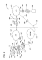
- Fig. 2 is a schematic diagram of example grid control system 100 that may be used with the generation and delivery system 10 (shown in Fig. 1 ).
- Grid control system 100 includes a plurality of locations 101.
- grid control system 100 monitors the delivery of energy from electric utility 12 to first customer location 16, second customer location 18, and third customer location 20.
- grid control system 100 includes any number of locations 101 that enables grid control system 100 to function as described herein.
- Grid control system includes a plurality of energy consumers 102.
- first location 16 includes at least one communication device 103 and at least one energy consumer 104 coupled to communication device 103.
- Second location 18 includes at least one communication device 106 and at least one energy consumer 108 coupled to communication device 106.
- Third location 20 includes at least one communication device 110 and at least one energy consumer 112 coupled to communication device 110.
- the term "couple" is not limited to a direct mechanical and/or electrical connection between components, but may also include an indirect mechanical and/or electrical connection between components.
- communication devices 103, 106, and 110 include a wired network adapter, a wireless network adapter, a mobile telecommunications adapter, and/or any other device that enables grid control system 100 to function as described herein.
- communication devices 103, 106, and 110 transmit and receive data, such as power management messages, between energy consumers 104, 108, and 112, respectively, and electric utility 12.
- energy consumer 102 is a device, such as appliances, machines, lighting systems, security systems, computer systems, and/or any other load that consumes energy received from electric utility 12.
- energy consumer 102 could include a washing machine, an air conditioning unit, a pool pump, and/or a heating unit.
- Grid control system 100 also includes a plurality of end user meters 46.
- communication device 103 is coupled to a first end user meter 114
- communication device 106 is coupled to a second end user meter 116
- communication device 110 is coupled to a third end user meter 118.
- grid control system 100 includes any number of end user meters 46 than enables grid control system 100 to function as described herein.
- energy consumer 104 is coupled to first meter 114 via communication device 103, energy consumer 108 is coupled to second meter 116 via communication device 106, and energy consumer 112 is coupled to third meter 118 via communication device 110.
- first location 16, second location 18, and third location 20 do not include communication devices 103, 106, and 110, respectively.
- energy consumer 104 is coupled directly to first meter 114, energy consumer 108 is coupled directly to second meter 116, and energy consumer 112 is coupled directly to third meter 118.
- first meter 114 measures the energy consumed by energy consumer 104
- second meter 116 measures the energy consumed by energy consumer 108
- third meter 118 measures the energy consumed by energy consumer 112.
- Meters 114, 116, and 118 transmit data representative of the energy consumed (hereinafter referred to as "energy consumption measurements") to an AMI network 120, as described more fully below.
- Each of the plurality of end user meters 46 may include, or be coupled to, a memory device 122.
- end user meters 46 are programmed to obtain energy consumption measurements at a start of a billing period and at an end of the billing period and to store energy consumption measurements within memory device 122.
- the billing period may be thirty days, a calendar month, and/or any other time period that allows grid control system 100 to function as described herein.
- end user meters 46 are enabled to measure and store energy consumption measurements periodically, such as every hour, every ten minutes, and/or at any other suitable frequency. End user meters 46 may also measure energy consumption upon a request (i.e., "on demand") submitted by, for example, electric utility 12.
- end user meters 46 are programmed to automatically transmit the energy consumption measurements to AMI network 120.
- AMI network 120 is located external to electric utility 12 and coupled in communication with a local area network (LAN) 123 at electric utility 12.
- AMI network 120 is located at the electric utility 12, such as within a data center (not shown) of electric utility 12.
- AMI network 120 receives energy consumption measurements from end user meters 46 and stores the energy consumption measurements in one or more data files within a memory device (neither shown).
- grid control system 100 includes a consumer region 124 and a utility company region 126.
- Consumer region 124 includes AMI network 120, end user meters 46, and locations 101.
- Locations 101 may each include a home area network (HAN).
- utility company region 126 includes electric utility 12 and LAN 123, which communicates with AMI network 120.
- LAN also communicates with at least one utility system 128.
- utility system 128 includes a user interface for use by a utility company operator (neither shown). Alternatively, utility system 128 may include any system that allows grid control system 100 to function as described herein.
- LAN 123 may also communicate with end user meters 46 via a public network 130.
- firewalls 132 are located between LAN 123 and AMI network 120, and between LAN 123 and utility system 128. Alternatively, firewalls 132 may be located at any location within grid control system 100 that enables grid control system 100 to function as described herein.
- energy consumers 104, 108, 112, meters 114, 116, and 118, AMI network 120, and LAN 123 each receive and transmit data between one another in a standard format.
- the format may be a proprietary vendor format or a format in accordance with a standard created by an industry consortium or standards development organization. Examples of such standards are International Electrotechnical Commission (IEC) 61850, IEC 61968, and ZigBee ®.
- the transmitted data includes a plurality of messages, and each message includes at least one packet.
- grid control system includes a plurality of communication paths 140 between components for use in transmitting messages between the components.
- the plurality of communication paths 140 may include a first communication path 141 between first location 16 and first meter 114, a second communication path 142 between second location 18 and second meter 116, a third communication path 143 between third meter 118 and AMI network 120, a fourth communication path 144 between AMI network 120 and LAN 123, a fifth communication path 145 between LAN 123 and utility system 128, a sixth communication path 146 between LAN 123 and public network 130, and a seventh communication path 147 between public network 130 and third meter 118.
- messages transmitted between components of grid control system 100 include data for use in controlling or adjusting operation of energy consumers and/or end user meters included in generation and delivery system 10, for example, energy consumer 102 and end user meter 46. More specifically, a message may be transmitted from end user meter 46 instructing energy consumer 102 to activate, deactivate, reduce power, and/or increase power. Moreover, a message may instruct energy consumer 102 to activate, deactivate, reduce power, and/or increase power for a predetermined duration of time. Further, a message may instruct end user meter 46 to connect or disconnect from grid control system 100. Moreover, a message may instruct end user meter 46 and/or energy consumer 102 to transmit energy consumption measurements at a given time and/or at a predetermined frequency. Alternatively, a message may instruct energy consumer 102 and/or end user meter 46 to perform any function that enables grid control system 100 to function as described herein.
- grid control system 100 includes at least one detection device 160.
- Detection device 160 intercepts and monitors messages transmitted via the plurality of communication paths 140. Detection device 160 may be coupled to any of plurality of communication paths 140.
- grid control system includes a first detection device 161 coupled to first communication path 141 and configured to monitor messages within first location 16, a second detection device 162 coupled to second communications path 142 and configured to monitor messages between second location 18 and second meter 116, a third detection device 163 coupled to third communication path 143 and configured to monitor messages between third meter 118 and AMI network 120, a fourth detection device 164 coupled to fourth communication path 144 and configured to monitor messages between AMI network 120 and LAN 123, a fifth detection device 165 coupled to fifth communication path 145 and configured to monitor messages between LAN 123 and utility system 128, a sixth detection device 166 coupled to sixth communication path 146 and configured to monitor messages between LAN 123 and public network 130, and a seventh detection device 167 coupled to seventh communication path 147 and
- Fig. 3 is a block diagram of detection device 160, which may be used with grid control system 100 (shown in Fig. 2 ).
- detection device 160 is separate from other components of grid control system 100.
- detection device 160 is included within at least one component of grid control system 100, such as energy consumer 102, and/or end user meter 46 (shown in Fig. 2 ).
- detection device 160 includes a memory device 310 and a processor 315 coupled to memory device 310 for executing instructions.
- executable instructions are stored in memory device 310.
- Detection device 160 is configured to perform one or more operations described herein by programming processor 315.
- processor 315 may be programmed by encoding an operation as one or more executable instructions and storing the executable instructions in memory device 310 and/or retrieving the executable instructions from memory device 310.
- processor 315 may include one or more processing units (e.g., in a multi-core configuration).
- Memory device 310 is one or more devices that enable information, such as executable instructions and/or other data, to be stored and retrieved.
- Memory device 310 may include one or more computer readable media, such as, without limitation, dynamic random access memory (DRAM), static random access memory (SRAM), a solid state disk, a hard disk, and/or any suitable memory that enables processor 315 to store, retrieve, and/or execute instructions and/or data.
- DRAM dynamic random access memory
- SRAM static random access memory
- Solid state disk such as, but not limited to store, retrieve, and/or execute instructions and/or data.
- Memory device 310 may be configured to store, without limitation, application source code, application object code, source code portions of interest, object code portions of interest, configuration data, execution events and/or any other type of data.
- detection device 160 includes a presentation interface 320 that is coupled to processor 315.
- Presentation interface 320 presents information, such as application source code and/or execution events, to a user 325.
- presentation interface 320 may include a display adapter (not shown in Fig. 3 ) that may be coupled to a display device, such as a cathode ray tube (CRT), a liquid crystal display (LCD), an organic LED (OLED) display, and/or an "electronic ink" display.
- presentation interface 320 includes one or more display devices.
- detection device 160 includes an input interface 330, such as a user input interface 335.
- user input interface 335 is coupled to processor 315 and receives input from user 325.
- User input interface 335 may include, for example, a keyboard, a pointing device, a mouse, a stylus, a touch sensitive panel (e.g., a touch pad or a touch screen), a gyroscope, an accelerometer, a position detector, and/or an audio user input interface.
- a single component, such as a touch screen may function as both a display device of presentation interface 320 and user input interface 335.
- detection device 160 includes at least one communication interface 340.
- Communication interface 340 is coupled to processor 315 and is configured to be coupled in communication with one or more remote devices or networks, such as energy consumer 102, end user meter 46, AMI network 120, and/or LAN 123.
- Communication interface 340 may include, without limitation, a wired network adapter, a wireless network adapter, and/or a mobile telecommunications adapter.
- Communication interface 340 transmits data to, and/or receives data from, one or more remote devices and/or networks, such as energy consumer 102, end user meter 46, AMI network 120, and/or LAN 123.
- detection device 160 receives and/or intercepts a message transmitted between components in grid control system 100, for example, a message transmitted from second location 18 to second meter 116.
- the message includes a plurality of packets.
- Processor 315 receives the plurality of packets and assembles the packets to form the message.
- processor 315 disassembles the message into packets and transmits the packets.
- detection device 160 may receive and transmit the entire message at once, without assembling the message from packets or disassembling the message into packets.
- detection device 160 determines whether the message transmitted over a communication path, for example second communication path 142, passes a rationality test.
- the rationality test determines whether the content of the transmitted message is rational or irrational. While messages may be transmitted in the correct format, the content of the transmitted messages may be erroneous and/or irrational. For example, a message may include an instruction for energy consumer 108 to deactivate for two hundred hours.
- the format of the transmitted message may be correct (specifying a duration of time for energy consumer 108 to deactivate), it is unlikely that the intended result is to actually deactivate energy consumer 108 for two hundred hours. Rather, the intent may have been to deactivate energy consumer 108 for two hours. Therefore, this intercepted message is referred to herein as irrational.
- memory device 310 stores a rationality database 350.
- Rationality database 350 includes at least one rule 352 that defines rational and/or irrational messages.
- Rational messages are transmitted messages that include instructions that cause a grid control system component, such as energy consumer 102 or end user meter 46, to perform a correct business function (e.g., deactivating energy consumer 102 for two hours), and irrational messages are transmitted messages that include instructions that cause a grid control system component to perform an incorrect business function (e.g. deactivating energy consumer 102 for two hundred hours).
- detection device 160 compares the message with rules 352 in rationality database 350.
- processor 315 is configured to compare the transmitted message with at least one rule 352 to determine whether the transmitted message is rational.
- Rules 352 in rationality database 350 may define rational and/or irrational messages in terms of permissible numbers of transactions between components in grid control system 100, durations of requests, and/or number of connects and/or disconnects for energy consumer 102 and/or end user meter 46.
- rules 352 may define rational and/or irrational messages in any suitable terms that enable detection device 160 to function as described herein.
- Rules 352 may specify threshold values that define whether a transmitted message is rational or irrational.
- rationality database 350 may include a rule that defines rational messages for deactivating energy consumer 102 as those transmitted messages that instruct energy consumer 102 to deactivate for a duration lasting no longer than five hours. Accordingly, if detection device 160 receives a transmitted message instructing energy consumer 102 to deactivate for two hundred hours, detection device 160 determines the transmitted message is irrational.
- Rules 352 may be input into rationality database 350 by user 325 using user input interface 335. Rules 352 may be user-defined and/or predefined. For example, user 325 may manipulate predefined rules 352 to create new rules. In an alternate embodiment, processor 315 generates rules 352 based on a volume of previously transmitted messages analyzed by detection device 160, and stores generated rules 352 in memory device 310. For example, after monitoring a plurality of messages instructing energy consumer 102 to deactivate for periods of time in a range of one to ten hours, processor 315 may generate a rule 352 that defines messages instructing energy consumer 102 to deactivate for more than two times an upper limit of previously received instructions (i.e., twenty hours).
- detection device 160 transmits the message to its intended destination. More specifically, processor 315 disassembles the message into packets and instructs communication interface 340 to transmit the message as packets to its intended destination. In the example embodiment, if the transmitted message is determined to be irrational, detection device 160 prohibits the message from being transmitted to its intended destination. Alternatively, detection device 160 may flag and/or identify the message as irrational and/or notify grid control system 100 that the message is irrational, but still transmit the message to its intended destination. Detection device 160 may notify grid control system 100 by generating and/or transmitting an alert signal.
- detection device 160 remedies the erroneous and/or irrational message, such that a message intercepted by detection device 160 and determined to be an irrational message is transmitted by detection device 160 as a rational message. For example, a message received at detection device 160 with instructions for deactivating energy consumer 102 for one-hundred hours and determined to be irrational may be transmitted from detection device 160 as a message that instructs energy consumer 102 to be deactivate for ten hours.
- Fig. 4 is a flowchart of an example method 400 for use in monitoring messages sent between components of a grid control system, for example, grid control system 100 (shown in Fig. 2 ).
- method 400 includes transmitting 402 at least one message from a first network component, for example, energy consumer 104 and/or a end user meter 46 (shown in Fig. 2 ) in grid control system 100, to a second network component, for example, energy consumer 104 and/or end user meter 46.
- Method 400 further includes intercepting 404 the message using a detection device, for example, detection device 160 (shown in Fig. 3 ).
- Method 400 further includes determining 406 a rationality of the transmitted message using the detection device 160.
- the method further includes processing 408 the transmitted message based at least in part on the determined rationality.
- the detection device, systems, and methods described herein facilitate preventing erroneous and/or irrational messages from being sent between components in a grid control system, even though the messages may be in an expected format. Furthermore, the detection device described herein may be positioned in numerous different locations within a power network and/or grid control system, facilitating identification of irrational messages sent between a plurality of components within the grid control system.
- the systems and methods described herein facilitate robust communications in an AMI system. More specifically, because the systems and methods described herein monitor the rationality of messages transmitted in the system, erroneous and/or irrational messages can be identified and dealt with accordingly. Further, the systems and methods described herein facilitate detecting erroneous and/or irrational messages at several different locations within the AMI system.
- Example embodiments of systems and methods for monitoring messages transmitted between components of a grid control system are described above in detail.
- the systems and methods are not limited to the specific embodiments described herein, but rather, components of the systems and/or steps of the methods may be utilized independently and separately from other components and/or steps described herein.
- the detection device described herein may also be used in combination with other energy systems and methods, and is not limited to practice with only the systems described herein. Rather, the example embodiment can be implemented and utilized in connection with many other utility and/or energy applications.
- the term "computer” refers to a system that includes at least one processor and at least one memory device.
- the processor may include any suitable programmable circuit including one or more systems and microcontrollers, microprocessors, reduced instruction set circuits (RISC), application specific integrated circuits (ASIC), programmable logic circuits (PLC), field programmable gate arrays (FPGA), and any other circuit capable of executing the functions described herein.
- RISC reduced instruction set circuits
- ASIC application specific integrated circuits
- PLC programmable logic circuits
- FPGA field programmable gate arrays
Abstract
A detection device (160) for monitoring at least one message transmitted between components included within a grid control system (100) is provided. The detection device includes a memory device (310) configured to store a rationality database (350) that includes at least one rule (352), and a processor (315) coupled to the memory device and configured to receive the at least one message and to compare the at least one message with the at least one rule to determine a rationality of the at least one message.
Description
- The present application relates generally to grid control systems and, more particularly, to a detection device, system, and method for use in monitoring messages exchanged by components included within a grid contsystem.
- Power generated by an electric utility is typically delivered to a customer via an electric grid. The power generation and delivery system is monitored and controlled by a grid control system. The grid control system generally includes a large number of individual subsystems, each of which may also include multiple components. Typically, information is received from many of the subsystems/components, and used to control operation of the electrical grid. For example, some power utilities utilize what is referred to herein as a "smart grid" or Advanced Metering Infrastructure (AMI) power network. Known AMI networks each include a plurality of subsystems that communicate with an operations subsystem that is typically located at the utility and remotely from the subsystems. Using an AMI network, a power utility may communicate with individual loads within a customer's premises and selectively reduce power consumption during peak usage periods. As such, a power utility may reduce power to low priority loads, while maintaining power to high priority loads.
- At least some known AMI networks receive and transmit data in a proprietary vendor format or in a format in accordance with a standard created by an industry consortium or standards development organization. Examples of such standards are International Electrotechnical Commission (IEC) 61850, IEC 61968, and ZigBee ®. ZigBee ® is a registered trademark of ZigBee Alliance, Inc., of San Ramon, CA. In some instances, data may be transmitted to a device in the correct format, but may instruct the device to perform an erroneous and/or irrational function. Instructions to perform an erroneous and/or irrational instruction may be the result of network tampering, or the result of component malfunction. A device component within the AMI network that performs an erroneous and/or irrational function may use excessive energy, create billing issues, cause physical damage, and/or inconvenience a customer and/or an energy provider.
- In one aspect, a detection device for monitoring at least one message transmitted between components included within a grid control system is provided. The detection device includes a memory device configured to store a rationality database that includes at least one rule, and a processor coupled to the memory device and configured to receive the at least one message and to compare the at least one message with the at least one rule to determine a rationality of the at least one message.
- In another aspect, a system for monitoring at least one message transmitted between components included within a grid control system is provided. The system includes a first network component, a second network component coupled to the first network component and configured to transmit the at least one message to the first network component, and a detection device configured to receive the at least one message from the second network component and to determine a rationality of the at least one message.
- In yet another aspect, a method for monitoring at least one message transmitted between a plurality of components within a grid control system is provided, the plurality of components including a first network component and a second network component. The method includes transmitting the at least one message from the first network component to the second network component, intercepting the at least one message using a detection device, and determining a rationality of the at least one message using the detection device.
-
-
Fig. 1 is a block diagram of an example power generation and delivery system. -
Fig. 2 is a schematic diagram of an electrical grid control system that may be used with the power generation and delivery system shown inFig. 1 . -
Fig. 3 is a block diagram of an example detection device that may be used with the electrical grid control system shown inFig. 2 . -
Fig. 4 is a flowchart of an example method for use in monitoring messages sent between components of the electrical grid control system shown inFig. 2 . - The systems and methods described herein facilitate enabling robust communications in an advanced metering infrastructure (AMI) system. More specifically, because the systems and methods described herein monitor the rationality of messages transmitted between components of the AMI system, erroneous and/or irrational messages can be identified and dealt with accordingly. Furthermore, the systems and methods described herein facilitate detecting erroneous and/or irrational messages at several different locations within the AMI system.
- Technical features of the methods and systems described herein include at least one of:
- (a) transmitting at least one message from a first network component to a second network component in a grid control system; (b) intercepting the at least one message using a detection device; and (c) determining a rationality of the at least one message using the detection device.
-
Fig. 1 is a block diagram of an example power generation anddelivery system 10. In the example embodiment, power generation anddelivery system 10 includes anelectric utility 12, anelectrical grid 14, and a plurality of customer or energy user locations, such as, afirst customer location 16, asecond customer location 18, and athird customer location 20.Customer locations electric utility 12. Although described herein as including three locations, power generation anddelivery system 10 may include any suitable number of locations that allows power generation anddelivery system 10 to function as described herein. - In the example embodiment, electricity is delivered from
electric utility 12 tocustomer locations electrical grid 14. In the example embodiment,electrical grid 14 includes at least onetransmission line 22, an electrical substation 24, and a plurality ofdistribution lines 26. Moreover, in the example embodiment,electric utility 12 includes an electricpower generation system 28 that supplies electrical power toelectrical grid 14. Electricpower generation system 28 may include a generator (not shown) driven by, for example, a gas turbine engine, a hydroelectric turbine, and/or a wind turbine (none shown). Alternatively, electricpower generation system 28 may utilize solar panels (not shown) and/or any other electricity generating device that enablessystem 10 to function as described herein. - In the example embodiment,
electric utility 12 also includes a distributioncontrol center substation 30 that controls energy production and delivery. Distributioncontrol center substation 30 is illustrated as being included withinelectric utility 12, but alternatively, distributioncontrol center substation 30 may be external to electric utility 12 (e.g., remotely located) and in communication withelectric utility 12. Furthermore, although described as including a computer system (not shown), distributioncontrol center substation 30 may include any suitable processing device that enables power generation anddelivery system 10 to function as described herein. The term processing device, as used herein, refers to central processing units, microprocessors, microcontrollers, reduced instruction set circuits (RISC), application specific integrated circuits (ASIC), logic circuits, and any other circuit or processor capable of executing the functions described herein. - In the example embodiment,
customer locations end user meter 46. In the example embodiment,end user meters 46 are part of an advanced metering infrastructure (AMI). AMI is an example of a bi-directional communication system that enableselectric utility 12 to measure and collect information relevant to energy usage fromcustomer locations user meter 46. Information may also be collected from other subsystems of electric power generation anddelivery system 10.Fig. 2 is a schematic diagram of examplegrid control system 100 that may be used with the generation and delivery system 10 (shown inFig. 1 ).Grid control system 100 includes a plurality oflocations 101. In the example embodiment,grid control system 100 monitors the delivery of energy fromelectric utility 12 tofirst customer location 16,second customer location 18, andthird customer location 20. Alternatively,grid control system 100 includes any number oflocations 101 that enablesgrid control system 100 to function as described herein. - Grid control system includes a plurality of
energy consumers 102. In the example embodiment,first location 16 includes at least onecommunication device 103 and at least oneenergy consumer 104 coupled tocommunication device 103.Second location 18 includes at least onecommunication device 106 and at least oneenergy consumer 108 coupled tocommunication device 106.Third location 20 includes at least onecommunication device 110 and at least oneenergy consumer 112 coupled tocommunication device 110. As used herein, the term "couple" is not limited to a direct mechanical and/or electrical connection between components, but may also include an indirect mechanical and/or electrical connection between components. In the example embodiment,communication devices grid control system 100 to function as described herein. For example,communication devices energy consumers electric utility 12. In the example embodiment,energy consumer 102 is a device, such as appliances, machines, lighting systems, security systems, computer systems, and/or any other load that consumes energy received fromelectric utility 12. For example,energy consumer 102 could include a washing machine, an air conditioning unit, a pool pump, and/or a heating unit. -
Grid control system 100 also includes a plurality ofend user meters 46. In the example embodiment,communication device 103 is coupled to a firstend user meter 114,communication device 106 is coupled to a secondend user meter 116, andcommunication device 110 is coupled to a thirdend user meter 118. Alternatively,grid control system 100 includes any number ofend user meters 46 than enablesgrid control system 100 to function as described herein. - In the example embodiment,
energy consumer 104 is coupled tofirst meter 114 viacommunication device 103,energy consumer 108 is coupled tosecond meter 116 viacommunication device 106, andenergy consumer 112 is coupled tothird meter 118 viacommunication device 110. In an alternative embodiment,first location 16,second location 18, andthird location 20 do not includecommunication devices energy consumer 104 is coupled directly tofirst meter 114,energy consumer 108 is coupled directly tosecond meter 116, andenergy consumer 112 is coupled directly tothird meter 118. In the example embodiment,first meter 114 measures the energy consumed byenergy consumer 104,second meter 116 measures the energy consumed byenergy consumer 108, andthird meter 118 measures the energy consumed byenergy consumer 112.Meters AMI network 120, as described more fully below. - Each of the plurality of
end user meters 46 may include, or be coupled to, amemory device 122. In the example embodiment,end user meters 46 are programmed to obtain energy consumption measurements at a start of a billing period and at an end of the billing period and to store energy consumption measurements withinmemory device 122. For example, the billing period may be thirty days, a calendar month, and/or any other time period that allowsgrid control system 100 to function as described herein. Moreover, in the example embodiment,end user meters 46 are enabled to measure and store energy consumption measurements periodically, such as every hour, every ten minutes, and/or at any other suitable frequency.End user meters 46 may also measure energy consumption upon a request (i.e., "on demand") submitted by, for example,electric utility 12. In the example embodiment,end user meters 46 are programmed to automatically transmit the energy consumption measurements toAMI network 120. - In the example embodiment,
AMI network 120 is located external toelectric utility 12 and coupled in communication with a local area network (LAN) 123 atelectric utility 12. Alternatively,AMI network 120 is located at theelectric utility 12, such as within a data center (not shown) ofelectric utility 12. In the example embodiment,AMI network 120 receives energy consumption measurements fromend user meters 46 and stores the energy consumption measurements in one or more data files within a memory device (neither shown). - In the example embodiment,
grid control system 100 includes aconsumer region 124 and autility company region 126.Consumer region 124 includesAMI network 120,end user meters 46, andlocations 101.Locations 101 may each include a home area network (HAN). In the example embodiment,utility company region 126 includeselectric utility 12 andLAN 123, which communicates withAMI network 120. LAN also communicates with at least oneutility system 128. In the example embodiment,utility system 128 includes a user interface for use by a utility company operator (neither shown). Alternatively,utility system 128 may include any system that allowsgrid control system 100 to function as described herein.LAN 123 may also communicate withend user meters 46 via apublic network 130. For security purposes, firewalls 132 are located betweenLAN 123 andAMI network 120, and betweenLAN 123 andutility system 128. Alternatively, firewalls 132 may be located at any location withingrid control system 100 that enablesgrid control system 100 to function as described herein. - In the example embodiment,
energy consumers meters AMI network 120, andLAN 123 each receive and transmit data between one another in a standard format. The format may be a proprietary vendor format or a format in accordance with a standard created by an industry consortium or standards development organization. Examples of such standards are International Electrotechnical Commission (IEC) 61850, IEC 61968, and ZigBee ®. The transmitted data includes a plurality of messages, and each message includes at least one packet. In the example embodiment, grid control system includes a plurality ofcommunication paths 140 between components for use in transmitting messages between the components. The plurality ofcommunication paths 140 may include afirst communication path 141 betweenfirst location 16 andfirst meter 114, asecond communication path 142 betweensecond location 18 andsecond meter 116, athird communication path 143 betweenthird meter 118 andAMI network 120, afourth communication path 144 betweenAMI network 120 andLAN 123, afifth communication path 145 betweenLAN 123 andutility system 128, asixth communication path 146 betweenLAN 123 andpublic network 130, and aseventh communication path 147 betweenpublic network 130 andthird meter 118. - In the example embodiment, messages transmitted between components of
grid control system 100 include data for use in controlling or adjusting operation of energy consumers and/or end user meters included in generation anddelivery system 10, for example,energy consumer 102 andend user meter 46. More specifically, a message may be transmitted fromend user meter 46 instructingenergy consumer 102 to activate, deactivate, reduce power, and/or increase power. Moreover, a message may instructenergy consumer 102 to activate, deactivate, reduce power, and/or increase power for a predetermined duration of time. Further, a message may instructend user meter 46 to connect or disconnect fromgrid control system 100. Moreover, a message may instructend user meter 46 and/orenergy consumer 102 to transmit energy consumption measurements at a given time and/or at a predetermined frequency. Alternatively, a message may instructenergy consumer 102 and/orend user meter 46 to perform any function that enablesgrid control system 100 to function as described herein. - In the example embodiment,
grid control system 100 includes at least onedetection device 160.Detection device 160 intercepts and monitors messages transmitted via the plurality ofcommunication paths 140.Detection device 160 may be coupled to any of plurality ofcommunication paths 140. In the example embodiment, grid control system includes afirst detection device 161 coupled tofirst communication path 141 and configured to monitor messages withinfirst location 16, asecond detection device 162 coupled tosecond communications path 142 and configured to monitor messages betweensecond location 18 andsecond meter 116, athird detection device 163 coupled tothird communication path 143 and configured to monitor messages betweenthird meter 118 andAMI network 120, afourth detection device 164 coupled tofourth communication path 144 and configured to monitor messages betweenAMI network 120 andLAN 123, afifth detection device 165 coupled tofifth communication path 145 and configured to monitor messages betweenLAN 123 andutility system 128, asixth detection device 166 coupled tosixth communication path 146 and configured to monitor messages betweenLAN 123 andpublic network 130, and aseventh detection device 167 coupled toseventh communication path 147 and configured to measure messages betweenpublic network 130 andthird meter 118. Alternatively,detection device 160 may be coupled to anycommunication path 140 and monitor any message transmitted ingrid control system 100 that enablesgrid control system 100 to function as described herein. -
Fig. 3 is a block diagram ofdetection device 160, which may be used with grid control system 100 (shown inFig. 2 ). In the example embodiment,detection device 160 is separate from other components ofgrid control system 100. In an alternative embodiment,detection device 160 is included within at least one component ofgrid control system 100, such asenergy consumer 102, and/or end user meter 46 (shown inFig. 2 ). In the example embodiment,detection device 160 includes amemory device 310 and aprocessor 315 coupled tomemory device 310 for executing instructions. In some embodiments, executable instructions are stored inmemory device 310.Detection device 160 is configured to perform one or more operations described herein byprogramming processor 315. For example,processor 315 may be programmed by encoding an operation as one or more executable instructions and storing the executable instructions inmemory device 310 and/or retrieving the executable instructions frommemory device 310. In one embodiment,processor 315 may include one or more processing units (e.g., in a multi-core configuration). -
Memory device 310 is one or more devices that enable information, such as executable instructions and/or other data, to be stored and retrieved.Memory device 310 may include one or more computer readable media, such as, without limitation, dynamic random access memory (DRAM), static random access memory (SRAM), a solid state disk, a hard disk, and/or any suitable memory that enablesprocessor 315 to store, retrieve, and/or execute instructions and/or data..Memory device 310 may be configured to store, without limitation, application source code, application object code, source code portions of interest, object code portions of interest, configuration data, execution events and/or any other type of data. - In the example embodiment,
detection device 160 includes apresentation interface 320 that is coupled toprocessor 315.Presentation interface 320 presents information, such as application source code and/or execution events, to auser 325. For example,presentation interface 320 may include a display adapter (not shown inFig. 3 ) that may be coupled to a display device, such as a cathode ray tube (CRT), a liquid crystal display (LCD), an organic LED (OLED) display, and/or an "electronic ink" display. In some embodiments,presentation interface 320 includes one or more display devices. - Moreover, in the example embodiment,
detection device 160 includes aninput interface 330, such as auser input interface 335. In the example embodiment,user input interface 335 is coupled toprocessor 315 and receives input fromuser 325.User input interface 335 may include, for example, a keyboard, a pointing device, a mouse, a stylus, a touch sensitive panel (e.g., a touch pad or a touch screen), a gyroscope, an accelerometer, a position detector, and/or an audio user input interface. A single component, such as a touch screen, may function as both a display device ofpresentation interface 320 anduser input interface 335. - In the example embodiment,
detection device 160 includes at least onecommunication interface 340.Communication interface 340 is coupled toprocessor 315 and is configured to be coupled in communication with one or more remote devices or networks, such asenergy consumer 102,end user meter 46,AMI network 120, and/orLAN 123.Communication interface 340 may include, without limitation, a wired network adapter, a wireless network adapter, and/or a mobile telecommunications adapter.Communication interface 340 transmits data to, and/or receives data from, one or more remote devices and/or networks, such asenergy consumer 102,end user meter 46,AMI network 120, and/orLAN 123. - In the example embodiment,
detection device 160 receives and/or intercepts a message transmitted between components ingrid control system 100, for example, a message transmitted fromsecond location 18 tosecond meter 116. The message includes a plurality of packets.Processor 315 receives the plurality of packets and assembles the packets to form the message. Similarly, whendetection device 160 sends a message,processor 315 disassembles the message into packets and transmits the packets. Alternatively,detection device 160 may receive and transmit the entire message at once, without assembling the message from packets or disassembling the message into packets. - In the example embodiment, referring to
Figs. 2 and3 , after receiving and/or intercepting the message,detection device 160, and more specificallyprocessor 315, determines whether the message transmitted over a communication path, for examplesecond communication path 142, passes a rationality test. The rationality test determines whether the content of the transmitted message is rational or irrational. While messages may be transmitted in the correct format, the content of the transmitted messages may be erroneous and/or irrational. For example, a message may include an instruction forenergy consumer 108 to deactivate for two hundred hours. While the format of the transmitted message may be correct (specifying a duration of time forenergy consumer 108 to deactivate), it is unlikely that the intended result is to actually deactivateenergy consumer 108 for two hundred hours. Rather, the intent may have been to deactivateenergy consumer 108 for two hours. Therefore, this intercepted message is referred to herein as irrational. - To detect such erroneous and/or irrational messages and/or instructions, in the example embodiment,
memory device 310 stores arationality database 350.Rationality database 350 includes at least onerule 352 that defines rational and/or irrational messages. Rational messages are transmitted messages that include instructions that cause a grid control system component, such asenergy consumer 102 orend user meter 46, to perform a correct business function (e.g., deactivatingenergy consumer 102 for two hours), and irrational messages are transmitted messages that include instructions that cause a grid control system component to perform an incorrect business function (e.g. deactivatingenergy consumer 102 for two hundred hours). - To determine whether the transmitted message is rational or irrational,
detection device 160 compares the message withrules 352 inrationality database 350. Accordingly,processor 315 is configured to compare the transmitted message with at least onerule 352 to determine whether the transmitted message is rational.Rules 352 inrationality database 350 may define rational and/or irrational messages in terms of permissible numbers of transactions between components ingrid control system 100, durations of requests, and/or number of connects and/or disconnects forenergy consumer 102 and/orend user meter 46. Alternatively, rules 352 may define rational and/or irrational messages in any suitable terms that enabledetection device 160 to function as described herein. -
Rules 352 may specify threshold values that define whether a transmitted message is rational or irrational. For example,rationality database 350 may include a rule that defines rational messages for deactivatingenergy consumer 102 as those transmitted messages that instructenergy consumer 102 to deactivate for a duration lasting no longer than five hours. Accordingly, ifdetection device 160 receives a transmitted message instructingenergy consumer 102 to deactivate for two hundred hours,detection device 160 determines the transmitted message is irrational. -
Rules 352 may be input intorationality database 350 byuser 325 usinguser input interface 335.Rules 352 may be user-defined and/or predefined. For example,user 325 may manipulatepredefined rules 352 to create new rules. In an alternate embodiment,processor 315 generatesrules 352 based on a volume of previously transmitted messages analyzed bydetection device 160, and stores generatedrules 352 inmemory device 310. For example, after monitoring a plurality of messages instructingenergy consumer 102 to deactivate for periods of time in a range of one to ten hours,processor 315 may generate arule 352 that defines messages instructingenergy consumer 102 to deactivate for more than two times an upper limit of previously received instructions (i.e., twenty hours). - In the example embodiment, if the transmitted message is determined to be rational by
detection device 160,detection device 160 transmits the message to its intended destination. More specifically,processor 315 disassembles the message into packets and instructscommunication interface 340 to transmit the message as packets to its intended destination. In the example embodiment, if the transmitted message is determined to be irrational,detection device 160 prohibits the message from being transmitted to its intended destination. Alternatively,detection device 160 may flag and/or identify the message as irrational and/or notifygrid control system 100 that the message is irrational, but still transmit the message to its intended destination.Detection device 160 may notifygrid control system 100 by generating and/or transmitting an alert signal. Moreover, in some embodiments,detection device 160 remedies the erroneous and/or irrational message, such that a message intercepted bydetection device 160 and determined to be an irrational message is transmitted bydetection device 160 as a rational message. For example, a message received atdetection device 160 with instructions for deactivatingenergy consumer 102 for one-hundred hours and determined to be irrational may be transmitted fromdetection device 160 as a message that instructsenergy consumer 102 to be deactivate for ten hours. -
Fig. 4 is a flowchart of anexample method 400 for use in monitoring messages sent between components of a grid control system, for example, grid control system 100 (shown inFig. 2 ). In the example embodiment,method 400 includes transmitting 402 at least one message from a first network component, for example,energy consumer 104 and/or a end user meter 46 (shown inFig. 2 ) ingrid control system 100, to a second network component, for example,energy consumer 104 and/orend user meter 46.Method 400 further includes intercepting 404 the message using a detection device, for example, detection device 160 (shown inFig. 3 ).Method 400 further includes determining 406 a rationality of the transmitted message using thedetection device 160. The method further includes processing 408 the transmitted message based at least in part on the determined rationality. - The detection device, systems, and methods described herein facilitate preventing erroneous and/or irrational messages from being sent between components in a grid control system, even though the messages may be in an expected format. Furthermore, the detection device described herein may be positioned in numerous different locations within a power network and/or grid control system, facilitating identification of irrational messages sent between a plurality of components within the grid control system.
- The systems and methods described herein facilitate robust communications in an AMI system. More specifically, because the systems and methods described herein monitor the rationality of messages transmitted in the system, erroneous and/or irrational messages can be identified and dealt with accordingly. Further, the systems and methods described herein facilitate detecting erroneous and/or irrational messages at several different locations within the AMI system.
- Example embodiments of systems and methods for monitoring messages transmitted between components of a grid control system are described above in detail. The systems and methods are not limited to the specific embodiments described herein, but rather, components of the systems and/or steps of the methods may be utilized independently and separately from other components and/or steps described herein. For example, the detection device described herein may also be used in combination with other energy systems and methods, and is not limited to practice with only the systems described herein. Rather, the example embodiment can be implemented and utilized in connection with many other utility and/or energy applications.
- As used herein, the term "computer" refers to a system that includes at least one processor and at least one memory device. The processor may include any suitable programmable circuit including one or more systems and microcontrollers, microprocessors, reduced instruction set circuits (RISC), application specific integrated circuits (ASIC), programmable logic circuits (PLC), field programmable gate arrays (FPGA), and any other circuit capable of executing the functions described herein. The above represent examples only, and thus are not intended to limit in any way the definition and/or meaning of the term "processor."
- Although specific features of various embodiments of the invention may be shown in some drawings and not in others, this is for convenience only. In accordance with the principles of the invention, any feature of a drawing may be referenced and/or claimed in combination with any feature of any other drawing.
- This written description uses examples to disclose the invention, including the best mode, and also to enable any person skilled in the art to practice the invention, including making and using any devices or systems and performing any incorporated methods. The patentable scope of the invention is defined by the claims, and may include other examples that occur to those skilled in the art. Such other examples are intended to be within the scope of the claims if they have structural elements that do not differ from the literal language of the claims, or if they include equivalent structural elements with insubstantial differences from the literal language of the claims.
Claims (15)
- A detection device (160) for monitoring at least one message transmitted between components included within a grid control system (100), said detection device comprising:a memory device (310) configured to store a rationality database (350) that includes at least one rule (352); anda processor (315) coupled to said memory device and configured to receive the at least one message and to compare the at least one message with said at least one rule to determine a rationality of the at least one message.
- A detection device (160) in accordance with Claim 1, wherein said at least one rule (352) defines at least one of a rational and an irrational message.
- A detection device (160) in accordance with Claim 1 or Claim 2, wherein said processor (315) is further configured to generate said at least one rule (352) based on a plurality of previously transmitted messages.
- A detection device (160) in accordance with Claim 1, 2 or 3, wherein said detection device is included within at least one component within the grid control system (100).
- A detection device (160) in accordance with any one of Claims 1 to 4, wherein said at least one component comprises one of an energy consumer (102, 104, 108, 112), a meter (114, 116, 118), a component of an advanced metering infrastructure (AMI) network (120), and a component of a local area network (LAN) (123).
- A detection device (160) in accordance with any one of Claims 1 to 5, wherein said processor (315) is configured to prevent transmission of the at least one message when said processor determines the at least one message is irrational.
- A detection device (160) in accordance with any one of Claims 1 to 6, wherein said processor (315) is configured to generate an alert signal when said processor determines the at least one message is irrational.
- A system for monitoring at least one message transmitted between components included within a grid control system (100), said system comprising:a first network component;a second network component coupled to said first network component and configured to transmit the at least one message to said first network component; anda detection device (160) configured to receive the at least one message from said second network component and to determine a rationality of the at least one message.
- A system in accordance with Claim 8, wherein said detection device (160) is at least one of included within at least one of said first network component and said second network component and coupled between said first network component and said second network component.
- A system in accordance with Claim 8 or Claim 9, wherein at least one of said first network component and said second network component comprises one of an energy consumer (102, 104, 108, 112), a meter (114, 116, 118), a component of an advanced metering infrastructure (AMI) network (120), and a component of a local area network (LAN) (123).
- A system in accordance with Claim 8, 9 or 10, wherein said detection device (160) is configured to prevent transmission of the at least one message to said first network component when said detection device determines the at least one message is irrational.
- A system in accordance with any one of Claims 8 to 11, wherein said detection device (160) is configured to generate an alert signal when said detection device determines the at least one message is irrational.
- A system in accordance with any one of Claims 8 to 12, wherein said detection device (160) is configured to determine the rationality of the at least one message based on at least one rule.
- A system in accordance with Claim 13, said detection device (160) in accordance with any one of claims 1 to 7.
- A method for monitoring at least one message transmitted between a plurality of components within a grid control system (100), the plurality of components including a first network component and a second network component, said method comprising:transmitting the at least one message from the first network component to the second network component;intercepting the at least one message using a detection device (160); anddetermining a rationality of the at least one message using the detection device (160).
Applications Claiming Priority (1)
| Application Number | Priority Date | Filing Date | Title |
|---|---|---|---|
| US13/089,869 US20120268289A1 (en) | 2011-04-19 | 2011-04-19 | Methods and systems for monitoring a grid control system |
Publications (1)
| Publication Number | Publication Date |
|---|---|
| EP2515083A1 true EP2515083A1 (en) | 2012-10-24 |
Family
ID=46085362
Family Applications (1)
| Application Number | Title | Priority Date | Filing Date |
|---|---|---|---|
| EP12164445A Withdrawn EP2515083A1 (en) | 2011-04-19 | 2012-04-17 | Methods and systems for monitoring a grid control system |
Country Status (3)
| Country | Link |
|---|---|
| US (1) | US20120268289A1 (en) |
| EP (1) | EP2515083A1 (en) |
| CN (1) | CN102752168A (en) |
Citations (6)
| Publication number | Priority date | Publication date | Assignee | Title |
|---|---|---|---|---|
| US20020012323A1 (en) * | 1999-03-18 | 2002-01-31 | Petite Thomas D. | Systems and methods for enabling a mobile user to notify an automated monitoring system of an emergency situation |
| EP1420548A2 (en) * | 2002-11-18 | 2004-05-19 | Texas Instruments Inc. | Expert system for protocols analysis |
| US20050206530A1 (en) * | 2004-03-18 | 2005-09-22 | Cumming Daniel A | Solar powered radio frequency device within an energy sensor system |
| US20070013547A1 (en) * | 2003-02-14 | 2007-01-18 | Boaz Jon A | Automated meter reading system, communication and control network from automated meter reading, meter data collector, and associated methods |
| US20100188260A1 (en) * | 2009-04-20 | 2010-07-29 | Itron, Inc. | Endpoint classification and command processing |
| WO2011156776A2 (en) * | 2010-06-10 | 2011-12-15 | The Regents Of The University Of California | Smart electric vehicle (ev) charging and grid integration apparatus and methods |
Family Cites Families (7)
| Publication number | Priority date | Publication date | Assignee | Title |
|---|---|---|---|---|
| US4322842A (en) * | 1979-10-23 | 1982-03-30 | Altran Electronics | Broadcast system for distribution automation and remote metering |
| DE10141092A1 (en) * | 2001-08-22 | 2003-03-06 | Siemens Ag | Method for the transmission of data packets in a radio communication system |
| US7382795B2 (en) * | 2004-04-14 | 2008-06-03 | International Business Machines Corporation | Mechanism for validating the message format for message channels |
| WO2009001337A2 (en) * | 2007-06-22 | 2008-12-31 | Medingo Ltd. | Communications for medicinal fluid delivery system |
| US8332704B2 (en) * | 2008-03-14 | 2012-12-11 | Samsung Electronics Co., Ltd. | Apparatus and method for supporting automatic retransmission request (ARQ) in a wireless relay communication system |
| US8275890B2 (en) * | 2009-06-03 | 2012-09-25 | International Business Machines Corporation | Detecting an inactive client during a communication session |
| US20100315263A1 (en) * | 2009-06-16 | 2010-12-16 | Elster Electricity, Llc | Converting ac powered utility meter to solar powered meter |
-
2011
- 2011-04-19 US US13/089,869 patent/US20120268289A1/en not_active Abandoned
-
2012
- 2012-04-17 EP EP12164445A patent/EP2515083A1/en not_active Withdrawn
- 2012-04-19 CN CN2012102054774A patent/CN102752168A/en active Pending
Patent Citations (6)
| Publication number | Priority date | Publication date | Assignee | Title |
|---|---|---|---|---|
| US20020012323A1 (en) * | 1999-03-18 | 2002-01-31 | Petite Thomas D. | Systems and methods for enabling a mobile user to notify an automated monitoring system of an emergency situation |
| EP1420548A2 (en) * | 2002-11-18 | 2004-05-19 | Texas Instruments Inc. | Expert system for protocols analysis |
| US20070013547A1 (en) * | 2003-02-14 | 2007-01-18 | Boaz Jon A | Automated meter reading system, communication and control network from automated meter reading, meter data collector, and associated methods |
| US20050206530A1 (en) * | 2004-03-18 | 2005-09-22 | Cumming Daniel A | Solar powered radio frequency device within an energy sensor system |
| US20100188260A1 (en) * | 2009-04-20 | 2010-07-29 | Itron, Inc. | Endpoint classification and command processing |
| WO2011156776A2 (en) * | 2010-06-10 | 2011-12-15 | The Regents Of The University Of California | Smart electric vehicle (ev) charging and grid integration apparatus and methods |
Also Published As
| Publication number | Publication date |
|---|---|
| CN102752168A (en) | 2012-10-24 |
| US20120268289A1 (en) | 2012-10-25 |
Similar Documents
| Publication | Publication Date | Title |
|---|---|---|
| US9021431B2 (en) | System and method for developing, deploying and implementing power system computer applications | |
| EP2096416B1 (en) | Management platform and associated method for managing smart meters | |
| US8949050B2 (en) | Smartgrid energy-usage-data storage and presentation systems, devices, protocol, and processes including a visualization, and load fingerprinting process | |
| EP2515085A2 (en) | Systems and method for transmitting data in an advanced metering infrastructure | |
| US20160109495A1 (en) | System and method for analyzing and monitoring smart meter network communications | |
| EP2795855B1 (en) | System and method for using a network to control a power management system | |
| JP2012244631A (en) | Head-end system for advanced metering infrastructure network | |
| US10412200B2 (en) | Reconfigurable extended communication interface devices for monitoring and control of power system devices | |
| De Capua et al. | A smart energy meter for power grids | |
| CN116482598A (en) | Power consumption data monitoring method and device | |
| KR20120071170A (en) | System and method for energy managing service | |
| AU2013387635A1 (en) | Apparatus and method for interfacing with supervisory monitoring and control arrangements | |
| US7991567B1 (en) | Centralized operating meter for energy technologies | |
| CN109244762A (en) | A kind of socket and electric quantity managing method with electricity statistical function | |
| US9047757B2 (en) | Systems and methods for remotely controlling an advanced metering infrastructure | |
| US9125010B2 (en) | Systems and methods to implement demand response events | |
| EP2515083A1 (en) | Methods and systems for monitoring a grid control system | |
| JP6816962B2 (en) | Power monitor, display control method and display control program | |
| JP6277479B2 (en) | Registration system | |
| CN205583848U (en) | Intelligent ammeter cabinet | |
| US20130116838A1 (en) | System and device for utility management | |
| KR20200077761A (en) | System and method for managing photovoltaic power generation equipment | |
| AU2020284174B2 (en) | Distributed energy resource registration | |
| KR102083144B1 (en) | Intelligent power meter modem | |
| CN113742017A (en) | Display method and device of power data, storage medium and electronic equipment |
Legal Events
| Date | Code | Title | Description |
|---|---|---|---|
| PUAI | Public reference made under article 153(3) epc to a published international application that has entered the european phase |
Free format text: ORIGINAL CODE: 0009012 |
|
| AK | Designated contracting states |
Kind code of ref document: A1 Designated state(s): AL AT BE BG CH CY CZ DE DK EE ES FI FR GB GR HR HU IE IS IT LI LT LU LV MC MK MT NL NO PL PT RO RS SE SI SK SM TR |
|
| AX | Request for extension of the european patent |
Extension state: BA ME |
|
| 17P | Request for examination filed |
Effective date: 20130424 |
|
| STAA | Information on the status of an ep patent application or granted ep patent |
Free format text: STATUS: THE APPLICATION IS DEEMED TO BE WITHDRAWN |
|
| 18D | Application deemed to be withdrawn |
Effective date: 20151103 |