EP2522310A1 - Mould for producing spacers for endoprosthetics - Google Patents
Mould for producing spacers for endoprosthetics Download PDFInfo
- Publication number
- EP2522310A1 EP2522310A1 EP12003586A EP12003586A EP2522310A1 EP 2522310 A1 EP2522310 A1 EP 2522310A1 EP 12003586 A EP12003586 A EP 12003586A EP 12003586 A EP12003586 A EP 12003586A EP 2522310 A1 EP2522310 A1 EP 2522310A1
- Authority
- EP
- European Patent Office
- Prior art keywords
- mold
- elements
- part form
- partial
- mold according
- Prior art date
- Legal status (The legal status is an assumption and is not a legal conclusion. Google has not performed a legal analysis and makes no representation as to the accuracy of the status listed.)
- Granted
Links
Images

Classifications
-
- A—HUMAN NECESSITIES
- A61—MEDICAL OR VETERINARY SCIENCE; HYGIENE
- A61F—FILTERS IMPLANTABLE INTO BLOOD VESSELS; PROSTHESES; DEVICES PROVIDING PATENCY TO, OR PREVENTING COLLAPSING OF, TUBULAR STRUCTURES OF THE BODY, e.g. STENTS; ORTHOPAEDIC, NURSING OR CONTRACEPTIVE DEVICES; FOMENTATION; TREATMENT OR PROTECTION OF EYES OR EARS; BANDAGES, DRESSINGS OR ABSORBENT PADS; FIRST-AID KITS
- A61F2/00—Filters implantable into blood vessels; Prostheses, i.e. artificial substitutes or replacements for parts of the body; Appliances for connecting them with the body; Devices providing patency to, or preventing collapsing of, tubular structures of the body, e.g. stents
- A61F2/02—Prostheses implantable into the body
- A61F2/30—Joints
- A61F2/3094—Designing or manufacturing processes
- A61F2/30942—Designing or manufacturing processes for designing or making customized prostheses, e.g. using templates, CT or NMR scans, finite-element analysis or CAD-CAM techniques
-
- A—HUMAN NECESSITIES
- A61—MEDICAL OR VETERINARY SCIENCE; HYGIENE
- A61F—FILTERS IMPLANTABLE INTO BLOOD VESSELS; PROSTHESES; DEVICES PROVIDING PATENCY TO, OR PREVENTING COLLAPSING OF, TUBULAR STRUCTURES OF THE BODY, e.g. STENTS; ORTHOPAEDIC, NURSING OR CONTRACEPTIVE DEVICES; FOMENTATION; TREATMENT OR PROTECTION OF EYES OR EARS; BANDAGES, DRESSINGS OR ABSORBENT PADS; FIRST-AID KITS
- A61F2/00—Filters implantable into blood vessels; Prostheses, i.e. artificial substitutes or replacements for parts of the body; Appliances for connecting them with the body; Devices providing patency to, or preventing collapsing of, tubular structures of the body, e.g. stents
- A61F2/02—Prostheses implantable into the body
- A61F2/30—Joints
- A61F2/32—Joints for the hip
- A61F2/36—Femoral heads ; Femoral endoprostheses
-
- A—HUMAN NECESSITIES
- A61—MEDICAL OR VETERINARY SCIENCE; HYGIENE
- A61F—FILTERS IMPLANTABLE INTO BLOOD VESSELS; PROSTHESES; DEVICES PROVIDING PATENCY TO, OR PREVENTING COLLAPSING OF, TUBULAR STRUCTURES OF THE BODY, e.g. STENTS; ORTHOPAEDIC, NURSING OR CONTRACEPTIVE DEVICES; FOMENTATION; TREATMENT OR PROTECTION OF EYES OR EARS; BANDAGES, DRESSINGS OR ABSORBENT PADS; FIRST-AID KITS
- A61F2/00—Filters implantable into blood vessels; Prostheses, i.e. artificial substitutes or replacements for parts of the body; Appliances for connecting them with the body; Devices providing patency to, or preventing collapsing of, tubular structures of the body, e.g. stents
- A61F2/02—Prostheses implantable into the body
- A61F2/30—Joints
- A61F2/3094—Designing or manufacturing processes
-
- A—HUMAN NECESSITIES
- A61—MEDICAL OR VETERINARY SCIENCE; HYGIENE
- A61F—FILTERS IMPLANTABLE INTO BLOOD VESSELS; PROSTHESES; DEVICES PROVIDING PATENCY TO, OR PREVENTING COLLAPSING OF, TUBULAR STRUCTURES OF THE BODY, e.g. STENTS; ORTHOPAEDIC, NURSING OR CONTRACEPTIVE DEVICES; FOMENTATION; TREATMENT OR PROTECTION OF EYES OR EARS; BANDAGES, DRESSINGS OR ABSORBENT PADS; FIRST-AID KITS
- A61F2/00—Filters implantable into blood vessels; Prostheses, i.e. artificial substitutes or replacements for parts of the body; Appliances for connecting them with the body; Devices providing patency to, or preventing collapsing of, tubular structures of the body, e.g. stents
- A61F2/02—Prostheses implantable into the body
- A61F2/30—Joints
- A61F2002/30001—Additional features of subject-matter classified in A61F2/28, A61F2/30 and subgroups thereof
- A61F2002/30316—The prosthesis having different structural features at different locations within the same prosthesis; Connections between prosthetic parts; Special structural features of bone or joint prostheses not otherwise provided for
- A61F2002/30329—Connections or couplings between prosthetic parts, e.g. between modular parts; Connecting elements
- A61F2002/30331—Connections or couplings between prosthetic parts, e.g. between modular parts; Connecting elements made by longitudinally pushing a protrusion into a complementarily-shaped recess, e.g. held by friction fit
-
- A—HUMAN NECESSITIES
- A61—MEDICAL OR VETERINARY SCIENCE; HYGIENE
- A61F—FILTERS IMPLANTABLE INTO BLOOD VESSELS; PROSTHESES; DEVICES PROVIDING PATENCY TO, OR PREVENTING COLLAPSING OF, TUBULAR STRUCTURES OF THE BODY, e.g. STENTS; ORTHOPAEDIC, NURSING OR CONTRACEPTIVE DEVICES; FOMENTATION; TREATMENT OR PROTECTION OF EYES OR EARS; BANDAGES, DRESSINGS OR ABSORBENT PADS; FIRST-AID KITS
- A61F2/00—Filters implantable into blood vessels; Prostheses, i.e. artificial substitutes or replacements for parts of the body; Appliances for connecting them with the body; Devices providing patency to, or preventing collapsing of, tubular structures of the body, e.g. stents
- A61F2/02—Prostheses implantable into the body
- A61F2/30—Joints
- A61F2002/30001—Additional features of subject-matter classified in A61F2/28, A61F2/30 and subgroups thereof
- A61F2002/30316—The prosthesis having different structural features at different locations within the same prosthesis; Connections between prosthetic parts; Special structural features of bone or joint prostheses not otherwise provided for
- A61F2002/30329—Connections or couplings between prosthetic parts, e.g. between modular parts; Connecting elements
- A61F2002/30476—Connections or couplings between prosthetic parts, e.g. between modular parts; Connecting elements locked by an additional locking mechanism
- A61F2002/305—Snap connection
-
- A—HUMAN NECESSITIES
- A61—MEDICAL OR VETERINARY SCIENCE; HYGIENE
- A61F—FILTERS IMPLANTABLE INTO BLOOD VESSELS; PROSTHESES; DEVICES PROVIDING PATENCY TO, OR PREVENTING COLLAPSING OF, TUBULAR STRUCTURES OF THE BODY, e.g. STENTS; ORTHOPAEDIC, NURSING OR CONTRACEPTIVE DEVICES; FOMENTATION; TREATMENT OR PROTECTION OF EYES OR EARS; BANDAGES, DRESSINGS OR ABSORBENT PADS; FIRST-AID KITS
- A61F2/00—Filters implantable into blood vessels; Prostheses, i.e. artificial substitutes or replacements for parts of the body; Appliances for connecting them with the body; Devices providing patency to, or preventing collapsing of, tubular structures of the body, e.g. stents
- A61F2/02—Prostheses implantable into the body
- A61F2/30—Joints
- A61F2002/30001—Additional features of subject-matter classified in A61F2/28, A61F2/30 and subgroups thereof
- A61F2002/30316—The prosthesis having different structural features at different locations within the same prosthesis; Connections between prosthetic parts; Special structural features of bone or joint prostheses not otherwise provided for
- A61F2002/30535—Special structural features of bone or joint prostheses not otherwise provided for
- A61F2002/30604—Special structural features of bone or joint prostheses not otherwise provided for modular
-
- A—HUMAN NECESSITIES
- A61—MEDICAL OR VETERINARY SCIENCE; HYGIENE
- A61F—FILTERS IMPLANTABLE INTO BLOOD VESSELS; PROSTHESES; DEVICES PROVIDING PATENCY TO, OR PREVENTING COLLAPSING OF, TUBULAR STRUCTURES OF THE BODY, e.g. STENTS; ORTHOPAEDIC, NURSING OR CONTRACEPTIVE DEVICES; FOMENTATION; TREATMENT OR PROTECTION OF EYES OR EARS; BANDAGES, DRESSINGS OR ABSORBENT PADS; FIRST-AID KITS
- A61F2/00—Filters implantable into blood vessels; Prostheses, i.e. artificial substitutes or replacements for parts of the body; Appliances for connecting them with the body; Devices providing patency to, or preventing collapsing of, tubular structures of the body, e.g. stents
- A61F2/02—Prostheses implantable into the body
- A61F2/30—Joints
- A61F2002/30001—Additional features of subject-matter classified in A61F2/28, A61F2/30 and subgroups thereof
- A61F2002/30667—Features concerning an interaction with the environment or a particular use of the prosthesis
- A61F2002/30672—Features concerning an interaction with the environment or a particular use of the prosthesis temporary
-
- A—HUMAN NECESSITIES
- A61—MEDICAL OR VETERINARY SCIENCE; HYGIENE
- A61F—FILTERS IMPLANTABLE INTO BLOOD VESSELS; PROSTHESES; DEVICES PROVIDING PATENCY TO, OR PREVENTING COLLAPSING OF, TUBULAR STRUCTURES OF THE BODY, e.g. STENTS; ORTHOPAEDIC, NURSING OR CONTRACEPTIVE DEVICES; FOMENTATION; TREATMENT OR PROTECTION OF EYES OR EARS; BANDAGES, DRESSINGS OR ABSORBENT PADS; FIRST-AID KITS
- A61F2/00—Filters implantable into blood vessels; Prostheses, i.e. artificial substitutes or replacements for parts of the body; Appliances for connecting them with the body; Devices providing patency to, or preventing collapsing of, tubular structures of the body, e.g. stents
- A61F2/02—Prostheses implantable into the body
- A61F2/30—Joints
- A61F2/3094—Designing or manufacturing processes
- A61F2/30942—Designing or manufacturing processes for designing or making customized prostheses, e.g. using templates, CT or NMR scans, finite-element analysis or CAD-CAM techniques
- A61F2002/30957—Designing or manufacturing processes for designing or making customized prostheses, e.g. using templates, CT or NMR scans, finite-element analysis or CAD-CAM techniques using a positive or a negative model, e.g. moulds
-
- A—HUMAN NECESSITIES
- A61—MEDICAL OR VETERINARY SCIENCE; HYGIENE
- A61F—FILTERS IMPLANTABLE INTO BLOOD VESSELS; PROSTHESES; DEVICES PROVIDING PATENCY TO, OR PREVENTING COLLAPSING OF, TUBULAR STRUCTURES OF THE BODY, e.g. STENTS; ORTHOPAEDIC, NURSING OR CONTRACEPTIVE DEVICES; FOMENTATION; TREATMENT OR PROTECTION OF EYES OR EARS; BANDAGES, DRESSINGS OR ABSORBENT PADS; FIRST-AID KITS
- A61F2310/00—Prostheses classified in A61F2/28 or A61F2/30 - A61F2/44 being constructed from or coated with a particular material
- A61F2310/00005—The prosthesis being constructed from a particular material
- A61F2310/00353—Bone cement, e.g. polymethylmethacrylate or PMMA
Definitions
- the present invention relates to a mold for the production of spacers for endoprostheses, and more particularly relates to a mold for the production of spacers for hip endoprostheses.
- the first step is to treat the infection by means of consistent surgical rehabilitation combined with test-appropriate antibiotics. In many cases, however, this alone is not effective.
- the infected prosthesis must then be surgically removed. At the same time, the bone compromised by the infection is also removed. The more advanced the infection, the greater the bone defects.
- a so-called spacer or spacer is placed instead of the prosthesis in order to maintain the stability of the joint.
- the joint of the patient until the negative detection of germs every 3-5 days revised, debrided and rinsed, taken swabs and the spacer replaced if necessary, in parallel with the test-appropriate antibiotic treatment.
- the duration of the treatment depends on various factors, such as the response of the bacteria to the antibiotic, the condition of the patient, the severity of the infection, etc.
- the patient is implanted with a revision prosthesis.
- the spacers currently on the market are made of plastic (PMMA). Inside there may be a stainless steel reinforcement (see, for example, in the case of hip joint spacers).
- PMMA plastic
- the geometry of the hip joint spacers roughly follows the design of a primary prosthesis. The individual cuts at the hip joint, which are predetermined by the originally implanted prosthesis, are disregarded.
- placeholders which are made by hand from bone cement during surgery.
- the bone cement may be added during manufacture either antibiotically active ingredients. Molds are needed to make these spacers.
- a hip spacer which consists of two parts which can be displaced with respect to one another in order to be able to adjust the length of the hip stem.
- the part that forms the hip stem consists of two mirror-image half-shells, which can be taken apart.
- the bone cement mass is introduced into the cavity via a feed opening.
- the individual molded parts are connected to each other by means of screw connections. To remove the spacer, all screws must be loosened.
- intraoperative production takes a relatively long time with the risk of an increased infection rate.
- the object of the invention is therefore to provide a form for spacers that can be easily and quickly filled with bone cement, and from which the finished spacer can be removed just as easily and quickly.
- the form according to the invention for a spacer consists of at least two partial forms, preferably of two partial forms, which can be put together. This means that the part molds at the end where they are put together, are designed so that they can be inserted into each other accurately.
- a particularly preferred embodiment of the invention is a H Cosmetic Predictionspacer, which is assembled at the thigh neck.
- one of the partial molds preferably the partial mold for the hip joint head
- a partial mold has a plurality of connecting elements, which are formed at intervals such that the receiving portion, which is pushed over the insertion portion, are fixed in different positions and thus the length of the femoral neck are adjusted.
- Preference is given to 2 to 10 connecting elements, more preferably 2 to 5 connecting elements.
- a plurality of connecting elements are formed on the partial mold with the insertion section.
- the connecting elements are latching elements on the receiving portion, which form a positive connection with complementary connecting elements of the second part form in the direction opposite to the insertion direction.
- the latching elements are formed on tabs which are attached to the receiving portion.
- the locking elements are projections, such as hooks.
- the connecting elements of the second part form may, for example, be grooves in which the hooks fit. Due to their elongated design, the tabs have a certain elasticity, which makes it possible that they can be pushed over the second part form. However, this elasticity can also be ensured by the use of an elastic material.
- the locking elements are located on tabs which protrude beyond the receiving portion.
- the tabs should be elastic, so that the insertion of the insertion section is facilitated.
- projections are not formed on tabs, but directly in the receiving portion of the first part form.
- the projections may also be formed by a circumferential projecting edge which engages in a circumferential groove in the other part form.
- the cross sections of the tubular receiving section and the tubular insert section can be polygonal, such as quadrangular or hexagonal, or even oval.
- the first part shape can not be twisted only slightly with respect to the second part form.
- the edges should be rounded.
- latching elements and spring elements may be formed on the receiving portion or the insertion portion, which hold the second part form by spring force and thus non-positively in position.
- the second part form does not have to have complementary elements.
- An advantage would be a roughened surface.
- the two mold parts are first filled and then put together and fixed on the locking elements.
- each partial form preferably consists of several elements that can be put together.
- each partial mold consists of two half-shell elements which have a flat edge.
- the half-shell elements can be stacked with their edges.
- releasable fastening means are arranged at the edges, which fasten the half-shell elements to one another.
- These fastening means are preferably hooks on a half-shell element, which engage in openings of the second half-shell element.
- the hooks are preferably elastic and rounded, so that when applying a certain force, the half-shell elements can be pulled apart to remove the spacer can.
- the molds can be made of any biocompatible material. There are several polymers that are suitable for these applications. Particularly suitable are dimensionally stable, hard materials. Examples include polyethylene, polypropylene and polyether ketone. These materials have sufficient strength so that they do not deform during manufacture of the spacers. In principle, all biocompatible materials are suitable from which the molds can be produced, provided that they do not undergo a chemical reaction with bone cement or antibiotic. Since the mold consists of two sub-forms, which are filled separately, they can also be non-transparent.
- a reinforcing element may also be used prior to filling the mold. It is preferably an elongate flat element which follows in its outer shape the cross section of the mold, but remains sufficiently far away from the mold.
- the reinforcing element is preferably made of stainless steel. It preferably has holes, so that the bone cement can penetrate into these holes when filling the mold. After curing, the reinforcing element is firmly connected to the bone cement.
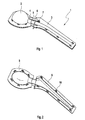
- Fig. 1 shows the perspective view of a mold 1 for producing a hip joint spacer.
- the shape consists of two partial shapes that can be inserted into each other.
- the first part form 2 serves to form the femoral head, while the second part form 3 serves to form the thigh shaft
- the different partial forms for the femoral head For example, they may have different diameters, but different shapes are also conceivable.
- the partial shapes for the thigh shaft can differ, for example, in diameter and length. There are thus a large number of possibilities for how partial shapes for the femoral head are combined with partial forms of the femoral stem. This provides a large number of different spacers for hip endoprostheses.
- the first part form 2 for the femoral head has a receiving portion 4, in which an insertion portion 5 of the second part form 3 can be inserted.
- the receiving portion 4 forms together with a Eischubabites 5 on the part form 3 for the femoral stem of the femoral neck.
- Receiving section 4 and insertion section 5 can be pushed over each other to different heights and fixed in different positions. Thus, the length of the femoral neck can be adjusted as needed.
- tabs 6 are attached to the receiving portion 4 of the partial mold 2 for the femoral head, which protrude beyond the receiving portion 4.
- FIG. 2 is a half-mold for the production of a spacer shown.
- the illustration shows the state after removal of the spacer.
- the elements of the respective molds 2, 3 can likewise be taken apart, so that the mold 1 is opened lengthwise to remove the spacer.
- a half-shell element 8 of the partial shape 2 for the femoral head and a half-shell element 9 of the partial shape 3 for the femoral neck have a plurality of hooks 10. As in FIG. 1 can be seen, these hooks 10 in the closed state engage in openings of the two other half-shell elements, which in Fig. 2 are not shown.
- FIG. 3 shows the connecting elements 6,7, which serve to fasten the first part mold 2 and the second part mold 3 to each other, in detail.
- the tabs 6 have projections 11 which engage in grooves 7 which are attached to the part form 3 for the thigh shaft.
- a plurality of grooves are arranged on the part form 3 for the femoral stem, so that the receiving portion 4 can be pushed differently far over the insertion portion 5 and can be fixed there in different positions.
- the forms according to the invention have the advantage that the connecting elements are formed integrally with the part molds, so that handling is considerably simplified.
- the two partial forms simply have to be pushed together.
- the connecting elements engage simultaneously and automatically, so that the assembly of the form is easy and quick to accomplish.
- the spacer can be removed by pulling apart the elements of the part shapes.
- the shape In the embodiment corresponding to the embodiment for a hip joint spacer, the shape consists of only four larger elements.
Abstract
Description
Die vorliegende Erfindung betrifft eine Form zur Herstellung von Spacem für Endoprothesen, sie betrifft insbesondere eine Form zur Herstellung von Spacem für Hüftendoprothesen.The present invention relates to a mold for the production of spacers for endoprostheses, and more particularly relates to a mold for the production of spacers for hip endoprostheses.
In Deutschland werden zurzeit ca. 200.000 Hüfttotalendoprothesen pro Jahr implantiert. Als relevante Komplikationen können Früh- und Spätinfektionen des Implantatlagers auftreten. Die Infektrate wird dabei auf 2-6% beziffert, je nachdem ob es sich um eine Primärimplantation oder eine Revisionsoperation handelt. Die vermutete Dunkelziffer liegt weitaus höher, insbesondere bzgl. kritischer Keime (z. B. MRSA). Kommt es zur Infektion im Bereich des künstlichen Gelenkes, wird im ersten Schritt versucht, den Infekt mittels konsequenter chirurgischer Sanierung kombiniert mit testgerechten Antibiotika zu behandeln. In sehr vielen Fällen ist dies alleine jedoch nicht wirksam. Die infizierte Prothese muss dann operativ entfernt werden. Dabei wird gleichzeitig der durch die Infektion kompromittierte Knochen mit entfernt. Je weiter fortgeschritten die Infektion, desto größer die Knochendefekte.Approximately 200,000 total hip replacements per year are currently being implanted in Germany. As relevant complications, premature and late infections of the implant site can occur. The infect rate is estimated at 2-6%, depending on whether it is a primary implantation or a revision surgery. The assumed dark figure is much higher, especially with regard to critical germs (eg MRSA). If it comes to the infection in the area of the artificial joint, the first step is to treat the infection by means of consistent surgical rehabilitation combined with test-appropriate antibiotics. In many cases, however, this alone is not effective. The infected prosthesis must then be surgically removed. At the same time, the bone compromised by the infection is also removed. The more advanced the infection, the greater the bone defects.
Nachdem die infizierte Prothese entfernt wurde, platziert man, um die Stabilität des Gelenkes aufrecht zu erhalten, an Stelle der Prothese einen sogenannten Platzhalter oder Spacer. Während der Behandlung der Infektion wird das Gelenk des Patienten bis zum negativen Keimnachweis alle 3-5 Tage revidiert, debridiert und gespült, Abstriche entnommen und der Spacer ggf. ausgetauscht, parallel zur testgerechten antibiotischen Behandlung. Die Dauer der Behandlung hängt von verschiedenen Faktoren ab, wie zum Beispiel dem Ansprechen der Bakterien auf das Antibiotikum, der Verfassung des Patienten, dem Schweregrad der Infektion etc.. Nach belegter Sanierung der Infektion wird dem Patienten eine Revisionsprothese implantiert.After the infected prosthesis has been removed, a so-called spacer or spacer is placed instead of the prosthesis in order to maintain the stability of the joint. During the treatment of the infection, the joint of the patient until the negative detection of germs every 3-5 days revised, debrided and rinsed, taken swabs and the spacer replaced if necessary, in parallel with the test-appropriate antibiotic treatment. The duration of the treatment depends on various factors, such as the response of the bacteria to the antibiotic, the condition of the patient, the severity of the infection, etc. After proper rehabilitation of the infection, the patient is implanted with a revision prosthesis.
Die zurzeit auf dem Markt befindlichen Spacer bestehen aus Kunststoff (PMMA). Im Inneren kann sich eine Verstärkung aus Edelstahl befinden (siehe z. B. bei Hüftgelenk-Spacem). Die Geometrie der Hüftgelenk-Spacer orientiert sich im Groben am Design einer Primärprothese. Unberücksichtigt bleiben dabei die individuellen Zuschnitte am Hüftgelenk, die von der ursprünglich implantierten Prothese vorgegeben sind.The spacers currently on the market are made of plastic (PMMA). Inside there may be a stainless steel reinforcement (see, for example, in the case of hip joint spacers). The geometry of the hip joint spacers roughly follows the design of a primary prosthesis. The individual cuts at the hip joint, which are predetermined by the originally implanted prosthesis, are disregarded.
Alternativ zu den oben genannten Spacern verwenden manche Operateure Platzhalter, die während der Operation eigenhändig aus Knochenzement hergestellt werden. Dem Knochenzement kann während der Herstellung wahlweise antibiotisch wirksame Bestandteile zugemischt werden. Zur Herstellung dieser Spacer werden Formen benötigt.As an alternative to the above spacers, some surgeons use placeholders, which are made by hand from bone cement during surgery. The bone cement may be added during manufacture either antibiotically active ingredients. Molds are needed to make these spacers.
Eine solche Form für Spacer-Implantate wird in
In
Aufgabe der Erfindung ist es daher, eine Form für Spacer bereitzustellen, die einfach und schnell mit Knochenzement gefüllt werden kann, und aus der der fertige Spacer genauso einfach und schnell wieder entnommen werden kann.The object of the invention is therefore to provide a form for spacers that can be easily and quickly filled with bone cement, and from which the finished spacer can be removed just as easily and quickly.
Diese Aufgabe wird durch den Gegenstand der unabhängigen Ansprüche gelöst. Bevorzugte Ausführungsformen sind in den abhängigen Ansprüchen wiedergegeben.This object is solved by the subject matter of the independent claims. Preferred embodiments are given in the dependent claims.
Die Aufgabe wird durch eine Form für einen Endoprothesenspacer gemäß Anspruch gelöst. Weiterbildungen der Erfindung sind durch die Unteransprüche definiert.The object is achieved by a form for a Endoprothesenspacer according to claim. Further developments of the invention are defined by the subclaims.
Die erfindungsgemäße Form für einen Spacer besteht aus mindestens zwei Teilformen, bevorzugt aus zwei Teilformen, welche zusammengesteckt werden können. Das bedeutet, dass die Teilformen an dem Ende, an dem sie zusammengesteckt werden, so ausgebildet sind, dass sie passgenau ineinandergeführt werden können. Bei einer besonders bevorzugten Ausführungsform der Erfindung handelt es sich um einen Hüftgelenkspacer, der am Oberschenkelhals zusammengesetzt wird.The form according to the invention for a spacer consists of at least two partial forms, preferably of two partial forms, which can be put together. This means that the part molds at the end where they are put together, are designed so that they can be inserted into each other accurately. In a particularly preferred embodiment of the invention is a Hüftgelenkspacer, which is assembled at the thigh neck.
Erfindungsgemäß weist eine der Teilformen, bevorzugt die Teilform für den Hüftgelenkkopf einen Aufnahmeabschnitt auf, in den ein Einschubabschnitt der anderen Teilform, bevorzugt der Teilform für den Hüftgelenkschaft, einführbar ist. Zumindest einer von beiden Abschnitten, entweder der Aufnahmeabschnitt oder der Einschubabschnitt, weist Verbindungselemente auf, die integriert mit der Teilform ausgebildet sind und eine form-, kraft- oder form- und kraftschlüssige Verbindung mit der zweiten Teilform bilden können.According to the invention, one of the partial molds, preferably the partial mold for the hip joint head, has a receiving section into which an insertion section of the other partial mold, preferably the partial mold for the hip joint shaft, can be inserted. At least one of the two sections, either the receiving section or the insertion section, has connecting elements which are formed integrally with the partial mold and can form a positive, non-positive or positive and non-positive connection with the second partial mold.
In einer bevorzugten Ausführungsform weist eine Teilform mehrere Verbindungselemente auf, die in Abständen derart ausgebildet sind, dass der Aufnahmeabschnitt, der über den Einschubabschnitt geschoben wird, in unterschiedlichen Positionen fixiert werden und so die Länge des Oberschenkelhalses angepasst werden. Bevorzugt sind 2 bis 10 Verbindungelemente, besonders bevorzugt 2 bis 5 Verbindungselemente. Besonders bevorzugt sind an der Teilform mit dem Einschubabschnitt eine Mehrzahl Verbindungselemente ausgebildet.In a preferred embodiment, a partial mold has a plurality of connecting elements, which are formed at intervals such that the receiving portion, which is pushed over the insertion portion, are fixed in different positions and thus the length of the femoral neck are adjusted. Preference is given to 2 to 10 connecting elements, more preferably 2 to 5 connecting elements. Particularly preferably, a plurality of connecting elements are formed on the partial mold with the insertion section.
Bevorzugt handelt es sich bei den Verbindungselementen um Rastelemente am Aufnahmeabschnitt, die mit komplementären Verbindungselementen der zweiten Teilform in der der Einschubrichtung entgegengesetzten Richtung eine formschlüssige Verbindung bilden.Preferably, the connecting elements are latching elements on the receiving portion, which form a positive connection with complementary connecting elements of the second part form in the direction opposite to the insertion direction.
Besonderes bevorzugt sind die Rastelemente an Laschen ausgebildet, die an dem Aufnahmenabschnitt angebracht sind. Bevorzugt handelt es sich bei den Rastelementen um Vorsprünge, wie zum Beispiel Haken. Bei den Verbindungselementen der zweiten Teilform kann es sich zum Beispiel um Rillen handeln, in die die Haken passen. Durch ihre längliche Ausbildung besitzen die Laschen eine gewisse Elastizität, die es ermöglicht, dass sie über die zweite Teilform geschoben werden können. Diese Elastizität kann jedoch auch durch die Verwendung eines elastischen Materials gewährleistet sein.Particularly preferably, the latching elements are formed on tabs which are attached to the receiving portion. Preferably, the locking elements are projections, such as hooks. The connecting elements of the second part form may, for example, be grooves in which the hooks fit. Due to their elongated design, the tabs have a certain elasticity, which makes it possible that they can be pushed over the second part form. However, this elasticity can also be ensured by the use of an elastic material.
Bevorzugt befinden sich die Rastelemente an Laschen, die über den Aufnahmeabschnitt hinausragen. Die Laschen sollten elastisch sein, so dass das Einführen des Einschubabschnitts erleichtert wird.Preferably, the locking elements are located on tabs which protrude beyond the receiving portion. The tabs should be elastic, so that the insertion of the insertion section is facilitated.
Denkbar ist jedoch auch, dass diese Vorsprünge nicht an Laschen, sondern direkt im Aufnahmeabschnitt der ersten Teilform ausgebildet sind. Die Vorsprünge können auch durch einen umlaufenden vorspringenden Rand gebildet sein, der in eine umlaufende Nut in der anderen Teilform greift.It is also conceivable, however, that these projections are not formed on tabs, but directly in the receiving portion of the first part form. The projections may also be formed by a circumferential projecting edge which engages in a circumferential groove in the other part form.
Damit die Laschen mit den Rastelementen sicher auf die komplementären Verbindungselemente ausgerichtet werden können, können die Querschnitte des rohrförmigen Aufnahmeabschnitts und des rohrförmigen Einschubabschnitts mehreckig, wie zum Beispiel viereckig oder sechseckig, oder auch oval sein. Damit kann die erste Teilform auch nicht nur geringfügig im Hinblick auf die zweite Teilform verdreht werden. Damit der Querschnitt annähernd den anatomischen Vorgaben entspricht, sollten die Kanten abgerundet sein.In order that the tabs with the latching elements can be securely aligned with the complementary connecting elements, the cross sections of the tubular receiving section and the tubular insert section can be polygonal, such as quadrangular or hexagonal, or even oval. Thus, the first part shape can not be twisted only slightly with respect to the second part form. In order for the cross section to approximate the anatomical specifications, the edges should be rounded.
Anstelle der Rastelemente können auch Federelemente an dem Aufnahmeabschnitt oder dem Einschubabschnitt ausgebildet sein, die die zweite Teilform durch Federkraft und damit kraftschlüssig in Position halten. In diesem Fall muss die zweite Teilform keine komplementären Elemente aufweisen. Von Vorteil wäre eine aufgeraute Oberfläche.Instead of the latching elements and spring elements may be formed on the receiving portion or the insertion portion, which hold the second part form by spring force and thus non-positively in position. In this case, the second part form does not have to have complementary elements. An advantage would be a roughened surface.
Bei der Herstellung des Spacers werden zunächst die beiden Formteile gefüllt und anschließend zusammengesteckt und über die Rastelemente fixiert.In the production of the spacer, the two mold parts are first filled and then put together and fixed on the locking elements.
Jede Teilform besteht bevorzugt aus mehreren Elementen, die zusammengesetzt werden können. Insbesondere besteht jede Teilform aus zwei Halbschalelementen, die einen flachen Rand aufweisen. Die Halbschalelemente können mit ihren Rändern aufeinandergelegt werden. Bevorzugt sind an den Rändern lösbare Befestigungsmittel angeordnet, die die Halbschalelemente aneinander befestigen. Bei diesen Befestigungsmitteln handelt es sich bevorzugt um Haken an einem Halbschalelement, die in Öffnungen des zweiten Halbschalelementes greifen. Die Haken sind bevorzugt elastisch und abgerundet, so dass beim Aufwenden einer bestimmten Kraft die Halbschalelemente auseinandergezogen werden können, um den Spacer entnehmen zu können.Each partial form preferably consists of several elements that can be put together. In particular, each partial mold consists of two half-shell elements which have a flat edge. The half-shell elements can be stacked with their edges. Preferably, releasable fastening means are arranged at the edges, which fasten the half-shell elements to one another. These fastening means are preferably hooks on a half-shell element, which engage in openings of the second half-shell element. The hooks are preferably elastic and rounded, so that when applying a certain force, the half-shell elements can be pulled apart to remove the spacer can.
Die Formen können aus jedem beliebigen biokompatiblen Material hergestellt werden. Es gibt verschiedene Polymere, die für diese Anwendungen geeignet sind. Besonders geeignet sind formstabile, harte Materialien. Beispiele hierfür sind Polyethylen, Polypropylen und Polyetherketon. Diese Materialien haben eine ausreichende Festigkeit, so dass sie sich während der Herstellung der Spacer nicht verformen. Prinzipiell sind alle biokompatiblen Materialien geeignet, aus denen sich die Formen herstellen lassen, unter der Voraussetzung, dass sie keine chemische Reaktion mit Knochenzement oder Antibiotikum eingehen. Da die Form aus zwei Teilformen besteht, die separat gefüllt werden, kann sie auch intransparent sein.The molds can be made of any biocompatible material. There are several polymers that are suitable for these applications. Particularly suitable are dimensionally stable, hard materials. Examples include polyethylene, polypropylene and polyether ketone. These materials have sufficient strength so that they do not deform during manufacture of the spacers. In principle, all biocompatible materials are suitable from which the molds can be produced, provided that they do not undergo a chemical reaction with bone cement or antibiotic. Since the mold consists of two sub-forms, which are filled separately, they can also be non-transparent.
Wahlweise kann vor dem Füllen der Form auch ein Verstärkungselement eingesetzt werden. Es handelt sich dabei bevorzugt um ein längliches flaches Element, das in seiner äußeren Form dem Querschnitt der Form folgt, wobei jedoch ausreichend Abstand zur Form bleibt. Das Verstärkungselement ist bevorzugt aus Edelstahl gefertigt. Es weist bevorzugt Löcher auf, so dass der Knochenzement beim Füllen der Form in diese Löcher eindringen kann. Nach dem Aushärten ist das Verstärkungselement fest mit dem Knochenzement verbunden.Optionally, a reinforcing element may also be used prior to filling the mold. It is preferably an elongate flat element which follows in its outer shape the cross section of the mold, but remains sufficiently far away from the mold. The reinforcing element is preferably made of stainless steel. It preferably has holes, so that the bone cement can penetrate into these holes when filling the mold. After curing, the reinforcing element is firmly connected to the bone cement.
Im Weiteren wird die vorliegende Erfindung anhand der beiliegenden Zeichnungen genauer beschrieben. Es zeigen:
-
Fig. 1 eine perspektivische Darstellung eines Ausführungsbeispiels einer erfindungsgemäßen Form für einen Hüftspacer, -
Fig. 2 eine perspektivische Darstellung eines Ausführungsbeispiels einer erfindungsgemäßen halben Form für einen Hüftspacer, und -
Fig. 3 eine seitliche Ansicht eines Ausschnitts aus einer erfindungsgemäßen Form.
-
Fig. 1 a perspective view of an embodiment of a form according to the invention for a Hüftspacer, -
Fig. 2 a perspective view of an embodiment of a half-mold according to the invention for a Hüftspacer, and -
Fig. 3 a side view of a section of a mold according to the invention.
In den Figuren bezeichnen dieselben Bezugszeichen gleiche oder funktionsgleiche Komponenten, soweit nichts Gegenteiliges angegeben ist.In the figures, the same reference numerals designate the same or functionally identical components, unless indicated otherwise.
Um den Spacer genau an die anatomischen Bedingungen des Patienten anpassen zu können, stehen unterschiedliche Teilformen zur Verfügung. Die verschiedenen Teilformen für den Oberschenkelkopf können zum Beispiel unterschiedliche Durchmesser haben, aber es sind auch unterschiedliche Formen denkbar. Die Teilformen für den Oberschenkelschaft können sich z.B. in Durchmesser und Länge unterscheiden. Es besteht somit eine Vielzahl von Möglichkeiten, wie Teilformen für den Oberschenkelkopf mit Teilformen des Oberschenkelschaftes kombiniert werden. Damit steht eine große Anzahl unterschiedlicher Spacer für Hüftendoprothesen zur Verfügung.In order to adapt the spacer exactly to the anatomical conditions of the patient, different partial forms are available. The different partial forms for the femoral head For example, they may have different diameters, but different shapes are also conceivable. The partial shapes for the thigh shaft can differ, for example, in diameter and length. There are thus a large number of possibilities for how partial shapes for the femoral head are combined with partial forms of the femoral stem. This provides a large number of different spacers for hip endoprostheses.
Beide Teilformen werden an einem Abschnitt zusammengefügt, der der Ausbildung des Oberschenkelhalses dient. Die erste Teilform 2 für den Oberschenkelkopf weist einen Aufnahmeabschnitt 4 auf, in den ein Einschubabschnitt 5 der zweiten Teilform 3 eingeführt werden kann. Nach dem Zusammenfügen der Teilformen 2 und 3 bildet der Aufnahmenabschnitt 4 zusammen mit einem Eischubabschnitt 5 an der Teilform 3 für den Oberschenkelschaft den Oberschenkelhals aus. Aufnahmeabschnitt 4 und Einschubabschnitt 5 können unterschiedlich weit übereinander geschoben werden und in verschiedenen Positionen fixiert werden. So kann auch die Länge des Oberschenkelhalses nach Bedarf eingestellt werden.Both partial forms are joined together on a section that serves to form the thigh neck. The
Die beiden Teilformen werden mit Hilfe von Rastelementen 6,7 aneinander fixiert. In der vorliegenden Ausführungsform sind am Aufnahmeabschnitt 4 der Teilform 2 für den Oberschenkelkopf Laschen 6 befestigt, die über den Aufnahmeabschnitt 4 hinausragen.The two partial shapes are fixed together by means of locking
In
Die erfindungsgemäßen Formen haben den Vorteil, dass die Verbindungselemente integriert mit den Teilformen ausgebildet sind, so dass die Handhabung erheblich vereinfacht ist. Die beiden Teilformen müssen lediglich einfach zusammengeschoben werden. Die Verbindungselemente greifen gleichzeitig und automatisch, so dass das Zusammensetzen der Form einfach und schnell zu bewerkstelligen ist. Genauso einfach und schnell kann der Spacer entnommen werden, indem die Elemente der Teilformen auseinandergezogen werden. Bei der der Ausführungsform entsprechenden Form für einen Hüftgelenkspacer besteht die Form lediglich aus vier größeren Elementen.The forms according to the invention have the advantage that the connecting elements are formed integrally with the part molds, so that handling is considerably simplified. The two partial forms simply have to be pushed together. The connecting elements engage simultaneously and automatically, so that the assembly of the form is easy and quick to accomplish. Just as easily and quickly, the spacer can be removed by pulling apart the elements of the part shapes. In the embodiment corresponding to the embodiment for a hip joint spacer, the shape consists of only four larger elements.
- 11
- Form für einen HoftgelenkspacerShape for a Hoftgelenkspacer
- 22
- Teilform für OberschenkelkopfPart form for femoral head
- 33
- Teilform für OberschenkelschaftPartial form for thigh shaft
- 44
- Aufnahmeabschnittreceiving portion
- 55
- Einschubabschnittinsert portion
- 66
- Lascheflap
- 77
- Rastelementelocking elements
- 88th
- Halbschalehalf shell
- 99
- Halbschalehalf shell
- 1010
- Hakenhook
- 1111
- Verbindungselementefasteners
Claims (10)
dadurch gekennzeichnet, dass
die erste Teilform (2) an einer offenen Seite einen Aufnahmeabschnitt (4) aufweist, in den ein Einschubabschnitt (5) an der offenen Seite der zweiten Teilform (3) einschiebbar ist,
wobei die erste Teilform (2) Verbindungselemente (11) an dem Aufnahmeabschnitt (4) oder die zweite Teilform Verbindungselemente am Einschubabschnitt (5) aufweist, die integriert mit der Teilform (2,3) ausgebildet sind, und die andere Teilform derart ausgebildet ist, dass die Verbindungselemente (11) an mehreren Stellen der anderen Teilform (3,2) angreifen können, derart dass der Aufnahmeabschnitt (4), der über den Einschubabschnitt (5) schiebbar ist, über eine form- und/oder kraftschlüssige Verbindung in unterschiedlichen Positionen fixierbar ist.Mold for the production of spacers for endoprostheses containing at least two partial forms,
characterized in that
the first part form (2) has a receiving section (4) on an open side, into which an insertion section (5) can be inserted on the open side of the second part form (3),
wherein the first part mold (2) has connecting elements (11) on the receiving section (4) or the second part mold has connecting elements on the insertion section (5) which are formed integrally with the part mold (2, 3) and the other part mold is formed in such a way in that the connecting elements (11) can engage at several points of the other part form (3, 2) such that the receiving section (4), which can be pushed over the insertion section (5), is in different positions via a positive and / or non-positive connection can be fixed.
dadurch gekennzeichnet, dass
die Verbindungselemente (11) Rastelemente an der ersten Teilform (2) mit dem Aufnahmeabschnitt sind, die in komplementäre Elemente (7) an der zweiten Teilform (3) passenMold according to claim 1,
characterized in that
the connecting elements (11) are latching elements on the first part form (2) with the receiving section, which fit into complementary elements (7) on the second part form (3)
dadurch gekennzeichnet, dass
die zweite Teilform (3) zu jedem Rastelement (11) der ersten Teilform (2) mehrere nebeneinander angeordnete komplementäre Elemente (7) aufweist.Mold according to claim 2,
characterized in that
the second part form (3) for each locking element (11) of the first part form (2) has a plurality of juxtaposed complementary elements (7).
dadurch gekennzeichnet, dass
zu jedem komplementären Element (7) der zweiten Teilform mehrere nebeneinander angeordnete Rastelemente (11) der ersten Teilform (2) vorhanden sind.Mold according to claim 2,
characterized in that
to each complementary element (7) of the second part form a plurality of juxtaposed latching elements (11) of the first part form (2) are present.
dadurch gekennzeichnet, dass
sie zur Herstellung eines Spacers für eine Hüftendoprothese dient, wobei eine der beiden Teilformen (2,3) die Form eines Oberschenkelkopfes mit Oberschenkelhalsansatz umgibt und die andere Teilform (3,2) die Form eines Schaftes mit Oberschenkelhalsansatz umgibt.Mold according to one of the preceding claims,
characterized in that
it is used for producing a spacer for a hip endoprosthesis, wherein one of the two partial shapes (2,3) surrounds the shape of a femoral head with femoral neck approach and the other part form (3,2) surrounds the shape of a shank with femoral neck approach.
dadurch gekennzeichnet, dass
jede Teilform (2,3) aus mindestens zwei Elementen besteht.Mold according to one of the preceding claims,
characterized in that
each sub-form (2,3) consists of at least two elements.
dadurch gekennzeichnet, dass
jede Teilform (2,3) aus zwei Halbschalelementen besteht.Mold according to claim 6,
characterized in that
Each partial form (2,3) consists of two half-shell elements.
dadurch gekennzeichnet, dass
die Elemente einer Teilform (2,3) umlaufende aufeinander passende Verbindungsbereiche (8,9) aufweisen, die durch lösbare Befestigungsmittel (10) miteinander verbunden werden können.Mold according to claim 6 or 7,
characterized in that
the elements of a partial mold (2, 3) have circumferential mating connecting regions (8, 9) which can be connected to one another by releasable fastening means (10).
dadurch gekennzeichnet, dass
es sich bei den Befestigungsmitteln eines Elementes einer Teilform (2,3) um Öffnungen handelt, in die Haken (10) oder Pilzköpfe eines anderen Elementes der Teilform (2,3) greifen.Mold according to claim 8,
characterized in that
it is in the attachment means of an element of a partial mold (2,3) are openings in the hooks (10) or mushroom heads of another element of the part form (2,3) engage.
gekennzeichnet durch
ein Verstärkungselement.Mold according to one of the preceding claims,
marked by
a reinforcing element.
Applications Claiming Priority (1)
| Application Number | Priority Date | Filing Date | Title |
|---|---|---|---|
| DE102011101084A DE102011101084B3 (en) | 2011-05-10 | 2011-05-10 | Mold for the preparation of spacers for endoprostheses |
Publications (2)
| Publication Number | Publication Date |
|---|---|
| EP2522310A1 true EP2522310A1 (en) | 2012-11-14 |
| EP2522310B1 EP2522310B1 (en) | 2016-04-13 |
Family
ID=46125144
Family Applications (1)
| Application Number | Title | Priority Date | Filing Date |
|---|---|---|---|
| EP12003586.0A Active EP2522310B1 (en) | 2011-05-10 | 2012-05-08 | Mould for producing spacers for endoprosthetics |
Country Status (2)
| Country | Link |
|---|---|
| EP (1) | EP2522310B1 (en) |
| DE (1) | DE102011101084B3 (en) |
Cited By (10)
| Publication number | Priority date | Publication date | Assignee | Title |
|---|---|---|---|---|
| WO2013086177A1 (en) * | 2011-12-06 | 2013-06-13 | Holt Christopher J | Spacer mold for orthopedic implants |
| DE102015104704A1 (en) | 2015-03-27 | 2016-09-29 | Heraeus Medical Gmbh | Spacer form and method of making hip spacers |
| CN107595444A (en) * | 2017-11-03 | 2018-01-19 | 青田县人民医院 | A kind of preparation method of near end of thighbone bone cement prosthese mould and the prosthese |
| CN107802380A (en) * | 2017-10-31 | 2018-03-16 | 北京爱康宜诚医疗器材有限公司 | Femoral stem sept mould |
| IT201700048295A1 (en) * | 2017-05-04 | 2018-11-04 | G21 S R L | Mold and method for forming an orthopedic spacer in medical cement. |
| EP3881803A1 (en) | 2020-03-20 | 2021-09-22 | Heraeus Medical GmbH | Device and method for producing spacers |
| EP3900680A1 (en) | 2020-04-24 | 2021-10-27 | Heraeus Medical GmbH | Device and method for producing spacers with variable head |
| EP3906896A1 (en) | 2020-05-07 | 2021-11-10 | Heraeus Medical GmbH | Manufacture of spacers in casting mould with kink or clamp mechanism |
| EP3939546A1 (en) | 2020-07-17 | 2022-01-19 | Heraeus Medical GmbH | Device and method for producing spacers |
| EP3957280A1 (en) | 2020-08-17 | 2022-02-23 | Heraeus Medical GmbH | Device and method for producing spacers |
Families Citing this family (1)
| Publication number | Priority date | Publication date | Assignee | Title |
|---|---|---|---|---|
| AU2021200566B2 (en) * | 2020-03-20 | 2022-06-02 | Heraeus Medical Gmbh | Device and method for producing spacers |
Citations (4)
| Publication number | Priority date | Publication date | Assignee | Title |
|---|---|---|---|---|
| US20070222114A1 (en) | 2006-03-23 | 2007-09-27 | Ziran Bruce H | Method of forming a temporary implant and mold assembly for same |
| WO2009107378A1 (en) | 2008-02-26 | 2009-09-03 | 本田技研工業株式会社 | Controller for internal-combustion engine |
| DE202009012964U1 (en) * | 2009-09-28 | 2010-03-18 | Medizinische Hochschule Hannover - Anstalt des öffentlichen Rechts | Casting mold for a cement large head for total hip arthroplasty |
| US20100102484A1 (en) * | 2008-10-29 | 2010-04-29 | Sean Haney | Spacer molds with releasable securement |
Family Cites Families (4)
| Publication number | Priority date | Publication date | Assignee | Title |
|---|---|---|---|---|
| US6155812A (en) * | 1998-07-15 | 2000-12-05 | Biomet, Inc | Cement mold for a temporary implant |
| DE102007032014B3 (en) * | 2007-07-10 | 2008-10-02 | Aesculap Ag & Co. Kg | Hip-joint implant, has shaft for inserting into long bone, and includes test neck-piece |
| US7637729B2 (en) * | 2007-12-13 | 2009-12-29 | Biomet Manufacturing Corp. | Modular articulating cement spacer mold |
| DE102008030261A1 (en) * | 2008-06-18 | 2009-12-24 | Aesculap Ag | Modular trial implant system |
-
2011
- 2011-05-10 DE DE102011101084A patent/DE102011101084B3/en active Active
-
2012
- 2012-05-08 EP EP12003586.0A patent/EP2522310B1/en active Active
Patent Citations (4)
| Publication number | Priority date | Publication date | Assignee | Title |
|---|---|---|---|---|
| US20070222114A1 (en) | 2006-03-23 | 2007-09-27 | Ziran Bruce H | Method of forming a temporary implant and mold assembly for same |
| WO2009107378A1 (en) | 2008-02-26 | 2009-09-03 | 本田技研工業株式会社 | Controller for internal-combustion engine |
| US20100102484A1 (en) * | 2008-10-29 | 2010-04-29 | Sean Haney | Spacer molds with releasable securement |
| DE202009012964U1 (en) * | 2009-09-28 | 2010-03-18 | Medizinische Hochschule Hannover - Anstalt des öffentlichen Rechts | Casting mold for a cement large head for total hip arthroplasty |
Cited By (20)
| Publication number | Priority date | Publication date | Assignee | Title |
|---|---|---|---|---|
| WO2013086177A1 (en) * | 2011-12-06 | 2013-06-13 | Holt Christopher J | Spacer mold for orthopedic implants |
| US9937047B2 (en) | 2011-12-06 | 2018-04-10 | Zimmer, Inc. | Spacer mold for orthopedic implants |
| US10399248B2 (en) | 2015-03-27 | 2019-09-03 | Heraeus Medical Gmbh | Spacer mould and method for producing hip spacers |
| DE102015104704A1 (en) | 2015-03-27 | 2016-09-29 | Heraeus Medical Gmbh | Spacer form and method of making hip spacers |
| EP3075357A1 (en) | 2015-03-27 | 2016-10-05 | Heraeus Medical GmbH | Spacer mould and method for producing hip spacers |
| DE102015104704B4 (en) * | 2015-03-27 | 2016-10-06 | Heraeus Medical Gmbh | Spacer form and method of making hip spacers |
| CN105997308A (en) * | 2015-03-27 | 2016-10-12 | 贺利氏医疗有限责任公司 | Spacer mould and method for producing hip spacers |
| CN105997308B (en) * | 2015-03-27 | 2018-01-23 | 贺利氏医疗有限责任公司 | For producing the sept mould and method of hip sept |
| IT201700048295A1 (en) * | 2017-05-04 | 2018-11-04 | G21 S R L | Mold and method for forming an orthopedic spacer in medical cement. |
| WO2018203150A1 (en) * | 2017-05-04 | 2018-11-08 | G21 S.R.L. | A mould and a method for forming an orthopaedic spacer made of medical cement |
| CN107802380A (en) * | 2017-10-31 | 2018-03-16 | 北京爱康宜诚医疗器材有限公司 | Femoral stem sept mould |
| CN107595444A (en) * | 2017-11-03 | 2018-01-19 | 青田县人民医院 | A kind of preparation method of near end of thighbone bone cement prosthese mould and the prosthese |
| CN107595444B (en) * | 2017-11-03 | 2023-11-21 | 青田县人民医院 | Proximal femur bone cement prosthesis die and manufacturing method of prosthesis |
| EP3881803A1 (en) | 2020-03-20 | 2021-09-22 | Heraeus Medical GmbH | Device and method for producing spacers |
| EP3900680A1 (en) | 2020-04-24 | 2021-10-27 | Heraeus Medical GmbH | Device and method for producing spacers with variable head |
| EP3906896A1 (en) | 2020-05-07 | 2021-11-10 | Heraeus Medical GmbH | Manufacture of spacers in casting mould with kink or clamp mechanism |
| EP3939546A1 (en) | 2020-07-17 | 2022-01-19 | Heraeus Medical GmbH | Device and method for producing spacers |
| EP3957280A1 (en) | 2020-08-17 | 2022-02-23 | Heraeus Medical GmbH | Device and method for producing spacers |
| JP2022033705A (en) * | 2020-08-17 | 2022-03-02 | ヘレウス メディカル ゲーエムベーハー | Device and method for producing spacers |
| US11865006B2 (en) | 2020-08-17 | 2024-01-09 | Heraeus Medical Gmbh | Device and method for producing spacers |
Also Published As
| Publication number | Publication date |
|---|---|
| DE102011101084B3 (en) | 2012-11-15 |
| EP2522310B1 (en) | 2016-04-13 |
Similar Documents
| Publication | Publication Date | Title |
|---|---|---|
| EP2522310B1 (en) | Mould for producing spacers for endoprosthetics | |
| EP3075357B1 (en) | Spacer mould and method for producing hip spacers | |
| EP2532323B1 (en) | Mould for producing a tibia component of a knee joint spacer | |
| EP2853242B1 (en) | Modular articulated spacer system | |
| EP2826445B1 (en) | Knee spacer system with adjustable spacer | |
| EP2526900B1 (en) | Mould for producing a femur component of a knee joint spacer | |
| EP2030596B1 (en) | Implant for treating bones. | |
| EP3600167B1 (en) | Liner for a prosthesis | |
| EP2803336B1 (en) | Device for the in-situ production of articulating spacers | |
| EP2944290B1 (en) | Prosthetic sheath | |
| DE102014107497A1 (en) | Fixation device for bone fractures | |
| EP3035892B1 (en) | Modular prostheses | |
| EP2680769B1 (en) | Clamping element for setting a bone fracture, modular setting device comprising same and method for producing same | |
| EP3957280B1 (en) | Device and method for producing spacers | |
| DE202014004751U1 (en) | implant | |
| EP3939546B1 (en) | Device and method for producing spacers | |
| WO2014096077A1 (en) | Locakble intramedullary nail comprising at least one insert for receiving a locking screw | |
| EP3651686B1 (en) | Bone implant for use as a gap filler in the correction of a malposition of bone in the domain of dysgnathia and production method | |
| WO2000059409A1 (en) | Bone implant device for generating tissue using bone replacement materials and method for producing said bone implant device | |
| DE102009055826A1 (en) | Device for plate osteosynthesis, has plate system with multiple application specific, stacked, lockable, uniform or curved individual plates of different forms and sizes | |
| DE102013210638A1 (en) | Finger joint prosthesis with self-adjusting anchoring bars | |
| DE202011109808U1 (en) | Clamping element for fixing a bone fracture and selbiges having modular fixation device | |
| EP4342430A1 (en) | Casting mould for finger joint spacer | |
| DE102007018898A1 (en) | Base unit for jaw implant, has middle region oriented along longitudinal direction of bottom part, where ribs extend center-symmetrically on both sides and inside longitudinal halves of bottom part | |
| DE102014019730A1 (en) | Fixation device for bone fractures |
Legal Events
| Date | Code | Title | Description |
|---|---|---|---|
| PUAI | Public reference made under article 153(3) epc to a published international application that has entered the european phase |
Free format text: ORIGINAL CODE: 0009012 |
|
| 17P | Request for examination filed |
Effective date: 20120515 |
|
| AK | Designated contracting states |
Kind code of ref document: A1 Designated state(s): AL AT BE BG CH CY CZ DE DK EE ES FI FR GB GR HR HU IE IS IT LI LT LU LV MC MK MT NL NO PL PT RO RS SE SI SK SM TR |
|
| AX | Request for extension of the european patent |
Extension state: BA ME |
|
| GRAP | Despatch of communication of intention to grant a patent |
Free format text: ORIGINAL CODE: EPIDOSNIGR1 |
|
| RIC1 | Information provided on ipc code assigned before grant |
Ipc: A61F 2/30 20060101AFI20151102BHEP Ipc: A61F 2/36 20060101ALI20151102BHEP |
|
| INTG | Intention to grant announced |
Effective date: 20151123 |
|
| GRAS | Grant fee paid |
Free format text: ORIGINAL CODE: EPIDOSNIGR3 |
|
| GRAA | (expected) grant |
Free format text: ORIGINAL CODE: 0009210 |
|
| AK | Designated contracting states |
Kind code of ref document: B1 Designated state(s): AL AT BE BG CH CY CZ DE DK EE ES FI FR GB GR HR HU IE IS IT LI LT LU LV MC MK MT NL NO PL PT RO RS SE SI SK SM TR |
|
| REG | Reference to a national code |
Ref country code: GB Ref legal event code: FG4D Free format text: NOT ENGLISH |
|
| REG | Reference to a national code |
Ref country code: AT Ref legal event code: REF Ref document number: 789254 Country of ref document: AT Kind code of ref document: T Effective date: 20160415 Ref country code: CH Ref legal event code: EP |
|
| REG | Reference to a national code |
Ref country code: IE Ref legal event code: FG4D Free format text: LANGUAGE OF EP DOCUMENT: GERMAN |
|
| REG | Reference to a national code |
Ref country code: DE Ref legal event code: R096 Ref document number: 502012006675 Country of ref document: DE |
|
| REG | Reference to a national code |
Ref country code: SE Ref legal event code: TRGR |
|
| REG | Reference to a national code |
Ref country code: NL Ref legal event code: FP |
|
| REG | Reference to a national code |
Ref country code: LT Ref legal event code: MG4D |
|
| PG25 | Lapsed in a contracting state [announced via postgrant information from national office to epo] |
Ref country code: BE Free format text: LAPSE BECAUSE OF NON-PAYMENT OF DUE FEES Effective date: 20160531 |
|
| PG25 | Lapsed in a contracting state [announced via postgrant information from national office to epo] |
Ref country code: PL Free format text: LAPSE BECAUSE OF FAILURE TO SUBMIT A TRANSLATION OF THE DESCRIPTION OR TO PAY THE FEE WITHIN THE PRESCRIBED TIME-LIMIT Effective date: 20160413 Ref country code: NO Free format text: LAPSE BECAUSE OF FAILURE TO SUBMIT A TRANSLATION OF THE DESCRIPTION OR TO PAY THE FEE WITHIN THE PRESCRIBED TIME-LIMIT Effective date: 20160713 Ref country code: LT Free format text: LAPSE BECAUSE OF FAILURE TO SUBMIT A TRANSLATION OF THE DESCRIPTION OR TO PAY THE FEE WITHIN THE PRESCRIBED TIME-LIMIT Effective date: 20160413 Ref country code: FI Free format text: LAPSE BECAUSE OF FAILURE TO SUBMIT A TRANSLATION OF THE DESCRIPTION OR TO PAY THE FEE WITHIN THE PRESCRIBED TIME-LIMIT Effective date: 20160413 |
|
| PG25 | Lapsed in a contracting state [announced via postgrant information from national office to epo] |
Ref country code: GR Free format text: LAPSE BECAUSE OF FAILURE TO SUBMIT A TRANSLATION OF THE DESCRIPTION OR TO PAY THE FEE WITHIN THE PRESCRIBED TIME-LIMIT Effective date: 20160714 Ref country code: RS Free format text: LAPSE BECAUSE OF FAILURE TO SUBMIT A TRANSLATION OF THE DESCRIPTION OR TO PAY THE FEE WITHIN THE PRESCRIBED TIME-LIMIT Effective date: 20160413 Ref country code: PT Free format text: LAPSE BECAUSE OF FAILURE TO SUBMIT A TRANSLATION OF THE DESCRIPTION OR TO PAY THE FEE WITHIN THE PRESCRIBED TIME-LIMIT Effective date: 20160816 Ref country code: ES Free format text: LAPSE BECAUSE OF FAILURE TO SUBMIT A TRANSLATION OF THE DESCRIPTION OR TO PAY THE FEE WITHIN THE PRESCRIBED TIME-LIMIT Effective date: 20160413 Ref country code: HR Free format text: LAPSE BECAUSE OF FAILURE TO SUBMIT A TRANSLATION OF THE DESCRIPTION OR TO PAY THE FEE WITHIN THE PRESCRIBED TIME-LIMIT Effective date: 20160413 Ref country code: LV Free format text: LAPSE BECAUSE OF FAILURE TO SUBMIT A TRANSLATION OF THE DESCRIPTION OR TO PAY THE FEE WITHIN THE PRESCRIBED TIME-LIMIT Effective date: 20160413 |
|
| PG25 | Lapsed in a contracting state [announced via postgrant information from national office to epo] |
Ref country code: IT Free format text: LAPSE BECAUSE OF FAILURE TO SUBMIT A TRANSLATION OF THE DESCRIPTION OR TO PAY THE FEE WITHIN THE PRESCRIBED TIME-LIMIT Effective date: 20160413 |
|
| REG | Reference to a national code |
Ref country code: DE Ref legal event code: R097 Ref document number: 502012006675 Country of ref document: DE |
|
| PG25 | Lapsed in a contracting state [announced via postgrant information from national office to epo] |
Ref country code: SK Free format text: LAPSE BECAUSE OF FAILURE TO SUBMIT A TRANSLATION OF THE DESCRIPTION OR TO PAY THE FEE WITHIN THE PRESCRIBED TIME-LIMIT Effective date: 20160413 Ref country code: CZ Free format text: LAPSE BECAUSE OF FAILURE TO SUBMIT A TRANSLATION OF THE DESCRIPTION OR TO PAY THE FEE WITHIN THE PRESCRIBED TIME-LIMIT Effective date: 20160413 Ref country code: DK Free format text: LAPSE BECAUSE OF FAILURE TO SUBMIT A TRANSLATION OF THE DESCRIPTION OR TO PAY THE FEE WITHIN THE PRESCRIBED TIME-LIMIT Effective date: 20160413 Ref country code: EE Free format text: LAPSE BECAUSE OF FAILURE TO SUBMIT A TRANSLATION OF THE DESCRIPTION OR TO PAY THE FEE WITHIN THE PRESCRIBED TIME-LIMIT Effective date: 20160413 Ref country code: RO Free format text: LAPSE BECAUSE OF FAILURE TO SUBMIT A TRANSLATION OF THE DESCRIPTION OR TO PAY THE FEE WITHIN THE PRESCRIBED TIME-LIMIT Effective date: 20160413 Ref country code: MC Free format text: LAPSE BECAUSE OF FAILURE TO SUBMIT A TRANSLATION OF THE DESCRIPTION OR TO PAY THE FEE WITHIN THE PRESCRIBED TIME-LIMIT Effective date: 20160413 |
|
| PLBE | No opposition filed within time limit |
Free format text: ORIGINAL CODE: 0009261 |
|
| STAA | Information on the status of an ep patent application or granted ep patent |
Free format text: STATUS: NO OPPOSITION FILED WITHIN TIME LIMIT |
|
| REG | Reference to a national code |
Ref country code: IE Ref legal event code: MM4A |
|
| PG25 | Lapsed in a contracting state [announced via postgrant information from national office to epo] |
Ref country code: SM Free format text: LAPSE BECAUSE OF FAILURE TO SUBMIT A TRANSLATION OF THE DESCRIPTION OR TO PAY THE FEE WITHIN THE PRESCRIBED TIME-LIMIT Effective date: 20160413 |
|
| REG | Reference to a national code |
Ref country code: FR Ref legal event code: ST Effective date: 20170131 |
|
| 26N | No opposition filed |
Effective date: 20170116 |
|
| PG25 | Lapsed in a contracting state [announced via postgrant information from national office to epo] |
Ref country code: FR Free format text: LAPSE BECAUSE OF NON-PAYMENT OF DUE FEES Effective date: 20160613 |
|
| PG25 | Lapsed in a contracting state [announced via postgrant information from national office to epo] |
Ref country code: IE Free format text: LAPSE BECAUSE OF NON-PAYMENT OF DUE FEES Effective date: 20160508 Ref country code: SI Free format text: LAPSE BECAUSE OF FAILURE TO SUBMIT A TRANSLATION OF THE DESCRIPTION OR TO PAY THE FEE WITHIN THE PRESCRIBED TIME-LIMIT Effective date: 20160413 |
|
| PG25 | Lapsed in a contracting state [announced via postgrant information from national office to epo] |
Ref country code: CY Free format text: LAPSE BECAUSE OF FAILURE TO SUBMIT A TRANSLATION OF THE DESCRIPTION OR TO PAY THE FEE WITHIN THE PRESCRIBED TIME-LIMIT Effective date: 20160413 Ref country code: HU Free format text: LAPSE BECAUSE OF FAILURE TO SUBMIT A TRANSLATION OF THE DESCRIPTION OR TO PAY THE FEE WITHIN THE PRESCRIBED TIME-LIMIT; INVALID AB INITIO Effective date: 20120508 |
|
| PG25 | Lapsed in a contracting state [announced via postgrant information from national office to epo] |
Ref country code: MT Free format text: LAPSE BECAUSE OF FAILURE TO SUBMIT A TRANSLATION OF THE DESCRIPTION OR TO PAY THE FEE WITHIN THE PRESCRIBED TIME-LIMIT Effective date: 20160413 Ref country code: LU Free format text: LAPSE BECAUSE OF NON-PAYMENT OF DUE FEES Effective date: 20160508 Ref country code: IS Free format text: LAPSE BECAUSE OF FAILURE TO SUBMIT A TRANSLATION OF THE DESCRIPTION OR TO PAY THE FEE WITHIN THE PRESCRIBED TIME-LIMIT Effective date: 20160413 Ref country code: MK Free format text: LAPSE BECAUSE OF FAILURE TO SUBMIT A TRANSLATION OF THE DESCRIPTION OR TO PAY THE FEE WITHIN THE PRESCRIBED TIME-LIMIT Effective date: 20160413 Ref country code: TR Free format text: LAPSE BECAUSE OF FAILURE TO SUBMIT A TRANSLATION OF THE DESCRIPTION OR TO PAY THE FEE WITHIN THE PRESCRIBED TIME-LIMIT Effective date: 20160413 |
|
| REG | Reference to a national code |
Ref country code: AT Ref legal event code: MM01 Ref document number: 789254 Country of ref document: AT Kind code of ref document: T Effective date: 20170508 |
|
| PG25 | Lapsed in a contracting state [announced via postgrant information from national office to epo] |
Ref country code: BG Free format text: LAPSE BECAUSE OF FAILURE TO SUBMIT A TRANSLATION OF THE DESCRIPTION OR TO PAY THE FEE WITHIN THE PRESCRIBED TIME-LIMIT Effective date: 20160413 |
|
| PG25 | Lapsed in a contracting state [announced via postgrant information from national office to epo] |
Ref country code: AT Free format text: LAPSE BECAUSE OF NON-PAYMENT OF DUE FEES Effective date: 20170508 |
|
| PG25 | Lapsed in a contracting state [announced via postgrant information from national office to epo] |
Ref country code: AL Free format text: LAPSE BECAUSE OF FAILURE TO SUBMIT A TRANSLATION OF THE DESCRIPTION OR TO PAY THE FEE WITHIN THE PRESCRIBED TIME-LIMIT Effective date: 20160413 |
|
| REG | Reference to a national code |
Ref country code: DE Ref legal event code: R082 Ref document number: 502012006675 Country of ref document: DE Representative=s name: BRAND, NORMEN, DR. RER. NAT., DE Ref country code: DE Ref legal event code: R082 Ref document number: 502012006675 Country of ref document: DE Representative=s name: BRAND, NORMEN, DIPL.-CHEM. UNIV. DR. RER. NAT., DE |
|
| P01 | Opt-out of the competence of the unified patent court (upc) registered |
Effective date: 20230527 |
|
| PGFP | Annual fee paid to national office [announced via postgrant information from national office to epo] |
Ref country code: NL Payment date: 20230519 Year of fee payment: 12 Ref country code: DE Payment date: 20230519 Year of fee payment: 12 Ref country code: CH Payment date: 20230602 Year of fee payment: 12 |
|
| PGFP | Annual fee paid to national office [announced via postgrant information from national office to epo] |
Ref country code: SE Payment date: 20230519 Year of fee payment: 12 |
|
| PGFP | Annual fee paid to national office [announced via postgrant information from national office to epo] |
Ref country code: GB Payment date: 20230524 Year of fee payment: 12 |