EP2525443A1 - Vehicle-side connector and mounting method therefor - Google Patents
Vehicle-side connector and mounting method therefor Download PDFInfo
- Publication number
- EP2525443A1 EP2525443A1 EP12002471A EP12002471A EP2525443A1 EP 2525443 A1 EP2525443 A1 EP 2525443A1 EP 12002471 A EP12002471 A EP 12002471A EP 12002471 A EP12002471 A EP 12002471A EP 2525443 A1 EP2525443 A1 EP 2525443A1
- Authority
- EP
- European Patent Office
- Prior art keywords
- vehicle
- tube portion
- mounting plate
- side connector
- plug
- Prior art date
- Legal status (The legal status is an assumption and is not a legal conclusion. Google has not performed a legal analysis and makes no representation as to the accuracy of the status listed.)
- Granted
Links
Images


Classifications
-
- H—ELECTRICITY
- H01—ELECTRIC ELEMENTS
- H01R—ELECTRICALLY-CONDUCTIVE CONNECTIONS; STRUCTURAL ASSOCIATIONS OF A PLURALITY OF MUTUALLY-INSULATED ELECTRICAL CONNECTING ELEMENTS; COUPLING DEVICES; CURRENT COLLECTORS
- H01R13/00—Details of coupling devices of the kinds covered by groups H01R12/70 or H01R24/00 - H01R33/00
- H01R13/46—Bases; Cases
- H01R13/52—Dustproof, splashproof, drip-proof, waterproof, or flameproof cases
- H01R13/5227—Dustproof, splashproof, drip-proof, waterproof, or flameproof cases with evacuation of penetrating liquids
-
- B—PERFORMING OPERATIONS; TRANSPORTING
- B60—VEHICLES IN GENERAL
- B60L—PROPULSION OF ELECTRICALLY-PROPELLED VEHICLES; SUPPLYING ELECTRIC POWER FOR AUXILIARY EQUIPMENT OF ELECTRICALLY-PROPELLED VEHICLES; ELECTRODYNAMIC BRAKE SYSTEMS FOR VEHICLES IN GENERAL; MAGNETIC SUSPENSION OR LEVITATION FOR VEHICLES; MONITORING OPERATING VARIABLES OF ELECTRICALLY-PROPELLED VEHICLES; ELECTRIC SAFETY DEVICES FOR ELECTRICALLY-PROPELLED VEHICLES
- B60L53/00—Methods of charging batteries, specially adapted for electric vehicles; Charging stations or on-board charging equipment therefor; Exchange of energy storage elements in electric vehicles
- B60L53/10—Methods of charging batteries, specially adapted for electric vehicles; Charging stations or on-board charging equipment therefor; Exchange of energy storage elements in electric vehicles characterised by the energy transfer between the charging station and the vehicle
- B60L53/14—Conductive energy transfer
- B60L53/16—Connectors, e.g. plugs or sockets, specially adapted for charging electric vehicles
-
- H—ELECTRICITY
- H01—ELECTRIC ELEMENTS
- H01R—ELECTRICALLY-CONDUCTIVE CONNECTIONS; STRUCTURAL ASSOCIATIONS OF A PLURALITY OF MUTUALLY-INSULATED ELECTRICAL CONNECTING ELEMENTS; COUPLING DEVICES; CURRENT COLLECTORS
- H01R13/00—Details of coupling devices of the kinds covered by groups H01R12/70 or H01R24/00 - H01R33/00
- H01R13/46—Bases; Cases
- H01R13/52—Dustproof, splashproof, drip-proof, waterproof, or flameproof cases
- H01R13/5205—Sealing means between cable and housing, e.g. grommet
- H01R13/5208—Sealing means between cable and housing, e.g. grommet having at least two cable receiving openings
-
- H—ELECTRICITY
- H01—ELECTRIC ELEMENTS
- H01R—ELECTRICALLY-CONDUCTIVE CONNECTIONS; STRUCTURAL ASSOCIATIONS OF A PLURALITY OF MUTUALLY-INSULATED ELECTRICAL CONNECTING ELEMENTS; COUPLING DEVICES; CURRENT COLLECTORS
- H01R13/00—Details of coupling devices of the kinds covered by groups H01R12/70 or H01R24/00 - H01R33/00
- H01R13/73—Means for mounting coupling parts to apparatus or structures, e.g. to a wall
- H01R13/74—Means for mounting coupling parts in openings of a panel
-
- H—ELECTRICITY
- H01—ELECTRIC ELEMENTS
- H01R—ELECTRICALLY-CONDUCTIVE CONNECTIONS; STRUCTURAL ASSOCIATIONS OF A PLURALITY OF MUTUALLY-INSULATED ELECTRICAL CONNECTING ELEMENTS; COUPLING DEVICES; CURRENT COLLECTORS
- H01R43/00—Apparatus or processes specially adapted for manufacturing, assembling, maintaining, or repairing of line connectors or current collectors or for joining electric conductors
- H01R43/005—Apparatus or processes specially adapted for manufacturing, assembling, maintaining, or repairing of line connectors or current collectors or for joining electric conductors for making dustproof, splashproof, drip-proof, waterproof, or flameproof connection, coupling, or casing
-
- H—ELECTRICITY
- H01—ELECTRIC ELEMENTS
- H01R—ELECTRICALLY-CONDUCTIVE CONNECTIONS; STRUCTURAL ASSOCIATIONS OF A PLURALITY OF MUTUALLY-INSULATED ELECTRICAL CONNECTING ELEMENTS; COUPLING DEVICES; CURRENT COLLECTORS
- H01R2201/00—Connectors or connections adapted for particular applications
- H01R2201/26—Connectors or connections adapted for particular applications for vehicles
-
- Y—GENERAL TAGGING OF NEW TECHNOLOGICAL DEVELOPMENTS; GENERAL TAGGING OF CROSS-SECTIONAL TECHNOLOGIES SPANNING OVER SEVERAL SECTIONS OF THE IPC; TECHNICAL SUBJECTS COVERED BY FORMER USPC CROSS-REFERENCE ART COLLECTIONS [XRACs] AND DIGESTS
- Y02—TECHNOLOGIES OR APPLICATIONS FOR MITIGATION OR ADAPTATION AGAINST CLIMATE CHANGE
- Y02T—CLIMATE CHANGE MITIGATION TECHNOLOGIES RELATED TO TRANSPORTATION
- Y02T10/00—Road transport of goods or passengers
- Y02T10/60—Other road transportation technologies with climate change mitigation effect
- Y02T10/70—Energy storage systems for electromobility, e.g. batteries
-
- Y—GENERAL TAGGING OF NEW TECHNOLOGICAL DEVELOPMENTS; GENERAL TAGGING OF CROSS-SECTIONAL TECHNOLOGIES SPANNING OVER SEVERAL SECTIONS OF THE IPC; TECHNICAL SUBJECTS COVERED BY FORMER USPC CROSS-REFERENCE ART COLLECTIONS [XRACs] AND DIGESTS
- Y02—TECHNOLOGIES OR APPLICATIONS FOR MITIGATION OR ADAPTATION AGAINST CLIMATE CHANGE
- Y02T—CLIMATE CHANGE MITIGATION TECHNOLOGIES RELATED TO TRANSPORTATION
- Y02T10/00—Road transport of goods or passengers
- Y02T10/60—Other road transportation technologies with climate change mitigation effect
- Y02T10/7072—Electromobility specific charging systems or methods for batteries, ultracapacitors, supercapacitors or double-layer capacitors
-
- Y—GENERAL TAGGING OF NEW TECHNOLOGICAL DEVELOPMENTS; GENERAL TAGGING OF CROSS-SECTIONAL TECHNOLOGIES SPANNING OVER SEVERAL SECTIONS OF THE IPC; TECHNICAL SUBJECTS COVERED BY FORMER USPC CROSS-REFERENCE ART COLLECTIONS [XRACs] AND DIGESTS
- Y02—TECHNOLOGIES OR APPLICATIONS FOR MITIGATION OR ADAPTATION AGAINST CLIMATE CHANGE
- Y02T—CLIMATE CHANGE MITIGATION TECHNOLOGIES RELATED TO TRANSPORTATION
- Y02T90/00—Enabling technologies or technologies with a potential or indirect contribution to GHG emissions mitigation
- Y02T90/10—Technologies relating to charging of electric vehicles
- Y02T90/14—Plug-in electric vehicles
Definitions
- the present invention relates to a vehicle-side connector to be connected to a charging connector at the time of charging and to a mounting method therefor.
- a vehicle-side connector of this type is, for example, known from Japanese Unexamined Patent Publication No. H07-29631 .
- a housing chamber facing the outside of a vehicle is provided on a body of the vehicle, and a vehicle-side connector is housed in this housing chamber.
- a tapered water guide portion inclined downward toward the outside of the vehicle is provided on the lower surface of the housing chamber and a drain port is provided at a lower end part of this water guide portion.
- the drain port is open downward and a drain hose is connected to this drain port. Water having entered the housing chamber is brought to the drain hose via the water guide portion and the drain port and is drained to a side below the housing chamber from this drain hose.
- the above drain port is arranged in the housing chamber and the drain hose connected to this drain port is arranged closer to the inside of the vehicle than the body, a battery may be wetted by water drained from the drain hose in the case of a vehicle type in which the battery is disposed below the housing chamber. Further, a pressure difference is created between the inside of the vehicle and the housing chamber, and the water in the drain hose may flow back to the housing chamber due to this pressure difference.
- the present invention was completed in view of the above situation and an object thereof is to improve drainage properties of a connector.
- drainage properties are improved by preventing the reverse flow of drained fluid, liquid or water by draining fluid, liquid or water having entered a vehicle-side connector to the outside of a vehicle.
- a vehicle-side connector to be connected to a charging connector at the time of charging, comprising: a mounting plate which is to be fixed to a body part of a vehicle; a first tube portion which is so provided at the mounting plate as to at least partly penetrate through the mounting plate; a second tube portion projecting from the mounting plate toward the inside of the vehicle and have an open projecting end; a resilient plug which forms a sealed space in the second tube portion by sealing between a wire pulled into the inside of the vehicle from the interior of the first tube portion and an opening of the second tube portion; a plug holder which is mounted to the second tube portion to retain the resilient plug; at least one fluid guide portion which is provided in the sealed space and inclined downwardly toward the outside of the vehicle; and at least one drain port which penetrates though the mounting plate and drains fluid from the fluid guide portion to the outside of the vehicle.
- the sealed space in the second tube portion it is possible to form the sealed space in the second tube portion, bring liquid or fluid in this sealed space to the drain port by the liquid guide portion and drain the liquid to the outside of the vehicle from the drain port by mounting the resilient to the second tube portion. Further, since the sealed space communicates with the atmosphere through the drain port, the reverse flow of liquid or water from the drain port into the sealed space can be prevented regardless of a pressure variation inside the vehicle.
- the plug holder is mounted in the opening of the second tube portion to retain the resilient plug.
- a vehicle-side connector to be connected to a charging connector at the time of charging, comprising a mounting plate which is to be fixed to a body of a vehicle; an inner tube portion which is so provided at the mounting plate as to penetrate through the mounting plate; an outer tube portion which surrounds an outer peripheral side of the inner tube portion over the entire circumference in such a manner as to project from the mounting plate toward the inside of the vehicle and have an open projecting end; a rubber plug which forms a sealed space in the outer tube portion by sealing between a wire pulled into the inside of the vehicle from the interior of the inner tube portion and an opening of the outer tube portion; a rubber plug presser which is mounted in the opening of the outer tube portion to retain the rubber plug; a water guide portion which is provided in the sealed space and inclined downwardly toward the outside of the vehicle; and a drain port which penetrates though the mounting plate and drains water from the water guide portion to the outside of the vehicle.
- the sealed space in the outer tube portion brings water in this sealed space to the drain port by the water guide portion and drain the water to the outside of the vehicle from the drain port by mounting the rubber plug in the opening of the outer tube portion. Further, since the sealed space communicates with the atmosphere through the drain port, the reverse flow of water from the drain port into the sealed space can be prevented regardless of a pressure variation inside the vehicle.
- the vehicle-side connector may further comprise at least one terminal fitting which is or is to be connected to an end of the wire and at least partly accommodated in the first tube portion (particularly the inner tube portion), and a retainer which is mounted to the first tube portion, particularly at least partly in an opening of the first (inner) tube portion, to retain the terminal fitting(s).
- the resilient plug (particularly the rubber plug) may include a base plate portion formed with at least one seal hole through which the wire is inserted in a sealed state.
- the resilient plug (rubber plug) can be more easily fixed particularly by at least partly arranging the base plate portion of the resilient plug (rubber plug) between the retainer and the plug holder (particularly the rubber plug presser).
- the resilient plug may include a peripheral wall portion particularly being tapered and standing from the peripheral edge of the base plate portion.
- the fluid (water) guide portion may be provided from the peripheral wall portion to the second (particularly outer) tube portion.
- fluid (water) guide portion is provided only in the second (outer) tube portion without providing the resilient (rubber) plug with the peripheral wall portion, a long fluid (water) guide portion needs to be formed from the opening of the outer tube portion to the mounting plate and the position of the drain port is located more downward (more away from the first or inner tube portion), wherefore the mounting plate tends to become longer in a downward direction.
- the resilient (rubber) plug is provided with the (particularly tapered) peripheral wall portion and the fluid (water) guide portion is formed from this peripheral wall portion to the second (outer) tube portion according to the above configuration, the fluid (water) guide portion in the second (outer) tube portion can be made shorter, with the result that the position of the drain port can be located more upward (closer to the inner tube portion) and the mounting plate can be made shorter in a vertical direction.
- Forward and backward movements of the resilient plug may be prevented by mounting the base plate portion between the retainer and the plug holder in forward and backward directions substantially without forming any clearance.
- the fluid guide portion may comprise a portion having a tapered shape as to be enlarged downwardly toward the mounting plate.
- Fluid having entered a portion of the first tube portion and reached the sealed space may be guided obliquely downwardly via one or more drain plates and brought to a drain channel along an inclined surface of the resilient plug and then drained to the outside of the vehicle through the drain port.
- a mounting or assembling method for a vehicle-side connector in particular according to the above aspect of the invention or a particular embodiment thereof, to be connected to a charging connector at the time of charging, comprising the following steps: fixing a mounting plate to a body part of a vehicle; providing an first tube portion at the mounting plate as to at least partly penetrate through the mounting plate; providing a second tube portion projecting from the mounting plate toward the inside of the vehicle and have an open projecting end; mounting a resilient plug such as to form a sealed space in the second tube portion by sealing between a wire pulled into the inside of the vehicle from the interior of the first tube portion and an opening of the second tube portion; mounting a plug holder to the second tube portion to retain the resilient plug; providing at least one fluid guide portion in the sealed space and inclined downwardly toward the outside of the vehicle; and providing at least one drain port which penetrates though the mounting plate and drains fluid from the fluid guide portion to the outside of the vehicle.
- the second tube portion may be provided so as to at least partly surround an outer peripheral side of the first tube portion over the entire circumference.
- the plug holder may be mounted in the opening of the second tube portion to retain the resilient plug.
- the method particularly may further comprise the following steps: connecting at least one terminal fitting to an end of the wire and at least partly accommodated in the first tube portion; and mounting a retainer in an opening of the first tube portion to retain the terminal fitting.
- the resilient plug may include a base plate portion formed with at least one seal hole through which the wire is inserted in a sealed state, wherein forward and backward movements of the resilient plug preferably are prevented by mounting the base plate portion between the retainer and the plug holder in forward and backward directions substantially without forming any clearance.
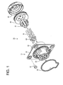
- a vehicle-side connector 10 in this embodiment is to be connected to a battery (not shown) installed in an electric vehicle, a hybrid vehicle or the like, and is connected to a charging connector (not shown) at the time of charging into this battery.
- the vehicle-side connector 10 includes a housing 11 to be fastened to a body part (such as an outer panel P forming a body) of the vehicle particularly by one or more bolts B1.
- a mounting hole B2 is formed in the body part (particularly outer panel) P and the housing 11 is to be mounted and fixed to the body part (outer panel) P through this mounting hole B2.
- the vehicle-side connector 10 includes the housing 11, a rubber ring 50 (as a particular sealing ring) to be mounted on the front side (frontal side) of the housing 11, one or more terminal fittings 60 to be at least partly accommodated in the housing 11, particularly a retainer 70 to be mounted on or to (particularly the back side (or rear side) of) the housing 11, a rubber plug 80 (as a particular resilient plug) to be mounted on the back side of the retainer 70 and a rubber plug presser 90 (as a particular plug holder) to be mounted to the housing 11 to hold the rubber plug 80, particularly on the back side of the rubber plug 80.
- a rubber ring 50 as a particular sealing ring
- one or more terminal fittings 60 to be at least partly accommodated in the housing 11, particularly a retainer 70 to be mounted on or to (particularly the back side (or rear side) of) the housing 11, a rubber plug 80 (as a particular resilient plug) to be mounted on the back side of the retainer 70 and a rubber plug presser 90 (a
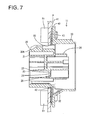
- the housing 11 is made e.g. of synthetic resin and, as shown in FIG. 7 , includes a mounting plate 40 to be fixedly mounted (particularly bolted) to the body part (particularly the outer panel) P, an inner tube portion 20 (as a particular first tube portion) integrally or unitarily formed to the mounting plate 40 in such a manner as to penetrate through the mounting plate 40, and an outer tube portion 30 (as a particular second tube portion) at least partly surrounding the outer periphery of the inner tube portion 20 (particularly over at least part of the longitudinal extension and/or over the entire circumference of the first tube portion 20) in such a manner as to substantially project toward the inside of the vehicle (rear side) from the mounting plate 40 and have an open projecting end.
- a mounting plate 40 to be fixedly mounted (particularly bolted) to the body part (particularly the outer panel) P
- an inner tube portion 20 (as a particular first tube portion) integrally or unitarily formed to the mounting plate 40 in such a manner as to penetrate through the mounting plate 40
- At least one lock portion 12 is provided on the outer or upper surface of a receptacle 20A of the inner tube portion 20 to be described later.
- a lock arm (not shown) provided in the charging connector is engageable with this lock portion 12, and the charging connector and the vehicle-side connector 10 are held in a connected state to perform charging by the engagement of the lock portion 12 and the lock arm in forward and backward directions.
- the inner tube portion 20 includes the receptacle 20A particularly substantially having a cylindrical or tubular shape.
- the (particularly substantially cylindrical or tubular) receptacle 20A substantially projects forward from the mounting plate 40.
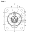
- a (particularly substantially cylindrical or tubular) terminal accommodating portion 21 in which the one or more terminal fittings 60 are to be at least partly accommodated is provided in the receptacle 20A.
- the terminal accommodating portion 21 particularly is formed with two types of larger and smaller (particularly substantially cylindrical or tubular) portions 22 which substantially are annularly arranged, and/or the adjacent (cylindrical or tubular) portions 22 are coupled to each other.
- the terminal accommodating portion 21 and the respective cylindrical portions 22 substantially project in forward and backward directions through the mounting plate 40.
- a partition wall 23 for partitioning the internal space into front and rear sides is provided in an intermediate part (particularly substantially in a central part) of each cylindrical portion 22, and a terminal insertion hole 24 for allowing insertion of a terminal connecting portion 61 of the terminal fitting 60 to be described later is formed in this partition wall 23. Further, at least one escape hole 25 for allowing water or any other liquid having entered the cylindrical portion 22 from front to escape to the rear side is formed substantially below the terminal insertion hole 24 in the partition wall 23.
- a drain plate 27 in the form of a downwardly inclined (particularly substantially flat) plate is connected to the lower side of each cylindrical portion 22 behind the mounting plate 40.
- This drain plate 27 is connected to the outer periphery of the terminal accommodating portion 21.
- the drain plate 27 is inclined downwardly from the lower edge of the escape hole 25 and connected to the outer periphery of the terminal accommodating portion 21.
- water or any other liquid can be drained from the escape hole 25 to an outer peripheral side of the terminal accommodating portion 21 along the upper surface of the drain plate 27.
- the mounting plate 40 bulges out radially outwardly from the outer peripheral surface of the inner tube portion 20 and/or particularly substantially has a substantially rectangular outer shape.
- one or more (particularly metal) collars 41 are press-fitted on respective (e.g. four) corners of the mounting plate 40. Both ends (inner and/or outer) of the collars 41 project from surfaces of the mounting plate 40.
- At least one drain port 42 is formed to penetrate through the mounting plate 40 substantially below the inner tube portion 20.
- a mounting groove 43 which at least partly surrounds the inner tube portion 20 and the drain port 42 together is formed by recessing the front surface of the mounting plate 40.
- This mounting groove 43 is shaped to substantially extend downwardly while circumventing the drain port 42.
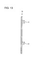
- the rubber ring 50 is so shaped that a lower end portion substantially extends downwardly as shown in FIG. 12 .
- the rubber ring 50 (as a particular seal ring) made of a resilient material such as rubber is mounted into the mounting groove 43.
- a resilient material such as rubber
- FIG. 6 one or more, particularly a plurality of insertion holes 44 are formed in the bottom surface of the mounting groove 43 particularly while substantially being circumferentially spaced apart.
- One or more, particularly a plurality of insertion pieces 51 provided on the rubber ring 50 as shown in FIG. 13 are to be at least partly inserted into these insertion holes 44, whereby the rubber ring 50 is held and retained in the mounting groove 43.
- the terminal fitting 60 is formed by press-working (particularly bending, folding and/or embossing) an electrically conductive (particularly metal) flat plate and, as shown in FIG. 1 or 5 , includes the terminal connecting portion 61 (particularly substantially in the form of a round bar), a wire connecting portion 62 provided behind the terminal connecting portion 61, and a front stop portion 63 particularly formed between the terminal connecting portion 61 and the wire connecting portion 62.
- the terminal connecting portion 61 substantially matches the terminal insertion hole 24 in the (particularly cylindrical) portion 22 and at least partly is insertable thereinto.
- the front stop portion 63 comes into contact with the partition wall 23 (particularly substantially from behind) to stop the terminal fitting 60 at its proper position (particularly at its front end position).
- the wire connecting portion 62 has a cylindrical shape with an open rear end and is to be connected (particularly crimped, bent or folded and connected) to a core exposed at an end of a wire W (particularly such as by hexagonal crimping).
- One or more, particularly a plurality of retaining projections 26 are provided on the outer peripheral surface of the inner tube portion 20.
- one or more, particularly a plurality of retaining pieces 71 engageable with the respective retaining projection(s) 26 in forward and backward directions FBD are provided on the peripheral wall of the retainer 70.
- the retainer 70 includes one or more contact portions 72 which are to be at least partly inserted into the cylindrical portion(s) 22 to be brought into contact with the (front) stop portion(s) 63 from behind. In this way, the retainer 70 is fixed to the inner tube portion 20 and the respective terminal fitting(s) 60 is/are retained so as not to come out e.g. backward by the respective contact portion(s) 72 in a state where the (particularly plurality of) retaining piece(s) 71 is/are engaged with the (particularly plurality of) retaining projection(s) 26.
- the outer tube portion 30 particularly substantially has a cylindrical outer shape one size larger than the inner tube portion 20 and/or is arranged coaxially with the inner tube portion 20.
- the rear end of the outer tube portion 30 particularly is located behind that of the inner tube portion 20.
- one or more, particularly a plurality of locking projections 31 are provided on the outer peripheral surface of the outer tube portion 30.
- at least one drain channel 32 connected to the drain port 42 is provided at the inner lower surface of the outer tube portion 30.
- the drain channel 32 particularly has such a tapered shape as to be enlarged downwardly toward the mounting plate 40.
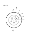
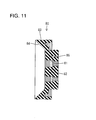
- the rubber plug 80 (as a particular resilient plug) is made of a resilient material such as rubber and, as shown in FIGS. 10 and 11 , includes a base plate portion 82 formed with one or more, particularly a plurality of seal holes 81 through which one or more wires W are to be inserted in a sealed state (wherein the seal holes 81 particularly come in two larger and smaller sizes and through which two types of larger and smaller wires W are to be inserted in a sealed state), and a tapered peripheral wall portion 83 standing from the peripheral edge of the base plate portion 82.
- the (particularly each) seal hole 81 penetrates through the base plate portion 82 substantially in forward and backward directions FBD (plate thickness direction) and particularly is composed of or comprises a large-diameter hole or portion arranged at a front side and a small-diameter hole or portion arranged at a rear side.
- the wire connecting portion 62 of the terminal fitting 60 is to be at least partly accommodated in a sealed state in (particularly the large-diameter hole of) the seal hole 81 and the wire W is accommodated in a sealed state in (particularly the small-diameter hole of) the seal hole 81.
- one or more, particularly a plurality of annular lip portions are circumferentially provided in the seal hole 81, and these lip portions are squeezed (particularly substantially over the entire circumference) by the wire connecting portion 62 and the wire W, whereby a sealing function is fulfilled.
- the front surface of the peripheral wall portion 83 particularly is or comprises an inclined surface 84 extending radially outwardly toward the front side.
- This inclined surface 84 particularly substantially has a truncated conical shape over the entire circumference and, as shown in FIG. 5 , is connected to the drain channel 32 of the outer tube portion 30 in a state where the rubber plug 80 is mounted in the housing 11. That is, the rubber plug 80 is so mounted into the housing 11 that the rear end of the drain channel 32 is connected or corresponds to the front end of the inclined surface 84.
- an angle of inclination of the inclined surface 84 particularly is somewhat larger than that of the drain channel 32.
- one or more, particularly a plurality of annular lip portions particularly are circumferentially provided on the outer peripheral surface of the peripheral wall portion 83. These lip portions substantially are squeezed over the entire circumference by the inner peripheral surface of the outer tube portion 30 as shown in FIG. 5 , whereby a sealing function is fulfilled.
- a sealed space 33 is formed in the outer tube portion 30.
- This sealed space 33 particularly is formed by the inner peripheral surface of the outer tube portion 30, the outer peripheral surface of the inner tube portion 20, the inclined surface 84 of the rubber plug 80 and the like. Since the sealed space 33 substantially communicates with the atmosphere through the drain port 42, the internal pressure of the sealed space 33 can be made substantially equal to an atmospheric pressure.
- a mold removal hole 45 left in forming the lock portion 12 particularly is formed above the inner tube portion 20 in the mounting plate 40, and the sealed space 33 communicates with the atmosphere also by this mold removal hole 45.
- a positioning hole 86 is formed in the rear surface of the peripheral wall portion 83 as shown in FIG. 11 .
- at least one positioning projection 94 provided on the plug holder (rubber plug presser) 90 is press-fitted into this positioning hole 86. Further, forward and backward movements of the rubber plug 80 particularly are prevented by mounting the base plate portion 82 between the retainer 70 and the rubber plug presser 90 in forward and backward directions FBD substantially without forming any clearance.
- the rubber plug presser 90 (as a particular plug holder) is made e.g. of synthetic resin and, as shown in FIG. 14 , includes a pressing portion 92 formed with one or more, particularly a plurality of wire insertion holes 96 (which particularly come in two larger and smaller sizes), and an outer wall portion 93 standing or projecting from the peripheral edge of the pressing portion 92.
- the one or more respective wire insertion holes 96 are arranged to substantially correspond to the one or more respective seal holes 81 of the rubber plug 80 and the one or more wires W pulled out backward from the respective seal holes 81 can be inserted through the wire insertion holes 96.
- the positioning projection 94 for positioning the rubber plug 80 in a circumferential direction particularly is provided on the front surface of the pressing portion 92. This positioning projection 94 particularly is press-fitted into the positioning hole 96 formed in the rear surface of the base plate portion 82 of the rubber plug 80.
- one or more, particularly a plurality of locking pieces 95 are provided on the outer wall portion 93. These locking pieces 95 are to be engaged with the corresponding locking projections 31 of the outer tube portion 30 in forward and backward directions FBD when the rubber plug presser 90 is mounted into or to the housing 11. In this way, the rubber plug presser 90 is held or positioned at the rear end opening of the outer tube portion 30 and the rubber plug 80 is held and retained in the outer tube portion 30, particularly in a slightly compressed state.
- FIG. 3 if water or any other fluid or liquid enters (any of) a pair of left and right larger cylindrical portions 22 arranged in an upper part in the terminal accommodating portion 21, this water enters the sealed space 33 through the escape holes 25 of the partition walls 23.
- the water having entered the sealed space 33 is guided obliquely downwardly toward the outer periphery of the terminal accommodating portion 21 via the one or more drain plates 27 and brought to the drain channel 32 along the inclined surface 84 of the rubber plug 80.
- the water brought to the drain channel 32 is drained to the outside of the vehicle through the drain port 42. Accordingly, the water or other liquid can be drained through this drain or drainage path DP1.
- the wire connecting portion(s) 62 of the terminal fitting(s) 60 is/are connected (particularly crimped, bent or folded and connected) to the core(s) of the wire(s) W and the terminal fitting(s) 60 is/are at least partly inserted into the cylindrical portion(s) 22 particularly substantially from behind.
- the (front) stop portion(s) 63 of the terminal fitting(s) 60 come(s) into contact with the partition wall(s) 23 particularly substantially from behind, whereby the terminal fitting(s) 60 are positioned or stopped at their propoer position(s), particularly at their front end position(s).
- the retainer 70 is mounted into or to (particularly the rear end opening of) the terminal accommodating portion 21 from behind.
- the contact portion(s) 72 at least partly is/are inserted into the cylindrical portion(s) 22 (particularly substantially from behind) and brought into contact with the rear surface(s) of the (front) stop portion(s) 63.
- the retaining piece(s) 71 particularly is/are engaged with the retaining projection(s) 26, whereby the retainer 70 is held at (particularly the rear end opening of) the terminal accommodating portion 21. In this way, the terminal fitting(s) 60 is/are held and retained in the cylindrical portion(s) 22.
- the rubber plug 80 (as a particular resilient plug) mounted on the wire(s) W in advance is mounted into the outer tube portion 30 from behind and the rubber plug presser 90 (as a particular plug holder) is mounted into or to (particularly the rear end opening of) the outer tube portion 30. In this way, the rubber plug 80 is held in the outer tube portion 30 to form the sealed space 33.
- the charging connector In charging the battery of the vehicle, the charging connector is or can be connected to the vehicle-side connector 10. At this time, a small connecting force is sufficient since the air in the sealed space 33 escapes to the outside of the vehicle through the drain port 42. Rainwater may splash on the vehicle-side connector 10 at the time of charging and/or an electrically conductive liquid may splash on the vehicle-side connector 10 at the time of washing the vehicle. In such cases, it is necessary to quickly drain liquid, rainwater or the like having splashed on the vehicle-side connector 10 to the outside of the vehicle.
- the first drain path DP1 particularly is a path passing the escape holes 25, the drain plates 27, the drain channel 32 and the like.
- the second drain path DP2 particularly is a path passing the escape holes 25, the inclined surface 84, the drain channel 32 and the like. In this way, the water or any other liquid in the cylindrical portions 22 is quickly discharged to the outside of the vehicle.
- the outer tube portion 30 is provided at the vehicle inner side of the mounting plate 40 and the rubber plug 80 is mounted into or to (particularly the rear end opening of) this outer tube portion 30, whereby the sealed space 33 is formed in the outer tube portion 30 and water having entered the sealed space 33 can be drained to the outside of the vehicle along the inclined surface 84 of the rubber plug 80 and the drain channel 32. Further, the reverse flow of water from the drain port 42 into the sealed space 33 particularly can be avoided. In this way, the entrance of water into the inside of the vehicle particularly can be avoided and water in the sealed space 33 can be reliably drained to the outside of the vehicle through the drain port 42.
- the base plate portion 82 of the rubber plug 80 particularly is arranged between the retainer 70 and the pressing portion 92 of the rubber plug presser 90, the rubber plug 80 can be reliably held without moving in forward and backward directions FBD.
- a vehicle-side connector 10 includes a mounting plate 40 which is to be fixed to an outer panel or body part P of a vehicle, an inner tube portion 20 which is so provided at the mounting plate 40 as to penetrate through the mounting plate 40, an outer tube portion 30 (which particularly at least partly surrounds an outer peripheral side of the inner tube portion 20 over the entire circumference) in such a manner as to project from the mounting plate 40 toward the inside of the vehicle and have an open projecting end, a rubber plug 80 (as a particular resilient plug) which forms a sealed space 33 in the outer tube portion 30 by sealing between wire(s) W pulled into the inside of the vehicle from the interior of the inner tube portion 20 and an opening of the outer tube portion 30, a rubber plug presser 90 (as a particular plug holder) which is mounted to the outer tube portion 30 (particularly at least partly in the opening of the outer tube portion 30) to retain the rubber plug 80, an inclined surface
Abstract
Description
- The present invention relates to a vehicle-side connector to be connected to a charging connector at the time of charging and to a mounting method therefor.
- A vehicle-side connector of this type is, for example, known from Japanese Unexamined Patent Publication No.
H07-29631 - However, since the above drain port is arranged in the housing chamber and the drain hose connected to this drain port is arranged closer to the inside of the vehicle than the body, a battery may be wetted by water drained from the drain hose in the case of a vehicle type in which the battery is disposed below the housing chamber. Further, a pressure difference is created between the inside of the vehicle and the housing chamber, and the water in the drain hose may flow back to the housing chamber due to this pressure difference.
- The present invention was completed in view of the above situation and an object thereof is to improve drainage properties of a connector.
- This object is solved according to the invention by the features of the independent claims. Particular embodiments of the invention are subject of the dependent claims.
- Accordingly, drainage properties are improved by preventing the reverse flow of drained fluid, liquid or water by draining fluid, liquid or water having entered a vehicle-side connector to the outside of a vehicle.
- According to one aspect of the invention, there is provided a vehicle-side connector to be connected to a charging connector at the time of charging, comprising: a mounting plate which is to be fixed to a body part of a vehicle; a first tube portion which is so provided at the mounting plate as to at least partly penetrate through the mounting plate; a second tube portion projecting from the mounting plate toward the inside of the vehicle and have an open projecting end; a resilient plug which forms a sealed space in the second tube portion by sealing between a wire pulled into the inside of the vehicle from the interior of the first tube portion and an opening of the second tube portion; a plug holder which is mounted to the second tube portion to retain the resilient plug; at least one fluid guide portion which is provided in the sealed space and inclined downwardly toward the outside of the vehicle; and at least one drain port which penetrates though the mounting plate and drains fluid from the fluid guide portion to the outside of the vehicle.
- According to this configuration, it is possible to form the sealed space in the second tube portion, bring liquid or fluid in this sealed space to the drain port by the liquid guide portion and drain the liquid to the outside of the vehicle from the drain port by mounting the resilient to the second tube portion. Further, since the sealed space communicates with the atmosphere through the drain port, the reverse flow of liquid or water from the drain port into the sealed space can be prevented regardless of a pressure variation inside the vehicle.
- According to a particular embodiment, the second tube portion at least partly surrounds an outer peripheral side of the first tube portion over the entire circumference.
- Particularly, the plug holder is mounted in the opening of the second tube portion to retain the resilient plug.
- According to a further particular embodiment, there is provided a vehicle-side connector to be connected to a charging connector at the time of charging, comprising a mounting plate which is to be fixed to a body of a vehicle; an inner tube portion which is so provided at the mounting plate as to penetrate through the mounting plate; an outer tube portion which surrounds an outer peripheral side of the inner tube portion over the entire circumference in such a manner as to project from the mounting plate toward the inside of the vehicle and have an open projecting end; a rubber plug which forms a sealed space in the outer tube portion by sealing between a wire pulled into the inside of the vehicle from the interior of the inner tube portion and an opening of the outer tube portion; a rubber plug presser which is mounted in the opening of the outer tube portion to retain the rubber plug; a water guide portion which is provided in the sealed space and inclined downwardly toward the outside of the vehicle; and a drain port which penetrates though the mounting plate and drains water from the water guide portion to the outside of the vehicle.
- According to this configuration, it is possible to form the sealed space in the outer tube portion, bring water in this sealed space to the drain port by the water guide portion and drain the water to the outside of the vehicle from the drain port by mounting the rubber plug in the opening of the outer tube portion. Further, since the sealed space communicates with the atmosphere through the drain port, the reverse flow of water from the drain port into the sealed space can be prevented regardless of a pressure variation inside the vehicle.
- The following configurations are preferable as embodiments of the present invention.
- The vehicle-side connector may further comprise at least one terminal fitting which is or is to be connected to an end of the wire and at least partly accommodated in the first tube portion (particularly the inner tube portion), and a retainer which is mounted to the first tube portion, particularly at least partly in an opening of the first (inner) tube portion, to retain the terminal fitting(s).
- The resilient plug (particularly the rubber plug) may include a base plate portion formed with at least one seal hole through which the wire is inserted in a sealed state.
- By doing so, the resilient plug (rubber plug) can be more easily fixed particularly by at least partly arranging the base plate portion of the resilient plug (rubber plug) between the retainer and the plug holder (particularly the rubber plug presser).
- The resilient plug (rubber plug) may include a peripheral wall portion particularly being tapered and standing from the peripheral edge of the base plate portion.
- The fluid (water) guide portion may be provided from the peripheral wall portion to the second (particularly outer) tube portion.
- If the fluid (water) guide portion is provided only in the second (outer) tube portion without providing the resilient (rubber) plug with the peripheral wall portion, a long fluid (water) guide portion needs to be formed from the opening of the outer tube portion to the mounting plate and the position of the drain port is located more downward (more away from the first or inner tube portion), wherefore the mounting plate tends to become longer in a downward direction. In this respect, since the resilient (rubber) plug is provided with the (particularly tapered) peripheral wall portion and the fluid (water) guide portion is formed from this peripheral wall portion to the second (outer) tube portion according to the above configuration, the fluid (water) guide portion in the second (outer) tube portion can be made shorter, with the result that the position of the drain port can be located more upward (closer to the inner tube portion) and the mounting plate can be made shorter in a vertical direction.
- Forward and backward movements of the resilient plug may be prevented by mounting the base plate portion between the retainer and the plug holder in forward and backward directions substantially without forming any clearance.
- The fluid guide portion may comprise a portion having a tapered shape as to be enlarged downwardly toward the mounting plate.
- Fluid having entered a portion of the first tube portion and reached the sealed space may be guided obliquely downwardly via one or more drain plates and brought to a drain channel along an inclined surface of the resilient plug and then drained to the outside of the vehicle through the drain port.
- According to a further aspect of the invention, there is provided a mounting or assembling method for a vehicle-side connector, in particular according to the above aspect of the invention or a particular embodiment thereof, to be connected to a charging connector at the time of charging, comprising the following steps: fixing a mounting plate to a body part of a vehicle; providing an first tube portion at the mounting plate as to at least partly penetrate through the mounting plate; providing a second tube portion projecting from the mounting plate toward the inside of the vehicle and have an open projecting end; mounting a resilient plug such as to form a sealed space in the second tube portion by sealing between a wire pulled into the inside of the vehicle from the interior of the first tube portion and an opening of the second tube portion; mounting a plug holder to the second tube portion to retain the resilient plug; providing at least one fluid guide portion in the sealed space and inclined downwardly toward the outside of the vehicle; and providing at least one drain port which penetrates though the mounting plate and drains fluid from the fluid guide portion to the outside of the vehicle.
- According to a particular embodiment, the second tube portion may be provided so as to at least partly surround an outer peripheral side of the first tube portion over the entire circumference.
- Particularly, the plug holder may be mounted in the opening of the second tube portion to retain the resilient plug.
- The method particularly may further comprise the following steps: connecting at least one terminal fitting to an end of the wire and at least partly accommodated in the first tube portion; and mounting a retainer in an opening of the first tube portion to retain the terminal fitting.
- Further particularly, the resilient plug may include a base plate portion formed with at least one seal hole through which the wire is inserted in a sealed state, wherein forward and backward movements of the resilient plug preferably are prevented by mounting the base plate portion between the retainer and the plug holder in forward and backward directions substantially without forming any clearance.
- According to the above, it is possible to prevent the reverse flow of fluid, liquid ir water from a drain port to a sealed space by draining fluid, liquid or water having entered a vehicle-side connector to the outside of a vehicle.
- These and other objects, features and advantages of the present invention will become more apparent upon reading of the following detailed description of preferred embodiments and accompanying drawings. It should be understood that even though embodiments are separately described, single features thereof may be combined to additional embodiments.
-
FIG. 1 is an exploded perspective view of a vehicle-side connector in an embodiment, -
FIG. 2 is a perspective view of the vehicle-side connector, -
FIG. 3 is a perspective view party in section showing an example of a drainage structure via drain plates, -
FIG. 4 is a perspective view party in section showing an example of a drainage structure without via the drain plates, -
FIG. 5 is a section showing the internal structure of the vehicle-side connector fixed to an outer panel when viewed sideways, -
FIG. 6 is a front view of a housing, -
FIG. 7 is a section along A-A ofFIG. 6 , -
FIG. 8 is a side view of the housing, -
FIG. 9 is a rear view of the housing, -
FIG. 10 is a front view of a rubber plug, -
FIG. 11 is a section along B-B ofFIG. 10 , -
FIG. 12 is a front view of a rubber ring, -
FIG. 13 is a side view of the rubber ring, -
FIG. 14 is a front view of a rubber plug presser, -
FIG. 15 is a section along C-C ofFIG. 14 , -
FIG. 16 is a section along D-D ofFIG. 14 , -
FIG. 17 is a side view of the rubber plug presser, -
FIG. 18 is a front view of a retainer, -
FIG. 19 is a section along E-E ofFIG. 18 , and -
FIG. 20 is a side view of the retainer. - A particular embodiment of the present invention is described with reference to
FIGS. 1 to 20 . A vehicle-side connector 10 in this embodiment is to be connected to a battery (not shown) installed in an electric vehicle, a hybrid vehicle or the like, and is connected to a charging connector (not shown) at the time of charging into this battery. As shown inFIG. 5 , the vehicle-side connector 10 includes ahousing 11 to be fastened to a body part (such as an outer panel P forming a body) of the vehicle particularly by one or more bolts B1. A mounting hole B2 is formed in the body part (particularly outer panel) P and thehousing 11 is to be mounted and fixed to the body part (outer panel) P through this mounting hole B2. - As shown in
FIG. 1 , the vehicle-side connector 10 includes thehousing 11, a rubber ring 50 (as a particular sealing ring) to be mounted on the front side (frontal side) of thehousing 11, one or moreterminal fittings 60 to be at least partly accommodated in thehousing 11, particularly aretainer 70 to be mounted on or to (particularly the back side (or rear side) of) thehousing 11, a rubber plug 80 (as a particular resilient plug) to be mounted on the back side of theretainer 70 and a rubber plug presser 90 (as a particular plug holder) to be mounted to thehousing 11 to hold therubber plug 80, particularly on the back side of therubber plug 80. - The
housing 11 is made e.g. of synthetic resin and, as shown inFIG. 7 , includes a mountingplate 40 to be fixedly mounted (particularly bolted) to the body part (particularly the outer panel) P, an inner tube portion 20 (as a particular first tube portion) integrally or unitarily formed to the mountingplate 40 in such a manner as to penetrate through the mountingplate 40, and an outer tube portion 30 (as a particular second tube portion) at least partly surrounding the outer periphery of the inner tube portion 20 (particularly over at least part of the longitudinal extension and/or over the entire circumference of the first tube portion 20) in such a manner as to substantially project toward the inside of the vehicle (rear side) from the mountingplate 40 and have an open projecting end. At least onelock portion 12 is provided on the outer or upper surface of areceptacle 20A of theinner tube portion 20 to be described later. A lock arm (not shown) provided in the charging connector is engageable with thislock portion 12, and the charging connector and the vehicle-side connector 10 are held in a connected state to perform charging by the engagement of thelock portion 12 and the lock arm in forward and backward directions. - The
inner tube portion 20 includes thereceptacle 20A particularly substantially having a cylindrical or tubular shape. The (particularly substantially cylindrical or tubular) receptacle 20A substantially projects forward from the mountingplate 40. A (particularly substantially cylindrical or tubular)terminal accommodating portion 21 in which the one or moreterminal fittings 60 are to be at least partly accommodated is provided in thereceptacle 20A. Theterminal accommodating portion 21 particularly is formed with two types of larger and smaller (particularly substantially cylindrical or tubular)portions 22 which substantially are annularly arranged, and/or the adjacent (cylindrical or tubular)portions 22 are coupled to each other. Theterminal accommodating portion 21 and the respectivecylindrical portions 22 substantially project in forward and backward directions through the mountingplate 40. - A
partition wall 23 for partitioning the internal space into front and rear sides is provided in an intermediate part (particularly substantially in a central part) of eachcylindrical portion 22, and aterminal insertion hole 24 for allowing insertion of aterminal connecting portion 61 of the terminal fitting 60 to be described later is formed in thispartition wall 23. Further, at least oneescape hole 25 for allowing water or any other liquid having entered thecylindrical portion 22 from front to escape to the rear side is formed substantially below theterminal insertion hole 24 in thepartition wall 23. - As shown in
FIG. 9 , adrain plate 27 in the form of a downwardly inclined (particularly substantially flat) plate is connected to the lower side of eachcylindrical portion 22 behind the mountingplate 40. Thisdrain plate 27 is connected to the outer periphery of theterminal accommodating portion 21. Further, thedrain plate 27 is inclined downwardly from the lower edge of theescape hole 25 and connected to the outer periphery of theterminal accommodating portion 21. Thus, water or any other liquid can be drained from theescape hole 25 to an outer peripheral side of theterminal accommodating portion 21 along the upper surface of thedrain plate 27. - As shown in
FIG. 6 , the mountingplate 40 bulges out radially outwardly from the outer peripheral surface of theinner tube portion 20 and/or particularly substantially has a substantially rectangular outer shape. Specifically, one or more (particularly metal)collars 41 are press-fitted on respective (e.g. four) corners of the mountingplate 40. Both ends (inner and/or outer) of thecollars 41 project from surfaces of the mountingplate 40. Thus, when thehousing 11 is fixed (particularly bolted or riveted) to the outer panel P, thecollars 41 are brought into direct contact with the outer panel P and thehousing 11 is firmly fixed to the outer panel P. - At least one
drain port 42 is formed to penetrate through the mountingplate 40 substantially below theinner tube portion 20. A mountinggroove 43 which at least partly surrounds theinner tube portion 20 and thedrain port 42 together is formed by recessing the front surface of the mountingplate 40. This mountinggroove 43 is shaped to substantially extend downwardly while circumventing thedrain port 42. In conformity with this, therubber ring 50 is so shaped that a lower end portion substantially extends downwardly as shown inFIG. 12 . - The rubber ring 50 (as a particular seal ring) made of a resilient material such as rubber is mounted into the mounting
groove 43. As shown inFIG. 6 , one or more, particularly a plurality of insertion holes 44 are formed in the bottom surface of the mountinggroove 43 particularly while substantially being circumferentially spaced apart. One or more, particularly a plurality ofinsertion pieces 51 provided on therubber ring 50 as shown inFIG. 13 are to be at least partly inserted into these insertion holes 44, whereby therubber ring 50 is held and retained in the mountinggroove 43. - The
terminal fitting 60 is formed by press-working (particularly bending, folding and/or embossing) an electrically conductive (particularly metal) flat plate and, as shown inFIG. 1 or5 , includes the terminal connecting portion 61 (particularly substantially in the form of a round bar), awire connecting portion 62 provided behind theterminal connecting portion 61, and afront stop portion 63 particularly formed between theterminal connecting portion 61 and thewire connecting portion 62. Theterminal connecting portion 61 substantially matches theterminal insertion hole 24 in the (particularly cylindrical)portion 22 and at least partly is insertable thereinto. Thefront stop portion 63 comes into contact with the partition wall 23 (particularly substantially from behind) to stop the terminal fitting 60 at its proper position (particularly at its front end position). Thewire connecting portion 62 has a cylindrical shape with an open rear end and is to be connected (particularly crimped, bent or folded and connected) to a core exposed at an end of a wire W (particularly such as by hexagonal crimping). - One or more, particularly a plurality of retaining
projections 26 are provided on the outer peripheral surface of theinner tube portion 20. On the other hand, as shown inFIGS. 18 to 20 , one or more, particularly a plurality of retainingpieces 71 engageable with the respective retaining projection(s) 26 in forward and backward directions FBD are provided on the peripheral wall of theretainer 70. Further, theretainer 70 includes one ormore contact portions 72 which are to be at least partly inserted into the cylindrical portion(s) 22 to be brought into contact with the (front) stop portion(s) 63 from behind. In this way, theretainer 70 is fixed to theinner tube portion 20 and the respective terminal fitting(s) 60 is/are retained so as not to come out e.g. backward by the respective contact portion(s) 72 in a state where the (particularly plurality of) retaining piece(s) 71 is/are engaged with the (particularly plurality of) retaining projection(s) 26. - The
outer tube portion 30 particularly substantially has a cylindrical outer shape one size larger than theinner tube portion 20 and/or is arranged coaxially with theinner tube portion 20. The rear end of theouter tube portion 30 particularly is located behind that of theinner tube portion 20. As shown inFIG. 8 , one or more, particularly a plurality of lockingprojections 31 are provided on the outer peripheral surface of theouter tube portion 30. On the other hand, as shown inFIG. 7 , at least onedrain channel 32 connected to thedrain port 42 is provided at the inner lower surface of theouter tube portion 30. Thedrain channel 32 particularly has such a tapered shape as to be enlarged downwardly toward the mountingplate 40. - The rubber plug 80 (as a particular resilient plug) is made of a resilient material such as rubber and, as shown in
FIGS. 10 and11 , includes abase plate portion 82 formed with one or more, particularly a plurality of seal holes 81 through which one or more wires W are to be inserted in a sealed state (wherein the seal holes 81 particularly come in two larger and smaller sizes and through which two types of larger and smaller wires W are to be inserted in a sealed state), and a taperedperipheral wall portion 83 standing from the peripheral edge of thebase plate portion 82. - As shown in
FIG. 11 , the (particularly each)seal hole 81 penetrates through thebase plate portion 82 substantially in forward and backward directions FBD (plate thickness direction) and particularly is composed of or comprises a large-diameter hole or portion arranged at a front side and a small-diameter hole or portion arranged at a rear side. Thewire connecting portion 62 of the terminal fitting 60 is to be at least partly accommodated in a sealed state in (particularly the large-diameter hole of) theseal hole 81 and the wire W is accommodated in a sealed state in (particularly the small-diameter hole of) theseal hole 81. Note that one or more, particularly a plurality of annular lip portions are circumferentially provided in theseal hole 81, and these lip portions are squeezed (particularly substantially over the entire circumference) by thewire connecting portion 62 and the wire W, whereby a sealing function is fulfilled. - The front surface of the
peripheral wall portion 83 particularly is or comprises aninclined surface 84 extending radially outwardly toward the front side. Thisinclined surface 84 particularly substantially has a truncated conical shape over the entire circumference and, as shown inFIG. 5 , is connected to thedrain channel 32 of theouter tube portion 30 in a state where therubber plug 80 is mounted in thehousing 11. That is, therubber plug 80 is so mounted into thehousing 11 that the rear end of thedrain channel 32 is connected or corresponds to the front end of theinclined surface 84. Note that an angle of inclination of theinclined surface 84 particularly is somewhat larger than that of thedrain channel 32. - As shown in
FIG. 11 , one or more, particularly a plurality of annular lip portions particularly are circumferentially provided on the outer peripheral surface of theperipheral wall portion 83. These lip portions substantially are squeezed over the entire circumference by the inner peripheral surface of theouter tube portion 30 as shown inFIG. 5 , whereby a sealing function is fulfilled. In this way, a sealedspace 33 is formed in theouter tube portion 30. This sealedspace 33 particularly is formed by the inner peripheral surface of theouter tube portion 30, the outer peripheral surface of theinner tube portion 20, theinclined surface 84 of therubber plug 80 and the like. Since the sealedspace 33 substantially communicates with the atmosphere through thedrain port 42, the internal pressure of the sealedspace 33 can be made substantially equal to an atmospheric pressure. Note that amold removal hole 45 left in forming thelock portion 12 particularly is formed above theinner tube portion 20 in the mountingplate 40, and the sealedspace 33 communicates with the atmosphere also by thismold removal hole 45. - A
positioning hole 86 is formed in the rear surface of theperipheral wall portion 83 as shown inFIG. 11 . As shown inFIG. 5 , at least onepositioning projection 94 provided on the plug holder (rubber plug presser) 90 is press-fitted into thispositioning hole 86. Further, forward and backward movements of therubber plug 80 particularly are prevented by mounting thebase plate portion 82 between theretainer 70 and therubber plug presser 90 in forward and backward directions FBD substantially without forming any clearance. - The rubber plug presser 90 (as a particular plug holder) is made e.g. of synthetic resin and, as shown in
FIG. 14 , includes apressing portion 92 formed with one or more, particularly a plurality of wire insertion holes 96 (which particularly come in two larger and smaller sizes), and anouter wall portion 93 standing or projecting from the peripheral edge of thepressing portion 92. The one or more respective wire insertion holes 96 are arranged to substantially correspond to the one or more respective seal holes 81 of therubber plug 80 and the one or more wires W pulled out backward from the respective seal holes 81 can be inserted through the wire insertion holes 96. Note that thepositioning projection 94 for positioning therubber plug 80 in a circumferential direction particularly is provided on the front surface of thepressing portion 92. Thispositioning projection 94 particularly is press-fitted into thepositioning hole 96 formed in the rear surface of thebase plate portion 82 of therubber plug 80. - As shown in
FIGS. 16 and17 , one or more, particularly a plurality of lockingpieces 95 are provided on theouter wall portion 93. These lockingpieces 95 are to be engaged with the corresponding lockingprojections 31 of theouter tube portion 30 in forward and backward directions FBD when therubber plug presser 90 is mounted into or to thehousing 11. In this way, therubber plug presser 90 is held or positioned at the rear end opening of theouter tube portion 30 and therubber plug 80 is held and retained in theouter tube portion 30, particularly in a slightly compressed state. - Here, a drainage structure in the sealed
space 33 is described with reference toFIGS. 3 and4 . First, as shown inFIG. 3 , if water or any other fluid or liquid enters (any of) a pair of left and right largercylindrical portions 22 arranged in an upper part in theterminal accommodating portion 21, this water enters the sealedspace 33 through the escape holes 25 of thepartition walls 23. The water having entered the sealedspace 33 is guided obliquely downwardly toward the outer periphery of theterminal accommodating portion 21 via the one ormore drain plates 27 and brought to thedrain channel 32 along theinclined surface 84 of therubber plug 80. The water brought to thedrain channel 32 is drained to the outside of the vehicle through thedrain port 42. Accordingly, the water or other liquid can be drained through this drain or drainage path DP1. - Next, if water or any other fluid or liquid enters the larger
cylindrical portion 22 e.g. arranged in a lower central part in theterminal accommodating portion 21 as shown inFIG. 4 , this water enters the sealedspace 33 through theescape hole 25 of thepartition wall 23. The water having entered the sealedspace 33 flows downwardly along theinclined surface 84 of therubber plug 80 and drained to the outside of the vehicle through thedrain port 42. Thus, the water or other liquid can be drained through this drain or drainage path DP2. Accordingly, the water having entered the sealedspace 33 does not penetrate to a vehicle inner side of the outer panel P (inside of the vehicle) and is reliably drained to the outside of the vehicle. Thus, it can be prevented that devices such as a battery installed in the vehicle are wetted. Further, since the sealedspace 33 communicates with the atmosphere through thedrain port 42 and the internal pressure of the sealedspace 33 is equal to the atmospheric pressure, there is no possibility of the reverse flow of the water into the sealedspace 33 and the like. - This embodiment is configured as described above. Next, functions of this embodiment are described. First, in assembling the vehicle-
side connector 10, the wire connecting portion(s) 62 of the terminal fitting(s) 60 is/are connected (particularly crimped, bent or folded and connected) to the core(s) of the wire(s) W and the terminal fitting(s) 60 is/are at least partly inserted into the cylindrical portion(s) 22 particularly substantially from behind. Then, the (front) stop portion(s) 63 of the terminal fitting(s) 60 come(s) into contact with the partition wall(s) 23 particularly substantially from behind, whereby the terminal fitting(s) 60 are positioned or stopped at their propoer position(s), particularly at their front end position(s). Thereafter, theretainer 70 is mounted into or to (particularly the rear end opening of) theterminal accommodating portion 21 from behind. In mounting theretainer 70, the contact portion(s) 72 at least partly is/are inserted into the cylindrical portion(s) 22 (particularly substantially from behind) and brought into contact with the rear surface(s) of the (front) stop portion(s) 63. Simultaneously with this, the retaining piece(s) 71 particularly is/are engaged with the retaining projection(s) 26, whereby theretainer 70 is held at (particularly the rear end opening of) theterminal accommodating portion 21. In this way, the terminal fitting(s) 60 is/are held and retained in the cylindrical portion(s) 22. Subsequently, the rubber plug 80 (as a particular resilient plug) mounted on the wire(s) W in advance is mounted into theouter tube portion 30 from behind and the rubber plug presser 90 (as a particular plug holder) is mounted into or to (particularly the rear end opening of) theouter tube portion 30. In this way, therubber plug 80 is held in theouter tube portion 30 to form the sealedspace 33. - In charging the battery of the vehicle, the charging connector is or can be connected to the vehicle-
side connector 10. At this time, a small connecting force is sufficient since the air in the sealedspace 33 escapes to the outside of the vehicle through thedrain port 42. Rainwater may splash on the vehicle-side connector 10 at the time of charging and/or an electrically conductive liquid may splash on the vehicle-side connector 10 at the time of washing the vehicle. In such cases, it is necessary to quickly drain liquid, rainwater or the like having splashed on the vehicle-side connector 10 to the outside of the vehicle. - Accordingly, water pooled or entered in the
cylindrical portions 22 is drained into the sealedspace 33 through the escape holes 25 and the water in the sealedspace 33 is brought to thedrain port 42, for example, by two drain paths DP1, DP2 and drained to the outside of the vehicle from thedrain port 42. The first drain path DP1 particularly is a path passing the escape holes 25, thedrain plates 27, thedrain channel 32 and the like. The second drain path DP2 particularly is a path passing the escape holes 25, theinclined surface 84, thedrain channel 32 and the like. In this way, the water or any other liquid in thecylindrical portions 22 is quickly discharged to the outside of the vehicle. - As described above, in this embodiment, the
outer tube portion 30 is provided at the vehicle inner side of the mountingplate 40 and therubber plug 80 is mounted into or to (particularly the rear end opening of) thisouter tube portion 30, whereby the sealedspace 33 is formed in theouter tube portion 30 and water having entered the sealedspace 33 can be drained to the outside of the vehicle along theinclined surface 84 of therubber plug 80 and thedrain channel 32. Further, the reverse flow of water from thedrain port 42 into the sealedspace 33 particularly can be avoided. In this way, the entrance of water into the inside of the vehicle particularly can be avoided and water in the sealedspace 33 can be reliably drained to the outside of the vehicle through thedrain port 42. - Further, since the
base plate portion 82 of therubber plug 80 particularly is arranged between theretainer 70 and thepressing portion 92 of therubber plug presser 90, therubber plug 80 can be reliably held without moving in forward and backward directions FBD. - Accordingly, to prevent the reverse flow of drained water by draining water having entered a vehicle-side connector to the outside of a vehicle, a vehicle-side connector 10 includes a mounting plate 40 which is to be fixed to an outer panel or body part P of a vehicle, an inner tube portion 20 which is so provided at the mounting plate 40 as to penetrate through the mounting plate 40, an outer tube portion 30 (which particularly at least partly surrounds an outer peripheral side of the inner tube portion 20 over the entire circumference) in such a manner as to project from the mounting plate 40 toward the inside of the vehicle and have an open projecting end, a rubber plug 80 (as a particular resilient plug) which forms a sealed space 33 in the outer tube portion 30 by sealing between wire(s) W pulled into the inside of the vehicle from the interior of the inner tube portion 20 and an opening of the outer tube portion 30, a rubber plug presser 90 (as a particular plug holder) which is mounted to the outer tube portion 30 (particularly at least partly in the opening of the outer tube portion 30) to retain the rubber plug 80, an inclined surface 84 which is provided in the sealed space 33 and inclined downwardly toward the outside of the vehicle, a drain channel 32 and a drain port 42 which penetrates though the mounting plate 40 and drains water from the drain channel 32 to the outside of the vehicle.
- The present invention is not limited to the above described and illustrated embodiment. For example, the following embodiments are also included in the technical scope of the present invention.
- (1) Although a water guide portion is formed by the
inclined surface 84 of therubber plug 80 and thedrain channel 32 of theouter tube portion 30 in the above embodiment, it may be formed only by the drain channel of the outer tube portion according to the present invention. - (2) Although the terminal fitting(s) 60 is/are retained only by the
retainer 70 in the above embodiment, one or more locking lances may be formed in the respective cylindrical portion(s) 22 and the terminal fitting(s) 60 may be retained by the terminal fitting(s) 60 according to the present invention. - (3) Although the
outer tube portion 30 is integrally or unitarily formed to the mountingplate 40 in the above embodiment, the outer tube portion and the mounting plate may be separately formed and connected in a sealed state by a seal ring according to the present invention. Further, although theinner tube portion 20 is integrally or unitarily formed to the mountingplate 40 in the above embodiment, the inner tube portion and the mounting plate may be separately formed and connected in a sealed state by a seal ring according to the present invention. -
- 10 ...
- vehicle-side connector
- 11 ...
- housing
- 20 ...
- inner tube portion (first tube portion)
- 30 ...
- outer tube portion (second tube portion)
- 32 ...
- drain channel (water guide portion)
- 33 ...
- sealed space
- 40 ...
- mounting plate
- 42 ...
- drain port
- 50 ...
- rubber ring (sealing ring)
- 60 ...
- terminal fitting
- 70 ...
- retainer
- 80 ...
- rubber plug (resilient plug)
- 81 ...
- seal hole
- 82 ...
- base plate portion
- 83 ...
- peripheral wall portion
- 84 ...
- inclined surface (water guide portion)
- 90 ...
- rubber plug presser (plug holder)
- P ...
- outer panel (body)
- W ...
- wire
Claims (15)
- A vehicle-side connector (10) to be connected to a charging connector at the time of charging, comprising:a mounting plate (40) which is to be fixed to a body part (P) of a vehicle;a first tube portion (20) which is so provided at the mounting plate (40) as to at least partly penetrate through the mounting plate (40);a second tube portion (30) projecting from the mounting plate (40) toward the inside of the vehicle and have an open projecting end;a resilient plug (80) which forms a sealed space (33) in the second tube portion (30) by sealing between a wire (W) pulled into the inside of the vehicle from the interior of the first tube portion (20) and an opening of the second tube portion (30);a plug holder (90) which is mounted to the second tube portion (30) to retain the resilient plug (80);at least one fluid guide portion (32; 84) which is provided in the sealed space (33) and inclined downwardly toward the outside of the vehicle; andat least one drain port (42) which penetrates though the mounting plate (40) and drains fluid from the fluid guide portion (32; 84) to the outside of the vehicle.
- A vehicle-side connector according to claim 1, wherein the second tube portion (30) at least partly surrounds an outer peripheral side of the first tube portion (20) over the entire circumference.
- A vehicle-side connector according to any one of the preceding claims, wherein the plug holder (90) is mounted in the opening of the second tube portion (30) to retain the resilient plug (80).
- A vehicle-side connector according to any one of the preceding claims, further comprising:at least one terminal fitting (60) which is to be connected to an end of the wire (W) and at least partly accommodated in the first tube portion (20); anda retainer (70) which is mounted in an opening of the first tube portion (20) to retain the terminal fitting (60).
- A vehicle-side connector according to claim 4, wherein the resilient plug (80) includes a base plate portion (82) formed with at least one seal hole (81) through which the wire (W) is inserted in a sealed state.
- A vehicle-side connector according to claim 4 or 5, wherein the resilient plug (80) includes a peripheral wall portion (83) particularly being tapered and standing from the peripheral edge of the base plate portion (82).
- A vehicle-side connector according to claim 6, wherein the fluid guide portion (32; 84) is provided from the peripheral wall portion (83) to the second tube portion (30).
- A vehicle-side connector according to claim 5, 6 or 7, wherein forward and backward movements of the resilient plug (80) are prevented by mounting the base plate portion (82) between the retainer (70) and the plug holder (90) in forward and backward directions (FBD) substantially without forming any clearance.
- A vehicle-side connector according to any one of the preceding claims, wherein the fluid guide portion (32; 84) comprises a portion having a tapered shape as to be enlarged downwardly toward the mounting plate (40).
- A vehicle-side connector according to any one of the preceding claims, wherein fluid having entered a portion (22) of the first tube portion (20) and reached the sealed space (33) is guided obliquely downwardly via one or more drain plates (27) and brought to a drain channel (32) along an inclined surface (84) of the resilient plug (80) and then drained (DP1; DP2) to the outside of the vehicle through the drain port (42).
- A mounting method for a vehicle-side connector (10) to be connected to a charging connector at the time of charging, comprising the following steps:fixing a mounting plate (40) to a body part (P) of a vehicle;providing an first tube portion (20) at the mounting plate (40) as to at least partly penetrate through the mounting plate (40);providing a second tube portion (30) projecting from the mounting plate (40) toward the inside of the vehicle and have an open projecting end;mounting a resilient plug (80) such as to form a sealed space (33) in the second tube portion (30) by sealing between a wire (W) pulled into the inside of the vehicle from the interior of the first tube portion (20) and an opening of the second tube portion (30);mounting a plug holder (90) to the second tube portion (30) to retain the resilient plug (80);providing at least one fluid guide portion (32; 84) in the sealed space (33) and inclined downwardly toward the outside of the vehicle; andproviding at least one drain port (42) which penetrates though the mounting plate (40) and drains fluid from the fluid guide portion (32; 84) to the outside of the vehicle.
- A method according to claim 11, wherein the second tube portion (30) is provided so as to at least partly surround an outer peripheral side of the first tube portion (20) over the entire circumference.
- A method according to claim 11 or 12, wherein the plug holder (90) is mounted in the opening of the second tube portion (30) to retain the resilient plug (80).
- A method according to any one of the preceding claims 11 to 13, further comprising the following steps:connecting at least one terminal fitting (60) to an end of the wire (W) and at least partly accommodated in the first tube portion (20); andmounting a retainer (70) in an opening of the first tube portion (20) to retain the terminal fitting (60).
- A method according to claim 14, wherein the resilient plug (80) includes a base plate portion (82) formed with at least one seal hole (81) through which the wire (W) is inserted in a sealed state, wherein forward and backward movements of the resilient plug (80) preferably are prevented by mounting the base plate portion (82) between the retainer (70) and the plug holder (90) in forward and backward directions (FBD) substantially without forming any clearance.
Applications Claiming Priority (1)
| Application Number | Priority Date | Filing Date | Title |
|---|---|---|---|
| JP2011110686A JP5582093B2 (en) | 2011-05-17 | 2011-05-17 | Vehicle side connector |
Publications (2)
| Publication Number | Publication Date |
|---|---|
| EP2525443A1 true EP2525443A1 (en) | 2012-11-21 |
| EP2525443B1 EP2525443B1 (en) | 2014-01-15 |
Family
ID=45977117
Family Applications (1)
| Application Number | Title | Priority Date | Filing Date |
|---|---|---|---|
| EP12002471.6A Not-in-force EP2525443B1 (en) | 2011-05-17 | 2012-04-05 | Vehicle-side connector and mounting method therefor |
Country Status (3)
| Country | Link |
|---|---|
| US (1) | US8662910B2 (en) |
| EP (1) | EP2525443B1 (en) |
| JP (1) | JP5582093B2 (en) |
Cited By (23)
| Publication number | Priority date | Publication date | Assignee | Title |
|---|---|---|---|---|
| DE102013213336A1 (en) | 2013-07-08 | 2015-01-08 | Tyco Electronics Amp Gmbh | ELECTRICAL CONNECTOR AND CONNECTOR SYSTEM FOR AN ELECTRIC OR HYBRID VEHICLE |
| JP2015158982A (en) * | 2014-02-21 | 2015-09-03 | トヨタ自動車株式会社 | Charging part of vehicle |
| CN105051985A (en) * | 2013-03-19 | 2015-11-11 | 住友电装株式会社 | Vehicle-side connector |
| CN105075026A (en) * | 2013-03-19 | 2015-11-18 | 住友电装株式会社 | Vehicle-side connector |
| CN105144502A (en) * | 2013-03-19 | 2015-12-09 | 住友电装株式会社 | Vehicle-side connector |
| CN105191006A (en) * | 2013-03-19 | 2015-12-23 | 住友电装株式会社 | Vehicle-side connector |
| EP2955796A4 (en) * | 2013-03-19 | 2016-02-24 | Sumitomo Wiring Systems | Vehicle-side connector |
| EP2955795A4 (en) * | 2013-03-19 | 2016-02-24 | Sumitomo Wiring Systems | Vehicle-side connector |
| EP2988374A1 (en) * | 2014-08-22 | 2016-02-24 | Amphenol-tuchel Electronics GmbH | Sealing element for an electrical conductor with stranded conductor |
| CN105576432A (en) * | 2014-10-29 | 2016-05-11 | 日本航空电子工业株式会社 | Connector |
| CN106716732A (en) * | 2014-10-06 | 2017-05-24 | 莫列斯有限公司 | Water resistant connector assembly |
| WO2018206601A1 (en) * | 2017-05-08 | 2018-11-15 | Leoni Bordnetz-Systeme Gmbh | Method for assembling a plug on a multi-core sheathed cable, and electrical plug |
| EP3289641A4 (en) * | 2015-07-15 | 2018-12-05 | Dynomax Inc. | Easily removable contacts for micro connectors |
| WO2018220033A1 (en) * | 2017-05-30 | 2018-12-06 | B. Braun Melsungen Ag | Electric plug connection with dewatering device |
| CN109204064A (en) * | 2017-06-29 | 2019-01-15 | 比亚迪股份有限公司 | Vehicle, external cooling device, charging unit and cooling system of vehicle |
| WO2019106467A1 (en) * | 2017-12-01 | 2019-06-06 | Te Connectivity Corporation | Electrical connector with terminal position assurance member |
| CN109861031A (en) * | 2019-01-09 | 2019-06-07 | 台达电子企业管理(上海)有限公司 | The electrical installation and connector and preparation method of tool electrical connection safeguard function |
| DE102018203967A1 (en) | 2018-03-15 | 2019-09-19 | Bayerische Motoren Werke Aktiengesellschaft | Charging terminal of a vehicle |
| EP3547463A1 (en) * | 2018-03-30 | 2019-10-02 | Yazaki Corporation | Drain structure, terminal block, and on-vehicle device |
| CN110401075A (en) * | 2018-04-25 | 2019-11-01 | 矢崎总业株式会社 | Charge connector |
| US10843582B2 (en) | 2018-10-09 | 2020-11-24 | Phoenix Contact E-Mobility Gmbh | Plug connector part with an inlet part to be connected to a housing part |
| DE102020110640A1 (en) | 2020-04-20 | 2021-10-21 | Amphenol Tuchel Industrial GmbH | Connector system |
| US11374349B2 (en) * | 2019-08-15 | 2022-06-28 | Cheng Uei Precision Industry Co., Ltd. | Receptacle connector device for electric vehicle use |
Families Citing this family (58)
| Publication number | Priority date | Publication date | Assignee | Title |
|---|---|---|---|---|
| JP5923898B2 (en) * | 2011-08-30 | 2016-05-25 | ブラザー工業株式会社 | Development device |
| GB2500012B (en) | 2012-03-06 | 2016-07-06 | Dyson Technology Ltd | A Humidifying Apparatus |
| GB2512192B (en) | 2012-03-06 | 2015-08-05 | Dyson Technology Ltd | A Humidifying Apparatus |
| GB2500017B (en) | 2012-03-06 | 2015-07-29 | Dyson Technology Ltd | A Humidifying Apparatus |
| JP5601355B2 (en) * | 2012-08-01 | 2014-10-08 | トヨタ自動車株式会社 | Inlet assembly |
| JP5981294B2 (en) * | 2012-10-12 | 2016-08-31 | 矢崎総業株式会社 | Charging inlet device |
| DE102012024588B4 (en) | 2012-12-17 | 2023-11-16 | HARTING Automotive GmbH | Connectors |
| AU2014211001B2 (en) | 2013-01-29 | 2016-09-15 | Dyson Technology Limited | A fan assembly |
| EP2942842B1 (en) * | 2013-03-19 | 2017-08-30 | Sumitomo Wiring Systems, Ltd. | Vehicle-side connector |
| US8986019B2 (en) * | 2013-04-22 | 2015-03-24 | Asm Ip Holding B.V. | Connector with air extraction |
| JP6064847B2 (en) * | 2013-09-17 | 2017-01-25 | 株式会社デンソー | Fuel pump |
| US9553440B2 (en) * | 2013-11-18 | 2017-01-24 | Walbro Llc | Wire seal assembly |
| JP6245049B2 (en) | 2014-04-17 | 2017-12-13 | 住友電装株式会社 | Retainer and connector with terminal |
| JP2015213029A (en) | 2014-05-07 | 2015-11-26 | 住友電装株式会社 | Waterproof connector |
| JP2015225771A (en) | 2014-05-28 | 2015-12-14 | 住友電装株式会社 | Inlet for compound type charging |
| JP2016001522A (en) * | 2014-06-11 | 2016-01-07 | 住友電装株式会社 | Inlet for charging |
| JP6448925B2 (en) * | 2014-06-20 | 2019-01-09 | 矢崎総業株式会社 | connector |
| GB2528708B (en) * | 2014-07-29 | 2016-06-29 | Dyson Technology Ltd | A fan assembly |
| JP6201935B2 (en) | 2014-09-02 | 2017-09-27 | 住友電装株式会社 | Vehicle power supply connector |
| DE102014015148B4 (en) | 2014-10-13 | 2018-11-29 | Sumitomo Wiring Systems, Ltd. | Charging connector and method for mounting the same |
| JP6270785B2 (en) * | 2015-07-22 | 2018-01-31 | 矢崎総業株式会社 | Connector mating structure |
| JP6457919B2 (en) * | 2015-11-20 | 2019-01-23 | モレックス エルエルシー | connector |
| CN105691220B (en) * | 2015-12-17 | 2017-12-12 | 云杉智慧新能源技术有限公司 | A kind of charging connection equipment |
| US9583864B1 (en) * | 2016-01-21 | 2017-02-28 | Eaton Corporation | Connection device for electrical connection of an electrical load with a source of electrical power |
| JP2017199582A (en) * | 2016-04-28 | 2017-11-02 | 住友電装株式会社 | Waterproof connector |
| JP6601310B2 (en) * | 2016-05-19 | 2019-11-06 | 住友電装株式会社 | Vehicle side connector |
| JP6593651B2 (en) * | 2016-05-23 | 2019-10-23 | 住友電装株式会社 | connector |
| JP6402145B2 (en) * | 2016-07-13 | 2018-10-10 | 矢崎総業株式会社 | connector |
| WO2018010173A1 (en) * | 2016-07-15 | 2018-01-18 | 华为技术有限公司 | Waterproof communication interface and terminal having waterproof communication interface |
| KR102571704B1 (en) * | 2016-08-17 | 2023-08-30 | 한국단자공업 주식회사 | Connector for charging |
| JP6650115B2 (en) * | 2016-11-02 | 2020-02-19 | 住友電装株式会社 | connector |
| JP2018085172A (en) * | 2016-11-21 | 2018-05-31 | 住友電装株式会社 | Charging inlet |
| CN106450912A (en) * | 2016-11-29 | 2017-02-22 | 安徽江淮汽车集团股份有限公司 | Charging socket assembly |
| US10090659B2 (en) | 2017-02-16 | 2018-10-02 | Bridgeport Fittings, Inc. | Raintight fitting for jacketed metal clad cables |
| JP6769340B2 (en) * | 2017-02-24 | 2020-10-14 | 住友電装株式会社 | Waterproof connector |
| JP6482584B2 (en) * | 2017-03-15 | 2019-03-13 | 矢崎総業株式会社 | connector |
| CN207052838U (en) * | 2017-05-12 | 2018-02-27 | 泰科电子(上海)有限公司 | Seal, seal assembly and socket |
| DE102017223543A1 (en) * | 2017-12-21 | 2019-06-27 | Volkswagen Aktiengesellschaft | Electrical connection element |
| US10355398B1 (en) * | 2018-03-09 | 2019-07-16 | Yazaki North America, Inc. | Vibration limiting compression protrusions |
| JP2020004642A (en) * | 2018-06-29 | 2020-01-09 | 株式会社オートネットワーク技術研究所 | Mounting structure of waterproof connector and waterproof connector |
| KR102571683B1 (en) * | 2018-07-10 | 2023-08-30 | 한국단자공업 주식회사 | Charging receptacle for electric vehicle |
| US10608386B2 (en) * | 2018-08-31 | 2020-03-31 | Erich Jaeger Gmbh + Co. Kg | Socket for connecting a trailer plug connector |
| CN110611278B (en) * | 2018-09-30 | 2021-07-30 | 中航光电科技股份有限公司 | Wire connector |
| JP6923500B2 (en) * | 2018-11-09 | 2021-08-18 | 矢崎総業株式会社 | connector |
| JP2020080268A (en) * | 2018-11-14 | 2020-05-28 | 住友電装株式会社 | connector |
| JP7107859B2 (en) * | 2019-01-25 | 2022-07-27 | トヨタ自動車株式会社 | Fixed structure of charging inlet |
| JP2020149939A (en) * | 2019-03-15 | 2020-09-17 | 矢崎総業株式会社 | Electric wire cover-equipped connector |
| JP6943914B2 (en) * | 2019-03-20 | 2021-10-06 | 矢崎総業株式会社 | Connector with wire cover |
| CA3082605A1 (en) * | 2019-06-08 | 2020-12-08 | Norman R. Byrne | Electrical receptacle with drain-through feature |
| KR102277845B1 (en) * | 2019-06-27 | 2021-07-16 | 한국단자공업 주식회사 | High voltage connector |
| DE102019214955A1 (en) * | 2019-09-30 | 2021-04-01 | Robert Bosch Gmbh | Connector and sealing element for a connector |
| CN110723000B (en) * | 2019-10-08 | 2021-10-08 | 广州小鹏汽车科技有限公司 | Vehicle charging port assembly mounting structure and vehicle |
| KR102307654B1 (en) * | 2020-05-28 | 2021-10-05 | 한국전력공사 | Connector terminal for electric vehicle |
| CN112054352B (en) * | 2020-08-31 | 2022-12-09 | 顺科新能源技术股份有限公司 | Integrated panel |
| FR3125175B1 (en) | 2021-07-06 | 2023-12-15 | Tyco Electronics France Sas | Waterproof cable gland of a pluggable connector |
| CN114122836B (en) * | 2021-11-11 | 2023-09-26 | 盐城市华悦汽车部件有限公司 | Charging port assembly socket with wire harness for electric automobile |
| CN114274810A (en) * | 2021-12-31 | 2022-04-05 | 四川华体照明科技股份有限公司 | Electric vehicle charging monitoring system with early warning function |
| WO2024012687A1 (en) * | 2022-07-14 | 2024-01-18 | Pierburg Gmbh | Charging socket for a charging device for electrically driven vehicles |
Citations (4)
| Publication number | Priority date | Publication date | Assignee | Title |
|---|---|---|---|---|
| US5350312A (en) * | 1992-12-18 | 1994-09-27 | Yazaka Corporation | Feeder connector |
| JPH0729631A (en) * | 1993-07-12 | 1995-01-31 | Sumitomo Wiring Syst Ltd | Drainage structure around connector for charging electric vehicle |
| EP1059697A2 (en) * | 1999-06-10 | 2000-12-13 | Yazaki Corporation | Waterproof connector |
| US20100112841A1 (en) * | 2008-11-05 | 2010-05-06 | Sumitomo Wiring Systems, Ltd. | Connector |
Family Cites Families (15)
| Publication number | Priority date | Publication date | Assignee | Title |
|---|---|---|---|---|
| US4793819A (en) * | 1987-02-20 | 1988-12-27 | Sloan Valve Company | Over-the-road vehicle electrical connector with drain passage |
| US5458496A (en) | 1993-07-12 | 1995-10-17 | Sumitomo Wiring Systems, Ltd. | Charge coupling for electric vehicle |
| JP3433432B2 (en) * | 1993-12-28 | 2003-08-04 | 矢崎総業株式会社 | Power supply connector |
| NO300440B1 (en) * | 1995-05-08 | 1997-05-26 | Defa As | An appliance inlet |
| JP3090005B2 (en) * | 1995-09-21 | 2000-09-18 | 住友電装株式会社 | connector |
| US5800188A (en) * | 1996-02-09 | 1998-09-01 | Joseph Pollak Corporation | Direct connect trailer tow interconnector |
| EP0790671B1 (en) * | 1996-02-09 | 2003-10-22 | Sumitomo Wiring Systems, Ltd. | Connector |
| JP2002112435A (en) * | 2000-09-27 | 2002-04-12 | Sumitomo Wiring Syst Ltd | High voltage electric junction box |
| JP2006339114A (en) * | 2005-06-06 | 2006-12-14 | Yazaki Corp | Connector and waterproof connection member |
| JP4175402B2 (en) * | 2006-07-21 | 2008-11-05 | 松下電工株式会社 | Insulation structure between conductive members in electrical equipment |
| JP5026860B2 (en) * | 2007-05-28 | 2012-09-19 | 矢崎総業株式会社 | Electrical junction box |
| JP5082830B2 (en) * | 2007-12-25 | 2012-11-28 | 住友電装株式会社 | Electrical junction box |
| CN201549679U (en) * | 2009-09-17 | 2010-08-11 | 富士康(昆山)电脑接插件有限公司 | Electric connector |
| JP5370778B2 (en) * | 2010-05-24 | 2013-12-18 | 住友電装株式会社 | Vehicle side connector |
| US8075325B1 (en) * | 2010-11-02 | 2011-12-13 | Standard Cable USA, Inc. | Self-cleaning electrical connection assembly |
-
2011
- 2011-05-17 JP JP2011110686A patent/JP5582093B2/en not_active Expired - Fee Related
-
2012
- 2012-04-05 EP EP12002471.6A patent/EP2525443B1/en not_active Not-in-force
- 2012-05-09 US US13/467,266 patent/US8662910B2/en not_active Expired - Fee Related
Patent Citations (4)
| Publication number | Priority date | Publication date | Assignee | Title |
|---|---|---|---|---|
| US5350312A (en) * | 1992-12-18 | 1994-09-27 | Yazaka Corporation | Feeder connector |
| JPH0729631A (en) * | 1993-07-12 | 1995-01-31 | Sumitomo Wiring Syst Ltd | Drainage structure around connector for charging electric vehicle |
| EP1059697A2 (en) * | 1999-06-10 | 2000-12-13 | Yazaki Corporation | Waterproof connector |
| US20100112841A1 (en) * | 2008-11-05 | 2010-05-06 | Sumitomo Wiring Systems, Ltd. | Connector |
Cited By (51)
| Publication number | Priority date | Publication date | Assignee | Title |
|---|---|---|---|---|
| US9478909B2 (en) | 2013-03-19 | 2016-10-25 | Sumitomo Wiring Systems, Ltd. | Vehicle-side connector |
| CN105075026B (en) * | 2013-03-19 | 2017-10-24 | 住友电装株式会社 | Vehicle-side connector |
| CN105191006B (en) * | 2013-03-19 | 2017-09-15 | 住友电装株式会社 | Vehicle-side connector |
| CN105051985A (en) * | 2013-03-19 | 2015-11-11 | 住友电装株式会社 | Vehicle-side connector |
| CN105075026A (en) * | 2013-03-19 | 2015-11-18 | 住友电装株式会社 | Vehicle-side connector |
| CN105144502A (en) * | 2013-03-19 | 2015-12-09 | 住友电装株式会社 | Vehicle-side connector |
| EP2955794A1 (en) * | 2013-03-19 | 2015-12-16 | Sumitomo Wiring Systems, Ltd. | Vehicle-side connector |
| CN105191006A (en) * | 2013-03-19 | 2015-12-23 | 住友电装株式会社 | Vehicle-side connector |
| EP2955794A4 (en) * | 2013-03-19 | 2015-12-30 | Sumitomo Wiring Systems | Vehicle-side connector |
| EP2955796A4 (en) * | 2013-03-19 | 2016-02-24 | Sumitomo Wiring Systems | Vehicle-side connector |
| EP2955795A4 (en) * | 2013-03-19 | 2016-02-24 | Sumitomo Wiring Systems | Vehicle-side connector |
| CN105144502B (en) * | 2013-03-19 | 2017-07-28 | 住友电装株式会社 | Vehicle-side connector |
| CN105051985B (en) * | 2013-03-19 | 2017-05-24 | 住友电装株式会社 | Vehicle-side connector |
| EP2955793A4 (en) * | 2013-03-19 | 2016-03-02 | Sumitomo Wiring Systems | Vehicle-side connector |
| US9496637B2 (en) | 2013-03-19 | 2016-11-15 | Sumitomo Wiring Systems, Ltd. | Vehicle-side connector |
| CN105359346B (en) * | 2013-07-08 | 2018-09-14 | 泰连德国有限公司 | Electric plug connectors and plug connector system for electric or hybrid vehicle |
| WO2015004053A1 (en) | 2013-07-08 | 2015-01-15 | Tyco Electronics Amp Gmbh | Electrical plug type connector and plug type connector system for an electric or hybrid vehicle |
| DE102013213336B4 (en) | 2013-07-08 | 2024-02-01 | Te Connectivity Germany Gmbh | ELECTRICAL CONNECTOR, CHARGING SOCKET AND CONNECTOR SYSTEM FOR AN ELECTRIC OR HYBRID VEHICLE |
| CN105359346A (en) * | 2013-07-08 | 2016-02-24 | 泰连德国有限公司 | Electrical plug type connector and plug type connector system for an electric or hybrid vehicle |
| DE102013213336A1 (en) | 2013-07-08 | 2015-01-08 | Tyco Electronics Amp Gmbh | ELECTRICAL CONNECTOR AND CONNECTOR SYSTEM FOR AN ELECTRIC OR HYBRID VEHICLE |
| US10044133B2 (en) | 2013-07-08 | 2018-08-07 | Te Connectivity Germany Gmbh | Electrical plug type connector and plug type connector system for an electric or hybrid vehicle |
| JP2015158982A (en) * | 2014-02-21 | 2015-09-03 | トヨタ自動車株式会社 | Charging part of vehicle |
| EP2988374A1 (en) * | 2014-08-22 | 2016-02-24 | Amphenol-tuchel Electronics GmbH | Sealing element for an electrical conductor with stranded conductor |
| CN106716732A (en) * | 2014-10-06 | 2017-05-24 | 莫列斯有限公司 | Water resistant connector assembly |
| CN106716732B (en) * | 2014-10-06 | 2019-07-19 | 莫列斯有限公司 | Water-proof connector component |
| CN105576432B (en) * | 2014-10-29 | 2018-05-11 | 日本航空电子工业株式会社 | Connector |
| CN105576432A (en) * | 2014-10-29 | 2016-05-11 | 日本航空电子工业株式会社 | Connector |
| EP3289641A4 (en) * | 2015-07-15 | 2018-12-05 | Dynomax Inc. | Easily removable contacts for micro connectors |
| CN110603692A (en) * | 2017-05-08 | 2019-12-20 | 莱尼电气系统有限公司 | Method for mounting an electrical connector on a multicore sheathed wire and electrical connector |
| WO2018206601A1 (en) * | 2017-05-08 | 2018-11-15 | Leoni Bordnetz-Systeme Gmbh | Method for assembling a plug on a multi-core sheathed cable, and electrical plug |
| US11309656B2 (en) | 2017-05-08 | 2022-04-19 | Leoni Bordnetz-Systeme Gmbh | Method for assembling a plug on a multi-core sheathed cable, and electrical plug |
| WO2018220033A1 (en) * | 2017-05-30 | 2018-12-06 | B. Braun Melsungen Ag | Electric plug connection with dewatering device |
| CN109204064A (en) * | 2017-06-29 | 2019-01-15 | 比亚迪股份有限公司 | Vehicle, external cooling device, charging unit and cooling system of vehicle |
| US10396486B2 (en) | 2017-12-01 | 2019-08-27 | Te Connectivity India Private Limited | Electrical connector with terminal position assurance member |
| CN111433978A (en) * | 2017-12-01 | 2020-07-17 | 泰连公司 | Electric connector with terminal position assurance member |
| WO2019106467A1 (en) * | 2017-12-01 | 2019-06-06 | Te Connectivity Corporation | Electrical connector with terminal position assurance member |
| CN111433978B (en) * | 2017-12-01 | 2021-12-21 | 泰连公司 | Electric connector with terminal position assurance member |
| DE102018203967A1 (en) | 2018-03-15 | 2019-09-19 | Bayerische Motoren Werke Aktiengesellschaft | Charging terminal of a vehicle |
| CN110323588B (en) * | 2018-03-30 | 2020-12-08 | 矢崎总业株式会社 | Drainage structure, terminal block and on-vehicle device |
| US10644418B2 (en) | 2018-03-30 | 2020-05-05 | Yazaki Corporation | Drain structure, terminal block, and on-vehicle device |
| EP3547463A1 (en) * | 2018-03-30 | 2019-10-02 | Yazaki Corporation | Drain structure, terminal block, and on-vehicle device |
| CN110323588A (en) * | 2018-03-30 | 2019-10-11 | 矢崎总业株式会社 | Discharge structure, terminal block and car-mounted device |
| CN110401075A (en) * | 2018-04-25 | 2019-11-01 | 矢崎总业株式会社 | Charge connector |
| US10843582B2 (en) | 2018-10-09 | 2020-11-24 | Phoenix Contact E-Mobility Gmbh | Plug connector part with an inlet part to be connected to a housing part |
| EP3680988A1 (en) * | 2019-01-09 | 2020-07-15 | Delta Electronics (Shanghai) Co., Ltd. | Electric apparatus with electric connection and protection function, connector and fabricating method thereof |
| CN109861031A (en) * | 2019-01-09 | 2019-06-07 | 台达电子企业管理(上海)有限公司 | The electrical installation and connector and preparation method of tool electrical connection safeguard function |
| EP4239809A3 (en) * | 2019-01-09 | 2023-10-25 | Delta Electronics (Shanghai) Co., Ltd | Electric apparatus with electric connection and protection function, connector and fabricating method thereof |
| US11374349B2 (en) * | 2019-08-15 | 2022-06-28 | Cheng Uei Precision Industry Co., Ltd. | Receptacle connector device for electric vehicle use |
| DE102020110640A1 (en) | 2020-04-20 | 2021-10-21 | Amphenol Tuchel Industrial GmbH | Connector system |
| WO2021213980A1 (en) | 2020-04-20 | 2021-10-28 | Amphenol Tuchel Industrial GmbH | Plug-in connector system |
| DE102020110640B4 (en) | 2020-04-20 | 2023-02-09 | Amphenol Tuchel Industrial GmbH | connector system |
Also Published As
| Publication number | Publication date |
|---|---|
| US20120295460A1 (en) | 2012-11-22 |
| EP2525443B1 (en) | 2014-01-15 |
| US8662910B2 (en) | 2014-03-04 |
| JP5582093B2 (en) | 2014-09-03 |
| JP2012243467A (en) | 2012-12-10 |
Similar Documents
| Publication | Publication Date | Title |
|---|---|---|
| EP2525443A1 (en) | Vehicle-side connector and mounting method therefor | |
| US10476209B2 (en) | Shield connector | |
| EP2019457B1 (en) | A device connector, connecting method and apparatus therefor | |
| EP2390959A1 (en) | Vehicle-side connector | |
| EP3288115A1 (en) | Connector | |
| EP2908385A1 (en) | Charging inlet device | |
| EP2367236A1 (en) | Connector | |
| US8529273B2 (en) | Female terminal and charging connector | |
| CN107017514B (en) | Connector and connector equipped with grommet | |
| CN107078434B (en) | Machine connector | |
| EP1684388B1 (en) | Case member provided with connector part | |
| EP2500991A1 (en) | Mounting structure for shielding shell and mounting method therefor | |
| US20100178805A1 (en) | Shielding connector | |
| EP2610975A1 (en) | Wire fixing member and method of assembling it | |
| US10038271B2 (en) | Electrical connector with reduced size in a direction perpendicular to the arrangement and extending directions of two wires | |
| EP2628214B1 (en) | Connector | |
| US8187036B2 (en) | Shield connector | |
| CN109075496B (en) | Waterproof connector | |
| US11217930B2 (en) | Seal cover | |
| US10050370B2 (en) | Rubber plug fixed by a plug holder to a cover fixed to a device | |
| US20210391668A1 (en) | Connector | |
| US11108188B2 (en) | Connector | |
| US10199779B2 (en) | Shield connector | |
| JP5682792B2 (en) | Joint connector | |
| US7059904B2 (en) | Relay connector |
Legal Events
| Date | Code | Title | Description |
|---|---|---|---|
| PUAI | Public reference made under article 153(3) epc to a published international application that has entered the european phase |
Free format text: ORIGINAL CODE: 0009012 |
|
| AK | Designated contracting states |
Kind code of ref document: A1 Designated state(s): AL AT BE BG CH CY CZ DE DK EE ES FI FR GB GR HR HU IE IS IT LI LT LU LV MC MK MT NL NO PL PT RO RS SE SI SK SM TR |
|
| AX | Request for extension of the european patent |
Extension state: BA ME |
|
| 17P | Request for examination filed |
Effective date: 20130103 |
|
| REG | Reference to a national code |
Ref country code: DE Ref legal event code: R079 Ref document number: 602012000786 Country of ref document: DE Free format text: PREVIOUS MAIN CLASS: H01R0013520000 Ipc: H01R0043000000 |
|
| RIC1 | Information provided on ipc code assigned before grant |
Ipc: H01R 13/52 20060101ALI20130423BHEP Ipc: H01R 13/74 20060101ALI20130423BHEP Ipc: H01R 43/00 20060101AFI20130423BHEP |
|
| GRAP | Despatch of communication of intention to grant a patent |
Free format text: ORIGINAL CODE: EPIDOSNIGR1 |
|
| INTG | Intention to grant announced |
Effective date: 20130808 |
|
| GRAS | Grant fee paid |
Free format text: ORIGINAL CODE: EPIDOSNIGR3 |
|
| GRAA | (expected) grant |
Free format text: ORIGINAL CODE: 0009210 |
|
| AK | Designated contracting states |
Kind code of ref document: B1 Designated state(s): AL AT BE BG CH CY CZ DE DK EE ES FI FR GB GR HR HU IE IS IT LI LT LU LV MC MK MT NL NO PL PT RO RS SE SI SK SM TR |
|
| REG | Reference to a national code |
Ref country code: GB Ref legal event code: FG4D Ref country code: CH Ref legal event code: EP |
|
| REG | Reference to a national code |
Ref country code: AT Ref legal event code: REF Ref document number: 650176 Country of ref document: AT Kind code of ref document: T Effective date: 20140215 |
|
| REG | Reference to a national code |
Ref country code: IE Ref legal event code: FG4D |
|
| REG | Reference to a national code |
Ref country code: DE Ref legal event code: R096 Ref document number: 602012000786 Country of ref document: DE Effective date: 20140227 |
|
| REG | Reference to a national code |
Ref country code: NL Ref legal event code: T3 |
|
| REG | Reference to a national code |
Ref country code: SE Ref legal event code: TRGR |
|
| REG | Reference to a national code |
Ref country code: NO Ref legal event code: T2 Effective date: 20140115 |
|
| REG | Reference to a national code |
Ref country code: AT Ref legal event code: MK05 Ref document number: 650176 Country of ref document: AT Kind code of ref document: T Effective date: 20140115 |
|
| REG | Reference to a national code |
Ref country code: LT Ref legal event code: MG4D |
|
| PG25 | Lapsed in a contracting state [announced via postgrant information from national office to epo] |
Ref country code: LT Free format text: LAPSE BECAUSE OF FAILURE TO SUBMIT A TRANSLATION OF THE DESCRIPTION OR TO PAY THE FEE WITHIN THE PRESCRIBED TIME-LIMIT Effective date: 20140115 Ref country code: IS Free format text: LAPSE BECAUSE OF FAILURE TO SUBMIT A TRANSLATION OF THE DESCRIPTION OR TO PAY THE FEE WITHIN THE PRESCRIBED TIME-LIMIT Effective date: 20140515 |
|
| PG25 | Lapsed in a contracting state [announced via postgrant information from national office to epo] |
Ref country code: ES Free format text: LAPSE BECAUSE OF FAILURE TO SUBMIT A TRANSLATION OF THE DESCRIPTION OR TO PAY THE FEE WITHIN THE PRESCRIBED TIME-LIMIT Effective date: 20140115 Ref country code: FI Free format text: LAPSE BECAUSE OF FAILURE TO SUBMIT A TRANSLATION OF THE DESCRIPTION OR TO PAY THE FEE WITHIN THE PRESCRIBED TIME-LIMIT Effective date: 20140115 Ref country code: PT Free format text: LAPSE BECAUSE OF FAILURE TO SUBMIT A TRANSLATION OF THE DESCRIPTION OR TO PAY THE FEE WITHIN THE PRESCRIBED TIME-LIMIT Effective date: 20140515 Ref country code: CY Free format text: LAPSE BECAUSE OF FAILURE TO SUBMIT A TRANSLATION OF THE DESCRIPTION OR TO PAY THE FEE WITHIN THE PRESCRIBED TIME-LIMIT Effective date: 20140115 Ref country code: AT Free format text: LAPSE BECAUSE OF FAILURE TO SUBMIT A TRANSLATION OF THE DESCRIPTION OR TO PAY THE FEE WITHIN THE PRESCRIBED TIME-LIMIT Effective date: 20140115 |
|
| PG25 | Lapsed in a contracting state [announced via postgrant information from national office to epo] |
Ref country code: BE Free format text: LAPSE BECAUSE OF FAILURE TO SUBMIT A TRANSLATION OF THE DESCRIPTION OR TO PAY THE FEE WITHIN THE PRESCRIBED TIME-LIMIT Effective date: 20140115 Ref country code: HR Free format text: LAPSE BECAUSE OF FAILURE TO SUBMIT A TRANSLATION OF THE DESCRIPTION OR TO PAY THE FEE WITHIN THE PRESCRIBED TIME-LIMIT Effective date: 20140115 Ref country code: LV Free format text: LAPSE BECAUSE OF FAILURE TO SUBMIT A TRANSLATION OF THE DESCRIPTION OR TO PAY THE FEE WITHIN THE PRESCRIBED TIME-LIMIT Effective date: 20140115 Ref country code: RS Free format text: LAPSE BECAUSE OF FAILURE TO SUBMIT A TRANSLATION OF THE DESCRIPTION OR TO PAY THE FEE WITHIN THE PRESCRIBED TIME-LIMIT Effective date: 20140115 |
|
| REG | Reference to a national code |
Ref country code: DE Ref legal event code: R097 Ref document number: 602012000786 Country of ref document: DE |
|
| PG25 | Lapsed in a contracting state [announced via postgrant information from national office to epo] |
Ref country code: CZ Free format text: LAPSE BECAUSE OF FAILURE TO SUBMIT A TRANSLATION OF THE DESCRIPTION OR TO PAY THE FEE WITHIN THE PRESCRIBED TIME-LIMIT Effective date: 20140115 Ref country code: DK Free format text: LAPSE BECAUSE OF FAILURE TO SUBMIT A TRANSLATION OF THE DESCRIPTION OR TO PAY THE FEE WITHIN THE PRESCRIBED TIME-LIMIT Effective date: 20140115 Ref country code: RO Free format text: LAPSE BECAUSE OF FAILURE TO SUBMIT A TRANSLATION OF THE DESCRIPTION OR TO PAY THE FEE WITHIN THE PRESCRIBED TIME-LIMIT Effective date: 20140115 Ref country code: EE Free format text: LAPSE BECAUSE OF FAILURE TO SUBMIT A TRANSLATION OF THE DESCRIPTION OR TO PAY THE FEE WITHIN THE PRESCRIBED TIME-LIMIT Effective date: 20140115 |
|
| PLBE | No opposition filed within time limit |
Free format text: ORIGINAL CODE: 0009261 |
|
| STAA | Information on the status of an ep patent application or granted ep patent |
Free format text: STATUS: NO OPPOSITION FILED WITHIN TIME LIMIT |
|
| PG25 | Lapsed in a contracting state [announced via postgrant information from national office to epo] |
Ref country code: MC Free format text: LAPSE BECAUSE OF FAILURE TO SUBMIT A TRANSLATION OF THE DESCRIPTION OR TO PAY THE FEE WITHIN THE PRESCRIBED TIME-LIMIT Effective date: 20140115 Ref country code: LU Free format text: LAPSE BECAUSE OF FAILURE TO SUBMIT A TRANSLATION OF THE DESCRIPTION OR TO PAY THE FEE WITHIN THE PRESCRIBED TIME-LIMIT Effective date: 20140405 Ref country code: PL Free format text: LAPSE BECAUSE OF FAILURE TO SUBMIT A TRANSLATION OF THE DESCRIPTION OR TO PAY THE FEE WITHIN THE PRESCRIBED TIME-LIMIT Effective date: 20140115 Ref country code: SK Free format text: LAPSE BECAUSE OF FAILURE TO SUBMIT A TRANSLATION OF THE DESCRIPTION OR TO PAY THE FEE WITHIN THE PRESCRIBED TIME-LIMIT Effective date: 20140115 |
|
| 26N | No opposition filed |
Effective date: 20141016 |
|
| REG | Reference to a national code |
Ref country code: IE Ref legal event code: MM4A |
|
| REG | Reference to a national code |
Ref country code: DE Ref legal event code: R097 Ref document number: 602012000786 Country of ref document: DE Effective date: 20141016 |
|
| REG | Reference to a national code |
Ref country code: FR Ref legal event code: PLFP Year of fee payment: 4 |
|
| PG25 | Lapsed in a contracting state [announced via postgrant information from national office to epo] |
Ref country code: IE Free format text: LAPSE BECAUSE OF NON-PAYMENT OF DUE FEES Effective date: 20140405 |
|
| PGFP | Annual fee paid to national office [announced via postgrant information from national office to epo] |
Ref country code: NL Payment date: 20150309 Year of fee payment: 4 |
|
| PG25 | Lapsed in a contracting state [announced via postgrant information from national office to epo] |
Ref country code: SI Free format text: LAPSE BECAUSE OF FAILURE TO SUBMIT A TRANSLATION OF THE DESCRIPTION OR TO PAY THE FEE WITHIN THE PRESCRIBED TIME-LIMIT Effective date: 20140115 |
|
| PGFP | Annual fee paid to national office [announced via postgrant information from national office to epo] |
Ref country code: NO Payment date: 20150409 Year of fee payment: 4 Ref country code: SE Payment date: 20150413 Year of fee payment: 4 Ref country code: DE Payment date: 20150331 Year of fee payment: 4 |
|
| PGFP | Annual fee paid to national office [announced via postgrant information from national office to epo] |
Ref country code: FR Payment date: 20150408 Year of fee payment: 4 |
|
| REG | Reference to a national code |
Ref country code: CH Ref legal event code: PL |
|
| PG25 | Lapsed in a contracting state [announced via postgrant information from national office to epo] |
Ref country code: LI Free format text: LAPSE BECAUSE OF NON-PAYMENT OF DUE FEES Effective date: 20150430 Ref country code: CH Free format text: LAPSE BECAUSE OF NON-PAYMENT OF DUE FEES Effective date: 20150430 |
|
| PG25 | Lapsed in a contracting state [announced via postgrant information from national office to epo] |
Ref country code: MT Free format text: LAPSE BECAUSE OF FAILURE TO SUBMIT A TRANSLATION OF THE DESCRIPTION OR TO PAY THE FEE WITHIN THE PRESCRIBED TIME-LIMIT Effective date: 20140115 |
|
| PG25 | Lapsed in a contracting state [announced via postgrant information from national office to epo] |
Ref country code: SM Free format text: LAPSE BECAUSE OF FAILURE TO SUBMIT A TRANSLATION OF THE DESCRIPTION OR TO PAY THE FEE WITHIN THE PRESCRIBED TIME-LIMIT Effective date: 20140115 |
|
| PG25 | Lapsed in a contracting state [announced via postgrant information from national office to epo] |
Ref country code: IT Free format text: LAPSE BECAUSE OF FAILURE TO SUBMIT A TRANSLATION OF THE DESCRIPTION OR TO PAY THE FEE WITHIN THE PRESCRIBED TIME-LIMIT Effective date: 20140115 Ref country code: BG Free format text: LAPSE BECAUSE OF FAILURE TO SUBMIT A TRANSLATION OF THE DESCRIPTION OR TO PAY THE FEE WITHIN THE PRESCRIBED TIME-LIMIT Effective date: 20140115 Ref country code: GR Free format text: LAPSE BECAUSE OF FAILURE TO SUBMIT A TRANSLATION OF THE DESCRIPTION OR TO PAY THE FEE WITHIN THE PRESCRIBED TIME-LIMIT Effective date: 20140416 |
|
| PG25 | Lapsed in a contracting state [announced via postgrant information from national office to epo] |
Ref country code: HU Free format text: LAPSE BECAUSE OF FAILURE TO SUBMIT A TRANSLATION OF THE DESCRIPTION OR TO PAY THE FEE WITHIN THE PRESCRIBED TIME-LIMIT; INVALID AB INITIO Effective date: 20120405 Ref country code: TR Free format text: LAPSE BECAUSE OF FAILURE TO SUBMIT A TRANSLATION OF THE DESCRIPTION OR TO PAY THE FEE WITHIN THE PRESCRIBED TIME-LIMIT Effective date: 20140115 |
|
| REG | Reference to a national code |
Ref country code: DE Ref legal event code: R119 Ref document number: 602012000786 Country of ref document: DE |
|
| REG | Reference to a national code |
Ref country code: NO Ref legal event code: MMEP |
|
| REG | Reference to a national code |
Ref country code: SE Ref legal event code: EUG |
|
| REG | Reference to a national code |
Ref country code: NL Ref legal event code: MM Effective date: 20160501 |
|
| GBPC | Gb: european patent ceased through non-payment of renewal fee |
Effective date: 20160405 |
|
| REG | Reference to a national code |
Ref country code: FR Ref legal event code: ST Effective date: 20161230 |
|
| PG25 | Lapsed in a contracting state [announced via postgrant information from national office to epo] |
Ref country code: DE Free format text: LAPSE BECAUSE OF NON-PAYMENT OF DUE FEES Effective date: 20161101 Ref country code: NO Free format text: LAPSE BECAUSE OF NON-PAYMENT OF DUE FEES Effective date: 20160430 Ref country code: NL Free format text: LAPSE BECAUSE OF NON-PAYMENT OF DUE FEES Effective date: 20160501 Ref country code: GB Free format text: LAPSE BECAUSE OF NON-PAYMENT OF DUE FEES Effective date: 20160405 Ref country code: FR Free format text: LAPSE BECAUSE OF NON-PAYMENT OF DUE FEES Effective date: 20160502 |
|
| PG25 | Lapsed in a contracting state [announced via postgrant information from national office to epo] |
Ref country code: SE Free format text: LAPSE BECAUSE OF NON-PAYMENT OF DUE FEES Effective date: 20160406 |
|
| PG25 | Lapsed in a contracting state [announced via postgrant information from national office to epo] |
Ref country code: MK Free format text: LAPSE BECAUSE OF FAILURE TO SUBMIT A TRANSLATION OF THE DESCRIPTION OR TO PAY THE FEE WITHIN THE PRESCRIBED TIME-LIMIT Effective date: 20140115 |
|
| PG25 | Lapsed in a contracting state [announced via postgrant information from national office to epo] |
Ref country code: AL Free format text: LAPSE BECAUSE OF FAILURE TO SUBMIT A TRANSLATION OF THE DESCRIPTION OR TO PAY THE FEE WITHIN THE PRESCRIBED TIME-LIMIT Effective date: 20140115 |