EP2537874A1 - Sulfonation of conducting polymers and OLED, photovoltaic, and ESD devices - Google Patents
Sulfonation of conducting polymers and OLED, photovoltaic, and ESD devices Download PDFInfo
- Publication number
- EP2537874A1 EP2537874A1 EP20120005186 EP12005186A EP2537874A1 EP 2537874 A1 EP2537874 A1 EP 2537874A1 EP 20120005186 EP20120005186 EP 20120005186 EP 12005186 A EP12005186 A EP 12005186A EP 2537874 A1 EP2537874 A1 EP 2537874A1
- Authority
- EP
- European Patent Office
- Prior art keywords
- polythiophene
- polymer
- organic
- substituent
- sulfonated
- Prior art date
- Legal status (The legal status is an assumption and is not a legal conclusion. Google has not performed a legal analysis and makes no representation as to the accuracy of the status listed.)
- Granted
Links
- 229920001940 conductive polymer Polymers 0.000 title claims abstract description 43
- 239000002322 conducting polymer Substances 0.000 title claims abstract description 33
- 238000006277 sulfonation reaction Methods 0.000 title claims description 78
- 229920000123 polythiophene Polymers 0.000 claims abstract description 278
- 239000000203 mixture Substances 0.000 claims abstract description 158
- XLYOFNOQVPJJNP-UHFFFAOYSA-N water Substances O XLYOFNOQVPJJNP-UHFFFAOYSA-N 0.000 claims abstract description 147
- 125000001424 substituent group Chemical group 0.000 claims abstract description 120
- 238000002347 injection Methods 0.000 claims abstract description 32
- 239000007924 injection Substances 0.000 claims abstract description 32
- 229920000642 polymer Polymers 0.000 claims description 181
- -1 poly(3-substituted thiophene) Polymers 0.000 claims description 125
- 238000000034 method Methods 0.000 claims description 78
- 238000000576 coating method Methods 0.000 claims description 59
- 239000011248 coating agent Substances 0.000 claims description 49
- 229920001059 synthetic polymer Polymers 0.000 claims description 38
- 239000000758 substrate Substances 0.000 claims description 33
- 125000003545 alkoxy group Chemical group 0.000 claims description 22
- 238000009472 formulation Methods 0.000 claims description 21
- 229920001577 copolymer Polymers 0.000 claims description 16
- 239000011159 matrix material Substances 0.000 claims description 15
- 229920001400 block copolymer Polymers 0.000 claims description 14
- 238000007641 inkjet printing Methods 0.000 claims description 10
- 239000003960 organic solvent Substances 0.000 claims description 10
- 238000013086 organic photovoltaic Methods 0.000 claims description 9
- OKTJSMMVPCPJKN-UHFFFAOYSA-N Carbon Chemical group [C] OKTJSMMVPCPJKN-UHFFFAOYSA-N 0.000 claims description 8
- 125000000524 functional group Chemical group 0.000 claims description 8
- 125000002947 alkylene group Chemical group 0.000 claims description 7
- 230000007935 neutral effect Effects 0.000 claims description 7
- 238000012545 processing Methods 0.000 claims description 6
- 125000000547 substituted alkyl group Chemical group 0.000 claims description 6
- 239000004094 surface-active agent Substances 0.000 claims description 4
- 239000004721 Polyphenylene oxide Substances 0.000 claims 1
- 229920000570 polyether Polymers 0.000 claims 1
- 229910052717 sulfur Inorganic materials 0.000 abstract description 48
- 239000011593 sulfur Substances 0.000 abstract description 45
- 125000001273 sulfonato group Chemical group [O-]S(*)(=O)=O 0.000 abstract description 36
- RICKKZXCGCSLIU-UHFFFAOYSA-N 2-[2-[carboxymethyl-[[3-hydroxy-5-(hydroxymethyl)-2-methylpyridin-4-yl]methyl]amino]ethyl-[[3-hydroxy-5-(hydroxymethyl)-2-methylpyridin-4-yl]methyl]amino]acetic acid Chemical compound CC1=NC=C(CO)C(CN(CCN(CC(O)=O)CC=2C(=C(C)N=CC=2CO)O)CC(O)=O)=C1O RICKKZXCGCSLIU-UHFFFAOYSA-N 0.000 abstract description 6
- 239000010410 layer Substances 0.000 description 98
- 239000000463 material Substances 0.000 description 59
- 239000002904 solvent Substances 0.000 description 51
- 239000008199 coating composition Substances 0.000 description 30
- 239000002253 acid Substances 0.000 description 27
- 239000010408 film Substances 0.000 description 27
- 239000007787 solid Substances 0.000 description 27
- 239000000243 solution Substances 0.000 description 27
- QAOWNCQODCNURD-UHFFFAOYSA-N Sulfuric acid Chemical compound OS(O)(=O)=O QAOWNCQODCNURD-UHFFFAOYSA-N 0.000 description 26
- 150000003839 salts Chemical group 0.000 description 22
- HEMHJVSKTPXQMS-UHFFFAOYSA-M Sodium hydroxide Chemical compound [OH-].[Na+] HEMHJVSKTPXQMS-UHFFFAOYSA-M 0.000 description 21
- YTPLMLYBLZKORZ-UHFFFAOYSA-N Thiophene Chemical compound C=1C=CSC=1 YTPLMLYBLZKORZ-UHFFFAOYSA-N 0.000 description 21
- 239000003153 chemical reaction reagent Substances 0.000 description 21
- 125000000217 alkyl group Chemical group 0.000 description 20
- 125000003118 aryl group Chemical group 0.000 description 20
- 238000004519 manufacturing process Methods 0.000 description 19
- 229920001609 Poly(3,4-ethylenedioxythiophene) Polymers 0.000 description 18
- 239000011521 glass Substances 0.000 description 17
- OKKJLVBELUTLKV-UHFFFAOYSA-N Methanol Chemical compound OC OKKJLVBELUTLKV-UHFFFAOYSA-N 0.000 description 15
- 239000006184 cosolvent Substances 0.000 description 15
- HEDRZPFGACZZDS-UHFFFAOYSA-N Chloroform Chemical compound ClC(Cl)Cl HEDRZPFGACZZDS-UHFFFAOYSA-N 0.000 description 14
- 239000006185 dispersion Substances 0.000 description 13
- 125000000623 heterocyclic group Chemical group 0.000 description 13
- 230000005525 hole transport Effects 0.000 description 13
- 238000012360 testing method Methods 0.000 description 13
- 230000015572 biosynthetic process Effects 0.000 description 12
- 125000004432 carbon atom Chemical group C* 0.000 description 12
- 229910052751 metal Inorganic materials 0.000 description 12
- 239000002184 metal Substances 0.000 description 12
- 229920001519 homopolymer Polymers 0.000 description 11
- 239000000178 monomer Substances 0.000 description 11
- 230000008569 process Effects 0.000 description 11
- 125000004104 aryloxy group Chemical group 0.000 description 10
- 150000001768 cations Chemical class 0.000 description 10
- 125000002887 hydroxy group Chemical group [H]O* 0.000 description 10
- 229920000172 poly(styrenesulfonic acid) Polymers 0.000 description 10
- 125000003107 substituted aryl group Chemical group 0.000 description 10
- POAOYUHQDCAZBD-UHFFFAOYSA-N 2-butoxyethanol Chemical compound CCCCOCCO POAOYUHQDCAZBD-UHFFFAOYSA-N 0.000 description 9
- 238000000151 deposition Methods 0.000 description 9
- 229910052739 hydrogen Inorganic materials 0.000 description 9
- 239000001257 hydrogen Substances 0.000 description 9
- 125000001997 phenyl group Chemical group [H]C1=C([H])C([H])=C(*)C([H])=C1[H] 0.000 description 9
- 229920002223 polystyrene Polymers 0.000 description 9
- 238000003786 synthesis reaction Methods 0.000 description 9
- IJGRMHOSHXDMSA-UHFFFAOYSA-N Atomic nitrogen Chemical compound N#N IJGRMHOSHXDMSA-UHFFFAOYSA-N 0.000 description 8
- LFQSCWFLJHTTHZ-UHFFFAOYSA-N Ethanol Chemical compound CCO LFQSCWFLJHTTHZ-UHFFFAOYSA-N 0.000 description 8
- KFZMGEQAYNKOFK-UHFFFAOYSA-N Isopropanol Chemical compound CC(C)O KFZMGEQAYNKOFK-UHFFFAOYSA-N 0.000 description 8
- 229910052782 aluminium Inorganic materials 0.000 description 8
- 125000000732 arylene group Chemical group 0.000 description 8
- 229920000547 conjugated polymer Polymers 0.000 description 8
- XBDQKXXYIPTUBI-UHFFFAOYSA-N dimethylselenoniopropionate Natural products CCC(O)=O XBDQKXXYIPTUBI-UHFFFAOYSA-N 0.000 description 8
- 229940079593 drug Drugs 0.000 description 8
- 239000003814 drug Substances 0.000 description 8
- 238000000025 interference lithography Methods 0.000 description 8
- 125000002496 methyl group Chemical group [H]C([H])([H])* 0.000 description 8
- 229940005642 polystyrene sulfonic acid Drugs 0.000 description 8
- 229930192474 thiophene Natural products 0.000 description 8
- 125000005529 alkyleneoxy group Chemical group 0.000 description 7
- AMGQUBHHOARCQH-UHFFFAOYSA-N indium;oxotin Chemical compound [In].[Sn]=O AMGQUBHHOARCQH-UHFFFAOYSA-N 0.000 description 7
- 125000000962 organic group Chemical group 0.000 description 7
- 238000004528 spin coating Methods 0.000 description 7
- 229920002554 vinyl polymer Polymers 0.000 description 7
- OHZAHWOAMVVGEL-UHFFFAOYSA-N 2,2'-bithiophene Chemical compound C1=CSC(C=2SC=CC=2)=C1 OHZAHWOAMVVGEL-UHFFFAOYSA-N 0.000 description 6
- IAYPIBMASNFSPL-UHFFFAOYSA-N Ethylene oxide Chemical class C1CO1 IAYPIBMASNFSPL-UHFFFAOYSA-N 0.000 description 6
- XAGFODPZIPBFFR-UHFFFAOYSA-N aluminium Chemical compound [Al] XAGFODPZIPBFFR-UHFFFAOYSA-N 0.000 description 6
- 239000002585 base Substances 0.000 description 6
- 230000015556 catabolic process Effects 0.000 description 6
- 239000003795 chemical substances by application Substances 0.000 description 6
- 238000006731 degradation reaction Methods 0.000 description 6
- 230000008021 deposition Effects 0.000 description 6
- 230000006870 function Effects 0.000 description 6
- 125000005842 heteroatom Chemical group 0.000 description 6
- 238000005259 measurement Methods 0.000 description 6
- 230000003287 optical effect Effects 0.000 description 6
- 239000004065 semiconductor Substances 0.000 description 6
- 238000001228 spectrum Methods 0.000 description 6
- 239000000126 substance Substances 0.000 description 6
- 125000005415 substituted alkoxy group Chemical group 0.000 description 6
- 238000002525 ultrasonication Methods 0.000 description 6
- LYCAIKOWRPUZTN-UHFFFAOYSA-N Ethylene glycol Chemical compound OCCO LYCAIKOWRPUZTN-UHFFFAOYSA-N 0.000 description 5
- VEXZGXHMUGYJMC-UHFFFAOYSA-N Hydrochloric acid Chemical class Cl VEXZGXHMUGYJMC-UHFFFAOYSA-N 0.000 description 5
- UFHFLCQGNIYNRP-UHFFFAOYSA-N Hydrogen Chemical compound [H][H] UFHFLCQGNIYNRP-UHFFFAOYSA-N 0.000 description 5
- ZMXDDKWLCZADIW-UHFFFAOYSA-N N,N-Dimethylformamide Chemical compound CN(C)C=O ZMXDDKWLCZADIW-UHFFFAOYSA-N 0.000 description 5
- 229920000557 Nafion® Polymers 0.000 description 5
- 239000004793 Polystyrene Substances 0.000 description 5
- 230000002378 acidificating effect Effects 0.000 description 5
- 125000003342 alkenyl group Chemical group 0.000 description 5
- 239000011575 calcium Substances 0.000 description 5
- 229910052799 carbon Inorganic materials 0.000 description 5
- MTHSVFCYNBDYFN-UHFFFAOYSA-N diethylene glycol Chemical compound OCCOCCO MTHSVFCYNBDYFN-UHFFFAOYSA-N 0.000 description 5
- 239000002019 doping agent Substances 0.000 description 5
- 238000000605 extraction Methods 0.000 description 5
- 230000005669 field effect Effects 0.000 description 5
- 229910052740 iodine Inorganic materials 0.000 description 5
- RBTARNINKXHZNM-UHFFFAOYSA-K iron trichloride Chemical compound Cl[Fe](Cl)Cl RBTARNINKXHZNM-UHFFFAOYSA-K 0.000 description 5
- 239000012528 membrane Substances 0.000 description 5
- 238000002156 mixing Methods 0.000 description 5
- 229910052757 nitrogen Inorganic materials 0.000 description 5
- 239000004926 polymethyl methacrylate Substances 0.000 description 5
- 150000003384 small molecules Chemical class 0.000 description 5
- 125000000391 vinyl group Chemical group [H]C([*])=C([H])[H] 0.000 description 5
- 229920003169 water-soluble polymer Polymers 0.000 description 5
- HZNVUJQVZSTENZ-UHFFFAOYSA-N 2,3-dichloro-5,6-dicyano-1,4-benzoquinone Chemical compound ClC1=C(Cl)C(=O)C(C#N)=C(C#N)C1=O HZNVUJQVZSTENZ-UHFFFAOYSA-N 0.000 description 4
- JNGDCMHTNXRQQD-UHFFFAOYSA-N 3,6-dioxocyclohexa-1,4-diene-1,2,4,5-tetracarbonitrile Chemical compound O=C1C(C#N)=C(C#N)C(=O)C(C#N)=C1C#N JNGDCMHTNXRQQD-UHFFFAOYSA-N 0.000 description 4
- RTZKZFJDLAIYFH-UHFFFAOYSA-N Diethyl ether Chemical compound CCOCC RTZKZFJDLAIYFH-UHFFFAOYSA-N 0.000 description 4
- IAZDPXIOMUYVGZ-UHFFFAOYSA-N Dimethylsulphoxide Chemical compound CS(C)=O IAZDPXIOMUYVGZ-UHFFFAOYSA-N 0.000 description 4
- 229910003803 Gold(III) chloride Inorganic materials 0.000 description 4
- OAKJQQAXSVQMHS-UHFFFAOYSA-N Hydrazine Chemical compound NN OAKJQQAXSVQMHS-UHFFFAOYSA-N 0.000 description 4
- SECXISVLQFMRJM-UHFFFAOYSA-N N-Methylpyrrolidone Chemical compound CN1CCCC1=O SECXISVLQFMRJM-UHFFFAOYSA-N 0.000 description 4
- UFWIBTONFRDIAS-UHFFFAOYSA-N Naphthalene Chemical compound C1=CC=CC2=CC=CC=C21 UFWIBTONFRDIAS-UHFFFAOYSA-N 0.000 description 4
- DNIAPMSPPWPWGF-UHFFFAOYSA-N Propylene glycol Chemical compound CC(O)CO DNIAPMSPPWPWGF-UHFFFAOYSA-N 0.000 description 4
- VYPSYNLAJGMNEJ-UHFFFAOYSA-N Silicium dioxide Chemical compound O=[Si]=O VYPSYNLAJGMNEJ-UHFFFAOYSA-N 0.000 description 4
- ZBIKORITPGTTGI-UHFFFAOYSA-N [acetyloxy(phenyl)-$l^{3}-iodanyl] acetate Chemical compound CC(=O)OI(OC(C)=O)C1=CC=CC=C1 ZBIKORITPGTTGI-UHFFFAOYSA-N 0.000 description 4
- 239000000370 acceptor Substances 0.000 description 4
- 150000007513 acids Chemical class 0.000 description 4
- 229920005603 alternating copolymer Polymers 0.000 description 4
- MWPLVEDNUUSJAV-UHFFFAOYSA-N anthracene Chemical compound C1=CC=CC2=CC3=CC=CC=C3C=C21 MWPLVEDNUUSJAV-UHFFFAOYSA-N 0.000 description 4
- YBGKQGSCGDNZIB-UHFFFAOYSA-N arsenic pentafluoride Chemical compound F[As](F)(F)(F)F YBGKQGSCGDNZIB-UHFFFAOYSA-N 0.000 description 4
- 229910052794 bromium Inorganic materials 0.000 description 4
- 150000001735 carboxylic acids Chemical class 0.000 description 4
- 230000008859 change Effects 0.000 description 4
- 239000008367 deionised water Substances 0.000 description 4
- 125000005678 ethenylene group Chemical group [H]C([*:1])=C([H])[*:2] 0.000 description 4
- RJHLTVSLYWWTEF-UHFFFAOYSA-K gold trichloride Chemical compound Cl[Au](Cl)Cl RJHLTVSLYWWTEF-UHFFFAOYSA-K 0.000 description 4
- 229940076131 gold trichloride Drugs 0.000 description 4
- 150000002431 hydrogen Chemical class 0.000 description 4
- WQYVRQLZKVEZGA-UHFFFAOYSA-N hypochlorite Chemical class Cl[O-] WQYVRQLZKVEZGA-UHFFFAOYSA-N 0.000 description 4
- JYJVVHFRSFVEJM-UHFFFAOYSA-N iodosobenzene Chemical compound O=IC1=CC=CC=C1 JYJVVHFRSFVEJM-UHFFFAOYSA-N 0.000 description 4
- 239000003607 modifier Substances 0.000 description 4
- 150000002892 organic cations Chemical class 0.000 description 4
- 239000007800 oxidant agent Substances 0.000 description 4
- 239000005022 packaging material Substances 0.000 description 4
- 125000000843 phenylene group Chemical group C1(=C(C=CC=C1)*)* 0.000 description 4
- 229920003229 poly(methyl methacrylate) Polymers 0.000 description 4
- 229920000553 poly(phenylenevinylene) Polymers 0.000 description 4
- 229920001223 polyethylene glycol Polymers 0.000 description 4
- 229920003009 polyurethane dispersion Polymers 0.000 description 4
- 229920002689 polyvinyl acetate Polymers 0.000 description 4
- 239000011118 polyvinyl acetate Substances 0.000 description 4
- 235000019260 propionic acid Nutrition 0.000 description 4
- IUVKMZGDUIUOCP-BTNSXGMBSA-N quinbolone Chemical compound O([C@H]1CC[C@H]2[C@H]3[C@@H]([C@]4(C=CC(=O)C=C4CC3)C)CC[C@@]21C)C1=CCCC1 IUVKMZGDUIUOCP-BTNSXGMBSA-N 0.000 description 4
- 239000011347 resin Substances 0.000 description 4
- 229920005989 resin Polymers 0.000 description 4
- 238000005507 spraying Methods 0.000 description 4
- 238000006467 substitution reaction Methods 0.000 description 4
- 150000003460 sulfonic acids Chemical class 0.000 description 4
- ZCYVEMRRCGMTRW-UHFFFAOYSA-N 7553-56-2 Chemical compound [I] ZCYVEMRRCGMTRW-UHFFFAOYSA-N 0.000 description 3
- XEKOWRVHYACXOJ-UHFFFAOYSA-N Ethyl acetate Chemical compound CCOC(C)=O XEKOWRVHYACXOJ-UHFFFAOYSA-N 0.000 description 3
- 238000003848 UV Light-Curing Methods 0.000 description 3
- 150000001242 acetic acid derivatives Chemical class 0.000 description 3
- 150000001298 alcohols Chemical class 0.000 description 3
- 125000002877 alkyl aryl group Chemical group 0.000 description 3
- 239000007864 aqueous solution Substances 0.000 description 3
- 239000003125 aqueous solvent Substances 0.000 description 3
- 229910052791 calcium Inorganic materials 0.000 description 3
- 238000005266 casting Methods 0.000 description 3
- 238000012512 characterization method Methods 0.000 description 3
- 229910052801 chlorine Inorganic materials 0.000 description 3
- 150000001875 compounds Chemical class 0.000 description 3
- 238000002508 contact lithography Methods 0.000 description 3
- 239000000412 dendrimer Substances 0.000 description 3
- 229920000736 dendritic polymer Polymers 0.000 description 3
- 238000003618 dip coating Methods 0.000 description 3
- 239000012153 distilled water Substances 0.000 description 3
- 238000005516 engineering process Methods 0.000 description 3
- 239000003822 epoxy resin Substances 0.000 description 3
- 150000002148 esters Chemical class 0.000 description 3
- 125000001495 ethyl group Chemical group [H]C([H])([H])C([H])([H])* 0.000 description 3
- 238000004770 highest occupied molecular orbital Methods 0.000 description 3
- 239000000976 ink Substances 0.000 description 3
- 239000011630 iodine Substances 0.000 description 3
- 150000002500 ions Chemical class 0.000 description 3
- 238000004768 lowest unoccupied molecular orbital Methods 0.000 description 3
- 150000007522 mineralic acids Chemical class 0.000 description 3
- 230000004048 modification Effects 0.000 description 3
- 238000012986 modification Methods 0.000 description 3
- 150000007524 organic acids Chemical class 0.000 description 3
- 125000004430 oxygen atom Chemical group O* 0.000 description 3
- 238000000059 patterning Methods 0.000 description 3
- 229920000647 polyepoxide Polymers 0.000 description 3
- 229920002635 polyurethane Polymers 0.000 description 3
- 239000004814 polyurethane Substances 0.000 description 3
- 229920002451 polyvinyl alcohol Polymers 0.000 description 3
- 238000002360 preparation method Methods 0.000 description 3
- 238000007639 printing Methods 0.000 description 3
- 239000008149 soap solution Substances 0.000 description 3
- 241000894007 species Species 0.000 description 3
- 230000003068 static effect Effects 0.000 description 3
- 238000003860 storage Methods 0.000 description 3
- HIFJUMGIHIZEPX-UHFFFAOYSA-N sulfuric acid;sulfur trioxide Chemical compound O=S(=O)=O.OS(O)(=O)=O HIFJUMGIHIZEPX-UHFFFAOYSA-N 0.000 description 3
- 238000000108 ultra-filtration Methods 0.000 description 3
- 238000001392 ultraviolet--visible--near infrared spectroscopy Methods 0.000 description 3
- NWUYHJFMYQTDRP-UHFFFAOYSA-N 1,2-bis(ethenyl)benzene;1-ethenyl-2-ethylbenzene;styrene Chemical compound C=CC1=CC=CC=C1.CCC1=CC=CC=C1C=C.C=CC1=CC=CC=C1C=C NWUYHJFMYQTDRP-UHFFFAOYSA-N 0.000 description 2
- SBASXUCJHJRPEV-UHFFFAOYSA-N 2-(2-methoxyethoxy)ethanol Chemical compound COCCOCCO SBASXUCJHJRPEV-UHFFFAOYSA-N 0.000 description 2
- 125000003903 2-propenyl group Chemical group [H]C([*])([H])C([H])=C([H])[H] 0.000 description 2
- KFDVPJUYSDEJTH-UHFFFAOYSA-N 4-ethenylpyridine Chemical compound C=CC1=CC=NC=C1 KFDVPJUYSDEJTH-UHFFFAOYSA-N 0.000 description 2
- 101710141544 Allatotropin-related peptide Proteins 0.000 description 2
- QGZKDVFQNNGYKY-UHFFFAOYSA-O Ammonium Chemical compound [NH4+] QGZKDVFQNNGYKY-UHFFFAOYSA-O 0.000 description 2
- LSNNMFCWUKXFEE-UHFFFAOYSA-M Bisulfite Chemical compound OS([O-])=O LSNNMFCWUKXFEE-UHFFFAOYSA-M 0.000 description 2
- 239000005977 Ethylene Substances 0.000 description 2
- 239000002841 Lewis acid Substances 0.000 description 2
- FXHOOIRPVKKKFG-UHFFFAOYSA-N N,N-Dimethylacetamide Chemical compound CN(C)C(C)=O FXHOOIRPVKKKFG-UHFFFAOYSA-N 0.000 description 2
- 229910004064 NOBF4 Inorganic materials 0.000 description 2
- 229910004060 NOPF6 Inorganic materials 0.000 description 2
- GRYLNZFGIOXLOG-UHFFFAOYSA-N Nitric acid Chemical class O[N+]([O-])=O GRYLNZFGIOXLOG-UHFFFAOYSA-N 0.000 description 2
- KEJOCWOXCDWNID-UHFFFAOYSA-N Nitrilooxonium Chemical class [O+]#N KEJOCWOXCDWNID-UHFFFAOYSA-N 0.000 description 2
- 229920001054 Poly(ethylene‐co‐vinyl acetate) Polymers 0.000 description 2
- 229920001665 Poly-4-vinylphenol Polymers 0.000 description 2
- 229920000292 Polyquinoline Polymers 0.000 description 2
- GOOHAUXETOMSMM-UHFFFAOYSA-N Propylene oxide Chemical class CC1CO1 GOOHAUXETOMSMM-UHFFFAOYSA-N 0.000 description 2
- XUIMIQQOPSSXEZ-UHFFFAOYSA-N Silicon Chemical group [Si] XUIMIQQOPSSXEZ-UHFFFAOYSA-N 0.000 description 2
- PPBRXRYQALVLMV-UHFFFAOYSA-N Styrene Chemical compound C=CC1=CC=CC=C1 PPBRXRYQALVLMV-UHFFFAOYSA-N 0.000 description 2
- HEDRZPFGACZZDS-MICDWDOJSA-N Trichloro(2H)methane Chemical compound [2H]C(Cl)(Cl)Cl HEDRZPFGACZZDS-MICDWDOJSA-N 0.000 description 2
- 239000007983 Tris buffer Substances 0.000 description 2
- MCEWYIDBDVPMES-UHFFFAOYSA-N [60]pcbm Chemical compound C123C(C4=C5C6=C7C8=C9C%10=C%11C%12=C%13C%14=C%15C%16=C%17C%18=C(C=%19C=%20C%18=C%18C%16=C%13C%13=C%11C9=C9C7=C(C=%20C9=C%13%18)C(C7=%19)=C96)C6=C%11C%17=C%15C%13=C%15C%14=C%12C%12=C%10C%10=C85)=C9C7=C6C2=C%11C%13=C2C%15=C%12C%10=C4C23C1(CCCC(=O)OC)C1=CC=CC=C1 MCEWYIDBDVPMES-UHFFFAOYSA-N 0.000 description 2
- 238000002835 absorbance Methods 0.000 description 2
- 238000010521 absorption reaction Methods 0.000 description 2
- 238000000862 absorption spectrum Methods 0.000 description 2
- HZWXJJCSDBQVLF-UHFFFAOYSA-N acetoxysulfonic acid Chemical compound CC(=O)OS(O)(=O)=O HZWXJJCSDBQVLF-UHFFFAOYSA-N 0.000 description 2
- 238000013019 agitation Methods 0.000 description 2
- 229910052783 alkali metal Inorganic materials 0.000 description 2
- 150000001412 amines Chemical class 0.000 description 2
- 238000010560 atom transfer radical polymerization reaction Methods 0.000 description 2
- QVGXLLKOCUKJST-UHFFFAOYSA-N atomic oxygen Chemical compound [O] QVGXLLKOCUKJST-UHFFFAOYSA-N 0.000 description 2
- 230000008901 benefit Effects 0.000 description 2
- SRSXLGNVWSONIS-UHFFFAOYSA-N benzenesulfonic acid Chemical compound OS(=O)(=O)C1=CC=CC=C1 SRSXLGNVWSONIS-UHFFFAOYSA-N 0.000 description 2
- 229940092714 benzenesulfonic acid Drugs 0.000 description 2
- 150000008107 benzenesulfonic acids Chemical class 0.000 description 2
- UBAZGMLMVVQSCD-UHFFFAOYSA-N carbon dioxide;molecular oxygen Chemical compound O=O.O=C=O UBAZGMLMVVQSCD-UHFFFAOYSA-N 0.000 description 2
- 239000000969 carrier Substances 0.000 description 2
- 239000002800 charge carrier Substances 0.000 description 2
- 238000006243 chemical reaction Methods 0.000 description 2
- 230000002860 competitive effect Effects 0.000 description 2
- 230000003750 conditioning effect Effects 0.000 description 2
- 239000004020 conductor Substances 0.000 description 2
- 238000007334 copolymerization reaction Methods 0.000 description 2
- 238000004132 cross linking Methods 0.000 description 2
- 150000001993 dienes Chemical class 0.000 description 2
- 239000000539 dimer Substances 0.000 description 2
- 230000000694 effects Effects 0.000 description 2
- 230000005611 electricity Effects 0.000 description 2
- 239000007772 electrode material Substances 0.000 description 2
- 239000003480 eluent Substances 0.000 description 2
- 238000011156 evaluation Methods 0.000 description 2
- NIHNNTQXNPWCJQ-UHFFFAOYSA-N fluorene Chemical compound C1=CC=C2CC3=CC=CC=C3C2=C1 NIHNNTQXNPWCJQ-UHFFFAOYSA-N 0.000 description 2
- 229910052731 fluorine Inorganic materials 0.000 description 2
- 239000007789 gas Substances 0.000 description 2
- PCHJSUWPFVWCPO-UHFFFAOYSA-N gold Chemical compound [Au] PCHJSUWPFVWCPO-UHFFFAOYSA-N 0.000 description 2
- 229910052737 gold Inorganic materials 0.000 description 2
- 239000010931 gold Substances 0.000 description 2
- 238000007646 gravure printing Methods 0.000 description 2
- 229910052736 halogen Inorganic materials 0.000 description 2
- 150000002367 halogens Chemical class 0.000 description 2
- 238000003306 harvesting Methods 0.000 description 2
- 125000001072 heteroaryl group Chemical group 0.000 description 2
- 125000004051 hexyl group Chemical group [H]C([H])([H])C([H])([H])C([H])([H])C([H])([H])C([H])([H])C([H])([H])* 0.000 description 2
- 235000011167 hydrochloric acid Nutrition 0.000 description 2
- 230000006872 improvement Effects 0.000 description 2
- 229910052500 inorganic mineral Inorganic materials 0.000 description 2
- 230000003993 interaction Effects 0.000 description 2
- 239000011229 interlayer Substances 0.000 description 2
- PNDPGZBMCMUPRI-UHFFFAOYSA-N iodine Chemical compound II PNDPGZBMCMUPRI-UHFFFAOYSA-N 0.000 description 2
- 239000003456 ion exchange resin Substances 0.000 description 2
- 229920003303 ion-exchange polymer Polymers 0.000 description 2
- 239000012948 isocyanate Substances 0.000 description 2
- 150000002513 isocyanates Chemical class 0.000 description 2
- 150000003951 lactams Chemical class 0.000 description 2
- 150000002596 lactones Chemical class 0.000 description 2
- 229920000126 latex Polymers 0.000 description 2
- 239000004816 latex Substances 0.000 description 2
- 150000007517 lewis acids Chemical class 0.000 description 2
- 239000007788 liquid Substances 0.000 description 2
- 229920002521 macromolecule Polymers 0.000 description 2
- 239000011707 mineral Chemical class 0.000 description 2
- VLKZOEOYAKHREP-UHFFFAOYSA-N n-Hexane Chemical class CCCCCC VLKZOEOYAKHREP-UHFFFAOYSA-N 0.000 description 2
- 125000001624 naphthyl group Chemical group 0.000 description 2
- 235000005985 organic acids Nutrition 0.000 description 2
- 229920000620 organic polymer Polymers 0.000 description 2
- WCPAKWJPBJAGKN-UHFFFAOYSA-N oxadiazole Chemical compound C1=CON=N1 WCPAKWJPBJAGKN-UHFFFAOYSA-N 0.000 description 2
- 230000001590 oxidative effect Effects 0.000 description 2
- 229910052760 oxygen Inorganic materials 0.000 description 2
- 239000001301 oxygen Substances 0.000 description 2
- AZQWKYJCGOJGHM-UHFFFAOYSA-N para-benzoquinone Natural products O=C1C=CC(=O)C=C1 AZQWKYJCGOJGHM-UHFFFAOYSA-N 0.000 description 2
- 239000002245 particle Substances 0.000 description 2
- 238000005240 physical vapour deposition Methods 0.000 description 2
- 229920001485 poly(butyl acrylate) polymer Polymers 0.000 description 2
- 229920001200 poly(ethylene-vinyl acetate) Polymers 0.000 description 2
- 229920000058 polyacrylate Polymers 0.000 description 2
- 238000013087 polymer photovoltaic Methods 0.000 description 2
- 238000006116 polymerization reaction Methods 0.000 description 2
- 239000000843 powder Substances 0.000 description 2
- 235000013772 propylene glycol Nutrition 0.000 description 2
- 238000000746 purification Methods 0.000 description 2
- 239000011541 reaction mixture Substances 0.000 description 2
- 238000010992 reflux Methods 0.000 description 2
- 238000011160 research Methods 0.000 description 2
- 239000013557 residual solvent Substances 0.000 description 2
- 238000007650 screen-printing Methods 0.000 description 2
- 229910052710 silicon Inorganic materials 0.000 description 2
- 239000000377 silicon dioxide Substances 0.000 description 2
- 150000003440 styrenes Chemical class 0.000 description 2
- 125000005017 substituted alkenyl group Chemical group 0.000 description 2
- 239000006228 supernatant Substances 0.000 description 2
- PFZLGKHSYILJTH-UHFFFAOYSA-N thieno[2,3-c]thiophene Chemical class S1C=C2SC=CC2=C1 PFZLGKHSYILJTH-UHFFFAOYSA-N 0.000 description 2
- 125000005556 thienylene group Chemical group 0.000 description 2
- 239000010409 thin film Substances 0.000 description 2
- 238000004448 titration Methods 0.000 description 2
- 238000000584 ultraviolet--visible--near infrared spectrum Methods 0.000 description 2
- 238000010626 work up procedure Methods 0.000 description 2
- 125000006727 (C1-C6) alkenyl group Chemical group 0.000 description 1
- 125000004209 (C1-C8) alkyl group Chemical group 0.000 description 1
- WSLDOOZREJYCGB-UHFFFAOYSA-N 1,2-Dichloroethane Chemical compound ClCCCl WSLDOOZREJYCGB-UHFFFAOYSA-N 0.000 description 1
- 125000001140 1,4-phenylene group Chemical group [H]C1=C([H])C([*:2])=C([H])C([H])=C1[*:1] 0.000 description 1
- CUVLMZNMSPJDON-UHFFFAOYSA-N 1-(1-butoxypropan-2-yloxy)propan-2-ol Chemical compound CCCCOCC(C)OCC(C)O CUVLMZNMSPJDON-UHFFFAOYSA-N 0.000 description 1
- WGYZMNBUZFHYRX-UHFFFAOYSA-N 1-(1-methoxypropan-2-yloxy)propan-2-ol Chemical compound COCC(C)OCC(C)O WGYZMNBUZFHYRX-UHFFFAOYSA-N 0.000 description 1
- VXNZUUAINFGPBY-UHFFFAOYSA-N 1-Butene Chemical group CCC=C VXNZUUAINFGPBY-UHFFFAOYSA-N 0.000 description 1
- IDQBJILTOGBZCR-UHFFFAOYSA-N 1-butoxypropan-1-ol Chemical compound CCCCOC(O)CC IDQBJILTOGBZCR-UHFFFAOYSA-N 0.000 description 1
- LHENQXAPVKABON-UHFFFAOYSA-N 1-methoxypropan-1-ol Chemical compound CCC(O)OC LHENQXAPVKABON-UHFFFAOYSA-N 0.000 description 1
- 238000005160 1H NMR spectroscopy Methods 0.000 description 1
- GKWLILHTTGWKLQ-UHFFFAOYSA-N 2,3-dihydrothieno[3,4-b][1,4]dioxine Chemical compound O1CCOC2=CSC=C21 GKWLILHTTGWKLQ-UHFFFAOYSA-N 0.000 description 1
- OAYXUHPQHDHDDZ-UHFFFAOYSA-N 2-(2-butoxyethoxy)ethanol Chemical compound CCCCOCCOCCO OAYXUHPQHDHDDZ-UHFFFAOYSA-N 0.000 description 1
- GZMAAYIALGURDQ-UHFFFAOYSA-N 2-(2-hexoxyethoxy)ethanol Chemical compound CCCCCCOCCOCCO GZMAAYIALGURDQ-UHFFFAOYSA-N 0.000 description 1
- ZUAURMBNZUCEAF-UHFFFAOYSA-N 2-(2-phenoxyethoxy)ethanol Chemical compound OCCOCCOC1=CC=CC=C1 ZUAURMBNZUCEAF-UHFFFAOYSA-N 0.000 description 1
- DJCYDDALXPHSHR-UHFFFAOYSA-N 2-(2-propoxyethoxy)ethanol Chemical compound CCCOCCOCCO DJCYDDALXPHSHR-UHFFFAOYSA-N 0.000 description 1
- IMSODMZESSGVBE-UHFFFAOYSA-N 2-Oxazoline Chemical compound C1CN=CO1 IMSODMZESSGVBE-UHFFFAOYSA-N 0.000 description 1
- GVZNXUAPPLHUOM-UHFFFAOYSA-N 2-[1-(1-methoxypropan-2-yloxy)propan-2-yloxy]propan-1-ol Chemical compound COCC(C)OCC(C)OC(C)CO GVZNXUAPPLHUOM-UHFFFAOYSA-N 0.000 description 1
- LCZVSXRMYJUNFX-UHFFFAOYSA-N 2-[2-(2-hydroxypropoxy)propoxy]propan-1-ol Chemical compound CC(O)COC(C)COC(C)CO LCZVSXRMYJUNFX-UHFFFAOYSA-N 0.000 description 1
- ZNQVEEAIQZEUHB-UHFFFAOYSA-N 2-ethoxyethanol Chemical compound CCOCCO ZNQVEEAIQZEUHB-UHFFFAOYSA-N 0.000 description 1
- YIWUKEYIRIRTPP-UHFFFAOYSA-N 2-ethylhexan-1-ol Chemical compound CCCCC(CC)CO YIWUKEYIRIRTPP-UHFFFAOYSA-N 0.000 description 1
- UPGSWASWQBLSKZ-UHFFFAOYSA-N 2-hexoxyethanol Chemical compound CCCCCCOCCO UPGSWASWQBLSKZ-UHFFFAOYSA-N 0.000 description 1
- SRSWQAOLXMRCQQ-UHFFFAOYSA-N 3-[2-(2-methoxyethoxy)ethoxy]-2-[3-[2-(2-methoxyethoxy)ethoxy]thiophen-2-yl]thiophene Chemical compound C1=CSC(C2=C(C=CS2)OCCOCCOC)=C1OCCOCCOC SRSWQAOLXMRCQQ-UHFFFAOYSA-N 0.000 description 1
- LHYNYTDUZMSYNO-UHFFFAOYSA-N 3-[2-(2-methoxyethoxy)ethoxy]thiophene Chemical compound COCCOCCOC=1C=CSC=1 LHYNYTDUZMSYNO-UHFFFAOYSA-N 0.000 description 1
- WVYWICLMDOOCFB-UHFFFAOYSA-N 4-methyl-2-pentanol Chemical compound CC(C)CC(C)O WVYWICLMDOOCFB-UHFFFAOYSA-N 0.000 description 1
- QTBSBXVTEAMEQO-UHFFFAOYSA-M Acetate Chemical compound CC([O-])=O QTBSBXVTEAMEQO-UHFFFAOYSA-M 0.000 description 1
- XMWRBQBLMFGWIX-UHFFFAOYSA-N C60 fullerene Chemical class C12=C3C(C4=C56)=C7C8=C5C5=C9C%10=C6C6=C4C1=C1C4=C6C6=C%10C%10=C9C9=C%11C5=C8C5=C8C7=C3C3=C7C2=C1C1=C2C4=C6C4=C%10C6=C9C9=C%11C5=C5C8=C3C3=C7C1=C1C2=C4C6=C2C9=C5C3=C12 XMWRBQBLMFGWIX-UHFFFAOYSA-N 0.000 description 1
- NEQNKBCSPVHMBY-UHFFFAOYSA-N C=1C=C2C3=CC=CC=C3C2=C(C=C(C=2C=CC=CC=2)C=2C=CC=CC=2)C=1C=C(C=1C=CC=CC=1)C1=CC=CC=C1 Chemical group C=1C=C2C3=CC=CC=C3C2=C(C=C(C=2C=CC=CC=2)C=2C=CC=CC=2)C=1C=C(C=1C=CC=CC=1)C1=CC=CC=C1 NEQNKBCSPVHMBY-UHFFFAOYSA-N 0.000 description 1
- OYPRJOBELJOOCE-UHFFFAOYSA-N Calcium Chemical compound [Ca] OYPRJOBELJOOCE-UHFFFAOYSA-N 0.000 description 1
- 229910021592 Copper(II) chloride Inorganic materials 0.000 description 1
- FEWJPZIEWOKRBE-JCYAYHJZSA-N Dextrotartaric acid Chemical compound OC(=O)[C@H](O)[C@@H](O)C(O)=O FEWJPZIEWOKRBE-JCYAYHJZSA-N 0.000 description 1
- HXQPUEQDBSPXTE-UHFFFAOYSA-N Diisobutylcarbinol Chemical compound CC(C)CC(O)CC(C)C HXQPUEQDBSPXTE-UHFFFAOYSA-N 0.000 description 1
- SNRUBQQJIBEYMU-UHFFFAOYSA-N Dodecane Natural products CCCCCCCCCCCC SNRUBQQJIBEYMU-UHFFFAOYSA-N 0.000 description 1
- VGGSQFUCUMXWEO-UHFFFAOYSA-N Ethene Chemical compound C=C VGGSQFUCUMXWEO-UHFFFAOYSA-N 0.000 description 1
- JOYRKODLDBILNP-UHFFFAOYSA-N Ethyl urethane Chemical compound CCOC(N)=O JOYRKODLDBILNP-UHFFFAOYSA-N 0.000 description 1
- CPELXLSAUQHCOX-UHFFFAOYSA-N Hydrogen bromide Chemical compound Br CPELXLSAUQHCOX-UHFFFAOYSA-N 0.000 description 1
- DGAQECJNVWCQMB-PUAWFVPOSA-M Ilexoside XXIX Chemical compound C[C@@H]1CC[C@@]2(CC[C@@]3(C(=CC[C@H]4[C@]3(CC[C@@H]5[C@@]4(CC[C@@H](C5(C)C)OS(=O)(=O)[O-])C)C)[C@@H]2[C@]1(C)O)C)C(=O)O[C@H]6[C@@H]([C@H]([C@@H]([C@H](O6)CO)O)O)O.[Na+] DGAQECJNVWCQMB-PUAWFVPOSA-M 0.000 description 1
- 229910021578 Iron(III) chloride Inorganic materials 0.000 description 1
- FYYHWMGAXLPEAU-UHFFFAOYSA-N Magnesium Chemical compound [Mg] FYYHWMGAXLPEAU-UHFFFAOYSA-N 0.000 description 1
- AFVFQIVMOAPDHO-UHFFFAOYSA-N Methanesulfonic acid Chemical compound CS(O)(=O)=O AFVFQIVMOAPDHO-UHFFFAOYSA-N 0.000 description 1
- UEEJHVSXFDXPFK-UHFFFAOYSA-N N-dimethylaminoethanol Chemical compound CN(C)CCO UEEJHVSXFDXPFK-UHFFFAOYSA-N 0.000 description 1
- 238000005481 NMR spectroscopy Methods 0.000 description 1
- MUBZPKHOEPUJKR-UHFFFAOYSA-N Oxalic acid Chemical compound OC(=O)C(O)=O MUBZPKHOEPUJKR-UHFFFAOYSA-N 0.000 description 1
- 239000002033 PVDF binder Substances 0.000 description 1
- ISWSIDIOOBJBQZ-UHFFFAOYSA-N Phenol Chemical compound OC1=CC=CC=C1 ISWSIDIOOBJBQZ-UHFFFAOYSA-N 0.000 description 1
- 229920000265 Polyparaphenylene Polymers 0.000 description 1
- 208000037062 Polyps Diseases 0.000 description 1
- 239000004372 Polyvinyl alcohol Substances 0.000 description 1
- ZLMJMSJWJFRBEC-UHFFFAOYSA-N Potassium Chemical compound [K] ZLMJMSJWJFRBEC-UHFFFAOYSA-N 0.000 description 1
- 229910006069 SO3H Inorganic materials 0.000 description 1
- NINIDFKCEFEMDL-UHFFFAOYSA-N Sulfur Chemical compound [S] NINIDFKCEFEMDL-UHFFFAOYSA-N 0.000 description 1
- NIXOWILDQLNWCW-UHFFFAOYSA-N acrylic acid group Chemical group C(C=C)(=O)O NIXOWILDQLNWCW-UHFFFAOYSA-N 0.000 description 1
- 125000002252 acyl group Chemical group 0.000 description 1
- 125000004442 acylamino group Chemical group 0.000 description 1
- 125000004423 acyloxy group Chemical group 0.000 description 1
- 239000000443 aerosol Substances 0.000 description 1
- 230000002776 aggregation Effects 0.000 description 1
- 238000004220 aggregation Methods 0.000 description 1
- 239000003570 air Substances 0.000 description 1
- 125000001931 aliphatic group Chemical group 0.000 description 1
- 125000005233 alkylalcohol group Chemical group 0.000 description 1
- IYABWNGZIDDRAK-UHFFFAOYSA-N allene Chemical group C=C=C IYABWNGZIDDRAK-UHFFFAOYSA-N 0.000 description 1
- HSFWRNGVRCDJHI-UHFFFAOYSA-N alpha-acetylene Natural products C#C HSFWRNGVRCDJHI-UHFFFAOYSA-N 0.000 description 1
- 125000000266 alpha-aminoacyl group Chemical group 0.000 description 1
- 239000012080 ambient air Substances 0.000 description 1
- 238000004458 analytical method Methods 0.000 description 1
- 239000003957 anion exchange resin Substances 0.000 description 1
- 125000005428 anthryl group Chemical group [H]C1=C([H])C([H])=C2C([H])=C3C(*)=C([H])C([H])=C([H])C3=C([H])C2=C1[H] 0.000 description 1
- 238000013459 approach Methods 0.000 description 1
- 239000000010 aprotic solvent Substances 0.000 description 1
- 239000007900 aqueous suspension Substances 0.000 description 1
- 125000004429 atom Chemical group 0.000 description 1
- 238000004630 atomic force microscopy Methods 0.000 description 1
- 150000007514 bases Chemical class 0.000 description 1
- 229910052790 beryllium Inorganic materials 0.000 description 1
- ATBAMAFKBVZNFJ-UHFFFAOYSA-N beryllium atom Chemical compound [Be] ATBAMAFKBVZNFJ-UHFFFAOYSA-N 0.000 description 1
- 239000000872 buffer Substances 0.000 description 1
- 125000000484 butyl group Chemical group [H]C([*])([H])C([H])([H])C([H])([H])C([H])([H])[H] 0.000 description 1
- 239000003990 capacitor Substances 0.000 description 1
- 125000000609 carbazolyl group Chemical class C1(=CC=CC=2C3=CC=CC=C3NC12)* 0.000 description 1
- 125000002837 carbocyclic group Chemical group 0.000 description 1
- 150000001721 carbon Chemical group 0.000 description 1
- 125000003178 carboxy group Chemical group [H]OC(*)=O 0.000 description 1
- 229920002301 cellulose acetate Polymers 0.000 description 1
- PBAYDYUZOSNJGU-UHFFFAOYSA-N chelidonic acid Natural products OC(=O)C1=CC(=O)C=C(C(O)=O)O1 PBAYDYUZOSNJGU-UHFFFAOYSA-N 0.000 description 1
- 238000004440 column chromatography Methods 0.000 description 1
- 238000010835 comparative analysis Methods 0.000 description 1
- 230000021615 conjugation Effects 0.000 description 1
- 238000010924 continuous production Methods 0.000 description 1
- ORTQZVOHEJQUHG-UHFFFAOYSA-L copper(II) chloride Chemical compound Cl[Cu]Cl ORTQZVOHEJQUHG-UHFFFAOYSA-L 0.000 description 1
- 230000008878 coupling Effects 0.000 description 1
- 238000010168 coupling process Methods 0.000 description 1
- 238000005859 coupling reaction Methods 0.000 description 1
- 239000003431 cross linking reagent Substances 0.000 description 1
- 125000004093 cyano group Chemical group *C#N 0.000 description 1
- 125000000753 cycloalkyl group Chemical group 0.000 description 1
- 229960002887 deanol Drugs 0.000 description 1
- 230000003247 decreasing effect Effects 0.000 description 1
- 238000001514 detection method Methods 0.000 description 1
- 229920000359 diblock copolymer Polymers 0.000 description 1
- XXJWXESWEXIICW-UHFFFAOYSA-N diethylene glycol monoethyl ether Chemical compound CCOCCOCCO XXJWXESWEXIICW-UHFFFAOYSA-N 0.000 description 1
- 239000012972 dimethylethanolamine Substances 0.000 description 1
- SZXQTJUDPRGNJN-UHFFFAOYSA-N dipropylene glycol Chemical compound OCCCOCCCO SZXQTJUDPRGNJN-UHFFFAOYSA-N 0.000 description 1
- 125000003438 dodecyl group Chemical group [H]C([H])([H])C([H])([H])C([H])([H])C([H])([H])C([H])([H])C([H])([H])C([H])([H])C([H])([H])C([H])([H])C([H])([H])C([H])([H])C([H])([H])* 0.000 description 1
- 238000001035 drying Methods 0.000 description 1
- 230000003670 easy-to-clean Effects 0.000 description 1
- 230000005684 electric field Effects 0.000 description 1
- 230000005518 electrochemistry Effects 0.000 description 1
- 238000005401 electroluminescence Methods 0.000 description 1
- 238000000921 elemental analysis Methods 0.000 description 1
- 230000002708 enhancing effect Effects 0.000 description 1
- 238000001125 extrusion Methods 0.000 description 1
- 238000001914 filtration Methods 0.000 description 1
- 239000012467 final product Substances 0.000 description 1
- 238000007647 flexography Methods 0.000 description 1
- 125000001153 fluoro group Chemical group F* 0.000 description 1
- 229920002313 fluoropolymer Polymers 0.000 description 1
- 238000010438 heat treatment Methods 0.000 description 1
- WGCNASOHLSPBMP-UHFFFAOYSA-N hydroxyacetaldehyde Natural products OCC=O WGCNASOHLSPBMP-UHFFFAOYSA-N 0.000 description 1
- 238000005286 illumination Methods 0.000 description 1
- MTNDZQHUAFNZQY-UHFFFAOYSA-N imidazoline Chemical compound C1CN=CN1 MTNDZQHUAFNZQY-UHFFFAOYSA-N 0.000 description 1
- 238000011065 in-situ storage Methods 0.000 description 1
- 229910052738 indium Inorganic materials 0.000 description 1
- 239000004615 ingredient Substances 0.000 description 1
- 238000005342 ion exchange Methods 0.000 description 1
- 239000002563 ionic surfactant Substances 0.000 description 1
- 229920000554 ionomer Polymers 0.000 description 1
- 159000000014 iron salts Chemical class 0.000 description 1
- 125000001972 isopentyl group Chemical group [H]C([H])([H])C([H])(C([H])([H])[H])C([H])([H])C([H])([H])* 0.000 description 1
- 125000001449 isopropyl group Chemical group [H]C([H])([H])C([H])(*)C([H])([H])[H] 0.000 description 1
- 238000001459 lithography Methods 0.000 description 1
- 239000011777 magnesium Substances 0.000 description 1
- 229910052749 magnesium Inorganic materials 0.000 description 1
- VZCYOOQTPOCHFL-UPHRSURJSA-N maleic acid Chemical compound OC(=O)\C=C/C(O)=O VZCYOOQTPOCHFL-UPHRSURJSA-N 0.000 description 1
- 230000007246 mechanism Effects 0.000 description 1
- 229910021645 metal ion Inorganic materials 0.000 description 1
- 150000002739 metals Chemical class 0.000 description 1
- 125000001570 methylene group Chemical group [H]C([H])([*:1])[*:2] 0.000 description 1
- 230000005012 migration Effects 0.000 description 1
- 238000013508 migration Methods 0.000 description 1
- 230000000877 morphologic effect Effects 0.000 description 1
- 229920006030 multiblock copolymer Polymers 0.000 description 1
- 210000003205 muscle Anatomy 0.000 description 1
- IBHBKWKFFTZAHE-UHFFFAOYSA-N n-[4-[4-(n-naphthalen-1-ylanilino)phenyl]phenyl]-n-phenylnaphthalen-1-amine Chemical compound C1=CC=CC=C1N(C=1C2=CC=CC=C2C=CC=1)C1=CC=C(C=2C=CC(=CC=2)N(C=2C=CC=CC=2)C=2C3=CC=CC=C3C=CC=2)C=C1 IBHBKWKFFTZAHE-UHFFFAOYSA-N 0.000 description 1
- 125000004108 n-butyl group Chemical group [H]C([H])([H])C([H])([H])C([H])([H])C([H])([H])* 0.000 description 1
- 125000000740 n-pentyl group Chemical group [H]C([H])([H])C([H])([H])C([H])([H])C([H])([H])C([H])([H])* 0.000 description 1
- 125000004123 n-propyl group Chemical group [H]C([H])([H])C([H])([H])C([H])([H])* 0.000 description 1
- 239000002086 nanomaterial Substances 0.000 description 1
- 238000006386 neutralization reaction Methods 0.000 description 1
- 230000003472 neutralizing effect Effects 0.000 description 1
- 239000012299 nitrogen atmosphere Substances 0.000 description 1
- QJGQUHMNIGDVPM-UHFFFAOYSA-N nitrogen group Chemical group [N] QJGQUHMNIGDVPM-UHFFFAOYSA-N 0.000 description 1
- 239000002736 nonionic surfactant Substances 0.000 description 1
- 125000002347 octyl group Chemical group [H]C([*])([H])C([H])([H])C([H])([H])C([H])([H])C([H])([H])C([H])([H])C([H])([H])C([H])([H])[H] 0.000 description 1
- 238000007645 offset printing Methods 0.000 description 1
- 239000012044 organic layer Substances 0.000 description 1
- 239000011368 organic material Substances 0.000 description 1
- 230000003647 oxidation Effects 0.000 description 1
- 238000007254 oxidation reaction Methods 0.000 description 1
- 239000012785 packaging film Substances 0.000 description 1
- 229920006280 packaging film Polymers 0.000 description 1
- 238000005191 phase separation Methods 0.000 description 1
- 125000000951 phenoxy group Chemical group [H]C1=C([H])C([H])=C(O*)C([H])=C1[H] 0.000 description 1
- 229920003023 plastic Polymers 0.000 description 1
- 239000004033 plastic Substances 0.000 description 1
- 239000002798 polar solvent Substances 0.000 description 1
- 229920000698 poly(1-vinylpyrrolidone-co-vinyl acetate) Polymers 0.000 description 1
- 229920000301 poly(3-hexylthiophene-2,5-diyl) polymer Polymers 0.000 description 1
- 229920000075 poly(4-vinylpyridine) Polymers 0.000 description 1
- 229920001798 poly[2-(acrylamido)-2-methyl-1-propanesulfonic acid] polymer Polymers 0.000 description 1
- 229920001197 polyacetylene Polymers 0.000 description 1
- 229920000069 polyphenylene sulfide Polymers 0.000 description 1
- 229920000128 polypyrrole Polymers 0.000 description 1
- 235000019422 polyvinyl alcohol Nutrition 0.000 description 1
- 229920002981 polyvinylidene fluoride Polymers 0.000 description 1
- 239000011148 porous material Substances 0.000 description 1
- 239000011591 potassium Substances 0.000 description 1
- 229910052700 potassium Inorganic materials 0.000 description 1
- 238000001556 precipitation Methods 0.000 description 1
- 239000001294 propane Substances 0.000 description 1
- ULWHHBHJGPPBCO-UHFFFAOYSA-N propane-1,1-diol Chemical compound CCC(O)O ULWHHBHJGPPBCO-UHFFFAOYSA-N 0.000 description 1
- 125000001436 propyl group Chemical group [H]C([*])([H])C([H])([H])C([H])([H])[H] 0.000 description 1
- 125000004805 propylene group Chemical group [H]C([H])([H])C([H])([*:1])C([H])([H])[*:2] 0.000 description 1
- 230000005855 radiation Effects 0.000 description 1
- 229920003252 rigid-rod polymer Polymers 0.000 description 1
- 229910052711 selenium Inorganic materials 0.000 description 1
- 239000010703 silicon Substances 0.000 description 1
- 229910052709 silver Inorganic materials 0.000 description 1
- 239000004332 silver Substances 0.000 description 1
- 239000011734 sodium Substances 0.000 description 1
- 229910052708 sodium Inorganic materials 0.000 description 1
- 238000002174 soft lithography Methods 0.000 description 1
- 230000003381 solubilizing effect Effects 0.000 description 1
- 238000010129 solution processing Methods 0.000 description 1
- 238000000527 sonication Methods 0.000 description 1
- 238000009987 spinning Methods 0.000 description 1
- 239000007921 spray Substances 0.000 description 1
- 238000003756 stirring Methods 0.000 description 1
- 125000005531 substituted alkyleneoxy group Chemical group 0.000 description 1
- 125000005346 substituted cycloalkyl group Chemical group 0.000 description 1
- BDHFUVZGWQCTTF-UHFFFAOYSA-M sulfonate Chemical compound [O-]S(=O)=O BDHFUVZGWQCTTF-UHFFFAOYSA-M 0.000 description 1
- 125000000542 sulfonic acid group Chemical group 0.000 description 1
- 125000004434 sulfur atom Chemical group 0.000 description 1
- 239000000725 suspension Substances 0.000 description 1
- 238000010189 synthetic method Methods 0.000 description 1
- 229940095064 tartrate Drugs 0.000 description 1
- 229910052714 tellurium Inorganic materials 0.000 description 1
- 125000000999 tert-butyl group Chemical group [H]C([H])([H])C(*)(C([H])([H])[H])C([H])([H])[H] 0.000 description 1
- 125000005207 tetraalkylammonium group Chemical group 0.000 description 1
- DZLFLBLQUQXARW-UHFFFAOYSA-N tetrabutylammonium Chemical class CCCC[N+](CCCC)(CCCC)CCCC DZLFLBLQUQXARW-UHFFFAOYSA-N 0.000 description 1
- 238000002207 thermal evaporation Methods 0.000 description 1
- 229920001169 thermoplastic Polymers 0.000 description 1
- 239000004416 thermosoftening plastic Substances 0.000 description 1
- 125000004001 thioalkyl group Chemical group 0.000 description 1
- 125000005000 thioaryl group Chemical group 0.000 description 1
- VZCYOOQTPOCHFL-UHFFFAOYSA-N trans-butenedioic acid Natural products OC(=O)C=CC(O)=O VZCYOOQTPOCHFL-UHFFFAOYSA-N 0.000 description 1
- 238000012546 transfer Methods 0.000 description 1
- 229920000428 triblock copolymer Polymers 0.000 description 1
- 238000001771 vacuum deposition Methods 0.000 description 1
- 238000005406 washing Methods 0.000 description 1
- 229920003176 water-insoluble polymer Polymers 0.000 description 1
- 229910052724 xenon Inorganic materials 0.000 description 1
- FHNFHKCVQCLJFQ-UHFFFAOYSA-N xenon atom Chemical compound [Xe] FHNFHKCVQCLJFQ-UHFFFAOYSA-N 0.000 description 1
Images


Classifications
-
- C—CHEMISTRY; METALLURGY
- C08—ORGANIC MACROMOLECULAR COMPOUNDS; THEIR PREPARATION OR CHEMICAL WORKING-UP; COMPOSITIONS BASED THEREON
- C08G—MACROMOLECULAR COMPOUNDS OBTAINED OTHERWISE THAN BY REACTIONS ONLY INVOLVING UNSATURATED CARBON-TO-CARBON BONDS
- C08G61/00—Macromolecular compounds obtained by reactions forming a carbon-to-carbon link in the main chain of the macromolecule
- C08G61/12—Macromolecular compounds containing atoms other than carbon in the main chain of the macromolecule
- C08G61/122—Macromolecular compounds containing atoms other than carbon in the main chain of the macromolecule derived from five- or six-membered heterocyclic compounds, other than imides
- C08G61/123—Macromolecular compounds containing atoms other than carbon in the main chain of the macromolecule derived from five- or six-membered heterocyclic compounds, other than imides derived from five-membered heterocyclic compounds
- C08G61/126—Macromolecular compounds containing atoms other than carbon in the main chain of the macromolecule derived from five- or six-membered heterocyclic compounds, other than imides derived from five-membered heterocyclic compounds with a five-membered ring containing one sulfur atom in the ring
-
- C—CHEMISTRY; METALLURGY
- C08—ORGANIC MACROMOLECULAR COMPOUNDS; THEIR PREPARATION OR CHEMICAL WORKING-UP; COMPOSITIONS BASED THEREON
- C08L—COMPOSITIONS OF MACROMOLECULAR COMPOUNDS
- C08L65/00—Compositions of macromolecular compounds obtained by reactions forming a carbon-to-carbon link in the main chain; Compositions of derivatives of such polymers
-
- C—CHEMISTRY; METALLURGY
- C08—ORGANIC MACROMOLECULAR COMPOUNDS; THEIR PREPARATION OR CHEMICAL WORKING-UP; COMPOSITIONS BASED THEREON
- C08L—COMPOSITIONS OF MACROMOLECULAR COMPOUNDS
- C08L81/00—Compositions of macromolecular compounds obtained by reactions forming in the main chain of the macromolecule a linkage containing sulfur with or without nitrogen, oxygen or carbon only; Compositions of polysulfones; Compositions of derivatives of such polymers
- C08L81/02—Polythioethers; Polythioether-ethers
-
- C—CHEMISTRY; METALLURGY
- C09—DYES; PAINTS; POLISHES; NATURAL RESINS; ADHESIVES; COMPOSITIONS NOT OTHERWISE PROVIDED FOR; APPLICATIONS OF MATERIALS NOT OTHERWISE PROVIDED FOR
- C09D—COATING COMPOSITIONS, e.g. PAINTS, VARNISHES OR LACQUERS; FILLING PASTES; CHEMICAL PAINT OR INK REMOVERS; INKS; CORRECTING FLUIDS; WOODSTAINS; PASTES OR SOLIDS FOR COLOURING OR PRINTING; USE OF MATERIALS THEREFOR
- C09D165/00—Coating compositions based on macromolecular compounds obtained by reactions forming a carbon-to-carbon link in the main chain; Coating compositions based on derivatives of such polymers
-
- H—ELECTRICITY
- H01—ELECTRIC ELEMENTS
- H01G—CAPACITORS; CAPACITORS, RECTIFIERS, DETECTORS, SWITCHING DEVICES OR LIGHT-SENSITIVE DEVICES, OF THE ELECTROLYTIC TYPE
- H01G11/00—Hybrid capacitors, i.e. capacitors having different positive and negative electrodes; Electric double-layer [EDL] capacitors; Processes for the manufacture thereof or of parts thereof
- H01G11/22—Electrodes
- H01G11/30—Electrodes characterised by their material
- H01G11/48—Conductive polymers
-
- H—ELECTRICITY
- H01—ELECTRIC ELEMENTS
- H01G—CAPACITORS; CAPACITORS, RECTIFIERS, DETECTORS, SWITCHING DEVICES OR LIGHT-SENSITIVE DEVICES, OF THE ELECTROLYTIC TYPE
- H01G11/00—Hybrid capacitors, i.e. capacitors having different positive and negative electrodes; Electric double-layer [EDL] capacitors; Processes for the manufacture thereof or of parts thereof
- H01G11/54—Electrolytes
- H01G11/56—Solid electrolytes, e.g. gels; Additives therein
-
- H—ELECTRICITY
- H01—ELECTRIC ELEMENTS
- H01G—CAPACITORS; CAPACITORS, RECTIFIERS, DETECTORS, SWITCHING DEVICES OR LIGHT-SENSITIVE DEVICES, OF THE ELECTROLYTIC TYPE
- H01G9/00—Electrolytic capacitors, rectifiers, detectors, switching devices, light-sensitive or temperature-sensitive devices; Processes of their manufacture
- H01G9/004—Details
- H01G9/022—Electrolytes; Absorbents
- H01G9/025—Solid electrolytes
- H01G9/028—Organic semiconducting electrolytes, e.g. TCNQ
-
- H—ELECTRICITY
- H10—SEMICONDUCTOR DEVICES; ELECTRIC SOLID-STATE DEVICES NOT OTHERWISE PROVIDED FOR
- H10K—ORGANIC ELECTRIC SOLID-STATE DEVICES
- H10K85/00—Organic materials used in the body or electrodes of devices covered by this subclass
- H10K85/10—Organic polymers or oligomers
- H10K85/111—Organic polymers or oligomers comprising aromatic, heteroaromatic, or aryl chains, e.g. polyaniline, polyphenylene or polyphenylene vinylene
- H10K85/113—Heteroaromatic compounds comprising sulfur or selene, e.g. polythiophene
-
- C—CHEMISTRY; METALLURGY
- C08—ORGANIC MACROMOLECULAR COMPOUNDS; THEIR PREPARATION OR CHEMICAL WORKING-UP; COMPOSITIONS BASED THEREON
- C08G—MACROMOLECULAR COMPOUNDS OBTAINED OTHERWISE THAN BY REACTIONS ONLY INVOLVING UNSATURATED CARBON-TO-CARBON BONDS
- C08G2261/00—Macromolecular compounds obtained by reactions forming a carbon-to-carbon link in the main chain of the macromolecule
- C08G2261/10—Definition of the polymer structure
- C08G2261/14—Side-groups
- C08G2261/142—Side-chains containing oxygen
- C08G2261/1424—Side-chains containing oxygen containing ether groups, including alkoxy
-
- C—CHEMISTRY; METALLURGY
- C08—ORGANIC MACROMOLECULAR COMPOUNDS; THEIR PREPARATION OR CHEMICAL WORKING-UP; COMPOSITIONS BASED THEREON
- C08G—MACROMOLECULAR COMPOUNDS OBTAINED OTHERWISE THAN BY REACTIONS ONLY INVOLVING UNSATURATED CARBON-TO-CARBON BONDS
- C08G2261/00—Macromolecular compounds obtained by reactions forming a carbon-to-carbon link in the main chain of the macromolecule
- C08G2261/10—Definition of the polymer structure
- C08G2261/14—Side-groups
- C08G2261/145—Side-chains containing sulfur
- C08G2261/1452—Side-chains containing sulfur containing sulfonyl or sulfonate-groups
-
- C—CHEMISTRY; METALLURGY
- C08—ORGANIC MACROMOLECULAR COMPOUNDS; THEIR PREPARATION OR CHEMICAL WORKING-UP; COMPOSITIONS BASED THEREON
- C08G—MACROMOLECULAR COMPOUNDS OBTAINED OTHERWISE THAN BY REACTIONS ONLY INVOLVING UNSATURATED CARBON-TO-CARBON BONDS
- C08G2261/00—Macromolecular compounds obtained by reactions forming a carbon-to-carbon link in the main chain of the macromolecule
- C08G2261/10—Definition of the polymer structure
- C08G2261/18—Definition of the polymer structure conjugated
-
- C—CHEMISTRY; METALLURGY
- C08—ORGANIC MACROMOLECULAR COMPOUNDS; THEIR PREPARATION OR CHEMICAL WORKING-UP; COMPOSITIONS BASED THEREON
- C08G—MACROMOLECULAR COMPOUNDS OBTAINED OTHERWISE THAN BY REACTIONS ONLY INVOLVING UNSATURATED CARBON-TO-CARBON BONDS
- C08G2261/00—Macromolecular compounds obtained by reactions forming a carbon-to-carbon link in the main chain of the macromolecule
- C08G2261/10—Definition of the polymer structure
- C08G2261/21—Stereochemical aspects
- C08G2261/212—Regioregularity
-
- C—CHEMISTRY; METALLURGY
- C08—ORGANIC MACROMOLECULAR COMPOUNDS; THEIR PREPARATION OR CHEMICAL WORKING-UP; COMPOSITIONS BASED THEREON
- C08G—MACROMOLECULAR COMPOUNDS OBTAINED OTHERWISE THAN BY REACTIONS ONLY INVOLVING UNSATURATED CARBON-TO-CARBON BONDS
- C08G2261/00—Macromolecular compounds obtained by reactions forming a carbon-to-carbon link in the main chain of the macromolecule
- C08G2261/30—Monomer units or repeat units incorporating structural elements in the main chain
- C08G2261/32—Monomer units or repeat units incorporating structural elements in the main chain incorporating heteroaromatic structural elements in the main chain
- C08G2261/322—Monomer units or repeat units incorporating structural elements in the main chain incorporating heteroaromatic structural elements in the main chain non-condensed
- C08G2261/3223—Monomer units or repeat units incorporating structural elements in the main chain incorporating heteroaromatic structural elements in the main chain non-condensed containing one or more sulfur atoms as the only heteroatom, e.g. thiophene
-
- C—CHEMISTRY; METALLURGY
- C08—ORGANIC MACROMOLECULAR COMPOUNDS; THEIR PREPARATION OR CHEMICAL WORKING-UP; COMPOSITIONS BASED THEREON
- C08G—MACROMOLECULAR COMPOUNDS OBTAINED OTHERWISE THAN BY REACTIONS ONLY INVOLVING UNSATURATED CARBON-TO-CARBON BONDS
- C08G2261/00—Macromolecular compounds obtained by reactions forming a carbon-to-carbon link in the main chain of the macromolecule
- C08G2261/40—Polymerisation processes
- C08G2261/43—Chemical oxidative coupling reactions, e.g. with FeCl3
-
- C—CHEMISTRY; METALLURGY
- C08—ORGANIC MACROMOLECULAR COMPOUNDS; THEIR PREPARATION OR CHEMICAL WORKING-UP; COMPOSITIONS BASED THEREON
- C08G—MACROMOLECULAR COMPOUNDS OBTAINED OTHERWISE THAN BY REACTIONS ONLY INVOLVING UNSATURATED CARBON-TO-CARBON BONDS
- C08G2261/00—Macromolecular compounds obtained by reactions forming a carbon-to-carbon link in the main chain of the macromolecule
- C08G2261/50—Physical properties
- C08G2261/51—Charge transport
- C08G2261/512—Hole transport
-
- C—CHEMISTRY; METALLURGY
- C08—ORGANIC MACROMOLECULAR COMPOUNDS; THEIR PREPARATION OR CHEMICAL WORKING-UP; COMPOSITIONS BASED THEREON
- C08G—MACROMOLECULAR COMPOUNDS OBTAINED OTHERWISE THAN BY REACTIONS ONLY INVOLVING UNSATURATED CARBON-TO-CARBON BONDS
- C08G2261/00—Macromolecular compounds obtained by reactions forming a carbon-to-carbon link in the main chain of the macromolecule
- C08G2261/70—Post-treatment
- C08G2261/72—Derivatisation
- C08G2261/722—Sulfonation
-
- C—CHEMISTRY; METALLURGY
- C08—ORGANIC MACROMOLECULAR COMPOUNDS; THEIR PREPARATION OR CHEMICAL WORKING-UP; COMPOSITIONS BASED THEREON
- C08G—MACROMOLECULAR COMPOUNDS OBTAINED OTHERWISE THAN BY REACTIONS ONLY INVOLVING UNSATURATED CARBON-TO-CARBON BONDS
- C08G2261/00—Macromolecular compounds obtained by reactions forming a carbon-to-carbon link in the main chain of the macromolecule
- C08G2261/70—Post-treatment
- C08G2261/79—Post-treatment doping
-
- C—CHEMISTRY; METALLURGY
- C08—ORGANIC MACROMOLECULAR COMPOUNDS; THEIR PREPARATION OR CHEMICAL WORKING-UP; COMPOSITIONS BASED THEREON
- C08G—MACROMOLECULAR COMPOUNDS OBTAINED OTHERWISE THAN BY REACTIONS ONLY INVOLVING UNSATURATED CARBON-TO-CARBON BONDS
- C08G2261/00—Macromolecular compounds obtained by reactions forming a carbon-to-carbon link in the main chain of the macromolecule
- C08G2261/90—Applications
- C08G2261/95—Use in organic luminescent diodes
-
- H—ELECTRICITY
- H10—SEMICONDUCTOR DEVICES; ELECTRIC SOLID-STATE DEVICES NOT OTHERWISE PROVIDED FOR
- H10K—ORGANIC ELECTRIC SOLID-STATE DEVICES
- H10K50/00—Organic light-emitting devices
- H10K50/10—OLEDs or polymer light-emitting diodes [PLED]
- H10K50/14—Carrier transporting layers
-
- H—ELECTRICITY
- H10—SEMICONDUCTOR DEVICES; ELECTRIC SOLID-STATE DEVICES NOT OTHERWISE PROVIDED FOR
- H10K—ORGANIC ELECTRIC SOLID-STATE DEVICES
- H10K50/00—Organic light-emitting devices
- H10K50/10—OLEDs or polymer light-emitting diodes [PLED]
- H10K50/17—Carrier injection layers
-
- H—ELECTRICITY
- H10—SEMICONDUCTOR DEVICES; ELECTRIC SOLID-STATE DEVICES NOT OTHERWISE PROVIDED FOR
- H10K—ORGANIC ELECTRIC SOLID-STATE DEVICES
- H10K85/00—Organic materials used in the body or electrodes of devices covered by this subclass
- H10K85/30—Coordination compounds
- H10K85/321—Metal complexes comprising a group IIIA element, e.g. Tris (8-hydroxyquinoline) gallium [Gaq3]
- H10K85/324—Metal complexes comprising a group IIIA element, e.g. Tris (8-hydroxyquinoline) gallium [Gaq3] comprising aluminium, e.g. Alq3
-
- H—ELECTRICITY
- H10—SEMICONDUCTOR DEVICES; ELECTRIC SOLID-STATE DEVICES NOT OTHERWISE PROVIDED FOR
- H10K—ORGANIC ELECTRIC SOLID-STATE DEVICES
- H10K85/00—Organic materials used in the body or electrodes of devices covered by this subclass
- H10K85/60—Organic compounds having low molecular weight
- H10K85/631—Amine compounds having at least two aryl rest on at least one amine-nitrogen atom, e.g. triphenylamine
- H10K85/633—Amine compounds having at least two aryl rest on at least one amine-nitrogen atom, e.g. triphenylamine comprising polycyclic condensed aromatic hydrocarbons as substituents on the nitrogen atom
-
- Y—GENERAL TAGGING OF NEW TECHNOLOGICAL DEVELOPMENTS; GENERAL TAGGING OF CROSS-SECTIONAL TECHNOLOGIES SPANNING OVER SEVERAL SECTIONS OF THE IPC; TECHNICAL SUBJECTS COVERED BY FORMER USPC CROSS-REFERENCE ART COLLECTIONS [XRACs] AND DIGESTS
- Y02—TECHNOLOGIES OR APPLICATIONS FOR MITIGATION OR ADAPTATION AGAINST CLIMATE CHANGE
- Y02E—REDUCTION OF GREENHOUSE GAS [GHG] EMISSIONS, RELATED TO ENERGY GENERATION, TRANSMISSION OR DISTRIBUTION
- Y02E10/00—Energy generation through renewable energy sources
- Y02E10/50—Photovoltaic [PV] energy
- Y02E10/549—Organic PV cells
-
- Y—GENERAL TAGGING OF NEW TECHNOLOGICAL DEVELOPMENTS; GENERAL TAGGING OF CROSS-SECTIONAL TECHNOLOGIES SPANNING OVER SEVERAL SECTIONS OF THE IPC; TECHNICAL SUBJECTS COVERED BY FORMER USPC CROSS-REFERENCE ART COLLECTIONS [XRACs] AND DIGESTS
- Y02—TECHNOLOGIES OR APPLICATIONS FOR MITIGATION OR ADAPTATION AGAINST CLIMATE CHANGE
- Y02E—REDUCTION OF GREENHOUSE GAS [GHG] EMISSIONS, RELATED TO ENERGY GENERATION, TRANSMISSION OR DISTRIBUTION
- Y02E60/00—Enabling technologies; Technologies with a potential or indirect contribution to GHG emissions mitigation
- Y02E60/13—Energy storage using capacitors
-
- Y—GENERAL TAGGING OF NEW TECHNOLOGICAL DEVELOPMENTS; GENERAL TAGGING OF CROSS-SECTIONAL TECHNOLOGIES SPANNING OVER SEVERAL SECTIONS OF THE IPC; TECHNICAL SUBJECTS COVERED BY FORMER USPC CROSS-REFERENCE ART COLLECTIONS [XRACs] AND DIGESTS
- Y10—TECHNICAL SUBJECTS COVERED BY FORMER USPC
- Y10T—TECHNICAL SUBJECTS COVERED BY FORMER US CLASSIFICATION
- Y10T428/00—Stock material or miscellaneous articles
- Y10T428/31504—Composite [nonstructural laminate]
- Y10T428/31533—Of polythioether
-
- Y—GENERAL TAGGING OF NEW TECHNOLOGICAL DEVELOPMENTS; GENERAL TAGGING OF CROSS-SECTIONAL TECHNOLOGIES SPANNING OVER SEVERAL SECTIONS OF THE IPC; TECHNICAL SUBJECTS COVERED BY FORMER USPC CROSS-REFERENCE ART COLLECTIONS [XRACs] AND DIGESTS
- Y10—TECHNICAL SUBJECTS COVERED BY FORMER USPC
- Y10T—TECHNICAL SUBJECTS COVERED BY FORMER US CLASSIFICATION
- Y10T428/00—Stock material or miscellaneous articles
- Y10T428/31504—Composite [nonstructural laminate]
- Y10T428/31678—Of metal
Definitions
- OLEDs organic-based organic light emitting diodes
- PLEDs polymer light emitting diodes
- OCVs organic photovoltaic devices
- one promising type of material is conducting polymers including for example polythiophenes and regioregular polythiophenes, the latter first invented by Richard McCullough.
- problems can arise with doping, purity, and solubility and processing.
- it is important to have very good control over the solubility of alternating layers of polymer (e.g., orthogonal or alternating solubility properties among adjacent layers).
- hole injection layers and hole transport layers can present difficult problems in view of competing demands and the need for very thin, but high quality, films.
- good solubility properties are important, as well as the control of energy levels like HOMO and LUMO and the ability to formulate the system for a particular application and provide the required balance of properties.
- Polythiophenes and regioregular polythiophenes are particularly important.
- Background references regarding polythiophenes include (1) Sotzing, G. A. Substituted thieno[3,4-b]thiophene polymers, method of making and use thereof, US2005 / 0124784 A1; ( 2 ) Lee, B.; Seshadri, V.; Sotzing, G.A. Ring Sulfonated poly(thieno[3,4-b]thiophene), Adv. Mater. 2005, 17, 1792 . (3) Udman, Y. A.; Pekmez, K.; Yildiz, A. Synth. Met. 2004, 142, 7 . (4). Udman, Y. A.; Pekmez, K.; Yildiz, A. Eur. Poly. J. 2004, 40, 1057 . (5) "Method for producing soluble conductive polymers having acidic groups " EP0834885B1 .
- Prior art often provides however important limits such as, for example, unstable doping, lack of solubility in starting polymers, lack of versatility in formulation, lack of solvent control, limited fused systems, random sulfonation, lack of copolymerization, lack of control of molecular weight, lack of structural control and regioregularity, lack of interaction between side group and conjugated chain, and also lack of device data.
- Sulfonation and sulfonated polymers can be used to improve performance and processes, particularly with polythiophenes and regioregular polythiophenes.
- the various embodiments include compositions, methods of making compositions, methods of using compositions, and devices.
- one embodiment provides a composition comprising: a water soluble or water dispersible regioregular polythiophene comprising (i) at least one organic substituent, and (ii) at least one sulfonate substituent comprising sulfonate sulfur bonding directly to the polythiophene backbone.
- compositions comprising: a water soluble, water dispersible, or water swellable regioregular polythiophene comprising (i) at least one organic substituent, and (ii) at least one sulfonate substituent comprising sulfonate sulfur bonding directly to the polythiophene backbone. More generally, another embodiment provides a composition comprising: a water soluble or water dispersible regioregular heterocyclic polymer comprising (i) at least one organic substituent, and (ii) at least one sulfonate substituent comprising sulfonate sulfur bonding directly to the polymer backbone.
- the heterocyclic polymer can be for example a nitrogen-containing or a sulfur-containing heterocyclic polymer.
- Another embodiment comprises a method for making a composition
- a method for making a composition comprising: reacting a soluble regioregular polythiophene comprising (i) at least one organic substituent with a sulfonation reagent so that the polythiophene comprises at least one sulfonate substituent comprising sulfonate sulfur bonding directly to the polythiophene backbone.
- Another embodiment provides a coating composition
- a coating composition comprising: (A) water, (B) a water soluble or water dispersible regioregular polythiophene comprising (i) at least one organic substitutent, and (ii) at least one sulfonate substituent comprising sulfonate sulfur bonding directly to the polythiophene backbone, and (C) a synthetic polymer different from (B).
- the composition can further comprise a water-miscible solvent.
- a method of making a coating composition comprising: (A) providing water, (B) providing a water soluble or water-dispersible regioregular polythiophene comprising (i) at least one organic substituent, and (ii) at least one sulfonate substituent comprising sulfonate sulfur bonding directly to the polythiophene backbone, (C) providing a synthetic polymer different from (B), (D) combining in any order (A), (B), and (C) to form a coating composition.
- the coating composition can also comprise a water-miscible solvent.
- water can be removed to provide a coated surface or substrate.
- Another embodiment is a coated substrate comprising: a solid surface, a coating disposed on the surface, wherein the coating comprises a composition comprising: a water soluble, water dispersible, or water swellable regioregular polythiophene comprising (i) at least one organic substituent, and (ii) at least one sulfonate substituent comprising sulfonate sulfur bonding directly to the polythiophene backbone.
- another embodiment is a coated substrate comprising: (B) a water soluble, water-dispersible, or water swellable regioregular polythiophene comprising (i) at least one organic substituent, and (ii) at least one sulfonate substituent comprising sulfonate sulfur bonding directly to the polythiophene backbone, (C) a synthetic polymer different from (B).
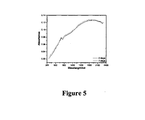
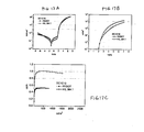
- the films can show excellent stability including substantially no change in the UV-vis-NIR over seven days.
- the UV-vis-NIR spectra can also be sensitive to pH which provides for applications.
- a device comprising a layer comprising the composition comprising: a water soluble or water dispersible regioregular polythiophene comprising (i) at least one organic substituent, and (ii) at least one sulfonate substituent comprising sulfonate sulfur bonding directly to the polythiophene backbone.
- the layer is a hole injection layer or a hole transport layer.
- the device can be for example an OLED device, a PLED device, a SMOLED device, or a photovoltaic device.
- the device can comprise at least two electrodes and at least one light emitting or photoactive layer.
- ESD electrostatic dissipation
- said ESD material comprising at least one water soluble or water dispersible polymer comprising regioregular polythiophene comprising: (i) at least one organic substituent; and (ii) at least one sulfonate substituent comprising sulfonate sulfur bonding directly to the polythiophene backbone.
- Another embodiment provides a method of reducing electrostatic charge on a device comprising coating said device with a coating comprising a polythiophene comprising: (i) at least one organic substituent; and (ii) at least one sulfonate substituent comprising sulfonate sulfur bonding directly to the polythiophene backbone.
- the dopant ion is present on the backbone of the polymer and hence migration into other components of the device is eliminated.
- the composition can be totally free or substantially free of separately added small molecule or polymeric dopants.
- the technology helps in altering the energy levels of the polymer by merely varying the sulfonation levels on the polymer backbone.
- donor and acceptor type polymer is provided which has both the donor and acceptor functionality on the same repeat unit.
- the polymer structure is well-defined with alternating donor acceptors. Also important is a method to convert an otherwise water insoluble polymer into water soluble or water dispersible polymer.
- a method is also provided to purify the substance of free sulfuric acid by passing through strong base type anion exchange resin (OH form). Another benefit comes from a method by which the resultant sulfonated polymer is highly water soluble making it easy to clean the reactor. Other advantages include processable polymer, easy to make, and excellent orthogonal compatibility with organic solvents.
- Applications include for example hole injection layer for OLEDs, PLEDs, photovoltaic cells, electrostatic dissipation, supercapacitors, cation transducers, drug release, electrochromics, sensors, FETs, actuators, and membranes.
- substituted groups described above polymers arrived at by describing substituents with further substituents to themselves (e.g., substituted aryl having a substituted aryl group as a substituent which is itself substituted with a substituted aryl group, etc.) are not intended for inclusion herein. In such cases, the maximum number of such substituents is three. That is to say that each of the above descriptions can be constrained by a limitation that, for example, substituted aryl groups are limted to - substituted aryl-(substituted aryl)-substituted aryl.
- impermissible substitution patterns e.g., methyl substituted with 5 fluoro groups or a hydroxyl group alpha to ethenylic or acetylenic unsaturation.
- impermissible substitution patterns are well known to the skilled artisan.
- Electrically conductive polymers are described in The Encyclopedia of Polymer Science and Engineering, Wiley, 1990, pages 298-300 , including polyacetylene, poly(p-phenylene), poly(p-phenylene sulfide), polypyrrole, and polythiophene, which is hereby incorporated by reference in its entirety. This reference also describes blending and copolymerization of polymers, including block copolymer formation.
- Polythiophenes can be homopolymers, copolymers, or block copolymers. Synthetic methods, doping, and polymer characterization, including regioregular polythiophenes with side groups, is provided in, for example, U.S. Patent Nos. 6,602,974 to McCullough et al. and 6,166,172 to McCullough et al. , which are hereby incorporated by reference in their entirety. Additional description can be found in the article, " The Chemistry of Conducting Polythiophenes," by Richard D. McCullough, Adv. Mater. 1998, 10, No. 2, pages 93-116 , and references cited therein, which is hereby incorporated by reference in its entirety.
- Polythiophenes are described, for example, in Roncali, J., Chem. Rev. 1992, 92, 711 ; Schopf et al., Polythiophenes: Electrically Conductive Polymers, Springer: Berlin, 1997 . See also for example US Patent Nos. 4,737,557 and 4,909,959 .
- Block copolymers are described in, for example, Block Copolymers, Overview and Critical Survey, by Noshay and McGrath, Academic Press, 1977 .
- this text describes A-B diblock copolymers (chapter 5), A-B-A triblock copolymers (chapter 6), and - (AB) n - multiblock copolymers (chapter 7), which can form the basis of block copolymer types in the present invention.
- the degree of regioregularity can be, for example, about 90% or more, or about 95% or more, or about 98% or more, or about 99% or more.
- Methods known in the art such as, for example, NMR can be used to measure the degree of regioregularity.
- Regioregularity can arise in multiple ways.
- asymmetric monomers such as a 3-alkylthiophene to provide head-to-tail (HT) poly(3-substituted)thiophene.
- HT head-to-tail
- monomers which have a plane of symmetry between two portions of monomer such as for example a bi-thiophene, providing for example regioregular HH-TT and TT-HH poly(3-substituted thiophenes).
- substituents which can be used to solubilize conducting polymers with side chains include alkoxy and alkyl including for example C1 to C25 groups, as well as heteroatom systems which include for example oxygen and nitrogen.
- substituents having at least three carbon atoms, or at least five carbon atoms can be used.
- Mixed substituents can be used.
- the substituents can be nonpolar, polar or functional organic substitutents.
- the side group can be called a substituent R which can be for example alkyl, perhaloalkyl, vinyl, acetylenic, alkoxy, aryloxy, vinyloxy, thioalkyl, thioaryl, ketyl, thioketyl, and optionally can be substituted with atoms other than hydrogen.
- R can be for example alkyl, perhaloalkyl, vinyl, acetylenic, alkoxy, aryloxy, vinyloxy, thioalkyl, thioaryl, ketyl, thioketyl, and optionally can be substituted with atoms other than hydrogen.
- Thiophene polymers can be star shaped polymers with the number of branches being for example more than three and comprising thiophene units.
- Thiophene polymers can be dendrimers. See for example Anthopoulos et al., Applied Physics Letters, 82, 26, June 30, 2003, 4824-4826 , and further description of dendrimers hereinafter.
- Heterocyclic polymers are particularly preferred.
- a particularly preferred system is the polythiophene system and the regioregular polythiophene system.
- Polymers can be obtained from Plextronics, Inc., Pittsburgh, PA including for example polythiophene-based polymers such as for example Plexcore, Plexcoat, and similar materials.
- Another embodiment includes heterocyclic conjugated polymers which are relatively regioirregular.
- the degree of regioregularity can be about 90% or less, or about 80% or less, or about 70% or less, or about 60% or less, or about 50% or less.
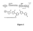
- Figure 1 illustrates a general sulfonation scheme for different conducting polymers and heterocyclic types of conducting polymers, including those which have a heterocyclic atom such as S, N, Se, Te, and Si.
- R is not particularly limited but can be for example a group which provides a solubilizing function such as alkyl or alkoxy.
- Figure 2 illustrates a polythiophene system.
- a composition comprising: a water soluble or water dispersible regioregular polythiophene comprising (i) at least one organic substituent, and (ii) at least one sulfonated substituent comprising sulfur bonding directly to the polythiophene backbone.
- the polymer composition can be yet called regioregular for present purposes.
- Sulfonation is generally known in the art, wherein there is an introduction into an organic molecule of the sulfonic acid group or its salts, -SO 3 H, wherein the sulfur atom is bonded to carbon of the organic molecule.
- Examples in the patent literature include for example US Patent No. 5,548,060 to Allcock et al. ; 6,365,294 to Pintauro et al. ; 5,137,991 to Epstein et al. ; and 5,993,694 to Ito et al. Additional sulfonation methods are described in for example (1) Sotzing, G. A.
- the sulfonated substituent can be in various forms.
- the sulfonated substituent can be in acid form; or the sulfonated substituent can be in salt form comprising a counterion; or the sulfonated substituent can be in salt form comprising a counterion, wherein the counterion comprises organic groups; or the sulfonated substituent can be in salt form comprising a counterion, wherein the counterion comprises an organic cation including for example alkyl groups and is free of metal; or the sulfonated substituent is in salt form comprising a counterion, wherein the counterion comprises a metal cation.
- Sulfonation of polymers can be carried out by methods known in the art using sulfonation reagents. In many cases, it is desirable to reduce the amounts of sulfonating agent needed and the amount of solvent needed. In many cases, it is desirable to reduce the amount of work-up needed including the amount of work-up solvent such as water to remove for example excess acid.
- Sulfonation is represented in Figures 1 and 2 for conducting polymers generally and for polythiophenes in particular. Solid polymer can be added to sulfonation reagent in film or powder form. Specialized processes can be used as needed such as micro-fluidizer or ultrafiltration including use of ultrafiltration membrane filters and use of continuous processes.
- polythiophene can be treated with fuming sulfuric acid at temperatures of for example about 0 to about 100 degrees celsius, or about 22 to about 100 degrees celsius, or about 50 to about 100 degrees celsius, or about 80-85 degrees celsius.
- the degree of sulfonation can be controlled to for example about 5% to about 95%, or about 10% to about 90%, or to about 25% to about 75%. As sulfonation progresses, the sulfonated polythiophene is solublized and/or dispersed in the strong acid.
- the polymers can be treated with ion exchange resins or treated by ultrafiltration.
- the sulfonated polymer can be modified as illustrated in for example Figure 3 .
- a variety of bases can be used; exchange of a variety of counterions can be used. This can result in for example (i) neutralizing acid, and/or (ii) tuning the energy levels and altering of hole injection ability.
- Figure 3 illustrates for example metal ion, ammonium ion (including alky and aryl substituted), phophonium ion (also alkyl or aryl substituted), imidazolinium, thiazolinium, and oxazolinium.
- Modification can also provide better solubility including for example better solubility in organic solvents such as for example aprotic solvents such as N,N-dimethylformamide (DMF), N,N-dimethyl acetamide (DMAc), N-methyl pyrrolidinone (NMP), dimethylsulfoxide (DMSO), and the like.
- aprotic solvents such as N,N-dimethylformamide (DMF), N,N-dimethyl acetamide (DMAc), N-methyl pyrrolidinone (NMP), dimethylsulfoxide (DMSO), and the like.
- Another example of modification is conversion of sulfonic acid to an alkyl/aryl sulfonate ester which could be further substituted.
- Polymers can be dedoped by addition of a variety of forms of appropriate base in appropriate quantities. In some cases, this can be observed from blue shifting of the absorption of the conjugated polymer.
- the type of polymer to be sulfonated can be varied as illustrated in for example Figure 4 for a bis-thiophene monomer.
- Dimers can be used in making polymers. Symmetrical dimers can be used. Examples include those which are HH or TT (head to head, tail to tail, respectively) coupled but have at least one position open for sulfonation.
- the polymer provides one position for sulfonation.
- the polymer microstructure and regioregularity can provide polymers wherein alternating donors and acceptors can be made.
- Sulfonation can be performed on the neutral conjugated polymer.
- Absorption spectra can be used to confirm that the polymer is self-doped. For example, absorption can extend into the near IR.
- the polymers can be very stable in the self-doped state as illustrated in Figure 5 .
- the properties of the polymer can be controlled by pH and acid content as illustrated in Figure 6 for pH. Raising pH is a particularly important formulation strategy. Titration and neutralization can be carried out.
- acid content include at least 10 mg NaOH/g solids, or at least 50 mg NaOH/g solids, at least 100 mg NaOH/g solids, or at least 200 mg NaOH/g solids including for example 10 mg NaOH/g solids to about 250 mg NaOH/g solids.
- pH values can be for example 1.8 to 3.0, or 1.9 to 5, or 2.0 to 7.0. In many cases, it is desirable to be less acidic than the PEDOT/PSS material. pH can vary with the percentage of solids.
- the direct bonding of the sulfonate sulfur atom to the polythiophene can provide tunability of band gap structure.
- the polythiophene is a regio regular polythiophene having a degree of regioregularity of at least about 90%; the polythiophene is a regio regular polythiophene having a degree of regioregularity of at least about 98%; the polythiophene is water soluble; the polythiophene is doped; the organic substitutent comprises at least one heteroatom; the organic substitutent is an alkoxy or alkyl substituent; the polythiophene is an alternating copolymer; the polythiophene is prepared from a bithiophene monomer; wherein the polythiophene is a homopolymer of a thiophene, a copolymer comprising thiophene units, or a block copolymer comprising at least one block of polythiophene; the polythiophene is characterized by a degree of sulfonation of about 10% to about 90%; the polythioph
- the polymer can be converted to film form by methods known in the art for characterization of for example UV-Vis-NIR properties and electrochemistry for the tuning of energy levels including HOMO and LUMO. Stability can be examined.
- sulfonation may also result in substitutent or side groups also comprising sulfonate groups.
- substitutent or side groups also comprising sulfonate groups.
- an aromatic or phenyl group in the substituent could be sulfonated.
- an embodiment for the polymer which can be subjected to sulfonation to produce sulfonated substituents on the polymer backbone can be represented by formula (I), wherein R can be optionally substituted alkyl, optionally substituted alkoxy, and optionally substituted aryloxy.
- substituents for the optional substitution include hydroxyl, phenyl, and additional optionally substituted alkoxy groups.
- the alkoxy groups can be in turn optionally substituted with hydroxyl, phenyl, or alkoxy groups; or wherein R can be an optionally substituted alkylene oxide.
- Substituents can be for example hydroxyl, phenyl, or alkoxy groups; or wherein R can be optionally substituted ethylene oxide or optionally substituted propylene oxide or other lower alkyleneoxy units.
- Substituents can be for example hydroxyl, phenyl, or alkoxy groups; or R can be an optionally substituted alkylene such as for example methylene or ethylene, with substituents being for example optionally substituted alkyleneoxy such as ethyleneoxy or propyleneoxy; substituents can be for example hydroxyl, phenyl, or alkoxy.
- the substitutent group R in (I) can be linked to the thiophene by an oxygen atom as alkoxy or phenoxy, wherein the substituent can be characterized by the corresponding alcohol or phenol, respectively.
- the alcohol for example, can be linear or branched, and can have C2 - C20, or C4 - C 18, or C6 to C 14 carbon atoms.
- the alcohol can be for example an alkyl alcohol, or an ethylene glycol, or a propylene glycol, or a diethylene glycol, or a dipropylene glycol, or a tripropylene glycol.
- Additional examples can be monoethylene glycol ethers and acetates, diethylene glycol ethers and acetates, triethylene glycol ethers and acetates, and the like.
- alcohols which can be linked to the thiophene ring through the oxygen atom include hexyl cellosolve, Dowanol PnB, ethyl carbitol, Dowanol DPnB, phenyl carbitol, butyl cellosolve, butyl carbitol, Dowanol DPM, diisobutyl carbinol, 2-ethylhexyl alcohol, methyl isobutyl carbinol, Dowanol Eph, Dowanol PnP, Dowanol PPh, propyl carbitol, hexyl carbitol, 2-ethylhexyl carbitol, Dowanol DPnP, Dowanol TPM, methyl carbitol, Dowano
- the structure shown in (I) can stand alone as a polymer or it can be part of a block copolymer with another segment.
- the n value for the polymers Ia, Ib, Ic, and Id can reflect molecular weights known in the art and in references cited herein such as for example, 25 - 5,000, or 50 - 1,000;
- the p value for Ia-Id can be for example 0, 1, or 2.
- the m value can be for example 0, 1, 2, 3, or 4, or even higher such as for example 6, 11, or 16 (e.g., as found in Carbowax PEG 350, 550, 750).
- Y can be for example hydrogen, C1-C8 alkyl, optionally substituted C1-C6 alkenyl, and aryl.
- Y can be for example hydrogen, optionally substituted vinyl, optionally substituted allyl, methyl, ethyl, propyl, butyl, hexyl, octyl, or phenyl.
- Y can be for example hydrogen, methyl, ethyl, prop-1-yl, hex-1-yl, hex-2-yl, hex-3-yl, oct-1-yl, oct-2-yl, oct-3-yl, oct-4-yl.
- R1 and R2 independently can be selected from hydrogen and methyl, provided that only one of R1 and R2 is methyl.
- R1 and R2 can be each hydrogen.
- R1 can be methyl and R2 can be hydrogen.
- R1 can be hydrogen and R2 can be methyl.
- one embodiment provides a method for making a composition according to claim 1 comprising: reacting a soluble regioregular polythiophene comprising at least one organic substituent with a sulfonation reagent so that the polythiophene comprises at least one sulfonated substituent comprising sulfur bonding directly to the polythiophene backbone.
- the sulfonation reagent is sulfuric acid; the sulfonation reagent is a sulfate compound; the reacted polythiophene is doped; the reacting results in a degree of sulfonation of at least 10%; the reacting results in a degree of sulfonation of at least 50%; the reacting results in a degree of sulfonation of at least 75%; the sulfonation reagent is sulfuric acid, and the reacting results in a degree of sulfonation of at least 75%; the sulfonation reagent is sulfuric acid, and the reacting results in a degree of sulfonation of at least 75%; and wherein the polythiophene is a regio regular polythiophene having a degree of regioregularity of at least about 90%; and the reacting results in a degree of sulfonation of at least 50%, and wherein the polythiophene is
- the degree of sulfonation can be for example about 10% to about 100%, or about 30% to about 90%, or about 50% to 90%.
- the acid value or acid number can be adapted for an application but can be for example about 250 mg KOH/g polymer, or about 50 to about 250 mg KOH/g polymer, or about 75 to about 200 mg KOH/g polymer, or about 100 to about 150 mg KOH/g polymer. This can be less than competitive polymers such as for example CH8000 which has 651 mg KOH/g solid.
- a solution formulated for, for example, an HIL application can have an acid value of for example about 0.1 to about 0.8 mg KOH/g HIL solution, or about 0.2 mg to about 0.6 mg KOH/g HIL solution.
- the pH of the formulation can be for example greater than about 2, or about 2.0 to about 3.0, or about 2.3 to about 2.7. This can be less acidic than a variety of competitive materials such as for example Baytron AI4083 which exhibits a pH of about 1.7 and CH8000 which exhibits a pH of about 1.3.
- the conducting polymer and polythiophene compositions, sulfonated as described above, can be formulated and blended by methods known in the art to formulators including, for example, varying the amounts of the components, varying combinations of different structural types, use of different mixing conditions, using different solvents, applying different film preparation conditions, using different purification methods, and the like. Formulations for specific applications in hole injection technology are particularly important.
- the blend can be compatible when it is not characterized by excessive phase separation and forms functionally useful, mechanically stable films which can function as a hole injection layer.
- Compatible blends are known in the art. See, for example, US Patent Nos. 4,387,187 ; 4,415,706 ; 4,485,031 ; 4,898,912 ; 4,929,388 ; 4,935,164 ; and 4,990,557 .
- Compatible blends do not have to be miscible blends, but are sufficiently mixed and stable to provide useful function, particularly in thin film form such as, for example, about 2 nm to about 100 nm.
- Blending methods may include solution blending of a predissolved conducting polymer either in neutral or oxidized form disintegrated into nanosized particles (typically from tens to hundreds of nanometers) with conventional polymers (e.g., polystyrene (PS), poly(methyl methacrylate) (PMMA), poly(vinyl acetate) (PVA)) by sonicating, agitation, or shear.
- PS polystyrene
- PMMA poly(methyl methacrylate)
- PVA poly(vinyl acetate)
- Such blends provide fine dispersion of film-forming submicronic particles of stable polymer matrix solutions. Films can be prepared and analyzed for compatibility by spin coating.
- a matrix component can be used which helps provide the needed properties, such as planarization, for the hole injection or hole transport layers.
- the matrix component including planarizing agents, when blended with the hole injection component, will facilitate the formation of the HIL or HTL layer in a device such as an OLED or PV device. It will also be soluble in the solvent that is used to apply the HIL system.
- the planarizing agent may be comprised of, for example, a polymer or oligomer such as an organic polymer such as poly(styrene) or poly(styrene) derivatives, poly(vinyl acetate) or its derivatives, poly(ethylene glycol) or its derivatives, poly(ethylene-co-vinyl acetate), poly(pyrrolidone) or its derivatives (e.g., poly(1-vinylpyrrolidone-co-vinyl acetate)), poly(vinyl pyridine) or its derivatives, poly(methyl methacrylate) or its derivatives, poly(butyl acrylate) or its derivatives.
- a polymer or oligomer such as an organic polymer such as poly(styrene) or poly(styrene) derivatives, poly(vinyl acetate) or its derivatives, poly(ethylene glycol) or its derivatives, poly(ethylene-co-vinyl acetate), poly(pyrrolidon
- More than one non-conductive polymer can be used in the formulation.
- planarizing agent and the hole injection component could be represented by a copolymer that contains an ICP segment and a non-conjugated segment with a composition like similar to that described herein.
- the planarizing agent can also be a "non-fugitive", small molecule that is soluble in the application solvent, but does not evaporate upon removal of the solvent. It may possess alkyl, aryl, or functional alkyl or aryl character.
- the matrix component or planarization agent can also provide other useful functions such as resistivity control and transparency control. Planarity can be determined by methods known in the art including AFM measurements.
- the solvent system can be a mixture of water and organic solvent, including water miscible solvents, and solvents that comprise oxygen, carbon, and hydrogen, such as for example an alcohol or an etheric alcohol.
- water miscible solvents include alcohols such as isopropanol, ethanol, and methanol, and ethylene glycols and propylene glycols from Dow Chemical and Eastman Chemical. See for example Cellosolve, Carbitol, propane diol, methyl carbitol, butyl cellosolve, Dowanol PM,
- the amount of water can be greater than the amount of organic solvent.
- a wide variety of combination of solvents can be used including non-aqueous including alcohols and other polar solvents.
- the composition can comprise a first solvent and a second solvent, different than the first solvent.
- water soluble resins and aqueous dispersions can be used.
- Aqueous dispersions can be for example poly(styrene sulfonic acid) (i.e. PSS dispersion), Nafion dispersion (e.g., sulfonated fluorinated polymers), latex, and polyurethane dispersions.
- PSS dispersion poly(styrene sulfonic acid)
- Nafion dispersion e.g., sulfonated fluorinated polymers
- latex e.g., polyurethane dispersions
- water soluble polymers include polyvinylpyrollidinone and polyvinylalcohol.
- resins include cellulose acetate resins (CA, CAB, CAP - Eastman).
- Formulation can be carried out to modify surface energy, conductivity, film formation, solubility, crosslinking, morphology, film quality, specific application (e.g, spin coat, ink jet printing, screen printing, and the like).
- Surfactants can be used including for example ionic and non-ionic surfactants, as well as polymer surfactants, fluorinated surfactants, and ionomers.
- Resins and HIL inks can be dispersed and/or dissolved by any method known in the art including for example sonication.
- the formulation can be formulated to include crosslinking agents which provide crosslinked structures which may swell but not dissolve upon crosslinking.
- Preferred embodiments include for example a coating composition comprising: (A) water, (B) a water soluble or water-dispersible regioregular polythiophene comprising (i) at least one organic substituent, and (ii) at least one sulfonated substituent comprising sulfur bonding directly to the polythiophene backbone, and (C) a synthetic polymer different from (B); optionally further comprising an organic co-solvent; or further comprising an organic co-solvent, wherein the weight amount of water is greater than the weight amount of the organic co-solvent; or further comprising a second synthetic polymer different from (B) and (C); wherein the synthetic polymer is a water-soluble polymer; or wherein the synthetic polymer has a carbon backbone with a polar functional group in the side group; or wherein the amount of the synthetic polymer (C) is at least three times the amount of the regioregular polythiophene (B); wherein the amount of the synthetic polymer (C) is
- materials and polymers that can be added to the formulation include, for example, poly(vinyl alcohol), including poly(vinyl alcohol) which is 88% hydrolyzed, poly(2-acrylamido-2-methyl-1-propane sulfonic acid), poly(2-acrylamido-2-methyl-1-propane sulfonic acid-co-styrene), poly(1-vinyl pyrolidone-co-vinyl acetate), poly(acrylamide-co-acrylic acid), polyurethane dispersion, acrylic latex dispersion, poly(styrene-ran-ethylene)sulfonated solution, poly(4-vinyl phenol)-co-PMMA, poly(vinyl acetate-co-butyl maleate-co-isobornyl acrylate), poly-4-vinylpyridine, and combinations thereof. In some cases, the poly-4-vinylpyridine may not provide as good results as other materials.
- the sulfonated polymer is dissolved or dispersed in water, or a mixture of water and a water soluble organic solvent, or an organic solvent.
- additional ingredients can be mixed in including for example a second type of polymer.
- compositions can comprise a first solvent and a second solvent.
- the first solvent can be water and the second solvent can be an organic solvent miscible with water.
- These two solvents can be mixed in a wide variety of ratios adapted for a particular application.
- the relative amount (by weight or volume) of the first solvent to second solvent can range from for example 100 parts first solvent and 0 parts second solvent, to 0 parts first solvent and 100 parts second solvent, or 90 parts first solvent and 10 parts second solvent, to 10 parts first solvent and 90 parts second solvent, 80 parts first solvent and 20 parts second solvent, to 20 parts first solvent and 80 parts second solvent, 30 parts first solvent and 70 parts second solvent, to 70 parts first solvent and 30 parts second solvent, 60 parts first solvent and 40 parts second solvent, to 40 parts first solvent and 60 parts second solvent.
- the amount of sulfonated polymer is at least about 4 wt.% with respect to the solid content
- the sulfonated polymer can be present with respect to total solid content at about 1 wt. % to about 10 wt.%, or about 4 wt.% to about 8 wt.%.
- a coated substrate comprising: a solid surface, a coating disposed on the surface, wherein the coating comprises a composition comprising: a water soluble, water dispersible, or water swellable regioregular polythiophene comprising (i) at least one organic substituent, and (ii) at least one sulfonated substituent comprising sulfur bonding directly to the polythiophene backbone.
- the solid surface can be for example an electrode including a transparent electrode such as indium tin oxide.
- the surface can be a light emitting polymer layer or a hole transport layer.
- the thickness of the coating can be for example 5 nm to 5 microns, 10 nm to 1 micron, 25 nm to 500 nm, or 50 nm to 250 nm. Residual solvent may be present.
- the coating may be crosslinked or patterned.
- a coated substrate comprising: (A) a solid surface having a coating disposed thereon comprising (B) a water soluble or water-dispersible regioregular polythiophene comprising (i) at least one organic substituent, and (ii) at least one sulfonated substituent comprising sulfur bonding directly to the polythiophene backbone, and (C) a synthetic polymer different from (B).
- a solid surface can be for example an electrode including a transparent electrode such as indium tin oxide.
- the surface can be a light emitting polymer layer or a hole transport layer.
- the thickness of the coating can be for example 5 nm to 5 microns, 10 nm to 1 micron, 25 nm to 500 nm, or 50 nm to 250 nm. Residual solvent may be present.
- the coating may be crosslinked or patterned.
- Microscale or nanoscale patterning can be carried out to form nanostructure or microstructures on the surface.
- Printing processes can include for example flexography, letter press, soft lithography, gravure, pad, offset lithography, screen, and inkjet printing.
- the surface can be the surface of a homogeneous, heterogeneous, or multilayer substrate.
- Substrates can be those used in printed electronics. Substrates can be for example plastic, glass, metals, including silver and gold.
- the HIL system is preferred and can be applied by spin casting, drop casting, dip-coating, spray-coating, or by printing methods such as ink jet printing, off-set printing, or by a transfer process.
- ink jet printing is described in US Patent No. 6,682,175 to Otsuka and in Hebner et al. , Applied Physics Letters, 72, no. 5, February 2, 1998, pages 519-521 .
- an HIL as a film of an HIL system can be provided that is about 10 nm to about 50 ⁇ m in thickness with typical thickness ranging from about 50 nm to about 1 ⁇ m. In another embodiment, thickness can be about 10 ⁇ m to about 500 nm, and more particularly, about 10 nm to about 100 nm.
- HILs and HTLs for Hole Injection Layers, and Hole Transport Layers, respectively.
- applications include hole injection layer for OLEDs, PLEDs, photovoltaic cells, supercapacitors, cation transducers, drug release, electrochromics, sensors, FETs, actuators, and membranes.
- Another application is as an electrode modifier including an electrode modifier for an organic field effect transistor (OFETS).
- OFETS organic field effect transistor
- Other applications include those in the field of printed electronics, printed electronics devices, and roll-to-roll production processes.
- photovoltaic devices are known in the art as illustrated in for example Figure 7 .
- the devices can comprise, for example, multi-layer structures including for example an anode such as ITO on glass or PET; a hole injection layer; a P/N bulk heterojunction layer; a conditioning layer such as LiF; and a cathode such as for example Ca, Al, or Ba.
- Devices can be adapted to allow for current density versus voltage measurements.
- OLED devices are known in the art as illustrated in for example Figure 9 .
- the devices can comprise, for example, multi-layer structures including for example an anode such as ITO on glass or PET or PEN; a hole injection layer; an electroluminescent layer such as a polymer layer; a conditioning layer such as LiF, and a cathode such as for example Ca, Al, or Ba.
- OLED patents include for example US Patent Nos. 4,356,429 and 4,539,507 (Kodak). Conducting polymers which emit light are described in for example US Patent Nos. 5,247,190 and 5,401,827 (Cambridge Display Technologies). See also Kraft et al., "Electroluminescent Conjugated Polymers - Seeing Polymers in a New Light," Angew. Chem. Int. Ed., 1998, 37, 402-428 , including device architecture, physical principles, solution processing, multilayering, blends, and materials synthesis and formulation, which is hereby incorporated by reference in its entirety.
- Light emitters known in the art and commercially available can be used including various conducting polymers as well as organic molecules, such as materials available from Sumation, Merck Yellow, Merck Blue, American Dye Sources (ADS), Kodak (e.g, AlQ3 and the like), and even Aldrich such as BEHP-PPV.
- organic electroluminescent materials include:
- small organic molecules that emit by fluorescence or by phosphorescence can serve as the organic electroluminescent layer.
- organic electroluminescent materials include: (i) tris(8-hydroxyquinolinato) aluminum (Alq); (ii) 1,3-bis(N,N-dimethylaminophenyl)-1,3,4-oxidazole (OXD-8); (iii) -oxo-bis(2-methyl-8-quinolinato)aluminum; (iv) bis(2-methyl-8-hydroxyquinolinato) aluminum; (v) bis(hydroxybenzoquinolinato) beryllium (BeQ.sub.2); (vi) bis(diphenylvinyl)biphenylene (DPVBI); and (vii) arylamine-substituted distyrylarylene (DSA amine).
- HIL in devices examples include:
- Photoactive layers can be used in OPV devices.
- Photovoltaic devices can be prepared with photoactive layers comprising fullerene derivatives mixed with for example conducting polymers as described in for example US Patent Nos. 5,454,880 (Univ. Cal.); 6,812,399 ; and 6,933,436 .
- Electrode materials and substrates, as well as encapsulating materials can be used.
- OLED parameters can be measured using Methods known in the art. For example, measurements can be carried out at 10 mA/cm 2 .
- Voltage can be for example about 2 to about 8, or about 3 to about 7 including for example about 2 to about 5.
- Brightness can be, for example, at least 250 cd/m 2 , or at least 500 cd/m 2 , or at least 750 cd/m 2 , or at least 1,000 cd/m 2 .
- Efficiency can be, for example, at least 0.25 Cd/A, or at least 0.45 Cd/A, or at least 0.60 Cd/A, or at least 0.70 Cd/A, or at least 1.00 Cd/A, or at least 2.5 Cd/A, or at least 5.00 Cd/A, or at least 7.50 Cd/A, or at least 10.00 Cd/A.
- Lifetime can be measured at 50 mA/cm 2 in hours and can be, for example, at least 50 hours, or at least 100 hours, or at least about 900 hours, or at least 1,000 hours, or at least 1100 hours, or at least 2,000 hours, or at least 5,000 hours.
- brightness can be at least 1,000 cd/m2
- efficiency can be at least 1.00 Cd/A
- lifetime can be at least 1,000 hours, at least 2,500 hours, or at least 5,000 hours.
- J SC values (mA/cm 2 ) can be for example at least 6, or at least 7, or at least 8, or at least 9, or at least 10, or at least 11, or at least 12.
- the values can be for example about 5 to about 12, or about 5 to about 15, or about 5 to about 20.
- V OC values (V) can be for example at least about 0.5, or at least about 0.6, or at least about 0.7, or at least about 0.8, or at least about 0.9, or at least about 1.0, including for example about 0.5 to about 1.0, or about 0.55 to about 0.65.
- FF values can for example at least about 0.2, or at least about 0.3, or at least about 0.4, or at least about 0.5, or at least about 0.6, or at least about 0.7, including also for example about 0.5 to about 0.8, or about 0.5 to about 0.73.
- E (%) values can be for example at least about 1%, or at least about 2%, or at least about 3%, or at least about 4%, or at least about 5%, or at least about 6%, or at least about 7%, including for example about 1% to about 8%, or about 1% to about 7%, or about 1% to about 6%, or about 1% to about 5%, or about 1% to about 3.4%, or about 2% to about 3.4%.
- Sulfonated polymers and formulations thereof as described herein can be made into an ink that can be used to produce high-performance hole-extraction layer for organic photovoltaic devices.
- the efficiency of 3.38% in the working examples was essentially the same as the Baytron AI4083 control device in the same fabrication run.
- HIL layers can conduct holes and mediate hole-extraction as well as current incumbent materials.
- Control materials can be formulated such as PEDOT materials described in US Patent No. 4,959,430 to Jonas et al.
- Baytron materials can be obtained from H.C. Stark.
- Carbazole compounds are described in for example WO 2004/072205 to Brunner et al.
- Degradation rate can be also examined (see for example Figure 16 ). Degradation time until normalized power output is zero for a cell substantially similar to that of Figure 16 and for the conditions described therefore can be for example at least 250 hours, or at least 300 hours, or at least 400 hours, or at least 500 hours.
- sensors and transistors including field effect transistors (e.g., as electrodes or as active channel material, e.g., for use in logic circuits and other electronic circuitry).
- field effect transistors e.g., as electrodes or as active channel material, e.g., for use in logic circuits and other electronic circuitry.
- pH sensors, or sensors which are sensitive to detection of compounds which have functionalities which can bind to acid can be made and used in for example an optical sensing tool.
- Other device applications include for example supercapacitors (e.g., light weight power sources functioning as storage media with good charge capacity), cation transducers (e.g., devices featuring a cation binding event causing an optical or electrical signal), drug release (e.g., drugs with ionic functionalities can be bound to the polymer and a redox chemistry can trigger the release of the drug into the body; or an embedded microchip with the polymer can help trigger the release of the drug into the body by changing the doping profile), electrochromics, actuators (e.g., electrochemical doping/de-doping also can change the volume of the polymer which is the basis for actuating mechanism. Applications based on this can involve artificial muscles activated by electrical pulse, or also smart membranes with tunable pore size for purification of solvents), transparent electrodes to replace for example ITO, and membranes.
- supercapacitors e.g., light weight power sources functioning as storage media with good charge capacity
- cation transducers e.g.,
- Electrostatic dissipation coatings are described in for example US provisional application serial no. 60/760,386 filed January 20, 2006 to Greco et al. (see also PCT application PCT/US2007/001245 filed January 18, 2007 ), which are each hereby incorporated by reference in their entirety including figures, claims, and working examples.
- regioregular polythiophene compositions as described and claimed herein are employed in or as electrostatic dissipation (ESD) coatings, packaging materials, and other forms and applications. Electrostatic discharge is a common problem in many applications including electronic devices which are becoming smaller and more intricate.
- ESD coatings also known as ESD coatings
- Conductive materials can be also blended into other materials such as polymers to form blends and packaging materials.
- the regrioregular polythiophenes or polymers comprising regioregular polythiophenes described herein may be used as the only polymeric component of an ESD coating or be combined (i.e.
- the regioregular polythiophenes can be a homopolymer, a copolymer or a block copolymer.
- a non-limiting example of this embodiment involves a device comprising an electrostatic dissipation (ESD) coating, said ESD coating comprising at least one water soluble or water dispersible polymer comprising regioregular polythiophene comprising: at least one organic substituent; and at least one sulfonated substituent comprising sulfur bonding directly to the polythiophene backbone.
- ESD electrostatic dissipation
- the coating may be a blend of one or more polymers wherein at least one comprises regioregular polythiophene.
- the ESD coating can comprise at least one polymer without regioregular polythiophene. In these ESD coatings, where a polymeric blend is used, the polymers are preferably compatible.
- the molecular weight of the polymers in the coating can vary.
- the number average molecular weight of the polymer comprising regioregular polythiophene, the polymer without regioregular polythiophene, or both can be between about 5,000 and about 50,000.
- the number average molecular weight of the polymer without regioregular polythiophene can be for example about 5,000 to about 10,000,000, or about 5,000 to about 1,000,000.
- At least one polymer may be cross-linked for various reasons such as improved chemical, mechanical or electrical properties.
- Regioregularity of the polythiophene may be, for example, at least about 85%, or at least about 95%, or at least about 98%.
- the degree of regioregularity can be at least about 70%, or at least about 80%.
- cost may be important and the highest levels of regioregularity may not be needed to achieve the performance.
- the ESD coating also preferably contains less that about 50 wt.%, or less than about 30 wt. % regioregular polythiophene polymer.
- the minimum amount of the polymer can be for example about 0.1 wt.% or about 1 wt.% or about 10 wt.%.
- the polymer which does not comprise regioregular polythiophene can be a synthetic polymer and is not particularly limited. It can be for example thermoplastic. It can be a water soluble polymer or a polymer capable of aqueous based dispersion.
- Examples include organic polymers, synthetic polymers polymer or oligomer such as a polyvinyl polymer having a polymer side group, a poly(styrene) or a poly(styrene) derivative, poly(vinyl acetate) or its derivatives, poly(ethylene glycol) or its derivatives such as poly(ethylene-co-vinyl acetate), poly(pyrrolidone) or its derivatives such as poly(1-vinylpyrrolidone-co-vinyl acetate, poly(vinyl pyridine) or its derivatives, poly(methyl methacrylate) or its derivatives, poly(butyl acrylate) or its derivatives.
- synthetic polymers polymer or oligomer such as a polyvinyl polymer having a polymer side group, a poly(styrene) or a poly(styrene) derivative, poly(vinyl acetate) or its derivatives, poly(ethylene glycol) or its derivatives such as poly(
- Preferred examples include poly(styrene) and poly(4-vinyl pyridine).
- Another example is a water-soluble or water-dispersable polyurethane.
- the conductivity of the coating can be tuned. For example, the amount of conductive material can be increased or decreased.
- doping can be used although the self-doping nature of the sulfonated polymer provides doping. Further doping may be achieved via organic, inorganic or ambient species and in forms of solids, liquids, gases, or a combination thereof. Oxidation is a useful method of enhancing electrical conductivity of polythiophenes. Useful halogen dopants include Br, I, Cl.
- Inorganic dopants include compounds that may be represented by iron trichloride, gold trichloride, arsenic pentafluoride, alkali metal salts of hypochlorite, protic acids such as benzenesulfonic acid and derivatives thereof, propionic acid, organic carboxylic and sulfonic acids, nitrosonium salts, NOPF 6 or NOBF 4 , organic oxidants, tetracyanoquinone, dichlorodicyanoquinone, hypervalent iodine oxidants, iodosylbenzene, iodobenzene diacetate or a combination thereof.
- Including certain polymers in the blend can also lead to a doping effect in the polythiophenes.
- a polymer comprising an oxidative functionality, acidic functionality, poly(styrene sulfonic) acid or a combination thereof can be also included in the coating.
- Other compounds that provide a doping effect include: certain Lewis acids, iron trichloride, gold trichloride, and arsenic pentafluoride, protic organic acids, inorganic acids, benzenesulfonic acids and derivatives thereof, propionic acid, organic carboxylic acids, sulfonic acids, mineral acids, nitric acids , sulfuric acids, hydrochloric acids, tetracyanoquinone, dichlorodicyanoquinone, hypervalent iodine, iodosylbenzene, iodobenzene diacetate.
- Ambient doping typically occurs via species in the ambient air such as oxygen, carbon dioxide and moisture.
- the polymer comprising regioregular polythiophene is preferably doped sufficiently to provide an electronic conductivity in the material of at least about 10 -10 siemens/cm (S/cm) or between about 10 -13 siemens/cm to about 10 -3 siemens/cm.
- the ESD coating preferably should retain efficacy over the lifetime of the device. Roughly, in certain cases it is desirable that the coating retain electronic conductivity of at least 10 -13 for at least 1000 hrs.
- the regioregular polythiophene is doped with a quinone compound and the coating has a thickness of about 10 nm to about 100 nm, and wherein the polymer which does not comprise regioregular polythiophene comprises a polystyrene, a polystyrene derivative, a polyurethane, a polyacrylate, a polypyridine, or a polyvinyl phenol.
- ESD coating can be achieved via spin coating, ink jetting, roll coating, gravure printing, dip coating, zone casting, or a combination thereof. Normally the applied coating is greater than 10 nm in thickness. Often, the coating is applied to insulating surfaces such as glass, silica, polymer or any others where static charge builds up. Additionally, the conductive polymer can be blended into materials used to fabricate packaging film used for protection of for example sensitive electronic equipment. This may be achieved by typical processing methodologies such as for example blown film extrusion. Optical properties of the finished coating can vary tremendously depending on the type of blend and percent ratio of the polythiophene polymers. Preferably, transparency of the coating is at least 90% over the wavelength region of 300 nm to 800 nm.
- the ESD coatings can be applied to a wide variety of devices requiring static charge dissipation.
- Non-limiting examples include: semiconductor devices and components, integrated circuits, display screens, projectors, aircraft wide screens, vehicular wide screens or CRT screens.
- an ESD coating is formulated from an aqueous solution of sulfonated conducting polymer.
- the pH can be adjusted to about neutral with a basic compound such as an amine.
- Water as well as an aqueous solution of a second polymer can be added.
- a non-aqueous solvent can be used to improve dispersion. See working example below.
- the weight percentage of conducting polymer such as sulfonated polythiophene in the final solids can be for example about 2 wt.% to about 30 wt.%, or about 5 wt.% to about 20 wt.%.
- Water content in the solution before removal of solvent can be for example about 40 wt.% to about 80 wt.% in solution.
- the sulfonated polymers described herein can be used in transparent electrode applications.
- the wet polymer was diluted with de-ionized water to make the total solids content between 0.5 and 1 % and sonicated for 30 min.
- the suspension was then passed in 2 lots through a glass column (1" diameter) packed with 30 g of fresh Amberjet 4400 (OH form, Aldrich) ion-exchange resin, for each lot. This process removed any residual free sulfuric acid.
- the aqueous suspension of the sulfonated polymer thus obtained did not show any aggregation or precipitation even after several days of storage under ambient conditions at these concentrations.
- the acid equivalent was determined to be 74.4 mg NaOH per gram of sulfonated polymer.
- Elemental analysis (CHS) of the polymer was done at Galbraith Laboratories Inc. and the CHS content was determined to be 43.22, 3.37 and 23.44 % by weight, respectively. Based on the C/S ratio, the sulfonation level was determined to be 83 %.
- Sulfonated poly(3-(ethyloxyethoxyethoxyethoxy)thiophene-2,5-diyl) was prepared using a similar procedure as shown in example 2.
- UV-Vis-NIR spectra resembles that of for the polymer of Example 1 characterized by a strong absorbance throughout the NIR region indicative of a bipolaronic character.
- sulfonation can also be carried out by dissolving poly(3-(methyloxyethoxyethoxy)thiophene-2,5-diyl) in chloroform and adding acetyl sulfate reagent prepared in situ in anhydrous 1,2-dichloroethane as reported by Makoski H.S. and Lundberg, R. US Patent 3,870,841, 1975 .
- 1.0 gm poly(3-(methyloxyethoxyethoxy)thiophene-2,5-diyl) was heated to reflux with 50 mL chloroform.
- acetyl sulfate (1 eq) reagent was added.
- the reaction mixture was refluxed for 27 h and added to 200 mL methanol, followed by filtering, washing with de-ionized water to neutral pH and finally with methanol before drying to a fine powder.
- Tetra-n-butylammonium salt of P3MEET-S was prepared by adding 42.3 mg of n-Bu 4 NOH.30H 2 O to 5.027 g of 0.6% aqueous P3MEET-S. This represents 0.95 eq of free acid based on previous titration results, see Example 1. pH of the solution was measured to be 4.30 after adding the n -Bu 4 NOH.30H z O (called T1). pH of as prepared P3MEET-S was 3.165. Similarly, another solution with 88.8 mg n -Bu 4 NOH.3OH 2 O was added to 5.002 g of 0.6% aqueous P3MEET-S. pH of this solution was measured to be 11.2 (called T2).
- the solids ( ⁇ 2 gms) were added to 100 mL chloroform followed by 15 mL of aqueous solution of hydrazine (35 wt %). Reflux was carried out for 30 min. Addition of hydrazine caused the polymer to dissolve in chloroform. The solution was poured into 1 L methanol + 100 mL water, and stirred for an hour and filtered. The filtered solids were stirred in 150 mL water at 50°C for 1 h and filtered. The solids were added to 180 mL water plus 10 mL Conc. HCl and heated for 1 h at 50°C, filtered and dried in oven at RT for 2 days.
- Figure 5 shows the Vis-NIR spectrum of a doped film of the sulfonated poly(3-(methoxyethoxyethoxy)thiophene-2,5-diyl) spin-coated onto glass plates.
- the films were annealed at 150°C for 15 min after spin coating. These films exhibited very strong absorbance extending into the NIR region, typical of oxidized conjugated polymers.
- the spectrum underwent little/no change even after 7 days of storage under ambient conditions demonstrating the excellent stability in the oxidized form.
- Figure 6 shows spectra of thin films prepared by spinning the above solutions of T1 and T2 onto a glass plate (form working example 4). The films were annealed at 150°C for 10 min before obtaining the spectra.
- Example 7 A solution of Plexcore MPX in water (about 0.61 % by weight) was prepared as described above in Example 1. This solution (4.92g) was added to a vial along with water (4.81g) and placed in an ultrasonic bath for 30 minutes. Poly(4-vinylphenol) (0.27g) was dissolved in 2-butoxyethanol (6.00g) and heated with stirring until the polymer dissolved completely. The two solutions were then combined and mixed thoroughly. The solution was then passed through a 0:22 micron PVDF syringe filter (Millipore).
- Examples 8 and 9 The procedure was similar to that of Example 7 except that an aqueous dispersion of polystyrenesulfonic acid (PSS) was added after the addition of poly(4-vinylphenol).
- PSS polystyrenesulfonic acid
- Example 10 The procedure was similar to that of Example 7 except that PSS was added in place of the poly(4-vinylphenol).
- Example 11 A The procedure is identical to Example 7 except that an aqueous dispersion of NeoRez R-966 (an aliphatic urethane dispersion from Avecia) was added in place of the poly(4-vinylphenol) (PUD is polyurethane dispersion).
- NeoRez R-966 an aliphatic urethane dispersion from Avecia
- Example 11 B The procedure is identical to Example 7 except that Nafion® perfluorinated ion-exchange resin (10% dispersion) was added after the addition of poly(4-vinylphenol). See also Example 11C for use of Nafion ⁇ .
- the device fabrication described below is intended as an illustrative example and does not in any way imply the limitation of the invention to the said fabrication process, device architecture (sequence, number of layers etc.) or materials other than the HIL materials claimed in this invention.
- the OPV devices described herein were fabricated on indium tin oxide (ITO) surfaces deposited on glass substrates.
- ITO indium tin oxide
- the ITO surface was pre-pattemed to define the pixel area of 0.9 cm 2 .
- the device substrates were cleaned by ultrasonication in a dilute soap solution, followed by distilled water for 20 minutes each. This was followed by ultrasonication in isopropanol.
- the substrates were dried under nitrogen flow, following which they were treated in a UV-Ozone chamber operating at 300 W for 20 minutes.
- the cleaned substrates were then coated with the hole collection layer.
- the coating process was done on a spin coater but can be similarly achieved with spray coating, ink-jetting, contact printing or any other deposition method capable of resulting in an HCL film of the desired thickness.
- An HIL ink (from Examples 7, 8, or 9) was spin-coated and then dried at 175 °C for 30 minutes resulting in a 170 nm thick layer.
- the active layer (a 2:1 weight ratio blend of P3HT / PCBM (methanofullerene [6,6]-phenyl C61-butyric acid methyl ester) was applied by spin coating in a nitrogen atmosphere and annealed at 175 °C for 30 minutes resulting in a 200 nm thick layer.
- This film was spun on top of the HIL film with no observable morphological damage to the HIL (independently verified by atomic force microscopy, AFM).
- the substrates were then transferred to a vacuum chamber in which, by means of physical vapor deposition, a cathode layer was deposited.
- the cathode layer was prepared by the sequential deposition of two metal layers, the first being a 5 nm layer of Ca (0.1 nm/sec) followed by a 200 nm layer of A1 (0.5 nm/sec) with the base pressure at 5 x 10 -7 Torr.
- the devices thus obtained were encapsulated with a glass cover slip to prevent exposure to ambient conditions by means of a UV-light curing epoxy resin cured at 80 W/cm 2 UV exposure 4 minutes.
- the OPVs fabricated in this example are representative of the format they may be used in actual applications all of which are considered to be covered by this invention, limited only by the presence of the HIL disclosed herein being present in the device stack.
- the testing example as described below is used only to describe the evaluation of the OPV performance and is not considered to be the only methodology utilized to electrically address the OPV.
- the OPVs comprise pixels on a glass substrate whose electrodes extend outside the encapsulated area of the device which contain the light harvesting portion of the pixels.
- the typical area of each pixel was 0.09 cm 2 .
- the electrodes were contacted with a current source meter such as a Keithley 2400 source meter with a bias applied to the indium tin oxide electrode while the aluminum electrode is earthed.
- the device was then held under the plane wave front of an Oriel 300W Solar simulator equipped with a Xenon lamp at a distance of ⁇ 20 cm from the optics of the Solar simulator.
- the optical power of the light incident on the pixel was 100 mW/cm 2 , while the actual spectrum of the light generated by the Solar simulator approximates the light generated by the Sun, which corresponds to the standard Air Mass 1.5 Global Filter or AM 1.5G spectrum.
- the pixel thus illuminated absorbs light and generates photocurrent.
- This photocurrent comprises positive charges (holes) and negative charges (electrons) which are collected by the electrodes depending on the electrically applied bias.
- This photocurrent was in turn read by the Keithley 2400 source meter.
- the generated photocurrent was measured as a function of the voltage applied to the pixel.
- the short circuit current (the current generated under illumination at zero volts bias) is indicative of the efficiency with which holes are extracted by the hole extraction layer. Besides this, the open circuit voltage and the fill factor together with the short circuit current determine the overall efficiency of the device.
- Figure 7 illustrates a typical conductive polymer photovoltaic cell.
- Figure 8 illustrates representative data.
- the following Table I provides additional data: TABLE I I Jsc (mA/cm2) Voc (V) FF E (%) PEDOT 10.84 0.60 0.55 3.59
- Example 7 9.59 0.59 0.24 1.38
- Example 8 9.72 0.59 0.38 2.14
- Example 9 10.34 0.59 0.55 3.38
- Example 10 6.72 0.59 0.29 1.16
- Figure 16 illustrates degradation of power output of organic photovoltaic cells made with CH8000 and Example 11B as the hole extraction layer.
- the devices are placed under a lamp generating 2 suns of light output and are operating at a temperature of 85°C.
- the OLED devices described herein were fabricated on indium tin oxide (ITO) surfaces deposited on glass substrates.
- ITO indium tin oxide
- the ITO surface was pre-patterned to define the pixel area of 0.9 cm 2 .
- the device substrates were cleaned by ultrasonication in a dilute soap solution followed by distilled water for 20 minutes each. This was followed by ultrasonication in isopropanol.
- the substrates were dried under nitrogen flow, following which they were treated in a UV-Ozone chamber operating at 300 W for 20 minutes.
- the cleaned substrates were then coated with the hole injection layer and dried at 200 °C for 15 minutes (60 nm dry film thickness).
- the coating process was done on a spin coater but can be similarly achieved with spray coating, ink-jetting, contact printing or any other deposition method capable of resulting in an HIL film of the desired thickness. This was followed by the spin coating of the light emitting polymer (LEP) layer which was dried at 170 °C for 15 minutes (75 nm dry film thickness).
- LEP light emitting polymer
- the substrates were then transferred to a vacuum chamber in which, by means of physical vapor deposition, a cathode layer was deposited.
- the cathode layer was prepared by the sequential deposition of two metal layers, the first being a 5 nm layer of Ca (or Ba) (0.1 nm/sec) followed by a 200 nm layer of Al (0.5 nm/sec) with the base pressure at 5 x 10 -7 Torr.
- the devices thus obtained were encapsulated with a glass cover slip to prevent exposure to ambient conditions by means of a UV-light curing epoxy resin cured at 80 W/cm 2 UV exposure for 4 minutes.
- the representative device is an example of hybrid device architecture involving a solution processed hole injection layer (HIL) and a vapor-deposited hole transport layer of N,N'-di(naphthalene-1-yl)-N,N'-diphenyl-benzidine (NPB) and electron transport layer (ETL) and emissive layer of tris(8-hydroxyquinolinato)aluminum (ALQ3) with pre-patterned ITO as anode and LiF and Al as cathode.
- HIL solution processed hole injection layer
- NPB N,N'-di(naphthalene-1-yl)-N,N'-diphenyl-benzidine
- ETL electron transport layer
- AQ3 emissive layer of tris(8-hydroxyquinolinato)aluminum
- the hybrid SMOLED devices described herein were fabricated on indium tin oxide (ITO) surfaces deposited on glass substrates.
- ITO indium tin oxide
- the ITO surface was pre-pattemed to define the pixel area of 0.9 cm 2 .
- the device substrates were cleaned by ultrasonication in a dilute soap solution followed by distilled water for 20 minutes each. This was followed by ultrasonication in isopropanol.
- the substrates were dried under nitrogen flow, after which they were treated under a UV-Ozone chamber operating at 300 W for 20 minutes.
- HIL hole injection layer
- the substrates were then transferred to a vacuum deposition chamber in which by means of physical thermal deposition the organic materials - NPB as hole transport layer and ALQ3 as electron transport and emissive layer - were deposited.
- the thickness of 70 nm was achieved for both NPB and ALQ3 layers respectively.
- deposition of the cathode in the form of a sequential deposition of two metal layers, the first layer being the LiF layer of 0.5 nm thickness followed by a 200 nm layer of Al.
- the following Table summarizes the deposition parameters for the device fabrication:
- the devices thus obtained were encapsulated with a glass cover slip to prevent exposure to ambient conditions by means of a UV-light curing epoxy resin cured at 80 W/cm 2 UV exposure for 4 minutes.
- the OLEDs fabricated in this example are representative of the format they may be used in actual applications all of which are considered to be covered by this invention, limited only by the presence of the HIL disclosed herein being present in the device stack.
- the testing example as described below is used only to describe the evaluation of the OLED performance and is not considered to be the only methodology utilized to electrically address the OLEDs.
- the OLEDs comprise pixels on a glass substrate whose electrodes extend outside the encapsulated area of the device which contain the light emitting portion of the pixels.
- the typical area of each pixel is 0.09 cm 2 .
- the electrodes are contacted with a current source meter such as a Keithley 2400 source meter with a bias applied to the indium tin oxide electrode while the aluminum electrode is earthed.
- a current source meter such as a Keithley 2400 source meter with a bias applied to the indium tin oxide electrode while the aluminum electrode is earthed.
- a current source meter such as a Keithley 2400 source meter
- the HIL assists the injection of charge carriers into the light emitting layer. This results in a low operating voltage of the device (defined as the voltage required to run a given current density through the pixel).
- another Keithley 2400 source meter is used to address a large area silicon photodiode.
- This photodiode is maintained at zero volts bias by the 2400 source meter. It is placed in direct contact with area of the glass substrate directly below the lighted area of the OLED pixel.
- the photodiode collects the light generated by the OLED converting them into photocurrent which is in turn read by the source meter.
- the photodiode current generated is quantified into optical units (candelas / sq. meter) by calibrating it with the help of a Minolta CS-200 Chromameter.
- the Keithley 2400 addressing the OLED pixel applies a voltage sweep to it.
- the resultant current passing through the pixel is measured.
- the current passing through the OLED pixel results in light being generated which then results in a photocurrent reading by the other Keithley 2400 connected to the photodiode.
- the voltage-current-light or IVL data for the pixel is generated. This in turn enables the measurement of other device characteristics such as the lumens per Watt of electrical input power to the pixel and candelas per ampere of pixel current.
- FIG 9 illustrates a schematic representation of an organic light emitting diode (OLED).
- Table II and Figures 10-14 provide device testing data.
- HILs in different example OLED types
- typically performance is quantified by a combination of different parameters such as operating voltage (should be low), brightness in nits (should be bright, luminous efficiency in units of cd/A (reflecting how much electric charge is needed to obtain light from the device) and the lifetime under operation (time required to reach half of the initial luminance value at the start of the test).
- operating voltage should be low
- brightness in nits should be bright
- luminous efficiency in units of cd/A reflecting how much electric charge is needed to obtain light from the device
- lifetime under operation time required to reach half of the initial luminance value at the start of the test.
- Figure 17 illustrates current-voltage luminance performance for OC1C10 based OLED devices comparing PEDOT and HIL 384.1 as described herein. An improvement in efficiency is observed over PEDOT.
- Figure 18 illustrates current-voltage luminance performance for a commercial emitter 1 based OLED devices comparing CH8000 and Example 11C. Comparable performance to CH8000 is obtained for this HIL as evident from the data.
- Figure 19 illustrates luminance decay under passive matrix testing conditions at 70 degrees Celsius for devices comprising a commercial emitter 1. Lifetime for the Example 11C containing device is observed to be better than for CH8000.
- Figure 20 illustrates current-voltage-luminance performance for commercial emitter 2 based OLED devices comparing CH8000 and Example 11C. Comparable performance to CH8000 is obtained for this HIL as evident from the data.
- Figure 21 illustrates luminance decay under passive matrix testing conditions for devices comprising a commercial emitter 2. Lifetime for the HIL 665 device at room temperature is observed to be better than that for PEDOT. Even more dramatic is the lifetime performance at high temperature. While the performance of PEDOT degrades at high temperature that of HIL 665 remains almost equivalent at 85 degrees Celsius compared to room temperature performance.
- Figure 22 illustrates current-voltage-luminance performance for SMOLED devices comparing CH8000 and Example 7. Improved operating voltage is obtained with some loss in efficiency.
- Figure 23 illustrates comparison of luminance degradation for SMOLED devices including CH8000 and Example 7 at an initial luminance of 1,000 nits under DC current at room temperature.
- Table II Measured at 10 mA/cm2 HIL System Emitter Voltage (Volts) Brightness (cd/m2) (Im/W) Efficiency (Cd/A) Baytron CH8000 OC1C10 3.4 59 0.59 Example 7 OC1C10 3.5 38 0.38 Example 8 OC1C10 2.8 34 0.34 Example 9 OC1C10 2.6 20 0.20 Example 10 OC1C10 3.7 66 0.66 Baytron CH8000 Commercial emitter 1 4.2 712 7.1 Example 7 Commercial emitter 1 4.9 799 8.0 Example 8 Commercial emitter 1 4.3 817 8.2 Example 9 Commercial emitter 1 4.6 733 7.3 Example 10 Commercial emitter 1 5.0 822 8.2 Baytron CH8000 Commercial Emitter 2 3.8 1140 11.4 Example 7 Commercial Emitter 2 3.9 47 0.5 Baytron CH8000 Commercial Emitter 2 (with interlayer)
Abstract
Description
- This application claims priority to
U.S. provisional application serial no. 60/832,095 filed on July 21, 2006 U.S. provisional application serial no. 60/845,172 filed on September 18, 2006 - These inventions were made with Government support under Agreement No. DAAD 19-02-3-001 awarded by Army Research Laboratory. The government has certain rights in the inventions.
- Although useful advances are being made in energy saving devices such as organic-based organic light emitting diodes (OLEDs), polymer light emitting diodes (PLEDs), and organic photovoltaic devices (OPVs), further improvements are still needed in providing better processing and performance. For example, one promising type of material is conducting polymers including for example polythiophenes and regioregular polythiophenes, the latter first invented by Richard McCullough. However, problems can arise with doping, purity, and solubility and processing. In particular, it is important to have very good control over the solubility of alternating layers of polymer (e.g., orthogonal or alternating solubility properties among adjacent layers). In particular, hole injection layers and hole transport layers can present difficult problems in view of competing demands and the need for very thin, but high quality, films.
- A need exists for a good platform system to control properties of hole injection and transport layers such as solubility and electronic energy levels like HOMO and LUMO, so that the materials can be adapted for different applications and to function with different materials such as light emitting layers, photoactive layers, and electrodes. In particular, good solubility properties are important, as well as the control of energy levels like HOMO and LUMO and the ability to formulate the system for a particular application and provide the required balance of properties.
- Polythiophenes and regioregular polythiophenes are particularly important. Background references regarding polythiophenes include (1) Sotzing, G. A. Substituted thieno[3,4-b]thiophene polymers, method of making and use thereof, US2005/0124784 A1; (2) Lee, B.; Seshadri, V.; Sotzing, G.A. Ring Sulfonated poly(thieno[3,4-b]thiophene), Adv. Mater. 2005, 17, 1792. (3) Udman, Y. A.; Pekmez, K.; Yildiz, A. Synth. Met. 2004, 142, 7 . (4). Udman, Y. A.; Pekmez, K.; Yildiz, A. Eur. Poly. J. 2004, 40, 1057. (5) "Method for producing soluble conductive polymers having acidic groups "
EP0834885B1 . - Prior art often provides however important limits such as, for example, unstable doping, lack of solubility in starting polymers, lack of versatility in formulation, lack of solvent control, limited fused systems, random sulfonation, lack of copolymerization, lack of control of molecular weight, lack of structural control and regioregularity, lack of interaction between side group and conjugated chain, and also lack of device data.
- Sulfonation and sulfonated polymers can be used to improve performance and processes, particularly with polythiophenes and regioregular polythiophenes. The various embodiments include compositions, methods of making compositions, methods of using compositions, and devices. For example, one embodiment provides a composition comprising: a water soluble or water dispersible regioregular polythiophene comprising (i) at least one organic substituent, and (ii) at least one sulfonate substituent comprising sulfonate sulfur bonding directly to the polythiophene backbone.
- Another embodiment is a composition comprising: a water soluble, water dispersible, or water swellable regioregular polythiophene comprising (i) at least one organic substituent, and (ii) at least one sulfonate substituent comprising sulfonate sulfur bonding directly to the polythiophene backbone. More generally, another embodiment provides a composition comprising: a water soluble or water dispersible regioregular heterocyclic polymer comprising (i) at least one organic substituent, and (ii) at least one sulfonate substituent comprising sulfonate sulfur bonding directly to the polymer backbone. The heterocyclic polymer can be for example a nitrogen-containing or a sulfur-containing heterocyclic polymer.
- Another embodiment comprises a method for making a composition comprising: reacting a soluble regioregular polythiophene comprising (i) at least one organic substituent with a sulfonation reagent so that the polythiophene comprises at least one sulfonate substituent comprising sulfonate sulfur bonding directly to the polythiophene backbone.
- Another embodiment provides a coating composition comprising: (A) water, (B) a water soluble or water dispersible regioregular polythiophene comprising (i) at least one organic substitutent, and (ii) at least one sulfonate substituent comprising sulfonate sulfur bonding directly to the polythiophene backbone, and (C) a synthetic polymer different from (B). The composition can further comprise a water-miscible solvent.
- Still further, also provided is a method of making a coating composition comprising: (A) providing water, (B) providing a water soluble or water-dispersible regioregular polythiophene comprising (i) at least one organic substituent, and (ii) at least one sulfonate substituent comprising sulfonate sulfur bonding directly to the polythiophene backbone, (C) providing a synthetic polymer different from (B), (D) combining in any order (A), (B), and (C) to form a coating composition. The coating composition can also comprise a water-miscible solvent. In further steps, water can be removed to provide a coated surface or substrate.
- Another embodiment is a coated substrate comprising: a solid surface, a coating disposed on the surface, wherein the coating comprises a composition comprising: a water soluble, water dispersible, or water swellable regioregular polythiophene comprising (i) at least one organic substituent, and (ii) at least one sulfonate substituent comprising sulfonate sulfur bonding directly to the polythiophene backbone.
- Still further, another embodiment is a coated substrate comprising: (B) a water soluble, water-dispersible, or water swellable regioregular polythiophene comprising (i) at least one organic substituent, and (ii) at least one sulfonate substituent comprising sulfonate sulfur bonding directly to the polythiophene backbone, (C) a synthetic polymer different from (B).
- The films can show excellent stability including substantially no change in the UV-vis-NIR over seven days. The UV-vis-NIR spectra can also be sensitive to pH which provides for applications.
- Also provided are devices. For example, herein is provided a device comprising a layer comprising the composition comprising: a water soluble or water dispersible regioregular polythiophene comprising (i) at least one organic substituent, and (ii) at least one sulfonate substituent comprising sulfonate sulfur bonding directly to the polythiophene backbone. In one embodiment, the layer is a hole injection layer or a hole transport layer. The device can be for example an OLED device, a PLED device, a SMOLED device, or a photovoltaic device. The device can comprise at least two electrodes and at least one light emitting or photoactive layer.
- Another embodiment is a device comprising an electrostatic dissipation (ESD) material, said ESD material comprising at least one water soluble or water dispersible polymer comprising regioregular polythiophene comprising: (i) at least one organic substituent; and (ii) at least one sulfonate substituent comprising sulfonate sulfur bonding directly to the polythiophene backbone.
- Another embodiment provides a method of reducing electrostatic charge on a device comprising coating said device with a coating comprising a polythiophene comprising: (i) at least one organic substituent; and (ii) at least one sulfonate substituent comprising sulfonate sulfur bonding directly to the polythiophene backbone.
- Important aspects of one or more of these embodiments include that the dopant ion is present on the backbone of the polymer and hence migration into other components of the device is eliminated. The composition can be totally free or substantially free of separately added small molecule or polymeric dopants. In addition, the technology helps in altering the energy levels of the polymer by merely varying the sulfonation levels on the polymer backbone. Still further, donor and acceptor type polymer is provided which has both the donor and acceptor functionality on the same repeat unit. Another feature is that the polymer structure is well-defined with alternating donor acceptors. Also important is a method to convert an otherwise water insoluble polymer into water soluble or water dispersible polymer. A method is also provided to purify the substance of free sulfuric acid by passing through strong base type anion exchange resin (OH form). Another benefit comes from a method by which the resultant sulfonated polymer is highly water soluble making it easy to clean the reactor. Other advantages include processable polymer, easy to make, and excellent orthogonal compatibility with organic solvents.
- Applications include for example hole injection layer for OLEDs, PLEDs, photovoltaic cells, electrostatic dissipation, supercapacitors, cation transducers, drug release, electrochromics, sensors, FETs, actuators, and membranes.
-
-
Figure 1 illustrates representative synthesis of sulfonated conjugated polymers. -
Figure 2 illustrates sulfonation of poly(3-methoxyethoxyethoxythiophene) using fuming sulfuric acid. -
Figure 3 illustrates conversion of sulfonic acid to sulfonate form. -
Figure 4 illustrates another embodiment with a dimerized thiophene monomer. -
Figure 5 illustrates seven day stability data based on UV-Vis-NIR data. -
Figure 6 illustrates absorption spectra at two different pHs. -
Figure 7 illustrates a typical organic photovoltaic device. -
Figure 8 provides OPV data. -
Figure 9 illustrates a typical OLED device. -
Figure 10 illustrates device data indicative of HIL performance in OC1C10 -
Figure 11 illustrates device data indicative of HIL performance inCommercial Emitter 1 -
Figure 12 illustrates device data indicative of HIL performance inCommercial Emitter 2 -
Figure 13 illustrates device data indicative of HIL performance in SMOLED based hybrid devices. -
Figure 14 illustrates lifetime data comparing PEDOT and HIL in SMOLED based hybrid devices. -
Figure 15 illustrates additional embodiments for polymers. -
Figure 16 illustrates degradation of power output of organic photovoltaic cells. -
Figure 17 illustrates current-voltage luminance performance. -
Figure 18 illustrates current-voltage luminance performance. -
Figure 19 illustrates luminance decay under passive matrix testing conditions. -
Figure 20 illustrates current-voltage-luminance performance. -
Figure 21 illustrates luminance decay under passive matrix testing conditions. -
Figure 22 illustrates current-voltage-luminance performance for SMOLED devices. -
Figure 23 illustrates comparison of luminance degradation for SMOLED devices. -
US provisional patent application serial no. 60/832,095 US provisional patent application serial no. 60/845,172 -
Embodiment 1. A composition comprising: a water soluble or water dispersible regioregular polythiophene comprising (i) at least one organic substituent, and (ii) at least one sulfonated substituent comprising sulfur bonding directly to the polythiophene backbone. -
Embodiment 2. The composition according toembodiment 1, wherein the sulfonated substituent is in acid form. -
Embodiment 3. The composition according toembodiment 1, wherein the sulfonated substituent is in salt form comprising a counterion. -
Embodiment 4. The composition according toembodiment 1, wherein the sulfonated substituent is in salt form comprising a counterion, wherein the counterion comprises organic groups. -
Embodiment 5. The composition according toembodiment 1, wherein the sulfonated substituent is in salt form comprising a counterion, wherein the counterion comprises an organic cation and is free of metal. -
Embodiment 6. The composition according toembodiment 1, wherein the sulfonated substituent is in salt form comprising a counterion, wherein the counterion comprises a metal cation. -
Embodiment 7. The composition according toembodiment 1, wherein the polythiophene is a regio regular head-to-tail coupled poly(3-substituted thiophene) having a degree of regioregularity of at least about 90% apart from sulfonation. -
Embodiment 8. The composition according toembodiment 1, wherein the polythiophene is a regio regular head to tail coupled poly(3-substituted thiophene) having a degree of regioregularity of at least about 98% apart from sulfonation. -
Embodiment 9. The composition according toembodiment 1, wherein the polythiophene is water soluble. -
Embodiment 10. The composition according toembodiment 1, wherein the polythiophene is doped. - Embodiment 11. The composition according to
embodiment 1, wherein the organic substituent comprises at least one heteroatom. -
Embodiment 12. The composition according toembodiment 1, wherein the organic substituent is an alkoxy or alkyl substituent. -
Embodiment 13. The composition according toembodiment 1, wherein the polythiophene is an alternating copolymer. -
Embodiment 14. The composition according toembodiment 1, wherein the polythiophene is prepared from a bithiophene monomer. - Embodiment 15. The composition according to
embodiment 1, wherein the polythiophene is a homopolymer of a thiophene, a copolymer comprising thiophene units, or a block copolymer comprising at least one block of polythiophene. - Embodiment 16. The composition according to
embodiment 1, wherein the water soluble or water dispersible regioregular polythiophene is in a crosslinked form. -
Embodiment 17. The composition according toembodiment 1, wherein the polythiophene is characterized by a degree of sulfonation of about 50% to about 90%. - Embodiment 18. The composition according to
embodiment 1, wherein polythiophene is water soluble, the polythiophene is a homopolymer, and wherein the organic substitutent is an alkoxy or alkyl substituent. -
Embodiment 19. The composition according toembodiment 1, wherein the polythiophene is water soluble, and wherein the polythiophene is in salt form comprising a counterion, wherein the counterion comprises organic groups. - Embodiment 20. The composition according to
embodiment 1, wherein the polythiophene is water soluble and is doped, wherein the polythiophene is a regio regular polythiophene having a degree of regioregularity of at least about 90%, and wherein the polythiophene is in acid form. - Embodiment 21. A method for making a composition according to
embodiment 1 comprising: reacting a soluble regioregular polythiophene comprising (i) at least one organic substituent with a sulfonation reagent so that the polythiophene comprises at least one sulfonated substituent comprising sulfur bonding directly to the polythiophene backbone. - Embodiment 22. The method according to embodiment 21, wherein the sulfonation reagent is sulfuric acid.
- Embodiment 23. The method according to embodiment 21, wherein the sulfonation reagent is a sulfate compound.
- Embodiment 24. The method according to embodiment 21, wherein the reacted polythiophene is doped.
-
Embodiment 25. The method according to embodiment 21, wherein the reacting results in a degree of sulfonation of at least 10%. - Embodiment 26. The method according to embodiment 21, wherein the reacting results in a degree of sulfonation of at least 50%.
- Embodiment 27. The method according to embodiment 21, wherein the reacting results in a degree of sulfonation of at least 75%.
-
Embodiment 28. The method according to embodiment 21, wherein the sulfonation reagent is sulfuric acid, and the reacting results in a degree of sulfonation of at least 75%. - Embodiment 29. The method according to embodiment 21, wherein the sulfonation reagent is sulfuric acid, and the reacting results in a degree of sulfonation of at least 75%, and wherein the polythiophene is a regio regular polythiophene having a degree of regioregularity of at least about 90%.
- Embodiment 30. The method according to embodiment 21, wherein the reacting results in a degree of sulfonation of at least 50%, and wherein the polythiophene is a regio regular polythiophene having a degree of regioregularity of at least about 98%..
- Embodiment 31. A coating composition comprising: (A) water, (B) a water soluble or water-dispersible regioregular polythiophene comprising (i) at least one organic substituent, and (ii) at least one sulfonated substituent comprising sulfur bonding directly to the polythiophene backbone, (C) a synthetic polymer different from (B).
- Embodiment 32. The coating composition according to embodiment 31, further comprising an organic co-solvent.
- Embodiment 33. The coating composition according to embodiment 31, further comprising an organic co-solvent, wherein the weight amount of water is greater than the weight amount of the organic co-solvent.
- Embodiment 34. The coating composition according to embodiment 31, further comprising a second synthetic polymer different from (B) and (C).
- Embodiment 35. The coating composition according to embodiment 31, wherein the synthetic polymer is a water-soluble polymer.
- Embodiment 36. The coating composition according to embodiment 31, wherein the synthetic polymer has a carbon backbone with a polar functional group in the side group.
- Embodiment 37. The coating composition according to embodiment 31, wherein the amount of the synthetic polymer (C) is at least three times the amount of the regioregular polythiophene (B).
- Embodiment 38. The coating composition according to embodiment 31, wherein the amount of the synthetic polymer (C) is at least five times the amount of the regioregular polythiophene (B).
- Embodiment 39. The coating composition according to embodiment 31, wherein the amount of the regioregular polythiophene polymer (B) is about 5 wt.% to about 25 wt.% with respect to the total amount of (B) and (C).
- Embodiment 40. The coating composition according to embodiment 31, further comprising an organic co-solvent, wherein the weight amount of water is greater than the weight amount of the organic co-solvent, wherein the amount of the synthetic polymer (C) is at least three times the amount of the regioregular polythiophene (B), and wherein the amount of the regioregular polythiophene polymer (B) is about 5 wt.% to about 25 wt.% with respect to the total amount of (B) and (C).
- Embodiment 41. A method of making a coating composition comprising: (A) providing water, (B) providing a water soluble or water-dispersible regioregular polythiophene comprising (i) at least one organic substituent, and (ii) at least one sulfonated substituent comprising sulfur bonding directly to the polythiophene backbone, (C) providing a synthetic polymer different from (B), (D) combining in any order (A), (B), and (C) to form a coating composition.
- Embodiment 42. A coated substrate comprising: a solid surface, a coating disposed on the surface, wherein the coating comprises a composition comprising: a water soluble, water dispersible, or water swellable regioregular polythiophene comprising (i) at least one organic substituent, and (ii) at least one sulfonated substituent comprising sulfur bonding directly to the polythiophene backbone.
- Embodiment 43. A coated substrate comprising: (B) a water soluble, water-dispersible, or water swellable regioregular polythiophene comprising (i) at least one organic substituent, and (ii) at least one sulfonated substituent comprising sulfur bonding directly to the polythiophene backbone, (C) a synthetic polymer different from (B).
- Embodiment 44. A device comprising a layer comprising the composition according to
embodiment 1. - Embodiment 45. The device according to embodiment 44, wherein the layer is a hole injection layer or a hole transport layer.
- Embodiment 46. The device according to embodiment 44, wherein the device is an OLED device.
- Embodiment 47. The device according to embodiment 44, wherein the device is a PLED device.
- Embodiment 48. The device according to embodiment 44, wherein the device is a SMOLED device.
- Embodiment 49. The device according to embodiment 44, wherein the device is a photovoltaic device.
- Embodiment 50. The device according to embodiment 44, wherein the device comprises at least two electrodes and at least one light emitting or photoactive layer.
- Embodiment 51. A device comprising the composition according to
claim 1, wherein the device is a sensor, a supercapacitor, a cation transducer, a drug release device, an electrochromic device, a transistor, a field effect transistor, an actuator, or a transparent electrode. - Embodiment 52. A device comprising a hole injection layer or a hole transport layer, the layer comprising a sulfonated conducting polymer.
- Embodiment 53. The device according to embodiment 52, wherein the conducting polymer is a heterocyclic conducting polymer.
- Embodiment 54. The device according to embodiment 52, wherein the conducting polymer is a polythiophene.
- Embodiment 55. The device according to embodiment 52, wherein the conducting polymer is a regioregular polythiophene.
- Embodiment 56. A composition comprising: a water soluble or water dispersible regioregular heterocyclic polymer comprising (i) at least one organic substituent, and (ii) at least one sulfonated substituent comprising sulfur bonding directly to the polymer backbone.
- Embodiment 57. A composition comprising: a water soluble, water dispersible, or water swellable regioregular polythiophene comprising (i) at least one organic substituent, and (ii) at least one sulfonated substituent comprising sulfur bonding directly to the polythiophene backbone.
- Embodiment 58. A composition comprising: a water soluble, water dispersible, or water swellable polythiophene comprising (i) at least one organic substituent, and (ii) at least one sulfonated substituent comprising sulfur bonding directly to the polythiophene backbone, wherein the polythiophene backbone comprises an alternating structure.
- Embodiment 59. A composition comprising: a water soluble or water dispersible regioregular polythiophene comprising (i) at least one organic substituent, and (ii) at least one sulfonated substituent comprising sulfur bonding directly to the polythiophene backbone, wherein the organic substituent (i) provides the regioregularity apart from the sulfonated substituent (ii).
- Embodiment 60. A composition comprising: a water soluble or water dispersible regioregular polythiophene comprising (i) at least one organic substituent, and (ii) at least one sulfonated substituent comprising sulfur bonding directly to the polythiophene backbone, wherein the regioregular polythiophene comprises regioregular HH-TT or TT-HH poly(3-substituted thiophene) apart from sulfonation.
- Embodiment 61. A device comprising an electrostatic dissipation (ESD) material, said ESD material comprising at least one water soluble or water dispersible polymer comprising regioregular polythiophene comprising: (i) at least one organic substituent; and (ii) at least one sulfonated substituent comprising sulfur bonding directly to the polythiophene backbone.
- Embodiment 62. The device of embodiment 61 wherein the ESD material further comprises at least one polymer without regioregular polythiophene.
- Embodiment 63. The device of embodiment 62 wherein the number average molecular weight of the polymer comprising regioregular polythiophene is about 5,000 to about 50,000.
- Embodiment 64. The device of embodiment 62, wherein at least one polymer is cross-linked.
- Embodiment 65. The device of embodiment 62 wherein the polymer comprising regioregular polythiophene, and the polymer without regioregular polythiophene form a compatible blend.
- Embodiment 66. The device of embodiment 61 wherein the polymer comprising the regioregular polythiophene is a homopolymer.
- Embodiment 67. The device of embodiment 61 wherein the polymer comprising the regioregular polythiophene is a copolymer.
- Embodiment 68. The device of embodiment 61 wherein the polymer comprising regioregular polythiophene is a block copolymer, and one segment of the block copolymer comprises regioregular polythiophene.
- Embodiment 69. The device of embodiment 61 wherein the regioregular polythiophene has a degree of regioregularity of at least 85%.
- Embodiment 70. The device of embodiment 61 wherein the regioregular polythiophene has a degree of regioregularity of at least 95%.
- Embodiment 71. The device of embodiment 61 wherein the amount of the regioregular polythiophene in the coating is less than about 50 wt.%.
- Embodiment 72. The device of embodiment 61 wherein the amount of the regioregular polythiophene in the coating is less than about 30 wt.%.
- Embodiment 73. The device of to embodiment 61 wherein the polymer which does not comprise regioregular polythiophene is a synthetic polymer.
- Embodiment 74. The device of embodiment 61 or 62 wherein the material is organic, inorganic or ambient doped.
- Embodiment 75. The device of embodiment 61 or 62 wherein the regioregular polythiophene is oxidized.
- Embodiment 76. The device of embodiment 61 or 62 wherein the material is doped with Br, I, Cl or any combination thereof.
- Embodiment 77. The device of embodiment 61 or 62 wherein the material is doped with: iron trichloride, gold trichloride, arsenic pentafluoride, alkali metal salts of hypochlorite, protic acids , benzenesulfonic acid and derivatives thereof, propionic acid, organic carboxylic and sulfonic acids, nitrosonium salts, NOPF6, NOBF4, organic oxidants, tetracyanoquinone, dichlorodicyanoquinone, hypervalent iodine oxidants, iodosylbenzene, iodobenzene diacetate or a combination thereof.
- Embodiment 78. The device of embodiment 61 or 62 wherein the material further comprises a polymer comprising an oxidative functionality, acidic functionality, poly(styrene sulfonic acid) or a combination thereof.
- Embodiment 79. The device of embodiment 61 or 62 wherein the material further comprises a Lewis acid, iron trichloride, gold trichloride, arsenic pentafluoride or a combination thereof.
- Embodiment 80. The device of embodiment 61 or 62 wherein the material further comprises protic organic acids, inorganic acids, benzenesulfonic acids and derivatives thereof, propionic acid, organic carboxylic acids, sulfonic acids, mineral acids, nitric acids , sulfuric acids and hydrochloric acids.
- Embodiment 81. The device of embodiment 61 or 62 wherein the material further comprises tetracyanoquinone, dichlorodicyanoquinone, hypervalent iodine, iodosylbenzene, iodobenzene diacetate or a combination thereof.
- Embodiment 82. The device of embodiment 61 or 62 wherein the material is doped with oxygen, carbon dioxide, moisture, or a combination thereof.
- Embodiment 83. The device of embodiment 61 wherein the material is applied via spin coating, ink jetting, roll coating, gravure printing, dip coating, or zone casting.
- Embodiment 84. The device of embodiment 61 wherein the material is in a form to have thickness greater than 10 nm.
- Embodiment 85. The device of embodiment 61 wherein the polymer comprising regioregular polythiophene is doped sufficiently to provide the material with an electronic conductivity of at least about 10-10 siemens/cm.
- Embodiment 86. The device of embodiment 61, wherein the electronic conductivity of the material is about 10-13 siemens/cm to about 10-3 siemens/cm.
- Embodiment 87. The device of embodiment 86 wherein the material is able to retain electronic conductivity of at least 10-13 for at least 1000 hrs.
- Embodiment 88. The device of embodiment 61, wherein the material is applied to an insulative surface of said device.
- Embodiment 89. The device of embodiment 61, wherein the material is applied to a surface of said device, said surface comprising: glass, silica, polymer or a combination thereof.
- Embodiment 90. The device of embodiment 61, wherein the polymer comprising regioregular polythiophene is doped with an organic dopant and is substituted with a heteroatom.
- Embodiment 91. The device of embodiment 61, wherein the regioregular polythiophene is doped with a quinone compound and the coating has a thickness of about 10 nm to about 100 nm, and wherein the polymer which does not comprise regioregular polythiophene comprises a polystyrene, a polystyrene derivative, a polyurethane, a polyacrylate, a polypyridine, or a polyvinyl phenol.
- Embodiment 92. The device of embodiment 61, wherein transparency of the material is at least 90% over the wavelength region of 300 nm to 800 nm.
- Embodiment 93. The device of embodiment 61 or 62 wherein the material is doped with solids, liquids, gases, or a combination thereof.
- Embodiment 94. The device of embodiment 61 wherein said device is a component of a semiconductor device, display screen, projector, aircraft wide screen, vehicular wide screen or CRT screens.
- Embodiment 95. The device according to embodiment 61, wherein the material is a coating or packaging material.
- Embodiment 96. A method of reducing electrostatic charge on a device comprising coating said device with a coating comprising a polythiophene comprising: (i) at least one organic substituent; and (ii) at least one sulfonated substituent comprising sulfur bonding directly to the polythiophene backbone.
- Embodiment 97. The method of embodiment 96, wherein said coating further comprises at least one polymer which does not comprise polythiophene.
- Various terms are further described hereinbelow:
- "Alkyl" can be for example straight chain and branched monovalent alkyl groups having from 1 to 20 carbon atoms, or from 1 to 15 carbon atoms, or from 1 to 10, or from 1 to 5, or from 1 to 3 carbon atoms. This term is exemplified by groups such as for example methyl, ethyl, n-propyl, iso-propyl, n-butyl, t-butyl, n-pentyl, ethylhexyl, dodecyl, isopentyl, and the like.
- "Optionally substituted" groups can be for example functional groups that may be substituted or unsubstituted by additional functional groups. For example, when a group is unsubstituted by an additional group it can be referred to as the group name, for example alkyl or aryl. When a group is substituted with additional functional groups it may more generically be referred to as substituted alkyl or substituted aryl.
- "Substituted alkyl" can be for example an alkyl group having from 1 to 3, and preferably 1 to 2, substituents selected from the group consisting of alkyl, substituted alkyl, alkoxy, substituted alkoxy, aryl, substituted aryl, aryloxy, substituted aryloxy, hydroxyl.
- "Aryl" can be for example a monovalent aromatic carbocyclic group of from 6 to 14 carbon atoms having a single ring (e.g., phenyl) or multiple condensed rings (e.g., naphthyl or anthryl) which condensed rings may or may not be aromatic provided that the point of attachment is at an aromatic carbon atom. Preferred aryls include phenyl, naphthyl, and the like.
- "Substituted aryl" can be for example to an aryl group with from 1 to 5 substituents, or optionally from 1 to 3 substituents, or optionally from 1 to 2 substituents, selected from the group consisting of hydroxy, alkyl, substituted alkyl, alkoxy, substituted alkoxy, alkenyl, substituted alkenyl, substituted aryl, aryloxy, substituted aryloxy, and sulfonate
- "Alkoxy" can be for example the group "alkyl-O-" which includes, by way of example, methoxy, ethoxy, n-propyloxy, iso-propyloxy, n-butyloxy, t-butyloxy, n-pentyloxy, 1-ethylhex-1-yloxy, dodecyloxy, isopentyloxy, and the like.
- "Substituted alkoxy" can be for example the group "substituted alkyl-O-."
- "alkylene" can be for example straight chain and branched divalent alkyl groups having from 1 to 20 carbon atoms, or from 1 to 15 carbon atoms, or from 1 to 10, or from 1 to 5, or from 1 to 3 carbon atoms. This term is exemplified by groups such as methylene, ethylene, n-propylene, iso-propylene, n-butylene, t-butylene, n-pentylene, ethylhexylene, dodecylene, isopentylene, and the like.
- "Alkenyl" can be for example an alkenyl group preferably having from 2 to 6 carbon atoms and more preferably 2 to 4 carbon atoms and having at least 1 and preferably from 1-2 sites of alkenyl unsaturation. Such groups are exemplified by vinyl, allyl, but-3-en-1-yl, and the like.
- "Substituted alkenyl" can be for example alkenyl groups having from 1 to 3 substituents, and preferably 1 to 2 substituents, selected from the group consisting of alkoxy, substituted alkoxy, acyl, acylamino, acyloxy, amino, substituted amino, aminoacyl, aryl, substituted aryl, aryloxy, substituted aryloxy, cyano, halogen, hydroxyl, nitro, carboxyl, carboxyl esters, cycloalkyl, substituted cycloalkyl, heteroaryl, substituted heteroaryl, heterocyclic, and substituted heterocyclic with the proviso that any hydroxyl substitution is not attached to a vinyl (unsaturated) carbon atom.
- "Aryloxy" can be for example the group aryl-O- that includes, by way of example, phenoxy, naphthoxy, and the like.
- "Substituted aryloxy" can be for example substituted aryl-O- groups.
- "Alkylene oxide" can be for example the group -(Ra-O)n-Rb where Ra is alkylene and Rb is alkyl or optionally substituted aryl and n is an integer from 1 to 6, or from 1 to 3. Alkylene oxide can be for example groups based on such as groups as ethylene oxides or propylene oxides.
- "salt" can be for example derived from a variety of organic and inorganic counter ions well known in the art and include, by way of example only, sodium, potassium, calcium, magnesium, ammonium, tetraalkylammonium, and the like; and when the molecule contains a basic functionality, salts of organic or inorganic acids, such as hydrochloride, hydrobromide, tartrate, mesylate, acetate, maleate, oxalate and the like.
- In substituted groups described above, polymers arrived at by describing substituents with further substituents to themselves (e.g., substituted aryl having a substituted aryl group as a substituent which is itself substituted with a substituted aryl group, etc.) are not intended for inclusion herein. In such cases, the maximum number of such substituents is three. That is to say that each of the above descriptions can be constrained by a limitation that, for example, substituted aryl groups are limted to - substituted aryl-(substituted aryl)-substituted aryl.
- Similarly, the above descriptions are not intended to include impermissible substitution patterns (e.g., methyl substituted with 5 fluoro groups or a hydroxyl group alpha to ethenylic or acetylenic unsaturation). Such impermissible substitution patterns are well known to the skilled artisan.
- All references described herein are hereby incorporated by reference in their entirety.
- One skilled in the art can employ the following references in the practice of the various embodiments described herein. In particular, several references describe conducting polymers, polythiophenes, regioregular polythiophenes, substituted polythiophenes, and OLED, PLED, and PV devices prepared from them, and these can be used in the practice of one or more of the present embodiments. In reciting a conducting polymer name, the name can also include derivatives thereof. For example, polythiophene can include polythiophene derivatives.
- Electrically conductive polymers are described in The Encyclopedia of Polymer Science and Engineering, Wiley, 1990, pages 298-300, including polyacetylene, poly(p-phenylene), poly(p-phenylene sulfide), polypyrrole, and polythiophene, which is hereby incorporated by reference in its entirety. This reference also describes blending and copolymerization of polymers, including block copolymer formation.
- In addition, provisional patent application serial No.
60/612,640 filed Sept. 24, 2004 to Williams et al. - Provisional patent application serial No.
60/612,641 filed Sept. 24, 2004 to Williams et al. - The US regular application, serial no.
11/350,271, to Williams et al - Polythiophenes can be homopolymers, copolymers, or block copolymers. Synthetic methods, doping, and polymer characterization, including regioregular polythiophenes with side groups, is provided in, for example,
U.S. Patent Nos. 6,602,974 to McCullough et al. and6,166,172 to McCullough et al. , which are hereby incorporated by reference in their entirety. Additional description can be found in the article, "The Chemistry of Conducting Polythiophenes," by Richard D. McCullough, Adv. Mater. 1998, 10, No. 2, pages 93-116, and references cited therein, which is hereby incorporated by reference in its entirety. Another reference which one skilled in the art can use is the Handbook of Conducting Polymers, 2nd Ed. 1998, , which is hereby incorporated by reference in its entirety. This reference also describes, in chapter 29, "Electroluminescence in Conjugated Polymers" at pages 823-846, which is hereby incorporated by reference in its entirety. - Polythiophenes are described, for example, in Roncali, J., Chem. Rev. 1992, 92, 711; Schopf et al., Polythiophenes: Electrically Conductive Polymers, Springer: Berlin, 1997. See also for example
US Patent Nos. 4,737,557 and4,909,959 . - Polymeric semiconductors are described in, for example, "Organic Transistor Semiconductors" by Katz et al., Accounts of Chemical Research, vol. 34, no. 5, 2001, page 359 including pages 365-367, which is hereby incorporated by reference in its entirety.
- Block copolymers are described in, for example, Block Copolymers, Overview and Critical Survey, by Noshay and McGrath, Academic Press, 1977. For example, this text describes A-B diblock copolymers (chapter 5), A-B-A triblock copolymers (chapter 6), and - (AB)n- multiblock copolymers (chapter 7), which can form the basis of block copolymer types in the present invention.
- Additional block copolymers including polythiophenes are described in, for example, Francois et al., Synth. Met. 1995, 69, 463-466, which is incorporated by reference in its entirety; Yang et al., Macromolecules 1993, 26, 1188-1190; Widawski et al., Nature (London), vol. 369, June 2, 1994, 387-389; Jenekhe et al., Science, 279, March 20, 1998, 1903-1907; Wang et al., J. Am. Chem. Soc. 2000, 122, 6855-6861; Li et al., Macromolecules 1999, 32, 3034-3044; Hempenius et al., J. Am. Chem. Soc. 1998, 120, 2798-2804;
- The following article describes several types of regioregular systems beginning at page 97 and references cited therein: "The Chemistry of Conducting Polythiophenes," by Richard D. McCullough, Adv. Mater. 1998, 10, No. 2, pages 93-116. In a regioregular polymer, including a polythiophene, the degree of regioregularity can be, for example, about 90% or more, or about 95% or more, or about 98% or more, or about 99% or more. Methods known in the art such as, for example, NMR can be used to measure the degree of regioregularity. Regioregularity can arise in multiple ways. For example, it can arise from polymerization of asymmetric monomers such as a 3-alkylthiophene to provide head-to-tail (HT) poly(3-substituted)thiophene. Alternatively, it can arise from polymerization of monomers which have a plane of symmetry between two portions of monomer such as for example a bi-thiophene, providing for example regioregular HH-TT and TT-HH poly(3-substituted thiophenes).
- In particular, substituents which can be used to solubilize conducting polymers with side chains include alkoxy and alkyl including for example C1 to C25 groups, as well as heteroatom systems which include for example oxygen and nitrogen. In particular, substituents having at least three carbon atoms, or at least five carbon atoms can be used. Mixed substituents can be used. The substituents can be nonpolar, polar or functional organic substitutents. The side group can be called a substituent R which can be for example alkyl, perhaloalkyl, vinyl, acetylenic, alkoxy, aryloxy, vinyloxy, thioalkyl, thioaryl, ketyl, thioketyl, and optionally can be substituted with atoms other than hydrogen.
- Thiophene polymers can be star shaped polymers with the number of branches being for example more than three and comprising thiophene units. Thiophene polymers can be dendrimers. See for example Anthopoulos et al., Applied Physics Letters, 82, 26, June 30, 2003, 4824-4826, and further description of dendrimers hereinafter.
- Heterocyclic polymers are particularly preferred. A particularly preferred system is the polythiophene system and the regioregular polythiophene system. Polymers can be obtained from Plextronics, Inc., Pittsburgh, PA including for example polythiophene-based polymers such as for example Plexcore, Plexcoat, and similar materials.
- Another embodiment includes heterocyclic conjugated polymers which are relatively regioirregular. For example, the degree of regioregularity can be about 90% or less, or about 80% or less, or about 70% or less, or about 60% or less, or about 50% or less.
- The aforementioned polymers can be subjected to sulfonation.
Figure 1 illustrates a general sulfonation scheme for different conducting polymers and heterocyclic types of conducting polymers, including those which have a heterocyclic atom such as S, N, Se, Te, and Si. R is not particularly limited but can be for example a group which provides a solubilizing function such as alkyl or alkoxy. -
Figure 2 illustrates a polythiophene system. For example, some embodiments provide a composition comprising: a water soluble or water dispersible regioregular polythiophene comprising (i) at least one organic substituent, and (ii) at least one sulfonated substituent comprising sulfur bonding directly to the polythiophene backbone. - When a regioregular polymer is subjected to sulfonation, the polymer composition can be yet called regioregular for present purposes.
- Sulfonation is generally known in the art, wherein there is an introduction into an organic molecule of the sulfonic acid group or its salts, -SO3H, wherein the sulfur atom is bonded to carbon of the organic molecule. Examples in the patent literature include for example
US Patent No. 5,548,060 to Allcock et al. ;6,365,294 to Pintauro et al. ;5,137,991 to Epstein et al. ; and5,993,694 to Ito et al. Additional sulfonation methods are described in for example (1) Sotzing, G. A. Substituted thieno[3,4-b]thiophene polymers, method of making and use thereof, US2005/0124784 A1; (2) Lee, B.; Seshadri, V.; Sotzing, G.A. Ring Sulfonated poly(thieno[3,4-b]thiophene), Adv. Mater. 2005, 17, 1792. - The sulfonated substituent can be in various forms. For example, the sulfonated substituent can be in acid form; or the sulfonated substituent can be in salt form comprising a counterion; or the sulfonated substituent can be in salt form comprising a counterion, wherein the counterion comprises organic groups; or the sulfonated substituent can be in salt form comprising a counterion, wherein the counterion comprises an organic cation including for example alkyl groups and is free of metal; or the sulfonated substituent is in salt form comprising a counterion, wherein the counterion comprises a metal cation.
- Sulfonation of polymers can be carried out by methods known in the art using sulfonation reagents. In many cases, it is desirable to reduce the amounts of sulfonating agent needed and the amount of solvent needed. In many cases, it is desirable to reduce the amount of work-up needed including the amount of work-up solvent such as water to remove for example excess acid. Sulfonation is represented in
Figures 1 and2 for conducting polymers generally and for polythiophenes in particular. Solid polymer can be added to sulfonation reagent in film or powder form. Specialized processes can be used as needed such as micro-fluidizer or ultrafiltration including use of ultrafiltration membrane filters and use of continuous processes. - For example, polythiophene can be treated with fuming sulfuric acid at temperatures of for example about 0 to about 100 degrees celsius, or about 22 to about 100 degrees celsius, or about 50 to about 100 degrees celsius, or about 80-85 degrees celsius.
- The degree of sulfonation can be controlled to for example about 5% to about 95%, or about 10% to about 90%, or to about 25% to about 75%. As sulfonation progresses, the sulfonated polythiophene is solublized and/or dispersed in the strong acid.
- If desired, the polymers can be treated with ion exchange resins or treated by ultrafiltration.
- After sulfonation, the sulfonated polymer can be modified as illustrated in for example
Figure 3 . A variety of bases can be used; exchange of a variety of counterions can be used. This can result in for example (i) neutralizing acid, and/or (ii) tuning the energy levels and altering of hole injection ability.Figure 3 illustrates for example metal ion, ammonium ion (including alky and aryl substituted), phophonium ion (also alkyl or aryl substituted), imidazolinium, thiazolinium, and oxazolinium. Modification can also provide better solubility including for example better solubility in organic solvents such as for example aprotic solvents such as N,N-dimethylformamide (DMF), N,N-dimethyl acetamide (DMAc), N-methyl pyrrolidinone (NMP), dimethylsulfoxide (DMSO), and the like. Another example of modification is conversion of sulfonic acid to an alkyl/aryl sulfonate ester which could be further substituted. Polymers can be dedoped by addition of a variety of forms of appropriate base in appropriate quantities. In some cases, this can be observed from blue shifting of the absorption of the conjugated polymer. - The type of polymer to be sulfonated can be varied as illustrated in for example
Figure 4 for a bis-thiophene monomer. Dimers can be used in making polymers. Symmetrical dimers can be used. Examples include those which are HH or TT (head to head, tail to tail, respectively) coupled but have at least one position open for sulfonation. - In a preferred embodiment, the polymer provides one position for sulfonation.
- The polymer microstructure and regioregularity can provide polymers wherein alternating donors and acceptors can be made.
- Sulfonation can be performed on the neutral conjugated polymer.
- Absorption spectra can be used to confirm that the polymer is self-doped. For example, absorption can extend into the near IR.
- The polymers can be very stable in the self-doped state as illustrated in
Figure 5 . The properties of the polymer can be controlled by pH and acid content as illustrated inFigure 6 for pH. Raising pH is a particularly important formulation strategy. Titration and neutralization can be carried out. Examples of acid content include at least 10 mg NaOH/g solids, or at least 50 mg NaOH/g solids, at least 100 mg NaOH/g solids, or at least 200 mg NaOH/g solids including for example 10 mg NaOH/g solids to about 250 mg NaOH/g solids. pH values can be for example 1.8 to 3.0, or 1.9 to 5, or 2.0 to 7.0. In many cases, it is desirable to be less acidic than the PEDOT/PSS material. pH can vary with the percentage of solids. - The direct bonding of the sulfonate sulfur atom to the polythiophene can provide tunability of band gap structure.
- In many cases, good dispersibility is desired. Both water soluble and water dispersible polymers can be used and in many instances it may not be that important for performance whether the polymer forms a true solution.
- Preferred embodiments include for example the polythiophene is a regio regular polythiophene having a degree of regioregularity of at least about 90%; the polythiophene is a regio regular polythiophene having a degree of regioregularity of at least about 98%; the polythiophene is water soluble; the polythiophene is doped; the organic substitutent comprises at least one heteroatom; the organic substitutent is an alkoxy or alkyl substituent; the polythiophene is an alternating copolymer; the polythiophene is prepared from a bithiophene monomer; wherein the polythiophene is a homopolymer of a thiophene, a copolymer comprising thiophene units, or a block copolymer comprising at least one block of polythiophene; the polythiophene is characterized by a degree of sulfonation of about 10% to about 90%; the polythiophene is characterized by a degree of sulfonation of about 50% to about 90%; the polythiophene is water soluble, the polythiophene is a homopolymer, and wherein the organic substitutent is an alkoxy or alkyl substituent; the polythiophene is water soluble, and wherein the polythiophene is in salt form comprising a counterion, wherein the counterion comprises organic groups; and the polythiophene is water soluble and is doped, wherein the polythiophene is a regio regular polythiophene having a degree of regioregularity of at least about 90%, and wherein the polythiophene is in acid form. The water soluble or water dispersible polythiophene can be in crosslinked form so it is water swellable.
- The polymer can be converted to film form by methods known in the art for characterization of for example UV-Vis-NIR properties and electrochemistry for the tuning of energy levels including HOMO and LUMO. Stability can be examined.
- In some embodiments, sulfonation may also result in substitutent or side groups also comprising sulfonate groups. For example, an aromatic or phenyl group in the substituent could be sulfonated.
- In addition, an embodiment for the polymer which can be subjected to sulfonation to produce sulfonated substituents on the polymer backbone can be represented by formula (I),

wherein R can be an optionally substituted alkylene oxide. Substituents can be for example hydroxyl, phenyl, or alkoxy groups; or
wherein R can be optionally substituted ethylene oxide or optionally substituted propylene oxide or other lower alkyleneoxy units. Substituents can be for example hydroxyl, phenyl, or alkoxy groups; or
R can be an optionally substituted alkylene such as for example methylene or ethylene, with substituents being for example optionally substituted alkyleneoxy such as ethyleneoxy or propyleneoxy; substituents can be for example hydroxyl, phenyl, or alkoxy. - Examples of I are shown in
Figure 15 . - In addition, the substitutent group R in (I) can be linked to the thiophene by an oxygen atom as alkoxy or phenoxy, wherein the substituent can be characterized by the corresponding alcohol or phenol, respectively. The alcohol, for example, can be linear or branched, and can have C2 - C20, or C4 - C 18, or C6 to
C 14 carbon atoms. The alcohol can be for example an alkyl alcohol, or an ethylene glycol, or a propylene glycol, or a diethylene glycol, or a dipropylene glycol, or a tripropylene glycol. Additional examples can be monoethylene glycol ethers and acetates, diethylene glycol ethers and acetates, triethylene glycol ethers and acetates, and the like. Examples of alcohols which can be linked to the thiophene ring through the oxygen atom include hexyl cellosolve, Dowanol PnB, ethyl carbitol, Dowanol DPnB, phenyl carbitol, butyl cellosolve, butyl carbitol, Dowanol DPM, diisobutyl carbinol, 2-ethylhexyl alcohol, methyl isobutyl carbinol, Dowanol Eph, Dowanol PnP, Dowanol PPh, propyl carbitol, hexyl carbitol, 2-ethylhexyl carbitol, Dowanol DPnP, Dowanol TPM, methyl carbitol, Dowanol TPnB. Trade names are well known in this art. See for example DOW P-series and E-series glycol ethers. - The structure shown in (I) can stand alone as a polymer or it can be part of a block copolymer with another segment.
- In
Figure 15 , the n value for the polymers Ia, Ib, Ic, and Id can reflect molecular weights known in the art and in references cited herein such as for example, 25 - 5,000, or 50 - 1,000; - In
Figure 15 , the p value for Ia-Id can be for example 0, 1, or 2. - In
Figure 15 , for the polymers Ia, Ib, Ic, and Id, the m value can be for example 0, 1, 2, 3, or 4, or even higher such as for example 6, 11, or 16 (e.g., as found in Carbowax PEG 350, 550, 750). - In
Figure 15 , for the polymers Ia, Ib, Ic, and Id, Y can be for example hydrogen, C1-C8 alkyl, optionally substituted C1-C6 alkenyl, and aryl. In addition, Y can be for example hydrogen, optionally substituted vinyl, optionally substituted allyl, methyl, ethyl, propyl, butyl, hexyl, octyl, or phenyl. Alternatively, Y can be for example hydrogen, methyl, ethyl, prop-1-yl, hex-1-yl, hex-2-yl, hex-3-yl, oct-1-yl, oct-2-yl, oct-3-yl, oct-4-yl. - In
Figure 15 , for the polymers Ia, Ib, Ic, and Id, R1 and R2 independently can be selected from hydrogen and methyl, provided that only one of R1 and R2 is methyl. R1 and R2 can be each hydrogen. R1 can be methyl and R2 can be hydrogen. R1 can be hydrogen and R2 can be methyl. - Described herein also are methods of making compositions and methods of using compositions. For example, one embodiment provides a method for making a composition according to
claim 1 comprising: reacting a soluble regioregular polythiophene comprising at least one organic substituent with a sulfonation reagent so that the polythiophene comprises at least one sulfonated substituent comprising sulfur bonding directly to the polythiophene backbone. In preferred embodiments, the sulfonation reagent is sulfuric acid; the sulfonation reagent is a sulfate compound; the reacted polythiophene is doped; the reacting results in a degree of sulfonation of at least 10%; the reacting results in a degree of sulfonation of at least 50%; the reacting results in a degree of sulfonation of at least 75%; the sulfonation reagent is sulfuric acid, and the reacting results in a degree of sulfonation of at least 75%; the sulfonation reagent is sulfuric acid, and the reacting results in a degree of sulfonation of at least 75%, and wherein the polythiophene is a regio regular polythiophene having a degree of regioregularity of at least about 90%; and the reacting results in a degree of sulfonation of at least 50%, and wherein the polythiophene is a regio regular polythiophene having a degree of regioregularity of at least about 98%. - The degree of sulfonation can be for example about 10% to about 100%, or about 30% to about 90%, or about 50% to 90%.
- The acid value or acid number (mg KOH/g polymer) can be adapted for an application but can be for example about 250 mg KOH/g polymer, or about 50 to about 250 mg KOH/g polymer, or about 75 to about 200 mg KOH/g polymer, or about 100 to about 150 mg KOH/g polymer. This can be less than competitive polymers such as for example CH8000 which has 651 mg KOH/g solid. A solution formulated for, for example, an HIL application can have an acid value of for example about 0.1 to about 0.8 mg KOH/g HIL solution, or about 0.2 mg to about 0.6 mg KOH/g HIL solution.
- The pH of the formulation can be for example greater than about 2, or about 2.0 to about 3.0, or about 2.3 to about 2.7. This can be less acidic than a variety of competitive materials such as for example Baytron AI4083 which exhibits a pH of about 1.7 and CH8000 which exhibits a pH of about 1.3.
- The conducting polymer and polythiophene compositions, sulfonated as described above, can be formulated and blended by methods known in the art to formulators including, for example, varying the amounts of the components, varying combinations of different structural types, use of different mixing conditions, using different solvents, applying different film preparation conditions, using different purification methods, and the like. Formulations for specific applications in hole injection technology are particularly important.
- The blend can be compatible when it is not characterized by excessive phase separation and forms functionally useful, mechanically stable films which can function as a hole injection layer. Compatible blends are known in the art. See, for example,
US Patent Nos. 4,387,187 ;4,415,706 ;4,485,031 ;4,898,912 ;4,929,388 ;4,935,164 ; and4,990,557 . Compatible blends do not have to be miscible blends, but are sufficiently mixed and stable to provide useful function, particularly in thin film form such as, for example, about 2 nm to about 100 nm. Blending methods may include solution blending of a predissolved conducting polymer either in neutral or oxidized form disintegrated into nanosized particles (typically from tens to hundreds of nanometers) with conventional polymers (e.g., polystyrene (PS), poly(methyl methacrylate) (PMMA), poly(vinyl acetate) (PVA)) by sonicating, agitation, or shear. Such blends provide fine dispersion of film-forming submicronic particles of stable polymer matrix solutions. Films can be prepared and analyzed for compatibility by spin coating. - In this invention, a matrix component can be used which helps provide the needed properties, such as planarization, for the hole injection or hole transport layers. The matrix component, including planarizing agents, when blended with the hole injection component, will facilitate the formation of the HIL or HTL layer in a device such as an OLED or PV device. It will also be soluble in the solvent that is used to apply the HIL system. The planarizing agent may be comprised of, for example, a polymer or oligomer such as an organic polymer such as poly(styrene) or poly(styrene) derivatives, poly(vinyl acetate) or its derivatives, poly(ethylene glycol) or its derivatives, poly(ethylene-co-vinyl acetate), poly(pyrrolidone) or its derivatives (e.g., poly(1-vinylpyrrolidone-co-vinyl acetate)), poly(vinyl pyridine) or its derivatives, poly(methyl methacrylate) or its derivatives, poly(butyl acrylate) or its derivatives. More generally, it can be comprised of polymers or oligomers built from monomers such as CH2CH Ar, where Ar = any aryl or functionalized aryl group, isocyanates, ethylene oxides, conjugated dienes, CH2CHR1R (where R1 = alkyl, aryl, or alkyl/aryl functionalities and R = H, alkyl, Cl, Br, F, OH, ester, acid, or ether), lactam, lactone, siloxanes, and ATRP macroinitiators.
- More than one non-conductive polymer can be used in the formulation.
- In this invention, the planarizing agent and the hole injection component could be represented by a copolymer that contains an ICP segment and a non-conjugated segment with a composition like similar to that described herein.
- In this invention, the planarizing agent can also be a "non-fugitive", small molecule that is soluble in the application solvent, but does not evaporate upon removal of the solvent. It may possess alkyl, aryl, or functional alkyl or aryl character.
- In addition to facilitating the providing of a smooth surface to the HIL layer, the matrix component or planarization agent can also provide other useful functions such as resistivity control and transparency control. Planarity can be determined by methods known in the art including AFM measurements.
- The solvent system, or solvents for dispersing polymers, can be a mixture of water and organic solvent, including water miscible solvents, and solvents that comprise oxygen, carbon, and hydrogen, such as for example an alcohol or an etheric alcohol. Additional examples of water miscible solvents include alcohols such as isopropanol, ethanol, and methanol, and ethylene glycols and propylene glycols from Dow Chemical and Eastman Chemical. See for example Cellosolve, Carbitol, propane diol, methyl carbitol, butyl cellosolve, Dowanol PM, In some embodiments, the amount of water can be greater than the amount of organic solvent. A wide variety of combination of solvents can be used including non-aqueous including alcohols and other polar solvents. The composition can comprise a first solvent and a second solvent, different than the first solvent.
- In particular, water soluble resins and aqueous dispersions can be used. Aqueous dispersions can be for example poly(styrene sulfonic acid) (i.e. PSS dispersion), Nafion dispersion (e.g., sulfonated fluorinated polymers), latex, and polyurethane dispersions. Examples of water soluble polymers include polyvinylpyrollidinone and polyvinylalcohol. Other examples of resins include cellulose acetate resins (CA, CAB, CAP - Eastman).
- Formulation can be carried out to modify surface energy, conductivity, film formation, solubility, crosslinking, morphology, film quality, specific application (e.g, spin coat, ink jet printing, screen printing, and the like).
- Surfactants can be used including for example ionic and non-ionic surfactants, as well as polymer surfactants, fluorinated surfactants, and ionomers.
- Resins and HIL inks can be dispersed and/or dissolved by any method known in the art including for example sonication.
- If desired, the formulation can be formulated to include crosslinking agents which provide crosslinked structures which may swell but not dissolve upon crosslinking.
- Preferred embodiments include for example a coating composition comprising: (A) water, (B) a water soluble or water-dispersible regioregular polythiophene comprising (i) at least one organic substituent, and (ii) at least one sulfonated substituent comprising sulfur bonding directly to the polythiophene backbone, and (C) a synthetic polymer different from (B); optionally further comprising an organic co-solvent; or further comprising an organic co-solvent, wherein the weight amount of water is greater than the weight amount of the organic co-solvent; or further comprising a second synthetic polymer different from (B) and (C); wherein the synthetic polymer is a water-soluble polymer; or wherein the synthetic polymer has a carbon backbone with a polar functional group in the side group; or wherein the amount of the synthetic polymer (C) is at least three times the amount of the regioregular polythiophene (B); wherein the amount of the synthetic polymer (C) is at least five times the amount of the regioregular polythiophene (B); or wherein the amount of the regioregular polythiophene polymer (B) is about 5 wt.% to about 25 wt.% with respect to the total amount of (B) and (C); or, and further comprising an organic co-solvent, wherein the weight amount of water is greater than the weight amount of the organic co-solvent, wherein the amount of the synthetic polymer (C) is at least three times the amount of the regioregular polythiophene (B), and wherein the amount of the regioregular polythiophene polymer (B) is about 5 wt.% to about 25 wt.% with respect to the total amount of (B) and (C).
- Additional embodiments for materials and polymers that can be added to the formulation include, for example, poly(vinyl alcohol), including poly(vinyl alcohol) which is 88% hydrolyzed, poly(2-acrylamido-2-methyl-1-propane sulfonic acid), poly(2-acrylamido-2-methyl-1-propane sulfonic acid-co-styrene), poly(1-vinyl pyrolidone-co-vinyl acetate), poly(acrylamide-co-acrylic acid), polyurethane dispersion, acrylic latex dispersion, poly(styrene-ran-ethylene)sulfonated solution, poly(4-vinyl phenol)-co-PMMA, poly(vinyl acetate-co-butyl maleate-co-isobornyl acrylate), poly-4-vinylpyridine, and combinations thereof. In some cases, the poly-4-vinylpyridine may not provide as good results as other materials.
- In another embodiment, the sulfonated polymer is dissolved or dispersed in water, or a mixture of water and a water soluble organic solvent, or an organic solvent. Optionally, additional ingredients can be mixed in including for example a second type of polymer.
- The compositions can comprise a first solvent and a second solvent. For example, the first solvent can be water and the second solvent can be an organic solvent miscible with water. These two solvents can be mixed in a wide variety of ratios adapted for a particular application. In some cases, one can eliminate or substantially eliminate the first solvent, or eliminate or substantially eliminate the second solvent. The relative amount (by weight or volume) of the first solvent to second solvent can range from for example 100 parts first solvent and 0 parts second solvent, to 0 parts first solvent and 100 parts second solvent, or 90 parts first solvent and 10 parts second solvent, to 10 parts first solvent and 90 parts second solvent, 80 parts first solvent and 20 parts second solvent, to 20 parts first solvent and 80 parts second solvent, 30 parts first solvent and 70 parts second solvent, to 70 parts first solvent and 30 parts second solvent, 60 parts first solvent and 40 parts second solvent, to 40 parts first solvent and 60 parts second solvent.
- For many formulations, the amount of sulfonated polymer is at least about 4 wt.% with respect to the solid content
- For some embodiment, the sulfonated polymer can be present with respect to total solid content at about 1 wt. % to about 10 wt.%, or about 4 wt.% to about 8 wt.%.
- Also provided is a coated substrate comprising: a solid surface, a coating disposed on the surface, wherein the coating comprises a composition comprising: a water soluble, water dispersible, or water swellable regioregular polythiophene comprising (i) at least one organic substituent, and (ii) at least one sulfonated substituent comprising sulfur bonding directly to the polythiophene backbone. Surfaces useful in OLED and OPV applications can be used. For example, the solid surface can be for example an electrode including a transparent electrode such as indium tin oxide. The surface can be a light emitting polymer layer or a hole transport layer. The thickness of the coating can be for example 5 nm to 5 microns, 10 nm to 1 micron, 25 nm to 500 nm, or 50 nm to 250 nm. Residual solvent may be present. The coating may be crosslinked or patterned.
- Also provided is a coated substrate comprising: (A) a solid surface having a coating disposed thereon comprising (B) a water soluble or water-dispersible regioregular polythiophene comprising (i) at least one organic substituent, and (ii) at least one sulfonated substituent comprising sulfur bonding directly to the polythiophene backbone, and (C) a synthetic polymer different from (B). Surfaces useful in OLED and OPV applications can be used. For example, the solid surface can be for example an electrode including a transparent electrode such as indium tin oxide. The surface can be a light emitting polymer layer or a hole transport layer. The thickness of the coating can be for example 5 nm to 5 microns, 10 nm to 1 micron, 25 nm to 500 nm, or 50 nm to 250 nm. Residual solvent may be present. The coating may be crosslinked or patterned.
- Any coating or patterning method known in the art can be used. Microscale or nanoscale patterning can be carried out to form nanostructure or microstructures on the surface.
- Printing processes can include for example flexography, letter press, soft lithography, gravure, pad, offset lithography, screen, and inkjet printing.
- The surface can be the surface of a homogeneous, heterogeneous, or multilayer substrate.
- Substrates can be those used in printed electronics. Substrates can be for example plastic, glass, metals, including silver and gold.
- In this invention, the HIL system is preferred and can be applied by spin casting, drop casting, dip-coating, spray-coating, or by printing methods such as ink jet printing, off-set printing, or by a transfer process. For example, ink jet printing is described in
US Patent No. 6,682,175 to Otsuka and in Hebner et al. , Applied Physics Letters, 72, no. 5, February 2, 1998, pages 519-521. - In this invention, an HIL as a film of an HIL system can be provided that is about 10 nm to about 50 µm in thickness with typical thickness ranging from about 50 nm to about 1 µm. In another embodiment, thickness can be about 10 µm to about 500 nm, and more particularly, about 10 nm to about 100 nm.
- Good surface smoothness and interfacial properties are important.
- Various devices can be fabricated in many cases using multilayered structures which can be prepared by for example solution or vacuum processing, as well as printing and patterning processes. In particular, use of the embodiments described herein for hole injection and hole transport can be carried out effectively (HILs and HTLs for Hole Injection Layers, and Hole Transport Layers, respectively). In particular, applications include hole injection layer for OLEDs, PLEDs, photovoltaic cells, supercapacitors, cation transducers, drug release, electrochromics, sensors, FETs, actuators, and membranes. Another application is as an electrode modifier including an electrode modifier for an organic field effect transistor (OFETS). Other applications include those in the field of printed electronics, printed electronics devices, and roll-to-roll production processes.
- For example, photovoltaic devices are known in the art as illustrated in for example
Figure 7 . The devices can comprise, for example, multi-layer structures including for example an anode such as ITO on glass or PET; a hole injection layer; a P/N bulk heterojunction layer; a conditioning layer such as LiF; and a cathode such as for example Ca, Al, or Ba. Devices can be adapted to allow for current density versus voltage measurements. - Similarly, OLED devices are known in the art as illustrated in for example
Figure 9 . The devices can comprise, for example, multi-layer structures including for example an anode such as ITO on glass or PET or PEN; a hole injection layer; an electroluminescent layer such as a polymer layer; a conditioning layer such as LiF, and a cathode such as for example Ca, Al, or Ba. - Methods known in the art can be used to fabricate devices including for example OLED and OPV devices. Methods known in the art can be used to measure brightness, efficiency, and lifetimes. OLED patents include for example
US Patent Nos. 4,356,429 and4,539,507 (Kodak). Conducting polymers which emit light are described in for exampleUS Patent Nos. 5,247,190 and5,401,827 (Cambridge Display Technologies). See also Kraft et al., "Electroluminescent Conjugated Polymers - Seeing Polymers in a New Light," Angew. Chem. Int. Ed., 1998, 37, 402-428, including device architecture, physical principles, solution processing, multilayering, blends, and materials synthesis and formulation, which is hereby incorporated by reference in its entirety. - Light emitters known in the art and commercially available can be used including various conducting polymers as well as organic molecules, such as materials available from Sumation, Merck Yellow, Merck Blue, American Dye Sources (ADS), Kodak (e.g, AlQ3 and the like), and even Aldrich such as BEHP-PPV. Examples of such organic electroluminescent materials include:
- (i) poly(p-phenylene vinylene) and its derivatives substituted at various positions on the phenylene moiety;
- (ii) poly(p-phenylene vinylene) and its derivatives substituted at various positions on the vinylene moiety;
- (iii) poly(p-phenylene vinylene) and its derivatives substituted at various positions on the phenylene moiety and also substituted at various positions on the vinylene moiety;
- (iv) poly(arylene vinylene), where the arylene may be such moieties as naphthalene, anthracene, furylene, thienylene, oxadiazole, and the like;
- (v) derivatives of poly(arylene vinylene), where the arylene may be as in (iv) above, and additionally have substituents at various positions on the arylene;
- (vi) derivatives of poly(arylene vinylene), where the arylene may be as in (iv) above, and additionally have substituents at various positions on the vinylene;
- (vii) derivatives of poly(arylene vinylene), where the arylene may be as in (iv) above, and additionally have substituents at various positions on the arylene and substituents at various positions on the vinylene;
- (viii) co-polymers of arylene vinylene oligomers, such as those in (iv), (v), (vi), and (vii) with non-conjugated oligomers; and
- (ix) polyp-phenylene and its derivatives substituted at various positions on the phenylene moiety, including ladder polymer derivatives such as poly(9,9-dialkyl fluorene) and the like;
- (x) poly(arylenes) where the arylene may be such moieties as naphthalene, anthracene, furylene, thienylene, oxadiazole, and the like; and their derivatives substituted at various positions on the arylene moiety;
- (xi) co-polymers of oligoarylenes such as those in (x) with non-conjugated oligomers;
- (xii) polyquinoline and its derivatives;
- (xiii) co-polymers of polyquinoline with p-phenylene substituted on the phenylene with, for example, alkyl or alkoxy groups to provide solubility; and
- (xiv) rigid rod polymers such as poly(p-phenylene-2,6-benzobisthiazole), poly(p-phenylene-2,6-benzobisoxazole), polyp-phenylene-2,6-benzimidazole), and their derivatives. Preferred organic emissive polymers include SUMATION Light Emitting Polymers ("LEPs") that emit green, red, blue, or white light or their families, copolymers, derivatives, or mixtures thereof; the SUMATION LEPs are available from Sumation KK. Other polymers include polyspirofluorene-like polymers available from Covion Organic Semiconductors GmbH, Frankfurt, Germany (now owned by Merck).
- Alternatively, rather than polymers, small organic molecules that emit by fluorescence or by phosphorescence can serve as the organic electroluminescent layer. Examples of small-molecule organic electroluminescent materials include: (i) tris(8-hydroxyquinolinato) aluminum (Alq); (ii) 1,3-bis(N,N-dimethylaminophenyl)-1,3,4-oxidazole (OXD-8); (iii) -oxo-bis(2-methyl-8-quinolinato)aluminum; (iv) bis(2-methyl-8-hydroxyquinolinato) aluminum; (v) bis(hydroxybenzoquinolinato) beryllium (BeQ.sub.2); (vi) bis(diphenylvinyl)biphenylene (DPVBI); and (vii) arylamine-substituted distyrylarylene (DSA amine).
- Such polymer and small-molecule materials are well known in the art and are described in, for example,
U.S. Pat. No. 5,047,687 issued to VanSlyke ; and Bredas, J.-L., Silbey, R., eds., Conjugated Polymers, Kluwer Academic Press, Dordrecht (1991). - Examples of HIL in devices include:
- 1) Hole injection in OLEDs including PLEDs and SMOLEDs; for example, for HIL in PLED, all classes of conjugated polymeric emitters where the conjugation involves carbon or silicon atoms can be used. For HIL in SMOLED, the following are examples: SMOLED containing fluorescent emitters; SMOLED containing phosphorescent emitters; SMOLEDs comprising one or more organic layers in addition to the HIL layer; and SMOLEDs where the small molecule layer is processed from solution or aerosol spray or any other processing methodology. In addition, other examples include HIL in dendrimer or oligomeric organic semiconductor based OLEDs; HIL in ambipolar light emitting FET's where the HIL is used to modify charge injection or as an electrode in
- 2) Hole extraction layer in OPV:
- 3) Channel material in transistors
- 4) Channel material in circuits comprising a combination of transistors such as logic gates
- 5) Electrode material in transistors
- 6) Gate layer in a capacitor
- 7) Chemical sensor where modification of doping level is achieved due to association of the species to be sensed with the conductive polymer.
- A variety of photoactive layers can be used in OPV devices. Photovoltaic devices can be prepared with photoactive layers comprising fullerene derivatives mixed with for example conducting polymers as described in for example
US Patent Nos. 5,454,880 (Univ. Cal.);6,812,399 ; and6,933,436 . - Common electrode materials and substrates, as well as encapsulating materials can be used.
- Methods known in the art can be used to measure OLED parameters. For example, measurements can be carried out at 10 mA/cm2.
- Voltage can be for example about 2 to about 8, or about 3 to about 7 including for example about 2 to about 5.
- Brightness can be, for example, at least 250 cd/m2, or at least 500 cd/m2 , or at least 750 cd/m2, or at least 1,000 cd/m2.
- Efficiency can be, for example, at least 0.25 Cd/A, or at least 0.45 Cd/A, or at least 0.60 Cd/A, or at least 0.70 Cd/A, or at least 1.00 Cd/A, or at least 2.5 Cd/A, or at least 5.00 Cd/A, or at least 7.50 Cd/A, or at least 10.00 Cd/A.
- Lifetime can be measured at 50 mA/cm2 in hours and can be, for example, at least 50 hours, or at least 100 hours, or at least about 900 hours, or at least 1,000 hours, or at least 1100 hours, or at least 2,000 hours, or at least 5,000 hours.
- Combinations of brightness, efficiency, and lifetime can be achieved. For example, brightness can be at least 1,000 cd/m2, efficiency can be at least 1.00 Cd/A, and lifetime can be at least 1,000 hours, at least 2,500 hours, or at least 5,000 hours.
- Methods known in the art can be used to measure OPV parameters.
- JSC values (mA/cm2) can be for example at least 6, or at least 7, or at least 8, or at least 9, or at least 10, or at least 11, or at least 12. The values can be for example about 5 to about 12, or about 5 to about 15, or about 5 to about 20.
- VOC values (V) can be for example at least about 0.5, or at least about 0.6, or at least about 0.7, or at least about 0.8, or at least about 0.9, or at least about 1.0, including for example about 0.5 to about 1.0, or about 0.55 to about 0.65.
- FF values can for example at least about 0.2, or at least about 0.3, or at least about 0.4, or at least about 0.5, or at least about 0.6, or at least about 0.7, including also for example about 0.5 to about 0.8, or about 0.5 to about 0.73.
- E (%) values can be for example at least about 1%, or at least about 2%, or at least about 3%, or at least about 4%, or at least about 5%, or at least about 6%, or at least about 7%, including for example about 1% to about 8%, or about 1% to about 7%, or about 1% to about 6%, or about 1% to about 5%, or about 1% to about 3.4%, or about 2% to about 3.4%.
- Sulfonated polymers and formulations thereof as described herein can be made into an ink that can be used to produce high-performance hole-extraction layer for organic photovoltaic devices. For example, the efficiency of 3.38% in the working examples was essentially the same as the Baytron AI4083 control device in the same fabrication run. HIL layers can conduct holes and mediate hole-extraction as well as current incumbent materials.
- Control materials can be formulated such as PEDOT materials described in
US Patent No. 4,959,430 to Jonas et al. Baytron materials can be obtained from H.C. Stark. Carbazole compounds are described in for exampleWO 2004/072205 to Brunner et al. - Degradation rate can be also examined (see for example
Figure 16 ). Degradation time until normalized power output is zero for a cell substantially similar to that ofFigure 16 and for the conditions described therefore can be for example at least 250 hours, or at least 300 hours, or at least 400 hours, or at least 500 hours. - Other types of devices which interact with light and or electricity/electric fields can be fabricated including sensors and transistors including field effect transistors (e.g., as electrodes or as active channel material, e.g., for use in logic circuits and other electronic circuitry). In particular, pH sensors, or sensors which are sensitive to detection of compounds which have functionalities which can bind to acid can be made and used in for example an optical sensing tool. Other device applications include for example supercapacitors (e.g., light weight power sources functioning as storage media with good charge capacity), cation transducers (e.g., devices featuring a cation binding event causing an optical or electrical signal), drug release (e.g., drugs with ionic functionalities can be bound to the polymer and a redox chemistry can trigger the release of the drug into the body; or an embedded microchip with the polymer can help trigger the release of the drug into the body by changing the doping profile), electrochromics, actuators (e.g., electrochemical doping/de-doping also can change the volume of the polymer which is the basis for actuating mechanism. Applications based on this can involve artificial muscles activated by electrical pulse, or also smart membranes with tunable pore size for purification of solvents), transparent electrodes to replace for example ITO, and membranes.
- Additional description for applications is provided:
- For electrochromics applications and devices, including mirrors, see for example Argun et al., Adv. Mater. 2003, 15, 1338-1341 (all polymeric electrochromic devices). For example, the sulfonated polymer exhibits very good stability in the oxidized form (i.e., very clear in the visible region). Mirrors with good stability in the clear state can be made. Only when a car with intense head-lamps approaches will the mirrors will be activated to become dark. If the polymer can return to its oxidized form by itself it can be very advantageous as it will require no power to return its normal state. Since it absorbs strongly, through the NIR (which is the heating radiation) windows coated with this polymer can potentially keep rooms cooler at the same time allowing light to penetrate into the building, spacecrafts etc., potentially minimizing the load on the ACs and lights.
- For sensors, change in conductivity, charge transport properties, and/or optical properties can be made to occur due to specific interactions of material to be sensed with the HIL formulation; the signal can be detected in sensors.
- For photovoltaics, see for example Zhang et al. (polymer photovoltaic cells with conducting polymer anodes) Adv. Mater. 2002, 14, 662-665.
- For speakers: see for example Lee, et al. (Flexible and transparent organic film speaker by using highly conducting PEDOT/PSS as electrode), Synth. Met. 2003, 139, 457-461.
- Electrostatic dissipation coatings are described in for example
US provisional application serial no. 60/760,386 filed January 20, 2006 to Greco et al. PCT/US2007/001245 filed January 18, 2007 ), which are each hereby incorporated by reference in their entirety including figures, claims, and working examples. - In one embodiment, regioregular polythiophene compositions as described and claimed herein are employed in or as electrostatic dissipation (ESD) coatings, packaging materials, and other forms and applications. Electrostatic discharge is a common problem in many applications including electronic devices which are becoming smaller and more intricate. To combat this undesired event, conductive coatings, also known as ESD coatings, can be used to coat numerous devices and device components. Conductive materials can be also blended into other materials such as polymers to form blends and packaging materials. The regrioregular polythiophenes or polymers comprising regioregular polythiophenes described herein may be used as the only polymeric component of an ESD coating or be combined (i.e. blended) with one or more polymers which do not comprise regioregular polythiophenes. Furthermore, the regioregular polythiophenes can be a homopolymer, a copolymer or a block copolymer.
- A non-limiting example of this embodiment involves a device comprising an electrostatic dissipation (ESD) coating, said ESD coating comprising at least one water soluble or water dispersible polymer comprising regioregular polythiophene comprising: at least one organic substituent; and at least one sulfonated substituent comprising sulfur bonding directly to the polythiophene backbone. In another embodiment, provided is an ESD packaging material.
- In another embodiment, the coating may be a blend of one or more polymers wherein at least one comprises regioregular polythiophene. Further, in addition to one polymer comprising regioregular polythiophene , the ESD coating can comprise at least one polymer without regioregular polythiophene. In these ESD coatings, where a polymeric blend is used, the polymers are preferably compatible.
- The molecular weight of the polymers in the coating can vary. In general, for example, the number average molecular weight of the polymer comprising regioregular polythiophene, the polymer without regioregular polythiophene, or both can be between about 5,000 and about 50,000. If desired, the number average molecular weight of the polymer without regioregular polythiophene can be for example about 5,000 to about 10,000,000, or about 5,000 to about 1,000,000.
- In any of the aforementioned ESD coatings, at least one polymer may be cross-linked for various reasons such as improved chemical, mechanical or electrical properties.
- Regioregularity of the polythiophene may be, for example, at least about 85%, or at least about 95%, or at least about 98%. In some embodiments, the degree of regioregularity can be at least about 70%, or at least about 80%. For example, in some instances, including some ESD applications, cost may be important and the highest levels of regioregularity may not be needed to achieve the performance. The ESD coating also preferably contains less that about 50 wt.%, or less than about 30 wt. % regioregular polythiophene polymer. The minimum amount of the polymer can be for example about 0.1 wt.% or about 1 wt.% or about 10 wt.%.
- The polymer which does not comprise regioregular polythiophene can be a synthetic polymer and is not particularly limited. It can be for example thermoplastic. It can be a water soluble polymer or a polymer capable of aqueous based dispersion. Examples include organic polymers, synthetic polymers polymer or oligomer such as a polyvinyl polymer having a polymer side group, a poly(styrene) or a poly(styrene) derivative, poly(vinyl acetate) or its derivatives, poly(ethylene glycol) or its derivatives such as poly(ethylene-co-vinyl acetate), poly(pyrrolidone) or its derivatives such as poly(1-vinylpyrrolidone-co-vinyl acetate, poly(vinyl pyridine) or its derivatives, poly(methyl methacrylate) or its derivatives, poly(butyl acrylate) or its derivatives. More generally, it can comprise of polymers or oligomers built from monomers such as CH2CH Ar, where Ar = any aryl or functionalized aryl group, isocyanates, ethylene oxides, conjugated dienes, CH2CHR1R (where R1 = alkyl, aryl, or alkyl/aryl functionality and R = H, alkyl, Cl, ,Br, F, OH, ester, acid, or ether), lactam, lactone, siloxanes, and ATRP macroinitiators. Preferred examples include poly(styrene) and poly(4-vinyl pyridine). Another example is a water-soluble or water-dispersable polyurethane.
- For proper dissipation of static electricity the conductivity of the coating can be tuned. For example, the amount of conductive material can be increased or decreased. In addition, in some cases, doping can be used although the self-doping nature of the sulfonated polymer provides doping. Further doping may be achieved via organic, inorganic or ambient species and in forms of solids, liquids, gases, or a combination thereof. Oxidation is a useful method of enhancing electrical conductivity of polythiophenes. Useful halogen dopants include Br, I, Cl. Inorganic dopants include compounds that may be represented by iron trichloride, gold trichloride, arsenic pentafluoride, alkali metal salts of hypochlorite, protic acids such as benzenesulfonic acid and derivatives thereof, propionic acid, organic carboxylic and sulfonic acids, nitrosonium salts, NOPF6 or NOBF4, organic oxidants, tetracyanoquinone, dichlorodicyanoquinone, hypervalent iodine oxidants, iodosylbenzene, iodobenzene diacetate or a combination thereof. Including certain polymers in the blend can also lead to a doping effect in the polythiophenes. For instance, a polymer comprising an oxidative functionality, acidic functionality, poly(styrene sulfonic) acid or a combination thereof can be also included in the coating. Other compounds that provide a doping effect include: certain Lewis acids, iron trichloride, gold trichloride, and arsenic pentafluoride, protic organic acids, inorganic acids, benzenesulfonic acids and derivatives thereof, propionic acid, organic carboxylic acids, sulfonic acids, mineral acids, nitric acids , sulfuric acids, hydrochloric acids, tetracyanoquinone, dichlorodicyanoquinone, hypervalent iodine, iodosylbenzene, iodobenzene diacetate. Ambient doping typically occurs via species in the ambient air such as oxygen, carbon dioxide and moisture. The polymer comprising regioregular polythiophene is preferably doped sufficiently to provide an electronic conductivity in the material of at least about 10-10 siemens/cm (S/cm) or between about 10-13 siemens/cm to about 10-3 siemens/cm. The ESD coating preferably should retain efficacy over the lifetime of the device. Roughly, in certain cases it is desirable that the coating retain electronic conductivity of at least 10-13 for at least 1000 hrs.
- In one example the regioregular polythiophene is doped with a quinone compound and the coating has a thickness of about 10 nm to about 100 nm, and wherein the polymer which does not comprise regioregular polythiophene comprises a polystyrene, a polystyrene derivative, a polyurethane, a polyacrylate, a polypyridine, or a polyvinyl phenol.
- Application of the ESD coating can be achieved via spin coating, ink jetting, roll coating, gravure printing, dip coating, zone casting, or a combination thereof. Normally the applied coating is greater than 10 nm in thickness. Often, the coating is applied to insulating surfaces such as glass, silica, polymer or any others where static charge builds up. Additionally, the conductive polymer can be blended into materials used to fabricate packaging film used for protection of for example sensitive electronic equipment. This may be achieved by typical processing methodologies such as for example blown film extrusion. Optical properties of the finished coating can vary tremendously depending on the type of blend and percent ratio of the polythiophene polymers. Preferably, transparency of the coating is at least 90% over the wavelength region of 300 nm to 800 nm.
- The ESD coatings can be applied to a wide variety of devices requiring static charge dissipation. Non-limiting examples include: semiconductor devices and components, integrated circuits, display screens, projectors, aircraft wide screens, vehicular wide screens or CRT screens.
- In one embodiment, an ESD coating is formulated from an aqueous solution of sulfonated conducting polymer. The pH can be adjusted to about neutral with a basic compound such as an amine. Water as well as an aqueous solution of a second polymer can be added. A non-aqueous solvent can be used to improve dispersion. See working example below. The weight percentage of conducting polymer such as sulfonated polythiophene in the final solids can be for example about 2 wt.% to about 30 wt.%, or about 5 wt.% to about 20 wt.%. Water content in the solution before removal of solvent can be for example about 40 wt.% to about 80 wt.% in solution.
- In addition, the sulfonated polymers described herein can be used in transparent electrode applications.
- Further description is also provided by way of the following non-limiting working examples.
- 6.02 g of neutral poly(3-(methoxyethoxyethoxy)thiophene-2,5-diyl) (Mw = 15,000; PDI = 1.4) was stirred at 80-85°C in 180 mL fuming sulfuric acid (Acros) for 24 hours and added to 6 L de-ionized water. The aqueous dispersion was stirred for an hour and centrifuged. The clear supernatant was removed and 800 mL fresh de-ionized water was added to the centrifugate, shaken vigorously and centrifuged again. The clear supernatant was removed and the process was repeated two more times. The wet polymer was diluted with de-ionized water to make the total solids content between 0.5 and 1 % and sonicated for 30 min. The suspension was then passed in 2 lots through a glass column (1" diameter) packed with 30 g of fresh Amberjet 4400 (OH form, Aldrich) ion-exchange resin, for each lot. This process removed any residual free sulfuric acid. The aqueous suspension of the sulfonated polymer thus obtained did not show any aggregation or precipitation even after several days of storage under ambient conditions at these concentrations.
- The acid equivalent was determined to be 74.4 mg NaOH per gram of sulfonated polymer. Elemental analysis (CHS) of the polymer was done at Galbraith Laboratories Inc. and the CHS content was determined to be 43.22, 3.37 and 23.44 % by weight, respectively. Based on the C/S ratio, the sulfonation level was determined to be 83 %.
- See
Figures 1 and2 . - Sulfonated poly(3-(ethyloxyethoxyethoxyethoxy)thiophene-2,5-diyl) was prepared using a similar procedure as shown in example 2. UV-Vis-NIR spectra resembles that of for the polymer of Example 1 characterized by a strong absorbance throughout the NIR region indicative of a bipolaronic character.
- Alternatively, sulfonation can also be carried out by dissolving poly(3-(methyloxyethoxyethoxy)thiophene-2,5-diyl) in chloroform and adding acetyl sulfate reagent prepared in situ in
anhydrous 1,2-dichloroethane as reported byMakoski H.S. and Lundberg, R. US Patent 3,870,841, 1975 . 1.0 gm poly(3-(methyloxyethoxyethoxy)thiophene-2,5-diyl) was heated to reflux with 50 mL chloroform. To this solution 3.4 mL of acetyl sulfate (1 eq) reagent was added. The reaction mixture was refluxed for 27 h and added to 200 mL methanol, followed by filtering, washing with de-ionized water to neutral pH and finally with methanol before drying to a fine powder. - Tetra-n-butylammonium salt of P3MEET-S was prepared by adding 42.3 mg of n-Bu4NOH.30H2O to 5.027 g of 0.6% aqueous P3MEET-S. This represents 0.95 eq of free acid based on previous titration results, see Example 1. pH of the solution was measured to be 4.30 after adding the n-Bu4NOH.30HzO (called T1). pH of as prepared P3MEET-S was 3.165. Similarly, another solution with 88.8 mg n-Bu4NOH.3OH2O was added to 5.002 g of 0.6% aqueous P3MEET-S. pH of this solution was measured to be 11.2 (called T2).
- See
Figure 3 . - Poly(3,3'-bis-[2-(2-methoxy-ethoxy)-ethoxy]-[2,2']bithiophene-5,5'-diyl)) was prepared using a similar procedures as shown in example 1. See
Figure 4 . - 3,3'-bis-[2-(2-methoxy-ethoxy)-ethoxy]-(2,2']bithiophene was prepared by a procedure adopted from the preparation of 2,2'-Bis(3,4-ethylenedioxythiophene) (BiEDOT) reported by Sotzing et al (Adv. Mater. 1997, 9, 795). 3-[2-(2-Methoxy-ethoxy)-ethoxy]-thiophene was lithiated at -78°C followed by coupling using anhydrous CuCl2. The final product was isolated via column chromatography using 1:1 (v/v) ethyl acetate/hexanes as the eluent. 1H-NMR (CDCl3, δ ppm):
- 2.5 gms of 3,3'-bis-[2-(2-methoxy-ethoxy)-ethoxy]-[2,2']bithiophene dissolved in 25 mL chloroform was added to a 1 L three-neck RBF. To this solution 2.5 gms of FeCl3 (2.5 eq) dissolved in 350 mL chloroform was added dropwise over 2.5 hrs. The reaction mixture was stirred at room temperature for 14 hours. The oxidized polymer solids were filtered, and stirred in 200 mL 9:1 (v/v) MeOH+Conc.HCl for 1 h. The next step was to filter and repeat process to remove any free iron salts. The solids (∼ 2 gms) were added to 100 mL chloroform followed by 15 mL of aqueous solution of hydrazine (35 wt %). Reflux was carried out for 30 min. Addition of hydrazine caused the polymer to dissolve in chloroform. The solution was poured into 1 L methanol + 100 mL water, and stirred for an hour and filtered. The filtered solids were stirred in 150 mL water at 50°C for 1 h and filtered. The solids were added to 180 mL water plus 10 mL Conc. HCl and heated for 1 h at 50°C, filtered and dried in oven at RT for 2 days. Conductivities of iodine doped 337 nm thick drop cast films were measured to be 1 Scm-1. GPC analysis using chloroform as eluent and a UV-vis detector (λ = 420 nm) gave a Mn = 12707 (PDI = 5).
- 6A.
Figure 5 shows the Vis-NIR spectrum of a doped film of the sulfonated poly(3-(methoxyethoxyethoxy)thiophene-2,5-diyl) spin-coated onto glass plates. The films were annealed at 150°C for 15 min after spin coating. These films exhibited very strong absorbance extending into the NIR region, typical of oxidized conjugated polymers. The spectrum underwent little/no change even after 7 days of storage under ambient conditions demonstrating the excellent stability in the oxidized form. - 6B.
Figure 6 shows spectra of thin films prepared by spinning the above solutions of T1 and T2 onto a glass plate (form working example 4). The films were annealed at 150°C for 10 min before obtaining the spectra. - Example 7: A solution of Plexcore MPX in water (about 0.61 % by weight) was prepared as described above in Example 1. This solution (4.92g) was added to a vial along with water (4.81g) and placed in an ultrasonic bath for 30 minutes. Poly(4-vinylphenol) (0.27g) was dissolved in 2-butoxyethanol (6.00g) and heated with stirring until the polymer dissolved completely. The two solutions were then combined and mixed thoroughly. The solution was then passed through a 0:22 micron PVDF syringe filter (Millipore).
- Examples 8 and 9: The procedure was similar to that of Example 7 except that an aqueous dispersion of polystyrenesulfonic acid (PSS) was added after the addition of poly(4-vinylphenol).
- Example 10: The procedure was similar to that of Example 7 except that PSS was added in place of the poly(4-vinylphenol).
- Example 11 A: The procedure is identical to Example 7 except that an aqueous dispersion of NeoRez R-966 (an aliphatic urethane dispersion from Avecia) was added in place of the poly(4-vinylphenol) (PUD is polyurethane dispersion).
- Example 11 B: The procedure is identical to Example 7 except that Nafion® perfluorinated ion-exchange resin (10% dispersion) was added after the addition of poly(4-vinylphenol). See also Example 11C for use of Nafion©.
Example Water 2-Butoxy-ethanol Plexcore MPX Poly(4-vinyl phenol) PSS Nafion PUD 7 9.70 6.00 0.030 0.272 --- --- --- 8 9.63 6.00 0.030 0.256 0.015 --- --- 9 9.63 6.00 0.045 0.241 0.015 --- --- 10 9.63 6.00 0.015 --- 0.286 --- --- --- 0.64 11A 8.40 0.93 0.030 --- --- 0.017 --- 11B 8.07 6.60 0.019 0.294 --- 0.001 --- 11C 6.84 7.78 0.020 0.297 0.0124 - Additional formulations were made as follows:
ICP Polymer Synthetic polymer 1PV4P Synthetic polymer 2 PSS Synthetic polymer 3 NAFION Solvent 1 Solvent 211D 6 89 5 0 Water(55) Butyl cellosolve(45) 11E 6 89 0 5 Water(55) Butyl cellosolve(45) 11F 6 92 1 1 Water(55) Butyl cellosolve(45) - The device fabrication described below is intended as an illustrative example and does not in any way imply the limitation of the invention to the said fabrication process, device architecture (sequence, number of layers etc.) or materials other than the HIL materials claimed in this invention.
- The OPV devices described herein were fabricated on indium tin oxide (ITO) surfaces deposited on glass substrates. The ITO surface was pre-pattemed to define the pixel area of 0.9 cm2. The device substrates were cleaned by ultrasonication in a dilute soap solution, followed by distilled water for 20 minutes each. This was followed by ultrasonication in isopropanol. The substrates were dried under nitrogen flow, following which they were treated in a UV-Ozone chamber operating at 300 W for 20 minutes.
- The cleaned substrates were then coated with the hole collection layer. The coating process was done on a spin coater but can be similarly achieved with spray coating, ink-jetting, contact printing or any other deposition method capable of resulting in an HCL film of the desired thickness. An HIL ink (from Examples 7, 8, or 9) was spin-coated and then dried at 175 °C for 30 minutes resulting in a 170 nm thick layer. The active layer (a 2:1 weight ratio blend of P3HT / PCBM (methanofullerene [6,6]-phenyl C61-butyric acid methyl ester) was applied by spin coating in a nitrogen atmosphere and annealed at 175 °C for 30 minutes resulting in a 200 nm thick layer. This film was spun on top of the HIL film with no observable morphological damage to the HIL (independently verified by atomic force microscopy, AFM). The substrates were then transferred to a vacuum chamber in which, by means of physical vapor deposition, a cathode layer was deposited. In this example, the cathode layer was prepared by the sequential deposition of two metal layers, the first being a 5 nm layer of Ca (0.1 nm/sec) followed by a 200 nm layer of A1 (0.5 nm/sec) with the base pressure at 5 x 10⁻⁷ Torr.
- The devices thus obtained were encapsulated with a glass cover slip to prevent exposure to ambient conditions by means of a UV-light curing epoxy resin cured at 80 W/cm2 UV exposure 4 minutes.
- The OPVs fabricated in this example are representative of the format they may be used in actual applications all of which are considered to be covered by this invention, limited only by the presence of the HIL disclosed herein being present in the device stack. The testing example as described below is used only to describe the evaluation of the OPV performance and is not considered to be the only methodology utilized to electrically address the OPV.
- The OPVs comprise pixels on a glass substrate whose electrodes extend outside the encapsulated area of the device which contain the light harvesting portion of the pixels. The typical area of each pixel was 0.09 cm2. The electrodes were contacted with a current source meter such as a
Keithley 2400 source meter with a bias applied to the indium tin oxide electrode while the aluminum electrode is earthed. The device was then held under the plane wave front of an Oriel 300W Solar simulator equipped with a Xenon lamp at a distance of ∼ 20 cm from the optics of the Solar simulator. The optical power of the light incident on the pixel was 100 mW/cm2, while the actual spectrum of the light generated by the Solar simulator approximates the light generated by the Sun, which corresponds to the standard Air Mass 1.5 Global Filter or AM 1.5G spectrum. - The pixel thus illuminated absorbs light and generates photocurrent. This photocurrent comprises positive charges (holes) and negative charges (electrons) which are collected by the electrodes depending on the electrically applied bias. This photocurrent was in turn read by the
Keithley 2400 source meter. Thus the generated photocurrent was measured as a function of the voltage applied to the pixel. The short circuit current (the current generated under illumination at zero volts bias) is indicative of the efficiency with which holes are extracted by the hole extraction layer. Besides this, the open circuit voltage and the fill factor together with the short circuit current determine the overall efficiency of the device. -
Figure 7 illustrates a typical conductive polymer photovoltaic cell.Figure 8 illustrates representative data. The following Table I provides additional data:TABLE I I Jsc (mA/cm2) Voc (V) FF E (%) PEDOT 10.84 0.60 0.55 3.59 Example 7 9.59 0.59 0.24 1.38 Example 8 9.72 0.59 0.38 2.14 Example 9 10.34 0.59 0.55 3.38 Example 10 6.72 0.59 0.29 1.16 - The efficiency reported in
Figure 8 (3.38%) was essentially the same as the Baytron AI4083 control device in the same fabrication run (the incumbent material). -
Figure 16 illustrates degradation of power output of organic photovoltaic cells made with CH8000 and Example 11B as the hole extraction layer. The devices are placed under a lamp generating 2 suns of light output and are operating at a temperature of 85°C. - The device fabrication described below is intended as an example and does not in any way imply the limitation of the invention to the said fabrication process, device architecture (sequence, number of layers etc.) or materials other than the HIL materials claimed in this invention.
- The OLED devices described herein were fabricated on indium tin oxide (ITO) surfaces deposited on glass substrates. The ITO surface was pre-patterned to define the pixel area of 0.9 cm2. The device substrates were cleaned by ultrasonication in a dilute soap solution followed by distilled water for 20 minutes each. This was followed by ultrasonication in isopropanol. The substrates were dried under nitrogen flow, following which they were treated in a UV-Ozone chamber operating at 300 W for 20 minutes.
- The cleaned substrates were then coated with the hole injection layer and dried at 200 °C for 15 minutes (60 nm dry film thickness). The coating process was done on a spin coater but can be similarly achieved with spray coating, ink-jetting, contact printing or any other deposition method capable of resulting in an HIL film of the desired thickness. This was followed by the spin coating of the light emitting polymer (LEP) layer which was dried at 170 °C for 15 minutes (75 nm dry film thickness).
- The substrates were then transferred to a vacuum chamber in which, by means of physical vapor deposition, a cathode layer was deposited. In this example, the cathode layer was prepared by the sequential deposition of two metal layers, the first being a 5 nm layer of Ca (or Ba) (0.1 nm/sec) followed by a 200 nm layer of Al (0.5 nm/sec) with the base pressure at 5 x 10⁻⁷ Torr.
- The devices thus obtained were encapsulated with a glass cover slip to prevent exposure to ambient conditions by means of a UV-light curing epoxy resin cured at 80 W/cm2 UV exposure for 4 minutes.
- The device fabrication described below is intended as an example and does not in any way imply the limitation of the invention to the said fabrication process, device architecture (sequence, number of layers etc.) or materials other than the HIL materials claimed in this invention.
- The representative device is an example of hybrid device architecture involving a solution processed hole injection layer (HIL) and a vapor-deposited hole transport layer of N,N'-di(naphthalene-1-yl)-N,N'-diphenyl-benzidine (NPB) and electron transport layer (ETL) and emissive layer of tris(8-hydroxyquinolinato)aluminum (ALQ3) with pre-patterned ITO as anode and LiF and Al as cathode.
- The hybrid SMOLED devices described herein were fabricated on indium tin oxide (ITO) surfaces deposited on glass substrates. The ITO surface was pre-pattemed to define the pixel area of 0.9 cm2. The device substrates were cleaned by ultrasonication in a dilute soap solution followed by distilled water for 20 minutes each. This was followed by ultrasonication in isopropanol. The substrates were dried under nitrogen flow, after which they were treated under a UV-Ozone chamber operating at 300 W for 20 minutes.
- The cleaned substrates were then coated with the hole injection layer (HIL). The coating process was done on a spin coater but can easily be similarly achieved with spray coating, ink-jetting, contact printing or any other deposition method capable of resulting in an HIL film of the desired thickness. The spin-coated HIL was annealed at 200 °C for 15 minutes in an inert glove box environment resulting in a 60 nm film thickness.
- The substrates were then transferred to a vacuum deposition chamber in which by means of physical thermal deposition the organic materials - NPB as hole transport layer and ALQ3 as electron transport and emissive layer - were deposited. The thickness of 70 nm was achieved for both NPB and ALQ3 layers respectively. This was followed by deposition of the cathode in the form of a sequential deposition of two metal layers, the first layer being the LiF layer of 0.5 nm thickness followed by a 200 nm layer of Al. The following Table summarizes the deposition parameters for the device fabrication:
-
Material Deposition Rate* (nm/Sec) Final Thickness (nm) NPB 0.46 - 0.48 70 ALQ3 0.41 - 0.55 70 LiF 0.02 - 0.03 0.5 Al 0.4 - 0.6 200 * Typical Range - The devices thus obtained were encapsulated with a glass cover slip to prevent exposure to ambient conditions by means of a UV-light curing epoxy resin cured at 80 W/cm2 UV exposure for 4 minutes.
- The OLEDs fabricated in this example are representative of the format they may be used in actual applications all of which are considered to be covered by this invention, limited only by the presence of the HIL disclosed herein being present in the device stack. The testing example as described below is used only to describe the evaluation of the OLED performance and is not considered to be the only methodology utilized to electrically address the OLEDs.
- The OLEDs comprise pixels on a glass substrate whose electrodes extend outside the encapsulated area of the device which contain the light emitting portion of the pixels. The typical area of each pixel is 0.09 cm2. The electrodes are contacted with a current source meter such as a
Keithley 2400 source meter with a bias applied to the indium tin oxide electrode while the aluminum electrode is earthed. This results in positively charged carriers (holes) and negatively charged carriers being injected into the device which form excitons and generate light. In this example, the HIL assists the injection of charge carriers into the light emitting layer. This results in a low operating voltage of the device (defined as the voltage required to run a given current density through the pixel). - Simultaneously, another
Keithley 2400 source meter is used to address a large area silicon photodiode. This photodiode is maintained at zero volts bias by the 2400 source meter. It is placed in direct contact with area of the glass substrate directly below the lighted area of the OLED pixel. The photodiode collects the light generated by the OLED converting them into photocurrent which is in turn read by the source meter. The photodiode current generated is quantified into optical units (candelas / sq. meter) by calibrating it with the help of a Minolta CS-200 Chromameter. - During the testing of the device, the
Keithley 2400 addressing the OLED pixel applies a voltage sweep to it. The resultant current passing through the pixel is measured. At the same time the current passing through the OLED pixel results in light being generated which then results in a photocurrent reading by theother Keithley 2400 connected to the photodiode. Thus the voltage-current-light or IVL data for the pixel is generated. This in turn enables the measurement of other device characteristics such as the lumens per Watt of electrical input power to the pixel and candelas per ampere of pixel current. -
Figure 9 illustrates a schematic representation of an organic light emitting diode (OLED). Table II andFigures 10-14 provide device testing data. - The performance of different HILs in different example OLED types is described. Note that typically performance is quantified by a combination of different parameters such as operating voltage (should be low), brightness in nits (should be bright, luminous efficiency in units of cd/A (reflecting how much electric charge is needed to obtain light from the device) and the lifetime under operation (time required to reach half of the initial luminance value at the start of the test). As such, the overall performance is very important in a comparative evaluation of HIL performance. Below, the description is classified into different sections depending on device type being evaluated.
- 1) OC1C10: As observed from the data in
Figure 10 , depending on the composition of HILs performance in voltage equal to that of PEDOT and in case of efficiency even exceeding PEDOT can be attained. Note that in these devices the efficiency is limited by the emitter and not the HIL being used. Brightness of the devices were as high as 1200 nits in case of Example 8 at 7V. - 2) Commercial emitter 1: The emitter layer used in these devices has a much higher intrinsic ability to harvest light from charge carriers due to a high quantum efficiency. As a result, the efficiencies in this case are as high as 8-11 cd/A as shown in
Figure 11 .Figure 12 also indicates that depending on composition both voltage and efficiency of example HILs discussed herein can be tuned to equal that of PEDOT. - 3) Commercial emitter 2: In the case of commercial emitter 2 (
Figure 12 ) a three layer device architecture where an additional buffer layer is utilized between the HIL and the emissive layer is used as a test device architecture. As observed, the operating voltage, luminance and efficiencies for Example 7 are comparable to that of PEDOT. - 4) SMOLED Devices:
Figure 13 provides a summary of the performance of different HILs in hybrid devices. The operating voltage of the example HILs compare quite well with that obtained for PEDOT. Furthermore as is evident from the efficiency data the performance of all example HILs exceeds that of PEDOT. The most important result which clearly demonstrated the superior performance of the Example HILs is depicted inFigure 14 . The graph shows the luminance decay over time as devices are stressed at a constant DC current from an initial luminance of 1000 nits. As observed, there is a dramatic difference in lifetime performance of Example 7 being used as an HIL compared to PEDOT. While PEDOT has a half life of not more than 50-60 hrs, the device with Example 7 as the HIL shows no loss of luminance on these time scales. As the device is tested for a longer time it is expected that the luminance will eventually decay. However, even with only 50 hours of data collected it is already apparent that the performance of Example 7 far exceeds that of PEDOT. -
Figure 17 illustrates current-voltage luminance performance for OC1C10 based OLED devices comparing PEDOT and HIL 384.1 as described herein. An improvement in efficiency is observed over PEDOT. -
Figure 18 illustrates current-voltage luminance performance for acommercial emitter 1 based OLED devices comparing CH8000 and Example 11C. Comparable performance to CH8000 is obtained for this HIL as evident from the data. -
Figure 19 illustrates luminance decay under passive matrix testing conditions at 70 degrees Celsius for devices comprising acommercial emitter 1. Lifetime for the Example 11C containing device is observed to be better than for CH8000. -
Figure 20 illustrates current-voltage-luminance performance forcommercial emitter 2 based OLED devices comparing CH8000 and Example 11C. Comparable performance to CH8000 is obtained for this HIL as evident from the data. -
Figure 21 illustrates luminance decay under passive matrix testing conditions for devices comprising acommercial emitter 2. Lifetime for theHIL 665 device at room temperature is observed to be better than that for PEDOT. Even more dramatic is the lifetime performance at high temperature. While the performance of PEDOT degrades at high temperature that ofHIL 665 remains almost equivalent at 85 degrees Celsius compared to room temperature performance. -
Figure 22 illustrates current-voltage-luminance performance for SMOLED devices comparing CH8000 and Example 7. Improved operating voltage is obtained with some loss in efficiency. -
Figure 23 illustrates comparison of luminance degradation for SMOLED devices including CH8000 and Example 7 at an initial luminance of 1,000 nits under DC current at room temperature.Table II Measured at 10 mA/cm2 HIL System Emitter Voltage (Volts) Brightness (cd/m2) (Im/W) Efficiency (Cd/A) Baytron CH8000 OC1C10 3.4 59 0.59 Example 7 OC1C10 3.5 38 0.38 Example 8 OC1C10 2.8 34 0.34 Example 9 OC1C10 2.6 20 0.20 Example 10 OC1C10 3.7 66 0.66 Baytron CH8000 Commercial emitter 1 4.2 712 7.1 Example 7 Commercial emitter 14.9 799 8.0 Example 8 Commercial emitter 14.3 817 8.2 Example 9 Commercial emitter 14.6 733 7.3 Example 10 Commercial emitter 15.0 822 8.2 Baytron CH8000 Commercial Emitter 2 3.8 1140 11.4 Example 7 Commercial Emitter 23.9 47 0.5 Baytron CH8000 Commercial Emitter 2 (with interlayer) 3.4 1406 14.1 Example 7 Commercial Emitter 2 (with interlayer) 3.6 1268 12.7 Baytron CH8000 SMOLED 5.1 209 2.1 Example 7 SMOLED 5.5 253 2.5 Example 8 SMOLED 6.7 237 2.4 Example 9 SMOLED 6.6 235 2.4 Example 10 SMOLED 7.0 258 2.6 - To a 20 mL vial was added a 0.57% aqueous sulfonated ICP solution (4.93 g) and the pH adjusted to neutral with dimethylethanolamine. To this solution was added DI water (3.78 g) and a polyurethane dispersion (0.84 g, Witcobond W-240) with constant agitation. Butyl cellosolve (5.45 g) was then added and the solution was stirred vigorously on a hotplate for 10 minutes at 75 °C.
% in solution % in solids Sulfonated polymer 0.187 10 Witcobond 240 1.687 90 MEA 0.0154 Water 61.31 Butyl Cellosolve 36.791 - The following pages 56 to 67 contain specific embodiments
- 1. A composition comprising:
- a water soluble or water dispersible regioregular polythiophene comprising (i) at least one organic substituent, and (ii) at least one sulfonate substituent comprising sulfonate sulfur bonding directly to the polythiophene backbone.
- 2. The composition according to 1, wherein the sulfonate substituent is in acid form.
- 3. The composition according to 1, wherein the sulfonate substituent is in salt form comprising a counterion.
- 4. The composition according to 1, wherein the sulfonate substituent is in salt form comprising a counterion, wherein the counterion comprises organic groups.
- 5. The composition according to 1, wherein the sulfonate substituent is in salt form comprising a counterion, wherein the counterion comprises an organic cation and is free of metal.
- 6. The composition according to 1, wherein the sulfonate substituent is in salt form comprising a counterion, wherein the counterion comprises a metal cation.
- 7. The composition according to 1, wherein the polythiophene is a regio regular head-to-tail coupled poly(3-substituted thiophene) having a degree of regioregularity of at least about 90% apart from sulfonation.
- 8. The composition according to 1, wherein the polythiophene is a regio regular head to tail coupled poly(3-substituted thiophene) having a degree of regioregularity of at least about 98% apart from sulfonation.
- 9. The composition according to 1, wherein the polythiophene is water soluble.
- 10. The composition according to 1, wherein the polythiophene is doped.
- 11. The composition according to 1, wherein the organic substituent comprises at least one heteroatom.
- 12. The composition according to 1, wherein the organic substituent is an alkoxy or alkyl substituent.
- 13. The composition according to
claim 1, wherein the polythiophene is an alternating copolymer. - 14. The composition according to 1, wherein the polythiophene is prepared from a bithiophene monomer.
- 15. The composition according to 1, wherein the polythiophene is a homopolymer of a thiophene, a copolymer comprising thiophene units, or a block copolymer comprising at least one block of polythiophene.
- 16. The composition according to 1, wherein the water soluble or water dispersible regioregular polythiophene is in a crosslinked form.
- 17. The composition according to 1, wherein the polythiophene is characterized by an acid number of about 250 or less mg KOH/g polymer.
- 18. The composition according to 1, wherein the polythiophene is characterized by a degree of sulfonation of about 25% to about 75%.
- 19. The composition according to 1, wherein the polythiophene is characterized by a degree of sulfonation of about 50% to about 90%.
- 20. The composition according to 1, wherein polythiophene is water soluble, the polythiophene is a homopolymer, wherein the organic substitutent is an alkoxy or alkyl substituent, and wherein the polythiophene has an acid number of about 50 to about 250 mg KOH/g polymer.
- 21. The composition according to 1, wherein the polythiophene is water soluble, and wherein the polythiophene is in salt form comprising a counterion, wherein the counterion comprises organic groups.
- 22. The composition according to 1, wherein the polythiophene is water soluble and is doped, wherein the polythiophene is a regio regular polythiophene having a degree of regioregularity of at least about 90%, and wherein the polythiophene is in acid form.
- 23. The composition according to 1, wherein the organic substituent comprises at least one alkylene glycol unit.
- 24. The composition according to 1, wherein the organic substituent comprises a plurality of alkylene glycol units.
- 25. The composition according to 1, wherein the organic substituent comprises at least one ethyleneoxy unit.
- 26. The composition according to 1, wherein the organic substituent comprises at least three oxygen atoms.
- 27. The composition according to 1, wherein the organic substitutent comprises a methoxyethoxyethoxy unit.
- 28. The composition according to 1, wherein the polythiophene comprises a polymerized bithiophene monomer and the organic substituent comprises alkyleneoxy units.
- 29. The composition according to 1, wherein the polythiophene comprises a homopolymer and the organic substituent comprises alkyleneoxy units.
- 30. The composition according to 1, wherein the polythiophene is represented by formula (I) and the R group comprises at least two alkyleneoxy units:

- 31. A method for making a composition according to 1 comprising:
- reacting a soluble regioregular polythiophene comprising (i) at least one organic substituent with a sulfonation reagent so that the polythiophene comprises at least one sulfonate substituent comprising sulfonate sulfur bonding directly to the polythiophene backbone.
- 32. The method according to 31, wherein the sulfonation reagent is sulfuric acid.
- 33. The method according to 31, wherein the sulfonation reagent is a sulfate compound.
- 34. The method according to 31, wherein the reacted polythiophene is doped.
- 35. The method according to 31, wherein the reacting results in a degree of sulfonation of at least 10%.
- 36. The method according to 31, wherein the reacting results in a degree of sulfonation of at least 50%.
- 37. The method according to 31, wherein the reacting results in a degree of sulfonation of at least 75%.
- 38. The method according to 31, wherein the sulfonation reagent is sulfuric acid, and the reacting results in a degree of sulfonation of at least 75%.
- 39. The method according to 31, wherein the sulfonation reagent is sulfuric acid, and the reacting results in a degree of sulfonation of at least 75%, and wherein the polythiophene is a regio regular polythiophene having a degree of regioregularity of at least about 90%.
- 40. The method according to 31, wherein the reacting results in a degree of sulfonation of at least 50%, and wherein the polythiophene is a regio regular polythiophene having a degree of regioregularity of at least about 98%..
- 41. A coating composition comprising:
- (A) water,
- (B) a water soluble or water-dispersible regioregular polythiophene comprising (i) at least one organic substituent, and (ii) at least one sulfonate substituent comprising sulfonate sulfur bonding directly to the polythiophene backbone,
- (C) a synthetic polymer different from (B).
- 42. The coating composition according to 41, further comprising an organic co-solvent.
- 43. The coating composition according to 41, further comprising an organic co-solvent, wherein the weight amount of water is greater than the weight amount of the organic co-solvent.
- 44. The coating composition according to 41, further comprising a second synthetic polymer different from (B) and (C).
- 45. The coating composition according to 41, wherein the synthetic polymer is a water-soluble polymer.
- 46. The coating composition according to 41, wherein the synthetic polymer has a carbon backbone with a polar functional group in the side group.
- 47. The coating composition according to 41, wherein the weight amount of the synthetic polymer (C) is at least three times the amount of the regioregular polythiophene (B).
- 48. The coating composition according to 41, wherein the weight amount of the synthetic polymer (C) is at least five times the amount of the regioregular polythiophene (B).
- 49. The coating composition according to 41, wherein the amount of the regioregular polythiophene polymer (B) is about 5 wt.% to about 25 wt.% with respect to the total amount of (B) and (C).
- 50. The coating composition according to 41, further comprising an organic co-solvent, wherein the weight amount of water is greater than the weight amount of the organic co-solvent, wherein the weight amount of the synthetic polymer (C) is at least three times the amount of the regioregular polythiophene (B), and wherein the amount of the regioregular polythiophene polymer (B) is about 5 wt.% to about 25 wt.% with respect to the total amount of (B) and (C).
- 51. A method of making a coating composition comprising:
- (A) providing water,
- (B) providing a water soluble or water-dispersible regioregular polythiophene comprising (i) at least one organic substituent, and (ii) at least one sulfonate substituent comprising sulfur bonding directly to the polythiophene backbone,
- (C) providing a synthetic polymer different from (B),
- (D) combining in any order (A), (B), and (C) to form a coating composition.
- 52. A coated substrate comprising: a solid surface, a coating disposed on the surface, wherein the coating comprises a composition comprising: a water soluble, water dispersible, or water swellable regioregular polythiophene comprising (i) at least one organic substituent, and (ii) at least one sulfonate substituent comprising sulfonate sulfur bonding directly to the polythiophene backbone.
- 53. A coated substrate comprising: (B) a water soluble, water-dispersible, or water swellable regioregular polythiophene comprising (i) at least one organic substituent, and (ii) at least one sulfonate substituent comprising sulfonate sulfur bonding directly to the polythiophene backbone, (C) a synthetic polymer different from (B).
- 54. A device comprising a layer comprising the composition according to
claim 1. - 55. The device according to 54, wherein the layer is a hole injection layer or a hole transport layer.
- 56. The device according to 54, wherein the device is an OLED device.
- 57. The device according to 54, wherein the device is a PLED device.
- 58. The device according to 54, wherein the device is a SMOLED device.
- 59. The device according to 54, wherein the device is a photovoltaic device.
- 60. The device according to 54, wherein the device comprises at least two electrodes and at least one light emitting or photoactive layer.
- 61. A device comprising the composition according to 1, wherein the device is a sensor, a supercapacitor, a cation transducer, a drug release device, an electrochromic device, a transistor, a field effect transistor, an electrode modifier, an electrode modifier for an organic field effect transistor, an actuator, or a transparent electrode.
- 62. A device comprising the composition according to 1, wherein the composition is a coating on an electrode.
- 63. A device comprising the composition according to 1, wherein the composition is a coating on a gold electrode.
- 64. A device comprising a hole injection layer or a hole transport layer, the layer comprising a sulfonated conducting polymer.
- 65. The device according to 64, wherein the conducting polymer is a heterocyclic conducting polymer.
- 66. The device according to 64, wherein the conducting polymer is a polythiophene.
- 67. The device according to 64, wherein the conducting polymer is a regioregular polythiophene.
- 68. A composition comprising:
- a water soluble or water dispersible regioregular heterocyclic polymer comprising (i) at least one organic substituent, and (ii) at least one sulfonate substituent comprising sulfonate sulfur bonding directly to the polymer backbone.
- 69. A composition comprising:
- a water soluble, water dispersible, or water swellable regioregular polythiophene comprising (i) at least one organic substituent, and (ii) at least one sulfonate substituent comprising sulfonate sulfur bonding directly to the polythiophene backbone.
- 70. A composition comprising:
- a water soluble, water dispersible, or water swellable polythiophene comprising (i) at least one organic substituent, and (ii) at least one sulfonate substituent comprising sulfonate sulfur bonding directly to the polythiophene backbone, wherein the polythiophene backbone comprises an alternating structure.
- 71. A composition comprising:
- a water soluble or water dispersible polythiophene comprising (i) at least one organic substituent, and (ii) at least one sulfonate substituent comprising sulfonate sulfur bonding directly to the polythiophene backbone.
- 72. The composition according to 71, wherein the sulfonate substituent is in acid form.
- 73. The composition according to 71, wherein the sulfonate substituent is in salt form comprising a counterion.
- 74. The composition according to 71, wherein the sulfonate substituent is in salt form comprising a counterion, wherein the counterion comprises organic groups.
- 75. The composition according to 71, wherein the sulfonate substituent is in salt form comprising a counterion, wherein the counterion comprises an organic cation and is free of metal.
- 76. The composition according to 71, wherein the sulfonate substituent is in salt form comprising a counterion, wherein the counterion comprises a metal cation.
- 77. The composition according to 71, wherein the polythiophene is water soluble.
- 78. The composition according to 71, wherein the organic substituent comprises at least one heteroatom.
- 79. The composition according to 71, wherein the organic substituent is an alkoxy or alkyl substituent.
- 80. The composition according to 71, wherein the polythiophene is an alternating copolymer.
- 81. A composition comprising:
- a water soluble or water dispersible heterocyclic polymer comprising (i) at least one organic substituent, and (ii) at least one sulfonate substituent comprising sulfonate sulfur bonding directly to the heterocylic polymer backbone.
- 82. The composition according to 81, wherein the polymer comprises polythiophene.
- 83. The composition according to 81, wherein the polymer comprises regioregular polythiophene.
- 84. The composition according to 81, wherein the polymer comprises regioregular polythiophene having a degree of regioregularity of at least 90%.
- 85. The composition according to 81, wherein the polymer is a first polymer, and the composition further comprising at least one different second polymer.
- 86. The composition according to 81, wherein the polymer is a first polymer, and the composition further comprising at least one different second polymer, and at least one third polymer different from the first and second polymers.
- 87. The composition according to 81, wherein the composition is formulated in an aqueous solvent system optionally comprising at least one organic solvent.
- 88. The composition according to 81, wherein the organic substituent comprises alkyleneoxy units.
- 89. The composition according to 81, wherein polymer comprises regioregular polythiophene and the composition is formulated in an aqueous solvent system optionally comprising at least one organic solvent, and the organic substituent comprises alkyleneoxy units.
- 90. The composition according to 81, wherein the polymer comprises regioregular polythiophene, the degree of sulfonation is at least 30%, and the organic substituent comprises alkyleneoxy units.
- 91. A device comprising an electrostatic dissipation (ESD) material, said ESD material comprising at least one water soluble or water dispersible polymer comprising regioregular polythiophene comprising:
- (i) at least one organic substituent; and
- (ii) at least one sulfonate substituent comprising sulfonate sulfur bonding directly to the polythiophene backbone.
- 92. The device of 91 wherein the ESD material further comprises at least one polymer which is not regioregular polythiophene.
- 93. The device of 91 wherein the number average molecular weight of the polymer comprising regioregular polythiophene is about 5,000 to about 50,000.
- 94. The device of n 91 wherein the polymer comprising the regioregular polythiophene is a homopolymer.
- 95. The device of 91 wherein the polymer comprising the regioregular polythiophene is a copolymer.
- 96. The device of 91 wherein the regioregular polythiophene has a degree of regioregularity of at least 85%.
- 97. A method of reducing electrostatic charge on a device comprising coating said device with a coating comprising a polythiophene comprising:
- (i) at least one organic substituent; and
- (ii) at least one sulfonated substituent comprising sulfur bonding directly to the polythiophene backbone.
- 98. The method of 96, wherein said coating further comprises at least one polymer which does not comprise polythiophene.
Claims (15)
- A device comprising a hole injection layer, the layer comprising a sulfonated conducting polymer, wherein the sulfonated conducting polymer is a sulfonated polythiophene.
- The device of claim 1, wherein the sulfonated polythiophene has a degree of sulfonation of at least 10%.
- The device of any of claims 1 or 2, wherein the degree of sulfonation is 50-90%, or at least 50%, or at least 75%.
- The device of any of claims 1 to 3, wherein the polythiophene comprises poly(3-substituted thiophene), with the substituent being an optionally substituted alkyl or alkoxy group, preferably an alkylene oxide or polyether group.
- The device of any of claims 1 to 4, wherein the hole injection layer further comprises a matrix component, wherein the matrix component is a synthetic polymer comprising carbon backbone with a polar functional group in the side group.
- The device of any of claims 1 to 4, wherein the hole injection layer further comprises a matrix component, wherein the matrix component is a synthetic polymer that is non-conductive.
- The device of claim 5 or 6, wherein the weight amount of the matrix polymer is at least three times the amount of the sulfonated polythiophene, or at least five times the amount of the sulfonated polythiophene.
- The device of any of claims 1 to 7, wherein the thickness of the hole injection layer is 10 nm to 1 micron, or 25 nm to 500 nm.
- The device of any of claims 1 to 8, wherein the device is an organic light emitting diode device, an organic photovoltaic device, or an organic photo detector.
- The device of any of claims 1 to 9, wherein the sulfonated polythiophene is a copolymer, preferably a block copolymer.
- A method for making the device of any of claims 1 to 10, comprising coating an ink formulation onto a substrate, wherein the ink formulation comprises a sulfonated polythiophene dissolved or dispersed in water, in particular wherein the ink formulation further comprises a matrix component, wherein the matrix component is a synthetic polymer comprising carbon backbone with a polar functional group in the side group.
- The method of claim 11, wherein the ink formulation further comprises an organic solvent miscible with water.
- The method of any of claims 11 or 12, wherein the ink formulation further comprises at least one surfactant.
- The method of any of claims 11 to 13, wherein the ink formulation has a pH of 2.0 to 7.0, or a substantially neutral pH.
- The method of any of claims 11 to 14, wherein the ink formulation is deposited by roll-to-roll processing or inkjet printing.
Applications Claiming Priority (4)
| Application Number | Priority Date | Filing Date | Title |
|---|---|---|---|
| US83209506P | 2006-07-21 | 2006-07-21 | |
| US84517206P | 2006-09-18 | 2006-09-18 | |
| PCT/US2007/015927 WO2008073149A2 (en) | 2006-07-21 | 2007-07-13 | Sulfonation of conducting polymers and oled, photovoltaic, and esd devices |
| EP07870722.1A EP2049582B1 (en) | 2006-07-21 | 2007-07-13 | Sulfonation of conducting polymers and oled, photovoltaic, and esd devices |
Related Parent Applications (3)
| Application Number | Title | Priority Date | Filing Date |
|---|---|---|---|
| EP07870722.1 Division | 2007-07-13 | ||
| EP07870722.1A Division EP2049582B1 (en) | 2006-07-21 | 2007-07-13 | Sulfonation of conducting polymers and oled, photovoltaic, and esd devices |
| EP07870722.1A Division-Into EP2049582B1 (en) | 2006-07-21 | 2007-07-13 | Sulfonation of conducting polymers and oled, photovoltaic, and esd devices |
Publications (2)
| Publication Number | Publication Date |
|---|---|
| EP2537874A1 true EP2537874A1 (en) | 2012-12-26 |
| EP2537874B1 EP2537874B1 (en) | 2021-05-19 |
Family
ID=39367507
Family Applications (2)
| Application Number | Title | Priority Date | Filing Date |
|---|---|---|---|
| EP07870722.1A Not-in-force EP2049582B1 (en) | 2006-07-21 | 2007-07-13 | Sulfonation of conducting polymers and oled, photovoltaic, and esd devices |
| EP12005186.7A Active EP2537874B1 (en) | 2006-07-21 | 2007-07-13 | Sulfonation of conducting polymers and oled, photovoltaic, and esd devices |
Family Applications Before (1)
| Application Number | Title | Priority Date | Filing Date |
|---|---|---|---|
| EP07870722.1A Not-in-force EP2049582B1 (en) | 2006-07-21 | 2007-07-13 | Sulfonation of conducting polymers and oled, photovoltaic, and esd devices |
Country Status (11)
| Country | Link |
|---|---|
| US (3) | US8017241B2 (en) |
| EP (2) | EP2049582B1 (en) |
| JP (1) | JP5284956B2 (en) |
| KR (2) | KR101559590B1 (en) |
| CN (1) | CN101563388B (en) |
| CA (1) | CA2658181C (en) |
| HK (1) | HK1137188A1 (en) |
| IL (1) | IL196622A (en) |
| MY (1) | MY148477A (en) |
| TW (1) | TWI470024B (en) |
| WO (1) | WO2008073149A2 (en) |
Families Citing this family (72)
| Publication number | Priority date | Publication date | Assignee | Title |
|---|---|---|---|---|
| JP4311380B2 (en) * | 2005-06-22 | 2009-08-12 | セイコーエプソン株式会社 | Electronic device substrate, method for manufacturing electronic device substrate, electronic device and electronic apparatus |
| CN101370853B (en) * | 2006-01-20 | 2011-11-16 | 普雷克托尼克斯公司 | Electrostatic coatings and articles comprising polythiophenes |
| US8017241B2 (en) * | 2006-07-21 | 2011-09-13 | Plextronics, Inc. | Sulfonation of conducting polymers and OLED, photovoltaic, and ESD devices |
| EP2084753A2 (en) * | 2006-10-02 | 2009-08-05 | Plextronics, Inc. | Solar farms having ultra-low cost opv modules |
| KR100858936B1 (en) * | 2007-07-12 | 2008-09-18 | 경성대학교 산학협력단 | Polymer light-emitting diode including water soluble polymer layer containing cation and method for preparing the same |
| US8187501B2 (en) | 2008-02-29 | 2012-05-29 | Plextronics, Inc. | Planarizing agents and devices |
| CN102850728B (en) | 2008-04-11 | 2015-07-22 | 索尔维美国有限公司 | Doped conjugated polymers, devices, and methods of making devices |
| WO2009152165A2 (en) * | 2008-06-09 | 2009-12-17 | Plextronics, Inc. | Sulfonated polythiophenes comprising fused ring repeat units |
| WO2009152275A1 (en) | 2008-06-11 | 2009-12-17 | Plextronics, Inc. | Encapsulation for organic optoelectronic devices |
| KR101777551B1 (en) | 2008-10-27 | 2017-09-11 | 닛산 가가쿠 고교 가부시키 가이샤 | Charge injection and transport layers |
| JP5774996B2 (en) * | 2008-11-18 | 2015-09-09 | ソルベイ ユーエスエイ インコーポレイテッド | Aminobenzene composition and related devices and methods |
| WO2010059240A1 (en) * | 2008-11-21 | 2010-05-27 | Plextronics, Inc. | Doped interfacial modification layers for stability enhancement for bulk heterojunction organic solar cells |
| WO2010078581A1 (en) * | 2009-01-05 | 2010-07-08 | Plextronics, Inc. | Organic light emitting diode phototherapy lighting system |
| JP2010248487A (en) * | 2009-03-24 | 2010-11-04 | Sanyo Chem Ind Ltd | Electroconductive coating composition, and method for producing electroconductive coating film |
| EP2417178A1 (en) * | 2009-04-10 | 2012-02-15 | Plextronics, Inc. | Dehalogenation |
| US20100270055A1 (en) * | 2009-04-27 | 2010-10-28 | Air Products And Chemicals, Inc. | Electrically Conductive Films Formed From Dispersions Comprising Conductive Polymers and Polyurethanes |
| EP2424925A1 (en) * | 2009-05-01 | 2012-03-07 | Plextronics, Inc. | Replacing aqueous with non-aqueous solvent |
| CN102460763B (en) * | 2009-05-19 | 2015-11-25 | 海利泰科公司 | Semiconductor subassembly |
| US8440785B2 (en) * | 2009-06-30 | 2013-05-14 | Plextronics, Inc. | Compositions, methods and polymers |
| JP5685778B2 (en) * | 2009-09-04 | 2015-03-18 | ソルベイ ユーエスエイ インコーポレイテッド | Organic electronic devices and polymers, including photovoltaic cells and diketone-based polymers |
| KR101797783B1 (en) | 2009-09-29 | 2017-11-14 | 솔베이 유에스에이 인크. | Organic electronic devices, compositions, and methods |
| TWI637004B (en) * | 2010-05-11 | 2018-10-01 | 日商日產化學工業有限公司 | Doping conjugated polymers and devices |
| WO2012003482A2 (en) | 2010-07-02 | 2012-01-05 | Plextronics, Inc. | Hole transport compositions and related devices and methods (ii) |
| KR101262457B1 (en) * | 2010-10-05 | 2013-05-08 | 엘지이노텍 주식회사 | Solar cell apparatus |
| EP2632968A1 (en) | 2010-10-27 | 2013-09-04 | Plextronics, Inc. | Organic electronic devices, including organic photovoltaic devices, polymers, and monomers |
| WO2012078517A1 (en) * | 2010-12-06 | 2012-06-14 | Plextronics, Inc. | Inks for solar cell inverted structures |
| US9376529B2 (en) | 2010-12-15 | 2016-06-28 | Solvay Usa Inc. | Fluoro monomers, oligomers, and polymers for inks and organic electronic devices |
| JP5889393B2 (en) * | 2011-03-28 | 2016-03-22 | ヒタチ ケミカル リサーチ センター インコーポレイテッド | Thin film, composite and method for producing thin film |
| WO2012133229A1 (en) * | 2011-03-28 | 2012-10-04 | 住友化学株式会社 | Electronic device and polymer compound |
| JP2012216815A (en) * | 2011-03-28 | 2012-11-08 | Sumitomo Chemical Co Ltd | Electronic device, polymer compound |
| US9573158B2 (en) | 2014-01-03 | 2017-02-21 | The Regents Of The University Of California | High mobility polymer thin-film transistors with capillarity-mediated self-assembly |
| KR101936978B1 (en) | 2011-07-05 | 2019-01-09 | 닛산 가가쿠 가부시키가이샤 | Vertically phase-separating semiconducting organic material layers |
| JP6269489B2 (en) | 2011-10-04 | 2018-01-31 | 日産化学工業株式会社 | Improved doping method for hole injection and transport layers |
| US9949720B2 (en) | 2011-10-21 | 2018-04-24 | C. R. Bard, Inc. | Systems and methods for ultrasound-based medical device assessment |
| KR101369244B1 (en) * | 2011-11-01 | 2014-03-25 | 경상대학교산학협력단 | organic semiconductor compound, process for producing the organic semiconductor compound and organic solar cells using the Same |
| US20140338750A1 (en) * | 2011-12-22 | 2014-11-20 | Konica Minolta, Inc. | Organic photoelectric conversion element |
| JP5742705B2 (en) * | 2011-12-22 | 2015-07-01 | コニカミノルタ株式会社 | Organic photoelectric conversion element |
| FR2989091B1 (en) * | 2012-04-06 | 2015-07-03 | Arkema France | BLOCK COPOLYMERS DISPERSING NANOCHARGES IN WATER |
| KR101365138B1 (en) * | 2012-04-18 | 2014-02-19 | 한국과학기술연구원 | Polythiophene star copolymer self-doped by external stimuli, process for preparation of the same, conductive thin film using the same and method for preparation of the conductive thin film |
| EP2850668B1 (en) | 2012-05-15 | 2019-11-20 | Nissan Chemical Corporation | Hole transport materials including oled applications |
| GB201209428D0 (en) * | 2012-05-28 | 2012-07-11 | Cambridge Display Tech Ltd | Organic light-emitting device |
| JP2013247312A (en) * | 2012-05-29 | 2013-12-09 | Sanyo Chem Ind Ltd | Conductive polymer for solid electrolytic capacitor |
| US9881712B2 (en) * | 2012-07-20 | 2018-01-30 | Rohm And Haas Electronic Materials Llc | Highly crystalline electrically conducting polymers, methods of manufacture thereof and articles comprising the same |
| US9083006B2 (en) | 2012-09-06 | 2015-07-14 | Solvay Usa, Inc. | Electroluminescent devices comprising insulator-free metal grids |
| US10128441B2 (en) | 2012-09-07 | 2018-11-13 | The Regents Of The University Of California | Field-effect transistors based on macroscopically oriented polymers |
| WO2014039847A2 (en) * | 2012-09-07 | 2014-03-13 | The Regents Of The University Of California | Field-effect transistors based on macroscopically oriented polymers |
| DE112013004753A5 (en) * | 2012-09-27 | 2015-08-27 | Merck Patent Gmbh | Materials for organic electroluminescent devices |
| JP6151158B2 (en) * | 2012-11-28 | 2017-06-21 | 信越化学工業株式会社 | Surface modifier for transparent oxide electrode, transparent oxide electrode with surface modification, and method for producing transparent oxide electrode with surface modification |
| FR3001579B1 (en) * | 2013-01-31 | 2015-02-20 | Commissariat Energie Atomique | ELABORATION OF OPTOELECTRONIC DEVICES, IN PARTICULAR OPV CELLS OF REVERSE TYPE |
| CN103483508B (en) * | 2013-08-28 | 2015-07-15 | 合肥工业大学 | Preparation method of self-doped thiophene polymer |
| CN105658742B (en) * | 2013-10-31 | 2018-03-30 | 科迪华公司 | The composition for ink for including polythiophene for ink jet printing |
| DE112015004774T5 (en) * | 2014-10-21 | 2017-07-06 | Sumitomo Chemical Company, Limited | Organic photoelectric conversion device and process for its production |
| US20180030291A1 (en) * | 2015-03-03 | 2018-02-01 | Nissan Chemical Industries, Ltd. | Compositions containing hole carrier compounds and polymeric acids, and uses thereof |
| JP5930090B2 (en) * | 2015-03-09 | 2016-06-08 | コニカミノルタ株式会社 | Organic photoelectric conversion element |
| KR101756966B1 (en) | 2015-03-25 | 2017-07-11 | 전북대학교 산학협력단 | Interfacial modifier and electronic device using the same |
| KR102498647B1 (en) * | 2015-04-22 | 2023-02-10 | 닛산 가가쿠 가부시키가이샤 | Non-aqueous compositions suitable for use in organic electronics |
| US10385229B2 (en) | 2015-07-17 | 2019-08-20 | Nissan Chemical Industries, Ltd. | Non-aqueous ink compositions containing metallic nanoparticles suitable for use in organic electronics |
| US20180201800A1 (en) * | 2015-07-17 | 2018-07-19 | Nissan Chemical Industries, Ltd. | Non-aqueous ink compositions containing metalloid nanoparticles suitable for use in organic electronics |
| CN108463517B (en) | 2016-01-20 | 2021-09-28 | 日产化学工业株式会社 | Non-aqueous ink compositions comprising transition metal complexes and their use in organic electronics |
| KR102254298B1 (en) | 2016-08-23 | 2021-05-20 | 주식회사 엘지화학 | Carbazole derivatives and organic light emitting diode using the same |
| US10910439B1 (en) | 2016-12-21 | 2021-02-02 | Government Of The United States As Represented By The Secretary Of The Air Force | Efficient interconnecting layer for tandem solar cells |
| EP3573119A4 (en) * | 2017-01-18 | 2020-08-26 | Nissan Chemical Corporation | Ink composition containing sulfonated conjugated polymer |
| TWI771360B (en) | 2017-01-18 | 2022-07-21 | 日商日產化學工業股份有限公司 | coating composition |
| WO2018147204A1 (en) | 2017-02-07 | 2018-08-16 | 日産化学工業株式会社 | Charge transporting varnish |
| JP7099458B2 (en) | 2017-06-20 | 2022-07-12 | 日産化学株式会社 | Non-water-based ink composition |
| CN110753982A (en) * | 2017-06-22 | 2020-02-04 | 松下知识产权经营株式会社 | Electrolytic capacitor and method for manufacturing the same |
| JP6935699B2 (en) * | 2017-08-22 | 2021-09-15 | 富士通株式会社 | Semiconductor materials, gas sensors, gas measuring devices, semiconductor material manufacturing methods and hydrogen sulfide concentration measurement methods |
| US20200339825A1 (en) * | 2017-12-20 | 2020-10-29 | Nissan Chemical Corporation | Charge transporting varnish and charge transporting thin film |
| EP3766936A4 (en) | 2018-03-15 | 2021-12-01 | Nissan Chemical Corporation | Charge-transporting composition |
| KR20210030382A (en) | 2018-07-04 | 2021-03-17 | 닛산 가가쿠 가부시키가이샤 | Charge transport composition |
| WO2020022211A1 (en) | 2018-07-24 | 2020-01-30 | 日産化学株式会社 | Charge-transporting composition |
| WO2020067011A1 (en) | 2018-09-25 | 2020-04-02 | 日産化学株式会社 | Ink composition |
Citations (34)
| Publication number | Priority date | Publication date | Assignee | Title |
|---|---|---|---|---|
| US3870841A (en) | 1972-10-02 | 1975-03-11 | Exxon Research Engineering Co | Flexible polymeric compositions comprising a normally plastic polymer sulfonated to about 0.2 to about 10 mole % sulfonate |
| US4356429A (en) | 1980-07-17 | 1982-10-26 | Eastman Kodak Company | Organic electroluminescent cell |
| US4387187A (en) | 1980-03-25 | 1983-06-07 | Imperial Chemical Industries Limited | Compatible polymer blend compositions |
| US4415706A (en) | 1982-11-10 | 1983-11-15 | Rohm And Haas Company | Compatible blends of polyglutarimides and polyamides |
| US4485031A (en) | 1983-09-12 | 1984-11-27 | The Dow Chemical Company | Compatible mixtures of aminated polyether polyols and low molecular weight glycols |
| US4539507A (en) | 1983-03-25 | 1985-09-03 | Eastman Kodak Company | Organic electroluminescent devices having improved power conversion efficiencies |
| US4737557A (en) | 1986-03-20 | 1988-04-12 | Agency Of Industrial Science And Technology | 3-N-higher alkylthiophene polymer and composition thereof |
| US4898912A (en) | 1986-09-24 | 1990-02-06 | Rohm Gmbh Chemische Fabrik | Compatible polymer blends |
| US4909959A (en) | 1986-04-01 | 1990-03-20 | Solvay & Cie (Societe Anonyme) | Conductive polymers derived from 3-alkylthiophenes, a process for manufacturing them and electroconductive devices containing them |
| US4929388A (en) | 1984-11-07 | 1990-05-29 | Zipperling Kessler & Co. (Gmbh & Co.) | Antistatic or electrically semiconducting thermoplastic polymer blends, method of making same and their use |
| US4935164A (en) | 1984-06-15 | 1990-06-19 | Zipperling Kessler & Co. (Gmbh & Co.) | Process for producing mouldable polymer blends |
| US4959430A (en) | 1988-04-22 | 1990-09-25 | Bayer Aktiengesellschaft | Polythiophenes, process for their preparation and their use |
| US4990557A (en) | 1988-08-01 | 1991-02-05 | The B. F. Goodrich Company | Mechanically compatible polyurethane/polyolefin thermoplastic polymeric blends |
| US5047687A (en) | 1990-07-26 | 1991-09-10 | Eastman Kodak Company | Organic electroluminescent device with stabilized cathode |
| US5137991A (en) | 1988-05-13 | 1992-08-11 | The Ohio State University Research Foundation | Polyaniline compositions, processes for their preparation and uses thereof |
| US5247190A (en) | 1989-04-20 | 1993-09-21 | Cambridge Research And Innovation Limited | Electroluminescent devices |
| US5401827A (en) | 1990-08-24 | 1995-03-28 | Cambridge Display Technology Limited | Semiconductive copolymers for use in luminescent devices |
| US5454880A (en) | 1992-08-17 | 1995-10-03 | Regents Of The University Of California | Conjugated polymer-acceptor heterojunctions; diodes, photodiodes, and photovoltaic cells |
| US5486560A (en) * | 1992-12-25 | 1996-01-23 | Kabushiki Kaisha Toyota Chuo Kenkyusho | Variable-modulus material |
| US5548060A (en) | 1994-08-08 | 1996-08-20 | Penn State Research Foundation, Inc. | Sulfonation of polyphosphazenes |
| US5648453A (en) * | 1991-12-04 | 1997-07-15 | Showa Denko K.K. | Electroconductive polymer and process for producing the polymer |
| EP0834885A2 (en) * | 1996-10-02 | 1998-04-08 | Nitto Chemical Industry Co., Ltd. | Method for producing soluble conductive polymer having acidic groups |
| US5993694A (en) | 1996-06-10 | 1999-11-30 | Nippon Shokubai Co., Ltd. | Water-soluble electrically-conductive polyaniline and method for production thereof and antistatic agent using water-soluble electrically-conductive polymer |
| US6166172A (en) | 1999-02-10 | 2000-12-26 | Carnegie Mellon University | Method of forming poly-(3-substituted) thiophenes |
| WO2001078464A1 (en) * | 2000-03-30 | 2001-10-18 | Korea Advanced Institute Of Science And Technology | Organic/polymer electroluminescent device employing single-ion conductor |
| US6365294B1 (en) | 1999-04-30 | 2002-04-02 | The Administrators Of The Tulane Educational Fund | Sulfonated polyphosphazenes for proton-exchange membrane fuel cells |
| US6602974B1 (en) | 2001-12-04 | 2003-08-05 | Carnegie Mellon University | Polythiophenes, block copolymers made therefrom, and methods of forming the same |
| US6682175B2 (en) | 2001-08-31 | 2004-01-27 | Fuji Xerox Co., Ltd. | Ink jet recording head and ink jet recording apparatus |
| WO2004072205A2 (en) | 2003-02-12 | 2004-08-26 | Koninklijke Philips Electronics N.V. | Carbazole compounds and use of such compounds in organic electroluminescent devices |
| US6812399B2 (en) | 2000-04-27 | 2004-11-02 | Qsel-Quantum Solar Energy Linz Forschungs-Und Entwick-Lungs-Gesellsch | Photovoltaic cell |
| US20050124784A1 (en) | 2003-10-01 | 2005-06-09 | Sotzing Gregory A. | Substituted thieno[3,4-B]thiophene polymers, method of making, and use thereof |
| US6933436B2 (en) | 2000-04-27 | 2005-08-23 | Konarka Austria Forschungs Und Entwicklungs Gmbh | Photovoltaic cell |
| WO2005091309A1 (en) * | 2004-03-24 | 2005-09-29 | Showa Denko K.K. | Crosslinked self-doping type electrically conducting polymer, production process thereof, product coated with the polymer and electronic device |
| EP1634922A1 (en) * | 2003-06-18 | 2006-03-15 | Shin-Etsu Polymer Co., Ltd. | Conductive composition, conductive coating material, conductive resin, capacitor, photo-electric converting element, and process for producing the same |
Family Cites Families (19)
| Publication number | Priority date | Publication date | Assignee | Title |
|---|---|---|---|---|
| FR2527618A1 (en) * | 1982-05-25 | 1983-12-02 | Thomson Csf | POLYMERS CONTAINING HETEROCYCLES AND AROMATIC CORES AND CONDUCTIVE ORGANIC MATERIALS FORMED THEREFROM |
| EP0253594A3 (en) | 1986-07-16 | 1989-10-11 | COOKSON GROUP plc | Polymerisable thiophene monomers, their production and polymers prepared therefrom |
| DE3880120T2 (en) * | 1987-12-07 | 1993-10-14 | Solvay | Conductive polymers of aromatic heterocyclic compounds substituted with ether groups, processes for their preparation, apparatus comprising these polymers, and monomers which enable such polymers to be obtained. |
| JP3184642B2 (en) * | 1992-11-09 | 2001-07-09 | 昭和電工株式会社 | Conductive composite material and method for producing the same |
| EP0918766B1 (en) | 1996-07-22 | 2002-02-06 | Universite De Montreal | Self-acid-doped highly conducting polythiophenes |
| JP3364416B2 (en) * | 1996-10-02 | 2003-01-08 | 三菱レイヨン株式会社 | Method for producing soluble conductive polymer having acidic group |
| US20030013050A1 (en) * | 2001-06-26 | 2003-01-16 | Schwark Dwight W. | Coating composition containing polythiophene, film-forming binder, and solvent mixture |
| US7317047B2 (en) | 2002-09-24 | 2008-01-08 | E.I. Du Pont De Nemours And Company | Electrically conducting organic polymer/nanoparticle composites and methods for use thereof |
| US7321012B2 (en) * | 2003-02-28 | 2008-01-22 | The University Of Connecticut | Method of crosslinking intrinsically conductive polymers or intrinsically conductive polymer precursors and the articles obtained therefrom |
| JP3977289B2 (en) * | 2003-06-18 | 2007-09-19 | 信越ポリマー株式会社 | Conductive composition |
| US7338620B2 (en) | 2004-03-17 | 2008-03-04 | E.I. Du Pont De Nemours And Company | Water dispersible polydioxythiophenes with polymeric acid colloids and a water-miscible organic liquid |
| JP2005306662A (en) * | 2004-04-21 | 2005-11-04 | Tdk Corp | Method for producing dielectric ceramic powder, and method for producing composite dielectric material |
| US7407716B2 (en) * | 2004-09-01 | 2008-08-05 | Osram Opto Semiconductors Gmbh | Light emitting devices with multiple light emitting layers to achieve broad spectrum |
| KR20070102661A (en) | 2004-09-24 | 2007-10-19 | 플렉스트로닉스, 인크 | Heteroatomic regioregular poly(3-substituted thiophenes) in photovoltaic cells |
| JP5041535B2 (en) * | 2004-09-24 | 2012-10-03 | プレックストロニクス インコーポレーティッド | Heteroatom regioregular poly (3-substituted thiophene) in electroluminescent devices |
| JP4975648B2 (en) | 2005-02-10 | 2012-07-11 | プレックストロニクス インコーポレーティッド | Hole injection / transport layer composition and device |
| WO2006101953A2 (en) | 2005-03-16 | 2006-09-28 | Plextronics, Inc. | Copolymers of soluble poly (thiophenes) with improved electronic performance |
| US8017241B2 (en) * | 2006-07-21 | 2011-09-13 | Plextronics, Inc. | Sulfonation of conducting polymers and OLED, photovoltaic, and ESD devices |
| DE102008023008A1 (en) | 2008-05-09 | 2009-11-12 | H.C. Starck Gmbh | Novel polythiophene-polyanion complexes in non-polar organic solvents |
-
2007
- 2007-07-13 US US11/826,394 patent/US8017241B2/en not_active Expired - Fee Related
- 2007-07-13 JP JP2009520771A patent/JP5284956B2/en active Active
- 2007-07-13 KR KR1020097003476A patent/KR101559590B1/en active IP Right Grant
- 2007-07-13 EP EP07870722.1A patent/EP2049582B1/en not_active Not-in-force
- 2007-07-13 MY MYPI20090255A patent/MY148477A/en unknown
- 2007-07-13 CN CN2007800347246A patent/CN101563388B/en active Active
- 2007-07-13 CA CA2658181A patent/CA2658181C/en not_active Expired - Fee Related
- 2007-07-13 KR KR1020147011798A patent/KR20140067164A/en not_active Application Discontinuation
- 2007-07-13 EP EP12005186.7A patent/EP2537874B1/en active Active
- 2007-07-13 WO PCT/US2007/015927 patent/WO2008073149A2/en active Application Filing
- 2007-07-20 TW TW96126688A patent/TWI470024B/en active
-
2009
- 2009-01-20 IL IL196622A patent/IL196622A/en active IP Right Grant
-
2010
- 2010-01-26 HK HK10100826A patent/HK1137188A1/en not_active IP Right Cessation
-
2011
- 2011-08-12 US US13/209,210 patent/US8399604B2/en active Active
-
2013
- 2013-02-15 US US13/768,967 patent/US8946378B2/en not_active Expired - Fee Related
Patent Citations (35)
| Publication number | Priority date | Publication date | Assignee | Title |
|---|---|---|---|---|
| US3870841A (en) | 1972-10-02 | 1975-03-11 | Exxon Research Engineering Co | Flexible polymeric compositions comprising a normally plastic polymer sulfonated to about 0.2 to about 10 mole % sulfonate |
| US4387187A (en) | 1980-03-25 | 1983-06-07 | Imperial Chemical Industries Limited | Compatible polymer blend compositions |
| US4356429A (en) | 1980-07-17 | 1982-10-26 | Eastman Kodak Company | Organic electroluminescent cell |
| US4415706A (en) | 1982-11-10 | 1983-11-15 | Rohm And Haas Company | Compatible blends of polyglutarimides and polyamides |
| US4539507A (en) | 1983-03-25 | 1985-09-03 | Eastman Kodak Company | Organic electroluminescent devices having improved power conversion efficiencies |
| US4485031A (en) | 1983-09-12 | 1984-11-27 | The Dow Chemical Company | Compatible mixtures of aminated polyether polyols and low molecular weight glycols |
| US4935164A (en) | 1984-06-15 | 1990-06-19 | Zipperling Kessler & Co. (Gmbh & Co.) | Process for producing mouldable polymer blends |
| US4929388A (en) | 1984-11-07 | 1990-05-29 | Zipperling Kessler & Co. (Gmbh & Co.) | Antistatic or electrically semiconducting thermoplastic polymer blends, method of making same and their use |
| US4737557A (en) | 1986-03-20 | 1988-04-12 | Agency Of Industrial Science And Technology | 3-N-higher alkylthiophene polymer and composition thereof |
| US4909959A (en) | 1986-04-01 | 1990-03-20 | Solvay & Cie (Societe Anonyme) | Conductive polymers derived from 3-alkylthiophenes, a process for manufacturing them and electroconductive devices containing them |
| US4898912A (en) | 1986-09-24 | 1990-02-06 | Rohm Gmbh Chemische Fabrik | Compatible polymer blends |
| US4959430A (en) | 1988-04-22 | 1990-09-25 | Bayer Aktiengesellschaft | Polythiophenes, process for their preparation and their use |
| US5137991A (en) | 1988-05-13 | 1992-08-11 | The Ohio State University Research Foundation | Polyaniline compositions, processes for their preparation and uses thereof |
| US4990557A (en) | 1988-08-01 | 1991-02-05 | The B. F. Goodrich Company | Mechanically compatible polyurethane/polyolefin thermoplastic polymeric blends |
| US5247190A (en) | 1989-04-20 | 1993-09-21 | Cambridge Research And Innovation Limited | Electroluminescent devices |
| US5047687A (en) | 1990-07-26 | 1991-09-10 | Eastman Kodak Company | Organic electroluminescent device with stabilized cathode |
| US5401827A (en) | 1990-08-24 | 1995-03-28 | Cambridge Display Technology Limited | Semiconductive copolymers for use in luminescent devices |
| US5648453A (en) * | 1991-12-04 | 1997-07-15 | Showa Denko K.K. | Electroconductive polymer and process for producing the polymer |
| US5454880A (en) | 1992-08-17 | 1995-10-03 | Regents Of The University Of California | Conjugated polymer-acceptor heterojunctions; diodes, photodiodes, and photovoltaic cells |
| US5486560A (en) * | 1992-12-25 | 1996-01-23 | Kabushiki Kaisha Toyota Chuo Kenkyusho | Variable-modulus material |
| US5548060A (en) | 1994-08-08 | 1996-08-20 | Penn State Research Foundation, Inc. | Sulfonation of polyphosphazenes |
| US5993694A (en) | 1996-06-10 | 1999-11-30 | Nippon Shokubai Co., Ltd. | Water-soluble electrically-conductive polyaniline and method for production thereof and antistatic agent using water-soluble electrically-conductive polymer |
| EP0834885B1 (en) | 1996-10-02 | 2002-01-02 | Mitsubishi Rayon Co., Ltd. | Method for producing soluble conductive polymers having acidic groups |
| EP0834885A2 (en) * | 1996-10-02 | 1998-04-08 | Nitto Chemical Industry Co., Ltd. | Method for producing soluble conductive polymer having acidic groups |
| US6166172A (en) | 1999-02-10 | 2000-12-26 | Carnegie Mellon University | Method of forming poly-(3-substituted) thiophenes |
| US6365294B1 (en) | 1999-04-30 | 2002-04-02 | The Administrators Of The Tulane Educational Fund | Sulfonated polyphosphazenes for proton-exchange membrane fuel cells |
| WO2001078464A1 (en) * | 2000-03-30 | 2001-10-18 | Korea Advanced Institute Of Science And Technology | Organic/polymer electroluminescent device employing single-ion conductor |
| US6812399B2 (en) | 2000-04-27 | 2004-11-02 | Qsel-Quantum Solar Energy Linz Forschungs-Und Entwick-Lungs-Gesellsch | Photovoltaic cell |
| US6933436B2 (en) | 2000-04-27 | 2005-08-23 | Konarka Austria Forschungs Und Entwicklungs Gmbh | Photovoltaic cell |
| US6682175B2 (en) | 2001-08-31 | 2004-01-27 | Fuji Xerox Co., Ltd. | Ink jet recording head and ink jet recording apparatus |
| US6602974B1 (en) | 2001-12-04 | 2003-08-05 | Carnegie Mellon University | Polythiophenes, block copolymers made therefrom, and methods of forming the same |
| WO2004072205A2 (en) | 2003-02-12 | 2004-08-26 | Koninklijke Philips Electronics N.V. | Carbazole compounds and use of such compounds in organic electroluminescent devices |
| EP1634922A1 (en) * | 2003-06-18 | 2006-03-15 | Shin-Etsu Polymer Co., Ltd. | Conductive composition, conductive coating material, conductive resin, capacitor, photo-electric converting element, and process for producing the same |
| US20050124784A1 (en) | 2003-10-01 | 2005-06-09 | Sotzing Gregory A. | Substituted thieno[3,4-B]thiophene polymers, method of making, and use thereof |
| WO2005091309A1 (en) * | 2004-03-24 | 2005-09-29 | Showa Denko K.K. | Crosslinked self-doping type electrically conducting polymer, production process thereof, product coated with the polymer and electronic device |
Non-Patent Citations (33)
| Title |
|---|
| "Electroluminescence in Conjugated Polymers", pages: 823 - 846 |
| "Handbook of Conducting Polymers", 1998, MCCULLOUGH, article "Regioregular, Head-to-Tail Coupled Poly(3-alkylthiophene) and its Derivatives,'' pages", pages: 225 - 258 |
| "The Encyclopedia of Polymer Science and Engineering", 1990, WILEY, pages: 298 - 300 |
| ANTHOPOULOS ET AL., APPLIED PHYSICS LETTERS, vol. 82, no. 26, 30 June 2003 (2003-06-30), pages 4824 - 4826 |
| ARGUN ET AL., ADV. MATER., vol. 15, 2003, pages 1338 - 1341 |
| BREDAS, J.-L., SILBEY, R.,: "Conjugated Polymers", 1991, KLUWER ACADEMIC PRESS |
| FRANCOIS ET AL., SYNTH. MET., vol. 69, 1995, pages 463 - 466 |
| HEBNER ET AL., APPLIED PHYSICS LETTERS, vol. 72, no. 5, 2 February 1998 (1998-02-02), pages 519 - 521 |
| HEMPENIUS ET AL., J AM. CHEM. SOC., vol. 120, 1998, pages 2798 - 2804 |
| HUER ET AL: "Corrosion performance of self-doped sulfonated polypyrrole coatings on stainless steel", MATERIALS CHEMISTRY AND PHYSICS, ELSEVIER, vol. 100, no. 1, 4 January 2006 (2006-01-04), pages 19 - 25, XP005661230, ISSN: 0254-0584 * |
| JENEKHE ET AL., SCIENCE, vol. 279, 20 March 1998 (1998-03-20), pages 1903 - 1907 |
| KATZ ET AL.: "Organic Transistor Semiconductors", ACCOUNTS OF CHEMICAL RESEARCH, vol. 34, no. 5, 2001, pages 359,365 - 367 |
| KRAFT ET AL.: "Electroluminescent Conjugated Polymers - Seeing Polymers in a New Light", ANGEW. CHEM. INT. ED., vol. 37, 1998, pages 402 - 428 |
| LEE ET AL.: "Flexible and transparent organic film speaker by using highly conducting PEDOT/PSS as electrode", SYNTH. MET., vol. 139, 2003, pages 457 - 461 |
| LEE, B.; SESHADRI, V.; SOTZING, G.A.: "Ring Sulfonated poly(thieno[3,4-b]thiophene", ADV. MATER, vol. 17, 2005, pages 1792 |
| LEE, B.; SESHADRI, V.; SOTZING, G.A.: "Ring Sulfonated poly(thieno[3,4-b]thiophene", ADV. MATER., vol. 17, 2005, pages 1792 |
| LI ET AL., MACROMOLECULES, vol. 32, 1999, pages 3034 - 3044 |
| NOSHAY; MCGRATH: "Block Copolymers, Overview and Critical Survey", 1977, ACADEMIC PRESS |
| PILSTON R L ET AL: "TOWARD HIGHLY FLUORESCENT POLYTHIOPHENES: HEAD-TO-TAIL COUPLED COPOLYMERS OF 3-(METHOXYETHOXYETHOXYMETHYL) THIOPHENE AND 3-(PERFLUOROALKYL) THIOPHENE", SYNTHETIC METALS, ELSEVIER SEQUOIA, LAUSANNE, CH, vol. 111/112, 15 May 1989 (1989-05-15), pages 433 - 436, XP001151608, ISSN: 0379-6779 * |
| RICHARD D. MCCULLOUGH: "The Chemistry of Conducting Polythiophenes", ADV. MATER., vol. 10, no. 2, 1998, pages 93 - 116 |
| RONCALI, J., CHEM. REV., vol. 92, 1992, pages 711 |
| SCHOPF ET AL.: "Polythiophenes: Electrically Conductive Polymers", 1997, SPRINGER |
| SHEINA, E.E.; KHERSONSKY, S.M.; JONES, E.G.; MCCULLOUGH, R.D.: "Highly Conductive, Regioregular Alkoxy-Functionalized Polythiophenes: A New Class of Stable, Low Band Gap Materials", CHEMISTRY OF MATERIALS, vol. 17, no. 13, 28 June 2005 (2005-06-28), pages 3317 - 3319, XP002485193 * |
| SOTZING ET AL., ADV. MATER., vol. 9, 1997, pages 795 |
| UDMAN, Y. A.; PEKMEZ, K.; YILDIZ, A., EUR. POLY. 1., vol. 40, 2004, pages 1057 |
| UDMAN, Y. A.; PEKMEZ, K.; YILDIZ, A., SYNTH. MET., vol. 142, 2004, pages 7 |
| UDUM Y A ET AL: "Electrochemical synthesis of soluble sulfonated poly(3-methyl thiophene)", EUROPEAN POLYMER JOURNAL, PERGAMON PRESS LTD. OXFORD, GB, vol. 40, no. 6, 1 June 2004 (2004-06-01), pages 1057 - 1062, XP004506379, ISSN: 0014-3057 * |
| WANG ET AL., J AM. CHEM. SOC., vol. 122, 2000, pages 6855 - 6861 |
| WIDAWSKI ET AL., NATURE (LONDON, vol. 369, 2 June 1994 (1994-06-02), pages 387 - 389 |
| YAMAMOTO T: "p-Doping of poly(3-hexylthiophene-2,5-diyl) with sulfonic acids and oxygen related to self-doping of sulfonated polythiophenes", REACTIVE & FUNCTIONAL POLYMERS, ELSEVIER SCIENCE PUBLISHERS BV, NL, vol. 55, no. 2, 1 April 2003 (2003-04-01), pages 231 - 234, XP004421385, ISSN: 1381-5148 * |
| YANG ET AL., MACROMOLECULES, vol. 26, 1993, pages 1188 - 1190 |
| YASEMIN ARSLAN UDUM ET AL: "Electropolymerization of self-doped polythiophene in acetonitrile containing FSO3H", SYNTHETIC METALS, vol. 142, no. 1-3, 1 April 2004 (2004-04-01), pages 7 - 12, XP055043511, ISSN: 0379-6779, DOI: 10.1016/j.synthmet.2003.07.001 * |
| ZHANG ET AL.: "polymer photovoltaic cells with conducting polymer anodes", ADV. MATER., vol. 14, 2002, pages 662 - 665 |
Also Published As
| Publication number | Publication date |
|---|---|
| WO2008073149A8 (en) | 2009-02-26 |
| HK1137188A1 (en) | 2010-07-23 |
| TW200829647A (en) | 2008-07-16 |
| US8017241B2 (en) | 2011-09-13 |
| MY148477A (en) | 2013-04-30 |
| EP2049582A2 (en) | 2009-04-22 |
| CN101563388A (en) | 2009-10-21 |
| WO2008073149A3 (en) | 2008-11-06 |
| CA2658181A1 (en) | 2008-06-19 |
| IL196622A (en) | 2013-02-28 |
| US20120037852A1 (en) | 2012-02-16 |
| KR20090042800A (en) | 2009-04-30 |
| CN101563388B (en) | 2013-05-15 |
| JP5284956B2 (en) | 2013-09-11 |
| TWI470024B (en) | 2015-01-21 |
| EP2537874B1 (en) | 2021-05-19 |
| US8399604B2 (en) | 2013-03-19 |
| CA2658181C (en) | 2015-01-06 |
| US8946378B2 (en) | 2015-02-03 |
| WO2008073149A2 (en) | 2008-06-19 |
| US20140054509A1 (en) | 2014-02-27 |
| JP2010505005A (en) | 2010-02-18 |
| IL196622A0 (en) | 2009-11-18 |
| WO2008073149A9 (en) | 2009-04-02 |
| EP2049582B1 (en) | 2019-02-27 |
| US20080248313A1 (en) | 2008-10-09 |
| KR101559590B1 (en) | 2015-10-12 |
| KR20140067164A (en) | 2014-06-03 |
Similar Documents
| Publication | Publication Date | Title |
|---|---|---|
| EP2049582B1 (en) | Sulfonation of conducting polymers and oled, photovoltaic, and esd devices | |
| US9083006B2 (en) | Electroluminescent devices comprising insulator-free metal grids | |
| US9896587B2 (en) | Planarizing agents and devices | |
| US8791451B2 (en) | Modified planarizing agents and devices | |
| US8674047B2 (en) | Doping conjugated polymers and devices | |
| WO2012078517A1 (en) | Inks for solar cell inverted structures |
Legal Events
| Date | Code | Title | Description |
|---|---|---|---|
| PUAI | Public reference made under article 153(3) epc to a published international application that has entered the european phase |
Free format text: ORIGINAL CODE: 0009012 |
|
| AC | Divisional application: reference to earlier application |
Ref document number: 2049582 Country of ref document: EP Kind code of ref document: P |
|
| AK | Designated contracting states |
Kind code of ref document: A1 Designated state(s): AT BE BG CH CY CZ DE DK EE ES FI FR GB GR HU IE IS IT LI LT LU LV MC MT NL PL PT RO SE SI SK TR |
|
| 17P | Request for examination filed |
Effective date: 20130626 |
|
| RBV | Designated contracting states (corrected) |
Designated state(s): AT BE BG CH CY CZ DE DK EE ES FI FR GB GR HU IE IS IT LI LT LU LV MC MT NL PL PT RO SE SI SK TR |
|
| RAP1 | Party data changed (applicant data changed or rights of an application transferred) |
Owner name: SOLVAY USA INC. |
|
| 17Q | First examination report despatched |
Effective date: 20151110 |
|
| RAP1 | Party data changed (applicant data changed or rights of an application transferred) |
Owner name: NISSAN CHEMICAL INDUSTRIES, LTD. |
|
| STAA | Information on the status of an ep patent application or granted ep patent |
Free format text: STATUS: EXAMINATION IS IN PROGRESS |
|
| RAP1 | Party data changed (applicant data changed or rights of an application transferred) |
Owner name: NISSAN CHEMICAL CORPORATION |
|
| RIC1 | Information provided on ipc code assigned before grant |
Ipc: C08G 61/12 20060101AFI20201027BHEP Ipc: C09D 165/00 20060101ALI20201027BHEP Ipc: H01L 51/54 20060101ALN20201027BHEP Ipc: H01L 51/46 20060101ALN20201027BHEP |
|
| GRAP | Despatch of communication of intention to grant a patent |
Free format text: ORIGINAL CODE: EPIDOSNIGR1 |
|
| STAA | Information on the status of an ep patent application or granted ep patent |
Free format text: STATUS: GRANT OF PATENT IS INTENDED |
|
| RIC1 | Information provided on ipc code assigned before grant |
Ipc: H01L 51/54 20060101ALN20201119BHEP Ipc: C09D 165/00 20060101ALI20201119BHEP Ipc: C08G 61/12 20060101AFI20201119BHEP Ipc: H01L 51/46 20060101ALN20201119BHEP |
|
| INTG | Intention to grant announced |
Effective date: 20201207 |
|
| GRAS | Grant fee paid |
Free format text: ORIGINAL CODE: EPIDOSNIGR3 |
|
| GRAA | (expected) grant |
Free format text: ORIGINAL CODE: 0009210 |
|
| STAA | Information on the status of an ep patent application or granted ep patent |
Free format text: STATUS: THE PATENT HAS BEEN GRANTED |
|
| AC | Divisional application: reference to earlier application |
Ref document number: 2049582 Country of ref document: EP Kind code of ref document: P |
|
| AK | Designated contracting states |
Kind code of ref document: B1 Designated state(s): AT BE BG CH CY CZ DE DK EE ES FI FR GB GR HU IE IS IT LI LT LU LV MC MT NL PL PT RO SE SI SK TR |
|
| REG | Reference to a national code |
Ref country code: GB Ref legal event code: FG4D |
|
| REG | Reference to a national code |
Ref country code: CH Ref legal event code: EP |
|
| REG | Reference to a national code |
Ref country code: DE Ref legal event code: R096 Ref document number: 602007061137 Country of ref document: DE |
|
| REG | Reference to a national code |
Ref country code: AT Ref legal event code: REF Ref document number: 1393911 Country of ref document: AT Kind code of ref document: T Effective date: 20210615 |
|
| REG | Reference to a national code |
Ref country code: IE Ref legal event code: FG4D |
|
| REG | Reference to a national code |
Ref country code: LT Ref legal event code: MG9D |
|
| REG | Reference to a national code |
Ref country code: AT Ref legal event code: MK05 Ref document number: 1393911 Country of ref document: AT Kind code of ref document: T Effective date: 20210519 |
|
| REG | Reference to a national code |
Ref country code: NL Ref legal event code: MP Effective date: 20210519 |
|
| PG25 | Lapsed in a contracting state [announced via postgrant information from national office to epo] |
Ref country code: LT Free format text: LAPSE BECAUSE OF FAILURE TO SUBMIT A TRANSLATION OF THE DESCRIPTION OR TO PAY THE FEE WITHIN THE PRESCRIBED TIME-LIMIT Effective date: 20210519 Ref country code: FI Free format text: LAPSE BECAUSE OF FAILURE TO SUBMIT A TRANSLATION OF THE DESCRIPTION OR TO PAY THE FEE WITHIN THE PRESCRIBED TIME-LIMIT Effective date: 20210519 Ref country code: BG Free format text: LAPSE BECAUSE OF FAILURE TO SUBMIT A TRANSLATION OF THE DESCRIPTION OR TO PAY THE FEE WITHIN THE PRESCRIBED TIME-LIMIT Effective date: 20210819 Ref country code: AT Free format text: LAPSE BECAUSE OF FAILURE TO SUBMIT A TRANSLATION OF THE DESCRIPTION OR TO PAY THE FEE WITHIN THE PRESCRIBED TIME-LIMIT Effective date: 20210519 |
|
| PG25 | Lapsed in a contracting state [announced via postgrant information from national office to epo] |
Ref country code: SE Free format text: LAPSE BECAUSE OF FAILURE TO SUBMIT A TRANSLATION OF THE DESCRIPTION OR TO PAY THE FEE WITHIN THE PRESCRIBED TIME-LIMIT Effective date: 20210519 Ref country code: LV Free format text: LAPSE BECAUSE OF FAILURE TO SUBMIT A TRANSLATION OF THE DESCRIPTION OR TO PAY THE FEE WITHIN THE PRESCRIBED TIME-LIMIT Effective date: 20210519 Ref country code: GR Free format text: LAPSE BECAUSE OF FAILURE TO SUBMIT A TRANSLATION OF THE DESCRIPTION OR TO PAY THE FEE WITHIN THE PRESCRIBED TIME-LIMIT Effective date: 20210820 Ref country code: IS Free format text: LAPSE BECAUSE OF FAILURE TO SUBMIT A TRANSLATION OF THE DESCRIPTION OR TO PAY THE FEE WITHIN THE PRESCRIBED TIME-LIMIT Effective date: 20210919 Ref country code: ES Free format text: LAPSE BECAUSE OF FAILURE TO SUBMIT A TRANSLATION OF THE DESCRIPTION OR TO PAY THE FEE WITHIN THE PRESCRIBED TIME-LIMIT Effective date: 20210519 Ref country code: PT Free format text: LAPSE BECAUSE OF FAILURE TO SUBMIT A TRANSLATION OF THE DESCRIPTION OR TO PAY THE FEE WITHIN THE PRESCRIBED TIME-LIMIT Effective date: 20210920 Ref country code: PL Free format text: LAPSE BECAUSE OF FAILURE TO SUBMIT A TRANSLATION OF THE DESCRIPTION OR TO PAY THE FEE WITHIN THE PRESCRIBED TIME-LIMIT Effective date: 20210519 |
|
| PG25 | Lapsed in a contracting state [announced via postgrant information from national office to epo] |
Ref country code: NL Free format text: LAPSE BECAUSE OF FAILURE TO SUBMIT A TRANSLATION OF THE DESCRIPTION OR TO PAY THE FEE WITHIN THE PRESCRIBED TIME-LIMIT Effective date: 20210519 |
|
| PG25 | Lapsed in a contracting state [announced via postgrant information from national office to epo] |
Ref country code: RO Free format text: LAPSE BECAUSE OF FAILURE TO SUBMIT A TRANSLATION OF THE DESCRIPTION OR TO PAY THE FEE WITHIN THE PRESCRIBED TIME-LIMIT Effective date: 20210519 Ref country code: EE Free format text: LAPSE BECAUSE OF FAILURE TO SUBMIT A TRANSLATION OF THE DESCRIPTION OR TO PAY THE FEE WITHIN THE PRESCRIBED TIME-LIMIT Effective date: 20210519 Ref country code: DK Free format text: LAPSE BECAUSE OF FAILURE TO SUBMIT A TRANSLATION OF THE DESCRIPTION OR TO PAY THE FEE WITHIN THE PRESCRIBED TIME-LIMIT Effective date: 20210519 Ref country code: CZ Free format text: LAPSE BECAUSE OF FAILURE TO SUBMIT A TRANSLATION OF THE DESCRIPTION OR TO PAY THE FEE WITHIN THE PRESCRIBED TIME-LIMIT Effective date: 20210519 Ref country code: SK Free format text: LAPSE BECAUSE OF FAILURE TO SUBMIT A TRANSLATION OF THE DESCRIPTION OR TO PAY THE FEE WITHIN THE PRESCRIBED TIME-LIMIT Effective date: 20210519 |
|
| REG | Reference to a national code |
Ref country code: DE Ref legal event code: R119 Ref document number: 602007061137 Country of ref document: DE |
|
| REG | Reference to a national code |
Ref country code: CH Ref legal event code: PL |
|
| PLBE | No opposition filed within time limit |
Free format text: ORIGINAL CODE: 0009261 |
|
| STAA | Information on the status of an ep patent application or granted ep patent |
Free format text: STATUS: NO OPPOSITION FILED WITHIN TIME LIMIT |
|
| PG25 | Lapsed in a contracting state [announced via postgrant information from national office to epo] |
Ref country code: MC Free format text: LAPSE BECAUSE OF FAILURE TO SUBMIT A TRANSLATION OF THE DESCRIPTION OR TO PAY THE FEE WITHIN THE PRESCRIBED TIME-LIMIT Effective date: 20210519 |
|
| REG | Reference to a national code |
Ref country code: BE Ref legal event code: MM Effective date: 20210731 |
|
| 26N | No opposition filed |
Effective date: 20220222 |
|
| GBPC | Gb: european patent ceased through non-payment of renewal fee |
Effective date: 20210819 |
|
| PG25 | Lapsed in a contracting state [announced via postgrant information from national office to epo] |
Ref country code: LI Free format text: LAPSE BECAUSE OF NON-PAYMENT OF DUE FEES Effective date: 20210731 Ref country code: DE Free format text: LAPSE BECAUSE OF NON-PAYMENT OF DUE FEES Effective date: 20220201 Ref country code: CH Free format text: LAPSE BECAUSE OF NON-PAYMENT OF DUE FEES Effective date: 20210731 |
|
| PG25 | Lapsed in a contracting state [announced via postgrant information from national office to epo] |
Ref country code: IS Free format text: LAPSE BECAUSE OF FAILURE TO SUBMIT A TRANSLATION OF THE DESCRIPTION OR TO PAY THE FEE WITHIN THE PRESCRIBED TIME-LIMIT Effective date: 20210919 Ref country code: LU Free format text: LAPSE BECAUSE OF NON-PAYMENT OF DUE FEES Effective date: 20210713 Ref country code: FR Free format text: LAPSE BECAUSE OF NON-PAYMENT OF DUE FEES Effective date: 20210719 |
|
| PG25 | Lapsed in a contracting state [announced via postgrant information from national office to epo] |
Ref country code: IT Free format text: LAPSE BECAUSE OF FAILURE TO SUBMIT A TRANSLATION OF THE DESCRIPTION OR TO PAY THE FEE WITHIN THE PRESCRIBED TIME-LIMIT Effective date: 20210519 Ref country code: IE Free format text: LAPSE BECAUSE OF NON-PAYMENT OF DUE FEES Effective date: 20210713 Ref country code: GB Free format text: LAPSE BECAUSE OF NON-PAYMENT OF DUE FEES Effective date: 20210819 Ref country code: BE Free format text: LAPSE BECAUSE OF NON-PAYMENT OF DUE FEES Effective date: 20210731 |
|
| PG25 | Lapsed in a contracting state [announced via postgrant information from national office to epo] |
Ref country code: HU Free format text: LAPSE BECAUSE OF FAILURE TO SUBMIT A TRANSLATION OF THE DESCRIPTION OR TO PAY THE FEE WITHIN THE PRESCRIBED TIME-LIMIT; INVALID AB INITIO Effective date: 20070713 Ref country code: CY Free format text: LAPSE BECAUSE OF FAILURE TO SUBMIT A TRANSLATION OF THE DESCRIPTION OR TO PAY THE FEE WITHIN THE PRESCRIBED TIME-LIMIT Effective date: 20210519 |