EP2543329B1 - Bladeless optical obturator - Google Patents
Bladeless optical obturator Download PDFInfo
- Publication number
- EP2543329B1 EP2543329B1 EP20120186712 EP12186712A EP2543329B1 EP 2543329 B1 EP2543329 B1 EP 2543329B1 EP 20120186712 EP20120186712 EP 20120186712 EP 12186712 A EP12186712 A EP 12186712A EP 2543329 B1 EP2543329 B1 EP 2543329B1
- Authority
- EP
- European Patent Office
- Prior art keywords
- lock
- obturator
- access device
- optical instrument
- surgical access
- Prior art date
- Legal status (The legal status is an assumption and is not a legal conclusion. Google has not performed a legal analysis and makes no representation as to the accuracy of the status listed.)
- Active
Links
- 230000003287 optical effect Effects 0.000 title claims description 27
- 238000003780 insertion Methods 0.000 claims description 19
- 230000037431 insertion Effects 0.000 claims description 19
- 239000013536 elastomeric material Substances 0.000 claims description 2
- 230000000149 penetrating effect Effects 0.000 claims description 2
- 230000000452 restraining effect Effects 0.000 claims description 2
- 210000001519 tissue Anatomy 0.000 description 18
- 210000003815 abdominal wall Anatomy 0.000 description 16
- 239000000463 material Substances 0.000 description 14
- 239000000835 fiber Substances 0.000 description 13
- 238000000034 method Methods 0.000 description 10
- 238000012800 visualization Methods 0.000 description 10
- 210000003205 muscle Anatomy 0.000 description 8
- 238000000926 separation method Methods 0.000 description 7
- CURLTUGMZLYLDI-UHFFFAOYSA-N Carbon dioxide Chemical compound O=C=O CURLTUGMZLYLDI-UHFFFAOYSA-N 0.000 description 6
- 241000321728 Tritogonia verrucosa Species 0.000 description 6
- 210000003200 peritoneal cavity Anatomy 0.000 description 5
- 239000004417 polycarbonate Substances 0.000 description 5
- 229920000515 polycarbonate Polymers 0.000 description 5
- 210000000683 abdominal cavity Anatomy 0.000 description 4
- 230000008901 benefit Effects 0.000 description 4
- 239000007789 gas Substances 0.000 description 4
- 210000000056 organ Anatomy 0.000 description 4
- 230000035515 penetration Effects 0.000 description 4
- 239000004033 plastic Substances 0.000 description 4
- 229920003023 plastic Polymers 0.000 description 4
- 230000000750 progressive effect Effects 0.000 description 4
- 239000012780 transparent material Substances 0.000 description 4
- 229910002092 carbon dioxide Inorganic materials 0.000 description 3
- 239000001569 carbon dioxide Substances 0.000 description 3
- 230000007547 defect Effects 0.000 description 3
- 238000012830 laparoscopic surgical procedure Methods 0.000 description 3
- 210000001087 myotubule Anatomy 0.000 description 3
- 239000007787 solid Substances 0.000 description 3
- 239000000853 adhesive Substances 0.000 description 2
- 230000001070 adhesive effect Effects 0.000 description 2
- 210000003484 anatomy Anatomy 0.000 description 2
- 238000013459 approach Methods 0.000 description 2
- 230000006378 damage Effects 0.000 description 2
- 238000013461 design Methods 0.000 description 2
- 229920001971 elastomer Polymers 0.000 description 2
- 239000000806 elastomer Substances 0.000 description 2
- 239000011521 glass Substances 0.000 description 2
- 238000003384 imaging method Methods 0.000 description 2
- 208000014674 injury Diseases 0.000 description 2
- 230000007246 mechanism Effects 0.000 description 2
- 238000012986 modification Methods 0.000 description 2
- 230000004048 modification Effects 0.000 description 2
- 229920000642 polymer Polymers 0.000 description 2
- 238000004659 sterilization and disinfection Methods 0.000 description 2
- 238000001356 surgical procedure Methods 0.000 description 2
- 238000012546 transfer Methods 0.000 description 2
- 241000755266 Kathetostoma giganteum Species 0.000 description 1
- 239000004697 Polyetherimide Substances 0.000 description 1
- 229920000491 Polyphenylsulfone Polymers 0.000 description 1
- 208000027418 Wounds and injury Diseases 0.000 description 1
- 210000001015 abdomen Anatomy 0.000 description 1
- 238000012084 abdominal surgery Methods 0.000 description 1
- 238000004026 adhesive bonding Methods 0.000 description 1
- 238000002192 cholecystectomy Methods 0.000 description 1
- 238000004140 cleaning Methods 0.000 description 1
- 239000002131 composite material Substances 0.000 description 1
- 238000010276 construction Methods 0.000 description 1
- 230000001419 dependent effect Effects 0.000 description 1
- 230000000994 depressogenic effect Effects 0.000 description 1
- 230000000916 dilatatory effect Effects 0.000 description 1
- 230000003292 diminished effect Effects 0.000 description 1
- 210000003195 fascia Anatomy 0.000 description 1
- 230000035876 healing Effects 0.000 description 1
- 238000002347 injection Methods 0.000 description 1
- 239000007924 injection Substances 0.000 description 1
- 238000001746 injection moulding Methods 0.000 description 1
- 230000003993 interaction Effects 0.000 description 1
- 239000002184 metal Substances 0.000 description 1
- 239000007769 metal material Substances 0.000 description 1
- 238000000465 moulding Methods 0.000 description 1
- 210000004303 peritoneum Anatomy 0.000 description 1
- 229920001601 polyetherimide Polymers 0.000 description 1
- 229920001296 polysiloxane Polymers 0.000 description 1
- 238000002360 preparation method Methods 0.000 description 1
- 230000008569 process Effects 0.000 description 1
- 230000009467 reduction Effects 0.000 description 1
- 229910001220 stainless steel Inorganic materials 0.000 description 1
- 239000010935 stainless steel Substances 0.000 description 1
- 230000001954 sterilising effect Effects 0.000 description 1
- 230000007704 transition Effects 0.000 description 1
- 230000008733 trauma Effects 0.000 description 1
- 230000003144 traumatizing effect Effects 0.000 description 1
- 210000001113 umbilicus Anatomy 0.000 description 1
- 210000003708 urethra Anatomy 0.000 description 1
- 238000003466 welding Methods 0.000 description 1
Images


Classifications
-
- A—HUMAN NECESSITIES
- A61—MEDICAL OR VETERINARY SCIENCE; HYGIENE
- A61B—DIAGNOSIS; SURGERY; IDENTIFICATION
- A61B17/00—Surgical instruments, devices or methods, e.g. tourniquets
- A61B17/34—Trocars; Puncturing needles
- A61B17/3417—Details of tips or shafts, e.g. grooves, expandable, bendable; Multiple coaxial sliding cannulas, e.g. for dilating
-
- A—HUMAN NECESSITIES
- A61—MEDICAL OR VETERINARY SCIENCE; HYGIENE
- A61B—DIAGNOSIS; SURGERY; IDENTIFICATION
- A61B17/00—Surgical instruments, devices or methods, e.g. tourniquets
- A61B17/34—Trocars; Puncturing needles
- A61B17/3415—Trocars; Puncturing needles for introducing tubes or catheters, e.g. gastrostomy tubes, drain catheters
-
- A—HUMAN NECESSITIES
- A61—MEDICAL OR VETERINARY SCIENCE; HYGIENE
- A61B—DIAGNOSIS; SURGERY; IDENTIFICATION
- A61B17/00—Surgical instruments, devices or methods, e.g. tourniquets
- A61B17/34—Trocars; Puncturing needles
- A61B17/3417—Details of tips or shafts, e.g. grooves, expandable, bendable; Multiple coaxial sliding cannulas, e.g. for dilating
- A61B17/3421—Cannulas
- A61B17/3423—Access ports, e.g. toroid shape introducers for instruments or hands
-
- A—HUMAN NECESSITIES
- A61—MEDICAL OR VETERINARY SCIENCE; HYGIENE
- A61B—DIAGNOSIS; SURGERY; IDENTIFICATION
- A61B17/00—Surgical instruments, devices or methods, e.g. tourniquets
- A61B17/34—Trocars; Puncturing needles
- A61B17/3468—Trocars; Puncturing needles for implanting or removing devices, e.g. prostheses, implants, seeds, wires
-
- A—HUMAN NECESSITIES
- A61—MEDICAL OR VETERINARY SCIENCE; HYGIENE
- A61B—DIAGNOSIS; SURGERY; IDENTIFICATION
- A61B17/00—Surgical instruments, devices or methods, e.g. tourniquets
- A61B17/34—Trocars; Puncturing needles
- A61B17/3494—Trocars; Puncturing needles with safety means for protection against accidental cutting or pricking, e.g. limiting insertion depth, pressure sensors
- A61B17/3496—Protecting sleeves or inner probes; Retractable tips
-
- A—HUMAN NECESSITIES
- A61—MEDICAL OR VETERINARY SCIENCE; HYGIENE
- A61B—DIAGNOSIS; SURGERY; IDENTIFICATION
- A61B90/00—Instruments, implements or accessories specially adapted for surgery or diagnosis and not covered by any of the groups A61B1/00 - A61B50/00, e.g. for luxation treatment or for protecting wound edges
- A61B90/90—Identification means for patients or instruments, e.g. tags
- A61B90/92—Identification means for patients or instruments, e.g. tags coded with colour
-
- A—HUMAN NECESSITIES
- A61—MEDICAL OR VETERINARY SCIENCE; HYGIENE
- A61B—DIAGNOSIS; SURGERY; IDENTIFICATION
- A61B1/00—Instruments for performing medical examinations of the interior of cavities or tubes of the body by visual or photographical inspection, e.g. endoscopes; Illuminating arrangements therefor
- A61B1/313—Instruments for performing medical examinations of the interior of cavities or tubes of the body by visual or photographical inspection, e.g. endoscopes; Illuminating arrangements therefor for introducing through surgical openings, e.g. laparoscopes
- A61B1/3132—Instruments for performing medical examinations of the interior of cavities or tubes of the body by visual or photographical inspection, e.g. endoscopes; Illuminating arrangements therefor for introducing through surgical openings, e.g. laparoscopes for laparoscopy
-
- A—HUMAN NECESSITIES
- A61—MEDICAL OR VETERINARY SCIENCE; HYGIENE
- A61B—DIAGNOSIS; SURGERY; IDENTIFICATION
- A61B17/00—Surgical instruments, devices or methods, e.g. tourniquets
- A61B17/34—Trocars; Puncturing needles
- A61B17/3462—Trocars; Puncturing needles with means for changing the diameter or the orientation of the entrance port of the cannula, e.g. for use with different-sized instruments, reduction ports, adapter seals
-
- A—HUMAN NECESSITIES
- A61—MEDICAL OR VETERINARY SCIENCE; HYGIENE
- A61B—DIAGNOSIS; SURGERY; IDENTIFICATION
- A61B17/00—Surgical instruments, devices or methods, e.g. tourniquets
- A61B17/34—Trocars; Puncturing needles
- A61B17/3474—Insufflating needles, e.g. Veress needles
-
- A—HUMAN NECESSITIES
- A61—MEDICAL OR VETERINARY SCIENCE; HYGIENE
- A61B—DIAGNOSIS; SURGERY; IDENTIFICATION
- A61B17/00—Surgical instruments, devices or methods, e.g. tourniquets
- A61B17/34—Trocars; Puncturing needles
- A61B17/3478—Endoscopic needles, e.g. for infusion
-
- A—HUMAN NECESSITIES
- A61—MEDICAL OR VETERINARY SCIENCE; HYGIENE
- A61B—DIAGNOSIS; SURGERY; IDENTIFICATION
- A61B17/00—Surgical instruments, devices or methods, e.g. tourniquets
- A61B2017/0046—Surgical instruments, devices or methods, e.g. tourniquets with a releasable handle; with handle and operating part separable
-
- A—HUMAN NECESSITIES
- A61—MEDICAL OR VETERINARY SCIENCE; HYGIENE
- A61B—DIAGNOSIS; SURGERY; IDENTIFICATION
- A61B17/00—Surgical instruments, devices or methods, e.g. tourniquets
- A61B2017/00477—Coupling
-
- A—HUMAN NECESSITIES
- A61—MEDICAL OR VETERINARY SCIENCE; HYGIENE
- A61B—DIAGNOSIS; SURGERY; IDENTIFICATION
- A61B17/00—Surgical instruments, devices or methods, e.g. tourniquets
- A61B2017/00831—Material properties
- A61B2017/00902—Material properties transparent or translucent
- A61B2017/00907—Material properties transparent or translucent for light
-
- A—HUMAN NECESSITIES
- A61—MEDICAL OR VETERINARY SCIENCE; HYGIENE
- A61B—DIAGNOSIS; SURGERY; IDENTIFICATION
- A61B17/00—Surgical instruments, devices or methods, e.g. tourniquets
- A61B17/32—Surgical cutting instruments
- A61B2017/320044—Blunt dissectors
-
- A—HUMAN NECESSITIES
- A61—MEDICAL OR VETERINARY SCIENCE; HYGIENE
- A61B—DIAGNOSIS; SURGERY; IDENTIFICATION
- A61B17/00—Surgical instruments, devices or methods, e.g. tourniquets
- A61B17/34—Trocars; Puncturing needles
- A61B17/3417—Details of tips or shafts, e.g. grooves, expandable, bendable; Multiple coaxial sliding cannulas, e.g. for dilating
- A61B17/3421—Cannulas
- A61B17/3423—Access ports, e.g. toroid shape introducers for instruments or hands
- A61B2017/3425—Access ports, e.g. toroid shape introducers for instruments or hands for internal organs, e.g. heart ports
-
- A—HUMAN NECESSITIES
- A61—MEDICAL OR VETERINARY SCIENCE; HYGIENE
- A61B—DIAGNOSIS; SURGERY; IDENTIFICATION
- A61B17/00—Surgical instruments, devices or methods, e.g. tourniquets
- A61B17/34—Trocars; Puncturing needles
- A61B17/3417—Details of tips or shafts, e.g. grooves, expandable, bendable; Multiple coaxial sliding cannulas, e.g. for dilating
- A61B17/3421—Cannulas
- A61B2017/3445—Cannulas used as instrument channel for multiple instruments
-
- A—HUMAN NECESSITIES
- A61—MEDICAL OR VETERINARY SCIENCE; HYGIENE
- A61B—DIAGNOSIS; SURGERY; IDENTIFICATION
- A61B17/00—Surgical instruments, devices or methods, e.g. tourniquets
- A61B17/34—Trocars; Puncturing needles
- A61B17/3417—Details of tips or shafts, e.g. grooves, expandable, bendable; Multiple coaxial sliding cannulas, e.g. for dilating
- A61B2017/3454—Details of tips
- A61B2017/3456—Details of tips blunt
-
- A—HUMAN NECESSITIES
- A61—MEDICAL OR VETERINARY SCIENCE; HYGIENE
- A61B—DIAGNOSIS; SURGERY; IDENTIFICATION
- A61B17/00—Surgical instruments, devices or methods, e.g. tourniquets
- A61B17/34—Trocars; Puncturing needles
- A61B17/3417—Details of tips or shafts, e.g. grooves, expandable, bendable; Multiple coaxial sliding cannulas, e.g. for dilating
- A61B2017/3454—Details of tips
- A61B2017/346—Details of tips with wings
-
- A—HUMAN NECESSITIES
- A61—MEDICAL OR VETERINARY SCIENCE; HYGIENE
- A61B—DIAGNOSIS; SURGERY; IDENTIFICATION
- A61B17/00—Surgical instruments, devices or methods, e.g. tourniquets
- A61B17/34—Trocars; Puncturing needles
- A61B17/3462—Trocars; Puncturing needles with means for changing the diameter or the orientation of the entrance port of the cannula, e.g. for use with different-sized instruments, reduction ports, adapter seals
- A61B2017/3464—Trocars; Puncturing needles with means for changing the diameter or the orientation of the entrance port of the cannula, e.g. for use with different-sized instruments, reduction ports, adapter seals with means acting on inner surface of valve or seal for expanding or protecting, e.g. inner pivoting fingers
-
- A—HUMAN NECESSITIES
- A61—MEDICAL OR VETERINARY SCIENCE; HYGIENE
- A61B—DIAGNOSIS; SURGERY; IDENTIFICATION
- A61B17/00—Surgical instruments, devices or methods, e.g. tourniquets
- A61B17/34—Trocars; Puncturing needles
- A61B2017/347—Locking means, e.g. for locking instrument in cannula
-
- A—HUMAN NECESSITIES
- A61—MEDICAL OR VETERINARY SCIENCE; HYGIENE
- A61B—DIAGNOSIS; SURGERY; IDENTIFICATION
- A61B90/00—Instruments, implements or accessories specially adapted for surgery or diagnosis and not covered by any of the groups A61B1/00 - A61B50/00, e.g. for luxation treatment or for protecting wound edges
- A61B90/39—Markers, e.g. radio-opaque or breast lesions markers
- A61B2090/3937—Visible markers
-
- A—HUMAN NECESSITIES
- A61—MEDICAL OR VETERINARY SCIENCE; HYGIENE
- A61B—DIAGNOSIS; SURGERY; IDENTIFICATION
- A61B90/00—Instruments, implements or accessories specially adapted for surgery or diagnosis and not covered by any of the groups A61B1/00 - A61B50/00, e.g. for luxation treatment or for protecting wound edges
- A61B90/36—Image-producing devices or illumination devices not otherwise provided for
- A61B90/361—Image-producing devices, e.g. surgical cameras
Definitions
- This invention generally relates to trocar systems including obturators and, more specifically, to blunt tip obturators having hollow shafts for insertion of optical instruments.
- Trocar systems have been of particular advantage in facilitating less invasive surgery across a body wall and within a body cavity. This is particularly true in abdominal surgery where trocars have provided a working channel across the abdominal wall to facilitate the use of instruments within the abdominal cavity.
- the trocar systems of the past typically included a cannula, which provides the working channel, and an obturator which is used to place the cannula across the abdominal wall.
- the obturator is inserted into the working channel of the cannula and then pushed through the abdominal wall with a penetration force of sufficient magnitude resulting in penetration of the abdominal wall. Once the cannula is in place, the obturator can be removed.
- Obturators have been developed with an attempt to reduce the penetration force of the abdominal wall.
- sharp blades, sharp edges and piercing points have typically been used to enable the obturator to cut or pierce its way through the abdominal wall. While the sharp blades, sharp edges and piercing points have facilitated a reduced penetration force, they have also caused larger trocar site defects. These trocar site defects may have to be sutured closed resulting in increased operating room costs and procedural time.
- the sharp blades, sharp edges and piercing points of the obturator may still cause damage to the vessels and organs that lie within the peritoneal cavity.
- the blades on the obturators that serve to cut tissue during insertion may also cut vessels or puncture organs that may result in patient injury or surgical complications.
- a surgical access device comprising: a tissue separating obturator comprising: an elongate shaft portion extending along a longitudinal axis and defining a first lumen between an open proximal end and a distal end; and a transparent distal tip portion with an inner surface and an outer surface adapted for penetrating tissue; the distal tip portion disposed at the distal end of the shaft portion; at least part of the tip portion having a generally tapered configuration; wherein the first lumen is sized and configured to receive an optical instrument having a distal end adapted to receive an image and the tip portion being adapted to permit passage of an image; and characterized by a lock disposed at the proximal end of the shaft portion configured to allow the optical instrument to rotate freely inside and relative to the elongate shaft of the obturator while restraining the optical instrument inserted into the first lumen from moving axially relative to the obturator.
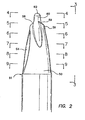
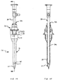
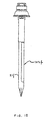
- a trocar system is illustrated in FIG. 1 and is designated by reference numeral 10.
- This system includes a cannula 12, defining a working channel 14, and a valve housing 16.
- the system 10 also includes an obturator 18 having a shaft 21 extending along an axis 23.
- a handle 25 is disposed at a proximal end of the shaft 21 while a blunt tip 27 is disposed at a distal end of the shaft 21.
- the shaft 21 of the obturator 18 is sized and configured for disposition within the working channel 14 of the cannula 12. With this disposition, the obturator 18 can be placed across a body wall such as the abdominal wall to provide the cannula 12 with access across the wall and into a body cavity, such as the peritoneal or abdominal cavity.
- the blunt tip 27 serves to direct the obturator 18 through the abdominal wall and the peritoneum, and can be removed with the obturator 18 once the cannula 12 is operatively disposed with the working channel 14 extending into the abdominal cavity.
- the diameter of the shaft 21 can range from about 3 mm to about 20 mm and is designed to fit within a trocar seal and the cannula 12.
- the tip 27 is provided with a blunt tip configuration.
- the blunt tip 27 takes into account the anatomical configuration of the abdominal wall with an improved structural design and method of insertion. To fully appreciate these aspects, it is helpful to initially discuss the anatomy associated with the abdominal wall.
- the abdominal wall typically includes a skin layer and a series of muscle layers, in addition to fat and fascia.
- the muscle layers are each defined by muscle fibers that extend generally parallel to each other in a direction that is different for each of the layers. For example, fibers of a first muscle layer and a second muscle layer may extend in directions that are generally 90 degrees off of each other.
- Such a structure may be separated or divaricated by an obturator having a blunt tip.
- the blunt tip may also include a twisted rectangular configuration to facilitate movement between the muscle fibers and layers. That is, the blunt tip is capable of being moved generally parallel to and between the fibers associated with a particular muscle layer.
- the fibers of the muscle layers may be oriented at different angles to each other such that proper alignment of the tip 27 for separation of one layer may not necessarily result in proper alignment for separation of the next layer.
- the obturator 18 has a blunt tip 27 to direct the obturator 18 through the different layers and a rectangular configuration that is twisted slightly so that separation of a first layer begins to rotate the distal end of the blunt tip 27 into proper orientation for separation of the next layer.
- the twisted configuration of the blunt tip 27 also causes the blunt tip 27 to function, for example, with the mechanical advantage of a screw thread.
- an exemplary method of placement requires that the user grip the handle 25 of the obturator 18 and twist it about the axis 23. This twisting motion in combination with the screw configuration of the blunt tip 27 converts radial movement into forward movement along the axis 23.
- the user applies both a forwardly directed force as well as a radial force to move the trocar system 10 in a forward direction.
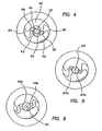
- the blunt tip 27 comprises generally of eight surfaces: two opposing surfaces 50 and 52, separated by two side surfaces 54 and 56, two end surfaces 58 and 59, a generally tapered surface 60 formed in surfaces 50 and 52 around axis 23 and extending beyond end surfaces 58 and 59, and a blunt surface 62.
- the surfaces 50 and 52, side surfaces 54 and 56, and tapered surface 60 generally define the cross-section of the blunt tip 27 from blunt surface 62 to proximal end 61. This configuration can best be appreciated with reference to the cross-section views of FIGS. 4-9 .
- the distal end of the blunt tip 27 is shown with a circle 64 having the smallest circular area and a rectangle 63 having the greatest length-to-width ratio.
- the rectangle 63 has a twisted, S-shaped configuration at end surfaces 58 and 59.
- the circle 64 becomes larger and the rectangle 63 becomes less twisted, and the width increases relative to the length of the rectangle 63.
- the spiral nature of the blunt tip 27 is also apparent as the circle 64 and rectangle 63 move counterclockwise around the axis 23. This is perhaps best appreciated in a comparison of the circle 64 and the rectangle 63 in FIG. 6 relative to that in FIG. 5 .
- the circle 64 begins to expand with increasing circular area and the rectangle 63 begins to widen with a reduction in the ratio of length to width.
- the long sides of the rectangle 63 also tend to become more arcuate as they approach a more rounded configuration most apparent in FIGS. 8 and 9 .
- the circle 64 and the rounded rectangle 63 become more circular with progressive proximal positions. Furthermore, the circle 64 expands at a lesser rate than the rectangle 63, which eventually absorbs the circle 64 as shown in FIGS. 8 and 9 . In these figures, it will also be apparent that the rotation of the rectangle 63 reaches a most counterclockwise position and then begins to move clockwise. This is best illustrated in FIGS. 7-9 . This back and forth rotation results from the configuration of the side surfaces 54 and 56, which in general are U-shaped as best illustrated in FIGS. 2 and 3 .
- the ratio of the length to width of the rectangle 63 is dependent on the configuration of the side surfaces 54 and 56, which define the short sides of the rectangle 63 as well as the configuration of the surfaces 50 and 52, which define the long sides of the rectangle 63.
- the side surfaces 54 and 56 are most narrow at the end surfaces 58 and 59.
- the side surfaces 54 and 56 extend proximally, they reach a maximum width near the point of the most counterclockwise rotation, shown generally in FIG. 8 , and then reduce in width as they approach the proximal end 61.
- the surfaces 50 and 52 transition from a generally flat configuration at the end surfaces 58 and 59 to a generally rounded configuration at the proximal end 61.
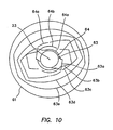
- the circle 64 is further designated with a lower case letter a, b or c, respectively; similarly, the rectangle 63 is further designated with a lower case letter a, b, c, d or e, respectively, in FIGS. 5-9 .
- the circles 64, 64a-64c and the rectangles 63, 63a-63e are superimposed on the axis 23 to show their relative sizes, shapes and angular orientations.
- the tip 27 With a generally tapered configuration at the distal end and a rectangular configuration at a distal portion of the tip, the tip 27 appears much like a flathead screwdriver having a blunt tip. More particularly, the tip 27 includes a tapered structure extending outward from the end surfaces 58 and 59 that serves to direct the obturator 18 through the tissue fibers.
- the lengths of the end surfaces 58 and 59 may be aligned parallel with the fibers of each muscle layer.
- a simple back and forth twisting motion of the blunt tip 27 tends to separate the fibers along natural lines of separation, opening the muscle layer to accept the larger diameter of the cannula 12.
- the tapered and twisted configuration of the blunt tip 27 directs and turns the rectangle 63 more into a parallel alignment with fibers in the next layer.
- the blunt tip 27 and the twisting or dithering motion facilitates an easy separation of the fibers requiring a significantly reduced insertion force.
- the device of the invention can be operated by rotating in alternating clockwise and counterclockwise directions while applying a downward force.
- rotating in alternating directions the tissue is moved apart and a larger opening is created for a profile of greater cross-sectional area to follow. This process continues safely as the device enters the peritoneal cavity and moves to its operative position.
- the size of the opening left in the tissue is minimal. Importantly, this opening is left with a small defect that does not require suturing due to a dilating effect caused by the mere separation of fibers. Since there are no sharp blades, sharp edges or piercing points to cut tissue fibers, the healing process is shortened.
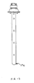
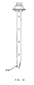
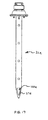
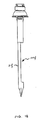
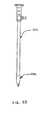
- the tip of the bladeless obturator 18 can be formed as a generally tapered shape 27a with a blunt distal end as illustrated in FIG. 11 , as a pyramidal shape 27b with a blunt distal end and blunt edges as illustrated in FIG. 12 , and as a fully radiused tip 27c for insertion through flaccid tissue or an existing body orifice such as the urethra as illustrated in FIG. 13 .
- the blunt tip 27 in accordance with the invention is formed from a transparent material.
- the blunt tip 27 can be formed from a plastic material or a glass material.
- the shaft 21 and the tip 27 are formed from a transparent polycarbonate material.
- the bladeless obturator 18 of the invention is designed to accommodate the insertion of a conventional laparoscope 30.
- the shaft 21 of the bladeless obturator 18 is hollow to allow for the insertion of the laparoscope 30 at an opening 32.
- the shaft 21 is sized and configured to allow the laparoscope 30 to slide within proximity of the tip 27 thus providing a viewing area through the tip 27.
- An endoscopic video camera (not shown) is typically connected to the laparoscope 30 and this combination is connected to a video monitor.
- a trocar is usually placed through the umbilicus of the patient.
- the placement of this trocar is typically performed in a blind fashion in that the surgeon cannot see where the tip of the trocar is as it is advanced through the abdominal wall and into the abdominal cavity of the patient. This results in a high degree of risk that the trocar may be inadvertently advanced too far into the abdomen of the patient resulting in trauma to vital organs and/or vessels.
- this risk is diminished as the surgeon is better able to determine when the trocar has traversed the abdominal wall.
- the tip 27 may be generally hollow or it may be substantially solid to receive the distal end of the laparoscope 30. In another aspect, the tip 27 may be a solid tip. The tip 27 may further comprise at least one portion that is marked differently from the rest of the tip to serve as an indicator, for example, of depth as the tip 27 is being inserted into the body tissue. The at least one portion may be opaque or marked with a different color from the rest of the tip 27.
- the shaft 21 and the tip 27 of the bladeless obturator 18 can accommodate a laparoscope with a non-angled lens, also known as a 0° laparoscope.
- the shaft 21 and the tip 27 can also accommodate a laparoscope with an angled lens such as a 30° laparoscope.
- the tip 27 is designed such that when either a 0° laparoscope or a 30° laparoscope is inserted therein, the lens of the laparoscope extends beyond a distal edge 36 of the cannula 12 thereby providing a clear and unobstructed view through the tip 27.
- the tip 27 further includes a ledge 39 that properly engages either the 0° laparoscope or the 30° laparoscope.
- the surgical access device of the present invention can provide a clear unobstructed view of body tissue through either a 0° or a 30° laparoscope, therefore obviating the need for a hospital to carry the additional inventory required to provide two laparoscopes for each laparoscopic surgical procedure, and obviating the need for a hospital to clean and sterilize a second laparoscope for each laparoscopic surgical procedure, and obviating the need to transfer the endoscopic video equipment from one laparoscope to the other laparoscope during each laparoscopic surgical procedure.
- the shaft 21 may include a tip with a bulbous section 27d to better accommodate the distal end of the angled lens laparoscope. By adding the bulbous section 27d, the distal end of the angled lens laparoscope would be closer to the tip of the obturator thereby improving visualization.
- the bladeless obturator can include integral fiber optic light fiber elements and an integral imaging element within the shaft and the tip of the obturator.
- the bladeless obturator with integral imaging means can be formed of reusable or disposable materials.
- the bladeless obturator 18 can be constructed as a single component or as multiple components such as the shaft 21 and the tip 27. If the obturator 18 is constructed as a single component, then it can be formed from either disposable or reusable materials. If the obturator 18 is constructed as two or more components, then each component can be formed from either disposable or reusable materials as desired for a particular configuration. In one aspect, the obturator 18 is constructed from a single reusable material such as metal (e.g., stainless steel) or an autoclavable polymer to facilitate re-sterilization. In another aspect, the obturator 18 is formed from a transparent steam sterilizable reusable plastic material such as polyphenylsulfone or polyetherimide. The blunt tip 27 can also be coated or otherwise constructed from a soft elastomeric material. In such a case, the material can be a solid elastomer or composite elastomer/ polymer.
- the shaft 21 can be formed so as to be partially or fully flexible.
- the obturator 18 can be inserted through a passageway containing one or more curves of virtually any shape. A partially or fully flexed obturator 18 can then be used with a flexible cannula 12 allowing greater access to an associated body cavity.
- the obturator 18 can include a separately molded tip 27 and a molded or extruded shaft 21 with the two components, as explained above, comprising of the same material or different materials.
- the tip 27 can then be attached to the shaft 21 by adhesive bonding, ultrasonic welding, snap-fitting, or with a shrink tube.
- the tip 27 can also be overmolded over the shaft 21 to mechanically lock the two components together.
- the tip 27 can be formed from a transparent material such as polycarbonate to enable visualization while the shaft 21 can be formed from either an opaque material or a transparent material.
- the shaft 21 can also be formed from a metal material.
- the obturator 18 can include a disposable tip that is releasably attached to a reusable shaft 21. Thus, a new tip 27 can be used for each procedure to provide optimal visualization through the tip 27 of the obturator 18 during each procedure.
- a shaft 21e including a cutout section 100e in the tip portion 27e that enables direct visualization of the body tissue as the tip 27e separates tissue fibers.
- the shaft 21 e can include a single or a plurality of cutouts 100e in the tip 27e or along the shaft of the obturator.
- a shaft 21f having a cutout portion 100f along the axial axis of the shaft 21 f.
- the shaft 21f has a cross-section of about 1 ⁇ 2-circle to about 3 ⁇ 4-circle and the cutout portion 100f has a cross-section of about 1 ⁇ 2-circle to about 1 ⁇ 4-circle.
- An advantage of this is the wall of the shaft 21 f can be a little thicker as a result of the cutout section, which makes injection molding of the shaft easier.
- a cover 102f that can be attached over the cutout portion 100f of the 1 ⁇ 2-circle shaft 21f as shown in FIG. 18 .
- a polycarbonate cover also with a 1 ⁇ 2-circle shaped cross-section can be attached to the shaft to form a tubular cross-section.
- An advantage of molding the tubular shaft 21 f in two pieces is increased manufacturability of the shaft 21 f.
- the cover 1 02f can be attached to the shaft 21 f with an adhesive bond, an ultrasonic weld, a snap-fit, or with a shrink tube.
- the obturator can be formed from two clam-shell components each including one-half of the shaft and tip configuration along the axial axis of the obturator.
- the two components can then be affixed together using an adhesive bond, an ultrasonic weld, an outer shrink tube, or a snap fit.
- a feature of the surgical access device of the invention is that the shaft 21 of the obturator 18 is designed to frictionally lock the laparoscope 30 in place using a laparoscope lock 40, which can be formed within the handle 25. More specifically, the laparoscope lock 40 prevents the laparoscope 30 from moving axially relative to the shaft 21 of the obturator 18 during handling within the sterile field and during insertion through a body wall but enables the laparoscope 30 to rotate freely relative to the shaft 21. This rotation of the lock 40 enables the trocar system 10 to be twisted during insertion into and through the abdominal wall while maintaining the laparoscope 30 in a fixed rotational position that provides for a stable viewing image on the video monitor.
- the conventional obturators with visualization properties include means for locking the laparoscope in place but these obturators lock the laparoscope both axially and rotationally.
- a drawback of the conventional devices is the viewing image on the video monitor is unstable if the trocar is twisted during insertion. More specifically, with prior art obturator laparoscope locks, if the trocar is twisted back and forth in a clockwise and counter-clockwise fashion, the laparoscope also moves clockwise and counter-clockwise with the trocar resulting in an oscillating and disorienting viewing image on the video monitor.
- the laparoscope lock 40 of the present invention improves visualization and enables a more precise placement of the trocar within the body tissue and across the body wall as compared to obturators of the prior art while preventing inadvertent axial movement of the laparoscope during handling and use.
- the bladeless obturator 18 further comprises a cap 42 that can be snap-fitted onto the proximal end of the obturator shaft 21, after which the laparoscope lock 40 can be snap-fitted onto the end of the cap 42.
- Both the cap 42 and the lock 40 can be formed of a plastic material such as polycarbonate.
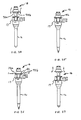
- the obturator cap 42 can be provided with and without a pistol-grip handle. The handled version of the bladeless obturator provides a pistol-grip to ease insertion of the trocar system as illustrated in FIGS. 22 and 23 .
- the pistol-grip handle is designed to nest into the handle on the trocar seal to prevent excessive flexure of the handle during insertion of the trocar as illustrated in FIG. 23 .
- the handled bladeless obturator includes three components comprising of an obturator shaft 21 b, an obturator cap 42b having a pistol-grip handle 26b, and a laparoscope lock 40b, all of which can be injection molded out of polycarbonate.
- the pistol-grip handle 26b can be formed with two components frictionally fitted together with, for example, interference pins. The interference pins can be fitted into holes in the handle 26b to affect a frictional lock between the two components.
- the bladeless obturator 18 is designed to releasably attach to a trocar seal 17 via two cantilever snap-fits 70a, 70b.
- the snap-fits 70a, 70b passively engage the trocar seal 17 and serve to axially lock the obturator 18 to the trocar seal 17 and cannula 12 ( FIGS. 24 and 25 ).
- the bladeless obturator 18 includes axial key members 74 at its proximal end which are designed to mate with axial keyways on the trocar seal 17.
- the obturator 18 As the bladeless obturator 18 is inserted into the trocar seal 17 and cannula 12, the obturator 18 is rotated slightly to align the axial key members 74 with the axial keyways and then advanced until the snap-fits 70a, 70b engage the trocar seal 17.
- the axial key members 74 serve to rotationally lock the obturator 18 to the trocar seal 17.
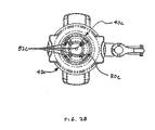
- the laparoscope lock 40c comprising a multiple-finger collet 80c comprising a plurality of fingers 82c.
- the multiple-finger collet 80c has an inner diameter that is smaller than the outer diameter of the laparoscope.
- the fingers 82c of the collet 80c spread open during insertion of the laparoscope providing frictional engagement with the outer diameter of the laparoscope.
- the laparoscope lock 40c is free to rotate on an obturator cap 42c, and allows the laparoscope to freely rotate relative to the shaft of the bladeless obturator.
- the obturator shaft 21 of the bladeless obturator 18 can be configured with a barb 76 at its proximal end.
- the barb 76 is vertically slotted to enable the shaft 21 to flex during assembly.
- the obturator shaft 21 may also include a plurality of keys (not shown) near its proximal end.
- the obturator cap 42 is configured to axially slide over the barb 76 on the obturator shaft 21 to affect a one-way snap-fit lock between the two components. This snap-fit prevents the removal of the obturator cap 42 from the obturator shaft 21.
- the obturator cap 42 may further include keyways (not shown) that engage the keys on the obturator shaft 21 to rotationally index the components together.
- the obturator cap 42 may further include a second barb (not shown) at its proximal end.
- the laparoscope lock 40 may include a plurality of tabs (not shown) that are designed to spread and axially slide over the second barb on the obturator cap 42 to affect a one-way snap-fit lock between the obturator cap 42 and the laparoscope lock 40. This snap-fit prevents the axial removal of the laparoscope lock 40 from the obturator cap 42.
- the laparoscope lock 40 is free to rotate relative to the obturator cap 42.
- a laparoscope 30a having a tip 33a configured similar to that of the tip 27 of the bladeless obturator 18 described above, the tip 33a being adapted to snap-fit or frictionally engage the end of the laparoscope 30a.
- the combination of the tip 33a and the laparoscope 30a serve to form an optical obturator having a blunt tip.
- the bladeless tip 33a can then be removed from the laparoscope 30a.
- the bladeless tip 33a can be formed from either a disposable or reusable transparent material.
- the bladeless tip 33a can be temporarily or permanently affixed to the scope 30a by any of the known methods of attaching the two components together as explained above.
- a laparoscope lock 40d in accordance with of the invention including an active lock comprising a camming member 43d.
- the laparascope would first be inserted into the shaft of the obturator and then the lock 40d would be activated to lock the laparoscope in an axial position relative to the shaft.
- the lock 40d can rotate freely to enable the laparoscope to rotate freely relative to the shaft.
- a lock 40e can include an active lock comprising a clamping member 45e.
- the laparascope would first be inserted into the shaft of the obturator and then the lock would be activated to lock the laparoscope in an axial position relative to the shaft.
- the lock 40e can rotate freely to enable the laparoscope to rotate freely relative to the shaft.
- a lock 40f in accordance with another embodiment of the invention including an active lock comprising a locking collar 46 positioned eccentrically with respect to the axis of the obturator so that as the locking collar 46 is turned, a frictional engagement with the laparoscope is affected.
- the laparoscope would first be inserted into the locking collar 46 and the shaft of the obturator, the locking collar 46 can then be turned to frictionally engage the laparoscope.
- the laparoscope lock 40f can rotate freely to enable the laparoscope to rotate freely relative to the shaft.
- a laparoscope lock 40g including an active lock comprising of a locking nut 48 and a thread.
- the threaded portion of the lock 40g has flexible elements similar to those on a collet.
- the laparoscope would first be inserted into the threaded portion of the lock 40g and the nut then rotated clockwise to collapse the flexible elements to frictionally engage the laparoscope. To release the laparoscope, the nut is rotated counter-clockwise.
- the laparoscope lock can include a lock that includes an elastomeric element.
- the addition of the elastomeric element can enhance the frictional engagement with the laparoscope.
- An example of such an elastomeric element is a silicone O-ring sized with an inside diameter smaller than the outside diameter of the laparoscope.
- the laparoscope lock can either rotate freely to enable the laparoscope to rotate freely relative to the shaft
- An insufflation needle having a passageway and valve can be used to administer carbon dioxide or other insufflation gas to the peritoneal cavity.
- the obturator 18 can also be used with an insufflation needle cannula in which case removal of the obturator 18 upon entry would allow for rapid insufflation of the peritoneal cavity.
- the bladeless obturator can be formed with a 2-3 mm outer diameter and with a small thru-hole at its distal end.
- the bladeless obturator can be used in conjunction with a miniaturized laparoscope to provide initial access into a hollow bodycavity. Once access is obtained, the laparoscope can be removed from the bladeless obturator and an insufflation gas such as carbon dioxide can be dispensed through the obturator into the hollow body cavity.
- the bladeless obturator can also include holes in the tip portion to enhance the flow of insufflation gases though the obturator.
- the bladeless obturator can be formed with a 2-3 mm outer diameter and used in conjunction with a miniaturized laparoscope to provide initial access into a hollow body cavity. After access is obtained, the bladeless obturator can be removed from the trocar cannula and an insufflation gas such as carbon dioxide can be dispensed though the cannula and into the hollow body cavity.
- an insufflation gas such as carbon dioxide
Description
- This invention generally relates to trocar systems including obturators and, more specifically, to blunt tip obturators having hollow shafts for insertion of optical instruments.
- Trocar systems have been of particular advantage in facilitating less invasive surgery across a body wall and within a body cavity. This is particularly true in abdominal surgery where trocars have provided a working channel across the abdominal wall to facilitate the use of instruments within the abdominal cavity.
- The trocar systems of the past typically included a cannula, which provides the working channel, and an obturator which is used to place the cannula across the abdominal wall. The obturator is inserted into the working channel of the cannula and then pushed through the abdominal wall with a penetration force of sufficient magnitude resulting in penetration of the abdominal wall. Once the cannula is in place, the obturator can be removed.
- Obturators have been developed with an attempt to reduce the penetration force of the abdominal wall. For example, sharp blades, sharp edges and piercing points have typically been used to enable the obturator to cut or pierce its way through the abdominal wall. While the sharp blades, sharp edges and piercing points have facilitated a reduced penetration force, they have also caused larger trocar site defects. These trocar site defects may have to be sutured closed resulting in increased operating room costs and procedural time. Moreover, once the abdominal wall has been penetrated, the sharp blades, sharp edges and piercing points of the obturator may still cause damage to the vessels and organs that lie within the peritoneal cavity. For example, the blades on the obturators that serve to cut tissue during insertion may also cut vessels or puncture organs that may result in patient injury or surgical complications.
- Known obturators that can accommodate a laparoscope to permit viewing through a transparent tip are disclosed in International Patent Applications
WO 03/026512 WO 96/01074 - There remains a need in the art for an improved surgical access device that separates tissue during insertion through a body wall. With a transparent blunt tip obturator having a hollow shaft to enable insertion of an optical instrument to view the insertion of the obturator through the body wall.
- According to the present invention there is provided a surgical access device comprising: a tissue separating obturator comprising: an elongate shaft portion extending along a longitudinal axis and defining a first lumen between an open proximal end and a distal end; and a transparent distal tip portion with an inner surface and an outer surface adapted for penetrating tissue; the distal tip portion disposed at the distal end of the shaft portion; at least part of the tip portion having a generally tapered configuration; wherein the first lumen is sized and configured to receive an optical instrument having a distal end adapted to receive an image and the tip portion being adapted to permit passage of an image; and characterized by a lock disposed at the proximal end of the shaft portion configured to allow the optical instrument to rotate freely inside and relative to the elongate shaft of the obturator while restraining the optical instrument inserted into the first lumen from moving axially relative to the obturator.
- These and other features of the invention will become more apparent with a discussion of the various embodiments in reference to the associated drawings.
- The accompanying drawings explain the features and principles of the invention. In the drawings:
-
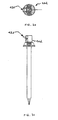
FIGS. 1A and 1 B illustrate side views of a trocar system including a cannula with associated valve housing, and an obturator with a blunt tip extending through the working channel of the cannula to facilitate placement across the abdominal wall; -
FIG. 2 is a side elevation view of the blunt tip of the obturator of the invention; -
FIG. 3 is a side elevation view of the blunt tip taken along line 3-3 ofFIG. 2 ; -
FIG. 4 is an end view taken along line 4-4 ofFIG. 2 ; -
FIG. 5 is a radial cross-section view taken along line 5-5 ofFIG. 2 ; -
FIG. 6 is a radial cross-section view taken along line 6-6 ofFIG. 2 ; -
FIG. 7 is a radial cross-section view taken along line 7-7 ofFIG. 2 ; -
FIG. 8 is a radial cross-section view taken along line 8-8 ofFIG. 2 ; -
FIG. 9 is a radial cross-section view taken along line 9-9 ofFIG. 2 ; -
FIG. 10 is a schematic view illustrating each of theFIGS. 4-9 superimposed to facilitate an understanding of the blunt tip and its twisted configuration; -
FIG. 11 illustrates a side view of a bladeless obturator of the invention having a tip formed as a blunt tapered shape; -
FIG. 12 illustrates a side view of a bladeless obturator of the invention having a tip formed as a pyramidal shape; -
FIG. 13 illustrates a side view of a bladeless obturator of the invention having a fully radiused tip; -
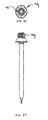
FIGS. 14 and 15 illustrate a side view and a cross-section view, respectively, of the trocar system ofFIGS. 1 A and 1 B and further illustrating the insertion of a laparoscope; -
FIG. 16 illustrates a side view of a bladeless obturator of the invention having a bulbous tip; -
FIG. 17 illustrates a side view of a bladeless obturator of the invention having a tip with a cutout section; -
FIG. 18 illustrates a side view of a bladeless obturator of the invention having a shaft with a cutout section; -
FIG. 19 illustrates a side view of a bladeless obturator of the invention and a cover for the cutout section of the shaft ofFIG. 18 ; -
FIGS. 20 and 21 illustrate side views of a bladeless obturator of the invention having a laparoscope lock; -
FIGS. 22 and 23 illustrate side views of a bladeless obturator of the invention including a cap with pistol-grip handle; -
FIGS. 24 and 25 illustrate the locking mechanism between the bladeless obturator and the trocar seal of the invention; -
FIGS. 26 and 27 illustrate the release mechanism between the bladeless obturator and the trocar seal of the invention; -
FIG. 28 illustrates a top view of a laparoscope lock of the invention comprising a multiple-finger collet; -
FIG. 29 illustrates an optical instrument having a transparent bladeless tip of the invention; -
FIGS. 30 and 31 illustrate a top view and a side view, respectively, of a laparoscope lock of the invention comprising a camming member; -
FIGS. 32 and 33 illustrate a top view and a side view, respectively, of a laparoscope lock of the invention comprising a clamping member; -
FIGS. 34 and 35 illustrate a top view and a side view, respectively, of a laparoscope lock of the invention comprising a locking collar; and -
FIGS. 36 and 37 illustrate a top view and a side view, respectively, of a laparoscope lock of the invention comprising a locking nut and thread. - A trocar system is illustrated in
FIG. 1 and is designated byreference numeral 10. This system includes acannula 12, defining a workingchannel 14, and avalve housing 16. Thesystem 10 also includes anobturator 18 having ashaft 21 extending along anaxis 23. Ahandle 25 is disposed at a proximal end of theshaft 21 while ablunt tip 27 is disposed at a distal end of theshaft 21. Theshaft 21 of theobturator 18 is sized and configured for disposition within the workingchannel 14 of thecannula 12. With this disposition, theobturator 18 can be placed across a body wall such as the abdominal wall to provide thecannula 12 with access across the wall and into a body cavity, such as the peritoneal or abdominal cavity. Theblunt tip 27 serves to direct theobturator 18 through the abdominal wall and the peritoneum, and can be removed with theobturator 18 once thecannula 12 is operatively disposed with the workingchannel 14 extending into the abdominal cavity. The diameter of theshaft 21 can range from about 3 mm to about 20 mm and is designed to fit within a trocar seal and thecannula 12. - The
tip 27 is provided with a blunt tip configuration. Theblunt tip 27 takes into account the anatomical configuration of the abdominal wall with an improved structural design and method of insertion. To fully appreciate these aspects, it is helpful to initially discuss the anatomy associated with the abdominal wall. The abdominal wall typically includes a skin layer and a series of muscle layers, in addition to fat and fascia. The muscle layers are each defined by muscle fibers that extend generally parallel to each other in a direction that is different for each of the layers. For example, fibers of a first muscle layer and a second muscle layer may extend in directions that are generally 90 degrees off of each other. - Having noted the directional nature of the muscle fibers, it can be appreciated that such a structure may be separated or divaricated by an obturator having a blunt tip. The blunt tip may also include a twisted rectangular configuration to facilitate movement between the muscle fibers and layers. That is, the blunt tip is capable of being moved generally parallel to and between the fibers associated with a particular muscle layer.
- As described earlier, the fibers of the muscle layers may be oriented at different angles to each other such that proper alignment of the
tip 27 for separation of one layer may not necessarily result in proper alignment for separation of the next layer. For at least this reason, theobturator 18 has ablunt tip 27 to direct theobturator 18 through the different layers and a rectangular configuration that is twisted slightly so that separation of a first layer begins to rotate the distal end of theblunt tip 27 into proper orientation for separation of the next layer. - The twisted configuration of the
blunt tip 27 also causes theblunt tip 27 to function, for example, with the mechanical advantage of a screw thread. With this configuration, an exemplary method of placement requires that the user grip thehandle 25 of theobturator 18 and twist it about theaxis 23. This twisting motion in combination with the screw configuration of theblunt tip 27 converts radial movement into forward movement along theaxis 23. Thus, the user applies both a forwardly directed force as well as a radial force to move thetrocar system 10 in a forward direction. - The twisted configuration of the
blunt tip 27 is most apparent in the side elevation views ofFIGS. 2 and3 . In this embodiment, theblunt tip 27 comprises generally of eight surfaces: two opposingsurfaces side surfaces end surfaces surface 60 formed insurfaces axis 23 and extending beyond end surfaces 58 and 59, and ablunt surface 62. - The
surfaces surface 60 generally define the cross-section of theblunt tip 27 fromblunt surface 62 toproximal end 61. This configuration can best be appreciated with reference to the cross-section views ofFIGS. 4-9 . InFIG. 4 , the distal end of theblunt tip 27 is shown with acircle 64 having the smallest circular area and arectangle 63 having the greatest length-to-width ratio. Therectangle 63 has a twisted, S-shaped configuration at end surfaces 58 and 59. - As views are taken along progressive proximal cross-sections, it can be seen that the
circle 64 becomes larger and therectangle 63 becomes less twisted, and the width increases relative to the length of therectangle 63. The spiral nature of theblunt tip 27 is also apparent as thecircle 64 andrectangle 63 move counterclockwise around theaxis 23. This is perhaps best appreciated in a comparison of thecircle 64 and therectangle 63 inFIG. 6 relative to that inFIG. 5 . With progressive proximal positions, thecircle 64 begins to expand with increasing circular area and therectangle 63 begins to widen with a reduction in the ratio of length to width. The long sides of therectangle 63 also tend to become more arcuate as they approach a more rounded configuration most apparent inFIGS. 8 and 9 . That is, thecircle 64 and therounded rectangle 63 become more circular with progressive proximal positions. Furthermore, thecircle 64 expands at a lesser rate than therectangle 63, which eventually absorbs thecircle 64 as shown inFIGS. 8 and 9 . In these figures, it will also be apparent that the rotation of therectangle 63 reaches a most counterclockwise position and then begins to move clockwise. This is best illustrated inFIGS. 7-9 . This back and forth rotation results from the configuration of the side surfaces 54 and 56, which in general are U-shaped as best illustrated inFIGS. 2 and3 . - The ratio of the length to width of the
rectangle 63 is dependent on the configuration of the side surfaces 54 and 56, which define the short sides of therectangle 63 as well as the configuration of thesurfaces rectangle 63. Again with reference toFIGS. 2 and3 , it can be seen that the side surfaces 54 and 56 are most narrow at the end surfaces 58 and 59. As the side surfaces 54 and 56 extend proximally, they reach a maximum width near the point of the most counterclockwise rotation, shown generally inFIG. 8 , and then reduce in width as they approach theproximal end 61. Along this same distal to proximal path, thesurfaces proximal end 61. - In the progressive views of
FIGS. 5-7 , thecircle 64 is further designated with a lower case letter a, b or c, respectively; similarly, therectangle 63 is further designated with a lower case letter a, b, c, d or e, respectively, inFIGS. 5-9 . InFIG. 10 , thecircles rectangles axis 23 to show their relative sizes, shapes and angular orientations. - With a generally tapered configuration at the distal end and a rectangular configuration at a distal portion of the tip, the
tip 27 appears much like a flathead screwdriver having a blunt tip. More particularly, thetip 27 includes a tapered structure extending outward from the end surfaces 58 and 59 that serves to direct theobturator 18 through the tissue fibers. - In one aspect, the lengths of the end surfaces 58 and 59 may be aligned parallel with the fibers of each muscle layer. A simple back and forth twisting motion of the
blunt tip 27 tends to separate the fibers along natural lines of separation, opening the muscle layer to accept the larger diameter of thecannula 12. Once the first layer is substantially separated, the tapered and twisted configuration of theblunt tip 27 directs and turns therectangle 63 more into a parallel alignment with fibers in the next layer. Again, theblunt tip 27 and the twisting or dithering motion facilitates an easy separation of the fibers requiring a significantly reduced insertion force. - This facilitates a unique method of separating tissue and can be applied to any object with a blunt tip and generally flat sides. In particular, the device of the invention can be operated by rotating in alternating clockwise and counterclockwise directions while applying a downward force. When rotating in alternating directions, the tissue is moved apart and a larger opening is created for a profile of greater cross-sectional area to follow. This process continues safely as the device enters the peritoneal cavity and moves to its operative position.
- When the
cannula 12 is ultimately removed, the size of the opening left in the tissue is minimal. Importantly, this opening is left with a small defect that does not require suturing due to a dilating effect caused by the mere separation of fibers. Since there are no sharp blades, sharp edges or piercing points to cut tissue fibers, the healing process is shortened. It is appreciated that the tip of thebladeless obturator 18 can be formed as a generally tapered shape 27a with a blunt distal end as illustrated inFIG. 11 , as a pyramidal shape 27b with a blunt distal end and blunt edges as illustrated inFIG. 12 , and as a fully radiused tip 27c for insertion through flaccid tissue or an existing body orifice such as the urethra as illustrated inFIG. 13 . - The
blunt tip 27 in accordance with the invention is formed from a transparent material. Theblunt tip 27 can be formed from a plastic material or a glass material. In one aspect, theshaft 21 and thetip 27 are formed from a transparent polycarbonate material. - Referring to
FIGS. 14 and 15 , thebladeless obturator 18 of the invention is designed to accommodate the insertion of aconventional laparoscope 30. In particular, theshaft 21 of thebladeless obturator 18 is hollow to allow for the insertion of thelaparoscope 30 at anopening 32. Theshaft 21 is sized and configured to allow thelaparoscope 30 to slide within proximity of thetip 27 thus providing a viewing area through thetip 27. An endoscopic video camera (not shown) is typically connected to thelaparoscope 30 and this combination is connected to a video monitor. By enabling the positioning of theconventional laparoscope 30 within thetip 27 of thebladeless obturator 18, it is possible to visually observe body tissue as it is being separated by thetrocar system 10. Visualization of body tissue as it is being separated by thetrocar system 10 allows a surgeon to monitor the advancement of thetrocar system 10 and to avoid traumatizing vessels or organs. For example, during a laparoscopic cholecystectomy, a trocar is usually placed through the umbilicus of the patient. The placement of this trocar is typically performed in a blind fashion in that the surgeon cannot see where the tip of the trocar is as it is advanced through the abdominal wall and into the abdominal cavity of the patient. This results in a high degree of risk that the trocar may be inadvertently advanced too far into the abdomen of the patient resulting in trauma to vital organs and/or vessels. By providing a trocar system with visualization properties, this risk is diminished as the surgeon is better able to determine when the trocar has traversed the abdominal wall. - It is appreciated that the
tip 27 may be generally hollow or it may be substantially solid to receive the distal end of thelaparoscope 30. In another aspect, thetip 27 may be a solid tip. Thetip 27 may further comprise at least one portion that is marked differently from the rest of the tip to serve as an indicator, for example, of depth as thetip 27 is being inserted into the body tissue. The at least one portion may be opaque or marked with a different color from the rest of thetip 27. - The
shaft 21 and thetip 27 of thebladeless obturator 18 can accommodate a laparoscope with a non-angled lens, also known as a 0° laparoscope. Theshaft 21 and thetip 27 can also accommodate a laparoscope with an angled lens such as a 30° laparoscope. Thetip 27 is designed such that when either a 0° laparoscope or a 30° laparoscope is inserted therein, the lens of the laparoscope extends beyond adistal edge 36 of thecannula 12 thereby providing a clear and unobstructed view through thetip 27. Thetip 27 further includes aledge 39 that properly engages either the 0° laparoscope or the 30° laparoscope. - It should be noted that conventional trocars with visualization properties typically require a 0° laparoscope for insertion of the trocars and a 30° laparoscope for viewing anatomical structures during the remainder of the laparoscopic procedure. This requires the operating staff to provide two laparoscopes for the laparoscopic procedure, which increases hospital inventory costs and surgical preparation costs relating to cleaning and sterilization of the laparoscopes. In addition, because two laparoscopes are required for the laparoscopic procedure, there is additional operating room time required during the surgical procedure to transfer the endoscopic video camera from the 0° laparoscope to the 30° laparoscope which results in increased operating room costs for the hospital.
- The surgical access device of the present invention can provide a clear unobstructed view of body tissue through either a 0° or a 30° laparoscope, therefore obviating the need for a hospital to carry the additional inventory required to provide two laparoscopes for each laparoscopic surgical procedure, and obviating the need for a hospital to clean and sterilize a second laparoscope for each laparoscopic surgical procedure, and obviating the need to transfer the endoscopic video equipment from one laparoscope to the other laparoscope during each laparoscopic surgical procedure. Referring to
FIG. 16 , theshaft 21 may include a tip with abulbous section 27d to better accommodate the distal end of the angled lens laparoscope. By adding thebulbous section 27d, the distal end of the angled lens laparoscope would be closer to the tip of the obturator thereby improving visualization. - The bladeless obturator can include integral fiber optic light fiber elements and an integral imaging element within the shaft and the tip of the obturator. The bladeless obturator with integral imaging means can be formed of reusable or disposable materials.
- The
bladeless obturator 18 can be constructed as a single component or as multiple components such as theshaft 21 and thetip 27. If theobturator 18 is constructed as a single component, then it can be formed from either disposable or reusable materials. If theobturator 18 is constructed as two or more components, then each component can be formed from either disposable or reusable materials as desired for a particular configuration. In one aspect, theobturator 18 is constructed from a single reusable material such as metal (e.g., stainless steel) or an autoclavable polymer to facilitate re-sterilization. In another aspect, theobturator 18 is formed from a transparent steam sterilizable reusable plastic material such as polyphenylsulfone or polyetherimide. Theblunt tip 27 can also be coated or otherwise constructed from a soft elastomeric material. In such a case, the material can be a solid elastomer or composite elastomer/ polymer. - It is further appreciated that the
shaft 21 can be formed so as to be partially or fully flexible. With this configuration, theobturator 18 can be inserted through a passageway containing one or more curves of virtually any shape. A partially or fully flexedobturator 18 can then be used with aflexible cannula 12 allowing greater access to an associated body cavity. - The
obturator 18 can include a separately moldedtip 27 and a molded or extrudedshaft 21 with the two components, as explained above, comprising of the same material or different materials. Thetip 27 can then be attached to theshaft 21 by adhesive bonding, ultrasonic welding, snap-fitting, or with a shrink tube. Thetip 27 can also be overmolded over theshaft 21 to mechanically lock the two components together. Thetip 27 can be formed from a transparent material such as polycarbonate to enable visualization while theshaft 21 can be formed from either an opaque material or a transparent material. Theshaft 21 can also be formed from a metal material. - The
obturator 18 can include a disposable tip that is releasably attached to areusable shaft 21. Thus, anew tip 27 can be used for each procedure to provide optimal visualization through thetip 27 of theobturator 18 during each procedure. - Referring to
FIG. 17 , there is shown ashaft 21e including a cutout section 100e in thetip portion 27e that enables direct visualization of the body tissue as thetip 27e separates tissue fibers. By providing an obturator with cutout sections, the reflection of light from the laparoscope is minimized and the visibility of the tissue through the laparoscope is improved as compared to a design where visualization occurs through a plastic or glass window. It is appreciated that theshaft 21 e can include a single or a plurality of cutouts 100e in thetip 27e or along the shaft of the obturator. - Referring to
FIG. 18 , there is shown a shaft 21f having acutout portion 100f along the axial axis of the shaft 21 f. The shaft 21f has a cross-section of about ½-circle to about ¾-circle and thecutout portion 100f has a cross-section of about ½-circle to about ¼-circle. An advantage of this is the wall of the shaft 21 f can be a little thicker as a result of the cutout section, which makes injection molding of the shaft easier. - Referring to
FIG. 19 , there is shown a cover 102f that can be attached over thecutout portion 100f of the ½-circle shaft 21f as shown inFIG. 18 . In particular, a polycarbonate cover also with a ½-circle shaped cross-section can be attached to the shaft to form a tubular cross-section. An advantage of molding the tubular shaft 21 f in two pieces is increased manufacturability of the shaft 21 f. The cover 1 02f can be attached to the shaft 21 f with an adhesive bond, an ultrasonic weld, a snap-fit, or with a shrink tube. - In another aspect, the obturator can be formed from two clam-shell components each including one-half of the shaft and tip configuration along the axial axis of the obturator. The two components can then be affixed together using an adhesive bond, an ultrasonic weld, an outer shrink tube, or a snap fit.
- Referring to
FIGS. 20 and 21 , a feature of the surgical access device of the invention is that theshaft 21 of theobturator 18 is designed to frictionally lock thelaparoscope 30 in place using alaparoscope lock 40, which can be formed within thehandle 25. More specifically, thelaparoscope lock 40 prevents the laparoscope 30 from moving axially relative to theshaft 21 of theobturator 18 during handling within the sterile field and during insertion through a body wall but enables thelaparoscope 30 to rotate freely relative to theshaft 21. This rotation of thelock 40 enables thetrocar system 10 to be twisted during insertion into and through the abdominal wall while maintaining thelaparoscope 30 in a fixed rotational position that provides for a stable viewing image on the video monitor. - The conventional obturators with visualization properties include means for locking the laparoscope in place but these obturators lock the laparoscope both axially and rotationally. A drawback of the conventional devices is the viewing image on the video monitor is unstable if the trocar is twisted during insertion. More specifically, with prior art obturator laparoscope locks, if the trocar is twisted back and forth in a clockwise and counter-clockwise fashion, the laparoscope also moves clockwise and counter-clockwise with the trocar resulting in an oscillating and disorienting viewing image on the video monitor. The laparoscope lock 40 of the present invention improves visualization and enables a more precise placement of the trocar within the body tissue and across the body wall as compared to obturators of the prior art while preventing inadvertent axial movement of the laparoscope during handling and use.
- In another aspect of the invention as illustrated in
FIGS. 20 and 21 , thebladeless obturator 18 further comprises acap 42 that can be snap-fitted onto the proximal end of theobturator shaft 21, after which thelaparoscope lock 40 can be snap-fitted onto the end of thecap 42. Both thecap 42 and thelock 40 can be formed of a plastic material such as polycarbonate. Theobturator cap 42 can be provided with and without a pistol-grip handle. The handled version of the bladeless obturator provides a pistol-grip to ease insertion of the trocar system as illustrated inFIGS. 22 and 23 . The pistol-grip handle is designed to nest into the handle on the trocar seal to prevent excessive flexure of the handle during insertion of the trocar as illustrated inFIG. 23 . More particularly, the handled bladeless obturator includes three components comprising of an obturator shaft 21 b, anobturator cap 42b having a pistol-grip handle 26b, and a laparoscope lock 40b, all of which can be injection molded out of polycarbonate. The pistol-grip handle 26b can be formed with two components frictionally fitted together with, for example, interference pins. The interference pins can be fitted into holes in the handle 26b to affect a frictional lock between the two components. - Referring to
FIG. 24 , thebladeless obturator 18 is designed to releasably attach to atrocar seal 17 via two cantilever snap-fits 70a, 70b. As theobturator 18 is inserted into thetrocar seal 17 andcannula 12, the snap-fits 70a, 70b passively engage thetrocar seal 17 and serve to axially lock theobturator 18 to thetrocar seal 17 and cannula 12 (FIGS. 24 and 25 ). To release theobturator 18 from thetrocar seal 17 andcannula 12,outboard tabs 72a, 72b on theobturator cap 42 are depressed inwardly and theobturator 18 is then free to be slidably removed as illustrated inFIGS. 26 and 27 . Referring back toFIGS. 20 and 21 , thebladeless obturator 18 includes axialkey members 74 at its proximal end which are designed to mate with axial keyways on thetrocar seal 17. As thebladeless obturator 18 is inserted into thetrocar seal 17 andcannula 12, theobturator 18 is rotated slightly to align the axialkey members 74 with the axial keyways and then advanced until the snap-fits 70a, 70b engage thetrocar seal 17. The axialkey members 74 serve to rotationally lock theobturator 18 to thetrocar seal 17. - Referring to
FIG. 28 , there is shown another embodiment of thelaparoscope lock 40c comprising a multiple-finger collet 80c comprising a plurality of fingers 82c. The multiple-finger collet 80c has an inner diameter that is smaller than the outer diameter of the laparoscope. The fingers 82c of the collet 80c spread open during insertion of the laparoscope providing frictional engagement with the outer diameter of the laparoscope. Thelaparoscope lock 40c is free to rotate on anobturator cap 42c, and allows the laparoscope to freely rotate relative to the shaft of the bladeless obturator. - Referring back to
FIGS. 20 and 21 , theobturator shaft 21 of thebladeless obturator 18 can be configured with abarb 76 at its proximal end. Thebarb 76 is vertically slotted to enable theshaft 21 to flex during assembly. Theobturator shaft 21 may also include a plurality of keys (not shown) near its proximal end. Theobturator cap 42 is configured to axially slide over thebarb 76 on theobturator shaft 21 to affect a one-way snap-fit lock between the two components. This snap-fit prevents the removal of theobturator cap 42 from theobturator shaft 21. Theobturator cap 42 may further include keyways (not shown) that engage the keys on theobturator shaft 21 to rotationally index the components together. Theobturator cap 42 may further include a second barb (not shown) at its proximal end. Thelaparoscope lock 40 may include a plurality of tabs (not shown) that are designed to spread and axially slide over the second barb on theobturator cap 42 to affect a one-way snap-fit lock between theobturator cap 42 and thelaparoscope lock 40. This snap-fit prevents the axial removal of the laparoscope lock 40 from theobturator cap 42. Thelaparoscope lock 40 is free to rotate relative to theobturator cap 42. - Referring to
FIG. 29 , there is shown a laparoscope 30a having atip 33a configured similar to that of thetip 27 of thebladeless obturator 18 described above, thetip 33a being adapted to snap-fit or frictionally engage the end of the laparoscope 30a. With this configuration, the combination of thetip 33a and the laparoscope 30a serve to form an optical obturator having a blunt tip. Once the trocar is inserted and the laparoscope removed from the trocar seal and cannula, thebladeless tip 33a can then be removed from the laparoscope 30a. Thebladeless tip 33a can be formed from either a disposable or reusable transparent material. Thebladeless tip 33a can be temporarily or permanently affixed to the scope 30a by any of the known methods of attaching the two components together as explained above. - Referring to
FIGS. 30 and 31 , there is shown alaparoscope lock 40d in accordance with of the invention including an active lock comprising acamming member 43d. With this type of lock, the laparascope would first be inserted into the shaft of the obturator and then thelock 40d would be activated to lock the laparoscope in an axial position relative to the shaft. Thelock 40d can rotate freely to enable the laparoscope to rotate freely relative to the shaft. In another aspect as illustrated inFIGS. 32 and 33 , alock 40e can include an active lock comprising a clampingmember 45e. With this type of lock, the laparascope would first be inserted into the shaft of the obturator and then the lock would be activated to lock the laparoscope in an axial position relative to the shaft. Thelock 40e can rotate freely to enable the laparoscope to rotate freely relative to the shaft. - Referring to
FIGS. 34 and 35 , there is shown alock 40f in accordance with another embodiment of the invention including an active lock comprising alocking collar 46 positioned eccentrically with respect to the axis of the obturator so that as the lockingcollar 46 is turned, a frictional engagement with the laparoscope is affected. The laparoscope would first be inserted into the lockingcollar 46 and the shaft of the obturator, the lockingcollar 46 can then be turned to frictionally engage the laparoscope. Thelaparoscope lock 40f can rotate freely to enable the laparoscope to rotate freely relative to the shaft. - In
FIGS. 36 and 37 , there is shown a laparoscope lock 40g including an active lock comprising of a lockingnut 48 and a thread. The threaded portion of the lock 40g has flexible elements similar to those on a collet. The laparoscope would first be inserted into the threaded portion of the lock 40g and the nut then rotated clockwise to collapse the flexible elements to frictionally engage the laparoscope. To release the laparoscope, the nut is rotated counter-clockwise. - In another aspect, the laparoscope lock can include a lock that includes an elastomeric element. The addition of the elastomeric element can enhance the frictional engagement with the laparoscope. An example of such an elastomeric element is a silicone O-ring sized with an inside diameter smaller than the outside diameter of the laparoscope. The laparoscope lock can either rotate freely to enable the laparoscope to rotate freely relative to the shaft
- An insufflation needle having a passageway and valve can be used to administer carbon dioxide or other insufflation gas to the peritoneal cavity. The
obturator 18 can also be used with an insufflation needle cannula in which case removal of theobturator 18 upon entry would allow for rapid insufflation of the peritoneal cavity. - The bladeless obturator can be formed with a 2-3 mm outer diameter and with a small thru-hole at its distal end. The bladeless obturator can be used in conjunction with a miniaturized laparoscope to provide initial access into a hollow bodycavity. Once access is obtained, the laparoscope can be removed from the bladeless obturator and an insufflation gas such as carbon dioxide can be dispensed through the obturator into the hollow body cavity. The bladeless obturator can also include holes in the tip portion to enhance the flow of insufflation gases though the obturator. More particularly, the bladeless obturator can be formed with a 2-3 mm outer diameter and used in conjunction with a miniaturized laparoscope to provide initial access into a hollow body cavity. After access is obtained, the bladeless obturator can be removed from the trocar cannula and an insufflation gas such as carbon dioxide can be dispensed though the cannula and into the hollow body cavity.
- It will be understood that many modifications can be made to the disclosed embodiments without departing from the scope of the invention as defined in appended claim 1. For example, various sizes of the surgical device are contemplated as well as various types of constructions and materials. It will also be apparent that many modifications can be made to the configuration of parts as well as their interaction. For these reasons, the above description should not be construed as limiting the invention, but should be interpreted as merely exemplary of preferred embodiments.
Claims (19)
- A surgical access device comprising:a tissue separating obturator (18) comprising:an elongate shaft portion (21) extending along a longitudinal axis (23) and defining a first lumen between an open proximal end and a distal end; anda transparent distal tip portion (27) with an inner surface and an outer surface adapted for penetrating tissue; the distal tip portion (27) disposed at the distal end of the shaft portion (21); at least part of the tip portion (27) having a generally tapered configuration;wherein the first lumen is sized and configured to receive an optical instrument having a distal end adapted to receive an image and the tip portion being adapted to permit passage of an image; anda lock (40) disposed at the proximal end of the shaft portion (21) characterized in that the lock (40) is configured to allow the optical instrument to rotate freely inside and relative to the elongate shaft of the obturator while restraining the optical instrument inserted into the first lumen from moving axially relative to the obturator (18).
- The surgical access device of claim 1 wherein the lock (40) is configured to enable the shaft portion (21) to be twisted in a back and forth motion while maintaining the optical instrument in a fixed rotational position to provide for a stable viewing image via the optical instrument.
- The surgical access device of claim 1 wherein the lock (40) rotates relative to the elongate shaft (21).
- The surgical access device of claim 1 wherein the lock (40) rotates with respect to the elongate shaft (21) and the optical instrument inserted into the first lumen is fixed with respect to the lock (40).
- The surgical access device of claim 1 wherein the lock (40) includes an elastomeric element that frictionally engages with the optical instrument.
- The surgical access device of claim 1 wherein the lock (40) further includes flexible elements configured to move into frictional engagement with an optical instrument disposed inside the first lumen to frictionally restrain the optical instrument relative to the obturator (18).
- The surgical access device of claim 1 wherein the lock (40) rotates relative to the elongate shaft (21) and wherein the rotatable lock (40) includes a fixed position in which it does not rotate relative to the shaft (21).
- The surgical access device of claim 1 wherein the lock (40) is connected to the obturator (18) and configured such that the lock (40) is free to rotate relative to the elongate shaft (21) and the optical instrument inserted into the first lumen rotates with the lock (40).
- The surgical access device of claim 1 further including a cannula (12) comprising an elongate shaft extending along a longitudinal axis and defining a second lumen (14) between an open proximal end and an open distal end; the cannula (12) being configured to receive the obturator (18) inside the second lumen (14) and to connect to the obturator (18) such that the obturator (18) does not move axially or rotationally relative to the cannula (12).
- The surgical access device of claim 1 wherein the lock (40) is configured to allow the shaft portion (21) to rotate freely relative to the inserted optical instrument.
- The surgical access device of claim 1 wherein the lock (40d) includes a caming member (43d) configured to lock the optical instrument in an axial position relative to the shaft of the obturator (18).
- The surgical access device of claim 1 wherein the lock (40g) includes a rotatable locking nut (48) and threaded portion.
- The surgical access device of claim 12 wherein the threaded portion of the lock (40g) further includes flexible elements configured to frictionally engage with the optical instrument disposed inside the first lumen to frictionally restrain the optical instrument relative to the shaft of the obturator (18) when the nut (48) is rotated relative to the shaft portion (21) in one direction and unlock the optical instrument relative to the shaft of the obturator (18) when the nut (48) is rotated relative to the shaft portion (21) in the
opposite direction. - The surgical access device of claim 1 wherein the tip portion (27) is generally hollow.
- The surgical access device of claim 1 further including an obturator cap (42) connected to the proximal end of the obturator shaft (21).
- The surgical access device of claim 15 wherein the lock (40) is connected to the obturator cap (42).
- The surgical access device of claim 1 wherein the lock (40c) is a multi-fingered collet (80c) having an inner diameter smaller than an outer diameter of the optical instrument and includes fingers (82c) that are configured to spread open during insertion of the optical instrument providing frictional engagement with the outer diameter of the optical instrument.
- The surgical access device of claim 1 wherein the optical instrument is a laparoscope.
- The surgical access device of claim 1 wherein the lock (40) is made of elastomeric material.
Applications Claiming Priority (2)
| Application Number | Priority Date | Filing Date | Title |
|---|---|---|---|
| US50839003P | 2003-10-03 | 2003-10-03 | |
| EP04793965.7A EP1670349B9 (en) | 2003-10-03 | 2004-10-01 | Bladeless optical obturator |
Related Parent Applications (3)
| Application Number | Title | Priority Date | Filing Date |
|---|---|---|---|
| EP04793965.7 Division | 2004-10-01 | ||
| EP04793965.7A Division EP1670349B9 (en) | 2003-10-03 | 2004-10-01 | Bladeless optical obturator |
| EP04793965.7A Division-Into EP1670349B9 (en) | 2003-10-03 | 2004-10-01 | Bladeless optical obturator |
Publications (3)
| Publication Number | Publication Date |
|---|---|
| EP2543329A2 EP2543329A2 (en) | 2013-01-09 |
| EP2543329A3 EP2543329A3 (en) | 2013-04-10 |
| EP2543329B1 true EP2543329B1 (en) | 2014-02-12 |
Family
ID=34421732
Family Applications (9)
| Application Number | Title | Priority Date | Filing Date |
|---|---|---|---|
| EP20120186716 Active EP2545860B1 (en) | 2003-10-03 | 2004-10-01 | Bladeless optical obturator |
| EP12186722.0A Active EP2545864B1 (en) | 2003-10-03 | 2004-10-01 | Bladeless optical obturator |
| EP12186721.2A Active EP2545863B1 (en) | 2003-10-03 | 2004-10-01 | Bladeless optical obturator |
| EP12186723.8A Active EP2545865B1 (en) | 2003-10-03 | 2004-10-01 | Bladeless optical obturator |
| EP15163037.3A Active EP2921121B1 (en) | 2003-10-03 | 2004-10-01 | Bladeless optical obturator |
| EP20120186712 Active EP2543329B1 (en) | 2003-10-03 | 2004-10-01 | Bladeless optical obturator |
| EP04793965.7A Active EP1670349B9 (en) | 2003-10-03 | 2004-10-01 | Bladeless optical obturator |
| EP12186720.4A Active EP2545862B1 (en) | 2003-10-03 | 2004-10-01 | Bladeless optical obturator with a lock for an optical instrument |
| EP20120186717 Active EP2545861B1 (en) | 2003-10-03 | 2004-10-01 | Bladeless optical obturator |
Family Applications Before (5)
| Application Number | Title | Priority Date | Filing Date |
|---|---|---|---|
| EP20120186716 Active EP2545860B1 (en) | 2003-10-03 | 2004-10-01 | Bladeless optical obturator |
| EP12186722.0A Active EP2545864B1 (en) | 2003-10-03 | 2004-10-01 | Bladeless optical obturator |
| EP12186721.2A Active EP2545863B1 (en) | 2003-10-03 | 2004-10-01 | Bladeless optical obturator |
| EP12186723.8A Active EP2545865B1 (en) | 2003-10-03 | 2004-10-01 | Bladeless optical obturator |
| EP15163037.3A Active EP2921121B1 (en) | 2003-10-03 | 2004-10-01 | Bladeless optical obturator |
Family Applications After (3)
| Application Number | Title | Priority Date | Filing Date |
|---|---|---|---|
| EP04793965.7A Active EP1670349B9 (en) | 2003-10-03 | 2004-10-01 | Bladeless optical obturator |
| EP12186720.4A Active EP2545862B1 (en) | 2003-10-03 | 2004-10-01 | Bladeless optical obturator with a lock for an optical instrument |
| EP20120186717 Active EP2545861B1 (en) | 2003-10-03 | 2004-10-01 | Bladeless optical obturator |
Country Status (6)
| Country | Link |
|---|---|
| US (6) | US7947058B2 (en) |
| EP (9) | EP2545860B1 (en) |
| JP (1) | JP2007516737A (en) |
| AU (4) | AU2004277429B2 (en) |
| CA (1) | CA2540682A1 (en) |
| WO (1) | WO2005032348A2 (en) |
Families Citing this family (144)
| Publication number | Priority date | Publication date | Assignee | Title |
|---|---|---|---|---|
| DE69915868T2 (en) * | 1998-12-01 | 2005-03-17 | Atropos Ltd., Bray | Laparoscopic sealed access device |
| ES2251262T3 (en) * | 1998-12-01 | 2006-04-16 | Atropos Limited | SURGICAL DEVICE USED TO PERFORM THE RETRACTION AND / OR THE CLOSURE OF AN INCISION. |
| US7537564B2 (en) | 1998-12-01 | 2009-05-26 | Atropos Limited | Wound retractor device |
| US7559893B2 (en) | 1998-12-01 | 2009-07-14 | Atropos Limited | Wound retractor device |
| US7540839B2 (en) * | 1999-10-14 | 2009-06-02 | Atropos Limited | Wound retractor |
| BR0014683A (en) | 1999-10-14 | 2002-06-11 | Atropos Ltd | Injury retractor |
| WO2002007611A2 (en) * | 2000-07-21 | 2002-01-31 | Atropos Limited | A surgical instrument |
| US7473221B2 (en) | 2000-10-19 | 2009-01-06 | Applied Medical Resources Corporation | Surgical access apparatus and method |
| EP1416981B1 (en) | 2001-08-14 | 2013-07-24 | Applied Medical Resources Corporation | Access sealing apparatus |
| EP2428171B1 (en) | 2001-09-24 | 2014-02-19 | Applied Medical Resources Corporation | Bladeless Obturator |
| US6958037B2 (en) | 2001-10-20 | 2005-10-25 | Applied Medical Resources Corporation | Wound retraction apparatus and method |
| JP2005525860A (en) | 2002-05-16 | 2005-09-02 | アプライド メディカル リソーシーズ コーポレイション | An obturator with a conical tip |
| EP2343031B1 (en) | 2002-06-05 | 2013-08-07 | Applied Medical Resources Corporation | Wound retractor |
| US9271753B2 (en) | 2002-08-08 | 2016-03-01 | Atropos Limited | Surgical device |
| ATE364355T1 (en) * | 2002-09-19 | 2007-07-15 | Atropos Ltd | SURGICAL WOUND RETRACTOR |
| EP1572014B1 (en) * | 2002-12-16 | 2007-07-25 | Atropos Limited | A surgical device |
| US20050020884A1 (en) | 2003-02-25 | 2005-01-27 | Hart Charles C. | Surgical access system |
| MXPA06001219A (en) * | 2003-07-30 | 2006-08-31 | Atropos Ltd | A device. |
| JP2007516860A (en) | 2003-08-06 | 2007-06-28 | アプライド メディカル リソーシーズ コーポレイション | Non-adhesive surgical instrument with gel and manufacturing method |
| US7163510B2 (en) | 2003-09-17 | 2007-01-16 | Applied Medical Resources Corporation | Surgical instrument access device |
| EP2545860B1 (en) | 2003-10-03 | 2014-02-12 | Applied Medical Resources Corporation | Bladeless optical obturator |
| EP1677683A2 (en) * | 2003-10-15 | 2006-07-12 | Atropos Limited | A surgical sealing device |
| US20060161050A1 (en) * | 2003-10-15 | 2006-07-20 | John Butler | A surgical sealing device |
| US7297141B2 (en) * | 2004-01-20 | 2007-11-20 | Ethicon Endo-Surgery, Inc. | Method for accessing an operative space |
| US8007477B2 (en) | 2004-03-22 | 2011-08-30 | Applied Medical Resources Corporation | Surgical access port and method of using same |
| US9638770B2 (en) * | 2004-05-21 | 2017-05-02 | Devicor Medical Products, Inc. | MRI biopsy apparatus incorporating an imageable penetrating portion |
| EP1765197B1 (en) | 2004-06-29 | 2017-03-29 | Applied Medical Resources Corporation | Insufflating optical surgical instrument |
| CA2583285A1 (en) | 2004-10-11 | 2006-04-20 | Atropos Limited | An instrument access device |
| US9186175B2 (en) | 2004-10-28 | 2015-11-17 | Nico Corporation | Surgical access assembly and method of using same |
| US9216015B2 (en) | 2004-10-28 | 2015-12-22 | Vycor Medical, Inc. | Apparatus and methods for performing brain surgery |
| US9770261B2 (en) * | 2004-10-28 | 2017-09-26 | Nico Corporation | Surgical access assembly and method of using same |
| US7824327B2 (en) * | 2005-04-12 | 2010-11-02 | Tyco Healthcare Group Llp | Optical trocar with scope holding assembly |
| US20060287583A1 (en) | 2005-06-17 | 2006-12-21 | Pool Cover Corporation | Surgical access instruments for use with delicate tissues |
| JP2009501045A (en) | 2005-07-15 | 2009-01-15 | アトロポス・リミテッド | Wound retractor |
| US7794644B2 (en) * | 2005-10-05 | 2010-09-14 | Applied Medical Resources Corporation | Thin-walled optical obturator |
| US8430851B2 (en) | 2005-10-14 | 2013-04-30 | Applied Medical Resources Corporation | Surgical access port |
| US7704207B2 (en) | 2005-10-14 | 2010-04-27 | Applied Medical Resources Corporation | Circular surgical retractor |
| DE102006015690A1 (en) | 2006-03-27 | 2007-10-11 | Aesculap Ag & Co. Kg | Surgical sealing element, surgical seal and surgical sealing system |
| AU2013203912B2 (en) * | 2006-10-06 | 2014-09-25 | Applied Medical Resources Corporation | Visual insufflation obturator |
| US8517977B2 (en) | 2006-10-06 | 2013-08-27 | Applied Medical Resources Corporation | Visual insufflation port |
| AU2016259433B2 (en) * | 2006-10-06 | 2018-05-17 | Applied Medical Resources Corporation | Visual Insufflation Obturator |
| ES2279733B1 (en) * | 2006-11-27 | 2008-08-16 | Rudolf Morgenstern Lopez | DEVICE FOR ELIMINATION OF FABRIC IN ENDOSCOPIC OPERATIONS. |
| KR100828135B1 (en) * | 2006-12-13 | 2008-05-08 | 이은규 | Endoscopic dissector |
| JP5327748B2 (en) * | 2006-12-15 | 2013-10-30 | コヴィディエン リミテッド パートナーシップ | Design of trocar assembly with obturator |
| JP5246959B2 (en) | 2006-12-20 | 2013-07-24 | タイコ ヘルスケア グループ リミテッド パートナーシップ | Surgical visual occlusion device |
| EP2117440A4 (en) * | 2007-02-21 | 2013-01-02 | Covidien Lp | Obturator tips |
| EP2120675A4 (en) * | 2007-02-28 | 2013-03-27 | Covidien Lp | Surgical optical access apparatus |
| JP5437233B2 (en) * | 2007-04-11 | 2014-03-12 | コヴィディエン リミテッド パートナーシップ | Visualization entry trocar with moving blade |
| AU2008242277B2 (en) * | 2007-04-17 | 2013-06-20 | Covidien Lp | Visual obturator with handle |
| US8940007B2 (en) * | 2007-04-18 | 2015-01-27 | Covidien Lp | Trocar assembly with obturator dissector |
| EP2719340B1 (en) | 2007-05-11 | 2017-02-08 | Applied Medical Resources Corporation | Surgical retractor |
| EP2146643A4 (en) | 2007-05-11 | 2012-05-30 | Applied Med Resources | Surgical retractor with gel pad |
| US8657740B2 (en) | 2007-06-05 | 2014-02-25 | Atropos Limited | Instrument access device |
| WO2008149332A1 (en) | 2007-06-05 | 2008-12-11 | Atropos Limited | An instrument access device |
| AU2008229774B2 (en) * | 2007-10-05 | 2013-05-16 | Covidien Lp | Two-mode bladeless trocar assembly |
| US8282663B2 (en) | 2007-10-05 | 2012-10-09 | Tyco Healthcare Group Lp | Bladeless obturator for use in a surgical trocar assembly |
| US8192353B2 (en) * | 2007-10-05 | 2012-06-05 | Tyco Healthcare Group Lp | Visual obturator |
| US8257364B2 (en) * | 2007-10-19 | 2012-09-04 | Daniel Larkin | Amniotomy device and assembly |
| US8262673B2 (en) * | 2007-10-19 | 2012-09-11 | Daniel Larkin | Amniotomy device and assembly |
| CA2711116C (en) | 2008-01-22 | 2017-08-29 | Applied Medical Resources Corporation | Surgical instrument access device |
| EP2837345B1 (en) * | 2008-01-25 | 2016-10-05 | Applied Medical Resources Corporation | Insufflating access system |
| JP5153892B2 (en) * | 2008-02-07 | 2013-02-27 | カーディアック ペースメイカーズ, インコーポレイテッド | Wireless tissue electrical stimulation |
| DE102008033374A1 (en) * | 2008-07-09 | 2010-01-14 | Aesculap Ag | Surgical protection device for a surgical sealing element and surgical sealing system |
| DE102008033375A1 (en) | 2008-07-09 | 2010-01-14 | Aesculap Ag | Surgical sealing element holder for holding a surgical sealing element and surgical sealing system |
| JP5709747B2 (en) * | 2008-07-28 | 2015-04-30 | スパイン ビュー, インコーポレイテッド | Penetration member with direct visualization |
| EP2328487B1 (en) | 2008-09-29 | 2018-04-18 | Applied Medical Resources Corporation | First-entry trocar system |
| AU2015201956B2 (en) * | 2008-09-29 | 2017-04-13 | Applied Medical Resources Corporation | First-entry trocar system |
| CA2739910C (en) | 2008-10-13 | 2017-06-06 | Applied Medical Resources Corporation | Single port access system |
| US8375955B2 (en) | 2009-02-06 | 2013-02-19 | Atropos Limited | Surgical procedure |
| US10849644B2 (en) | 2009-03-09 | 2020-12-01 | A.M. Surgical, Inc. | Surgical device |
| IE20100592A1 (en) | 2009-09-17 | 2011-05-11 | Atropos Ltd | An instrument access device |
| US20110082338A1 (en) * | 2009-10-01 | 2011-04-07 | Tyco Healthcare Group Lp | Port fixation with varying thread pitch |
| US9226774B2 (en) * | 2009-12-17 | 2016-01-05 | Covidien Lp | Visual obturator with tip openings |
| US8979883B2 (en) | 2009-12-17 | 2015-03-17 | Covidien Lp | Obturator tip |
| JP5595522B2 (en) * | 2010-01-14 | 2014-09-24 | サージカル イノベーション ヘルスケア カンパニー リミテッド | Surgical system |
| US20110196205A1 (en) * | 2010-02-05 | 2011-08-11 | Tyco Healthcare Group Lp | Surgical portal locking system |
| US20110196206A1 (en) * | 2010-02-05 | 2011-08-11 | Tyco Healthcare Group Lp | Port fixation with varying thread diameter |
| US9386915B2 (en) * | 2010-07-30 | 2016-07-12 | Nilesh R. Vasan | Disposable, self-contained laryngoscope and method of using same |
| US9289114B2 (en) | 2010-07-30 | 2016-03-22 | Nilesh R. Vasan | Disposable, self-contained laryngoscope and method of using same |
| US8961552B2 (en) | 2010-09-21 | 2015-02-24 | Covidien Lp | Bladeless obturators and bladeless obturator members |
| EP2621348B1 (en) | 2010-10-01 | 2019-06-12 | Applied Medical Resources Corporation | Natural orifice surgery system |
| US9289115B2 (en) | 2010-10-01 | 2016-03-22 | Applied Medical Resources Corporation | Natural orifice surgery system |
| US8821526B2 (en) | 2010-11-11 | 2014-09-02 | Specialtycare, Inc. | Trocar |
| US9101315B2 (en) | 2010-11-11 | 2015-08-11 | Specialty Care, Inc. | Cannula system |
| JP6066428B2 (en) | 2011-05-02 | 2017-01-25 | アプライド メディカル リソーシーズ コーポレイション | Low profile surgical universal access port |
| KR102641182B1 (en) | 2011-05-10 | 2024-02-28 | 어플라이드 메디컬 리소시스 코포레이션 | Wound retractor |
| GB2492987A (en) * | 2011-07-19 | 2013-01-23 | Surgical Innovations Ltd | Optical trocar assembly |
| KR102015264B1 (en) * | 2011-10-18 | 2019-08-28 | 코비디엔 엘피 | Optical trocar system |
| CN102499737B (en) * | 2011-11-01 | 2014-06-18 | 东莞麦可龙医疗科技有限公司 | Manufacturing method of visual puncture outfit for disposable laparoscope and puncture outfit implementing same |
| US9186173B2 (en) | 2012-04-27 | 2015-11-17 | Specialty Care, Inc. | Optical obturator system |
| US9693802B2 (en) | 2012-06-06 | 2017-07-04 | Covidien Lp | Obturator tip with insufflation pathway |
| US20130338694A1 (en) * | 2012-06-18 | 2013-12-19 | Covidien Lp | Optical obturator assembly |
| US9402532B2 (en) | 2012-06-26 | 2016-08-02 | Covidien Lp | Optical obturator |
| BR112015007080A2 (en) | 2012-09-28 | 2017-07-04 | Covidien Lp | optical trocar display system and apparatus |
| EP2941177A4 (en) | 2012-12-27 | 2016-09-07 | Covidien Lp | Two-shot molded optical obturator |
| US20140235946A1 (en) * | 2013-02-21 | 2014-08-21 | Covidien Lp | Optical obturator visualization system |
| US9271752B2 (en) * | 2013-03-13 | 2016-03-01 | Swan Valley Medical Incorporated | Method and apparatus for placing a cannula in a bladder |
| US9308020B2 (en) | 2013-03-14 | 2016-04-12 | Cook Medical Technologies Llc | Tri-fluted vascular access needle |
| EP2967512B1 (en) | 2013-03-15 | 2019-11-06 | Applied Medical Resources Corporation | Mechanical gel surgical access device |
| EP2967309B1 (en) * | 2013-03-15 | 2022-05-04 | DePuy Synthes Products, Inc. | Viewing trocar for use with angled endoscope |
| US10198966B2 (en) * | 2013-07-24 | 2019-02-05 | Applied Medical Resources Corporation | Advanced first entry model for surgical simulation |
| WO2015033907A1 (en) | 2013-09-03 | 2015-03-12 | 富士フイルム株式会社 | Endoscopic surgical device and outer sleeve |
| DE112014004019B4 (en) | 2013-09-03 | 2024-02-29 | Fujifilm Corporation | Endoscopic surgical device and overtube |
| WO2015033904A1 (en) | 2013-09-03 | 2015-03-12 | 富士フイルム株式会社 | Endoscopic surgical device and outer sleeve |
| WO2015033909A1 (en) | 2013-09-03 | 2015-03-12 | 富士フイルム株式会社 | Endoscopic surgical device and outer sleeve |
| USD743549S1 (en) * | 2013-10-27 | 2015-11-17 | MIS Implants Technologies Ltd. | Dental drill |
| WO2015175635A1 (en) | 2014-05-13 | 2015-11-19 | Vycor Medical, Inc. | Guidance system mounts for surgical introducers |
| ES2703184T3 (en) | 2014-07-18 | 2019-03-07 | Applied Med Resources | Method for manufacturing gels that have permanent tack-free coatings |
| EP3179934B1 (en) | 2014-08-15 | 2019-03-27 | Applied Medical Resources Corporation | Natural orifice surgery system |
| CA2968846A1 (en) | 2014-11-25 | 2016-06-02 | Applied Medical Resources Corporation | Circumferential wound retraction with support and guidance structures |
| EP3769704B1 (en) | 2015-09-15 | 2022-11-30 | Applied Medical Resources Corporation | Surgical robotic access system |
| US10575840B2 (en) | 2015-10-07 | 2020-03-03 | Applied Medical Resources Corporation | Wound retractor with multi-segment outer ring |
| US10327809B2 (en) | 2016-02-29 | 2019-06-25 | Covidien Lp | Clip collar advanced fixation |
| CN105935307B (en) * | 2016-06-27 | 2021-08-06 | 江苏风和医疗器材股份有限公司 | Puncture core tip and puncture core and puncture device with same |
| CN105935308B (en) * | 2016-06-27 | 2019-02-05 | 江苏风和医疗器材股份有限公司 | Puncture core tip and puncture core and puncture outfit with it |
| CN105935309A (en) * | 2016-06-27 | 2016-09-14 | 江苏风和医疗器材有限公司 | Puncture core tip, puncture core with the same and puncture device |
| KR101712611B1 (en) * | 2016-08-05 | 2017-03-06 | 김기성 | Laparoscopic port site opening and closing apparatus |
| AU2017324450B2 (en) | 2016-09-12 | 2022-09-29 | Applied Medical Resources Corporation | Surgical robotic access system for irregularly shaped robotic actuators and associated robotic surgical instruments |
| WO2018080487A1 (en) * | 2016-10-26 | 2018-05-03 | A.M. Surgical, Inc. | Surgical device |
| US10543016B2 (en) | 2016-11-07 | 2020-01-28 | Vycor Medical, Inc. | Surgical introducer with guidance system receptacle |
| US10376258B2 (en) | 2016-11-07 | 2019-08-13 | Vycor Medical, Inc. | Surgical introducer with guidance system receptacle |
| CN106510809B (en) * | 2016-12-09 | 2023-05-26 | 成都五义医疗科技有限公司 | Improved knife-free visual puncture needle |
| US11103126B2 (en) | 2017-05-03 | 2021-08-31 | Lsi Solutions, Inc. | Surgical equipment holder |
| AU2018263972B2 (en) * | 2017-05-03 | 2021-06-17 | Lsi Solutions, Inc. | Surgical equipment holder |
| US11382662B2 (en) | 2017-08-04 | 2022-07-12 | The Brigham And Women's Hospital, Inc. | Trocars and veress-type needles with illuminated guidance and safety features |
| EP3661412A4 (en) | 2017-08-04 | 2021-03-31 | Brigham and Women's Hospital, Inc. | Veress-type needles with illuminated guidance and safety features |
| CN111163678B (en) * | 2017-09-18 | 2023-10-24 | 派瑞威克技术私人有限公司 | Digital device for facilitating examination and diagnosis of body cavities |
| US10722111B2 (en) | 2018-03-13 | 2020-07-28 | Covidien Lp | Optical trocar assembly |
| USD876625S1 (en) | 2018-08-07 | 2020-02-25 | Adroit Surgical, Llc | Laryngoscope |
| WO2020033862A1 (en) * | 2018-08-09 | 2020-02-13 | Optical Spine | Translucent illuminated endoscopic probe |
| US10736659B2 (en) | 2018-10-23 | 2020-08-11 | Covidien Lp | Optical trocar assembly |
| CN109907800A (en) * | 2019-01-08 | 2019-06-21 | 罗和古 | A kind of visualization microtrauma puncture diagnosing and treating apparatus |
| WO2020172165A1 (en) | 2019-02-22 | 2020-08-27 | Rebound Therapeutics Corporation | Cannula and obturator with a transparent tip with an opaque component |
| US11357542B2 (en) | 2019-06-21 | 2022-06-14 | Covidien Lp | Valve assembly and retainer for surgical access assembly |
| US11439429B2 (en) | 2019-07-11 | 2022-09-13 | New View Surgical | Cannula assembly with deployable camera |
| BR112022002235A2 (en) | 2019-08-05 | 2022-04-19 | Lsi Solutions Inc | Surgical equipment support platform |
| US11812991B2 (en) | 2019-10-18 | 2023-11-14 | Covidien Lp | Seal assemblies for surgical access assemblies |
| US20230105857A1 (en) * | 2020-02-14 | 2023-04-06 | Fisher & Paykel Healthcare Limited | Obturator for cannula with internal features |
| US11642153B2 (en) | 2020-03-19 | 2023-05-09 | Covidien Lp | Instrument seal for surgical access assembly |
| US11541218B2 (en) | 2020-03-20 | 2023-01-03 | Covidien Lp | Seal assembly for a surgical access assembly and method of manufacturing the same |
| US11446058B2 (en) | 2020-03-27 | 2022-09-20 | Covidien Lp | Fixture device for folding a seal member |
| US11717321B2 (en) | 2020-04-24 | 2023-08-08 | Covidien Lp | Access assembly with retention mechanism |
| USD956219S1 (en) | 2020-07-10 | 2022-06-28 | Covidien Lp | Port apparatus |
| USD963851S1 (en) | 2020-07-10 | 2022-09-13 | Covidien Lp | Port apparatus |
Family Cites Families (358)
| Publication number | Priority date | Publication date | Assignee | Title |
|---|---|---|---|---|
| DE365049C (en) | 1922-12-07 | Albrecht Meyenberg Dr | Tube speculum for women | |
| US1727495A (en) | 1929-09-10 | Beinhold h | ||
| US207932A (en) | 1878-09-10 | Improvement in surgical dilators | ||
| US396754A (en) | 1889-01-29 | Catheter | ||
| US184573A (en) | 1876-11-21 | Improvement in gas-cocks | ||
| US224513A (en) | 1880-02-10 | btjrdon | ||
| US764322A (en) | 1903-08-17 | 1904-07-05 | Eimer & Amend | Stop-cock. |
| US1147408A (en) | 1915-02-08 | 1915-07-20 | Charles Edmund Kells | Trocar. |
| GB186005A (en) | 1922-01-26 | 1922-09-21 | Louis Marie Clement Charnaux | Improvements in medical catheters, bougies, and the like |
| US1672258A (en) | 1926-10-23 | 1928-06-05 | Creamery Package Mfg Co | Valve |
| US1845727A (en) | 1930-10-04 | 1932-02-16 | George H Slaughter | Trocar |
| US2024069A (en) | 1931-05-04 | 1935-12-10 | John H Sharp | Bolt |
| US2102274A (en) | 1934-06-29 | 1937-12-14 | Louise D Larimore | Microscope for pathological research |
| US2189343A (en) | 1939-02-21 | 1940-02-06 | William A Fritz | Closure for collapsible tubes |
| US2301338A (en) | 1941-02-04 | 1942-11-10 | Us Rubber Co | Apparatus for making tubing |
| US2434594A (en) | 1944-10-06 | 1948-01-13 | Western Electric Co | Molding apparatus |
| US2441143A (en) | 1946-02-28 | 1948-05-11 | James H Gracey | Broach |
| US2646701A (en) | 1949-12-27 | 1953-07-28 | Peter A Letien | Stepped edge cutting tool |
| US2764148A (en) | 1950-07-11 | 1956-09-25 | Sheldon Edward Emannel | Endoscope means for the internal examination of the human body |
| DE1616107U (en) | 1950-09-27 | 1950-11-16 | Andreas Amon | SPINDLE WINCH ASSEMBLY LIFT. |
| US2699770A (en) | 1951-05-11 | 1955-01-18 | Centre Nat Rech Scient | Endoscope |
| US2764149A (en) | 1951-05-23 | 1956-09-25 | Sheldon Edward Emanuel | Electrical device for the examination of the interior of the human body |
| BE524021A (en) | 1951-10-12 | |||
| US3021834A (en) | 1954-03-11 | 1962-02-20 | Sheldon Edward Emanuel | Endoscopes |
| US2877368A (en) | 1954-03-11 | 1959-03-10 | Sheldon Edward Emanuel | Device for conducting images |
| US2932294A (en) | 1954-10-13 | 1960-04-12 | Centre Nat Rech Scient | Lighting devices for endoscopes |
| US3033226A (en) | 1957-08-26 | 1962-05-08 | Valentine E Macy Jr | Valve |
| US3005468A (en) | 1958-08-13 | 1961-10-24 | Hulsey | Rotary sleeve valves |
| NL127595C (en) | 1959-05-05 | |||
| US3042022A (en) | 1959-05-25 | 1962-07-03 | Bausch & Lomb | Illumination means for diagnostic instrument |
| US3385553A (en) | 1961-07-29 | 1968-05-28 | Bernhard Braun | Mold for producing plastic cannulae for continuous intravenous infusion |
| FR84847E (en) | 1962-12-04 | 1965-07-26 | ||
| US3417745A (en) | 1963-08-23 | 1968-12-24 | Sheldon Edward Emanuel | Fiber endoscope provided with focusing means and electroluminescent means |
| US3437747A (en) | 1964-03-24 | 1969-04-08 | Sheldon Edward E | Devices for inspection using fiberoptic members |
| US3277922A (en) | 1964-05-19 | 1966-10-11 | North American Aviation Inc | Flow control device |
| US3459189A (en) | 1965-07-28 | 1969-08-05 | Brunswick Corp | Trocar catheter |
| DE1616107B1 (en) | 1968-02-26 | 1971-04-08 | Olympus Optical Co | Microscope for introducing and observing body cavities and an optical instrument with such a microscope |
| US3556085A (en) | 1968-02-26 | 1971-01-19 | Olympus Optical Co | Optical viewing instrument |
| US3613684A (en) | 1969-09-19 | 1971-10-19 | David S Sheridan | Trocar catheters |
| US3653338A (en) | 1970-09-17 | 1972-04-04 | Flambeau Plastics Corp | Hollow polyethylene rolling pin |
| DE7107645U (en) | 1971-03-02 | 1971-05-27 | Storz K | ENDOSCOPE IN PARTICULAR CYSTOSCOPE |
| DE2218901C3 (en) | 1972-04-19 | 1981-06-11 | Karl 7200 Tuttlingen Storz | Trocar for introducing surgical instruments into body cavities |
| US3870036A (en) | 1972-05-01 | 1975-03-11 | Bio Analytical Labor Inc | Improved speculum barrel member |
| US3817251A (en) | 1972-10-04 | 1974-06-18 | H Hasson | Laparoscope cannula |
| AU475406B2 (en) * | 1973-07-18 | 1976-01-08 | W. A. Deutsher Proprietary Limited | Self drilling screws |
| US3821956A (en) | 1973-08-14 | 1974-07-02 | D Gordhamer | Bovine teat dilator and medicament dispenser |
| DK131542C (en) | 1974-02-06 | 1976-02-09 | Akad Tekn Videnskaber | SURGICAL INSTRUMENT FOR SAMPLING BIOLOGICAL SAMPLES |
| US3994287A (en) | 1974-07-01 | 1976-11-30 | Centre De Recherche Industrielle Du Quebec | Trocar |
| US3971385A (en) | 1974-09-09 | 1976-07-27 | Sherwood Medical Industries Inc. | Medical tube with cuff |
| US4126291A (en) | 1974-10-18 | 1978-11-21 | California Injection Molding Co., Inc. | Injection mold for elongated, hollow articles |
| US3994301A (en) | 1975-04-14 | 1976-11-30 | S & S Medical Products Co., Inc. | Submammary dissector |
| US4168882A (en) | 1975-04-30 | 1979-09-25 | The Secretary Of State For Social Services In Her Britannic Majesty's Government Of The United Kingdom Of Great Britain And Northern Ireland | Optical systems |
| DE2538758C3 (en) | 1975-08-30 | 1979-09-13 | Eberhard Dr.Med. 4500 Osnabrueck Regenbogen | Obturator for a rectosigmoidoscope |
| US4112932A (en) | 1977-02-24 | 1978-09-12 | Chiulli Robert D | Laparoscopic cannula |
| US4150929A (en) | 1977-06-22 | 1979-04-24 | B & H Tool Company, Inc. | Ribbon cable extrusion apparatus |
| US4269192A (en) | 1977-12-02 | 1981-05-26 | Olympus Optical Co., Ltd. | Stabbing apparatus for diagnosis of living body |
| US4319563A (en) | 1977-12-02 | 1982-03-16 | Olympus Optical Co., Ltd. | Endoscope with a smoothly curved distal end face |
| US4191191A (en) | 1978-02-13 | 1980-03-04 | Auburn Robert M | Laproscopic trocar |
| US4222375A (en) | 1978-03-10 | 1980-09-16 | Miguel Martinez | In vivo illumination system utilizing a cannula with a conical opening allowing a snap-fit with a conical lens and an aperture for flow of fluids and utilizing a housing with a spherical lens for focusing light onto fiber optics |
| US4180068A (en) | 1978-04-13 | 1979-12-25 | Motion Control, Incorporated | Bi-directional flow catheter with retractable trocar/valve structure |
| ES482265A1 (en) | 1978-07-19 | 1980-02-16 | Medtronic Inc | Body tissue tunnel formation instrument - has oblong pointed shank with grip in tube of low friction material |
| US4356826A (en) | 1979-05-09 | 1982-11-02 | Olympus Optical Co., Ltd. | Stabbing apparatus for diagnosis of living body |
| US4299230A (en) | 1979-05-09 | 1981-11-10 | Olympus Optical Co., Ltd. | Stabbing apparatus for diagnosis of living body |
| US4248214A (en) | 1979-05-22 | 1981-02-03 | Robert S. Kish | Illuminated urethral catheter |
| DE2922239C2 (en) | 1979-05-31 | 1982-03-25 | Olympus Optical Co., Ltd., Tokyo | Puncture instrument for diagnosis on the living body |
| US4274771A (en) | 1979-06-28 | 1981-06-23 | G. N. Tool Inc. | Boring reamer with end mill cutters |
| US4285618A (en) * | 1979-10-12 | 1981-08-25 | Shanley Stephen E Jr | Rotary milling cutter |
| US4254762A (en) | 1979-10-23 | 1981-03-10 | Inbae Yoon | Safety endoscope system |
| US4311138A (en) | 1980-03-10 | 1982-01-19 | Sugarman Edward D | Illuminated hypodermic needle |
| US4386179A (en) | 1980-05-07 | 1983-05-31 | Medical Research Associates, Ltd. | Hydrocarbon block copolymer with dispersed polysiloxane |
| SU942730A1 (en) | 1980-07-11 | 1982-07-15 | Московский научно-исследовательский институт туберкулеза | Trochar |
| EP0045385B1 (en) | 1980-08-04 | 1986-04-16 | Franco Del Bon | Self-closing valve-and-lid assembly |
| US4414966A (en) | 1981-04-09 | 1983-11-15 | Ace Orthopedic Manufacturing, Inc. | Fixation pin |
| US4436519A (en) | 1981-05-28 | 1984-03-13 | Argon Medical Corp. | Removable hemostasis valve |
| US4956143A (en) | 1981-09-16 | 1990-09-11 | Taut, Inc. | Method and apparatus for the multi-unit production of thin-walled tubular products utilizing an injection molding technique |
| US4536075A (en) | 1981-10-22 | 1985-08-20 | Tetras S.A. | Brush toning means for electrophotographic copier apparatus |
| US4803999A (en) | 1981-11-16 | 1989-02-14 | Liegner Kenneth B | Catheter system |
| US4429856A (en) | 1981-12-18 | 1984-02-07 | Mallinckrodt, Inc. | Inflation valve |
| US4535773A (en) | 1982-03-26 | 1985-08-20 | Inbae Yoon | Safety puncturing instrument and method |
| GB2124970B (en) | 1982-08-03 | 1985-11-27 | Chloride Group Plc | Injection mould assembly |
| US4498902A (en) | 1982-11-13 | 1985-02-12 | Purdue Research Foundation | Catheter guide |
| US4567882A (en) | 1982-12-06 | 1986-02-04 | Vanderbilt University | Method for locating the illuminated tip of an endotracheal tube |
| US4750877A (en) | 1983-05-23 | 1988-06-14 | Taut, Inc. | Injection molding of a thin-walled elongated tubular product such as a catheter |
| US4537593A (en) | 1983-06-06 | 1985-08-27 | Becton, Dickinson And Co. | Self-venting, non-coring needle assembly |
| US4524805A (en) | 1983-07-08 | 1985-06-25 | Hoffman Allan C | Normally closed duckbill valve and method of manufacture |
| US4535808A (en) | 1983-07-08 | 1985-08-20 | Dicken Manufacturing Company | Check valve |
| US4601710B1 (en) | 1983-08-24 | 1998-05-05 | United States Surgical Corp | Trocar assembly |
| US4959067A (en) * | 1983-11-21 | 1990-09-25 | Joseph J. Berke | Manual surgical separator structure and method |
| JPS60179033A (en) * | 1984-02-28 | 1985-09-12 | 雪印乳業株式会社 | Laparoscope |
| SU1329769A1 (en) | 1985-02-13 | 1987-08-15 | Львовский государственный медицинский институт | Rectoscope |
| CH671150A5 (en) | 1986-10-13 | 1989-08-15 | Jaquet Orthopedie | |
| SU1328658A1 (en) | 1986-02-04 | 1987-08-07 | Ленинградское Отделение Всесоюзного Государственного Научно-Исследовательского И Проектно-Изыскательского Института "Атомтеплоэлектропроект" | Centrifugal nozzle |
| US4779613A (en) | 1986-03-13 | 1988-10-25 | Olympus Optical Co., Ltd. | Endoscope with means for preventing an observing optical system from being fogged |
| US4813400A (en) | 1986-08-08 | 1989-03-21 | Olympus Optical Co., Ltd. | Optical fiber assembly for an endoscope |
| US4895431A (en) | 1986-11-13 | 1990-01-23 | Olympus Optical Co., Ltd. | Method of processing endoscopic images |
| US4762130A (en) | 1987-01-15 | 1988-08-09 | Thomas J. Fogarty | Catheter with corkscrew-like balloon |
| JPH0698120B2 (en) | 1987-03-23 | 1994-12-07 | オリンパス光学工業株式会社 | Video scope system |
| DE8714069U1 (en) | 1987-10-21 | 1987-12-03 | Richard Wolf Gmbh, 7134 Knittlingen, De | |
| US5030210A (en) | 1988-02-08 | 1991-07-09 | Becton, Dickinson And Company | Catheter valve assembly |
| US4869717A (en) | 1988-04-25 | 1989-09-26 | Adair Edwin Lloyd | Gas insufflation needle with instrument port |
| US4846154A (en) | 1988-06-13 | 1989-07-11 | Macanally Richard B | Dual view endoscope |
| GB8816033D0 (en) | 1988-07-06 | 1988-08-10 | Ethicon Inc | Improved safety trocar |
| US4850393A (en) | 1988-08-01 | 1989-07-25 | Rockland Form-A-Plastic, Inc. | All-plastic check valve |
| US5221163A (en) | 1988-10-31 | 1993-06-22 | Gn Tool Co., Ltd. | Nicked cutting tool |
| US5057082A (en) | 1988-11-04 | 1991-10-15 | Plastic Injectors, Inc. | Trocar assembly |
| EP0369937B1 (en) | 1988-11-18 | 1993-09-01 | Effner Biomet GmbH | Endoscope, in particular an arthroscope |
| DE8814573U1 (en) | 1988-11-18 | 1990-01-11 | Effner Gmbh, 1000 Berlin, De | |
| US4972827A (en) | 1989-02-06 | 1990-11-27 | Fuji Photo Optical Co., Ltd. | Guide device for percutaneous insertion of endoscope |
| US5041100A (en) | 1989-04-28 | 1991-08-20 | Cordis Corporation | Catheter and hydrophilic, friction-reducing coating thereon |
| ES1010964Y (en) | 1989-06-30 | 1990-08-01 | Fernandez-Blanco Jaraiz Ricardo | RAPID PUNCTURE NEEDLE. |
| JPH0362828A (en) | 1989-07-30 | 1991-03-18 | Victor Co Of Japan Ltd | Coloring method for polycarbonate resin molded product for optical member |
| US5217441A (en) | 1989-08-15 | 1993-06-08 | United States Surgical Corporation | Trocar guide tube positioning device |
| US5017057A (en) | 1989-09-05 | 1991-05-21 | Ronald J. Harms | Apparatus for drilling a circularly curved bore |
| US5098379A (en) | 1990-01-10 | 1992-03-24 | Rochester Medical Corporation | Catheter having lubricated outer sleeve and methods for making and using same |
| US5104316A (en) | 1990-04-19 | 1992-04-14 | Mcspadden John T | Endodontic instrument |
| US5207656A (en) | 1990-04-19 | 1993-05-04 | Cordis Corporation | Medical instrument valve having foam partition member |
| IT1240639B (en) | 1990-05-04 | 1993-12-17 | Francesco Pianetti | TREQUARTI NEEDLE FOR THREADED-CONICAL POINTED LAPAROSCOPY |
| US5104388A (en) | 1990-05-08 | 1992-04-14 | Fbk International Corporation | Membrane splittable tubing |
| US5884639A (en) | 1996-03-08 | 1999-03-23 | Applied Elastomerics, Inc. | Crystal gels with improved properties |
| US5159920A (en) | 1990-06-18 | 1992-11-03 | Mentor Corporation | Scope and stent system |
| US5114407A (en) | 1990-08-30 | 1992-05-19 | Ethicon, Inc. | Safety mechanism for trocar |
| DE4133073A1 (en) | 1990-10-11 | 1992-04-16 | Effner Gmbh | Trocar for producing access for surgery under endoscopic control - has pointed tip at one end of shaft and optical system with objective in vicinity to tip |
| US5160790A (en) | 1990-11-01 | 1992-11-03 | C. R. Bard, Inc. | Lubricious hydrogel coatings |
| US5685820A (en) * | 1990-11-06 | 1997-11-11 | Partomed Medizintechnik Gmbh | Instrument for the penetration of body tissue |
| DE4035146A1 (en) | 1990-11-06 | 1992-05-07 | Riek Siegfried | INSTRUMENT FOR PENETRATING BODY TISSUE |
| US5250068A (en) | 1990-11-30 | 1993-10-05 | Yakuouji Shinkiyu Chiryouin | Optical transmission type acupuncture needle |
| AU648135B2 (en) | 1991-01-15 | 1994-04-14 | Ethicon Inc. | Knife for surgical trocar |
| US5178186A (en) | 1991-03-14 | 1993-01-12 | Levasseur Joseph E | Axial two-way valve-stopcock combination |
| US5144942A (en) | 1991-03-21 | 1992-09-08 | United States Surgical Corporation | Endoscopic instrumentation kit and package therefor |
| US5922351A (en) | 1991-03-27 | 1999-07-13 | Bayer Corporation | Lubricants for use in tabletting |
| US5098388A (en) | 1991-05-02 | 1992-03-24 | Richard Kulkashi | Veress needle assembly |
| US5163941A (en) | 1991-05-07 | 1992-11-17 | California Medical Products | Intubation device |
| DE4116648A1 (en) | 1991-05-22 | 1992-11-26 | Helmut Dipl Ing Wurster | Self-cutting trocar insertable in sleeve for penetrating abdominal wall - has manual or motor driven cutting tool so hat power which is normally not used for inserting trocar is considerably reduced and insertion can be controlled |
| US5591186A (en) | 1991-05-22 | 1997-01-07 | Wurster; Helmut | Self-cutting trocar |
| US5370134A (en) * | 1991-05-29 | 1994-12-06 | Orgin Medsystems, Inc. | Method and apparatus for body structure manipulation and dissection |
| US5186972A (en) | 1991-06-06 | 1993-02-16 | Becton, Dickinson And Company | Method for lubricating articles |
| US5104389A (en) | 1991-06-27 | 1992-04-14 | Cordis Corporation | Medical instrument valve with foam partition member having vapor permeable skin |
| DE4211889A1 (en) | 1991-08-16 | 1993-07-15 | Hans Henning Spitalny | Surgical extraction and transplant instrument |
| US5288290A (en) | 1991-09-25 | 1994-02-22 | Alcon Surgical, Inc. | Multi-ported valve assembly |
| US5240397A (en) | 1991-10-01 | 1993-08-31 | Biomedical Polymers, Inc. | Injection molding mechanism for forming a monolithic tubular pipette |
| US5197955A (en) | 1991-10-18 | 1993-03-30 | Ethicon, Inc. | Universal seal for trocar assembly |
| CA2122817A1 (en) | 1991-11-06 | 1993-05-13 | Inbae Yoon | Surgical instrument stabilizer |
| EP0548612A1 (en) | 1991-12-20 | 1993-06-30 | Becton, Dickinson and Company | One-piece injection molded needle bore occlusion device |
| US5290276A (en) | 1992-02-06 | 1994-03-01 | Sewell Jr Frank | Rotatable laparoscopic puncturing instrument |
| US5256149A (en) | 1992-02-14 | 1993-10-26 | Ethicon, Inc. | Trocar having transparent cannula and method of using |
| MX9301163A (en) | 1992-03-05 | 1994-07-29 | Brain Archibald Ian Jeremy | LARINGEA MASK AND METHOD FOR ITS MANUFACTURE. |
| US5707362A (en) * | 1992-04-15 | 1998-01-13 | Yoon; Inbae | Penetrating instrument having an expandable anchoring portion for triggering protrusion of a safety member and/or retraction of a penetrating member |
| US5258003A (en) | 1992-06-01 | 1993-11-02 | Conmed Corporation | Method and apparatus for induction of pneumoperitoneum |
| US5540711A (en) * | 1992-06-02 | 1996-07-30 | General Surgical Innovations, Inc. | Apparatus and method for developing an anatomic space for laparoscopic procedures with laparoscopic visualization |
| US5407427A (en) | 1992-06-16 | 1995-04-18 | Loma Linda University Medical Center | Trocar facilitator for endoscopic surgery |
| US5443484A (en) | 1992-06-16 | 1995-08-22 | Loma Linda University Medical Center | Trocar and method for endoscopic surgery |
| US5405328A (en) | 1992-06-17 | 1995-04-11 | Minnesota Mining And Manufacturing Company | Trocar with replaceable obturator |
| US5279567A (en) | 1992-07-02 | 1994-01-18 | Conmed Corporation | Trocar and tube with pressure signal |
| US5300033A (en) | 1992-07-09 | 1994-04-05 | Unisurge, Inc. | Introducer assembly and valve construction for use therein |
| US5246425A (en) | 1992-09-21 | 1993-09-21 | Daniel Hunsberger | Trocar and cannula assembly |
| US5382260A (en) | 1992-10-30 | 1995-01-17 | Interventional Therapeutics Corp. | Embolization device and apparatus including an introducer cartridge and method for delivering the same |
| US5562696A (en) | 1992-11-12 | 1996-10-08 | Cordis Innovasive Systems, Inc. | Visualization trocar |
| US5334150A (en) * | 1992-11-17 | 1994-08-02 | Kaali Steven G | Visually directed trocar for laparoscopic surgical procedures and method of using same |
| US5372588A (en) | 1992-11-24 | 1994-12-13 | Farley; Kevin | Trocar having blunt tip |
| US5881909A (en) | 1993-02-01 | 1999-03-16 | Maytag Corporation | Plastic washing machine basket |
| US5407433A (en) | 1993-02-10 | 1995-04-18 | Origin Medsystems, Inc. | Gas-tight seal accommodating surgical instruments with a wide range of diameters |
| US6346074B1 (en) * | 1993-02-22 | 2002-02-12 | Heartport, Inc. | Devices for less invasive intracardiac interventions |
| US5387197A (en) | 1993-02-25 | 1995-02-07 | Ethicon, Inc. | Trocar safety shield locking mechanism |
| US5389077A (en) | 1993-03-03 | 1995-02-14 | Uresil Corporation | Minimally invasive body cavity penetrating instruments |
| BE1006811A6 (en) | 1993-03-31 | 1994-12-13 | Hourlay Pierre | Atraumatic dissector with a stationary distal tip and foam (spoon shaped)for videoscopic and endoscopic surgery |
| US5391153A (en) | 1993-04-09 | 1995-02-21 | Habley Medical Technology Corporation | Trocar with linear movement seal |
| US5531715A (en) | 1993-05-12 | 1996-07-02 | Target Therapeutics, Inc. | Lubricious catheters |
| US5573545A (en) | 1993-06-24 | 1996-11-12 | Yoon; Inbae | Safety penetrating instrument with safety member and cannula moving during penetration and triggered cannula and/or safety member protrusion |
| US5454791A (en) | 1993-09-07 | 1995-10-03 | United States Surgical Corporation | Trocar with tissue penetration pressure indicator |
| AU7727194A (en) | 1993-09-07 | 1995-03-27 | Invamed, Inc. | Safety shielded, reusable trocar |
| US5441041A (en) | 1993-09-13 | 1995-08-15 | United States Surgical Corporation | Optical trocar |
| US5467762A (en) | 1993-09-13 | 1995-11-21 | United States Surgical Corporation | Optical trocar |
| US5370624A (en) | 1993-09-14 | 1994-12-06 | Becton Dickinson And Company | Catheter with deactivatable side port |
| US5392766A (en) | 1993-10-06 | 1995-02-28 | Innerdyne Medical, Inc. | System and method for cleaning viewing scope lenses |
| US5957832A (en) | 1993-10-08 | 1999-09-28 | Heartport, Inc. | Stereoscopic percutaneous visualization system |
| US5374253A (en) | 1993-10-12 | 1994-12-20 | Burns, Sr.; Charles N. | Medical instrument with automatic shut-off valve |
| US5720761A (en) | 1993-11-16 | 1998-02-24 | Worldwide Optical Trocar Licensing Corp. | Visually directed trocar and method |
| US5609562A (en) | 1993-11-16 | 1997-03-11 | Worldwide Optical Trocar Licensing Corporation | Visually directed trocar and method |
| US5366446A (en) * | 1993-11-17 | 1994-11-22 | Unisurge, Inc. | Introducer assembly |
| US5785693A (en) | 1993-11-26 | 1998-07-28 | Haining; Michael L. | Medical connector |
| DE4402467A1 (en) | 1994-01-28 | 1995-08-03 | Wolf Gmbh Richard | Insufflation device |
| US5538509A (en) | 1994-01-31 | 1996-07-23 | Richard-Allan Medical Industries, Inc. | Trocar assembly |
| US5480410A (en) | 1994-03-14 | 1996-01-02 | Advanced Surgical, Inc. | Extracorporeal pneumoperitoneum access bubble |
| US5478329A (en) | 1994-05-06 | 1995-12-26 | Ternamian; Artin M. | Trocarless rotational entry cannula |
| WO1995030506A1 (en) | 1994-05-06 | 1995-11-16 | Wardell Lon J | End mill having high and low helical flutes |
| US6168355B1 (en) | 1994-05-06 | 2001-01-02 | Lon J. Wardell | End-mill tool with multiple cutting edges |
| CA2149290C (en) * | 1994-05-26 | 2006-07-18 | Carl T. Urban | Optical trocar |
| JPH07331051A (en) | 1994-05-31 | 1995-12-19 | Nippon G Ii Plast Kk | Flame-retardant polycarbonate-based resin composition |
| US5658306A (en) * | 1994-07-01 | 1997-08-19 | Archimedes Surgical, Inc. | Method for making additional incisions in laparoscopic surgery |
| WO1996001132A1 (en) | 1994-07-01 | 1996-01-18 | Northgate Technologies Incorporated | High flow insufflation instrument for laparoscopic surgery |
| US5542845A (en) | 1994-08-11 | 1996-08-06 | A.C. Hoffman Engineering, Inc. | Dental syringe safety sheath with modified duckbill valve |
| CA2203568A1 (en) * | 1994-10-24 | 1996-05-02 | Smith & Nephew Endoscopy, Inc. | Hollow surgical cutter with apertured flutes |
| JP3463705B2 (en) | 1994-10-27 | 2003-11-05 | 三菱瓦斯化学株式会社 | Production method of colored polycarbonate resin molding material |
| US5593402A (en) | 1994-11-14 | 1997-01-14 | Biosearch Medical Products Inc. | Laparoscopic device having a detachable distal tip |
| US5613954A (en) | 1994-11-21 | 1997-03-25 | Stryker Corporation | Laparoscopic surgical Y-tube cannula |
| US5836957A (en) | 1994-12-22 | 1998-11-17 | Devices For Vascular Intervention, Inc. | Large volume atherectomy device |
| US5562695A (en) * | 1995-01-10 | 1996-10-08 | Obenchain; Theodore G. | Nerve deflecting conduit needle and method |
| US5603720A (en) | 1995-01-27 | 1997-02-18 | Kieturakis; Maciej J. | Surgical method for use with transluminal dilation catheter |
| US5591192A (en) * | 1995-02-01 | 1997-01-07 | Ethicon Endo-Surgery, Inc. | Surgical penetration instrument including an imaging element |
| US5569292A (en) | 1995-02-01 | 1996-10-29 | Ethicon Endo-Surgery, Inc. | Surgical penetration instrument with transparent blades and tip cover |
| US5569291A (en) * | 1995-02-01 | 1996-10-29 | Ethicon Endo-Surgery, Inc. | Surgical penetration and dissection instrument |
| AU4763296A (en) | 1995-02-03 | 1996-08-21 | Inbae Yoon | Cannula with distal end valve |
| US5814044A (en) | 1995-02-10 | 1998-09-29 | Enable Medical Corporation | Apparatus and method for morselating and removing tissue from a patient |
| DE29503750U1 (en) * | 1995-03-04 | 1995-04-27 | Braun Melsungen Ag | Fixing device |
| US5738628A (en) * | 1995-03-24 | 1998-04-14 | Ethicon Endo-Surgery, Inc. | Surgical dissector and method for its use |
| US5662673A (en) | 1995-04-05 | 1997-09-02 | Kieturakis; Maciej J. | Surgical trocar and method for placing a trocar sleeve in a body wall |
| US5622462A (en) | 1995-04-11 | 1997-04-22 | Credo Tool Company | Twist drill bit |
| US5980549A (en) | 1995-07-13 | 1999-11-09 | Origin Medsystems, Inc. | Tissue separation cannula with dissection probe and method |
| US5634911A (en) * | 1995-05-19 | 1997-06-03 | General Surgical Innovations, Inc. | Screw-type skin seal with inflatable membrane |
| AT824U1 (en) | 1995-08-23 | 1996-06-25 | Golser Karl Dr | WORKING CANNULAS FOR ARTHROSCOPY |
| US5720730A (en) | 1995-09-01 | 1998-02-24 | Blake, Iii; Joseph W. | Lubricated trocar valve |
| US5662615A (en) | 1995-09-01 | 1997-09-02 | Blake, Iii; Joseph W. | Valve and valve cartridge for trocar |
| US6068637A (en) | 1995-10-03 | 2000-05-30 | Cedar Sinai Medical Center | Method and devices for performing vascular anastomosis |
| US5957888A (en) | 1995-10-10 | 1999-09-28 | United States Surgical Corporation | Surgical cannula having a variable length |
| US5609604A (en) | 1995-10-16 | 1997-03-11 | Ethicon Endo-Surgery, Inc. | Trocar with improved blade attachment |
| US5792112A (en) | 1995-10-20 | 1998-08-11 | Applied Medical Resources Corporation | Trocar with electrical discharge path |
| US5743881A (en) | 1995-11-03 | 1998-04-28 | Aptec Medical Corporation | Laparoscopic surgical instrument and method of using same |
| DE19541041A1 (en) | 1995-11-03 | 1997-05-07 | Guenter Schaller | Operating instrument for introduction of medical instruments into human body |
| DE29521431U1 (en) | 1995-12-18 | 1997-04-30 | Riek Siegfried | Medical needle |
| DE19547246C1 (en) | 1995-12-18 | 1997-03-20 | Riek Siegfried | Medicinal needle containing spring-loaded guard |
| DE19547772A1 (en) | 1995-12-20 | 1997-06-26 | Fraunhofer Ges Forschung | Abdominal wall lifting device for performing endoscopic examinations and surgical operations |
| US5695462A (en) | 1996-01-18 | 1997-12-09 | Conmed Corporation | Gas insufflation needle apparatus and method of use |
| US5891013A (en) | 1996-02-07 | 1999-04-06 | Pinotage, Llc | System for single-puncture endoscopic surgery |
| CA2170841C (en) | 1996-03-01 | 2005-10-25 | Lubomyr I. Kuzmak | Finger-like laparoscopic blunt dissector device |
| US5817062A (en) | 1996-03-12 | 1998-10-06 | Heartport, Inc. | Trocar |
| US5814026A (en) | 1996-03-19 | 1998-09-29 | Yoon; Inbae | Endoscopic portal having a universal seal and methods for introducing instruments therethrough |
| US6428511B2 (en) | 1996-04-25 | 2002-08-06 | Karl Storz Gmbh & Co. Kg | Trocar spike with a point |
| GB9610460D0 (en) | 1996-05-18 | 1996-07-24 | Redmond Anthony D | Surgical devices for use in installation of thoracic drainage |
| CA2256401A1 (en) | 1996-05-20 | 1997-11-27 | Percusurge, Inc. | Low profile catheter valve |
| US5842971A (en) | 1996-05-22 | 1998-12-01 | Yoon; Inbae | Optical endoscopic portals and methods of using the same to establish passages through cavity walls |
| US6007544A (en) | 1996-06-14 | 1999-12-28 | Beth Israel Deaconess Medical Center | Catheter apparatus having an improved shape-memory alloy cuff and inflatable on-demand balloon for creating a bypass graft in-vivo |
| US6468228B1 (en) | 1996-06-18 | 2002-10-22 | Vance Products Incorporated | Surgical tissue morcellator |
| US5741234A (en) | 1996-07-16 | 1998-04-21 | Aboul-Hosn; Walid Nagib | Anatomical cavity access sealing condit |
| DE19631963C2 (en) | 1996-08-08 | 2000-03-09 | Mann & Hummel Filter | Injection mold |
| TW375522B (en) * | 1996-10-24 | 1999-12-01 | Danek Medical Inc | Devices for percutaneous surgery under direct visualization and through an elongated cannula |
| US5676611A (en) | 1996-11-18 | 1997-10-14 | Elliot A. Rudell | Foraminous shell foam football |
| US5882348A (en) | 1997-02-03 | 1999-03-16 | Sorenson Critical Care, Inc. | Valved manifold |
| US5984941A (en) | 1997-02-13 | 1999-11-16 | Endoscopic Concepts, Inc. | Trocar |
| US5968060A (en) | 1997-02-28 | 1999-10-19 | Ethicon Endo-Surgery, Inc. | Ultrasonic interlock and method of using the same |
| JP3413355B2 (en) | 1997-03-31 | 2003-06-03 | 日本たばこ産業株式会社 | Automatic analysis system |
| DE19718086C2 (en) | 1997-04-29 | 2001-07-05 | Florian Krug | Trocar as an access instrument for minimally invasive surgery |
| US5865809A (en) * | 1997-04-29 | 1999-02-02 | Stephen P. Moenning | Apparatus and method for securing a cannula of a trocar assembly to a body of a patient |
| US6656160B1 (en) | 1997-04-29 | 2003-12-02 | Applied Medical Resources Corporation | Insufflation needle apparatus |
| CH692484A5 (en) | 1997-05-15 | 2002-07-15 | Jean Claude Rouiller | rotary drilling tool. |
| US5817061A (en) * | 1997-05-16 | 1998-10-06 | Ethicon Endo-Surgery, Inc. | Trocar assembly |
| US5779697A (en) | 1997-05-28 | 1998-07-14 | Linvatec Corporation | Arthroscopic cannula with fluid seals |
| US5913818A (en) | 1997-06-02 | 1999-06-22 | General Surgical Innovations, Inc. | Vascular retractor |
| JPH119722A (en) | 1997-06-27 | 1999-01-19 | Bridgestone Sports Co Ltd | Mold for golf ball injection molding |
| US6117150A (en) | 1997-07-14 | 2000-09-12 | Cook Urological Incorporated | Pneumatic tissue dissector with exhaust system |
| US6092551A (en) | 1998-05-19 | 2000-07-25 | Chesebrough-Pond's Usa Co., Division Of Conopco, Inc. | Duckbill valve |
| US5924452A (en) | 1997-09-08 | 1999-07-20 | Baxter International Inc. | Valve assembly |
| US5904699A (en) | 1997-09-19 | 1999-05-18 | Ethicon Endo-Surgery, Inc. | Trocar for penetration and skin incision |
| AU9499098A (en) | 1997-09-22 | 1999-04-12 | Leonard S. Schultz | Surgical instruments for minimally invasive surgical procedures |
| US5893865A (en) | 1997-09-23 | 1999-04-13 | Baxter Research Medical, Inc. | Apparatus and method for improved aortic incision |
| US6019776A (en) | 1997-10-14 | 2000-02-01 | Parallax Medical, Inc. | Precision depth guided instruments for use in vertebroplasty |
| DE19819432C2 (en) | 1998-04-30 | 2000-10-12 | Storz Karl Gmbh & Co Kg | Handpiece for a medical device for suction and rinsing |
| JP2002514448A (en) | 1998-05-13 | 2002-05-21 | ヨーン,インバエ | Penetrating endoscope and endoscopic surgical instrument with CMOS image sensor and display |
| WO2000018606A1 (en) | 1998-09-30 | 2000-04-06 | Ygg Pty Limited | Seat ventilation device |
| US6030406A (en) | 1998-10-05 | 2000-02-29 | Origin Medsystems, Inc. | Method and apparatus for tissue dissection |
| US6270484B1 (en) | 1999-02-17 | 2001-08-07 | Inbae Yoon | Safety penetrating instrument with expandible portion and method of penetrating anatomical cavity |
| IL128989A0 (en) | 1999-03-15 | 2000-02-17 | Popov Sergey | Safety trocar assembly |
| WO2000072901A1 (en) | 1999-05-28 | 2000-12-07 | Novo Nordisk A/S | Method and system for the production of a plastic needle |
| US6228059B1 (en) * | 1999-06-16 | 2001-05-08 | Denis C. Astarita | Endoscopic instrument locks |
| US20040230155A1 (en) | 1999-06-22 | 2004-11-18 | Erblan Surgical Inc. | Insufflator and method of use |
| US6450992B1 (en) * | 1999-07-02 | 2002-09-17 | Smith & Nephew, Inc. | Cannula interface |
| WO2001001847A1 (en) * | 1999-07-06 | 2001-01-11 | Inbae Yoon | Penetrating endoscope and endoscopic surgical instrument with cmos image sensor and display |
| IES990659A2 (en) | 1999-07-30 | 2001-02-21 | Gaya Ltd | A surgical device |
| US6206823B1 (en) * | 1999-08-02 | 2001-03-27 | Ethicon Endo-Surgery, Inc. | Surgical instrument and method for endoscopic tissue dissection |
| US6053194A (en) | 1999-09-10 | 2000-04-25 | S. C. Johnson & Son, Inc. | Duckbilled check valves and methods of making and using same |
| JP2001137253A (en) | 1999-11-12 | 2001-05-22 | Olympus Optical Co Ltd | Trocar |
| DE10006651A1 (en) | 2000-02-15 | 2001-08-16 | Bayer Ag | Thermoplastic composition for pearly-lustre products, e.g. decorative panelling or glazing, contains pigment with a transparent core coated with three layers of metal oxide with high, low and high refractive indices respectively |
| US6328720B1 (en) | 2000-02-18 | 2001-12-11 | Zevex, Inc. | Low-profile enterostomy device |
| US6302873B1 (en) | 2000-02-23 | 2001-10-16 | Stephen P. Moenning | Minimally invasive medical apparatus for dispensing a biologically active compound and an associated medical procedure for dispensing a biologically active compound |
| US6579298B1 (en) | 2000-02-29 | 2003-06-17 | Scimed Life Systems, Inc. | Method and apparatus for treating vein graft lesions |
| US6319266B1 (en) | 2000-03-16 | 2001-11-20 | United States Surgical Corporation | Trocar system and method of use |
| US20050283122A1 (en) | 2000-04-03 | 2005-12-22 | Greg Nordgren | Slit valves bridging between the tip and distal side wall of catheter tubes and methods |
| US7056294B2 (en) | 2000-04-13 | 2006-06-06 | Ev3 Sunnyvale, Inc | Method and apparatus for accessing the left atrial appendage |
| EP1284761B1 (en) | 2000-05-16 | 2015-07-01 | Teleflex Medical Incorporated | Obturator comprising a tip end having an elliptical cross-section |
| US6884253B1 (en) | 2000-05-16 | 2005-04-26 | Taut, Inc. | Penetrating tip for trocar assembly |
| AUPQ941000A0 (en) | 2000-08-14 | 2000-09-07 | Cooper, Michael | An endoscopic surgical device |
| US7473221B2 (en) | 2000-10-19 | 2009-01-06 | Applied Medical Resources Corporation | Surgical access apparatus and method |
| IL155382A0 (en) | 2000-11-01 | 2003-11-23 | Medi Physics Inc | Radioactive member and method of making |
| US6942671B1 (en) * | 2000-11-06 | 2005-09-13 | Tyco Healthcare Group Lp | Surgical sealing apparatus |
| US6520939B2 (en) | 2001-02-13 | 2003-02-18 | Scimed Life Systems, Inc. | Hemostasis valve |
| US6835201B2 (en) * | 2001-03-15 | 2004-12-28 | Neosurg Technologies, Inc. | Trocar |
| WO2002077065A1 (en) | 2001-03-26 | 2002-10-03 | Bayer Aktiengesellschaft | Polycarbonate having a pronounced shear thinning behavior |
| US6905489B2 (en) | 2001-04-24 | 2005-06-14 | Northgate Technologies, Inc. | Laparoscopic insertion device |
| US6814713B2 (en) | 2001-04-25 | 2004-11-09 | A-Med Systems, Inc. | Systems for performing minimally invasive cardiac medical procedures |
| US6656198B2 (en) * | 2001-06-01 | 2003-12-02 | Ethicon-Endo Surgery, Inc. | Trocar with reinforced obturator shaft |
| US7037303B2 (en) | 2001-07-06 | 2006-05-02 | Opticon Medical, Inc. | Urinary flow control valve |
| EP1416981B1 (en) | 2001-08-14 | 2013-07-24 | Applied Medical Resources Corporation | Access sealing apparatus |
| US7344519B2 (en) | 2001-08-31 | 2008-03-18 | Conmed Corporation | Trocar system |
| EP2428171B1 (en) | 2001-09-24 | 2014-02-19 | Applied Medical Resources Corporation | Bladeless Obturator |
| TW494812U (en) | 2001-09-27 | 2002-07-11 | Zen Wu Zheng Sun Tool Co Ltd | Structure of carver |
| US6939296B2 (en) | 2001-10-17 | 2005-09-06 | Applied Medical Resources Corp. | Laparoscopic illumination apparatus and method |
| WO2003032819A1 (en) | 2001-10-17 | 2003-04-24 | Applied Medical Resources Corporation | Laparoscopic illumination apparatus and method |
| US6830578B2 (en) | 2001-11-26 | 2004-12-14 | Neosurg Technologies, Inc. | Trocar |
| US6462111B1 (en) | 2001-12-10 | 2002-10-08 | General Electric Company | Translucent flame retardant polycarbonate compositions |
| US7008979B2 (en) | 2002-04-30 | 2006-03-07 | Hydromer, Inc. | Coating composition for multiple hydrophilic applications |
| US6764107B1 (en) | 2002-05-08 | 2004-07-20 | Hassan Obahi | Self-sealing pre-assembled endfitting/coupling for corrugated tubing |
| JP2005525860A (en) | 2002-05-16 | 2005-09-02 | アプライド メディカル リソーシーズ コーポレイション | An obturator with a conical tip |
| US7105009B2 (en) | 2002-10-16 | 2006-09-12 | Applied Medical Resources Corporation | Access device maintenance apparatus and method |
| US7056329B2 (en) | 2002-10-23 | 2006-06-06 | Intellimed Surgical Solutions, Llc | Laparoscopic direct vision dissecting port |
| US20040093000A1 (en) | 2002-10-23 | 2004-05-13 | Stephen Kerr | Direct vision port site dissector |
| ES2319761T3 (en) | 2002-11-08 | 2009-05-12 | Tyco Healthcare Group Lp | SELF-SHUTTER CANULA. |
| US7390317B2 (en) | 2002-12-02 | 2008-06-24 | Applied Medical Resources Corporation | Universal access seal |
| MXPA05006179A (en) | 2002-12-10 | 2005-08-26 | Johnson Polymer Llc | High flow engineering theremoplastic compositions and products made therefrom. |
| US6887194B2 (en) | 2003-01-17 | 2005-05-03 | Applied Medical Resources Corporation | Surgical access apparatus and method |
| US7070586B2 (en) | 2003-01-17 | 2006-07-04 | Applied Medical Resources Corporation | Surgical access apparatus and method |
| ES2642584T3 (en) | 2003-02-18 | 2017-11-16 | Hampar Karageozian | Device to drain fluids and reduce intraocular pressure |
| US9486241B2 (en) | 2003-03-21 | 2016-11-08 | Ethicon Endo-Surgery, Llc | Trocar seal assembly |
| US7182752B2 (en) | 2003-04-08 | 2007-02-27 | Surgiquest, Incorporated | Continuous gas flow trocar assembly |
| PL1617770T3 (en) | 2003-04-22 | 2013-05-31 | Patrick Leahy | A device for use in surgery |
| US20040230217A1 (en) | 2003-05-15 | 2004-11-18 | O'heeron Peter T. | Offset trocar piercing tip |
| JP2007516860A (en) | 2003-08-06 | 2007-06-28 | アプライド メディカル リソーシーズ コーポレイション | Non-adhesive surgical instrument with gel and manufacturing method |
| US20050033237A1 (en) | 2003-08-08 | 2005-02-10 | James Fentress | Catheter assemblies and injection molding processes and equipment for making the same |
| US7691120B2 (en) | 2003-08-26 | 2010-04-06 | Zimmer Spine, Inc. | Access systems and methods for minimally invasive surgery |
| US7163510B2 (en) | 2003-09-17 | 2007-01-16 | Applied Medical Resources Corporation | Surgical instrument access device |
| JP2007506527A (en) | 2003-09-24 | 2007-03-22 | アプライド メディカル リソーシーズ コーポレイション | Anti-inversion trocar seal |
| EP2545860B1 (en) | 2003-10-03 | 2014-02-12 | Applied Medical Resources Corporation | Bladeless optical obturator |
| US20050149094A1 (en) | 2003-10-31 | 2005-07-07 | Olympus Corporation | Trocar |
| US7125411B2 (en) | 2003-11-14 | 2006-10-24 | Guanche Carlos A | Cannula delivery and support system |
| US20050113533A1 (en) | 2003-11-25 | 2005-05-26 | General Electric Company | High flow misible polycarbonate polyester composition |
| US20050149096A1 (en) | 2003-12-23 | 2005-07-07 | Hilal Said S. | Catheter with conduit traversing tip |
| US7585290B2 (en) | 2004-01-20 | 2009-09-08 | Ethicon Endo-Surgery, Inc. | Medical device for providing access |
| US8007477B2 (en) | 2004-03-22 | 2011-08-30 | Applied Medical Resources Corporation | Surgical access port and method of using same |
| US8292853B2 (en) | 2004-03-24 | 2012-10-23 | Applied Medical Resources Corporation | Self-sealing cannula having integrated seals |
| US7357709B2 (en) | 2004-04-12 | 2008-04-15 | Gore Enterprise Holdings | Metal vent |
| US20060041270A1 (en) | 2004-05-07 | 2006-02-23 | Jay Lenker | Medical access sheath |
| EP1765197B1 (en) | 2004-06-29 | 2017-03-29 | Applied Medical Resources Corporation | Insufflating optical surgical instrument |
| EP1773430B1 (en) | 2004-07-21 | 2016-08-31 | Covidien LP | Introducer assembly with suspended seal |
| US7419496B2 (en) | 2004-08-03 | 2008-09-02 | Staudner Rupert A | Trocar with retractable cutting surface |
| US8241251B2 (en) | 2004-08-25 | 2012-08-14 | Tyco Healthcare Group Lp | Gel seal for a surgical trocar apparatus |
| US7370709B2 (en) | 2004-09-02 | 2008-05-13 | Halliburton Energy Services, Inc. | Subterranean magnetic field protective shield |
| US7329233B2 (en) | 2004-10-05 | 2008-02-12 | Tyco Healthcare Group Lp | Surgical system for laparoscopic surgery |
| US7921874B2 (en) | 2004-11-12 | 2011-04-12 | Cook Medical Technologies Llc | Flow variation valve assembly |
| US7811253B2 (en) | 2004-12-09 | 2010-10-12 | Applied Medical Resources Corporation | Insufflation gas warmer and humidifier |
| US7470230B2 (en) | 2005-03-31 | 2008-12-30 | Tyco Healthcare Group Lp | Optical obturator |
| US7591802B2 (en) | 2005-04-29 | 2009-09-22 | Applied Medical Resources Corporation | Seal housing having anti-inversion features |
| US7794644B2 (en) | 2005-10-05 | 2010-09-14 | Applied Medical Resources Corporation | Thin-walled optical obturator |
| WO2007053798A2 (en) | 2005-10-14 | 2007-05-10 | Applied Medical Resources Corporation | Surgical devices, systems and methods thereof having gel materials, gel coatings, or gel lubricants |
| US8430851B2 (en) | 2005-10-14 | 2013-04-30 | Applied Medical Resources Corporation | Surgical access port |
| WO2007093957A2 (en) | 2006-02-17 | 2007-08-23 | Roesch Theodor Gerhard | A cannula with a deployable external thread |
| US8147453B2 (en) | 2006-03-13 | 2012-04-03 | Applied Medical Resources Corporation | Balloon trocar |
| US20090281500A1 (en) | 2006-04-19 | 2009-11-12 | Acosta Pablo G | Devices, system and methods for minimally invasive abdominal surgical procedures |
| GB2441501A (en) | 2006-09-07 | 2008-03-12 | Gyrus Medical Ltd | Surgical instrument with sealing mechanism to retain pressurised gas |
| US20080086093A1 (en) | 2006-09-18 | 2008-04-10 | Steppe Dennis L | Automatic stop cock valve |
| WO2008045316A2 (en) | 2006-10-06 | 2008-04-17 | Surgiquest, Incorporated | Visualization trocar |
| US8517977B2 (en) | 2006-10-06 | 2013-08-27 | Applied Medical Resources Corporation | Visual insufflation port |
| WO2008048808A2 (en) | 2006-10-06 | 2008-04-24 | Applied Medical Resources Corporation | Method for manufacturing high flow insufflation needle stylet |
| EP2101662B1 (en) | 2006-12-18 | 2018-07-11 | SurgiQuest, Incorporated | System for surgical insufflation and gas recirculation |
| US7967791B2 (en) | 2007-07-23 | 2011-06-28 | Ethicon Endo-Surgery, Inc. | Surgical access device |
| US8282663B2 (en) | 2007-10-05 | 2012-10-09 | Tyco Healthcare Group Lp | Bladeless obturator for use in a surgical trocar assembly |
| CA2711116C (en) | 2008-01-22 | 2017-08-29 | Applied Medical Resources Corporation | Surgical instrument access device |
| WO2009117694A2 (en) | 2008-03-20 | 2009-09-24 | Applied Medical Resources Corporation | Instrument seal with inverting shroud |
| US7967074B2 (en) | 2008-07-29 | 2011-06-28 | Baker Hughes Incorporated | Electric wireline insert safety valve |
| US9078697B2 (en) | 2009-03-18 | 2015-07-14 | Covidien Lp | Surgical portal apparatus including movable housing |
| US8206357B2 (en) | 2009-03-26 | 2012-06-26 | Tyco Healthcare Group Lp | Articulating surgical portal apparatus with spring |
-
2004
- 2004-10-01 EP EP20120186716 patent/EP2545860B1/en active Active
- 2004-10-01 US US10/956,167 patent/US7947058B2/en active Active
- 2004-10-01 EP EP12186722.0A patent/EP2545864B1/en active Active
- 2004-10-01 EP EP12186721.2A patent/EP2545863B1/en active Active
- 2004-10-01 EP EP12186723.8A patent/EP2545865B1/en active Active
- 2004-10-01 CA CA002540682A patent/CA2540682A1/en not_active Abandoned
- 2004-10-01 EP EP15163037.3A patent/EP2921121B1/en active Active
- 2004-10-01 EP EP20120186712 patent/EP2543329B1/en active Active
- 2004-10-01 JP JP2006534139A patent/JP2007516737A/en not_active Abandoned
- 2004-10-01 AU AU2004277429A patent/AU2004277429B2/en active Active
- 2004-10-01 WO PCT/US2004/032346 patent/WO2005032348A2/en active Application Filing
- 2004-10-01 EP EP04793965.7A patent/EP1670349B9/en active Active
- 2004-10-01 EP EP12186720.4A patent/EP2545862B1/en active Active
- 2004-10-01 EP EP20120186717 patent/EP2545861B1/en active Active
-
2011
- 2011-03-22 AU AU2011201289A patent/AU2011201289B2/en active Active
- 2011-04-12 US US13/085,194 patent/US8267952B2/en not_active Expired - Lifetime
-
2012
- 2012-08-03 US US13/565,972 patent/US8608769B2/en not_active Expired - Lifetime
-
2013
- 2013-11-12 AU AU2013257411A patent/AU2013257411B2/en active Active
- 2013-11-15 US US14/081,080 patent/US8940009B2/en not_active Expired - Lifetime
-
2014
- 2014-12-16 US US14/572,134 patent/US9655643B2/en not_active Expired - Lifetime
-
2016
- 2016-01-21 AU AU2016200342A patent/AU2016200342B2/en active Active
-
2017
- 2017-04-17 US US15/488,968 patent/US10568658B2/en not_active Expired - Lifetime
Also Published As
Similar Documents
| Publication | Publication Date | Title |
|---|---|---|
| EP2543329B1 (en) | Bladeless optical obturator | |
| US8517918B2 (en) | Optical trocar with scope holding assembly |
Legal Events
| Date | Code | Title | Description |
|---|---|---|---|
| PUAI | Public reference made under article 153(3) epc to a published international application that has entered the european phase |
Free format text: ORIGINAL CODE: 0009012 |
|
| 17P | Request for examination filed |
Effective date: 20121004 |
|
| AC | Divisional application: reference to earlier application |
Ref document number: 1670349 Country of ref document: EP Kind code of ref document: P |
|
| AK | Designated contracting states |
Kind code of ref document: A2 Designated state(s): DE FR GB |
|
| PUAL | Search report despatched |
Free format text: ORIGINAL CODE: 0009013 |
|
| AK | Designated contracting states |
Kind code of ref document: A3 Designated state(s): DE FR GB |
|
| RIC1 | Information provided on ipc code assigned before grant |
Ipc: A61B 19/00 20060101ALN20130301BHEP Ipc: A61B 17/32 20060101AFI20130301BHEP Ipc: A61B 17/34 20060101ALI20130301BHEP |
|
| 17Q | First examination report despatched |
Effective date: 20130326 |
|
| RIC1 | Information provided on ipc code assigned before grant |
Ipc: A61B 19/00 20060101ALN20130808BHEP Ipc: A61B 17/32 20060101AFI20130808BHEP Ipc: A61B 17/34 20060101ALI20130808BHEP |
|
| RIC1 | Information provided on ipc code assigned before grant |
Ipc: A61B 17/32 20060101AFI20130809BHEP Ipc: A61B 19/00 20060101ALN20130809BHEP Ipc: A61B 17/34 20060101ALI20130809BHEP |
|
| GRAP | Despatch of communication of intention to grant a patent |
Free format text: ORIGINAL CODE: EPIDOSNIGR1 |
|
| INTG | Intention to grant announced |
Effective date: 20131115 |
|
| GRAS | Grant fee paid |
Free format text: ORIGINAL CODE: EPIDOSNIGR3 |
|
| GRAA | (expected) grant |
Free format text: ORIGINAL CODE: 0009210 |
|
| AC | Divisional application: reference to earlier application |
Ref document number: 1670349 Country of ref document: EP Kind code of ref document: P |
|
| AK | Designated contracting states |
Kind code of ref document: B1 Designated state(s): DE FR GB |
|
| REG | Reference to a national code |
Ref country code: GB Ref legal event code: FG4D |
|
| REG | Reference to a national code |
Ref country code: DE Ref legal event code: R096 Ref document number: 602004044406 Country of ref document: DE Effective date: 20140327 |
|
| REG | Reference to a national code |
Ref country code: DE Ref legal event code: R097 Ref document number: 602004044406 Country of ref document: DE |
|
| PLBE | No opposition filed within time limit |
Free format text: ORIGINAL CODE: 0009261 |
|
| STAA | Information on the status of an ep patent application or granted ep patent |
Free format text: STATUS: NO OPPOSITION FILED WITHIN TIME LIMIT |
|
| 26N | No opposition filed |
Effective date: 20141113 |
|
| REG | Reference to a national code |
Ref country code: DE Ref legal event code: R097 Ref document number: 602004044406 Country of ref document: DE Effective date: 20141113 |
|
| REG | Reference to a national code |
Ref country code: FR Ref legal event code: PLFP Year of fee payment: 12 |
|
| REG | Reference to a national code |
Ref country code: FR Ref legal event code: PLFP Year of fee payment: 13 |
|
| REG | Reference to a national code |
Ref country code: FR Ref legal event code: PLFP Year of fee payment: 14 |
|
| REG | Reference to a national code |
Ref country code: FR Ref legal event code: PLFP Year of fee payment: 15 |
|
| P01 | Opt-out of the competence of the unified patent court (upc) registered |
Effective date: 20230521 |
|
| PGFP | Annual fee paid to national office [announced via postgrant information from national office to epo] |
Ref country code: GB Payment date: 20231027 Year of fee payment: 20 |
|
| PGFP | Annual fee paid to national office [announced via postgrant information from national office to epo] |
Ref country code: FR Payment date: 20231025 Year of fee payment: 20 Ref country code: DE Payment date: 20231027 Year of fee payment: 20 |