EP2543458A2 - Endoscopic camera component manufacturing method - Google Patents
Endoscopic camera component manufacturing method Download PDFInfo
- Publication number
- EP2543458A2 EP2543458A2 EP12175584A EP12175584A EP2543458A2 EP 2543458 A2 EP2543458 A2 EP 2543458A2 EP 12175584 A EP12175584 A EP 12175584A EP 12175584 A EP12175584 A EP 12175584A EP 2543458 A2 EP2543458 A2 EP 2543458A2
- Authority
- EP
- European Patent Office
- Prior art keywords
- metal blank
- lens holder
- brown
- machining
- raceway
- Prior art date
- Legal status (The legal status is an assumption and is not a legal conclusion. Google has not performed a legal analysis and makes no representation as to the accuracy of the status listed.)
- Granted
Links
- 238000004519 manufacturing process Methods 0.000 title claims abstract description 51
- 229910052751 metal Inorganic materials 0.000 claims abstract description 158
- 239000002184 metal Substances 0.000 claims abstract description 158
- 238000003754 machining Methods 0.000 claims abstract description 75
- 238000000034 method Methods 0.000 claims abstract description 36
- 238000000465 moulding Methods 0.000 claims abstract description 9
- 238000001125 extrusion Methods 0.000 claims description 31
- 238000005245 sintering Methods 0.000 claims description 16
- 238000001746 injection moulding Methods 0.000 claims description 9
- 239000010935 stainless steel Substances 0.000 claims description 8
- 229910001220 stainless steel Inorganic materials 0.000 claims description 8
- 238000000576 coating method Methods 0.000 claims description 5
- 239000000314 lubricant Substances 0.000 claims description 5
- 229920005596 polymer binder Polymers 0.000 claims description 3
- 239000002491 polymer binding agent Substances 0.000 claims description 3
- 238000009966 trimming Methods 0.000 claims description 3
- 230000008569 process Effects 0.000 abstract description 22
- 239000000463 material Substances 0.000 description 13
- 239000000843 powder Substances 0.000 description 8
- 239000011230 binding agent Substances 0.000 description 5
- 241000218657 Picea Species 0.000 description 3
- 238000005266 casting Methods 0.000 description 3
- 239000002245 particle Substances 0.000 description 3
- 238000001356 surgical procedure Methods 0.000 description 3
- 238000011282 treatment Methods 0.000 description 3
- XEEYBQQBJWHFJM-UHFFFAOYSA-N Iron Chemical compound [Fe] XEEYBQQBJWHFJM-UHFFFAOYSA-N 0.000 description 2
- PXHVJJICTQNCMI-UHFFFAOYSA-N Nickel Chemical compound [Ni] PXHVJJICTQNCMI-UHFFFAOYSA-N 0.000 description 2
- 230000003750 conditioning effect Effects 0.000 description 2
- 238000005520 cutting process Methods 0.000 description 2
- 238000012976 endoscopic surgical procedure Methods 0.000 description 2
- 238000005242 forging Methods 0.000 description 2
- 239000007788 liquid Substances 0.000 description 2
- 229910001092 metal group alloy Inorganic materials 0.000 description 2
- 239000007769 metal material Substances 0.000 description 2
- 239000000203 mixture Substances 0.000 description 2
- 230000003287 optical effect Effects 0.000 description 2
- 239000007787 solid Substances 0.000 description 2
- 229910001369 Brass Inorganic materials 0.000 description 1
- 229910000906 Bronze Inorganic materials 0.000 description 1
- VYZAMTAEIAYCRO-UHFFFAOYSA-N Chromium Chemical compound [Cr] VYZAMTAEIAYCRO-UHFFFAOYSA-N 0.000 description 1
- RYGMFSIKBFXOCR-UHFFFAOYSA-N Copper Chemical compound [Cu] RYGMFSIKBFXOCR-UHFFFAOYSA-N 0.000 description 1
- OAICVXFJPJFONN-UHFFFAOYSA-N Phosphorus Chemical compound [P] OAICVXFJPJFONN-UHFFFAOYSA-N 0.000 description 1
- 241000711981 Sais Species 0.000 description 1
- BQCADISMDOOEFD-UHFFFAOYSA-N Silver Chemical compound [Ag] BQCADISMDOOEFD-UHFFFAOYSA-N 0.000 description 1
- RTAQQCXQSZGOHL-UHFFFAOYSA-N Titanium Chemical compound [Ti] RTAQQCXQSZGOHL-UHFFFAOYSA-N 0.000 description 1
- 230000009471 action Effects 0.000 description 1
- 229910045601 alloy Inorganic materials 0.000 description 1
- 239000000956 alloy Substances 0.000 description 1
- 229910052782 aluminium Inorganic materials 0.000 description 1
- XAGFODPZIPBFFR-UHFFFAOYSA-N aluminium Chemical compound [Al] XAGFODPZIPBFFR-UHFFFAOYSA-N 0.000 description 1
- 230000009286 beneficial effect Effects 0.000 description 1
- 230000008901 benefit Effects 0.000 description 1
- 239000010951 brass Substances 0.000 description 1
- 239000010974 bronze Substances 0.000 description 1
- 239000011651 chromium Substances 0.000 description 1
- 229910052804 chromium Inorganic materials 0.000 description 1
- 239000010941 cobalt Substances 0.000 description 1
- 229910017052 cobalt Inorganic materials 0.000 description 1
- GUTLYIVDDKVIGB-UHFFFAOYSA-N cobalt atom Chemical compound [Co] GUTLYIVDDKVIGB-UHFFFAOYSA-N 0.000 description 1
- 238000005056 compaction Methods 0.000 description 1
- 238000007796 conventional method Methods 0.000 description 1
- 229910052802 copper Inorganic materials 0.000 description 1
- 239000010949 copper Substances 0.000 description 1
- KUNSUQLRTQLHQQ-UHFFFAOYSA-N copper tin Chemical compound [Cu].[Sn] KUNSUQLRTQLHQQ-UHFFFAOYSA-N 0.000 description 1
- 238000000151 deposition Methods 0.000 description 1
- 238000005553 drilling Methods 0.000 description 1
- 238000002674 endoscopic surgery Methods 0.000 description 1
- PCHJSUWPFVWCPO-UHFFFAOYSA-N gold Chemical compound [Au] PCHJSUWPFVWCPO-UHFFFAOYSA-N 0.000 description 1
- 229910052737 gold Inorganic materials 0.000 description 1
- 239000010931 gold Substances 0.000 description 1
- 238000000227 grinding Methods 0.000 description 1
- 238000010438 heat treatment Methods 0.000 description 1
- 208000015181 infectious disease Diseases 0.000 description 1
- 229910052742 iron Inorganic materials 0.000 description 1
- 230000001788 irregular Effects 0.000 description 1
- 238000001459 lithography Methods 0.000 description 1
- 239000011159 matrix material Substances 0.000 description 1
- 238000005555 metalworking Methods 0.000 description 1
- 238000003801 milling Methods 0.000 description 1
- 238000012986 modification Methods 0.000 description 1
- 230000004048 modification Effects 0.000 description 1
- 238000009740 moulding (composite fabrication) Methods 0.000 description 1
- 229910052759 nickel Inorganic materials 0.000 description 1
- 210000000056 organ Anatomy 0.000 description 1
- 238000003908 quality control method Methods 0.000 description 1
- 230000004044 response Effects 0.000 description 1
- 238000007493 shaping process Methods 0.000 description 1
- 229910052709 silver Inorganic materials 0.000 description 1
- 239000004332 silver Substances 0.000 description 1
- 238000004381 surface treatment Methods 0.000 description 1
- 229910052715 tantalum Inorganic materials 0.000 description 1
- GUVRBAGPIYLISA-UHFFFAOYSA-N tantalum atom Chemical compound [Ta] GUVRBAGPIYLISA-UHFFFAOYSA-N 0.000 description 1
- 239000010936 titanium Substances 0.000 description 1
- 229910052719 titanium Inorganic materials 0.000 description 1
- WFKWXMTUELFFGS-UHFFFAOYSA-N tungsten Chemical compound [W] WFKWXMTUELFFGS-UHFFFAOYSA-N 0.000 description 1
- 229910052721 tungsten Inorganic materials 0.000 description 1
- 239000010937 tungsten Substances 0.000 description 1
- 210000001835 viscera Anatomy 0.000 description 1
- 239000002699 waste material Substances 0.000 description 1
Images

Classifications
-
- A—HUMAN NECESSITIES
- A61—MEDICAL OR VETERINARY SCIENCE; HYGIENE
- A61B—DIAGNOSIS; SURGERY; IDENTIFICATION
- A61B1/00—Instruments for performing medical examinations of the interior of cavities or tubes of the body by visual or photographical inspection, e.g. endoscopes; Illuminating arrangements therefor
- A61B1/00064—Constructional details of the endoscope body
- A61B1/0011—Manufacturing of endoscope parts
-
- A—HUMAN NECESSITIES
- A61—MEDICAL OR VETERINARY SCIENCE; HYGIENE
- A61B—DIAGNOSIS; SURGERY; IDENTIFICATION
- A61B1/00—Instruments for performing medical examinations of the interior of cavities or tubes of the body by visual or photographical inspection, e.g. endoscopes; Illuminating arrangements therefor
- A61B1/00064—Constructional details of the endoscope body
- A61B1/00071—Insertion part of the endoscope body
- A61B1/0008—Insertion part of the endoscope body characterised by distal tip features
- A61B1/00096—Optical elements
-
- A—HUMAN NECESSITIES
- A61—MEDICAL OR VETERINARY SCIENCE; HYGIENE
- A61B—DIAGNOSIS; SURGERY; IDENTIFICATION
- A61B1/00—Instruments for performing medical examinations of the interior of cavities or tubes of the body by visual or photographical inspection, e.g. endoscopes; Illuminating arrangements therefor
- A61B1/00163—Optical arrangements
- A61B1/00188—Optical arrangements with focusing or zooming features
-
- B—PERFORMING OPERATIONS; TRANSPORTING
- B22—CASTING; POWDER METALLURGY
- B22F—WORKING METALLIC POWDER; MANUFACTURE OF ARTICLES FROM METALLIC POWDER; MAKING METALLIC POWDER; APPARATUS OR DEVICES SPECIALLY ADAPTED FOR METALLIC POWDER
- B22F3/00—Manufacture of workpieces or articles from metallic powder characterised by the manner of compacting or sintering; Apparatus specially adapted therefor ; Presses and furnaces
- B22F3/24—After-treatment of workpieces or articles
-
- B—PERFORMING OPERATIONS; TRANSPORTING
- B22—CASTING; POWDER METALLURGY
- B22F—WORKING METALLIC POWDER; MANUFACTURE OF ARTICLES FROM METALLIC POWDER; MAKING METALLIC POWDER; APPARATUS OR DEVICES SPECIALLY ADAPTED FOR METALLIC POWDER
- B22F5/00—Manufacture of workpieces or articles from metallic powder characterised by the special shape of the product
- B22F5/10—Manufacture of workpieces or articles from metallic powder characterised by the special shape of the product of articles with cavities or holes, not otherwise provided for in the preceding subgroups
-
- G—PHYSICS
- G02—OPTICS
- G02B—OPTICAL ELEMENTS, SYSTEMS OR APPARATUS
- G02B23/00—Telescopes, e.g. binoculars; Periscopes; Instruments for viewing the inside of hollow bodies; Viewfinders; Optical aiming or sighting devices
- G02B23/24—Instruments or systems for viewing the inside of hollow bodies, e.g. fibrescopes
- G02B23/2476—Non-optical details, e.g. housings, mountings, supports
-
- G—PHYSICS
- G02—OPTICS
- G02B—OPTICAL ELEMENTS, SYSTEMS OR APPARATUS
- G02B7/00—Mountings, adjusting means, or light-tight connections, for optical elements
- G02B7/02—Mountings, adjusting means, or light-tight connections, for optical elements for lenses
- G02B7/04—Mountings, adjusting means, or light-tight connections, for optical elements for lenses with mechanism for focusing or varying magnification
- G02B7/10—Mountings, adjusting means, or light-tight connections, for optical elements for lenses with mechanism for focusing or varying magnification by relative axial movement of several lenses, e.g. of varifocal objective lens
-
- Y—GENERAL TAGGING OF NEW TECHNOLOGICAL DEVELOPMENTS; GENERAL TAGGING OF CROSS-SECTIONAL TECHNOLOGIES SPANNING OVER SEVERAL SECTIONS OF THE IPC; TECHNICAL SUBJECTS COVERED BY FORMER USPC CROSS-REFERENCE ART COLLECTIONS [XRACs] AND DIGESTS
- Y10—TECHNICAL SUBJECTS COVERED BY FORMER USPC
- Y10T—TECHNICAL SUBJECTS COVERED BY FORMER US CLASSIFICATION
- Y10T29/00—Metal working
- Y10T29/49—Method of mechanical manufacture
- Y10T29/49826—Assembling or joining
-
- Y—GENERAL TAGGING OF NEW TECHNOLOGICAL DEVELOPMENTS; GENERAL TAGGING OF CROSS-SECTIONAL TECHNOLOGIES SPANNING OVER SEVERAL SECTIONS OF THE IPC; TECHNICAL SUBJECTS COVERED BY FORMER USPC CROSS-REFERENCE ART COLLECTIONS [XRACs] AND DIGESTS
- Y10—TECHNICAL SUBJECTS COVERED BY FORMER USPC
- Y10T—TECHNICAL SUBJECTS COVERED BY FORMER US CLASSIFICATION
- Y10T29/00—Metal working
- Y10T29/49—Method of mechanical manufacture
- Y10T29/4998—Combined manufacture including applying or shaping of fluent material
- Y10T29/49982—Coating
- Y10T29/49984—Coating and casting
-
- Y—GENERAL TAGGING OF NEW TECHNOLOGICAL DEVELOPMENTS; GENERAL TAGGING OF CROSS-SECTIONAL TECHNOLOGIES SPANNING OVER SEVERAL SECTIONS OF THE IPC; TECHNICAL SUBJECTS COVERED BY FORMER USPC CROSS-REFERENCE ART COLLECTIONS [XRACs] AND DIGESTS
- Y10—TECHNICAL SUBJECTS COVERED BY FORMER USPC
- Y10T—TECHNICAL SUBJECTS COVERED BY FORMER US CLASSIFICATION
- Y10T29/00—Metal working
- Y10T29/49—Method of mechanical manufacture
- Y10T29/4998—Combined manufacture including applying or shaping of fluent material
- Y10T29/49988—Metal casting
- Y10T29/49989—Followed by cutting or removing material
Definitions
- the present invention is generally related to a method of manufacturing endoscopic camera components and, more particularly, to a method of manufacturing lens holders for use in endoscopic cameras.
- Endoscopes and endoscopic video cameras are now widely used by physicians during surgery to view inside body cavities.
- small incisions called portals
- An endoscope or endoscopic video camera is inserted in one of the portals.
- Surgical instruments used to perform specific surgical tasks are inserted into other portals.
- the surgeon views the surgical site through the endoscope or endoscopic video camera to determine how to manipulate the surgical instruments in order to accomplish the surgical procedure.
- An advantage of performing endoscopic surgery is that, since the portions of the body that are cut open are minimized, the portions of the body that need to heal after surgery are likewise reduced.
- only relatively small portions of the patient's internal organs and tissues are exposed to the open environment. This minimal opening of the patient's body lessens the extent to which a patient's organs and tissues are open to infection.
- an endoscopic video camera contains an optical focusing lens and a focusing device that can be adjusted to optimize images transmitted by the endoscopic video camera.
- the focusing device usually utilizes magnetic drives to move or rotate the focusing lens axially within the lens holder.
- the lens holder is a small yet convoluted part of the endoscopic video camera.
- the endoscopic video cameras described in U.S. Pat. No. 5,359,992 issued to Hori et al. and U.S. Pat. No. 5,056,902 issued to Chinnock et al.
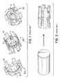
- a zoom lens holder 10a can be in the form of a raceway around the periphery of the lens (not shown) with a set of symmetrical protrusions or legs which are evenly spaced and extend proximally from the raceway in one direction which define the path of the lens during operation.
- a fixed lens holder 10b can be in the form of a raceway around the periphery of the lens with two sets of symmetrical protrusions or legs, with the first set of protrusions or legs extending proximally from the raceway in one direction, and the second set of protrusions or legs extending distally from the raceway in the opposite direction.
- Anhalt also discloses a simple lens holder 10c that does not contain any protrusions or legs extending from the raceway.
- the lens holders play an important role in the performance of the endoscopic video cameras, it is critical that the lens holders be manufactured with precision.
- the lens holders are manufactured from solid metal bar stocks by 100% machining, as illustrated in FIG. 2 .
- This manufacturing method unavoidably results in high manufacturing cost in terms of material used (and wasted) and the machining time. Using this manufacturing method, it is difficult, if not impossible, to machine the lens holders with consistent precision. Therefore, the traditional 100% machining is not suitable for a high volume production of the lens holders.
- MIM metal injection molding
- a metal powder is mixed with a binder to form a homogenous liquid mixture.
- the mixture is injected into a die or mold which is then subjected to high pressure to form a "green" metal blank, which typically is about 60% dense.
- the binder in the "green” metal blank is then burned off or removed chemically and the resulting skeleton, called “brown” metal blank, is sintered to near full density.
- the MIM process greatly saves the material used for manufacturing and allows a high volume production with reasonable consistency in quality.
- the MIM process is also versatile at producing small components having complex internal and external shapes.
- an improved manufacturing method for an endoscopic camera component such as a lens holder for an endoscope, which efficiently utilizes metal materials, minimizes secondary machining, shortens the overall manufacturing time, and increases consistency in the component quality. It is also desirable that such manufacturing method is sufficiently versatile to be applied to various types of lens holders and other similar types of metal components.
- the present invention provides a method of manufacturing an endoscope having at least one lens holder.
- the method comprises the steps of molding at least one brown metal blank by a metal injection molding (MIM) process, wherein the at least one brown metal blank has a sprue and a post, and is substantially similar in size and shape to the at least one lens holder, machining the at least one brown metal blank to form the at least one lens holder, installing a lens in each of the at least one lens holder, and assembling the at least one lens holder having the lens into an endoscopic tube to form an endoscope.
- MIM metal injection molding
- the step of machining comprises the steps of machining the inside dimensions of the at least one brown metal blank, and then machining the outside dimensions of the at least one brown metal blank using the inside machined surfaces as a reference to form the at least one lens holder.
- the inside surfaces as a reference, the final outside surfaces can be precisely grinded to the final dimensions with tight tolerances.
- the machining step may start with machining the outer surfaces of the brown metal blank, followed by machining the inside surfaces.
- the sprue and the post of the at least one brown metal blank are trimmed for ease of handling before machining the at least one brown metal blank. This is a further aspect of the present invention.
- the at least one brown metal blank contains an outer shell which supports and strengthens the at least one brown metal blank from damage during the molding and machining steps.
- machining the inside surfaces can be performed by holding the at least one brown metal blank from the outer shell.
- the outer shell also prevents deflecting the extrusions of the component during machining.
- lubricants are applied to the at least one lens holder using Dicronite coating process before a lens is installed in the at least one lens holder.
- the present invention also provides an endoscope having at least one lens holder which comprises a body containing a sintered feedstock, a machined inside surface, and a machined outside surface.
- the body of the at least one lens holder has a raceway and a set of extrusions extending from the periphery of said raceway in one direction.
- the body of the at least one lens holder has a raceway, a first set of extrusions extending from the periphery of said raceway in one direction, and a second set of extrusions extending from the periphery of said raceway in an opposite direction.
- FIG. 1 illustrates various types of lens holders as disclosed in U.S. Pat. Nos. 6,522,477 and 6,633,438, to Anhalt , a prior art.
- FIG. 2 illustrates the 100% machining method for manufacturing lens holders in accordance with another prior art.
- Fig. 3 illustrates various steps of the manufacturing method in accordance with one embodiment.
- FIG. 4 illustrates a number of zoom lens holders during various steps of the manufacturing method.
- FIG. 5 illustrates a zoom lens holder during various steps of the manufacturing method.
- FIG. 6 illustrates a fixed lens holder during various steps of the manufacturing method.
- the present invention provides a method of manufacturing an endoscope having one or more lens holders.
- endoscope and “endoscopic video camera” are used interchangeably in this Application.
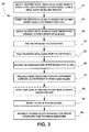
- FIG. 3 illustrates various steps of the manufacturing method 30 in accordance with the present invention.
- the first few of steps, 31 to 37, are devoted to the steps of manufacturing the lens holders which utilizes a near net machining concept.
- a metal blank also called MIM blank, which includes all molding features, e.g. gating, sprue, ejection pin marks, parting line, post, is first molded by a metal injection molding (MIM) process to a "near net shape" of the final component such that minimal secondary machining is required to complete the final component.
- MIM metal injection molding
- MIM process refers to the process which combines metal powders with binder materials to produce a 'feedstock' that is injected as a liquid into a hollow mold using plastic injection molding machines, followed by the binder removal and the sintering step to solidify the molded metal component.
- the MIM process is a superior process as compared to forging, casting, or other processes in that it allows an arbitrary selection of the shape of the metal body, including irregular shapes, and in that it is suitable for mass production at a lower cost, and in that the sintered product has excellent physical and mechanical properties as a result of the improved compaction obtained by use of fine powder.
- the MIM process can achieve tighter tolerance than other processes, e.g. casting, extrusion, or forging.
- the properties of the metal powders determine the final properties of the MIM product.
- Any metal or metal alloys capable of implementation within the MIM feedstock and responding to the magnet field created by external magnets can be used for fabricating the MIM blank for this invention.
- Suitable metal or metal alloys for the present invention include, but not limiting to, stainless steel, aluminum, nickel, brass, titanium, tantalum, iron, phosphor bronze, tungsten, gold, silver, copper, cobalt, chromium or alloys thereof.
- the preferred metal for the lens holders is magnetic stainless steel.
- near net shape means that the metal blank is substantially similar to the final component in terms of shapes and dimensions.
- the first step 31 is molding a "near net shape" green metal blank having a sprue, a post, and optionally an outer shell, using a metal injection molding process.
- the second step 32 is debinding the green metal blank to remove the polymer binder using a low temperature oven followed by step 33, sintering the green metal blank in high temperature furnace to fuse the metal powder together to form "near net shape" brown metal blank.
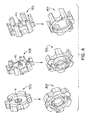
- FIGS. 4 to 6 illustrate different types of "near net shape" brown metal blanks having a sprue and a post during a manufacturing method in accordance with the present invention.
- FIG. 4 shows that a metal blank 40a,40b,40c which has an inner surface and an outer surface.
- the metal blank 40a,40b,40c has a center post 41,42,43 which is positioned in the center of the blank 40a,40b,40c and which forms an integrated part of the metal blank 40a,40b,40c.
- the metal blank 40a,40b,40c has a spruce (not shown) at the opposite end of the post 41,42,43.
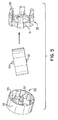
- FIGS. 5 and 6 show that a metal blank 50,60 which has an inner surface and an outer surface.
- the metal blank 50,60 has a center post 52,62 and a spruce 53,63 which locates at the opposite end of the center post 52,62. Both the center post 52,62 and a spruce 53,63 form an integrated part of the metal blank 50,60.
- the center post 41,42,43,52,62 provides support to the center material of the metal blank 40a,40b,40c,50,60 and prevents it from slumping during the sintering step.
- the center post 41,42,43,52,62 and sprue 53,63 provides an additional means for handling the metal blank 40a,40b,40c,50,60 during the manufacturing process. For instance, they are able to set the blank 40a,40b,40c,50,60 in the sintering fixture without having the blank surface in touch of the fixture surface to avoid the constraints of shrinkage at the blank surface during sintering because of the friction between the blank surface and the fixture surface.
- the center post 41,42,43,52,62 extends beyond the bottom surface of the metal blank 40a,40b,40c,50,60 to provide sufficient clearance between the bottom surface of the metal blank and the surface of the sintering fixture.
- the metal blank 50,60 may optionally comprise an outer shell 54,64, which forms an integrated part of the metal blank 50,60.
- the outer shell 54,64 has an interior surface and an exterior surface.
- the interior surface of the outer shell 54,64 is in contact with the outer surface of the metal blank 50,60, and particularly, partial or all peripheries of the extrusions/legs 55,65,65' and the raceway 51,61 of the metal blank 50,60.
- the outer shell 54,64 substantially covers the rest parts of metal blank 50,60.
- the outer shell 54,64 provides advantageous structure support to the metal blank 50,60 during the sintering and machining steps.
- the outer shell prevents deflecting any extrusion of the component.
- the outer shell is beneficial when the lens holder has long extrusions/legs, e.g. the zoom lens holder in FIG. 5 and the fixed lens holder in FIG. 6 .
- the outer shell is not necessary, e.g. the various lens holders in FIG. 4 .
- the thickness of the outer shell 54,64 may vary, but necessarily depends on the type of metal used and the extent of secondary machining.
- the outer shell 54,64 should be sufficiently strong to stand the impacts from the secondary machining.
- the next step 34 is optional for the manufacturing method in accordance with the present invention.
- the sprue 53,63 and the post 52,62 are trimmed for ease of handling.
- the manufacturing method may optionally have the step 35 in which the metal blank 50,60 is held from the outer shell 54,64 for ease of handling, for example, during the step of machining the inside surface of the metal blank 50,60.
- steps 34 and 35 can be performed in reversed order.
- the metal blank 40a,40b,40c,50,60 is post machined to the required specifications of the lens holder 40d,40e,40f,56,66.
- machining or “machined” refers to the conventional metalworking processes such as heat treatments and/or surface treatments such as abrading, cutting, drilling, forming, grinding, and/or shaping of a piece of metal into the desired final piece using by machine tools such as lathes, power saws, and presses.
- the center post, and the outer shell if any, may be removed during the secondary machining or at the end of the machining, depending on the geometry of the component and the need to access to certain parts of the component.
- the metal blank 40a,40b,40c,50,60 is "near net shape" of the lens holder 40d,40e,40f,56,66, minimal machining is required to form the desired lens holder. Less machining means less machining time and lower manufacturing cost.
- the present method avoids material waste, saves machining time, and improves the quality consistency of the finished lens holders.
- the machining steps 36,37 are typically performed by the step of machining the inside dimensions of the metal blank 36, followed by the step of machining the outside dimensions of the metal blank using the inside machined surfaces of the metal blank 37.
- the inside surfaces By using the inside surfaces as a reference, the final outside surface can be precisely grinded to the final dimensions with tight tolerances which cannot be achieved by a direct molding process.
- Conventional Computer Numerical Controlled (CNC) milling is unable to accomplish the outside diameter as the interrupt cutting action will deflect any extrusions of the metal blank during the operation and affect the final dimensions.
- machining steps can be performed in a less preferred order, for instance, by the step of machining the outer surfaces of the metal blank first 37, followed by the step of machining the inner surfaces 36, and optionally using the outer surfaces as a reference, to form the lens holder.
- lubricants are applied to the lens holder using Dicronite coating process, step 38.
- a lens is installed in the lens holder, the step 39.
- the lens holder installed with the lens is assembled into an endoscopic tube to form an endoscope, the step 40.
- each lens holder can be manufactured in accordance with same or different embodiments of the present invention. Additionally, more than one lens may be installed in a lens holder and different type of lenses can be installed in the same or different lens holders.
- the present invention also provides an endoscope having one or more lens holders, wherein the lens holder comprises a body which in turn comprises a sintered feedstock, a machined inside surface, and a machined outside surface.
- the feedstock is preferably made by stainless steel.
- the lens holders of the present invention distinguish from the prior art lens holders in that the body of the lens holders of the present invention contains a sintered feedstock, whereas the body of the prior art lens holders is made up by 100% metal stock. Because the sintered feedstock has gone through a high temperature treatment during the sintering step in the MIM process, the properties of two bodies are different from each other. For instance, the sintered feedstock usually has a higher density and durability than that of the metal stock.
- a lens holder 40e,40f,56 has a raceway 45,46,51 with a set of symmetrical extrusions/legs 47,48,55 which are evenly spaced and extend from the raceway 45,46,51 in one direction.
- a lens holder 66 has a raceway 61 with two sets of symmetrical extrusions/legs 65,65' with the first set of extrusions/legs 65 extending proximally from raceway 61 in one direction, and the second set of extrusions/legs 65' extending distally from raceway 61 in the opposite direction.
- a simple lens holder 40d has no protrusions extending from the raceway 44. All these lens holders share two common structure features. First, their exterior shape, defined by the periphery of the raceway 44,45,46,51,61 and /or the extrusions/legs 447,48,55,65,65' is generally of cylinder shape, such that an outer shell of sleeve shape is able to cover the lens holders during the manufacturing steps. Second, they have a lengthwise hollow center for holding a lens.
- Method of manufacturing an endoscope having at least one lens holder comprising the steps of: forming at least one green metal blank using metal injection molding, said at least one green metal blank comprising a sprue, a post and a outer shell, said at least one green metal blank having inside dimensions and outer dimensions, and said at least one green metal blank substantially similar in size and shape to said at least one lens holder; debinding said at least green metal blank to remove polymer binders using a low temperature oven to form at least one debinded green metal blank; sintering said at least one debinded green metal blank in a high temperature furnace to form at least one brown metal blank; machining said at least one brown metal blank to form said at least one lens holder; installing a lens in each of said at least one lens holder; and assembling said at least one lens holder installed with said lens into said endoscope.
- Method of manufacturing an endoscope having at least one lens holder according to clause 3, wherein said step of machining said at least one brown metal blank to form said at least one lens holder comprises the steps of: holding said at least one brown metal blank from said outer shell and machining said inside dimensions of said at least one brown metal blank; and machining said outside dimensions of said at least one brown metal blank using said inside dimensions of said at least one brown metal blank as a reference to form said at least one lens holder.
- Method of manufacturing an endoscope having at least one lens holder according to clause 1, wherein said step of machining said at least one brown metal blank to form said at least one lens holder comprises the steps of: machining said outside dimensions of said at least one brown metal blank; and machining said inside dimensions said at least one brown metal blank using said outside dimensions of said at least one brown metal blank as a reference to form said at least one lens holder.
- Method of manufacturing an endoscope having at least one lens holder comprising the steps of: molding at least one brown metal blank using a metal injection molding process, said at least one brown metal blank comprising a sprue and a post, said at least one brown metal blank having inside dimensions and outer dimensions, and said at least one brown metal blank substantially similar in size and shape to said at least one lens holder; machining said at least one brown metal blank to form said at least one lens holder; installing a lens in each of said at least one lens holder; and assembling said at least one lens holder installed with said lens into said endoscope.
- Method of manufacturing an endoscope having at least one lens holder according to clause 10, wherein the step of machining said at least one brown metal blank to form said at least one lens holder comprises the steps of: machining said inside dimensions of said at least one brown metal blank; and machining said outside dimensions of said at least one brown metal blank using said inside dimensions of said at least one brown metal blank as a reference to form said at least one lens holder.
- Method of manufacturing an endoscope having at least one lens holder according to clause 11, wherein said step of machining said at least one brown metal blank to form said at least one lens holder comprises the steps of: machining said inside dimensions of said at least one brown metal blank; and machining said outside dimensions of said at least one brown metal blank using said inside dimensions of said at least one brown metal blank as a reference to form said at least one lens holder.
- Method of manufacturing an endoscope having at least one lens holder according to clause 10, wherein sais step of machining said at least one brown metal blank to form said at least one lens holder comprises the steps of: machining said outside dimensions of said at least one brown metal blank; and machining said inside dimensions said at least one brown metal blank using said outside dimensions said at least one brown metal blank as a reference to form said at least one lens holder.
- Endoscope comprising at least one lens holder, said at least one lens holder comprising: a body comprising a sintered feedstock; a machined inside surface; and a machined outside surface.
Abstract
Description
- The present invention is generally related to a method of manufacturing endoscopic camera components and, more particularly, to a method of manufacturing lens holders for use in endoscopic cameras.
- Endoscopes and endoscopic video cameras are now widely used by physicians during surgery to view inside body cavities. In an endoscopic surgical procedure, small incisions, called portals, are made in a patient. An endoscope or endoscopic video camera is inserted in one of the portals. Surgical instruments used to perform specific surgical tasks are inserted into other portals. The surgeon views the surgical site through the endoscope or endoscopic video camera to determine how to manipulate the surgical instruments in order to accomplish the surgical procedure. An advantage of performing endoscopic surgery is that, since the portions of the body that are cut open are minimized, the portions of the body that need to heal after surgery are likewise reduced. Moreover, during an endoscopic surgical procedure, only relatively small portions of the patient's internal organs and tissues are exposed to the open environment. This minimal opening of the patient's body lessens the extent to which a patient's organs and tissues are open to infection.
- Typically, an endoscopic video camera contains an optical focusing lens and a focusing device that can be adjusted to optimize images transmitted by the endoscopic video camera. The focusing device usually utilizes magnetic drives to move or rotate the focusing lens axially within the lens holder. As such, the lens holder is a small yet convoluted part of the endoscopic video camera. For example, the endoscopic video cameras described in
U.S. Pat. No. 5,359,992 issued to Hori et al. , andU.S. Pat. No. 5,056,902 issued to Chinnock et al. require the lens holders adapted to the mechanical linkages between the internal magnets and the lens, and the movement of the lens within the interior chamber in response to the rotation of external magnets located around the periphery of the interior chamber; and the endoscopic video cameras described inU.S. Pat. No. 5,978,161 issued to Lemke ,U.S. Pat. No. 5,835,865 issued to Speier et al. , andU.S. Pat. No. 5,706,143 issued to Hipp require lens holders having helical grooves, magnet seats and mechanical linkages to connect the internal magnets to the lens, or require the internal magnet to travel within a helical channel in order to convert the rotational movement of the internal magnets to linear movement of the lens. - In an effort to simplify the magnetic focusing device and to solve various shortcomings associated with the complicated endoscopic video cameras,
U.S. Pat. Nos. 6,522,477 and6,633,438, both issued to Anhalt , disclose endoscopic video cameras which do not require a mechanical linkage between the lens and internal magnets. The lens holders in Anhalt have the following structures, as illustrated inFIG. 1 . A zoom lens holder 10a can be in the form of a raceway around the periphery of the lens (not shown) with a set of symmetrical protrusions or legs which are evenly spaced and extend proximally from the raceway in one direction which define the path of the lens during operation. A fixed lens holder 10b can be in the form of a raceway around the periphery of the lens with two sets of symmetrical protrusions or legs, with the first set of protrusions or legs extending proximally from the raceway in one direction, and the second set of protrusions or legs extending distally from the raceway in the opposite direction. Anhalt also discloses asimple lens holder 10c that does not contain any protrusions or legs extending from the raceway. - Because the lens holders play an important role in the performance of the endoscopic video cameras, it is critical that the lens holders be manufactured with precision.
- Traditionally, the lens holders are manufactured from solid metal bar stocks by 100% machining, as illustrated in
FIG. 2 . This manufacturing method unavoidably results in high manufacturing cost in terms of material used (and wasted) and the machining time. Using this manufacturing method, it is difficult, if not impossible, to machine the lens holders with consistent precision. Therefore, the traditional 100% machining is not suitable for a high volume production of the lens holders. - In recent years, metal injection molding ("MIM") processes have been used to manufacture various components in medical or optical instruments, as disclosed in
U.S. Pat. Nos. 7,762,960 ,6,514,269 ,7,706,065 and7,686,449 ; andU.S. Pat. Appln. No. 20060242813 . The teachings of these patents are incorporated herein by references in its entirety. - In a typical MIM process, a metal powder is mixed with a binder to form a homogenous liquid mixture. The mixture is injected into a die or mold which is then subjected to high pressure to form a "green" metal blank, which typically is about 60% dense. The binder in the "green" metal blank is then burned off or removed chemically and the resulting skeleton, called "brown" metal blank, is sintered to near full density. Compared to the traditional 100% machining and other deposition techniques such as casting, stamping, and lithography, the MIM process greatly saves the material used for manufacturing and allows a high volume production with reasonable consistency in quality. The MIM process is also versatile at producing small components having complex internal and external shapes.
- One long and continuing problem encountered with the MIM process is the shrinkage of metal blanks from the "green" stage. The shrinkage problem is generally more obvious in complex metal blanks, due to uneven shrinkages of the interior and exterior configurations after sintering. Another problem of the MIM process is that sintered metal blanks usually require a great extent of metal conditioning treatment in order to arrive at the desired dimensions of the final components. The metal conditioning treatment to sintered metal blanks is often referred as "secondary machining" or "post machining." As with all machining, more secondary machining means more machining time and higher manufacturing cost.
- To overcome the shrinkage problem encountered by typical the MIM process,
U.S. Pat. No. 6,508,980 to Sachs, et al. ("Sachs") provides a two-material sintering method. In contrast to a conventional method where a binder is removed and the powder particles themselves sintered together to provide a shrunken final component, in Sachs the material that joins the powder particles is provided as an independent material and there is no movement of the powder particles after they have been placed during sintering. Although the skeleton shrinkage may be avoided, the method in Sachs requires two different metal materials and the repeated steps of adding the second independent material into the matrix of the first material and binding the first and second materials. - What is desired, therefore, is an improved manufacturing method for an endoscopic camera component, such as a lens holder for an endoscope, which efficiently utilizes metal materials, minimizes secondary machining, shortens the overall manufacturing time, and increases consistency in the component quality. It is also desirable that such manufacturing method is sufficiently versatile to be applied to various types of lens holders and other similar types of metal components.
- The present invention provides a method of manufacturing an endoscope having at least one lens holder. The method comprises the steps of molding at least one brown metal blank by a metal injection molding (MIM) process, wherein the at least one brown metal blank has a sprue and a post, and is substantially similar in size and shape to the at least one lens holder, machining the at least one brown metal blank to form the at least one lens holder, installing a lens in each of the at least one lens holder, and assembling the at least one lens holder having the lens into an endoscopic tube to form an endoscope. One aspect of the invention is that minimal machining is required to form the at least one lens holder because the at least one brown metal blank is substantially similar in size and shape to the at least one lens holder. By using the MIM process, the present invention also achieves higher material utilization and increased quality control of the finished components, e.g. the lens holders.
- In a preferred embodiment, the step of machining comprises the steps of machining the inside dimensions of the at least one brown metal blank, and then machining the outside dimensions of the at least one brown metal blank using the inside machined surfaces as a reference to form the at least one lens holder. By using the inside surfaces as a reference, the final outside surfaces can be precisely grinded to the final dimensions with tight tolerances. This is another aspect of the present invention.
- In a less preferred embodiment, the machining step may start with machining the outer surfaces of the brown metal blank, followed by machining the inside surfaces.
- In one embodiment, the sprue and the post of the at least one brown metal blank are trimmed for ease of handling before machining the at least one brown metal blank. This is a further aspect of the present invention.
- In another embodiment, the at least one brown metal blank contains an outer shell which supports and strengthens the at least one brown metal blank from damage during the molding and machining steps. In this embodiment, machining the inside surfaces can be performed by holding the at least one brown metal blank from the outer shell. The outer shell also prevents deflecting the extrusions of the component during machining. This is yet another aspect of the present invention.
- In another embodiment, lubricants are applied to the at least one lens holder using Dicronite coating process before a lens is installed in the at least one lens holder.
- The present invention also provides an endoscope having at least one lens holder which comprises a body containing a sintered feedstock, a machined inside surface, and a machined outside surface.
- In one embodiment, the body of the at least one lens holder has a raceway and a set of extrusions extending from the periphery of said raceway in one direction.
- In another embodiment, the body of the at least one lens holder has a raceway, a first set of extrusions extending from the periphery of said raceway in one direction, and a second set of extrusions extending from the periphery of said raceway in an opposite direction.
-
FIG. 1 illustrates various types of lens holders as disclosed inU.S. Pat. Nos. 6,522,477 and6,633,438, to Anhalt , a prior art. -
FIG. 2 illustrates the 100% machining method for manufacturing lens holders in accordance with another prior art. -
Fig. 3 illustrates various steps of the manufacturing method in accordance with one embodiment. -
FIG. 4 illustrates a number of zoom lens holders during various steps of the manufacturing method. -
FIG. 5 illustrates a zoom lens holder during various steps of the manufacturing method. -
FIG. 6 illustrates a fixed lens holder during various steps of the manufacturing method. - The present invention provides a method of manufacturing an endoscope having one or more lens holders. The terms "endoscope" and "endoscopic video camera" are used interchangeably in this Application.
-
FIG. 3 illustrates various steps of themanufacturing method 30 in accordance with the present invention. The first few of steps, 31 to 37, are devoted to the steps of manufacturing the lens holders which utilizes a near net machining concept. Under this concept, a metal blank, also called MIM blank, which includes all molding features, e.g. gating, sprue, ejection pin marks, parting line, post, is first molded by a metal injection molding (MIM) process to a "near net shape" of the final component such that minimal secondary machining is required to complete the final component. - The term "MIM process" refers to the process which combines metal powders with binder materials to produce a 'feedstock' that is injected as a liquid into a hollow mold using plastic injection molding machines, followed by the binder removal and the sintering step to solidify the molded metal component. The MIM process is a superior process as compared to forging, casting, or other processes in that it allows an arbitrary selection of the shape of the metal body, including irregular shapes, and in that it is suitable for mass production at a lower cost, and in that the sintered product has excellent physical and mechanical properties as a result of the improved compaction obtained by use of fine powder. In addition, the MIM process can achieve tighter tolerance than other processes, e.g. casting, extrusion, or forging. The MIM process and the feedstock for use therein have been described, for example, in
U.S. Pat. Nos. 4,694,881 ,4,694,882 ,5,040,589 ,5,064,463 ,5,577,546 ,5,848,350 ,6,860,316 ,6,890,368 ,6,838,046 ,6,790,252 ,6,669,898 ,6,619,370 ,6,478,842 ,6,470,956 ,6,350,328 ,6,298,901 ,5,993,507 ,5,989,493 , andU.S. Pat. Appln. No. 20060242813 , the disclosures of each of which are incorporated herein in their entirety. - The properties of the metal powders determine the final properties of the MIM product. Any metal or metal alloys capable of implementation within the MIM feedstock and responding to the magnet field created by external magnets can be used for fabricating the MIM blank for this invention. Suitable metal or metal alloys for the present invention include, but not limiting to, stainless steel, aluminum, nickel, brass, titanium, tantalum, iron, phosphor bronze, tungsten, gold, silver, copper, cobalt, chromium or alloys thereof. The preferred metal for the lens holders is magnetic stainless steel.
- The term "near net shape" means that the metal blank is substantially similar to the final component in terms of shapes and dimensions.
- The
first step 31 is molding a "near net shape" green metal blank having a sprue, a post, and optionally an outer shell, using a metal injection molding process. - The
second step 32 is debinding the green metal blank to remove the polymer binder using a low temperature oven followed bystep 33, sintering the green metal blank in high temperature furnace to fuse the metal powder together to form "near net shape" brown metal blank. -
FIGS. 4 to 6 illustrate different types of "near net shape" brown metal blanks having a sprue and a post during a manufacturing method in accordance with the present invention. -
FIG. 4 shows that a metal blank 40a,40b,40c which has an inner surface and an outer surface. The metal blank 40a,40b,40c has acenter post post -
FIGS. 5 and6 show that ametal blank metal blank center post spruce center post center post spruce metal blank - The
center post center post sprue center post - The
metal blank outer shell metal blank FIGS. 5 and6 , theouter shell outer shell metal blank legs raceway metal blank outer shell outer shell metal blank legs metal blank FIG. 5 and the fixed lens holder inFIG. 6 . When the metal blank has no or relatively short extrusions/legs, the outer shell is not necessary, e.g. the various lens holders inFIG. 4 . - The thickness of the
outer shell outer shell - The
next step 34 is optional for the manufacturing method in accordance with the present invention. In thisstep 34, thesprue post - If the
metal blank outer shell step 35 in which themetal blank outer shell metal blank - A person with ordinary skilled in the art would understand that
steps - During the
next steps lens holder lens holder - Comparing to the prior art in which the lens holder is manufactured by 100% machining from a solid bar stock, the present method avoids material waste, saves machining time, and improves the quality consistency of the finished lens holders.
- The machining steps 36,37 are typically performed by the step of machining the inside dimensions of the
metal blank 36, followed by the step of machining the outside dimensions of the metal blank using the inside machined surfaces of themetal blank 37. By using the inside surfaces as a reference, the final outside surface can be precisely grinded to the final dimensions with tight tolerances which cannot be achieved by a direct molding process. Conventional Computer Numerical Controlled (CNC) milling is unable to accomplish the outside diameter as the interrupt cutting action will deflect any extrusions of the metal blank during the operation and affect the final dimensions. - A person skilled in the art would understand that the machining steps can be performed in a less preferred order, for instance, by the step of machining the outer surfaces of the metal blank first 37, followed by the step of machining the
inner surfaces 36, and optionally using the outer surfaces as a reference, to form the lens holder. - Optionally, lubricants are applied to the lens holder using Dicronite coating process, step 38. After that, a lens is installed in the lens holder, the
step 39. Then the lens holder installed with the lens is assembled into an endoscopic tube to form an endoscope, thestep 40. - A person with ordinary skill in the art would understand that, in the event that an endoscope contains more than one lens holder, each lens holder can be manufactured in accordance with same or different embodiments of the present invention. Additionally, more than one lens may be installed in a lens holder and different type of lenses can be installed in the same or different lens holders.
- The present invention also provides an endoscope having one or more lens holders, wherein the lens holder comprises a body which in turn comprises a sintered feedstock, a machined inside surface, and a machined outside surface. The feedstock is preferably made by stainless steel.
- The lens holders of the present invention distinguish from the prior art lens holders in that the body of the lens holders of the present invention contains a sintered feedstock, whereas the body of the prior art lens holders is made up by 100% metal stock. Because the sintered feedstock has gone through a high temperature treatment during the sintering step in the MIM process, the properties of two bodies are different from each other. For instance, the sintered feedstock usually has a higher density and durability than that of the metal stock.
- The body of the lens holders may have various shapes and dimensions as illustrated in
FIGS. 4 to 6 . In one embodiment, alens holder raceway 45,46,51 with a set of symmetrical extrusions/legs 47,48,55 which are evenly spaced and extend from theraceway 45,46,51 in one direction. In another embodiment, alens holder 66 has araceway 61 with two sets of symmetrical extrusions/legs 65,65' with the first set of extrusions/legs 65 extending proximally fromraceway 61 in one direction, and the second set of extrusions/legs 65' extending distally fromraceway 61 in the opposite direction. In yet another embodiment, asimple lens holder 40d has no protrusions extending from the raceway 44. All these lens holders share two common structure features. First, their exterior shape, defined by the periphery of theraceway legs - The present application discloses in particular the aspects defined in the following clauses which form part of the present description, but are not claims in accordance with
decision J 15/88 of the Legal Board of Appeal of the European Patent Office. - (1) Method of manufacturing an endoscope having at least one lens holder comprising the steps of: forming at least one green metal blank using metal injection molding, said at least one green metal blank comprising a sprue, a post and a outer shell, said at least one green metal blank having inside dimensions and outer dimensions, and said at least one green metal blank substantially similar in size and shape to said at least one lens holder; debinding said at least green metal blank to remove polymer binders using a low temperature oven to form at least one debinded green metal blank; sintering said at least one debinded green metal blank in a high temperature furnace to form at least one brown metal blank; machining said at least one brown metal blank to form said at least one lens holder; installing a lens in each of said at least one lens holder; and assembling said at least one lens holder installed with said lens into said endoscope.
- (2) Method of manufacturing an endoscope having at least one lens holder according to clause 1, wherein the step of machining said at least one brown metal blank to form said at least one lens holder comprises the steps of: holding said at least one brown metal blank from said outer shell and machining said inside dimensions of said at least one brown metal blank; and machining said outside dimensions of said at least one brown metal blank using said inside dimensions of said at least one brown metal blank as a reference to form said at least one lens holder.
- (3) Method of manufacturing an endoscope having at least one lens holder according to clause 1, further comprising before said step of machining said at least one brown metal blank, the step of trimming said sprue and said post of said at least one brown metal blank.
- (4) Method of manufacturing an endoscope having at least one lens holder according to clause 3, wherein said step of machining said at least one brown metal blank to form said at least one lens holder comprises the steps of: holding said at least one brown metal blank from said outer shell and machining said inside dimensions of said at least one brown metal blank; and machining said outside dimensions of said at least one brown metal blank using said inside dimensions of said at least one brown metal blank as a reference to form said at least one lens holder.
- (5) Method of manufacturing an endoscope having at least one lens holder according to clause 1, further comprising before said step of installing said lens in said at least one lens holder, the step of applying lubricants to said lens holder using Dicronite coating process.
- (6) Method of manufacturing an endoscope having at least one lens holder according to clause 1, wherein said step of machining said at least one brown metal blank to form said at least one lens holder comprises the steps of: machining said outside dimensions of said at least one brown metal blank; and machining said inside dimensions said at least one brown metal blank using said outside dimensions of said at least one brown metal blank as a reference to form said at least one lens holder.
- (7) Method of manufacturing an endoscope having at least one lens holder according to clause 1, wherein said at least one brown metal blank is made of stainless steel.
- (8) Method of manufacturing an endoscope having at least one lens holder according to clause 1, wherein said at least one lens holder has a raceway and a set of extrusions extending from the periphery of said raceway in one direction.
- (9) Method of manufacturing an endoscope having at least one lens holder according to clause 1, wherein said at least one lens holder has a raceway, a first set of extrusions extending from the periphery of said raceway in one direction, and a second set of extrusions extending from the periphery of said raceway in an opposite direction.
- (10) Method of manufacturing an endoscope having at least one lens holder comprising the steps of: molding at least one brown metal blank using a metal injection molding process, said at least one brown metal blank comprising a sprue and a post, said at least one brown metal blank having inside dimensions and outer dimensions, and said at least one brown metal blank substantially similar in size and shape to said at least one lens holder; machining said at least one brown metal blank to form said at least one lens holder; installing a lens in each of said at least one lens holder; and assembling said at least one lens holder installed with said lens into said endoscope.
- (11) Method of manufacturing an endoscope having at least one lens holder according to clause 10, wherein the step of machining said at least one brown metal blank to form said at least one lens holder comprises the steps of: machining said inside dimensions of said at least one brown metal blank; and machining said outside dimensions of said at least one brown metal blank using said inside dimensions of said at least one brown metal blank as a reference to form said at least one lens holder.
- (12) Method of manufacturing an endoscope having at least one lens holder according to clause 10, further comprising before said step of machining said at least one brown metal blank, the step of trimming said sprue and said post of said at least one brown metal blank.
- (13) Method of manufacturing an endoscope having at least one lens holder according to clause 11, wherein said step of machining said at least one brown metal blank to form said at least one lens holder comprises the steps of: machining said inside dimensions of said at least one brown metal blank; and machining said outside dimensions of said at least one brown metal blank using said inside dimensions of said at least one brown metal blank as a reference to form said at least one lens holder.
- (14) Method of manufacturing an endoscope having at least one lens holder according to clause 10, further comprising before said step of installing said lens in said at least one lens holder, the step of applying lubricants to said lens holder using Dicronite coating process.
- (15) Method of manufacturing an endoscope having at least one lens holder according to clause 10, wherein sais step of machining said at least one brown metal blank to form said at least one lens holder comprises the steps of: machining said outside dimensions of said at least one brown metal blank; and machining said inside dimensions said at least one brown metal blank using said outside dimensions said at least one brown metal blank as a reference to form said at least one lens holder.
- (16) Method of manufacturing an endoscope having at least one lens holder according to clause 10, wherein said at least one brown metal blank is made of stainless steel.
- (17) Method of manufacturing an endoscope having at least one lens holder according to clause 10, wherein said at least one lens holder has a raceway and a set of extrusions extending from the periphery of said raceway in one direction.
- (18) Method of manufacturing an endoscope having at least one lens holder according to clause 10, wherein said at least one lens holder has a raceway, a first set of extrusions extending from the periphery of said raceway in one direction, and a second set of extrusions extending from the periphery of said raceway in an opposite direction.
- (19) Method of manufacturing an endoscope having at least one lens holder according to clause 10, wherein said post extends beyond the bottom surface of said at least one brown metal blank to provide clearance between said bottom surface of said at least one brown metal blank and the surface of the sintering fixture.
- (20) Endoscope comprising at least one lens holder, said at least one lens holder comprising: a body comprising a sintered feedstock; a machined inside surface; and a machined outside surface.
- (21) Endoscope according to clause 20, wherein said sintered feedstock is made of stainless steel.
- (22) Endoscope according to clause 20, wherein said body has a raceway and a set of extrusions extending from the periphery of said raceway in one direction.
- (23) Endoscope according to clause 20, wherein said body has a raceway, a first set of extrusions extending from the periphery of said raceway in one direction, and a second set of extrusions extending from the periphery of said raceway in an opposite direction.
- The foregoing detailed description is provided to describe the invention in detail, and is not intended to limit the invention. Those skilled in the art will appreciate that various modifications may be made to the invention without departing significantly from the spirit and scope thereof.
Claims (14)
- Method of manufacturing an endoscope having at least one lens holder comprising the steps of:molding at least one brown metal blank using a metal injection molding process, said at least one brown metal blank comprising a sprue and a post, said at least one brown metal blank having inside dimensions and outer dimensions, and said at least one brown metal blank substantially similar in size and shape to said at least one lens holder;machining said at least one brown metal blank to form said at least one lens holder;installing a lens in each of said at least one lens holder; andassembling said at least one lens holder installed with said lens into said endoscope.
- Method according to claim 1, the step of molding at least one brown metal blank comprising the steps of:forming at least one green metal blank using metal injection molding, said at least one green metal blank comprising a sprue, a post and a outer shell, said at least one green metal blank having inside dimensions and outer dimensions, and said at least one green metal blank substantially similar in size and shape to said at least one lens holder;debinding said at least green metal blank to remove polymer binders using a low temperature oven to form at least one debinded green metal blank;sintering said at least one debinded green metal blank in a high temperature furnace to form said at least one brown metal blank.
- Method according to any preceding claim, further comprising before said step of machining said at least one brown metal blank, the step of trimming said sprue and said post of said at least one brown metal blank.
- Method according to any preceding claim, wherein said step of machining said at least one brown metal blank to form said at least one lens holder comprises the steps of:machining said inside dimensions of said at least one brown metal blank; andmachining said outside dimensions of said at least one brown metal blank using said inside dimensions of said at least one brown metal blank as a reference to form said at least one lens holder.
- Method according to any preceding claim, further comprising before said step of installing said lens in said at least one lens holder, the step of applying lubricants to said lens holder using Dicronite coating process.
- Method according to any preceding claim, wherein said step of machining said at least one brown metal blank to form said at least one lens holder comprises the steps of:machining said outside dimensions of said at least one brown metal blank; andmachining said inside dimensions said at least one brown metal blank using said outside dimensions of said at least one brown metal blank as a reference to form said at least one lens holder.
- Method according to any preceding claim, wherein said at least one brown metal blank is made of stainless steel.
- Method according to any preceding claim, wherein said at least one lens holder has a raceway and a set of extrusions extending from the periphery of said raceway in one direction.
- Method according to any preceding claim, wherein said at least one lens holder has a raceway, a first set of extrusions extending from the periphery of said raceway in one direction, and a second set of extrusions extending from the periphery of said raceway in an opposite direction.
- Method according to any preceding claim, wherein said post extends beyond the bottom surface of said at least one brown metal blank to provide clearance between said bottom surface of said at least one brown metal blank and the surface of the sintering fixture.
- Endoscope comprising at least one lens holder, said at least one lens holder comprising:a body comprising a sintered feedstock;a machined inside surface; anda machined outside surface.
- Endoscope according to claim 11, wherein said sintered feedstock is made of stainless steel.
- Endoscope according to any of claims 11-12, wherein said body has a raceway and a set of extrusions extending from the periphery of said raceway in one direction.
- Endoscope according to any of claims 11-12, wherein said body has a raceway, a first set of extrusions extending from the periphery of said raceway in one direction, and a second set of extrusions extending from the periphery of said raceway in an opposite direction.
Applications Claiming Priority (1)
| Application Number | Priority Date | Filing Date | Title |
|---|---|---|---|
| US13/178,321 US8916090B2 (en) | 2011-07-07 | 2011-07-07 | Endoscopic camera component manufacturing method |
Publications (3)
| Publication Number | Publication Date |
|---|---|
| EP2543458A2 true EP2543458A2 (en) | 2013-01-09 |
| EP2543458A3 EP2543458A3 (en) | 2013-11-20 |
| EP2543458B1 EP2543458B1 (en) | 2017-03-22 |
Family
ID=46466300
Family Applications (1)
| Application Number | Title | Priority Date | Filing Date |
|---|---|---|---|
| EP12175584.7A Active EP2543458B1 (en) | 2011-07-07 | 2012-07-09 | Endoscopic camera component manufacturing method |
Country Status (4)
| Country | Link |
|---|---|
| US (2) | US8916090B2 (en) |
| EP (1) | EP2543458B1 (en) |
| JP (1) | JP2013017814A (en) |
| CA (1) | CA2779970C (en) |
Cited By (4)
| Publication number | Priority date | Publication date | Assignee | Title |
|---|---|---|---|---|
| EP2977128A1 (en) * | 2014-07-21 | 2016-01-27 | Pratt & Whitney Canada Corp. | Method of forming green part and manufacturing method using same |
| EP2979784A1 (en) * | 2014-08-02 | 2016-02-03 | Gerd Axel Walther | Workpiece blank and method for manufacturing a workpiece with a volume changing process |
| CN108161367A (en) * | 2018-01-17 | 2018-06-15 | 昆山腾荣机械有限公司 | A kind of new-energy automobile light durable motor casing manufacturing process |
| CN111299590A (en) * | 2020-04-14 | 2020-06-19 | 东莞市金材五金有限公司 | Preparation method of MIM 316L stainless steel highlight watch case |
Families Citing this family (2)
| Publication number | Priority date | Publication date | Assignee | Title |
|---|---|---|---|---|
| US9526403B2 (en) | 2015-02-04 | 2016-12-27 | Karl Storz Imaging, Inc. | Polymeric material for use in and with sterilizable medical devices |
| CN112330085A (en) * | 2020-09-17 | 2021-02-05 | 上海微亿智造科技有限公司 | Quality control method and system for MIM metal injection molding sintered product |
Citations (28)
| Publication number | Priority date | Publication date | Assignee | Title |
|---|---|---|---|---|
| US4694882A (en) | 1981-12-01 | 1987-09-22 | The Dow Chemical Company | Method for making thixotropic materials |
| US4694881A (en) | 1981-12-01 | 1987-09-22 | The Dow Chemical Company | Method for making thixotropic materials |
| US5040589A (en) | 1989-02-10 | 1991-08-20 | The Dow Chemical Company | Method and apparatus for the injection molding of metal alloys |
| US5056902A (en) | 1990-04-25 | 1991-10-15 | Smith & Nephew Dyonics, Inc. | Magnetically coupled lens actuator |
| US5064463A (en) | 1991-01-14 | 1991-11-12 | Ciomek Michael A | Feedstock and process for metal injection molding |
| US5359992A (en) | 1992-10-20 | 1994-11-01 | Linvatec Corporation | Endoscope coupler with magnetic focus control |
| US5577546A (en) | 1992-09-11 | 1996-11-26 | Comalco Aluminium Limited | Particulate feedstock for metal injection molding |
| US5706143A (en) | 1995-06-14 | 1998-01-06 | Richard Wolf Gmbh | Optical device |
| US5835865A (en) | 1994-07-04 | 1998-11-10 | Siemens Aktiengesellschaft | Method and device for the disposal of a cation exchanger |
| US5848350A (en) | 1997-10-31 | 1998-12-08 | Flomet, Inc. | Nickel-free stainless steel alloy processible through metal injection molding techniques to produce articles intended for use in contact with the human body |
| US5978161A (en) | 1996-05-23 | 1999-11-02 | Norbert Lemke | Magnetic device for focusing an optical imaging system |
| US5989493A (en) | 1998-08-28 | 1999-11-23 | Alliedsignal Inc. | Net shape hastelloy X made by metal injection molding using an aqueous binder |
| US5993507A (en) | 1997-12-29 | 1999-11-30 | Remington Arms Co., Inc. | Composition and process for metal injection molding |
| US6298901B1 (en) | 1998-07-03 | 2001-10-09 | Mazda Motor Corporation | Method and apparatus for semi-molten metal injection molding |
| US6350328B1 (en) | 2000-06-27 | 2002-02-26 | Rossborough Manufacturing Co. Lp | Metal injection molding |
| US6478842B1 (en) | 2000-07-19 | 2002-11-12 | R. A. Brands, Llc | Preparation of articles using metal injection molding |
| US6508980B1 (en) | 1997-09-26 | 2003-01-21 | Massachusetts Institute Of Technology | Metal and ceramic containing parts produced from powder using binders derived from salt |
| US6514269B2 (en) | 2000-06-13 | 2003-02-04 | Olympus Optical Co., Ltd. | Endoscopic treating instrument |
| US6522477B2 (en) | 2001-04-17 | 2003-02-18 | Karl Storz Imaging, Inc. | Endoscopic video camera with magnetic drive focusing |
| US6619370B2 (en) | 1998-07-03 | 2003-09-16 | Mazda Motor Corporation | Method and apparatus for semi-molten metal injection molding |
| US6790252B2 (en) | 2001-04-18 | 2004-09-14 | Hard Metals Partnership | Tungsten-carbide articles made by metal injection molding and method |
| US6838046B2 (en) | 2001-05-14 | 2005-01-04 | Honeywell International Inc. | Sintering process and tools for use in metal injection molding of large parts |
| US6860316B2 (en) | 2003-01-06 | 2005-03-01 | Chi Yin Wu | Material melting device of metal injection molding machine |
| US6890368B2 (en) | 2002-06-14 | 2005-05-10 | Snecma Moteurs | Dry self-lubricating dense material; a mechanical part formed from said material; a method of manufacturing said material |
| US20060242813A1 (en) | 2005-04-29 | 2006-11-02 | Fred Molz | Metal injection molding of spinal fixation systems components |
| US7686449B2 (en) | 1995-04-04 | 2010-03-30 | Oakley, Inc. | Eyewear retention system and method |
| US7706065B2 (en) | 2003-04-28 | 2010-04-27 | Leupold & Stevens, Inc. | Compact spotting scope with side focus control |
| US7762960B2 (en) | 2005-05-13 | 2010-07-27 | Boston Scientific Scimed, Inc. | Biopsy forceps assemblies |
Family Cites Families (16)
| Publication number | Priority date | Publication date | Assignee | Title |
|---|---|---|---|---|
| US4631228A (en) | 1985-12-16 | 1986-12-23 | Lear Siegler, Inc. | Method for making a porous rigid structure and the porous rigid structure made thereby |
| US5056938A (en) | 1990-10-04 | 1991-10-15 | The Torrington Company | Track roller bearing floating sleeve system |
| JPH0511136A (en) * | 1991-07-08 | 1993-01-19 | Fujitsu Ltd | Ball lens holder |
| JP3957238B2 (en) | 1997-04-18 | 2007-08-15 | オリンパス株式会社 | Lens barrel |
| JPH1189850A (en) | 1997-09-18 | 1999-04-06 | Kaijirushi Hamono Kaihatsu Center:Kk | Production of cup-like collecting blade body for procedure part of procedure tool for endoscope |
| JPH11258479A (en) | 1998-03-09 | 1999-09-24 | Asahi Optical Co Ltd | Lens barrel |
| JP2000352656A (en) | 1999-06-11 | 2000-12-19 | Toshiba Corp | Camera apparatus incorporating motor |
| JP2004042127A (en) | 2002-07-15 | 2004-02-12 | Olympus Corp | Lens-barrel |
| JP2004091823A (en) | 2002-08-29 | 2004-03-25 | Olympus Corp | Method for mass-producing metallic parts by metal powder injection molding technology |
| JP2004271782A (en) * | 2003-03-07 | 2004-09-30 | Alps Electric Co Ltd | Optical device with holder |
| US7976462B2 (en) * | 2004-04-06 | 2011-07-12 | Integrated Endoscopy, Inc. | Endoscope designs and methods of manufacture |
| JP2006171346A (en) | 2004-12-15 | 2006-06-29 | Canon Inc | Lens drive device and imaging apparatus equipped with device |
| JP5133786B2 (en) | 2008-06-06 | 2013-01-30 | オリンパスメディカルシステムズ株式会社 | Objective lens unit, endoscope |
| US8216127B2 (en) * | 2008-07-22 | 2012-07-10 | BYD Company Ltd. | Endoscope and a method of manufacturing the same |
| JP5271820B2 (en) * | 2009-06-11 | 2013-08-21 | 富士フイルム株式会社 | Optical component holding member and manufacturing method thereof |
| CN101804457A (en) | 2009-12-16 | 2010-08-18 | 湖南英捷高科技有限责任公司 | Method for preparing head of endoscope biopsy forceps used for minimally invasive surgery |
-
2011
- 2011-07-07 US US13/178,321 patent/US8916090B2/en active Active
-
2012
- 2012-06-15 CA CA2779970A patent/CA2779970C/en active Active
- 2012-06-22 JP JP2012140683A patent/JP2013017814A/en active Pending
- 2012-07-09 EP EP12175584.7A patent/EP2543458B1/en active Active
-
2014
- 2014-11-17 US US14/543,517 patent/US9949617B2/en active Active
Patent Citations (31)
| Publication number | Priority date | Publication date | Assignee | Title |
|---|---|---|---|---|
| US4694882A (en) | 1981-12-01 | 1987-09-22 | The Dow Chemical Company | Method for making thixotropic materials |
| US4694881A (en) | 1981-12-01 | 1987-09-22 | The Dow Chemical Company | Method for making thixotropic materials |
| US5040589A (en) | 1989-02-10 | 1991-08-20 | The Dow Chemical Company | Method and apparatus for the injection molding of metal alloys |
| US5056902A (en) | 1990-04-25 | 1991-10-15 | Smith & Nephew Dyonics, Inc. | Magnetically coupled lens actuator |
| US5064463A (en) | 1991-01-14 | 1991-11-12 | Ciomek Michael A | Feedstock and process for metal injection molding |
| US5577546A (en) | 1992-09-11 | 1996-11-26 | Comalco Aluminium Limited | Particulate feedstock for metal injection molding |
| US5359992A (en) | 1992-10-20 | 1994-11-01 | Linvatec Corporation | Endoscope coupler with magnetic focus control |
| US5835865A (en) | 1994-07-04 | 1998-11-10 | Siemens Aktiengesellschaft | Method and device for the disposal of a cation exchanger |
| US7686449B2 (en) | 1995-04-04 | 2010-03-30 | Oakley, Inc. | Eyewear retention system and method |
| US5706143A (en) | 1995-06-14 | 1998-01-06 | Richard Wolf Gmbh | Optical device |
| US5978161A (en) | 1996-05-23 | 1999-11-02 | Norbert Lemke | Magnetic device for focusing an optical imaging system |
| US6508980B1 (en) | 1997-09-26 | 2003-01-21 | Massachusetts Institute Of Technology | Metal and ceramic containing parts produced from powder using binders derived from salt |
| US5848350A (en) | 1997-10-31 | 1998-12-08 | Flomet, Inc. | Nickel-free stainless steel alloy processible through metal injection molding techniques to produce articles intended for use in contact with the human body |
| US5993507A (en) | 1997-12-29 | 1999-11-30 | Remington Arms Co., Inc. | Composition and process for metal injection molding |
| US6619370B2 (en) | 1998-07-03 | 2003-09-16 | Mazda Motor Corporation | Method and apparatus for semi-molten metal injection molding |
| US6298901B1 (en) | 1998-07-03 | 2001-10-09 | Mazda Motor Corporation | Method and apparatus for semi-molten metal injection molding |
| US6470956B2 (en) | 1998-07-03 | 2002-10-29 | Mazda Motor Corporation | Method and apparatus for semi-molten metal injection molding |
| US5989493A (en) | 1998-08-28 | 1999-11-23 | Alliedsignal Inc. | Net shape hastelloy X made by metal injection molding using an aqueous binder |
| US6514269B2 (en) | 2000-06-13 | 2003-02-04 | Olympus Optical Co., Ltd. | Endoscopic treating instrument |
| US6350328B1 (en) | 2000-06-27 | 2002-02-26 | Rossborough Manufacturing Co. Lp | Metal injection molding |
| US6669898B2 (en) | 2000-07-19 | 2003-12-30 | Ra Brands, L.L.C. | Preparation of articles using metal injection molding |
| US6478842B1 (en) | 2000-07-19 | 2002-11-12 | R. A. Brands, Llc | Preparation of articles using metal injection molding |
| US6522477B2 (en) | 2001-04-17 | 2003-02-18 | Karl Storz Imaging, Inc. | Endoscopic video camera with magnetic drive focusing |
| US6633438B2 (en) | 2001-04-17 | 2003-10-14 | Karl Storz Imaging, Inc. | Endoscopic video camera with magnetic drive focusing |
| US6790252B2 (en) | 2001-04-18 | 2004-09-14 | Hard Metals Partnership | Tungsten-carbide articles made by metal injection molding and method |
| US6838046B2 (en) | 2001-05-14 | 2005-01-04 | Honeywell International Inc. | Sintering process and tools for use in metal injection molding of large parts |
| US6890368B2 (en) | 2002-06-14 | 2005-05-10 | Snecma Moteurs | Dry self-lubricating dense material; a mechanical part formed from said material; a method of manufacturing said material |
| US6860316B2 (en) | 2003-01-06 | 2005-03-01 | Chi Yin Wu | Material melting device of metal injection molding machine |
| US7706065B2 (en) | 2003-04-28 | 2010-04-27 | Leupold & Stevens, Inc. | Compact spotting scope with side focus control |
| US20060242813A1 (en) | 2005-04-29 | 2006-11-02 | Fred Molz | Metal injection molding of spinal fixation systems components |
| US7762960B2 (en) | 2005-05-13 | 2010-07-27 | Boston Scientific Scimed, Inc. | Biopsy forceps assemblies |
Cited By (6)
| Publication number | Priority date | Publication date | Assignee | Title |
|---|---|---|---|---|
| EP2977128A1 (en) * | 2014-07-21 | 2016-01-27 | Pratt & Whitney Canada Corp. | Method of forming green part and manufacturing method using same |
| US10011044B2 (en) | 2014-07-21 | 2018-07-03 | Pratt & Whitney Canada Corp. | Method of forming green part and manufacturing method using same |
| EP2979784A1 (en) * | 2014-08-02 | 2016-02-03 | Gerd Axel Walther | Workpiece blank and method for manufacturing a workpiece with a volume changing process |
| CN108161367A (en) * | 2018-01-17 | 2018-06-15 | 昆山腾荣机械有限公司 | A kind of new-energy automobile light durable motor casing manufacturing process |
| CN108161367B (en) * | 2018-01-17 | 2019-11-19 | 昆山腾荣机械有限公司 | A kind of new-energy automobile light durable motor casing manufacturing process |
| CN111299590A (en) * | 2020-04-14 | 2020-06-19 | 东莞市金材五金有限公司 | Preparation method of MIM 316L stainless steel highlight watch case |
Also Published As
| Publication number | Publication date |
|---|---|
| JP2013017814A (en) | 2013-01-31 |
| US9949617B2 (en) | 2018-04-24 |
| US20130012773A1 (en) | 2013-01-10 |
| US20150073220A1 (en) | 2015-03-12 |
| US8916090B2 (en) | 2014-12-23 |
| EP2543458A3 (en) | 2013-11-20 |
| CA2779970C (en) | 2015-11-24 |
| EP2543458B1 (en) | 2017-03-22 |
| CA2779970A1 (en) | 2013-01-07 |
Similar Documents
| Publication | Publication Date | Title |
|---|---|---|
| US9949617B2 (en) | Endoscopic camera component manufacturing method | |
| US7604759B2 (en) | Process for producing dental prostheses | |
| US9861263B2 (en) | Polymeric material for use in and with sterilizable medical devices | |
| JP6509771B2 (en) | Method of manufacturing sintered body | |
| EP1764062B1 (en) | Shaped body made of dental alloy for making a dental restoration | |
| US20060047309A1 (en) | Metal injection molded suture needles | |
| EP2106392A1 (en) | Method for producing a multipart construction and such a construction | |
| US6056915A (en) | Rapid manufacture of metal and ceramic tooling | |
| WO2017057664A1 (en) | Mold apparatus and manufacturing method for stent | |
| WO2004078059A1 (en) | Method for producing a metallic dental implant and a blank for carrying out said method | |
| DE102009049695A1 (en) | Method for producing a rotor of a turbocharger | |
| EP1934007B1 (en) | Method for producing an article comprising at least one autonomous moving part and a fixing part | |
| EP1258302B1 (en) | Method and apparatus for producing precision castings | |
| CN105312582A (en) | Integral one-time forming process for hard-alloy orthopaedic scalpel blank | |
| KR102404210B1 (en) | Manufacturing method for integral ceramic implant using polymer insert | |
| CN213916106U (en) | Forming die of porous titanium alloy layer planting body | |
| EP1296809B1 (en) | Method for the production of faithfully-reproduced medical implants and epiprostheses and said implants and epiprostheses | |
| WO2019137969A1 (en) | Casting device and method for using same | |
| CN104010582B (en) | Die design method for reducing processing cost | |
| JP2013144155A (en) | Method for producing implant | |
| CN116480677B (en) | Rotating shaft structural part and preparation method and application thereof | |
| JP2000072556A (en) | Powder sintered compact by injection molding and its production | |
| KR20230142039A (en) | Manufacturing method for 2-body dental implant of ceramic material | |
| JPH04179501A (en) | Removing method of placement core in molding method of powder injection | |
| JP2005048230A (en) | Method of forming pore in sintered product, and sintered product |
Legal Events
| Date | Code | Title | Description |
|---|---|---|---|
| PUAI | Public reference made under article 153(3) epc to a published international application that has entered the european phase |
Free format text: ORIGINAL CODE: 0009012 |
|
| AK | Designated contracting states |
Kind code of ref document: A2 Designated state(s): AL AT BE BG CH CY CZ DE DK EE ES FI FR GB GR HR HU IE IS IT LI LT LU LV MC MK MT NL NO PL PT RO RS SE SI SK SM TR |
|
| AX | Request for extension of the european patent |
Extension state: BA ME |
|
| PUAL | Search report despatched |
Free format text: ORIGINAL CODE: 0009013 |
|
| AK | Designated contracting states |
Kind code of ref document: A3 Designated state(s): AL AT BE BG CH CY CZ DE DK EE ES FI FR GB GR HR HU IE IS IT LI LT LU LV MC MK MT NL NO PL PT RO RS SE SI SK SM TR |
|
| AX | Request for extension of the european patent |
Extension state: BA ME |
|
| RIC1 | Information provided on ipc code assigned before grant |
Ipc: B22F 3/22 20060101ALI20131015BHEP Ipc: B22F 3/24 20060101AFI20131015BHEP Ipc: A61B 1/00 20060101ALI20131015BHEP |
|
| 17P | Request for examination filed |
Effective date: 20140520 |
|
| RBV | Designated contracting states (corrected) |
Designated state(s): AL AT BE BG CH CY CZ DE DK EE ES FI FR GB GR HR HU IE IS IT LI LT LU LV MC MK MT NL NO PL PT RO RS SE SI SK SM TR |
|
| 17Q | First examination report despatched |
Effective date: 20141126 |
|
| GRAP | Despatch of communication of intention to grant a patent |
Free format text: ORIGINAL CODE: EPIDOSNIGR1 |
|
| INTG | Intention to grant announced |
Effective date: 20160929 |
|
| GRAS | Grant fee paid |
Free format text: ORIGINAL CODE: EPIDOSNIGR3 |
|
| GRAA | (expected) grant |
Free format text: ORIGINAL CODE: 0009210 |
|
| AK | Designated contracting states |
Kind code of ref document: B1 Designated state(s): AL AT BE BG CH CY CZ DE DK EE ES FI FR GB GR HR HU IE IS IT LI LT LU LV MC MK MT NL NO PL PT RO RS SE SI SK SM TR |
|
| REG | Reference to a national code |
Ref country code: GB Ref legal event code: FG4D |
|
| REG | Reference to a national code |
Ref country code: CH Ref legal event code: EP |
|
| REG | Reference to a national code |
Ref country code: AT Ref legal event code: REF Ref document number: 877211 Country of ref document: AT Kind code of ref document: T Effective date: 20170415 |
|
| REG | Reference to a national code |
Ref country code: IE Ref legal event code: FG4D |
|
| REG | Reference to a national code |
Ref country code: DE Ref legal event code: R096 Ref document number: 602012030056 Country of ref document: DE |
|
| REG | Reference to a national code |
Ref country code: FR Ref legal event code: PLFP Year of fee payment: 6 |
|
| REG | Reference to a national code |
Ref country code: NL Ref legal event code: MP Effective date: 20170322 |
|
| PG25 | Lapsed in a contracting state [announced via postgrant information from national office to epo] |
Ref country code: NO Free format text: LAPSE BECAUSE OF FAILURE TO SUBMIT A TRANSLATION OF THE DESCRIPTION OR TO PAY THE FEE WITHIN THE PRESCRIBED TIME-LIMIT Effective date: 20170622 Ref country code: GR Free format text: LAPSE BECAUSE OF FAILURE TO SUBMIT A TRANSLATION OF THE DESCRIPTION OR TO PAY THE FEE WITHIN THE PRESCRIBED TIME-LIMIT Effective date: 20170623 Ref country code: LT Free format text: LAPSE BECAUSE OF FAILURE TO SUBMIT A TRANSLATION OF THE DESCRIPTION OR TO PAY THE FEE WITHIN THE PRESCRIBED TIME-LIMIT Effective date: 20170322 Ref country code: HR Free format text: LAPSE BECAUSE OF FAILURE TO SUBMIT A TRANSLATION OF THE DESCRIPTION OR TO PAY THE FEE WITHIN THE PRESCRIBED TIME-LIMIT Effective date: 20170322 Ref country code: FI Free format text: LAPSE BECAUSE OF FAILURE TO SUBMIT A TRANSLATION OF THE DESCRIPTION OR TO PAY THE FEE WITHIN THE PRESCRIBED TIME-LIMIT Effective date: 20170322 |
|
| REG | Reference to a national code |
Ref country code: LT Ref legal event code: MG4D |
|
| REG | Reference to a national code |
Ref country code: AT Ref legal event code: MK05 Ref document number: 877211 Country of ref document: AT Kind code of ref document: T Effective date: 20170322 |
|
| PG25 | Lapsed in a contracting state [announced via postgrant information from national office to epo] |
Ref country code: RS Free format text: LAPSE BECAUSE OF FAILURE TO SUBMIT A TRANSLATION OF THE DESCRIPTION OR TO PAY THE FEE WITHIN THE PRESCRIBED TIME-LIMIT Effective date: 20170322 Ref country code: BG Free format text: LAPSE BECAUSE OF FAILURE TO SUBMIT A TRANSLATION OF THE DESCRIPTION OR TO PAY THE FEE WITHIN THE PRESCRIBED TIME-LIMIT Effective date: 20170622 Ref country code: SE Free format text: LAPSE BECAUSE OF FAILURE TO SUBMIT A TRANSLATION OF THE DESCRIPTION OR TO PAY THE FEE WITHIN THE PRESCRIBED TIME-LIMIT Effective date: 20170322 Ref country code: LV Free format text: LAPSE BECAUSE OF FAILURE TO SUBMIT A TRANSLATION OF THE DESCRIPTION OR TO PAY THE FEE WITHIN THE PRESCRIBED TIME-LIMIT Effective date: 20170322 |
|
| PG25 | Lapsed in a contracting state [announced via postgrant information from national office to epo] |
Ref country code: NL Free format text: LAPSE BECAUSE OF FAILURE TO SUBMIT A TRANSLATION OF THE DESCRIPTION OR TO PAY THE FEE WITHIN THE PRESCRIBED TIME-LIMIT Effective date: 20170322 |
|
| PG25 | Lapsed in a contracting state [announced via postgrant information from national office to epo] |
Ref country code: EE Free format text: LAPSE BECAUSE OF FAILURE TO SUBMIT A TRANSLATION OF THE DESCRIPTION OR TO PAY THE FEE WITHIN THE PRESCRIBED TIME-LIMIT Effective date: 20170322 Ref country code: ES Free format text: LAPSE BECAUSE OF FAILURE TO SUBMIT A TRANSLATION OF THE DESCRIPTION OR TO PAY THE FEE WITHIN THE PRESCRIBED TIME-LIMIT Effective date: 20170322 Ref country code: AT Free format text: LAPSE BECAUSE OF FAILURE TO SUBMIT A TRANSLATION OF THE DESCRIPTION OR TO PAY THE FEE WITHIN THE PRESCRIBED TIME-LIMIT Effective date: 20170322 Ref country code: SK Free format text: LAPSE BECAUSE OF FAILURE TO SUBMIT A TRANSLATION OF THE DESCRIPTION OR TO PAY THE FEE WITHIN THE PRESCRIBED TIME-LIMIT Effective date: 20170322 Ref country code: RO Free format text: LAPSE BECAUSE OF FAILURE TO SUBMIT A TRANSLATION OF THE DESCRIPTION OR TO PAY THE FEE WITHIN THE PRESCRIBED TIME-LIMIT Effective date: 20170322 Ref country code: CZ Free format text: LAPSE BECAUSE OF FAILURE TO SUBMIT A TRANSLATION OF THE DESCRIPTION OR TO PAY THE FEE WITHIN THE PRESCRIBED TIME-LIMIT Effective date: 20170322 |
|
| PG25 | Lapsed in a contracting state [announced via postgrant information from national office to epo] |
Ref country code: PT Free format text: LAPSE BECAUSE OF FAILURE TO SUBMIT A TRANSLATION OF THE DESCRIPTION OR TO PAY THE FEE WITHIN THE PRESCRIBED TIME-LIMIT Effective date: 20170724 Ref country code: SM Free format text: LAPSE BECAUSE OF FAILURE TO SUBMIT A TRANSLATION OF THE DESCRIPTION OR TO PAY THE FEE WITHIN THE PRESCRIBED TIME-LIMIT Effective date: 20170322 Ref country code: IS Free format text: LAPSE BECAUSE OF FAILURE TO SUBMIT A TRANSLATION OF THE DESCRIPTION OR TO PAY THE FEE WITHIN THE PRESCRIBED TIME-LIMIT Effective date: 20170722 Ref country code: PL Free format text: LAPSE BECAUSE OF FAILURE TO SUBMIT A TRANSLATION OF THE DESCRIPTION OR TO PAY THE FEE WITHIN THE PRESCRIBED TIME-LIMIT Effective date: 20170322 |
|
| REG | Reference to a national code |
Ref country code: DE Ref legal event code: R097 Ref document number: 602012030056 Country of ref document: DE |
|
| PLBE | No opposition filed within time limit |
Free format text: ORIGINAL CODE: 0009261 |
|
| STAA | Information on the status of an ep patent application or granted ep patent |
Free format text: STATUS: NO OPPOSITION FILED WITHIN TIME LIMIT |
|
| PG25 | Lapsed in a contracting state [announced via postgrant information from national office to epo] |
Ref country code: DK Free format text: LAPSE BECAUSE OF FAILURE TO SUBMIT A TRANSLATION OF THE DESCRIPTION OR TO PAY THE FEE WITHIN THE PRESCRIBED TIME-LIMIT Effective date: 20170322 |
|
| 26N | No opposition filed |
Effective date: 20180102 |
|
| PG25 | Lapsed in a contracting state [announced via postgrant information from national office to epo] |
Ref country code: SI Free format text: LAPSE BECAUSE OF FAILURE TO SUBMIT A TRANSLATION OF THE DESCRIPTION OR TO PAY THE FEE WITHIN THE PRESCRIBED TIME-LIMIT Effective date: 20170322 |
|
| REG | Reference to a national code |
Ref country code: CH Ref legal event code: PL |
|
| REG | Reference to a national code |
Ref country code: IE Ref legal event code: MM4A |
|
| PG25 | Lapsed in a contracting state [announced via postgrant information from national office to epo] |
Ref country code: LI Free format text: LAPSE BECAUSE OF NON-PAYMENT OF DUE FEES Effective date: 20170731 Ref country code: IE Free format text: LAPSE BECAUSE OF NON-PAYMENT OF DUE FEES Effective date: 20170709 Ref country code: CH Free format text: LAPSE BECAUSE OF NON-PAYMENT OF DUE FEES Effective date: 20170731 |
|
| REG | Reference to a national code |
Ref country code: BE Ref legal event code: MM Effective date: 20170731 |
|
| REG | Reference to a national code |
Ref country code: FR Ref legal event code: PLFP Year of fee payment: 7 |
|
| PG25 | Lapsed in a contracting state [announced via postgrant information from national office to epo] |
Ref country code: LU Free format text: LAPSE BECAUSE OF NON-PAYMENT OF DUE FEES Effective date: 20170709 |
|
| PG25 | Lapsed in a contracting state [announced via postgrant information from national office to epo] |
Ref country code: BE Free format text: LAPSE BECAUSE OF NON-PAYMENT OF DUE FEES Effective date: 20170731 |
|
| PG25 | Lapsed in a contracting state [announced via postgrant information from national office to epo] |
Ref country code: MT Free format text: LAPSE BECAUSE OF NON-PAYMENT OF DUE FEES Effective date: 20170709 |
|
| PG25 | Lapsed in a contracting state [announced via postgrant information from national office to epo] |
Ref country code: HU Free format text: LAPSE BECAUSE OF FAILURE TO SUBMIT A TRANSLATION OF THE DESCRIPTION OR TO PAY THE FEE WITHIN THE PRESCRIBED TIME-LIMIT; INVALID AB INITIO Effective date: 20120709 Ref country code: MC Free format text: LAPSE BECAUSE OF FAILURE TO SUBMIT A TRANSLATION OF THE DESCRIPTION OR TO PAY THE FEE WITHIN THE PRESCRIBED TIME-LIMIT Effective date: 20170322 |
|
| PG25 | Lapsed in a contracting state [announced via postgrant information from national office to epo] |
Ref country code: CY Free format text: LAPSE BECAUSE OF NON-PAYMENT OF DUE FEES Effective date: 20170322 |
|
| PG25 | Lapsed in a contracting state [announced via postgrant information from national office to epo] |
Ref country code: MK Free format text: LAPSE BECAUSE OF FAILURE TO SUBMIT A TRANSLATION OF THE DESCRIPTION OR TO PAY THE FEE WITHIN THE PRESCRIBED TIME-LIMIT Effective date: 20170322 |
|
| PG25 | Lapsed in a contracting state [announced via postgrant information from national office to epo] |
Ref country code: TR Free format text: LAPSE BECAUSE OF FAILURE TO SUBMIT A TRANSLATION OF THE DESCRIPTION OR TO PAY THE FEE WITHIN THE PRESCRIBED TIME-LIMIT Effective date: 20170322 |
|
| PG25 | Lapsed in a contracting state [announced via postgrant information from national office to epo] |
Ref country code: AL Free format text: LAPSE BECAUSE OF FAILURE TO SUBMIT A TRANSLATION OF THE DESCRIPTION OR TO PAY THE FEE WITHIN THE PRESCRIBED TIME-LIMIT Effective date: 20170322 |
|
| P01 | Opt-out of the competence of the unified patent court (upc) registered |
Effective date: 20230527 |
|
| PGFP | Annual fee paid to national office [announced via postgrant information from national office to epo] |
Ref country code: IT Payment date: 20230620 Year of fee payment: 12 Ref country code: FR Payment date: 20230621 Year of fee payment: 12 |
|
| PGFP | Annual fee paid to national office [announced via postgrant information from national office to epo] |
Ref country code: GB Payment date: 20230620 Year of fee payment: 12 |
|
| PGFP | Annual fee paid to national office [announced via postgrant information from national office to epo] |
Ref country code: DE Payment date: 20230620 Year of fee payment: 12 |