EP2543931A1 - Apparatus and systems relating to fuel injectors and fuel passages in gas turbine engines - Google Patents
Apparatus and systems relating to fuel injectors and fuel passages in gas turbine engines Download PDFInfo
- Publication number
- EP2543931A1 EP2543931A1 EP12175436A EP12175436A EP2543931A1 EP 2543931 A1 EP2543931 A1 EP 2543931A1 EP 12175436 A EP12175436 A EP 12175436A EP 12175436 A EP12175436 A EP 12175436A EP 2543931 A1 EP2543931 A1 EP 2543931A1
- Authority
- EP
- European Patent Office
- Prior art keywords
- fuel
- injector
- combustor casing
- fuel injector
- combustor
- Prior art date
- Legal status (The legal status is an assumption and is not a legal conclusion. Google has not performed a legal analysis and makes no representation as to the accuracy of the status listed.)
- Granted
Links
- 239000000446 fuel Substances 0.000 title claims abstract description 257
- 238000002485 combustion reaction Methods 0.000 claims abstract description 15
- 238000002347 injection Methods 0.000 claims abstract description 10
- 239000007924 injection Substances 0.000 claims abstract description 10
- 238000001914 filtration Methods 0.000 claims description 45
- 239000012530 fluid Substances 0.000 claims description 2
- 239000002245 particle Substances 0.000 claims description 2
- 230000003631 expected effect Effects 0.000 claims 3
- 230000005484 gravity Effects 0.000 claims 3
- 239000007789 gas Substances 0.000 description 16
- MWUXSHHQAYIFBG-UHFFFAOYSA-N nitrogen oxide Inorganic materials O=[N] MWUXSHHQAYIFBG-UHFFFAOYSA-N 0.000 description 13
- 239000000203 mixture Substances 0.000 description 11
- JEIPFZHSYJVQDO-UHFFFAOYSA-N iron(III) oxide Inorganic materials O=[Fe]O[Fe]=O JEIPFZHSYJVQDO-UHFFFAOYSA-N 0.000 description 10
- 230000007704 transition Effects 0.000 description 10
- 238000011144 upstream manufacturing Methods 0.000 description 6
- 230000000694 effects Effects 0.000 description 4
- 238000002156 mixing Methods 0.000 description 4
- 238000000576 coating method Methods 0.000 description 3
- 239000000463 material Substances 0.000 description 3
- 238000012986 modification Methods 0.000 description 3
- 230000004048 modification Effects 0.000 description 3
- 229910000975 Carbon steel Inorganic materials 0.000 description 2
- 239000010962 carbon steel Substances 0.000 description 2
- 239000000284 extract Substances 0.000 description 2
- VNWKTOKETHGBQD-UHFFFAOYSA-N methane Chemical compound C VNWKTOKETHGBQD-UHFFFAOYSA-N 0.000 description 2
- 239000000243 solution Substances 0.000 description 2
- 239000000956 alloy Substances 0.000 description 1
- 229910045601 alloy Inorganic materials 0.000 description 1
- 239000006227 byproduct Substances 0.000 description 1
- 238000000034 method Methods 0.000 description 1
- 239000003345 natural gas Substances 0.000 description 1
- 230000008569 process Effects 0.000 description 1
Images


Classifications
-
- F—MECHANICAL ENGINEERING; LIGHTING; HEATING; WEAPONS; BLASTING
- F23—COMBUSTION APPARATUS; COMBUSTION PROCESSES
- F23R—GENERATING COMBUSTION PRODUCTS OF HIGH PRESSURE OR HIGH VELOCITY, e.g. GAS-TURBINE COMBUSTION CHAMBERS
- F23R3/00—Continuous combustion chambers using liquid or gaseous fuel
- F23R3/28—Continuous combustion chambers using liquid or gaseous fuel characterised by the fuel supply
- F23R3/34—Feeding into different combustion zones
- F23R3/346—Feeding into different combustion zones for staged combustion
-
- F—MECHANICAL ENGINEERING; LIGHTING; HEATING; WEAPONS; BLASTING
- F01—MACHINES OR ENGINES IN GENERAL; ENGINE PLANTS IN GENERAL; STEAM ENGINES
- F01D—NON-POSITIVE DISPLACEMENT MACHINES OR ENGINES, e.g. STEAM TURBINES
- F01D25/00—Component parts, details, or accessories, not provided for in, or of interest apart from, other groups
- F01D25/002—Cleaning of turbomachines
-
- F—MECHANICAL ENGINEERING; LIGHTING; HEATING; WEAPONS; BLASTING
- F02—COMBUSTION ENGINES; HOT-GAS OR COMBUSTION-PRODUCT ENGINE PLANTS
- F02C—GAS-TURBINE PLANTS; AIR INTAKES FOR JET-PROPULSION PLANTS; CONTROLLING FUEL SUPPLY IN AIR-BREATHING JET-PROPULSION PLANTS
- F02C7/00—Features, components parts, details or accessories, not provided for in, or of interest apart form groups F02C1/00 - F02C6/00; Air intakes for jet-propulsion plants
- F02C7/22—Fuel supply systems
- F02C7/222—Fuel flow conduits, e.g. manifolds
-
- F—MECHANICAL ENGINEERING; LIGHTING; HEATING; WEAPONS; BLASTING
- F23—COMBUSTION APPARATUS; COMBUSTION PROCESSES
- F23D—BURNERS
- F23D14/00—Burners for combustion of a gas, e.g. of a gas stored under pressure as a liquid
- F23D14/46—Details, e.g. noise reduction means
- F23D14/48—Nozzles
-
- F—MECHANICAL ENGINEERING; LIGHTING; HEATING; WEAPONS; BLASTING
- F23—COMBUSTION APPARATUS; COMBUSTION PROCESSES
- F23D—BURNERS
- F23D14/00—Burners for combustion of a gas, e.g. of a gas stored under pressure as a liquid
- F23D14/46—Details, e.g. noise reduction means
- F23D14/48—Nozzles
- F23D14/50—Cleaning devices therefor
-
- F—MECHANICAL ENGINEERING; LIGHTING; HEATING; WEAPONS; BLASTING
- F23—COMBUSTION APPARATUS; COMBUSTION PROCESSES
- F23R—GENERATING COMBUSTION PRODUCTS OF HIGH PRESSURE OR HIGH VELOCITY, e.g. GAS-TURBINE COMBUSTION CHAMBERS
- F23R3/00—Continuous combustion chambers using liquid or gaseous fuel
- F23R3/28—Continuous combustion chambers using liquid or gaseous fuel characterised by the fuel supply
- F23R3/34—Feeding into different combustion zones
Definitions
- the present disclosure generally relates to apparatus and systems for fuel passages within gas turbine engines, and more particularly relates to apparatus and systems for fuel passages that reduce flow variation due to rust and debris within a fuel supply.
- Gas turbine engines include a compressor, a combustor, and a turbine.
- the compressor creates compressed air, which is supplied to the combustor.
- the combustor combusts the compressed air with fuel to generate an air-fuel mixture, which is supplied to the turbine.
- the turbine extracts energy from the air-fuel mixture to drive a load.
- the gas turbine includes a number of combustors.
- the combustors may be positioned between the compressor and the turbine.
- the compressor and the turbine may be aligned along a common axis, and the combustors may be positioned between the compressor and the turbine at an entrance to the turbine, in a circular array about the common axis.
- air from the compressor may travel into the turbine through one of the combustors.
- the combustors may be operated at a relatively high temperature to ensure the mixture of air and fuel is adequately combusted, improving efficiency.
- One problem with operating the combustors at a high temperature is that a relatively high level of nitrogen oxides (NOx) may be generated, which may have a negative impact on the environment.
- NOx nitrogen oxides
- each combustor may be supported by a number of fuel nozzles, which may be positioned in a circular array about the combustor.
- the air from the compressor enters the combustor via the fuel nozzles.
- the air is mixed with fuel to form an air-fuel mixture.
- the air-fuel mixture is then combusted in the combustor. Pre-mixing the air and fuel permits operating the combustors at relatively lower temperatures, which reduces the NOx produced as a by-product of the combustion process.
- many combustors employ fuel injectors that are positioned upstream of the fuel nozzles.
- One such system for example, is a fuel injector that is integrated within the combustor casing, which may be referred to herein as a combustor casing fuel injector.
- This type of fuel injector may be referred to as an annular quaternary fuel distributor.
- this type of system injects fuel into the compressed air discharged by the compressor as this flow of air moves toward the fuel nozzles.
- the combustor casing fuel injector injects fuel into an annulus passageway that is defined by the combustor casing and the cap assembly. It will be appreciated by one of ordinary skill in the art that pre-mixing fuel in this manner may be employed to mitigate combustor instability, to provide better fuel/air mixing, improve flame holding margin of the downstream fuel nozzles, as well as to reduce NOx emissions.
- combustor casing fuel injectors present their own problems.
- fuel is delivered into the combustion system by flowing from the gas manifold into an annulus that is integral to the combustion casing. From there the fuel flows down individual peg injectors or pegs that protrude into the air flow stream (i.e., into the annulus passageway that is defined between the combustor casing and the cap assembly).
- the fuel of the combustor casing fuel injector then is injected into the flowstream via small holes ( ⁇ .05") that are positioned along the peg injectors. It will be appreciated that this fuel mixes with the flow of compressed air and, downstream, is combusted within the burning zone or combustion chamber of the combustor.
- the annular fuel manifold of the combustor casing fuel injector is constructed as an integral component of the combustor casing.
- the annular fuel manifold is made of carbon steel, which, over time, means that rust will develop within this fuel passageway. Liberated rust pieces or other debris within the supply of fuel flow down into the pegs and cause a blockage, which may block fuel from flowing into the pegs, flowing through the pegs, or exiting the pegs through the injection holes. It will be appreciated that such blocked may lead to performance issues, such as less efficient engine operation, flame holding, emission problems, etc.
- the present application thus describes a combustor casing fuel injector in a combustor of a combustion turbine engine, the combustor including a combustor casing that encloses internal structure of the combustor, wherein the combustor casing fuel injector includes a fuel manifold adjacent to an outer surface of the combustor casing.
- the combustor casing fuel injector includes a fuel injector; wherein the fuel injector extends through the combustor casing from a position within the fuel manifold to a predetermined fuel injection location; and wherein the fuel injector includes a protruding injector inlet within the fuel manifold.
- Figure 1 is a partial cross-sectional view of a known gas turbine engine 100 in which embodiments of the present invention may be used.
- the gas turbine engine 100 generally includes an intake section 102, a compressor 104, one or more combustors 106, a turbine 108, and an exhaust section 110.
- Each combustor 106 may include one or more fuel nozzles 118, as shown in Figure 2 .
- the fuel nozzles 118 may be in parallel to each other in an array.
- the fuel nozzles 118 may be arranged about an entrance to the combustor 106, such as in a circular configuration about a longitudinal axis of the combustor 106.
- a flow path may be defined through the gas turbine 100.
- air may enter the gas turbine 100 through the intake section 102.
- the air may flow into the compressor 104, which may compress the air to form compressed air.
- the compressed air may flow through the fuel nozzles 118, which may mix the compressed air with fuel to form an air-fuel mixture.
- the air-fuel mixture may flow into the combustor 106, which may burn the air-fuel mixture to generate hot gases.
- the hot gases may flow into the turbine 108, which may extract energy from the hot gases, forming exhaust. Thereafter, the exhaust may be exhausted from the gas turbine 100 through the exhaust section 110.
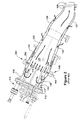
- Figure 2 illustrates an exemplary combustor 106 in a gas turbine engine in which embodiments of the present invention may be used.
- the combustor 106 may include a headend 111, which generally includes the various manifolds that supply the necessary air and fuel to the combustor 106, and an end cover 112.
- the combustor 106 may be enclosed within a combustor casing 114, as shown.
- a plurality of fuel lines 117 may extend through the end cover 112 to fuel injectors or fuel nozzles 118 that are positioned at the aft end of a cap assembly 119.
- the fuel nozzles 118 which may also be referred to as primary fuel injectors, represent the main source of fuel within the combustor 106.
- the cap assembly 119 generally is cylindrical in shape and fixed at a forward end to the end cover 112.
- the cap assembly 119 may be surrounded by the combustor casing 114. It will be appreciated by those of ordinary skill in the art that between the combustor casing 114 and the cap assembly 119, a combustor casing annulus 120 is formed.
- the fuel nozzles 118 bring together a mixture of fuel and air for combustion.
- the fuel for example, may be natural gas and the air may be compressed air (the flow of which is indicated in Figure 2 by the several arrows) supplied from the compressor 104.
- a combustion chamber 121 downstream of the fuel nozzles 118 is a combustion chamber 121 in which the combustion occurs.
- the combustion chamber 121 is generally defmed by a liner 123, which is enclosed within a flow sleeve 124. Between the flow sleeve 124 and the liner 123 an annulus is formed.
- a transition duct 126 transitions the flow from the circular cross section of the liner 123 to an annular cross section as it travels downstream to the turbine section (not shown in Figure 4 ).
- An impingement sleeve or outer wall 127 (hereinafter “outer wall 127”) may enclose the transition duct 126, also creating an annulus between the outer wall 127 and the transition duct 126.
- a transition piece aft frame 128 may direct the flow of the working fluid toward the airfoils that are positioned in the first stage of the turbine 108.
- the flow sleeve 124 and the outer wall 127 typically have impingement apertures (not shown in Figure 2 ) formed therethrough which allow an impinged flow of compressed air from the compressor 106 to enter the cavities formed between the flow sleeve 124 and the liner 123 and between the outer wall 127 and the transition duct 126.
- the flow of compressed air through the impingement apertures convectively cools the exterior surfaces of the liner 123 and the transition duct 126.
- the cap assembly 119 may include a series of inlets 130 through which the supply of compressed air enters the interior of the cap assembly 119.
- the inlets 130 may be arranged parallel to each other, being spaced around the circumference of the cylindrical cap assembly 119, though other configurations are possible. In this arrangement, it will be appreciated that struts are defined between each of the inlets 130, which support the cap assembly structure during operation. It will be appreciated that the compressed air entering the combustor 106 through the flow sleeve 124 and the outer wall 127 is directed toward the cap assembly 119 via the flow annulus formed about the liner 123 and the transition duct 126.
- the compressed air then passes through the combustor casing annulus 120, which, as stated is section of the flow annulus that is formed between the cap assembly 119 and the combustor casing 114. Then, the compressed air enters the cap assembly 119 via the inlets 130, which are typically formed toward the forward end of the cap assembly 119. Upon entering the cap assembly 119, the flow of compressed air turn approximately 180° such that it moves toward the fuel nozzles 118 that are positioned toward the aft end of the cap assembly 119.
- combustor casing fuel injector 160 includes a fuel injector within the combustion system of a gas turbine engine 100 that injects fuel into the flow path at a position that is downstream of the compressor 104 and upstream of the fuel nozzles 118.
- a combustor casing fuel injector 160 is defined as a fuel injector that is positioned to inject fuel into the combustor casing annulus 120.
- Figure 2 provides an example of this type of combustor casing fuel injector 160.
- Figure 2 depicts an annular quaternary fuel distributor, which, as one of ordinary skill in the art will appreciate, is a known type of combustor casing fuel injector 160.
- this type of fuel injection system injects fuel into the compressor discharge as it moves through the combustor casing annulus 120. Premixing fuel in this manner may be employed to mitigate combustor instability, to provide better fuel/air mixing, improve flame holding margin of the downstream fuel nozzles, as well as to reduce NOx, CO or other emissions,
- the exemplary annular quaternary fuel distributor 160 includes an annular fuel manifold 162 that may encircle (either in segments or continuously) the combustor 106.
- the fuel manifold 162 typically abuts and is attached to the combustor casing 114.
- the fuel manifold 162 may be formed as an integral component of the combustor casing 114.
- the fuel manifold 162 may include one or more manifold inlets 164 through which a supply of fuel is delivered to the fuel manifold 162.
- the annular quaternary fuel distributor 160 also may include a plurality of fuel injectors 166 spaced at intervals around the combustor 106. As shown, the fuel injectors 166 often are formed as pegs (though other configurations are possible). The fuel injectors 166 may defme a fuel passageway 167 that extends from the fuel manifold 162 to a position within the flow annulus where injection of the fuel takes place.
- the term "flow annulus" may be used to refer to the annulus formed between the combustor casing 114 and the structure enclosed within the combustor casing 114 (which, includes, the cap assembly 119, the liner 123, and the transition duct 126).
- the fuel injectors 166 are positioned such that the fuel is injected into the combustor casing annulus 120 that is formed between the cap assembly 119 and the combustor casing 114.
- the fuel injector 166 may include an injector inlet 168.
- the injector inlet 168 may be positioned on an inner radial surface 169 of the fuel manifold 162 and may extend to injector outlets 170 that are positioned within the combustor casing annulus 120 (or other preferred injection location).
- the injector outlets 170 may be positioned near the distal end of the fuel injector 166. It will be appreciated that the fuel injectors 166 may be installed through the combustor casing 114.
- the main function of the combustor casing fuel injector 160 is to inject fuel into the flow of air upstream of the fuel nozzles 118 so that a desirable fuel-air mixture is created.
- the combustor casing fuel injector 160 may inject the fuel into the flow of compressed air at a position upstream of where the flow enters the interior of the cap assembly 119 (i.e., upstream of the inlets 130).
- the use of the combustor casing fuel injector 160 of Figure 2 is exemplary only. Embodiments of the present invention may be applicable to other types of combustor casing fuel injectors 160.
- combustor casing fuel injectors are susceptible to having portions of their fuel flowpath blocked by debris, which is typically in the form of rust dislodged from within the fuel manifold 162. As one of ordinary skill in the art will appreciate, this may cause damage to the combustion system, inefficient operation, and other issues. As stated, addressing this issue by using rust-free materials within the fuel manifold 162 is unsatisfactory due to high costs. In addition, the usage of coatings to prevent rusting has proven unworkable.
- FIG. 4 is a cross-sectional view of a combustor casing fuel injector 160 in accordance with an exemplary embodiment of the present invention.
- the fuel injector 166 may include a protruding injector inlet 171.
- the protruding injector inlet comprises a section of the fuel injector 166 that juts from the inner radial surface 169 of the fuel manifold 162 to a position within the interior of the fuel manifold 162 and provides an injector inlet that is offset from the interior walls of the fuel manifold, as described in more detail below.
- the protruding injector inlet 171 may include a protrusion that extends from a position on the inner radial surface 169 of the fuel manifold 162 to a position near the radial center of the fuel manifold 162.
- the protruding injector inlet 171, as illustrated, may include a plurality of filtering apertures 172, which provide an inlet through which fuel within the fuel manifold 162 may enter the fuel passageway 167 of the fuel injector 166.
- the filtering apertures 172 each may include a position on the protruding injector inlet such that a minimum aperture offset or clearance 174 is maintained between the radial height of the filtering aperture 172 and the inner radial surface 169 of the fuel manifold 162. It will be appreciated that, formed in this way, the protruding injector inlet 171 includes features similar to that of certain types of standpipe drains. This is because the protruding injector inlet 171 is configured to drain fuel from a position that is offset a distance from the surface through which the fuel is drained.
- the plurality of filtering apertures 172 may be positioned on the protruding injector inlet 171 such that each maintains at least a minimum aperture clearance or offset 174 from the inner radial surface 169 of the fuel manifold 162.
- the length of the protruding injector inlet 171 and the positioning of the filtering apertures 172 on the protruding injector inlet may be configured such that a minimum aperture clearance or offset 176 from an outer radial surface 177 of the fuel manifold 162 is maintained.
- the filtering apertures 172 include a location near the radial center of the fuel manifold 162.
- the protruding injector inlet 171 extends from the inner radial surface 169 of the fuel manifold 162 in a manner such that it is approximately perpendicular to the inner radial surface 169.
- the fuel injector 166 may be approximately cylindrical in shape.
- the section of the fuel injector 166 that comprises the protruding injector inlet 171 also may be cylindrical in shape and, as described, may define a cylindrically fuel passageway 167 within it, as shown.
- the fuel passageway 167 may extend from the filtering apertures 172 within the fuel manifold 162 to the injector outlets 170 within the combustor casing annulus.
- the fuel injectors 166 often are formed as pegs or cylindrically-shaped components, it will be appreciated that the present invention may be employed in fuel injectors having a different shape.
- the protruding injector inlet 171 may include a plurality of filtering apertures 172.
- the filtering apertures 172 may be positioned on the protruding injector inlet 171 such that fuel is allowed to flow into the fuel passageway 167 at positions that are offset from the inner radial surface 169 of the fuel manifold 162. It will be appreciated that this offset allows the filtering apertures 172 to draw from a layer of fuel within the fuel manifold 162 that would typically contains less debris (including rust debris) than if the fuel inlet were otherwise located, for example, such as the manner in which the injector inlet 168 is configured in Figure 3 .
- the debris (particularly rust debris) will tend to settle toward the inner radial surface 169 of the fuel manifold 162. As such, the debris will be less likely to be drawn into filtering apertures 172 which are offset a minimum distance from this surface.
- the filtering apertures 172 may be desirably offset from the outer radial surface 177 of the fuel manifold 162. It will be appreciated that, depending on the angular position of the protruding injector inlet 171 along the exterior of the combustor casing 114, gravitational effects may cause the debris to settle toward either of the interior radial surfaces of the fuel manifold 162, i.e., the inner radial surface 169 or the outer radial surface 177. In addition, it will be appreciated that centrifugal forces may cause debris to settle toward the outer radial surface 177 depending on the flow patterns within the manifold 162.
- the fuel injectors 166 will be less likely to become clogged with the debris that typically tends to settle toward the radial surfaces within the fuel manifold 162. Accordingly, the fuel injectors 166 will be less likely to become clogged with ingested debris. This is particularly true of debris, like rust, that is heavy relative to the fuel flowing through the combustion system, as heavy particles will settle more rapidly.
- the positioning of the filtering apertures 172 varies in accordance to the gravitational effects at the particular location of one of the protruding injector inlets 171 within the fuel manifold 162.
- the filtering apertures 172 may be configured on the protruding injector inlet 171 such that an increased aperture clearance 174 from the inner radial surface 169 is maintained.
- the filtering apertures 172 may be configured on the protruding injector inlet 171 such that an increased aperture clearance 176 from the outer radial surface 177 is maintained.
- the filtering apertures 172 are offset from the inner radial surface 169 by at least a fixed distance. It will be appreciated that the minimum distance by which the filtering apertures 172 are offset from the inner radial surface 169 may also be expressed as a percentage of the overall radial height of the fuel manifold 162. It has been found that performance advantages are noticed when this offset is at least 20% of the radial height of the fuel manifold 162. More preferably, this offset is at least 40% of the radial height of the fuel manifold 162.
- the filtering apertures 172 are offset from the outer radial surface 177 by at least a fixed distance.
- the distance by which the filtering apertures 172 are offset from the outer radial surface 177 may also be expressed as a percentage of the overall height of the fuel manifold 162. It has been found that performance advantages are noticed when this offset from the outer radial surface 177 is at least 20% of the radial height of the fuel manifold 162. More preferably, this offset is at least 40% of the radial height of the fuel manifold 162.
- filtering apertures 172 each may be sized such that the apertures filter or block debris from entering the fuel passageway 167 of the fuel injector 166.
- the filtering apertures 172 include a circular shape, though other shapes are possible.
- the filtering apertures 172 are sized in relation to the injector outlets 170 positioned at the other end of the fuel injectors 166. In this case, the filtering apertures 172 generally are sized such that they are no larger than the injector outlets 170.
- the filtering apertures 172 are sized such that they are no larger than 70% of the size of the injector outlets 170. It will be appreciated that, in this case, the 30% buffer provides a greater likelihood that any debris that passes through the filtering apertures 172 will also pass through the injector outlets 170, even when multiple pieces of debris are flowing through the injector outlets 170 at the same time.
- size may refer to diameter. If, instead, the filtering apertures 172 and the injector outlets 170 are rectangular in shape, “size” may refer to the distance from opposing corners. More generally, “size” may refer to the longest linear span across the filtering aperture 172/injector outlet 170.
- the protruding injector inlet 171 may include a sufficient number of filtering apertures 172 so that an increased pressure drop is not experienced across the fuel injectors 166. In this manner, the present invention may be implemented such that an appreciable pressure drop across the injection system is not experienced.
- the present invention provides a convenient, cost-effective solution to a nagging problem. This allows the casing and annulus to be made out of carbon steel and not require higher cost materials, coatings, or other processes that add cost.
Abstract
Description
- The present disclosure generally relates to apparatus and systems for fuel passages within gas turbine engines, and more particularly relates to apparatus and systems for fuel passages that reduce flow variation due to rust and debris within a fuel supply.
- Gas turbine engines include a compressor, a combustor, and a turbine. The compressor creates compressed air, which is supplied to the combustor. The combustor combusts the compressed air with fuel to generate an air-fuel mixture, which is supplied to the turbine. The turbine extracts energy from the air-fuel mixture to drive a load. In many cases, the gas turbine includes a number of combustors. The combustors may be positioned between the compressor and the turbine. For example, the compressor and the turbine may be aligned along a common axis, and the combustors may be positioned between the compressor and the turbine at an entrance to the turbine, in a circular array about the common axis. In operation, air from the compressor may travel into the turbine through one of the combustors.
- The combustors may be operated at a relatively high temperature to ensure the mixture of air and fuel is adequately combusted, improving efficiency. One problem with operating the combustors at a high temperature is that a relatively high level of nitrogen oxides (NOx) may be generated, which may have a negative impact on the environment.
- To reduce NOx emissions, many modem gas turbines employ fuel nozzles. For example, each combustor may be supported by a number of fuel nozzles, which may be positioned in a circular array about the combustor. During normal operation, the air from the compressor enters the combustor via the fuel nozzles. Within the fuel nozzles the air is mixed with fuel to form an air-fuel mixture. The air-fuel mixture is then combusted in the combustor. Pre-mixing the air and fuel permits operating the combustors at relatively lower temperatures, which reduces the NOx produced as a by-product of the combustion process.
- To achieve further performance advantages, many combustors employ fuel injectors that are positioned upstream of the fuel nozzles. One such system, for example, is a fuel injector that is integrated within the combustor casing, which may be referred to herein as a combustor casing fuel injector. This type of fuel injector may be referred to as an annular quaternary fuel distributor. As described in more detail below, this type of system injects fuel into the compressed air discharged by the compressor as this flow of air moves toward the fuel nozzles. In certain cases, as described in more detail below, the combustor casing fuel injector injects fuel into an annulus passageway that is defined by the combustor casing and the cap assembly. It will be appreciated by one of ordinary skill in the art that pre-mixing fuel in this manner may be employed to mitigate combustor instability, to provide better fuel/air mixing, improve flame holding margin of the downstream fuel nozzles, as well as to reduce NOx emissions.
- However, combustor casing fuel injectors present their own problems. Typically, in such systems, fuel is delivered into the combustion system by flowing from the gas manifold into an annulus that is integral to the combustion casing. From there the fuel flows down individual peg injectors or pegs that protrude into the air flow stream (i.e., into the annulus passageway that is defined between the combustor casing and the cap assembly). The fuel of the combustor casing fuel injector then is injected into the flowstream via small holes (∼.05") that are positioned along the peg injectors. It will be appreciated that this fuel mixes with the flow of compressed air and, downstream, is combusted within the burning zone or combustion chamber of the combustor.
- In order meet cost objectives, the annular fuel manifold of the combustor casing fuel injector is constructed as an integral component of the combustor casing. As such, the annular fuel manifold is made of carbon steel, which, over time, means that rust will develop within this fuel passageway. Liberated rust pieces or other debris within the supply of fuel flow down into the pegs and cause a blockage, which may block fuel from flowing into the pegs, flowing through the pegs, or exiting the pegs through the injection holes. It will be appreciated that such blocked may lead to performance issues, such as less efficient engine operation, flame holding, emission problems, etc.
- One solution, calls for the combustor casing fuel manifold to be made from materials that will not rust, such as Inco 625 alloy. This, however, raises costs considerably. Coatings that prevent rust also have been tested; however, as of yet, these have not proven successful. Accordingly, there is a need for apparatus and systems that effectively prevent rust and other debris from clogging combustor casing fuel injectors, while remaining cost-effective in application.
- The present application thus describes a combustor casing fuel injector in a combustor of a combustion turbine engine, the combustor including a combustor casing that encloses internal structure of the combustor, wherein the combustor casing fuel injector includes a fuel manifold adjacent to an outer surface of the combustor casing. In certain embodiments, the combustor casing fuel injector includes a fuel injector; wherein the fuel injector extends through the combustor casing from a position within the fuel manifold to a predetermined fuel injection location; and wherein the fuel injector includes a protruding injector inlet within the fuel manifold.
- These and other features of the present application will become apparent upon review of the following detailed description of the preferred embodiments when taken in conjunction with the drawings and the appended claims.
- Embodiments of the present invention will now be described, by way of example only, with reference to the accompanying drawings in which:
-
Figure 1 is a cross-sectional view of a known gas turbine engine, schematically illustrating a combustion system in which embodiments of the present invention may be employed. -
Figure 2 is a cross-sectional view of a known combustor, schematically illustrating a fuel passage of conventional design. -
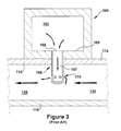
Figure 3 is a cross-sectional view of the fuel passage ofFigure 2 . -
Figure 4 is a cross-sectional view of a fuel passage within a combustor, schematically illustrating an exemplary embodiment in accordance with the present invention. -
Figure 1 is a partial cross-sectional view of a knowngas turbine engine 100 in which embodiments of the present invention may be used. As shown, thegas turbine engine 100 generally includes anintake section 102, acompressor 104, one ormore combustors 106, aturbine 108, and anexhaust section 110. Eachcombustor 106 may include one ormore fuel nozzles 118, as shown inFigure 2 . Thefuel nozzles 118 may be in parallel to each other in an array. For example, thefuel nozzles 118 may be arranged about an entrance to thecombustor 106, such as in a circular configuration about a longitudinal axis of thecombustor 106. - A flow path may be defined through the
gas turbine 100. During normal operation, air may enter thegas turbine 100 through theintake section 102. The air may flow into thecompressor 104, which may compress the air to form compressed air. The compressed air may flow through thefuel nozzles 118, which may mix the compressed air with fuel to form an air-fuel mixture. The air-fuel mixture may flow into thecombustor 106, which may burn the air-fuel mixture to generate hot gases. The hot gases may flow into theturbine 108, which may extract energy from the hot gases, forming exhaust. Thereafter, the exhaust may be exhausted from thegas turbine 100 through theexhaust section 110. -
Figure 2 illustrates anexemplary combustor 106 in a gas turbine engine in which embodiments of the present invention may be used. As one of ordinary skill in the art will appreciate, thecombustor 106 may include aheadend 111, which generally includes the various manifolds that supply the necessary air and fuel to thecombustor 106, and anend cover 112. Thecombustor 106 may be enclosed within acombustor casing 114, as shown. A plurality offuel lines 117 may extend through theend cover 112 to fuel injectors orfuel nozzles 118 that are positioned at the aft end of acap assembly 119. Thefuel nozzles 118, which may also be referred to as primary fuel injectors, represent the main source of fuel within thecombustor 106. It will be appreciated that thecap assembly 119 generally is cylindrical in shape and fixed at a forward end to theend cover 112. Thecap assembly 119 may be surrounded by thecombustor casing 114. It will be appreciated by those of ordinary skill in the art that between thecombustor casing 114 and thecap assembly 119, acombustor casing annulus 120 is formed. - In general, the
fuel nozzles 118 bring together a mixture of fuel and air for combustion. The fuel, for example, may be natural gas and the air may be compressed air (the flow of which is indicated inFigure 2 by the several arrows) supplied from thecompressor 104. As one of ordinary skill in the art will appreciate, downstream of thefuel nozzles 118 is acombustion chamber 121 in which the combustion occurs. Thecombustion chamber 121 is generally defmed by aliner 123, which is enclosed within aflow sleeve 124. Between theflow sleeve 124 and theliner 123 an annulus is formed. From theliner 123, atransition duct 126 transitions the flow from the circular cross section of theliner 123 to an annular cross section as it travels downstream to the turbine section (not shown inFigure 4 ). An impingement sleeve or outer wall 127 (hereinafter "outer wall 127") may enclose thetransition duct 126, also creating an annulus between theouter wall 127 and thetransition duct 126. At the downstream end of thetransition duct 126, a transition piece aftframe 128 may direct the flow of the working fluid toward the airfoils that are positioned in the first stage of theturbine 108. It will be appreciated that theflow sleeve 124 and theouter wall 127 typically have impingement apertures (not shown inFigure 2 ) formed therethrough which allow an impinged flow of compressed air from thecompressor 106 to enter the cavities formed between theflow sleeve 124 and theliner 123 and between theouter wall 127 and thetransition duct 126. The flow of compressed air through the impingement apertures convectively cools the exterior surfaces of theliner 123 and thetransition duct 126. - As shown, the
cap assembly 119 may include a series ofinlets 130 through which the supply of compressed air enters the interior of thecap assembly 119. Theinlets 130 may be arranged parallel to each other, being spaced around the circumference of thecylindrical cap assembly 119, though other configurations are possible. In this arrangement, it will be appreciated that struts are defined between each of theinlets 130, which support the cap assembly structure during operation. It will be appreciated that the compressed air entering thecombustor 106 through theflow sleeve 124 and theouter wall 127 is directed toward thecap assembly 119 via the flow annulus formed about theliner 123 and thetransition duct 126. The compressed air then passes through thecombustor casing annulus 120, which, as stated is section of the flow annulus that is formed between thecap assembly 119 and thecombustor casing 114. Then, the compressed air enters thecap assembly 119 via theinlets 130, which are typically formed toward the forward end of thecap assembly 119. Upon entering thecap assembly 119, the flow of compressed air turn approximately 180° such that it moves toward thefuel nozzles 118 that are positioned toward the aft end of thecap assembly 119. - It will be appreciated that the combustor of
Figure 2 further includes a fuel injector upstream of thefuel nozzles 118, which will be referred to herein as a combustorcasing fuel injector 160. As stated, and unless otherwise stated, a combustorcasing fuel injector 160 includes a fuel injector within the combustion system of agas turbine engine 100 that injects fuel into the flow path at a position that is downstream of thecompressor 104 and upstream of thefuel nozzles 118. In certain embodiments, however, a combustorcasing fuel injector 160 is defined as a fuel injector that is positioned to inject fuel into thecombustor casing annulus 120.Figure 2 provides an example of this type of combustorcasing fuel injector 160. - More specifically,
Figure 2 depicts an annular quaternary fuel distributor, which, as one of ordinary skill in the art will appreciate, is a known type of combustorcasing fuel injector 160. As described in more detail below, this type of fuel injection system injects fuel into the compressor discharge as it moves through thecombustor casing annulus 120. Premixing fuel in this manner may be employed to mitigate combustor instability, to provide better fuel/air mixing, improve flame holding margin of the downstream fuel nozzles, as well as to reduce NOx, CO or other emissions, - As illustrated in
Figure 2 , the exemplary annularquaternary fuel distributor 160 includes anannular fuel manifold 162 that may encircle (either in segments or continuously) thecombustor 106. Thefuel manifold 162 typically abuts and is attached to thecombustor casing 114. As stated, thefuel manifold 162 may be formed as an integral component of thecombustor casing 114. Thefuel manifold 162 may include one or moremanifold inlets 164 through which a supply of fuel is delivered to thefuel manifold 162. - As shown in more detail in
Figure 3 , the annularquaternary fuel distributor 160 also may include a plurality offuel injectors 166 spaced at intervals around thecombustor 106. As shown, thefuel injectors 166 often are formed as pegs (though other configurations are possible). Thefuel injectors 166 may defme afuel passageway 167 that extends from thefuel manifold 162 to a position within the flow annulus where injection of the fuel takes place. As used herein, the term "flow annulus" may be used to refer to the annulus formed between thecombustor casing 114 and the structure enclosed within the combustor casing 114 (which, includes, thecap assembly 119, theliner 123, and the transition duct 126). Often, thefuel injectors 166 are positioned such that the fuel is injected into thecombustor casing annulus 120 that is formed between thecap assembly 119 and thecombustor casing 114. At a connection with thefuel manifold 162, thefuel injector 166 may include aninjector inlet 168. Per conventional design, theinjector inlet 168 may be positioned on an innerradial surface 169 of thefuel manifold 162 and may extend to injectoroutlets 170 that are positioned within the combustor casing annulus 120 (or other preferred injection location). Theinjector outlets 170 may be positioned near the distal end of thefuel injector 166. It will be appreciated that thefuel injectors 166 may be installed through thecombustor casing 114. It will be further appreciated that the main function of the combustorcasing fuel injector 160 is to inject fuel into the flow of air upstream of thefuel nozzles 118 so that a desirable fuel-air mixture is created. In certain embodiments, the combustorcasing fuel injector 160 may inject the fuel into the flow of compressed air at a position upstream of where the flow enters the interior of the cap assembly 119 (i.e., upstream of the inlets 130). Those of ordinary skill in the art will appreciate that the use of the combustorcasing fuel injector 160 ofFigure 2 is exemplary only. Embodiments of the present invention may be applicable to other types of combustorcasing fuel injectors 160. - As described, known types of combustor casing fuel injectors, particularly annular quaternary fuel injectors with a peg design, are susceptible to having portions of their fuel flowpath blocked by debris, which is typically in the form of rust dislodged from within the
fuel manifold 162. As one of ordinary skill in the art will appreciate, this may cause damage to the combustion system, inefficient operation, and other issues. As stated, addressing this issue by using rust-free materials within thefuel manifold 162 is unsatisfactory due to high costs. In addition, the usage of coatings to prevent rusting has proven unworkable. -
Figure 4 is a cross-sectional view of a combustorcasing fuel injector 160 in accordance with an exemplary embodiment of the present invention. As shown, thefuel injector 166 may include a protrudinginjector inlet 171. In accordance with the present invention, the protruding injector inlet comprises a section of thefuel injector 166 that juts from the innerradial surface 169 of thefuel manifold 162 to a position within the interior of thefuel manifold 162 and provides an injector inlet that is offset from the interior walls of the fuel manifold, as described in more detail below. Accordingly, in certain embodiments, the protrudinginjector inlet 171 may include a protrusion that extends from a position on the innerradial surface 169 of thefuel manifold 162 to a position near the radial center of thefuel manifold 162. The protrudinginjector inlet 171, as illustrated, may include a plurality offiltering apertures 172, which provide an inlet through which fuel within thefuel manifold 162 may enter thefuel passageway 167 of thefuel injector 166. Thefiltering apertures 172 each may include a position on the protruding injector inlet such that a minimum aperture offset orclearance 174 is maintained between the radial height of thefiltering aperture 172 and the innerradial surface 169 of thefuel manifold 162. It will be appreciated that, formed in this way, the protrudinginjector inlet 171 includes features similar to that of certain types of standpipe drains. This is because the protrudinginjector inlet 171 is configured to drain fuel from a position that is offset a distance from the surface through which the fuel is drained. - As stated, the plurality of
filtering apertures 172 may be positioned on the protrudinginjector inlet 171 such that each maintains at least a minimum aperture clearance or offset 174 from the innerradial surface 169 of thefuel manifold 162. In certain embodiments, the length of the protrudinginjector inlet 171 and the positioning of thefiltering apertures 172 on the protruding injector inlet may be configured such that a minimum aperture clearance or offset 176 from an outerradial surface 177 of thefuel manifold 162 is maintained. In certain preferred embodiments, thefiltering apertures 172 include a location near the radial center of thefuel manifold 162. - In certain embodiments, the protruding
injector inlet 171 extends from the innerradial surface 169 of thefuel manifold 162 in a manner such that it is approximately perpendicular to the innerradial surface 169. In certain embodiments, thefuel injector 166 may be approximately cylindrical in shape. The section of thefuel injector 166 that comprises the protrudinginjector inlet 171 also may be cylindrical in shape and, as described, may define acylindrically fuel passageway 167 within it, as shown. Thefuel passageway 167 may extend from thefiltering apertures 172 within thefuel manifold 162 to theinjector outlets 170 within the combustor casing annulus. Though, thefuel injectors 166 often are formed as pegs or cylindrically-shaped components, it will be appreciated that the present invention may be employed in fuel injectors having a different shape. - As stated, the protruding
injector inlet 171 may include a plurality offiltering apertures 172. Thefiltering apertures 172 may be positioned on the protrudinginjector inlet 171 such that fuel is allowed to flow into thefuel passageway 167 at positions that are offset from the innerradial surface 169 of thefuel manifold 162. It will be appreciated that this offset allows thefiltering apertures 172 to draw from a layer of fuel within thefuel manifold 162 that would typically contains less debris (including rust debris) than if the fuel inlet were otherwise located, for example, such as the manner in which theinjector inlet 168 is configured inFigure 3 . More specifically, given the configuration shown inFigure 4 , the debris (particularly rust debris) will tend to settle toward the innerradial surface 169 of thefuel manifold 162. As such, the debris will be less likely to be drawn intofiltering apertures 172 which are offset a minimum distance from this surface. - Further, as stated, the
filtering apertures 172 may be desirably offset from the outerradial surface 177 of thefuel manifold 162. It will be appreciated that, depending on the angular position of the protrudinginjector inlet 171 along the exterior of thecombustor casing 114, gravitational effects may cause the debris to settle toward either of the interior radial surfaces of thefuel manifold 162, i.e., the innerradial surface 169 or the outerradial surface 177. In addition, it will be appreciated that centrifugal forces may cause debris to settle toward the outerradial surface 177 depending on the flow patterns within themanifold 162. Accordingly, by having the filteringapertures 172 positioned within thefuel manifold 162 such that each maintains a position toward the radial center of the manifold, thefuel injectors 166 will be less likely to become clogged with the debris that typically tends to settle toward the radial surfaces within thefuel manifold 162. Accordingly, thefuel injectors 166 will be less likely to become clogged with ingested debris. This is particularly true of debris, like rust, that is heavy relative to the fuel flowing through the combustion system, as heavy particles will settle more rapidly. - In one preferred embodiment, the positioning of the filtering apertures 172 (i.e., the maintained
aperture clearances 174, 176) varies in accordance to the gravitational effects at the particular location of one of the protrudinginjector inlets 171 within thefuel manifold 162. Thus, where gravitational effects would tend to settle debris toward the innerradial surface 169 of thefuel manifold 162, thefiltering apertures 172 may be configured on the protrudinginjector inlet 171 such that an increasedaperture clearance 174 from the innerradial surface 169 is maintained. Where the opposite is true (i.e., where gravitational effects would tend to settle debris toward the outerradial surface 177 of the fuel manifold 162), thefiltering apertures 172 may be configured on the protrudinginjector inlet 171 such that an increasedaperture clearance 176 from the outerradial surface 177 is maintained. - In certain embodiments, the
filtering apertures 172, generally, are offset from the innerradial surface 169 by at least a fixed distance. It will be appreciated that the minimum distance by which thefiltering apertures 172 are offset from the innerradial surface 169 may also be expressed as a percentage of the overall radial height of thefuel manifold 162. It has been found that performance advantages are noticed when this offset is at least 20% of the radial height of thefuel manifold 162. More preferably, this offset is at least 40% of the radial height of thefuel manifold 162. - In certain embodiments, the
filtering apertures 172 are offset from the outerradial surface 177 by at least a fixed distance. The distance by which thefiltering apertures 172 are offset from the outerradial surface 177 may also be expressed as a percentage of the overall height of thefuel manifold 162. It has been found that performance advantages are noticed when this offset from the outerradial surface 177 is at least 20% of the radial height of thefuel manifold 162. More preferably, this offset is at least 40% of the radial height of thefuel manifold 162. - Additionally, per embodiments of the present invention, filtering
apertures 172 each may be sized such that the apertures filter or block debris from entering thefuel passageway 167 of thefuel injector 166. In some preferred embodiments, thefiltering apertures 172 include a circular shape, though other shapes are possible. In preferred embodiments, thefiltering apertures 172 are sized in relation to theinjector outlets 170 positioned at the other end of thefuel injectors 166. In this case, thefiltering apertures 172 generally are sized such that they are no larger than theinjector outlets 170. In this way, debris that is small enough to enter thefuel passageway 167 of thefuel injector 166 via thefiltering apertures 172 should also be small enough to flow out of thefuel injector 166 through theinjector outlets 170. In a preferred embodiment, thefiltering apertures 172 are sized such that they are no larger than 70% of the size of theinjector outlets 170. It will be appreciated that, in this case, the 30% buffer provides a greater likelihood that any debris that passes through thefiltering apertures 172 will also pass through theinjector outlets 170, even when multiple pieces of debris are flowing through theinjector outlets 170 at the same time. When thefiltering apertures 172 andinjector outlets 170 are circular in shape, "size" may refer to diameter. If, instead, thefiltering apertures 172 and theinjector outlets 170 are rectangular in shape, "size" may refer to the distance from opposing corners. More generally, "size" may refer to the longest linear span across thefiltering aperture 172/injector outlet 170. - Further, the protruding
injector inlet 171 may include a sufficient number offiltering apertures 172 so that an increased pressure drop is not experienced across thefuel injectors 166. In this manner, the present invention may be implemented such that an appreciable pressure drop across the injection system is not experienced. - Those of ordinary skill in the art will appreciate that the present invention provides a convenient, cost-effective solution to a nagging problem. This allows the casing and annulus to be made out of carbon steel and not require higher cost materials, coatings, or other processes that add cost.
- As one of ordinary skill in the art will appreciate, the many varying features and configurations described above in relation to the several exemplary embodiments may be further selectively applied to form the other possible embodiments of the present invention. For the sake of brevity and taking into account the abilities of one of ordinary skill in the art, all of the possible iterations is not provided or discussed in detail, though all combinations and possible embodiments embraced by the several claims below or otherwise are intended to be part of the instant application. In addition, from the above description of several exemplary embodiments of the invention, those skilled in the art will perceive improvements, changes and modifications. Such improvements, changes and modifications within the skill of the art are also intended to be covered by the appended claims. Further, it should be apparent that the foregoing relates only to the described embodiments of the present application and that numerous changes and modifications may be made herein without departing from the spirit and scope of the application as defmed by the following claims and the equivalents thereof.
Claims (15)
- A combustor casing fuel injector (160) in a combustor (106) of a combustion turbine engine (100), the combustor (106) including a combustor casing (114) that encloses internal structure of the combustor (106), wherein the combustor casing fuel injector (160) includes a fuel manifold (162) adjacent to an outer surface of the combustor casing, the combustor casing (114) fuel injector comprising:a fuel injector (166);wherein the fuel injector (166) extends through the combustor casing (114) from a position within the fuel manifold (162) to a predetermined fuel injection location; andwherein the fuel injector (166) includes a protruding injector inlet (171) within the fuel manifold (162).
- The combustor casing fuel injector (160) according to claim 1, wherein the protruding injector inlet (171) comprises a protrusion, which juts from an inner surface (169) of the fuel manifold (162), and a plurality of apertures (172);
wherein fuel injector (166) includes a fuel passageway (167) defined therein; wherein each of the plurality of apertures (172) comprises an inlet (130) through which the fuel manifold (162) fluidly communicates with the fluid passageway (167); and
wherein the plurality of apertures (172) comprise a first minimum aperture offset (174), the first minimum aperture offset (174) comprising a minimum distance by which each of the apertures is offset from the inner surface (169) of the fuel manifold (162). - The combustor casing fuel injector according to claim 2, wherein the predetermined fuel injection location comprises a flow annulus (120) that is formed between a combustor casing (114) and the internal structure;
wherein the fuel injector (166) comprises an injector outlet (170) disposed within the flow annulus (120) that is configured to fluidly connect the fuel passageway (167) of the fuel injector (166) to the flow annulus (120);
wherein the fuel passageway (167) is configured to fluidly connect each of the plurality of apertures (172) to the injector outlet (170); and
wherein the protruding injector inlet (171) comprises an enclosed section that coincides with the first minimum aperture offset (174), the enclosed structure containing sealed structure that is configured to prevent fuel from entering the fuel passageway (167) at any point along the enclosed section. - The combustor casing fuel injector according to claim 3, wherein the combustor casing fuel injector comprises an annular quaternary fuel distributor; and wherein the fuel manifold (162) comprises an integral component to the combustor casing (114).
- The combustor casing fuel injector according to claim 3, wherein the combustor casing (126) comprises an approximate cylindrical shape;
wherein the fuel manifold (162) comprises an annular fuel manifold that wraps around the combustor casing (114);
wherein the annular fuel manifold comprises an inner radial surface (169), which resides adjacent to the combustor casing (114), and an outer radial surface (177) that opposes the inner radial surface (169) across the fuel manifold (162);
wherein the inner surface from which the protruding injector inlet (171) juts comprises the inner radial surface of the annular fuel manifold (169); and
wherein the protruding injector inlet (171) comprises a section of the fuel injector that juts from the inner radial surface (169) of the fuel manifold (162) to a position near a midpoint between the inner radial surface (169) and the outer radial surface (177). - The combustor casing fuel injector according to claim 5, wherein the combustor casing fuel injector (160) comprises a plurality of fuel injectors (166) that are spaced at intervals around the combustor casing (114);
wherein the internal structure comprises a cap assembly (119) having an approximate cylindrical shape; and
wherein the predetermined fuel injection location comprises positions within the annulus formed between the cap assembly (119) and the combustor casing (114). - The combustor casing fuel injector (160) according to claim 6, wherein the fuel injector (166) comprises an approximate cylindrical shape;
wherein the fuel passageway (167) within the fuel injector (166) comprises an approximate cylindrical shape; and
wherein the protruding injector inlet (171) extends approximately perpendicular from the inner radial surface of the fuel manifold (169). - The combustor casing fuel injector (160) according to claim 6 or 7, wherein the plurality of apertures (172) comprise a plurality of filtering apertures,
wherein each of the plurality of filtering apertures (172) comprises an aperture (172) having a predetermined size, the predetermined size corresponding to a desired particle size to be filtered by the plurality of filtering apertures (172); and
the protruding injector inlet (171) comprises a length and the filtering apertures (172) comprise a configuration on the protruding injector inlet (171) such that the first minimum aperture offset (174) from the inner radial surface (169) is maintained. - The combustor casing fuel injector according to claim 8, wherein a second minimum aperture offset (176) comprises a minimum distance by which each of the filtering apertures (176) is offset from the outer radial surface (177) of the fuel manifold (162); and
the protruding injector inlet (171) comprises a length and the filtering apertures (172) comprise a configuration on the protruding injector inlet (171) such that the second minimum aperture offset (176) from the outer surface (177) is maintained. - The combustor casing fuel injector according to claim 8, wherein each of the plurality of filtering apertures (172) is sized relative to the injector outlet (170); and
wherein the size of each of the plurality of filtering apertures (172) is no larger than the size of the injector outlet (170). - The combustor casing fuel injector (160) according to claim 10, wherein the size of each of the plurality of filtering apertures (172) is no larger than 70% of the size of the injector outlet (170).
- The combustor casing fuel injector according to any of claims 8 to 11, wherein the number and flow area of the plurality of filtering apertures (172) are configured based upon a desired pressure drop across the fuel injector (166).
- The combustor casing fuel injector according to claim 6, wherein the multiple fuel injectors (166) are located at predetermined angular positions about the combustor casing (114);
wherein the first minimum aperture clearance (174) between the filtering apertures (172) and the inner radial surface (169) of the fuel manifold (162) and the second minimum aperture clearance (176) between the filtering apertures (172) and the outer radial surface (177) of the fuel manifold (162) are configured such that each varies in relation to the expected effect of gravity on sinking debris given the predetermined angular position of each fuel injector (166). - The combustor casing fuel injector according to claim 13, wherein, at the predetermined angular positions at which the expected effect of gravity settles sinking debris toward the inner radial surface (169) of the fuel manifold (162), the filtering apertures (172) comprise an increased first minimum aperture clearance (174); and
wherein, at the predetermined angular positions at which the expected effect of gravity settles sinking debris toward the outer radial surface (177) of the fuel manifold (162), the filtering apertures (172) comprise an increased second minimum aperture clearance (176). - The combustor casing fuel injector according to any of claims 8 to 14, wherein the fuel manifold (162) comprises a radial height measuring the approximate distance from the inner radial surface (169) to the outer radial surface (177); and
wherein the first and second minimum aperture clearances (174,176) comprises at least 20% of the height of the fuel manifold (162).
Applications Claiming Priority (1)
| Application Number | Priority Date | Filing Date | Title |
|---|---|---|---|
| US13/176,784 US8919125B2 (en) | 2011-07-06 | 2011-07-06 | Apparatus and systems relating to fuel injectors and fuel passages in gas turbine engines |
Publications (2)
| Publication Number | Publication Date |
|---|---|
| EP2543931A1 true EP2543931A1 (en) | 2013-01-09 |
| EP2543931B1 EP2543931B1 (en) | 2020-12-30 |
Family
ID=46508258
Family Applications (1)
| Application Number | Title | Priority Date | Filing Date |
|---|---|---|---|
| EP12175436.0A Active EP2543931B1 (en) | 2011-07-06 | 2012-07-06 | Apparatus and systems relating to fuel injectors and fuel passages in gas turbine engines |
Country Status (3)
| Country | Link |
|---|---|
| US (1) | US8919125B2 (en) |
| EP (1) | EP2543931B1 (en) |
| CN (1) | CN102865597B (en) |
Families Citing this family (19)
| Publication number | Priority date | Publication date | Assignee | Title |
|---|---|---|---|---|
| WO2013002666A1 (en) | 2011-06-30 | 2013-01-03 | General Electric Company | Combustor and method of supplying fuel to the combustor |
| WO2013002669A1 (en) | 2011-06-30 | 2013-01-03 | General Electric Company | Combustor and method of supplying fuel to the combustor |
| JP6154988B2 (en) * | 2012-01-05 | 2017-06-28 | 三菱日立パワーシステムズ株式会社 | Combustor |
| US9170024B2 (en) | 2012-01-06 | 2015-10-27 | General Electric Company | System and method for supplying a working fluid to a combustor |
| US9188337B2 (en) | 2012-01-13 | 2015-11-17 | General Electric Company | System and method for supplying a working fluid to a combustor via a non-uniform distribution manifold |
| US9097424B2 (en) | 2012-03-12 | 2015-08-04 | General Electric Company | System for supplying a fuel and working fluid mixture to a combustor |
| US9151500B2 (en) * | 2012-03-15 | 2015-10-06 | General Electric Company | System for supplying a fuel and a working fluid through a liner to a combustion chamber |
| US9284888B2 (en) | 2012-04-25 | 2016-03-15 | General Electric Company | System for supplying fuel to late-lean fuel injectors of a combustor |
| US9052115B2 (en) | 2012-04-25 | 2015-06-09 | General Electric Company | System and method for supplying a working fluid to a combustor |
| US8677753B2 (en) * | 2012-05-08 | 2014-03-25 | General Electric Company | System for supplying a working fluid to a combustor |
| US8479518B1 (en) * | 2012-07-11 | 2013-07-09 | General Electric Company | System for supplying a working fluid to a combustor |
| US20140123653A1 (en) * | 2012-11-08 | 2014-05-08 | General Electric Company | Enhancement for fuel injector |
| US20140366541A1 (en) * | 2013-06-14 | 2014-12-18 | General Electric Company | Systems and apparatus relating to fuel injection in gas turbines |
| CN105637294A (en) * | 2013-10-11 | 2016-06-01 | 西门子公司 | Heat-protective insert for a fuel line |
| US20150159877A1 (en) * | 2013-12-06 | 2015-06-11 | General Electric Company | Late lean injection manifold mixing system |
| US10139111B2 (en) * | 2014-03-28 | 2018-11-27 | Siemens Energy, Inc. | Dual outlet nozzle for a secondary fuel stage of a combustor of a gas turbine engine |
| US11156164B2 (en) | 2019-05-21 | 2021-10-26 | General Electric Company | System and method for high frequency accoustic dampers with caps |
| US11174792B2 (en) | 2019-05-21 | 2021-11-16 | General Electric Company | System and method for high frequency acoustic dampers with baffles |
| US11371709B2 (en) | 2020-06-30 | 2022-06-28 | General Electric Company | Combustor air flow path |
Citations (4)
| Publication number | Priority date | Publication date | Assignee | Title |
|---|---|---|---|---|
| EP0687864A2 (en) * | 1994-05-21 | 1995-12-20 | ROLLS-ROYCE plc | A gas turbine engine combustion chamber |
| WO1999019674A1 (en) * | 1997-10-13 | 1999-04-22 | Siemens Westinghouse Power Corporation | Combustor with independently controllable fuel flow to different stages |
| US20110083701A1 (en) * | 2009-10-09 | 2011-04-14 | General Electric Company | Process to clean gas turbine fuel chamber components |
| EP2375163A2 (en) * | 2010-04-06 | 2011-10-12 | General Electric Company | Segmented annular ring-manifold quaternary fuel distributor |
Family Cites Families (11)
| Publication number | Priority date | Publication date | Assignee | Title |
|---|---|---|---|---|
| FR2706588B1 (en) * | 1993-06-16 | 1995-07-21 | Snecma | Fuel injection system for combustion chamber. |
| GB9325708D0 (en) * | 1993-12-16 | 1994-02-16 | Rolls Royce Plc | A gas turbine engine combustion chamber |
| US6148617A (en) * | 1998-07-06 | 2000-11-21 | Williams International, Co. L.L.C. | Natural gas fired combustion system for gas turbine engines |
| US6295801B1 (en) * | 1998-12-18 | 2001-10-02 | General Electric Company | Fuel injector bar for gas turbine engine combustor having trapped vortex cavity |
| US6286298B1 (en) * | 1998-12-18 | 2001-09-11 | General Electric Company | Apparatus and method for rich-quench-lean (RQL) concept in a gas turbine engine combustor having trapped vortex cavity |
| US6598383B1 (en) | 1999-12-08 | 2003-07-29 | General Electric Co. | Fuel system configuration and method for staging fuel for gas turbines utilizing both gaseous and liquid fuels |
| US6526741B2 (en) | 2000-12-18 | 2003-03-04 | General Electric Company | Method and apparatus for removing alkali metal contamination from gas turbine liquid fuels |
| US7640726B2 (en) * | 2005-09-28 | 2010-01-05 | Pratt & Whitney Rocketdyne, Inc. | Injector assembly having multiple manifolds for propellant delivery |
| US8549859B2 (en) * | 2008-07-28 | 2013-10-08 | Siemens Energy, Inc. | Combustor apparatus in a gas turbine engine |
| US8281594B2 (en) * | 2009-09-08 | 2012-10-09 | Siemens Energy, Inc. | Fuel injector for use in a gas turbine engine |
| US8752386B2 (en) * | 2010-05-25 | 2014-06-17 | Siemens Energy, Inc. | Air/fuel supply system for use in a gas turbine engine |
-
2011
- 2011-07-06 US US13/176,784 patent/US8919125B2/en active Active
-
2012
- 2012-07-06 EP EP12175436.0A patent/EP2543931B1/en active Active
- 2012-07-06 CN CN201210252404.0A patent/CN102865597B/en active Active
Patent Citations (4)
| Publication number | Priority date | Publication date | Assignee | Title |
|---|---|---|---|---|
| EP0687864A2 (en) * | 1994-05-21 | 1995-12-20 | ROLLS-ROYCE plc | A gas turbine engine combustion chamber |
| WO1999019674A1 (en) * | 1997-10-13 | 1999-04-22 | Siemens Westinghouse Power Corporation | Combustor with independently controllable fuel flow to different stages |
| US20110083701A1 (en) * | 2009-10-09 | 2011-04-14 | General Electric Company | Process to clean gas turbine fuel chamber components |
| EP2375163A2 (en) * | 2010-04-06 | 2011-10-12 | General Electric Company | Segmented annular ring-manifold quaternary fuel distributor |
Also Published As
| Publication number | Publication date |
|---|---|
| EP2543931B1 (en) | 2020-12-30 |
| CN102865597B (en) | 2016-01-27 |
| US8919125B2 (en) | 2014-12-30 |
| US20130008169A1 (en) | 2013-01-10 |
| CN102865597A (en) | 2013-01-09 |
Similar Documents
| Publication | Publication Date | Title |
|---|---|---|
| US8919125B2 (en) | Apparatus and systems relating to fuel injectors and fuel passages in gas turbine engines | |
| EP1760403B1 (en) | Combustor for a gas turbine | |
| US6871501B2 (en) | Method and apparatus to decrease gas turbine engine combustor emissions | |
| CN103453554B (en) | For the fuel injection assemblies and its assemble method that are used in turbogenerator | |
| US7716931B2 (en) | Method and apparatus for assembling gas turbine engine | |
| US8099940B2 (en) | Low cross-talk gas turbine fuel injector | |
| CA2868732C (en) | Turbomachine combustor assembly | |
| CN103375819B (en) | Fuel/air premix system for turbogenerator | |
| US8113000B2 (en) | Flashback resistant pre-mixer assembly | |
| CN107917442B (en) | Dual fuel concentric nozzle for gas turbine | |
| US9951956B2 (en) | Fuel nozzle assembly having a premix fuel stabilizer | |
| JP2014122784A (en) | System for supplying fuel to combustor | |
| US20140060059A1 (en) | Fuel delivery system with a cavity coupled fuel injector | |
| CN102721084A (en) | Combustor crossfire tube having purge holes | |
| US9068750B2 (en) | Combustor with a pre-nozzle mixing cap assembly | |
| JP5998041B2 (en) | Turbomachine component flow sleeve | |
| CN103835772A (en) | Turbomachine with trapped vortex feature | |
| JP4477039B2 (en) | Combustion device for gas turbine engine | |
| US20130227928A1 (en) | Fuel nozzle assembly for use in turbine engines and method of assembling same | |
| JP4477038B2 (en) | Combustion device for gas turbine engine |
Legal Events
| Date | Code | Title | Description |
|---|---|---|---|
| PUAI | Public reference made under article 153(3) epc to a published international application that has entered the european phase |
Free format text: ORIGINAL CODE: 0009012 |
|
| AK | Designated contracting states |
Kind code of ref document: A1 Designated state(s): AL AT BE BG CH CY CZ DE DK EE ES FI FR GB GR HR HU IE IS IT LI LT LU LV MC MK MT NL NO PL PT RO RS SE SI SK SM TR |
|
| AX | Request for extension of the european patent |
Extension state: BA ME |
|
| 17P | Request for examination filed |
Effective date: 20130709 |
|
| RBV | Designated contracting states (corrected) |
Designated state(s): AL AT BE BG CH CY CZ DE DK EE ES FI FR GB GR HR HU IE IS IT LI LT LU LV MC MK MT NL NO PL PT RO RS SE SI SK SM TR |
|
| STAA | Information on the status of an ep patent application or granted ep patent |
Free format text: STATUS: EXAMINATION IS IN PROGRESS |
|
| 17Q | First examination report despatched |
Effective date: 20170223 |
|
| GRAP | Despatch of communication of intention to grant a patent |
Free format text: ORIGINAL CODE: EPIDOSNIGR1 |
|
| STAA | Information on the status of an ep patent application or granted ep patent |
Free format text: STATUS: GRANT OF PATENT IS INTENDED |
|
| INTG | Intention to grant announced |
Effective date: 20200608 |
|
| GRAJ | Information related to disapproval of communication of intention to grant by the applicant or resumption of examination proceedings by the epo deleted |
Free format text: ORIGINAL CODE: EPIDOSDIGR1 |
|
| STAA | Information on the status of an ep patent application or granted ep patent |
Free format text: STATUS: EXAMINATION IS IN PROGRESS |
|
| GRAR | Information related to intention to grant a patent recorded |
Free format text: ORIGINAL CODE: EPIDOSNIGR71 |
|
| GRAS | Grant fee paid |
Free format text: ORIGINAL CODE: EPIDOSNIGR3 |
|
| STAA | Information on the status of an ep patent application or granted ep patent |
Free format text: STATUS: GRANT OF PATENT IS INTENDED |
|
| INTC | Intention to grant announced (deleted) | ||
| GRAA | (expected) grant |
Free format text: ORIGINAL CODE: 0009210 |
|
| STAA | Information on the status of an ep patent application or granted ep patent |
Free format text: STATUS: THE PATENT HAS BEEN GRANTED |
|
| AK | Designated contracting states |
Kind code of ref document: B1 Designated state(s): AL AT BE BG CH CY CZ DE DK EE ES FI FR GB GR HR HU IE IS IT LI LT LU LV MC MK MT NL NO PL PT RO RS SE SI SK SM TR |
|
| INTG | Intention to grant announced |
Effective date: 20201123 |
|
| REG | Reference to a national code |
Ref country code: GB Ref legal event code: FG4D |
|
| REG | Reference to a national code |
Ref country code: AT Ref legal event code: REF Ref document number: 1350311 Country of ref document: AT Kind code of ref document: T Effective date: 20210115 |
|
| REG | Reference to a national code |
Ref country code: DE Ref legal event code: R096 Ref document number: 602012073920 Country of ref document: DE |
|
| REG | Reference to a national code |
Ref country code: IE Ref legal event code: FG4D |
|
| PG25 | Lapsed in a contracting state [announced via postgrant information from national office to epo] |
Ref country code: RS Free format text: LAPSE BECAUSE OF FAILURE TO SUBMIT A TRANSLATION OF THE DESCRIPTION OR TO PAY THE FEE WITHIN THE PRESCRIBED TIME-LIMIT Effective date: 20201230 Ref country code: FI Free format text: LAPSE BECAUSE OF FAILURE TO SUBMIT A TRANSLATION OF THE DESCRIPTION OR TO PAY THE FEE WITHIN THE PRESCRIBED TIME-LIMIT Effective date: 20201230 Ref country code: NO Free format text: LAPSE BECAUSE OF FAILURE TO SUBMIT A TRANSLATION OF THE DESCRIPTION OR TO PAY THE FEE WITHIN THE PRESCRIBED TIME-LIMIT Effective date: 20210330 Ref country code: GR Free format text: LAPSE BECAUSE OF FAILURE TO SUBMIT A TRANSLATION OF THE DESCRIPTION OR TO PAY THE FEE WITHIN THE PRESCRIBED TIME-LIMIT Effective date: 20210331 |
|
| REG | Reference to a national code |
Ref country code: AT Ref legal event code: MK05 Ref document number: 1350311 Country of ref document: AT Kind code of ref document: T Effective date: 20201230 |
|
| PG25 | Lapsed in a contracting state [announced via postgrant information from national office to epo] |
Ref country code: SE Free format text: LAPSE BECAUSE OF FAILURE TO SUBMIT A TRANSLATION OF THE DESCRIPTION OR TO PAY THE FEE WITHIN THE PRESCRIBED TIME-LIMIT Effective date: 20201230 Ref country code: LV Free format text: LAPSE BECAUSE OF FAILURE TO SUBMIT A TRANSLATION OF THE DESCRIPTION OR TO PAY THE FEE WITHIN THE PRESCRIBED TIME-LIMIT Effective date: 20201230 Ref country code: BG Free format text: LAPSE BECAUSE OF FAILURE TO SUBMIT A TRANSLATION OF THE DESCRIPTION OR TO PAY THE FEE WITHIN THE PRESCRIBED TIME-LIMIT Effective date: 20210330 |
|
| REG | Reference to a national code |
Ref country code: NL Ref legal event code: MP Effective date: 20201230 |
|
| PG25 | Lapsed in a contracting state [announced via postgrant information from national office to epo] |
Ref country code: HR Free format text: LAPSE BECAUSE OF FAILURE TO SUBMIT A TRANSLATION OF THE DESCRIPTION OR TO PAY THE FEE WITHIN THE PRESCRIBED TIME-LIMIT Effective date: 20201230 |
|
| REG | Reference to a national code |
Ref country code: LT Ref legal event code: MG9D |
|
| PG25 | Lapsed in a contracting state [announced via postgrant information from national office to epo] |
Ref country code: LT Free format text: LAPSE BECAUSE OF FAILURE TO SUBMIT A TRANSLATION OF THE DESCRIPTION OR TO PAY THE FEE WITHIN THE PRESCRIBED TIME-LIMIT Effective date: 20201230 Ref country code: RO Free format text: LAPSE BECAUSE OF FAILURE TO SUBMIT A TRANSLATION OF THE DESCRIPTION OR TO PAY THE FEE WITHIN THE PRESCRIBED TIME-LIMIT Effective date: 20201230 Ref country code: PT Free format text: LAPSE BECAUSE OF FAILURE TO SUBMIT A TRANSLATION OF THE DESCRIPTION OR TO PAY THE FEE WITHIN THE PRESCRIBED TIME-LIMIT Effective date: 20210430 Ref country code: SK Free format text: LAPSE BECAUSE OF FAILURE TO SUBMIT A TRANSLATION OF THE DESCRIPTION OR TO PAY THE FEE WITHIN THE PRESCRIBED TIME-LIMIT Effective date: 20201230 Ref country code: CZ Free format text: LAPSE BECAUSE OF FAILURE TO SUBMIT A TRANSLATION OF THE DESCRIPTION OR TO PAY THE FEE WITHIN THE PRESCRIBED TIME-LIMIT Effective date: 20201230 Ref country code: EE Free format text: LAPSE BECAUSE OF FAILURE TO SUBMIT A TRANSLATION OF THE DESCRIPTION OR TO PAY THE FEE WITHIN THE PRESCRIBED TIME-LIMIT Effective date: 20201230 Ref country code: NL Free format text: LAPSE BECAUSE OF FAILURE TO SUBMIT A TRANSLATION OF THE DESCRIPTION OR TO PAY THE FEE WITHIN THE PRESCRIBED TIME-LIMIT Effective date: 20201230 |
|
| PG25 | Lapsed in a contracting state [announced via postgrant information from national office to epo] |
Ref country code: AT Free format text: LAPSE BECAUSE OF FAILURE TO SUBMIT A TRANSLATION OF THE DESCRIPTION OR TO PAY THE FEE WITHIN THE PRESCRIBED TIME-LIMIT Effective date: 20201230 Ref country code: PL Free format text: LAPSE BECAUSE OF FAILURE TO SUBMIT A TRANSLATION OF THE DESCRIPTION OR TO PAY THE FEE WITHIN THE PRESCRIBED TIME-LIMIT Effective date: 20201230 |
|
| PG25 | Lapsed in a contracting state [announced via postgrant information from national office to epo] |
Ref country code: IS Free format text: LAPSE BECAUSE OF FAILURE TO SUBMIT A TRANSLATION OF THE DESCRIPTION OR TO PAY THE FEE WITHIN THE PRESCRIBED TIME-LIMIT Effective date: 20210430 |
|
| REG | Reference to a national code |
Ref country code: DE Ref legal event code: R097 Ref document number: 602012073920 Country of ref document: DE |
|
| PG25 | Lapsed in a contracting state [announced via postgrant information from national office to epo] |
Ref country code: IT Free format text: LAPSE BECAUSE OF FAILURE TO SUBMIT A TRANSLATION OF THE DESCRIPTION OR TO PAY THE FEE WITHIN THE PRESCRIBED TIME-LIMIT Effective date: 20201230 Ref country code: AL Free format text: LAPSE BECAUSE OF FAILURE TO SUBMIT A TRANSLATION OF THE DESCRIPTION OR TO PAY THE FEE WITHIN THE PRESCRIBED TIME-LIMIT Effective date: 20201230 |
|
| PLBE | No opposition filed within time limit |
Free format text: ORIGINAL CODE: 0009261 |
|
| STAA | Information on the status of an ep patent application or granted ep patent |
Free format text: STATUS: NO OPPOSITION FILED WITHIN TIME LIMIT |
|
| PG25 | Lapsed in a contracting state [announced via postgrant information from national office to epo] |
Ref country code: DK Free format text: LAPSE BECAUSE OF FAILURE TO SUBMIT A TRANSLATION OF THE DESCRIPTION OR TO PAY THE FEE WITHIN THE PRESCRIBED TIME-LIMIT Effective date: 20201230 Ref country code: ES Free format text: LAPSE BECAUSE OF FAILURE TO SUBMIT A TRANSLATION OF THE DESCRIPTION OR TO PAY THE FEE WITHIN THE PRESCRIBED TIME-LIMIT Effective date: 20201230 |
|
| 26N | No opposition filed |
Effective date: 20211001 |
|
| PG25 | Lapsed in a contracting state [announced via postgrant information from national office to epo] |
Ref country code: SI Free format text: LAPSE BECAUSE OF FAILURE TO SUBMIT A TRANSLATION OF THE DESCRIPTION OR TO PAY THE FEE WITHIN THE PRESCRIBED TIME-LIMIT Effective date: 20201230 |
|
| REG | Reference to a national code |
Ref country code: CH Ref legal event code: PL |
|
| GBPC | Gb: european patent ceased through non-payment of renewal fee |
Effective date: 20210706 |
|
| PG25 | Lapsed in a contracting state [announced via postgrant information from national office to epo] |
Ref country code: MC Free format text: LAPSE BECAUSE OF FAILURE TO SUBMIT A TRANSLATION OF THE DESCRIPTION OR TO PAY THE FEE WITHIN THE PRESCRIBED TIME-LIMIT Effective date: 20201230 |
|
| REG | Reference to a national code |
Ref country code: BE Ref legal event code: MM Effective date: 20210731 |
|
| PG25 | Lapsed in a contracting state [announced via postgrant information from national office to epo] |
Ref country code: LI Free format text: LAPSE BECAUSE OF NON-PAYMENT OF DUE FEES Effective date: 20210731 Ref country code: GB Free format text: LAPSE BECAUSE OF NON-PAYMENT OF DUE FEES Effective date: 20210706 Ref country code: CH Free format text: LAPSE BECAUSE OF NON-PAYMENT OF DUE FEES Effective date: 20210731 |
|
| PG25 | Lapsed in a contracting state [announced via postgrant information from national office to epo] |
Ref country code: IS Free format text: LAPSE BECAUSE OF FAILURE TO SUBMIT A TRANSLATION OF THE DESCRIPTION OR TO PAY THE FEE WITHIN THE PRESCRIBED TIME-LIMIT Effective date: 20210430 Ref country code: LU Free format text: LAPSE BECAUSE OF NON-PAYMENT OF DUE FEES Effective date: 20210706 Ref country code: FR Free format text: LAPSE BECAUSE OF NON-PAYMENT OF DUE FEES Effective date: 20210731 |
|
| PG25 | Lapsed in a contracting state [announced via postgrant information from national office to epo] |
Ref country code: IE Free format text: LAPSE BECAUSE OF NON-PAYMENT OF DUE FEES Effective date: 20210706 Ref country code: BE Free format text: LAPSE BECAUSE OF NON-PAYMENT OF DUE FEES Effective date: 20210731 |
|
| PG25 | Lapsed in a contracting state [announced via postgrant information from national office to epo] |
Ref country code: HU Free format text: LAPSE BECAUSE OF FAILURE TO SUBMIT A TRANSLATION OF THE DESCRIPTION OR TO PAY THE FEE WITHIN THE PRESCRIBED TIME-LIMIT; INVALID AB INITIO Effective date: 20120706 Ref country code: CY Free format text: LAPSE BECAUSE OF FAILURE TO SUBMIT A TRANSLATION OF THE DESCRIPTION OR TO PAY THE FEE WITHIN THE PRESCRIBED TIME-LIMIT Effective date: 20201230 |
|
| PG25 | Lapsed in a contracting state [announced via postgrant information from national office to epo] |
Ref country code: SM Free format text: LAPSE BECAUSE OF FAILURE TO SUBMIT A TRANSLATION OF THE DESCRIPTION OR TO PAY THE FEE WITHIN THE PRESCRIBED TIME-LIMIT Effective date: 20201230 |
|
| REG | Reference to a national code |
Ref country code: DE Ref legal event code: R081 Ref document number: 602012073920 Country of ref document: DE Owner name: GENERAL ELECTRIC TECHNOLOGY GMBH, CH Free format text: FORMER OWNER: GENERAL ELECTRIC COMPANY, SCHENECTADY, NY, US |
|
| PGFP | Annual fee paid to national office [announced via postgrant information from national office to epo] |
Ref country code: DE Payment date: 20230620 Year of fee payment: 12 |