EP2561899A1 - Implantable medical port with alignment feature - Google Patents
Implantable medical port with alignment feature Download PDFInfo
- Publication number
- EP2561899A1 EP2561899A1 EP12181528A EP12181528A EP2561899A1 EP 2561899 A1 EP2561899 A1 EP 2561899A1 EP 12181528 A EP12181528 A EP 12181528A EP 12181528 A EP12181528 A EP 12181528A EP 2561899 A1 EP2561899 A1 EP 2561899A1
- Authority
- EP
- European Patent Office
- Prior art keywords
- port
- catheter
- sleeve
- aperture
- injection port
- Prior art date
- Legal status (The legal status is an assumption and is not a legal conclusion. Google has not performed a legal analysis and makes no representation as to the accuracy of the status listed.)
- Granted
Links
- 239000012530 fluid Substances 0.000 claims abstract description 57
- 238000004891 communication Methods 0.000 claims abstract description 28
- 230000000295 complement effect Effects 0.000 claims description 21
- 230000000903 blocking effect Effects 0.000 claims description 12
- 230000008878 coupling Effects 0.000 claims description 5
- 238000010168 coupling process Methods 0.000 claims description 5
- 238000005859 coupling reaction Methods 0.000 claims description 5
- 230000004044 response Effects 0.000 claims description 2
- 238000002347 injection Methods 0.000 description 112
- 239000007924 injection Substances 0.000 description 112
- 230000002496 gastric effect Effects 0.000 description 56
- 210000001519 tissue Anatomy 0.000 description 16
- 230000014759 maintenance of location Effects 0.000 description 13
- 239000000463 material Substances 0.000 description 9
- 238000000034 method Methods 0.000 description 9
- 210000002784 stomach Anatomy 0.000 description 9
- 210000003236 esophagogastric junction Anatomy 0.000 description 8
- 230000037406 food intake Effects 0.000 description 6
- 235000012631 food intake Nutrition 0.000 description 6
- 239000003814 drug Substances 0.000 description 3
- 229940079593 drug Drugs 0.000 description 3
- 210000003238 esophagus Anatomy 0.000 description 3
- 229920001296 polysiloxane Polymers 0.000 description 3
- 206010046543 Urinary incontinence Diseases 0.000 description 2
- 230000003247 decreasing effect Effects 0.000 description 2
- 201000006549 dyspepsia Diseases 0.000 description 2
- 208000024798 heartburn Diseases 0.000 description 2
- 239000007943 implant Substances 0.000 description 2
- 238000001802 infusion Methods 0.000 description 2
- 238000012986 modification Methods 0.000 description 2
- 230000004048 modification Effects 0.000 description 2
- 238000012544 monitoring process Methods 0.000 description 2
- 230000007704 transition Effects 0.000 description 2
- 230000002792 vascular Effects 0.000 description 2
- 208000034347 Faecal incontinence Diseases 0.000 description 1
- 206010021639 Incontinence Diseases 0.000 description 1
- FAPWRFPIFSIZLT-UHFFFAOYSA-M Sodium chloride Chemical compound [Na+].[Cl-] FAPWRFPIFSIZLT-UHFFFAOYSA-M 0.000 description 1
- RTAQQCXQSZGOHL-UHFFFAOYSA-N Titanium Chemical compound [Ti] RTAQQCXQSZGOHL-UHFFFAOYSA-N 0.000 description 1
- 230000003187 abdominal effect Effects 0.000 description 1
- 230000006978 adaptation Effects 0.000 description 1
- 239000008280 blood Substances 0.000 description 1
- 210000004369 blood Anatomy 0.000 description 1
- 238000002512 chemotherapy Methods 0.000 description 1
- 230000010339 dilation Effects 0.000 description 1
- 210000003195 fascia Anatomy 0.000 description 1
- 208000021302 gastroesophageal reflux disease Diseases 0.000 description 1
- 201000001881 impotence Diseases 0.000 description 1
- 230000013011 mating Effects 0.000 description 1
- 238000005259 measurement Methods 0.000 description 1
- 230000007246 mechanism Effects 0.000 description 1
- 210000003205 muscle Anatomy 0.000 description 1
- 230000001737 promoting effect Effects 0.000 description 1
- 238000010992 reflux Methods 0.000 description 1
- 230000002441 reversible effect Effects 0.000 description 1
- 239000011780 sodium chloride Substances 0.000 description 1
- 210000001562 sternum Anatomy 0.000 description 1
- 238000001356 surgical procedure Methods 0.000 description 1
- 230000001225 therapeutic effect Effects 0.000 description 1
- 229910052719 titanium Inorganic materials 0.000 description 1
- 239000010936 titanium Substances 0.000 description 1
- 210000003462 vein Anatomy 0.000 description 1
- 238000012795 verification Methods 0.000 description 1
Images


Classifications
-
- A—HUMAN NECESSITIES
- A61—MEDICAL OR VETERINARY SCIENCE; HYGIENE
- A61M—DEVICES FOR INTRODUCING MEDIA INTO, OR ONTO, THE BODY; DEVICES FOR TRANSDUCING BODY MEDIA OR FOR TAKING MEDIA FROM THE BODY; DEVICES FOR PRODUCING OR ENDING SLEEP OR STUPOR
- A61M39/00—Tubes, tube connectors, tube couplings, valves, access sites or the like, specially adapted for medical use
- A61M39/10—Tube connectors; Tube couplings
- A61M39/1011—Locking means for securing connection; Additional tamper safeties
-
- A—HUMAN NECESSITIES
- A61—MEDICAL OR VETERINARY SCIENCE; HYGIENE
- A61M—DEVICES FOR INTRODUCING MEDIA INTO, OR ONTO, THE BODY; DEVICES FOR TRANSDUCING BODY MEDIA OR FOR TAKING MEDIA FROM THE BODY; DEVICES FOR PRODUCING OR ENDING SLEEP OR STUPOR
- A61M39/00—Tubes, tube connectors, tube couplings, valves, access sites or the like, specially adapted for medical use
- A61M39/02—Access sites
- A61M39/0208—Subcutaneous access sites for injecting or removing fluids
-
- A—HUMAN NECESSITIES
- A61—MEDICAL OR VETERINARY SCIENCE; HYGIENE
- A61M—DEVICES FOR INTRODUCING MEDIA INTO, OR ONTO, THE BODY; DEVICES FOR TRANSDUCING BODY MEDIA OR FOR TAKING MEDIA FROM THE BODY; DEVICES FOR PRODUCING OR ENDING SLEEP OR STUPOR
- A61M39/00—Tubes, tube connectors, tube couplings, valves, access sites or the like, specially adapted for medical use
- A61M39/10—Tube connectors; Tube couplings
- A61M39/12—Tube connectors; Tube couplings for joining a flexible tube to a rigid attachment
-
- A—HUMAN NECESSITIES
- A61—MEDICAL OR VETERINARY SCIENCE; HYGIENE
- A61M—DEVICES FOR INTRODUCING MEDIA INTO, OR ONTO, THE BODY; DEVICES FOR TRANSDUCING BODY MEDIA OR FOR TAKING MEDIA FROM THE BODY; DEVICES FOR PRODUCING OR ENDING SLEEP OR STUPOR
- A61M39/00—Tubes, tube connectors, tube couplings, valves, access sites or the like, specially adapted for medical use
- A61M39/02—Access sites
- A61M39/0208—Subcutaneous access sites for injecting or removing fluids
- A61M2039/0223—Subcutaneous access sites for injecting or removing fluids having means for anchoring the subcutaneous access site
-
- A—HUMAN NECESSITIES
- A61—MEDICAL OR VETERINARY SCIENCE; HYGIENE
- A61M—DEVICES FOR INTRODUCING MEDIA INTO, OR ONTO, THE BODY; DEVICES FOR TRANSDUCING BODY MEDIA OR FOR TAKING MEDIA FROM THE BODY; DEVICES FOR PRODUCING OR ENDING SLEEP OR STUPOR
- A61M39/00—Tubes, tube connectors, tube couplings, valves, access sites or the like, specially adapted for medical use
- A61M39/10—Tube connectors; Tube couplings
- A61M2039/1044—Verifying the connection, e.g. audible feedback, tactile feedback, visual feedback, using external light sources
Definitions
- Implantable medical devices may be implanted in a patient to perform a therapeutic function for that patient.
- Non-limiting examples of such devices include pace makers, access ports (such as vascular access ports, infusion ports, and ports used with gastric band systems, etc.) and gastric pacing devices.
- Such implants may need to be attached, perhaps subcutaneously, in an appropriate place in order to function properly. It may be desirable that the procedure to implant such devices be quick, easy and efficient.
- Ports may be placed beneath the skin of a body for injecting fluids into or withdrawing fluids from the body.
- vascular access ports may be used for infusing medication, blood draws, and many other applications.
- Injection ports may be used for adding or withdrawing fluid in adjustable gastric band systems.
- These various access ports may include an implantable port housing coupled to a fluid conduit which delivers fluid to or withdraws fluid from a location in the patient's body (e.g., a vein or a gastric band, etc.).
- Gastric band systems are operable to restrict the flow of food from the esophagus into the stomach.
- Some gastric bands include a fluid-filled elastomeric bladder with fixed endpoints that encircles the stomach just inferior to the gastro-esophageal junction. When fluid is added to the bladder, the band expands against the stomach, creating a food intake restriction or stoma in the stomach. To decrease this restriction, fluid is removed from the bladder.
- Examples of gastric bands are disclosed in U.S. Pat. No. 7,416,528 , entitled “Latching Device for Gastric Band," issued August 26, 2008, the disclosure of which is incorporated by reference herein.
- Another example of such an adjustable gastric band is disclosed in U.S. Pat. No. 6,067,991 , entitled “Mechanical Food Intake Restriction Device,” issued May 30, 2000, the disclosure of which is incorporated by reference herein.
- Such parameter data may be obtained before, during, and/or after adjustment of a gastric band, and may be useful for adjustment, diagnostic, monitoring, or other purposes, and may also be obtained with respect to a mechanically actuated gastric band.
- pressure data may be used to determine whether the amount of fluid in the gastric band needs to be adjusted; and/or for other purposes.
- FIG. 1 depicts a perspective view of an implantable portion of an exemplary gastric band system, including an injection port having an integral fluid conduit retention sleeve;
- FIG. 2 depicts a perspective view of the gastric band of FIG. 1 , showing the band positioned around the gastro-esophageal junction of a patient;
- FIG. 3 depicts a cross-sectional view of the gastric band of FIG. 1 , showing the band positioned around the gastro-esophageal junction of a patient in a deflated configuration;
- FIG. 4 depicts a cross-sectional view of the gastric band of FIG. 1 , showing the band positioned around the gastro-esophageal junction of a patient in an inflated configuration to create a food intake restriction;
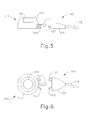
- FIG. 5 depicts a side view of an injection port with an exemplary locking connector
- FIG. 6 depicts a top view of the exemplary injection port shown in FIG. 5 ;
- FIG. 7 depicts a side view of another exemplary version of an injection port with a locking connector and cover
- FIG. 8 depicts a side view of the injection port shown in FIG. 7 with the locking connector engaging the injection port;
- FIG. 9 depicts a side view of the injection port shown in FIG. 7 with the locking connector engaging the injection port and the cover removed;
- FIG. 10 depicts a top perspective view of an exemplary injection port with locking members in an fully closed position
- FIG. 11 depicts a top perspective view of the injection port shown in FIG. 10 with the locking members removed to show a barbed stem;
- FIG. 12 depicts a top view of an exemplary injection port with a rotating disc in a closed position
- FIG. 13 depicts a top view of the injection port shown in FIG. 12 with the rotating disc in an open position
- FIG. 14 depicts a top view of an exemplary injection port having a hinge feature in a closed position
- FIG. 15 depicts a top view of the injection port of FIG. 14 with the hinge feature in an open position.
- FIGS. 1-4 illustrate an exemplary gastric band system (10).
- gastric band system (10) comprises an injection port (12), a gastric band (20), and a flexible conduit (or catheter) (18).
- Injection port (12) of the present example comprises a port housing (14), a needle penetrable septum (16) and a fluid reservoir (not shown in FIGS. 1-4 ) located beneath septum (16).
- a needle may pierce septum (16) to reach the reservoir and add or withdraw fluid (e.g., saline, etc.).
- Catheter (18) e.g., a flexible and/or resilient polymeric tube
- port housing (14) is attached to port housing (14) and is in fluid communication with the fluid reservoir therein.
- catheter (18) is slid over a barbed stem (not shown in FIGS. 1-4 ), which extends from port housing (14) and is in fluid communication with the fluid reservoir beneath septum (16).
- a retention sleeve (19) is slid over catheter (18) in the region near port housing (14), to squeeze catheter (18) against the barbed stem, such that retention sleeve (19) assists in keeping catheter (18) secured to the barbed stem.
- Port housing (14) may comprise a unitary structure (e.g., a one piece housing insert molded about septum (16), etc.). Alternatively, port housing (14) may be assembled from two or more mating components such as a port body that at least partially receives a port base therein. Port housing (14) may be formed of titanium, plastic, or any other suitable material or combination of materials. Septum (16) may be formed of silicone or any other suitable material or combination of materials.
- Injection port (12) may be subcutaneously secured over a patient's sternum, to the patient's abdominal fascia, or in any other suitable location.
- port (12) may be sutured in place using the suture apertures (15) located about the periphery of port housing (14).
- injection port (12) may be configured and operable in accordance with the teachings of U.S. Pub. No. 2005/0283118 , entitled “Implantable Medical Device with Simultaneous Attachment Mechanism and Method," published December 22, 2005, the disclosure of which is incorporated by reference herein.
- injection port (12) may be configured to include a plurality of fasteners that are selectively deployed from the injection port in order to secure the port in place within a patient, as further described in U.S. Pub. No. 2005/0283118 .
- injection port (12) may have any other suitable configuration and/or operability.
- Gastric band (20) of the present example comprises an inflatable bladder (22) that is secured to a flexible strap (24).
- Inflatable bladder (22) may be formed of silicone or any other suitable material or combination of materials.
- Catheter (18) provides fluid communication between bladder (22) and the reservoir of injection port (12).
- Catheter (18) may be formed of silicone or any other suitable material or combination of materials.
- catheter (18), bladder (22), and injection port (12) form a closed fluid circuit. Accordingly, a needle that is inserted through septum (16) into the underlying reservoir may be used to add fluid to or withdraw fluid from inflatable bladder (22) in order to adjust the restriction created by gastric band (20) as described in greater detail below.
- gastric band (20) is configured and operable in accordance with the teachings of U.S. Pat. No. 7,416,528 , entitled "Latching Device for Gastric Band," issued August 26, 2008, the disclosure of which is incorporated by reference herein.
- gastric band (20) may have any other suitable configuration and/or operability.
- gastric band (20) is applied about the gastro-esophageal junction of a patient.
- gastric band (20) is installed such that bladder (22) is adjacent to the tissue of the gastro-esophageal junction, with strap (24) on the outside of bladder (22).
- the ends of strap (24) are secured relative to each other when gastric band (20) is sufficiently wrapped about the patient's stomach (2).
- strap (24) is flexible in this example, strap (24) substantially resists stretching along its length. Accordingly, when fluid is added to bladder (22) (e.g., using a needle inserted through septum (16) of injection port (12), etc.), bladder (22) expands and exerts inward forces on the gastro-esophageal junction of the patient.
- an installed gastric band (20) at least substantially encloses the upper portion of stomach (2) near the junction with esophagus (4) in the present example.
- FIG. 3 shows gastric band (20) in a deflated configuration, where bladder (22) contains little to no fluid, thereby maximizing the size of the stoma opening into stomach (2).
- FIG. 4 shows gastric band (20) in an inflated, fluid-filled configuration, where bladder (22) contains substantially more fluid than is shown in FIG. 3 . In this configuration shown in FIG. 4 , the pressure of gastric band (20) against stomach (2) is increased due to the fluid within bladder (22), thereby decreasing the stoma opening to create a food intake restriction.
- FIG. 4 also schematically illustrates the dilation of esophagus (4) above gastric band (20) to form an upper pouch (6) beneath the diaphragm muscle (8) of the patient.
- catheter (18) may leak as fluid is being delivered from injection port (12) to gastric band (20).
- suture apertures (15) are used to suture injection port (12) into place within the patient.
- Various examples will be described below that relate to structures for preventing injection port (12) from being fully sutured in place until catheter (18) and the barbed stem are in fact sufficiently secured together. Other examples will be apparent to those of ordinary skill in the art in view of the teachings herein.
- FIG. 5 shows an exemplary locking connector (100) for use with catheter (118).
- Locking connector (100) comprises a sleeve body (104) and an engagement feature (102).
- Sleeve body (104) serves as a retention sleeve, similar to retention sleeve (19) discussed above, to assist in securing catheter (118) to barbed stem (127) of injection port (112).
- Septum (116) is held within housing (114) of injection port (112) and may be pierced with a needle to inject fluid through catheter (118) when locking connector (100) and catheter (118) are coupled with barbed stem (127) of injection port (112).
- Injection port (112) also defines suture apertures (115) through which sutures may be used to secure injection port (112) within a patient.
- engagement feature (102) defines complementary apertures (103), which are shaped and positioned to complement suture apertures (115).
- apertures (103) align with apertures (115) such that suture(s) may be guided through suture apertures (103, 115) into tissue.
- apertures (103, 115) are not fully aligned (e.g., if locking connector (100) is only partially pressed against injection port (112), etc.), suture(s) would not have a clear path to pass through apertures (115), which would be blocked by engagement feature (102). While the present example shows a pair of suture apertures (115) and complementary apertures (103), it will be appreciated that any suitable number of suture apertures (115) and complementary apertures (103) may be used as would be apparent to one of ordinary skill in the art in view of the teachings herein. It is also contemplated that the number of suture apertures (115) need not necessarily equal the number of complementary apertures (103). For example, suture apertures (115) may outnumber complementary apertures (103).
- a user may grasp locking connector (100) and press locking connector (100) against injection port (112) to establish a fluid tight connection between catheter (118) and injection port (112) by coupling catheter (118) and barbed stem (127).
- suture apertures (115) and complementary apertures (103) are aligned, the user may use that alignment as verification that locking connector (100) is properly connected with injection port (112) and that it is appropriate to pass sutures through suture apertures (115) to secure injection port (112) to the patient's tissue.
- a hinged member or other suitable member may block suture apertures (115) until locking connector (100) is fully engaged with injection port (112). Once fully engaged, the hinged member is rotated by locking connector (100) thereby moving aside to reveal suture apertures (115).
- catheter (118) may directly engage the hinged member to thereby move the hinged member to reveal suture apertures (115).
- a cover (230) may be used to verify that it is suitable to pass sutures through suture apertures (115).
- FIG. 7 shows injection port (212) comprising a housing (214) with a septum (216) contained therein.
- a barbed stem (227) extends from housing (214) and provides fluid communication with a reservoir (not shown) that is defined by housing (214) beneath septum (216).
- Injection port (212) also comprises suture apertures (215) and a cover (230) slidably mounted to the bottom of injection port (212).
- suture apertures (215) are formed through an annular flange (217) that extends outwardly from the bottom of housing (214).
- cover (230) is configured to block the bottoms of suture apertures (215) when cover (230) is fully engaged with housing (214), such that cover (230) prevents sutures from fully passing through flange (217) via suture apertures (215).
- Locking connector (200) comprises a sleeve body (204) that engages injection port (212) to secure catheter (218) to barbed stem (227), thereby establishing fluid communication between injection port (212) and catheter (218).
- Locking connector (200) further comprises engagement feature (202) operable to engage cover (230).
- engagement feature (202) is configured and positioned to push cover (230) along the bottom of housing (214) as locking connector (200) is pressed against injection port (212).
- FIG. 8 shows locking connector (200) engaging injection port (212) with engagement feature (202) pushing cover (230) out of its original position. In this distal, pushed position, cover (230) reveals a removal tab (232). The user may grasp removal tab (232) to simply remove cover (230) by pulling on removal tab (232) (e.g., using a conventional tissue grasping instrument, etc.).
- FIG. 9 shows injection port (212) after cover (230) has been removed. With cover (230) removed, suture apertures (215) are no longer blocked, allowing a user to pass suture(s) through suture apertures (215) to thereby secure injection port (212) to tissue in the patient.
- FIGS 10-11 show an exemplary injection port (312) having a housing (314) with a septum (316) contained therein and a pair of suture apertures (315) that are formed through housing (314).
- a barbed stem (327) extends from housing (314) and is in fluid communication with a reservoir beneath septum (316).
- Injection port (312) further comprises a pair of half locking members (304) that are pivotally coupled with injection port (312) via respective pins (305). Locking members (304) are moveable between and open position to a closed position as shown in FIG 10 .
- locking members (304) When catheter (318) is slid over barbed stem (327), locking members (304) may be pivoted to the closed position to cooperatingly clamp catheter (318) against barbed stem (327), thereby helping to secure catheter (318) to barbed stem (327).
- catheter (318) may be connected to injection port (312) followed by closing locking members (304) upon catheter (318).
- locking members (304) may comprise more than two pivoting jaws or a single member operable to lock catheter (318) into injection port (312).
- locking members (304) may be constructed in accordance with at least some of the teachings of U.S. Patent Application Serial No. 12/917,544 , entitled “Implantable Medical Port with Fluid Conduit Retention Sleeve,” filed on November 2, 2010, the disclosure of which is incorporated by reference herein.
- Locking members (304) further define a pair of complementary apertures (303) that complement suture apertures (315) formed in housing (314) of injection port (312).
- Complementary apertures (303) and suture apertures (315) are positioned such that complementary apertures (303) and suture apertures (315) are only aligned when locking members (304) are in the fully closed position as shown in FIG. 10 .
- sutures and/or guide needles may be passed through apertures (303, 315) to secure injection port (312) to tissue in a patient. If locking members (304) are not fully closed, apertures (303, 315) will not align and sutures will not be able to pass fully through apertures (303, 315).
- FIGS. 12-13 show an exemplary injection port (412) having a rotating disc (413) mounted on top of injection port (412), though it should be understood that disc (413) may alternatively be mounted to the bottom of injection port (412).
- Injection port (412) also has a barbed stem (427) extending from injection port (412), to interface with catheter (418) like other barbed stems described herein.
- Injection port (412) is in selective communication with locking connector (400), which leads to catheter (418).
- Locking connector (400) comprises a locking member (404) that is operable to directly engage injection port (412) to secure catheter (418) to barbed stem (427) in order to establish fluid communication between catheter (418) and injection port (412).
- Injection port (412) of the present example further comprises a septum (416) that is operable to receive a needle for providing fluid to catheter (418) via barbed stem (427).
- Disc (413) encircles septum (416) such that a needle may still be inserted into septum (416) even with disc (413) mounted on injection port (412).
- Disc (413) defines a plurality of disc openings (415), which form a circular pattern around the periphery of disc (413).
- any suitable arrangement for disc openings (415) may be used as would be apparent to one of ordinary skill in the art in view of the teachings herein.
- Disc openings (415) correspond to suture openings (417) that are formed in a lower annular flange of injection port (412).
- Disc (413) is rotatable between an open position and a closed position to selectively reveal suture openings (417) of injection port (412).
- disc openings (415) do not align with suture openings (417) of injection port (412).
- disc (413) covers suture openings (417) while the lower flange of injection port (412) blocks the bottoms of disc openings (415) such that sutures cannot fully pass through either openings (415) or openings (417).
- sutures cannot pass through disc openings (415, 417) to secure injection port (412) to tissue when disc (412) is in the closed position.
- disc (413) may be rotated as shown in FIG. 13 to reveal suture openings (417). Thereafter, sutures may pass fully through aligned openings (415, 417) to secure injection port (412) to tissue in a patient.
- locking member (404) is operable to engage a switch, trigger, or other feature within injection port (412) to toggle disc (413) between the open and closed positions.
- disc (413) may be resiliently biased to the closed position (e.g., by a ribbon spring, etc.), and features of injection port (412) and/or locking member (404) may transition disc (413) to the open position, against the resilient bias, upon locking member (404) being fully seated against injection port (412).
- simply engaging and securing the connection between locking member (404) and injection port (412) may be sufficient to switch disc (413) from open to closed and vice versa.
- engaging injection port (412) with locking member (404) may simply unlock disc (413) such that the user may manually turn disc (413) to either an open or closed state. It is also contemplated that injection port (412) may be configured such that disc (413) must be rotated in order to properly secure locking member (400) to injection port (412). In other words, if disc openings (415) and suture openings (417) are not aligned, then locking member (400) and injection port (412) cannot be properly secured. Other suitable ways of conditionally engaging locking member (400) with injection port (412) will be apparent to one of ordinary skill in the art in view of the teachings herein.
- FIGS. 14-15 show an exemplary injection port (512) having a pair of hinge features (504) pivotally mounted to a flange of housing (514) by respective pins (503).
- Injection port (512) also includes a septum (516) and a barbed stem (527), which is in fluid communication with a reservoir positioned under septum (516).
- Each hinge feature (504) is operable to transition between a closed position as shown in FIG. 14 and an open position as shown in FIG. 15 . In the closed position, hinge features (504) cover respective suture apertures (515). As a result, suture thread cannot be guided through suture apertures (515) when hinge features (504) are in a closed position as shown in FIG. 14 .
- hinge features (504) are engaged by catheter (518), which causes hinge features (504) to pivot about pins (503), thus moving hinge features (504) to the open position depicted in FIG. 15 .
- suture apertures (515) are revealed and sutures may be passed fully through suture apertures (515).
- hinge feature (504) While the present example shows catheter (518) and hinge feature (504) interacting directly, in some other versions, the engagement with hinge feature (504) may be indirect through, for example, a retention sleeve, a flange, or any other suitable component as would be apparent to one of ordinary skill in the art in view of the teachings herein.
- the injection ports described herein may be used as part of a gastric band system.
- a gastric band is positioned in a patient in the manner described previously, and an injection port of the type described herein also implanted in the patient.
- One end of a fluid conduit is attached to the injection port, such as by mounting one end of the conduit over the injection port stem, and then fitting the retention sleeve attached to the housing over at least a portion of the conduit mounted to the stem such that the flexible fingers in the retention sleeve help prevent the conduit from being pulled off of the stem.
- the other end of the conduit is coupled to the gastric band in order to provide fluid communication between the gastric band and the reservoir of the injection port.
- the conduit may be coupled to the injection port and/or the gastric band either before or after those structures are implanted in the patient.
- gastric band system (10) may include an implanted pump/reservoir system (not shown) instead of including an injection port (12).
- a pump/reservoir system may be controlled to selectively vary the amount of fluid in gastric band (20). Examples of such a system are described in U.S. Pat. No. 7,390,294 , entitled “Piezo Electrically Driven Bellows Infuser for Hydraulically Controlling an Adjustable Gastric Band,” issued June 24, 2008, the disclosure of which is incorporated by reference herein. Other examples of such a system are described in U.S. Pat. No.
- Such systems may include a catheter or other type of conduit coupling the pump/reservoir with gastric band (20). Accordingly, such systems may include any of the various suture opening alignment features described herein. Similarly, it should be understood that gastric band (20) may include any of the various suture opening alignment features described herein.
- gastric band (20) may include any of the various suture opening alignment features described herein.
- bands are used for the treatment of fecal incontinence.
- One such band is described in U.S. Pat. No. 6,461,292 , entitled “Anal Incontinence Treatment with Wireless Energy Supply,” issued October 8, 2002, the disclosure of which is incorporated by reference herein.
- Bands can also be used to treat urinary incontinence.
- One such band is described in U.S. Pat. No. 7,621,863 , entitled “Urinary Incontinence Treatment with Wireless Energy Supply,” issued November 24, 2009, the disclosure of which is incorporated by reference herein.
- Bands can also be used to treat heartburn and/or acid reflux.
- Versions of the present invention have application in conventional endoscopic and open surgical instrumentation as well as application in robotic-assisted surgery.
Abstract
Description
- Implantable medical devices may be implanted in a patient to perform a therapeutic function for that patient. Non-limiting examples of such devices include pace makers, access ports (such as vascular access ports, infusion ports, and ports used with gastric band systems, etc.) and gastric pacing devices. Such implants may need to be attached, perhaps subcutaneously, in an appropriate place in order to function properly. It may be desirable that the procedure to implant such devices be quick, easy and efficient.
- Ports may be placed beneath the skin of a body for injecting fluids into or withdrawing fluids from the body. By way of example, vascular access ports may be used for infusing medication, blood draws, and many other applications. Injection ports may be used for adding or withdrawing fluid in adjustable gastric band systems. These various access ports may include an implantable port housing coupled to a fluid conduit which delivers fluid to or withdraws fluid from a location in the patient's body (e.g., a vein or a gastric band, etc.).
- Gastric band systems are operable to restrict the flow of food from the esophagus into the stomach. Some gastric bands include a fluid-filled elastomeric bladder with fixed endpoints that encircles the stomach just inferior to the gastro-esophageal junction. When fluid is added to the bladder, the band expands against the stomach, creating a food intake restriction or stoma in the stomach. To decrease this restriction, fluid is removed from the bladder. Examples of gastric bands are disclosed in
U.S. Pat. No. 7,416,528 , entitled "Latching Device for Gastric Band," issued August 26, 2008, the disclosure of which is incorporated by reference herein. Another example of such an adjustable gastric band is disclosed inU.S. Pat. No. 6,067,991 , entitled "Mechanical Food Intake Restriction Device," issued May 30, 2000, the disclosure of which is incorporated by reference herein. - To the extent that an adjustable gastric band system includes an injection port configured to receive the needle of a syringe assembly in order to add or withdraw fluid to or from the gastric band, those of ordinary skill in the art will appreciate that it may be desirable in some settings to locate both the injection port and, more specifically, the center of the injection port (e.g., when the septum of the injection port is at the center of the injection port). Locating the approximate center of the injection port with some degree of accuracy may facilitate addition or withdrawal of fluid via the injection port to adjust the gastric band system. One example of a system and method for identifying the location of an injection port is disclosed in
U.S. Pub. No. 2006/0211914 , entitled "System and Method for Determining Implanted Device Positioning and Obtaining Pressure Data" published September 21, 2006, the disclosure of which is incorporated by reference herein. - Those of ordinary skill in the art will appreciate that it may be advantageous in certain circumstances to sense pressure, strain, and/or other parameters associated with operation of a gastric band device. In some settings, it may be desirable to obtain data indicative of the pressure of fluid in a gastric band. Various examples of methods and devices for obtaining pressure data and other types of data are disclosed in
U.S. Pub. No. 2006/0189888 , entitled "Device for Non-Invasive Measurement of Fluid Pressure in an Adjustable Restriction Device," published August 24, 2006, the disclosure of which is incorporated by reference herein. Additional examples of methods and devices for obtaining pressure data and other types of data are disclosed inU.S. Pub. No. 2006/0199997 , entitled "Monitoring of a Food Intake Restriction Device," published September 7, 2006, the disclosure of which is incorporated by reference herein. Such parameter data may be obtained before, during, and/or after adjustment of a gastric band, and may be useful for adjustment, diagnostic, monitoring, or other purposes, and may also be obtained with respect to a mechanically actuated gastric band. In settings where a fluid-filled gastric band is used, pressure data may be used to determine whether the amount of fluid in the gastric band needs to be adjusted; and/or for other purposes. - While a variety of implantable access ports and gastric band systems have been made and used, it is believed that no one prior to the inventor(s) has made or used an invention as described herein.
- The following is a non-exhaustive, numbered list of embodiments of the present invention that are or may be claimed.
- 1. An apparatus comprising:
- (a) a port operable to fluidly communicate with an implantable band, wherein the port comprises a needle penetrable septum, wherein the port further comprises at least one exterior aperture, wherein the at least one aperture extends through an exterior portion of the port;
- (b) a catheter in selective communication with the port, wherein the catheter is configured to establish fluid communication between the port and the implantable band, wherein the catheter is configured to deliver fluid from the port to the implantable band;
- (c) a sleeve in communication with the catheter, wherein the sleeve is configured to secure the catheter relative to the port; and
- (d) a blocking member configured to selectively block or unblock the at least one aperture in response to coupling of one or both of the sleeve or the catheter with the port.
- 2. The apparatus of embodiment 1, wherein the blocking member comprises at least one complementary aperture, wherein the complementary aperture has a shape complementary to the at least one aperture of the port.
- 3. The apparatus of
embodiment 2, wherein the complementary aperture and the at least one aperture are configured to align only when one or both of the sleeve or the catheter is secured to the port. - 4. The apparatus of embodiment 1, wherein the blocking member comprises a cover.
- 5. The apparatus of
embodiment 4, wherein the cover is slidably engaged with the port. - 6. The apparatus of embodiment 5, wherein the sleeve is configured to directly engage the cover, wherein the sleeve is operable to slidably urge the cover away from the port.
- 7. The apparatus of
embodiment 4, wherein the cover is configured to be removed only when one or both of the sleeve or the catheter is secured to the port. - 8. The apparatus of embodiment 1, wherein the at least one aperture is configured to be revealed only when one or both of the sleeve or the catheter is secured to the port.
- 9. The apparatus of embodiment 1, wherein the blocking member comprises a rotatable disc.
- 10. The apparatus of embodiment 9, wherein the rotatable disc is configured to rotate automatically upon one or both of the sleeve or the catheter establishing communication with the port.
- 11. The apparatus of embodiment 9, wherein the disc is movable between a locked position and an unlocked position, wherein one or both of the sleeve or the catheter is configured to move the disc to the unlocked position when the one or both of the sleeve or the catheter engages the port, wherein the disc is manually rotatable in the unlocked position.
- 12. The apparatus of embodiment 9, wherein one or both of the sleeve or the catheter is configured to trigger a feature operable to rotate the disc.
- 13. The apparatus of embodiment 1, wherein the blocking member is pivotally coupled with the port.
- 14. The apparatus of embodiment 1, wherein the sleeve comprises a pair of clamping members pivotally coupled with the port, wherein the sleeve is configured to close upon the catheter to secure the catheter to the port.
- 15. The apparatus of
embodiment 14, wherein the clamping members comprise at least one aperture, wherein the clamping members are configured to serve as the blocking member when the clamping members are in an open position, wherein the clamping members are configured to reveal the at least one aperture of the port via the at least one aperture of the clamping members when the clamping members are in the closed position. - 16. An apparatus comprising:
- (a) an implantable band;
- (b) a port in selective fluid communication with the implantable band, wherein the port is configured to receive a needle to deliver a fluid to the implantable band;
- (c) a locking feature in selective communication with the port, wherein the locking feature defines a first aperture; and
- (d) a second aperture in communication with the port, wherein the first aperture and the second aperture are complementarily shaped, wherein one or both of the first aperture or the second aperture is moveable between a first position and a second position, wherein the first aperture and the second aperture are not aligned in the first position, wherein the first aperture and the second aperture are aligned in the second position to form a passageway extending therethrough, wherein the locking feature is operable to move one or both of the first aperture or the second aperture from the first position to the second position upon engagement of the locking feature with the port.
- 17. The apparatus of
embodiment 16, wherein the locking feature comprises a cover slidably engaged with the port. - 18. The apparatus of
embodiment 16, wherein the locking feature comprises a rotating disc, wherein the first aperture extends through the rotating disc. - 19. The apparatus of
embodiment 16, wherein the port comprises a switch, wherein the locking feature is operable to engage the switch. - 20. A method of using a port, a locking member in selective communication with the port, and a catheter in communication with the locking member, wherein the port comprises at least one suture aperture, wherein the locking member comprises at least one locking aperture, the method comprising:
- (a) coupling the locking member with the port;
- (b) establishing fluid communication between the catheter and the port;
- (c) aligning the at least one suture aperture and the at least one locking aperture, wherein the act of aligning comprises positioning the at least one suture aperture over the at least one locking aperture such that the at least one suture aperture and the at least one locking aperture together form a passageway;
- (d) placing the port against tissue;
- (e) verifying that the at least one suture aperture and the at least one locking aperture are aligned; and
- (f) securing the port to a portion of tissue, wherein the act of securing the port to a portion of tissue comprises passing a suture through the passageway.
- While the specification concludes with claims which particularly point out and distinctly claim the invention, it is believed the present invention will be better understood from the following description of certain examples taken in conjunction with the accompanying drawings, in which like reference numerals identify the same elements and in which:
-
FIG. 1 depicts a perspective view of an implantable portion of an exemplary gastric band system, including an injection port having an integral fluid conduit retention sleeve; -
FIG. 2 depicts a perspective view of the gastric band ofFIG. 1 , showing the band positioned around the gastro-esophageal junction of a patient; -
FIG. 3 depicts a cross-sectional view of the gastric band ofFIG. 1 , showing the band positioned around the gastro-esophageal junction of a patient in a deflated configuration; -
FIG. 4 depicts a cross-sectional view of the gastric band ofFIG. 1 , showing the band positioned around the gastro-esophageal junction of a patient in an inflated configuration to create a food intake restriction; -
FIG. 5 depicts a side view of an injection port with an exemplary locking connector; -
FIG. 6 depicts a top view of the exemplary injection port shown inFIG. 5 ; -
FIG. 7 depicts a side view of another exemplary version of an injection port with a locking connector and cover; -
FIG. 8 depicts a side view of the injection port shown inFIG. 7 with the locking connector engaging the injection port; -
FIG. 9 depicts a side view of the injection port shown inFIG. 7 with the locking connector engaging the injection port and the cover removed; -
FIG. 10 depicts a top perspective view of an exemplary injection port with locking members in an fully closed position; -
FIG. 11 depicts a top perspective view of the injection port shown inFIG. 10 with the locking members removed to show a barbed stem; -
FIG. 12 depicts a top view of an exemplary injection port with a rotating disc in a closed position; -
FIG. 13 depicts a top view of the injection port shown inFIG. 12 with the rotating disc in an open position; -
FIG. 14 depicts a top view of an exemplary injection port having a hinge feature in a closed position; and -
FIG. 15 depicts a top view of the injection port ofFIG. 14 with the hinge feature in an open position. - The drawings are not intended to be limiting in any way, and it is contemplated that various embodiments of the invention may be carried out in a variety of other ways, including those not necessarily depicted in the drawings. The accompanying drawings incorporated in and forming a part of the specification illustrate several aspects of the present invention, and together with the description serve to explain the principles of the invention; it being understood, however, that this invention is not limited to the precise arrangements shown.
- The following description of certain examples of the invention should not be used to limit the scope of the present invention. Other examples, features, aspects, embodiments, and advantages of the invention will become apparent to those skilled in the art from the following description, which is by way of illustration, one of the best modes contemplated for carrying out the invention. As will be realized, the invention is capable of other different and obvious aspects, all without departing from the invention. For example, while various embodiments of ports having tissue in-growth promoting surfaces and/or features are depicted and described as being part of a gastric band system, the tissue in-growth surfaces and features may be employed with other types of implantable medical ports or other medical devices. Accordingly, the drawings and descriptions should be regarded as illustrative in nature and not restrictive.
- I. Exemplary Gastric Band System
-
FIGS. 1-4 illustrate an exemplary gastric band system (10). As shown, gastric band system (10) comprises an injection port (12), a gastric band (20), and a flexible conduit (or catheter) (18). Injection port (12) of the present example comprises a port housing (14), a needle penetrable septum (16) and a fluid reservoir (not shown inFIGS. 1-4 ) located beneath septum (16). A needle may pierce septum (16) to reach the reservoir and add or withdraw fluid (e.g., saline, etc.). Catheter (18) (e.g., a flexible and/or resilient polymeric tube) is attached to port housing (14) and is in fluid communication with the fluid reservoir therein. In particular, catheter (18) is slid over a barbed stem (not shown inFIGS. 1-4 ), which extends from port housing (14) and is in fluid communication with the fluid reservoir beneath septum (16). After catheter (18) is slid over the barbed stem, a retention sleeve (19) is slid over catheter (18) in the region near port housing (14), to squeeze catheter (18) against the barbed stem, such that retention sleeve (19) assists in keeping catheter (18) secured to the barbed stem. - Port housing (14) may comprise a unitary structure (e.g., a one piece housing insert molded about septum (16), etc.). Alternatively, port housing (14) may be assembled from two or more mating components such as a port body that at least partially receives a port base therein. Port housing (14) may be formed of titanium, plastic, or any other suitable material or combination of materials. Septum (16) may be formed of silicone or any other suitable material or combination of materials.
- Injection port (12) may be subcutaneously secured over a patient's sternum, to the patient's abdominal fascia, or in any other suitable location. By way of example, port (12) may be sutured in place using the suture apertures (15) located about the periphery of port housing (14). In some other versions, injection port (12) may be configured and operable in accordance with the teachings of
U.S. Pub. No. 2005/0283118 , entitled "Implantable Medical Device with Simultaneous Attachment Mechanism and Method," published December 22, 2005, the disclosure of which is incorporated by reference herein. For example, injection port (12) may be configured to include a plurality of fasteners that are selectively deployed from the injection port in order to secure the port in place within a patient, as further described inU.S. Pub. No. 2005/0283118 . Alternatively, injection port (12) may have any other suitable configuration and/or operability. - Gastric band (20) of the present example comprises an inflatable bladder (22) that is secured to a flexible strap (24). Inflatable bladder (22) may be formed of silicone or any other suitable material or combination of materials. Catheter (18) provides fluid communication between bladder (22) and the reservoir of injection port (12). Catheter (18) may be formed of silicone or any other suitable material or combination of materials. In the present example, catheter (18), bladder (22), and injection port (12) form a closed fluid circuit. Accordingly, a needle that is inserted through septum (16) into the underlying reservoir may be used to add fluid to or withdraw fluid from inflatable bladder (22) in order to adjust the restriction created by gastric band (20) as described in greater detail below. In some versions, gastric band (20) is configured and operable in accordance with the teachings of
U.S. Pat. No. 7,416,528 , entitled "Latching Device for Gastric Band," issued August 26, 2008, the disclosure of which is incorporated by reference herein. Alternatively, gastric band (20) may have any other suitable configuration and/or operability. - In some settings, gastric band (20) is applied about the gastro-esophageal junction of a patient. In particular, and as shown in
FIG. 2 , gastric band (20) is installed such that bladder (22) is adjacent to the tissue of the gastro-esophageal junction, with strap (24) on the outside of bladder (22). The ends of strap (24) are secured relative to each other when gastric band (20) is sufficiently wrapped about the patient's stomach (2). While strap (24) is flexible in this example, strap (24) substantially resists stretching along its length. Accordingly, when fluid is added to bladder (22) (e.g., using a needle inserted through septum (16) of injection port (12), etc.), bladder (22) expands and exerts inward forces on the gastro-esophageal junction of the patient. This reduces the size of the internal stoma at the gastro-esophageal junction, thereby creating a restriction on food intake into the patient's stomach (2). It should be understood that the size of this stoma may be decreased by adding more fluid to bladder (22) to create a greater degree of restriction; or increased by withdrawing fluid from bladder (22) to reduce the degree of restriction. - As shown in
FIGS. 2-4 , an installed gastric band (20) at least substantially encloses the upper portion of stomach (2) near the junction with esophagus (4) in the present example.FIG. 3 shows gastric band (20) in a deflated configuration, where bladder (22) contains little to no fluid, thereby maximizing the size of the stoma opening into stomach (2).FIG. 4 shows gastric band (20) in an inflated, fluid-filled configuration, where bladder (22) contains substantially more fluid than is shown inFIG. 3 . In this configuration shown inFIG. 4 , the pressure of gastric band (20) against stomach (2) is increased due to the fluid within bladder (22), thereby decreasing the stoma opening to create a food intake restriction.FIG. 4 also schematically illustrates the dilation of esophagus (4) above gastric band (20) to form an upper pouch (6) beneath the diaphragm muscle (8) of the patient. - It may be desirable to have a way of determining whether catheter (18) is properly coupled with the barbed stem of injection port (12). For example, in some instances, if catheter (18) is not properly secured over the barbed stem, catheter (18) may leak as fluid is being delivered from injection port (12) to gastric band (20). In examples described herein, suture apertures (15) are used to suture injection port (12) into place within the patient. Thus, it may be desirable to prevent injection port (12) from being fully sutured in place until catheter (18) and the barbed stem are in fact sufficiently secured together. Various examples will be described below that relate to structures for preventing injection port (12) from being fully sutured in place until catheter (18) and the barbed stem are in fact sufficiently secured together. Other examples will be apparent to those of ordinary skill in the art in view of the teachings herein.
- II. Exemplary Locking Connector with Suture Holes
-
FIG. 5 shows an exemplary locking connector (100) for use with catheter (118). Locking connector (100) comprises a sleeve body (104) and an engagement feature (102). Sleeve body (104) serves as a retention sleeve, similar to retention sleeve (19) discussed above, to assist in securing catheter (118) to barbed stem (127) of injection port (112). Septum (116) is held within housing (114) of injection port (112) and may be pierced with a needle to inject fluid through catheter (118) when locking connector (100) and catheter (118) are coupled with barbed stem (127) of injection port (112). - Injection port (112) also defines suture apertures (115) through which sutures may be used to secure injection port (112) within a patient. As shown in
FIG. 6 , engagement feature (102) defines complementary apertures (103), which are shaped and positioned to complement suture apertures (115). As a result, once locking connector (100) is fully pressed against injection port (112), apertures (103) align with apertures (115) such that suture(s) may be guided through suture apertures (103, 115) into tissue. However, when apertures (103, 115) are not fully aligned (e.g., if locking connector (100) is only partially pressed against injection port (112), etc.), suture(s) would not have a clear path to pass through apertures (115), which would be blocked by engagement feature (102). While the present example shows a pair of suture apertures (115) and complementary apertures (103), it will be appreciated that any suitable number of suture apertures (115) and complementary apertures (103) may be used as would be apparent to one of ordinary skill in the art in view of the teachings herein. It is also contemplated that the number of suture apertures (115) need not necessarily equal the number of complementary apertures (103). For example, suture apertures (115) may outnumber complementary apertures (103). - In an exemplary use, a user may grasp locking connector (100) and press locking connector (100) against injection port (112) to establish a fluid tight connection between catheter (118) and injection port (112) by coupling catheter (118) and barbed stem (127). Once suture apertures (115) and complementary apertures (103) are aligned, the user may use that alignment as verification that locking connector (100) is properly connected with injection port (112) and that it is appropriate to pass sutures through suture apertures (115) to secure injection port (112) to the patient's tissue.
- In some other exemplary versions, before complementary apertures (103) align with suture apertures (115), a hinged member or other suitable member may block suture apertures (115) until locking connector (100) is fully engaged with injection port (112). Once fully engaged, the hinged member is rotated by locking connector (100) thereby moving aside to reveal suture apertures (115). As yet another merely illustrative variation, catheter (118) may directly engage the hinged member to thereby move the hinged member to reveal suture apertures (115).
- III. Exemplary Safety Trigger for Suture Holes
- In some exemplary versions, as shown in
FIGS. 7-9 , a cover (230) may be used to verify that it is suitable to pass sutures through suture apertures (115). In particular,FIG. 7 shows injection port (212) comprising a housing (214) with a septum (216) contained therein. A barbed stem (227) extends from housing (214) and provides fluid communication with a reservoir (not shown) that is defined by housing (214) beneath septum (216). Injection port (212) also comprises suture apertures (215) and a cover (230) slidably mounted to the bottom of injection port (212). In the present example, suture apertures (215) are formed through an annular flange (217) that extends outwardly from the bottom of housing (214). As shown inFIG. 7 , cover (230) is configured to block the bottoms of suture apertures (215) when cover (230) is fully engaged with housing (214), such that cover (230) prevents sutures from fully passing through flange (217) via suture apertures (215). Locking connector (200) comprises a sleeve body (204) that engages injection port (212) to secure catheter (218) to barbed stem (227), thereby establishing fluid communication between injection port (212) and catheter (218). - Locking connector (200) further comprises engagement feature (202) operable to engage cover (230). In particular, engagement feature (202) is configured and positioned to push cover (230) along the bottom of housing (214) as locking connector (200) is pressed against injection port (212).
FIG. 8 shows locking connector (200) engaging injection port (212) with engagement feature (202) pushing cover (230) out of its original position. In this distal, pushed position, cover (230) reveals a removal tab (232). The user may grasp removal tab (232) to simply remove cover (230) by pulling on removal tab (232) (e.g., using a conventional tissue grasping instrument, etc.).FIG. 9 shows injection port (212) after cover (230) has been removed. With cover (230) removed, suture apertures (215) are no longer blocked, allowing a user to pass suture(s) through suture apertures (215) to thereby secure injection port (212) to tissue in the patient. - IV. Exemplary Injection Port with Locking Members
-
FIGS 10-11 show an exemplary injection port (312) having a housing (314) with a septum (316) contained therein and a pair of suture apertures (315) that are formed through housing (314). A barbed stem (327) extends from housing (314) and is in fluid communication with a reservoir beneath septum (316). Injection port (312) further comprises a pair of half locking members (304) that are pivotally coupled with injection port (312) via respective pins (305). Locking members (304) are moveable between and open position to a closed position as shown inFIG 10 . When catheter (318) is slid over barbed stem (327), locking members (304) may be pivoted to the closed position to cooperatingly clamp catheter (318) against barbed stem (327), thereby helping to secure catheter (318) to barbed stem (327). Thus, catheter (318) may be connected to injection port (312) followed by closing locking members (304) upon catheter (318). While the exemplary version shows locking members (304) having a pair of jaws, other suitable versions may be used as would be apparent to one of ordinary skill in the art. For example, locking members (304) may comprise more than two pivoting jaws or a single member operable to lock catheter (318) into injection port (312). By way of example only, locking members (304) may be constructed in accordance with at least some of the teachings ofU.S. Patent Application Serial No. 12/917,544 - Locking members (304) further define a pair of complementary apertures (303) that complement suture apertures (315) formed in housing (314) of injection port (312). Complementary apertures (303) and suture apertures (315) are positioned such that complementary apertures (303) and suture apertures (315) are only aligned when locking members (304) are in the fully closed position as shown in
FIG. 10 . When complementary apertures (303) and suture apertures (315) are aligned, then sutures and/or guide needles may be passed through apertures (303, 315) to secure injection port (312) to tissue in a patient. If locking members (304) are not fully closed, apertures (303, 315) will not align and sutures will not be able to pass fully through apertures (303, 315). When locking members (304) are in a fully closed position to provide a clear passageway through apertures (303, 315), the user can be reasonably certain that catheter (318) is properly coupled with injection port (312), such that a proper seal between catheter (318) and injection port (312) has been established, before suturing injection port (312) to tissue. - V. Exemplary Rotating Feature
-
FIGS. 12-13 show an exemplary injection port (412) having a rotating disc (413) mounted on top of injection port (412), though it should be understood that disc (413) may alternatively be mounted to the bottom of injection port (412). Injection port (412) also has a barbed stem (427) extending from injection port (412), to interface with catheter (418) like other barbed stems described herein. Injection port (412) is in selective communication with locking connector (400), which leads to catheter (418). Locking connector (400) comprises a locking member (404) that is operable to directly engage injection port (412) to secure catheter (418) to barbed stem (427) in order to establish fluid communication between catheter (418) and injection port (412). - Injection port (412) of the present example further comprises a septum (416) that is operable to receive a needle for providing fluid to catheter (418) via barbed stem (427). Disc (413) encircles septum (416) such that a needle may still be inserted into septum (416) even with disc (413) mounted on injection port (412). Disc (413) defines a plurality of disc openings (415), which form a circular pattern around the periphery of disc (413). However, any suitable arrangement for disc openings (415) may be used as would be apparent to one of ordinary skill in the art in view of the teachings herein. Disc openings (415) correspond to suture openings (417) that are formed in a lower annular flange of injection port (412). Disc (413) is rotatable between an open position and a closed position to selectively reveal suture openings (417) of injection port (412). When disc (413) is rotated to a closed position, as seen in
FIG. 12 , disc openings (415) do not align with suture openings (417) of injection port (412). Instead, disc (413) covers suture openings (417) while the lower flange of injection port (412) blocks the bottoms of disc openings (415) such that sutures cannot fully pass through either openings (415) or openings (417). As a result, sutures cannot pass through disc openings (415, 417) to secure injection port (412) to tissue when disc (412) is in the closed position. However, disc (413) may be rotated as shown inFIG. 13 to reveal suture openings (417). Thereafter, sutures may pass fully through aligned openings (415, 417) to secure injection port (412) to tissue in a patient. - In some versions, locking member (404) is operable to engage a switch, trigger, or other feature within injection port (412) to toggle disc (413) between the open and closed positions. For instance, disc (413) may be resiliently biased to the closed position (e.g., by a ribbon spring, etc.), and features of injection port (412) and/or locking member (404) may transition disc (413) to the open position, against the resilient bias, upon locking member (404) being fully seated against injection port (412). In some versions, simply engaging and securing the connection between locking member (404) and injection port (412) may be sufficient to switch disc (413) from open to closed and vice versa. In some other exemplary versions, engaging injection port (412) with locking member (404) may simply unlock disc (413) such that the user may manually turn disc (413) to either an open or closed state. It is also contemplated that injection port (412) may be configured such that disc (413) must be rotated in order to properly secure locking member (400) to injection port (412). In other words, if disc openings (415) and suture openings (417) are not aligned, then locking member (400) and injection port (412) cannot be properly secured. Other suitable ways of conditionally engaging locking member (400) with injection port (412) will be apparent to one of ordinary skill in the art in view of the teachings herein.
- VI. Exemplary Injection Port with Hinge Feature
-
FIGS. 14-15 show an exemplary injection port (512) having a pair of hinge features (504) pivotally mounted to a flange of housing (514) by respective pins (503). Injection port (512) also includes a septum (516) and a barbed stem (527), which is in fluid communication with a reservoir positioned under septum (516). Each hinge feature (504) is operable to transition between a closed position as shown inFIG. 14 and an open position as shown inFIG. 15 . In the closed position, hinge features (504) cover respective suture apertures (515). As a result, suture thread cannot be guided through suture apertures (515) when hinge features (504) are in a closed position as shown inFIG. 14 . When catheter (518) is pushed onto barbed stem (527) to establish fluid communication with injection port (512), hinge features (504) are engaged by catheter (518), which causes hinge features (504) to pivot about pins (503), thus moving hinge features (504) to the open position depicted inFIG. 15 . Once hinge features (504) are moved to the open position, suture apertures (515) are revealed and sutures may be passed fully through suture apertures (515). - While the present example shows catheter (518) and hinge feature (504) interacting directly, in some other versions, the engagement with hinge feature (504) may be indirect through, for example, a retention sleeve, a flange, or any other suitable component as would be apparent to one of ordinary skill in the art in view of the teachings herein.
- It should be understood that while the various examples described herein relate to the use of suture apertures and sutures to secure injection port (12) to a patient's tissue, the teachings herein may be readily applied to injection ports that are secured to a patient's tissue in various other ways. By way of example only, the teachings herein may be readily applied to injection ports that include integral fasteners, such as the injection ports disclosed in described in
U.S. Pub. No. 2005/0283118 , the disclosure of which is incorporated by reference herein. For instance, such injection ports may prevent the fasteners from being deployed until a catheter and/or retention sleeve, etc., is fully secured to the injection port. Various suitable ways in which the teachings herein may be combined with teachings ofU.S. Pub. No. 2005/0283118 will be apparent to those of ordinary skill in the art in view of the teachings herein. Similarly, other suitable variations will be apparent to one of ordinary skill in the art in view of the teachings herein. - As mentioned previously, the injection ports described herein may be used as part of a gastric band system. By way of example, a gastric band is positioned in a patient in the manner described previously, and an injection port of the type described herein also implanted in the patient. One end of a fluid conduit is attached to the injection port, such as by mounting one end of the conduit over the injection port stem, and then fitting the retention sleeve attached to the housing over at least a portion of the conduit mounted to the stem such that the flexible fingers in the retention sleeve help prevent the conduit from being pulled off of the stem. The other end of the conduit is coupled to the gastric band in order to provide fluid communication between the gastric band and the reservoir of the injection port. The conduit may be coupled to the injection port and/or the gastric band either before or after those structures are implanted in the patient.
- As yet another example, gastric band system (10) may include an implanted pump/reservoir system (not shown) instead of including an injection port (12). Such a pump/reservoir system may be controlled to selectively vary the amount of fluid in gastric band (20). Examples of such a system are described in
U.S. Pat. No. 7,390,294 , entitled "Piezo Electrically Driven Bellows Infuser for Hydraulically Controlling an Adjustable Gastric Band," issued June 24, 2008, the disclosure of which is incorporated by reference herein. Other examples of such a system are described inU.S. Pat. No. 7,351,240 , entitled "Thermodynamically Driven Reversible Infuser Pump for Use as a Remotely Controlled Gastric Band," issued April 1, 2008, the disclosure of which is incorporated by reference herein. Such systems may include a catheter or other type of conduit coupling the pump/reservoir with gastric band (20). Accordingly, such systems may include any of the various suture opening alignment features described herein. Similarly, it should be understood that gastric band (20) may include any of the various suture opening alignment features described herein. Various suitable ways in which the suture opening alignment features described herein may be incorporated into a pump/reservoir and/or into a gastric band (20) will be apparent to those of ordinary skill in the art in view of the teachings herein. - It should be understood from the foregoing that conduit/catheter retention features such as those described herein may be incorporated into virtually any type of implanted device. The above described examples of gastric band systems are mere illustrations. The inventors' contemplation is not limited to components of gastric band systems. By way of example only, conduit/catheter retention features may be incorporated into an implanted drug infusion port, chemotherapy port, or any other type of implantable port that is used to deliver medication. Still other types of implanted devices that may incorporate conduit/catheter retention features will be apparent to those of ordinary skill in the art in view of the teachings herein.
- It will become readily apparent to those skilled in the art that examples described herein may have applicability to other types of implantable bands. For example, bands are used for the treatment of fecal incontinence. One such band is described in
U.S. Pat. No. 6,461,292 , entitled "Anal Incontinence Treatment with Wireless Energy Supply," issued October 8, 2002, the disclosure of which is incorporated by reference herein. Bands can also be used to treat urinary incontinence. One such band is described inU.S. Pat. No. 7,621,863 , entitled "Urinary Incontinence Treatment with Wireless Energy Supply," issued November 24, 2009, the disclosure of which is incorporated by reference herein. Bands can also be used to treat heartburn and/or acid reflux. One such band is described inU.S. Pat. No. 6,470,892 , entitled "Mechanical Heartburn and Reflux Treatment," issued October 29, 2002, the disclosure of which is incorporated by reference herein. Bands can also be used to treat impotence. One such band is described inU.S. Pat. No. 7,442,165 , entitled "Penile Prosthesis," issued October 28, 2008, the disclosure of which is incorporated by reference herein. Various ways in which the teachings herein may be incorporated with the teachings of these patent references will be apparent to those of ordinary skill in the art. - Versions of the present invention have application in conventional endoscopic and open surgical instrumentation as well as application in robotic-assisted surgery.
- Having shown and described various embodiments of the present invention, further adaptations of the methods and systems described herein may be accomplished by appropriate modifications by one of ordinary skill in the art without departing from the scope of the present invention. Several of such potential modifications have been mentioned, and others will be apparent to those skilled in the art. For instance, the examples, embodiments, geometries, materials, dimensions, ratios, steps, and the like discussed above are illustrative and are not required. Accordingly, the scope of the present invention should be considered in terms of the following claims and is understood not to be limited to the details of structure and operation shown and described in the specification and drawings.
Claims (15)
- An apparatus comprising:(a) a port operable to fluidly communicate with an implantable band, wherein the port comprises a needle penetrable septum, wherein the port further comprises at least one exterior aperture, wherein the at least one aperture extends through an exterior portion of the port;(b) a catheter in selective communication with the port, wherein the catheter is configured to establish fluid communication between the port and the implantable band, wherein the catheter is configured to deliver fluid from the port to the implantable band;(c) a sleeve in communication with the catheter, wherein the sleeve is configured to secure the catheter relative to the port; and(d) a blocking member configured to selectively block or unblock the at least one aperture in response to coupling of one or both of the sleeve or the catheter with the port.
- The apparatus of claim 1, wherein the blocking member comprises at least one complementary aperture, wherein the complementary aperture has a shape complementary to the at least one aperture of the port.
- The apparatus of claim 2, wherein the complementary aperture and the at least one aperture are configured to align only when one or both of the sleeve or the catheter is secured to the port.
- The apparatus of claim 1, wherein the blocking member comprises a cover.
- The apparatus of claim 4, wherein the cover is slidably engaged with the port.
- The apparatus of claim 5, wherein the sleeve is configured to directly engage the cover, wherein the sleeve is operable to slidably urge the cover away from the port.
- The apparatus of claim 4, wherein the cover is configured to be removed only when one or both of the sleeve or the catheter is secured to the port.
- The apparatus of claim 1, wherein the at least one aperture is configured to be revealed only when one or both of the sleeve or the catheter is secured to the port.
- The apparatus of claim 1, wherein the blocking member comprises a rotatable disc.
- The apparatus of claim 9, wherein the rotatable disc is configured to rotate automatically upon one or both of the sleeve or the catheter establishing communication with the port.
- The apparatus of claim 9, wherein the disc is movable between a locked position and an unlocked position, wherein one or both of the sleeve or the catheter is configured to move the disc to the unlocked position when the one or both of the sleeve or the catheter engages the port, wherein the disc is manually rotatable in the unlocked position.
- The apparatus of claim 9, wherein one or both of the sleeve or the catheter is configured to trigger a feature operable to rotate the disc.
- The apparatus of claim 1, wherein the blocking member is pivotally coupled with the port.
- The apparatus of claim 1, wherein the sleeve comprises a pair of clamping members pivotally coupled with the port, wherein the sleeve is configured to close upon the catheter to secure the catheter to the port.
- The apparatus of claim 14, wherein the clamping members comprise at least one aperture, wherein the clamping members are configured to serve as the blocking member when the clamping members are in an open position, wherein the clamping members are configured to reveal the at least one aperture of the port via the at least one aperture of the clamping members when the clamping members are in the closed position.
Applications Claiming Priority (1)
| Application Number | Priority Date | Filing Date | Title |
|---|---|---|---|
| US13/215,270 US8936582B2 (en) | 2011-08-23 | 2011-08-23 | Implantable medical port with alignment feature |
Publications (2)
| Publication Number | Publication Date |
|---|---|
| EP2561899A1 true EP2561899A1 (en) | 2013-02-27 |
| EP2561899B1 EP2561899B1 (en) | 2016-12-14 |
Family
ID=46924228
Family Applications (1)
| Application Number | Title | Priority Date | Filing Date |
|---|---|---|---|
| EP12181528.6A Active EP2561899B1 (en) | 2011-08-23 | 2012-08-23 | Implantable medical port with alignment feature |
Country Status (3)
| Country | Link |
|---|---|
| US (1) | US8936582B2 (en) |
| EP (1) | EP2561899B1 (en) |
| AU (1) | AU2012211394B2 (en) |
Cited By (1)
| Publication number | Priority date | Publication date | Assignee | Title |
|---|---|---|---|---|
| WO2014177298A1 (en) * | 2013-05-03 | 2014-11-06 | Fresenius Kabi Deutschland Gmbh | Port for a catheter |
Families Citing this family (9)
| Publication number | Priority date | Publication date | Assignee | Title |
|---|---|---|---|---|
| US11173294B2 (en) * | 2013-03-15 | 2021-11-16 | Advanced Vascular Access Systems, LLC | Controlled arterial/venous access |
| CN103605324A (en) * | 2013-05-30 | 2014-02-26 | 湖北叶威智能科技有限公司 | Grain condition monitoring system used for grain bin |
| CN107072692B (en) | 2014-10-23 | 2020-03-24 | 柯惠Lp公司 | Method and apparatus for controlling surgical instruments using a surgical port assembly |
| USD791092S1 (en) * | 2015-03-30 | 2017-07-04 | Perouse Medical | Medical port |
| FR3051119A1 (en) * | 2016-05-10 | 2017-11-17 | Etic Systems | IMPLANTABLE DEVICES |
| USD816228S1 (en) | 2016-07-26 | 2018-04-24 | C. R. Bard, Inc. | Vascular access port stem |
| EP3934733A4 (en) * | 2019-03-03 | 2022-11-16 | Portal Access, Inc. | Subcutaneously changeable vascular access port |
| EP3996794A4 (en) * | 2019-07-09 | 2023-08-23 | Portal Access, Inc. | Toggling vascular access port |
| US11654260B1 (en) | 2021-11-04 | 2023-05-23 | Maho Med Tech, LLC | Ultrasound-placed pain management system and method with subcutaneous catheter |
Citations (16)
| Publication number | Priority date | Publication date | Assignee | Title |
|---|---|---|---|---|
| US4673394A (en) * | 1986-01-17 | 1987-06-16 | Strato Medical Corporation | Implantable treatment reservoir |
| US6067991A (en) | 1998-08-13 | 2000-05-30 | Forsell; Peter | Mechanical food intake restriction device |
| US6461292B1 (en) | 1999-08-12 | 2002-10-08 | Obtech Medical Ag | Anal incontinence treatment with wireless energy supply |
| US6470892B1 (en) | 2000-02-10 | 2002-10-29 | Obtech Medical Ag | Mechanical heartburn and reflux treatment |
| US20050283118A1 (en) | 2003-12-19 | 2005-12-22 | Joshua Uth | Implantable medical device with simulataneous attachment mechanism and method |
| US20060189888A1 (en) | 2005-02-24 | 2006-08-24 | Hassler William L Jr | Device for non-invasive measurement of fluid pressure in an adjustable restriction device |
| US20060211914A1 (en) | 2005-02-24 | 2006-09-21 | Hassler William L Jr | System and method for determining implanted device positioning and obtaining pressure data |
| US20070123831A1 (en) * | 2003-10-02 | 2007-05-31 | Hans Haindl | Port system |
| US7351240B2 (en) | 2004-05-28 | 2008-04-01 | Ethicon Endo—Srugery, Inc. | Thermodynamically driven reversible infuser pump for use as a remotely controlled gastric band |
| US7390294B2 (en) | 2004-05-28 | 2008-06-24 | Ethicon Endo-Surgery, Inc. | Piezo electrically driven bellows infuser for hydraulically controlling an adjustable gastric band |
| US7416528B2 (en) | 2005-07-15 | 2008-08-26 | Ethicon Endo-Surgery, Inc. | Latching device for gastric band |
| US7442165B2 (en) | 2000-02-14 | 2008-10-28 | Obtech Medical Ag | Penile prosthesis |
| US20090093765A1 (en) * | 2007-10-09 | 2009-04-09 | Glenn Bradley J | Enhanced stability implantable medical device |
| US7621863B2 (en) | 2000-02-10 | 2009-11-24 | Obtech Medical Ag | Urinary incontinence treatment with wireless energy supply |
| US20090306463A1 (en) * | 2006-01-16 | 2009-12-10 | Didier Philippe Mouton | Gastric Ring |
| US20100217198A1 (en) * | 2008-04-17 | 2010-08-26 | Allergan, Inc. | Implantable access port device having a safety cap |
Family Cites Families (2)
| Publication number | Priority date | Publication date | Assignee | Title |
|---|---|---|---|---|
| US5129891A (en) | 1989-05-19 | 1992-07-14 | Strato Medical Corporation | Catheter attachment device |
| US5178612A (en) * | 1990-10-10 | 1993-01-12 | Strato Medical Corporation | Compressible split cylinder bayonet locking device for attachment of a catheter to a fluid transfer device |
-
2011
- 2011-08-23 US US13/215,270 patent/US8936582B2/en not_active Expired - Fee Related
-
2012
- 2012-08-07 AU AU2012211394A patent/AU2012211394B2/en not_active Ceased
- 2012-08-23 EP EP12181528.6A patent/EP2561899B1/en active Active
Patent Citations (17)
| Publication number | Priority date | Publication date | Assignee | Title |
|---|---|---|---|---|
| US4673394A (en) * | 1986-01-17 | 1987-06-16 | Strato Medical Corporation | Implantable treatment reservoir |
| US6067991A (en) | 1998-08-13 | 2000-05-30 | Forsell; Peter | Mechanical food intake restriction device |
| US6461292B1 (en) | 1999-08-12 | 2002-10-08 | Obtech Medical Ag | Anal incontinence treatment with wireless energy supply |
| US6470892B1 (en) | 2000-02-10 | 2002-10-29 | Obtech Medical Ag | Mechanical heartburn and reflux treatment |
| US7621863B2 (en) | 2000-02-10 | 2009-11-24 | Obtech Medical Ag | Urinary incontinence treatment with wireless energy supply |
| US7442165B2 (en) | 2000-02-14 | 2008-10-28 | Obtech Medical Ag | Penile prosthesis |
| US20070123831A1 (en) * | 2003-10-02 | 2007-05-31 | Hans Haindl | Port system |
| US20050283118A1 (en) | 2003-12-19 | 2005-12-22 | Joshua Uth | Implantable medical device with simulataneous attachment mechanism and method |
| US7351240B2 (en) | 2004-05-28 | 2008-04-01 | Ethicon Endo—Srugery, Inc. | Thermodynamically driven reversible infuser pump for use as a remotely controlled gastric band |
| US7390294B2 (en) | 2004-05-28 | 2008-06-24 | Ethicon Endo-Surgery, Inc. | Piezo electrically driven bellows infuser for hydraulically controlling an adjustable gastric band |
| US20060211914A1 (en) | 2005-02-24 | 2006-09-21 | Hassler William L Jr | System and method for determining implanted device positioning and obtaining pressure data |
| US20060199997A1 (en) | 2005-02-24 | 2006-09-07 | Ethicon Endo-Surgery, Inc. | Monitoring of a food intake restriction device |
| US20060189888A1 (en) | 2005-02-24 | 2006-08-24 | Hassler William L Jr | Device for non-invasive measurement of fluid pressure in an adjustable restriction device |
| US7416528B2 (en) | 2005-07-15 | 2008-08-26 | Ethicon Endo-Surgery, Inc. | Latching device for gastric band |
| US20090306463A1 (en) * | 2006-01-16 | 2009-12-10 | Didier Philippe Mouton | Gastric Ring |
| US20090093765A1 (en) * | 2007-10-09 | 2009-04-09 | Glenn Bradley J | Enhanced stability implantable medical device |
| US20100217198A1 (en) * | 2008-04-17 | 2010-08-26 | Allergan, Inc. | Implantable access port device having a safety cap |
Cited By (4)
| Publication number | Priority date | Publication date | Assignee | Title |
|---|---|---|---|---|
| WO2014177298A1 (en) * | 2013-05-03 | 2014-11-06 | Fresenius Kabi Deutschland Gmbh | Port for a catheter |
| CN105163795A (en) * | 2013-05-03 | 2015-12-16 | 费森尤斯卡比德国有限公司 | Port for a catheter |
| US9555230B2 (en) | 2013-05-03 | 2017-01-31 | Fresenius Kabi Deutschland Gmbh | Port for a catheter |
| CN105163795B (en) * | 2013-05-03 | 2018-09-21 | 费森尤斯卡比德国有限公司 | Transfusion port for catheter |
Also Published As
| Publication number | Publication date |
|---|---|
| US8936582B2 (en) | 2015-01-20 |
| US20130053783A1 (en) | 2013-02-28 |
| EP2561899B1 (en) | 2016-12-14 |
| AU2012211394B2 (en) | 2014-09-18 |
| AU2012211394A1 (en) | 2013-03-14 |
Similar Documents
| Publication | Publication Date | Title |
|---|---|---|
| EP2561899B1 (en) | Implantable medical port with alignment feature | |
| US8480560B2 (en) | Implantable medical port with fluid conduit retention sleeve | |
| EP1547643B1 (en) | Subcutaneous self attaching injection port with integral fasteners | |
| JP5068489B2 (en) | Gastric band with matching end structure | |
| JP4959131B2 (en) | Flexible injection port | |
| EP1543861B1 (en) | Subcutaneous injection port for applied fasteners | |
| EP2327445B1 (en) | A surgically implantable injection port having an improved fastener | |
| US20050002984A1 (en) | Implantable band with attachment mechanism having dissimilar material properties | |
| AU2004235620A1 (en) | A method for implanting flexible injection port | |
| US8852217B2 (en) | Implantable injection port with tissue in-growth promoter | |
| JP2006263470A (en) | Hypodermoclysis port with fixed member | |
| MXPA04005756A (en) | Subcutaneous self attaching injection port with integral moveable retention members. | |
| JP2005103299A (en) | Implantable band having improved attachment mechanism | |
| US9022923B2 (en) | Implantable injection port with tissue in-growth promoter | |
| CA2846113A1 (en) | Implantable access port with mesh attachment rivets | |
| US9050446B2 (en) | Port with conduit wraparound feature | |
| US8663255B2 (en) | Gastric band with overmold |
Legal Events
| Date | Code | Title | Description |
|---|---|---|---|
| PUAI | Public reference made under article 153(3) epc to a published international application that has entered the european phase |
Free format text: ORIGINAL CODE: 0009012 |
|
| AK | Designated contracting states |
Kind code of ref document: A1 Designated state(s): AL AT BE BG CH CY CZ DE DK EE ES FI FR GB GR HR HU IE IS IT LI LT LU LV MC MK MT NL NO PL PT RO RS SE SI SK SM TR |
|
| AX | Request for extension of the european patent |
Extension state: BA ME |
|
| 17P | Request for examination filed |
Effective date: 20130827 |
|
| RBV | Designated contracting states (corrected) |
Designated state(s): AL AT BE BG CH CY CZ DE DK EE ES FI FR GB GR HR HU IE IS IT LI LT LU LV MC MK MT NL NO PL PT RO RS SE SI SK SM TR |
|
| 17Q | First examination report despatched |
Effective date: 20150304 |
|
| RIC1 | Information provided on ipc code assigned before grant |
Ipc: A61M 39/12 20060101ALN20160519BHEP Ipc: A61M 39/10 20060101ALI20160519BHEP Ipc: A61M 39/02 20060101AFI20160519BHEP |
|
| GRAP | Despatch of communication of intention to grant a patent |
Free format text: ORIGINAL CODE: EPIDOSNIGR1 |
|
| RIC1 | Information provided on ipc code assigned before grant |
Ipc: A61M 39/12 20060101ALN20160602BHEP Ipc: A61M 39/02 20060101AFI20160602BHEP Ipc: A61M 39/10 20060101ALI20160602BHEP |
|
| INTG | Intention to grant announced |
Effective date: 20160629 |
|
| RIC1 | Information provided on ipc code assigned before grant |
Ipc: A61M 39/02 20060101AFI20160617BHEP Ipc: A61M 39/12 20060101ALN20160617BHEP Ipc: A61M 39/10 20060101ALI20160617BHEP |
|
| RIN1 | Information on inventor provided before grant (corrected) |
Inventor name: TORAIN, STEPHEN M. Inventor name: SZWEDA, GINA M. Inventor name: WOODRUFF, SCOTT A. |
|
| GRAJ | Information related to disapproval of communication of intention to grant by the applicant or resumption of examination proceedings by the epo deleted |
Free format text: ORIGINAL CODE: EPIDOSDIGR1 |
|
| GRAR | Information related to intention to grant a patent recorded |
Free format text: ORIGINAL CODE: EPIDOSNIGR71 |
|
| GRAS | Grant fee paid |
Free format text: ORIGINAL CODE: EPIDOSNIGR3 |
|
| INTC | Intention to grant announced (deleted) | ||
| GRAA | (expected) grant |
Free format text: ORIGINAL CODE: 0009210 |
|
| RIC1 | Information provided on ipc code assigned before grant |
Ipc: A61M 39/10 20060101ALI20161007BHEP Ipc: A61M 39/02 20060101AFI20161007BHEP Ipc: A61M 39/12 20060101ALN20161007BHEP |
|
| INTG | Intention to grant announced |
Effective date: 20161103 |
|
| AK | Designated contracting states |
Kind code of ref document: B1 Designated state(s): AL AT BE BG CH CY CZ DE DK EE ES FI FR GB GR HR HU IE IS IT LI LT LU LV MC MK MT NL NO PL PT RO RS SE SI SK SM TR |
|
| REG | Reference to a national code |
Ref country code: GB Ref legal event code: FG4D |
|
| REG | Reference to a national code |
Ref country code: CH Ref legal event code: EP |
|
| REG | Reference to a national code |
Ref country code: IE Ref legal event code: FG4D |
|
| REG | Reference to a national code |
Ref country code: AT Ref legal event code: REF Ref document number: 853022 Country of ref document: AT Kind code of ref document: T Effective date: 20170115 |
|
| REG | Reference to a national code |
Ref country code: DE Ref legal event code: R096 Ref document number: 602012026530 Country of ref document: DE |
|
| PG25 | Lapsed in a contracting state [announced via postgrant information from national office to epo] |
Ref country code: LV Free format text: LAPSE BECAUSE OF FAILURE TO SUBMIT A TRANSLATION OF THE DESCRIPTION OR TO PAY THE FEE WITHIN THE PRESCRIBED TIME-LIMIT Effective date: 20161214 |
|
| REG | Reference to a national code |
Ref country code: LT Ref legal event code: MG4D |
|
| REG | Reference to a national code |
Ref country code: NL Ref legal event code: MP Effective date: 20161214 |
|
| PG25 | Lapsed in a contracting state [announced via postgrant information from national office to epo] |
Ref country code: SE Free format text: LAPSE BECAUSE OF FAILURE TO SUBMIT A TRANSLATION OF THE DESCRIPTION OR TO PAY THE FEE WITHIN THE PRESCRIBED TIME-LIMIT Effective date: 20161214 Ref country code: LT Free format text: LAPSE BECAUSE OF FAILURE TO SUBMIT A TRANSLATION OF THE DESCRIPTION OR TO PAY THE FEE WITHIN THE PRESCRIBED TIME-LIMIT Effective date: 20161214 Ref country code: GR Free format text: LAPSE BECAUSE OF FAILURE TO SUBMIT A TRANSLATION OF THE DESCRIPTION OR TO PAY THE FEE WITHIN THE PRESCRIBED TIME-LIMIT Effective date: 20170315 Ref country code: NO Free format text: LAPSE BECAUSE OF FAILURE TO SUBMIT A TRANSLATION OF THE DESCRIPTION OR TO PAY THE FEE WITHIN THE PRESCRIBED TIME-LIMIT Effective date: 20170314 |
|
| REG | Reference to a national code |
Ref country code: AT Ref legal event code: MK05 Ref document number: 853022 Country of ref document: AT Kind code of ref document: T Effective date: 20161214 |
|
| PG25 | Lapsed in a contracting state [announced via postgrant information from national office to epo] |
Ref country code: FI Free format text: LAPSE BECAUSE OF FAILURE TO SUBMIT A TRANSLATION OF THE DESCRIPTION OR TO PAY THE FEE WITHIN THE PRESCRIBED TIME-LIMIT Effective date: 20161214 Ref country code: RS Free format text: LAPSE BECAUSE OF FAILURE TO SUBMIT A TRANSLATION OF THE DESCRIPTION OR TO PAY THE FEE WITHIN THE PRESCRIBED TIME-LIMIT Effective date: 20161214 Ref country code: HR Free format text: LAPSE BECAUSE OF FAILURE TO SUBMIT A TRANSLATION OF THE DESCRIPTION OR TO PAY THE FEE WITHIN THE PRESCRIBED TIME-LIMIT Effective date: 20161214 |
|
| PG25 | Lapsed in a contracting state [announced via postgrant information from national office to epo] |
Ref country code: NL Free format text: LAPSE BECAUSE OF FAILURE TO SUBMIT A TRANSLATION OF THE DESCRIPTION OR TO PAY THE FEE WITHIN THE PRESCRIBED TIME-LIMIT Effective date: 20161214 |
|
| REG | Reference to a national code |
Ref country code: FR Ref legal event code: PLFP Year of fee payment: 6 |
|
| PG25 | Lapsed in a contracting state [announced via postgrant information from national office to epo] |
Ref country code: RO Free format text: LAPSE BECAUSE OF FAILURE TO SUBMIT A TRANSLATION OF THE DESCRIPTION OR TO PAY THE FEE WITHIN THE PRESCRIBED TIME-LIMIT Effective date: 20161214 Ref country code: SK Free format text: LAPSE BECAUSE OF FAILURE TO SUBMIT A TRANSLATION OF THE DESCRIPTION OR TO PAY THE FEE WITHIN THE PRESCRIBED TIME-LIMIT Effective date: 20161214 Ref country code: IS Free format text: LAPSE BECAUSE OF FAILURE TO SUBMIT A TRANSLATION OF THE DESCRIPTION OR TO PAY THE FEE WITHIN THE PRESCRIBED TIME-LIMIT Effective date: 20170414 Ref country code: CZ Free format text: LAPSE BECAUSE OF FAILURE TO SUBMIT A TRANSLATION OF THE DESCRIPTION OR TO PAY THE FEE WITHIN THE PRESCRIBED TIME-LIMIT Effective date: 20161214 Ref country code: EE Free format text: LAPSE BECAUSE OF FAILURE TO SUBMIT A TRANSLATION OF THE DESCRIPTION OR TO PAY THE FEE WITHIN THE PRESCRIBED TIME-LIMIT Effective date: 20161214 |
|
| PG25 | Lapsed in a contracting state [announced via postgrant information from national office to epo] |
Ref country code: ES Free format text: LAPSE BECAUSE OF FAILURE TO SUBMIT A TRANSLATION OF THE DESCRIPTION OR TO PAY THE FEE WITHIN THE PRESCRIBED TIME-LIMIT Effective date: 20161214 Ref country code: BE Free format text: LAPSE BECAUSE OF FAILURE TO SUBMIT A TRANSLATION OF THE DESCRIPTION OR TO PAY THE FEE WITHIN THE PRESCRIBED TIME-LIMIT Effective date: 20161214 Ref country code: PL Free format text: LAPSE BECAUSE OF FAILURE TO SUBMIT A TRANSLATION OF THE DESCRIPTION OR TO PAY THE FEE WITHIN THE PRESCRIBED TIME-LIMIT Effective date: 20161214 Ref country code: AT Free format text: LAPSE BECAUSE OF FAILURE TO SUBMIT A TRANSLATION OF THE DESCRIPTION OR TO PAY THE FEE WITHIN THE PRESCRIBED TIME-LIMIT Effective date: 20161214 Ref country code: PT Free format text: LAPSE BECAUSE OF FAILURE TO SUBMIT A TRANSLATION OF THE DESCRIPTION OR TO PAY THE FEE WITHIN THE PRESCRIBED TIME-LIMIT Effective date: 20170414 Ref country code: IT Free format text: LAPSE BECAUSE OF FAILURE TO SUBMIT A TRANSLATION OF THE DESCRIPTION OR TO PAY THE FEE WITHIN THE PRESCRIBED TIME-LIMIT Effective date: 20161214 Ref country code: BG Free format text: LAPSE BECAUSE OF FAILURE TO SUBMIT A TRANSLATION OF THE DESCRIPTION OR TO PAY THE FEE WITHIN THE PRESCRIBED TIME-LIMIT Effective date: 20170314 Ref country code: SM Free format text: LAPSE BECAUSE OF FAILURE TO SUBMIT A TRANSLATION OF THE DESCRIPTION OR TO PAY THE FEE WITHIN THE PRESCRIBED TIME-LIMIT Effective date: 20161214 |
|
| REG | Reference to a national code |
Ref country code: DE Ref legal event code: R097 Ref document number: 602012026530 Country of ref document: DE |
|
| PLBE | No opposition filed within time limit |
Free format text: ORIGINAL CODE: 0009261 |
|
| STAA | Information on the status of an ep patent application or granted ep patent |
Free format text: STATUS: NO OPPOSITION FILED WITHIN TIME LIMIT |
|
| 26N | No opposition filed |
Effective date: 20170915 |
|
| PG25 | Lapsed in a contracting state [announced via postgrant information from national office to epo] |
Ref country code: DK Free format text: LAPSE BECAUSE OF FAILURE TO SUBMIT A TRANSLATION OF THE DESCRIPTION OR TO PAY THE FEE WITHIN THE PRESCRIBED TIME-LIMIT Effective date: 20161214 |
|
| PG25 | Lapsed in a contracting state [announced via postgrant information from national office to epo] |
Ref country code: SI Free format text: LAPSE BECAUSE OF FAILURE TO SUBMIT A TRANSLATION OF THE DESCRIPTION OR TO PAY THE FEE WITHIN THE PRESCRIBED TIME-LIMIT Effective date: 20161214 |
|
| REG | Reference to a national code |
Ref country code: CH Ref legal event code: PL |
|
| PG25 | Lapsed in a contracting state [announced via postgrant information from national office to epo] |
Ref country code: MC Free format text: LAPSE BECAUSE OF FAILURE TO SUBMIT A TRANSLATION OF THE DESCRIPTION OR TO PAY THE FEE WITHIN THE PRESCRIBED TIME-LIMIT Effective date: 20161214 |
|
| PG25 | Lapsed in a contracting state [announced via postgrant information from national office to epo] |
Ref country code: LI Free format text: LAPSE BECAUSE OF NON-PAYMENT OF DUE FEES Effective date: 20170831 Ref country code: CH Free format text: LAPSE BECAUSE OF NON-PAYMENT OF DUE FEES Effective date: 20170831 |
|
| REG | Reference to a national code |
Ref country code: IE Ref legal event code: MM4A |
|
| PG25 | Lapsed in a contracting state [announced via postgrant information from national office to epo] |
Ref country code: LU Free format text: LAPSE BECAUSE OF NON-PAYMENT OF DUE FEES Effective date: 20170823 |
|
| REG | Reference to a national code |
Ref country code: FR Ref legal event code: PLFP Year of fee payment: 7 |
|
| PG25 | Lapsed in a contracting state [announced via postgrant information from national office to epo] |
Ref country code: IE Free format text: LAPSE BECAUSE OF NON-PAYMENT OF DUE FEES Effective date: 20170823 |
|
| PG25 | Lapsed in a contracting state [announced via postgrant information from national office to epo] |
Ref country code: MT Free format text: LAPSE BECAUSE OF NON-PAYMENT OF DUE FEES Effective date: 20170823 |
|
| PG25 | Lapsed in a contracting state [announced via postgrant information from national office to epo] |
Ref country code: HU Free format text: LAPSE BECAUSE OF FAILURE TO SUBMIT A TRANSLATION OF THE DESCRIPTION OR TO PAY THE FEE WITHIN THE PRESCRIBED TIME-LIMIT; INVALID AB INITIO Effective date: 20120823 |
|
| PG25 | Lapsed in a contracting state [announced via postgrant information from national office to epo] |
Ref country code: CY Free format text: LAPSE BECAUSE OF NON-PAYMENT OF DUE FEES Effective date: 20161214 |
|
| PG25 | Lapsed in a contracting state [announced via postgrant information from national office to epo] |
Ref country code: MK Free format text: LAPSE BECAUSE OF FAILURE TO SUBMIT A TRANSLATION OF THE DESCRIPTION OR TO PAY THE FEE WITHIN THE PRESCRIBED TIME-LIMIT Effective date: 20161214 |
|
| PG25 | Lapsed in a contracting state [announced via postgrant information from national office to epo] |
Ref country code: TR Free format text: LAPSE BECAUSE OF FAILURE TO SUBMIT A TRANSLATION OF THE DESCRIPTION OR TO PAY THE FEE WITHIN THE PRESCRIBED TIME-LIMIT Effective date: 20161214 |
|
| PG25 | Lapsed in a contracting state [announced via postgrant information from national office to epo] |
Ref country code: AL Free format text: LAPSE BECAUSE OF FAILURE TO SUBMIT A TRANSLATION OF THE DESCRIPTION OR TO PAY THE FEE WITHIN THE PRESCRIBED TIME-LIMIT Effective date: 20161214 |
|
| PGFP | Annual fee paid to national office [announced via postgrant information from national office to epo] |
Ref country code: GB Payment date: 20230629 Year of fee payment: 12 |
|
| PGFP | Annual fee paid to national office [announced via postgrant information from national office to epo] |
Ref country code: FR Payment date: 20230703 Year of fee payment: 12 Ref country code: DE Payment date: 20230703 Year of fee payment: 12 |