EP2570812A2 - Droplet actuator devices and methods employing magnetic beads - Google Patents
Droplet actuator devices and methods employing magnetic beads Download PDFInfo
- Publication number
- EP2570812A2 EP2570812A2 EP12191032A EP12191032A EP2570812A2 EP 2570812 A2 EP2570812 A2 EP 2570812A2 EP 12191032 A EP12191032 A EP 12191032A EP 12191032 A EP12191032 A EP 12191032A EP 2570812 A2 EP2570812 A2 EP 2570812A2
- Authority
- EP
- European Patent Office
- Prior art keywords
- droplet
- magnet
- magnet assembly
- beads
- substrate
- Prior art date
- Legal status (The legal status is an assumption and is not a legal conclusion. Google has not performed a legal analysis and makes no representation as to the accuracy of the status listed.)
- Granted
Links
Images


Classifications
-
- G—PHYSICS
- G01—MEASURING; TESTING
- G01N—INVESTIGATING OR ANALYSING MATERIALS BY DETERMINING THEIR CHEMICAL OR PHYSICAL PROPERTIES
- G01N33/00—Investigating or analysing materials by specific methods not covered by groups G01N1/00 - G01N31/00
- G01N33/48—Biological material, e.g. blood, urine; Haemocytometers
- G01N33/50—Chemical analysis of biological material, e.g. blood, urine; Testing involving biospecific ligand binding methods; Immunological testing
- G01N33/53—Immunoassay; Biospecific binding assay; Materials therefor
- G01N33/543—Immunoassay; Biospecific binding assay; Materials therefor with an insoluble carrier for immobilising immunochemicals
- G01N33/54313—Immunoassay; Biospecific binding assay; Materials therefor with an insoluble carrier for immobilising immunochemicals the carrier being characterised by its particulate form
- G01N33/54326—Magnetic particles
-
- G—PHYSICS
- G01—MEASURING; TESTING
- G01N—INVESTIGATING OR ANALYSING MATERIALS BY DETERMINING THEIR CHEMICAL OR PHYSICAL PROPERTIES
- G01N33/00—Investigating or analysing materials by specific methods not covered by groups G01N1/00 - G01N31/00
- G01N33/48—Biological material, e.g. blood, urine; Haemocytometers
- G01N33/50—Chemical analysis of biological material, e.g. blood, urine; Testing involving biospecific ligand binding methods; Immunological testing
- G01N33/53—Immunoassay; Biospecific binding assay; Materials therefor
- G01N33/543—Immunoassay; Biospecific binding assay; Materials therefor with an insoluble carrier for immobilising immunochemicals
-
- B—PERFORMING OPERATIONS; TRANSPORTING
- B01—PHYSICAL OR CHEMICAL PROCESSES OR APPARATUS IN GENERAL
- B01L—CHEMICAL OR PHYSICAL LABORATORY APPARATUS FOR GENERAL USE
- B01L3/00—Containers or dishes for laboratory use, e.g. laboratory glassware; Droppers
-
- B—PERFORMING OPERATIONS; TRANSPORTING
- B01—PHYSICAL OR CHEMICAL PROCESSES OR APPARATUS IN GENERAL
- B01L—CHEMICAL OR PHYSICAL LABORATORY APPARATUS FOR GENERAL USE
- B01L3/00—Containers or dishes for laboratory use, e.g. laboratory glassware; Droppers
- B01L3/50—Containers for the purpose of retaining a material to be analysed, e.g. test tubes
- B01L3/502—Containers for the purpose of retaining a material to be analysed, e.g. test tubes with fluid transport, e.g. in multi-compartment structures
- B01L3/5027—Containers for the purpose of retaining a material to be analysed, e.g. test tubes with fluid transport, e.g. in multi-compartment structures by integrated microfluidic structures, i.e. dimensions of channels and chambers are such that surface tension forces are important, e.g. lab-on-a-chip
- B01L3/502715—Containers for the purpose of retaining a material to be analysed, e.g. test tubes with fluid transport, e.g. in multi-compartment structures by integrated microfluidic structures, i.e. dimensions of channels and chambers are such that surface tension forces are important, e.g. lab-on-a-chip characterised by interfacing components, e.g. fluidic, electrical, optical or mechanical interfaces
-
- B—PERFORMING OPERATIONS; TRANSPORTING
- B01—PHYSICAL OR CHEMICAL PROCESSES OR APPARATUS IN GENERAL
- B01L—CHEMICAL OR PHYSICAL LABORATORY APPARATUS FOR GENERAL USE
- B01L3/00—Containers or dishes for laboratory use, e.g. laboratory glassware; Droppers
- B01L3/50—Containers for the purpose of retaining a material to be analysed, e.g. test tubes
- B01L3/502—Containers for the purpose of retaining a material to be analysed, e.g. test tubes with fluid transport, e.g. in multi-compartment structures
- B01L3/5027—Containers for the purpose of retaining a material to be analysed, e.g. test tubes with fluid transport, e.g. in multi-compartment structures by integrated microfluidic structures, i.e. dimensions of channels and chambers are such that surface tension forces are important, e.g. lab-on-a-chip
- B01L3/50273—Containers for the purpose of retaining a material to be analysed, e.g. test tubes with fluid transport, e.g. in multi-compartment structures by integrated microfluidic structures, i.e. dimensions of channels and chambers are such that surface tension forces are important, e.g. lab-on-a-chip characterised by the means or forces applied to move the fluids
-
- B—PERFORMING OPERATIONS; TRANSPORTING
- B01—PHYSICAL OR CHEMICAL PROCESSES OR APPARATUS IN GENERAL
- B01L—CHEMICAL OR PHYSICAL LABORATORY APPARATUS FOR GENERAL USE
- B01L3/00—Containers or dishes for laboratory use, e.g. laboratory glassware; Droppers
- B01L3/50—Containers for the purpose of retaining a material to be analysed, e.g. test tubes
- B01L3/502—Containers for the purpose of retaining a material to be analysed, e.g. test tubes with fluid transport, e.g. in multi-compartment structures
- B01L3/5027—Containers for the purpose of retaining a material to be analysed, e.g. test tubes with fluid transport, e.g. in multi-compartment structures by integrated microfluidic structures, i.e. dimensions of channels and chambers are such that surface tension forces are important, e.g. lab-on-a-chip
- B01L3/502761—Containers for the purpose of retaining a material to be analysed, e.g. test tubes with fluid transport, e.g. in multi-compartment structures by integrated microfluidic structures, i.e. dimensions of channels and chambers are such that surface tension forces are important, e.g. lab-on-a-chip specially adapted for handling suspended solids or molecules independently from the bulk fluid flow, e.g. for trapping or sorting beads, for physically stretching molecules
-
- B—PERFORMING OPERATIONS; TRANSPORTING
- B01—PHYSICAL OR CHEMICAL PROCESSES OR APPARATUS IN GENERAL
- B01L—CHEMICAL OR PHYSICAL LABORATORY APPARATUS FOR GENERAL USE
- B01L3/00—Containers or dishes for laboratory use, e.g. laboratory glassware; Droppers
- B01L3/50—Containers for the purpose of retaining a material to be analysed, e.g. test tubes
- B01L3/502—Containers for the purpose of retaining a material to be analysed, e.g. test tubes with fluid transport, e.g. in multi-compartment structures
- B01L3/5027—Containers for the purpose of retaining a material to be analysed, e.g. test tubes with fluid transport, e.g. in multi-compartment structures by integrated microfluidic structures, i.e. dimensions of channels and chambers are such that surface tension forces are important, e.g. lab-on-a-chip
- B01L3/502769—Containers for the purpose of retaining a material to be analysed, e.g. test tubes with fluid transport, e.g. in multi-compartment structures by integrated microfluidic structures, i.e. dimensions of channels and chambers are such that surface tension forces are important, e.g. lab-on-a-chip characterised by multiphase flow arrangements
- B01L3/502784—Containers for the purpose of retaining a material to be analysed, e.g. test tubes with fluid transport, e.g. in multi-compartment structures by integrated microfluidic structures, i.e. dimensions of channels and chambers are such that surface tension forces are important, e.g. lab-on-a-chip characterised by multiphase flow arrangements specially adapted for droplet or plug flow, e.g. digital microfluidics
-
- C—CHEMISTRY; METALLURGY
- C12—BIOCHEMISTRY; BEER; SPIRITS; WINE; VINEGAR; MICROBIOLOGY; ENZYMOLOGY; MUTATION OR GENETIC ENGINEERING
- C12M—APPARATUS FOR ENZYMOLOGY OR MICROBIOLOGY; APPARATUS FOR CULTURING MICROORGANISMS FOR PRODUCING BIOMASS, FOR GROWING CELLS OR FOR OBTAINING FERMENTATION OR METABOLIC PRODUCTS, i.e. BIOREACTORS OR FERMENTERS
- C12M25/00—Means for supporting, enclosing or fixing the microorganisms, e.g. immunocoatings
- C12M25/01—Drops
-
- C—CHEMISTRY; METALLURGY
- C12—BIOCHEMISTRY; BEER; SPIRITS; WINE; VINEGAR; MICROBIOLOGY; ENZYMOLOGY; MUTATION OR GENETIC ENGINEERING
- C12M—APPARATUS FOR ENZYMOLOGY OR MICROBIOLOGY; APPARATUS FOR CULTURING MICROORGANISMS FOR PRODUCING BIOMASS, FOR GROWING CELLS OR FOR OBTAINING FERMENTATION OR METABOLIC PRODUCTS, i.e. BIOREACTORS OR FERMENTERS
- C12M25/00—Means for supporting, enclosing or fixing the microorganisms, e.g. immunocoatings
- C12M25/16—Particles; Beads; Granular material; Encapsulation
-
- G—PHYSICS
- G01—MEASURING; TESTING
- G01N—INVESTIGATING OR ANALYSING MATERIALS BY DETERMINING THEIR CHEMICAL OR PHYSICAL PROPERTIES
- G01N27/00—Investigating or analysing materials by the use of electric, electrochemical, or magnetic means
- G01N27/26—Investigating or analysing materials by the use of electric, electrochemical, or magnetic means by investigating electrochemical variables; by using electrolysis or electrophoresis
- G01N27/416—Systems
- G01N27/447—Systems using electrophoresis
- G01N27/44704—Details; Accessories
- G01N27/44717—Arrangements for investigating the separated zones, e.g. localising zones
-
- G—PHYSICS
- G01—MEASURING; TESTING
- G01N—INVESTIGATING OR ANALYSING MATERIALS BY DETERMINING THEIR CHEMICAL OR PHYSICAL PROPERTIES
- G01N27/00—Investigating or analysing materials by the use of electric, electrochemical, or magnetic means
- G01N27/26—Investigating or analysing materials by the use of electric, electrochemical, or magnetic means by investigating electrochemical variables; by using electrolysis or electrophoresis
- G01N27/416—Systems
- G01N27/447—Systems using electrophoresis
- G01N27/44756—Apparatus specially adapted therefor
- G01N27/44786—Apparatus specially adapted therefor of the magneto-electrophoresis type
-
- G—PHYSICS
- G01—MEASURING; TESTING
- G01N—INVESTIGATING OR ANALYSING MATERIALS BY DETERMINING THEIR CHEMICAL OR PHYSICAL PROPERTIES
- G01N33/00—Investigating or analysing materials by specific methods not covered by groups G01N1/00 - G01N31/00
- G01N33/48—Biological material, e.g. blood, urine; Haemocytometers
- G01N33/50—Chemical analysis of biological material, e.g. blood, urine; Testing involving biospecific ligand binding methods; Immunological testing
- G01N33/53—Immunoassay; Biospecific binding assay; Materials therefor
- G01N33/543—Immunoassay; Biospecific binding assay; Materials therefor with an insoluble carrier for immobilising immunochemicals
- G01N33/54366—Apparatus specially adapted for solid-phase testing
- G01N33/54386—Analytical elements
-
- G—PHYSICS
- G01—MEASURING; TESTING
- G01N—INVESTIGATING OR ANALYSING MATERIALS BY DETERMINING THEIR CHEMICAL OR PHYSICAL PROPERTIES
- G01N33/00—Investigating or analysing materials by specific methods not covered by groups G01N1/00 - G01N31/00
- G01N33/48—Biological material, e.g. blood, urine; Haemocytometers
- G01N33/50—Chemical analysis of biological material, e.g. blood, urine; Testing involving biospecific ligand binding methods; Immunological testing
- G01N33/53—Immunoassay; Biospecific binding assay; Materials therefor
- G01N33/543—Immunoassay; Biospecific binding assay; Materials therefor with an insoluble carrier for immobilising immunochemicals
- G01N33/551—Immunoassay; Biospecific binding assay; Materials therefor with an insoluble carrier for immobilising immunochemicals the carrier being inorganic
- G01N33/553—Metal or metal coated
-
- G—PHYSICS
- G01—MEASURING; TESTING
- G01N—INVESTIGATING OR ANALYSING MATERIALS BY DETERMINING THEIR CHEMICAL OR PHYSICAL PROPERTIES
- G01N35/00—Automatic analysis not limited to methods or materials provided for in any single one of groups G01N1/00 - G01N33/00; Handling materials therefor
- G01N35/02—Automatic analysis not limited to methods or materials provided for in any single one of groups G01N1/00 - G01N33/00; Handling materials therefor using a plurality of sample containers moved by a conveyor system past one or more treatment or analysis stations
-
- B—PERFORMING OPERATIONS; TRANSPORTING
- B01—PHYSICAL OR CHEMICAL PROCESSES OR APPARATUS IN GENERAL
- B01L—CHEMICAL OR PHYSICAL LABORATORY APPARATUS FOR GENERAL USE
- B01L2200/00—Solutions for specific problems relating to chemical or physical laboratory apparatus
- B01L2200/02—Adapting objects or devices to another
- B01L2200/025—Align devices or objects to ensure defined positions relative to each other
-
- B—PERFORMING OPERATIONS; TRANSPORTING
- B01—PHYSICAL OR CHEMICAL PROCESSES OR APPARATUS IN GENERAL
- B01L—CHEMICAL OR PHYSICAL LABORATORY APPARATUS FOR GENERAL USE
- B01L2200/00—Solutions for specific problems relating to chemical or physical laboratory apparatus
- B01L2200/02—Adapting objects or devices to another
- B01L2200/028—Modular arrangements
-
- B—PERFORMING OPERATIONS; TRANSPORTING
- B01—PHYSICAL OR CHEMICAL PROCESSES OR APPARATUS IN GENERAL
- B01L—CHEMICAL OR PHYSICAL LABORATORY APPARATUS FOR GENERAL USE
- B01L2200/00—Solutions for specific problems relating to chemical or physical laboratory apparatus
- B01L2200/06—Fluid handling related problems
- B01L2200/0647—Handling flowable solids, e.g. microscopic beads, cells, particles
-
- B—PERFORMING OPERATIONS; TRANSPORTING
- B01—PHYSICAL OR CHEMICAL PROCESSES OR APPARATUS IN GENERAL
- B01L—CHEMICAL OR PHYSICAL LABORATORY APPARATUS FOR GENERAL USE
- B01L2200/00—Solutions for specific problems relating to chemical or physical laboratory apparatus
- B01L2200/06—Fluid handling related problems
- B01L2200/0673—Handling of plugs of fluid surrounded by immiscible fluid
-
- B—PERFORMING OPERATIONS; TRANSPORTING
- B01—PHYSICAL OR CHEMICAL PROCESSES OR APPARATUS IN GENERAL
- B01L—CHEMICAL OR PHYSICAL LABORATORY APPARATUS FOR GENERAL USE
- B01L2200/00—Solutions for specific problems relating to chemical or physical laboratory apparatus
- B01L2200/14—Process control and prevention of errors
- B01L2200/141—Preventing contamination, tampering
-
- B—PERFORMING OPERATIONS; TRANSPORTING
- B01—PHYSICAL OR CHEMICAL PROCESSES OR APPARATUS IN GENERAL
- B01L—CHEMICAL OR PHYSICAL LABORATORY APPARATUS FOR GENERAL USE
- B01L2300/00—Additional constructional details
- B01L2300/08—Geometry, shape and general structure
- B01L2300/0809—Geometry, shape and general structure rectangular shaped
- B01L2300/0816—Cards, e.g. flat sample carriers usually with flow in two horizontal directions
-
- B—PERFORMING OPERATIONS; TRANSPORTING
- B01—PHYSICAL OR CHEMICAL PROCESSES OR APPARATUS IN GENERAL
- B01L—CHEMICAL OR PHYSICAL LABORATORY APPARATUS FOR GENERAL USE
- B01L2300/00—Additional constructional details
- B01L2300/08—Geometry, shape and general structure
- B01L2300/0861—Configuration of multiple channels and/or chambers in a single devices
- B01L2300/0864—Configuration of multiple channels and/or chambers in a single devices comprising only one inlet and multiple receiving wells, e.g. for separation, splitting
-
- B—PERFORMING OPERATIONS; TRANSPORTING
- B01—PHYSICAL OR CHEMICAL PROCESSES OR APPARATUS IN GENERAL
- B01L—CHEMICAL OR PHYSICAL LABORATORY APPARATUS FOR GENERAL USE
- B01L2300/00—Additional constructional details
- B01L2300/08—Geometry, shape and general structure
- B01L2300/0861—Configuration of multiple channels and/or chambers in a single devices
- B01L2300/0867—Multiple inlets and one sample wells, e.g. mixing, dilution
-
- B—PERFORMING OPERATIONS; TRANSPORTING
- B01—PHYSICAL OR CHEMICAL PROCESSES OR APPARATUS IN GENERAL
- B01L—CHEMICAL OR PHYSICAL LABORATORY APPARATUS FOR GENERAL USE
- B01L2400/00—Moving or stopping fluids
- B01L2400/04—Moving fluids with specific forces or mechanical means
- B01L2400/0403—Moving fluids with specific forces or mechanical means specific forces
- B01L2400/0415—Moving fluids with specific forces or mechanical means specific forces electrical forces, e.g. electrokinetic
- B01L2400/0427—Electrowetting
-
- B—PERFORMING OPERATIONS; TRANSPORTING
- B01—PHYSICAL OR CHEMICAL PROCESSES OR APPARATUS IN GENERAL
- B01L—CHEMICAL OR PHYSICAL LABORATORY APPARATUS FOR GENERAL USE
- B01L2400/00—Moving or stopping fluids
- B01L2400/04—Moving fluids with specific forces or mechanical means
- B01L2400/0403—Moving fluids with specific forces or mechanical means specific forces
- B01L2400/043—Moving fluids with specific forces or mechanical means specific forces magnetic forces
-
- G—PHYSICS
- G01—MEASURING; TESTING
- G01N—INVESTIGATING OR ANALYSING MATERIALS BY DETERMINING THEIR CHEMICAL OR PHYSICAL PROPERTIES
- G01N35/00—Automatic analysis not limited to methods or materials provided for in any single one of groups G01N1/00 - G01N33/00; Handling materials therefor
- G01N35/10—Devices for transferring samples or any liquids to, in, or from, the analysis apparatus, e.g. suction devices, injection devices
- G01N2035/1027—General features of the devices
- G01N2035/1034—Transferring microquantities of liquid
- G01N2035/1046—Levitated, suspended drops
-
- G—PHYSICS
- G01—MEASURING; TESTING
- G01N—INVESTIGATING OR ANALYSING MATERIALS BY DETERMINING THEIR CHEMICAL OR PHYSICAL PROPERTIES
- G01N35/00—Automatic analysis not limited to methods or materials provided for in any single one of groups G01N1/00 - G01N33/00; Handling materials therefor
- G01N35/0098—Automatic analysis not limited to methods or materials provided for in any single one of groups G01N1/00 - G01N33/00; Handling materials therefor involving analyte bound to insoluble magnetic carrier, e.g. using magnetic separation
Definitions
- the invention relates generally to the field of droplet actuators, and in particular, to droplet actuators configured for conducting droplet based protocols requiring droplet operations to be conducted using droplets comprising beads, especially magnetically responsive beads.
- the invention also relates to methods of making and using such droplet actuators.
- Droplet actuators are used to conduct a wide variety of droplet operations.
- a droplet actuator typically includes a substrate associated with electrodes for conducting droplet operations on a droplet operations surface thereof and may also include a second substrate arranged in a generally parallel fashion in relation to the droplet operations surface to form a gap in which droplet operations are effected.
- the gap is typically filled with a filler fluid that is immiscible with the fluid that is to be subjected to droplet operations on the droplet actuator.
- a droplet actuator there is a need for using "beads" for various assays.
- the beads are typically used to bind to one or more target substances in a mixture of substances.
- the target substances may, for example, be analytes or contaminants.
- One aspect of the invention provides efficient immobilization of magnetically responsive beads for droplet operations that make use of magnetically responsive beads in droplet-based applications. Examples include assays that require execution of bead washing protocols, such as pyrosequencing and immunoassay applications.
- the invention provides techniques employing magnetic forces for immobilizing magnetically responsive beads during droplet splitting operations. The techniques of the invention are particularly useful in protocols for washing magnetically responsive beads within a droplet actuator. Among other advantages, the techniques of the invention avoid undue clumping or aggregation of the magnetically responsive beads. During droplet splitting operations, the techniques can usefully immobilize substantially all of the magnetically responsive beads within a droplet.
- Techniques of the invention may ensure immobilization and retention of substantially all magnetically responsive beads during a droplet washing operation. Upon completion of a washing process, the techniques of the invention ensure resuspension of substantially all of the magnetically responsive beads within the liquid and with substantially no clumping or aggregation thereof.
- Embodiments of the invention provide mechanisms for reducing the crossover of magnetic fields within a droplet actuator.
- Other embodiments of the invention provide mechanisms for reducing the carryover of beads and other substances within a droplet actuator.
- Yet other embodiments of the invention provide mechanisms for improving droplet detection operations within a droplet actuator.
- Activate with reference to one or more electrodes means effecting a change in the electrical state of the one or more electrodes which results in a droplet operation.
- Bead with respect to beads on a droplet actuator, means any bead or particle that is capable of interacting with a droplet on or in proximity with a droplet actuator. Beads may be any of a wide variety of shapes, such as spherical, generally spherical, egg shaped, disc shaped, cubical and other three dimensional shapes. The bead may, for example, be capable of being transported in a droplet on a droplet actuator or otherwise configured with respect to a droplet actuator in a manner which permits a droplet on the droplet actuator to be brought into contact with the bead, on the droplet actuator and/or off the droplet actuator.
- Beads may be manufactured using a wide variety of materials, including for example, resins, and polymers.
- the beads may be any suitable size, including for example, microbeads, microparticles, nanobeads and nanoparticles.
- beads are magnetically responsive; in other cases beads are not significantly magnetically responsive.
- the magnetically responsive material may constitute substantially all of a bead or one component only of a bead. The remainder of the bead may include, among other things, polymeric material, coatings, and moieties which permit attachment of an assay reagent. Examples of suitable magnetically responsive beads are described in U.S. Patent Publication No.
- the beads may include one or more populations of biological cells adhered thereto.
- the biological cells are a substantially pure population.
- the biological cells include different cell populations, e.g., cell populations which interact with one another.
- Droplet means a volume of liquid on a droplet actuator that is at least partially bounded by filler fluid.
- a droplet may be completely surrounded by filler fluid or may be bounded by filler fluid and one or more surfaces of the droplet actuator.
- Droplets may take a wide variety of shapes; nonlimiting examples include generally disc shaped, slug shaped, truncated sphere, ellipsoid, spherical, partially compressed sphere, hemispherical, ovoid, cylindrical, and various shapes formed during droplet operations, such as merging or splitting or formed as a result of contact of such shapes with one or more surfaces of a droplet actuator.
- Droplet operation means any manipulation of a droplet on a droplet actuator.
- a droplet operation may, for example, include: loading a droplet into the droplet actuator; dispensing one or more droplets from a source droplet; splitting, separating or dividing a droplet into two or more droplets; transporting a droplet from one location to another in any direction; merging or combining two or more droplets into a single droplet; diluting a droplet; mixing a droplet; agitating a droplet; deforming a droplet; retaining a droplet in position; incubating a droplet; heating a droplet; vaporizing a droplet; cooling a droplet; disposing of a droplet; transporting a droplet out of a droplet actuator; other droplet operations described herein; and/or any combination of the foregoing.
- any combination of droplet operations sufficient to result in the combination of the two or more droplets into one droplet may be used.
- “merging droplet A with droplet B” can be achieved by transporting droplet A into contact with a stationary droplet B, transporting droplet B into contact with a stationary droplet A, or transporting droplets A and B into contact with each other.
- splitting is not intended to imply any particular outcome with respect to size of the resulting droplets (i.e., the size of the resulting droplets can be the same or different) or number of resulting droplets (the number of resulting droplets may be 2, 3, 4, 5 or more).
- mixing refers to droplet operations which result in more homogenous distribution of one or more components within a droplet. Examples of “loading” droplet operations include microdialysis loading, pressure assisted loading, robotic loading, passive loading, and pipette loading.
- Immobilize with respect to magnetically responsive beads, means that the beads are substantially restrained in position in a droplet or in filler fluid on a droplet actuator.
- immobilized beads are sufficiently restrained in position to permit execution of a splitting operation on a droplet, yielding one droplet with substantially all of the beads and one droplet substantially lacking in the beads.
- Magnetically responsive means responsive to a magnetic field.
- Magnetically responsive beads include or are composed of magnetically responsive materials. Examples of magnetically responsive materials include paramagnetic materials, ferromagnetic materials, ferrimagnetic materials, and metamagnetic materials. Examples of suitable paramagnetic materials include iron, nickel, and cobalt, as well as metal oxides, such as Fe 3 O 4 , BaFe 12 O 19 , CoO, NiO, Mn 2 O 3 , Cr 2 O 3 , and CoMnP.
- Washing with respect to washing a magnetically responsive bead means reducing the amount and/or concentration of one or more substances in contact with the magnetically responsive bead or exposed to the magnetically responsive bead from a droplet in contact with the magnetically responsive bead.
- the reduction in the amount and/or concentration of the substance may be partial, substantially complete, or even complete.
- the substance may be any of a wide variety of substances; examples include target substances for further analysis, and unwanted substances, such as components of a sample, contaminants, and/or excess reagent.
- a washing operation begins with a starting droplet in contact with a magnetically responsive bead, where the droplet includes an initial amount and initial concentration of a substance. The washing operation may proceed using a variety of droplet operations.
- the washing operation may yield a droplet including the magnetically responsive bead, where the droplet has a total amount and/or concentration of the substance which is less than the initial amount and/or concentration of the substance.
- top and bottom are used throughout the description with reference to the top and bottom substrates of the droplet actuator for convenience only, since the droplet actuator is functional regardless of its position in space.
- a given component such as a layer, region or substrate
- that given component can be directly on the other component or, alternatively, intervening components (for example, one or more coatings, layers, interlayers, electrodes or contacts) can also be present.
- intervening components for example, one or more coatings, layers, interlayers, electrodes or contacts
- the terms “disposed on” and “formed on” are used interchangeably to describe how a given component is positioned or situated in relation to another component.
- the terms “disposed on” and “formed on” are not intended to introduce any limitations relating to particular methods of material transport, deposition, or fabrication.
- a liquid in any form e.g., a droplet or a continuous body, whether moving or stationary
- a liquid in any form e.g., a droplet or a continuous body, whether moving or stationary
- an electrode, array, matrix or surface such liquid could be either in direct contact with the electrode/array/matrix/surface, or could be in contact with one or more layers or films that are interposed between the liquid and the electrode/array/matrix/surface.
- a droplet When a droplet is described as being “on” or “loaded on” a droplet actuator, it should be understood that the droplet is arranged on the droplet actuator in a manner which facilitates using the droplet actuator to conduct one or more droplet operations on the droplet, the droplet is arranged on the droplet actuator in a manner which facilitates sensing of a property of or a signal from the droplet, and/or the droplet has been subjected to a droplet operation on the droplet actuator.
- the present invention relates, among other things, to droplet actuators configured for immobilizing magnetically-responsive beads and to methods of making and using such droplet actuators.
- the droplet actuators are useful for immobilizing beads in droplets on the droplet actuators, thereby facilitating the execution of protocols which require immobilization of such beads, such as bead washing protocols.
- the invention also provides techniques for reducing or eliminating carryover of substances from droplet to droplet in a droplet actuator and techniques for maximizing signal detection on a droplet actuator.
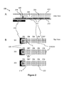
- Figures 1A and 1B illustrate first and second top views, respectively, of a droplet actuator 100 in use during a first and second phase, respectively, of a droplet splitting operation.
- Droplet actuator 100 makes use of an arrangement that is not suitably arranged for efficiently splitting a droplet using the specific technique shown without loss of magnetically responsive beads.
- Droplet actuator 100 includes a first substrate 110 and a second substrate (not shown) arranged with a gap therebetween, which serves as a fluid path.
- First substrate 110 includes a set of droplet operation electrodes 112 configured for conducting droplet operations on slug-shaped droplet 114, which is suspended in a filler fluid and includes magnetically responsive beads 116.
- a magnet 118 may be arranged in sufficient proximity to droplet operation electrodes 112 to permit some degree of immobilization of the magnetically responsive beads 116.
- Figures 1A and 1B show a splitting operation that is taking place in the presence of a magnetic field produced within droplet actuator 100 by magnet 118.
- the placement of magnet 118 is not suitable for localizing substantially all of magnetically responsive beads 116 in a centralized location (e.g., away from the edges of the droplet) within the portion of droplet 114 that is selected to retain the beads after the splitting operation. Consequently, a certain quantity of magnetically responsive beads 116 bridge splitting zone 120 during the droplet splitting operation, as shown in Figure 1A , and a loss of beads results, as shown in Figure 1B.
- Figure 1B shows a first droplet 122 that contains a certain quantity of the original quantity of magnetically responsive beads 116 and a second droplet 124 that contains a certain remaining quantity of the original quantity of magnetically responsive beads 116.
- the end result of the illustrated splitting operation is a loss of magnetically responsive beads 116.
- the inventors have discovered that a contributing factor to the loss of beads is that a full quantity of magnetically responsive beads 116 is not suitably attracted, immobilized, and retained at a centralized location within droplet 114 and/or at a sufficient distance from splitting zone 120.
- the invention provides improved droplet actuators that have various magnet configurations in which magnets are arranged for efficiently splitting bead-containing droplets and washing magnetically responsive beads are described with reference to Figures 2 , 3 , 4 , 5A, and 5B .
- Figures 2 , 3 , 4 , 5A, and 5B illustrate nonlimiting examples of magnet configurations in combination with a droplet actuator splitting droplets with little or no bead loss, and are, among other things, useful for efficiently washing magnetically responsive beads.
- One or more magnets may be arranged in proximity to a droplet on a droplet actuator such that magnetically responsive beads are suitably attracted and immobilized within the droplet, preferably at a centralized location away from the neck that forms during splitting operations.
- the spitting operation may be performed in a droplet slug which is at a distance from the immobilized beads which is sufficient to reduce or eliminate bead loss.
- one or more magnets may be arranged with respect to the droplet actuator structure above, below, and/or beside, the magnetically-responsive bead-containing droplet and any combinations thereof to achieve this purpose.
- Figures 2A and 2B illustrate side and top views of a droplet actuator 200.
- the magnet is placed at a position which is sufficiently distant from the portion of the droplet which is breaking during the splitting operation, splitting zone 224 (or vice versa, the splitting zone may be said to be placed at sufficient distance from the magnet position), to reduce or eliminate bead loss during a droplet splitting operation.
- the magnet is positioned so that the beads are generally centrally located along a lateral diameter L of the droplet (top view).
- Droplet actuator 200 includes a first substrate 210 and a second substrate 212 separated to provide a gap for conducting droplet operations, though only one substrate is required.
- Droplet actuator 200 may include a magnet 216 that is arranged in sufficient proximity to droplet 218/222 to substantially immobilize magnetically responsive beads 220 during a droplet splitting operation.
- the magnet may be arranged as a component of the droplet actuator and/or in sufficient proximity to the droplet actuator to immobilize the magnetically responsive beads in droplet 218/222 in the gap.
- Droplet 218/222 may be surrounded by a filler fluid (not shown). Droplet 218/222 contains a quantity of magnetically responsive beads 220 immobilized by magnet 216.
- Magnet 216 is positioned relative to one or more droplet operation electrodes 214, in order to localize beads 220 in a region of the portion of the droplet 218/222 that is to form droplet 218 without permitting substantial loss of beads 218 during the droplet splitting operation to droplet 222.
- a splitting operation is achieved without substantial loss of magnetic beads 220 by: as shown in 201, providing a droplet actuator 200 with electrodes activated (ON) to form combined droplet 218/222 and magnet 216 is arranged in a position which causes substantially all of magnetically responsive beads 220 to be attracted to magnet 216 in a zone of droplet 218/222 that prevents substantial loss of magnetically responsive beads 220 to droplet 222.
- Magnet 216 may be arranged so that magnetically responsive beads 220 attracted thereto are localized at a generally centralized location along lateral diameter L within combined droplet 218/222 and away from the droplet split zone 224.
- an intermediate electrode is deactivated (OFF) to cause splitting at split zone 224.
- Substantially all magnetically responsive beads 220 are retained in droplet 218, and droplet 222 is formed and is substantially free of magnetically responsive beads 220, as shown in 203.
- a process for washing magnetically responsive beads 220 may, in one embodiment, involve the repetition of droplet merging (with a wash droplet), bead immobilization, splitting, and bead resuspension operations until acceptable levels of washing are achieved.
- Figure 3 illustrates a side view of a droplet actuator 300.
- Droplet actuator 300 is generally configured as described in Figure 2 , except that it includes two magnets, magnet 310a and 310b, arranged below and above droplet 218.
- the magnets may be integral with droplet actuator 300 and/or arranged in close proximity to the outer side of first substrate 210 and second substrate 212.
- the magnets 310a and 310b may be arranged such that opposite poles are facing one another. In one example, the north or positive pole of magnet 310a is facing the south or negative pole of magnet 310b, as shown in Figure 3 .
- Magnets 310a and 310b may be separate magnets or, alternatively, magnets 310a and 310b may be opposite poles of a single U-shaped, C-shaped, or horseshoe-shaped permanent magnet or electromagnet.
- the arrangement of magnets 310a and 310b may cause magnetically responsive beads 220 to be immobilized and retained in a column-shaped cluster.
- the magnets are preferably arranged to localize beads within droplet 218 in a position which is away from splitting zone 224 in the portion of the combined droplet (not shown) in which the beads are to be retained. Further, the magnets are preferably aligned to centrally localize the beads along lateral diameter L within the combined droplet (not shown).
- Figures 4A and 4B illustrate side views of a droplet actuator 400.
- Droplet actuator 400 is generally configured like droplet actuator 200 described in Figure 2 , except that it includes four magnets arranged at positions surrounding the droplet.
- the arrangement illustrates the embodiment in which multiple magnet pairs with positive/negative poles facing each other are arranged to generally centrally locate beads 220 in the combined droplet prior to splitting.
- the beads are generally centrally located along a vertical dimension V and a lateral dimension L.
- droplet actuator 400 includes four magnets, such as a magnet 410a, 410b, 410c, and 410d.
- Magnets 410a and 410b may be arranged in close proximity to the droplet, equally spaced on either side of the droplet, with opposite poles facing each other.
- the north pole of magnet 410a may face the south pole of magnet 410b.
- Magnets 410c and 410d may be arranged in close proximity to the droplet, equally spaced on either side of the droplet, with opposite poles facing each other.
- the north pole of magnet 410d may face the south pole of magnet 410c.
- Magnet pair 410a/410b may generally be aligned at right angles around the droplet relative to magnet pair 410c/410d.
- magnet pair 410a/410b has a vertical orientation around the droplet
- magnet pair 410c/410d has a horizontal orientation around the droplet. Any orientation around the droplet achieving the generally central localization of beads along lateral dimension L and vertical dimension V will suffice to achieve the desired central immobilization.
- Magnets 410a and 410b may be arranged in close proximity to the outer side of first substrate 210 and second substrate 212, respectively, such that the magnetic field of magnets 410a and 410b may pass through the gap between first substrate 210 and second substrate 212 of droplet actuator 400. Magnets 410a and 410b are arranged such that opposite poles are facing one another. In one example, the north pole of magnet 410a is facing the south pole of magnet 410b, as shown in Figure 4 .
- magnets 410c and 410d are arranged in close proximity to a first side and a second side, respectively, of droplet actuator 400, such that the magnetic field of magnets 410c and 410d may pass through the gap of droplet actuator 400 and perpendicular to the magnetic field of magnets 410a and 410b.
- Magnets 410c and 410d are arranged such that opposite poles are facing one another. In one example, the north pole of magnet 410d is facing the south pole of magnet 410c, as shown in Figure 4 .
- Magnets 410a and 410b may be separate magnets or, alternatively, magnets 410a and 410b may be opposite poles of a single U-shaped, C-shaped, or horseshoe-shaped permanent magnet or electromagnet.
- magnets 410c and 410d may be separate magnets or, alternatively, magnets 410c and 410d may be opposite poles of a single U-shaped, C-shaped, or horseshoe-shaped permanent magnet or electromagnet.
- the magnetically responsive beads 220 are magnetically immobilized and retained in a cluster that is centralized within the combined droplet and retained in droplet 218 following the splitting operation.
- Figures 5A and 5B illustrate a first and second top view, respectively, of a droplet actuator 500 during a first and second phase, respectively, of a droplet splitting operation.
- Droplet actuator 500 may alternatively be configured like any of the example droplet actuators 200, 300, and 400.
- Droplet actuator 500 of Figures 5A and 5B makes use of magnet forces that are suitably arranged for use in a splitting operation designed to result in substantially complete retention of beads in a single droplet, such as a process for washing magnetically responsive beads.
- Figures 5A and 5B show a splitting operation that is taking place at a sufficient distance from localized beads 220 to permit a splitting operation that results in substantially complete retention of magnetically responsive beads in droplet 218 and a droplet that is substantially free of magnetically responsive beads.
- the position of magnet face 510 is suitably arranged to magnetically immobilize substantially all of magnetically responsive beads 220 at a centralized location within the droplet and at a distance from the splitting zone that is sufficient to achieve the desired retention of magnetically responsive beads 220 in droplet 218.
- substantially no quantity of magnetically responsive beads 220 bridges a splitting zone 512 during the droplet splitting operation, as shown in Figure 5A , and substantially no loss of beads occurs.
- Figure 5B shows droplet 218 that contains substantially all magnetically responsive beads 220.
- the end result of a splitting operation that takes place substantially outside of the magnet forces is that there is substantially no loss of magnetically responsive beads 220 because substantially all of magnetically responsive beads 220 are suitably attracted, immobilized, and retained at a centralized location within the fluid.
- Figure 6 illustrates a side view of a droplet actuator 600 that includes a magnetic shield for reducing the crossover of magnetic fields.
- Droplet actuator 600 includes a top plate 610 and a bottom plate 614 that are arranged having a gap 618 therebetween.
- An arrangement of electrodes 622 e.g., electrowetting electrodes, may be associated with bottom plate 614 for performing droplet operations and an electrode, such as reservoir electrode 626 that is associated with a fluid reservoir 630 that contains a quantity of fluid 634.
- One or more droplets may be dispensed from the quantity of fluid 634 of reservoir 630 for manipulation along electrodes 622.
- fluid 634 and any droplets dispensed therefrom may optionally contain beads (not shown), which may, in some cases, be magnetically responsive.
- Droplet actuator 600 further includes a magnet 638 that is arranged in proximity to the one or more electrodes 622.
- Magnet 638 may be arranged in sufficient proximity to electrodes 622 in order to permit immobilization of magnetically responsive beads (not shown), e.g., in a droplet positioned on an electrode.
- the purpose of magnet 638 is to magnetically immobilize and retain magnetically responsive beads during a droplet splitting operation, e.g., a splitting operation that may be performed in a process for washing magnetically responsive beads.
- droplet actuator 600 includes a magnetic shield 642 that is arranged in sufficient proximity to fluid reservoir 630 to shield the contents thereof from nearby magnetic fields, such as the magnetic field of magnet 638.
- Magnetic shield 642 may, for example, be formed of Mu-metal that has sufficiently high magnetic permeability and that is suitable to reduce, preferably substantially eliminate, unwanted magnetic fields from the magnet within fluid reservoir 630.
- magnetic shield 642 may be formed of Mu-metal that is supplied by McMaster-Carr (Elmhurst, IL).
- Other examples of magnetic shield 642 materials include Permalloy, iron, steel and nickel.
- Droplet actuator 600 is not limited to one magnetic shield and one magnet only, any number of magnetic shields and magnets may be installed therein. Therefore, by use of one or more magnetic shields, the exposure of magnetic beads (not shown) within droplets to magnetic fields may be limited to desired regions only of droplet actuator 600. Magnetic shields may be included on any surface of the droplet actuator and in any arrangement which facilitates suitable shielding.
- a droplet actuator may be employed to perform multiple assays in parallel and, consequently, there may be a need for generally simultaneous washing of the various magnetic beads that may be manipulated within multiple lanes of electrodes.
- a wash operation or assay that is performed at a certain location using an associated magnet may be affected by the magnetic field of a distant magnet (i.e., crossover of magnetic fields).
- crossover of magnetic fields between any two magnets may be reduced, preferably substantially eliminated, via the strategic placement of one or more magnetic shields, such as magnetic shield 642, within the droplet actuator.
- Figure 7 illustrates a top view of a droplet actuator 700 that includes a magnet whose poles are oppositely arranged for reducing the crossover of magnetic fields.
- Droplet actuator 700 includes an arrangement of electrodes 710, e.g., electrowetting electrodes, for performing droplet operations on one or more droplets (not shown). Additionally, a magnet 714 is arranged in close proximity to a first lane of electrodes 710, a magnet 718 is arranged in close proximity to a second lane of electrodes 710, a magnet 722 is arranged in close proximity to a third lane of electrodes 710, and a magnet 726 is arranged in close proximity to a fourth lane of electrodes 710. Magnets 714, 718, 722, and 726 may be arranged in sufficient proximity to electrodes 710 in order to permit immobilization of magnetically responsive beads (not shown) within one or more droplets (not shown) located on one or more of the electrodes.
- electrodes 710 e.g., electrowetting electrodes
- the poles of adjacent magnets are oppositely arranged, which causes the adjacent magnetic fields to cancel.
- the north pole of magnet 722 is oriented upward
- the south pole of magnet 726 is oriented upward. In this way, the magnetic fields are cancelled and the crossover of magnetic fields between magnets 714, 718, 722, and 726 may be reduced, preferably substantially eliminated.
- Figure 8 illustrates a map 800 of magnetic fields arranged in a relationship such as the one shown in Figure 7 .
- the invention also provides techniques for reducing carryover in a droplet actuator, as well as techniques for improving detection operations.
- Figure 9 illustrates a top view of a droplet actuator 900 by which an operation to reduce carryover at a droplet detection region may be performed.
- Droplet actuator 900 includes an arrangement of electrodes 910, e.g., electrowetting electrodes, for subjecting droplets to droplet operations. Additionally, droplet actuator 900 includes a designated detection region 914 at, for example, a certain electrode 910. Detection region 914 is used to detect droplets positioned thereon or passing therethrough during droplet operations. In one example, droplet detection is performed using a photomultiplier tube (PMT) or photon-counting PMT that is associated with detection region 914.
- PMT photomultiplier tube
- a PMT (not shown) is used to measure light (i.e., detect photons) emitted from a droplet (e.g., due to fluorescence and/or chemiluminescence) when at the electrode that is associated with detection region 914.
- a build up of substances at a detection region may occur due to carryover, which involves beads or other substances being left behind on surfaces and/or in filler fluid during droplet operations. Carryover may interfere with accurate detection of signals from subsequent droplets and/or interfere with droplet operations by affected electrodes.
- a droplet sequencing operation of the invention reduces, preferably substantially eliminates, carryover at detection region 914 by providing a series of alternating assay droplets 918 and wash droplets 922.
- an assay droplet 918a passes through detection region 914, followed by a wash droplet 922a, followed by an assay droplet 918b, followed by a wash droplet 922b, followed by an assay droplet 918c, followed by a wash droplet 922c, followed by an assay droplet 918d, which is followed by a wash droplet 922d.
- wash droplets 922a, 922b, 922c, and 922d perform a cleaning operation of the surfaces that are associated with detection region 914.
- the cleaning process of the invention is not limited to the sequence that is shown in Figure 9 . Any sequence is possible as long as the sequence includes a suitable number of wash droplets in order to suitably clean the detection region.
- the larger droplet may be subjected to droplet operations as a slug (e.g., a slug occupying 4 electrodes) or as a single large droplet (e.g., a 4X droplet occupying as many electrodes as it naturally covers without being formed into a slug).
- a slug e.g., a slug occupying 4 electrodes
- a single large droplet e.g., a 4X droplet occupying as many electrodes as it naturally covers without being formed into a slug.
- Each arrangement may result in a different cleaning result. It is also not necessary for the assay droplets and wash droplets to follow the same path. For example, their paths may intersect at the location needing to be cleaned.
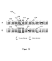
- FIGs 10A and 10B illustrate a top view of a droplet actuator 1000 by which another operation for reducing carryover may be performed.
- Droplet actuator 1000 includes an arrangement of electrodes 1010, e.g., electrowetting electrodes, for performing droplet operations on one or more droplets, such as assay droplets 1014 and 1018 ( Figure 10A ) and wash droplet 1022 ( Figure 10B ).
- electrodes 1010 e.g., electrowetting electrodes
- a magnet 1026 is arranged in close proximity to a certain electrode 1010.
- Magnet 1026 may be arranged in sufficient proximity to the certain electrode 1010 in order to permit immobilization of magnetically responsive beads within one or more droplets, such as magnetic beads 1030 within assay droplet 1014.
- a quantity of "satellite" droplets may be left behind at the point at which the split occurs.
- a droplet split operation by which assay droplet 1014 is formed by splitting from assay droplet 1018 may result in a certain quantity of satellite droplets 1034 being left behind upon a certain electrode 1010.
- Satellite droplets, such as satellite droplets 1034 may be the source of carryover (cross contamination) from one droplet to another, which is not desired.
- Figure 10B illustrates that a wash droplet, such as wash droplet 1022, may be transported along electrodes 1010 subsequent to the assay operations of, for example, assay droplets 1018 and 1014 in order to capture satellite droplets 1034 and transport them away prior the next assay operation occurs.
- electrodes 1010 are cleaned between assay operations.
- the cleaning process of the invention is not limited to the sequence that is shown in Figures 10A and 10B . Any sequence is possible as long the sequence includes a suitable number of wash droplets in order to suitably clean the electrodes.
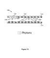
- FIGS 11A, 11B, and 11C illustrate side views of droplet actuator 1100 by which respective operations for improving the sensitivity of droplet detection may be performed.
- Droplet actuator 1100 includes a top plate 1110 and a bottom plate 1114 that are arranged having a gap 1118 therebetween.
- An arrangement of electrodes 1122 e.g., electrowetting electrodes, may be associated with bottom plate 1114 for performing droplet operations on a droplet 1126.
- a PMT window 1130 may be associated with top plate 1110, by which a PMT (not shown) is used to measure light (i.e., detect photons 1134) emitted from droplet 1126.
- Figure 11A shows a method of improving the sensitivity of droplet detection by spreading out a droplet, such as droplet 1126, in order to increase the surface area that is exposed to PMT window 1130 and, thus, increase the number of photons 1134 that may be detected.
- a droplet may be spread linearly across one or more electrodes 1122 depending on the volume of the droplet.
- a buffer droplet may be added to make the droplet larger, as long as losses due to dilution by the buffer droplet are offset by the increased droplet area exposed to the PMT.
- Figure 11B shows droplet 1126 that is spread continuously across multiple electrodes 1122, which increases the number of photons 1134 that may reach PMT window 1130 and may be detected by the PMT.
- Figure 11C shows a scenario wherein droplet 1126 is split up into multiple droplets 1126, such as droplets 1126a, 1126b, 1126c, and 1126d that are on multiple electrodes 1122.
- the surface area that is exposed to PMT window 1130 is increased, which increases the number of photons 1134 that may reach PMT window 1130 and may be detected by the PMT.
- the spreading of a droplet, such as droplet 1126 is not limited to linear spreading only.
- the droplet may be spread two dimensions, such as across a grid or array or electrodes 1122, in order to increase the surface area that is exposed to PMT window 1130.
- one or more large-area electrodes may be provided, across which one or more droplets may be spread.
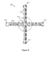
- Figure 12 illustrates a top view of a droplet actuator 1200 for improving the sensitivity of droplet detection.
- Droplet actuator 1200 includes an arrangement of electrodes 1210, e.g., electrowetting electrodes, for performing droplet operations on multiple droplets 1214. Additionally, droplet actuator 1200 may include a droplet detection region 1218 that has an associated PMT (not shown) for measuring light that is emitted from a certain droplet 1214 when present. In order to reduce, preferably substantially eliminate, the carryover of light from a distant droplet 1214 to droplet detection region 1218, a minimum distance d is maintained in all directions between the outer perimeter of droplet detection region 1218 and any distant droplets 1214 within droplet actuator 1200, as shown in Figure 12 .
- the minimum distance d is sufficiently large to reduce, preferably substantially eliminate, the carryover of light from a distant droplet 1214 to droplet detection region 1218.
- a spacing is maintained during detection between the target droplet 1214 that is being measured and a distant droplet 1214, such that the carryover of light from the distant droplet 1214 to droplet detection region 1218 is reduced, preferably substantially eliminated.
- the distance d is an integer multiple m of a unit electrode size, and the droplet detection may be conducted on a set of electrodes which are electrically connected as an m phased bus.
- Figure 13 (described below) describes a scenario wherein the real-estate with a droplet actuator is limited and, therefore, sufficient spacing between droplets, as described in Figure 12 , may not be achieved.
- cross-over from nearby droplets is eliminated by using optical elements, such as one or more lenses, which focus only light from the droplet being interrogated onto the sensor and eliminates signal from other droplets.
- optical elements such as one or more lenses
- Figure 13 illustrates a side view of a droplet actuator 1300 for improving the sensitivity of droplet detection.
- Droplet actuator 1300 includes a top plate 1310 and a bottom plate 1314 that are arranged having a gap 1318 therebetween.
- An arrangement of electrodes 1322 e.g., electrowetting electrodes, may be associated with bottom plate 1314 for performing droplet operations on droplets, such as a droplet 1326 and a droplet 1330.
- a PMT window 1334 may be associated with top plate 1310, by which a PMT (not shown) is used to measure light (i.e., detect photons 1338) that is emitted from, for example, droplet 1326.
- a mask 1342 is provided upon top plate 1310. The purpose of mask 1342 is to block light from a distant droplet from carrying over to PMT window 1334, which is the detection region of a target droplet.
- Mask 1342 may be formed upon top plate 1310 via a layer of any light-absorbing material, as long as the material that is used is compatible with the electrowetting process and does not unduly interfere with the droplet actuator operations.
- mask 1342 may be formed by applying a layer of black paint to top plate 1310, such that one or more windows, such as PMT window 1334, are provided in selected detection regions of droplet actuator 1300.
- mask 1342 reduces, preferably substantially eliminates, the carry over of light from distant droplet 1330 to the target droplet 1326 at PMT window 1334.
- the mask 1342 is formed by an opaque conductor on the side of the top plate 1310 facing the droplet.
- the conductor may, for example, be aluminum, chromium, copper, or platinum.
- the conductor may additionally serve as an electrical reference electrode.
- Figures 14A and 14B illustrate top views of a modular droplet actuator assembly 1400, which is a nonlimiting example of a universal assembly for orienting a magnet assembly to a droplet actuator.
- Modular droplet actuator assembly 1400 may include, for example, a mount 1410, a magnet assembly 1420, and a droplet actuator 1430.
- Figure 14A shows modular droplet actuator assembly 1400 when disassembled.
- Figure 14B shows modular droplet actuator assembly 1400 when assembled.
- Magnet assembly 1420 may include a substrate 1424 upon which is mounted one or more magnets 1428, as shown in Figure 14A .
- the magnets 1428 may be permanently affixed to substrate 1424 or may be removable.
- Removable magnets 1428 facilitate selection by a user of magnets having desired properties, such as desired magnet strength.
- a droplet actuator instrument is provided with a droplet actuator assembly 1400 including a mount 1410 and a magnet assembly 1420 without magnets.
- the user is also provided with magnets having specified properties which may be affixed by the user to the magnet assembly 1420.
- the user is also provided with sets of magnets having various specified characteristics such that the user may select a set of one or more magnets having desired properties and affix the selected set to the magnet assembly 1420.
- Magnets may be marked or coded (e.g., color coded) to facilitate selection of magnets having appropriate properties, as well as marked to show the orientation of the magnet's magnetic field (e.g., by color coding or otherwise marking the North and South faces of the magnets).
- the magnet assembly 1420 may be marked to show the desired orientation of magnets inserted therein, and in some embodiments, magnets may be shaped to permit them to be affixed to the magnet assembly 1420 only in an appropriate orientation.
- the user may be provided with magnet assemblies 1420 having magnets already affixed thereto, wherein the magnet assemblies 1420 each have different magnet configurations, e.g., sets of magnets having different properties.
- the user may select the magnet configuration having magnets having properties appropriate to the user's desired use for the instrument.
- Magnet assembly 1420 may be marked or otherwise color coded to facilitate selection by the user. Magnet properties may, for example, be selected based on the properties of beads selected by the user.
- Droplet actuator 1430 may include a substrate 1434 upon which is an arrangement of electrodes 1438, e.g., electrowetting electrodes, as shown in Figure 14A .
- a second (top) substrate may also be included (not shown).
- Magnet assembly 1420 is designed such that magnets 1428 substantially align with certain electrodes 1438 of interest on droplet actuator 1430.
- parallel configurations of magnets may be present for conducting parallel assay steps on droplet actuator 1430.
- Magnets may be configured and oriented, for example, according to the various configurations and orientations described herein.
- Mount 1410 may serve as a universal platform for mounting a magnet assembly, such as magnet assembly 1420, and a droplet actuator, such as droplet actuator 1430.
- mount 1410 is configured to accept a wide variety of magnet assemblies 1420 and a wide variety of droplet actuators 1430.
- Magnet assembly 1420 may include one or more magnets arranged in any of a variety of patterns and employing any of a variety of magnet properties.
- Figure 14 illustrates a row of magnets, but magnets may also be provided in a grid or any arrangement that places the magnets in their proper position in relation to the droplet actuator 1430 in order to facilitate desired operations on the droplet actuator.
- magnet assembly 1420 and droplet actuator 1430 may be installed into mount 1410 via respective fittings 1418 and 1414.
- Fittings may, for example, involve slots into which the mount 1410 may be fitted, openings on the mount 1410 for accepting posts on the magnet assemblies 1420 or vice versa, openings on the mount 1410 for accepting screws on the magnet assemblies 1420, threaded posts for accepting bolts, various spring loaded mechanisms, recessed trays, complimentary fittings, and the like. Any mechanism which facilitates sufficiently secure attachment to permit the device to function for its intended purpose will suffice.
- mount 1410 may include multiple fittings for multiple possible positions of magnet assembly 1420 and/or droplet actuator 1430, and/or mounting of multiple magnet assemblies 1420 and/or multiple droplet actuators 1430 in a single mount 1410. Further, mount 1410 may be configured to permit magnet assemblies 1420 to be mounted above, below and/or beside the droplet actuator 1430, i.e., in any relationship with the droplet actuator. With droplet actuator 1430 installed in modular mount 1410, any magnet assembly of interest, such as magnet assembly 1420, may be inserted into modular droplet actuator assembly 1400 via, for example, the slot.
- Figure 15 illustrates a side view of a modular droplet actuator assembly 1500, which is another nonlimiting example of a universal assembly for orienting a magnet assembly to a droplet actuator, similar to the assembly 1400 shown in Figure 14 , except that mount 1410 is replaced with a mount 1510.
- Mount 1510 includes recessed trays into which magnet assembly 1420 and droplet actuator 1430 may be fitted in order to provide a "drop in" method of loading.
- an aspect of the invention is that the slots or other attachment means serve to orient the magnet substrate and the droplet actuator so as to align the magnets on the magnet assembly with the appropriate electrodes or electrode paths on the droplet actuator. In this manner, the magnets may be removed when not needed for an assay. Additionally, different magnet mounts with different distributions of magnets may be provided for different types of assays or different droplet actuator layouts.
- magnets selected for use with the invention may be permanent or electromagnets. There may be a relationship between the magnetically responsive content of the beads in the droplet and the magnetic strength/pull force. Therefore, the magnetic strength/pull force of the magnet may be selected relative to the responsiveness of the magnetic beads such that it is:
- the magnet may have high magnetic strength (in Tesla) with lesser pull force (in pounds).
- magnet is a neodymium permanent magnet that has a surface field strength of about 1 Tesla (T).
- the magnet is an electromagnet that has a surface field strength of about 1 T, which may be turned on and off electronically. Where a permanent magnet is used, the magnet may be moved away from the magnetically responsive bead-containing droplet for uses in which it is desirable to remove the influence of the magnetic field.
- ranges of magnetic strength that generally encompasses the useful strength of the present invention can include: a broad range of 0.01 T to 100 T (pulsed) or 45 T (continuous); an intermediate range of 0.01 T to 10 T; and a narrow range of 0.1 T to 1 T (preferably 0.5 T).
- Droplets including magnetic beads and subjected to droplet splitting operations may include any of a wide variety of samples, reagents, and buffers useful for conducting assays using the beads.
- the droplet may include a buffer, such as a phosphate-buffered saline (PBS) buffer with a surfactant that is suitable for use in magnetic based immunoassays.
- PBS phosphate-buffered saline
- PBS phosphate-buffered saline
- surfactants are those which facilitate immobilization and/or resuspension of beads following immobilization by magnetic forces.
- the surfactant and amount of surfactant may be adjusted to provide a substantial improvement in resuspension as compared to a control solution lacking the surfactant.
- the droplet includes PBS buffer with about 0.01% Tween ® 20.
- a hydrophilic polymer and/or surfactant may be included in the droplet to facilitate retention and resuspension of magnetically responsive beads during splitting operation.
- the droplet may include a wide variety of liquids immiscible with the filler fluid.
- buffers include, but are not limited to, phosphate-buffered saline (PBS) buffer and Tris buffer saline.
- the droplet fluid includes a buffer, such as the PBS buffer, and any surfactant that is suitable for use in magnetic based immunoassays.
- Preferred hydrophilic polymers and surfactants are those which facilitate resuspension of beads following immobilization by magnetic forces.
- the surfactant and amount of surfactant may be adjusted to provide a substantial improvement in resuspension as compared to a control solution lacking the surfactant.
- Examples of surfactants that are suitable for use in magnetic based immunoassays include, but are not limited to, polysorbate 20, which is commercially known as Tween ® 20, and Triton X-100.
- Tween ® 20 may be supplied by, for example, Pierce Biotechnology, Inc. (Woburn, MA).
- Triton ® X-100 may be supplied by, for example, Rohm & Haas Co (Philadelphia, PA).
- the droplet fluid within the droplet actuator is a mix of PBS with Tween ® 20 in the range of from about 0.001% to about 0.1%. In another example, the droplet fluid within the droplet actuator is a mix of PBS with about 0.01 % Tween ® 20.
- pluronic surfactants polyethylene glycol (PEG), methoxypolyethylene glycol (MPEG), poly-sorbate (polyoxyethylene sorbitan monooleates or Tween@), polyoxyethylene octyl phenyl ether (Triton X-100®), polyvinyl pyrollidone, polyacrylic acid (and crosslinked polyacrylic acid such as carbomer), polyglycosides (nonionic glycosidic surfactants such as octyl glucopyranoside) and soluble polysaccharides (and derivatives thereof) such as heparin, dextrans, methyl cellulose, propyl methyl cellulose (and other cellulose esters and ethers), dextrins, maltodextrins, galactomannans, arabinogalactans, beta glucans, alginates, agar, carrageenan, and plant gums such as xanthan gum, psyllium, guar gum
- Patents 6,773,566 entitled, “Electrostatic Actuators for Microfluidics and Methods for Using Same,” issued on August 10, 2004 and 6,565,727 , entitled, “Actuators for Microfluidics Without Moving Parts,” issued on January 24, 2000, both to Shenderov et al.; and International Patent Application No. PCT/US 06/47486 to Pollack et al. , entitled, “Droplet-Based Biochemistry,” filed on December 11, 2006, the disclosures of which are incorporated herein by reference. Droplet actuator techniques for immobilizing magnetic beads and/or non-magnetic beads are described in the foregoing international patent applications and in Sista, et al., U.S. Patent Application Nos.
- the droplet is a sample fluid, such as a biological sample, such as whole blood, lymphatic fluid, serum, plasma, sweat, tear, saliva, sputum, cerebrospinal fluid, amniotic fluid, seminal fluid, vaginal excretion, serous fluid, synovial fluid, pericardial fluid, peritoneal fluid, pleural fluid, transudates, exudates, cystic fluid, bile, urine, gastric fluid, intestinal fluid, fecal samples, fluidized tissues, fluidized organisms, biological swabs and biological washes.
- a biological sample such as whole blood, lymphatic fluid, serum, plasma, sweat, tear, saliva, sputum, cerebrospinal fluid, amniotic fluid, seminal fluid, vaginal excretion, serous fluid, synovial fluid, pericardial fluid, peritoneal fluid, pleural fluid, transudates, exudates, cystic fluid, bile, urine, gastric fluid, intestinal fluid, f
- the fluid that is loaded includes a reagent, such as water, deionized water, saline solutions, acidic solutions, basic solutions, detergent solutions and/or buffers.
- a reagent such as water, deionized water, saline solutions, acidic solutions, basic solutions, detergent solutions and/or buffers.
- the fluid that is loaded includes a reagent, such as a reagent for a biochemical protocol, such as a nucleic acid amplification protocol, an affinity-based assay protocol, a sequencing protocol, and/or a protocol for analyses of biological fluids.
- the gap is typically filled with a filler fluid.
- the filler fluid may, for example, be a low-viscosity oil, such as silicone oil.
- Other examples of filler fluids are provided in
- droplets with beads can be combined using droplet operations with one or more wash droplets. Then, while retaining the beads (e.g., physically or magnetically) using magnet configurations of the invention, the merged droplet may be divided using droplet operations into two or more droplets: one or more droplets with beads and one or more droplets without a substantial amount of beads. In one embodiment, the merged droplet is divided using droplet operations into one droplet with beads and one droplet without a substantial amount of beads.
- each execution of a washing protocol results in retention of sufficient beads for conducting the intended assay without unduly detrimental effects on the results of the assay.
- each division of the merged droplet results in retention of more than 90, 95, 97, 98, 99, 99.1, 99.2, 99.3, 99.4, 99.5, 99.6, 99.7, 99.8, 99, 99.9. 99.99, 99.999, 99.9999, 99.99999, or 99.999999 percent of beads.
- each execution of a washing protocol to achieve a predetermined reduction in the concentration and/or amount of removed substance results in retention of more than 99, 99.1, 99.2, 99.3, 99.4, 99.5, 99.6, 99.7, 99.8, 99, 99.9. 99.99, 99.999, 99.9999, 99.99999, or 99.999999 percent of beads.
- the amount of retained beads is calculated and the results are adjusted accordingly.
- beads can be washed in reservoirs in which the bead-containing droplet and wash droplets are combined, beads are retained (for example by a magnet, by physical structures, electrostatic forces), and droplets lacking beads are dispensed from the reservoir using droplet operations.
- beads can be washed by dilute-and-dispense strategy whereby a wash buffer is added to the reservoir to dilute the contents, magnetically responsive beads are localized within the reservoir with a magnet and most of the solution is dispensed from the reservoir, and this cycle is repeated till acceptable levels of washing are achieved.
- washing magnetically responsive beads may generally include the following steps:
- Step (5) is not required in each washing cycle; however, it may be useful to enhance washing by freeing contaminants which may be trapped in the immobilized beads. Steps may be performed in a different order, e.g., steps (2) and (3) may be reversed. Steps in the washing protocol may be accomplished on a droplet actuator using droplet operations as described herein.
- a hydrophilic polymer and/or surfactant is included to prevent or reduce bead aggregation. Hydrophilic polymers and surfactants should be selected and used in amounts which reduce or eliminate bead aggregation and minimize non-specific adsorption while at the same time not resulting in significant loss of target analytes or reagents from the droplet.
- the hydrophilic polymer and/or surfactant reduces bead clumping in a droplet in a non-gaseous filler fluid and specifically does not serve to reduce molecular adsorption of droplet components to a surface of the droplet actuator.
- the number of magnetically responsive beads can range from 1 to several 100,000's.
- the invention makes use of one to 100 magnetically responsive beads per droplet.
- the invention may make use of 1, 2, 3, 4, 5, 6, 7, 8, 9, 10 ... 100 magnetically responsive beads per droplet.
- the number of magnetically responsive beads is from one to 10. Use of smaller numbers of magnetically responsive beads permits larger beads to be used.
- the invention makes use of one to 100 magnetically responsive beads per droplet, where the beads have an average diameter of about 25 to about 100 microns.
- the invention makes use of one to 10 magnetically responsive beads per droplet, where the beads have an average diameter of about 50 to about 100 microns.
Abstract
Description
- This invention was made with government support under
CA114993-01A2 - This application claims priority to and incorporates by reference related provisional
U.S. Patent Application Nos. 60/900,653, filed on February 9, 2007 60/980,772, filed on October 17, 2007 60/969,736, filed on September 4, 2007 60/980,762, filed on October 17, 2007 - The invention relates generally to the field of droplet actuators, and in particular, to droplet actuators configured for conducting droplet based protocols requiring droplet operations to be conducted using droplets comprising beads, especially magnetically responsive beads. The invention also relates to methods of making and using such droplet actuators.
- Droplet actuators are used to conduct a wide variety of droplet operations. A droplet actuator typically includes a substrate associated with electrodes for conducting droplet operations on a droplet operations surface thereof and may also include a second substrate arranged in a generally parallel fashion in relation to the droplet operations surface to form a gap in which droplet operations are effected. The gap is typically filled with a filler fluid that is immiscible with the fluid that is to be subjected to droplet operations on the droplet actuator.
- In some applications of a droplet actuator there is a need for using "beads" for various assays. For protocols that make use of beads, the beads are typically used to bind to one or more target substances in a mixture of substances. The target substances may, for example, be analytes or contaminants. There is a need for an efficient approach to bead washing on a droplet actuator in order to reduce the amount of one or more substances in a bead-containing droplet that may be in contact with or exposed to the surface of the bead or beads.
- One aspect of the invention provides efficient immobilization of magnetically responsive beads for droplet operations that make use of magnetically responsive beads in droplet-based applications. Examples include assays that require execution of bead washing protocols, such as pyrosequencing and immunoassay applications. In one example, the invention provides techniques employing magnetic forces for immobilizing magnetically responsive beads during droplet splitting operations. The techniques of the invention are particularly useful in protocols for washing magnetically responsive beads within a droplet actuator. Among other advantages, the techniques of the invention avoid undue clumping or aggregation of the magnetically responsive beads. During droplet splitting operations, the techniques can usefully immobilize substantially all of the magnetically responsive beads within a droplet. Techniques of the invention may ensure immobilization and retention of substantially all magnetically responsive beads during a droplet washing operation. Upon completion of a washing process, the techniques of the invention ensure resuspension of substantially all of the magnetically responsive beads within the liquid and with substantially no clumping or aggregation thereof.
- Another aspect of the invention provides improved droplet actuators and related methods for effecting improved droplet-based assay operations. Embodiments of the invention provide mechanisms for reducing the crossover of magnetic fields within a droplet actuator. Other embodiments of the invention provide mechanisms for reducing the carryover of beads and other substances within a droplet actuator. Yet other embodiments of the invention provide mechanisms for improving droplet detection operations within a droplet actuator.
- As used herein, the following terms have the meanings indicated.
- "Activate" with reference to one or more electrodes means effecting a change in the electrical state of the one or more electrodes which results in a droplet operation.
- "Bead," with respect to beads on a droplet actuator, means any bead or particle that is capable of interacting with a droplet on or in proximity with a droplet actuator. Beads may be any of a wide variety of shapes, such as spherical, generally spherical, egg shaped, disc shaped, cubical and other three dimensional shapes. The bead may, for example, be capable of being transported in a droplet on a droplet actuator or otherwise configured with respect to a droplet actuator in a manner which permits a droplet on the droplet actuator to be brought into contact with the bead, on the droplet actuator and/or off the droplet actuator. Beads may be manufactured using a wide variety of materials, including for example, resins, and polymers. The beads may be any suitable size, including for example, microbeads, microparticles, nanobeads and nanoparticles. In some cases, beads are magnetically responsive; in other cases beads are not significantly magnetically responsive. For magnetically responsive beads, the magnetically responsive material may constitute substantially all of a bead or one component only of a bead. The remainder of the bead may include, among other things, polymeric material, coatings, and moieties which permit attachment of an assay reagent. Examples of suitable magnetically responsive beads are described in
U.S. Patent Publication No. 2005-0260686 , entitled, "Multiplex flow assays preferably with magnetic particles as solid phase," published on November 24, 2005, the entire disclosure of which is incorporated herein by reference for its teaching concerning magnetically responsive materials and beads. The beads may include one or more populations of biological cells adhered thereto. In some cases, the biological cells are a substantially pure population. In other cases, the biological cells include different cell populations, e.g., cell populations which interact with one another. - "Droplet" means a volume of liquid on a droplet actuator that is at least partially bounded by filler fluid. For example, a droplet may be completely surrounded by filler fluid or may be bounded by filler fluid and one or more surfaces of the droplet actuator. Droplets may take a wide variety of shapes; nonlimiting examples include generally disc shaped, slug shaped, truncated sphere, ellipsoid, spherical, partially compressed sphere, hemispherical, ovoid, cylindrical, and various shapes formed during droplet operations, such as merging or splitting or formed as a result of contact of such shapes with one or more surfaces of a droplet actuator.
- "Droplet operation" means any manipulation of a droplet on a droplet actuator. A droplet operation may, for example, include: loading a droplet into the droplet actuator; dispensing one or more droplets from a source droplet; splitting, separating or dividing a droplet into two or more droplets; transporting a droplet from one location to another in any direction; merging or combining two or more droplets into a single droplet; diluting a droplet; mixing a droplet; agitating a droplet; deforming a droplet; retaining a droplet in position; incubating a droplet; heating a droplet; vaporizing a droplet; cooling a droplet; disposing of a droplet; transporting a droplet out of a droplet actuator; other droplet operations described herein; and/or any combination of the foregoing. The terms "merge," "merging," "combine," "combining" and the like are used to describe the creation of one droplet from two or more droplets. It should be understood that when such a term is used in reference to two or more droplets, any combination of droplet operations sufficient to result in the combination of the two or more droplets into one droplet may be used. For example, "merging droplet A with droplet B," can be achieved by transporting droplet A into contact with a stationary droplet B, transporting droplet B into contact with a stationary droplet A, or transporting droplets A and B into contact with each other. The terms "splitting," "separating" and "dividing" are not intended to imply any particular outcome with respect to size of the resulting droplets (i.e., the size of the resulting droplets can be the same or different) or number of resulting droplets (the number of resulting droplets may be 2, 3, 4, 5 or more). The term "mixing" refers to droplet operations which result in more homogenous distribution of one or more components within a droplet. Examples of "loading" droplet operations include microdialysis loading, pressure assisted loading, robotic loading, passive loading, and pipette loading.
- "Immobilize" with respect to magnetically responsive beads, means that the beads are substantially restrained in position in a droplet or in filler fluid on a droplet actuator. For example, in one embodiment, immobilized beads are sufficiently restrained in position to permit execution of a splitting operation on a droplet, yielding one droplet with substantially all of the beads and one droplet substantially lacking in the beads.
- "Magnetically responsive" means responsive to a magnetic field. "Magnetically responsive beads" include or are composed of magnetically responsive materials. Examples of magnetically responsive materials include paramagnetic materials, ferromagnetic materials, ferrimagnetic materials, and metamagnetic materials. Examples of suitable paramagnetic materials include iron, nickel, and cobalt, as well as metal oxides, such as Fe3O4, BaFe12O19, CoO, NiO, Mn2O3, Cr2O3, and CoMnP. "Washing" with respect to washing a magnetically responsive bead means reducing the amount and/or concentration of one or more substances in contact with the magnetically responsive bead or exposed to the magnetically responsive bead from a droplet in contact with the magnetically responsive bead. The reduction in the amount and/or concentration of the substance may be partial, substantially complete, or even complete. The substance may be any of a wide variety of substances; examples include target substances for further analysis, and unwanted substances, such as components of a sample, contaminants, and/or excess reagent. In some embodiments, a washing operation begins with a starting droplet in contact with a magnetically responsive bead, where the droplet includes an initial amount and initial concentration of a substance. The washing operation may proceed using a variety of droplet operations. The washing operation may yield a droplet including the magnetically responsive bead, where the droplet has a total amount and/or concentration of the substance which is less than the initial amount and/or concentration of the substance. Other embodiments are described elsewhere herein, and still others will be immediately apparent in view of the present disclosure.
- The terms "top" and "bottom" are used throughout the description with reference to the top and bottom substrates of the droplet actuator for convenience only, since the droplet actuator is functional regardless of its position in space.
- When a given component, such as a layer, region or substrate, is referred to herein as being disposed or formed "on" another component, that given component can be directly on the other component or, alternatively, intervening components (for example, one or more coatings, layers, interlayers, electrodes or contacts) can also be present. It will be further understood that the terms "disposed on" and "formed on" are used interchangeably to describe how a given component is positioned or situated in relation to another component. Hence, the terms "disposed on" and "formed on" are not intended to introduce any limitations relating to particular methods of material transport, deposition, or fabrication.
- When a liquid in any form (e.g., a droplet or a continuous body, whether moving or stationary) is described as being "on", "at", or "over" an electrode, array, matrix or surface, such liquid could be either in direct contact with the electrode/array/matrix/surface, or could be in contact with one or more layers or films that are interposed between the liquid and the electrode/array/matrix/surface.
- When a droplet is described as being "on" or "loaded on" a droplet actuator, it should be understood that the droplet is arranged on the droplet actuator in a manner which facilitates using the droplet actuator to conduct one or more droplet operations on the droplet, the droplet is arranged on the droplet actuator in a manner which facilitates sensing of a property of or a signal from the droplet, and/or the droplet has been subjected to a droplet operation on the droplet actuator.
-
-
Figures 1A and 1B illustrate first and second top views, respectively, of a portion of a droplet actuator in use during a first and second phase, respectively, of a droplet splitting operation; -
Figures 2A and 2B illustrate a side and top views of a section of a droplet actuator that includes a magnet that is placed at a position which is away from the splitting zone; -
Figure 3 illustrates a side view of a section of a droplet actuator that includes two magnets that are arranged above and below droplet; -
Figures 4A and 4B illustrate side views of a section of a droplet actuator that includes four magnets that are arranged at positions surrounding the droplet; -
Figures 5A and 5B illustrate a first and second top view, respectively, of a section of a droplet actuator during a first and second phase, respectively, of a droplet splitting operation; -
Figure 6 illustrates a side view of a section of a droplet actuator that includes a magnetic shield for reducing the crossover of magnetic fields; -
Figure 7 illustrates a top view of a section of a droplet actuator that includes a magnet having poles that are oppositely arranged for reducing the crossover of magnetic fields; -
Figure 8 illustrates a map of magnetic fields that are arranged in a relationship such as the one shown inFigure 7 ; -
Figure 9 illustrates a top view of a section of a droplet actuator arranged to reduce carryover at a droplet detection region; -
Figures 10A and 10B illustrate a top view of a section of a droplet actuator configured to reduce carryover; -
Figures 11A, 11B, and 11C illustrate side views of section of a droplet actuator configured for improving the sensitivity of droplet detection; -
Figure 12 illustrates a top view of a section of a droplet actuator configured for improving the sensitivity of droplet detection; -
Figure 13 illustrates a side view of a section of a droplet actuator configured for improving the sensitivity of droplet detection; -
Figures 14A and 14B illustrate top views of a modular droplet actuator assembly, which provides a universal assembly for orienting a magnet assembly to a droplet actuator; and -
Figure 15 illustrates a side view of a modular droplet actuator assembly, which is another nonlimiting example of a universal assembly for orienting a magnet assembly to a droplet actuator. - The present invention relates, among other things, to droplet actuators configured for immobilizing magnetically-responsive beads and to methods of making and using such droplet actuators. As an example, the droplet actuators are useful for immobilizing beads in droplets on the droplet actuators, thereby facilitating the execution of protocols which require immobilization of such beads, such as bead washing protocols. The invention also provides techniques for reducing or eliminating carryover of substances from droplet to droplet in a droplet actuator and techniques for maximizing signal detection on a droplet actuator.
-
Figures 1A and 1B illustrate first and second top views, respectively, of adroplet actuator 100 in use during a first and second phase, respectively, of a droplet splitting operation.Droplet actuator 100 makes use of an arrangement that is not suitably arranged for efficiently splitting a droplet using the specific technique shown without loss of magnetically responsive beads.Droplet actuator 100 includes afirst substrate 110 and a second substrate (not shown) arranged with a gap therebetween, which serves as a fluid path.First substrate 110 includes a set ofdroplet operation electrodes 112 configured for conducting droplet operations on slug-shapeddroplet 114, which is suspended in a filler fluid and includes magneticallyresponsive beads 116. Amagnet 118 may be arranged in sufficient proximity todroplet operation electrodes 112 to permit some degree of immobilization of the magneticallyresponsive beads 116. -
Figures 1A and 1B show a splitting operation that is taking place in the presence of a magnetic field produced withindroplet actuator 100 bymagnet 118. The placement ofmagnet 118 is not suitable for localizing substantially all of magneticallyresponsive beads 116 in a centralized location (e.g., away from the edges of the droplet) within the portion ofdroplet 114 that is selected to retain the beads after the splitting operation. Consequently, a certain quantity of magneticallyresponsive beads 116bridge splitting zone 120 during the droplet splitting operation, as shown inFigure 1A , and a loss of beads results, as shown inFigure 1B. Figure 1B shows afirst droplet 122 that contains a certain quantity of the original quantity of magneticallyresponsive beads 116 and asecond droplet 124 that contains a certain remaining quantity of the original quantity of magneticallyresponsive beads 116. In other words, the end result of the illustrated splitting operation is a loss of magneticallyresponsive beads 116. The inventors have discovered that a contributing factor to the loss of beads is that a full quantity of magneticallyresponsive beads 116 is not suitably attracted, immobilized, and retained at a centralized location withindroplet 114 and/or at a sufficient distance from splittingzone 120. - Among other things, the invention provides improved droplet actuators that have various magnet configurations in which magnets are arranged for efficiently splitting bead-containing droplets and washing magnetically responsive beads are described with reference to
Figures 2 ,3 ,4 ,5A, and 5B . These figures illustrate nonlimiting examples of magnet configurations in combination with a droplet actuator splitting droplets with little or no bead loss, and are, among other things, useful for efficiently washing magnetically responsive beads. One or more magnets may be arranged in proximity to a droplet on a droplet actuator such that magnetically responsive beads are suitably attracted and immobilized within the droplet, preferably at a centralized location away from the neck that forms during splitting operations. In this approach, all or substantially all magnetically responsive beads are retained within a single droplet upon completion of a droplet splitting operation. Similarly, the spitting operation may be performed in a droplet slug which is at a distance from the immobilized beads which is sufficient to reduce or eliminate bead loss. As will be explained with respect to the examples below, one or more magnets may be arranged with respect to the droplet actuator structure above, below, and/or beside, the magnetically-responsive bead-containing droplet and any combinations thereof to achieve this purpose. -
Figures 2A and 2B illustrate side and top views of adroplet actuator 200. In this embodiment, the magnet is placed at a position which is sufficiently distant from the portion of the droplet which is breaking during the splitting operation, splitting zone 224 (or vice versa, the splitting zone may be said to be placed at sufficient distance from the magnet position), to reduce or eliminate bead loss during a droplet splitting operation. Further, the magnet is positioned so that the beads are generally centrally located along a lateral diameter L of the droplet (top view).Droplet actuator 200 includes afirst substrate 210 and asecond substrate 212 separated to provide a gap for conducting droplet operations, though only one substrate is required. A set ofdroplet operation electrodes 214 is associated with one or both of the substrates and arranged for conducting one or more droplet operations.Droplet actuator 200 may include amagnet 216 that is arranged in sufficient proximity to droplet 218/222 to substantially immobilize magneticallyresponsive beads 220 during a droplet splitting operation. For example, the magnet may be arranged as a component of the droplet actuator and/or in sufficient proximity to the droplet actuator to immobilize the magnetically responsive beads indroplet 218/222 in the gap.Droplet 218/222 may be surrounded by a filler fluid (not shown).Droplet 218/222 contains a quantity of magneticallyresponsive beads 220 immobilized bymagnet 216. -
Magnet 216 is positioned relative to one or moredroplet operation electrodes 214, in order to localizebeads 220 in a region of the portion of thedroplet 218/222 that is to formdroplet 218 without permitting substantial loss ofbeads 218 during the droplet splitting operation to droplet 222. - In operation, a splitting operation is achieved without substantial loss of
magnetic beads 220 by: as shown in 201, providing adroplet actuator 200 with electrodes activated (ON) to form combineddroplet 218/222 andmagnet 216 is arranged in a position which causes substantially all of magneticallyresponsive beads 220 to be attracted tomagnet 216 in a zone ofdroplet 218/222 that prevents substantial loss of magneticallyresponsive beads 220 todroplet 222.Magnet 216 may be arranged so that magneticallyresponsive beads 220 attracted thereto are localized at a generally centralized location along lateral diameter L within combineddroplet 218/222 and away from the droplet splitzone 224. During a droplet splitting operation as shown in 202, an intermediate electrode is deactivated (OFF) to cause splitting atsplit zone 224. Substantially all magneticallyresponsive beads 220 are retained indroplet 218, anddroplet 222 is formed and is substantially free of magneticallyresponsive beads 220, as shown in 203. - A process for washing magnetically
responsive beads 220 may, in one embodiment, involve the repetition of droplet merging (with a wash droplet), bead immobilization, splitting, and bead resuspension operations until acceptable levels of washing are achieved. -
Figure 3 illustrates a side view of adroplet actuator 300.Droplet actuator 300 is generally configured as described inFigure 2 , except that it includes two magnets,magnet droplet 218. The magnets may be integral withdroplet actuator 300 and/or arranged in close proximity to the outer side offirst substrate 210 andsecond substrate 212. In general, themagnets magnet 310a is facing the south or negative pole ofmagnet 310b, as shown inFigure 3 . -
Magnets magnets magnets responsive beads 220 to be immobilized and retained in a column-shaped cluster. The magnets are preferably arranged to localize beads withindroplet 218 in a position which is away from splittingzone 224 in the portion of the combined droplet (not shown) in which the beads are to be retained. Further, the magnets are preferably aligned to centrally localize the beads along lateral diameter L within the combined droplet (not shown). -
Figures 4A and 4B illustrate side views of adroplet actuator 400.Droplet actuator 400 is generally configured likedroplet actuator 200 described inFigure 2 , except that it includes four magnets arranged at positions surrounding the droplet. In general, the arrangement illustrates the embodiment in which multiple magnet pairs with positive/negative poles facing each other are arranged to generally centrally locatebeads 220 in the combined droplet prior to splitting. As illustrated inFigure 4B , the beads are generally centrally located along a vertical dimension V and a lateral dimension L. In the example illustrated,droplet actuator 400 includes four magnets, such as amagnet -
Magnets magnet 410a may face the south pole ofmagnet 410b.Magnets magnet 410d may face the south pole ofmagnet 410c.Magnet pair 410a/410b may generally be aligned at right angles around the droplet relative tomagnet pair 410c/410d. In the illustrated embodiment,magnet pair 410a/410b has a vertical orientation around the droplet, andmagnet pair 410c/410d has a horizontal orientation around the droplet. Any orientation around the droplet achieving the generally central localization of beads along lateral dimension L and vertical dimension V will suffice to achieve the desired central immobilization. -
Magnets first substrate 210 andsecond substrate 212, respectively, such that the magnetic field ofmagnets first substrate 210 andsecond substrate 212 ofdroplet actuator 400.Magnets magnet 410a is facing the south pole ofmagnet 410b, as shown inFigure 4 . Similarly,magnets droplet actuator 400, such that the magnetic field ofmagnets droplet actuator 400 and perpendicular to the magnetic field ofmagnets Magnets magnet 410d is facing the south pole ofmagnet 410c, as shown inFigure 4 . -
Magnets magnets magnets magnets magnets magnets droplet actuator 400, the magneticallyresponsive beads 220 are magnetically immobilized and retained in a cluster that is centralized within the combined droplet and retained indroplet 218 following the splitting operation. -
Figures 5A and 5B illustrate a first and second top view, respectively, of adroplet actuator 500 during a first and second phase, respectively, of a droplet splitting operation.Droplet actuator 500 may alternatively be configured like any of theexample droplet actuators Droplet actuator 500 ofFigures 5A and 5B makes use of magnet forces that are suitably arranged for use in a splitting operation designed to result in substantially complete retention of beads in a single droplet, such as a process for washing magnetically responsive beads. - In particular,
Figures 5A and 5B show a splitting operation that is taking place at a sufficient distance from localizedbeads 220 to permit a splitting operation that results in substantially complete retention of magnetically responsive beads indroplet 218 and a droplet that is substantially free of magnetically responsive beads. The position ofmagnet face 510 is suitably arranged to magnetically immobilize substantially all of magneticallyresponsive beads 220 at a centralized location within the droplet and at a distance from the splitting zone that is sufficient to achieve the desired retention of magneticallyresponsive beads 220 indroplet 218. As a result, substantially no quantity of magneticallyresponsive beads 220 bridges asplitting zone 512 during the droplet splitting operation, as shown inFigure 5A , and substantially no loss of beads occurs.Figure 5B showsdroplet 218 that contains substantially all magneticallyresponsive beads 220. In other words, the end result of a splitting operation that takes place substantially outside of the magnet forces is that there is substantially no loss of magneticallyresponsive beads 220 because substantially all of magneticallyresponsive beads 220 are suitably attracted, immobilized, and retained at a centralized location within the fluid. -
Figure 6 illustrates a side view of adroplet actuator 600 that includes a magnetic shield for reducing the crossover of magnetic fields.Droplet actuator 600 includes atop plate 610 and abottom plate 614 that are arranged having agap 618 therebetween. An arrangement ofelectrodes 622, e.g., electrowetting electrodes, may be associated withbottom plate 614 for performing droplet operations and an electrode, such asreservoir electrode 626 that is associated with afluid reservoir 630 that contains a quantity offluid 634. One or more droplets (not shown) may be dispensed from the quantity offluid 634 ofreservoir 630 for manipulation alongelectrodes 622. Additionally,fluid 634 and any droplets dispensed therefrom may optionally contain beads (not shown), which may, in some cases, be magnetically responsive. -
Droplet actuator 600 further includes amagnet 638 that is arranged in proximity to the one ormore electrodes 622.Magnet 638 may be arranged in sufficient proximity toelectrodes 622 in order to permit immobilization of magnetically responsive beads (not shown), e.g., in a droplet positioned on an electrode. In one example, the purpose ofmagnet 638 is to magnetically immobilize and retain magnetically responsive beads during a droplet splitting operation, e.g., a splitting operation that may be performed in a process for washing magnetically responsive beads. - Additionally,
droplet actuator 600 includes amagnetic shield 642 that is arranged in sufficient proximity tofluid reservoir 630 to shield the contents thereof from nearby magnetic fields, such as the magnetic field ofmagnet 638.Magnetic shield 642 may, for example, be formed of Mu-metal that has sufficiently high magnetic permeability and that is suitable to reduce, preferably substantially eliminate, unwanted magnetic fields from the magnet withinfluid reservoir 630. In one example,magnetic shield 642 may be formed of Mu-metal that is supplied by McMaster-Carr (Elmhurst, IL). Other examples ofmagnetic shield 642 materials include Permalloy, iron, steel and nickel. -
Droplet actuator 600 is not limited to one magnetic shield and one magnet only, any number of magnetic shields and magnets may be installed therein. Therefore, by use of one or more magnetic shields, the exposure of magnetic beads (not shown) within droplets to magnetic fields may be limited to desired regions only ofdroplet actuator 600. Magnetic shields may be included on any surface of the droplet actuator and in any arrangement which facilitates suitable shielding. - In one example application, a droplet actuator may be employed to perform multiple assays in parallel and, consequently, there may be a need for generally simultaneous washing of the various magnetic beads that may be manipulated within multiple lanes of electrodes. Without magnetic shields, a wash operation or assay that is performed at a certain location using an associated magnet may be affected by the magnetic field of a distant magnet (i.e., crossover of magnetic fields). By contrast, crossover of magnetic fields between any two magnets may be reduced, preferably substantially eliminated, via the strategic placement of one or more magnetic shields, such as
magnetic shield 642, within the droplet actuator. -
Figure 7 illustrates a top view of adroplet actuator 700 that includes a magnet whose poles are oppositely arranged for reducing the crossover of magnetic fields.Droplet actuator 700 includes an arrangement ofelectrodes 710, e.g., electrowetting electrodes, for performing droplet operations on one or more droplets (not shown). Additionally, amagnet 714 is arranged in close proximity to a first lane ofelectrodes 710, amagnet 718 is arranged in close proximity to a second lane ofelectrodes 710, amagnet 722 is arranged in close proximity to a third lane ofelectrodes 710, and amagnet 726 is arranged in close proximity to a fourth lane ofelectrodes 710.Magnets electrodes 710 in order to permit immobilization of magnetically responsive beads (not shown) within one or more droplets (not shown) located on one or more of the electrodes. - In order to reduce, preferably substantially eliminate, crossover of magnetic fields between adjacent magnets, the poles of adjacent magnets are oppositely arranged, which causes the adjacent magnetic fields to cancel. For example and referring again to
Figure 7 , the north pole ofmagnet 722 is oriented upward, and the south pole ofmagnet 726 is oriented upward. In this way, the magnetic fields are cancelled and the crossover of magnetic fields betweenmagnets -
Figure 8 illustrates amap 800 of magnetic fields arranged in a relationship such as the one shown inFigure 7 . - The invention also provides techniques for reducing carryover in a droplet actuator, as well as techniques for improving detection operations.
-
Figure 9 illustrates a top view of adroplet actuator 900 by which an operation to reduce carryover at a droplet detection region may be performed.Droplet actuator 900 includes an arrangement ofelectrodes 910, e.g., electrowetting electrodes, for subjecting droplets to droplet operations. Additionally,droplet actuator 900 includes a designateddetection region 914 at, for example, acertain electrode 910.Detection region 914 is used to detect droplets positioned thereon or passing therethrough during droplet operations. In one example, droplet detection is performed using a photomultiplier tube (PMT) or photon-counting PMT that is associated withdetection region 914. A PMT (not shown) is used to measure light (i.e., detect photons) emitted from a droplet (e.g., due to fluorescence and/or chemiluminescence) when at the electrode that is associated withdetection region 914. - In some cases, a build up of substances at a detection region, such as
detection region 914, may occur due to carryover, which involves beads or other substances being left behind on surfaces and/or in filler fluid during droplet operations. Carryover may interfere with accurate detection of signals from subsequent droplets and/or interfere with droplet operations by affected electrodes. - Referring again to
Figure 9 , a droplet sequencing operation of the invention reduces, preferably substantially eliminates, carryover atdetection region 914 by providing a series of alternating assay droplets 918 and wash droplets 922. In one example, anassay droplet 918a passes throughdetection region 914, followed by awash droplet 922a, followed by anassay droplet 918b, followed by awash droplet 922b, followed by anassay droplet 918c, followed by awash droplet 922c, followed by anassay droplet 918d, which is followed by awash droplet 922d. Asassay droplets detection region 914 due to crossover, washdroplets detection region 914. The cleaning process of the invention is not limited to the sequence that is shown inFigure 9 . Any sequence is possible as long as the sequence includes a suitable number of wash droplets in order to suitably clean the detection region. For example, depending on the requirements of the specific assay, multiple wash droplets may be provided between assay droplets and/or multiple assay droplets may be provided between wash droplets, e.g., AAWAAWAAW, AAAWAAAWAAAW, AWWAWWAWW, AWWWAWWWAWWW, AAWWAAWWAAWW, AAAWWWAAAWWWAAAWWW, etc., where A = assay droplet and W = wash droplet. It should be noted that it is not necessary for assay and wash droplets to be the same size. Assay droplets may be larger or wash droplets may be larger. The larger droplet may be subjected to droplet operations as a slug (e.g., a slug occupying 4 electrodes) or as a single large droplet (e.g., a 4X droplet occupying as many electrodes as it naturally covers without being formed into a slug). Each arrangement may result in a different cleaning result. It is also not necessary for the assay droplets and wash droplets to follow the same path. For example, their paths may intersect at the location needing to be cleaned. -
Figures 10A and 10B illustrate a top view of adroplet actuator 1000 by which another operation for reducing carryover may be performed.Droplet actuator 1000 includes an arrangement ofelectrodes 1010, e.g., electrowetting electrodes, for performing droplet operations on one or more droplets, such asassay droplets 1014 and 1018 (Figure 10A ) and wash droplet 1022 (Figure 10B ). Additionally, amagnet 1026 is arranged in close proximity to acertain electrode 1010.Magnet 1026 may be arranged in sufficient proximity to thecertain electrode 1010 in order to permit immobilization of magnetically responsive beads within one or more droplets, such asmagnetic beads 1030 withinassay droplet 1014. - During, for example, a droplet split operation, a quantity of "satellite" droplets may be left behind at the point at which the split occurs. For example and referring to
Figure 10A , a droplet split operation by whichassay droplet 1014 is formed by splitting fromassay droplet 1018 may result in a certain quantity ofsatellite droplets 1034 being left behind upon acertain electrode 1010. Satellite droplets, such assatellite droplets 1034, may be the source of carryover (cross contamination) from one droplet to another, which is not desired.Figure 10B illustrates that a wash droplet, such aswash droplet 1022, may be transported alongelectrodes 1010 subsequent to the assay operations of, for example,assay droplets satellite droplets 1034 and transport them away prior the next assay operation occurs. In this way,electrodes 1010 are cleaned between assay operations. The cleaning process of the invention is not limited to the sequence that is shown inFigures 10A and 10B . Any sequence is possible as long the sequence includes a suitable number of wash droplets in order to suitably clean the electrodes. -
Figures 11A, 11B, and 11C illustrate side views ofdroplet actuator 1100 by which respective operations for improving the sensitivity of droplet detection may be performed.Droplet actuator 1100 includes atop plate 1110 and abottom plate 1114 that are arranged having agap 1118 therebetween. An arrangement ofelectrodes 1122, e.g., electrowetting electrodes, may be associated withbottom plate 1114 for performing droplet operations on adroplet 1126. APMT window 1130 may be associated withtop plate 1110, by which a PMT (not shown) is used to measure light (i.e., detect photons 1134) emitted fromdroplet 1126. -
Figure 11A shows a method of improving the sensitivity of droplet detection by spreading out a droplet, such asdroplet 1126, in order to increase the surface area that is exposed toPMT window 1130 and, thus, increase the number ofphotons 1134 that may be detected. A droplet may be spread linearly across one ormore electrodes 1122 depending on the volume of the droplet. In the case of a small-volume droplet, a buffer droplet may be added to make the droplet larger, as long as losses due to dilution by the buffer droplet are offset by the increased droplet area exposed to the PMT. For example,Figure 11B showsdroplet 1126 that is spread continuously acrossmultiple electrodes 1122, which increases the number ofphotons 1134 that may reachPMT window 1130 and may be detected by the PMT. -
Figure 11C shows a scenario whereindroplet 1126 is split up intomultiple droplets 1126, such asdroplets multiple electrodes 1122. Again, the surface area that is exposed toPMT window 1130 is increased, which increases the number ofphotons 1134 that may reachPMT window 1130 and may be detected by the PMT. Alternatively and referring again toFigures 11A, 11B, 11C , the spreading of a droplet, such asdroplet 1126, is not limited to linear spreading only. The droplet may be spread two dimensions, such as across a grid or array orelectrodes 1122, in order to increase the surface area that is exposed toPMT window 1130. Alternatively, one or more large-area electrodes may be provided, across which one or more droplets may be spread. -
Figure 12 illustrates a top view of adroplet actuator 1200 for improving the sensitivity of droplet detection.Droplet actuator 1200 includes an arrangement ofelectrodes 1210, e.g., electrowetting electrodes, for performing droplet operations onmultiple droplets 1214. Additionally,droplet actuator 1200 may include adroplet detection region 1218 that has an associated PMT (not shown) for measuring light that is emitted from acertain droplet 1214 when present. In order to reduce, preferably substantially eliminate, the carryover of light from adistant droplet 1214 todroplet detection region 1218, a minimum distance d is maintained in all directions between the outer perimeter ofdroplet detection region 1218 and anydistant droplets 1214 withindroplet actuator 1200, as shown inFigure 12 . The minimum distance d is sufficiently large to reduce, preferably substantially eliminate, the carryover of light from adistant droplet 1214 todroplet detection region 1218. As a result, in a droplet actuator that includesmultiple droplets 1214, a spacing is maintained during detection between thetarget droplet 1214 that is being measured and adistant droplet 1214, such that the carryover of light from thedistant droplet 1214 todroplet detection region 1218 is reduced, preferably substantially eliminated. As a specific case the distance d is an integer multiple m of a unit electrode size, and the droplet detection may be conducted on a set of electrodes which are electrically connected as an m phased bus. Alternatively,Figure 13 (described below) describes a scenario wherein the real-estate with a droplet actuator is limited and, therefore, sufficient spacing between droplets, as described inFigure 12 , may not be achieved. - In an alternative embodiment, cross-over from nearby droplets is eliminated by using optical elements, such as one or more lenses, which focus only light from the droplet being interrogated onto the sensor and eliminates signal from other droplets.
-
Figure 13 illustrates a side view of adroplet actuator 1300 for improving the sensitivity of droplet detection.Droplet actuator 1300 includes atop plate 1310 and abottom plate 1314 that are arranged having agap 1318 therebetween. An arrangement of electrodes 1322, e.g., electrowetting electrodes, may be associated withbottom plate 1314 for performing droplet operations on droplets, such as adroplet 1326 and adroplet 1330. APMT window 1334 may be associated withtop plate 1310, by which a PMT (not shown) is used to measure light (i.e., detect photons 1338) that is emitted from, for example,droplet 1326. Because the spacing between, for example,droplet 1326 atPMT window 1334 anddistant droplet 1330 is not suitably sufficient to avoid the carryover of light fromdroplet 1330 toPMT window 1334, amask 1342 is provided upontop plate 1310. The purpose ofmask 1342 is to block light from a distant droplet from carrying over toPMT window 1334, which is the detection region of a target droplet. -
Mask 1342 may be formed upontop plate 1310 via a layer of any light-absorbing material, as long as the material that is used is compatible with the electrowetting process and does not unduly interfere with the droplet actuator operations. In one example,mask 1342 may be formed by applying a layer of black paint totop plate 1310, such that one or more windows, such asPMT window 1334, are provided in selected detection regions ofdroplet actuator 1300. In the example shown inFigure 13 ,mask 1342 reduces, preferably substantially eliminates, the carry over of light fromdistant droplet 1330 to thetarget droplet 1326 atPMT window 1334. In another example themask 1342 is formed by an opaque conductor on the side of thetop plate 1310 facing the droplet. The conductor may, for example, be aluminum, chromium, copper, or platinum. The conductor may additionally serve as an electrical reference electrode. -
Figures 14A and 14B illustrate top views of a modulardroplet actuator assembly 1400, which is a nonlimiting example of a universal assembly for orienting a magnet assembly to a droplet actuator. Modulardroplet actuator assembly 1400 may include, for example, amount 1410, amagnet assembly 1420, and adroplet actuator 1430.Figure 14A shows modulardroplet actuator assembly 1400 when disassembled.Figure 14B shows modulardroplet actuator assembly 1400 when assembled. -
Magnet assembly 1420 may include asubstrate 1424 upon which is mounted one ormore magnets 1428, as shown inFigure 14A . Themagnets 1428 may be permanently affixed tosubstrate 1424 or may be removable.Removable magnets 1428 facilitate selection by a user of magnets having desired properties, such as desired magnet strength. In one embodiment, a droplet actuator instrument is provided with adroplet actuator assembly 1400 including amount 1410 and amagnet assembly 1420 without magnets. In another embodiment, the user is also provided with magnets having specified properties which may be affixed by the user to themagnet assembly 1420. In another embodiment, the user is also provided with sets of magnets having various specified characteristics such that the user may select a set of one or more magnets having desired properties and affix the selected set to themagnet assembly 1420. - Magnets may be marked or coded (e.g., color coded) to facilitate selection of magnets having appropriate properties, as well as marked to show the orientation of the magnet's magnetic field (e.g., by color coding or otherwise marking the North and South faces of the magnets). Similarly, the
magnet assembly 1420 may be marked to show the desired orientation of magnets inserted therein, and in some embodiments, magnets may be shaped to permit them to be affixed to themagnet assembly 1420 only in an appropriate orientation. - Moreover, in another embodiment, the user may be provided with
magnet assemblies 1420 having magnets already affixed thereto, wherein themagnet assemblies 1420 each have different magnet configurations, e.g., sets of magnets having different properties. The user may select the magnet configuration having magnets having properties appropriate to the user's desired use for the instrument.Magnet assembly 1420 may be marked or otherwise color coded to facilitate selection by the user. Magnet properties may, for example, be selected based on the properties of beads selected by the user. -
Droplet actuator 1430 may include asubstrate 1434 upon which is an arrangement ofelectrodes 1438, e.g., electrowetting electrodes, as shown inFigure 14A . A second (top) substrate may also be included (not shown). -
Magnet assembly 1420 is designed such thatmagnets 1428 substantially align withcertain electrodes 1438 of interest ondroplet actuator 1430. For example, in some embodiments, parallel configurations of magnets may be present for conducting parallel assay steps ondroplet actuator 1430. Magnets may be configured and oriented, for example, according to the various configurations and orientations described herein. -
Mount 1410 may serve as a universal platform for mounting a magnet assembly, such asmagnet assembly 1420, and a droplet actuator, such asdroplet actuator 1430. In one embodiment,mount 1410 is configured to accept a wide variety ofmagnet assemblies 1420 and a wide variety ofdroplet actuators 1430.Magnet assembly 1420 may include one or more magnets arranged in any of a variety of patterns and employing any of a variety of magnet properties.Figure 14 illustrates a row of magnets, but magnets may also be provided in a grid or any arrangement that places the magnets in their proper position in relation to thedroplet actuator 1430 in order to facilitate desired operations on the droplet actuator. - In one example,
magnet assembly 1420 anddroplet actuator 1430 may be installed intomount 1410 viarespective fittings mount 1410 may be fitted, openings on themount 1410 for accepting posts on themagnet assemblies 1420 or vice versa, openings on themount 1410 for accepting screws on themagnet assemblies 1420, threaded posts for accepting bolts, various spring loaded mechanisms, recessed trays, complimentary fittings, and the like. Any mechanism which facilitates sufficiently secure attachment to permit the device to function for its intended purpose will suffice. - Further, the
mount 1410 may include multiple fittings for multiple possible positions ofmagnet assembly 1420 and/ordroplet actuator 1430, and/or mounting ofmultiple magnet assemblies 1420 and/ormultiple droplet actuators 1430 in asingle mount 1410. Further,mount 1410 may be configured to permitmagnet assemblies 1420 to be mounted above, below and/or beside thedroplet actuator 1430, i.e., in any relationship with the droplet actuator. Withdroplet actuator 1430 installed inmodular mount 1410, any magnet assembly of interest, such asmagnet assembly 1420, may be inserted into modulardroplet actuator assembly 1400 via, for example, the slot. -
Figure 15 illustrates a side view of a modulardroplet actuator assembly 1500, which is another nonlimiting example of a universal assembly for orienting a magnet assembly to a droplet actuator, similar to theassembly 1400 shown inFigure 14 , except thatmount 1410 is replaced with amount 1510.Mount 1510 includes recessed trays into whichmagnet assembly 1420 anddroplet actuator 1430 may be fitted in order to provide a "drop in" method of loading. - Referring to
Figures 14A, 14B , and15 , an aspect of the invention is that the slots or other attachment means serve to orient the magnet substrate and the droplet actuator so as to align the magnets on the magnet assembly with the appropriate electrodes or electrode paths on the droplet actuator. In this manner, the magnets may be removed when not needed for an assay. Additionally, different magnet mounts with different distributions of magnets may be provided for different types of assays or different droplet actuator layouts. - In addition to other aspects already described, it should be noted that magnets selected for use with the invention may be permanent or electromagnets. There may be a relationship between the magnetically responsive content of the beads in the droplet and the magnetic strength/pull force. Therefore, the magnetic strength/pull force of the magnet may be selected relative to the responsiveness of the magnetic beads such that it is:
- ■ sufficiently strong relative to the magnetic responsiveness of the beads to substantially immobilize magnetically responsive beads;
- ■ not so strong relative to the magnetic responsiveness of the beads that it significantly magnetizes the beads and, thus, causes irreversible formation of clumps of beads;
- ■ not so strong relative to the magnetic responsiveness of the beads that resuspension occurs poorly when the magnet field is removed; and/or
- ■ not so strong relative to the magnetic responsiveness of the beads that the beads are pulled out of the droplet altogether.
- In some embodiments, the magnet may have high magnetic strength (in Tesla) with lesser pull force (in pounds). In one example, magnet is a neodymium permanent magnet that has a surface field strength of about 1 Tesla (T). In another example, the magnet is an electromagnet that has a surface field strength of about 1 T, which may be turned on and off electronically. Where a permanent magnet is used, the magnet may be moved away from the magnetically responsive bead-containing droplet for uses in which it is desirable to remove the influence of the magnetic field. While not limited to the following ranges, it is understood that ranges of magnetic strength that generally encompasses the useful strength of the present invention can include: a broad range of 0.01 T to 100 T (pulsed) or 45 T (continuous); an intermediate range of 0.01 T to 10 T; and a narrow range of 0.1 T to 1 T (preferably 0.5 T).
- Droplets including magnetic beads and subjected to droplet splitting operations may include any of a wide variety of samples, reagents, and buffers useful for conducting assays using the beads. For example, during washing, the droplet may include a buffer, such as a phosphate-buffered saline (PBS) buffer with a surfactant that is suitable for use in magnetic based immunoassays. Preferred surfactants are those which facilitate immobilization and/or resuspension of beads following immobilization by magnetic forces. The surfactant and amount of surfactant may be adjusted to provide a substantial improvement in resuspension as compared to a control solution lacking the surfactant. In one embodiment, the droplet includes PBS buffer with about 0.01% Tween® 20.
- A hydrophilic polymer and/or surfactant may be included in the droplet to facilitate retention and resuspension of magnetically responsive beads during splitting operation. The droplet may include a wide variety of liquids immiscible with the filler fluid. Examples of buffers include, but are not limited to, phosphate-buffered saline (PBS) buffer and Tris buffer saline. In one embodiment, the droplet fluid includes a buffer, such as the PBS buffer, and any surfactant that is suitable for use in magnetic based immunoassays.
- Preferred hydrophilic polymers and surfactants are those which facilitate resuspension of beads following immobilization by magnetic forces. The surfactant and amount of surfactant may be adjusted to provide a substantial improvement in resuspension as compared to a control solution lacking the surfactant. Examples of surfactants that are suitable for use in magnetic based immunoassays include, but are not limited to, polysorbate 20, which is commercially known as Tween® 20, and Triton X-100. Tween® 20 may be supplied by, for example, Pierce Biotechnology, Inc. (Woburn, MA). Triton® X-100 may be supplied by, for example, Rohm & Haas Co (Philadelphia, PA). In one example, the droplet fluid within the droplet actuator is a mix of PBS with Tween® 20 in the range of from about 0.001% to about 0.1%. In another example, the droplet fluid within the droplet actuator is a mix of PBS with about 0.01 % Tween® 20.
- Other examples include pluronic surfactants, polyethylene glycol (PEG), methoxypolyethylene glycol (MPEG), poly-sorbate (polyoxyethylene sorbitan monooleates or Tween@), polyoxyethylene octyl phenyl ether (Triton X-100®), polyvinyl pyrollidone, polyacrylic acid (and crosslinked polyacrylic acid such as carbomer), polyglycosides (nonionic glycosidic surfactants such as octyl glucopyranoside) and soluble polysaccharides (and derivatives thereof) such as heparin, dextrans, methyl cellulose, propyl methyl cellulose (and other cellulose esters and ethers), dextrins, maltodextrins, galactomannans, arabinogalactans, beta glucans, alginates, agar, carrageenan, and plant gums such as xanthan gum, psyllium, guar gum, gum traganth, gum karya, gum ghatti and gum acacia. The particular additive can be selected for maximum compatibility with a specific microfluidic sample.
- For examples of droplet actuator architectures that are suitable for use with the present invention, see
U.S. Patent 6,911,132 , entitled, "Apparatus for Manipulating Droplets by Electrowetting-Based Techniques," issued on June 28, 2005 to Pamula et al.;U.S. Patent Application No. 11/343,284 U.S. Patents 6,773,566 , entitled, "Electrostatic Actuators for Microfluidics and Methods for Using Same," issued on August 10, 2004 and6,565,727 , entitled, "Actuators for Microfluidics Without Moving Parts," issued on January 24, 2000, both to Shenderov et al.; and International Patent Application No.PCT/US 06/47486 to Pollack et al. , entitled, "Droplet-Based Biochemistry," filed on December 11, 2006, the disclosures of which are incorporated herein by reference. Droplet actuator techniques for immobilizing magnetic beads and/or non-magnetic beads are described in the foregoing international patent applications and inSista, et al., U.S. Patent Application Nos. 60/900,653, filed on February 9, 2007 Sista et al., U.S. Patent Application No. 60/969,736, filed on September 4, 2007 Allen et al., U.S. Patent Application No. 60/957,717, filed on August 24, 2007 - For examples of fluids that may be subjected to droplet operations of the invention, see the patents listed in section 8.8, especially International Patent Application No.
PCT/US 06/47486 , entitled, "Droplet-Based Biochemistry," filed on December 11, 2006. In some embodiments, the droplet is a sample fluid, such as a biological sample, such as whole blood, lymphatic fluid, serum, plasma, sweat, tear, saliva, sputum, cerebrospinal fluid, amniotic fluid, seminal fluid, vaginal excretion, serous fluid, synovial fluid, pericardial fluid, peritoneal fluid, pleural fluid, transudates, exudates, cystic fluid, bile, urine, gastric fluid, intestinal fluid, fecal samples, fluidized tissues, fluidized organisms, biological swabs and biological washes. In some embodiments, the fluid that is loaded includes a reagent, such as water, deionized water, saline solutions, acidic solutions, basic solutions, detergent solutions and/or buffers. In some embodiments, the fluid that is loaded includes a reagent, such as a reagent for a biochemical protocol, such as a nucleic acid amplification protocol, an affinity-based assay protocol, a sequencing protocol, and/or a protocol for analyses of biological fluids. - As noted, the gap is typically filled with a filler fluid. The filler fluid may, for example, be a low-viscosity oil, such as silicone oil. Other examples of filler fluids are provided in
- International Patent Application No.
PCT/US 06/47486 , entitled, "Droplet-Based Biochemistry," filed on December 11, 2006. - For protocols making use of beads, droplets with beads can be combined using droplet operations with one or more wash droplets. Then, while retaining the beads (e.g., physically or magnetically) using magnet configurations of the invention, the merged droplet may be divided using droplet operations into two or more droplets: one or more droplets with beads and one or more droplets without a substantial amount of beads. In one embodiment, the merged droplet is divided using droplet operations into one droplet with beads and one droplet without a substantial amount of beads.
- Generally, each execution of a washing protocol results in retention of sufficient beads for conducting the intended assay without unduly detrimental effects on the results of the assay. In certain embodiments, each division of the merged droplet results in retention of more than 90, 95, 97, 98, 99, 99.1, 99.2, 99.3, 99.4, 99.5, 99.6, 99.7, 99.8, 99, 99.9. 99.99, 99.999, 99.9999, 99.99999, or 99.999999 percent of beads. In other embodiments, each execution of a washing protocol to achieve a predetermined reduction in the concentration and/or amount of removed substance results in retention of more than 99, 99.1, 99.2, 99.3, 99.4, 99.5, 99.6, 99.7, 99.8, 99, 99.9. 99.99, 99.999, 99.9999, 99.99999, or 99.999999 percent of beads. In still other embodiments, the amount of retained beads is calculated and the results are adjusted accordingly.
- In some embodiments, beads can be washed in reservoirs in which the bead-containing droplet and wash droplets are combined, beads are retained (for example by a magnet, by physical structures, electrostatic forces), and droplets lacking beads are dispensed from the reservoir using droplet operations. For example, beads can be washed by dilute-and-dispense strategy whereby a wash buffer is added to the reservoir to dilute the contents, magnetically responsive beads are localized within the reservoir with a magnet and most of the solution is dispensed from the reservoir, and this cycle is repeated till acceptable levels of washing are achieved.
- As an example, washing magnetically responsive beads may generally include the following steps:
- (1) providing a droplet comprising magnetically responsive beads and unbound substances in proximity with a magnet;
- (2) using droplet operations to combine a wash droplet with the droplet comprising the magnetically responsive beads;
- (3) immobilizing the beads by application of a magnetic field;
- (4) using droplet operations to remove some or all of the droplet surrounding the beads to yield a droplet comprising the beads with a reduced concentration of unbound components and a droplet comprising unbound components;
- (5) releasing the beads by removing the magnetic field; and
- (6) repeating steps (2) to (3) or (2) to (4) until a predetermined degree of purification is achieved.
- In this manner, unbound substances, such as contaminants, byproducts or excess reagents, can be separated from the beads. Each cycle produces a droplet including the beads but with a decreased level of the unwanted substances. Step (5) is not required in each washing cycle; however, it may be useful to enhance washing by freeing contaminants which may be trapped in the immobilized beads. Steps may be performed in a different order, e.g., steps (2) and (3) may be reversed. Steps in the washing protocol may be accomplished on a droplet actuator using droplet operations as described herein.
- In embodiments in which magnetically responsive beads are used, the inventors have found that application of a magnetic field though useful for temporarily immobilizing beads, moving beads and/or positioning beads, sometimes results in unwanted aggregation of the beads. As already noted, in one embodiment, a hydrophilic polymer and/or surfactant is included to prevent or reduce bead aggregation. Hydrophilic polymers and surfactants should be selected and used in amounts which reduce or eliminate bead aggregation and minimize non-specific adsorption while at the same time not resulting in significant loss of target analytes or reagents from the droplet. In one embodiment, the hydrophilic polymer and/or surfactant reduces bead clumping in a droplet in a non-gaseous filler fluid and specifically does not serve to reduce molecular adsorption of droplet components to a surface of the droplet actuator.
- Another approach to eliminating or reducing clumping aggregation of beads involves the use of smaller numbers of larger beads. Any number of beads which can be contained in a droplet during one or more droplet operations may be used. In some embodiments, the number of magnetically responsive beads can range from 1 to several 100,000's. For example, in one embodiment, the invention makes use of one to 100 magnetically responsive beads per droplet. For example, the invention may make use of 1, 2, 3, 4, 5, 6, 7, 8, 9, 10 ... 100 magnetically responsive beads per droplet. In one embodiment, the number of magnetically responsive beads is from one to 10. Use of smaller numbers of magnetically responsive beads permits larger beads to be used. For example, in one embodiment, the invention makes use of one to 100 magnetically responsive beads per droplet, where the beads have an average diameter of about 25 to about 100 microns. In another embodiment the invention makes use of one to 10 magnetically responsive beads per droplet, where the beads have an average diameter of about 50 to about 100 microns.
- The foregoing detailed description of embodiments refers to the accompanying drawings, which illustrate specific embodiments of the invention. Other embodiments having different structures and operations do not depart from the scope of the present invention.
- This specification is divided into sections for the convenience of the reader only. Headings should not be construed as limiting of the scope of the invention.
- It will be understood that various details of the present invention may be changed without departing from the scope of the present invention. Furthermore, the foregoing description is for the purpose of illustration only, and not for the purpose of limitation, as the present invention is defined by the claims as set forth hereinafter.
- The present application is a divisional application based on an earlier European Application No
08729498.9 PCT/US2008/053445 . The following numbered clauses 1 to 114, which correspond to the claims of that earlier PCT Application as filed, form part of the present disclosure and in particular form further aspects of the invention, whether or not they appear in the present claims. - Clauses 1 to 114:
- 1. A method of providing a droplet in contact with a magnetically responsive bead and having a reduced quantity of a substance, the method comprising:
- (a) providing a droplet actuator comprising:
- (i) a substrate comprising electrodes arranged for conducting droplet operations on a surface; and
- (ii) a starting droplet comprising:
- (1) one or more magnetically responsive beads;
- (2) a starting quantity of the substance; and
- (3) a starting volume;
- (b) magnetically immobilizing the one or more magnetically responsive beads at a location which is at a distance from a target droplet splitting zone; and
- (c) conducting one or more droplet operations comprising droplet dividing operations selected to divide the combined droplet to yield a set of droplets comprising:
- (i) a droplet comprising substantially all of the one or more magnetically responsive beads and having a decreased quantity of the substance relative to the starting concentration; and
- (ii) a droplet substantially lacking the magnetically responsive beads.
- (a) providing a droplet actuator comprising:
- 2. The method of clause 1 wherein the starting droplet comprises a starting concentration of the substance, and the one or more droplet operations yield a droplet comprising a reduced concentration and reduced quantity of the substance relative to the starting concentration and starting quantity.
- 3. The method of clause 1 further comprising conducting one or more droplet operations to merge a wash droplet with the droplet provided in step 1(a) to yield a combined droplet.
- 4. The method of clause 1 wherein the one or more magnetically responsive beads comprises one or more beads having a diameter ranging from about 0.1 nm to about 25 mm.
- 5. The method of clause 1 further comprising releasing or resuspending one or more of the beads following step 1(c).
- 6. The method of clause 5 further comprising providing a hydrophilic polymer in the droplet that improves resuspension relative to a corresponding droplet lacking the hydrophilic polymer.
- 7. The method of clause 5 further comprising providing a surfactant in the droplet that improves resuspension relative to a corresponding droplet lacking the hydrophilic polymer.
- 8. The method of clause 5 further comprising providing a surfactant in the droplet that:
- (a) reduces bead clumping in the droplet in a non-gaseous filler fluid; and
- (b) does not serve to reduce molecular adsorption of droplet components to a surface of the droplet actuator.
- 9. The method of clause 5 further comprising agitating one or more of the beads following step 1(c) using a sonicator.
- 10. The method of clause 1 wherein:
- (a) step 1 (b) comprises situating a droplet comprising the beads in proximity with a means for effecting a magnetic field in proximity to one or more of the electrodes; and
- (b) the strength and location of the magnetic field are selected to immobilize magnetically responsive beads in the droplet at a distance from a target splitting zone which is sufficient to retain substantially all of the magnetic beads in one droplet.
- 11. The method of clause 1 wherein:
- (a) step 1(b) comprises situating a droplet comprising the beads in proximity with a means for effecting a magnetic field in proximity to one or more of the electrodes; and
- (b) the location of the source of the magnetic field is selected to centrally locate the magnetic beads along a lateral dimension of the droplet.
- 12. The method of clause 1 wherein:
- (a) step 1(b) comprises situating a droplet comprising the beads in proximity with a means for effecting a magnetic field in proximity to one or more of the electrodes; and
- (b) the location of the source of the magnetic field is selected to centrally locate the magnetic beads along a vertical dimension of the droplet.
- 13. The method of clause 1 wherein:
- (a) step 1(b) comprises situating a droplet comprising the beads in proximity with a means for effecting a magnetic field in proximity to one or more of the electrodes; and
- (b) the location of the source of the magnetic field is selected to centrally locate the magnetic beads along:
- (i) a vertical dimension of the droplet; and
- (ii) a lateral dimension of the droplet.
- 14. The method of clause 1 wherein step 1(b) comprises magnetically immobilizing the one or more magnetically responsive beads using a means comprising:
- (a) an electromagnet; and
- (b) a means for controlling power supply to the electromagnet.
- 15. The method of clause 1 wherein step 1(b) comprises magnetically immobilizing the one or more magnetically responsive beads using a means comprising:
- (a) means for effecting a magnetic field comprises a magnet; and
- (b) a means for moving the magnet into and out of proximity with the one or more of the electrodes.
- 16. The method of clause 1 wherein the droplet of 1(c)(i) comprises more than 99% of beads present in the combined droplet.
- 17. The method of clause 1 wherein the droplet of 1(c)(i) comprises more than 99.9% of beads present in the combined droplet.
- 18. The method of clause 1 wherein the droplet of 1(c)(i) comprises more than 99.999% of beads present in the combined droplet.
- 19. The method of clause 1 wherein step 1(c) is electrode-mediated.
- 20. The method of clause 1 wherein step 1(c) is electrowetting-mediated.
- 21. The method of clause 1 wherein step 1(c) is dielectrophoresis-mediated.
- 22. The method of clause 1 wherein step 1(c) is electric field-mediated.
- 23. The method of clause 1 wherein the substance comprises one or more contaminants.
- 24. The method of clause 1 wherein the substance comprises one or more analytes.
- 25. The method of clause 1 wherein the magnetically responsive bead comprises a first component having specific or non-specific affinity for a second component provided in the droplet of 1(a).
- 26. The method of clause 1 wherein the beads comprise one or more populations of pre-selected biological cells.
- 27. The method of clause 25 wherein the affinity comprises an affinity for non-specific adsorption.
- 28. The method of clause 25 wherein the affinity comprises an affinity for specific adsorption.
- 29. The method of clause 25 wherein the first component comprises an antigen binding region.
- 30. The method of clause 25 wherein the first component comprises an antibody binding region.
- 31. The method of clause 25 wherein the first component comprises an antibody.
- 32. The method of clause 25 wherein the first component comprises two or more antibodies, each having affinity for a different second component.
- 33. The method of clause 25 wherein the first component comprises an analyte.
- 34. The method of clause 25 wherein the first component comprises two or more analytes, each having affinity for a different second component.
- 35. The method of clause 25 wherein the first component comprises an antigen.
- 36. The method of clause 25 wherein the first component comprises a nucleic acid.
- 37. The method of clause 25 wherein the first component comprises a biotin compound or streptavidin compound.
- 38. The method of clause 25 wherein the second component comprises an antigen binding region.
- 39. The method of clause 25 wherein the second component comprises an antibody.
- 40. The method of clause 25 wherein the second component comprises two or more antibodies, each having affinity for a different type of second component.
- 41. The method of clause 25 wherein the second component comprises an analyte.
- 42. The method of clause 25 wherein the second component comprises two or more analytes, each having affinity for a different type of second component.
- 43. The method of clause 25 wherein the second component comprises an antigen.
- 44. The method of clause 25 wherein the second component comprises a nucleic acid.
- 45. The method of clause 25 wherein the second component comprises amplified nucleic acid.
- 46. The method of clause 25 wherein the second component comprises a biotin compound or streptavidin compound.
- 47. The method of clause 25 wherein the second component comprises a contaminant.
- 48. The method of clause 25 wherein:
- (a) the first component comprises a compound which binds to the second component; and
- (b) the second component comprises a compound that binds to the first component.
- 49. The method of clause 1 wherein the beads comprise biological cells bound thereto.
- 50. The method of clause 1 wherein the beads comprise one or more populations of pre-selected biological cells.
- 51. The method of clause 49 wherein the droplet comprises culture medium selected for growing the biological cells.
- 52. The method of clause 51 further comprising using the droplet substantially lacking the magnetically responsive beads for conducting one or more droplet operations in an assay protocol.
- 53. The method of clause 51 wherein the beads comprise a substantially pure population of biological cells bound thereto.
- 54. The method of clause 51 wherein the beads comprise interacting populations of cells.
- 55. The method of clause 1 wherein the droplet substantially lacking the magnetically responsive beads comprises one or more beads that are not substantially magnetically responsive.
- 56. The method of clause 55 wherein the one or more beads that are not substantially magnetically responsive are bound to one or more second target substances.
- 57. A method of providing a nutrient to a biological cell, the method comprising:
- (a) providing a droplet in contact with a magnetically responsive bead according to the method of clause 1, where the beads comprise one or more populations of biological cells; and
- (b) conducting one or more droplet operations to bring into contact with the magnetically responsive beads a fluid comprising the nutrient.
- 58. A method of splitting a first droplet comprising beads, the method comprising:
- (a) positioning one or more magnets in proximity to the first droplet sufficient to result in a centralized localization of the beads within the droplet; and
- (b) splitting the droplet to yield one or more droplets comprising beads and one or more droplets substantially lacking beads.
- 59. A method of splitting a first droplet comprising beads, the method comprising:
- (a) providing a droplet comprising:
- (i) beads; and
- (ii) an additive selected and provided in an amount sufficient to enhance bead immobilization in the presence of a magnetic field and/or resuspension following removal of a magnetic field relative to a corresponding control droplet lacking such additive; and (b) splitting the droplet to yield one or more droplets comprising beads and one or more droplets substantially lacking beads.
- (a) providing a droplet comprising:
- 60. A method of splitting a first droplet comprising beads, the method comprising:
- (a) providing a magnetic field in proximity to the first droplet sufficient to substantially immobilize the beads within the droplet; and
- (b) splitting the droplet at a position sufficiently distant from the immobilized beads to yield one or more droplets comprising beads and one or more droplets substantially lacking beads.
- 61. A droplet actuator device comprising:
- (a) an array of electrodes associated with a substrate and configured for conducting one or more droplet operations;
- (b) a magnet arranged to exert a magnetic field on a droplet positioned on a first set of one or more of the electrodes; and
- (c) a magnetic shield arranged to shield a droplet positioned on a second set of one or more of the electrodes from the magnetic field.
- 62. The droplet actuator device of clause 61 further comprising:
- (a) a second magnet arranged to exert a magnetic field on a droplet positioned on a second set of one or more of the electrodes; and
- (b) a magnetic shield, which may be the same or different from the magnetic shield of 6 1 (c), arranged to shield a droplet positioned on the first set of one or more of the electrodes from the magnetic field.
- 63. The droplet actuator device of clause 62 comprising a series of magnet sets and magnetic shield sets, wherein:
- (a) each magnet set comprises one or more magnets;
- (b) each magnetic shield set comprises one or more magnetic shields; and
- (c) the magnet sets and magnetic shield sets are arranged to permit independent droplet operations on a series of droplet sets, wherein:
- (i) each droplet set comprises one or more droplets; and
- (ii) each droplet set is influenced by a single magnet set and is blocked by one or more magnetic shield sets from influence by other magnet sets.
- 64. The droplet actuator device of clause 61 comprising a droplet:
- (a) comprising one or more magnetically responsive beads thereon; and
- (b) positioned on one or more electrodes from the first set, so that the magnetically responsive beads are attracted by the magnetic field.
- 65. The droplet actuator device of clause 61 comprising a droplet:
- (a) comprising one or more magnetically responsive beads thereon; and
- (b) positioned on one or more electrodes from the second set, so that the magnetically responsive beads are not attracted by the magnetic field.
- 66. The droplet actuator device of clause 61 wherein the magnetic shield comprises a material having high magnetic permeability.
- 67. The droplet actuator device of clause 61 wherein the magnetic shield comprises a material selected from the group consisting of Mu metals, permalloys, iron, steel, nickel, and alloys substantially comprising any of the foregoing.
- 68. A method of conducting a droplet operation on a droplet actuator device using a droplet comprising magnetic beads, the method comprising:
- (a) providing droplet actuator device comprising:
- (i) an array of electrodes associated with a substrate and configured for conducting one or more droplet operations;
- (ii) a magnet arranged to exert a magnetic field on a droplet positioned on a first set of one or more of the electrodes; and
- (iii) a magnetic shield arranged to shield a droplet positioned on a second set of one or more of the electrodes from the magnetic field;
- (b) positioning a first droplet comprising one or more magnetically responsive beads on one or more electrodes from the first set, so that the magnetically responsive beads are attracted by the magnetic field;
- (c) positioning a second droplet comprising one or more magnetically responsive beads on one or more electrodes from the second set, so that the magnetically responsive beads are not attracted by the magnetic field; and
- (d) conducting a droplet operation on the first droplet and/or conducting a droplet operation on the second droplet.
- (a) providing droplet actuator device comprising:
- 69. A droplet actuator device comprising magnet sets and electrode sets, wherein:
- (a) each electrode set comprises one or more electrodes associated with a substrate;
- (b) two or more electrode sets are:
- (i) arranged to form an array of electrodes; and
- (ii) configured for conducting one or more droplet operations;
- (c) each magnet set comprises one or more magnets;
- (d) each magnet set is arranged in a relationship with an electrode set such that magnetic field(s) exerted by the magnet set restricts mobility of magnetically responsive particles to a locus which is proximate to the electrode set; and
- (e) each magnet set is arranged in relationship to its adjacent magnet set(s), which relationship a polar opposite to the polar orientation of the adjacent magnet set.
- 70. The droplet actuator device of clause 69 wherein each magnet set is oriented with a pole facing an electrode set, and each adjacent magnet set is oriented with an opposite pole facing the electrode set.
- 71. The droplet actuator device of clause 69 wherein each magnet has a sufficiently strong field to immobilize magnetically responsive particles during a splitting operation, but not sufficiently strong to immobilize magnetically responsive particles during a droplet transport operation.
- 72. A droplet actuator device comprising:
- (a) electrodes arranged in association with a substrate to conduct droplet operations on the substrate, the droplet operations comprising droplet splitting operations and droplet transport operations;
- (b) a magnet associated with a subset or electrodes comprising one or more of the electrodes; and
- (c) a droplet on one or more electrodes of the subset of electrodes, the droplet comprising one or more magnetically responsive particles or substances;
wherein the magnet is oriented to exert a magnetic field in proximity to the droplet, the magnetic field exerting sufficient force on the magnetically responsive particles or substances to immobilize the magnetically responsive particles or substances during a droplet splitting operation, but not sufficiently strong to immobilize magnetically responsive particles during a droplet transport operation.
- 73. A method of reducing carryover in a droplet actuator, the method comprising:
- (a) transporting a droplet comprising a target substance past a locus;
- (b) transporting a wash droplet not comprising the target substance past the locus; and
- (c) repeating steps (a) and (b), wherein the target substance may be the same or different.
- 74. The method of clause 73 wherein the locus comprises a locus in proximity to a sensor arranged to sense a property of the droplet.
- 75. The method of clause 73 wherein the wash droplet comprises a buffer droplet.
- 76. A method of eliminating a satellite droplet, the method comprising:
- (a) conducting a droplet splitting operation at a locus on a droplet in a filler fluid on a droplet actuator, the splitting operation yielding two or more sub-droplets and one or more satellite droplets;
- (b) conducting a droplet transport operation on one or more of the sub-droplets yielded in step (a) to transport the one or more sub-droplets away from the locus; and
- (c) transporting a wash droplet into proximity with the locus to merge the one or more of the satellite droplets with the wash droplet.
- 77. The method of clause 76 wherein the wash droplet comprises a buffer droplet.
- 78. A method of exposing a droplet to a sensor, the method comprising:
- (a) providing droplet on a substrate in sensing proximity to a sensor, the droplet having a starting surface area exposed to the sensor; and
- (b) effecting a change in the droplet's shape and producing an expanded surface area of the droplet in sensing proximity to the sensor, wherein the expanded surface area exposed to the sensor is greater than the starting surface area exposed to the sensor.
- 79. The method of clause 78 wherein step 78(b) is effected by steps comprising activating one or more electrodes associated with the substrate.
- 80. The method of clause 78 wherein step 78(b) is effected by an effect comprising an electrowetting mediated effect.
- 81. The method of clause 78 where the sensor comprises a photon sensor, and the droplet comprises a substance that emits photons.
- 82. The method of clause 78 where the change in the droplet's shape produces a slug.
- 83. The method of clause 78 where the change in the droplet's shape produces a series of droplets.
- 84. A method of exposing a surface area of a droplet to a sensor, the method comprising exposing to a sensor a droplet on a substrate, the droplet having an expanded surface area effected at least in part by activation of one or more electrodes associated with the substrate to effect a change in the droplet's shape and producing the expanded surface area.
- 85. A method of sensing photons emitted from a droplet, the method comprising:
- (a) providing droplet on a substrate in sensing proximity to a photon sensor, the droplet having a starting surface area exposed to the sensor; and
- (b) activating one or more electrodes associated with the substrate to effect a change in the droplet's shape and producing an expanded surface area of the droplet in sensing proximity to the sensor, wherein the expanded surface area exposed to the sensor is greater than the starting surface area exposed to the sensor.
- 86. A method of sensing a property of each droplet of a set of two or more droplets, the method comprising:
- (a) transporting a first droplet from the set into sensing proximity with a sensor while retaining other droplets from the set in a buffer zone; and
- (b) transporting the first droplet away from sensing proximity with the sensor and transporting a second droplet from the buffer zone into sensing proximity with the sensor.
- 87. The method of clause 86 further comprising repeating step (b) with respect to one or more additional droplets.
- 88. The method of clause 86 wherein the droplets are buffered and transported on a droplet actuator.
- 89. The method of clause 88 wherein:
- (a) the droplet actuator comprises two substrates separated to form a gap;
- (b) the droplets are positioned in the gap;
- (c) the sensor is configured in close proximity one of the substrates; and
- (d) the sensing proximity of the sensor is limited by a mask on one or both of the substrates.
- 90. A method of assembling a droplet actuator assembly, the method comprising attaching to a mount structure a substrate including an electrode emitting an electric field affecting a droplet present in the droplet actuator assembly and a magnet assembly configured to accommodate a magnet emitting a magnetic field affecting a magnetically responsive bead present in the droplet actuator assembly, wherein at least one of the substrate and the magnet assembly are removably attached to the mount structure.
- 91. The method of clause 90, wherein attaching the substrate further comprises selecting the substrate from among a plurality of substrates configured to attach to the mount structure and including different electric field emission characteristics.
- 92. The method of clause 90, wherein attaching the magnet assembly further comprises selecting the magnet assembly from among a plurality of magnetic assemblies, each magnet assembly configured to attach to the mount structure and including different magnet properties.
- 93. The method of clause 90, wherein attaching the magnet assembly further comprises selecting the magnet assembly from among a plurality of magnetic assemblies, each magnet assembly configured to attach to the mount structure and including at least one different magnetic property relating to a property selected from a list consisting of: an orientation of a magnet of the magnet assembly, a relative orientation of a plurality of magnets of the magnet assembly, a size of a magnet of the magnet assembly; and a pattern of a plurality of magnets of the magnet assembly.
- 94. The method of clause 90, further comprising removably attaching the magnet to the magnet assembly.
- 95. The method of clause 90, further comprising selecting the magnet for removable attachment to the magnet assembly from among a plurality of magnets having different magnetic properties.
- 96. The method of clause 90, further comprising selecting the magnet for removable attachment to the magnet assembly from among a plurality of magnets having physically distinguishable features indicative of different magnetic properties.
- 97. The method of clause 90, further comprising selecting the magnet for removable attachment to the magnet assembly from among a plurality of magnets, each having a physically distinguishable feature relating to at least one feature selected from a list consisting of: a color coding; a text marking; a symbol marking; a shape of the magnet; and a size of the magnet, wherein the feature is indicative of a magnetic property.
- 98. The method of clause 90, further comprising shaping the magnet such that the magnet only attaches to the magnet assembly according to a desired orientation.
- 99. The method of clause 90, wherein attaching the substrate and the magnet assembly to the mount structure further comprises orienting the substrate relative to the magnet assembly at a desired orientation.
- 100. The method of clause 90, wherein attaching the substrate and the magnet assembly to the mount structure further comprises aligning the electrode of the substrate with the magnet of the magnet assembly.
- 101. The method of clause 90, wherein attaching at least one of the substrate and the magnet assemblies to the mount structure further comprises using a fastener mechanism to attach at least one substrate and the magnet assembly.
- 102. The method of clause 90, wherein attaching at least one of the substrate and the magnet assembly to the mount structure further comprises using a fastener mechanism to attach at least one substrate and the magnet assembly.
- 103. The method of clause 90, wherein attaching at least one of the substrate and the magnet assembly to the mount structure further comprises using at least one fastener mechanism selected from a list consisting of: a fastener; a slot; a recessed tray; a spring loaded mechanism; a post; and a fitting.
- 104. The method of clause 90, wherein attaching at least one of the substrate and the magnet assembly to the mount structure further comprises providing a plurality of fastener mechanisms, wherein use of different fastener mechanisms of the plurality results in different orientations of at least one substrate and the magnet assembly relative to the mount structure.
- 105. A droplet actuator configured for conducting operations involving a starting droplet comprising one or more magnetically responsive beads, a starting quantity of the substance, and a starting volume; the droplet actuator comprising:
- (a) a substrate including an electrode configured to communicate an electrical field to the starting droplet;
- (b) a magnet configured to generate a magnetic field affecting the one or more magnetically responsive beads; and
- (c) a processor in electrical communication with at least one of the electrode and the magnet and configured to initiate operations comprising:
- (i) magnetically immobilizing the one or more magnetically responsive beads at a location which is at a distance from a target droplet splitting zone;
- (ii) conducting one or more droplet operations comprising droplet dividing operations selected to divide the combined droplet to yield a set of droplets comprising:
- (1) a droplet comprising substantially all of the one or more magnetically responsive beads and having a decreased quantity of the substance relative to the starting concentration; and
- (2) a droplet substantially lacking the magnetically responsive beads.
- 106. A droplet actuator configured for conducting operations comprising splitting a first droplet comprising magnetically responsive beads, comprising:
- (a) an electrode configured to communicate an electrical field to the first droplet;
- (b) one or more magnets positioned in proximity to the first droplet such as to result in a centralized localization of the magnetically responsive beads within the droplet; and
- (c) a processor in electrical communication with at least one of the electrodes, and the one or more magnets, and configured to initiate splitting the droplet to yield:
- (i) one or more droplets comprising the magnetically responsive beads; and
- (ii) one or more droplets substantially lacking the magnetically responsive beads.
- 107. A droplet actuator configured for conducting operations comprising splitting a first droplet comprising magnetically responsive beads, comprising:
- (a) an electrode configured to communicate an electrical field to the first droplet;
- (b) a magnet configured to generate a magnetic field affecting the magnetically responsive beads;
- (c) an additive selected and added to the first droplet in an amount sufficient to enhance magnetically responsive bead immobilization in the presence of at least one of the magnetic field and a resuspension following removal of the magnetic field relative to a corresponding control droplet lacking such additive; and
- (d) a processor in electrical communication with at least one of the electrodes, and the one or more magnets, and configured to initiate splitting the droplet to yield:
- (i) one or more droplets comprising the magnetically responsive beads; and
- (ii) one or more droplets substantially lacking the magnetically responsive beads.
- 108. A droplet actuator configured for conducting operations comprising splitting a first droplet comprising magnetically responsive beads, comprising:
- (a) an electrode configured to communicate an electrical field to the first droplet;
- (b) a magnet positioned in proximity to the first droplet such as to substantially immobilize the magnetically responsive beads within the droplet; and
- (c) a processor in electrical communication with at least one of the electrodes, and the one or more magnets, and configured to initiate splitting of the droplet at a position sufficiently distant from the substantially immobilized magnetically responsive beads to yield:
- (i) one or more droplets comprising the magnetically responsive beads; and
- (ii) one or more droplets substantially lacking the magnetically responsive beads.
- 109. A droplet actuator configured for reducing carryover, comprising:
- (a) an electrode configured to communicate an electrical field to a droplet comprising a target substance; and
- (b) a processor in electrical communication with the electrode and configured to initiate operations comprising transporting of:
- (i) the droplet past a locus;
- (ii) a wash droplet not comprising the target substance past the locus; and
- (iii) a subsequent droplet past the locus, wherein the target substance is not carried over into the second droplet.
- 110. A droplet actuator for eliminating a satellite droplet, comprising:
- (a) an electrode configured to communicate an electrical field to a droplet in a filler fluid; and
- (b) a processor in electrical communication with the electrode and configured to initiate operations comprising:
- (i) a droplet splitting operation at a locus of the droplet, the splitting operation yielding two or more sub-droplets and one or more satellite droplets;
- (ii) a droplet transport operation on one or more of the sub-droplets yielded in step (i) to transport the one or more sub-droplets away from the locus; and
- (iii) a droplet moving a wash droplet into proximity with the locus to merge the one or more of the satellite droplets with the wash droplet.
- 111. A droplet actuator configured for conducting operations comprising exposing a droplet to a sensor, comprising:
- (a) a substrate having an electrode configured to communicate an electrical field to a droplet;
- (b) a sensor; and
- (c) a processor in electrical communication with the electrode and configured to initiate operations comprising:
- (i) providing the droplet on the substrate in sensing proximity to the sensor, the droplet having a starting surface area exposed to the sensor; and
- (ii) affecting a change in the droplet's shape and producing an expanded surface area of the droplet in sensing proximity to the sensor, wherein the expanded surface area exposed to the sensor is greater than the starting surface area exposed to the sensor.
- 112. A droplet actuator configured for conducting operations comprising for exposing a droplet to a sensor, the droplet actuator comprising:
- (a) a substrate having an electrode configured to communicate an electrical field to the droplet;
- (b) a sensor; and
- (c) a processor in electrical communication with the electrode and configured to initiate operations comprising:
- (i) exposing to the sensor the droplet on the substrate; and
- (ii) activating the electrode to produce an expanded surface area of the droplet.
- 113. An apparatus configured for sensing photons emitted from a droplet, comprising:
- (a) a substrate having an electrode configured to communicate an electrical field to the droplet;
- (b) a photon sensor; and
- (c) a processor in electrical communication with the electrode and configured to initiate operations comprising:
- (i) providing the droplet on the substrate in sensing proximity to the photon sensor, the droplet having a starting surface area exposed to the sensor; and
- (ii) activating one or more electrodes associated with the substrate to effect a change in the droplet's shape and to produce an expanded surface area of the droplet in sensing proximity to the sensor, wherein the expanded surface area exposed to the sensor is greater than the starting surface area exposed to the sensor.
- 114. An apparatus configured for sensing a property of each droplet of a set of two or more droplets, the apparatus comprising:
- (a) an electrode configured to communicate an electrical field to at least a first droplet of the set;
- (b) a sensor; and
- (c) a processor in electrical communication with the electrode and configured to conduct operations comprising:
- (i) initiating transporting the first droplet from the set into sensing proximity with the sensor while retaining other droplets from the set in a buffer zone; and
- (ii) transporting the first droplet away from sensing proximity with the sensor and transporting a second droplet from the buffer zone into sensing proximity with the sensor.
Claims (15)
- A method of assembling a droplet actuator assembly, the method comprising attaching to a mount structure a substrate including an electrode emitting an electric field affecting a droplet present in the droplet actuator assembly and a magnet assembly configured to accommodate a magnet emitting a magnetic field affecting a magnetically responsive bead present in the droplet actuator assembly, wherein at least one of the substrate and the magnet assembly are removably attached to the mount structure.
- The method of claim 1, wherein attaching the substrate further comprises selecting the substrate from among a plurality of substrates configured to attach to the mount structure and including different electric field emission characteristics.
- The method of claim 1, wherein attaching the magnet assembly further comprises selecting the magnet assembly from among a plurality of magnetic assemblies, each magnet assembly configured to attach to the mount structure and including different magnet properties.
- The method of claim 1, wherein attaching the magnet assembly further comprises selecting the magnet assembly from among a plurality of magnetic assemblies, each magnet assembly configured to attach to the mount structure and including at least one different magnetic property relating to a property selected from a list consisting of: an orientation of a magnet of the magnet assembly, a relative orientation of a plurality of magnets of the magnet assembly, a size of a magnet of the magnet assembly; and a pattern of a plurality of magnets of the magnet assembly.
- The method of claim 1, further comprising removably attaching the magnet to the magnet assembly.
- The method of claim 1, further comprising selecting the magnet for removable attachment to the magnet assembly from among a plurality of magnets having different magnetic properties.
- The method of claim 1, further comprising selecting the magnet for removable attachment to the magnet assembly from among a plurality of magnets having physically distinguishable features indicative of different magnetic properties.
- The method of claim 1, further comprising selecting the magnet for removable attachment to the magnet assembly from among a plurality of magnets, each having a physically distinguishable feature relating to at least one feature selected from a list consisting of: a color coding; a text marking; a symbol marking; a shape of the magnet; and a size of the magnet, wherein the feature is indicative of a magnetic property.
- The method of claim 1, further comprising shaping the magnet such that the magnet only attaches to the magnet assembly according to a desired orientation.
- The method of claim 1, wherein attaching the substrate and the magnet assembly to the mount structure further comprises orienting the substrate relative to the magnet assembly at a desired orientation.
- The method of claim 1, wherein attaching the substrate and the magnet assembly to the mount structure further comprises aligning the electrode of the substrate with the magnet of the magnet assembly.
- The method of claim 1, wherein attaching at least one of the substrate and the magnet assemblies to the mount structure further comprises using a fastener mechanism to attach at least one substrate and the magnet assembly.
- The method of claim 1, wherein attaching at least one of the substrate and the magnet assembly to the mount structure further comprises using a fastener mechanism to attach at least one substrate and the magnet assembly.
- The method of claim 1, wherein attaching at least one of the substrate and the magnet assembly to the mount structure further comprises using at least one fastener mechanism selected from a list consisting of: a fastener; a slot; a recessed tray; a spring loaded mechanism; a post; and a fitting.
- The method of claim 1, wherein attaching at least one of the substrate and the magnet assembly to the mount structure further comprises providing a plurality of fastener mechanisms, wherein use of different fastener mechanisms of the plurality results in different orientations of at least one substrate and the magnet assembly relative to the mount structure.
Applications Claiming Priority (6)
| Application Number | Priority Date | Filing Date | Title |
|---|---|---|---|
| US90065307P | 2007-02-09 | 2007-02-09 | |
| US96973607P | 2007-09-04 | 2007-09-04 | |
| US98076207P | 2007-10-17 | 2007-10-17 | |
| US98077207P | 2007-10-17 | 2007-10-17 | |
| EP08729498.9A EP2111554B1 (en) | 2007-02-09 | 2008-02-11 | Droplet actuator devices and methods employing magnetic beads |
| PCT/US2008/053545 WO2008098236A2 (en) | 2007-02-09 | 2008-02-11 | Droplet actuator devices and methods employing magnetic beads |
Related Parent Applications (2)
| Application Number | Title | Priority Date | Filing Date |
|---|---|---|---|
| EP08729498.9 Division | 2008-02-11 | ||
| EP08729498.9A Division EP2111554B1 (en) | 2007-02-09 | 2008-02-11 | Droplet actuator devices and methods employing magnetic beads |
Publications (3)
| Publication Number | Publication Date |
|---|---|
| EP2570812A2 true EP2570812A2 (en) | 2013-03-20 |
| EP2570812A3 EP2570812A3 (en) | 2013-12-11 |
| EP2570812B1 EP2570812B1 (en) | 2018-07-18 |
Family
ID=39495992
Family Applications (4)
| Application Number | Title | Priority Date | Filing Date |
|---|---|---|---|
| EP12191030.1A Withdrawn EP2573562A3 (en) | 2007-02-09 | 2008-02-11 | Droplet actuator devices and methods employing magnetic beads |
| EP12191032.7A Active EP2570812B1 (en) | 2007-02-09 | 2008-02-11 | Method of assembling a droplet actuator assembly |
| EP08729498.9A Active EP2111554B1 (en) | 2007-02-09 | 2008-02-11 | Droplet actuator devices and methods employing magnetic beads |
| EP12191029.3A Active EP2570811B1 (en) | 2007-02-09 | 2008-02-11 | Droplet actuator devices and methods employing magnetic beads |
Family Applications Before (1)
| Application Number | Title | Priority Date | Filing Date |
|---|---|---|---|
| EP12191030.1A Withdrawn EP2573562A3 (en) | 2007-02-09 | 2008-02-11 | Droplet actuator devices and methods employing magnetic beads |
Family Applications After (2)
| Application Number | Title | Priority Date | Filing Date |
|---|---|---|---|
| EP08729498.9A Active EP2111554B1 (en) | 2007-02-09 | 2008-02-11 | Droplet actuator devices and methods employing magnetic beads |
| EP12191029.3A Active EP2570811B1 (en) | 2007-02-09 | 2008-02-11 | Droplet actuator devices and methods employing magnetic beads |
Country Status (11)
| Country | Link |
|---|---|
| US (3) | US9046514B2 (en) |
| EP (4) | EP2573562A3 (en) |
| JP (2) | JP5156762B2 (en) |
| KR (2) | KR101431778B1 (en) |
| CN (1) | CN101627308B (en) |
| AU (1) | AU2008212808B2 (en) |
| BR (1) | BRPI0806831B8 (en) |
| CA (2) | CA2712863C (en) |
| DK (1) | DK2111554T3 (en) |
| ES (1) | ES2423930T3 (en) |
| WO (1) | WO2008098236A2 (en) |
Families Citing this family (124)
| Publication number | Priority date | Publication date | Assignee | Title |
|---|---|---|---|---|
| EP1859330B1 (en) | 2005-01-28 | 2012-07-04 | Duke University | Apparatuses and methods for manipulating droplets on a printed circuit board |
| US8613889B2 (en) | 2006-04-13 | 2013-12-24 | Advanced Liquid Logic, Inc. | Droplet-based washing |
| US8637317B2 (en) | 2006-04-18 | 2014-01-28 | Advanced Liquid Logic, Inc. | Method of washing beads |
| US20140193807A1 (en) | 2006-04-18 | 2014-07-10 | Advanced Liquid Logic, Inc. | Bead manipulation techniques |
| US8716015B2 (en) | 2006-04-18 | 2014-05-06 | Advanced Liquid Logic, Inc. | Manipulation of cells on a droplet actuator |
| WO2009140373A2 (en) * | 2008-05-13 | 2009-11-19 | Advanced Liquid Logic, Inc. | Droplet actuator devices, systems, and methods |
| US8927296B2 (en) | 2006-04-18 | 2015-01-06 | Advanced Liquid Logic, Inc. | Method of reducing liquid volume surrounding beads |
| US7439014B2 (en) * | 2006-04-18 | 2008-10-21 | Advanced Liquid Logic, Inc. | Droplet-based surface modification and washing |
| US10078078B2 (en) | 2006-04-18 | 2018-09-18 | Advanced Liquid Logic, Inc. | Bead incubation and washing on a droplet actuator |
| US8470606B2 (en) | 2006-04-18 | 2013-06-25 | Duke University | Manipulation of beads in droplets and methods for splitting droplets |
| WO2010042637A2 (en) * | 2008-10-07 | 2010-04-15 | Advanced Liquid Logic, Inc. | Bead incubation and washing on a droplet actuator |
| US8658111B2 (en) * | 2006-04-18 | 2014-02-25 | Advanced Liquid Logic, Inc. | Droplet actuators, modified fluids and methods |
| US8809068B2 (en) | 2006-04-18 | 2014-08-19 | Advanced Liquid Logic, Inc. | Manipulation of beads in droplets and methods for manipulating droplets |
| US8637324B2 (en) * | 2006-04-18 | 2014-01-28 | Advanced Liquid Logic, Inc. | Bead incubation and washing on a droplet actuator |
| WO2010027894A2 (en) * | 2008-08-27 | 2010-03-11 | Advanced Liquid Logic, Inc. | Droplet actuators, modified fluids and methods |
| WO2009111769A2 (en) | 2008-03-07 | 2009-09-11 | Advanced Liquid Logic, Inc. | Reagent and sample preparation and loading on a fluidic device |
| WO2008091848A2 (en) | 2007-01-22 | 2008-07-31 | Advanced Liquid Logic, Inc. | Surface assisted fluid loading and droplet dispensing |
| EP2573562A3 (en) | 2007-02-09 | 2013-10-30 | Advanced Liquid Logic, Inc. | Droplet actuator devices and methods employing magnetic beads |
| WO2008101194A2 (en) | 2007-02-15 | 2008-08-21 | Advanced Liquid Logic, Inc. | Capacitance detection in a droplet actuator |
| WO2011084703A2 (en) | 2009-12-21 | 2011-07-14 | Advanced Liquid Logic, Inc. | Enzyme assays on a droplet actuator |
| EP2837692A1 (en) | 2007-03-22 | 2015-02-18 | Advanced Liquid Logic, Inc. | Enzymatic assays for a droplet actuator |
| US8202686B2 (en) | 2007-03-22 | 2012-06-19 | Advanced Liquid Logic, Inc. | Enzyme assays for a droplet actuator |
| US20100032293A1 (en) * | 2007-04-10 | 2010-02-11 | Advanced Liquid Logic, Inc. | Droplet Dispensing Device and Methods |
| WO2009002920A1 (en) | 2007-06-22 | 2008-12-31 | Advanced Liquid Logic, Inc. | Droplet-based nucleic acid amplification in a temperature gradient |
| US8591830B2 (en) | 2007-08-24 | 2013-11-26 | Advanced Liquid Logic, Inc. | Bead manipulations on a droplet actuator |
| US8702938B2 (en) | 2007-09-04 | 2014-04-22 | Advanced Liquid Logic, Inc. | Droplet actuator with improved top substrate |
| WO2009052354A2 (en) | 2007-10-17 | 2009-04-23 | Advanced Liquid Logic, Inc. | Droplet actuator structures |
| WO2009052095A1 (en) | 2007-10-17 | 2009-04-23 | Advanced Liquid Logic, Inc. | Reagent storage and reconstitution for a droplet actuator |
| WO2009052123A2 (en) * | 2007-10-17 | 2009-04-23 | Advanced Liquid Logic, Inc. | Multiplexed detection schemes for a droplet actuator |
| EP2212683A4 (en) * | 2007-10-17 | 2011-08-31 | Advanced Liquid Logic Inc | Manipulation of beads in droplets |
| WO2009052321A2 (en) * | 2007-10-18 | 2009-04-23 | Advanced Liquid Logic, Inc. | Droplet actuators, systems and methods |
| US8562807B2 (en) | 2007-12-10 | 2013-10-22 | Advanced Liquid Logic Inc. | Droplet actuator configurations and methods |
| CN101945767B (en) * | 2007-12-23 | 2013-10-30 | 先进液体逻辑公司 | Droplet actuator configurations and methods of conducting droplet operations |
| US8617899B2 (en) * | 2008-02-14 | 2013-12-31 | Palo Alto Research Center Incorporated | Enhanced drop mixing using magnetic actuation |
| WO2009137415A2 (en) | 2008-05-03 | 2009-11-12 | Advanced Liquid Logic, Inc. | Reagent and sample preparation, loading, and storage |
| US20110097763A1 (en) * | 2008-05-13 | 2011-04-28 | Advanced Liquid Logic, Inc. | Thermal Cycling Method |
| US20110311980A1 (en) * | 2008-12-15 | 2011-12-22 | Advanced Liquid Logic, Inc. | Nucleic Acid Amplification and Sequencing on a Droplet Actuator |
| US8877512B2 (en) | 2009-01-23 | 2014-11-04 | Advanced Liquid Logic, Inc. | Bubble formation techniques using physical or chemical features to retain a gas bubble within a droplet actuator |
| WO2010120080A2 (en) * | 2009-04-14 | 2010-10-21 | 서울대학교산학협력단 | Color-coded magnetic structure |
| EP2599548B1 (en) * | 2009-05-13 | 2018-07-04 | ibidi GmbH | Sample holder for positioning an organic, biological and/or medical sample |
| US8926065B2 (en) | 2009-08-14 | 2015-01-06 | Advanced Liquid Logic, Inc. | Droplet actuator devices and methods |
| WO2011057197A2 (en) | 2009-11-06 | 2011-05-12 | Advanced Liquid Logic, Inc. | Integrated droplet actuator for gel electrophoresis and molecular analysis |
| EP2539450B1 (en) * | 2010-02-25 | 2016-02-17 | Advanced Liquid Logic, Inc. | Method of making nucleic acid libraries |
| US9248450B2 (en) | 2010-03-30 | 2016-02-02 | Advanced Liquid Logic, Inc. | Droplet operations platform |
| EP2567213B1 (en) | 2010-05-05 | 2018-01-24 | The Governing Council of the Universtiy of Toronto | Method of processing dried samples using digital microfluidic device |
| WO2012012090A2 (en) | 2010-06-30 | 2012-01-26 | Advanced Liquid Logic, Inc. | Droplet actuator assemblies and methods of making same |
| US20130217113A1 (en) * | 2010-07-15 | 2013-08-22 | Advanced Liquid Logic Inc. | System for and methods of promoting cell lysis in droplet actuators |
| EP3193180A1 (en) | 2010-11-17 | 2017-07-19 | Advanced Liquid Logic, Inc. | Capacitance detection in a droplet actuator |
| EP2694965B1 (en) | 2011-04-05 | 2017-01-18 | Purdue Research Foundation | Micro-fluidic system using micro-apertures for high throughput detection of entities |
| WO2012154745A2 (en) | 2011-05-09 | 2012-11-15 | Advanced Liquid Logic, Inc. | Microfluidic feedback using impedance detection |
| CN103597356A (en) | 2011-05-10 | 2014-02-19 | 先进流体逻辑公司 | Enzyme concentration and assays |
| BR112014000257A2 (en) * | 2011-07-06 | 2017-03-01 | Advanced Liquid Logic Inc | reagent storage in a drop actuator |
| US8901043B2 (en) | 2011-07-06 | 2014-12-02 | Advanced Liquid Logic, Inc. | Systems for and methods of hybrid pyrosequencing |
| WO2013009927A2 (en) | 2011-07-11 | 2013-01-17 | Advanced Liquid Logic, Inc. | Droplet actuators and techniques for droplet-based assays |
| KR20130009504A (en) | 2011-07-15 | 2013-01-23 | 삼성전자주식회사 | Method and device for adjusting aperture |
| US9446404B2 (en) * | 2011-07-25 | 2016-09-20 | Advanced Liquid Logic, Inc. | Droplet actuator apparatus and system |
| CA2854023A1 (en) | 2011-11-07 | 2013-05-16 | Illumina, Inc. | Integrated sequencing apparatuses and methods of use |
| US9709469B2 (en) * | 2011-11-11 | 2017-07-18 | The Regents Of The University Of California | Valveless microfluidic device |
| US10731199B2 (en) | 2011-11-21 | 2020-08-04 | Advanced Liquid Logic, Inc. | Glucose-6-phosphate dehydrogenase assays |
| US9068695B2 (en) * | 2012-06-12 | 2015-06-30 | Smrt Delivery Llc | Active guidance of fluid agents using magnetorheological antibubbles |
| US9223317B2 (en) | 2012-06-14 | 2015-12-29 | Advanced Liquid Logic, Inc. | Droplet actuators that include molecular barrier coatings |
| EP2864051B1 (en) | 2012-06-25 | 2020-09-23 | The General Hospital Corporation | Sorting particles using high gradient magnetic fields |
| WO2014004908A1 (en) | 2012-06-27 | 2014-01-03 | Advanced Liquid Logic Inc. | Techniques and droplet actuator designs for reducing bubble formation |
| WO2014035979A1 (en) * | 2012-08-27 | 2014-03-06 | The Board Of Trustees Of The Leland Stanford Junior University | Two-dimensional magnetic trap arrays for droplet control |
| WO2014055853A1 (en) * | 2012-10-05 | 2014-04-10 | Cornell University | Enzymes forming mesoporous assemblies embedded in macroporous scaffolds |
| US9863913B2 (en) | 2012-10-15 | 2018-01-09 | Advanced Liquid Logic, Inc. | Digital microfluidics cartridge and system for operating a flow cell |
| JP1628115S (en) | 2012-10-24 | 2019-04-01 | ||
| US20140322706A1 (en) | 2012-10-24 | 2014-10-30 | Jon Faiz Kayyem | Integrated multipelx target analysis |
| US9366647B2 (en) * | 2013-03-14 | 2016-06-14 | Taiwan Semiconductor Manufacturing Company, Ltd. | Optical detection for bio-entities |
| WO2014100189A1 (en) * | 2012-12-21 | 2014-06-26 | Luminex Corporation | Rotating shielded magnetic actuator |
| US9636689B2 (en) | 2012-12-21 | 2017-05-02 | Luminex Corporation | Rotating magnetic actuator |
| US9492824B2 (en) * | 2013-01-16 | 2016-11-15 | Sharp Kabushiki Kaisha | Efficient dilution method, including washing method for immunoassay |
| EP3450984B1 (en) | 2013-01-31 | 2020-10-07 | Luminex Corporation | Fluid retention plates and analysis cartridges |
| WO2014150905A2 (en) | 2013-03-15 | 2014-09-25 | Genmark Diagnostics, Inc. | Systems, methods, and apparatus for manipulating deformable fluid vessels |
| US9341639B2 (en) | 2013-07-26 | 2016-05-17 | Industrial Technology Research Institute | Apparatus for microfluid detection |
| CN111957453B (en) | 2013-08-13 | 2022-08-19 | 先进流体逻辑公司 | Method for improving accuracy and precision of drop metering using an on-actuator reservoir as a fluid input |
| AU2014312043A1 (en) | 2013-08-30 | 2016-02-25 | Illumina France | Manipulation of droplets on hydrophilic or variegated-hydrophilic surfaces |
| USD881409S1 (en) | 2013-10-24 | 2020-04-14 | Genmark Diagnostics, Inc. | Biochip cartridge |
| US9498778B2 (en) | 2014-11-11 | 2016-11-22 | Genmark Diagnostics, Inc. | Instrument for processing cartridge for performing assays in a closed sample preparation and reaction system |
| ES2703227T3 (en) | 2013-12-18 | 2019-03-07 | Toyo Seikan Group Holdings Ltd | Culture vessel and method for lymphocyte culture |
| TWI510780B (en) * | 2014-03-20 | 2015-12-01 | Univ Nat Chiao Tung | An inspecting equipment and a biochip |
| CA2947426C (en) | 2014-04-29 | 2020-01-07 | Illumina, Inc. | Multiplexed single cell gene expression analysis using template switch and tagmentation |
| JP2016067277A (en) * | 2014-09-30 | 2016-05-09 | セイコーエプソン株式会社 | Device and apparatus for extracting biological substance |
| JP6668336B2 (en) | 2014-10-09 | 2020-03-18 | イラミーナ インコーポレーテッド | Method and apparatus for separating immiscible liquids and effectively isolating at least one liquid |
| US9598722B2 (en) | 2014-11-11 | 2017-03-21 | Genmark Diagnostics, Inc. | Cartridge for performing assays in a closed sample preparation and reaction system |
| WO2016077364A2 (en) | 2014-11-11 | 2016-05-19 | Genmark Diagnostics, Inc. | Instrument and cartridge for performing assays in a closed sample preparation and reaction system |
| US10005080B2 (en) | 2014-11-11 | 2018-06-26 | Genmark Diagnostics, Inc. | Instrument and cartridge for performing assays in a closed sample preparation and reaction system employing electrowetting fluid manipulation |
| BR112017004584A2 (en) * | 2014-12-02 | 2018-01-23 | Koninklijke Philips Nv | microfluidic system for processing fluids containing magnetic particles, method for achieving dispersion of a set of magnetic particles in a chamber of a microfluidic system, and method for accumulating a set of magnetic particles in a chamber of the microfluidic system |
| EP3059588B1 (en) * | 2015-02-18 | 2018-01-10 | Fundacion Tekniker | Method and device for detection and quantification of analytes |
| EP3061529A1 (en) * | 2015-02-24 | 2016-08-31 | AdnaGen GmbH | Apparatus and method for the analysis, isolation and/or enrichment of target structures in a fluid sample |
| CN107847930B (en) | 2015-03-20 | 2020-06-30 | 亿明达股份有限公司 | Fluid cartridges for use in a vertical or substantially vertical position |
| CN108026494A (en) | 2015-06-05 | 2018-05-11 | 米罗库鲁斯公司 | Limitation evaporation and the digital microcurrent-controlled apparatus and method of air matrix of surface scale |
| WO2016197106A1 (en) | 2015-06-05 | 2016-12-08 | Miroculus Inc. | Evaporation management in digital microfluidic devices |
| ES2868195T3 (en) | 2015-08-14 | 2021-10-21 | Illumina Inc | Systems and methods that use magnetically sensitive sensors to determine a genetic trait |
| SG10201912283RA (en) | 2015-08-28 | 2020-02-27 | Illumina Inc | Nucleic acid sequence analysis from single cells |
| US10906044B2 (en) | 2015-09-02 | 2021-02-02 | Illumina Cambridge Limited | Methods of improving droplet operations in fluidic systems with a filler fluid including a surface regenerative silane |
| US10450598B2 (en) | 2015-09-11 | 2019-10-22 | Illumina, Inc. | Systems and methods for obtaining a droplet having a designated concentration of a substance-of-interest |
| CN108290157B (en) | 2015-10-22 | 2021-08-17 | 亿明达股份有限公司 | Fill fluid for fluid devices |
| EP3907295A1 (en) | 2015-12-01 | 2021-11-10 | Illumina, Inc. | Method for compartmentalizing individual reactions in a line or an array of microwells |
| WO2017095845A1 (en) | 2015-12-01 | 2017-06-08 | Illumina, Inc. | Liquid storage and delivery mechanisms and methods |
| WO2017176896A1 (en) | 2016-04-07 | 2017-10-12 | Illumina, Inc. | Methods and systems for construction of normalized nucleic acid libraries |
| EP3488256A4 (en) * | 2016-07-21 | 2019-11-06 | Siemens Healthcare Diagnostics Inc. | Magnetic shielding for ivd automation system |
| CN109715781A (en) | 2016-08-22 | 2019-05-03 | 米罗库鲁斯公司 | Feedback system for the parallel drop control in digital microcurrent-controlled equipment |
| CA3036572A1 (en) | 2016-09-19 | 2018-03-22 | Genmark Diagnostics, Inc. | Instrument for processing cartridge for performing assays in a closed sample preparation and reaction system |
| WO2018126082A1 (en) | 2016-12-28 | 2018-07-05 | Miroculis Inc. | Digital microfluidic devices and methods |
| CA3057175A1 (en) * | 2017-03-31 | 2018-10-04 | The Governing Council Of The University Of Toronto | Methods for the filtration of small-volume heterogeneous suspensions in a digital microfluidic device |
| WO2018187476A1 (en) | 2017-04-04 | 2018-10-11 | Miroculus Inc. | Digital microfluidic apparatuses and methods for manipulating and processing encapsulated droplets |
| WO2019023133A1 (en) | 2017-07-24 | 2019-01-31 | Miroculus Inc. | Digital microfluidics systems and methods with integrated plasma collection device |
| EP3676009A4 (en) | 2017-09-01 | 2021-06-16 | Miroculus Inc. | Digital microfluidics devices and methods of using them |
| DE102018125403A1 (en) * | 2017-10-13 | 2019-04-18 | Maxim Integrated Products, Inc. | ANALYTE SENSOR PACKAGE WITH DISPENSING CHEMISTRY AND MICROFLUID CAP |
| KR102653725B1 (en) | 2018-01-29 | 2024-04-01 | 세인트 쥬드 칠드런즈 리써치 호스피탈, 인코포레이티드 | Methods for Nucleic Acid Amplification |
| US11666914B2 (en) * | 2018-05-09 | 2023-06-06 | Tecan Trading Ag | Cartridge, electrowetting sample processing system and bead manipulation method |
| US20210403856A1 (en) * | 2018-09-28 | 2021-12-30 | Octane Biotech Inc. | Magnetic separation |
| CN109603942B (en) * | 2019-02-15 | 2021-12-24 | 京东方科技集团股份有限公司 | Microfluidic device and microfluidic method |
| CA3133124A1 (en) | 2019-04-08 | 2020-10-15 | Miroculus Inc. | Multi-cartridge digital microfluidics apparatuses and methods of use |
| US11618021B2 (en) * | 2019-06-28 | 2023-04-04 | Wisconsin Alumni Research Foundation | Volume-free reagent addition and exclusion-based sample preparation for streamlined multi-step assays |
| US11524298B2 (en) | 2019-07-25 | 2022-12-13 | Miroculus Inc. | Digital microfluidics devices and methods of use thereof |
| US20210069701A1 (en) * | 2019-09-10 | 2021-03-11 | Bgi Shenzhen Co., Ltd. | Operation of magnetic beads on microfluidics substrates |
| KR102308065B1 (en) | 2019-11-08 | 2021-09-30 | 경북대학교 산학협력단 | Particle Detecting Device and Detecting Method Using Thereof |
| WO2022051703A1 (en) | 2020-09-04 | 2022-03-10 | Baebies, Inc. | Microfluidic based assay for unbound bilirubin |
| CN112934280B (en) * | 2021-02-01 | 2023-03-10 | 上海中航光电子有限公司 | Microfluidic device and detection method thereof |
| CN113578406A (en) * | 2021-09-07 | 2021-11-02 | 北京航空航天大学 | Microcolumn surface for droplet transfer, method for producing microcolumn surface, and droplet transfer method |
| US11772093B2 (en) | 2022-01-12 | 2023-10-03 | Miroculus Inc. | Methods of mechanical microfluidic manipulation |
| DE102022200663A1 (en) | 2022-01-21 | 2023-07-27 | Robert Bosch Gesellschaft mit beschränkter Haftung | Microfluidic device and method of its operation |
Citations (6)
| Publication number | Priority date | Publication date | Assignee | Title |
|---|---|---|---|---|
| US647486A (en) | 1899-10-05 | 1900-04-17 | Wellis R Fox | Acetylene-gas generator. |
| EP0872949A2 (en) | 1997-04-18 | 1998-10-21 | SISME IMMOBILIARE S.p.A. | Single-phase synchronous permanent-magnet motor arrangement |
| US6565727B1 (en) | 1999-01-25 | 2003-05-20 | Nanolytics, Inc. | Actuators for microfluidics without moving parts |
| US6773566B2 (en) | 2000-08-31 | 2004-08-10 | Nanolytics, Inc. | Electrostatic actuators for microfluidics and methods for using same |
| US6911132B2 (en) | 2002-09-24 | 2005-06-28 | Duke University | Apparatus for manipulating droplets by electrowetting-based techniques |
| US20050260686A1 (en) | 1997-11-18 | 2005-11-24 | Bio-Rad Laboratories, Inc. | Multiplex flow assays preferably with magnetic particles as solid phase |
Family Cites Families (210)
| Publication number | Priority date | Publication date | Assignee | Title |
|---|---|---|---|---|
| US4127460A (en) | 1976-10-27 | 1978-11-28 | Desoto, Inc. | Radiation-curing aqueous coatings providing a nonadherent surface |
| US4244693A (en) | 1977-02-28 | 1981-01-13 | The United States Of America As Represented By The United States Department Of Energy | Method and composition for testing for the presence of an alkali metal |
| FR2543320B1 (en) * | 1983-03-23 | 1986-01-31 | Thomson Csf | INDICATOR DEVICE WITH ELECTRICALLY CONTROLLED MOVEMENT OF A FLUID |
| US5038852A (en) | 1986-02-25 | 1991-08-13 | Cetus Corporation | Apparatus and method for performing automated amplification of nucleic acid sequences and assays using heating and cooling steps |
| KR970007077B1 (en) * | 1987-03-13 | 1997-05-02 | 코울터 일렉트로닉스 인커퍼레이티드 | Multi-part diefferential analyzing apparatus using light scatter techniques |
| US6013531A (en) | 1987-10-26 | 2000-01-11 | Dade International Inc. | Method to use fluorescent magnetic polymer particles as markers in an immunoassay |
| US5225332A (en) | 1988-04-22 | 1993-07-06 | Massachusetts Institute Of Technology | Process for manipulation of non-aqueous surrounded microdroplets |
| GB8917963D0 (en) | 1989-08-05 | 1989-09-20 | Scras | Apparatus for repeated automatic execution of a thermal cycle for treatment of biological samples |
| US5266498A (en) | 1989-10-27 | 1993-11-30 | Abbott Laboratories | Ligand binding assay for an analyte using surface-enhanced scattering (SERS) signal |
| SE467309B (en) * | 1990-10-22 | 1992-06-29 | Berol Nobel Ab | HYDROPHILIZED FIXED SURFACE, PROCEDURE FOR ITS PREPARATION AND AGENTS THEREOF |
| US5181016A (en) * | 1991-01-15 | 1993-01-19 | The United States Of America As Represented By The United States Department Of Energy | Micro-valve pump light valve display |
| IL100866A (en) * | 1991-02-06 | 1995-10-31 | Igen Inc | Method and apparatus for magnetic microparticulate based luminescence assay including plurality of magnets |
| US5370842A (en) | 1991-11-29 | 1994-12-06 | Canon Kabushiki Kaisha | Sample measuring device and sample measuring system |
| US5498392A (en) | 1992-05-01 | 1996-03-12 | Trustees Of The University Of Pennsylvania | Mesoscale polynucleotide amplification device and method |
| WO1994008759A1 (en) | 1992-10-16 | 1994-04-28 | Thomas Jefferson University | Method and apparatus for robotically performing sanger dideoxynucleotide dna sequencing reactions |
| US5472881A (en) | 1992-11-12 | 1995-12-05 | University Of Utah Research Foundation | Thiol labeling of DNA for attachment to gold surfaces |
| US6152181A (en) | 1992-11-16 | 2000-11-28 | The United States Of America As Represented By The Secretary Of The Air Force | Microdevices based on surface tension and wettability that function as sensors, actuators, and other devices |
| ATE208658T1 (en) | 1993-07-28 | 2001-11-15 | Pe Corp Ny | APPARATUS AND METHOD FOR NUCLEIC ACID DUPLICATION |
| US5486337A (en) * | 1994-02-18 | 1996-01-23 | General Atomics | Device for electrostatic manipulation of droplets |
| US6613560B1 (en) * | 1994-10-19 | 2003-09-02 | Agilent Technologies, Inc. | PCR microreactor for amplifying DNA using microquantities of sample fluid |
| US6673533B1 (en) | 1995-03-10 | 2004-01-06 | Meso Scale Technologies, Llc. | Multi-array multi-specific electrochemiluminescence testing |
| US6319668B1 (en) | 1995-04-25 | 2001-11-20 | Discovery Partners International | Method for tagging and screening molecules |
| US5817526A (en) | 1995-05-09 | 1998-10-06 | Fujirebio Inc. | Method and apparatus for agglutination immunoassay |
| US6130098A (en) | 1995-09-15 | 2000-10-10 | The Regents Of The University Of Michigan | Moving microdroplets |
| US5945281A (en) | 1996-02-02 | 1999-08-31 | Becton, Dickinson And Company | Method and apparatus for determining an analyte from a sample fluid |
| DE19717085C2 (en) | 1997-04-23 | 1999-06-17 | Bruker Daltonik Gmbh | Processes and devices for extremely fast DNA multiplication using polymerase chain reactions (PCR) |
| US5998224A (en) | 1997-05-16 | 1999-12-07 | Abbott Laboratories | Magnetically assisted binding assays utilizing a magnetically responsive reagent |
| US20020001544A1 (en) | 1997-08-28 | 2002-01-03 | Robert Hess | System and method for high throughput processing of droplets |
| US7214298B2 (en) * | 1997-09-23 | 2007-05-08 | California Institute Of Technology | Microfabricated cell sorter |
| DE19822123C2 (en) | 1997-11-21 | 2003-02-06 | Meinhard Knoll | Method and device for the detection of analytes |
| US6063339A (en) | 1998-01-09 | 2000-05-16 | Cartesian Technologies, Inc. | Method and apparatus for high-speed dot array dispensing |
| GB9820755D0 (en) | 1998-09-23 | 1998-11-18 | Xaar Technology Ltd | Drop on demand ink jet printing apparatus |
| US6591852B1 (en) * | 1998-10-13 | 2003-07-15 | Biomicro Systems, Inc. | Fluid circuit components based upon passive fluid dynamics |
| US6294063B1 (en) * | 1999-02-12 | 2001-09-25 | Board Of Regents, The University Of Texas System | Method and apparatus for programmable fluidic processing |
| AU3372800A (en) | 1999-02-23 | 2000-09-14 | Caliper Technologies Corporation | Manipulation of microparticles in microfluidic systems |
| US6225061B1 (en) * | 1999-03-10 | 2001-05-01 | Sequenom, Inc. | Systems and methods for performing reactions in an unsealed environment |
| EP1826572B1 (en) | 1999-03-25 | 2016-03-23 | Tosoh Corporation | Analyzer with scheduling verification |
| IT1309430B1 (en) | 1999-05-18 | 2002-01-23 | Guerrieri Roberto | METHOD AND APPARATUS FOR HANDLING PARTICLES BY MEANS OF ELECTROPHORESIS |
| US20020051971A1 (en) | 1999-05-21 | 2002-05-02 | John R. Stuelpnagel | Use of microfluidic systems in the detection of target analytes using microsphere arrays |
| FR2794039B1 (en) * | 1999-05-27 | 2002-05-03 | Osmooze Sa | DEVICE FOR FORMING, MOVING AND DIFFUSING SMALL CALIBRATED QUANTITIES OF LIQUIDS |
| US6977145B2 (en) | 1999-07-28 | 2005-12-20 | Serono Genetics Institute S.A. | Method for carrying out a biochemical protocol in continuous flow in a microreactor |
| DE19938002A1 (en) * | 1999-08-11 | 2001-02-15 | Studiengesellschaft Kohle Mbh | Coating with cross-linked hydrophilic polymers |
| US20030027204A1 (en) | 1999-09-03 | 2003-02-06 | Yokogawa Electric Corporation, A Japan Corporation | Method and apparatus for producing biochips |
| US20040209376A1 (en) | 1999-10-01 | 2004-10-21 | Surromed, Inc. | Assemblies of differentiable segmented particles |
| ATE328670T1 (en) | 1999-11-11 | 2006-06-15 | Trinity College Dublin | DEVICE AND METHOD FOR ADMINISTRATION OF DROPS |
| US6432290B1 (en) * | 1999-11-26 | 2002-08-13 | The Governors Of The University Of Alberta | Apparatus and method for trapping bead based reagents within microfluidic analysis systems |
| JP4240729B2 (en) * | 2000-02-14 | 2009-03-18 | 日油株式会社 | Fine particle dispersant for clinical testing, testing reagent, reagent manufacturing method, testing method and application |
| US6924792B1 (en) * | 2000-03-10 | 2005-08-02 | Richard V. Jessop | Electrowetting and electrostatic screen display systems, colour displays and transmission means |
| JP3442338B2 (en) | 2000-03-17 | 2003-09-02 | 株式会社日立製作所 | DNA analyzer, DNA base sequencer, DNA base sequence determination method, and reaction module |
| WO2002007503A1 (en) | 2000-07-25 | 2002-01-31 | The Regents Of The University Of California | Electrowetting-driven micropumping |
| CA2314398A1 (en) | 2000-08-10 | 2002-02-10 | Edward Shipwash | Microarrays and microsystems for amino acid analysis and protein sequencing |
| WO2002023163A1 (en) * | 2000-09-15 | 2002-03-21 | California Institute Of Technology | Microfabricated crossflow devices and methods |
| US6453928B1 (en) | 2001-01-08 | 2002-09-24 | Nanolab Ltd. | Apparatus, and method for propelling fluids |
| US7010391B2 (en) | 2001-03-28 | 2006-03-07 | Handylab, Inc. | Methods and systems for control of microfluidic devices |
| US7179423B2 (en) | 2001-06-20 | 2007-02-20 | Cytonome, Inc. | Microfluidic system including a virtual wall fluid interface port for interfacing fluids with the microfluidic system |
| US7211442B2 (en) | 2001-06-20 | 2007-05-01 | Cytonome, Inc. | Microfluidic system including a virtual wall fluid interface port for interfacing fluids with the microfluidic system |
| JP4004018B2 (en) * | 2001-06-29 | 2007-11-07 | 株式会社東芝 | Frequency converter and radio communication apparatus using the same |
| US6734436B2 (en) | 2001-08-07 | 2004-05-11 | Sri International | Optical microfluidic devices and methods |
| US6995024B2 (en) | 2001-08-27 | 2006-02-07 | Sri International | Method and apparatus for electrostatic dispensing of microdroplets |
| US20040231987A1 (en) | 2001-11-26 | 2004-11-25 | Keck Graduate Institute | Method, apparatus and article for microfluidic control via electrowetting, for chemical, biochemical and biological assays and the like |
| EP1450956A2 (en) * | 2001-11-26 | 2004-09-01 | Keck Graduate Institute | Method, apparatus and article for microfluidic control via electrowetting, for chemical, biochemical and biological assays and the like |
| GB0129068D0 (en) * | 2001-12-05 | 2002-01-23 | Koninl Philips Electronics Nv | Display device |
| US6733172B2 (en) | 2002-03-11 | 2004-05-11 | The Regents Of The University Of California | Magnetohydrodynamic (MHD) driven droplet mixer |
| US7147763B2 (en) | 2002-04-01 | 2006-12-12 | Palo Alto Research Center Incorporated | Apparatus and method for using electrostatic force to cause fluid movement |
| US6958132B2 (en) | 2002-05-31 | 2005-10-25 | The Regents Of The University Of California | Systems and methods for optical actuation of microfluidics based on opto-electrowetting |
| FR2841063B1 (en) * | 2002-06-18 | 2004-09-17 | Commissariat Energie Atomique | DEVICE FOR DISPLACING SMALL VOLUMES OF LIQUID ALONG A MICRO-CATENARY BY ELECTROSTATIC FORCES |
| JP2006507921A (en) | 2002-06-28 | 2006-03-09 | プレジデント・アンド・フェロウズ・オブ・ハーバード・カレッジ | Method and apparatus for fluid dispersion |
| FR2842747B1 (en) | 2002-07-23 | 2004-10-15 | Commissariat Energie Atomique | METHOD AND DEVICE FOR SCREENING MOLECULES IN CELLS |
| FR2843048B1 (en) * | 2002-08-01 | 2004-09-24 | Commissariat Energie Atomique | DEVICE FOR INJECTING AND MIXING LIQUID MICRO-DROPS. |
| JP4115207B2 (en) * | 2002-08-30 | 2008-07-09 | キヤノン株式会社 | Inkjet recording device |
| US7329545B2 (en) * | 2002-09-24 | 2008-02-12 | Duke University | Methods for sampling a liquid flow |
| US6989234B2 (en) * | 2002-09-24 | 2006-01-24 | Duke University | Method and apparatus for non-contact electrostatic actuation of droplets |
| US20040055871A1 (en) | 2002-09-25 | 2004-03-25 | The Regents Of The University Of California | Use of ion beams for protecting substrates from particulate defect contamination in ultra-low-defect coating processes |
| US7217542B2 (en) | 2002-10-31 | 2007-05-15 | Hewlett-Packard Development Company, L.P. | Microfluidic system for analyzing nucleic acids |
| US7547380B2 (en) * | 2003-01-13 | 2009-06-16 | North Carolina State University | Droplet transportation devices and methods having a fluid surface |
| GB0304033D0 (en) | 2003-02-21 | 2003-03-26 | Imp College Innovations Ltd | Apparatus |
| US7041481B2 (en) | 2003-03-14 | 2006-05-09 | The Regents Of The University Of California | Chemical amplification based on fluid partitioning |
| JP4921163B2 (en) * | 2003-05-06 | 2012-04-25 | コーニンクレッカ フィリップス エレクトロニクス エヌ ヴィ | Drive voltage reduction in switchable elements |
| JP4404672B2 (en) | 2003-05-28 | 2010-01-27 | セイコーエプソン株式会社 | Droplet ejection head, droplet ejection head manufacturing method, microarray manufacturing apparatus, and microarray manufacturing method |
| JP4432374B2 (en) | 2003-06-17 | 2010-03-17 | セイコーエプソン株式会社 | Head capping mechanism and droplet discharge apparatus equipped with the same |
| JP2005037346A (en) | 2003-06-25 | 2005-02-10 | Aisin Seiki Co Ltd | Micro fluid control system |
| TWI230760B (en) | 2003-07-29 | 2005-04-11 | Univ Tsinghua | Electrowetting electrode design with electromagnetic field for actuation of the magnetic-beads biochemical detection system |
| TW594007B (en) * | 2003-08-15 | 2004-06-21 | Prec Instr Dev Ct Nat | Biochemical detection device and method of magnetic fluid bead control combining digital fluid and electromagnetic field |
| US7767435B2 (en) | 2003-08-25 | 2010-08-03 | University Of Washington | Method and device for biochemical detection and analysis of subcellular compartments from a single cell |
| CA2479452C (en) * | 2003-08-30 | 2008-11-04 | F.Hoffmann-La Roche Ag | Method and device for determining analytes in a liquid |
| DK1695094T3 (en) * | 2003-10-24 | 2013-09-16 | Adhesives Res Inc | Disintegrating films for diagnostic devices |
| JP2005139011A (en) | 2003-11-04 | 2005-06-02 | Nof Corp | Explosive raw material and method of manufacturing the same |
| US7328979B2 (en) * | 2003-11-17 | 2008-02-12 | Koninklijke Philips Electronics N.V. | System for manipulation of a body of fluid |
| US7362432B2 (en) * | 2004-01-14 | 2008-04-22 | Luminex Corp. | Method and systems for dynamic range expansion |
| KR20070037432A (en) * | 2004-01-15 | 2007-04-04 | 도꾸리쯔교세이호징 가가꾸 기쥬쯔 신꼬 기꼬 | Chemical analysis apparatus and method of chemical analysis |
| FR2866493B1 (en) * | 2004-02-16 | 2010-08-20 | Commissariat Energie Atomique | DEVICE FOR CONTROLLING THE DISPLACEMENT OF A DROP BETWEEN TWO OR MORE SOLID SUBSTRATES |
| US7495031B2 (en) | 2004-02-24 | 2009-02-24 | Kao Corporation | Process for producing an emulsion |
| KR100552706B1 (en) | 2004-03-12 | 2006-02-20 | 삼성전자주식회사 | Method and apparatus for nucleic acid amplification |
| US7048889B2 (en) | 2004-03-23 | 2006-05-23 | Lucent Technologies Inc. | Dynamically controllable biological/chemical detectors having nanostructured surfaces |
| JP4420020B2 (en) * | 2004-03-23 | 2010-02-24 | 東レ株式会社 | How to stir the solution |
| US20050226991A1 (en) | 2004-04-07 | 2005-10-13 | Hossainy Syed F | Methods for modifying balloon of a catheter assembly |
| KR100583231B1 (en) | 2004-04-13 | 2006-05-26 | 한국과학기술연구원 | Apparatus of Isolating Cell Using Droplet Type Cell Suspension |
| JP2007536634A (en) | 2004-05-04 | 2007-12-13 | フィッシャー−ローズマウント・システムズ・インコーポレーテッド | Service-oriented architecture for process control systems |
| EP3144066A1 (en) | 2004-05-28 | 2017-03-22 | Board of Regents, The University of Texas System | Programmable fluidic processors |
| FR2871076A1 (en) | 2004-06-04 | 2005-12-09 | Univ Lille Sciences Tech | DEVICE FOR LASER RADIATION DESORPTION INCORPORATING HANDLING OF THE LIQUID SAMPLE IN THE FORM OF INDIVIDUAL DROPS ENABLING THEIR CHEMICAL AND BIOCHEMICAL TREATMENT |
| US7121998B1 (en) | 2004-06-08 | 2006-10-17 | Eurica Califorrniaa | Vented microcradle for prenidial incubator |
| FR2872438B1 (en) | 2004-07-01 | 2006-09-15 | Commissariat Energie Atomique | DEVICE FOR DISPLACING AND PROCESSING LIQUID VOLUMES |
| US7693666B2 (en) * | 2004-07-07 | 2010-04-06 | Rensselaer Polytechnic Institute | Method, system, and program product for controlling chemical reactions in a digital microfluidic system |
| FR2872715B1 (en) * | 2004-07-08 | 2006-11-17 | Commissariat Energie Atomique | MICROREACTOR DROP |
| FR2872809B1 (en) * | 2004-07-09 | 2006-09-15 | Commissariat Energie Atomique | METHOD OF ADDRESSING ELECTRODES |
| US7267752B2 (en) | 2004-07-28 | 2007-09-11 | University Of Rochester | Rapid flow fractionation of particles combining liquid and particulate dielectrophoresis |
| JP2006058031A (en) | 2004-08-17 | 2006-03-02 | Hitachi High-Technologies Corp | Chemical analyzer |
| WO2006026351A1 (en) | 2004-08-26 | 2006-03-09 | Applera Corporation | Electrowetting dispensing devices and related methods |
| JP4047314B2 (en) | 2004-09-07 | 2008-02-13 | 株式会社東芝 | Fine channel structure |
| CN101052468B (en) | 2004-09-09 | 2012-02-01 | 居里研究所 | Microfluidic device using a collinear electric field |
| JP4185904B2 (en) | 2004-10-27 | 2008-11-26 | 株式会社日立ハイテクノロジーズ | Liquid transfer substrate, analysis system, and analysis method |
| WO2007044029A2 (en) * | 2004-12-03 | 2007-04-19 | Nano Science Diagnostic, Inc. | Method and apparatus for low quantity detection of bioparticles in small sample volumes |
| FR2879946B1 (en) * | 2004-12-23 | 2007-02-09 | Commissariat Energie Atomique | DISPENSER DEVICE FOR DROPS |
| US7458661B2 (en) * | 2005-01-25 | 2008-12-02 | The Regents Of The University Of California | Method and apparatus for promoting the complete transfer of liquid drops from a nozzle |
| EP1859330B1 (en) * | 2005-01-28 | 2012-07-04 | Duke University | Apparatuses and methods for manipulating droplets on a printed circuit board |
| US7454988B2 (en) | 2005-02-10 | 2008-11-25 | Applera Corporation | Method for fluid sampling using electrically controlled droplets |
| US20060210443A1 (en) | 2005-03-14 | 2006-09-21 | Stearns Richard G | Avoidance of bouncing and splashing in droplet-based fluid transport |
| JP4559274B2 (en) | 2005-03-30 | 2010-10-06 | シャープ株式会社 | Image display device |
| FR2884437B1 (en) * | 2005-04-19 | 2007-07-20 | Commissariat Energie Atomique | MICROFLUIDIC DEVICE AND METHOD FOR THE TRANSFER OF MATERIAL BETWEEN TWO IMMISCIBLE PHASES. |
| KR101431775B1 (en) * | 2005-05-11 | 2014-08-20 | 듀크 유니버서티 | Method and device for conducting biochemical or chemical reactions at multiple temperatures |
| JP4547301B2 (en) | 2005-05-13 | 2010-09-22 | 株式会社日立ハイテクノロジーズ | Liquid transport device and analysis system |
| JP2006317364A (en) | 2005-05-16 | 2006-11-24 | Hitachi High-Technologies Corp | Dispenser |
| EP1919618A2 (en) | 2005-05-21 | 2008-05-14 | Core-Microsolutions, Inc. | Mitigation of biomolecular adsorption with hydrophilic polymer additives |
| JP2006329904A (en) | 2005-05-30 | 2006-12-07 | Hitachi High-Technologies Corp | Liquid transfer device and analysis system |
| JP4500733B2 (en) | 2005-05-30 | 2010-07-14 | 株式会社日立ハイテクノロジーズ | Chemical analyzer |
| JP4969060B2 (en) | 2005-06-08 | 2012-07-04 | 株式会社日立ハイテクノロジーズ | Automatic analyzer |
| US7919330B2 (en) * | 2005-06-16 | 2011-04-05 | Advanced Liquid Logic, Inc. | Method of improving sensor detection of target molcules in a sample within a fluidic system |
| FR2887305B1 (en) | 2005-06-17 | 2011-05-27 | Commissariat Energie Atomique | DEVICE FOR PUMPING BY ELECTROWETTING AND APPLICATION TO MEASUREMENTS OF ELECTRIC ACTIVITY |
| WO2007003720A1 (en) | 2005-07-01 | 2007-01-11 | Commissariat A L'energie Atomique | Low wetting hysteresis hydrophobic surface coating, method for depositing same, microcomponent and use |
| FR2888912B1 (en) * | 2005-07-25 | 2007-08-24 | Commissariat Energie Atomique | METHOD FOR CONTROLLING COMMUNICATION BETWEEN TWO ZONES BY ELECTROWRINKING, DEVICE COMPRISING ISOLABLE ZONES AND OTHERS AND METHOD FOR PRODUCING SUCH DEVICE |
| US20070023292A1 (en) * | 2005-07-26 | 2007-02-01 | The Regents Of The University Of California | Small object moving on printed circuit board |
| US7556776B2 (en) | 2005-09-08 | 2009-07-07 | President And Fellows Of Harvard College | Microfluidic manipulation of fluids and reactions |
| CA2984777C (en) * | 2005-09-21 | 2018-04-03 | Luminex Corporation | Methods and systems for image data processing |
| FR2890875B1 (en) | 2005-09-22 | 2008-02-22 | Commissariat Energie Atomique | MANUFACTURING A DIPHASIC SYSTEM LIQUID / LIQUID OR GAS IN MICRO-FLUID |
| US20070075922A1 (en) | 2005-09-28 | 2007-04-05 | Jessop Richard V | Electronic display systems |
| US7344679B2 (en) * | 2005-10-14 | 2008-03-18 | International Business Machines Corporation | Method and apparatus for point of care osmolarity testing |
| WO2007048111A2 (en) | 2005-10-22 | 2007-04-26 | Core-Microsolutions, Inc. | Droplet extraction from a liquid column for on-chip microfluidics |
| KR101489804B1 (en) | 2005-12-21 | 2015-02-05 | 메소 스케일 테크놀러지즈, 엘엘시 | Assay modules having assay reagents and methods of making and using same |
| US20100137163A1 (en) | 2006-01-11 | 2010-06-03 | Link Darren R | Microfluidic Devices and Methods of Use in The Formation and Control of Nanoreactors |
| WO2007103859A2 (en) * | 2006-03-03 | 2007-09-13 | Luminex Corporation | Methods, products, and kits for identifying an analyte in a sample |
| US8613889B2 (en) | 2006-04-13 | 2013-12-24 | Advanced Liquid Logic, Inc. | Droplet-based washing |
| US8637317B2 (en) | 2006-04-18 | 2014-01-28 | Advanced Liquid Logic, Inc. | Method of washing beads |
| US8492168B2 (en) | 2006-04-18 | 2013-07-23 | Advanced Liquid Logic Inc. | Droplet-based affinity assays |
| US8658111B2 (en) * | 2006-04-18 | 2014-02-25 | Advanced Liquid Logic, Inc. | Droplet actuators, modified fluids and methods |
| US7439014B2 (en) | 2006-04-18 | 2008-10-21 | Advanced Liquid Logic, Inc. | Droplet-based surface modification and washing |
| JP5054096B2 (en) * | 2006-04-18 | 2012-10-24 | アドヴァンスト リキッド ロジック インコーポレイテッド | Biochemistry based on droplets |
| US8685754B2 (en) | 2006-04-18 | 2014-04-01 | Advanced Liquid Logic, Inc. | Droplet actuator devices and methods for immunoassays and washing |
| US7851184B2 (en) | 2006-04-18 | 2010-12-14 | Advanced Liquid Logic, Inc. | Droplet-based nucleic acid amplification method and apparatus |
| US8637324B2 (en) * | 2006-04-18 | 2014-01-28 | Advanced Liquid Logic, Inc. | Bead incubation and washing on a droplet actuator |
| US7901947B2 (en) * | 2006-04-18 | 2011-03-08 | Advanced Liquid Logic, Inc. | Droplet-based particle sorting |
| WO2007123908A2 (en) * | 2006-04-18 | 2007-11-01 | Advanced Liquid Logic, Inc. | Droplet-based multiwell operations |
| US8980198B2 (en) | 2006-04-18 | 2015-03-17 | Advanced Liquid Logic, Inc. | Filler fluids for droplet operations |
| US8716015B2 (en) * | 2006-04-18 | 2014-05-06 | Advanced Liquid Logic, Inc. | Manipulation of cells on a droplet actuator |
| US8927296B2 (en) | 2006-04-18 | 2015-01-06 | Advanced Liquid Logic, Inc. | Method of reducing liquid volume surrounding beads |
| US7815871B2 (en) | 2006-04-18 | 2010-10-19 | Advanced Liquid Logic, Inc. | Droplet microactuator system |
| US8809068B2 (en) | 2006-04-18 | 2014-08-19 | Advanced Liquid Logic, Inc. | Manipulation of beads in droplets and methods for manipulating droplets |
| WO2009140373A2 (en) * | 2008-05-13 | 2009-11-19 | Advanced Liquid Logic, Inc. | Droplet actuator devices, systems, and methods |
| US7763471B2 (en) * | 2006-04-18 | 2010-07-27 | Advanced Liquid Logic, Inc. | Method of electrowetting droplet operations for protein crystallization |
| US7816121B2 (en) * | 2006-04-18 | 2010-10-19 | Advanced Liquid Logic, Inc. | Droplet actuation system and method |
| US8470606B2 (en) | 2006-04-18 | 2013-06-25 | Duke University | Manipulation of beads in droplets and methods for splitting droplets |
| US8041463B2 (en) * | 2006-05-09 | 2011-10-18 | Advanced Liquid Logic, Inc. | Modular droplet actuator drive |
| WO2009026339A2 (en) | 2007-08-20 | 2009-02-26 | Advanced Liquid Logic, Inc. | Modular droplet actuator drive |
| EP2021103B1 (en) * | 2006-05-09 | 2017-07-12 | Advanced Liquid Logic, Inc. | Electrowetting droplet microactuator controlled via graphical user interface |
| US7939021B2 (en) | 2007-05-09 | 2011-05-10 | Advanced Liquid Logic, Inc. | Droplet actuator analyzer with cartridge |
| US7822510B2 (en) * | 2006-05-09 | 2010-10-26 | Advanced Liquid Logic, Inc. | Systems, methods, and products for graphically illustrating and controlling a droplet actuator |
| US20080003142A1 (en) | 2006-05-11 | 2008-01-03 | Link Darren R | Microfluidic devices |
| US8179216B2 (en) | 2006-06-06 | 2012-05-15 | University Of Virginia Patent Foundation | Capillary force actuator device and related method of applications |
| US7629124B2 (en) | 2006-06-30 | 2009-12-08 | Canon U.S. Life Sciences, Inc. | Real-time PCR in micro-channels |
| JP4844263B2 (en) * | 2006-07-07 | 2011-12-28 | 株式会社島津製作所 | Trace chemical reaction method and apparatus |
| CN101490562B (en) | 2006-07-10 | 2012-12-19 | 株式会社日立高新技术 | Liquid transfer device |
| EP1905513A1 (en) | 2006-09-13 | 2008-04-02 | Institut Curie | Methods and devices for sampling fluids |
| JP4901410B2 (en) | 2006-10-10 | 2012-03-21 | シャープ株式会社 | Backlight device and video display device |
| US9266076B2 (en) * | 2006-11-02 | 2016-02-23 | The Regents Of The University Of California | Method and apparatus for real-time feedback control of electrical manipulation of droplets on chip |
| FR2909293B1 (en) | 2006-12-05 | 2011-04-22 | Commissariat Energie Atomique | MICRO-DEVICE FOR PROCESSING LIQUID SAMPLES |
| KR101433208B1 (en) | 2006-12-13 | 2014-08-22 | 루미넥스 코포레이션 | Systems and methods for multiplex analysis of pcr in real time |
| US8338166B2 (en) | 2007-01-04 | 2012-12-25 | Lawrence Livermore National Security, Llc | Sorting, amplification, detection, and identification of nucleic acid subsequences in a complex mixture |
| WO2008091848A2 (en) | 2007-01-22 | 2008-07-31 | Advanced Liquid Logic, Inc. | Surface assisted fluid loading and droplet dispensing |
| EP2573562A3 (en) | 2007-02-09 | 2013-10-30 | Advanced Liquid Logic, Inc. | Droplet actuator devices and methods employing magnetic beads |
| WO2008101194A2 (en) | 2007-02-15 | 2008-08-21 | Advanced Liquid Logic, Inc. | Capacitance detection in a droplet actuator |
| US20100025250A1 (en) | 2007-03-01 | 2010-02-04 | Advanced Liquid Logic, Inc. | Droplet Actuator Structures |
| US8426213B2 (en) | 2007-03-05 | 2013-04-23 | Advanced Liquid Logic Inc | Hydrogen peroxide droplet-based assays |
| KR20090127917A (en) | 2007-03-13 | 2009-12-14 | 어드밴스드 리퀴드 로직, 아이엔씨. | Droplet actuator devices, configurations, and methods for improving absorbance detection |
| US20100048410A1 (en) | 2007-03-22 | 2010-02-25 | Advanced Liquid Logic, Inc. | Bead Sorting on a Droplet Actuator |
| US8093062B2 (en) | 2007-03-22 | 2012-01-10 | Theodore Winger | Enzymatic assays using umbelliferone substrates with cyclodextrins in droplets in oil |
| US8202686B2 (en) | 2007-03-22 | 2012-06-19 | Advanced Liquid Logic, Inc. | Enzyme assays for a droplet actuator |
| EP2837692A1 (en) | 2007-03-22 | 2015-02-18 | Advanced Liquid Logic, Inc. | Enzymatic assays for a droplet actuator |
| EP2136920A2 (en) | 2007-03-23 | 2009-12-30 | Advanced Liquid Logic, Inc. | Droplet actuator loading and target concentration |
| US20100032293A1 (en) | 2007-04-10 | 2010-02-11 | Advanced Liquid Logic, Inc. | Droplet Dispensing Device and Methods |
| WO2009011952A1 (en) | 2007-04-23 | 2009-01-22 | Advanced Liquid Logic, Inc. | Device and method for sample collection and concentration |
| WO2008131420A2 (en) | 2007-04-23 | 2008-10-30 | Advanced Liquid Logic, Inc. | Sample collector and processor |
| US20100130369A1 (en) | 2007-04-23 | 2010-05-27 | Advanced Liquid Logic, Inc. | Bead-Based Multiplexed Analytical Methods and Instrumentation |
| US20080283414A1 (en) | 2007-05-17 | 2008-11-20 | Monroe Charles W | Electrowetting devices |
| WO2009002920A1 (en) | 2007-06-22 | 2008-12-31 | Advanced Liquid Logic, Inc. | Droplet-based nucleic acid amplification in a temperature gradient |
| CN101679932A (en) | 2007-06-27 | 2010-03-24 | 数字化生物系统 | Digital microfluidics based apparatus for heat-exchanging chemical processes |
| US20100120130A1 (en) | 2007-08-08 | 2010-05-13 | Advanced Liquid Logic, Inc. | Droplet Actuator with Droplet Retention Structures |
| WO2009021173A1 (en) | 2007-08-08 | 2009-02-12 | Advanced Liquid Logic, Inc. | Use of additives for enhancing droplet operations |
| WO2009021233A2 (en) | 2007-08-09 | 2009-02-12 | Advanced Liquid Logic, Inc. | Pcb droplet actuator fabrication |
| US8591830B2 (en) | 2007-08-24 | 2013-11-26 | Advanced Liquid Logic, Inc. | Bead manipulations on a droplet actuator |
| US8702938B2 (en) | 2007-09-04 | 2014-04-22 | Advanced Liquid Logic, Inc. | Droplet actuator with improved top substrate |
| WO2009052354A2 (en) | 2007-10-17 | 2009-04-23 | Advanced Liquid Logic, Inc. | Droplet actuator structures |
| WO2009052095A1 (en) | 2007-10-17 | 2009-04-23 | Advanced Liquid Logic, Inc. | Reagent storage and reconstitution for a droplet actuator |
| EP2212683A4 (en) | 2007-10-17 | 2011-08-31 | Advanced Liquid Logic Inc | Manipulation of beads in droplets |
| WO2009052123A2 (en) | 2007-10-17 | 2009-04-23 | Advanced Liquid Logic, Inc. | Multiplexed detection schemes for a droplet actuator |
| WO2009052321A2 (en) | 2007-10-18 | 2009-04-23 | Advanced Liquid Logic, Inc. | Droplet actuators, systems and methods |
| US7621059B2 (en) | 2007-10-18 | 2009-11-24 | Oceaneering International, Inc. | Underwater sediment evacuation system |
| US8562807B2 (en) | 2007-12-10 | 2013-10-22 | Advanced Liquid Logic Inc. | Droplet actuator configurations and methods |
| CN101945767B (en) | 2007-12-23 | 2013-10-30 | 先进液体逻辑公司 | Droplet actuator configurations and methods of conducting droplet operations |
| US20110104725A1 (en) | 2008-05-02 | 2011-05-05 | Advanced Liquid Logic, Inc. | Method of Effecting Coagulation in a Droplet |
| US20110097763A1 (en) | 2008-05-13 | 2011-04-28 | Advanced Liquid Logic, Inc. | Thermal Cycling Method |
| US8846414B2 (en) | 2009-09-29 | 2014-09-30 | Advanced Liquid Logic, Inc. | Detection of cardiac markers on a droplet actuator |
-
2008
- 2008-02-11 EP EP12191030.1A patent/EP2573562A3/en not_active Withdrawn
- 2008-02-11 CN CN2008800045950A patent/CN101627308B/en active Active
- 2008-02-11 AU AU2008212808A patent/AU2008212808B2/en active Active
- 2008-02-11 JP JP2009549285A patent/JP5156762B2/en active Active
- 2008-02-11 EP EP12191032.7A patent/EP2570812B1/en active Active
- 2008-02-11 CA CA2712863A patent/CA2712863C/en active Active
- 2008-02-11 KR KR1020097018598A patent/KR101431778B1/en active IP Right Grant
- 2008-02-11 BR BRPI0806831A patent/BRPI0806831B8/en active IP Right Grant
- 2008-02-11 US US12/524,495 patent/US9046514B2/en active Active
- 2008-02-11 EP EP08729498.9A patent/EP2111554B1/en active Active
- 2008-02-11 DK DK08729498.9T patent/DK2111554T3/en active
- 2008-02-11 EP EP12191029.3A patent/EP2570811B1/en active Active
- 2008-02-11 KR KR1020147013441A patent/KR101503510B1/en active IP Right Grant
- 2008-02-11 CA CA2856143A patent/CA2856143C/en active Active
- 2008-02-11 WO PCT/US2008/053545 patent/WO2008098236A2/en active Application Filing
- 2008-02-11 ES ES08729498T patent/ES2423930T3/en active Active
-
2012
- 2012-10-10 JP JP2012225184A patent/JP5833521B2/en active Active
-
2015
- 2015-05-22 US US14/719,731 patent/US10379112B2/en active Active
-
2019
- 2019-06-27 US US16/455,506 patent/US20190324026A1/en active Pending
Patent Citations (6)
| Publication number | Priority date | Publication date | Assignee | Title |
|---|---|---|---|---|
| US647486A (en) | 1899-10-05 | 1900-04-17 | Wellis R Fox | Acetylene-gas generator. |
| EP0872949A2 (en) | 1997-04-18 | 1998-10-21 | SISME IMMOBILIARE S.p.A. | Single-phase synchronous permanent-magnet motor arrangement |
| US20050260686A1 (en) | 1997-11-18 | 2005-11-24 | Bio-Rad Laboratories, Inc. | Multiplex flow assays preferably with magnetic particles as solid phase |
| US6565727B1 (en) | 1999-01-25 | 2003-05-20 | Nanolytics, Inc. | Actuators for microfluidics without moving parts |
| US6773566B2 (en) | 2000-08-31 | 2004-08-10 | Nanolytics, Inc. | Electrostatic actuators for microfluidics and methods for using same |
| US6911132B2 (en) | 2002-09-24 | 2005-06-28 | Duke University | Apparatus for manipulating droplets by electrowetting-based techniques |
Also Published As
Similar Documents
| Publication | Publication Date | Title |
|---|---|---|
| US9046514B2 (en) | Droplet actuator devices and methods employing magnetic beads | |
| US8317990B2 (en) | Droplet actuator loading and target concentration | |
| US8927296B2 (en) | Method of reducing liquid volume surrounding beads | |
| EP2188059B1 (en) | Bead manipulations on a droplet actuator | |
| US8685754B2 (en) | Droplet actuator devices and methods for immunoassays and washing | |
| US20170241949A1 (en) | Molecular diagnostics platform that uses digital microfluidics and multiplexed bead detection | |
| US20100048410A1 (en) | Bead Sorting on a Droplet Actuator | |
| US20150107995A1 (en) | Droplet Actuator Devices and Methods for Manipulating Beads | |
| AU2013267077B2 (en) | Droplet Actuator Devices And Methods Employing Magnetic Beads | |
| CA3172579A1 (en) | Methods and systems related to highly sensitive assays and by deliveringcapture objects | |
| AU2015268718A1 (en) | Molecular Diagnostics Platform |
Legal Events
| Date | Code | Title | Description |
|---|---|---|---|
| PUAI | Public reference made under article 153(3) epc to a published international application that has entered the european phase |
Free format text: ORIGINAL CODE: 0009012 |
|
| AC | Divisional application: reference to earlier application |
Ref document number: 2111554 Country of ref document: EP Kind code of ref document: P |
|
| AK | Designated contracting states |
Kind code of ref document: A2 Designated state(s): AT BE BG CH CY CZ DE DK EE ES FI FR GB GR HR HU IE IS IT LI LT LU LV MC MT NL NO PL PT RO SE SI SK TR |
|
| PUAL | Search report despatched |
Free format text: ORIGINAL CODE: 0009013 |
|
| AK | Designated contracting states |
Kind code of ref document: A3 Designated state(s): AT BE BG CH CY CZ DE DK EE ES FI FR GB GR HR HU IE IS IT LI LT LU LV MC MT NL NO PL PT RO SE SI SK TR |
|
| RIC1 | Information provided on ipc code assigned before grant |
Ipc: B01L 3/00 20060101ALI20131104BHEP Ipc: G01N 33/543 20060101AFI20131104BHEP |
|
| 17P | Request for examination filed |
Effective date: 20140529 |
|
| RBV | Designated contracting states (corrected) |
Designated state(s): AT BE BG CH CY CZ DE DK EE ES FI FR GB GR HR HU IE IS IT LI LT LU LV MC MT NL NO PL PT RO SE SI SK TR |
|
| 17Q | First examination report despatched |
Effective date: 20140721 |
|
| RAP1 | Party data changed (applicant data changed or rights of an application transferred) |
Owner name: ADVANCED LIQUID LOGIC, INC. |
|
| GRAP | Despatch of communication of intention to grant a patent |
Free format text: ORIGINAL CODE: EPIDOSNIGR1 |
|
| STAA | Information on the status of an ep patent application or granted ep patent |
Free format text: STATUS: GRANT OF PATENT IS INTENDED |
|
| INTG | Intention to grant announced |
Effective date: 20180223 |
|
| GRAS | Grant fee paid |
Free format text: ORIGINAL CODE: EPIDOSNIGR3 |
|
| GRAA | (expected) grant |
Free format text: ORIGINAL CODE: 0009210 |
|
| STAA | Information on the status of an ep patent application or granted ep patent |
Free format text: STATUS: THE PATENT HAS BEEN GRANTED |
|
| AC | Divisional application: reference to earlier application |
Ref document number: 2111554 Country of ref document: EP Kind code of ref document: P |
|
| AK | Designated contracting states |
Kind code of ref document: B1 Designated state(s): AT BE BG CH CY CZ DE DK EE ES FI FR GB GR HR HU IE IS IT LI LT LU LV MC MT NL NO PL PT RO SE SI SK TR |
|
| REG | Reference to a national code |
Ref country code: GB Ref legal event code: FG4D |
|
| REG | Reference to a national code |
Ref country code: CH Ref legal event code: EP |
|
| REG | Reference to a national code |
Ref country code: IE Ref legal event code: FG4D |
|
| REG | Reference to a national code |
Ref country code: AT Ref legal event code: REF Ref document number: 1019920 Country of ref document: AT Kind code of ref document: T Effective date: 20180815 |
|
| REG | Reference to a national code |
Ref country code: DE Ref legal event code: R096 Ref document number: 602008056107 Country of ref document: DE |
|
| REG | Reference to a national code |
Ref country code: NL Ref legal event code: MP Effective date: 20180718 |
|
| REG | Reference to a national code |
Ref country code: LT Ref legal event code: MG4D |
|
| REG | Reference to a national code |
Ref country code: AT Ref legal event code: MK05 Ref document number: 1019920 Country of ref document: AT Kind code of ref document: T Effective date: 20180718 |
|
| PG25 | Lapsed in a contracting state [announced via postgrant information from national office to epo] |
Ref country code: NL Free format text: LAPSE BECAUSE OF FAILURE TO SUBMIT A TRANSLATION OF THE DESCRIPTION OR TO PAY THE FEE WITHIN THE PRESCRIBED TIME-LIMIT Effective date: 20180718 |
|
| PG25 | Lapsed in a contracting state [announced via postgrant information from national office to epo] |
Ref country code: FI Free format text: LAPSE BECAUSE OF FAILURE TO SUBMIT A TRANSLATION OF THE DESCRIPTION OR TO PAY THE FEE WITHIN THE PRESCRIBED TIME-LIMIT Effective date: 20180718 Ref country code: PL Free format text: LAPSE BECAUSE OF FAILURE TO SUBMIT A TRANSLATION OF THE DESCRIPTION OR TO PAY THE FEE WITHIN THE PRESCRIBED TIME-LIMIT Effective date: 20180718 Ref country code: AT Free format text: LAPSE BECAUSE OF FAILURE TO SUBMIT A TRANSLATION OF THE DESCRIPTION OR TO PAY THE FEE WITHIN THE PRESCRIBED TIME-LIMIT Effective date: 20180718 Ref country code: IS Free format text: LAPSE BECAUSE OF FAILURE TO SUBMIT A TRANSLATION OF THE DESCRIPTION OR TO PAY THE FEE WITHIN THE PRESCRIBED TIME-LIMIT Effective date: 20181118 Ref country code: SE Free format text: LAPSE BECAUSE OF FAILURE TO SUBMIT A TRANSLATION OF THE DESCRIPTION OR TO PAY THE FEE WITHIN THE PRESCRIBED TIME-LIMIT Effective date: 20180718 Ref country code: BG Free format text: LAPSE BECAUSE OF FAILURE TO SUBMIT A TRANSLATION OF THE DESCRIPTION OR TO PAY THE FEE WITHIN THE PRESCRIBED TIME-LIMIT Effective date: 20181018 Ref country code: LT Free format text: LAPSE BECAUSE OF FAILURE TO SUBMIT A TRANSLATION OF THE DESCRIPTION OR TO PAY THE FEE WITHIN THE PRESCRIBED TIME-LIMIT Effective date: 20180718 Ref country code: GR Free format text: LAPSE BECAUSE OF FAILURE TO SUBMIT A TRANSLATION OF THE DESCRIPTION OR TO PAY THE FEE WITHIN THE PRESCRIBED TIME-LIMIT Effective date: 20181019 Ref country code: NO Free format text: LAPSE BECAUSE OF FAILURE TO SUBMIT A TRANSLATION OF THE DESCRIPTION OR TO PAY THE FEE WITHIN THE PRESCRIBED TIME-LIMIT Effective date: 20181018 |
|
| PG25 | Lapsed in a contracting state [announced via postgrant information from national office to epo] |
Ref country code: HR Free format text: LAPSE BECAUSE OF FAILURE TO SUBMIT A TRANSLATION OF THE DESCRIPTION OR TO PAY THE FEE WITHIN THE PRESCRIBED TIME-LIMIT Effective date: 20180718 Ref country code: LV Free format text: LAPSE BECAUSE OF FAILURE TO SUBMIT A TRANSLATION OF THE DESCRIPTION OR TO PAY THE FEE WITHIN THE PRESCRIBED TIME-LIMIT Effective date: 20180718 |
|
| REG | Reference to a national code |
Ref country code: DE Ref legal event code: R097 Ref document number: 602008056107 Country of ref document: DE |
|
| PG25 | Lapsed in a contracting state [announced via postgrant information from national office to epo] |
Ref country code: ES Free format text: LAPSE BECAUSE OF FAILURE TO SUBMIT A TRANSLATION OF THE DESCRIPTION OR TO PAY THE FEE WITHIN THE PRESCRIBED TIME-LIMIT Effective date: 20180718 Ref country code: EE Free format text: LAPSE BECAUSE OF FAILURE TO SUBMIT A TRANSLATION OF THE DESCRIPTION OR TO PAY THE FEE WITHIN THE PRESCRIBED TIME-LIMIT Effective date: 20180718 Ref country code: CZ Free format text: LAPSE BECAUSE OF FAILURE TO SUBMIT A TRANSLATION OF THE DESCRIPTION OR TO PAY THE FEE WITHIN THE PRESCRIBED TIME-LIMIT Effective date: 20180718 Ref country code: RO Free format text: LAPSE BECAUSE OF FAILURE TO SUBMIT A TRANSLATION OF THE DESCRIPTION OR TO PAY THE FEE WITHIN THE PRESCRIBED TIME-LIMIT Effective date: 20180718 Ref country code: IT Free format text: LAPSE BECAUSE OF FAILURE TO SUBMIT A TRANSLATION OF THE DESCRIPTION OR TO PAY THE FEE WITHIN THE PRESCRIBED TIME-LIMIT Effective date: 20180718 |
|
| PLBE | No opposition filed within time limit |
Free format text: ORIGINAL CODE: 0009261 |
|
| STAA | Information on the status of an ep patent application or granted ep patent |
Free format text: STATUS: NO OPPOSITION FILED WITHIN TIME LIMIT |
|
| PG25 | Lapsed in a contracting state [announced via postgrant information from national office to epo] |
Ref country code: DK Free format text: LAPSE BECAUSE OF FAILURE TO SUBMIT A TRANSLATION OF THE DESCRIPTION OR TO PAY THE FEE WITHIN THE PRESCRIBED TIME-LIMIT Effective date: 20180718 Ref country code: SK Free format text: LAPSE BECAUSE OF FAILURE TO SUBMIT A TRANSLATION OF THE DESCRIPTION OR TO PAY THE FEE WITHIN THE PRESCRIBED TIME-LIMIT Effective date: 20180718 |
|
| 26N | No opposition filed |
Effective date: 20190423 |
|
| PG25 | Lapsed in a contracting state [announced via postgrant information from national office to epo] |
Ref country code: SI Free format text: LAPSE BECAUSE OF FAILURE TO SUBMIT A TRANSLATION OF THE DESCRIPTION OR TO PAY THE FEE WITHIN THE PRESCRIBED TIME-LIMIT Effective date: 20180718 |
|
| REG | Reference to a national code |
Ref country code: CH Ref legal event code: PL |
|
| PG25 | Lapsed in a contracting state [announced via postgrant information from national office to epo] |
Ref country code: MC Free format text: LAPSE BECAUSE OF FAILURE TO SUBMIT A TRANSLATION OF THE DESCRIPTION OR TO PAY THE FEE WITHIN THE PRESCRIBED TIME-LIMIT Effective date: 20180718 Ref country code: LU Free format text: LAPSE BECAUSE OF NON-PAYMENT OF DUE FEES Effective date: 20190211 |
|
| REG | Reference to a national code |
Ref country code: BE Ref legal event code: MM Effective date: 20190228 |
|
| REG | Reference to a national code |
Ref country code: IE Ref legal event code: MM4A |
|
| PG25 | Lapsed in a contracting state [announced via postgrant information from national office to epo] |
Ref country code: CH Free format text: LAPSE BECAUSE OF NON-PAYMENT OF DUE FEES Effective date: 20190228 Ref country code: LI Free format text: LAPSE BECAUSE OF NON-PAYMENT OF DUE FEES Effective date: 20190228 |
|
| PG25 | Lapsed in a contracting state [announced via postgrant information from national office to epo] |
Ref country code: IE Free format text: LAPSE BECAUSE OF NON-PAYMENT OF DUE FEES Effective date: 20190211 |
|
| PG25 | Lapsed in a contracting state [announced via postgrant information from national office to epo] |
Ref country code: BE Free format text: LAPSE BECAUSE OF NON-PAYMENT OF DUE FEES Effective date: 20190228 |
|
| PG25 | Lapsed in a contracting state [announced via postgrant information from national office to epo] |
Ref country code: TR Free format text: LAPSE BECAUSE OF FAILURE TO SUBMIT A TRANSLATION OF THE DESCRIPTION OR TO PAY THE FEE WITHIN THE PRESCRIBED TIME-LIMIT Effective date: 20180718 |
|
| PG25 | Lapsed in a contracting state [announced via postgrant information from national office to epo] |
Ref country code: MT Free format text: LAPSE BECAUSE OF NON-PAYMENT OF DUE FEES Effective date: 20190211 Ref country code: PT Free format text: LAPSE BECAUSE OF FAILURE TO SUBMIT A TRANSLATION OF THE DESCRIPTION OR TO PAY THE FEE WITHIN THE PRESCRIBED TIME-LIMIT Effective date: 20181118 |
|
| PG25 | Lapsed in a contracting state [announced via postgrant information from national office to epo] |
Ref country code: CY Free format text: LAPSE BECAUSE OF FAILURE TO SUBMIT A TRANSLATION OF THE DESCRIPTION OR TO PAY THE FEE WITHIN THE PRESCRIBED TIME-LIMIT Effective date: 20180718 |
|
| PG25 | Lapsed in a contracting state [announced via postgrant information from national office to epo] |
Ref country code: HU Free format text: LAPSE BECAUSE OF FAILURE TO SUBMIT A TRANSLATION OF THE DESCRIPTION OR TO PAY THE FEE WITHIN THE PRESCRIBED TIME-LIMIT; INVALID AB INITIO Effective date: 20080211 |
|
| PGFP | Annual fee paid to national office [announced via postgrant information from national office to epo] |
Ref country code: GB Payment date: 20221222 Year of fee payment: 16 Ref country code: FR Payment date: 20221208 Year of fee payment: 16 |
|
| PGFP | Annual fee paid to national office [announced via postgrant information from national office to epo] |
Ref country code: DE Payment date: 20221220 Year of fee payment: 16 |
|
| P01 | Opt-out of the competence of the unified patent court (upc) registered |
Effective date: 20230511 |