EP2575654B1 - Implantable treatment device fixed or interlinked to bone - Google Patents
Implantable treatment device fixed or interlinked to bone Download PDFInfo
- Publication number
- EP2575654B1 EP2575654B1 EP11786188.0A EP11786188A EP2575654B1 EP 2575654 B1 EP2575654 B1 EP 2575654B1 EP 11786188 A EP11786188 A EP 11786188A EP 2575654 B1 EP2575654 B1 EP 2575654B1
- Authority
- EP
- European Patent Office
- Prior art keywords
- movement
- rolls
- outer tube
- inner rod
- spring
- Prior art date
- Legal status (The legal status is an assumption and is not a legal conclusion. Google has not performed a legal analysis and makes no representation as to the accuracy of the status listed.)
- Active
Links
Images


Classifications
-
- A—HUMAN NECESSITIES
- A61—MEDICAL OR VETERINARY SCIENCE; HYGIENE
- A61F—FILTERS IMPLANTABLE INTO BLOOD VESSELS; PROSTHESES; DEVICES PROVIDING PATENCY TO, OR PREVENTING COLLAPSING OF, TUBULAR STRUCTURES OF THE BODY, e.g. STENTS; ORTHOPAEDIC, NURSING OR CONTRACEPTIVE DEVICES; FOMENTATION; TREATMENT OR PROTECTION OF EYES OR EARS; BANDAGES, DRESSINGS OR ABSORBENT PADS; FIRST-AID KITS
- A61F2/00—Filters implantable into blood vessels; Prostheses, i.e. artificial substitutes or replacements for parts of the body; Appliances for connecting them with the body; Devices providing patency to, or preventing collapsing of, tubular structures of the body, e.g. stents
- A61F2/02—Prostheses implantable into the body
- A61F2/30—Joints
-
- A—HUMAN NECESSITIES
- A61—MEDICAL OR VETERINARY SCIENCE; HYGIENE
- A61B—DIAGNOSIS; SURGERY; IDENTIFICATION
- A61B17/00—Surgical instruments, devices or methods, e.g. tourniquets
- A61B17/56—Surgical instruments or methods for treatment of bones or joints; Devices specially adapted therefor
- A61B17/58—Surgical instruments or methods for treatment of bones or joints; Devices specially adapted therefor for osteosynthesis, e.g. bone plates, screws, setting implements or the like
- A61B17/60—Surgical instruments or methods for treatment of bones or joints; Devices specially adapted therefor for osteosynthesis, e.g. bone plates, screws, setting implements or the like for external osteosynthesis, e.g. distractors, contractors
- A61B17/66—Alignment, compression or distraction mechanisms
- A61B17/663—Alignment, compression or distraction mechanisms for jaw bones, e.g. subcutaneous distractors with external access
- A61B17/666—Alignment, compression or distraction mechanisms for jaw bones, e.g. subcutaneous distractors with external access for alveolar distraction
-
- A—HUMAN NECESSITIES
- A61—MEDICAL OR VETERINARY SCIENCE; HYGIENE
- A61B—DIAGNOSIS; SURGERY; IDENTIFICATION
- A61B17/00—Surgical instruments, devices or methods, e.g. tourniquets
- A61B17/56—Surgical instruments or methods for treatment of bones or joints; Devices specially adapted therefor
- A61B17/58—Surgical instruments or methods for treatment of bones or joints; Devices specially adapted therefor for osteosynthesis, e.g. bone plates, screws, setting implements or the like
- A61B17/68—Internal fixation devices, including fasteners and spinal fixators, even if a part thereof projects from the skin
- A61B17/72—Intramedullary pins, nails or other devices
- A61B17/7216—Intramedullary pins, nails or other devices for bone lengthening or compression
Definitions
- the invention relates to the details of an implantable treatment device, especially to means allowing unidirectional movement, by means of which the short movement of a material generating reciprocating motion is converted into unidirectional long movement.
- US5704939 discloses a solution wherein the rolls lay in the direction of the rod movement, and the locking is achieved by a rotating movement caused by normal torsions experienced by the affected limb.
- US5415660 discloses a solution wherein the locking is achieved with barbs.
- the aim of the invention is to provide a device suitable for implantable use which functions even better, by means of which a change in the distance between two attachment points can be achieved with repeated changes in the length of intelligent material. Achieving sufficient power generation from the short reciprocating motion provided by the magnetostrictive material has proven to be a problem in connection with the above-mentioned application.
- the means allowing unidirectional movement and the clearances of the entire device must be smaller than the change in length effected by the magnetostrictive material when sufficient power is generated.
- Magnetostrictive material is advantageous because it provides sufficient power, for example, in bone extension treatment.
- the small length of the reciprocating motion generated is, however, a problem, whereby high demands are made on the means allowing unidirectional movement.
- Magnetostrictive material does not require any electronics around it.
- Thermal memory metal such as Nitinol, requires heating means and a power feed and control means for them.
- MSM (Magnetic Shape Memory) materials generate a larger movement than magnetostrictive materials, but their power generation is insufficient without mechanical transmission.
- a piezoelectric actuator on the other hand, requires, for example, an induction coil to generate the required voltage. All of the above intelligent materials can, however, be used in connection with the present invention with limitations.
- the distraction osteogenesis application according to the invention generally requires the following of power transmission:
- the selected treatment method that is, medullary nailing, sets special requirements:
- Terfenol-D With Terfenol-D, a reciprocating, repeated motion of about 0.15 mm is achieved during the extension treatment of a leg. This corresponds to a 0.12 % length extension with the counterforce required for treatment. Terfenol is brittle and thus no twisting, turning or cutting forces may be exerted on it. In the light of current knowledge, most patients could be treated with an extension force of approximately 800 N. At lowest, extension has been achieved with 300 N, but at highest, the force required has been 1400 N. In connection with the extension treatment of leg bones, the maximum forces normally occurring during the use of the device are in turn of the order of 2.5 times the weight of the patient.
- the strain exerted on the device when the patient walks is at its greatest at the final stage of treatment when the telescope of the nail is at its longest and the length of the telescope is no longer increased, and the friction surfaces of the mechanism thus remain in place and the strain is exerted on the same point for several months.
- the healed bone and the leg muscles quite soon take on a large proportion of the longitudinal strain, whereupon mainly forces resisting torsion remain for the device to support.
- the round wedging balls generate a high surface pressure which causes elastic and plastic deformation in parts of the clutch. This in turn forms a clearance in the clutch, which is the greater the higher the force to be resisted by one ball. Since the space available is extremely limited, large balls do not fit in the device, nor does a large number of ball clutches.
- the solution described in US2009076597 is, therefore, unsuitable for an application in which the forces are high and the space available is limited.
- the solution does not function in a bone distraction device, at least not when made of the usual materials, for example the materials conventionally used in ball bearings are not sufficiently durable for the device to withstand the strain for the duration of the whole treatment.
- the present invention is characterized by the features defined in the characterizing part of the independent claim 1.
- the wedging effect providing means making line contact is used for locking the return movement of a unidirectional means.
- This wedging effect providing means may be, for example, a roll or a sprag.
- a ball or a barrel-shaped means is also possible if its mating surfaces are appropriately designed.
- several successive clutches allowing unidirectional movement reduce the clearance subject to strain and with a suitable implementation, the amount of the clearance is almost inversely proportional to the number of the means.
- Figure 1 shows an exploded view of a device allowing unidirectional movement.
- the device may preferably comprise several wedging effect providing members in succession.
- the rod 1 moves inside the body 2, the rolls 3 rest on the slanted surfaces 7 pushed by a resilient plate 4 acting as a spring when the stopper 5 is screwed in place.
- the slanted surfaces 7 press the rolls 3 against the faces 8 of the rod, whereupon the rolls lock the rod in place.
- successive wedges or rolls may be constructed, for example, in such a way that the successive parts which wedge the rolls or balls at an inclined or slanted angle with respect to the direction of travel of the periphery are worked on joint unattached pieces which fit on the mating surface of the outer or inner part of the device.
- the slanted surfaces 7 are then worked into strips and several successive rolls are arranged on them.
- a spring is in this case provided for each roll, whereby the spring may rest on the surfaces of the strips or the springs may be pushed by means of the stopper 5 with means which extend, for example, beyond the space between the ends of the rolls 3.
- a spring may also be used a polymer, for example, biocompatible silicone rubber, with which the rolls are glued in place on the separate strips.
- an angular rod 1 having, for example, a rectangular cross-section, on which the rolls rest pressed by the means 4 acting as a spring in such a way that the spring presses the rolls into the gap between the slanted surface and the rod.
- This spring means may be, for example, a biocompatible foamed plastic sheet or, for example, a silicone rubber spring made of a polymer, or a metal spring.
- a metal spring may be a bent, sheet-like coil spring, cup spring, etc. From the point of view of manufacturing technique, it is easiest to make the rod comprise surfaces which are straight in cross-section, because in that case the rolls or sprags are of uniform thickness and easy to manufacture.
- the rolls may also be, for example, barrel-shaped, but in that case the mating surfaces must be made concave.
- a barrel-shaped roll or a sprag having a friction surface in the shape of a circular arch makes possible line contact also with the inner surface of a round outer tube.
- the counterpart on the inner rod must be designed so as to be concave so that its radius of curvature will be the same as that of the outer tube.
- the concave and slanted mating surface can be made as a separate piece or it can be worked, for example, on the surface of the angular central rod.
- straight rolls can also be used wedges, balls or barrel-shaped rolls.
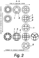
- Different alternatives are shown in Figure 2 , where the topmost row depicts means producing a point-form friction surface, which are not advantageous, for the reasons disclosed above, for example, in bone extension devices, because when constructed in the space available, their operation has proven unsatisfactory.
- the example in the third row depicts four barrel-shaped wedging effect providing meansor rolls. If barrel-shaped rolls are used, for example, with six or more rolls, an essentially round outer tube can be used.
- a part comprising a separate slanted plane makes it possible to work the slanted parts which wedge the balls or rolls separately, for example, by means of laser or water cutting or chasing.
- the separate part is only subjected to compressive forces and to some extent shearing forces, but hardly any tensile stress.
- the separate part can thus be made of a material which is optimal for use as a wedging slanted plane, which separate part can also be constructed in such a way that the slanted planes or counterparts of the wedge are constructed of separate smaller pieces, for example, by making only the slanted parts supporting the rolls or balls, for example, of tungsten carbide or titanium nitride, in which case they can be, for example, welded ultrasonically to a thin metal sheet which acts as a part supporting the rolls, balls or wedges and keeping them in place.
- the parts can be welded directly on the inner rod or outer tube.
- a round rod as a rod 1 in such a way that the separate parts are fitted on the surface of the rod, in which case the slanted surfaces are thus on the inner rod and lock the friction surfaces on the surface of the outer tube.
- the slanted surfaces are thus on the inner rod and lock the friction surfaces on the surface of the outer tube.
- barrel-shaped rolls the longitudinal curvature of which corresponds to the curvature of the inner surface of the outer tube.
- the inner tube are in this case fitted separate parts comprising slanted surfaces either in such a way that they rest directly on the round rod or that straight mating surfaces are bevelled for them.
- the advantage is easier workability of the inner rod itself, whereby the parts comprising special-shaped slanted surfaces can be made, for example, in large series by casting.
- the separate part may preferably be rectangular or also a circular arch in cross-section, in which case its mating surface is the outer surface of the rod or the inner surface of the tube.
- the separate part may then be, for example, a tubular part made of metal sheet, possibly left open, which clamps onto the inner rod or outer tube by means of its own spring force. I this case the separate part is thus preferably made straight and rolled into a slightly larger or smaller open tube than its mating surface so that it settles tightly on its mating surface.
- the final formation against the outer tube or inner tube takes place only when forced by the balls, rolls or wedges.
- the separate part may be, for example, a thin steel plate with parts holding sintered balls, or the separate part is a plate with holes or cavities for balls. The separate part does not move with respect to its base during operation.
- the separate pieces are locked, for example, by means of the stopper of Figure 1 , in the longitudinal direction and at the same time, also during locking, the frictional force keeps the parts in place against the surface of the outer part.
- the advantage of the separate part comprising a circular segment is that a round tube can be used on the inner or outer surface, or grooves having the correct cross-sectional shape can be worked for the balls on separate rails or, for example, in hard metal pieces comprising slanted grooves wedging the rolls, which are further welded or soldered on a tubular, longitudinally open sleeve holding them, which finally tightens against the surface when pressed by the locking means.
- the slanted surface can be made, for example, of ceramics or tungsten carbide, and its support and other parts, for example, of stainless steel or titanium.
- a hard and compression-resistant material can be used against the roll.
- the second mating surface of the roll or sprag is thus less resilient and more durable than when made of one material.
- the second mating surface is mobile and thus its plastic deformation is less disadvantageous, because in each operating cycle the roll presses a new point and the counter-tube of the device does not have to be used many times, because the device is usually patient-specific and the mechanics are, therefore, usually for single use only.
- the separate part may be a thin metal strip or a thin strip also comprising vertical walls on which the spring means can rest.
- the spring means may be, for example, a metal spring or a polymer spring which at the same time acts as an adhesive during assembly.
- Figure 4 shows various alternative structures for internal and external locking devices operating with rolls, balls or barrel-shaped pieces.
- Figure 2 shows different alternatives of section A-A.
- Figure 5 shows different sprag constructions.
- there may also be several springs for the sprags in which case the plastic deformations formed in the structure do not generate biasing forces of different magnitudes to the wedges biased with a joint spring.
- There may also be springs between the wedges in which case the spring may be thin and have a small length of stroke, whereby it allows a small angular difference between the wedges without the wedges losing their biasing force.
- there may be springs on both sides, in which case the different ends of the wedge are biased in different directions.
- Each wedge may also have a shaped mating surface at the immobile end.
- the rolls 3 may be adhered by means of a polymer bead to the stationary intermediate walls or the base of the unattached parts and possibly also to the wedge parts.
- the roll presses the polymer acting as a spring and the polymer generates a force which presses the roll tightly against the slanted surface.
- Between the roll and the polymer may be a separating support means which transmits the force of the spring.
- the spring may also be of metal.
- successive wedges or rolls can be mounted in successive mounting frames which are pressed together without clearance during mounting.
- the wedges or rolls of the rod or tube acting on the same face are in a different mounting frame, but the opposite means acting on the same point of the rod or tube may preferably be in the same mounting frame.
- the mounting frames are pressed into their final position successively in such a way that there is no significant clearance between them. During operation, no significant forces are exerted on the frames to separate them and thus the absence of clearance is easy to achieve provided that the faces of the mounting frames resting on one another are smooth and straight.
- each of the rolls in a group has its own biasing spring which is arranged in such a way that the spring allows the rolls to be mounted in the mounting frame in connection with the assembly of the device, one mounting frame at a time, and then moving the mounting frames in one direction by moving them without clearance into their final position, where they are pressed or connected in succession, whereupon the successive mounting frames together form several successive locking means in the direction of movement.
- the springs may be welded to the mounting frames in advance, in which case, when assembling the mounting frame on the rod, the rolls can be passed from a gap between the end of the rod and the spring, or the rolls can be kept in place before mounting by means of a suitable tool which keeps the rolls in place until the rod or tube keeps them in their final position.
- the tool may be, for example, a device in the shape of a locking rod, possibly additionally with means supporting the rolls which keep the rolls in place even if the rod and the tool are not completely in line during mounting.
- the supports may be, for example, spring-loaded pushers which extend at least to the end of the tool in such a way that even if the tool is moved slightly sideways, the rolls remain firmly pressed in place until the front edge of the bar supports the rolls in place and displaces the supports.
- the tool may also comprise means for keeping the rolls in place during mounting, in which case the rolls are placed on the tool and the tool is pushed into the mounting frame, whereupon the springs of the mounting frame stop the rolls in place when pushing the tool inside the mounting frame. After this, the mounting tool is pushed with the rod through the mounting frame and the rolls lock the mounting frame to the end of the rod.
- the rolls remain on the springs of the mounting frame, which is positioned spring downwards, by the effect of gravity.
- the mounting frame and the spring are then placed horizontally, for example on a table, in such a way that the spring is against the table. After this, the rolls are set in place on the springs, under the peak formed by the angle of the wedge plane.
- the locking means is picked up on the rod by pressing the rod between the rolls in contact with the table. The springs are thus biased very uniformly on all sides and mounting is quick and easy.
- the locking plane remains fixed right at the tip of the rod because the free direction of movement is from the table upwards.
- the following mounting frame can be mounted in a corresponding manner on the rod, whereby the frames settle in succession on the rod.
- the inner locking means can be mounted inside the tube in a corresponding manner, one at a time, in succession.
- the springs supporting the rolls are preferably plate-like torsion springs which can be welded into place in the body, or the springs can also be constructed so as to act as a locking ring, in which case for example springs with four rolls are parts of the same locking ring and the entire ring locks with spring force in a suitable groove or in clamps. If the spring is not welded, but is an unattached part at the assembly stage, the assembly can be carried out by mounting the spring only after the mounting frame and rolls.
- the advantages of the torsion spring are simplicity and flatness.
- a spring made of a steel strip is in addition durable and slippery and does not interfere unnecessarily with the turning of the roll.
- a spring can also be used, for example, an undulated spring washer, which also functions as a torsion spring, but rests on the opposite surface, that is, for example the next mounting frame.
- the mounting frames and their springs can also be constructed in such a way that they will also keep the rolls or wedges of even an unattached mounting frame in place.
- either the support or the spring can be designed to hold the rolls.
- the support may be, for example, a ring which is wedged on the wedge surface behind the rolls, or the support may be a fixed part of the mounting frame. In order for the roll to remain in place, the contact surfaces of the spring and the support with the roll must be further than within the radius of the roll from the wedge surface.
- the support may also have a cup-like shape.
- the support may also be removable once the mounting frame has been mounted in place.
- the removable support is preferably designed in such a way that it will not fit inside the device, but has to be removed in connection with the mounting.
- the removable support may be, for example, plastic.
- the mounting frames are preferably smooth and shiny at their end parts which are in contact with one another in order that no clearance is formed between them. By means of separate successive frames, the assembly is easier to carry out and the successive mounting frames are pressed tightly against one another during use because no pulling forces are exerted on them, and thus the separate frames do not reduce the strength and solidity of the device, because essentially only compressive force, and to some extent torsional forces, are exerted on the mounting frames externally, if the rest of the structure of the device does not receive them.
- the mounting frames can also be welded to one another in connection with the assembly to rigidify the structure.
- each mounting frame can preferably be made of one piece of material, they can be constructed to be extremely solid in the direction of the supporting forces of the locking means, in which case the clearance of a single locking means is as small as possible and there are no joints in the direction of the force generated by highest force of the locking means, that is, the force generated by the wedge surface or the sprag.
- the simplest mounting frame is the shape of a thick ring, there are slanted wedge surfaces for the rolls in the hole for the rod, and there may be a mounting recess for the springs, which gives them suitable flexibility. The recess giving flexibility may also be in the next mounting frame. In the frame are not needed any such parts that are not otherwise needed in the device. For example, compared with Figure 1 , the mounting frame may be considerably shorter and no stopper is required. Furthermore, a torsion spring takes up less space than a polymer spring. It is possible to make the mounting frame only slightly longer than the diameter of the rolls.
- a suitable adhesive may be, for example, a resilient biocompatible silicone plastic which later acts also as a spring generating the bias force for the rolls or wedges.
- silicone is used to glue the rolls on the slanted surface in such a way that the gluing simultaneously acts as a pressure spring during later operation.
- the back of the wedge then has to be shaped or roughened in such a way that the gluing or plastic casting will remain reliably fixed to the wedge part.
- the roll or sprag itself may detach from the gluing as soon as the assembly of the device has been completed. It is also possible to use, for example, water ice for temporary joining, which is easy to remove after the assembly by heating. In that case, the spring force must be generated in a different manner.
- the support part may be temporarily connected to the roll for the duration of the assembly or the support part may also be, for example, mounted on a bearing at the end of the roll. If a sprag is used, the sprags can be glued with the resilient material acting as a spring in such a way that the gluing keeps the wedges almost in place at one end and at the same time generates biasing force during use. In such a case, a suitably designed counterpart can be used for the wedges.
- the rolls are glued with a resilient polymer on a slanted surface or a support structure, they may also act as non-rotating wedges. In that case the position of the rolls will not change during operation, but when the locking is released, the polymer spring will return the position of the roll, which has twisted somewhat during locking, close to the original. The roll will thus probably become slightly flat on its friction surfaces during use, if plastic deformation or wear occurs in the roll.
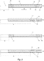
- FIG 3 shows different positions of the means allowing unidirectional movement.
- the means 19 allowing unidirectional movement are at different ends of a Terfenol means 11.
- the maximum path S is shorter than when the means 19 are on the same side, as in the second and fourth Figures (B and D).
- the locking friction surfaces 14 of the first two applications (A and B) are against the inner telescopic tube or rod 1 and friction surfaces 14 of the last two applications (C and D) act against the outer tube 12.
- Means arranged on the same side require an additional intermediate wall or support in the construction and thus the construction becomes somewhat more complex.
- the rolls or wedges may only be on one side of the means moving in one direction.
- the roll or wedge will then press the moving means against the friction surface on the opposite side.
- the wedge or roll has to withstand much greater surface pressure than the frictional surface of a backing having a larger surface area.
- the wedging angle of the wedge or roll must be sufficient for locking the wedge or roll, but there does not have to be more than one wedge or roll. This is preferable not only from the point of view of manufacturing costs, but also because there will be deformation on only one side and thus high surface pressures causing clearance.
- This solution also makes possible a semicircular cross-section, in which case the friction surface of the backing is curved.
Description
- The invention relates to the details of an implantable treatment device, especially to means allowing unidirectional movement, by means of which the short movement of a material generating reciprocating motion is converted into unidirectional long movement.
- Prior art is represented, for example, by the same applicant's earlier application
FI20085238 -
- The aim of the invention is to provide a device suitable for implantable use which functions even better, by means of which a change in the distance between two attachment points can be achieved with repeated changes in the length of intelligent material. Achieving sufficient power generation from the short reciprocating motion provided by the magnetostrictive material has proven to be a problem in connection with the above-mentioned application. The means allowing unidirectional movement and the clearances of the entire device must be smaller than the change in length effected by the magnetostrictive material when sufficient power is generated.
- Magnetostrictive material is advantageous because it provides sufficient power, for example, in bone extension treatment. The small length of the reciprocating motion generated is, however, a problem, whereby high demands are made on the means allowing unidirectional movement. Magnetostrictive material does not require any electronics around it. Thermal memory metal, such as Nitinol, requires heating means and a power feed and control means for them. MSM (Magnetic Shape Memory) materials generate a larger movement than magnetostrictive materials, but their power generation is insufficient without mechanical transmission. A piezoelectric actuator, on the other hand, requires, for example, an induction coil to generate the required voltage. All of the above intelligent materials can, however, be used in connection with the present invention with limitations.
- The distraction osteogenesis application according to the invention generally requires the following of power transmission:
- (1) The movement must be carried out in a controlled manner in steps of 0.25 mm (0.25 mm four times per day, that is, 1.0 mm/day).
- (2) The power transmission must transmit the power required for the distraction.
- (3) The movement must be locked after the step.
- (4) The locking must withstand the static and dynamic mechanical stress transmitted from the limb.
- In addition, the selected treatment method, that is, medullary nailing, sets special requirements:
- (5) Power transmission must fit inside the medullary nail.
- (6) The materials used must be biocompatible or their sufficient isolation from the body must be possible.
- With Terfenol-D, a reciprocating, repeated motion of about 0.15 mm is achieved during the extension treatment of a leg. This corresponds to a 0.12 % length extension with the counterforce required for treatment. Terfenol is brittle and thus no twisting, turning or cutting forces may be exerted on it. In the light of current knowledge, most patients could be treated with an extension force of approximately 800 N. At lowest, extension has been achieved with 300 N, but at highest, the force required has been 1400 N. In connection with the extension treatment of leg bones, the maximum forces normally occurring during the use of the device are in turn of the order of 2.5 times the weight of the patient. The strain exerted on the device when the patient walks is at its greatest at the final stage of treatment when the telescope of the nail is at its longest and the length of the telescope is no longer increased, and the friction surfaces of the mechanism thus remain in place and the strain is exerted on the same point for several months. The healed bone and the leg muscles quite soon take on a large proportion of the longitudinal strain, whereupon mainly forces resisting torsion remain for the device to support.
- In the earlier application was disclosed the use of a combination of a ball nut and a freewheel clutch and, for example, the use of barbs as means for allowing unidirectional movement. Furthermore, the publication
US2009076597 (paragraph 0022Fig. 2C ) discloses the use of a clutch operated by wedging balls in connection with an orthopaedic or similar device. The application does not disclose a bone extension device, but applications in which the forces required are considerably lower. - The round wedging balls generate a high surface pressure which causes elastic and plastic deformation in parts of the clutch. This in turn forms a clearance in the clutch, which is the greater the higher the force to be resisted by one ball. Since the space available is extremely limited, large balls do not fit in the device, nor does a large number of ball clutches. The solution described in
US2009076597 is, therefore, unsuitable for an application in which the forces are high and the space available is limited. The solution does not function in a bone distraction device, at least not when made of the usual materials, for example the materials conventionally used in ball bearings are not sufficiently durable for the device to withstand the strain for the duration of the whole treatment. - The present invention is characterized by the features defined in the characterizing part of the
independent claim 1. - According to the invention, the wedging effect providing means making line contact is used for locking the return movement of a unidirectional means. This wedging effect providing means may be, for example, a roll or a sprag. A ball or a barrel-shaped means is also possible if its mating surfaces are appropriately designed.
On the basis of tests carried out by the inventor, several successive clutches allowing unidirectional movement reduce the clearance subject to strain and with a suitable implementation, the amount of the clearance is almost inversely proportional to the number of the means. The solutions according to the invention are described in greater detail in the following, by means of the accompanying drawings. - Figure 1
- shows an embodiment of the means of the device according to the invention allowing unidirectional movement.
- Figure 2
- shows different cross-sections for the device allowing unidirectional movement.
- Figure 3
- shows different configurations for positioning the means allowing unidirectional movement.
- Figure 4
- shows views in principle of a freewheel operating on rolls.
- Figure 5
- shows the principle of a sprag clutch with linear movement.
-
Figure 1 shows an exploded view of a device allowing unidirectional movement. The device may preferably comprise several wedging effect providing members in succession. In the Figure, therod 1 moves inside thebody 2, therolls 3 rest on theslanted surfaces 7 pushed by aresilient plate 4 acting as a spring when thestopper 5 is screwed in place. When the rod is moved against the direction indicated by the arrow, theslanted surfaces 7 press therolls 3 against the faces 8 of the rod, whereupon the rolls lock the rod in place. Several successive wedges or rolls may be constructed, for example, in such a way that the successive parts which wedge the rolls or balls at an inclined or slanted angle with respect to the direction of travel of the periphery are worked on joint unattached pieces which fit on the mating surface of the outer or inner part of the device. Theslanted surfaces 7 are then worked into strips and several successive rolls are arranged on them. A spring is in this case provided for each roll, whereby the spring may rest on the surfaces of the strips or the springs may be pushed by means of thestopper 5 with means which extend, for example, beyond the space between the ends of therolls 3. As a spring may also be used a polymer, for example, biocompatible silicone rubber, with which the rolls are glued in place on the separate strips. - In the preferred embodiment of
Figure 1 is used anangular rod 1 having, for example, a rectangular cross-section, on which the rolls rest pressed by themeans 4 acting as a spring in such a way that the spring presses the rolls into the gap between the slanted surface and the rod. This spring means may be, for example, a biocompatible foamed plastic sheet or, for example, a silicone rubber spring made of a polymer, or a metal spring. A metal spring may be a bent, sheet-like coil spring, cup spring, etc. From the point of view of manufacturing technique, it is easiest to make the rod comprise surfaces which are straight in cross-section, because in that case the rolls or sprags are of uniform thickness and easy to manufacture. The rolls may also be, for example, barrel-shaped, but in that case the mating surfaces must be made concave. A barrel-shaped roll or a sprag having a friction surface in the shape of a circular arch makes possible line contact also with the inner surface of a round outer tube. In that case, however, the counterpart on the inner rod must be designed so as to be concave so that its radius of curvature will be the same as that of the outer tube. The concave and slanted mating surface can be made as a separate piece or it can be worked, for example, on the surface of the angular central rod. - Instead of straight rolls can also be used wedges, balls or barrel-shaped rolls. Different alternatives are shown in
Figure 2 , where the topmost row depicts means producing a point-form friction surface, which are not advantageous, for the reasons disclosed above, for example, in bone extension devices, because when constructed in the space available, their operation has proven unsatisfactory. The example in the third row depicts four barrel-shaped wedging effect providing meansor rolls. If barrel-shaped rolls are used, for example, with six or more rolls, an essentially round outer tube can be used. - Using a part comprising a separate slanted plane makes it possible to work the slanted parts which wedge the balls or rolls separately, for example, by means of laser or water cutting or chasing. Moreover, the separate part is only subjected to compressive forces and to some extent shearing forces, but hardly any tensile stress. The separate part can thus be made of a material which is optimal for use as a wedging slanted plane, which separate part can also be constructed in such a way that the slanted planes or counterparts of the wedge are constructed of separate smaller pieces, for example, by making only the slanted parts supporting the rolls or balls, for example, of tungsten carbide or titanium nitride, in which case they can be, for example, welded ultrasonically to a thin metal sheet which acts as a part supporting the rolls, balls or wedges and keeping them in place. Alternatively, the parts can be welded directly on the inner rod or outer tube. Using separate parts also makes it possible to use, for example, a round rod as a
rod 1 in such a way that the separate parts are fitted on the surface of the rod, in which case the slanted surfaces are thus on the inner rod and lock the friction surfaces on the surface of the outer tube. In this case can also be used barrel-shaped rolls, the longitudinal curvature of which corresponds to the curvature of the inner surface of the outer tube. In the inner tube are in this case fitted separate parts comprising slanted surfaces either in such a way that they rest directly on the round rod or that straight mating surfaces are bevelled for them. In both cases, the advantage is easier workability of the inner rod itself, whereby the parts comprising special-shaped slanted surfaces can be made, for example, in large series by casting. - The separate part may preferably be rectangular or also a circular arch in cross-section, in which case its mating surface is the outer surface of the rod or the inner surface of the tube. The separate part may then be, for example, a tubular part made of metal sheet, possibly left open, which clamps onto the inner rod or outer tube by means of its own spring force. I this case the separate part is thus preferably made straight and rolled into a slightly larger or smaller open tube than its mating surface so that it settles tightly on its mating surface. The final formation against the outer tube or inner tube takes place only when forced by the balls, rolls or wedges. The separate part may be, for example, a thin steel plate with parts holding sintered balls, or the separate part is a plate with holes or cavities for balls. The separate part does not move with respect to its base during operation.
- The separate pieces are locked, for example, by means of the stopper of
Figure 1 , in the longitudinal direction and at the same time, also during locking, the frictional force keeps the parts in place against the surface of the outer part. The advantage of the separate part comprising a circular segment is that a round tube can be used on the inner or outer surface, or grooves having the correct cross-sectional shape can be worked for the balls on separate rails or, for example, in hard metal pieces comprising slanted grooves wedging the rolls, which are further welded or soldered on a tubular, longitudinally open sleeve holding them, which finally tightens against the surface when pressed by the locking means. In this way is avoided the machining of several slanted cylindrical surfaces on the inner surface of the tube and the material of the slanted parts themselves may be selected freely. Thus, the slanted surface can be made, for example, of ceramics or tungsten carbide, and its support and other parts, for example, of stainless steel or titanium. Thus, a hard and compression-resistant material can be used against the roll. The second mating surface of the roll or sprag is thus less resilient and more durable than when made of one material. The second mating surface is mobile and thus its plastic deformation is less disadvantageous, because in each operating cycle the roll presses a new point and the counter-tube of the device does not have to be used many times, because the device is usually patient-specific and the mechanics are, therefore, usually for single use only. - Slanted surfaces are easier to work on a small separate part, because in that case sintering can also be used as well as techniques known from car tyre studs and the drill bits of rock drills. Also, for example, electrolytic growing and spark machining are easier to carry out on unattached parts than directly on the surface of a telescopic tube. The separate part may be a thin metal strip or a thin strip also comprising vertical walls on which the spring means can rest. The spring means may be, for example, a metal spring or a polymer spring which at the same time acts as an adhesive during assembly.
-
Figure 4 shows various alternative structures for internal and external locking devices operating with rolls, balls or barrel-shaped pieces.Figure 2 shows different alternatives of section A-A. -
Figure 5 shows different sprag constructions. Deviating fromFigure 5 , there may also be several springs for the sprags, in which case the plastic deformations formed in the structure do not generate biasing forces of different magnitudes to the wedges biased with a joint spring. There may also be springs between the wedges, in which case the spring may be thin and have a small length of stroke, whereby it allows a small angular difference between the wedges without the wedges losing their biasing force. Deviating from the Figure, there may be springs on both sides, in which case the different ends of the wedge are biased in different directions. Each wedge may also have a shaped mating surface at the immobile end. - The
rolls 3 may be adhered by means of a polymer bead to the stationary intermediate walls or the base of the unattached parts and possibly also to the wedge parts. When mounted, the roll presses the polymer acting as a spring and the polymer generates a force which presses the roll tightly against the slanted surface. Between the roll and the polymer may be a separating support means which transmits the force of the spring. The spring may also be of metal. - To facilitate assembly, successive wedges or rolls can be mounted in successive mounting frames which are pressed together without clearance during mounting. In that case, the wedges or rolls of the rod or tube acting on the same face are in a different mounting frame, but the opposite means acting on the same point of the rod or tube may preferably be in the same mounting frame. After assembly, the mounting frames are pressed into their final position successively in such a way that there is no significant clearance between them. During operation, no significant forces are exerted on the frames to separate them and thus the absence of clearance is easy to achieve provided that the faces of the mounting frames resting on one another are smooth and straight.
- There may be, for example, two or four rolls or wedges in one mounting frame, preferably two rolls acting on a flat rod, four rolls, that is, two opposite pairs acting on a rectangular rod. Alternatively, as a counter-pair of the roll can also be used a mere straight surface. Each of the rolls in a group has its own biasing spring which is arranged in such a way that the spring allows the rolls to be mounted in the mounting frame in connection with the assembly of the device, one mounting frame at a time, and then moving the mounting frames in one direction by moving them without clearance into their final position, where they are pressed or connected in succession, whereupon the successive mounting frames together form several successive locking means in the direction of movement.
- The springs may be welded to the mounting frames in advance, in which case, when assembling the mounting frame on the rod, the rolls can be passed from a gap between the end of the rod and the spring, or the rolls can be kept in place before mounting by means of a suitable tool which keeps the rolls in place until the rod or tube keeps them in their final position. The tool may be, for example, a device in the shape of a locking rod, possibly additionally with means supporting the rolls which keep the rolls in place even if the rod and the tool are not completely in line during mounting. The supports may be, for example, spring-loaded pushers which extend at least to the end of the tool in such a way that even if the tool is moved slightly sideways, the rolls remain firmly pressed in place until the front edge of the bar supports the rolls in place and displaces the supports. The tool may also comprise means for keeping the rolls in place during mounting, in which case the rolls are placed on the tool and the tool is pushed into the mounting frame, whereupon the springs of the mounting frame stop the rolls in place when pushing the tool inside the mounting frame. After this, the mounting tool is pushed with the rod through the mounting frame and the rolls lock the mounting frame to the end of the rod.
- If the springs have been shaped into suitably arched or inclined form before the springs are stressed, the rolls remain on the springs of the mounting frame, which is positioned spring downwards, by the effect of gravity. The mounting frame and the spring are then placed horizontally, for example on a table, in such a way that the spring is against the table. After this, the rolls are set in place on the springs, under the peak formed by the angle of the wedge plane. After this, once all rolls are in place, the locking means is picked up on the rod by pressing the rod between the rolls in contact with the table. The springs are thus biased very uniformly on all sides and mounting is quick and easy. The locking plane remains fixed right at the tip of the rod because the free direction of movement is from the table upwards. After this, the following mounting frame can be mounted in a corresponding manner on the rod, whereby the frames settle in succession on the rod. The inner locking means can be mounted inside the tube in a corresponding manner, one at a time, in succession.
- The springs supporting the rolls are preferably plate-like torsion springs which can be welded into place in the body, or the springs can also be constructed so as to act as a locking ring, in which case for example springs with four rolls are parts of the same locking ring and the entire ring locks with spring force in a suitable groove or in clamps. If the spring is not welded, but is an unattached part at the assembly stage, the assembly can be carried out by mounting the spring only after the mounting frame and rolls. The advantages of the torsion spring are simplicity and flatness. A spring made of a steel strip is in addition durable and slippery and does not interfere unnecessarily with the turning of the roll. As a spring can also be used, for example, an undulated spring washer, which also functions as a torsion spring, but rests on the opposite surface, that is, for example the next mounting frame.
- The mounting frames and their springs can also be constructed in such a way that they will also keep the rolls or wedges of even an unattached mounting frame in place. For this purpose, there is a support on the opposite side of the wedge surface of the rolls with respect to the springs, which prevents the roll from moving further. In addition, either the support or the spring can be designed to hold the rolls. The support may be, for example, a ring which is wedged on the wedge surface behind the rolls, or the support may be a fixed part of the mounting frame. In order for the roll to remain in place, the contact surfaces of the spring and the support with the roll must be further than within the radius of the roll from the wedge surface. The support may also have a cup-like shape. The support may also be removable once the mounting frame has been mounted in place. The removable support is preferably designed in such a way that it will not fit inside the device, but has to be removed in connection with the mounting. The removable support may be, for example, plastic.
The mounting frames are preferably smooth and shiny at their end parts which are in contact with one another in order that no clearance is formed between them. By means of separate successive frames, the assembly is easier to carry out and the successive mounting frames are pressed tightly against one another during use because no pulling forces are exerted on them, and thus the separate frames do not reduce the strength and solidity of the device, because essentially only compressive force, and to some extent torsional forces, are exerted on the mounting frames externally, if the rest of the structure of the device does not receive them. The mounting frames can also be welded to one another in connection with the assembly to rigidify the structure. - Since each mounting frame can preferably be made of one piece of material, they can be constructed to be extremely solid in the direction of the supporting forces of the locking means, in which case the clearance of a single locking means is as small as possible and there are no joints in the direction of the force generated by highest force of the locking means, that is, the force generated by the wedge surface or the sprag. The simplest mounting frame is the shape of a thick ring, there are slanted wedge surfaces for the rolls in the hole for the rod, and there may be a mounting recess for the springs, which gives them suitable flexibility. The recess giving flexibility may also be in the next mounting frame. In the frame are not needed any such parts that are not otherwise needed in the device. For example, compared with
Figure 1 , the mounting frame may be considerably shorter and no stopper is required. Furthermore, a torsion spring takes up less space than a polymer spring. It is possible to make the mounting frame only slightly longer than the diameter of the rolls. - To facilitate assembly, the many successive rolls can also be glued to the unattached parts with a biocompatible substance. A suitable adhesive may be, for example, a resilient biocompatible silicone plastic which later acts also as a spring generating the bias force for the rolls or wedges. In that case, for example, silicone is used to glue the rolls on the slanted surface in such a way that the gluing simultaneously acts as a pressure spring during later operation. In practice, the back of the wedge then has to be shaped or roughened in such a way that the gluing or plastic casting will remain reliably fixed to the wedge part. The roll or sprag itself may detach from the gluing as soon as the assembly of the device has been completed. It is also possible to use, for example, water ice for temporary joining, which is easy to remove after the assembly by heating. In that case, the spring force must be generated in a different manner.
- Between the roll or wedge and the polymer spring may be a separate support or bearing part which separates the spring and the roll from one another. This prevents the soft spring part from being twisted around the roll during use and thus the polymer from ending up between the friction surface. The support part may be temporarily connected to the roll for the duration of the assembly or the support part may also be, for example, mounted on a bearing at the end of the roll. If a sprag is used, the sprags can be glued with the resilient material acting as a spring in such a way that the gluing keeps the wedges almost in place at one end and at the same time generates biasing force during use. In such a case, a suitably designed counterpart can be used for the wedges. If the rolls are glued with a resilient polymer on a slanted surface or a support structure, they may also act as non-rotating wedges. In that case the position of the rolls will not change during operation, but when the locking is released, the polymer spring will return the position of the roll, which has twisted somewhat during locking, close to the original. The roll will thus probably become slightly flat on its friction surfaces during use, if plastic deformation or wear occurs in the roll.
- Other preferable spring materials are steel, cellular rubber or cellular plastic and Nitinol, which is a well-known superelastic and biocompatible material.
Figure 3 shows different positions of the means allowing unidirectional movement. In the first and third solutions (A and C), themeans 19 allowing unidirectional movement are at different ends of a Terfenol means 11. In this case, the maximum path S is shorter than when themeans 19 are on the same side, as in the second and fourth Figures (B and D). The locking friction surfaces 14 of the first two applications (A and B) are against the inner telescopic tube orrod 1 and friction surfaces 14 of the last two applications (C and D) act against theouter tube 12. Means arranged on the same side require an additional intermediate wall or support in the construction and thus the construction becomes somewhat more complex. - The rolls or wedges may only be on one side of the means moving in one direction. The roll or wedge will then press the moving means against the friction surface on the opposite side. This makes possible the use of different friction surfaces on the wedge or roll itself and its backing surface. The wedge or roll has to withstand much greater surface pressure than the frictional surface of a backing having a larger surface area. Also in that case, the wedging angle of the wedge or roll must be sufficient for locking the wedge or roll, but there does not have to be more than one wedge or roll. This is preferable not only from the point of view of manufacturing costs, but also because there will be deformation on only one side and thus high surface pressures causing clearance. This solution also makes possible a semicircular cross-section, in which case the friction surface of the backing is curved.
Claims (9)
- An implantable treatment device fixed or interlinked to bone, which generates unidirectional progressive movement by a member (11) generating reciprocating motion in the same direction by using friction based means (19) allowing unidirectional movement, the means (19) allowing unidirectional movement comprising a second member disposed adjacent to an inner rod (1) or an outer tube (2), the second member, or the inner rod or the outer tube, having a tapered portion having a slanted surface (7), wherein the tapered portion expands in the direction of movement of the inner rod or the outer tube, and wedging effect providing means (3) disposed between the slanted surface of the second member, or the inner rod or outer tube, and a planar surface of the second member, or the inner rod or outer tube, extending parallel to the direction of movement of the inner rod or outer tube, wherein the wedging effect providing means (3) provide wedging effect in cooperation with the slanted surface (7), characterised by the wedging effect providing means (3) being selected from a group comprising rolls, balls, barrel-shaped pieces or sprags forming a line contact with the second member or the inner rod or outer tube substantially non-parallel to the direction of movement.
- A device as claimed in claim 1, wherein the line contact of the wedging effect providing means (3) is perpendicular to the direction of movement.
- A device as claimed in claim 1 or 2, wherein there are several contact-making wedging effect providing means (3) in succession in the direction of movement of the unidirectional movement.
- A device as claimed in claim 1 or 3, wherein the tapered portion having a slanted surface is made as a separate part which is further connected to or rests by means of friction directly on its backing, or several counterparts of the balls, rolls, barrel-shaped pieces or sprags are attached to a common support part which is further connected to or supported on its backing.
- A device as claimed in claim 4, characterised in that several counterparts of the balls, rolls, barrel-shaped pieces or sprags are arranged in succession in the direction of movement on one or more separate support parts.
- A device as claimed in any of the above claims, wherein the member (11) generating the reciprocating motion comprises a magnetostrictive, memory metal, MSM or piezoelectric means.
- An intramedullary bone extension device comprising the device as claimed in any of the above claims.
- An extramedullary treatment device comprising the device as claimed in any of the above claims, for example, a treatment device for scoliosis or a chin distractor.
- An implantable device as claimed in claim 3, wherein groups of wedging effect providing means (3) successive in the direction of the movement of the unidirectional movement are each mounted in their own separate mounting frames in such a way that each wedge means has its own biasing spring and the mounting frames are suitable for being mounted one at a time successively on the inner rod (1) or the outer tube (2), whereby they can be moved, when the device is being assembled, in the direction of the allowed unidirectional movement to their final position along the rod or tube.
Priority Applications (1)
| Application Number | Priority Date | Filing Date | Title |
|---|---|---|---|
| PL11786188T PL2575654T3 (en) | 2010-05-24 | 2011-05-23 | Implantable treatment device fixed or interlinked to bone |
Applications Claiming Priority (2)
| Application Number | Priority Date | Filing Date | Title |
|---|---|---|---|
| FI20105569A FI123991B (en) | 2010-05-24 | 2010-05-24 | Intrinsic treatment device |
| PCT/FI2011/050465 WO2011148047A1 (en) | 2010-05-24 | 2011-05-23 | Implantable treatment device fixed or interlinked to bone |
Publications (3)
| Publication Number | Publication Date |
|---|---|
| EP2575654A1 EP2575654A1 (en) | 2013-04-10 |
| EP2575654A4 EP2575654A4 (en) | 2014-12-24 |
| EP2575654B1 true EP2575654B1 (en) | 2017-09-27 |
Family
ID=42234351
Family Applications (1)
| Application Number | Title | Priority Date | Filing Date |
|---|---|---|---|
| EP11786188.0A Active EP2575654B1 (en) | 2010-05-24 | 2011-05-23 | Implantable treatment device fixed or interlinked to bone |
Country Status (10)
| Country | Link |
|---|---|
| US (1) | US9474612B2 (en) |
| EP (1) | EP2575654B1 (en) |
| JP (1) | JP5909813B2 (en) |
| CN (1) | CN102933164B (en) |
| ES (1) | ES2653956T3 (en) |
| FI (1) | FI123991B (en) |
| NO (1) | NO2575654T3 (en) |
| PL (1) | PL2575654T3 (en) |
| RU (1) | RU2012155129A (en) |
| WO (1) | WO2011148047A1 (en) |
Families Citing this family (40)
| Publication number | Priority date | Publication date | Assignee | Title |
|---|---|---|---|---|
| US7955357B2 (en) | 2004-07-02 | 2011-06-07 | Ellipse Technologies, Inc. | Expandable rod system to treat scoliosis and method of using the same |
| US7862502B2 (en) | 2006-10-20 | 2011-01-04 | Ellipse Technologies, Inc. | Method and apparatus for adjusting a gastrointestinal restriction device |
| US20090112263A1 (en) | 2007-10-30 | 2009-04-30 | Scott Pool | Skeletal manipulation system |
| US11202707B2 (en) | 2008-03-25 | 2021-12-21 | Nuvasive Specialized Orthopedics, Inc. | Adjustable implant system |
| US11241257B2 (en) | 2008-10-13 | 2022-02-08 | Nuvasive Specialized Orthopedics, Inc. | Spinal distraction system |
| US8382756B2 (en) | 2008-11-10 | 2013-02-26 | Ellipse Technologies, Inc. | External adjustment device for distraction device |
| US8197490B2 (en) | 2009-02-23 | 2012-06-12 | Ellipse Technologies, Inc. | Non-invasive adjustable distraction system |
| US9622792B2 (en) | 2009-04-29 | 2017-04-18 | Nuvasive Specialized Orthopedics, Inc. | Interspinous process device and method |
| RU2016101629A (en) | 2009-09-04 | 2018-12-04 | Нувэйсив Спешилайзд Ортопэдикс, Инк. | DEVICE AND METHOD FOR BONE EXTENSION |
| US9248043B2 (en) | 2010-06-30 | 2016-02-02 | Ellipse Technologies, Inc. | External adjustment device for distraction device |
| WO2012021378A2 (en) | 2010-08-09 | 2012-02-16 | Ellipse Technologies, Inc. | Maintenance feature in magnetic implant |
| WO2012112396A2 (en) | 2011-02-14 | 2012-08-23 | Ellipse Technologies, Inc. | Device and method for treating fractured bones |
| US10743794B2 (en) | 2011-10-04 | 2020-08-18 | Nuvasive Specialized Orthopedics, Inc. | Devices and methods for non-invasive implant length sensing |
| US10016220B2 (en) | 2011-11-01 | 2018-07-10 | Nuvasive Specialized Orthopedics, Inc. | Adjustable magnetic devices and methods of using same |
| US9078711B2 (en) | 2012-06-06 | 2015-07-14 | Ellipse Technologies, Inc. | Devices and methods for detection of slippage of magnetic coupling in implantable medical devices |
| US20130338714A1 (en) | 2012-06-15 | 2013-12-19 | Arvin Chang | Magnetic implants with improved anatomical compatibility |
| US9044281B2 (en) | 2012-10-18 | 2015-06-02 | Ellipse Technologies, Inc. | Intramedullary implants for replacing lost bone |
| CA2889769A1 (en) | 2012-10-29 | 2014-05-08 | Ellipse Technologies, Inc. | Adjustable devices for treating arthritis of the knee |
| FI124970B (en) | 2013-02-22 | 2015-04-15 | Synoste Oy | Actuator and procedure for improving an actuator |
| US9179938B2 (en) | 2013-03-08 | 2015-11-10 | Ellipse Technologies, Inc. | Distraction devices and method of assembling the same |
| US10226242B2 (en) | 2013-07-31 | 2019-03-12 | Nuvasive Specialized Orthopedics, Inc. | Noninvasively adjustable suture anchors |
| US9801734B1 (en) | 2013-08-09 | 2017-10-31 | Nuvasive, Inc. | Lordotic expandable interbody implant |
| US10751094B2 (en) | 2013-10-10 | 2020-08-25 | Nuvasive Specialized Orthopedics, Inc. | Adjustable spinal implant |
| CN111345867A (en) | 2014-04-28 | 2020-06-30 | 诺威适骨科专科公司 | Remote control device |
| JP6672289B2 (en) | 2014-10-23 | 2020-03-25 | ニューベイシブ スペシャライズド オーソペディックス,インコーポレイテッド | Teleadjustable interactive bone remodeling implant |
| JP6847341B2 (en) | 2014-12-26 | 2021-03-24 | ニューベイシブ スペシャライズド オーソペディックス,インコーポレイテッド | Systems and methods for extension |
| US10238427B2 (en) | 2015-02-19 | 2019-03-26 | Nuvasive Specialized Orthopedics, Inc. | Systems and methods for vertebral adjustment |
| WO2017066774A1 (en) | 2015-10-16 | 2017-04-20 | Nuvasive Specialized Orthopedics, Inc. | Adjustable devices for treating arthritis of the knee |
| CN108601611B (en) | 2015-12-10 | 2021-11-02 | 诺威适骨科专科公司 | External adjustment device for a tensioning device |
| CN108882953B (en) | 2016-01-28 | 2021-09-03 | 诺威适骨科专科公司 | System for bone migration |
| WO2017139548A1 (en) | 2016-02-10 | 2017-08-17 | Nuvasive Specialized Orthopedics, Inc. | Systems and methods for controlling multiple surgical variables |
| FI20165445A (en) | 2016-05-27 | 2017-11-28 | Synoste Oy | Intra-body telescopic osteodystraction device, external body power generating device, method for bone extension and bone extension arrangement |
| US11039859B2 (en) * | 2016-07-28 | 2021-06-22 | Warsaw Orthopedic, Inc. | Spinal correction construct and method |
| CN109124747B (en) * | 2018-11-02 | 2023-08-25 | 山东中医药大学 | Fracture external fixation support with variable rigidity |
| EP3922039A1 (en) | 2019-02-07 | 2021-12-15 | NuVasive Specialized Orthopedics, Inc. | Ultrasonic communication in medical devices |
| US11589901B2 (en) | 2019-02-08 | 2023-02-28 | Nuvasive Specialized Orthopedics, Inc. | External adjustment device |
| AU2022225229A1 (en) | 2021-02-23 | 2023-09-21 | Nuvasive Specialized Orthopedics, Inc. | Adjustable implant, system and methods |
| CN112971995B (en) * | 2021-05-19 | 2021-08-31 | 成都博恩思医学机器人有限公司 | Separable manipulator device |
| US11737787B1 (en) | 2021-05-27 | 2023-08-29 | Nuvasive, Inc. | Bone elongating devices and methods of use |
| US20230270478A1 (en) * | 2022-02-25 | 2023-08-31 | Globus Medical, Inc. | Implantable osteodistraction device |
Citations (2)
| Publication number | Priority date | Publication date | Assignee | Title |
|---|---|---|---|---|
| US5415660A (en) * | 1994-01-07 | 1995-05-16 | Regents Of The University Of Minnesota | Implantable limb lengthening nail driven by a shape memory alloy |
| US5704939A (en) * | 1996-04-09 | 1998-01-06 | Justin; Daniel F. | Intramedullary skeletal distractor and method |
Family Cites Families (6)
| Publication number | Priority date | Publication date | Assignee | Title |
|---|---|---|---|---|
| US4453539A (en) | 1982-03-01 | 1984-06-12 | The University Of Toledo | Expandable intramedullary nail for the fixation of bone fractures |
| GB0106588D0 (en) * | 2001-03-16 | 2001-05-09 | Finsbury Dev Ltd | Tissue distracter |
| US7135022B2 (en) * | 2001-05-23 | 2006-11-14 | Orthogon 2003 Ltd. | Magnetically-actuable intramedullary device |
| EP1677692A1 (en) * | 2003-08-28 | 2006-07-12 | Wittenstein AG | Planetary roll system, in particular for a device for extending bones |
| US20090076597A1 (en) * | 2007-09-19 | 2009-03-19 | Jonathan Micheal Dahlgren | System for mechanical adjustment of medical implants |
| FI123247B (en) | 2008-03-19 | 2013-01-15 | Aalto Korkeakoulusaeaetioe | Intracorporeal bone distribution device |
-
2010
- 2010-05-24 FI FI20105569A patent/FI123991B/en not_active IP Right Cessation
-
2011
- 2011-05-23 EP EP11786188.0A patent/EP2575654B1/en active Active
- 2011-05-23 JP JP2013511710A patent/JP5909813B2/en active Active
- 2011-05-23 US US13/697,654 patent/US9474612B2/en active Active
- 2011-05-23 CN CN201180025392.1A patent/CN102933164B/en active Active
- 2011-05-23 ES ES11786188.0T patent/ES2653956T3/en active Active
- 2011-05-23 WO PCT/FI2011/050465 patent/WO2011148047A1/en active Application Filing
- 2011-05-23 NO NO11786188A patent/NO2575654T3/no unknown
- 2011-05-23 RU RU2012155129/14A patent/RU2012155129A/en not_active Application Discontinuation
- 2011-05-23 PL PL11786188T patent/PL2575654T3/en unknown
Patent Citations (2)
| Publication number | Priority date | Publication date | Assignee | Title |
|---|---|---|---|---|
| US5415660A (en) * | 1994-01-07 | 1995-05-16 | Regents Of The University Of Minnesota | Implantable limb lengthening nail driven by a shape memory alloy |
| US5704939A (en) * | 1996-04-09 | 1998-01-06 | Justin; Daniel F. | Intramedullary skeletal distractor and method |
Also Published As
| Publication number | Publication date |
|---|---|
| EP2575654A4 (en) | 2014-12-24 |
| NO2575654T3 (en) | 2018-02-24 |
| CN102933164B (en) | 2018-01-02 |
| EP2575654A1 (en) | 2013-04-10 |
| JP5909813B2 (en) | 2016-04-27 |
| RU2012155129A (en) | 2014-06-27 |
| WO2011148047A1 (en) | 2011-12-01 |
| PL2575654T3 (en) | 2018-06-29 |
| CN102933164A (en) | 2013-02-13 |
| US20140005788A1 (en) | 2014-01-02 |
| US9474612B2 (en) | 2016-10-25 |
| ES2653956T3 (en) | 2018-02-09 |
| FI20105569A (en) | 2011-11-25 |
| FI20105569A0 (en) | 2010-05-24 |
| FI123991B (en) | 2014-01-31 |
| JP2013526952A (en) | 2013-06-27 |
Similar Documents
| Publication | Publication Date | Title |
|---|---|---|
| EP2575654B1 (en) | Implantable treatment device fixed or interlinked to bone | |
| EP2959163B1 (en) | Actuator and method for improving an actuator | |
| US7407440B2 (en) | Drive shaft coupling | |
| CN101677830A (en) | Buffer type vertebral pedicle screw | |
| JP2010042253A (en) | Flexibility stabilizing device for connecting at least two bone fixing devices attachable to vertebrae of spine, its manufacturing method and tool for manufacturing flexibility stabilizing device | |
| EP0921767A1 (en) | Intramedullary, flexible fracture fixation device, using bi-axial prestressing | |
| WO2007014142A3 (en) | Ultrasonic transducer devices and methods of manufacture | |
| JP2008521565A5 (en) | ||
| US20220015751A1 (en) | Bone distraction devices and methods of using same | |
| CN104343187A (en) | Coupling member, method for producing coupling member, and wooden member joint structure | |
| JPH11159573A (en) | Manufacture of laminated rubber support body | |
| US20130289629A1 (en) | Bone Dowel | |
| CN201137659Y (en) | Disk-shape spring structure | |
| JP4120744B2 (en) | Member fastening method | |
| DK165992B (en) | HEAT-INSULATING, COMPOUND PROFILE AND PROCEDURE FOR PREPARING THE COMPOUND PROFILE | |
| JPWO2015125371A1 (en) | Pipe fastening body, treatment tool, and fastening method | |
| CN112057154B (en) | Femoral internal fixation system | |
| US20230190419A1 (en) | Fastener and method of installation | |
| CN110107588B (en) | Method for producing connecting rod | |
| WO2016193801A1 (en) | Tissue expansion booster | |
| Mirone et al. | SMA-activated nail for the fixation of long bone fractures | |
| MX2012008577A (en) | Closed clamp. | |
| Nasonov et al. | Application of dynamic method of intensive plastic deformation for obtaining the crystal structure in aluminium alloy AMts | |
| TWM411068U (en) | Motor buffering device of electric window and buffer ring thereof | |
| JP2002361358A (en) | Mold device |
Legal Events
| Date | Code | Title | Description |
|---|---|---|---|
| PUAI | Public reference made under article 153(3) epc to a published international application that has entered the european phase |
Free format text: ORIGINAL CODE: 0009012 |
|
| 17P | Request for examination filed |
Effective date: 20130102 |
|
| AK | Designated contracting states |
Kind code of ref document: A1 Designated state(s): AL AT BE BG CH CY CZ DE DK EE ES FI FR GB GR HR HU IE IS IT LI LT LU LV MC MK MT NL NO PL PT RO RS SE SI SK SM TR |
|
| DAX | Request for extension of the european patent (deleted) | ||
| RAP1 | Party data changed (applicant data changed or rights of an application transferred) |
Owner name: SYNOSTE OY |
|
| A4 | Supplementary search report drawn up and despatched |
Effective date: 20141126 |
|
| RIC1 | Information provided on ipc code assigned before grant |
Ipc: A61F 2/30 20060101ALI20141120BHEP Ipc: A61B 17/66 20060101ALI20141120BHEP Ipc: A61B 17/68 20060101ALI20141120BHEP Ipc: A61B 17/72 20060101AFI20141120BHEP |
|
| 17Q | First examination report despatched |
Effective date: 20151022 |
|
| GRAP | Despatch of communication of intention to grant a patent |
Free format text: ORIGINAL CODE: EPIDOSNIGR1 |
|
| INTG | Intention to grant announced |
Effective date: 20170510 |
|
| RIN1 | Information on inventor provided before grant (corrected) |
Inventor name: HAAJA, JUHA Inventor name: RITVANEN, ANTTI Inventor name: HALLILA, HARRI |
|
| GRAS | Grant fee paid |
Free format text: ORIGINAL CODE: EPIDOSNIGR3 |
|
| GRAA | (expected) grant |
Free format text: ORIGINAL CODE: 0009210 |
|
| AK | Designated contracting states |
Kind code of ref document: B1 Designated state(s): AL AT BE BG CH CY CZ DE DK EE ES FI FR GB GR HR HU IE IS IT LI LT LU LV MC MK MT NL NO PL PT RO RS SE SI SK SM TR |
|
| REG | Reference to a national code |
Ref country code: GB Ref legal event code: FG4D |
|
| REG | Reference to a national code |
Ref country code: CH Ref legal event code: EP |
|
| REG | Reference to a national code |
Ref country code: AT Ref legal event code: REF Ref document number: 931253 Country of ref document: AT Kind code of ref document: T Effective date: 20171015 |
|
| REG | Reference to a national code |
Ref country code: IE Ref legal event code: FG4D |
|
| REG | Reference to a national code |
Ref country code: DE Ref legal event code: R096 Ref document number: 602011041959 Country of ref document: DE |
|
| RAP2 | Party data changed (patent owner data changed or rights of a patent transferred) |
Owner name: SYNOSTE OY |
|
| REG | Reference to a national code |
Ref country code: NL Ref legal event code: FP |
|
| REG | Reference to a national code |
Ref country code: SE Ref legal event code: TRGR |
|
| PG25 | Lapsed in a contracting state [announced via postgrant information from national office to epo] |
Ref country code: LT Free format text: LAPSE BECAUSE OF FAILURE TO SUBMIT A TRANSLATION OF THE DESCRIPTION OR TO PAY THE FEE WITHIN THE PRESCRIBED TIME-LIMIT Effective date: 20170927 Ref country code: FI Free format text: LAPSE BECAUSE OF FAILURE TO SUBMIT A TRANSLATION OF THE DESCRIPTION OR TO PAY THE FEE WITHIN THE PRESCRIBED TIME-LIMIT Effective date: 20170927 Ref country code: HR Free format text: LAPSE BECAUSE OF FAILURE TO SUBMIT A TRANSLATION OF THE DESCRIPTION OR TO PAY THE FEE WITHIN THE PRESCRIBED TIME-LIMIT Effective date: 20170927 |
|
| REG | Reference to a national code |
Ref country code: ES Ref legal event code: FG2A Ref document number: 2653956 Country of ref document: ES Kind code of ref document: T3 Effective date: 20180209 |
|
| REG | Reference to a national code |
Ref country code: LT Ref legal event code: MG4D |
|
| REG | Reference to a national code |
Ref country code: NO Ref legal event code: T2 Effective date: 20170927 |
|
| PG25 | Lapsed in a contracting state [announced via postgrant information from national office to epo] |
Ref country code: RS Free format text: LAPSE BECAUSE OF FAILURE TO SUBMIT A TRANSLATION OF THE DESCRIPTION OR TO PAY THE FEE WITHIN THE PRESCRIBED TIME-LIMIT Effective date: 20170927 Ref country code: LV Free format text: LAPSE BECAUSE OF FAILURE TO SUBMIT A TRANSLATION OF THE DESCRIPTION OR TO PAY THE FEE WITHIN THE PRESCRIBED TIME-LIMIT Effective date: 20170927 Ref country code: BG Free format text: LAPSE BECAUSE OF FAILURE TO SUBMIT A TRANSLATION OF THE DESCRIPTION OR TO PAY THE FEE WITHIN THE PRESCRIBED TIME-LIMIT Effective date: 20171227 Ref country code: GR Free format text: LAPSE BECAUSE OF FAILURE TO SUBMIT A TRANSLATION OF THE DESCRIPTION OR TO PAY THE FEE WITHIN THE PRESCRIBED TIME-LIMIT Effective date: 20171228 |
|
| PG25 | Lapsed in a contracting state [announced via postgrant information from national office to epo] |
Ref country code: RO Free format text: LAPSE BECAUSE OF FAILURE TO SUBMIT A TRANSLATION OF THE DESCRIPTION OR TO PAY THE FEE WITHIN THE PRESCRIBED TIME-LIMIT Effective date: 20170927 |
|
| REG | Reference to a national code |
Ref country code: FR Ref legal event code: PLFP Year of fee payment: 8 |
|
| PG25 | Lapsed in a contracting state [announced via postgrant information from national office to epo] |
Ref country code: SK Free format text: LAPSE BECAUSE OF FAILURE TO SUBMIT A TRANSLATION OF THE DESCRIPTION OR TO PAY THE FEE WITHIN THE PRESCRIBED TIME-LIMIT Effective date: 20170927 Ref country code: SM Free format text: LAPSE BECAUSE OF FAILURE TO SUBMIT A TRANSLATION OF THE DESCRIPTION OR TO PAY THE FEE WITHIN THE PRESCRIBED TIME-LIMIT Effective date: 20170927 Ref country code: EE Free format text: LAPSE BECAUSE OF FAILURE TO SUBMIT A TRANSLATION OF THE DESCRIPTION OR TO PAY THE FEE WITHIN THE PRESCRIBED TIME-LIMIT Effective date: 20170927 Ref country code: IS Free format text: LAPSE BECAUSE OF FAILURE TO SUBMIT A TRANSLATION OF THE DESCRIPTION OR TO PAY THE FEE WITHIN THE PRESCRIBED TIME-LIMIT Effective date: 20180127 |
|
| REG | Reference to a national code |
Ref country code: DE Ref legal event code: R097 Ref document number: 602011041959 Country of ref document: DE |
|
| PG25 | Lapsed in a contracting state [announced via postgrant information from national office to epo] |
Ref country code: DK Free format text: LAPSE BECAUSE OF FAILURE TO SUBMIT A TRANSLATION OF THE DESCRIPTION OR TO PAY THE FEE WITHIN THE PRESCRIBED TIME-LIMIT Effective date: 20170927 |
|
| PLBE | No opposition filed within time limit |
Free format text: ORIGINAL CODE: 0009261 |
|
| STAA | Information on the status of an ep patent application or granted ep patent |
Free format text: STATUS: NO OPPOSITION FILED WITHIN TIME LIMIT |
|
| 26N | No opposition filed |
Effective date: 20180628 |
|
| PG25 | Lapsed in a contracting state [announced via postgrant information from national office to epo] |
Ref country code: SI Free format text: LAPSE BECAUSE OF FAILURE TO SUBMIT A TRANSLATION OF THE DESCRIPTION OR TO PAY THE FEE WITHIN THE PRESCRIBED TIME-LIMIT Effective date: 20170927 |
|
| PG25 | Lapsed in a contracting state [announced via postgrant information from national office to epo] |
Ref country code: MC Free format text: LAPSE BECAUSE OF FAILURE TO SUBMIT A TRANSLATION OF THE DESCRIPTION OR TO PAY THE FEE WITHIN THE PRESCRIBED TIME-LIMIT Effective date: 20170927 |
|
| PG25 | Lapsed in a contracting state [announced via postgrant information from national office to epo] |
Ref country code: LU Free format text: LAPSE BECAUSE OF NON-PAYMENT OF DUE FEES Effective date: 20180523 |
|
| PG25 | Lapsed in a contracting state [announced via postgrant information from national office to epo] |
Ref country code: MT Free format text: LAPSE BECAUSE OF NON-PAYMENT OF DUE FEES Effective date: 20180523 |
|
| PG25 | Lapsed in a contracting state [announced via postgrant information from national office to epo] |
Ref country code: HU Free format text: LAPSE BECAUSE OF FAILURE TO SUBMIT A TRANSLATION OF THE DESCRIPTION OR TO PAY THE FEE WITHIN THE PRESCRIBED TIME-LIMIT; INVALID AB INITIO Effective date: 20110523 Ref country code: PT Free format text: LAPSE BECAUSE OF FAILURE TO SUBMIT A TRANSLATION OF THE DESCRIPTION OR TO PAY THE FEE WITHIN THE PRESCRIBED TIME-LIMIT Effective date: 20170927 |
|
| PG25 | Lapsed in a contracting state [announced via postgrant information from national office to epo] |
Ref country code: CY Free format text: LAPSE BECAUSE OF FAILURE TO SUBMIT A TRANSLATION OF THE DESCRIPTION OR TO PAY THE FEE WITHIN THE PRESCRIBED TIME-LIMIT Effective date: 20170927 Ref country code: MK Free format text: LAPSE BECAUSE OF NON-PAYMENT OF DUE FEES Effective date: 20170927 |
|
| PG25 | Lapsed in a contracting state [announced via postgrant information from national office to epo] |
Ref country code: AL Free format text: LAPSE BECAUSE OF FAILURE TO SUBMIT A TRANSLATION OF THE DESCRIPTION OR TO PAY THE FEE WITHIN THE PRESCRIBED TIME-LIMIT Effective date: 20170927 |
|
| PGFP | Annual fee paid to national office [announced via postgrant information from national office to epo] |
Ref country code: IE Payment date: 20200407 Year of fee payment: 10 Ref country code: CH Payment date: 20200408 Year of fee payment: 10 Ref country code: NO Payment date: 20200408 Year of fee payment: 10 Ref country code: FR Payment date: 20200515 Year of fee payment: 10 Ref country code: TR Payment date: 20200512 Year of fee payment: 10 Ref country code: NL Payment date: 20200407 Year of fee payment: 10 Ref country code: CZ Payment date: 20200408 Year of fee payment: 10 |
|
| PGFP | Annual fee paid to national office [announced via postgrant information from national office to epo] |
Ref country code: SE Payment date: 20200408 Year of fee payment: 10 Ref country code: PL Payment date: 20200409 Year of fee payment: 10 Ref country code: IT Payment date: 20200407 Year of fee payment: 10 Ref country code: BE Payment date: 20200407 Year of fee payment: 10 |
|
| PGFP | Annual fee paid to national office [announced via postgrant information from national office to epo] |
Ref country code: AT Payment date: 20200407 Year of fee payment: 10 |
|
| PGFP | Annual fee paid to national office [announced via postgrant information from national office to epo] |
Ref country code: ES Payment date: 20200730 Year of fee payment: 10 |
|
| REG | Reference to a national code |
Ref country code: AT Ref legal event code: UEP Ref document number: 931253 Country of ref document: AT Kind code of ref document: T Effective date: 20170927 |
|
| REG | Reference to a national code |
Ref country code: NO Ref legal event code: MMEP |
|
| REG | Reference to a national code |
Ref country code: SE Ref legal event code: EUG |
|
| REG | Reference to a national code |
Ref country code: CH Ref legal event code: PL |
|
| REG | Reference to a national code |
Ref country code: NL Ref legal event code: MM Effective date: 20210601 |
|
| REG | Reference to a national code |
Ref country code: AT Ref legal event code: MM01 Ref document number: 931253 Country of ref document: AT Kind code of ref document: T Effective date: 20210523 |
|
| PG25 | Lapsed in a contracting state [announced via postgrant information from national office to epo] |
Ref country code: CZ Free format text: LAPSE BECAUSE OF NON-PAYMENT OF DUE FEES Effective date: 20210523 Ref country code: SE Free format text: LAPSE BECAUSE OF NON-PAYMENT OF DUE FEES Effective date: 20210524 Ref country code: NO Free format text: LAPSE BECAUSE OF NON-PAYMENT OF DUE FEES Effective date: 20210531 Ref country code: LI Free format text: LAPSE BECAUSE OF NON-PAYMENT OF DUE FEES Effective date: 20210531 Ref country code: AT Free format text: LAPSE BECAUSE OF NON-PAYMENT OF DUE FEES Effective date: 20210523 Ref country code: CH Free format text: LAPSE BECAUSE OF NON-PAYMENT OF DUE FEES Effective date: 20210531 |
|
| REG | Reference to a national code |
Ref country code: BE Ref legal event code: MM Effective date: 20210531 |
|
| PG25 | Lapsed in a contracting state [announced via postgrant information from national office to epo] |
Ref country code: IE Free format text: LAPSE BECAUSE OF NON-PAYMENT OF DUE FEES Effective date: 20210523 |
|
| PG25 | Lapsed in a contracting state [announced via postgrant information from national office to epo] |
Ref country code: NL Free format text: LAPSE BECAUSE OF NON-PAYMENT OF DUE FEES Effective date: 20210601 Ref country code: FR Free format text: LAPSE BECAUSE OF NON-PAYMENT OF DUE FEES Effective date: 20210531 |
|
| PG25 | Lapsed in a contracting state [announced via postgrant information from national office to epo] |
Ref country code: BE Free format text: LAPSE BECAUSE OF NON-PAYMENT OF DUE FEES Effective date: 20210531 |
|
| REG | Reference to a national code |
Ref country code: ES Ref legal event code: FD2A Effective date: 20220805 |
|
| PG25 | Lapsed in a contracting state [announced via postgrant information from national office to epo] |
Ref country code: ES Free format text: LAPSE BECAUSE OF NON-PAYMENT OF DUE FEES Effective date: 20210524 |
|
| PG25 | Lapsed in a contracting state [announced via postgrant information from national office to epo] |
Ref country code: PL Free format text: LAPSE BECAUSE OF NON-PAYMENT OF DUE FEES Effective date: 20210523 Ref country code: IT Free format text: LAPSE BECAUSE OF NON-PAYMENT OF DUE FEES Effective date: 20200523 |
|
| PGFP | Annual fee paid to national office [announced via postgrant information from national office to epo] |
Ref country code: DE Payment date: 20230530 Year of fee payment: 13 |
|
| PGFP | Annual fee paid to national office [announced via postgrant information from national office to epo] |
Ref country code: GB Payment date: 20230529 Year of fee payment: 13 |