EP2581402A1 - Wrinkle Reduction in Uncured Composite Laminates - Google Patents
Wrinkle Reduction in Uncured Composite Laminates Download PDFInfo
- Publication number
- EP2581402A1 EP2581402A1 EP20120197711 EP12197711A EP2581402A1 EP 2581402 A1 EP2581402 A1 EP 2581402A1 EP 20120197711 EP20120197711 EP 20120197711 EP 12197711 A EP12197711 A EP 12197711A EP 2581402 A1 EP2581402 A1 EP 2581402A1
- Authority
- EP
- European Patent Office
- Prior art keywords
- head
- wrinkles
- wrinkle
- layup
- transducer head
- Prior art date
- Legal status (The legal status is an assumption and is not a legal conclusion. Google has not performed a legal analysis and makes no representation as to the accuracy of the status listed.)
- Granted
Links
- 239000002131 composite material Substances 0.000 title claims abstract description 12
- 230000037331 wrinkle reduction Effects 0.000 title description 8
- 230000037303 wrinkles Effects 0.000 claims abstract description 114
- 238000000034 method Methods 0.000 claims description 63
- 238000003825 pressing Methods 0.000 claims description 8
- 230000001681 protective effect Effects 0.000 claims description 8
- 238000010438 heat treatment Methods 0.000 claims description 6
- 229920005989 resin Polymers 0.000 abstract description 15
- 239000011347 resin Substances 0.000 abstract description 15
- 239000000835 fiber Substances 0.000 abstract description 9
- 238000004519 manufacturing process Methods 0.000 description 13
- 239000012783 reinforcing fiber Substances 0.000 description 11
- 230000008569 process Effects 0.000 description 5
- 238000011946 reduction process Methods 0.000 description 4
- 238000010586 diagram Methods 0.000 description 3
- 239000003733 fiber-reinforced composite Substances 0.000 description 3
- 239000000463 material Substances 0.000 description 3
- 239000011159 matrix material Substances 0.000 description 3
- 230000004075 alteration Effects 0.000 description 2
- 230000008901 benefit Effects 0.000 description 2
- 239000011230 binding agent Substances 0.000 description 2
- 230000005284 excitation Effects 0.000 description 2
- 238000012423 maintenance Methods 0.000 description 2
- 230000009467 reduction Effects 0.000 description 2
- 238000010408 sweeping Methods 0.000 description 2
- 229920000049 Carbon (fiber) Polymers 0.000 description 1
- 239000004809 Teflon Substances 0.000 description 1
- 229920006362 Teflon® Polymers 0.000 description 1
- 230000002411 adverse Effects 0.000 description 1
- 239000004917 carbon fiber Substances 0.000 description 1
- 230000007613 environmental effect Effects 0.000 description 1
- 239000003822 epoxy resin Substances 0.000 description 1
- 239000004744 fabric Substances 0.000 description 1
- 239000011152 fibreglass Substances 0.000 description 1
- 230000010354 integration Effects 0.000 description 1
- 230000004048 modification Effects 0.000 description 1
- 238000012986 modification Methods 0.000 description 1
- 230000008520 organization Effects 0.000 description 1
- 229920000647 polyepoxide Polymers 0.000 description 1
- 238000009419 refurbishment Methods 0.000 description 1
- 230000003014 reinforcing effect Effects 0.000 description 1
- 230000003068 static effect Effects 0.000 description 1
- 239000003351 stiffener Substances 0.000 description 1
- 230000007704 transition Effects 0.000 description 1
Images


Classifications
-
- B—PERFORMING OPERATIONS; TRANSPORTING
- B29—WORKING OF PLASTICS; WORKING OF SUBSTANCES IN A PLASTIC STATE IN GENERAL
- B29C—SHAPING OR JOINING OF PLASTICS; SHAPING OF MATERIAL IN A PLASTIC STATE, NOT OTHERWISE PROVIDED FOR; AFTER-TREATMENT OF THE SHAPED PRODUCTS, e.g. REPAIRING
- B29C70/00—Shaping composites, i.e. plastics material comprising reinforcements, fillers or preformed parts, e.g. inserts
- B29C70/04—Shaping composites, i.e. plastics material comprising reinforcements, fillers or preformed parts, e.g. inserts comprising reinforcements only, e.g. self-reinforcing plastics
- B29C70/28—Shaping operations therefor
- B29C70/30—Shaping by lay-up, i.e. applying fibres, tape or broadsheet on a mould, former or core; Shaping by spray-up, i.e. spraying of fibres on a mould, former or core
-
- B—PERFORMING OPERATIONS; TRANSPORTING
- B29—WORKING OF PLASTICS; WORKING OF SUBSTANCES IN A PLASTIC STATE IN GENERAL
- B29C—SHAPING OR JOINING OF PLASTICS; SHAPING OF MATERIAL IN A PLASTIC STATE, NOT OTHERWISE PROVIDED FOR; AFTER-TREATMENT OF THE SHAPED PRODUCTS, e.g. REPAIRING
- B29C70/00—Shaping composites, i.e. plastics material comprising reinforcements, fillers or preformed parts, e.g. inserts
- B29C70/04—Shaping composites, i.e. plastics material comprising reinforcements, fillers or preformed parts, e.g. inserts comprising reinforcements only, e.g. self-reinforcing plastics
- B29C70/28—Shaping operations therefor
- B29C70/54—Component parts, details or accessories; Auxiliary operations, e.g. feeding or storage of prepregs or SMC after impregnation or during ageing
- B29C70/543—Fixing the position or configuration of fibrous reinforcements before or during moulding
-
- C—CHEMISTRY; METALLURGY
- C08—ORGANIC MACROMOLECULAR COMPOUNDS; THEIR PREPARATION OR CHEMICAL WORKING-UP; COMPOSITIONS BASED THEREON
- C08J—WORKING-UP; GENERAL PROCESSES OF COMPOUNDING; AFTER-TREATMENT NOT COVERED BY SUBCLASSES C08B, C08C, C08F, C08G or C08H
- C08J5/00—Manufacture of articles or shaped materials containing macromolecular substances
- C08J5/24—Impregnating materials with prepolymers which can be polymerised in situ, e.g. manufacture of prepregs
- C08J5/241—Impregnating materials with prepolymers which can be polymerised in situ, e.g. manufacture of prepregs using inorganic fibres
- C08J5/243—Impregnating materials with prepolymers which can be polymerised in situ, e.g. manufacture of prepregs using inorganic fibres using carbon fibres
-
- C—CHEMISTRY; METALLURGY
- C08—ORGANIC MACROMOLECULAR COMPOUNDS; THEIR PREPARATION OR CHEMICAL WORKING-UP; COMPOSITIONS BASED THEREON
- C08J—WORKING-UP; GENERAL PROCESSES OF COMPOUNDING; AFTER-TREATMENT NOT COVERED BY SUBCLASSES C08B, C08C, C08F, C08G or C08H
- C08J5/00—Manufacture of articles or shaped materials containing macromolecular substances
- C08J5/24—Impregnating materials with prepolymers which can be polymerised in situ, e.g. manufacture of prepregs
- C08J5/248—Impregnating materials with prepolymers which can be polymerised in situ, e.g. manufacture of prepregs using pre-treated fibres
-
- B—PERFORMING OPERATIONS; TRANSPORTING
- B29—WORKING OF PLASTICS; WORKING OF SUBSTANCES IN A PLASTIC STATE IN GENERAL
- B29C—SHAPING OR JOINING OF PLASTICS; SHAPING OF MATERIAL IN A PLASTIC STATE, NOT OTHERWISE PROVIDED FOR; AFTER-TREATMENT OF THE SHAPED PRODUCTS, e.g. REPAIRING
- B29C35/00—Heating, cooling or curing, e.g. crosslinking or vulcanising; Apparatus therefor
- B29C35/02—Heating or curing, e.g. crosslinking or vulcanizing during moulding, e.g. in a mould
- B29C35/0261—Heating or curing, e.g. crosslinking or vulcanizing during moulding, e.g. in a mould using ultrasonic or sonic vibrations
-
- B—PERFORMING OPERATIONS; TRANSPORTING
- B29—WORKING OF PLASTICS; WORKING OF SUBSTANCES IN A PLASTIC STATE IN GENERAL
- B29C—SHAPING OR JOINING OF PLASTICS; SHAPING OF MATERIAL IN A PLASTIC STATE, NOT OTHERWISE PROVIDED FOR; AFTER-TREATMENT OF THE SHAPED PRODUCTS, e.g. REPAIRING
- B29C35/00—Heating, cooling or curing, e.g. crosslinking or vulcanising; Apparatus therefor
- B29C35/02—Heating or curing, e.g. crosslinking or vulcanizing during moulding, e.g. in a mould
- B29C35/0266—Local curing
Definitions
- This disclosure generally relates to fabrication of composite laminates, and deals more particularly with a method for reducing wrinkles in uncured laminates.
- wrinkles may sometimes form in one or more of the plies. Wrinkling may be due to, without limitation, a ply being deformed during the layup process, and/or to relatively high friction between the reinforcing fibers caused by the tackiness of the uncured resin. Wrinkles are undesirable because they may result in voids or discontinuities in the cured laminate.
- wrinkles occurring in an uncured layup may be removed by applying heat and pressure to the wrinkles by manually "sweeping" the wrinkle using a hand tool that tends to flatten the wrinkle.
- This prior technique for removing wrinkles is time consuming, and in some cases, may be less than effective.
- Wrinkles formed in uncured laminates during the layup process may be substantially reduced or removed by subjecting the wrinkles to a combination of high frequency, low amplitude vibrations, and pressure.
- the wrinkle reduction process is effective and results in minimal adverse alteration or disturbance of reinforcing fibers.
- Wrinkle reduction in uncured laminates may be achieved in less time compared with prior hand sweeping techniques, lending the method to high rate manufacturing applications, and may require minimal specialized equipment to carry out the wrinkle reduction process.
- the disclosed method is particularly effective in reducing or removing wrinkles where plies of a layup have a tendency to bunch together, as in the case of hat stiffeners formed over ply transitions, the inner legs of drape form parts such as C and Z frames, and certain areas on I-shaped wing stringers for aircraft applications.
- reducing a wrinkle in a fiber reinforced prepreg resin ply comprises subjecting the wrinkle to vibrations.
- the wrinkle may be subjected to vibration by bringing a transducer head into contact with the ply, exciting the transducer to vibrate, and moving the transducer head over the wrinkle.
- the vibrations preferably have a high frequency and low amplitude.
- a protective sheet may be placed between the transducer head and the ply in order to protect the reinforcing fibers from deformation or alteration by the transducer head. Pressure may be applied to the wrinkle through the transducer head in order to enhance wrinkle reduction.
- reducing wrinkles in an uncured composite layup comprises: using a head to apply pressure to the layup in the area of the wrinkles; moving the head over the wrinkles as the pressure is being applied to the layup; and, applying vibrations to the wrinkles by vibrating the head as the pressure is being applied to the layup by the head.
- a sheet may be placed between the head and the layup in the area of the wrinkles in order to protect the reinforcing fibers in the layup, and pressure may be applied by the head to the layup by pressing the head against the sheet.
- the head may be excited using a high frequency, low amplitude signal.
- fabricating a composite aircraft subassembly comprises: forming a multi-ply fiber-reinforced composite layup wherein at least one of the plies includes a wrinkle; reducing the wrinkle by using a transducer head to apply pressure to at least one ply in the area of the wrinkle, moving the transducer head over the ply; exciting the transducer head to vibrate as the transducer head applies pressure to the at least one ply; compacting the layup; and, curing the layup.
- the method may further comprise covering the wrinkle with a smooth sheet by placing the smooth sheet over at least a portion of the layup, applying pressure to at least one ply by pressing the transducer head against the sheet; and then removing the sheet from the layup after the wrinkle has been reduced.
- an uncured composite laminate 20 comprises multiple plies 22 of fiber reinforced, prepreg material such as, without limitation, reinforcing carbon fibers held in an epoxy resin matrix.
- the reinforcing fibers in the plies 22 may be woven or knitted and may have any of a variety of fiber orientations. In some cases, some of the plies 22 may comprise unidirectional fibers pre-impregnated with resin.
- the laminate 20 may comprise for example, and without limitation, a layup 26 formed over tooling (not shown) used to shape the laminate 20 into a desired, composite structure.
- a layup 26 formed over tooling (not shown) used to shape the laminate 20 into a desired, composite structure.
- one or more wrinkles 24, also referred to as buckles or buckling may be formed in some or all of the plies 22. In some cases, the wrinkles 24 may be present in only the top one of the plies of the laminate 20.
- the wrinkles 24 may be caused by, without limitation, irregularities in the manner in which the individual plies 22 are laid up, or may be the result of uneven surface areas, angles, etc. forming part of the tooling (not shown). In any event, the tackiness of the resin used as a matrix to hold the reinforcing fibers may create friction between the reinforcing fibers 34 as well as friction between adjacent plies 22 that may prevent relaxation of the wrinkles 24. It should be noted here that while a laminate 20 comprising prepreg plies 22 has been illustrated, the disclosed method embodiments may also be used to reduce wrinkles in a dry preform that is later infused with resin, where the preform uses a resin binder that may encourage wrinkling of preform plies. It should also be noted that while the method embodiment has been illustrated in connection with the reduction of wrinkles in a multi-ply layup 26, the method may also be advantageously used to reduce wrinkles in a single ply.
- the wrinkles 24 may be reduced, or in some cases may be eliminated, by the application of high frequency, low amplitude vibrations to the surface 34 of the laminate 20 in the area of the wrinkles 24. Furthermore, the application of pressure simultaneous with the application of the vibrational energy to the wrinkles 24 may enhance reduction of the wrinkles 24.
- the vibrations are applied to the wrinkles 24 by means of a transducer head 28 having a smooth, lower face 30 that engages and applies pressure to the wrinkles 24 on the surface 34.
- the transducer head 28 may comprise a commercially available device that converts electrical power into vibrational energy that is amplified and focused at the face 30.
- the frequency and amplitude of the applied vibrations will vary depending upon the application and a variety of factors, including but not limited to the thickness of the laminate 20, the type of the resin matrix, the diameter of the reinforcing fibers, the size of the transducer head 28 and the level of applied power. In one typical application using a 1 inch transducer head operating at 600 Watts, a frequency of 35,000 Hz provided satisfactory results. In other applications, a frequency between 15,000 Hz and 70,000 Hz may provide satisfactory results.
- the range of suitable amplitudes may vary with the type and size of the transducer head 28, however, generally, an amplitude of between about 0.0005 and 0.005 inches may be suitable for a range of applications.
- the preferred type and size of the transducer head 28 may depend on the geometry of the wrinkle, the ply stack-up, ply thickness and the shape of the tooling.
- the sheet 36 may comprise, for example and without limitation, a Teflon ® coated fiberglass fabric such as Armalon ® having a substantially smooth upper surface 37.
- the sheet 36 may act to protect fibers in the top ply 22 from being deformed or otherwise disturbed by engagement with the moving face 30 of the transducer head 28.
- the sheet 36 may function to better distribute the pressure applied by the transducer head 28 to the surface 34 of the laminate 20, while the smooth upper surface 37 provides an interface between the wrinkle 24 and the transducer face 30 having less friction than the surface 34.
- the protective sheet 36 also eliminates resin build-up on the transducer face 30 that may otherwise occur if the transducer head 28 directly engaged the surface 34 of the laminate 20.
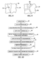
- FIG. 4 illustrates a wrinkle 24 that has been partially treated according to the disclosed embodiments. As illustrated in FIG. 4 , a section 38 of the wrinkle 24 has been substantially reduced and substantially eliminated by the simultaneous application of vibrational energy and pressure using the method described above.
- FIG. 5 illustrates the stacked relationship between the laminate 20, sheet 36 and transducer head 28.
- the sheet 36 is applied over the area of the wrinkle 24 which in this case, comprises the three upper plies designated by the numeral 45 which create a wrinkle 24.
- a downward pressure in the direction of the arrow 40 is applied by the transducer head 28 to the wrinkle 24 as vibrational energy is simultaneously applied.
- the high speed vibratory motion induced in the laminate plies 22 overcomes static friction in the uncured resin, permitting the fibers, which are typically arranged in bundles, to slip past each other and reduce wrinkle height.
- the vibratory motion may also create frictional heat in an amount sufficient to temporarily reduce the viscosity of the resin, thereby further encouraging relaxation of the wrinkle.
- heat gun not shown
- the applied heat should not be so great as to result in curing of the resin. Heating the wrinkle 24 may temporarily reduce the viscosity of the resin binder and thereby reduce friction between the reinforcing fibers which allows the wrinkle 24 to relax more readily.
- FIG. 6 illustrates the wrinkle 24 shown in FIG. 5 after treatment according to the disclosed method.
- the simultaneous application of high frequency, low amplitude vibrational energy and pressure allow the reinforcing fibers to slip relative to each other, resulting the flattening of the wrinkle 24.
- FIG. 6 depicts the wrinkle 24 as having been substantially reduced in height, in some applications the wrinkle may be essentially eliminated.
- the transducer head 28 may be mounted on the arm of a multi-axis robot (not shown) or an x,y,z stage (not shown) controlled by a computer (not shown) or a programmable logic controller (not shown).
- FIGS. 1-6 For convenience in describing the embodiments, the disclosed embodiments may also be used to reduce wrinkles having a variety of other shapes.
- the embodiments may be useful in reducing a generally bubble-shaped wrinkle 24a as shown in FIG. 7 , a tapered wrinkle 24b as shown in FIG. 8 , or intersecting wrinkles 24c as shown in FIG. 9 , to name only few.
- step 42 a plurality of prepreg plies 22 are laid up over suitable tooling (not shown).
- step 44 wrinkles present in the layup are located and optionally, at 46, the sheet 36 is placed over the upper surface of the layup.
- heat may be optionally applied to the wrinkle 24 either before (pre-heat) or during the wrinkle reduction process.
- step 50 the transducer head 28 is brought into pressure contact with the sheet 36, and pressure is applied to the layup through the sheet 36.
- step 52 a high frequency, low amplitude signal is applied to the transducer head 28, causing the latter to vibrate. Generally, these vibrations will be substantially normal to the surface 34 of the layup 24 (i.e., up and down), however they may have a lateral or oscillatory-like components.
- the transducer head 28 As pressure and vibrational energy is continued to be applied to the wrinkle 24, the transducer head 28 is moved across the wrinkle 24, as shown in step 54. Following the wrinkle reduction treatment described above, the wrinkles 24 may be inspected at 56, and if necessary the wrinkles may be retreated as shown at step 58. When the wrinkles 24 have been substantially reduced or eliminated, the transducer head 28 and protective sheet 36 may be removed at step 60, following which the layup may be compacted and cured in the normal manner, as shown at step 62.
- Embodiments of the disclosure may find use in a variety of potential applications, particularly in the transportation industry, including for example, aerospace, marine and automotive applications.
- exemplary method 64 may include specification and design 68 of the aircraft 66 and material procurement 70.
- component and subassembly manufacturing 72 and system integration 74 of the aircraft 66 takes place.
- the aircraft 66 may go through certification and delivery 76 in order to be placed in service 78.
- routine maintenance and service 80 (which may also include modification, reconfiguration, refurbishment, and so on).
- a system integrator may include without limitation any number of aircraft manufacturers and major-system subcontractors; a third party may include without limitation any number of vendors, subcontractors, and suppliers; and an operator may be an airline, leasing company, military entity, service organization, and so on.
- the aircraft 66 produced by exemplary method 64 may include an airframe 82 with a plurality of systems 84 and an interior 86.
- high-level systems 84 include one or more of a propulsion system 88, an electrical system 90, a hydraulic system 92, and an environmental system 94. Any number of other systems may be included.
- an aerospace example is shown, the principles of the disclosure may be applied to other industries, such as the marine and automotive industries.
- Systems and methods embodied herein may be employed during any one or more of the stages of the production and service method 64.
- components or subassemblies corresponding to production process 88 may be fabricated or manufactured in a manner similar to components or subassemblies produced while the aircraft 66 is in service.
- one or more apparatus embodiments, method embodiments, or a combination thereof may be utilized during the production stages 72 and 74, for example, by substantially expediting assembly of or reducing the cost of an aircraft 66.
- apparatus embodiments, method embodiments, or a combination thereof may be utilized while the aircraft 66 is in service, for example and without limitation, to maintenance and service 80.
Abstract
Description
- This disclosure generally relates to fabrication of composite laminates, and deals more particularly with a method for reducing wrinkles in uncured laminates.
- During the process of laying up multiple plies of uncured prepreg to form a composite laminate, wrinkles may sometimes form in one or more of the plies. Wrinkling may be due to, without limitation, a ply being deformed during the layup process, and/or to relatively high friction between the reinforcing fibers caused by the tackiness of the uncured resin. Wrinkles are undesirable because they may result in voids or discontinuities in the cured laminate.
- In the past, wrinkles occurring in an uncured layup may be removed by applying heat and pressure to the wrinkles by manually "sweeping" the wrinkle using a hand tool that tends to flatten the wrinkle. This prior technique for removing wrinkles is time consuming, and in some cases, may be less than effective.
- Accordingly, there is a need for a method of reducing or removing wrinkles from uncured fiber reinforced resin laminates that is rapid, effective and does not substantially alter the reinforcing fibers during the wrinkle reduction process.
- Wrinkles formed in uncured laminates during the layup process may be substantially reduced or removed by subjecting the wrinkles to a combination of high frequency, low amplitude vibrations, and pressure. The wrinkle reduction process is effective and results in minimal adverse alteration or disturbance of reinforcing fibers. Wrinkle reduction in uncured laminates may be achieved in less time compared with prior hand sweeping techniques, lending the method to high rate manufacturing applications, and may require minimal specialized equipment to carry out the wrinkle reduction process.
- The disclosed method is particularly effective in reducing or removing wrinkles where plies of a layup have a tendency to bunch together, as in the case of hat stiffeners formed over ply transitions, the inner legs of drape form parts such as C and Z frames, and certain areas on I-shaped wing stringers for aircraft applications.
- According to one disclosed method embodiment, reducing a wrinkle in a fiber reinforced prepreg resin ply comprises subjecting the wrinkle to vibrations. The wrinkle may be subjected to vibration by bringing a transducer head into contact with the ply, exciting the transducer to vibrate, and moving the transducer head over the wrinkle. The vibrations preferably have a high frequency and low amplitude. A protective sheet may be placed between the transducer head and the ply in order to protect the reinforcing fibers from deformation or alteration by the transducer head. Pressure may be applied to the wrinkle through the transducer head in order to enhance wrinkle reduction.
- In accordance with another method embodiment, reducing wrinkles in an uncured composite layup, comprises: using a head to apply pressure to the layup in the area of the wrinkles; moving the head over the wrinkles as the pressure is being applied to the layup; and, applying vibrations to the wrinkles by vibrating the head as the pressure is being applied to the layup by the head. A sheet may be placed between the head and the layup in the area of the wrinkles in order to protect the reinforcing fibers in the layup, and pressure may be applied by the head to the layup by pressing the head against the sheet. The head may be excited using a high frequency, low amplitude signal.
- According to a further method embodiment, fabricating a composite aircraft subassembly comprises: forming a multi-ply fiber-reinforced composite layup wherein at least one of the plies includes a wrinkle; reducing the wrinkle by using a transducer head to apply pressure to at least one ply in the area of the wrinkle, moving the transducer head over the ply; exciting the transducer head to vibrate as the transducer head applies pressure to the at least one ply; compacting the layup; and, curing the layup. The method may further comprise covering the wrinkle with a smooth sheet by placing the smooth sheet over at least a portion of the layup, applying pressure to at least one ply by pressing the transducer head against the sheet; and then removing the sheet from the layup after the wrinkle has been reduced.
- 10. A method of reducing wrinkles in an uncured composite layup, comprising:
- using a head to apply pressure to the layup in the area of the wrinkles;
- moving the head over the wrinkles as the pressure is being applied to the layup; and
- applying vibrations to the wrinkles by vibrating the head as the pressure is being applied to the layup by the head.
- 11. The method of claim 10, further comprising:
- protecting the layup by placing a sheet over the layup in the area of the wrinkles, and wherein
- the pressure is applied by the head to the layup by pressing the head against the sheet.
- 12. The method of claim 10, wherein vibrating the head includes exciting the head with a high frequency signal.
- 13. The method of claim 12, wherein exciting the head includes exciting the head with a signal having a frequency between approximately 15,000 Hz and 70,000 Hz.
- 14. The method of claim 10, wherein vibrating the head includes exciting the head with a low amplitude signal.
- 15. The method of claim 14, wherein exciting the head with a low amplitude signal includes applying a signal to the head having an amplitude between approximately 0.0005 inches and 0.005 inches.
- 16. The method of claim 11, wherein the sheet includes a substantially smooth protective surface against which the head is pressed.
- 17. The method of claim 10, further comprising:
- heating the ply at least in the area of the wrinkles.
- 18. A method of fabricating a composite aircraft subassembly, comprising:
- forming a multi-ply, fiber-reinforced composite layup, wherein at least one of the plies includes a wrinkle;
- reducing the wrinkle by -
using a transducer head to apply pressure to the at least one ply in the area of the wrinkle,
moving the transducer head over the ply,
exciting the transducer head to vibrate as the transducer head applies pressure to the at least one ply; - compacting the layup; and
- curing the layup.
- 19. The method of claim 18, further comprising:
- covering the wrinkle with a smooth sheet by placing the smooth sheet over at least a portion of the layup; and
- removing the sheet from the layup after the wrinkle has been reduced,
- wherein using a transducer head to apply pressure to the at least one ply includes pressing the transducer head against the sheet.
- 20. The method of claim 18, wherein exciting the transducer head to vibrate includes applying a high frequency excitation signal to the transducer head.
- 21. The method of
claim 20, wherein applying a high frequency excitation signal includes applying a signal having a frequency between approximately 15,000 Hz and 70,000 Hz. - 22. The method of claim 21, wherein the signal has a low amplitude.
- 23. The method of
claim 22, wherein the amplitude of the signal is between approximately 0.0005 inches and 0.005 inches. - 24. The method of claim 18, further comprising:
- heating the at least one ply in the area of the wrinkle.
- 25. A method of fabricating a composite aircraft subassembly, comprising:
- forming a multi-ply, fiber-reinforced composite layup, wherein the layup includes a wrinkle;
- reducing the wrinkle by -
placing a substantially smooth sheet over the layup covering the wrinkle,
bringing a transducer head into contact with the sheet,
applying pressure to the wrinkle by pressing the transducer head against the sheet in the area of the wrinkle,
moving the transducer head over the layup as the transducer head is being pressed against the sheet,
heating the layup in at least the area of the wrinkle;
exciting the transducer head to vibrate with a high frequency, low amplitude signal as the transducer head is being pressed against the sheet; - removing the sheet after the wrinkle has been reduced
- compacting the layup; and
- curing the layup.
- Other features, benefits and advantages of the disclosed embodiments will become apparent from the following description of embodiments, when viewed in accordance with the attached drawings and appended claims
-
-
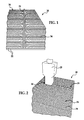
FIG. 1 is a perspective illustration of an uncured laminate having a wrinkle formed in upper plies thereof. -
FIG. 2 is a perspective illustration of the uncured laminate shown inFIG. 1 and further depicting a vibrating transducer head pressed against the wrinkle. -
FIG. 3 is a perspective illustration similar toFIG. 2 but showing a protective sheet having been placed between the transducer head and the laminate. -
FIG. 4 is a perspective illustration of the uncured laminate shown inFIGS. 2 and3 , wherein a portion of the wrinkle has been reduced. -
FIG. 5 is a sectional illustration taken along the line 5-5 inFIG. 3 . -
FIG. 6 is a cross sectional illustration of the laminate shown inFIG. 5 after the wrinkle has been reduced. -
FIGS. 7-9 are plan views illustrating exemplary forms of wrinkles that may be reduced according to the disclosed embodiments. -
FIG. 10 is a simplified flow chart illustrating the steps of a method for reducing wrinkles in an uncured laminate. -
FIG. 11 is a flow diagram of aircraft production and service methodology. -
FIG. 12 is a block diagram of an aircraft. - Referring to
FIG. 1 , an uncuredcomposite laminate 20 comprisesmultiple plies 22 of fiber reinforced, prepreg material such as, without limitation, reinforcing carbon fibers held in an epoxy resin matrix. The reinforcing fibers in theplies 22 may be woven or knitted and may have any of a variety of fiber orientations. In some cases, some of theplies 22 may comprise unidirectional fibers pre-impregnated with resin. - The laminate 20 may comprise for example, and without limitation, a
layup 26 formed over tooling (not shown) used to shape the laminate 20 into a desired, composite structure. During the layup process in which theplies 22 are successively stacked over the tooling (not shown), one ormore wrinkles 24, also referred to as buckles or buckling, may be formed in some or all of theplies 22. In some cases, thewrinkles 24 may be present in only the top one of the plies of the laminate 20. - The
wrinkles 24 may be caused by, without limitation, irregularities in the manner in which the individual plies 22 are laid up, or may be the result of uneven surface areas, angles, etc. forming part of the tooling (not shown). In any event, the tackiness of the resin used as a matrix to hold the reinforcing fibers may create friction between the reinforcingfibers 34 as well as friction betweenadjacent plies 22 that may prevent relaxation of thewrinkles 24. It should be noted here that while a laminate 20 comprising prepreg plies 22 has been illustrated, the disclosed method embodiments may also be used to reduce wrinkles in a dry preform that is later infused with resin, where the preform uses a resin binder that may encourage wrinkling of preform plies. It should also be noted that while the method embodiment has been illustrated in connection with the reduction of wrinkles in amulti-ply layup 26, the method may also be advantageously used to reduce wrinkles in a single ply. - In accordance with the disclosed embodiments, the
wrinkles 24 may be reduced, or in some cases may be eliminated, by the application of high frequency, low amplitude vibrations to thesurface 34 of the laminate 20 in the area of thewrinkles 24. Furthermore, the application of pressure simultaneous with the application of the vibrational energy to thewrinkles 24 may enhance reduction of thewrinkles 24. In one embodiment, the vibrations are applied to thewrinkles 24 by means of atransducer head 28 having a smooth,lower face 30 that engages and applies pressure to thewrinkles 24 on thesurface 34. - The
transducer head 28 may comprise a commercially available device that converts electrical power into vibrational energy that is amplified and focused at theface 30. The frequency and amplitude of the applied vibrations will vary depending upon the application and a variety of factors, including but not limited to the thickness of the laminate 20, the type of the resin matrix, the diameter of the reinforcing fibers, the size of thetransducer head 28 and the level of applied power. In one typical application using a 1 inch transducer head operating at 600 Watts, a frequency of 35,000 Hz provided satisfactory results. In other applications, a frequency between 15,000 Hz and 70,000 Hz may provide satisfactory results. The range of suitable amplitudes may vary with the type and size of thetransducer head 28, however, generally, an amplitude of between about 0.0005 and 0.005 inches may be suitable for a range of applications. The preferred type and size of thetransducer head 28 may depend on the geometry of the wrinkle, the ply stack-up, ply thickness and the shape of the tooling. - Referring now to
FIG. 3 , in some applications, it may be advantageous to place aprotective sheet 36 of material between thetransducer face 30 and thesurface 34 of the laminate 20. Thesheet 36 may comprise, for example and without limitation, a Teflon® coated fiberglass fabric such as Armalon® having a substantially smoothupper surface 37. Thesheet 36 may act to protect fibers in the top ply 22 from being deformed or otherwise disturbed by engagement with the movingface 30 of thetransducer head 28. Additionally, thesheet 36 may function to better distribute the pressure applied by thetransducer head 28 to thesurface 34 of the laminate 20, while the smoothupper surface 37 provides an interface between thewrinkle 24 and thetransducer face 30 having less friction than thesurface 34. Finally, theprotective sheet 36 also eliminates resin build-up on thetransducer face 30 that may otherwise occur if thetransducer head 28 directly engaged thesurface 34 of the laminate 20. - The
transducer head 28 may be moved over thewrinkles 24 in any of various directions, such as in line with the direction or orientation of thewrinkles 24 or traverse to such orientation.FIG. 4 illustrates awrinkle 24 that has been partially treated according to the disclosed embodiments. As illustrated inFIG. 4 , asection 38 of thewrinkle 24 has been substantially reduced and substantially eliminated by the simultaneous application of vibrational energy and pressure using the method described above. -
FIG. 5 illustrates the stacked relationship between the laminate 20,sheet 36 andtransducer head 28. Thesheet 36 is applied over the area of thewrinkle 24 which in this case, comprises the three upper plies designated by the numeral 45 which create awrinkle 24. A downward pressure in the direction of thearrow 40 is applied by thetransducer head 28 to thewrinkle 24 as vibrational energy is simultaneously applied. The high speed vibratory motion induced in the laminate plies 22 overcomes static friction in the uncured resin, permitting the fibers, which are typically arranged in bundles, to slip past each other and reduce wrinkle height. The vibratory motion may also create frictional heat in an amount sufficient to temporarily reduce the viscosity of the resin, thereby further encouraging relaxation of the wrinkle. - In some applications, it may be advantageous to also apply
additional heat 32 to thewrinkle 24 near thetransducer head 28 using a heat gun (not shown) or other suitable heat source, or to preheat theentire laminate 20, however, the applied heat should not be so great as to result in curing of the resin. Heating thewrinkle 24 may temporarily reduce the viscosity of the resin binder and thereby reduce friction between the reinforcing fibers which allows thewrinkle 24 to relax more readily. -
FIG. 6 illustrates thewrinkle 24 shown inFIG. 5 after treatment according to the disclosed method. The simultaneous application of high frequency, low amplitude vibrational energy and pressure allow the reinforcing fibers to slip relative to each other, resulting the flattening of thewrinkle 24. AlthoughFIG. 6 depicts thewrinkle 24 as having been substantially reduced in height, in some applications the wrinkle may be essentially eliminated. - In some high-rate production environments where wrinkles may tend to occur in the same general areas of a laminate 20, it may be desirable to automate the method of reducing wrinkles described above. For example, the
transducer head 28 may be mounted on the arm of a multi-axis robot (not shown) or an x,y,z stage (not shown) controlled by a computer (not shown) or a programmable logic controller (not shown). - It should be noted here that although a simple, linearly shaped
wrinkle 24 has been illustrated inFIGS. 1-6 for convenience in describing the embodiments, the disclosed embodiments may also be used to reduce wrinkles having a variety of other shapes. For example, the embodiments may be useful in reducing a generally bubble-shapedwrinkle 24a as shown inFIG. 7 , a tapered wrinkle 24b as shown inFIG. 8 , or intersectingwrinkles 24c as shown inFIG. 9 , to name only few. - The method of reducing wrinkles described above is further illustrated in the flow diagram of
FIG. 10 . Beginning atstep 42, a plurality of prepreg plies 22 are laid up over suitable tooling (not shown). Next at 44, wrinkles present in the layup are located and optionally, at 46, thesheet 36 is placed over the upper surface of the layup. In some applications, as shown in 48, heat may be optionally applied to thewrinkle 24 either before (pre-heat) or during the wrinkle reduction process. Atstep 50, thetransducer head 28 is brought into pressure contact with thesheet 36, and pressure is applied to the layup through thesheet 36. Atstep 52, a high frequency, low amplitude signal is applied to thetransducer head 28, causing the latter to vibrate. Generally, these vibrations will be substantially normal to thesurface 34 of the layup 24 (i.e., up and down), however they may have a lateral or oscillatory-like components. - As pressure and vibrational energy is continued to be applied to the
wrinkle 24, thetransducer head 28 is moved across thewrinkle 24, as shown instep 54. Following the wrinkle reduction treatment described above, thewrinkles 24 may be inspected at 56, and if necessary the wrinkles may be retreated as shown atstep 58. When thewrinkles 24 have been substantially reduced or eliminated, thetransducer head 28 andprotective sheet 36 may be removed atstep 60, following which the layup may be compacted and cured in the normal manner, as shown atstep 62. - Embodiments of the disclosure may find use in a variety of potential applications, particularly in the transportation industry, including for example, aerospace, marine and automotive applications. Thus, referring now to
FIGS. 11 and 12 , embodiments of the disclosure may be used in the context of an aircraft manufacturing andservice method 64 as shown inFIG. 11 and anaircraft 66 as shown inFigure 12 . During pre-production,exemplary method 64 may include specification anddesign 68 of theaircraft 66 andmaterial procurement 70. During production, component andsubassembly manufacturing 72 andsystem integration 74 of theaircraft 66 takes place. Thereafter, theaircraft 66 may go through certification anddelivery 76 in order to be placed inservice 78. While in service by a customer, theaircraft 66 is scheduled for routine maintenance and service 80 (which may also include modification, reconfiguration, refurbishment, and so on). - Each of the processes of
method 64 may be performed or carried out by a system integrator, a third party, and/or an operator (e.g., a customer). For the purposes of this description, a system integrator may include without limitation any number of aircraft manufacturers and major-system subcontractors; a third party may include without limitation any number of vendors, subcontractors, and suppliers; and an operator may be an airline, leasing company, military entity, service organization, and so on. - As shown in
FIG. 12 , theaircraft 66 produced byexemplary method 64 may include anairframe 82 with a plurality ofsystems 84 and an interior 86. Examples of high-level systems 84 include one or more of apropulsion system 88, anelectrical system 90, ahydraulic system 92, and anenvironmental system 94. Any number of other systems may be included. Although an aerospace example is shown, the principles of the disclosure may be applied to other industries, such as the marine and automotive industries. - Systems and methods embodied herein may be employed during any one or more of the stages of the production and
service method 64. For example, components or subassemblies corresponding toproduction process 88 may be fabricated or manufactured in a manner similar to components or subassemblies produced while theaircraft 66 is in service. Also, one or more apparatus embodiments, method embodiments, or a combination thereof may be utilized during the production stages 72 and 74, for example, by substantially expediting assembly of or reducing the cost of anaircraft 66. Similarly, one or more of apparatus embodiments, method embodiments, or a combination thereof may be utilized while theaircraft 66 is in service, for example and without limitation, to maintenance andservice 80. - Although the embodiments of this disclosure have been described with respect to certain exemplary embodiments, it is to be understood that the specific embodiments are for purposes of illustration and not limitation, as other variations will occur to those of skill in the art.
- The following items are disclosed.
- 1. A method of reducing a wrinkle in a fiber reinforced prepreg resin ply, comprising:
- subjecting the wrinkle to vibrations.
- 2. The method of item 1, wherein subjecting the wrinkle to vibration is performed by:
- bringing a transducer head into contact with the ply, exciting the transducer head to vibrate, and
- moving the transducer head over the wrinkle.
- 3. The method of item 2, wherein exciting the transducer head to vibrate includes exciting the transducer head to vibrate at high frequencies.
- 4. The method of item 3, wherein the transducer head is excited to vibrate at frequencies within a range of approximately 15,000 Hz and 70,000 Hz.
- 5. The method of item 2, wherein exciting the transducer head to vibrate includes exciting the transducer head to vibrate at low amplitude.
- 6. The method of item 4, wherein the transducer head is excited to vibrate with an amplitude between approximately 0.0005 inches and 0.005 inches.
- 7. The method of item 2, further comprising:
- using the transducer head to apply pressure to the wrinkle as the transducer head is moving over the wrinkle.
- 8. The method of item 2, further comprising:
- protecting the ply by placing a protective sheet between the transducer head and the wrinkle.
- 9. The method of item 2, further comprising:
- heating the ply in the area of the wrinkle.
Claims (8)
- A method of reducing wrinkles in an uncured composite layup, comprising:using a head to apply pressure to the layup in the area of the wrinkles;moving the head over the wrinkles as the pressure is being applied to the layup; andapplying vibrations to the wrinkles by vibrating the head as the pressure is being applied to the layup by the head.
- The method of claim 1, further comprising:protecting the layup by placing a sheet over the layup in the area of the wrinkles, and whereinthe pressure is applied by the head to the layup by pressing the head against the sheet.
- The method of claim 1, wherein vibrating the head includes exciting the head with a high frequency signal.
- The method of claim 3, wherein exciting the head includes exciting the head with a signal having a frequency between approximately 15,000 Hz and 70,000 Hz.
- The method of claim 1, wherein vibrating the head includes exciting the head with a low amplitude signal.
- The method of claim 5, wherein exciting the head with a low amplitude signal includes applying a signal to the head having an amplitude between approximately 0.0005 inches and 0.005 inches.
- The method of claim 2, wherein the sheet includes a substantially smooth protective surface against which the head is pressed.
- The method of claim 1, further comprising:heating the ply at least in the area of the wrinkles.
Applications Claiming Priority (2)
| Application Number | Priority Date | Filing Date | Title |
|---|---|---|---|
| US12/242,536 US9150700B2 (en) | 2008-09-30 | 2008-09-30 | Wrinkle reduction in uncured composite laminates |
| EP20090793092 EP2331612B1 (en) | 2008-09-30 | 2009-09-29 | Wrinkle reduction in uncured composite laminates |
Related Parent Applications (2)
| Application Number | Title | Priority Date | Filing Date |
|---|---|---|---|
| EP09793092.9 Division | 2009-09-29 | ||
| EP20090793092 Division EP2331612B1 (en) | 2008-09-30 | 2009-09-29 | Wrinkle reduction in uncured composite laminates |
Publications (2)
| Publication Number | Publication Date |
|---|---|
| EP2581402A1 true EP2581402A1 (en) | 2013-04-17 |
| EP2581402B1 EP2581402B1 (en) | 2014-11-12 |
Family
ID=41395898
Family Applications (2)
| Application Number | Title | Priority Date | Filing Date |
|---|---|---|---|
| EP20120197711 Active EP2581402B1 (en) | 2008-09-30 | 2009-09-29 | Wrinkle reduction in uncured composite laminates |
| EP20090793092 Active EP2331612B1 (en) | 2008-09-30 | 2009-09-29 | Wrinkle reduction in uncured composite laminates |
Family Applications After (1)
| Application Number | Title | Priority Date | Filing Date |
|---|---|---|---|
| EP20090793092 Active EP2331612B1 (en) | 2008-09-30 | 2009-09-29 | Wrinkle reduction in uncured composite laminates |
Country Status (8)
| Country | Link |
|---|---|
| US (1) | US9150700B2 (en) |
| EP (2) | EP2581402B1 (en) |
| JP (1) | JP5841842B2 (en) |
| CN (1) | CN102164994B (en) |
| CA (1) | CA2731893C (en) |
| ES (2) | ES2401413T3 (en) |
| PT (1) | PT2581402E (en) |
| WO (1) | WO2010039665A1 (en) |
Families Citing this family (14)
| Publication number | Priority date | Publication date | Assignee | Title |
|---|---|---|---|---|
| US9586699B1 (en) | 1999-08-16 | 2017-03-07 | Smart Drilling And Completion, Inc. | Methods and apparatus for monitoring and fixing holes in composite aircraft |
| US9625361B1 (en) | 2001-08-19 | 2017-04-18 | Smart Drilling And Completion, Inc. | Methods and apparatus to prevent failures of fiber-reinforced composite materials under compressive stresses caused by fluids and gases invading microfractures in the materials |
| US9150700B2 (en) | 2008-09-30 | 2015-10-06 | The Boeing Company | Wrinkle reduction in uncured composite laminates |
| FR2949208B1 (en) * | 2009-08-18 | 2014-02-21 | Eads Europ Aeronautic Defence | METHOD FOR MANUFACTURING COMPOSITE PARTS FOR REPAIRING SAID PARTS |
| US8795567B2 (en) | 2010-09-23 | 2014-08-05 | The Boeing Company | Method for fabricating highly contoured composite stiffeners with reduced wrinkling |
| US20120139165A1 (en) * | 2011-09-15 | 2012-06-07 | Uli Ramm | Method and system for producing a wind turbine rotor blade |
| EP2802446B1 (en) | 2012-01-13 | 2020-11-18 | Magna International Inc. | Method and system for fabricating a composite article |
| US8826957B2 (en) | 2012-08-31 | 2014-09-09 | General Electric Company | Methods and systems for automated ply layup for composites |
| EP2873517B1 (en) * | 2013-11-14 | 2019-04-24 | Airbus Defence and Space GmbH | Stabilising device, stabilising process and method for producing fibre compound components |
| JP6721042B2 (en) * | 2017-03-31 | 2020-07-08 | 三菱ケミカル株式会社 | Prepreg sheet, manufacturing method thereof, unit layer with skin material, manufacturing method of fiber-reinforced composite material molded product, and fiber-reinforced composite material molded product |
| US10703055B2 (en) * | 2017-07-14 | 2020-07-07 | The Boeing Company | Clamping system for holding a composite charge during forming over a forming mandrel |
| CN108839359B (en) * | 2018-06-20 | 2020-12-22 | 中南大学 | Composite material member curing process and composite material part |
| US11597057B2 (en) | 2019-02-01 | 2023-03-07 | Trelleborg Sealing Solutions Germany Gmbh | Impact forming of thermoplastic composites |
| CN113059825B (en) * | 2021-04-01 | 2022-03-29 | 南京航空航天大学 | Method for asynchronously compacting composite material component |
Citations (5)
| Publication number | Priority date | Publication date | Assignee | Title |
|---|---|---|---|---|
| US5418035A (en) * | 1991-09-12 | 1995-05-23 | Honda Giken Kogyo Kabushiki Kaisha | Thermoplastic composite fabrics and formed article produced therefrom |
| US6017484A (en) * | 1997-01-21 | 2000-01-25 | Harold P. Hale | Method for manufacture of minimum porosity, wrinkle free composite parts |
| US20010011570A1 (en) * | 1991-03-01 | 2001-08-09 | Roylance Margaret E. | Device for ultrasonically consolidating fiber reinforced composite structures |
| US6592799B1 (en) * | 1996-12-09 | 2003-07-15 | The Boeing Company | Vibration assisted processing of viscous thermoplastics |
| WO2009088699A1 (en) * | 2008-01-09 | 2009-07-16 | The Boeing Company | Contoured composite parts |
Family Cites Families (7)
| Publication number | Priority date | Publication date | Assignee | Title |
|---|---|---|---|---|
| US6432236B1 (en) * | 1991-03-01 | 2002-08-13 | Foster-Miller, Inc. | Ultrasonic method of fabricating a thermosetting matrix fiber-reinforced composite structure and the product thereof |
| JP2002047809A (en) * | 2000-08-04 | 2002-02-15 | Richter Corporation:Kk | Composite material, and manufacturing method and construction thereof |
| JP4372384B2 (en) * | 2002-01-29 | 2009-11-25 | 東レ株式会社 | Preform manufacturing method |
| JP4170781B2 (en) * | 2003-01-17 | 2008-10-22 | 松下電器産業株式会社 | Substrate manufacturing method |
| JP2004330474A (en) * | 2003-05-01 | 2004-11-25 | Kawasaki Heavy Ind Ltd | Method for manufacturing composite material product |
| JP2008208244A (en) * | 2007-02-27 | 2008-09-11 | Asahi Kasei Electronics Co Ltd | Prepreg manufacturing apparatus and manufacturing method |
| US9150700B2 (en) | 2008-09-30 | 2015-10-06 | The Boeing Company | Wrinkle reduction in uncured composite laminates |
-
2008
- 2008-09-30 US US12/242,536 patent/US9150700B2/en active Active
-
2009
- 2009-09-29 EP EP20120197711 patent/EP2581402B1/en active Active
- 2009-09-29 ES ES09793092T patent/ES2401413T3/en active Active
- 2009-09-29 ES ES12197711T patent/ES2530501T3/en active Active
- 2009-09-29 WO PCT/US2009/058688 patent/WO2010039665A1/en active Application Filing
- 2009-09-29 CA CA 2731893 patent/CA2731893C/en active Active
- 2009-09-29 CN CN2009801379050A patent/CN102164994B/en active Active
- 2009-09-29 EP EP20090793092 patent/EP2331612B1/en active Active
- 2009-09-29 JP JP2011529339A patent/JP5841842B2/en active Active
- 2009-09-29 PT PT121977110T patent/PT2581402E/en unknown
Patent Citations (5)
| Publication number | Priority date | Publication date | Assignee | Title |
|---|---|---|---|---|
| US20010011570A1 (en) * | 1991-03-01 | 2001-08-09 | Roylance Margaret E. | Device for ultrasonically consolidating fiber reinforced composite structures |
| US5418035A (en) * | 1991-09-12 | 1995-05-23 | Honda Giken Kogyo Kabushiki Kaisha | Thermoplastic composite fabrics and formed article produced therefrom |
| US6592799B1 (en) * | 1996-12-09 | 2003-07-15 | The Boeing Company | Vibration assisted processing of viscous thermoplastics |
| US6017484A (en) * | 1997-01-21 | 2000-01-25 | Harold P. Hale | Method for manufacture of minimum porosity, wrinkle free composite parts |
| WO2009088699A1 (en) * | 2008-01-09 | 2009-07-16 | The Boeing Company | Contoured composite parts |
Also Published As
| Publication number | Publication date |
|---|---|
| ES2530501T3 (en) | 2015-03-03 |
| JP5841842B2 (en) | 2016-01-13 |
| EP2331612A1 (en) | 2011-06-15 |
| PT2581402E (en) | 2015-01-14 |
| US9150700B2 (en) | 2015-10-06 |
| EP2581402B1 (en) | 2014-11-12 |
| CN102164994B (en) | 2013-11-20 |
| ES2401413T3 (en) | 2013-04-19 |
| US20100078845A1 (en) | 2010-04-01 |
| JP2012504183A (en) | 2012-02-16 |
| CA2731893A1 (en) | 2010-04-08 |
| CA2731893C (en) | 2014-11-18 |
| WO2010039665A1 (en) | 2010-04-08 |
| CN102164994A (en) | 2011-08-24 |
| EP2331612B1 (en) | 2012-12-19 |
Similar Documents
| Publication | Publication Date | Title |
|---|---|---|
| CA2731893C (en) | Wrinkle reduction in uncured composite laminates | |
| JP6471147B2 (en) | Consolidation of uncured composites on contoured mandrel surfaces. | |
| US9517594B2 (en) | Composite structure having a stabilizing element | |
| JP6495275B2 (en) | Composite laminates with hole patterns created by controlled fiber placement | |
| EP2953786B1 (en) | Method and apparatus for reworking structures | |
| US8123996B2 (en) | Wrinkle control for composite tubes | |
| US20120121866A1 (en) | Method of laying up prepreg plies on contoured tools using a deformable carrier film | |
| EP2529921B1 (en) | Method and apparatus for reworking structures using resin infusion of fiber preforms | |
| EP2921583A1 (en) | Method of fabricating a composite structure using temporarily stitched preforms, and composite preform | |
| WO2012094063A1 (en) | Method and device for compressing a composite radius | |
| CN109982464B (en) | Induction heating unit with backing plate on mandrel and method of using same | |
| US10814566B2 (en) | Stiffened panels | |
| JP2003211447A (en) | Method for manufacturing preform | |
| US11766840B2 (en) | Apparatus and method to enable in-plane bending of high contour composite structures in post-forming operations | |
| EP3921144A1 (en) | Composite material for lightening various structures |
Legal Events
| Date | Code | Title | Description |
|---|---|---|---|
| PUAI | Public reference made under article 153(3) epc to a published international application that has entered the european phase |
Free format text: ORIGINAL CODE: 0009012 |
|
| AC | Divisional application: reference to earlier application |
Ref document number: 2331612 Country of ref document: EP Kind code of ref document: P |
|
| AK | Designated contracting states |
Kind code of ref document: A1 Designated state(s): AT BE BG CH CY CZ DE DK EE ES FI FR GB GR HR HU IE IS IT LI LT LU LV MC MK MT NL NO PL PT RO SE SI SK SM TR |
|
| 17P | Request for examination filed |
Effective date: 20130513 |
|
| RIN1 | Information on inventor provided before grant (corrected) |
Inventor name: GUZMAN, JUAN C. Inventor name: MCCARVILLE, DOUGLAS A. Inventor name: WILDEN, KURTIS S. Inventor name: DARROW, DONALD C. Inventor name: ROTTER, DANIEAL M. Inventor name: BURN, TODD J. |
|
| 17Q | First examination report despatched |
Effective date: 20130814 |
|
| RIC1 | Information provided on ipc code assigned before grant |
Ipc: B29C 70/30 20060101ALI20140403BHEP Ipc: B29C 70/54 20060101ALI20140403BHEP Ipc: B29C 35/02 20060101ALI20140403BHEP Ipc: C08J 5/24 20060101AFI20140403BHEP Ipc: D01F 11/16 20060101ALI20140403BHEP |
|
| GRAP | Despatch of communication of intention to grant a patent |
Free format text: ORIGINAL CODE: EPIDOSNIGR1 |
|
| INTG | Intention to grant announced |
Effective date: 20140520 |
|
| RIN1 | Information on inventor provided before grant (corrected) |
Inventor name: DARROW, DONALD C. Inventor name: WILDEN, KURTIS S. Inventor name: ROTTER, DANIEAL M. Inventor name: GUZMAN, JUAN C. Inventor name: BURN, TODD J. Inventor name: MCCARVILLE, DOUGLAS A. |
|
| RIN1 | Information on inventor provided before grant (corrected) |
Inventor name: ROTTER, DANIEAL M. Inventor name: WASHBURN, TODD J. Inventor name: GUZMAN, JUAN C. Inventor name: MCCARVILLE, DOUGLAS A. Inventor name: WILDEN, KURTIS S. Inventor name: DARROW, DONALD C. |
|
| GRAS | Grant fee paid |
Free format text: ORIGINAL CODE: EPIDOSNIGR3 |
|
| GRAA | (expected) grant |
Free format text: ORIGINAL CODE: 0009210 |
|
| AC | Divisional application: reference to earlier application |
Ref document number: 2331612 Country of ref document: EP Kind code of ref document: P |
|
| AK | Designated contracting states |
Kind code of ref document: B1 Designated state(s): AT BE BG CH CY CZ DE DK EE ES FI FR GB GR HR HU IE IS IT LI LT LU LV MC MK MT NL NO PL PT RO SE SI SK SM TR |
|
| REG | Reference to a national code |
Ref country code: GB Ref legal event code: FG4D |
|
| REG | Reference to a national code |
Ref country code: CH Ref legal event code: EP |
|
| REG | Reference to a national code |
Ref country code: AT Ref legal event code: REF Ref document number: 695736 Country of ref document: AT Kind code of ref document: T Effective date: 20141115 |
|
| REG | Reference to a national code |
Ref country code: IE Ref legal event code: FG4D |
|
| REG | Reference to a national code |
Ref country code: DE Ref legal event code: R096 Ref document number: 602009027806 Country of ref document: DE Effective date: 20141224 |
|
| REG | Reference to a national code |
Ref country code: PT Ref legal event code: SC4A Free format text: AVAILABILITY OF NATIONAL TRANSLATION Effective date: 20141229 |
|
| REG | Reference to a national code |
Ref country code: ES Ref legal event code: FG2A Ref document number: 2530501 Country of ref document: ES Kind code of ref document: T3 Effective date: 20150303 |
|
| REG | Reference to a national code |
Ref country code: SE Ref legal event code: TRGR |
|
| REG | Reference to a national code |
Ref country code: NL Ref legal event code: VDEP Effective date: 20141112 |
|
| REG | Reference to a national code |
Ref country code: AT Ref legal event code: MK05 Ref document number: 695736 Country of ref document: AT Kind code of ref document: T Effective date: 20141112 |
|
| PG25 | Lapsed in a contracting state [announced via postgrant information from national office to epo] |
Ref country code: NL Free format text: LAPSE BECAUSE OF FAILURE TO SUBMIT A TRANSLATION OF THE DESCRIPTION OR TO PAY THE FEE WITHIN THE PRESCRIBED TIME-LIMIT Effective date: 20141112 Ref country code: LT Free format text: LAPSE BECAUSE OF FAILURE TO SUBMIT A TRANSLATION OF THE DESCRIPTION OR TO PAY THE FEE WITHIN THE PRESCRIBED TIME-LIMIT Effective date: 20141112 Ref country code: IS Free format text: LAPSE BECAUSE OF FAILURE TO SUBMIT A TRANSLATION OF THE DESCRIPTION OR TO PAY THE FEE WITHIN THE PRESCRIBED TIME-LIMIT Effective date: 20150312 Ref country code: NO Free format text: LAPSE BECAUSE OF FAILURE TO SUBMIT A TRANSLATION OF THE DESCRIPTION OR TO PAY THE FEE WITHIN THE PRESCRIBED TIME-LIMIT Effective date: 20150212 Ref country code: FI Free format text: LAPSE BECAUSE OF FAILURE TO SUBMIT A TRANSLATION OF THE DESCRIPTION OR TO PAY THE FEE WITHIN THE PRESCRIBED TIME-LIMIT Effective date: 20141112 |
|
| PG25 | Lapsed in a contracting state [announced via postgrant information from national office to epo] |
Ref country code: LV Free format text: LAPSE BECAUSE OF FAILURE TO SUBMIT A TRANSLATION OF THE DESCRIPTION OR TO PAY THE FEE WITHIN THE PRESCRIBED TIME-LIMIT Effective date: 20141112 Ref country code: GR Free format text: LAPSE BECAUSE OF FAILURE TO SUBMIT A TRANSLATION OF THE DESCRIPTION OR TO PAY THE FEE WITHIN THE PRESCRIBED TIME-LIMIT Effective date: 20150213 Ref country code: CY Free format text: LAPSE BECAUSE OF FAILURE TO SUBMIT A TRANSLATION OF THE DESCRIPTION OR TO PAY THE FEE WITHIN THE PRESCRIBED TIME-LIMIT Effective date: 20141112 Ref country code: AT Free format text: LAPSE BECAUSE OF FAILURE TO SUBMIT A TRANSLATION OF THE DESCRIPTION OR TO PAY THE FEE WITHIN THE PRESCRIBED TIME-LIMIT Effective date: 20141112 Ref country code: PL Free format text: LAPSE BECAUSE OF FAILURE TO SUBMIT A TRANSLATION OF THE DESCRIPTION OR TO PAY THE FEE WITHIN THE PRESCRIBED TIME-LIMIT Effective date: 20141112 Ref country code: HR Free format text: LAPSE BECAUSE OF FAILURE TO SUBMIT A TRANSLATION OF THE DESCRIPTION OR TO PAY THE FEE WITHIN THE PRESCRIBED TIME-LIMIT Effective date: 20141112 |
|
| PG25 | Lapsed in a contracting state [announced via postgrant information from national office to epo] |
Ref country code: EE Free format text: LAPSE BECAUSE OF FAILURE TO SUBMIT A TRANSLATION OF THE DESCRIPTION OR TO PAY THE FEE WITHIN THE PRESCRIBED TIME-LIMIT Effective date: 20141112 Ref country code: SK Free format text: LAPSE BECAUSE OF FAILURE TO SUBMIT A TRANSLATION OF THE DESCRIPTION OR TO PAY THE FEE WITHIN THE PRESCRIBED TIME-LIMIT Effective date: 20141112 Ref country code: DK Free format text: LAPSE BECAUSE OF FAILURE TO SUBMIT A TRANSLATION OF THE DESCRIPTION OR TO PAY THE FEE WITHIN THE PRESCRIBED TIME-LIMIT Effective date: 20141112 Ref country code: CZ Free format text: LAPSE BECAUSE OF FAILURE TO SUBMIT A TRANSLATION OF THE DESCRIPTION OR TO PAY THE FEE WITHIN THE PRESCRIBED TIME-LIMIT Effective date: 20141112 Ref country code: RO Free format text: LAPSE BECAUSE OF FAILURE TO SUBMIT A TRANSLATION OF THE DESCRIPTION OR TO PAY THE FEE WITHIN THE PRESCRIBED TIME-LIMIT Effective date: 20141112 |
|
| REG | Reference to a national code |
Ref country code: DE Ref legal event code: R097 Ref document number: 602009027806 Country of ref document: DE |
|
| PLBE | No opposition filed within time limit |
Free format text: ORIGINAL CODE: 0009261 |
|
| STAA | Information on the status of an ep patent application or granted ep patent |
Free format text: STATUS: NO OPPOSITION FILED WITHIN TIME LIMIT |
|
| 26N | No opposition filed |
Effective date: 20150813 |
|
| PG25 | Lapsed in a contracting state [announced via postgrant information from national office to epo] |
Ref country code: SI Free format text: LAPSE BECAUSE OF FAILURE TO SUBMIT A TRANSLATION OF THE DESCRIPTION OR TO PAY THE FEE WITHIN THE PRESCRIBED TIME-LIMIT Effective date: 20141112 |
|
| PG25 | Lapsed in a contracting state [announced via postgrant information from national office to epo] |
Ref country code: LU Free format text: LAPSE BECAUSE OF FAILURE TO SUBMIT A TRANSLATION OF THE DESCRIPTION OR TO PAY THE FEE WITHIN THE PRESCRIBED TIME-LIMIT Effective date: 20150929 Ref country code: MC Free format text: LAPSE BECAUSE OF FAILURE TO SUBMIT A TRANSLATION OF THE DESCRIPTION OR TO PAY THE FEE WITHIN THE PRESCRIBED TIME-LIMIT Effective date: 20141112 |
|
| REG | Reference to a national code |
Ref country code: CH Ref legal event code: PL |
|
| REG | Reference to a national code |
Ref country code: IE Ref legal event code: MM4A |
|
| PG25 | Lapsed in a contracting state [announced via postgrant information from national office to epo] |
Ref country code: CH Free format text: LAPSE BECAUSE OF NON-PAYMENT OF DUE FEES Effective date: 20150930 Ref country code: LI Free format text: LAPSE BECAUSE OF NON-PAYMENT OF DUE FEES Effective date: 20150930 Ref country code: IE Free format text: LAPSE BECAUSE OF NON-PAYMENT OF DUE FEES Effective date: 20150929 |
|
| REG | Reference to a national code |
Ref country code: FR Ref legal event code: PLFP Year of fee payment: 8 |
|
| PG25 | Lapsed in a contracting state [announced via postgrant information from national office to epo] |
Ref country code: MT Free format text: LAPSE BECAUSE OF FAILURE TO SUBMIT A TRANSLATION OF THE DESCRIPTION OR TO PAY THE FEE WITHIN THE PRESCRIBED TIME-LIMIT Effective date: 20141112 |
|
| PG25 | Lapsed in a contracting state [announced via postgrant information from national office to epo] |
Ref country code: HU Free format text: LAPSE BECAUSE OF FAILURE TO SUBMIT A TRANSLATION OF THE DESCRIPTION OR TO PAY THE FEE WITHIN THE PRESCRIBED TIME-LIMIT; INVALID AB INITIO Effective date: 20090929 Ref country code: BG Free format text: LAPSE BECAUSE OF FAILURE TO SUBMIT A TRANSLATION OF THE DESCRIPTION OR TO PAY THE FEE WITHIN THE PRESCRIBED TIME-LIMIT Effective date: 20141112 Ref country code: SM Free format text: LAPSE BECAUSE OF FAILURE TO SUBMIT A TRANSLATION OF THE DESCRIPTION OR TO PAY THE FEE WITHIN THE PRESCRIBED TIME-LIMIT Effective date: 20141112 |
|
| PG25 | Lapsed in a contracting state [announced via postgrant information from national office to epo] |
Ref country code: TR Free format text: LAPSE BECAUSE OF FAILURE TO SUBMIT A TRANSLATION OF THE DESCRIPTION OR TO PAY THE FEE WITHIN THE PRESCRIBED TIME-LIMIT Effective date: 20141112 |
|
| REG | Reference to a national code |
Ref country code: FR Ref legal event code: PLFP Year of fee payment: 9 |
|
| PG25 | Lapsed in a contracting state [announced via postgrant information from national office to epo] |
Ref country code: BE Free format text: LAPSE BECAUSE OF FAILURE TO SUBMIT A TRANSLATION OF THE DESCRIPTION OR TO PAY THE FEE WITHIN THE PRESCRIBED TIME-LIMIT Effective date: 20141112 |
|
| PG25 | Lapsed in a contracting state [announced via postgrant information from national office to epo] |
Ref country code: MK Free format text: LAPSE BECAUSE OF FAILURE TO SUBMIT A TRANSLATION OF THE DESCRIPTION OR TO PAY THE FEE WITHIN THE PRESCRIBED TIME-LIMIT Effective date: 20141112 |
|
| REG | Reference to a national code |
Ref country code: FR Ref legal event code: PLFP Year of fee payment: 10 |
|
| REG | Reference to a national code |
Ref country code: DE Ref legal event code: R082 Ref document number: 602009027806 Country of ref document: DE Representative=s name: KILBURN & STRODE LLP, NL |
|
| P01 | Opt-out of the competence of the unified patent court (upc) registered |
Effective date: 20230516 |
|
| PGFP | Annual fee paid to national office [announced via postgrant information from national office to epo] |
Ref country code: IT Payment date: 20230921 Year of fee payment: 15 Ref country code: GB Payment date: 20230927 Year of fee payment: 15 |
|
| PGFP | Annual fee paid to national office [announced via postgrant information from national office to epo] |
Ref country code: SE Payment date: 20230927 Year of fee payment: 15 Ref country code: PT Payment date: 20230911 Year of fee payment: 15 Ref country code: FR Payment date: 20230925 Year of fee payment: 15 Ref country code: DE Payment date: 20230927 Year of fee payment: 15 |
|
| PGFP | Annual fee paid to national office [announced via postgrant information from national office to epo] |
Ref country code: ES Payment date: 20231002 Year of fee payment: 15 |